JP2004001122A - Picking device - Google Patents
Picking device Download PDFInfo
- Publication number
- JP2004001122A JP2004001122A JP2002158917A JP2002158917A JP2004001122A JP 2004001122 A JP2004001122 A JP 2004001122A JP 2002158917 A JP2002158917 A JP 2002158917A JP 2002158917 A JP2002158917 A JP 2002158917A JP 2004001122 A JP2004001122 A JP 2004001122A
- Authority
- JP
- Japan
- Prior art keywords
- work
- orientation
- posture
- hand
- stereo camera
- Prior art date
- Legal status (The legal status is an assumption and is not a legal conclusion. Google has not performed a legal analysis and makes no representation as to the accuracy of the status listed.)
- Withdrawn
Links
Images


Abstract
Description
【0001】
【発明の属する技術分野】
本発明は、ワークの位置および姿勢を把握してワークを把持するピッキング装置の改良、特に、位置および姿勢の検出に関わる精度と処理速度を向上させるための改良に関する。
【0002】
【従来の技術】
2つのカメラシステムを利用してワークの位置および姿勢の把握精度を向上させる技術としては、例えば、特開2000−288974に開示されるようなロボット装置が既に提案されている。
【0003】
特開2000−288974のロボット装置は、ロボットの手首の先端に2次元視覚センサからなる第一の視覚センサと、2次元視覚センサまたは3次元視覚センサからなる第二の視覚センサとを設け、第一の視覚センサでワークの大まかな位置および姿勢を検出し、更に、第一の視覚センサで求められたワーク位置の近傍にロボットの手首を移動させ、第二の視覚センサを作動させてワークの位置および姿勢を厳密に計測して産業用ロボットによるピッキング動作を行わせるようにしたものである。
【0004】
【発明が解決しようとする課題】
しかし、特開2000−288974のロボット装置では、第一の視覚センサを2次元視覚センサで構成しているため、第一の視覚センサを用いた初期段階の検出操作で精度の高い認識を行うことが難しく、この結果、第二の視覚センサを利用して行う精密な測定操作に際して撮影対象となる領域を効果的に絞り込むことが困難であり、画像の取り込みや演算処理に必要とされる所要時間が増大するといった弊害が発生する。
【0005】
また、画像の取り込みや演算処理の所要時間が増大する結果、移動するワークの位置や姿勢を検出してピッキング動作を行うことは事実上不可能である。
【0006】
【発明の目的】
そこで、本発明の目的は、前記従来技術の欠点を解消し、画像の取り込みや演算処理に必要とされる所要時間を短縮し、高速かつ高精度でワークの位置および姿勢を認識することが可能であって、移動するワークのピッキングにも対応することのできるピッキング装置を提供することにある。
【0007】
【課題を解決するための手段】
本発明は、ワークを把持するハンドを有する多関節型の産業用ロボットと、ワークの位置および姿勢を把握するためのカメラと、産業用ロボットおよびカメラを駆動制御するコンピュータシステムとを備えたピッキング装置であり、前記目的を達成するため、特に、
ワークの載置位置の近傍に大きな視差を有する第一のステレオカメラを固定的に設置する一方、産業用ロボットにおけるハンドの近傍に相対的に視差の小さな第二のステレオカメラを配備し、
前記コンピュータシステムには、第一のステレオカメラによって撮影された画像に基いてワークの位置および姿勢を求める位置姿勢演算手段と、
前記位置姿勢演算手段によって求められたワーク位置の近傍までハンドを移動させ第二のステレオカメラを作動させて画像を撮影し、前記位置姿勢演算手段によって求められたワークの位置および姿勢に対するワークの実位置および実姿勢のズレ量を求めるズレ量演算手段と、
前記位置姿勢演算手段によって求められたワークの位置および姿勢と前記ズレ量演算手段によって求められたワークの実位置および実姿勢のズレ量とに基いて最終的なワークの位置および姿勢を求める位置姿勢補正手段と、
前記位置姿勢補正手段によって求められたワークの位置および姿勢に基いてピッキング動作の目標位置とハンドの姿勢を制御するピッキング動作制御手段とを設けたことを特徴とする構成を有する。
【0008】
以上の構成において、まず、ワークの載置位置の近傍に設置された第一のステレオカメラがワーク周辺の画像を撮影し、この画像を位置姿勢演算手段が解析してワークの位置および姿勢を求める。第一のステレオカメラは産業用ロボットとは独立して固定的に設置されているので、ステレオカメラを構成するカメラ間の視差を大きく取ることが可能であり、第一のステレオカメラを用いた初期段階の検出操作におけるワークの位置および姿勢の認識精度が向上する。
次いで、ズレ量演算手段が、前記位置姿勢演算手段によって求められたワーク位置の近傍までハンドを移動させ、第二のステレオカメラを作動させて画像を撮影し、前記位置姿勢演算手段によって求められたワークの位置および姿勢に対するワークの実位置および実姿勢のズレ量を求める。第一のステレオカメラによるワークの位置および姿勢の認識精度が高いので、第二のステレオカメラは撮影対象となる領域を狭く絞り込んで撮影するだけで確実にワークを捕捉することができる。つまり、解析の対象となる画像データの容量が軽減されることにより、ワークの実位置および実姿勢のズレ量の演算に必要とされる所要時間が短縮され、高速の演算処理が実現されることになる。
第二のステレオカメラは産業用ロボット上でハンドの近傍に取り付けられるので、ステレオカメラを構成するカメラ間の視差を第一のステレオカメラのように大きく取ることはできないが、ワークに接近した状態でワークを撮影することができるので、十分な精度でワークの位置および姿勢のズレを検出することができる。
そして、位置姿勢演算手段によって求められたワークの位置および姿勢とズレ量演算手段によって求められたワークの実位置および実姿勢のズレ量とに基いて位置姿勢補正手段が最終的なワークの位置および姿勢を求め、ピッキング動作制御手段が、位置姿勢補正手段によって求められたワークの位置および姿勢に基いてピッキング動作の目標位置とハンドの姿勢を制御する。
【0009】
また、ワークを搬送するコンベアと、ワークを把持するハンドを有する多関節型の産業用ロボットと、ワークの位置および姿勢を把握するためのカメラと、産業用ロボットおよびカメラを駆動制御するコンピュータシステムとを備えたピッキング装置の場合においては、
コンベア上を搬送されるワークを所定位置で撮影する大きな視差を有する第一のステレオカメラを固定的に設置する一方、産業用ロボットにおけるハンドの近傍に相対的に視差の小さな第二のステレオカメラを配備し、
前記コンピュータシステムには、第一のステレオカメラによって撮影された画像に基いて前記所定位置におけるワークの位置および姿勢を求める位置姿勢演算手段と、
前記位置姿勢演算手段によって求められたワーク位置とコンベアの搬送速度と経過時間とに基いてワークの現在位置を求め、ワークの現在位置に追従させてハンドを移動させる追跡動作制御手段と、
前記追跡動作制御手段の作動中に第二のステレオカメラを繰り返し作動させハンドおよびコンベアと共に併進する座標系内で画像を撮影し、前記位置姿勢演算手段によって求められたワークの位置および姿勢に対するワークの実位置および実姿勢のズレ量を求めるズレ量演算手段と、
前記位置姿勢演算手段によって求められたワークの位置および姿勢と前記ズレ量演算手段によって求められたワークの実位置および実姿勢のズレ量とに基いて前記ハンドおよびコンベアと共に併進する座標系内における最終的なワークの位置および姿勢を求める位置姿勢補正手段と、
前記位置姿勢補正手段によって求められたワークの位置および姿勢に基いてピッキング動作の目標位置とハンドの姿勢を制御するピッキング動作制御手段とを設けるようにする。
【0010】
このような構成を適用した場合、位置姿勢演算手段によって求められたワーク位置とコンベアの搬送速度と経過時間とに基いて追跡動作制御手段がワークの現在位置を求め、ワークの現在位置に追従させてハンドを移動させるので、ワークが移動した場合であっても、ワークとハンドとの相対的な位置関係は、コンベア上のワークの位置および姿勢に変化がない限り常に一定の状態に保たれる。
従って、第一のステレオカメラによる撮影の開始からピッキング動作制御手段によるハンドの駆動制御までのタイムラグによってハンドとワークの位置関係に変化が生じることはなく、定位置にワークをおいて第二のステレオカメラでワークの実位置および実姿勢のズレ量を算出してピッキング動作の目標位置とハンドの姿勢を制御する場合と同様、確実なピッキング動作を行うことができる。
また、ワークと第二のステレオカメラとの相対的な位置関係に変化が生じた場合には、荷崩れ等によってコンベア上のワークの位置や姿勢に変化が生じたことを意味し、この位置や姿勢のズレ量に応じて位置姿勢補正手段がピッキング動作の目標位置やハンドの姿勢を補正するので、コンベアで搬送されるワークに荷崩れ等が生じた場合であっても確実なピッキング動作を行うことが可能となる。
また、ズレ量演算手段は、追跡動作制御手段が作動する間、第二のステレオカメラを繰り返し作動させて、ハンドおよびコンベアと共に併進する座標系内で画像を撮影してワークの実位置および実姿勢のズレ量を求めるようにしているので、荷崩れ等によってコンベア上のワークの位置や姿勢に変化が生じたような場合であっても、直前の処理で検出されたワークの位置および姿勢を初期位置としてズレ量の演算処理を実行することができ、ワークの実位置および実姿勢のズレ量の演算に必要とされる所要時間を大幅に短縮することができる。また、コンベア上のワークの位置や姿勢に結果として大きな変化が生じた場合であっても、一撮影周期間の位置および姿勢のズレ量は大きくないので、位置および姿勢の不連続的な変化に伴うデータ探索の負荷の増大によるエラーを発生することなく、ワークの実位置および実姿勢のズレ量を追跡することができる。
【0011】
【発明の実施の形態】
以下、図面を参照して本発明の実施形態について詳細に説明する。図1は本発明を適用した一実施形態のピッキング装置1の構成を簡略化して示した模式図である。
【0012】
この実施形態のピッキング装置1は、ワーク2を搬送するコンベア3と、ワーク2を把持するハンド4を備えた多関節型の産業用ロボット5、ならびに、ワーク2の位置と姿勢を把握するための第一のステレオカメラ6および第二のステレオカメラ7と、産業用ロボット5および第一,第二のステレオカメラ6,7を駆動制御するコンピュータシステム8によって構成される。
【0013】
第一のステレオカメラ6は、コンベア3上を搬送されるワーク2が所定位置を通過する際にワーク2を撮影するためのもので、視点を離して視差を大きくした3つのカメラ6a,6b,6cによって構成され、コンベア3の一側に固定的に設置されている。第一のステレオカメラ6は、コンピュータシステム8の一部を構成する数値制御装置9からの指令で画像を取り込み、撮影した画像のデータを数値制御装置9に転送する。
【0014】
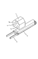
第二のステレオカメラ7も第一のステレオカメラ6と同様に3つのカメラ7a,7b,7cによって構成されるが、産業用ロボット5上でハンド4の近傍に取り付けてハンド4と一体的に移動させる関係上、カメラ7a,7b,7c間の視差は相対的に小さく、図2に示されるようにコンパクトに纏められている。
【0015】
コンピュータシステム8は、産業用ロボット5に付属するロボット制御装置10と汎用の数値制御装置9とによって構成され、このうち、ロボット制御装置10は専ら産業用ロボット5の駆動制御に、また、数値制御装置9は、画像処理等を始めとする付加機能の実現のために使用され、両者間はデータ転送可能に接続されている。
【0016】
この実施形態では市販のロボット制御装置10に改造を加えずに利用することを前提とし、画像処理等の付加機能を実現するための数値制御装置9をロボット制御装置10に追加してコンピュータシステム8としているが、画像処理等の付加機能を実装することを含めてロボット制御装置10を始めから設計し直すような場合には、単体のロボット制御装置10それ自体をコンピュータシステム8とすることも可能である。また、これとは逆に数値制御装置9に産業用ロボット5の駆動制御機能を実装し、単体の数値制御装置9をコンピュータシステム8としてもよい。
【0017】
このように、コンピュータシステム8に構成上の格別の制限はないが、ここでは、一例としてロボット制御装置10と数値制御装置9でコンピュータシステム8を構成した場合の構造について簡単に説明する。
【0018】
コンピュータシステム8の一部を構成するロボット制御装置10は、図3に示されるように、基本的な制御プログラムを格納したROM11と、ユーザが作成した動作プログラム等を記憶するための不揮発性メモリ12、および、不揮発性メモリ12に記憶された動作プログラムとROM12に格納されている制御プログラムとに基いて各種の演算処理を実行するCPU13と、演算過程のデータの一時記憶等に用いられるRAM14、ならびに、CPU13からの指令に応じて産業用ロボット5の各軸のサーボモータ(図示せず)を駆動制御する軸制御回路15とを備える。
【0019】
軸制御回路15はCPU13から与えられる移動指令に基いて各軸のサーボモータを駆動し、産業用ロボット5のハンド4の位置および姿勢と移動速度ならびに駆動トルクを制御する。
【0020】
表示装置付手動データ入力装置16は動作プログラムの編集作業等に使用され、また、入出力インターフェイス17はロボット制御装置10と数値制御装置9との間のデータ転送に使用される。
【0021】
数値制御装置9は、図4に示されるように、システムプログラムを格納したROM18と、画像の解析に用いられるアプリケーションプログラム等を記憶した不揮発性メモリ19、および、演算処理用のCPU20と、演算過程のデータの一時記憶等に用いられるRAM21、ならびに、表示装置付手動データ入力装置22と、入出力インターフェイス23、更に、画像取り込み用のフレームメモリ24によって構成される。フレームメモリ24はRAM21の一部によって構成してもよい。
【0022】
入出力インターフェイス23は数値制御装置9とロボット制御装置10とを接続してデータ転送を行うためのもので、第一のステレオカメラ6が有する3つのカメラ6a,6b,6cで撮影された画像データと第二のステレオカメラ7が有する3つのカメラ7a,7b,7cで撮影された画像データも、入出力インターフェイス23を介してフレームメモリ24に送られるようになっている。
【0023】
フレームメモリ24内のデータ配列の一例を図10に示す。この実施形態では、640ドット×480ドットの3組の画素データを256階調の濃度で記憶するようにしているが、解像度や階調等の画素の記憶条件については、必要とされる分解能等に応じて適宜に決めるものとする。
【0024】
また、図1に示されるように、コンベア3の近傍には、このコンベア3で搬送されるワーク2が所定の撮影位置に到達したことを検出するための定位置検出センサ25が設けられており、この定位置検出センサ25からの信号も入出力インターフェイス23を介して数値制御装置9のCPU20に入力されるようになっている。
【0025】
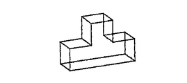
不揮発性メモリ19には、取り扱いの対象となる可能性のある様々な形状のワーク2に対応した3次元形状データが予め幾つか登録されている。不揮発性メモリ19に記憶されている3次元形状データの一例を図11に示す。
【0026】
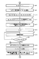
図5〜図7は数値制御装置9側のCPU20が実行するピッキング制御の概略を示したフローチャート、また、図8〜図9は数値制御装置9からの指令を受けたロボット制御装置10のCPU13が実行するパルス分配処理の概略を示したフローチャートである。
【0027】
次に、図5〜図9を参照して位置姿勢演算手段,ズレ量演算手段,位置姿勢補正手段としてのCPU20の処理動作、および、追跡動作制御手段としてのCPU20およびCPU13の処理動作、ならびに、ピッキング動作制御手段としてのCPU13の処理動作について説明する。
【0028】
ピッキング制御を開始したCPU20は、まず、定位置検出センサ25からの定位置検出信号が入力されているか否か、つまり、コンベア3で搬送されるワーク2が所定の撮影位置に到達したか否かを判定し(ステップa1)、定位置検出信号が検出されていなければ、そのまま定位置検出信号の入力を待つ待機状態を保持する。
【0029】
そして、ワーク2が所定の撮影位置に到達して定位置検出センサ25からの定位置検出信号が確認されると、CPU20は経過時間計測タイマtをリスタートさせてワーク2が所定の撮影位置に到達してからの経過時間の計測を開始すると共に(ステップa2)、第一のステレオカメラ6を作動させ、所定の撮影位置にあるワーク2を撮影してカメラ6a,6b,6cから画像を取り込み(ステップa3)、これらの画像データをフレームメモリ24に記憶する(ステップa4)。図12に取り込まれた画像の一例を示す。
【0030】
次いで、位置姿勢演算手段として機能するCPU20が、画像の解析に用いられるアプリケーションプログラムを起動し、フレームメモリ24に記憶されているワーク2の画像データを解析して3次元情報を求め(ステップa5)、この3次元情報と不揮発性メモリ19に登録されている複数の3次元形状データとを照合して現時点で作業対象となっているワーク2の形状を特定した後(ステップa6)、撮影時点つまりステップa3の実行時点におけるワーク2の位置X,Y,Zとワーク2の姿勢α,β,γを求める(ステップa7)。フレームメモリ24に記憶されているワーク2の画像データを解析して得られる3次元情報の一例を図13に、また、ワーク2の3次元情報と不揮発性メモリ19に登録されている3次元形状データとの照合例を図14に示す。
【0031】
但し、ワーク2の位置X,Y,Zは固定式の第一のステレオカメラ6を基準とした座標系であり、各座標系の向きは図1に示される通りである。また、ワーク2の姿勢α,β,γは、αがX軸回りの姿勢の傾き、βがY軸周りの姿勢の傾き、また、γがZ軸回りの姿勢の傾きである。
【0032】
前述した通り、第一のステレオカメラ6は産業用ロボット5とは独立してコンベア3の側方に固定的に設置されているので、ステレオカメラ6を構成するカメラ6a,6b,6c間の視差を大きく取ることができ、第一のステレオカメラ6を用いた検出操作におけるワーク2の位置および姿勢の認識精度を大幅に向上させることができる。
【0033】
次いで、追跡動作制御手段の一部として機能するCPU20は、コンベア3の搬送速度V(設定値)と、経過時間計測タイマtの現在値、ならびに、撮影時点つまりステップa3の実行時点におけるワーク2のX軸座標上の位置Xとに基いて、現時点におけるワーク2のX軸座標上の位置Xを更新して求める(ステップa8)。
【0034】
そして、CPU20は、入出力インターフェイス23を介してロボット制御装置10にアクセスし、軸制御回路15に設けられた各軸の現在位置記憶レジスタからハンド4の現在位置xn,yn,znの値を読み込み(ステップa9)、ワーク2の現在位置X,Y,Zの各軸の要素からハンド4の現在位置xn,yn,znの値を減じ、更に、Z軸成分に関してはオフセット量z0を加算して、ハンド4をハンド4の現在位置xn,yn,znからワーク2の現在位置X,Y,Zよりもz0だけ上方に移動させるために必要とされる移動量Dx,Dy,Dzを求める(ステップa10)。そして、Dx,Dy,Dzをインクリメンタル移動指令としてロボット制御装置10に送信する(ステップa11)。
【0035】
また、CPU20は、コンベア3の搬送速度Vに相当する速度でハンド4にX軸方向の送りを掛ける際に必要とされる単位時間当たりの分配パルス量D0xの値を求め、この値をロボット制御装置10に送信する(ステップa12)。
【0036】
次いで、CPU20は、撮影回数積算カウンタCの値を零に初期化し(ステップa13)、入出力インターフェイス23を介してロボット制御装置10にアクセスして、軸制御回路15に設けられた分配処理用の各軸の位置偏差記憶レジスタの値を読み込み(ステップa14)、その値がインポジション幅の範囲に収まっているか否かを判定する(ステップa15)。
【0037】
ステップa11の処理でロボット制御装置10にインクリメンタル移動指令を送信した直後の現段階では各軸の位置偏差は増大しており、その値がインポジション幅の範囲に収まることはないので、CPU20は、ステップa14〜ステップa15の処理を繰り返し実行して、各軸の位置偏差記憶レジスタの値がインポジション幅の範囲に収まるのを待機することになる。
【0038】
一方、ステップa11の処理でロボット制御装置10に送信されたインクリメンタル移動指令Dx,Dy,Dzは、ロボット制御装置10側のCPU13によりステップb1の処理で検出され、これを検出したCPU13は、各インクリメンタル移動指令Dx,Dy,Dzを各軸の位置偏差記憶レジスタErx,Ery,Erzにセットする(ステップb2)。そして、更に、数値制御装置9から送信された分配パルス量D0xの値を読み込み(ステップb3)、この値を記憶した後(ステップb4)、軸制御回路15のトルクリミット回路にトルクリミットを設定して(ステップb5)、公知のパルス分配処理を開始する(ステップb6)。
【0039】
ステップb6のパルス分配処理では、各軸の位置偏差記憶レジスタErx,Ery,Erzに記憶されたインクリメンタル移動指令Dx,Dy,DzをDx:Dy:Dzの比率で単位時間当たりの微小な移動指令ΔDx,ΔDy,ΔDzとして各軸のサーボモータにパルス分配周期毎の移動指令として送出する処理が繰り返され、その都度、各軸の位置偏差記憶レジスタErx,Ery,Erzから分配済みのパルス量ΔDx,ΔDy,ΔDz(パルスコーダからのフィードバックパルス)が減算される。
【0040】
そして、1周期分のパルス分配処理がステップb6で完了する度、追跡動作制御手段の一部として機能するCPU13が、X軸に関する位置偏差記憶レジスタErxに分配パルスD0xの値を加算する(ステップb7)。
【0041】
次いで、CPU13は、数値制御装置9からの補正指令dx,dy,dz,Dα,Dβ,Dγが入力されているか否か(ステップb8)、および、数値制御装置9からのピッキング指令やプレイス指令が入力されているか否か(ステップb10)を判定することになるが、この段階では何れの指令も入力されないので、追跡動作制御手段の一部として機能するCPU13は、ステップステップb6〜ステップb8とステップb10の処理のみを繰り返し実行することになる。
【0042】
まず、ステップb6およびステップb7の繰り返し処理が開始された直後の段階では、各軸の位置偏差記憶レジスタErx,Ery,Erzの値は実質的にDx,Dy,Dzであって位置偏差が十分に大きいため、ハンド4はトルクリミットを越えない範囲の強い力つまり速い速度で駆動制御され、コンベア3と共に移動するワーク2を追って其の上方z0の位置まで直線補間によって移動されることになる。このとき、ワーク2はコンベア3の搬送によってX軸方向に移動するが、ステップb7の処理によりX軸の位置偏差記憶レジスタErxの値が分配周期毎にD0xずつ加算されるので、Dx,Dy,Dzの位置偏差が解消された場合であっても位置偏差記憶レジスタErxにはD0xの位置偏差が定常的に滞留することになり、この位置偏差D0xを解消しようとする軸制御回路15の働きにより、ハンド4がコンベア3上のワーク2と同様にしてX軸方向に移動速度Vで送られることになる。
【0043】
このようにして、位置偏差記憶レジスタErx,Ery,Erzの位置偏差が概ね解消され、ハンド4がワーク2の上方z0の目標位置に追い付き、位置偏差記憶レジスタErxに滞留する位置偏差D0xのみによってハンド4がワーク2と一定の位置関係を保ってX軸方向に移動するようになると、各軸の位置偏差記憶レジスタの値がインポジション幅の範囲に収まるようになり、数値制御装置9側のCPU20がステップa15の処理でこれを検出する。
【0044】
そこで、ズレ量演算手段として機能するCPU20は、ワーク2と一定の位置関係を保って移動する第二のステレオカメラ7を作動させ、ワーク2を撮影してカメラ7a,7b,7cから画像を取り込み(ステップa16)、これらの画像データをフレームメモリ24に記憶する(ステップa17)。
【0045】
次いで、ズレ量演算手段として機能するCPU20が、画像の解析に用いられるアプリケーションプログラムを起動し、例えば、フレームメモリ24に記憶されている画像の中央部近傍を最初の探索領域としてワーク2の画像を探索し、ワーク2の各軸方向の位置のズレ量(Δx,Δy,Δz)と、ステップa7の処理で求められたワーク2の姿勢(α,β,γ)を基準とする各軸の回りのワーク2の姿勢のズレ量(Δα,Δβ,Δγ)を求める(ステップa18)。
【0046】
この実施形態では、図8に示したパルス分配処理により、ステップa7の処理で求められたワーク2の位置(X,Y,Z)を基準として、その上方z0の位置にハンド4を移動させるように駆動制御しているので、ハンド4に対する第二のステレオカメラ7のオフセット量を差し引くことを前提として、基本的には、第二のステレオカメラ7の座標原点(0,0,0)がステップa7の処理で求められたワーク2の位置(X,Y,Z)と一致することになる。但し、ここでのXの値は搬送過程における変動的な値であり、実質的には、X=X(ステップa7の初期値)+V・tである。つまり、第二のステレオカメラ7の座標系はハンド4およびコンベア3と共にX軸方向に併進する座標系であり、ハンド4に対するステレオカメラ7のオフセット量を差し引くことを前提とした場合、途中で荷崩れ等が生じてコンベア3に対してワーク2が相対移動しない限り、ワーク2は常に第二のステレオカメラ7の画像の中央部に捕捉されることになる。従って、第一のステレオカメラ6による撮影完了後、コンベア3に対するワーク2の位置に変動がない限り、(Δx,Δy,Δz)の値も(Δα,Δβ,Δγ)の値も基本的に零である。
【0047】
一方、途中で荷崩れ等が生じてコンベア3に対してワーク2が相対移動したり姿勢が崩れたりした場合には、そのズレ量がステップa18の処理によって(Δx,Δy,Δz)や(Δα,Δβ,Δγ)として求められる。この場合、CPU20は、(Δx,Δy,Δz)および(Δα,Δβ,Δγ)の値をワーク2の次の探索領域として記憶した後(ステップa19)、撮影回数積算カウンタCの値を1インクリメントし(ステップa20)、撮影の繰り返し回数Cが設定回数Nに達しているか否かを判定する(ステップa21)。
【0048】
そして、撮影回数積算カウンタCの値が設定回数Nに達していなければ、ズレ量演算手段として機能するCPU20は、前記と同様にしてステップa16〜ステップa21の処理を繰り返し実行し、その都度、ワーク2に関する各軸方向の位置のズレ量(Δx,Δy,Δz)と各軸の回りの姿勢のズレ量(Δα,Δβ,Δγ)を求めると共に、これらの値をワーク2の新たな探索領域として更新して記憶していく。
【0049】
この間、荷崩れ等が生じてコンベア3に対してワーク2が相対移動したり姿勢が崩れたりする場合もあるが、一撮影周期間の位置および姿勢のズレ量は大きくはなく、しかも、直前の処理周期で記憶されたワーク2の位置や姿勢のズレ量(ステップa19参照)に基いて、次の処理周期で、其の近傍でワーク2の画像が探索されるので(ステップa18参照)、ワーク2の位置および姿勢の不連続的な変化に伴うデータ探索の負荷の増大によってエラーが発生することなく、ワーク2の実位置および実姿勢のズレ量を的確に追跡することができる。
【0050】
また、第一のステレオカメラ6によるワーク2の位置および姿勢の認識精度が高いため、第二のステレオカメラ7による第1回目の撮影時点でワーク2を的確に視野に納めることができ、しかも、画像データの探索領域を絞り込むことも可能となるため、全体としての処理速度の短縮に有益である。
【0051】
第二のステレオカメラ7の視差は第一のステレオカメラ6の視差と比べて相対的に小さいが、ワーク2に対して十分に接近して撮影を行うことができるので、十分な精度でワーク2の位置および姿勢のズレを検出することができる。
【0052】
そして、撮影回数積算カウンタCの値が設定回数Nに達したことがステップa21の判定処理によって検出されると、位置姿勢補正手段として機能するCPU20は、最後に求められた位置のズレ量、つまり、ハンド4およびコンベア3と共にX軸方向に併進する座標系内におけるワーク2の最終的な位置のズレ量Δx,Δy,Δzを位置ズレ補正のためのインクリメンタル移動指令dx,dy,dzとして記憶し、Z軸方向の補正量に関しては上方へのオフセットz0を解消するための補正値−z0を更に加算すると共に、最後に求められた姿勢のズレ量Δα,Δβ,Δγをステップa7の処理で求められたα,β,γに加算してワーク2の絶対的な姿勢α,β,γを求める(ステップa22)。
【0053】
次いで、位置姿勢補正手段として機能するCPU20は、入出力インターフェイス23を介してロボット制御装置10にアクセスし、軸制御回路15に設けられた各軸の現在姿勢記憶レジスタからハンド4の現在姿勢αn,βn,γnを読み込み(ステップa23)、ワーク2を把持するためにハンド4に必要とされる姿勢α,β,γの各軸の要素からハンド4の現在姿勢αn,βn,γnの各軸の要素の値を減じ、ハンド4を現在の姿勢αn,βn,γnからワーク2の把持に適した姿勢α,β,γに変化させるために必要とされる姿勢変化量Dα,Dβ,Dγを求め(ステップa24)、位置ズレ補正のためのインクリメンタル移動指令dx,dy,dzとハンド4の姿勢制御のためのインクリメンタル姿勢変更指令Dα,Dβ,Dγをロボット制御装置10に送信する(ステップa25)。
【0054】
次いで、CPU20は、入出力インターフェイス23を介してロボット制御装置10にアクセスして、軸制御回路15に設けられた分配処理用の各軸の位置偏差記憶レジスタおよび姿勢偏差記憶レジスタの値を読み込み(ステップa26)、その値がインポジション幅の範囲に収まっているか否かを判定する(ステップa27)。ステップa25の処理でロボット制御装置10にインクリメンタル移動指令とインクリメンタル姿勢変更指令を送信した直後の現段階では各軸の位置偏差および姿勢偏差は増大しており、その値がインポジション幅の範囲に収まることはないので、CPU20は、ステップa26〜ステップa27の処理を繰り返し実行して、各軸の位置偏差記憶レジスタおよび姿勢偏差記憶レジスタの値がインポジション幅の範囲に収まるのを待機することになる。
【0055】
一方、ステップa25の処理でロボット制御装置10に送信されたインクリメンタル移動指令dx,dy,dzとインクリメンタル姿勢変更指令Dα,Dβ,Dγは、ロボット制御装置10側のCPU13によりステップb8の処理で検出され、これを検出したCPU13は、各インクリメンタル移動指令dx,dy,dzを各軸の位置偏差記憶レジスタErx,Ery,Erzに加算すると共に、各軸の姿勢偏差記憶レジスタErα,Erβ,Erγにインクリメンタル姿勢変更指令Dα,Dβ,Dγをセットする(ステップb9)。
【0056】
そして、このようにして更新された各軸の位置偏差記憶レジスタErx,Ery,Erzと各軸の姿勢偏差記憶レジスタErα,Erβ,Erγの値に基いて、ピッキング動作制御手段として機能するCPU13が前記と同様にしてステップb6〜ステップb8とステップb10の処理のみを繰り返し実行する。
【0057】
この結果、ステップb6のパルス分配処理では、ハンド4に対してX軸の方向に速度Vの送りを掛ける処理と重畳して、X,Y,Zの各軸方向に対してdx,dy,dzの位置ズレ補正の送りを掛ける処理と、ハンド4の姿勢をX,Y,Zの各軸の回りにDα,Dβ,Dγだけ姿勢変化(回転)させる処理とが並行して行われることになる。
【0058】
そして、位置偏差記憶レジスタErx,Ery,Erzの位置偏差が概ね解消され、ハンド4がワーク2を把持できる位置に達し、また、姿勢偏差記憶レジスタErα,Erβ,Erγの姿勢偏差が解消されてハンド4がワーク2の表裏を法線方向から把持できる姿勢に達すると、ハンド4は、前述した位置偏差D0xの働きにより、この状態を保持したまま速度Vでワーク2と共にX軸方向にのみ移動する。
【0059】
一方、数値制御装置9側のCPU20は、ステップa27の判定処理によって位置偏差記憶レジスタErx,Ery,Erzおよび姿勢偏差記憶レジスタErα,Erβ,Erγの偏差がインポジション幅に入ったことを検出し、ロボット制御装置10に対してピッキング指令とプレイス指令を送信する(ステップa28)。
【0060】
そして、ステップb10の処理でこれらの指令を検出したCPU13が、ハンド4を閉鎖させてワーク2を把持させ(ステップb11)、各軸のエラーレジスタをクリアした後(ステップb12)、予め設定されているワーク受け渡し位置にハンド4を移動させてワーク2を置き(ステップb13)、数値制御装置9に完了信号を送信して(ステップb14)、数値制御装置9からの原位置復帰指令を待つ待機状態に入る(ステップb15)。
【0061】
そして、ステップa29の処理で完了信号を検出したCPU20は、ロボット制御装置10に現位置復帰指令を出力した後(ステップa30)、定位置検出センサ25からの定位置検出信号を待つ初期の待機状態に復帰し(ステップa1)、また、原位置復帰指令を検出したCPU13は、ハンド4を初期設定位置のアプローチポイントに戻した後(ステップb16)、数値制御装置9からのインクリメンタル移動指令Dx,Dy,Dzの入力を待つ初期の待機状態に復帰する(ステップb1)。
【0062】
以上、一実施形態として、コンベア3によって搬送されるワーク2に対してハンド4を同期移動させながらワーク2を把持する場合について説明したが、定位置検出センサ25がワーク2を検出した時点でコンベア3を停止させてワーク2を把持するような構成、つまり、ワーク2の載置位置が略一定となるようなピッキング装置に対しても、各種の設定値を変更することにより、図5〜図7に示した数値制御装置9側のCPU20の処理や図8〜図9に示したロボット制御装置10側のCPU13の処理をそのまま適用することが可能である。
【0063】
具体的には、ステップa8における変数Vとステップa12における変数D0xの値を共に零として設定し、ステップa21で判定基準となるNの値を1に設定すればよい。
【0064】
この場合、ズレ量演算手段は、第一のステレオカメラ6で撮影されたワーク位置の近傍までハンド4を移動させて一度だけ第二のステレオカメラ7を作動させてワーク2の初期位置および初期姿勢に対するワーク2の実位置および実姿勢のズレ量を求めるように機能し(N=1)、追跡動作制御手段は、事実上、非作動の状態となる(V=D0x=0)。
【0065】
また、最初に述べた実施形態においてワーク2に対してハンド4を同期移動させる際に、第二のステレオカメラ7を様々な方向に移動させて撮影条件を変えることで全体としての位置や姿勢のズレの検出精度を向上させることも可能である。第二のステレオカメラ7の位置や姿勢を変化させる方法としては、ハンド4の送り動作を調整する方法と、ハンド4と第二のステレオカメラ7との間に第二のステレオカメラ7の位置や姿勢を変えるためのアクチュエータを実装する方法とが考えられる。
【0066】
前者に関しては、基本的に、図8のステップb6〜ステップ10に示されるようなパルス分配処理において追跡動作の途中で強制的にハンド4を移動させる適当な移動指令(オフセット指令)を入力することにより達成可能である。当然、ハンド4の位置の変化によって第二のステレオカメラ7によるワーク2の見え方つまり位置や姿勢に変化が生じるが、この場合、この位置や姿勢のズレ自体がハンド4の位置や姿勢の補正量と同等にして機能することになるので駆動制御上の問題は発生しない。例えば、ハンド4を通常の位置からオフセット指令で5センチだけ+Yの方向に移動させて第二のステレオカメラ7による撮影を行ったとすると、結果として、ワーク2が最初の位置から−Yの方向に5センチ位置ズレしたものと判定されることになるので、Δyの値は−5センチとなり、結果的に、ハンド4は通常の位置からオフセット指令で強制的に5センチだけ+Yの方向に移動された位置から−Yの方向に5センチだけ位置を補正され、最終的に、ピッキングに最適の位置に戻されることになる。
【0067】
また、アクチュエータを使用してハンド4に対する第二のステレオカメラ7の位置や姿勢を変える場合には、ステップa7の処理で求められたワーク2の位置(X,Y,Z)にハンド4を移動させてハンド4に対する第二のステレオカメラ7のオフセット量を差し引くことで第二のステレオカメラ7の座標原点を実質的に第一のステレオカメラ6の座標位置(X,Y,Z)に一致させる場合と同様、アクチュエータの作動状況に応じてハンド4に対する第二のステレオカメラ7のオフセット量を差し引くことで対処することが可能である。
【0068】
【発明の効果】
本発明のピッキング装置は、最初にワークの位置および姿勢を検出するために使用される第一のステレオカメラを産業用ロボットとは独立して固定的に設置することで第一のステレオカメラを構成するカメラ間の視差を大きく取るようにしたので、第一のステレオカメラを用いた初期段階の検出操作におけるワークの位置および姿勢の認識精度が向上し、第二のステレオカメラは撮影対象となる領域を狭く絞り込んで撮影するだけで確実にワークを撮影することが可能となり、解析の対象となる画像データの容量が軽減されるので、ワークの実位置および実姿勢のズレ量の演算に必要とされる所要時間が短縮されて高速の演算処理が実現される。
第二のステレオカメラは産業用ロボット上でハンドの近傍に取り付ける必要上、カメラ間の視差を短くしたコンパクトな構成とされるが、ワークに接近した状態でワークを撮影することができるので、十分な精度でワークの位置および姿勢のズレを検出することができる。
【0069】
また、ワークの移動位置に追従させてハンドを移動させながら第二のステレオカメラを繰り返し作動させてワークの位置および姿勢のズレ量を求めるようにしたので、荷崩れ等によってコンベア上のワークの位置や姿勢に変化が生じた場合であっても、位置や姿勢のズレ量に応じてピッキング動作の目標位置やハンドの姿勢を適切に補正して確実なピッキング動作を行うことができる。
【図面の簡単な説明】
【図1】本発明を適用した一実施形態のピッキング装置の構成を簡略化して示した模式図である。
【図2】第二のステレオカメラの外観を簡略化して示した斜視図である。
【図3】コンピュータシステムの一部を構成するロボット制御装置の要部を示した機能ブロック図である。
【図4】コンピュータシステムの一部を構成する数値制御装置の要部を示した機能ブロック図である。
【図5】数値制御装置側のCPUが実行するピッキング制御の概略を示したフローチャートである。
【図6】ピッキング制御の概略を示したフローチャートの続きである。
【図7】ピッキング制御の概略を示したフローチャートの続きである。
【図8】ロボット制御装置のCPUが実行するパルス分配処理の概略を示したフローチャートである。
【図9】パルス分配処理の概略を示したフローチャートの続きである。
【図10】フレームメモリ内のデータ配列の一例を示した概念図である。
【図11】不揮発性メモリに記憶されている3次元形状データの一例を示した概念図である。
【図12】第一のステレオカメラで撮影された画像の一例を示した概念図である。
【図13】ワークの画像データを解析して得られる3次元情報の一例を示した概念図である。
【図14】ワークの3次元情報と不揮発性メモリに登録されている3次元形状データとの照合例を示した概念図である。
【符号の説明】
1 ピッキング装置
2 ワーク
3 コンベア
4 ハンド
5 産業用ロボット
6 第一のステレオカメラ
6a,6b,6c カメラ
7 第二のステレオカメラ
7a,7b,7c カメラ
8 コンピュータシステム
9 数値制御装置(コンピュータシステムの一部)
10 ロボット制御装置(コンピュータシステムの一部)
11 ROM
12 不揮発性メモリ
13 CPU(追跡動作制御手段の一部,ピッキング動作制御手段)
14 RAM
15 軸制御回路
16 表示装置付手動データ入力装置
17 入出力インターフェイス
18 ROM
19 不揮発性メモリ
20 CPU(位置姿勢演算手段,ズレ量演算手段,位置姿勢補正手段,追跡動作制御手段の一部)
21 RAM
22 表示装置付手動データ入力装置
23 入出力インターフェイス
24 フレームメモリ
25 定位置検出センサ[0001]
TECHNICAL FIELD OF THE INVENTION
The present invention relates to an improvement in a picking device that grasps a workpiece by grasping the position and orientation of the workpiece, and particularly relates to an improvement for improving accuracy and processing speed related to detection of the position and orientation.
[0002]
[Prior art]
As a technique for improving the accuracy of grasping the position and orientation of a workpiece by using two camera systems, for example, a robot device disclosed in Japanese Patent Application Laid-Open No. 2000-288974 has already been proposed.
[0003]
The robot device disclosed in JP-A-2000-288974 is provided with a first visual sensor composed of a two-dimensional visual sensor and a second visual sensor composed of a two-dimensional visual sensor or a three-dimensional visual sensor at the tip of the wrist of the robot. The rough position and posture of the work are detected by one visual sensor, the wrist of the robot is moved to a position near the work position obtained by the first visual sensor, and the second visual sensor is operated to operate the robot. The position and the posture are strictly measured, and the picking operation by the industrial robot is performed.
[0004]
[Problems to be solved by the invention]
However, in the robot apparatus of Japanese Patent Application Laid-Open No. 2000-288974, since the first visual sensor is constituted by a two-dimensional visual sensor, it is necessary to perform highly accurate recognition by an initial-stage detection operation using the first visual sensor. As a result, it is difficult to effectively narrow down an area to be photographed in a precise measurement operation performed using the second visual sensor, and the time required for capturing images and performing arithmetic processing is difficult. The adverse effect such as an increase in the size of the image occurs.
[0005]
In addition, as a result of an increase in the time required for capturing images and performing arithmetic processing, it is practically impossible to detect the position and orientation of a moving workpiece and perform a picking operation.
[0006]
[Object of the invention]
Accordingly, an object of the present invention is to solve the above-mentioned drawbacks of the prior art, reduce the time required for image capture and arithmetic processing, and recognize the position and orientation of a work with high speed and high accuracy. It is another object of the present invention to provide a picking device that can handle picking of a moving workpiece.
[0007]
[Means for Solving the Problems]
The present invention relates to an articulated industrial robot having a hand for gripping a work, a camera for grasping the position and orientation of the work, and a picking device including a computer system for driving and controlling the industrial robot and the camera. In order to achieve the above object, in particular,
While the first stereo camera having a large parallax is fixedly installed near the mounting position of the work, the second stereo camera having a relatively small parallax is arranged near the hand in the industrial robot,
In the computer system, position and orientation calculating means for determining the position and orientation of the work based on the image captured by the first stereo camera,
The hand is moved to the vicinity of the work position calculated by the position and orientation calculating means, the second stereo camera is operated to capture an image, and the actual position of the work relative to the position and orientation of the work determined by the position and attitude calculating means is calculated. A shift amount calculating means for obtaining a shift amount between the position and the actual posture;
Position and orientation for obtaining the final work position and orientation based on the position and orientation of the work determined by the position and orientation calculation means and the actual position and actual position shift of the work determined by the shift amount calculation means Correction means;
A picking operation control means for controlling the target position of the picking operation and the posture of the hand based on the position and posture of the work obtained by the position and posture correcting means is provided.
[0008]
In the above configuration, first, the first stereo camera installed near the work placement position captures an image around the work, and the position and orientation calculation means analyzes the image to determine the position and orientation of the work. . Since the first stereo camera is fixedly installed independently of the industrial robot, it is possible to take a large parallax between the cameras constituting the stereo camera, and the initial stereo camera using the first stereo camera is used. The accuracy of recognition of the position and orientation of the work in the step detection operation is improved.
Next, the shift amount calculating means moves the hand to the vicinity of the work position calculated by the position and attitude calculating means, activates the second stereo camera to capture an image, and is obtained by the position and attitude calculating means. The amount of deviation between the actual position and the actual posture of the work with respect to the position and the posture of the work is obtained. Since the recognition accuracy of the position and orientation of the work by the first stereo camera is high, the second stereo camera can reliably capture the work only by narrowing down the area to be photographed and photographing. In other words, by reducing the capacity of the image data to be analyzed, the time required for calculating the amount of deviation between the actual position and the actual posture of the work is reduced, and high-speed arithmetic processing is realized. become.
Since the second stereo camera is mounted near the hand on the industrial robot, the parallax between the cameras that make up the stereo camera cannot be as large as the first stereo camera, but when the camera is close to the work Since the work can be photographed, the deviation of the position and the posture of the work can be detected with sufficient accuracy.
Then, based on the position and orientation of the work determined by the position and orientation calculating means and the actual position and actual position of the work determined by the shift amount calculating means, the position and orientation correcting means determines the final position and orientation of the workpiece. The posture is obtained, and the picking operation control means controls the target position of the picking operation and the posture of the hand based on the position and posture of the work obtained by the position and posture correction means.
[0009]
Also, a multi-joint type industrial robot having a conveyor for transporting a workpiece, a hand for gripping the workpiece, a camera for grasping the position and orientation of the workpiece, and a computer system for driving and controlling the industrial robot and the camera. In the case of a picking device with
While fixedly installing a first stereo camera having a large parallax for photographing a work conveyed on a conveyor at a predetermined position, a second stereo camera having a relatively small parallax near a hand in an industrial robot is provided. Deploy,
The computer system, a position and orientation calculating means for determining the position and orientation of the work at the predetermined position based on an image captured by a first stereo camera,
Tracking operation control means for determining the current position of the work based on the work position and the conveyor speed and elapsed time determined by the position and orientation calculation means, and moving the hand following the current position of the work;
During the operation of the tracking operation control means, the second stereo camera is repeatedly operated to take an image in a coordinate system which is translated together with the hand and the conveyor, and the position of the work with respect to the position and posture of the work determined by the position and posture calculation means is taken. Deviation amount calculating means for calculating the deviation amount between the actual position and the actual posture;
Based on the position and orientation of the work determined by the position and orientation calculation means and the actual position and actual position shift of the work determined by the shift amount calculation means, the final position in the coordinate system that translates with the hand and the conveyor. Position and orientation correction means for determining the position and orientation of a typical work,
A picking operation control means for controlling the target position of the picking operation and the posture of the hand based on the position and posture of the work obtained by the position and posture correcting means is provided.
[0010]
When such a configuration is applied, the tracking operation control means obtains the current position of the work based on the work position obtained by the position and orientation calculation means, the conveyor speed and the elapsed time, and causes the current position of the work to follow. Since the hand is moved, even if the work moves, the relative positional relationship between the work and the hand is always kept constant unless the position and posture of the work on the conveyor change. .
Therefore, there is no change in the positional relationship between the hand and the work due to the time lag from the start of shooting by the first stereo camera to the drive control of the hand by the picking operation control means. As in the case where the camera calculates the deviation between the actual position and the actual posture of the workpiece and controls the target position of the picking operation and the posture of the hand, a reliable picking operation can be performed.
Also, if a change occurs in the relative positional relationship between the work and the second stereo camera, this means that the position or posture of the work on the conveyor has changed due to collapse of the load, etc. The position / posture correction unit corrects the target position of the picking operation and the posture of the hand according to the amount of deviation of the posture, so that the picking operation can be reliably performed even if the work conveyed by the conveyor collapses. It becomes possible.
In addition, the shift amount calculating means repeatedly operates the second stereo camera while the tracking operation control means is operating, captures an image in a coordinate system which is translated along with the hand and the conveyor, and obtains the actual position and actual posture of the work. Even if the position or posture of the work on the conveyor changes due to collapse of load, etc., the position and posture of the work detected in the immediately preceding process are initialized. It is possible to execute the calculation processing of the shift amount as the position, and it is possible to greatly reduce the time required for calculating the shift amount of the actual position and the actual posture of the work. Also, even if a large change occurs as a result in the position and orientation of the workpiece on the conveyor, the amount of displacement of the position and orientation during one shooting cycle is not large, so that the position and orientation may change discontinuously. The deviation amount of the actual position and the actual posture of the work can be tracked without causing an error due to an increase in the load of the data search.
[0011]
BEST MODE FOR CARRYING OUT THE INVENTION
Hereinafter, embodiments of the present invention will be described in detail with reference to the drawings. FIG. 1 is a schematic diagram showing a simplified configuration of a
[0012]
The
[0013]
The
[0014]
The second stereo camera 7 is also composed of three
[0015]
The
[0016]
In this embodiment, it is assumed that a commercially
[0017]
As described above, there is no particular limitation on the configuration of the
[0018]
As shown in FIG. 3, a
[0019]
The
[0020]
The manual
[0021]
As shown in FIG. 4, the
[0022]
The input /
[0023]
FIG. 10 shows an example of a data array in the
[0024]
Further, as shown in FIG. 1, a fixed
[0025]
In the
[0026]
FIGS. 5 to 7 are flowcharts showing an outline of picking control executed by the
[0027]
Next, with reference to FIGS. 5 to 9, the processing operation of the
[0028]
The
[0029]
When the
[0030]
Next, the
[0031]
However, the positions X, Y, and Z of the
[0032]
As described above, since the
[0033]
Next, the
[0034]
Then, the
[0035]
Further, the
[0036]
Next, the
[0037]
At this stage immediately after transmitting the incremental movement command to the
[0038]
On the other hand, the incremental movement commands Dx, Dy, Dz transmitted to the
[0039]
In the pulse distribution processing of step b6, the position deviation storage register E of each axis r x, E r y, E r The incremental movement commands Dx, Dy, Dz stored in z are converted into minute movement commands ΔDx, ΔDy, ΔDz per unit time at a ratio of Dx: Dy: Dz to the servo motors of each axis as movement commands for each pulse distribution cycle. The sending process is repeated, and each time the position deviation storage register E for each axis is r x, E r y, E r The distributed pulse amounts ΔDx, ΔDy, ΔDz (feedback pulses from the pulse coder) are subtracted from z.
[0040]
Each time the pulse distribution processing for one cycle is completed in step b6, the
[0041]
Next, the
[0042]
First, at the stage immediately after the start of the repetitive processing of step b6 and step b7, the position deviation storage register E of each axis is set. r x, E r y, E r Since the value of z is substantially Dx, Dy, Dz and the positional deviation is sufficiently large, the hand 4 is driven and controlled with a strong force within a range not exceeding the torque limit, that is, at a high speed, and the
[0043]
Thus, the position deviation storage register E r x, E r y, E r The position deviation of z is almost eliminated, and the hand 4 0 And the position deviation storage register E r Position deviation D staying at x 0 When the hand 4 moves in the X-axis direction while maintaining a fixed positional relationship with the
[0044]
Then, the
[0045]
Next, the
[0046]
In this embodiment, by the pulse distribution process shown in FIG. 8, the position z (X, Y, Z) of the
[0047]
On the other hand, when the
[0048]
If the value of the number-of-photographs accumulation counter C has not reached the set number N, the
[0049]
During this time, the
[0050]
In addition, since the position and orientation of the
[0051]
Although the parallax of the second stereo camera 7 is relatively small as compared with the parallax of the
[0052]
Then, when it is detected by the determination processing in step a21 that the value of the number-of-photographing-times integration counter C has reached the set number N, the
[0053]
Next, the
[0054]
Next, the
[0055]
On the other hand, the incremental movement commands dx, dy, dz and the incremental posture change commands Dα, Dβ, Dγ transmitted to the
[0056]
Then, the position deviation storage register E of each axis updated in this manner is used. r x, E r y, E r z and attitude deviation storage register E for each axis r α, E r β, E r Based on the value of γ, the
[0057]
As a result, in the pulse distribution process of step b6, the process of applying the speed V to the hand 4 in the X-axis direction is superimposed, and the dx, dy, dz is performed in each of the X, Y, and Z axis directions. And the process of changing (rotating) the attitude of the hand 4 by Dα, Dβ, and Dγ around the X, Y, and Z axes is performed in parallel. .
[0058]
Then, the position deviation storage register E r x, E r y, E r The position deviation of z is almost eliminated, the hand 4 reaches a position where the
[0059]
On the other hand, the
[0060]
Then, the
[0061]
After detecting the completion signal in the process of step a29, the
[0062]
As described above, as one embodiment, the case where the
[0063]
Specifically, the variable V in step a8 and the variable D in step a12 0 The value of x may be set to zero, and the value of N serving as a criterion may be set to 1 in step a21.
[0064]
In this case, the shift amount calculating means moves the hand 4 to the vicinity of the work position photographed by the
[0065]
In addition, when the hand 4 is synchronously moved with respect to the
[0066]
Regarding the former, basically, an appropriate movement command (offset command) for forcibly moving the hand 4 during the tracking operation in the pulse distribution processing as shown in step b6 to step 10 in FIG. Can be achieved. Naturally, a change in the position of the hand 4 causes a change in the appearance of the
[0067]
When the position and orientation of the second stereo camera 7 with respect to the hand 4 are changed using the actuator, the hand 4 is moved to the position (X, Y, Z) of the
[0068]
【The invention's effect】
The picking device of the present invention configures the first stereo camera by first and fixedly installing the first stereo camera used for detecting the position and orientation of the work independently of the industrial robot. The parallax between the cameras to be taken is large, so that the recognition accuracy of the position and orientation of the workpiece in the initial stage of the detection operation using the first stereo camera is improved, and the second stereo camera is an area to be photographed. It is necessary to calculate the amount of deviation between the actual position and actual posture of the work because it is possible to reliably shoot the work only by narrowing down the image and reducing the amount of image data to be analyzed. Required time is shortened, and high-speed arithmetic processing is realized.
The second stereo camera needs to be mounted near the hand on the industrial robot, and has a compact configuration that shortens the parallax between the cameras.However, since the work can be taken close to the work, it is sufficient. It is possible to detect the deviation of the position and the posture of the work with high accuracy.
[0069]
In addition, the second stereo camera is repeatedly operated while moving the hand while following the moving position of the work to obtain the deviation of the position and posture of the work, so that the position of the work on the conveyor due to collapse of the load or the like. Even if a change occurs in the position or posture, the target position of the picking operation or the posture of the hand can be appropriately corrected in accordance with the amount of deviation of the position or posture, and a reliable picking operation can be performed.
[Brief description of the drawings]
FIG. 1 is a schematic diagram showing a simplified configuration of a picking device according to an embodiment to which the present invention is applied.
FIG. 2 is a simplified perspective view showing the appearance of a second stereo camera.
FIG. 3 is a functional block diagram showing a main part of a robot control device constituting a part of the computer system.
FIG. 4 is a functional block diagram showing a main part of a numerical control device constituting a part of the computer system.
FIG. 5 is a flowchart showing an outline of picking control executed by a CPU of the numerical controller.
FIG. 6 is a continuation of the flowchart showing an outline of picking control.
FIG. 7 is a continuation of the flowchart showing an outline of picking control.
FIG. 8 is a flowchart schematically showing a pulse distribution process executed by a CPU of the robot control device.
FIG. 9 is a continuation of the flowchart showing an outline of the pulse distribution processing.
FIG. 10 is a conceptual diagram showing an example of a data array in a frame memory.
FIG. 11 is a conceptual diagram showing an example of three-dimensional shape data stored in a nonvolatile memory.
FIG. 12 is a conceptual diagram illustrating an example of an image captured by a first stereo camera.
FIG. 13 is a conceptual diagram showing an example of three-dimensional information obtained by analyzing image data of a work.
FIG. 14 is a conceptual diagram showing an example of collation between three-dimensional information of a work and three-dimensional shape data registered in a nonvolatile memory.
[Explanation of symbols]
1 Picking device
2 Work
3 conveyor
4 hands
5 Industrial robots
6 first stereo camera
6a, 6b, 6c camera
7 Second stereo camera
7a, 7b, 7c camera
8 Computer system
9 Numerical control unit (part of computer system)
10 Robot controller (part of computer system)
11 ROM
12 Non-volatile memory
13 CPU (part of tracking operation control means, picking operation control means)
14 RAM
15 axis control circuit
16 Manual data input device with display
17 Input / output interface
18 ROM
19 Non-volatile memory
20 CPU (part of position and orientation calculation means, deviation amount calculation means, position and orientation correction means, tracking operation control means)
21 RAM
22 Manual data input device with display
23 I / O interface
24 frame memory
25 Fixed position detection sensor
Claims (2)
前記ワークの載置位置の近傍に大きな視差を有する第一のステレオカメラを固定的に設置する一方、前記産業用ロボットにおける前記ハンドの近傍に相対的に視差の小さな第二のステレオカメラを配備し、
前記コンピュータシステムには、前記第一のステレオカメラによって撮影された画像に基いて前記ワークの位置および姿勢を求める位置姿勢演算手段と、
前記位置姿勢演算手段によって求められたワーク位置の近傍まで前記ハンドを移動させ前記第二のステレオカメラを作動させて画像を撮影し、前記位置姿勢演算手段によって求められたワークの位置および姿勢に対するワークの実位置および実姿勢のズレ量を求めるズレ量演算手段と、
前記位置姿勢演算手段によって求められたワークの位置および姿勢と前記ズレ量演算手段によって求められたワークの実位置および実姿勢のズレ量とに基いて最終的なワークの位置および姿勢を求める位置姿勢補正手段と、
前記位置姿勢補正手段によって求められたワークの位置および姿勢に基いてピッキング動作の目標位置とハンドの姿勢を制御するピッキング動作制御手段とを設けたことを特徴とするピッキング装置。An articulated industrial robot having a hand for gripping a work, a camera for grasping the position and orientation of the work, and a picking device including a computer system for driving and controlling the industrial robot and camera,
While a first stereo camera having a large parallax is fixedly installed near the mounting position of the work, a second stereo camera having a relatively small parallax is arranged near the hand in the industrial robot. ,
In the computer system, position and orientation calculating means for determining the position and orientation of the work based on an image captured by the first stereo camera,
The hand is moved to the vicinity of the work position obtained by the position / posture calculation means, the second stereo camera is operated to capture an image, and the work corresponding to the position and posture of the work obtained by the position / posture calculation means is obtained. Deviation amount calculating means for calculating the deviation amount of the actual position and the actual posture of
Position and orientation for obtaining the final work position and orientation based on the position and orientation of the work determined by the position and orientation calculation means and the actual position and actual position shift of the work determined by the shift amount calculation means Correction means;
A picking operation control means for controlling a target position of the picking operation and a posture of the hand based on the position and posture of the work obtained by the position and posture correction means.
前記コンベア上を搬送されるワークを所定位置で撮影する大きな視差を有する第一のステレオカメラを固定的に設置する一方、前記産業用ロボットにおける前記ハンドの近傍に相対的に視差の小さな第二のステレオカメラを配備し、
前記コンピュータシステムには、前記第一のステレオカメラによって撮影された画像に基いて前記所定位置におけるワークの位置および姿勢を求める位置姿勢演算手段と、
前記位置姿勢演算手段によって求められたワーク位置と前記コンベアの搬送速度と経過時間とに基いてワークの現在位置を求め、前記ワークの現在位置に追従させて前記ハンドを移動させる追跡動作制御手段と、
前記追跡動作制御手段の作動中に前記第二のステレオカメラを繰り返し作動させ前記ハンドおよびコンベアと共に併進する座標系内で画像を撮影し、前記位置姿勢演算手段によって求められたワークの位置および姿勢に対するワークの実位置および実姿勢のズレ量を求めるズレ量演算手段と、
前記位置姿勢演算手段によって求められたワークの位置および姿勢と前記ズレ量演算手段によって求められたワークの実位置および実姿勢のズレ量とに基いて前記ハンドおよびコンベアと共に併進する座標系内における最終的なワークの位置および姿勢を求める位置姿勢補正手段と、
前記位置姿勢補正手段によって求められたワークの位置および姿勢に基いてピッキング動作の目標位置とハンドの姿勢を制御するピッキング動作制御手段とを設けたことを特徴とするピッキング装置。A conveyor for transporting the workpiece, an articulated industrial robot having a hand for gripping the workpiece, a camera for grasping the position and orientation of the workpiece, and a computer system for driving and controlling the industrial robot and camera In a picking device provided with
While a first stereo camera having a large parallax for photographing a workpiece conveyed on the conveyor at a predetermined position is fixedly installed, a second parallax is relatively small near the hand in the industrial robot. Deploy a stereo camera,
In the computer system, position and orientation calculating means for determining the position and orientation of the work at the predetermined position based on an image captured by the first stereo camera,
Tracking operation control means for determining the current position of the work based on the work position and the conveyor speed and elapsed time of the work determined by the position and orientation calculation means, and moving the hand following the current position of the work. ,
During the operation of the tracking operation control means, the second stereo camera is repeatedly operated to capture an image in a coordinate system which is translated together with the hand and the conveyor, and the position and orientation of the workpiece determined by the position and orientation calculation means are determined. A shift amount calculating means for calculating a shift amount between the actual position and the actual posture of the work;
Based on the position and orientation of the work determined by the position and orientation calculation means and the actual position and actual position shift of the work determined by the shift amount calculation means, the final position in the coordinate system that translates with the hand and the conveyor. Position and orientation correction means for determining the position and orientation of a typical work,
A picking operation control means for controlling a target position of the picking operation and a posture of the hand based on the position and posture of the work obtained by the position and posture correction means.
Priority Applications (1)
| Application Number | Priority Date | Filing Date | Title |
|---|---|---|---|
| JP2002158917A JP2004001122A (en) | 2002-05-31 | 2002-05-31 | Picking device |
Applications Claiming Priority (1)
| Application Number | Priority Date | Filing Date | Title |
|---|---|---|---|
| JP2002158917A JP2004001122A (en) | 2002-05-31 | 2002-05-31 | Picking device |
Publications (1)
| Publication Number | Publication Date |
|---|---|
| JP2004001122A true JP2004001122A (en) | 2004-01-08 |
Family
ID=30428914
Family Applications (1)
| Application Number | Title | Priority Date | Filing Date |
|---|---|---|---|
| JP2002158917A Withdrawn JP2004001122A (en) | 2002-05-31 | 2002-05-31 | Picking device |
Country Status (1)
| Country | Link |
|---|---|
| JP (1) | JP2004001122A (en) |
Cited By (22)
| Publication number | Priority date | Publication date | Assignee | Title |
|---|---|---|---|---|
| JP2005289127A (en) * | 2004-03-31 | 2005-10-20 | Nagasaki Prefecture | Posture and position controlling system and posture and position controlling device for flying device |
| JP2006068153A (en) * | 2004-08-31 | 2006-03-16 | Institute Of National Colleges Of Technology Japan | Human body holding apparatus |
| WO2008001793A1 (en) | 2006-06-27 | 2008-01-03 | Toyota Jidosha Kabushiki Kaisha | Robot device and robot device control method |
| JP2011058858A (en) * | 2009-09-08 | 2011-03-24 | Honda Motor Co Ltd | Viewing device |
| CN102849455A (en) * | 2012-08-15 | 2013-01-02 | 吴江市博众精工科技有限公司 | Material taking module using CCD (charge coupled device) and manipulator in material taking process |
| WO2015011558A2 (en) | 2013-07-25 | 2015-01-29 | Toyota Jidosha Kabushiki Kaisha | Placement determining method, placing method, placement determination system, and robot |
| JP2015188038A (en) * | 2014-03-27 | 2015-10-29 | 日本電気株式会社 | Transport device and control method for the same |
| WO2017033355A1 (en) * | 2015-08-25 | 2017-03-02 | 川崎重工業株式会社 | Manipulator system |
| JP2017149572A (en) * | 2016-02-26 | 2017-08-31 | 花王株式会社 | Aligning and conveying device |
| DE102018101375A1 (en) | 2017-01-30 | 2018-08-02 | Fanuc Corporation | Article conveying device using at least one sensor |
| JP2019025618A (en) * | 2017-08-01 | 2019-02-21 | オムロン株式会社 | Robot control apparatus, robot control method, and robot control program |
| JP2019048349A (en) * | 2017-09-08 | 2019-03-28 | 株式会社安川電機 | Robot system, robot control device, and manufacturing method of workpiece |
| CN109732604A (en) * | 2019-01-21 | 2019-05-10 | 成都宇俊盛科技有限公司 | A method of the mobile contraposition of manipulator is carried out by electric eye |
| JP2019076972A (en) * | 2017-10-20 | 2019-05-23 | 株式会社安川電機 | Automation apparatus |
| JP2020075340A (en) * | 2018-11-08 | 2020-05-21 | 株式会社東芝 | Operation system, control device and program |
| JP2021024027A (en) * | 2019-08-05 | 2021-02-22 | ファナック株式会社 | Robot control system for simultaneously performing workpiece selection and robot work |
| JP2022094590A (en) * | 2020-12-15 | 2022-06-27 | パナソニックIpマネジメント株式会社 | Picking device |
| US11396101B2 (en) | 2018-11-08 | 2022-07-26 | Kabushiki Kaisha Toshiba | Operating system, control device, and computer program product |
| CN114920000A (en) * | 2022-04-22 | 2022-08-19 | 歌尔科技有限公司 | Conveying device, mechanical equipment and control method of conveying device |
| US11697210B2 (en) | 2019-06-11 | 2023-07-11 | Fanuc Corporation | Robot system |
| CN116986218A (en) * | 2022-06-21 | 2023-11-03 | 九众九机器人有限公司 | Industrial product positioning method applied to assembly line and assembly line equipment |
| US11813740B2 (en) | 2019-05-30 | 2023-11-14 | i-PRO Co., Ltd. | Camera and robot system |
-
2002
- 2002-05-31 JP JP2002158917A patent/JP2004001122A/en not_active Withdrawn
Cited By (39)
| Publication number | Priority date | Publication date | Assignee | Title |
|---|---|---|---|---|
| JP2005289127A (en) * | 2004-03-31 | 2005-10-20 | Nagasaki Prefecture | Posture and position controlling system and posture and position controlling device for flying device |
| JP2006068153A (en) * | 2004-08-31 | 2006-03-16 | Institute Of National Colleges Of Technology Japan | Human body holding apparatus |
| WO2008001793A1 (en) | 2006-06-27 | 2008-01-03 | Toyota Jidosha Kabushiki Kaisha | Robot device and robot device control method |
| JP2008006519A (en) * | 2006-06-27 | 2008-01-17 | Toyota Motor Corp | Robot device and method for controlling robot device |
| CN101479082B (en) * | 2006-06-27 | 2011-07-13 | 丰田自动车株式会社 | Robot device and robot device control method |
| JP2011058858A (en) * | 2009-09-08 | 2011-03-24 | Honda Motor Co Ltd | Viewing device |
| CN102849455A (en) * | 2012-08-15 | 2013-01-02 | 吴江市博众精工科技有限公司 | Material taking module using CCD (charge coupled device) and manipulator in material taking process |
| WO2015011558A2 (en) | 2013-07-25 | 2015-01-29 | Toyota Jidosha Kabushiki Kaisha | Placement determining method, placing method, placement determination system, and robot |
| JP2015188038A (en) * | 2014-03-27 | 2015-10-29 | 日本電気株式会社 | Transport device and control method for the same |
| TWI595987B (en) * | 2015-08-25 | 2017-08-21 | Kawasaki Heavy Ind Ltd | Robotic arm system |
| KR102018242B1 (en) * | 2015-08-25 | 2019-09-04 | 카와사키 주코교 카부시키 카이샤 | Manipulator System |
| KR20180044945A (en) * | 2015-08-25 | 2018-05-03 | 카와사키 주코교 카부시키 카이샤 | Manipulator system |
| JPWO2017033355A1 (en) * | 2015-08-25 | 2018-08-02 | 川崎重工業株式会社 | Manipulator system |
| WO2017033355A1 (en) * | 2015-08-25 | 2017-03-02 | 川崎重工業株式会社 | Manipulator system |
| JP2017149572A (en) * | 2016-02-26 | 2017-08-31 | 花王株式会社 | Aligning and conveying device |
| DE102018101375A1 (en) | 2017-01-30 | 2018-08-02 | Fanuc Corporation | Article conveying device using at least one sensor |
| CN108372503A (en) * | 2017-01-30 | 2018-08-07 | 发那科株式会社 | Use the article carrier apparatus of at least one sensor |
| JP2018122370A (en) * | 2017-01-30 | 2018-08-09 | ファナック株式会社 | Article conveying device using at least one sensor |
| DE102018101375B4 (en) * | 2017-01-30 | 2020-12-10 | Fanuc Corporation | Article handling device using at least one sensor |
| US10377581B2 (en) | 2017-01-30 | 2019-08-13 | Fanuc Corporation | Article conveying device using at least one sensor |
| JP2019025618A (en) * | 2017-08-01 | 2019-02-21 | オムロン株式会社 | Robot control apparatus, robot control method, and robot control program |
| JP7116901B2 (en) | 2017-08-01 | 2022-08-12 | オムロン株式会社 | ROBOT CONTROL DEVICE, ROBOT CONTROL METHOD AND ROBOT CONTROL PROGRAM |
| JP2019048349A (en) * | 2017-09-08 | 2019-03-28 | 株式会社安川電機 | Robot system, robot control device, and manufacturing method of workpiece |
| US10864628B2 (en) | 2017-09-08 | 2020-12-15 | Kabushiki Kaisha Yashawa Denki | Robot system, robot controller, and method for producing to-be-worked material |
| JP2019076972A (en) * | 2017-10-20 | 2019-05-23 | 株式会社安川電機 | Automation apparatus |
| JP2020075340A (en) * | 2018-11-08 | 2020-05-21 | 株式会社東芝 | Operation system, control device and program |
| JP7034971B2 (en) | 2018-11-08 | 2022-03-14 | 株式会社東芝 | Actuation systems, controls, and programs |
| US11396101B2 (en) | 2018-11-08 | 2022-07-26 | Kabushiki Kaisha Toshiba | Operating system, control device, and computer program product |
| CN109732604B (en) * | 2019-01-21 | 2020-06-19 | 成都宇俊盛科技有限公司 | Method for carrying out manipulator movement alignment through electric eye |
| CN109732604A (en) * | 2019-01-21 | 2019-05-10 | 成都宇俊盛科技有限公司 | A method of the mobile contraposition of manipulator is carried out by electric eye |
| US11813740B2 (en) | 2019-05-30 | 2023-11-14 | i-PRO Co., Ltd. | Camera and robot system |
| US11697210B2 (en) | 2019-06-11 | 2023-07-11 | Fanuc Corporation | Robot system |
| JP2021024027A (en) * | 2019-08-05 | 2021-02-22 | ファナック株式会社 | Robot control system for simultaneously performing workpiece selection and robot work |
| US11660757B2 (en) | 2019-08-05 | 2023-05-30 | Fanuc Corporation | Robot control system simultaneously performing workpiece selection and robot task |
| JP7343329B2 (en) | 2019-08-05 | 2023-09-12 | ファナック株式会社 | Robot control system that simultaneously performs workpiece selection and robot work |
| JP7336678B2 (en) | 2020-12-15 | 2023-09-01 | パナソニックIpマネジメント株式会社 | picking device |
| JP2022094590A (en) * | 2020-12-15 | 2022-06-27 | パナソニックIpマネジメント株式会社 | Picking device |
| CN114920000A (en) * | 2022-04-22 | 2022-08-19 | 歌尔科技有限公司 | Conveying device, mechanical equipment and control method of conveying device |
| CN116986218A (en) * | 2022-06-21 | 2023-11-03 | 九众九机器人有限公司 | Industrial product positioning method applied to assembly line and assembly line equipment |
Similar Documents
| Publication | Publication Date | Title |
|---|---|---|
| JP2004001122A (en) | Picking device | |
| JP3002097B2 (en) | Visual tracking method | |
| US10456917B2 (en) | Robot system including a plurality of robots, robot controller and robot control method | |
| US20170043477A1 (en) | Robot system with visual sensor and a plurality of robots | |
| US9050728B2 (en) | Apparatus and method for measuring tool center point position of robot | |
| EP0228471B1 (en) | Robot control system | |
| JP6579498B2 (en) | Automation device and position detection device | |
| WO2011077693A1 (en) | Robot system for reorienting a held workpiece | |
| EP3542969B1 (en) | Working-position correcting method and working robot | |
| WO2019116891A1 (en) | Robot system and robot control method | |
| JPH0435885A (en) | Calibration method for visual sensor | |
| JP2011115877A (en) | Double arm robot | |
| JP2000288968A (en) | Teaching model producing device | |
| JP2000293695A (en) | Picture processor | |
| JP7306937B2 (en) | A control device for a robot device that adjusts the position of a member supported by a robot | |
| JP2009107043A (en) | Gripping device and method of controlling gripping device | |
| JP2000288974A (en) | Robot device having image processing function | |
| JP2003211381A (en) | Robot control device | |
| CN109465817B (en) | Robot system, robot control device, and method for manufacturing workpiece | |
| JP2019119027A (en) | Method of controlling robot system, and robot system | |
| JP7078894B2 (en) | Control systems, controls, image processing devices and programs | |
| JP2004243215A (en) | Robot teaching method for sealer applicator and sealer applicator | |
| JP4303411B2 (en) | Tracking method and tracking system | |
| JP5446887B2 (en) | Control device, robot, robot system, and robot tracking method | |
| JP4809524B2 (en) | Tracking method, tracking system, and tracking device |
Legal Events
| Date | Code | Title | Description |
|---|---|---|---|
| A300 | Withdrawal of application because of no request for examination |
Free format text: JAPANESE INTERMEDIATE CODE: A300 Effective date: 20050802 |