EP4328701A1 - Method for creating an environment map - Google Patents
Method for creating an environment map Download PDFInfo
- Publication number
- EP4328701A1 EP4328701A1 EP23188509.6A EP23188509A EP4328701A1 EP 4328701 A1 EP4328701 A1 EP 4328701A1 EP 23188509 A EP23188509 A EP 23188509A EP 4328701 A1 EP4328701 A1 EP 4328701A1
- Authority
- EP
- European Patent Office
- Prior art keywords
- sensor
- level
- obstacles
- device body
- map
- Prior art date
- Legal status (The legal status is an assumption and is not a legal conclusion. Google has not performed a legal analysis and makes no representation as to the accuracy of the status listed.)
- Pending
Links
- 238000000034 method Methods 0.000 title claims abstract description 27
- 230000033001 locomotion Effects 0.000 claims abstract description 31
- 238000004140 cleaning Methods 0.000 claims abstract description 22
- 230000007613 environmental effect Effects 0.000 claims abstract description 17
- 238000003971 tillage Methods 0.000 claims abstract description 8
- 238000010408 sweeping Methods 0.000 claims abstract description 7
- 238000011156 evaluation Methods 0.000 claims description 12
- 238000012545 processing Methods 0.000 claims description 6
- 230000003287 optical effect Effects 0.000 claims description 2
- 239000002689 soil Substances 0.000 description 4
- 238000001514 detection method Methods 0.000 description 3
- 238000005259 measurement Methods 0.000 description 3
- 230000005540 biological transmission Effects 0.000 description 2
- 230000000750 progressive effect Effects 0.000 description 2
- 238000005520 cutting process Methods 0.000 description 1
- 238000011161 development Methods 0.000 description 1
- 230000018109 developmental process Effects 0.000 description 1
- 230000003993 interaction Effects 0.000 description 1
- 230000009897 systematic effect Effects 0.000 description 1
- 238000012800 visualization Methods 0.000 description 1
- 230000003245 working effect Effects 0.000 description 1
Images


Classifications
-
- G—PHYSICS
- G05—CONTROLLING; REGULATING
- G05D—SYSTEMS FOR CONTROLLING OR REGULATING NON-ELECTRIC VARIABLES
- G05D1/00—Control of position, course, altitude or attitude of land, water, air or space vehicles, e.g. using automatic pilots
- G05D1/02—Control of position or course in two dimensions
- G05D1/021—Control of position or course in two dimensions specially adapted to land vehicles
- G05D1/0268—Control of position or course in two dimensions specially adapted to land vehicles using internal positioning means
- G05D1/0274—Control of position or course in two dimensions specially adapted to land vehicles using internal positioning means using mapping information stored in a memory device
-
- G—PHYSICS
- G05—CONTROLLING; REGULATING
- G05D—SYSTEMS FOR CONTROLLING OR REGULATING NON-ELECTRIC VARIABLES
- G05D1/00—Control of position, course, altitude or attitude of land, water, air or space vehicles, e.g. using automatic pilots
- G05D1/20—Control system inputs
- G05D1/24—Arrangements for determining position or orientation
- G05D1/241—Means for detecting physical contact, e.g. touch sensors or bump sensors
-
- G—PHYSICS
- G01—MEASURING; TESTING
- G01C—MEASURING DISTANCES, LEVELS OR BEARINGS; SURVEYING; NAVIGATION; GYROSCOPIC INSTRUMENTS; PHOTOGRAMMETRY OR VIDEOGRAMMETRY
- G01C21/00—Navigation; Navigational instruments not provided for in groups G01C1/00 - G01C19/00
- G01C21/38—Electronic maps specially adapted for navigation; Updating thereof
- G01C21/3804—Creation or updating of map data
- G01C21/3833—Creation or updating of map data characterised by the source of data
- G01C21/3837—Data obtained from a single source
-
- G—PHYSICS
- G01—MEASURING; TESTING
- G01C—MEASURING DISTANCES, LEVELS OR BEARINGS; SURVEYING; NAVIGATION; GYROSCOPIC INSTRUMENTS; PHOTOGRAMMETRY OR VIDEOGRAMMETRY
- G01C21/00—Navigation; Navigational instruments not provided for in groups G01C1/00 - G01C19/00
- G01C21/38—Electronic maps specially adapted for navigation; Updating thereof
- G01C21/3804—Creation or updating of map data
- G01C21/3833—Creation or updating of map data characterised by the source of data
- G01C21/3848—Data obtained from both position sensors and additional sensors
-
- G—PHYSICS
- G05—CONTROLLING; REGULATING
- G05D—SYSTEMS FOR CONTROLLING OR REGULATING NON-ELECTRIC VARIABLES
- G05D1/00—Control of position, course, altitude or attitude of land, water, air or space vehicles, e.g. using automatic pilots
- G05D1/02—Control of position or course in two dimensions
- G05D1/021—Control of position or course in two dimensions specially adapted to land vehicles
- G05D1/0227—Control of position or course in two dimensions specially adapted to land vehicles using mechanical sensing means, e.g. for sensing treated area
-
- G—PHYSICS
- G05—CONTROLLING; REGULATING
- G05D—SYSTEMS FOR CONTROLLING OR REGULATING NON-ELECTRIC VARIABLES
- G05D1/00—Control of position, course, altitude or attitude of land, water, air or space vehicles, e.g. using automatic pilots
- G05D1/02—Control of position or course in two dimensions
- G05D1/021—Control of position or course in two dimensions specially adapted to land vehicles
- G05D1/0231—Control of position or course in two dimensions specially adapted to land vehicles using optical position detecting means
- G05D1/0238—Control of position or course in two dimensions specially adapted to land vehicles using optical position detecting means using obstacle or wall sensors
-
- G—PHYSICS
- G05—CONTROLLING; REGULATING
- G05D—SYSTEMS FOR CONTROLLING OR REGULATING NON-ELECTRIC VARIABLES
- G05D1/00—Control of position, course, altitude or attitude of land, water, air or space vehicles, e.g. using automatic pilots
- G05D1/20—Control system inputs
- G05D1/24—Arrangements for determining position or orientation
- G05D1/242—Means based on the reflection of waves generated by the vehicle
-
- G—PHYSICS
- G05—CONTROLLING; REGULATING
- G05D—SYSTEMS FOR CONTROLLING OR REGULATING NON-ELECTRIC VARIABLES
- G05D1/00—Control of position, course, altitude or attitude of land, water, air or space vehicles, e.g. using automatic pilots
- G05D1/20—Control system inputs
- G05D1/24—Arrangements for determining position or orientation
- G05D1/246—Arrangements for determining position or orientation using environment maps, e.g. simultaneous localisation and mapping [SLAM]
-
- G—PHYSICS
- G05—CONTROLLING; REGULATING
- G05D—SYSTEMS FOR CONTROLLING OR REGULATING NON-ELECTRIC VARIABLES
- G05D2105/00—Specific applications of the controlled vehicles
- G05D2105/10—Specific applications of the controlled vehicles for cleaning, vacuuming or polishing
-
- G—PHYSICS
- G05—CONTROLLING; REGULATING
- G05D—SYSTEMS FOR CONTROLLING OR REGULATING NON-ELECTRIC VARIABLES
- G05D2107/00—Specific environments of the controlled vehicles
- G05D2107/40—Indoor domestic environment
-
- G—PHYSICS
- G05—CONTROLLING; REGULATING
- G05D—SYSTEMS FOR CONTROLLING OR REGULATING NON-ELECTRIC VARIABLES
- G05D2109/00—Types of controlled vehicles
- G05D2109/10—Land vehicles
-
- G—PHYSICS
- G05—CONTROLLING; REGULATING
- G05D—SYSTEMS FOR CONTROLLING OR REGULATING NON-ELECTRIC VARIABLES
- G05D2111/00—Details of signals used for control of position, course, altitude or attitude of land, water, air or space vehicles
- G05D2111/10—Optical signals
- G05D2111/17—Coherent light, e.g. laser signals
Definitions
- the invention relates to a method for creating an environment map of an environmental area for the operation of a mobile, self-propelled device, in particular a floor cleaning device, such as a vacuum and/or sweeping and/or mopping robot, as well as a mobile, self-propelled device that includes such a method.
- a mobile, self-propelled device in particular a floor cleaning device, such as a vacuum and/or sweeping and/or mopping robot, as well as a mobile, self-propelled device that includes such a method.
- Mobile, self-propelled devices such as vacuum robots
- these vacuum robots can use sensors to perceive their surroundings in order to move autonomously without hitting obstacles, determine ideal movement paths and clean an optimal, in particular maximum, portion of the floor processing area to be cleaned.
- the vacuum robots are often also equipped with a lidar sensor, which usually scans the robot environment with a 360° field of view without contact and at a distance of several meters Enter measured values into an area map.
- the lidar sensor is mainly integrated in the form of a tower-like structure on the device housing, so that the lidar sensor has a clear field of view above the robot vacuum device body.
- the object of the invention is to be able to create an environmental map that ensures a logical evaluation of given environmental situations and in particular an avoidance of repeated collisions while at the same time ensuring that accessible areas are cleaned.
- the surrounding area of the device is detected with at least one first sensor in order to obtain a first horizontal plane of the environment map. Furthermore, the surrounding area of the device is detected with at least a second sensor in order to create a second horizontal level of the surrounding map, which differs from the first horizontal level.
- a movement path of the device is planned based on the first and second levels of the surrounding map, in particular to achieve the greatest possible tillage in the surrounding area.
- a second level of the environmental map is introduced for obstacle detection in order to be able to evaluate which floor areas cannot be reached by a device body of the device and therefore cannot be cleaned, and which floor areas are not passable exclusively for the first and/or second sensor.
- the device body has a significantly lower height compared to the first and/or second sensor.
- the first sensor is, for example, a lidar sensor which is arranged on the device body in a rear area of the device. With a front area of the device, it can therefore reach and in particular clean areas of the floor where the device would only collide with obstacles with the lidar sensor.
- These at least partially passable obstacles are stored in the second level of the surrounding map. This can advantageously avoid repeated collisions with these obstacles with the lidar sensor.
- a distinction between the obstacles at the level of the device body (first horizontal level) and obstacles at the level of the lidar sensor (second horizontal level) advantageously enables the repeatable partial driving under obstacles, which increases the reachable or cleanable proportion of the entire floor area.
- the targeted evaluation of the two levels of the environmental map enables optimized planning of defined driving maneuvers on or along obstacles.
- a mobile, self-propelled device is to be understood in particular as a floor cleaning device which processes floor surfaces autonomously, particularly in the household sector.
- This includes, among other things, vacuum, mopping and/or sweeping robots such as vacuum cleaner robots and/or lawn mower robots.
- vacuum cleaner robots and/or lawn mower robots.
- these devices preferably work without or with as little user intervention as possible. For example, the device automatically moves into a specified room to clean the floor according to a specified and programmed process strategy.
- the floor area to be worked on is understood to mean any room area that needs to be cleaned. This also includes, among other things, partial areas of individual rooms, individual areas of an apartment, individual rooms of an apartment and/or the entire floor area of the entire apartment or living space.
- An exploration trip with the mobile, self-propelled device is preferred.
- An exploration trip is to be understood in particular as an exploration trip that is suitable for exploring a floor area to be worked on for obstacles, room layout and the like, and in particular for detecting the surrounding area of the device.
- the aim of an exploration trip is, in particular, to be able to assess and/or represent the conditions of the soil cultivation area to be worked.
- the mobile, self-driving device After the exploration trip, the mobile, self-driving device knows its surroundings and can pass this on to the user in the form of the surrounding map, for example in an app on a mobile device.
- the surrounding map the user can be given the opportunity to interact with the mobile, self-driving device.
- the user can advantageously view information on the surrounding map and change and/or adapt it if necessary.
- An environmental map is to be understood in particular as any map that is suitable for displaying the surroundings of the tillage area with all its obstacles and objects.
- the environment map shows a sketch of the tillage area with the furniture and walls within it.
- the environment map has the first and second horizontal planes, which are aligned in particular horizontally to the floor surface and which run essentially parallel to one another.
- Each level represents its own height-relevant obstacles and objects, so that the levels differ at least in some areas.
- Obstacles are understood to mean any objects and/or objects that are arranged in a soil processing area, for example lying or standing there, and which influence, in particular hinder and/or disrupt, the processing by the mobile, self-propelled device, such as furniture, walls, curtains , carpets and the like.
- the surrounding map with the obstacles is preferably displayed in the app on a portable additional device. This serves in particular to visualize possible interaction for the user.
- an additional device is to be understood in particular as any device that is portable for a user, which is arranged outside the mobile, self-propelled device, in particular is external and/or differentiated from the mobile, self-propelled device, and is used for display, provision, transmission and/or or transmission of data, such as a cell phone, a smartphone, a tablet and/or a computer or laptop.
- An app in particular a cleaning app, is preferably installed on the portable additional device, which serves to communicate between the mobile, self-propelled device and the additional device and in particular enables visualization of the floor processing area, i.e. the living space to be cleaned or the apartment or the living area to be cleaned .
- the app preferably shows the user the area to be cleaned as a map of the surrounding area as well as any obstacles.
- a device housing is understood to mean, in particular, the outer housing of the device, which closes off the device from the outside.
- the inner workings of the device are located inside the device housing.
- the first sensor projects beyond the device housing, for example in the vertical direction, i.e. in the Z direction.
- the first sensor is arranged on a top side in a rear or central area of the device housing.
- a first and a second sensor is understood to mean, in particular, any sensor that is suitable for preferably reliably detecting obstacles. This is preferably tactile, palpable, touch-sensitive, laser-based and/or camera-based.
- the first sensor is a LIDAR sensor and/or a laser tower that scans its surroundings in a horizontal plane through a 360° rotation.
- the first sensor emits measuring beams, in particular laser beams, at regular intervals, which are used for distance measurement.
- the rotation of the first sensor takes place about an axis of rotation, in particular about a z-axis, relative to the device housing and is carried out by a motor.
- the second sensor is preferably a bumper that is arranged on the lidar sensor or on the device body (lidar bumper). This preferably detects obstacles and objects when touched, so that obstacles can be reliably detected at the height level of the lidar sensor, even if the lidar sensor itself cannot detect the obstacles.
- a horizontal plane is to be understood in particular as meaning any plane that runs parallel to the floor surface and in a horizontal and/or horizontal direction.
- the horizontal plane runs parallel to the top of the device housing.
- the first horizontal plane is preferably at a short distance, i.e. just above the top of the device housing.
- the second horizontal level preferably extends above the first level at the top level of the lidar sensor.
- a movement path is to be understood in particular as a planned travel movement of the device, which has as its goal the greatest possible tillage in the area surrounding the device.
- the greatest possible soil cultivation is understood to mean optimal cultivation in the largest possible soil area, i.e. also in areas below obstacles and objects, if the device body height (regardless of the lidar sensor height) of the device allows this.
- paths are integrated into the movement path below obstacles that can be driven under at least in some areas.
- areas under obstacles that cannot be driven under with the first sensor, in particular the lidar sensor, due to the height of the lidar sensor, but which have a greater height than the device housing and can therefore be driven under with the device housing, can be cleaned in areas become.
- a suction mouth with a brush roller of the device, which is used to clean the floor, is advantageously located on a side of the device housing opposite the first sensor, so that optimal cleaning of the floor can be guaranteed. This allows the suction mouth to reach and clean floor areas where the device with its lidar sensor would collide with the obstacle.
- the first level and the second level are different height levels above the ground.
- the first level is closer to the ground than the second level.
- the first level therefore contains obstacles that are closer to the ground than the second level.
- obstacles are entered and displayed that are lower in height than that Second level obstacles.
- the levels of the environment map therefore differ in terms of content, in particular due to the obstacles of different heights entered.
- the first level contains obstacles that are not passable for a device body of the device
- the second level contains obstacles that are not passable for the second sensor.
- the obstacles on the second level are passable for the device body.
- measurement results of the lidar sensor (first sensor) and/or collision results of a bumper, which is arranged on a front of the device housing are entered into the first level.
- Collision results from the lidar bumper (second sensor) are entered into the second level.
- the movement path is a collision-free path.
- the movement path is preferably planned in such a way that the obstacles on the second level are passed under by the device body at least in some areas.
- trip planning is performed, which creates the movement path of the device.
- each point to be crossed on one of the planned trajectory is checked in both levels of the surrounding map for a movement path.
- the first level checks whether the device body can pass or drive under obstacles and the second level checks whether the lidar sensor can pass or drive under the obstacles.
- the evaluation is carried out separately, for example, and linked in the program with an “AND” criterion in order to obtain the collision-free movement path. This linked evaluation of both levels now enables the device to automatically drive over, drive under and thus clean a maximum amount of floor space with the device and still avoid obstacles for the lidar sensor.
- the movement path of the device corresponds to a sawtooth pattern when driving under. Thanks to the planned movement path, the device is able to cover areas under obstacles, for example Clean furniture, such as front areas under sofas or cupboards, with a targeted drive.
- a targeted evaluation of the areas not covered by standard movement patterns, such as "moving along edges” or “cleaning the room with meanders”, enables, among other things, special driving maneuvers of the device. For example, areas that are partially accessible are not cleaned by driving along sideways, but rather using a sawtooth pattern in which the device repeatedly drives under the obstacle head-on, then backs up and moves under the obstacle again, offset a little to the side.
- the first sensor is a lidar sensor on the device body and/or a bumper on the device body
- the second sensor is a bumper for the lidar sensor and/or an optical sensor on the lidar sensor.
- the second sensor and the resulting creation of the second level are not limited to collision events with the first sensor, i.e. the lidar sensor.
- Camera systems or other measuring systems at the level of the lidar sensor can also be used alternatively or additionally to fill the second level of the environmental map with data and thereby make this level even more precise.
- the second sensor can be mounted or attached directly to the lidar sensor or to the device body with the detection height of the second level.
- the invention further relates to a mobile, self-propelled device, in particular a floor cleaning device for the autonomous processing of floor surfaces, such as a vacuum and/or sweeping and/or mopping robot, which comprises a device body, an evaluation unit, a first sensor and a second sensor.
- the first sensor is arranged on the device body in such a way that it detects a first horizontal plane of an surrounding area.
- the second sensor is arranged on the first sensor and/or on the device body in such a way that it detects a second horizontal plane of the surrounding area that differs from the first horizontal plane.
- the evaluation unit creates an environment map based on the first horizontal level and the second horizontal level, and based on this a movement path of the device with the greatest possible tillage in the surrounding area.
- a mobile, self-propelled device in particular a vacuum robot 10
- a vacuum robot 10 which is in the process of cleaning, in particular vacuuming, a floor.
- the vacuum robot 10 has a first sensor, in particular a lidar. Sensor 1 on.
- the lidar sensor 1 is arranged on a device body 2 in a rear central area of the device body 2 and scans a first horizontal Level 3 of the environment in a 360° field of vision of the robot vacuum cleaner, which is located just above the top of the device body (see Figure 1B ). The measured values detected are entered into an area map.
- the lidar sensor 1 in particular has a tower-like structure on the device body 2, so that the lidar sensor 1 has a free field of view above the device body 2.
- the vacuum robot 10 can have a bumper on the device body 2 (not shown).
- This device bumper detects obstacles and objects that lie below the measuring plane of the lidar sensor 1.
- the device bumper hits objects and furniture that were not previously detected by the lidar sensor 1, i.e. in particular very flat obstacles, such as shoes, toys, skirting boards and the like.
- the vacuum robot 10 has a second sensor for this purpose, which is designed as a bumper on the lidar sensor (lidar bumper 4).
- This lidar bumper 4 detects obstacles in the environment that are arranged above the first level 3 in a second level.
- the second level is integrated into the environment map as a further level.
- This second level only includes measured values that have been detected by the lidar bumper 4.
- the first level which includes the measured values of the device bumper and/or the lidar sensor, it is not only possible to advantageously evaluate where the vacuum robot 10 cannot plan a movement path because it would hit an obstacle, but also, how the vacuum robot 10 has to drive in order to clean as systematically and maximally as possible under an obstacle that can be driven under.
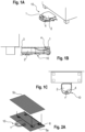
- Figure 1A shows an isometric view of a vacuum robot 10, which has a bumper 4 in the lidar sensor 1, which detects obstacles that are not themselves detected by the lidar sensor 1, but can lead to collisions with the lidar sensor 1.
- Figure 1B shows a side view of it.
- Figure 1C represents a top view of the Figures 1A, 1B represents.
- the first level 5a is filled first because the lidar sensor constantly scans the surroundings.
- obstacles are entered into the second level 5b.
- the second level 5b is only sparsely filled (see Figures 2A , 2 B ).
- the vacuum robot systematically travels over floor surfaces during cleaning trips, it comes into more and more frequent contact with obstacles 6, the lower clearance of which leads to a collision with the lidar sensor 1.
- the second level 5b is expanded and thus more true to the environment.
- the two levels of the environment map make it possible to distinguish which obstacles occur at which height level (robot height or lidar height).
- FIGs 2A to 2C show the progressive exploration of the environment and the associated progressive filling of the second level 5b.
- the vacuum robot 10 the obstacles 6 and the superimposed levels 5a, 5b of the current environment map are shown.
- Figure 2C shows the final environment map after several detections. The vacuum robot can clearly distinguish which obstacles 6 affect the device body and which obstacles 6 affect the lidar sensor.
- An optimal movement path can be carried out after the introduction of the second level 5b.
- every point to be traversed on the planned trajectory is checked in both planes 5a, 5b for each path.
- the Robot vacuum cleaner can pass all obstacles 6.
- the lidar sensor can get past the obstacles.
- separate evaluations are used, which are linked programmatically with an "AND" criterion in order to obtain a collision-free path.
- the vacuum robot 10 is able to clean specific areas under obstacles such as furniture, such as the front area under sofas or cupboards, through a targeted movement.
- Figures 3A, 3B show a standard movement pattern F, in particular driving along edges of the obstacles 6.
- the vacuum robot 10 only passes under the obstacle 6 in order to clean along the obstacle 6. Maximum cleaning, especially in areas below the obstacle 6, is therefore impossible.
- Figures 4A, 4B represent a targeted journey of the vacuum robot, which is based on the two levels of the surrounding map.
- the targeted evaluation enables special driving maneuvers in which affected floor surfaces are not only cleaned by driving along sideways, as in the Figures 3A, 3B is shown.
- the special driving maneuver includes, for example, a sawtooth pattern S, in which the vacuum robot repeatedly drives frontally under the obstacle 6, then backs up and moves under the obstacle 6 again, offset a little to the side, as shown in Figures 4A, 4B is shown. This allows the vacuum robot 10 to push its suction mouth as far back as possible under the obstacles 6, thus ensuring maximum floor cleaning even under obstacles 6.
- step 100 the vacuum robot carries out an exploration or cleaning trip.
- the vacuum robot detects an obstacle with its lidar sensor or its device bumper (step 101a) and enters this detected obstacle in the first level of the environmental map (step 102a). Recognizes If the vacuum robot encounters an obstacle with the lidar bumper (step 101b), the vacuum robot enters this detected obstacle into the second level of the environment map (step 102b).
- the vacuum robot then plans its optimal or maximum movement path depending on the first and second levels created (step 103).
- the vacuum robot checks this planned movement path on the first level of the environment map (step 104a).
- the vacuum robot checks the planned movement path on the second level of the environment map (step 104b).
- the vacuum robot follows the planned path to carry out its cleaning (step 105).
Landscapes
- Engineering & Computer Science (AREA)
- Radar, Positioning & Navigation (AREA)
- Remote Sensing (AREA)
- Physics & Mathematics (AREA)
- General Physics & Mathematics (AREA)
- Automation & Control Theory (AREA)
- Aviation & Aerospace Engineering (AREA)
- Electromagnetism (AREA)
- Control Of Position, Course, Altitude, Or Attitude Of Moving Bodies (AREA)
- Electric Vacuum Cleaner (AREA)
Abstract
Die Erfindung betrifft ein Verfahren zum Erstellen einer Umgebungskarte eines Umgebungsbereichs für den Betrieb eines mobilen, selbstfahrenden Geräts (10), insbesondere Bodenreinigungsgeräts wie einen Saug- und/oder Kehr- und/oder Wischroboter, mit den Verfahrensschritten: Detektieren des Umgebungsbereichs des Geräts (10) mit zumindest einem ersten Sensor (1) zum Erstellen einer ersten horizontalen Ebene (5a) der Umgebungskarte; Detektieren des Umgebungsbereichs des Geräts (10) mit zumindest einem zweiten Sensor (4) zum Erstellen einer zweiten horizontalen Ebene (5b) der Umgebungskarte, die sich von der ersten horizontalen Ebene (5a) unterscheidet; und Planen eines Bewegungspfades des Geräts (10) basierend auf der ersten und zweiten Ebene (5a, 5b) der Umgebungskarte, um insbesondere eine größtmögliche Bodenbearbeitung im Umgebungsbereich zu erzielen. Weiter betrifft die Erfindung ein mobiles, selbstfahrendes Gerät (10), das ein derartiges Verfahren durchführen kann.

Description
Die Erfindung betrifft ein Verfahren zum Erstellen einer Umgebungskarte eines Umgebungsbereichs für den Betrieb eines mobilen, selbstfahrenden Geräts, insbesondere Bodenreinigungsgeräts, wie einen Saug- und/oder Kehr- und/oder Wischroboter, sowie ein mobiles, selbstfahrendes Gerät, das ein derartiges Verfahren umfasst.The invention relates to a method for creating an environment map of an environmental area for the operation of a mobile, self-propelled device, in particular a floor cleaning device, such as a vacuum and/or sweeping and/or mopping robot, as well as a mobile, self-propelled device that includes such a method.
Mobile, selbstfahrende Geräte, wie beispielsweise Saugroboter, haben die Aufgabe, autonom möglichst eine gesamte Bodenfläche zu reinigen. Dafür können diese Saugroboter durch Sensoren ihre Umgebung wahrnehmen, um sich autonom zu bewegen, ohne gegen Hindernisse zu stoßen, ideale Bewegungspfade zu bestimmen und einen optimalen, insbesondere maximalen Anteil des zu reinigenden Bodenbearbeitungsbereichs zu reinigen. Neben dem für den Fachmann bekannten Bumper, der Kollisionen mit Hindernissen auf Ebene eines Gerätekörpers erfassen kann, sind die Saugroboter häufig zusätzlich mit einem Lidar-Sensor ausgestattet, der die Roboterumgebung meist mit einem 360° Sichtfeld berührungslos und in mehreren Metern Entfernung abtastet, um diese Messwerte in eine Umgebungskarte einzutragen. Die Integration des Lidar-Sensors erfolgt überwiegend in Form eines Turm-ähnlichen Aufbaus auf dem Gerätegehäuse, sodass der Lidar-Sensor ein freies Sichtfeld über dem Saugroboter-Gerätekörper hat.Mobile, self-propelled devices, such as vacuum robots, have the task of cleaning an entire floor area autonomously. To do this, these vacuum robots can use sensors to perceive their surroundings in order to move autonomously without hitting obstacles, determine ideal movement paths and clean an optimal, in particular maximum, portion of the floor processing area to be cleaned. In addition to the bumper known to experts, which can detect collisions with obstacles at the level of a device body, the vacuum robots are often also equipped with a lidar sensor, which usually scans the robot environment with a 360° field of view without contact and at a distance of several meters Enter measured values into an area map. The lidar sensor is mainly integrated in the form of a tower-like structure on the device housing, so that the lidar sensor has a clear field of view above the robot vacuum device body.
Dabei ist es möglich, dass über und/oder unter einer Mess-Ebene des Lidar-Sensors ein Umgebungsbereich verbleibt, der weder vom Lidar-Sensor noch vom Bumper erfasst wird, sodass die Gefahr besteht, dass der Saugroboter gegen Hindernisse, Gegenstände und Möbel stößt. Auch kann der Saugroboter mit dem Lidar-Turm keine Hindernisse unterfahren, die auf Höhe des Lidar-Sensors liegen. Jedoch ist es möglich, dass der Saugroboter zumindest einen Randbereich derartiger Hindernisse reinigt, insbesondere, wenn der Lidar-Turm örtlich vom Reinigungssystem entfernt auf dem Saugroboter angeordnet ist.It is possible that an environmental area remains above and/or below a measuring level of the lidar sensor that is neither detected by the lidar sensor nor the bumper, so that there is a risk that the vacuum robot will collide with obstacles, objects and furniture . The vacuum robot with the lidar tower also cannot drive under obstacles that are at the level of the lidar sensor. However, it is possible for the vacuum robot to clean at least an edge area of such obstacles, especially if the lidar tower is arranged on the vacuum robot at a location away from the cleaning system.
Es ist bekannt, den Lidar-Sensor zusätzlich mit einem separaten, dedizierten Bumper auszustatten. Wenn der Saugroboter mit seinem Lidar-Bumper gegen ein Hindernis stößt, fährt der Saugroboter nach Stand der Technik ein Stück zurück und versucht einige Zentimeter daneben erneut, ob er passieren kann. Dieses Fahrverhalten wiederholt sich solange, bis der Saugroboter einen Pfad findet, auf dem er sein Ziel erreichen kann, ohne gegen etwas zu stoßen. Ein Gedächtnis für die Bereiche, an denen der Lidar-Bumper einen Gegenstand detektiert hat, haben die herkömmlichen Saugroboter nicht. Bei einem erneuten Fahrmanöver entlang der entsprechenden Pfade stoßen die Saugroboter daher mit dem Lidar-Sensor erneut gegen das jeweilige Hindernis.It is known to additionally equip the lidar sensor with a separate, dedicated bumper. If the vacuum robot hits an obstacle with its lidar bumper, According to the state of the art, the vacuum robot moves back a little and tries again a few centimeters away to see whether it can pass. This driving behavior is repeated until the robot vacuum cleaner finds a path on which it can reach its destination without hitting anything. Conventional vacuum robots do not have a memory for the areas where the lidar bumper has detected an object. When driving again along the corresponding paths, the vacuum robots use the lidar sensor to hit the respective obstacle again.
Aufgabe der Erfindung ist es, eine Umgebungskarte erstellen zu können, die eine logische Auswertung gegebener Umgebungssituationen und insbesondere eine Vermeidung wiederholter Kollisionen bei gleichzeitigem Sicherstellen der Reinigung erreichbarer Flächen gewährleistet.The object of the invention is to be able to create an environmental map that ensures a logical evaluation of given environmental situations and in particular an avoidance of repeated collisions while at the same time ensuring that accessible areas are cleaned.
Diese Aufgabe wird durch ein Verfahren zum Erstellen einer Umgebungskarte eines Umgebungsbereichs für den Betrieb eines mobilen, selbstfahrenden Geräts mit den Merkmalen des Anspruchs 1 gelöst. Weiter wird diese Aufgabe gelöst durch ein mobiles, selbstfahrendes Gerät mit den Merkmalen des Anspruchs 10. Vorteilhafte Ausgestaltungen und Weiterbildungen sind Gegenstand der Unteransprüche.This object is achieved by a method for creating an environmental map of an environmental area for the operation of a mobile, self-propelled device with the features of claim 1. This task is further solved by a mobile, self-propelled device with the features of
Erfindungsgemäß wird bei einem Verfahren zum Erstellen einer Umgebungskarte eines Umgebungsbereichs für den Betrieb eines mobilen, selbstfahrenden Geräts, insbesondere Bodenreinigungsgeräts wie ein Saug- und/oder Kehr- und/oder Wischroboter, der Umgebungsbereich des Geräts mit zumindest einem ersten Sensor detektiert, um eine erste horizontale Ebene der Umgebungskarte zu erstellen. Weiter wird der Umgebungsbereich des Geräts mit zumindest einem zweiten Sensor detektiert, um eine zweite horizontale Ebene der Umgebungskarte zu erstellen, die sich von der ersten horizontalen Ebene unterscheidet. Ein Bewegungspfad des Geräts wird basierend auf der ersten und zweiten Ebene der Umgebungskarte geplant, um insbesondere eine größtmögliche Bodenbearbeitung im Umgebungsbereich zu erzielen.According to the invention, in a method for creating an environmental map of an environmental area for the operation of a mobile, self-propelled device, in particular a floor cleaning device such as a vacuum and/or sweeping and/or mopping robot, the surrounding area of the device is detected with at least one first sensor in order to obtain a first horizontal plane of the environment map. Furthermore, the surrounding area of the device is detected with at least a second sensor in order to create a second horizontal level of the surrounding map, which differs from the first horizontal level. A movement path of the device is planned based on the first and second levels of the surrounding map, in particular to achieve the greatest possible tillage in the surrounding area.
Vorliegend wird zur Hindernisdetektion demnach eine zweite Ebene der Umgebungskarte eingeführt, um auswerten zu können, welche Bodenbereiche für einen Gerätekörper des Geräts nicht erreichbar und somit nicht reinigbar sind, und welche Bodenbereiche ausschließlich für den ersten und/oder zweiten Sensor nicht passierbar sind. Durch geeignete Missions- und Pfadplanungen können anschließend hindernisnahe Bodenbereiche systematisch und insbesondere optimal gereinigt werden.In the present case, a second level of the environmental map is introduced for obstacle detection in order to be able to evaluate which floor areas cannot be reached by a device body of the device and therefore cannot be cleaned, and which floor areas are not passable exclusively for the first and/or second sensor. Through With appropriate mission and path planning, ground areas close to the obstacle can then be cleaned systematically and, in particular, optimally.
Beispielsweise weist der Gerätekörper eine signifikant geringere Höhe im Vergleich zum ersten und/oder zweiten Sensor auf. Der erste Sensor ist zum Beispiel ein Lidar-Sensor, der auf dem Gerätekörper in einem hinteren Bereich des Geräts angeordnet ist. Mit einem vorderen Bereich des Geräts kann dieses demnach Bodenbereiche erreichen und insbesondere auch reinigen, an denen das Gerät lediglich mit dem Lidar-Sensor mit Hindernissen kollidieren würde.For example, the device body has a significantly lower height compared to the first and/or second sensor. The first sensor is, for example, a lidar sensor which is arranged on the device body in a rear area of the device. With a front area of the device, it can therefore reach and in particular clean areas of the floor where the device would only collide with obstacles with the lidar sensor.
Diese zumindest teilweise unterfahrbaren Hindernisse werden in der zweiten Ebene der Umgebungskarte hinterlegt. Dadurch kann mit Vorteil ein wiederholtes Gegenstoßen dieser Hindernisse mit dem Lidar-Sensor gemieden werden. Eine Unterscheidung der Hindernisse auf Höhe des Gerätekörpers (erste horizontale Ebene) und Hindernisse auf Höhe des Lidar-Sensors (zweite horizontale Ebene) ermöglicht vorteilhafterweise das wiederholbare teilweise Unterfahren von Hindernissen, wodurch der erreichbare beziehungsweise reinigbare Anteil des gesamten Bodenbereichs steigt. Die gezielte Auswertung der beiden Ebenen der Umgebungskarte ermöglicht eine optimierte Planung definierter Fahrmanöver an oder entlang von Hindernissen.These at least partially passable obstacles are stored in the second level of the surrounding map. This can advantageously avoid repeated collisions with these obstacles with the lidar sensor. A distinction between the obstacles at the level of the device body (first horizontal level) and obstacles at the level of the lidar sensor (second horizontal level) advantageously enables the repeatable partial driving under obstacles, which increases the reachable or cleanable proportion of the entire floor area. The targeted evaluation of the two levels of the environmental map enables optimized planning of defined driving maneuvers on or along obstacles.
Unter einem mobilen, selbstfahrenden Gerät ist insbesondere ein Bodenreinigungsgerät zu verstehen, welches insbesondere im Haushaltsbereich Bodenflächen autonom bearbeitet. Hierunter zählen unter anderem Saug-, Wisch- und/oder Kehrroboter wie beispielsweise Staubsaugerroboter und/oder Rasenmäherroboter. Diese Geräte arbeiten im Betrieb (Reinigungs- oder Schneidebetrieb) bevorzugt ohne oder mit möglichst wenig Nutzereingriff. Beispielsweise fährt das Gerät selbsttätig in einen vorgegebenen Raum, um entsprechend einer vorgegebenen und einprogrammierten Verfahrensstrategie den Boden zu reinigen.A mobile, self-propelled device is to be understood in particular as a floor cleaning device which processes floor surfaces autonomously, particularly in the household sector. This includes, among other things, vacuum, mopping and/or sweeping robots such as vacuum cleaner robots and/or lawn mower robots. During operation (cleaning or cutting operation), these devices preferably work without or with as little user intervention as possible. For example, the device automatically moves into a specified room to clean the floor according to a specified and programmed process strategy.
Unter der zu bearbeitenden Bodenfläche ist jegliche zu reinigende Raumfläche zu verstehen. Hierunter fallen unter anderem auch Teilbereiche einzelner Räume, einzelne Flächen einer Wohnung, einzelne Räume einer Wohnung und/oder die gesamte Bodenfläche der vollständigen Wohnung beziehungsweise des Wohnraums.The floor area to be worked on is understood to mean any room area that needs to be cleaned. This also includes, among other things, partial areas of individual rooms, individual areas of an apartment, individual rooms of an apartment and/or the entire floor area of the entire apartment or living space.
Um jegliche individuellen Umgebungsbesonderheiten beachten zu können, findet bevorzugt eine Explorationsfahrt mit dem mobilen, selbstfahrenden Gerät statt. Unter einer Explorationsfahrt ist insbesondere eine Erkundungsfahrt zu verstehen, die dazu geeignet ist, eine zu bearbeitende Bodenfläche nach Hindernissen, Raumaufteilung und ähnlichem zu erkunden, und insbesondere den Umgebungsbereich des Geräts zu detektieren. Ziel einer Explorationsfahrt ist es insbesondere, Gegebenheiten des zu bearbeitenden Bodenbearbeitungsbereich einschätzen und/oder darstellen zu können.In order to be able to take into account any individual environmental characteristics, an exploration trip with the mobile, self-propelled device is preferred. An exploration trip is to be understood in particular as an exploration trip that is suitable for exploring a floor area to be worked on for obstacles, room layout and the like, and in particular for detecting the surrounding area of the device. The aim of an exploration trip is, in particular, to be able to assess and/or represent the conditions of the soil cultivation area to be worked.
Nach der Explorationsfahrt kennt das mobile, selbstfahrende Gerät seine Umgebung und kann diese in Form der Umgebungskarte an den Nutzer weitergeben, zum Beispiel in einer App an einem Mobilgerät. In der Umgebungskarte kann dem Nutzer die Möglichkeit gegeben werden, mit dem mobilen, selbstfahrenden Gerät zu interagieren. Der Nutzer kann mit Vorteil Informationen in der Umgebungskarte einsehen und bei Bedarf ändern und/oder anpassen.After the exploration trip, the mobile, self-driving device knows its surroundings and can pass this on to the user in the form of the surrounding map, for example in an app on a mobile device. In the surrounding map, the user can be given the opportunity to interact with the mobile, self-driving device. The user can advantageously view information on the surrounding map and change and/or adapt it if necessary.
Unter einer Umgebungskarte ist insbesondere jegliche Karte zu verstehen, die geeignet ist, die Umgebung des Bodenbearbeitungsbereichs mit all seinen Hindernissen und Gegenständen darzustellen. Beispielsweise zeigt die Umgebungskarte den Bodenbearbeitungsbereich mit den darin enthaltenen Möbeln und Wänden skizzenartig an. Die Umgebungskarte weist hierbei die erste und die zweite horizontale Ebene auf, die insbesondere horizontal zur Bodenfläche ausgerichtet sind und die zueinander im Wesentlichen parallel verlaufen. Jede Ebene stellt dabei die eigenen höhenrelevanten Hindernisse und Gegenstände dar, sodass sich die Ebenen zumindest bereichsweise unterscheiden.An environmental map is to be understood in particular as any map that is suitable for displaying the surroundings of the tillage area with all its obstacles and objects. For example, the environment map shows a sketch of the tillage area with the furniture and walls within it. The environment map has the first and second horizontal planes, which are aligned in particular horizontally to the floor surface and which run essentially parallel to one another. Each level represents its own height-relevant obstacles and objects, so that the levels differ at least in some areas.
Unter Hindernisse sind jegliche Objekte und/oder Gegenstände zu verstehen, die in einem Bodenbearbeitungsbereich angeordnet sind, beispielsweise dort liegen oder stehen, und die Bearbeitung durch das mobile, selbstfahrende Gerät beeinflussen, insbesondere behindern und/oder stören, wie beispielsweise Möbel, Wände, Vorhänge, Teppiche und ähnliches.Obstacles are understood to mean any objects and/or objects that are arranged in a soil processing area, for example lying or standing there, and which influence, in particular hinder and/or disrupt, the processing by the mobile, self-propelled device, such as furniture, walls, curtains , carpets and the like.
Die Umgebungskarte mit den Hindernissen wird vorzugsweise in der App an einem tragbaren Zusatzgerät dargestellt. Dies dient insbesondere der Visualisierung zu einer möglichen Interaktion für den Nutzer.The surrounding map with the obstacles is preferably displayed in the app on a portable additional device. This serves in particular to visualize possible interaction for the user.
Unter einem Zusatzgerät ist vorliegend insbesondere jegliches Gerät zu verstehen, das für einen Benutzer tragbar ist, das außerhalb des mobilen, selbstfahrenden Geräts angeordnet, insbesondere extern und/oder differenziert vom mobilen, selbstfahrenden Gerät ist, und zu einer Anzeige, Bereitstellung, Übermittlung und/oder Übertragung von Daten geeignet ist, wie beispielsweise ein Handy, ein Smartphone, ein Tablet und/oder ein Computer beziehungsweise Laptop.In the present case, an additional device is to be understood in particular as any device that is portable for a user, which is arranged outside the mobile, self-propelled device, in particular is external and/or differentiated from the mobile, self-propelled device, and is used for display, provision, transmission and/or or transmission of data, such as a cell phone, a smartphone, a tablet and/or a computer or laptop.
Auf dem tragbaren Zusatzgerät ist bevorzugt eine App, insbesondere eine Reinigungs-App, installiert, die zur Kommunikation des mobilen, selbstfahrenden Geräts mit dem Zusatzgerät dient und insbesondere eine Visualisierung des Bodenbearbeitungsbereichs, also des zu reinigenden Wohnraums oder der zu reinigenden Wohnung beziehungsweise des Wohnbereichs ermöglicht. Die App zeigt dem Nutzer dabei vorzugsweise den zu reinigenden Bereich als Umgebungskarte sowie jegliche Hindernisse an.An app, in particular a cleaning app, is preferably installed on the portable additional device, which serves to communicate between the mobile, self-propelled device and the additional device and in particular enables visualization of the floor processing area, i.e. the living space to be cleaned or the apartment or the living area to be cleaned . The app preferably shows the user the area to be cleaned as a map of the surrounding area as well as any obstacles.
Unter einem Gerätegehäuse ist insbesondere das äußere Gehäuse des Geräts zu verstehen, welches das Gerät nach außen hin abschließt. Im Inneren des Gerätegehäuses befindet sich also das Innenleben des Geräts. Der erste Sensor überragt das Gerätegehäuse, beispielsweise in vertikaler Richtung, also in Z-Richtung. Beispielsweise ist der erste Sensor auf einer Oberseite in einem hinteren oder mittigen Bereich des Gerätegehäuses angeordnet.A device housing is understood to mean, in particular, the outer housing of the device, which closes off the device from the outside. The inner workings of the device are located inside the device housing. The first sensor projects beyond the device housing, for example in the vertical direction, i.e. in the Z direction. For example, the first sensor is arranged on a top side in a rear or central area of the device housing.
Unter einem ersten und einem zweiten Sensor ist insbesondere jeglicher Sensor zu verstehen, der dazu geeignet ist, Hindernisse bevorzugt zuverlässig zu detektieren. Dieser ist vorzugsweise taktil, tastend, berührungsempfindlich, laserbasiert und/oder kamerabasiert. Vorzugsweise ist der erste Sensor ein LIDAR-Sensor und/oder ein Laserturm, der seine Umgebung in einer horizontalen Ebene durch eine 360°-Rotation abtastet beziehungsweise abscannt. Dabei werden von dem ersten Sensor in gleichmäßigen Intervallen Messstrahlen, insbesondere Laserstrahlen, ausgesendet, die für eine Entfernungsmessung Verwendung finden. Die Rotation des ersten Sensors erfolgt um eine Drehachse, insbesondere um eine z-Achse, relativ zum Gerätegehäuse und wird durch einen Motor ausgeführt. Bevorzugt ist der zweite Sensor ein Bumper, der an dem Lidar-Sensor oder auf dem Gerätekörper angeordnet ist (Lidar-Bumper). Dieser detektiert bevorzugt bei Berührung Hindernisse und Gegenstände, sodass Hindernisse auf Höhenebene des Lidar-Sensors zuverlässig erkannt werden können, auch wenn der Lidar-Sensor selbst die Hindernisse nicht erfassen kann.A first and a second sensor is understood to mean, in particular, any sensor that is suitable for preferably reliably detecting obstacles. This is preferably tactile, palpable, touch-sensitive, laser-based and/or camera-based. Preferably, the first sensor is a LIDAR sensor and/or a laser tower that scans its surroundings in a horizontal plane through a 360° rotation. The first sensor emits measuring beams, in particular laser beams, at regular intervals, which are used for distance measurement. The rotation of the first sensor takes place about an axis of rotation, in particular about a z-axis, relative to the device housing and is carried out by a motor. The second sensor is preferably a bumper that is arranged on the lidar sensor or on the device body (lidar bumper). This preferably detects obstacles and objects when touched, so that obstacles can be reliably detected at the height level of the lidar sensor, even if the lidar sensor itself cannot detect the obstacles.
Unter einer horizontalen Ebene ist insbesondere jegliche Ebene zu verstehen, die parallel zu der Bodenfläche und in horizontaler und/oder waagerechter Richtung verläuft. Insbesondere verläuft die horizontale Ebene parallel zur Oberseite des Gerätegehäuses. Vorzugsweise liegt die erste horizontale Ebene in geringem Abstand, also knapp über der Oberseite des Gerätegehäuses. Die zweite horizontale Ebene erstreckt sich vorzugsweise oberhalb der ersten Ebene auf oberster Höhe des Lidar-Sensors.A horizontal plane is to be understood in particular as meaning any plane that runs parallel to the floor surface and in a horizontal and/or horizontal direction. In particular, the horizontal plane runs parallel to the top of the device housing. The first horizontal plane is preferably at a short distance, i.e. just above the top of the device housing. The second horizontal level preferably extends above the first level at the top level of the lidar sensor.
Unter einem Bewegungspfad ist insbesondere eine geplante Fahrbewegung des Geräts zu verstehen, die als Ziel die größtmögliche Bodenbearbeitung im Umgebungsbereich des Geräts beinhaltet. Als größtmögliche Bodenbearbeitung ist dabei eine optimale Bearbeitung in einem größtmöglichen Bodenbereich zu verstehen, also auch bereichsweise unterhalb von Hindernissen und Gegenständen, falls die Gerätekörperhöhe (unabhängig von der Lidar-Sensor-Höhe) des Geräts dies zulässt.A movement path is to be understood in particular as a planned travel movement of the device, which has as its goal the greatest possible tillage in the area surrounding the device. The greatest possible soil cultivation is understood to mean optimal cultivation in the largest possible soil area, i.e. also in areas below obstacles and objects, if the device body height (regardless of the lidar sensor height) of the device allows this.
Bei einer vorteilhaften Ausführungsform werden Pfade unterhalb von zumindest bereichsweise unterfahrbaren Hindernissen im Bewegungspfad integriert. Insbesondere Bereiche unter Hindernissen, die zwar mit dem ersten Sensor, insbesondere dem Lidar-Sensor, aufgrund der Höhe des Lidar-Sensors nicht unterfahrbar sind, jedoch eine größere Höhe als das Gerätegehäuse aufweisen, und daher mit dem Gerätegehäuse unterfahrbar sind, können so bereichsweise gereinigt werden. Dabei befindet sich mit Vorteil ein Saugmund mit Bürstenwalze des Geräts, der zum Reinigen des Bodens eingesetzt wird, auf einer dem ersten Sensor gegenüberliegenden Seite des Gerätegehäuses, sodass eine optimale Reinigung des Bodens gewährleistet werden kann. Dadurch können mit dem Saugmund Bodenbereiche erreicht und gereinigt werden, an denen das Gerät mit seinem Lidar-Sensor mit dem Hindernis kollidieren würde.In an advantageous embodiment, paths are integrated into the movement path below obstacles that can be driven under at least in some areas. In particular, areas under obstacles that cannot be driven under with the first sensor, in particular the lidar sensor, due to the height of the lidar sensor, but which have a greater height than the device housing and can therefore be driven under with the device housing, can be cleaned in areas become. A suction mouth with a brush roller of the device, which is used to clean the floor, is advantageously located on a side of the device housing opposite the first sensor, so that optimal cleaning of the floor can be guaranteed. This allows the suction mouth to reach and clean floor areas where the device with its lidar sensor would collide with the obstacle.
Bei einer weiteren vorteilhaften Ausführungsform sind die erste Ebene und die zweite Ebene unterschiedliche Höhenebenen über dem Boden. Insbesondere ist die erste Ebene dem Boden nähergelegen als die zweite Ebene. Die erste Ebene beinhaltet demnach bodennähere Hindernisse als die zweite Ebene. In der ersten Ebene sind damit Hindernisse eingetragen und dargestellt, die eine geringere Höhe aufweisen als die Hindernisse der zweiten Ebene. Die Ebenen der Umgebungskarte unterscheiden sich daher inhaltlich, insbesondere durch die eingetragenen höhenunterschiedlichen Hindernisse.In a further advantageous embodiment, the first level and the second level are different height levels above the ground. In particular, the first level is closer to the ground than the second level. The first level therefore contains obstacles that are closer to the ground than the second level. In the first level, obstacles are entered and displayed that are lower in height than that Second level obstacles. The levels of the environment map therefore differ in terms of content, in particular due to the obstacles of different heights entered.
Bei einer weiteren vorteilhaften Ausführungsform enthalten die erste Ebene Hindernisse, die für einen Gerätekörper des Geräts nicht passierbar sind, und die zweite Ebene Hindernisse, die für den zweiten Sensor nicht passierbar sind. Vorzugsweise sind die Hindernisse der zweiten Ebene für den Gerätekörper passierbar. Beispielsweise werden Messergebnisse des Lidar-Sensors (erster Sensor) und/oder Kollisionsergebnisse eines Bumpers, der an einer Front des Gerätegehäuses angeordnet ist, in die erste Ebene eingetragen. In die zweite Ebene werden Kollisionsergebnisse des Lidar-Bumpers (zweiter Sensor) eingetragen. Die zwei getrennten Ebenen lassen dabei klar unterscheiden, welche Hindernisse in welcher Höhenebene (Gerätegehäuse-Höhe oder Lidar-Sensor-Höhe) auftreten.In a further advantageous embodiment, the first level contains obstacles that are not passable for a device body of the device, and the second level contains obstacles that are not passable for the second sensor. Preferably, the obstacles on the second level are passable for the device body. For example, measurement results of the lidar sensor (first sensor) and/or collision results of a bumper, which is arranged on a front of the device housing, are entered into the first level. Collision results from the lidar bumper (second sensor) are entered into the second level. The two separate levels make it possible to clearly distinguish which obstacles occur at which height level (device housing height or lidar sensor height).
Bei einer weiteren vorteilhaften Ausführungsform ist der Bewegungspfad ein kollisionsfreier Pfad. Dabei wird der Bewegungspfad bevorzugt derart geplant, dass die Hindernisse der zweiten Ebene zumindest bereichsweise von dem Gerätekörper unterfahren werden. Insbesondere wird nach dem Erstellen der zweiten Ebene eine Fahrtplanung durchgeführt, die den Bewegungspfad des Geräts erstellt. Dazu wird für einen Bewegungspfad jeder zu durchquerende Punkt auf einer der geplanten Trajektorie in beiden Ebenen der Umgebungskarte geprüft. Dabei wird in der ersten Ebene geprüft, ob der Gerätekörper Hindernisse passieren beziehungsweise unterfahren kann und in der zweiten Ebene, ob der Lidar-Sensor an den Hindernissen vorbeikommt beziehungsweise diese unterfahren kann. Die Auswertung wird hierbei beispielsweise separat durchgeführt und programmtechnisch mit einem "UND"-Kriterium verknüpft, um den kollisionsfreien Bewegungspfad zu erhalten. Diese verknüpfte Auswertung beider Ebenen ermöglicht nun, dass das Gerät automatisch maximal viel Bodenfläche mit dem Gerät befahren, unterfahren und damit reinigen und dennoch Hindernisse für den Lidar-Sensor umgehen kann.In a further advantageous embodiment, the movement path is a collision-free path. The movement path is preferably planned in such a way that the obstacles on the second level are passed under by the device body at least in some areas. In particular, after creating the second level, trip planning is performed, which creates the movement path of the device. For this purpose, each point to be crossed on one of the planned trajectory is checked in both levels of the surrounding map for a movement path. The first level checks whether the device body can pass or drive under obstacles and the second level checks whether the lidar sensor can pass or drive under the obstacles. The evaluation is carried out separately, for example, and linked in the program with an “AND” criterion in order to obtain the collision-free movement path. This linked evaluation of both levels now enables the device to automatically drive over, drive under and thus clean a maximum amount of floor space with the device and still avoid obstacles for the lidar sensor.
Bei einer weiteren vorteilhaften Ausführungsform entspricht bei dem Unterfahren der Bewegungspfad des Geräts einem Sägezahnmuster. Durch den geplanten Bewegungspfad ist das Gerät in der Lage, Bereiche unter Hindernissen, zum Beispiel Möbel, etwa vordere Bereiche unter Sofas oder Schränken, durch eine gezielte Fahrt zu reinigen. Eine gezielte Auswertung der nicht durch Standardbewegungsmuster, wie beispielsweise "entlang von Kanten fahren" oder "den Raum mit Mäandern reinigen", abgedeckten Bereiche ermöglicht unter anderem spezielle Fahrmanöver des Geräts. Teilweise unterfahrbare Bereiche werden beispielsweise nicht durch ein seitliches Entlangfahren gereinigt, sondern durch ein Sägezahnmuster, bei dem das Gerät immer wieder frontal unter das Hindernis fährt, dann zurücksetzt und ein Stück seitlich versetzt erneut unter das Hindernis fährt.In a further advantageous embodiment, the movement path of the device corresponds to a sawtooth pattern when driving under. Thanks to the planned movement path, the device is able to cover areas under obstacles, for example Clean furniture, such as front areas under sofas or cupboards, with a targeted drive. A targeted evaluation of the areas not covered by standard movement patterns, such as "moving along edges" or "cleaning the room with meanders", enables, among other things, special driving maneuvers of the device. For example, areas that are partially accessible are not cleaned by driving along sideways, but rather using a sawtooth pattern in which the device repeatedly drives under the obstacle head-on, then backs up and moves under the obstacle again, offset a little to the side.
Bei einer weiteren vorteilhaften Ausführungsform sind der erste Sensor ein Lidar-Sensor auf dem Gerätekörper und/oder ein Bumper am Gerätekörper, und der zweite Sensor ein Bumper für den Lidar-Sensor und/oder ein optischer Sensor am Lidar-Sensor. Insbesondere ist der zweite Sensor und dadurch bedingt das Erstellen der zweiten Ebene nicht auf Kollisionsereignisse mit dem ersten Sensor, also dem Lidar-Sensor, beschränkt. Auch Kamerasysteme oder andere Messsysteme auf Höhe des Lidar-Sensors können alternativ oder zusätzlich genutzt werden, um die zweite Ebene der Umgebungskarte mit Daten zu füllen und dadurch diese Ebene noch genauer zu machen. Dabei kann der zweite Sensor direkt am Lidar-Sensor oder am Gerätekörper mit Detektionshöhe der zweiten Ebene montiert beziehungsweise befestigt sein.In a further advantageous embodiment, the first sensor is a lidar sensor on the device body and/or a bumper on the device body, and the second sensor is a bumper for the lidar sensor and/or an optical sensor on the lidar sensor. In particular, the second sensor and the resulting creation of the second level are not limited to collision events with the first sensor, i.e. the lidar sensor. Camera systems or other measuring systems at the level of the lidar sensor can also be used alternatively or additionally to fill the second level of the environmental map with data and thereby make this level even more precise. The second sensor can be mounted or attached directly to the lidar sensor or to the device body with the detection height of the second level.
Weiter betrifft die Erfindung ein mobiles, selbstfahrendes Gerät, insbesondere ein Bodenreinigungsgerät zur autonomen Bearbeitung von Bodenflächen, wie einen Saug- und/oder Kehr- und/oder Wischroboter, das einen Gerätekörper, eine Auswerteeinheit, einen ersten Sensor und einen zweiten Sensor umfasst. Der erste Sensor ist auf dem Gerätekörper derart angeordnet, dass dieser eine erste horizontale Ebene eines Umgebungsbereichs detektiert. Der zweite Sensor ist an dem ersten Sensor und/oder auf dem Gerätekörper derart angeordnet, dass dieser eine zweite horizontale Ebene des Umgebungsbereichs detektiert, die sich von der ersten horizontalen Ebene unterscheidet. Die Auswerteeinheit erstellt eine Umgebungskarte basierend auf der ersten horizontalen Ebene und der zweiten horizontalen Ebene, und darauf basierend einen Bewegungspfad des Geräts mit einer größtmöglichen Bodenbearbeitung im Umgebungsbereich.The invention further relates to a mobile, self-propelled device, in particular a floor cleaning device for the autonomous processing of floor surfaces, such as a vacuum and/or sweeping and/or mopping robot, which comprises a device body, an evaluation unit, a first sensor and a second sensor. The first sensor is arranged on the device body in such a way that it detects a first horizontal plane of an surrounding area. The second sensor is arranged on the first sensor and/or on the device body in such a way that it detects a second horizontal plane of the surrounding area that differs from the first horizontal plane. The evaluation unit creates an environment map based on the first horizontal level and the second horizontal level, and based on this a movement path of the device with the greatest possible tillage in the surrounding area.
Jegliche Merkmale, Ausgestaltungen, Ausführungsformen und Vorteile das Verfahren betreffend finden auch in Zusammenhang mit dem erfindungsgemäßen Gerät Anwendung, und umgekehrt.Any features, refinements, embodiments and advantages relating to the method also apply in connection with the device according to the invention, and vice versa.
Die Erfindung wird anhand der nachfolgenden, lediglich Beispiele darstellenden Ausführungen der Erfindung näher erläutert. Es zeigen:
- Figuren 1A - 1C:
- jeweils eine schematische Ansicht eines Ausführungsbeispiels eines mobilen, selbstfahrenden Geräts, das zum Durchführen des erfindungsgemäßen Verfahrens geeignet ist,
- Figuren 2A - 2C:
- jeweils eine schematische Ansicht eines Ausführungsbeispiels eines erfindungsgemäßen Verfahrens zum Erstellen einer Umgebungskarte, und
- Figuren 3A, 3B:
- jeweils eine schematische Ansicht eines Ausführungsbeispiels eines mobilen, selbstfahrenden Geräts nach dem Stand der Technik,
- Figuren 4A, 4B:
- jeweils eine schematische Ansicht eines Ausführungsbeispiels eines mobilen, selbstfahrenden Geräts, das zum Durchführen des erfindungsgemäßen Verfahrens geeignet ist, und
- Figur 5:
- ein Ablaufdiagramm eines Ausführungsbeispiels eines erfindungsgemäßen Verfahrens zum Erstellen einer Umgebungskarte.
- Figures 1A - 1C:
- each a schematic view of an exemplary embodiment of a mobile, self-propelled device that is suitable for carrying out the method according to the invention,
- Figures 2A - 2C:
- each a schematic view of an exemplary embodiment of a method according to the invention for creating an environment map, and
- Figures 3A, 3B:
- each a schematic view of an exemplary embodiment of a mobile, self-propelled device according to the prior art,
- Figures 4A, 4B:
- each a schematic view of an exemplary embodiment of a mobile, self-propelled device that is suitable for carrying out the method according to the invention, and
- Figure 5:
- a flowchart of an exemplary embodiment of a method according to the invention for creating an environment map.
In den
Neben dem Lidar-Sensor 2 kann der Saugroboter 10 einen Bumper am Gerätekörper 2 aufweisen (nicht dargestellt). Dieser Gerätebumper detektiert Hindernisse und Gegenstände, die unterhalb der Messebene des Lidar-Sensors 1 liegen. Insbesondere stößt der Gerätebumper gegen Gegenstände und Möbel, die vorher nicht vom Lidar-Sensor 1 erfasst worden sind, also insbesondere sehr flach ausgebildete Hindernisse, wie beispielsweise Schuhe, Spielzeug, Fußleisten und ähnliches.In addition to the lidar sensor 2, the
Auch wenn der Saugroboter 10 mit seinem Lidar-Sensor 1 nicht alle Hindernisse vollständig unterfahren kann, unter die ein Saugroboter ohne vergleichbaren Turmaufbau fahren kann, ist es dennoch möglich, dass der Saugroboter 10 zumindest Randbereiche unterhalb der Hindernisse reinigt, die zwar zu niedrig für den Lidar-Sensor 1, nicht jedoch für den Gerätekörper 2 sind. Damit dabei die Reinigung gezielt, systematisch und insbesondere maximal erfolgt, werden die Messwerte der einzelnen Hindernissensoren entsprechend ausgewertet.Even if the
Insbesondere weist der Saugroboter 10 hierfür einen zweiten Sensor auf, der als Bumper am Lidar-Sensor ausgebildet ist (Lidar-Bumper 4). Dieser Lidar-Bumper 4 detektiert Hindernisse der Umgebung, die oberhalb der ersten Ebene 3 in einer zweiten Ebene angeordnet sind. Die zweite Ebene wird als weitere Ebene in die Umgebungskarte eingegliedert. Diese zweite Ebene umfasst dabei nur Messwerte, die von dem Lidar-Bumper 4 detektiert worden sind. In Kombination mit der ersten Ebene, die die Messwerte des Gerätebumpers und/oder des Lidar-Sensors umfasst, kann mit Vorteil nicht nur ausgewertet werden, wo der Saugroboter 10 keinen Bewegungspfad entlang planen kann, da er gegen ein Hindernis stoßen würde, sondern auch, wie der Saugroboter 10 fahren muss, um möglichst systematisch und maximal unter einem teilweise unterfahrbaren Hindernis zu reinigen.In particular, the
In den
Bei einer Explorationsfahrt wird zunächst die erste Ebene 5a gefüllt, da der Lidar-Sensor ständig die Umgebung abtastet. Bei Kontakt eines Hindernisses mit dem Lidar-Bumper werden Hindernisse in die zweite Ebene 5b eingetragen. Zu Beginn der Explorationsfahrt ist die zweite Ebene 5b nur spärlich gefüllt (siehe
Die
Ein optimaler Bewegungspfad kann nach Einführung der zweiten Ebene 5b durchgeführt werden. Dazu wird für jeden Pfad jeder zu durchquerende Punkt auf der geplanten Trajektorie in beiden Ebenen 5a, 5b geprüft. In der ersten Ebene 5a wird geprüft, ob der Saugroboter alle Hindernisse 6 passieren kann. In der zweiten Ebene 5b wird geprüft, ob der Lidar-Sensor an den Hindernissen vorbeikommt. Beispielsweise finden zur optimalen Bewegungspfad-Planung separate Auswertungen Anwendung, die programmtechnisch mit einem "UND"-Kriterium verknüpft werden, um einen kollisionsfreien Pfad zu erhalten. Diese gemeinsame Auswertung beider Ebenen 5a, 5b ermöglicht mit Vorteil, dass der Saugroboter automatisch maximal viel Bodenfläche befahren und insbesondere reinigen kann, und dabei dennoch Hindernisse 6 für den Lidar-Sensor umgehen kann.An optimal movement path can be carried out after the introduction of the
Als Ergebnis ist der Saugroboter 10 dadurch in der Lage, spezielle Bereiche unter Hindernissen wie Möbeln, etwa den vorderen Bereich unter Sofas oder Schränken, durch eine gezielte Fahrt zu reinigen.As a result, the
In
Claims (10)
Applications Claiming Priority (1)
| Application Number | Priority Date | Filing Date | Title |
|---|---|---|---|
| DE102022208869.7A DE102022208869A1 (en) | 2022-08-26 | 2022-08-26 | Method for creating an area map |
Publications (1)
| Publication Number | Publication Date |
|---|---|
| EP4328701A1 true EP4328701A1 (en) | 2024-02-28 |
Family
ID=87519966
Family Applications (1)
| Application Number | Title | Priority Date | Filing Date |
|---|---|---|---|
| EP23188509.6A Pending EP4328701A1 (en) | 2022-08-26 | 2023-07-28 | Method for creating an environment map |
Country Status (4)
| Country | Link |
|---|---|
| US (1) | US20240069565A1 (en) |
| EP (1) | EP4328701A1 (en) |
| CN (1) | CN117643439A (en) |
| DE (1) | DE102022208869A1 (en) |
Citations (4)
| Publication number | Priority date | Publication date | Assignee | Title |
|---|---|---|---|---|
| US5684695A (en) * | 1994-03-11 | 1997-11-04 | Siemens Aktiengesellschaft | Method and apparatus for constructing an environment map of a self-propelled, mobile unit |
| US20160027207A1 (en) * | 2014-07-22 | 2016-01-28 | Vorwerk & Co. Interholding Gmbh | Method for cleaning or processing a room by means of an autonomously mobile device |
| EP3549726A2 (en) * | 2016-11-30 | 2019-10-09 | Yujin Robot Co., Ltd. | Robotic vacuum cleaner, cleaning function control apparatus equipped in robotic vacuum cleaner, and multi-channel lidar-based obstacle detection apparatus equipped in robotic vacuum cleaner |
| US20200272165A1 (en) * | 2017-11-14 | 2020-08-27 | Positec Power Tools (Suzhou) Co., Ltd | Self-moving apparatus and method for controlling same |
Family Cites Families (3)
| Publication number | Priority date | Publication date | Assignee | Title |
|---|---|---|---|---|
| DE102016124856A1 (en) | 2016-12-19 | 2018-06-21 | Vorwerk & Co. Interholding Gmbh | Method for creating an environment map for a processing device |
| DE102017220180A1 (en) | 2017-11-13 | 2019-05-16 | BSH Hausgeräte GmbH | Create an environment map |
| CN108125622A (en) | 2017-12-15 | 2018-06-08 | 珊口(上海)智能科技有限公司 | Control method, system and the clean robot being applicable in |
-
2022
- 2022-08-26 DE DE102022208869.7A patent/DE102022208869A1/en active Pending
-
2023
- 2023-07-28 EP EP23188509.6A patent/EP4328701A1/en active Pending
- 2023-08-10 US US18/447,337 patent/US20240069565A1/en active Pending
- 2023-08-25 CN CN202311087196.8A patent/CN117643439A/en active Pending
Patent Citations (4)
| Publication number | Priority date | Publication date | Assignee | Title |
|---|---|---|---|---|
| US5684695A (en) * | 1994-03-11 | 1997-11-04 | Siemens Aktiengesellschaft | Method and apparatus for constructing an environment map of a self-propelled, mobile unit |
| US20160027207A1 (en) * | 2014-07-22 | 2016-01-28 | Vorwerk & Co. Interholding Gmbh | Method for cleaning or processing a room by means of an autonomously mobile device |
| EP3549726A2 (en) * | 2016-11-30 | 2019-10-09 | Yujin Robot Co., Ltd. | Robotic vacuum cleaner, cleaning function control apparatus equipped in robotic vacuum cleaner, and multi-channel lidar-based obstacle detection apparatus equipped in robotic vacuum cleaner |
| US20200272165A1 (en) * | 2017-11-14 | 2020-08-27 | Positec Power Tools (Suzhou) Co., Ltd | Self-moving apparatus and method for controlling same |
Also Published As
| Publication number | Publication date |
|---|---|
| DE102022208869A1 (en) | 2024-02-29 |
| US20240069565A1 (en) | 2024-02-29 |
| CN117643439A (en) | 2024-03-05 |
Similar Documents
| Publication | Publication Date | Title |
|---|---|---|
| EP3545379B1 (en) | Floor treatment machine and method for treating floor surfaces | |
| DE102014012811B4 (en) | Floor cleaning apparatus and method and system for determining a floor plan by a self-propelled floor cleaning device | |
| EP3417350B1 (en) | Method for controlling an autonomous mobile robot | |
| DE102015119865B4 (en) | Robot-assisted processing of a surface using a robot | |
| EP2710944B1 (en) | Self-propelled floor cleaning apparatus and method for operating a floor cleaning apparatus | |
| EP3441840B1 (en) | Method for operating a self-propelled cleaning device | |
| EP3139806B1 (en) | Self driving and self steering floor cleaning device and method for cleaning a floor surface | |
| EP3408719A1 (en) | Method for creating an environment map for an automatically moveable processing device | |
| EP2752726A1 (en) | Floor treatment machine and method for treating floor surfaces | |
| EP3355147B1 (en) | Method for operating an automatically moving vehicle | |
| DE102017103986A1 (en) | Method for operating a self-propelled robot | |
| WO2017089140A1 (en) | Floor-cleaning system and method for cleaning a floor surface | |
| WO2019097012A1 (en) | Floor treatment by means of an autonomous mobile robot | |
| EP4328701A1 (en) | Method for creating an environment map | |
| EP3825802B1 (en) | System with at least two automatic cleaning robots and method of operating the said system | |
| DE102021202514B4 (en) | Mobile, self-propelled device | |
| EP3848770B1 (en) | Method for operating a system with at least two automatically moving soil working devices and system for carrying out such a method | |
| EP4039162A1 (en) | Environment cleaning system | |
| EP3984434B1 (en) | Method for operating a self-propelled mobile device | |
| EP4016226B1 (en) | Method for operating a self-propelled mobile device | |
| DE102021206142A1 (en) | Mobile, self-propelled device | |
| DE102022207500B3 (en) | Method for operating a mobile, self-propelled device | |
| EP4116788A1 (en) | Automatic soil preparation equipment | |
| EP4364630A1 (en) | Method for operating a mobile self-propelled device | |
| DE102022123089A1 (en) | Method for operating a self-propelled cleaning device and self-propelled cleaning device |
Legal Events
| Date | Code | Title | Description |
|---|---|---|---|
| PUAI | Public reference made under article 153(3) epc to a published international application that has entered the european phase |
Free format text: ORIGINAL CODE: 0009012 |
|
| STAA | Information on the status of an ep patent application or granted ep patent |
Free format text: STATUS: THE APPLICATION HAS BEEN PUBLISHED |
|
| AK | Designated contracting states |
Kind code of ref document: A1 Designated state(s): AL AT BE BG CH CY CZ DE DK EE ES FI FR GB GR HR HU IE IS IT LI LT LU LV MC ME MK MT NL NO PL PT RO RS SE SI SK SM TR |