EP4117495B1 - Cleaning device, in particular for robotic vacuum cleaners - Google Patents
Cleaning device, in particular for robotic vacuum cleaners Download PDFInfo
- Publication number
- EP4117495B1 EP4117495B1 EP21707892.2A EP21707892A EP4117495B1 EP 4117495 B1 EP4117495 B1 EP 4117495B1 EP 21707892 A EP21707892 A EP 21707892A EP 4117495 B1 EP4117495 B1 EP 4117495B1
- Authority
- EP
- European Patent Office
- Prior art keywords
- robotic vacuum
- air
- nozzle
- cleaning device
- flow
- Prior art date
- Legal status (The legal status is an assumption and is not a legal conclusion. Google has not performed a legal analysis and makes no representation as to the accuracy of the status listed.)
- Active
Links
- 238000004140 cleaning Methods 0.000 title claims description 39
- 238000013459 approach Methods 0.000 claims description 8
- 230000008878 coupling Effects 0.000 claims description 7
- 238000010168 coupling process Methods 0.000 claims description 7
- 238000005859 coupling reaction Methods 0.000 claims description 7
- 230000007423 decrease Effects 0.000 claims description 5
- 239000003570 air Substances 0.000 description 145
- 239000002245 particle Substances 0.000 description 27
- 230000003068 static effect Effects 0.000 description 18
- 230000000694 effects Effects 0.000 description 14
- 239000012535 impurity Substances 0.000 description 10
- 239000000428 dust Substances 0.000 description 8
- 210000004209 hair Anatomy 0.000 description 5
- 230000008859 change Effects 0.000 description 4
- 239000012080 ambient air Substances 0.000 description 3
- 238000010276 construction Methods 0.000 description 3
- 238000000926 separation method Methods 0.000 description 3
- 230000007704 transition Effects 0.000 description 3
- 230000032258 transport Effects 0.000 description 3
- 230000015572 biosynthetic process Effects 0.000 description 2
- 238000007664 blowing Methods 0.000 description 2
- 238000005755 formation reaction Methods 0.000 description 2
- 230000005484 gravity Effects 0.000 description 2
- 230000035515 penetration Effects 0.000 description 2
- 230000035699 permeability Effects 0.000 description 2
- 238000007789 sealing Methods 0.000 description 2
- 238000007493 shaping process Methods 0.000 description 2
- 239000007787 solid Substances 0.000 description 2
- 230000002195 synergetic effect Effects 0.000 description 2
- 230000001133 acceleration Effects 0.000 description 1
- 238000013473 artificial intelligence Methods 0.000 description 1
- 238000005452 bending Methods 0.000 description 1
- 230000001914 calming effect Effects 0.000 description 1
- 238000001816 cooling Methods 0.000 description 1
- 230000036541 health Effects 0.000 description 1
- 239000010954 inorganic particle Substances 0.000 description 1
- 238000009434 installation Methods 0.000 description 1
- 230000003993 interaction Effects 0.000 description 1
- 230000007246 mechanism Effects 0.000 description 1
- 239000011146 organic particle Substances 0.000 description 1
- 230000008092 positive effect Effects 0.000 description 1
- 230000000284 resting effect Effects 0.000 description 1
- 238000010079 rubber tapping Methods 0.000 description 1
- 229920006395 saturated elastomer Polymers 0.000 description 1
- 239000000725 suspension Substances 0.000 description 1
- 230000009044 synergistic interaction Effects 0.000 description 1
- 230000009466 transformation Effects 0.000 description 1
- 238000005406 washing Methods 0.000 description 1
- 238000004804 winding Methods 0.000 description 1
Images


Classifications
-
- A—HUMAN NECESSITIES
- A47—FURNITURE; DOMESTIC ARTICLES OR APPLIANCES; COFFEE MILLS; SPICE MILLS; SUCTION CLEANERS IN GENERAL
- A47L—DOMESTIC WASHING OR CLEANING; SUCTION CLEANERS IN GENERAL
- A47L9/00—Details or accessories of suction cleaners, e.g. mechanical means for controlling the suction or for effecting pulsating action; Storing devices specially adapted to suction cleaners or parts thereof; Carrying-vehicles specially adapted for suction cleaners
- A47L9/02—Nozzles
- A47L9/06—Nozzles with fixed, e.g. adjustably fixed brushes or the like
- A47L9/0693—Specially shaped nozzles, e.g. for cleaning radiators, tubes, fans or the like; Dusters
-
- A—HUMAN NECESSITIES
- A47—FURNITURE; DOMESTIC ARTICLES OR APPLIANCES; COFFEE MILLS; SPICE MILLS; SUCTION CLEANERS IN GENERAL
- A47L—DOMESTIC WASHING OR CLEANING; SUCTION CLEANERS IN GENERAL
- A47L9/00—Details or accessories of suction cleaners, e.g. mechanical means for controlling the suction or for effecting pulsating action; Storing devices specially adapted to suction cleaners or parts thereof; Carrying-vehicles specially adapted for suction cleaners
- A47L9/02—Nozzles
- A47L9/04—Nozzles with driven brushes or agitators
-
- A—HUMAN NECESSITIES
- A47—FURNITURE; DOMESTIC ARTICLES OR APPLIANCES; COFFEE MILLS; SPICE MILLS; SUCTION CLEANERS IN GENERAL
- A47L—DOMESTIC WASHING OR CLEANING; SUCTION CLEANERS IN GENERAL
- A47L9/00—Details or accessories of suction cleaners, e.g. mechanical means for controlling the suction or for effecting pulsating action; Storing devices specially adapted to suction cleaners or parts thereof; Carrying-vehicles specially adapted for suction cleaners
- A47L9/02—Nozzles
-
- A—HUMAN NECESSITIES
- A47—FURNITURE; DOMESTIC ARTICLES OR APPLIANCES; COFFEE MILLS; SPICE MILLS; SUCTION CLEANERS IN GENERAL
- A47L—DOMESTIC WASHING OR CLEANING; SUCTION CLEANERS IN GENERAL
- A47L5/00—Structural features of suction cleaners
- A47L5/12—Structural features of suction cleaners with power-driven air-pumps or air-compressors, e.g. driven by motor vehicle engine vacuum
- A47L5/22—Structural features of suction cleaners with power-driven air-pumps or air-compressors, e.g. driven by motor vehicle engine vacuum with rotary fans
-
- A—HUMAN NECESSITIES
- A47—FURNITURE; DOMESTIC ARTICLES OR APPLIANCES; COFFEE MILLS; SPICE MILLS; SUCTION CLEANERS IN GENERAL
- A47L—DOMESTIC WASHING OR CLEANING; SUCTION CLEANERS IN GENERAL
- A47L9/00—Details or accessories of suction cleaners, e.g. mechanical means for controlling the suction or for effecting pulsating action; Storing devices specially adapted to suction cleaners or parts thereof; Carrying-vehicles specially adapted for suction cleaners
- A47L9/02—Nozzles
- A47L9/04—Nozzles with driven brushes or agitators
- A47L9/0461—Dust-loosening tools, e.g. agitators, brushes
- A47L9/0466—Rotating tools
- A47L9/0477—Rolls
-
- A—HUMAN NECESSITIES
- A47—FURNITURE; DOMESTIC ARTICLES OR APPLIANCES; COFFEE MILLS; SPICE MILLS; SUCTION CLEANERS IN GENERAL
- A47L—DOMESTIC WASHING OR CLEANING; SUCTION CLEANERS IN GENERAL
- A47L9/00—Details or accessories of suction cleaners, e.g. mechanical means for controlling the suction or for effecting pulsating action; Storing devices specially adapted to suction cleaners or parts thereof; Carrying-vehicles specially adapted for suction cleaners
- A47L9/02—Nozzles
- A47L9/06—Nozzles with fixed, e.g. adjustably fixed brushes or the like
- A47L9/068—Nozzles combined with a different cleaning side, e.g. duplex nozzles or dual purpose nozzles
-
- A—HUMAN NECESSITIES
- A47—FURNITURE; DOMESTIC ARTICLES OR APPLIANCES; COFFEE MILLS; SPICE MILLS; SUCTION CLEANERS IN GENERAL
- A47L—DOMESTIC WASHING OR CLEANING; SUCTION CLEANERS IN GENERAL
- A47L9/00—Details or accessories of suction cleaners, e.g. mechanical means for controlling the suction or for effecting pulsating action; Storing devices specially adapted to suction cleaners or parts thereof; Carrying-vehicles specially adapted for suction cleaners
- A47L9/22—Mountings for motor fan assemblies
-
- A—HUMAN NECESSITIES
- A47—FURNITURE; DOMESTIC ARTICLES OR APPLIANCES; COFFEE MILLS; SPICE MILLS; SUCTION CLEANERS IN GENERAL
- A47L—DOMESTIC WASHING OR CLEANING; SUCTION CLEANERS IN GENERAL
- A47L2201/00—Robotic cleaning machines, i.e. with automatic control of the travelling movement or the cleaning operation
Definitions
- the invention relates to a cleaning device, in particular for a robotic vacuum cleaner, which ensures the supply of fast-flowing air from a spiral housing of a centrifugal fan of a robotic vacuum cleaner directly to the floor surface.
- Some of these solutions such as a rotary laser range finder and a computer that calculates the current position of the robotic vacuum cleaner based on measured changes in distance from objects in the cleaned space, consume about the same amount of energy as all other activities combined, in particular drive wheel drive, fan drive and of all brushes.
- the interior of the robotic vacuum cleaner is fundamentally dictated by its external dimensions, which must allow cleaning in restricted conditions, for example between the legs of chairs and under furniture.
- the restricted internal space limits the dimensions of the components that must fit in a robotic vacuum cleaner, and, in addition, most components must be in a location designated by functional reasons, and even the battery must be in a location acceptable for balancing the robot.
- the collection container for cleaned dirt must also have a certain minimum volume.
- the parameters of the elements that participate in the cleaning activities themselves are very limited and cannot compete comparisons with the parameters and energy sources of normal vacuum cleaners.
- the normal power input is 1.000 W and the static negative pressure generated is about 20.000 Pa.
- the power consumption of the fan corresponds to about 6 - 20 W and generates about 500 - 2.000 Pa.
- the robotic vacuum cleaner uses a pair of counter-rotating rotary feed brushes with a separate suction nozzle.
- a pair of counter-rotating brushes mechanically removes coarse dirt from the floor surface and uses the kinetic energy mechanically imparted to the dirt to transfer it to the collection container.
- Behind the pair of brushes is designed a narrow suction nozzle formed by a pair of elastic elements, which reaches just above the cleaned surface, and the sucked fine dirt is pneumatically discharged into a separate sealed collection container.
- Dirt has dimensions up to units of mm and unlike by normal vacuum cleaners, this fact must be taken into account by the suction device of robotic vacuum cleaners.
- the suction device of robotic vacuum cleaners When a person vacuuming the floor sees a crumb, the person simply raises the nozzle and then continues again with the nozzle resting on the surface.
- the robotic vacuum cleaner must clean everything that passes under the frame of the robotic vacuum cleaner, i.e. all dirt from dust in the size of microns to those 8 mm clearance.
- the construction of the suction nozzle and the dimensions of the air duct, through which the dirt is transported to the collection container, must correspond to this. In practice, this means that the minimum size of the suction nozzle must be 8 mm, and this also applies to the air duct.
- the suction nozzle must be open from the front side to allow large impurities to pass through and so, paradoxically, although their volume share in the total volume of impurities is only in the order of percent, the need to clean them makes it impossible to create a narrow joint and thus achieve high flow rates, necessary to remove fine dust particles.
- the third design approach is based on a rotating brush, which is located in the vacuum section of the air duct.
- the rotary brush driven by the electric motor is partially encapsulated and an air duct with negative air pressure opens into the housing. Behind the brush a screen is located that extends just above the floor surface.
- Particles of sufficient density and size are hit on the floor by brush blades, transported to the brush shaft and ejected by centrifugal force into the air duct and further into the collecting container. Particles of lower density and fine dust are conveyed to the collecting container by a stream of air, which partially flows around the brush and which is sucked in at the floor.
- the air flow rate on the floor is defined by the circumferential speed of the brush and only slightly exceeds it due to the residual flow between the brush blades and the brush housing.
- the circumferential speed of the brush in a robotic vacuum cleaner is usually 2 meters per second, with a diameter of usually 40 mm and 17 revolutions per second. In the case of a mechanical tool, this speed is sufficient to remove larger impurities, but in the case of air flow it is completely insufficient to separate the impurities from the surface.
- the air flow in this construction does not serve as one of the primary tools for cleaning the surface, but only as an auxiliary means for the removal and transport of fine dust blown by the brush into the collection container.
- This design also suffers from winding the hair around the brush because the surrounding flow is too slow.
- a fourth possibility of the prior art is a solution which is based on a pair of profiled counter-rotating elastic cylinders located in a vacuum air duct, which at the same time forms a suction nozzle.
- the air duct is characterized by sudden changes in cross-section, which causes turbulent flow around the profiled cylinders and problematic sealing of the profiled rotating cylinders.
- the clearance height of the robotic vacuum cleaner changes due to the high surface load of the drive wheels and thus the geometry of the suction device with respect to the floor changes.
- the roller profiles sit completely down on the carpet surface and there is a further increase in turbulent flow in the remaining holes between the rollers and the floor. The flow velocity in the remaining holes at the floor was measured at 2 m / s.
- the invention is based on a design which aims to supply fast-flowing air from a spiral housing or at least one side duct of a centrifugal fan directly to the floor surface, the essence of which consists in that a convex transfer surface is arranged between the flat nozzle and the rotary brush.
- the flat nozzle is formed as a multichannel nozzle between the convex transfer surface and the apron with an inclination of the multichannel nozzle orifice in the range of 20 to 60 degrees from the horizontal plane, the clearance height between the convex transfer surface and the floor being in the range of 1 to 8 millimetres.
- the convex transfer surface behind the mouth of the flat nozzle continues with a rounded approach and ends with a raised trailing edge, which is part of the rotating brush housing.
- the flat nozzle is continuously connected to the spiral housing of the centrifugal fan or at least one side duct by means of a multi-channel air flow straightener, the number of ducts of which connects to a system of individual air ducts that terminate at the inlet to the multi-channel nozzle.
- the cross section of the multichannel nozzle decreases in the range between the mouth of the system of individual air ducts in the multichannel nozzle and the mouth of the multichannel nozzle.
- the apron is rounded toward the floor from the multi-channel nozzle moth with a maximum clearance height in the range of 0.5 to 2 millimetres and is less than the clearance height of the convex transfer surface at the lowest point relative to the floor surface.
- the rotary brush is housed in a housing, which is followed by a vacuum section of the air duct, which is connected by an elastic coupling to the housing of the collecting container.
- the rotary brush is housed in the housing between the vacuum section of the air duct, which is connected by an elastic coupling to the housing of the collecting container and the overpressure high-speed part of the air duct of the robotic vacuum cleaner flowing around the floor surface.
- the sum of the cross-sections of the outlets of the overpressure air ducts of the high-speed part of the air duct is 3 to 40% of the cross-section of the vacuum section of the air duct.
- the cleaning device is suspended on parallel pivoting arms mounted on pins, which are pivotably mounted in lugs anchored to the structure of the robotic vacuum cleaner.
- a flat supply channel or at least one side supply channel is arranged between the flat nozzle and the centrifugal fan.
- the invention provides a sufficient flow at a given flow rate, while the sufficiently low hydraulic dimension of the individual air ducts creates the conditions for laminar flow. This minimizes energy losses and flow velocities caused by turbulent flow, the flow is evenly distributed along the entire convex transfer surface, and sharp bends in the ducts and abrupt changes in their cross-section are thus eliminated.
- the air duct assembly continuously connects the spiral housing outlet of the centrifugal fan to a corresponding small diameter air duct assembly, thereby calming the turbulent flow from the spiral housing outlet of the centrifugal fan. This ensures a smooth physical transition between the different cross-sections and shapes of the spiral housing outlet and the small diameter air ducts, as well as a smooth transition between turbulent air flow from the spiral housing outlet of the centrifugal fan and laminar flow in the small diameter ducts.
- the centrifugal fan with a spiral housing can be replaced by a centrifugal fan with at least one side channel, which is an optimal way to transform the kinetic energy of the air, which is obtained from the blades of a rotating impeller, into static energy.
- the efficiency of the side channel design is significantly higher in the transformation of kinetic energy into static energy than in the use of spiral housings, while minimizing the external dimensions of the centrifugal fan.
- the convex transfer surface feeds the high velocity flow layer from the flat multi-channel outlet nozzle to the floor surface.
- the flowing high-velocity flow layer changes the flowing convex transfer surface to the floor surface because the direction of the static pressure differential that presses the high-velocity flow layer against said surfaces changes.
- Bringing the high-velocity air layer to the floor surface parallel to the floor surface prevents contaminated air from escaping, unlike the sloping direct air flow, because the kinetic pressure in the air layer flowing parallel to the floor means lower static pressure than the surrounding atmosphere. Therefore, air contaminated with dirt cannot escape to the surroundings.
- the prior art is also improved by using a significantly simpler nozzle and air duct design, which can be a mere slit, and also by using simpler and cheaper centrifugal fans, which are designed for lower speeds, which reduces the demand on the mounting of the centrifugal fan impeller, its cooling and balancing.
- the air flowing rapidly above the surface generates an area of lower static pressure above the surface than below it, namely, for example, between the fibres of the carpet. This creates the desired upward suction, which releases and transports dirt particles from the space between the carpet fibres to the high-speed flow and further to the collecting container.
- Unwanted blowing of dirt from the floor surface is thus avoided if some or all of the convex transfer surface moves away from the floor, for example when crossing between different types of floor coverings, more than the thickness of the flowing layer of the high-speed air stream.
- the flow around the surface is completed up to the trailing edge of the convex transfer surface and the air flow is discharged into the space of the rotary brush, slowed down and discharged into the collecting container.
- the convex shape of the transfer surface ensures smooth overcoming of protruding surfaces, such as carpet edges or door sills, and therefore the convex transfer surface can be placed just above the floor and high-velocity flow in a thin layer just above the surface, which is energy efficient.
- the working distance between the lowest point of the convex transfer surface and the floor surface is in direct proportion to the vertical dimension of the flat multi-channel nozzle from which the high velocity air jet layer is discharged to the convex transfer surface and the trajectory through which where the current changes the flowed area.
- the flow of the convex transfer surface is completed only at the trailing edge of the convex transfer surface, defined by the intersection of the convex transfer surface and the inner surface of the rotary brush case and the air stream is discharged into the space of the rotating brush, slowed down and taken to a collecting container.
- An important aspect is the relationship between the circumferential speed of the rotary brush and the flow rate flowing around the convex transfer surface, which is provided by the control unit.
- the aim is to maintain a dynamic balance in terms of the mechanical effect of the rotary brush on the dirt particles and the opposite aerodynamic effect of high velocity flow and to maintain a dynamic balance between the volume and velocity of air escaping under the rotary brush and the velocity of particles accelerated by the rotary brush towards the joint. More precisely, the velocity of the air escaping under the brush must slow down to zero even below the body of the robotic vacuum cleaner and no particles must penetrate below the convex transfer surface against the air flow.
- the rotary brush acts as a flow rate equalizer in the overpressure and low-pressure branches of the air ducts.
- the high-velocity flow from the convex transfer surface moves the particles from the floor surface and subsequently this air, saturated with dirt particles, is forcibly decelerated in temporarily formed chambers between the rotary blade blades to the speed in the suction low-pressure branch to avoid problems with the air flow velocity differential in both branches of the air ducts.
- the apron with side plates enclosing the space behind the flat multichannel nozzle with a convex transfer surface with a distance from the floor surface less than the distance of the convex transfer surface from the floor surface limits the amount of air that can be sucked from the ambient atmosphere into the reduced pressure area due to high velocity flow from flat nozzles and bypassing the cylindrical convex transfer surface.
- reducing the intake air content reduces the problem of maintaining a constant volume of air and reduces the deceleration and growth of the air layer that flows around the cylindrical convex transfer surface, which results in increased floor surface cleaning efficiency.
- the apron is designed as an aid to ensure a minimum distance between the lower surface edge of the convex transfer surface and the floor surface, thus ensuring the proper function of the air flow below the convex transfer surface.
- the entire cleaning device including the convex transfer surface, the flat multi-channel nozzle, the apron with side plates reducing air intake, the rotary brush with the motor and gearbox, the rotary brush chamber with the vacuum air duct, is connected to the collecting container housing by an elastic transition element and suspended on parallel pivoted arms mounted on the pins on the frame of the robotic vacuum cleaner.
- This solution compensates changes in the ground clearance of the robotic vacuum cleaner that occur due to the different hardness of the surfaces on which the robotic vacuum cleaner works, i.e. on a wooden floor or a soft carpet.
- the usual difference in ground clearance is up to 3 - 4 mm.
- Maintaining a constant preset clearance height at the lowest edge of the convex transfer surface above the floor surface is important to ensure proper airflow transfer function from the convex transfer surface to the floor surface. This prevents excessive friction and unwanted bending of the rotary brush blades, thus protecting the motor and saving energy, protecting the carpet from excessive wear due to the rotary brush and assisting navigation systems by not introducing unnecessary accelerations that have to be evaluated by robotic vacuum cleaner navigation systems.
- a centrifugal high-speed fan with backward curved blades, a semi-closed impeller and a spiral housing produces a high static pressure air flow even at the cost of a lower flow rate.
- One of the basic ideas of the present invention is a differentiated approach to removing different categories of surface impurities.
- the primary role of the air flow is to remove fine dust particles for which the high-velocity flow is best suited. If the typical size of these particles, which is measured in micrometers, is taken into account, the decisive factor is not the power of the flow rate or the thickness of the layer of air flowing over the surface to be cleaned. Therefore, a thin layer in the range of 1 - 2 mm is completely sufficient to remove said particles from the surface and from the space between the carpet fibres.
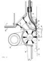
- FIG. 1 shows a partial section of a robotic vacuum cleaner in axonometric view showing the location of key features of the invention
- Fig. 2 shows a partial section of a robotic vacuum cleaner showing the position of a cleaning device
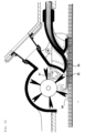
- Fig. 3 shows a partial section of a robotic vacuum cleaner indicating the position of the cleaning device when the robotic vacuum cleaner is driving on a soft surface
- Fig. 4 shows a detailed section of a robotic vacuum cleaner cleaning device with a rotary brush, a rotary brush housing, a flat multi-channel nozzle, an apron with side plates and a vertically movable hinge
- Fig. 1 shows a partial section of a robotic vacuum cleaner in axonometric view showing the location of key features of the invention
- Fig. 2 shows a partial section of a robotic vacuum cleaner showing the position of a cleaning device
- Fig. 3 shows a partial section of a robotic vacuum cleaner indicating the position of the cleaning device when the robotic vacuum cleaner is driving on a soft surface
- Fig. 4
- FIG. 5 shows a detailed section of the cleaning device indicating the air flow under the rotary brush blades
- Fig. 6 shows schematically the dependence of the change in flow speed on time and the size of the slit under the rotary brush blades
- Fig. 7 shows a bottom view of the robotic vacuum cleaner body with indication of the course of the flow velocity under the blades of the rotary brush
- Fig. 8 shows a front view of the robotic vacuum cleaner in a horizontal, working position
- Fig. 9 shows a side view of the robotic vacuum cleaner in a horizontal, working position
- Fig. 10 shows a detailed section of the cleaning device indicating the air flow at a horizontal, working position
- Fig. 11 shows a front view of the robotic vacuum cleaner in an inclined, crossing position
- FIG. 12 shows a side view of the robotic vacuum cleaner in an inclined, crossing position
- Fig. 13 shows a detailed section of the cleaning device indicating the air flow in the inclined, crossing position of the vacuum cleaner.
- Fig. 14 shows a detailed embodiment of a robotic vacuum cleaner cleaning device when working on a carpet at a stage where dirt comes into contact with the rotary brush
- Fig. 15 shows a detailed embodiment of a robotic vacuum cleaner cleaning device when working on a carpet at a stage where dirt is carried in the space between rotary brush blades and rotary brush housing
- Fig. 16 shows a detailed embodiment of a robotic vacuum cleaner cleaning device when working on a carpet at a stage when dirt is expelled by the rotary brush blades from the space between the blades into the vacuum section
- FIG. 17 shows schematically a robotic vacuum cleaner cleaning device between the air duct and rotary brush in an exploded view
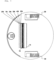
- Fig. 18 shows a multi-channel nozzle in partial section
- Fig. 19 shows an exploded view of a centrifugal regulator with a side channel.
- the present invention relates in particular to a robotic vacuum cleaner comprising a partially encapsulated rotary brush 1 driven by an electric motor 8 , which is controlled by a control unit in relation to the power input of the electric motor 8 driving a centrifugal fan 7, a vacuum section 2 of air ducts connected to the housing 3 of the rotary brush 1 at one end, and which is connected at the other end via an elastic coupling 22 to the housing of the dirt collection container 4 , which is connected via an air filter _5 to an inlet air duct 6 of a centrifugal fan 7 provided with an impeller 46 with blades that are slightly bent backwards and driven by the electric motor 8 .
- the centrifugal fan 7 is encapsulated in a spiral housing 24 with an inlet duct 49 and a side duct 47 with an air outlet 9, and connected to a multi-channel airflow straightener 10 of the air flow, the number of its channels corresponding to the number of outlets to which the same number of air ducts 11 with a small hydraulic dimension is connected at one end, which are on the side of the centrifugal fan 7 connected to the multichannel straightener 10 by a glued joint and at the other end they are mounted in the same number by conical shoulder into recesses in the upper part 12a and lower part 12b in the circular part of air ducts of the air ducts of the flat multichannel nozzle 12, By means of shaping of air ducts a connection to the same number of flat apertures which form the flat multi-channel nozzle 12 is thereby created.
- the bar 40 with the holes which serve to pass the air ducts 11 serves as a cap to connect the upper part 12a and the lower part 12b of the flat multichannel nozzle 12 .
- one straight flat supply duct or at least one side supply duct with a larger cross-section can be used to connect the spiral housing 24 and the flat nozzle, wherein this technical solution provides also significantly higher outlet air velocity than the speed of the intake vacuum air.
- the spiral housing 24 of the centrifugal fan 2 can be replaced by a side channel 47 or a pair of side channels, which are generally arranged below the impeller blade of the centrifugal fan 7. This saves the space of the entire device and, given the dimensions of the centrifugal fan 7, higher static outlet air pressures are achieved.
- the flat multi-channel nozzle 12 which is shown in Fig. 17 and Fig. 18 , is formed by an upper part 12a , which is detachably connected by a rod 45 to the housing 3 of the rotary brush 1 and a lower part 12b, which are closed at the side by side plates 41 and connected by connecting elements 42, and is connected to one side of the convex transfer surface 13, which at the other end intersects the inner surface of the housing 3 of the rotary brush 1 driven by the drive motor 23 and thus forms a raised trailing edge 25 of the convex transfer surface 13.
- the apron 26 with side plates 41 is arranged below the flat multi-channel nozzle 12.
- the whole assembly is suspended on pivoting arms 27, which are hinged by means of pins 28 to holes in the lugs 29 on the body of the robotic vacuum cleaner.
- the principle of the air recirculation in a robotic vacuum cleaner consists in maintaining a constant flow and total pressure in the entire system, but with changing flow velocities and with analogously changing static and dynamic pressures within the flow.
- the air ducts are divided into a vacuum low-speed subsystem, which comprises a housing 3 of a rotary brush 1 with the rotary brush 1 itself driven by an electric drive motor 23 , and a high-pressure overpressure subsystem comprising a system of air ducts 11 having a small hydraulic size.
- the overpressure high-speed subsystem feeds the high-velocity flow into the flat multi-channel nozzle 12 formed by a series of flat outlets, where the flow is further accelerated by reducing the outlet cross-section. Furthermore, the flow is fed along the surface of the convex transfer surface 13 close to the cleaned floor surface 14. After reaching the transfer line 15, where the high-velocity overpressure flow 17 is closest to the surface of the floor 14, the high-velocity overpressure flow layer 17 has a greater thickness than at the mouth of the outlet openings of the flat multichannel nozzle 12. The increase in air layer thickness as the convex surface 36 is flowed-around, is caused in an undesirable manner by sucking 18 into the lower static pressure region that accompanies the high velocity overpressure flow 12.
- the rate of increase in air layer thickness is directly proportional to the length of the trajectory that the flowing air must travel along the surface of the convex transfer surface 13 from the flat multichannel nozzle orifice to the transfer line 15 because the flowing layer is exposed to ambient air along the entire length of the trajectory.
- an apron 26 with side plates 41 is designed, wherein the side plates 41 limit the penetration of ambient air to the surface of the convex transfer surface 13, and thus limit the degree of undesired suction 18 and thus also the increase in the thickness of the air layer.
- the high velocity overpressure flow 17 changes the flowed-around surface from the convex transfer surface 13 to the floor surface 14, because said floor surface 14 forms in the transfer line 15 a tangent surface of the convex transfer surface 13.
- the sign of the differential of the static pressures acting on the high-velocity flow layer changes in the transfer line 15.
- Said static pressure differential arises from the fact that on the solid surface side an overpressure from the free atmosphere side acts on the flowing air layer characterized by a higher dynamic and lower static pressure, which presses the flowing layer against the solid surface.
- the high-velocity overpressure flow 17 entraining dirt particles, flows around the cleaned floor surface 14 against the blades 16 of the rotary brush 1 , which rotates with the circumferential velocity vector opposite at a lower dead centre than the high velocity overpressure flow vector 17, wherein its speed at a given cross section corresponds to a circumferential velocity of 5 - 10% of the velocity of the high-velocity overpressure flow 12.
- the dirt particles together with any large objects 21 which have been picked up by the blades 16 of the rotary brush 1 find themselves together with the counter-moving particles entrained by the high velocity overpressure flow 17 in strongly turbulent flow upon contact of the high-speed overpressure flow 17 with the blades 16 of the rotary brush 1 and are carried by the rotary brush 1 between adjacent pairs of blades 16 of the rotary brush 1 into the vacuum section 2 of the air duct and carried by slow flowing air into the dirt collection container 4, where they are stopped by an air filter 5.
- a pair of adjacent blades 16 of the rotary brush 1 and the inner wall of the housing 3 of the rotary brush 1 during its rotation form a temporary closure of the chamber 31 at the moment of passing through the housing 3, where due to a strong turbulence and vortex formation dissipation of the kinetic energy and increase of its static pressure take place, so that at the entry of the slowed down turbulent air 39 into the space of the vacuum section 2 of the air duct the flow has comparable velocity and pressure parameters as are naturally developed in the vacuum section 2 of the air duct by the centrifugal fan 7 .
- connection between the operation of the overpressure and low-pressure air subsystem means that the two air subsystems are not only structurally but also functionally connected by a partially encapsulated rotary brush 1 , thus representing the first aspect of synergistic interaction of the high velocity overpressure flow 17 and the rotary brush 1 itself.
- the ratio between the flow velocity at the mouth of the flat multichannel nozzle 12 and the velocity in the vacuum section 2 of the air duct is 16: 1, more precisely, the flow velocity in the vacuum section 2 of the air duct is 5 m / s and at the mouth of the flat multichannel nozzle 12 80 m / s.
- the low flow rate in the vacuum section 2 of the air duct is dictated by the need for sufficient permeability of the vacuum section 2 of the air duct, because all dirt particles including large objects 21 passing under the robot body must have enough space to pass safely through the vacuum section 2 of the air duct to the collecting container 4 which is housed in a shaft with a wall 32.
- no such restriction exists in the case of an overpressure air duct 11 no such restriction exists in the case of an overpressure air duct 11 or the sum of the cross-sections of the individual overpressure air ducts and their outlet in the flat multichannel nozzle 12 can be reduced in comparison with the cross-section of the vacuum section 2 of the air duct.
- the sum of the cross-sections of the outlets of the overpressure air ducts 11 is about 5% of the cross-section of the vacuum section 2 of the air duct.
- the angle of the mouth of the flat nozzle or the multichannel nozzle 12, which it encloses with the floor surface 14, is also important.
- the increase in this angle is associated with an extension of the trajectory that the air must travel between the mouth of the multichannel nozzle 12 and the transfer line 15.
- the air velocity decreases due to the turbulence 35 and the volume of the air sucked in and the thickness of the air layer in the transfer line 15 increase due to the undesired suction 18.
- the upper limit of the angle is limited by the condition that the separation indicated by the separation line 37 does not take place before the air reaches the raised trailing edge 25. This is related to the ratio of the thickness of the flowing air layer to the radius of the convex transfer surface 13. The lower is this ratio, the sooner the air separates from the convex transfer surface 13, and the lower is the upper limit of the angle of the mouth of the flat nozzle or the multi-channel nozzle which it forms with the floor surface 14.
- the lower limit of this angle is limited by two factors.
- the individual air streams need to be combined into one stream at the level of the transfer line 15. This depends on the length of the trajectory, the size of the gaps between the outlets of the individual channels and the shaping of the ends of the individual channels, which may be designed to be tapering or widening.
- the smallest angle is given by the fact that the nozzle body and the adjoining apron 26 do not represent an obstacle for the robotic vacuum cleaner, for example when crossing unevenness or sills.
- the rotary brush 1 with blades 16 in this preferred embodiment of the present invention serves as a flow rate moderator between the high - speed flow from the overpressure subsystem providing a sufficient cleaning effect and the low-speed vacuum subsystem with a large cross-section, enabling the transport of even large particles of dirt to the collecting container 4 .
- the transfer line 15, on which the high-velocity overpressure flow around the convex transfer surface 13 is closest to the floor surface 14 and changes the flowed-around surface from the convex transfer surface 13 to the floor surface 14, must be as close as possible to the rotary brush 1 with blades 16, so that the highest possible number of dirt particles released from the floor surface 14 by the high-speed overpressure flow are conveyed due to the inertial force up to the blades 16 of the rotary brush 1 .
- high-density particles when released from the surface, move along a trajectory similar to a ballistic curve, because the flow velocity that set them in motion decreases rapidly, although it still far exceeds the velocity of these particles.
- the clearance height of the convex transfer surface 13 is most +often in the range of 1 to 8 millimetres and also depends on the vertical dimension of the flat nozzle, because in the case of a thin layer of air washing the convex transfer surface 13 which would be too far from the floor 14, the air flow would not be transferred from the convex transfer surface 13 to the floor 14, the air would flow up to the raised trailing edge 25 and the system would not work.
- the flow rate be as high as possible so that the particles mechanically released by the blades 16 of the rotary brush 1 are deflected upwards into the space of the housing _3 of the rotary brush 1 by the flow-induced aerodynamic force. In this way, the penetration of said particles through the slit 20 below the transfer line 15 is prevented.
- the velocity of the high velocity overpressure flow 17 is much higher at the point when it reaches the blade 16 than the velocity of most particles released and agitated by this flow, and at the same time many times exceeds the flow rate in the vacuum section 2 of the air duct.
- the high-speed overpressure flow 17 In order to prevent backflow from the vacuum section 2 of the air duct, which would occur due to a large flow velocity differential, the high-speed overpressure flow 17 must be decelerated in a controlled manner, resulting in decelerated turbulent air 39 having a velocity equal to or close to the flow velocity in the vacuum section 2 of the air duct.
- this object is achieved by using the blades 16 of the rotary brush 1 as described above.
- An important characteristic for the function of the robotic vacuum cleaner according to the present invention is the ratio of the sum of the cross-sections of the outlet of the overpressure air ducts 11 of the high-speed part of the air duct, which is 3 to 40% of the cross-section of the vacuum section 2 of the air duct.
- the upper limit of this range is possible when using low-pressure centrifugal fans.
- the robotic vacuum cleaner works on floors autonomously, it must be able to overcome vertical obstacles such as carpets, skirting boards and thresholds.
- its cleaning elements which are primarily the rotating brush 1 and the flat multi-channel nozzle assembly 12 with the convex transfer surface 13, change their position relative to the floor surface 14.
- the high-speed overpressure flow 17 from the multichannel nozzle 12 flowing around the convex transfer surface 13 does not change the flowing surface to the floor surface 14 but flows around the convex transfer surface 13 up to the raised trailing edge 25, which directs the flow directly into the housing 3 of the rotary brush 1 . This prevents air from escaping into the atmosphere and swirling dirt on the floor surface 14.
- the apron 26 with side plates limits the unwanted suction 18 of air which is sucked from the ambient atmosphere into the reduced pressure region caused by the high velocity flow from the flat multi-channel nozzle 12 and by the flow-around the convex transfer surface 13.
- the apron 26 with the side plates 41 encloses the space behind the convex transfer surface 13 and is characterized by a smaller clearance height than corresponds to the distance of the transfer line 15 from the floor surface 14.
- the compensation for the increase in air volume due to its desired suction 19 and unwanted suction 18 takes place in a controlled manner by escaping pulsating air 38 through a periodically generated by the pulsating gap 44 under the blades 16 of the rotary brush 1 so that the flow velocity under the rotary brush 1 decreases to 0 m / s still under the body of the robotic vacuum cleaner. Due to the fact that even within this flow the static pressure is lower than in the surrounding atmosphere and the flow stops under the robotic vacuum cleaner, there can occur no leakage of impurities into the surrounding atmosphere.
- the first of them is related to the usability of the rotary brush 1 , more precisely to its circumferential speed.
- the higher is the circumferential speed of the rotary brush 1 the higher the effect on the dirt and the cleaning effect have the blades 16. More specifically, a positive effect has the higher number of interactions between the blades 16 and the floor surface 14 per unit time, because increases the probability of dirt intervention and the intensity of dirt release from carpet fibres.
- the mechanical apron is replaced by the pneumatic effect of a counter-rotating high-speed overpressure flow 17, which completely seals the space between the transfer line 15 and the floor surface 14. Thanks to the described sealing means, it is thus possible to significantly increase the rotation speed of the rotary brush 1 in comparison with the prior art.
- the second synergistic effect relates to the effect of the blades 16 on the particles trapped between the carpet fibres.
- the blades 16 strike dirt particles on the surface, in particular on the surface of the carpet, at a frequency which, at normal speeds of 1000 rpm and about 17 revolutions per second, corresponds to a frequency of about 100 strokes per second in a conventional paddle brush.
- the fibres of the carpets with the trapped dirt particles are hit and bent, causing them to be mechanically released and a considerable part is moved closer to the surface or jumps to the surface.
- These particles are then cleaned either directly or secondarily by the high-speed overpressure flow 17 on the basis of the previously described mechanisms.
- This suspension compensates for changes in the ground clearance of the robotic vacuum cleaner that occur due to the different hardness of the surfaces on which the robotic vacuum cleaner works, such as a wooden floor or a soft carpet.
- the usual density of a robotic vacuum cleaner the usual difference is 3 - 4 mm.
- the position of the self-levelling structure on a hard surface is shown in Fig. 2 .
- the relative vertical position of the drive wheels 33 and the auxiliary wheel 34 with respect to the self-levelling structure, in particular with respect to the vertical position of the blades 16, more precisely to the vertical position of the axis of the rotary brush 1 where the blades 16 of the rotary brush 1 move closely slidably against the floor surface 14 is clearly defined, and the apron 26 with the side plates has a clearance height of about 1 mm above the floor surface 14.
- Fig. 3 shows the position of said structure on a soft surface, where the drive wheels 33 and the auxiliary wheel 34 are immersed in the soft surface of the floor 14, and therefore the ground clearance of the robotic vacuum cleaner is reduced.
- the self-levelling structure which is suspended on the swing arms 27, slides into the body of the robotic vacuum cleaner and rests on the sliding surface of the apron 26 and the rotating blades 16 of the rotary brush 1 , which are immersed about 1 mm below the carpet surface.
- the present invention can be used in particular for robotic vacuum cleaners, which aim to supply fast-flowing air from the spiral housing of a centrifugal fan of a robotic vacuum cleaner directly to the floor surface.
Landscapes
- Engineering & Computer Science (AREA)
- Mechanical Engineering (AREA)
- Nozzles For Electric Vacuum Cleaners (AREA)
Description
- The invention relates to a cleaning device, in particular for a robotic vacuum cleaner, which ensures the supply of fast-flowing air from a spiral housing of a centrifugal fan of a robotic vacuum cleaner directly to the floor surface.
- In the category of robotic vacuum cleaners, a development is currently underway, which largely follows trends in other categories of home appliances and focuses primarily on data sharing and the use of elements of a so-called artificial intelligence.
- Above all, these are increasingly financially and energy-intensive navigation systems and applications for smartphones designed to control and monitor the work of the robot remotely. Some of these solutions, such as a rotary laser range finder and a computer that calculates the current position of the robotic vacuum cleaner based on measured changes in distance from objects in the cleaned space, consume about the same amount of energy as all other activities combined, in particular drive wheel drive, fan drive and of all brushes.
- The interior of the robotic vacuum cleaner is fundamentally dictated by its external dimensions, which must allow cleaning in restricted conditions, for example between the legs of chairs and under furniture.
- The restricted internal space limits the dimensions of the components that must fit in a robotic vacuum cleaner, and, in addition, most components must be in a location designated by functional reasons, and even the battery must be in a location acceptable for balancing the robot. In addition, the collection container for cleaned dirt must also have a certain minimum volume.
- It follows that the parameters of the elements that participate in the cleaning activities themselves are very limited and cannot compete comparisons with the parameters and energy sources of normal vacuum cleaners. For example, with a normal, mains-connected vacuum cleaner, the normal power input is 1.000 W and the static negative pressure generated is about 20.000 Pa. With a robotic vacuum cleaner, the power consumption of the fan corresponds to about 6 - 20 W and generates about 500 - 2.000 Pa.
- An important requirement for optimal vacuuming is to induce a rapid flow of air between the edges of the suction nozzle and the floor surface. It is desirable that the joint through which the air flows is as narrow as possible and the flow rate as high as possible. It is clear that in addition to the size of the joint, the key parameter is precisely the negative static pressure at a certain flow rate, which is able to develop a vacuum cleaner fan, and therefore centrifugal fans equipped with a diffuser are used for this purpose to achieve a cleaning effect, together with the minimal possible joint size. This is not only an obvious relationship between the joint cross-section and the flow rate, assuming a corresponding negative static pressure and flow, but an important assumption is the need to reduce the thickness of the boundary layer at the floor surface. However, achieving a sufficiently narrow joint is difficult with robotic vacuum cleaners.
- Related to this is the fact that there is a huge range of impurity dimensions, all of which must be removed from the surface and transferred to a collection container. This is not just dust, which typically has a size in the order of micrometers, but also organic and inorganic particles or objects with dimensions in the order of tens of millimetres, with different densities and aspect ratios. Leaves, crumbs, stones, hair, hairs and so-called dust tufts, which are large formations of low density that bear also electrostatic charges.
- These basic requirements for robotic vacuum cleaners are currently being addressed by several technical approaches.
- In the first of these technical approaches, the robotic vacuum cleaner uses a pair of counter-rotating rotary feed brushes with a separate suction nozzle. A pair of counter-rotating brushes mechanically removes coarse dirt from the floor surface and uses the kinetic energy mechanically imparted to the dirt to transfer it to the collection container.
- Behind the pair of brushes is designed a narrow suction nozzle formed by a pair of elastic elements, which reaches just above the cleaned surface, and the sucked fine dirt is pneumatically discharged into a separate sealed collection container.
- This design admittedly reflects the diversity of types of impurities, but not completely. It does not solve objects with a large cross-section and low density, such as typically dust tufts. These occur in large volumes in the corners of the room and under the furniture, are clearly visible and must be removed. However, in the case of the described construction, a problem arises because mechanical brushes cannot give them sufficient kinetic energy due to their low specific gravity and said objects do not reach the collecting container due to their low specific gravity, large cross-section and high aerodynamic drag. They usually end up on the floor again and due to their size they cannot be sucked into a narrow suction nozzle. So they are just moved on the floor in front of the nozzle and are scattered on it when they go out on the carpet.
- Another disadvantage is the high space requirements for the installation of all elements and the need for two separate collection containers and therefore the inconvenient emptying of containers and lengthy cleaning. In addition, the system is complex, the dust-free brushes swirl and the hair is intensely wound on the brushes and bearings, which must be removed from both brushes and their bearings.
- Another technical solution uses a simple suction nozzle. The biggest problem with this design is related to the specifications of robotic vacuum cleaners. Unlike the suction nozzle of a normal human-operated vacuum cleaner, the robotic vacuum cleaner must have a certain overhead clearance, typically 8 mm, in order to overcome vertical obstacles such as carpets, skirting boards and sills.
- Dirt has dimensions up to units of mm and unlike by normal vacuum cleaners, this fact must be taken into account by the suction device of robotic vacuum cleaners. When a person vacuuming the floor sees a crumb, the person simply raises the nozzle and then continues again with the nozzle resting on the surface. The robotic vacuum cleaner must clean everything that passes under the frame of the robotic vacuum cleaner, i.e. all dirt from dust in the size of microns to those 8 mm clearance. The construction of the suction nozzle and the dimensions of the air duct, through which the dirt is transported to the collection container, must correspond to this. In practice, this means that the minimum size of the suction nozzle must be 8 mm, and this also applies to the air duct.
- However, this means that with this design it is not possible to achieve a high flow rate at the floor surface due to the large cross-section of the suction nozzle necessary to maintain permeability for large impurities and the limited volume of air flow that the fan is able to supply due to low power input and dimensions. In addition, the nozzles are compressed exactly on the opposite side than would be required, i.e. at the mouth of the front part of the nozzle at the bottom of the frame of the robotic vacuum cleaner. At a floor surface, a flow velocity of only 4 - 5 m / s is typically achieved.
- The suction nozzle must be open from the front side to allow large impurities to pass through and so, paradoxically, although their volume share in the total volume of impurities is only in the order of percent, the need to clean them makes it impossible to create a narrow joint and thus achieve high flow rates, necessary to remove fine dust particles.
- At the same time, they make up the majority of impurities by volume and are also far more dangerous to health than large, visible crumbs.
- The third design approach is based on a rotating brush, which is located in the vacuum section of the air duct. The rotary brush driven by the electric motor is partially encapsulated and an air duct with negative air pressure opens into the housing. Behind the brush a screen is located that extends just above the floor surface.
- Particles of sufficient density and size are hit on the floor by brush blades, transported to the brush shaft and ejected by centrifugal force into the air duct and further into the collecting container. Particles of lower density and fine dust are conveyed to the collecting container by a stream of air, which partially flows around the brush and which is sucked in at the floor.
- This technical solution has a number of disadvantages. The air flow rate on the floor is defined by the circumferential speed of the brush and only slightly exceeds it due to the residual flow between the brush blades and the brush housing. The circumferential speed of the brush in a robotic vacuum cleaner is usually 2 meters per second, with a diameter of usually 40 mm and 17 revolutions per second. In the case of a mechanical tool, this speed is sufficient to remove larger impurities, but in the case of air flow it is completely insufficient to separate the impurities from the surface. The air flow in this construction does not serve as one of the primary tools for cleaning the surface, but only as an auxiliary means for the removal and transport of fine dust blown by the brush into the collection container.
- This design also suffers from winding the hair around the brush because the surrounding flow is too slow.
- A fourth possibility of the prior art is a solution which is based on a pair of profiled counter-rotating elastic cylinders located in a vacuum air duct, which at the same time forms a suction nozzle.
- This solution has the following technical disadvantages. The air duct is characterized by sudden changes in cross-section, which causes turbulent flow around the profiled cylinders and problematic sealing of the profiled rotating cylinders. When cleaning carpets, the clearance height of the robotic vacuum cleaner changes due to the high surface load of the drive wheels and thus the geometry of the suction device with respect to the floor changes. The roller profiles sit completely down on the carpet surface and there is a further increase in turbulent flow in the remaining holes between the rollers and the floor. The flow velocity in the remaining holes at the floor was measured at 2 m / s.
- Due to the design of the device with small tolerances between the rollers and the shafts, tangled hair is a big problem, which also clogs the channels between the floor and the rollers and blocks the flow of air.
- The closest prior art is disclosed, for example, in the patent documents
US 2003/132152 A1 ,US 2019/090704 A1 andEP 0 564 222 A1 - The invention is based on a design which aims to supply fast-flowing air from a spiral housing or at least one side duct of a centrifugal fan directly to the floor surface, the essence of which consists in that a convex transfer surface is arranged between the flat nozzle and the rotary brush.
- The flat nozzle is formed as a multichannel nozzle between the convex transfer surface and the apron with an inclination of the multichannel nozzle orifice in the range of 20 to 60 degrees from the horizontal plane, the clearance height between the convex transfer surface and the floor being in the range of 1 to 8 millimetres.
- The convex transfer surface behind the mouth of the flat nozzle continues with a rounded approach and ends with a raised trailing edge, which is part of the rotating brush housing.
- The flat nozzle is continuously connected to the spiral housing of the centrifugal fan or at least one side duct by means of a multi-channel air flow straightener, the number of ducts of which connects to a system of individual air ducts that terminate at the inlet to the multi-channel nozzle.
- The cross section of the multichannel nozzle decreases in the range between the mouth of the system of individual air ducts in the multichannel nozzle and the mouth of the multichannel nozzle.
- The apron is rounded toward the floor from the multi-channel nozzle moth with a maximum clearance height in the range of 0.5 to 2 millimetres and is less than the clearance height of the convex transfer surface at the lowest point relative to the floor surface.
- The rotary brush is housed in a housing, which is followed by a vacuum section of the air duct, which is connected by an elastic coupling to the housing of the collecting container.
- The rotary brush is housed in the housing between the vacuum section of the air duct, which is connected by an elastic coupling to the housing of the collecting container and the overpressure high-speed part of the air duct of the robotic vacuum cleaner flowing around the floor surface.
- The sum of the cross-sections of the outlets of the overpressure air ducts of the high-speed part of the air duct is 3 to 40% of the cross-section of the vacuum section of the air duct.
- The cleaning device is suspended on parallel pivoting arms mounted on pins, which are pivotably mounted in lugs anchored to the structure of the robotic vacuum cleaner.
- A flat supply channel or at least one side supply channel is arranged between the flat nozzle and the centrifugal fan.
- By means of a set of air ducts with a small cross-section, the invention provides a sufficient flow at a given flow rate, while the sufficiently low hydraulic dimension of the individual air ducts creates the conditions for laminar flow. This minimizes energy losses and flow velocities caused by turbulent flow, the flow is evenly distributed along the entire convex transfer surface, and sharp bends in the ducts and abrupt changes in their cross-section are thus eliminated.
- The air duct assembly continuously connects the spiral housing outlet of the centrifugal fan to a corresponding small diameter air duct assembly, thereby calming the turbulent flow from the spiral housing outlet of the centrifugal fan. This ensures a smooth physical transition between the different cross-sections and shapes of the spiral housing outlet and the small diameter air ducts, as well as a smooth transition between turbulent air flow from the spiral housing outlet of the centrifugal fan and laminar flow in the small diameter ducts.
- The centrifugal fan with a spiral housing can be replaced by a centrifugal fan with at least one side channel, which is an optimal way to transform the kinetic energy of the air, which is obtained from the blades of a rotating impeller, into static energy. The efficiency of the side channel design is significantly higher in the transformation of kinetic energy into static energy than in the use of spiral housings, while minimizing the external dimensions of the centrifugal fan.
- The convex transfer surface feeds the high velocity flow layer from the flat multi-channel outlet nozzle to the floor surface. At the lowest ground clearance, the flowing high-velocity flow layer changes the flowing convex transfer surface to the floor surface because the direction of the static pressure differential that presses the high-velocity flow layer against said surfaces changes. Bringing the high-velocity air layer to the floor surface parallel to the floor surface prevents contaminated air from escaping, unlike the sloping direct air flow, because the kinetic pressure in the air layer flowing parallel to the floor means lower static pressure than the surrounding atmosphere. Therefore, air contaminated with dirt cannot escape to the surroundings.
- The prior art is also improved by using a significantly simpler nozzle and air duct design, which can be a mere slit, and also by using simpler and cheaper centrifugal fans, which are designed for lower speeds, which reduces the demand on the mounting of the centrifugal fan impeller, its cooling and balancing.
- The air flowing rapidly above the surface generates an area of lower static pressure above the surface than below it, namely, for example, between the fibres of the carpet. This creates the desired upward suction, which releases and transports dirt particles from the space between the carpet fibres to the high-speed flow and further to the collecting container.
- Unwanted blowing of dirt from the floor surface is thus avoided if some or all of the convex transfer surface moves away from the floor, for example when crossing between different types of floor coverings, more than the thickness of the flowing layer of the high-speed air stream. At the mentioned places of the surface, the flow around the surface is completed up to the trailing edge of the convex transfer surface and the air flow is discharged into the space of the rotary brush, slowed down and discharged into the collecting container.
- The convex shape of the transfer surface ensures smooth overcoming of protruding surfaces, such as carpet edges or door sills, and therefore the convex transfer surface can be placed just above the floor and high-velocity flow in a thin layer just above the surface, which is energy efficient.
- The working distance between the lowest point of the convex transfer surface and the floor surface is in direct proportion to the vertical dimension of the flat multi-channel nozzle from which the high velocity air jet layer is discharged to the convex transfer surface and the trajectory through which where the current changes the flowed area. When the robotic vacuum cleaner moves on the floor in a standard horizontal position, the joint between the convex transfer surface and the floor surface maintains its defined size, which guarantees the desired change in surface flow.
- When the convex transfer surface moves away from the floor surface further than corresponds to the thickness of the flowing layer of the high velocity air stream, the flow of the convex transfer surface is completed only at the trailing edge of the convex transfer surface, defined by the intersection of the convex transfer surface and the inner surface of the rotary brush case and the air stream is discharged into the space of the rotating brush, slowed down and taken to a collecting container.
- This redirects the air flow from the floor surface and prevents blowing of dirt from the floor surface and uncontrolled leakage of contaminated air into the atmosphere.
- An important aspect is the relationship between the circumferential speed of the rotary brush and the flow rate flowing around the convex transfer surface, which is provided by the control unit. The aim is to maintain a dynamic balance in terms of the mechanical effect of the rotary brush on the dirt particles and the opposite aerodynamic effect of high velocity flow and to maintain a dynamic balance between the volume and velocity of air escaping under the rotary brush and the velocity of particles accelerated by the rotary brush towards the joint. More precisely, the velocity of the air escaping under the brush must slow down to zero even below the body of the robotic vacuum cleaner and no particles must penetrate below the convex transfer surface against the air flow.
- The rotary brush acts as a flow rate equalizer in the overpressure and low-pressure branches of the air ducts. The high-velocity flow from the convex transfer surface moves the particles from the floor surface and subsequently this air, saturated with dirt particles, is forcibly decelerated in temporarily formed chambers between the rotary blade blades to the speed in the suction low-pressure branch to avoid problems with the air flow velocity differential in both branches of the air ducts.
- The apron with side plates enclosing the space behind the flat multichannel nozzle with a convex transfer surface with a distance from the floor surface less than the distance of the convex transfer surface from the floor surface limits the amount of air that can be sucked from the ambient atmosphere into the reduced pressure area due to high velocity flow from flat nozzles and bypassing the cylindrical convex transfer surface.
- At the same time, reducing the intake air content reduces the problem of maintaining a constant volume of air and reduces the deceleration and growth of the air layer that flows around the cylindrical convex transfer surface, which results in increased floor surface cleaning efficiency.
- At the same time, the apron is designed as an aid to ensure a minimum distance between the lower surface edge of the convex transfer surface and the floor surface, thus ensuring the proper function of the air flow below the convex transfer surface.
- The entire cleaning device, including the convex transfer surface, the flat multi-channel nozzle, the apron with side plates reducing air intake, the rotary brush with the motor and gearbox, the rotary brush chamber with the vacuum air duct, is connected to the collecting container housing by an elastic transition element and suspended on parallel pivoted arms mounted on the pins on the frame of the robotic vacuum cleaner. This solution compensates changes in the ground clearance of the robotic vacuum cleaner that occur due to the different hardness of the surfaces on which the robotic vacuum cleaner works, i.e. on a wooden floor or a soft carpet. With the usual weight of a robotic vacuum cleaner, the usual difference in ground clearance is up to 3 - 4 mm.
- Maintaining a constant preset clearance height at the lowest edge of the convex transfer surface above the floor surface is important to ensure proper airflow transfer function from the convex transfer surface to the floor surface. This prevents excessive friction and unwanted bending of the rotary brush blades, thus protecting the motor and saving energy, protecting the carpet from excessive wear due to the rotary brush and assisting navigation systems by not introducing unnecessary accelerations that have to be evaluated by robotic vacuum cleaner navigation systems.
- A centrifugal high-speed fan with backward curved blades, a semi-closed impeller and a spiral housing produces a high static pressure air flow even at the cost of a lower flow rate. One of the basic ideas of the present invention is a differentiated approach to removing different categories of surface impurities. The primary role of the air flow is to remove fine dust particles for which the high-velocity flow is best suited. If the typical size of these particles, which is measured in micrometers, is taken into account, the decisive factor is not the power of the flow rate or the thickness of the layer of air flowing over the surface to be cleaned. Therefore, a thin layer in the range of 1 - 2 mm is completely sufficient to remove said particles from the surface and from the space between the carpet fibres.
- An exemplary embodiment of the invention is shown in the accompanying drawings, in which
Fig. 1 shows a partial section of a robotic vacuum cleaner in axonometric view showing the location of key features of the invention,Fig. 2 shows a partial section of a robotic vacuum cleaner showing the position of a cleaning deviceFig. 3 shows a partial section of a robotic vacuum cleaner indicating the position of the cleaning device when the robotic vacuum cleaner is driving on a soft surface,Fig. 4 shows a detailed section of a robotic vacuum cleaner cleaning device with a rotary brush, a rotary brush housing, a flat multi-channel nozzle, an apron with side plates and a vertically movable hinge,Fig. 5 shows a detailed section of the cleaning device indicating the air flow under the rotary brush blades,Fig. 6 shows schematically the dependence of the change in flow speed on time and the size of the slit under the rotary brush blades,Fig. 7 shows a bottom view of the robotic vacuum cleaner body with indication of the course of the flow velocity under the blades of the rotary brush,Fig. 8 shows a front view of the robotic vacuum cleaner in a horizontal, working position,Fig. 9 shows a side view of the robotic vacuum cleaner in a horizontal, working position,Fig. 10 shows a detailed section of the cleaning device indicating the air flow at a horizontal, working position,Fig. 11 shows a front view of the robotic vacuum cleaner in an inclined, crossing position,Fig. 12 shows a side view of the robotic vacuum cleaner in an inclined, crossing position,Fig. 13 shows a detailed section of the cleaning device indicating the air flow in the inclined, crossing position of the vacuum cleaner.Fig. 14 shows a detailed embodiment of a robotic vacuum cleaner cleaning device when working on a carpet at a stage where dirt comes into contact with the rotary brush,Fig. 15 shows a detailed embodiment of a robotic vacuum cleaner cleaning device when working on a carpet at a stage where dirt is carried in the space between rotary brush blades and rotary brush housing,Fig. 16 shows a detailed embodiment of a robotic vacuum cleaner cleaning device when working on a carpet at a stage when dirt is expelled by the rotary brush blades from the space between the blades into the vacuum section,Fig. 17 shows schematically a robotic vacuum cleaner cleaning device between the air duct and rotary brush in an exploded view,Fig. 18 shows a multi-channel nozzle in partial section, andFig. 19 shows an exploded view of a centrifugal regulator with a side channel. - The present invention relates in particular to a robotic vacuum cleaner comprising a partially encapsulated
rotary brush 1 driven by anelectric motor 8, which is controlled by a control unit in relation to the power input of theelectric motor 8 driving acentrifugal fan 7, avacuum section 2 of air ducts connected to thehousing 3 of therotary brush 1 at one end, and which is connected at the other end via anelastic coupling 22 to the housing of thedirt collection container 4, which is connected via an air filter _5 to aninlet air duct 6 of acentrifugal fan 7 provided with animpeller 46 with blades that are slightly bent backwards and driven by theelectric motor 8. Thecentrifugal fan 7 is encapsulated in aspiral housing 24 with aninlet duct 49 and aside duct 47 with an air outlet 9, and connected to amulti-channel airflow straightener 10 of the air flow, the number of its channels corresponding to the number of outlets to which the same number ofair ducts 11 with a small hydraulic dimension is connected at one end, which are on the side of thecentrifugal fan 7 connected to themultichannel straightener 10 by a glued joint and at the other end they are mounted in the same number by conical shoulder into recesses in theupper part 12a andlower part 12b in the circular part of air ducts of the air ducts of the flatmultichannel nozzle 12, By means of shaping of air ducts a connection to the same number of flat apertures which form the flatmulti-channel nozzle 12 is thereby created. Thebar 40 with the holes which serve to pass theair ducts 11 serves as a cap to connect theupper part 12a and thelower part 12b of the flatmultichannel nozzle 12. - Alternatively, instead of a
multi-channel straightener 10 with a large number ofair ducts 11, one straight flat supply duct or at least one side supply duct with a larger cross-section can be used to connect thespiral housing 24 and the flat nozzle, wherein this technical solution provides also significantly higher outlet air velocity than the speed of the intake vacuum air. - The
spiral housing 24 of thecentrifugal fan 2 can be replaced by aside channel 47 or a pair of side channels, which are generally arranged below the impeller blade of thecentrifugal fan 7. This saves the space of the entire device and, given the dimensions of thecentrifugal fan 7, higher static outlet air pressures are achieved. - The flat
multi-channel nozzle 12, which is shown inFig. 17 andFig. 18 , is formed by anupper part 12a, which is detachably connected by arod 45 to thehousing 3 of therotary brush 1 and alower part 12b, which are closed at the side byside plates 41 and connected by connectingelements 42, and is connected to one side of theconvex transfer surface 13, which at the other end intersects the inner surface of thehousing 3 of therotary brush 1 driven by thedrive motor 23 and thus forms a raised trailingedge 25 of theconvex transfer surface 13. - The
apron 26 withside plates 41 is arranged below the flatmulti-channel nozzle 12. The whole assembly is suspended on pivotingarms 27, which are hinged by means ofpins 28 to holes in thelugs 29 on the body of the robotic vacuum cleaner. - The principle of the air recirculation in a robotic vacuum cleaner consists in maintaining a constant flow and total pressure in the entire system, but with changing flow velocities and with analogously changing static and dynamic pressures within the flow. The air ducts are divided into a vacuum low-speed subsystem, which comprises a
housing 3 of arotary brush 1 with therotary brush 1 itself driven by anelectric drive motor 23, and a high-pressure overpressure subsystem comprising a system ofair ducts 11 having a small hydraulic size. - The overpressure high-speed subsystem feeds the high-velocity flow into the flat
multi-channel nozzle 12 formed by a series of flat outlets, where the flow is further accelerated by reducing the outlet cross-section. Furthermore, the flow is fed along the surface of theconvex transfer surface 13 close to the cleanedfloor surface 14. After reaching thetransfer line 15, where the high-velocity overpressure flow 17 is closest to the surface of thefloor 14, the high-velocityoverpressure flow layer 17 has a greater thickness than at the mouth of the outlet openings of the flatmultichannel nozzle 12. The increase in air layer thickness as theconvex surface 36 is flowed-around, is caused in an undesirable manner by sucking 18 into the lower static pressure region that accompanies the highvelocity overpressure flow 12. The rate of increase in air layer thickness is directly proportional to the length of the trajectory that the flowing air must travel along the surface of theconvex transfer surface 13 from the flat multichannel nozzle orifice to thetransfer line 15 because the flowing layer is exposed to ambient air along the entire length of the trajectory. To limit such growth, anapron 26 withside plates 41 is designed, wherein theside plates 41 limit the penetration of ambient air to the surface of theconvex transfer surface 13, and thus limit the degree ofundesired suction 18 and thus also the increase in the thickness of the air layer. - Upon reaching the
transfer line 15, the highvelocity overpressure flow 17 changes the flowed-around surface from theconvex transfer surface 13 to thefloor surface 14, because saidfloor surface 14 forms in the transfer line 15 a tangent surface of theconvex transfer surface 13. At the same time, the sign of the differential of the static pressures acting on the high-velocity flow layer changes in thetransfer line 15. - Said static pressure differential arises from the fact that on the solid surface side an overpressure from the free atmosphere side acts on the flowing air layer characterized by a higher dynamic and lower static pressure, which presses the flowing layer against the solid surface.
- The high-
velocity overpressure flow 17, entraining dirt particles, flows around the cleanedfloor surface 14 against theblades 16 of therotary brush 1, which rotates with the circumferential velocity vector opposite at a lower dead centre than the high velocityoverpressure flow vector 17, wherein its speed at a given cross section corresponds to a circumferential velocity of 5 - 10% of the velocity of the high-velocity overpressure flow 12. The dirt particles together with anylarge objects 21 which have been picked up by theblades 16 of therotary brush 1 find themselves together with the counter-moving particles entrained by the highvelocity overpressure flow 17 in strongly turbulent flow upon contact of the high-speed overpressure flow 17 with theblades 16 of therotary brush 1 and are carried by therotary brush 1 between adjacent pairs ofblades 16 of therotary brush 1 into thevacuum section 2 of the air duct and carried by slow flowing air into thedirt collection container 4, where they are stopped by anair filter 5. - A pair of
adjacent blades 16 of therotary brush 1 and the inner wall of thehousing 3 of therotary brush 1 during its rotation form a temporary closure of thechamber 31 at the moment of passing through thehousing 3, where due to a strong turbulence and vortex formation dissipation of the kinetic energy and increase of its static pressure take place, so that at the entry of the slowed downturbulent air 39 into the space of thevacuum section 2 of the air duct the flow has comparable velocity and pressure parameters as are naturally developed in thevacuum section 2 of the air duct by thecentrifugal fan 7. - The connection between the operation of the overpressure and low-pressure air subsystem means that the two air subsystems are not only structurally but also functionally connected by a partially encapsulated
rotary brush 1, thus representing the first aspect of synergistic interaction of the highvelocity overpressure flow 17 and therotary brush 1 itself. - It is precisely the location of the
rotary brush 1 with theblades 16 between thevacuum section 2 of the air duct and the high-velocity overpressure flow 17 flowing around thefloor surface 14, which allows the desired high velocity differential between the low-pressure and overpressure flow to be used. - In a preferred embodiment, the ratio between the flow velocity at the mouth of the flat
multichannel nozzle 12 and the velocity in thevacuum section 2 of the air duct is 16: 1, more precisely, the flow velocity in thevacuum section 2 of the air duct is 5 m / s and at the mouth of the flatmultichannel nozzle 12 80 m / s. - It is clear that without the forced deceleration which takes place inside the
housing 3 of therotary brush 1, the speed could not be reduced at short distances between thetransfer line 15 and thevacuum section 2 of the air duct, because in a natural way, i.e. by friction between the high velocity flow and ambient atmosphere, the speed compensation would require the distance about 500 mm. - The low flow rate in the
vacuum section 2 of the air duct is dictated by the need for sufficient permeability of thevacuum section 2 of the air duct, because all dirt particles includinglarge objects 21 passing under the robot body must have enough space to pass safely through thevacuum section 2 of the air duct to the collectingcontainer 4 which is housed in a shaft with awall 32. In contrast, in the case of anoverpressure air duct 11, no such restriction exists. For this reason, the cross-section of theoverpressure air duct 11 or the sum of the cross-sections of the individual overpressure air ducts and their outlet in the flatmultichannel nozzle 12 can be reduced in comparison with the cross-section of thevacuum section 2 of the air duct. In a preferred embodiment, the sum of the cross-sections of the outlets of theoverpressure air ducts 11 is about 5% of the cross-section of thevacuum section 2 of the air duct. The result is a desirable increase in flow rate which, despite a slight deceleration during the flow around theconvex transfer surface 13 due to friction with ambient air accompanied byturbulences 35, positively affects the cleaning effect on thefloor surface 14 because the high velocity flow generates an area of reduced static pressure above thefloor surface 14 and thus causes the desirableupward suction 19, which also releases otherwise inaccessible dirt from the space between the carpet fibres. - For the effectiveness of the cleaning effect, the angle of the mouth of the flat nozzle or the
multichannel nozzle 12, which it encloses with thefloor surface 14, is also important. The increase in this angle is associated with an extension of the trajectory that the air must travel between the mouth of themultichannel nozzle 12 and thetransfer line 15. The air velocity decreases due to theturbulence 35 and the volume of the air sucked in and the thickness of the air layer in thetransfer line 15 increase due to theundesired suction 18. - The upper limit of the angle is limited by the condition that the separation indicated by the
separation line 37 does not take place before the air reaches the raised trailingedge 25. This is related to the ratio of the thickness of the flowing air layer to the radius of theconvex transfer surface 13. The lower is this ratio, the sooner the air separates from theconvex transfer surface 13, and the lower is the upper limit of the angle of the mouth of the flat nozzle or the multi-channel nozzle which it forms with thefloor surface 14. - The lower limit of this angle is limited by two factors. In the case of a
multi-channel nozzle 12, the individual air streams need to be combined into one stream at the level of thetransfer line 15. This depends on the length of the trajectory, the size of the gaps between the outlets of the individual channels and the shaping of the ends of the individual channels, which may be designed to be tapering or widening. In the case of all flat nozzles, the smallest angle is given by the fact that the nozzle body and the adjoiningapron 26 do not represent an obstacle for the robotic vacuum cleaner, for example when crossing unevenness or sills. - Beyond the traditional technical task of the
rotary brush 1, which consists in collecting coarser dirt from thefloor surface 14, tapping the cleaned floor, especially carpets and transporting loose dirt to thevacuum section 2 of the air duct, therotary brush 1 withblades 16 in this preferred embodiment of the present invention serves as a flow rate moderator between the high - speed flow from the overpressure subsystem providing a sufficient cleaning effect and the low-speed vacuum subsystem with a large cross-section, enabling the transport of even large particles of dirt to the collectingcontainer 4. - The
transfer line 15, on which the high-velocity overpressure flow around theconvex transfer surface 13 is closest to thefloor surface 14 and changes the flowed-around surface from theconvex transfer surface 13 to thefloor surface 14, must be as close as possible to therotary brush 1 withblades 16, so that the highest possible number of dirt particles released from thefloor surface 14 by the high-speed overpressure flow are conveyed due to the inertial force up to theblades 16 of therotary brush 1. In particular, high-density particles, when released from the surface, move along a trajectory similar to a ballistic curve, because the flow velocity that set them in motion decreases rapidly, although it still far exceeds the velocity of these particles. The clearance height of theconvex transfer surface 13 is most +often in the range of 1 to 8 millimetres and also depends on the vertical dimension of the flat nozzle, because in the case of a thin layer of air washing theconvex transfer surface 13 which would be too far from thefloor 14, the air flow would not be transferred from theconvex transfer surface 13 to thefloor 14, the air would flow up to the raised trailingedge 25 and the system would not work. - At the same time, it is desirable that in the space between the
blades 16 and thetransfer line 15 the flow rate be as high as possible so that the particles mechanically released by theblades 16 of therotary brush 1 are deflected upwards into the space of the housing _3 of therotary brush 1 by the flow-induced aerodynamic force. In this way, the penetration of said particles through theslit 20 below thetransfer line 15 is prevented. - Since the
distance 43 between the lowest level of theconvex transfer surface 13 and the lowest level of therotary brush 1 must be short, the velocity of the highvelocity overpressure flow 17 is much higher at the point when it reaches theblade 16 than the velocity of most particles released and agitated by this flow, and at the same time many times exceeds the flow rate in thevacuum section 2 of the air duct. In order to prevent backflow from thevacuum section 2 of the air duct, which would occur due to a large flow velocity differential, the high-speed overpressure flow 17 must be decelerated in a controlled manner, resulting in deceleratedturbulent air 39 having a velocity equal to or close to the flow velocity in thevacuum section 2 of the air duct. In the presented preferred embodiment of the present invention, this object is achieved by using theblades 16 of therotary brush 1 as described above. - An important characteristic for the function of the robotic vacuum cleaner according to the present invention is the ratio of the sum of the cross-sections of the outlet of the
overpressure air ducts 11 of the high-speed part of the air duct, which is 3 to 40% of the cross-section of thevacuum section 2 of the air duct. The upper limit of this range is possible when using low-pressure centrifugal fans. - Because the robotic vacuum cleaner works on floors autonomously, it must be able to overcome vertical obstacles such as carpets, skirting boards and thresholds. When the robotic vacuum cleaner overcomes an obstacle, its cleaning elements, which are primarily the
rotating brush 1 and the flatmulti-channel nozzle assembly 12 with theconvex transfer surface 13, change their position relative to thefloor surface 14. - At the moment when the
rotary brush 1 and the flatmultichannel nozzle assembly 12 with theconvex transfer surface 13 are raised, as shown inFigs. 11 and 12 , in whole or in part above thefloor surface 14 so that the distance between thetransfer line 15 and thefloor 14 exceeds the thickness of the flowing air layer, the high-speed overpressure flow 17 from themultichannel nozzle 12 flowing around theconvex transfer surface 13 does not change the flowing surface to thefloor surface 14 but flows around theconvex transfer surface 13 up to the raised trailingedge 25, which directs the flow directly into thehousing 3 of therotary brush 1. This prevents air from escaping into the atmosphere and swirling dirt on thefloor surface 14. - The
apron 26 with side plates limits theunwanted suction 18 of air which is sucked from the ambient atmosphere into the reduced pressure region caused by the high velocity flow from the flatmulti-channel nozzle 12 and by the flow-around theconvex transfer surface 13. - The
apron 26 with theside plates 41 encloses the space behind theconvex transfer surface 13 and is characterized by a smaller clearance height than corresponds to the distance of thetransfer line 15 from thefloor surface 14. - The compensation for the increase in air volume due to its desired
suction 19 andunwanted suction 18 takes place in a controlled manner by escaping pulsatingair 38 through a periodically generated by the pulsating gap 44 under theblades 16 of therotary brush 1 so that the flow velocity under therotary brush 1 decreases to 0 m / s still under the body of the robotic vacuum cleaner. Due to the fact that even within this flow the static pressure is lower than in the surrounding atmosphere and the flow stops under the robotic vacuum cleaner, there can occur no leakage of impurities into the surrounding atmosphere. - There are two other aspects of the synergistic action between the
rotary brush 1 and the high-speed overpressure flow 17. - The first of them is related to the usability of the
rotary brush 1, more precisely to its circumferential speed. The higher is the circumferential speed of therotary brush 1, the higher the effect on the dirt and the cleaning effect have theblades 16. More specifically, a positive effect has the higher number of interactions between theblades 16 and the floor surface 14 per unit time, because increases the probability of dirt intervention and the intensity of dirt release from carpet fibres. - In the prior art of robotic vacuum cleaners, the speed of rotation of the rotary brush and thus its circumferential speed is limited, because the speed of vacuum flow along the brush is low for previously described reasons and behind the brush there are only a mechanical apron which must maintain a
certain ground clearance 30 above the floor surface, so as not to prevent the robot from moving and overcoming vertical obstacles. - In the present preferred embodiment, the mechanical apron is replaced by the pneumatic effect of a counter-rotating high-
speed overpressure flow 17, which completely seals the space between thetransfer line 15 and thefloor surface 14. Thanks to the described sealing means, it is thus possible to significantly increase the rotation speed of therotary brush 1 in comparison with the prior art. The higher the speed of the high-speed overpressure flow 17, the higher the rotation speed of therotary brush 1 can be used. That is, each increase in the speed of the high-speed overpressure flow 17 has a multiplier effect, because the circumferential speed of therotary brush 1 and the consequent increase in the cleaning effect is also increased. - The second synergistic effect relates to the effect of the
blades 16 on the particles trapped between the carpet fibres. Theblades 16 strike dirt particles on the surface, in particular on the surface of the carpet, at a frequency which, at normal speeds of 1000 rpm and about 17 revolutions per second, corresponds to a frequency of about 100 strokes per second in a conventional paddle brush. At this frequency, the fibres of the carpets with the trapped dirt particles are hit and bent, causing them to be mechanically released and a considerable part is moved closer to the surface or jumps to the surface. These particles are then cleaned either directly or secondarily by the high-speed overpressure flow 17 on the basis of the previously described mechanisms. - The flat
multi-channel nozzle 12, theapron 26 withside plates 41 reducing the air intake, theconvex transfer surface 13, therotary brush 1 with theelectric motor 8 and gearbox, thehousing 3 of therotary brush 1 with itsvacuum section 2 of the air duct, which is by anelastic coupling 22 connected to thewall 32 of the housings of the collectingcontainer 4, are suspended as a whole on parallel pivotedarms 27 suspended onpins 28 onlugs 29 of the robotic vacuum cleaner structure. - This suspension compensates for changes in the ground clearance of the robotic vacuum cleaner that occur due to the different hardness of the surfaces on which the robotic vacuum cleaner works, such as a wooden floor or a soft carpet. With the usual density of a robotic vacuum cleaner, the usual difference is 3 - 4 mm.
- The position of the self-levelling structure on a hard surface is shown in
Fig. 2 . On the hard surface, the relative vertical position of thedrive wheels 33 and theauxiliary wheel 34 with respect to the self-levelling structure, in particular with respect to the vertical position of theblades 16, more precisely to the vertical position of the axis of therotary brush 1 where theblades 16 of therotary brush 1 move closely slidably against thefloor surface 14 is clearly defined, and theapron 26 with the side plates has a clearance height of about 1 mm above thefloor surface 14. -
Fig. 3 shows the position of said structure on a soft surface, where thedrive wheels 33 and theauxiliary wheel 34 are immersed in the soft surface of thefloor 14, and therefore the ground clearance of the robotic vacuum cleaner is reduced. On a soft surface, the self-levelling structure, which is suspended on theswing arms 27, slides into the body of the robotic vacuum cleaner and rests on the sliding surface of theapron 26 and therotating blades 16 of therotary brush 1, which are immersed about 1 mm below the carpet surface. - The present invention can be used in particular for robotic vacuum cleaners, which aim to supply fast-flowing air from the spiral housing of a centrifugal fan of a robotic vacuum cleaner directly to the floor surface.
-
- 1
- rotary brush
- 2
- vacuum section
- 3
- housing
- 4
- collection container
- 5
- air filter
- 6
- inlet air duct
- 7
- centrifugal radial flow fan
- 8
- electric motor
- 9
- air outlet
- 10
- multichannel straightener
- 11
- air duct
- 12
- multichannel nozzle
- 12a
- upper part
- 12b
- lower part
- 13
- convex transfer area
- 14
- floor
- 15
- line
- 16
- blade
- 17
- high-speed overpressure flow
- 18
- unwanted suction
- 19
- desirable suction
- 20
- gap
- 21
- large objects
- 22
- elastic coupling
- 23
- drive motor
- 24
- spiral housing
- 25
- raised trailing edge
- 26
- apron
- 27
- pivoted arm
- 28
- pin
- 29
- lug
- 30
- approach
- 31
- chamber
- 32
- wall
- 33
- drive wheel
- 34
- auxiliary wheel
- 35
- turbulence
- 36
- circulation around a convex surface
- 37
- separation lines
- 38
- escaping pulsating air
- 39
- decelerated turbulent air
- 40
- bar
- 41
- side plate
- 42
- fasteners
- 43
- distance
- 44
- pulsating gap
- 45
- rod
- 46
- impeller
- 47
- side channel
- 49
- input channel
Claims (11)
- A cleaning device, in particular for robotic vacuum cleaners, characterized in that a convex transfer surface (13) is arranged between a flat nozzle and a rotary brush (1).
- The cleaning device, in particular for robotic vacuum cleaners according to Claim 1, characterized in that the flat nozzle is designed as a multichannel nozzle (12) between the convex transfer surface (13) and the apron (26) with an inclined orifice of the multichannel nozzle (12) from 20 to 60 degrees from the horizontal plane, wherein the clearance height between the convex transfer surface (13) and the floor (14) being in the range of 1 to 8 millimetres.
- The cleaning device, in particular for robotic vacuum cleaners according to the preceding Claims, characterized in that the convex transfer surface (13) continues behind the mouth of the flat nozzle with a rounded approach (30) and ends with a raised trailing edge (25) which is part of the housing (3) of the rotary brush (1).
- The cleaning device, in particular for robotic vacuum cleaners according to Claim 1, characterized in that the flat nozzle is continuously connected to the spiral housing (24) of the centrifugal fan (7) or at least one side channel by means of a multi-channel air flow straightener (10), whose number of channels connects to the system of individual air ducts (11), which are terminated at the inlet to the multi-channel nozzle (12).
- The cleaning device, in particular for robotic vacuum cleaners according to the preceding Claims, characterized in that the cross section of the multichannel nozzle (12) decreases in the range between the mouth of the individual air ducts (11) in the multichannel nozzle (12) and the mouth of the multichannel nozzle (12).
- The cleaning device, in particular for robotic vacuum cleaners according to Claim 2, characterized in that the apron (26) is rounded towards the floor (14) away from the mouth of the multichannel nozzle (12) with a minimum clearance height in the range from 0.5 to 2 millimetres and is smaller than the clearance height of the approach (30) of the convex transfer surface (13) at the lowest point in relation to the floor surface (14).
- The cleaning device, in particular for robotic vacuum cleaners according to Claim 1, characterized in that the rotary brush (1) is accommodated in a housing (3), which is followed by a vacuum section (2) of the air duct which is connected to the collecting container housing (4) by means of an elastic coupling (22).
- The cleaning device, in particular for robotic vacuum cleaners according to Claim 1, characterized in that the rotary brush (1) is accommodated in a housing (3) between the vacuum section (2) of the air duct which is connected by means of an elastic coupling (22) to the collecting container housing (4) and an overpressure high-speed part of the air duct of the robotic vacuum cleaner, flowing around the floor surface (14).
- The cleaning device, in particular for robotic vacuum cleaners according to Claim 8, characterized in that the sum of the cross sections of the outlets of the overpressure air ducts (11) of the high-speed section of the air duct is 3 to 40% of the cross section of the vacuum section (2) of the air duct.
- The cleaning device, in particular for robotic vacuum cleaners according to the preceding Claims, characterized in that the cleaning device is suspended on parallel pivoted arms (27) mounted on pins (28) which arerotatably mounted in lugs (29) anchored to the robotic vacuum cleaner structure.
- The cleaning device, in particular for robotic vacuum cleaners according to Claim 1, characterized in that a flat supply channel or at least one side supply channel is arranged between the flat nozzle and the centrifugal fan (7).
Priority Applications (1)
| Application Number | Priority Date | Filing Date | Title |
|---|---|---|---|
| DE21707892.2T DE21707892T1 (en) | 2020-03-09 | 2021-02-09 | CLEANING DEVICE, ESPECIALLY FOR ROBOTIC VACUUM CLEANERS |
Applications Claiming Priority (3)
| Application Number | Priority Date | Filing Date | Title |
|---|---|---|---|
| CZ2020-37313U CZ34167U1 (en) | 2020-03-09 | 2020-03-09 | Cleaning devices, especially for robotic vacuum cleaners |
| CZ2020121A CZ309156B6 (en) | 2020-03-09 | 2020-03-09 | Vacuum cleaner cleaning equipment, especially robotic |
| PCT/CZ2021/000006 WO2021180254A1 (en) | 2020-03-09 | 2021-02-09 | Cleaning device, in particular for robotic vacuum cleaners |
Publications (3)
| Publication Number | Publication Date |
|---|---|
| EP4117495A1 EP4117495A1 (en) | 2023-01-18 |
| EP4117495B1 true EP4117495B1 (en) | 2023-11-29 |
| EP4117495C0 EP4117495C0 (en) | 2023-11-29 |
Family
ID=74732559
Family Applications (1)
| Application Number | Title | Priority Date | Filing Date |
|---|---|---|---|
| EP21707892.2A Active EP4117495B1 (en) | 2020-03-09 | 2021-02-09 | Cleaning device, in particular for robotic vacuum cleaners |
Country Status (7)
| Country | Link |
|---|---|
| US (1) | US11889970B2 (en) |
| EP (1) | EP4117495B1 (en) |
| KR (1) | KR20220148281A (en) |
| CN (1) | CN114340458A (en) |
| DE (1) | DE21707892T1 (en) |
| PL (1) | PL4117495T3 (en) |
| WO (1) | WO2021180254A1 (en) |
Family Cites Families (28)
| Publication number | Priority date | Publication date | Assignee | Title |
|---|---|---|---|---|
| GB9207291D0 (en) * | 1992-04-02 | 1992-05-13 | Emaco Ltd | Improvement in and relating to vacuum cleaners |
| JPH09135795A (en) * | 1995-11-14 | 1997-05-27 | Kazuichi Tsukamoto | Vacuum cleaner |
| US6173473B1 (en) * | 1997-01-20 | 2001-01-16 | Miwa Science Laboratory Inc. | Electric cleaner efficient for carpet and its head |
| JP2000325265A (en) * | 1999-05-20 | 2000-11-28 | Toshiba Tec Corp | Circulation type vacuum cleaner |
| US6811687B2 (en) * | 1999-05-21 | 2004-11-02 | Vortex Holding Company | Vortex pool cleaner |
| JP2001178665A (en) * | 1999-12-27 | 2001-07-03 | Sanyo Electric Co Ltd | Vacuum cleaner |
| JP2001252227A (en) * | 2000-03-09 | 2001-09-18 | Matsushita Electric Ind Co Ltd | Suction device for vacuum cleaner and vacuum cleaner using the same |
| KR20030082040A (en) * | 2002-04-16 | 2003-10-22 | 삼성광주전자 주식회사 | Robot cleaner |
| AU2003280244A1 (en) * | 2002-11-06 | 2004-06-07 | Polar Light Limited | Battery-powered vacuum cleaner |
| US7620476B2 (en) * | 2005-02-18 | 2009-11-17 | Irobot Corporation | Autonomous surface cleaning robot for dry cleaning |
| KR100837360B1 (en) * | 2007-03-23 | 2008-06-12 | 삼성광주전자 주식회사 | Upright vaccum cleaner using return current of discharging air |
| DE102008020314A1 (en) * | 2008-04-23 | 2009-10-29 | Vorwerk & Co. Interholding Gmbh | Electromotor controlled and driven vacuum cleaner i.e. autonomously working suction robot, for cleaning floor, has suction mouth limit unit arranged and charged by air blast flow directed in opposite direction to suction air flow |
| KR20110061714A (en) * | 2009-12-02 | 2011-06-10 | (주)오레카 | Robot cleaner |
| JP2013027447A (en) * | 2011-07-27 | 2013-02-07 | Panasonic Corp | Vacuum cleaner |
| CN204146956U (en) * | 2014-09-02 | 2015-02-11 | 番禺得意精密电子工业有限公司 | Intelligent cleaning robot |
| JP6443897B2 (en) * | 2014-09-08 | 2018-12-26 | アクチエボラゲット エレクトロルックス | Robot vacuum cleaner |
| KR102426086B1 (en) * | 2016-03-29 | 2022-07-28 | 삼성전자주식회사 | Suction nozzle apparatus and cleaner having the same |
| DE102017208970A1 (en) * | 2017-05-29 | 2018-11-29 | BSH Hausgeräte GmbH | Support arrangement on a cleaning robot |
| US20190090704A1 (en) * | 2017-09-26 | 2019-03-28 | Zenith Technologies, Llc | Vacuum cleaner having hinged inlet cover |
| JP2019201880A (en) * | 2018-05-23 | 2019-11-28 | 株式会社マキタ | Robot dust collector |
| DE102018112851A1 (en) * | 2018-05-29 | 2019-12-05 | Vorwerk & Co. Interholding Gmbh | Blower for connection to an electric motor and motor-blower unit and cleaning device with such a blower |
| KR102514629B1 (en) * | 2018-10-22 | 2023-03-29 | 엘지전자 주식회사 | Robot cleaner |
| KR20200101632A (en) * | 2019-02-20 | 2020-08-28 | 임택순 | Air circulation structure of robot vacuum cleaner |
| JP2020202893A (en) * | 2019-06-14 | 2020-12-24 | 日本電産株式会社 | Dust collection device, cleaner, and self-propelled cleaner |
| KR20210022876A (en) * | 2019-08-21 | 2021-03-04 | 삼성전자주식회사 | A vaccum cleaner |
| JP2022546997A (en) * | 2019-09-05 | 2022-11-10 | アクチエボラゲット エレクトロルックス | Robot vacuum cleaner and method in robot vacuum cleaner |
| CZ34167U1 (en) * | 2020-03-09 | 2020-07-07 | Pavel LĂ©bl | Cleaning devices, especially for robotic vacuum cleaners |
| US11786094B2 (en) * | 2020-07-07 | 2023-10-17 | Bissell Inc. | Surface cleaning apparatus |
-
2021
- 2021-02-09 CN CN202180005249.XA patent/CN114340458A/en active Pending
- 2021-02-09 KR KR1020227034643A patent/KR20220148281A/en unknown
- 2021-02-09 PL PL21707892.2T patent/PL4117495T3/en unknown
- 2021-02-09 US US17/909,721 patent/US11889970B2/en active Active
- 2021-02-09 WO PCT/CZ2021/000006 patent/WO2021180254A1/en unknown
- 2021-02-09 DE DE21707892.2T patent/DE21707892T1/en active Pending
- 2021-02-09 EP EP21707892.2A patent/EP4117495B1/en active Active
Also Published As
| Publication number | Publication date |
|---|---|
| US11889970B2 (en) | 2024-02-06 |
| KR20220148281A (en) | 2022-11-04 |
| US20230292969A1 (en) | 2023-09-21 |
| EP4117495A1 (en) | 2023-01-18 |
| WO2021180254A1 (en) | 2021-09-16 |
| DE21707892T1 (en) | 2023-08-10 |
| EP4117495C0 (en) | 2023-11-29 |
| PL4117495T3 (en) | 2024-04-29 |
| CN114340458A (en) | 2022-04-12 |
Similar Documents
| Publication | Publication Date | Title |
|---|---|---|
| US6957472B2 (en) | Cannister and upright vortex vacuum cleaners | |
| US6811687B2 (en) | Vortex pool cleaner | |
| US10493390B2 (en) | Air or gas cleaning blower with spiral separation chamber | |
| CN205386773U (en) | Two -sided automatic sand blasting machine of panel | |
| CN106563653A (en) | Dedusting device for manufacturing shoes | |
| CN109706876A (en) | Pneumatic plant and sweeping machine | |
| JPH11206629A (en) | Upright type electric vacuum cleaner | |
| EP4117495B1 (en) | Cleaning device, in particular for robotic vacuum cleaners | |
| CZ34167U1 (en) | Cleaning devices, especially for robotic vacuum cleaners | |
| CN110385651A (en) | A kind of shot-blasting machine | |
| CN107007199A (en) | A kind of cleaning equipment | |
| CN112157587A (en) | Zero-emission environment-friendly grinding and polishing machine | |
| CZ309156B6 (en) | Vacuum cleaner cleaning equipment, especially robotic | |
| US20020148069A1 (en) | Toroidal vortex nozzle | |
| CN213858781U (en) | Zero-emission environment-friendly grinding and polishing machine | |
| US7143468B2 (en) | Vortex vacuum cleaner nozzle with means to prevent plume formation | |
| KR101330729B1 (en) | Robot cleaner | |
| JPH11187988A (en) | Airflow circulating type cleaner | |
| CN206229131U (en) | One kind utilizes water wind dedusting equipment integrating | |
| CN217341919U (en) | Vertical spraying equipment of static powder | |
| CN205903226U (en) | Automatic cleaning device's wind channel structure, wind path structure and automatic cleaning device | |
| CN108214312B (en) | Polish dust gathering arrester | |
| CN105625243A (en) | Cleaning suction nozzle and cleaning trolley | |
| CN216754337U (en) | Rolling brush mechanism and cleaning equipment | |
| CN216149348U (en) | Dust cleaning equipment is used in food safety production |
Legal Events
| Date | Code | Title | Description |
|---|---|---|---|
| STAA | Information on the status of an ep patent application or granted ep patent |
Free format text: STATUS: UNKNOWN |
|
| STAA | Information on the status of an ep patent application or granted ep patent |
Free format text: STATUS: THE INTERNATIONAL PUBLICATION HAS BEEN MADE |
|
| PUAI | Public reference made under article 153(3) epc to a published international application that has entered the european phase |
Free format text: ORIGINAL CODE: 0009012 |
|
| STAA | Information on the status of an ep patent application or granted ep patent |
Free format text: STATUS: REQUEST FOR EXAMINATION WAS MADE |
|
| 17P | Request for examination filed |
Effective date: 20220915 |
|
| AK | Designated contracting states |
Kind code of ref document: A1 Designated state(s): AL AT BE BG CH CY CZ DE DK EE ES FI FR GB GR HR HU IE IS IT LI LT LU LV MC MK MT NL NO PL PT RO RS SE SI SK SM TR |
|
| DAV | Request for validation of the european patent (deleted) | ||
| DAX | Request for extension of the european patent (deleted) | ||
| REG | Reference to a national code |
Ref country code: DE Ref legal event code: R210 Ref document number: 602021007317 Country of ref document: DE Ref country code: DE Ref legal event code: R210 |
|
| GRAP | Despatch of communication of intention to grant a patent |
Free format text: ORIGINAL CODE: EPIDOSNIGR1 |
|
| STAA | Information on the status of an ep patent application or granted ep patent |
Free format text: STATUS: GRANT OF PATENT IS INTENDED |
|
| INTG | Intention to grant announced |
Effective date: 20230915 |
|
| GRAS | Grant fee paid |
Free format text: ORIGINAL CODE: EPIDOSNIGR3 |
|
| GRAA | (expected) grant |
Free format text: ORIGINAL CODE: 0009210 |
|
| STAA | Information on the status of an ep patent application or granted ep patent |
Free format text: STATUS: THE PATENT HAS BEEN GRANTED |
|
| REG | Reference to a national code |
Ref country code: DE Ref legal event code: R081 Ref document number: 602021007317 Country of ref document: DE Owner name: LEBL, PAVEL, CZ Free format text: FORMER OWNER: LEBL, PAVEL, DOLNI BREZANY LHOTA, CZ Ref country code: DE Ref legal event code: R082 Ref document number: 602021007317 Country of ref document: DE |
|
| AK | Designated contracting states |
Kind code of ref document: B1 Designated state(s): AL AT BE BG CH CY CZ DE DK EE ES FI FR GB GR HR HU IE IS IT LI LT LU LV MC MK MT NL NO PL PT RO RS SE SI SK SM TR |
|
| REG | Reference to a national code |
Ref country code: GB Ref legal event code: FG4D |
|
| REG | Reference to a national code |
Ref country code: CH Ref legal event code: EP |
|
| REG | Reference to a national code |
Ref country code: DE Ref legal event code: R096 Ref document number: 602021007317 Country of ref document: DE |
|
| REG | Reference to a national code |
Ref country code: IE Ref legal event code: FG4D |
|
| U01 | Request for unitary effect filed |
Effective date: 20231221 |
|
| U07 | Unitary effect registered |
Designated state(s): AT BE BG DE DK EE FI FR IT LT LU LV MT NL PT SE SI Effective date: 20240129 |
|
| U20 | Renewal fee paid [unitary effect] |
Year of fee payment: 4 Effective date: 20240226 |
|
| PG25 | Lapsed in a contracting state [announced via postgrant information from national office to epo] |
Ref country code: GR Free format text: LAPSE BECAUSE OF FAILURE TO SUBMIT A TRANSLATION OF THE DESCRIPTION OR TO PAY THE FEE WITHIN THE PRESCRIBED TIME-LIMIT Effective date: 20240301 |
|
| PG25 | Lapsed in a contracting state [announced via postgrant information from national office to epo] |
Ref country code: IS Free format text: LAPSE BECAUSE OF FAILURE TO SUBMIT A TRANSLATION OF THE DESCRIPTION OR TO PAY THE FEE WITHIN THE PRESCRIBED TIME-LIMIT Effective date: 20240329 |
|
| PG25 | Lapsed in a contracting state [announced via postgrant information from national office to epo] |
Ref country code: IS Free format text: LAPSE BECAUSE OF FAILURE TO SUBMIT A TRANSLATION OF THE DESCRIPTION OR TO PAY THE FEE WITHIN THE PRESCRIBED TIME-LIMIT Effective date: 20240329 Ref country code: GR Free format text: LAPSE BECAUSE OF FAILURE TO SUBMIT A TRANSLATION OF THE DESCRIPTION OR TO PAY THE FEE WITHIN THE PRESCRIBED TIME-LIMIT Effective date: 20240301 |