EP3766748A1 - Transportation arrangement for transportation of an object on a surface - Google Patents
Transportation arrangement for transportation of an object on a surface Download PDFInfo
- Publication number
- EP3766748A1 EP3766748A1 EP19186556.7A EP19186556A EP3766748A1 EP 3766748 A1 EP3766748 A1 EP 3766748A1 EP 19186556 A EP19186556 A EP 19186556A EP 3766748 A1 EP3766748 A1 EP 3766748A1
- Authority
- EP
- European Patent Office
- Prior art keywords
- transportation
- units
- unit
- arrangement according
- front surface
- Prior art date
- Legal status (The legal status is an assumption and is not a legal conclusion. Google has not performed a legal analysis and makes no representation as to the accuracy of the status listed.)
- Pending
Links
Images


Classifications
-
- B—PERFORMING OPERATIONS; TRANSPORTING
- B65—CONVEYING; PACKING; STORING; HANDLING THIN OR FILAMENTARY MATERIAL
- B65G—TRANSPORT OR STORAGE DEVICES, e.g. CONVEYORS FOR LOADING OR TIPPING, SHOP CONVEYOR SYSTEMS OR PNEUMATIC TUBE CONVEYORS
- B65G35/00—Mechanical conveyors not otherwise provided for
-
- B—PERFORMING OPERATIONS; TRANSPORTING
- B62—LAND VEHICLES FOR TRAVELLING OTHERWISE THAN ON RAILS
- B62D—MOTOR VEHICLES; TRAILERS
- B62D65/00—Designing, manufacturing, e.g. assembling, facilitating disassembly, or structurally modifying motor vehicles or trailers, not otherwise provided for
- B62D65/02—Joining sub-units or components to, or positioning sub-units or components with respect to, body shell or other sub-units or components
- B62D65/18—Transportation, conveyor or haulage systems specially adapted for motor vehicle or trailer assembly lines
-
- B—PERFORMING OPERATIONS; TRANSPORTING
- B60—VEHICLES IN GENERAL
- B60S—SERVICING, CLEANING, REPAIRING, SUPPORTING, LIFTING, OR MANOEUVRING OF VEHICLES, NOT OTHERWISE PROVIDED FOR
- B60S13/00—Vehicle-manoeuvring devices separate from the vehicle
-
- B—PERFORMING OPERATIONS; TRANSPORTING
- B65—CONVEYING; PACKING; STORING; HANDLING THIN OR FILAMENTARY MATERIAL
- B65G—TRANSPORT OR STORAGE DEVICES, e.g. CONVEYORS FOR LOADING OR TIPPING, SHOP CONVEYOR SYSTEMS OR PNEUMATIC TUBE CONVEYORS
- B65G43/00—Control devices, e.g. for safety, warning or fault-correcting
- B65G43/08—Control devices operated by article or material being fed, conveyed or discharged
-
- B—PERFORMING OPERATIONS; TRANSPORTING
- B66—HOISTING; LIFTING; HAULING
- B66F—HOISTING, LIFTING, HAULING OR PUSHING, NOT OTHERWISE PROVIDED FOR, e.g. DEVICES WHICH APPLY A LIFTING OR PUSHING FORCE DIRECTLY TO THE SURFACE OF A LOAD
- B66F3/00—Devices, e.g. jacks, adapted for uninterrupted lifting of loads
- B66F3/08—Devices, e.g. jacks, adapted for uninterrupted lifting of loads screw operated
-
- B—PERFORMING OPERATIONS; TRANSPORTING
- B66—HOISTING; LIFTING; HAULING
- B66F—HOISTING, LIFTING, HAULING OR PUSHING, NOT OTHERWISE PROVIDED FOR, e.g. DEVICES WHICH APPLY A LIFTING OR PUSHING FORCE DIRECTLY TO THE SURFACE OF A LOAD
- B66F3/00—Devices, e.g. jacks, adapted for uninterrupted lifting of loads
- B66F3/46—Combinations of several jacks with means for interrelating lifting or lowering movements
-
- B—PERFORMING OPERATIONS; TRANSPORTING
- B66—HOISTING; LIFTING; HAULING
- B66F—HOISTING, LIFTING, HAULING OR PUSHING, NOT OTHERWISE PROVIDED FOR, e.g. DEVICES WHICH APPLY A LIFTING OR PUSHING FORCE DIRECTLY TO THE SURFACE OF A LOAD
- B66F9/00—Devices for lifting or lowering bulky or heavy goods for loading or unloading purposes
- B66F9/06—Devices for lifting or lowering bulky or heavy goods for loading or unloading purposes movable, with their loads, on wheels or the like, e.g. fork-lift trucks
- B66F9/063—Automatically guided
-
- B—PERFORMING OPERATIONS; TRANSPORTING
- B66—HOISTING; LIFTING; HAULING
- B66F—HOISTING, LIFTING, HAULING OR PUSHING, NOT OTHERWISE PROVIDED FOR, e.g. DEVICES WHICH APPLY A LIFTING OR PUSHING FORCE DIRECTLY TO THE SURFACE OF A LOAD
- B66F9/00—Devices for lifting or lowering bulky or heavy goods for loading or unloading purposes
- B66F9/06—Devices for lifting or lowering bulky or heavy goods for loading or unloading purposes movable, with their loads, on wheels or the like, e.g. fork-lift trucks
- B66F9/075—Constructional features or details
- B66F9/07581—Remote controls
-
- B—PERFORMING OPERATIONS; TRANSPORTING
- B65—CONVEYING; PACKING; STORING; HANDLING THIN OR FILAMENTARY MATERIAL
- B65G—TRANSPORT OR STORAGE DEVICES, e.g. CONVEYORS FOR LOADING OR TIPPING, SHOP CONVEYOR SYSTEMS OR PNEUMATIC TUBE CONVEYORS
- B65G2203/00—Indexing code relating to control or detection of the articles or the load carriers during conveying
- B65G2203/04—Detection means
- B65G2203/042—Sensors
-
- B—PERFORMING OPERATIONS; TRANSPORTING
- B66—HOISTING; LIFTING; HAULING
- B66F—HOISTING, LIFTING, HAULING OR PUSHING, NOT OTHERWISE PROVIDED FOR, e.g. DEVICES WHICH APPLY A LIFTING OR PUSHING FORCE DIRECTLY TO THE SURFACE OF A LOAD
- B66F5/00—Mobile jacks of the garage type mounted on wheels or rollers
- B66F5/02—Mobile jacks of the garage type mounted on wheels or rollers with mechanical lifting gear
- B66F5/025—Mobile jacks of the garage type mounted on wheels or rollers with mechanical lifting gear screw-actuated
-
- E—FIXED CONSTRUCTIONS
- E04—BUILDING
- E04H—BUILDINGS OR LIKE STRUCTURES FOR PARTICULAR PURPOSES; SWIMMING OR SPLASH BATHS OR POOLS; MASTS; FENCING; TENTS OR CANOPIES, IN GENERAL
- E04H6/00—Buildings for parking cars, rolling-stock, aircraft, vessels or like vehicles, e.g. garages
- E04H6/08—Garages for many vehicles
- E04H6/12—Garages for many vehicles with mechanical means for shifting or lifting vehicles
- E04H6/30—Garages for many vehicles with mechanical means for shifting or lifting vehicles with means for transport in horizontal direction only
- E04H6/305—Garages for many vehicles with mechanical means for shifting or lifting vehicles with means for transport in horizontal direction only using car-gripping transfer means
-
- E—FIXED CONSTRUCTIONS
- E04—BUILDING
- E04H—BUILDINGS OR LIKE STRUCTURES FOR PARTICULAR PURPOSES; SWIMMING OR SPLASH BATHS OR POOLS; MASTS; FENCING; TENTS OR CANOPIES, IN GENERAL
- E04H6/00—Buildings for parking cars, rolling-stock, aircraft, vessels or like vehicles, e.g. garages
- E04H6/08—Garages for many vehicles
- E04H6/12—Garages for many vehicles with mechanical means for shifting or lifting vehicles
- E04H6/30—Garages for many vehicles with mechanical means for shifting or lifting vehicles with means for transport in horizontal direction only
- E04H6/36—Garages for many vehicles with mechanical means for shifting or lifting vehicles with means for transport in horizontal direction only characterised by use of freely-movable dollies
Definitions
- the present invention relates to a remotely controlled transportation arrangement for transportation of an object on a surface.
- the invention further relates to a method and system which can be attached to a vehicle for moving the vehicle along a surface.
- the invention is also related to automatically moving a group of transportation units constituting a transportation arrangement.
- Conveyor belts have only one direction of movement and is suitable for transportation along a straight path and is commonly used between manufacturing stations.
- the weight and size prohibits easily movement.
- the need to use the vehicle's own engine leads in case of fluid fuel vehicles to fire risk due to the presence of fuel.
- the object of the invention is to provide a transportation arrangement for versatile transportation of an object on a surface.
- a vehicle is often described as being the object, but as mentioned above, the transportation arrangement can be adapted to a number of different objects.
- Versatile transportation involves the ability to transport the vehicle in any direction without constraints such as being confined to the direction of a conveyor belt or the vehicles own maneuver ability, and the ability to position the vehicle in a precise manner.
- An object of the invention is also to provide a vehicle transportation arrangement which enables transportation of a vehicle without engaging the vehicle's internal propulsion engine.
- a transportation arrangement for transportation of an object on a surface comprises at least one transportation unit.
- the transportation unit comprises a housing comprising a vertical front surface, two arms movably connected to the housing at each side of the vertical front surface, at least one rolling element arranged at a lower portion of the housing, and a power source connected to the rolling elements and the movable arms, where the rolling element are configured to roll in any horizontal direction on the surface.
- FIG. 1 illustrates an embodiment of a transportation unit 10.
- the transportation unit 10 can be a part of a vehicle transportation arrangement for transportation of an object such as a vehicle on a surface alone or combined with other transportation units.
- the transportation unit may also be used alone or in combination with other transportation units to transport other objects.
- the transportation unit 10 comprises a housing 11 having a vertical front surface 12, two arms 14 movably connected to the housing 10 at each side of the vertical front surface, at least one rolling element 15 arranged at a lower portion of the housing, and a power source connected to the rolling elements and the movable arms.
- Figure 2 shows the same embodiment as in figure 10 , in rear view, showing the back surface 13 of the housing.
- the sensors may for example be ultrasound sensors or other distance sensors, cameras etc.
- the front 17 and rear 18 sensors be cameras and the side sensors 16 be ultrasound sensors.
- the sensors can measure and monitor the distance to nearby objects and obstacles and are used for navigating to the desired position and to combine with other transportation units.
- a locking mechanism 19, 20 is arranged in the front and back of the transportation units in form of a locking pin 20 which is adapted to be inserted and locked in a hole 19.
- the rolling elements 15 is in this embodiment wheels and can be rotated in order to enable rolling in any horizontal direction on the surface.
- the rolling elements are connected to a driving unit such as a motor which in turn may be connected to a control unit which controls the driving unit and thereby the rolling elements.
- the arms 14 are designed to lift and hold the object to be transported.
- the arms are designed to lift a wheel for a car.
- the arms 14 are thus shaped as longitudinal elements with a triangular cross section. In their resting position, the arms 14 are positioned along each side of the housing 11, parallel to the sides, ie. arranged vertically.
- the arms When preparing to lift the object to be transported, the arms will be lowered until they are parallel to the surface by rotation at the movable connection 21.
- the arms are in one embodiment rotated in a direction parallel to the front surface, but can in some embodiments be rotated perpendicular to the front surface. In the case where the arms are rotated parallel to the front surface, they can subsequently be rotated inwards, ie.
- the arms are rotated until they are parallel to each other and perpendicular to the front surface.
- the arms comprise a sensor which can detect when the arms meet resistance in order to stop the movement at contact. The arms will thus provide a support for the wheel. The arms will then continue with an upwards movement, thus lifting the wheel or other object to be transported.
- the transportation arrangement may comprise at least one locking device configured to lock the arm(s) in a predetermined position.
- Figure 7 shows a section of one embodiment of an arm 14.
- the cross section has the same shape as the end face 74, which is triangular, and one of the side faces have grooves 71 to provide friction and thus securing the arm's hold onto the object to be transported.
- the faces of the arms may also or instead be made of or covered by a friction material.
- a sensor device or a part of a sensor device 72 At the end face 74 there is arranged a sensor device or a part of a sensor device 72.
- a magnet is arranged in 72 which can be detected by a magnet sensor, for example arranged at the housing to detect when the arm is moved to a particular position at the side of the housing.
- Figure 10 shows a section of an arm 14 in its resting position, ie. arranged alongside the housing 11.
- the arms 14 are in one embodiment moved from their resting position by first lowering in an outwards direction parallel to the front surface as illustrated in figure 11 .
- the magnet sensor registers the magnet on the arm, as shown in figure 7 .
- FIGS 16-19 Examples of a mechanism for lifting, rotating and lowering the arms 14 is illustrated in figures 16-19 .
- the arms are in these illustrations lowered to a position mainly parallel to the transport surface.
- the arm 14 is illustrated during rotation from being parallel to the front surface to perpendicular to the front surface.
- a locking mechanism 22, 23 will engage when the arm 14 is rotated to its transporting position and will prevent the arms from moving outwards when weight is loaded onto the arms. In this way it is ensured that the arms stay in their transporting position and do not lose the object to be transported.
- the arms are in position, they are lifted by further rotating the screw 25.
- a friction ring 24 causes the arms to first rotate to transporting position before the arms are lifted.
- Figure 17 shows the arm 14 in transporting position and having being lifted by rotating screw 25.
- Figure 25 illustrates an alternative embodiment of a mechanism for movement of an arm 14 of a transportation unit.
- This embodiment comprises a cogwheel 36 which are used for the lateral rotation of the arm 14.
- the use of a cogwheel 36 eliminates the use of the friction ring 24 in figures 16-19 .
- Figure 3 illustrates a transportation arrangement 30 which comprises four transportation units 10.
- the transportation units are in this example configured to lift and move each wheel of a car.
- the transportation units 10 each comprises a vertical back surface configured to contact the vertical front surface of another transportation unit. In this way the transportation units are stacked closely together and may me moved as one unit.
- the transportation units are connected together by means of a locking mechanism arranged in each of the transportation units.
- the locking mechanism is configured to lock the transportation unit to another transportation unit and is exemplified and illustrated in more detail in figures 20-24 .
- the part of the locking mechanism 19 arranged in the back of the transportation units comprises a locking pin 21 which can be retracted into a hole 22 when not in use and can be extended from the hole when locking is needed.
- Figure 20 shows the locking pin in its retracted position.
- FIG 21 the locking pin 21 of transport unit A is shown in its extended position, ready to be inserted and locked in locking hole 19 of transport unit B.
- Figure 22 shows the locking pin inserted into locking hole 19.
- Locking hole 19 comprises a locking spring 23, which will perform the locking function of the locking mechanism.
- the locking pin can be rotated in order to perform the locking.
- the locking pin is rotated 90° between the locking position and the unlocked position.
- the locking pin 21 is in its locking position when two transportation units are locked together and will be rotated 90° in order to release the transportation units from each other.
- Figure 24 shows the locking pin 21 in its locking orientation without being inserted into a locking hole.
- the four transportation units each comprises communication means and are configured to send and receive signals to and from the other transportation units.
- the communication means may also be able to communicate with remote units such as a remote control system, smart phones or tablets.
- the communication means are for example wireless transmitters and receivers.
- the signal may comprise information from the sensors on the transportation units, information regarding the rolling elements such as orientation, momentary rotational speed, status of the power source etc.
- At least one of the transportation units may comprise a processor device configured to process the signals from the sensors and other information from the transportation units.
- the transportation units may comprise a control device.
- One of the transportation units may thus be a master unit, which can send control signals to the other transportation units, which then will function as slave units.
- the control signals will direct each of the transportation units to perform its dedicated transport operation.
- the transportation units are directed to the wheels and will lift the wheels, and thus the car, in a coordinated manner.
- movement instructions are sent to a control device in the transportation units by means of a wireless transmitter.
- the control device which is connected to a receiver, may comprise a micro-controller interpreting and acting to a transmitted sequence comprising driving instructions.
- control device of the transportation unit When the control device of the transportation unit receives movement instructions, it will determine its position relative to its surroundings. This is current and first position.
- movement instruction for controlling the movement of the rolling element is executed in the control device.
- the movements are based on said first position of the rolling arrangement and the received movement instructions comprising a second position.
- the transportation unit is moved from the first to the second position.
- a selected transportation unit is set to act as a master unit controlling the movements of the other transportation units. These will then act as slave devices and respond to instructions from the master unit. The master unit will then transmit control signals to the slave devices instructing them it to follow movements according to individual target positions.
- each transportation unit is given a unique ID. In this way, all transportation units are able to receive individual movement instructions.
- each transportation unit may still comprise communication means and be remotely controlled.
- Figure 4 illustrates a transportation unit prepared for wireless charging.
- the power source is a chargeable battery arranged inside the housing.
- the circular charging field 41 illustrates the area where the battery is located.
- the battery can then be charged by placing a wireless charger adjacent to the charging field.
- the wireless charger can for example be integrated in a wall or a docking station and the transportation unit 10 can roll to the wireless charger when re-charging is needed.
- FIG. 5 and 6 illustrates a transportation unit where the power source is a removable battery 51.
- the battery 51 can be inserted into a battery slot 53 in the housing 11 by use of gripping holes 52 and removed when it needs to be charged or replaced.
- the transportation unit may be so-called self-balancing. This means that the rolling elements are engaged when the angle of the transportation unit relative the surface on which it will transport any object changes.
- the transportation unit comprises a self-balancing control mechanism configured to keep the position of the vertical front surface substantially constant.
- the self-balancing control mechanism comprises for example a gyroscopic and a sensor. Motors driving the rolling elements automatically engage the gyroscope in the opposite direction of a movement detected by the sensor.
- the wheels of the hoverboard house the electric motors themselves. They also contain a tilt and speed sensor.
- the tilt and speed sensors detect the rpm (revolutions per minute) of the individual wheel, and sends it to the gyroscope and speed control boards, located inside the main body, right next to the wheels.
- the gyroscope and speed control boards receive the rpms and tilt information from the sensor inside the wheels, and they, in turn, send it to the main logic board.
- the tilt sensors in the wheels tell the gyroscopes how far forward you're leaning.
- the gyroscopes relay this information to the logic board.
Abstract
Description
- The present invention relates to a remotely controlled transportation arrangement for transportation of an object on a surface. The invention further relates to a method and system which can be attached to a vehicle for moving the vehicle along a surface. The invention is also related to automatically moving a group of transportation units constituting a transportation arrangement.
- There are several instances where there is a need of moving vehicles, such as cars/automobiles, without engaging the vehicle's own propulsion engine. Examples of such situations are during manufacturing of the vehicles, while arranging the vehicles for transportation to retailer or customers, in parking garages, etc.
- During manufacturing of cars today, the cars are transported by use of conveyor belts or driven manually by an operator between stations and from completion of the car to the road/rail transport such as trailer, train, boat, etc. Conveyor belts have only one direction of movement and is suitable for transportation along a straight path and is commonly used between manufacturing stations. When the car is approaching the final stages of assembly, the weight and size prohibits easily movement. The need to use the vehicle's own engine, leads in case of fluid fuel vehicles to fire risk due to the presence of fuel.
- Similar needs for transportation are present for other objects as well, and it should be noted that the present invention can be used for transportation of a number of objects where a vehicle or a wheel of a vehicle is only one example.
- The object of the invention is to provide a transportation arrangement for versatile transportation of an object on a surface. In the following description, a vehicle is often described as being the object, but as mentioned above, the transportation arrangement can be adapted to a number of different objects. Versatile transportation involves the ability to transport the vehicle in any direction without constraints such as being confined to the direction of a conveyor belt or the vehicles own maneuver ability, and the ability to position the vehicle in a precise manner. An object of the invention is also to provide a vehicle transportation arrangement which enables transportation of a vehicle without engaging the vehicle's internal propulsion engine.
- The object of the invention is achieved by means of the features of the patent claims.
- A transportation arrangement for transportation of an object on a surface comprises at least one transportation unit. The transportation unit comprises a housing comprising a vertical front surface, two arms movably connected to the housing at each side of the vertical front surface, at least one rolling element arranged at a lower portion of the housing, and a power source connected to the rolling elements and the movable arms, where the rolling element are configured to roll in any horizontal direction on the surface.
- The invention will now be described in more detail and by reference to the accompanying figures.
-
Figure 1 illustrates a front view of an embodiment of a transportation unit for use in a vehicle transportation arrangement. -
Figure 2 illustrates a rear view of an embodiment of a transportation unit for use in a vehicle transportation arrangement. -
Figure 3 illustrates an embodiment of a transportation arrangement with four transportation units. -
Figure 4 illustrates a transportation unit with wireless charging. -
Figure 5 and6 illustrates a transportation unit with detachable power source. -
Figure 7 illustrates an embodiment of an arm for use in a transportation unit. -
Figure 8-19 illustrate several steps during the movement of an arm of a transportation unit. -
Figure 20-24 illustrates a locking mechanism for connecting two or more transportation units together. -
Figure 25 illustrates an alternative embodiment of a mechanism for movement of an arm of a transportation unit. -
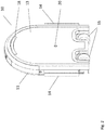
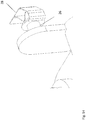
Figure 1 illustrates an embodiment of atransportation unit 10. Thetransportation unit 10 can be a part of a vehicle transportation arrangement for transportation of an object such as a vehicle on a surface alone or combined with other transportation units. The transportation unit may also be used alone or in combination with other transportation units to transport other objects. Thetransportation unit 10 comprises ahousing 11 having avertical front surface 12, twoarms 14 movably connected to thehousing 10 at each side of the vertical front surface, at least onerolling element 15 arranged at a lower portion of the housing, and a power source connected to the rolling elements and the movable arms. -
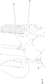
Figure 2 shows the same embodiment as infigure 10 , in rear view, showing theback surface 13 of the housing. - In the
housing 11 there are incorporated a number ofsensors front 17 and rear 18 sensors be cameras and theside sensors 16 be ultrasound sensors. The sensors can measure and monitor the distance to nearby objects and obstacles and are used for navigating to the desired position and to combine with other transportation units. - A
locking mechanism locking pin 20 which is adapted to be inserted and locked in ahole 19. - The
rolling elements 15 is in this embodiment wheels and can be rotated in order to enable rolling in any horizontal direction on the surface. In this way thetransportation unit 10 is very versatile and can navigate precisely from one position to another and position itself precisely with respect to other objects, walls or other obstacles. The rolling elements are connected to a driving unit such as a motor which in turn may be connected to a control unit which controls the driving unit and thereby the rolling elements. - The
arms 14 are designed to lift and hold the object to be transported. In the embodiment offigure 1 and2 , the arms are designed to lift a wheel for a car. Thearms 14 are thus shaped as longitudinal elements with a triangular cross section. In their resting position, thearms 14 are positioned along each side of thehousing 11, parallel to the sides, ie. arranged vertically. When preparing to lift the object to be transported, the arms will be lowered until they are parallel to the surface by rotation at themovable connection 21. The arms are in one embodiment rotated in a direction parallel to the front surface, but can in some embodiments be rotated perpendicular to the front surface. In the case where the arms are rotated parallel to the front surface, they can subsequently be rotated inwards, ie. towards each other to a defined transportation position. In the example of lifting a wheel, the arms are rotated until they are parallel to each other and perpendicular to the front surface. In one embodiment, the arms comprise a sensor which can detect when the arms meet resistance in order to stop the movement at contact. The arms will thus provide a support for the wheel. The arms will then continue with an upwards movement, thus lifting the wheel or other object to be transported. - The transportation arrangement may comprise at least one locking device configured to lock the arm(s) in a predetermined position.
- The
movable connection 21 of thearms 14 and the locking device are described in more detail infigures 8-19 . -
Figure 7 shows a section of one embodiment of anarm 14. The cross section has the same shape as theend face 74, which is triangular, and one of the side faces havegrooves 71 to provide friction and thus securing the arm's hold onto the object to be transported. The faces of the arms may also or instead be made of or covered by a friction material. At theend face 74 there is arranged a sensor device or a part of asensor device 72. In one embodiment a magnet is arranged in 72 which can be detected by a magnet sensor, for example arranged at the housing to detect when the arm is moved to a particular position at the side of the housing. -
Figure 10 shows a section of anarm 14 in its resting position, ie. arranged alongside thehousing 11. Thearms 14 are in one embodiment moved from their resting position by first lowering in an outwards direction parallel to the front surface as illustrated infigure 11 . When in the resting position, the magnet sensor registers the magnet on the arm, as shown infigure 7 . - Examples of a mechanism for lifting, rotating and lowering the
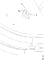
arms 14 is illustrated infigures 16-19 . The arms are in these illustrations lowered to a position mainly parallel to the transport surface. Infigure 19 , thearm 14 is illustrated during rotation from being parallel to the front surface to perpendicular to the front surface. Alocking mechanism arm 14 is rotated to its transporting position and will prevent the arms from moving outwards when weight is loaded onto the arms. In this way it is ensured that the arms stay in their transporting position and do not lose the object to be transported. When the arms are in position, they are lifted by further rotating thescrew 25. Afriction ring 24 causes the arms to first rotate to transporting position before the arms are lifted. When thearm 14 is to be folded up into its resting position again, it is first rotated outwards so that the length of the arm is parallel to the front surface and the ground (the surface on which the object are transported). In this position thepeg 26 will engage in thehole 27. The upwards rotation causing the arm to fold upwards, will occur due to the movement of the peg in thehole 27 where it engages a spring. The arm will then be further folded upwards and the to a position parallel to the front surface of the housing in a vertical position, ie. the resting position. An example of the different stages of this process is illustrated in more detail infigures 8-13 .Figures 14 and15 shows examples of aspring 28 which may be arranged in thehole 27 for engaging thepeg 26. - The two screws for rotating and lifting the two arms respectively, are threaded with opposite thread direction.
Figure 17 shows thearm 14 in transporting position and having being lifted by rotatingscrew 25. -
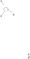
Figure 25 illustrates an alternative embodiment of a mechanism for movement of anarm 14 of a transportation unit. This embodiment comprises acogwheel 36 which are used for the lateral rotation of thearm 14. The use of acogwheel 36 eliminates the use of thefriction ring 24 infigures 16-19 . -
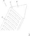
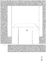
Figure 3 illustrates atransportation arrangement 30 which comprises fourtransportation units 10. The transportation units are in this example configured to lift and move each wheel of a car. - The
transportation units 10 each comprises a vertical back surface configured to contact the vertical front surface of another transportation unit. In this way the transportation units are stacked closely together and may me moved as one unit. - In
figure 3 , the transportation units are connected together by means of a locking mechanism arranged in each of the transportation units. The locking mechanism is configured to lock the transportation unit to another transportation unit and is exemplified and illustrated in more detail infigures 20-24 . - The part of the
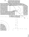
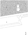
locking mechanism 19 arranged in the back of the transportation units comprises a lockingpin 21 which can be retracted into ahole 22 when not in use and can be extended from the hole when locking is needed.Figure 20 shows the locking pin in its retracted position. - In
figure 21 the lockingpin 21 of transport unit A is shown in its extended position, ready to be inserted and locked in lockinghole 19 of transport unit B.Figure 22 shows the locking pin inserted into lockinghole 19. Lockinghole 19 comprises a lockingspring 23, which will perform the locking function of the locking mechanism. After insertion of the locking pin, the locking pin can be rotated in order to perform the locking. In this example, the locking pin is rotated 90° between the locking position and the unlocked position. The lockingpin 21 is in its locking position when two transportation units are locked together and will be rotated 90° in order to release the transportation units from each other. - The rotated and locked situation is illustrated in
figure 23 .Figure 24 shows the lockingpin 21 in its locking orientation without being inserted into a locking hole. - In one embodiment, the four transportation units each comprises communication means and are configured to send and receive signals to and from the other transportation units. The communication means may also be able to communicate with remote units such as a remote control system, smart phones or tablets. The communication means are for example wireless transmitters and receivers. The signal may comprise information from the sensors on the transportation units, information regarding the rolling elements such as orientation, momentary rotational speed, status of the power source etc. At least one of the transportation units may comprise a processor device configured to process the signals from the sensors and other information from the transportation units. The transportation units may comprise a control device. One of the transportation units may thus be a master unit, which can send control signals to the other transportation units, which then will function as slave units. When the transportation units are in a transportation arrangement as described, the control signals will direct each of the transportation units to perform its dedicated transport operation. In the example of the transportation arrangement being configured to lift and move each wheel of a car, the transportation units are directed to the wheels and will lift the wheels, and thus the car, in a coordinated manner.
- For example, movement instructions are sent to a control device in the transportation units by means of a wireless transmitter. The control device, which is connected to a receiver, may comprise a micro-controller interpreting and acting to a transmitted sequence comprising driving instructions.
- When the control device of the transportation unit receives movement instructions, it will determine its position relative to its surroundings. This is current and first position.
- When current position is established, movement instruction for controlling the movement of the rolling element is executed in the control device. The movements are based on said first position of the rolling arrangement and the received movement instructions comprising a second position.
- Based on this, the transportation unit is moved from the first to the second position.
- In one embodiment, a selected transportation unit is set to act as a master unit controlling the movements of the other transportation units. These will then act as slave devices and respond to instructions from the master unit. The master unit will then transmit control signals to the slave devices instructing them it to follow movements according to individual target positions. When several transportation units are to be included in a transportation arrangement that is to be simultaneously and coordinated controlled, each transportation unit is given a unique ID. In this way, all transportation units are able to receive individual movement instructions.
- When one transportation unit is acting as a master for the others, it will control each of the other transportation units connected to same device.
- When the transportation units are used for other purposes, or acting alone, each transportation unit may still comprise communication means and be remotely controlled.
-
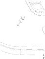
Figure 4 illustrates a transportation unit prepared for wireless charging. The power source is a chargeable battery arranged inside the housing. Thecircular charging field 41 illustrates the area where the battery is located. The battery can then be charged by placing a wireless charger adjacent to the charging field. The wireless charger can for example be integrated in a wall or a docking station and thetransportation unit 10 can roll to the wireless charger when re-charging is needed. -
Figure 5 and6 illustrates a transportation unit where the power source is aremovable battery 51. Thebattery 51 can be inserted into abattery slot 53 in thehousing 11 by use ofgripping holes 52 and removed when it needs to be charged or replaced. There may also be arranged electric connectors in thegripping holes 52 for connection to electrical power for direct charging of thebattery 52. - The transportation unit may be so-called self-balancing. This means that the rolling elements are engaged when the angle of the transportation unit relative the surface on which it will transport any object changes.
- In order to achieve self-balancing, the transportation unit comprises a self-balancing control mechanism configured to keep the position of the vertical front surface substantially constant. The self-balancing control mechanism comprises for example a gyroscopic and a sensor. Motors driving the rolling elements automatically engage the gyroscope in the opposite direction of a movement detected by the sensor.
- An example of a self-balancing control mechanism is used in hoverboards. The wheels of the hoverboard house the electric motors themselves. They also contain a tilt and speed sensor. The tilt and speed sensors detect the rpm (revolutions per minute) of the individual wheel, and sends it to the gyroscope and speed control boards, located inside the main body, right next to the wheels.
- The gyroscope and speed control boards receive the rpms and tilt information from the sensor inside the wheels, and they, in turn, send it to the main logic board.
- The tilt sensors in the wheels tell the gyroscopes how far forward you're leaning. The gyroscopes relay this information to the logic board.
- The more you're leaning forward, the faster the logic board tells the motors to spin, to sort of "catch up" with your center of gravity.
Claims (9)
- Transportation arrangement for transportation of an object on a surface, the transportation arrangement comprising at least one transportation unit (10) comprising- a housing (11) comprising a vertical front surface, two arms movably connected to the housing at each side of the vertical front surface, at least one rolling element (12) arranged at a lower portion of the housing, and a power source connected to the rolling elements and the movable arms, where the rolling element are configured to roll in any horizontal direction on the surface.
- Transportation arrangement according claim 1, comprising at least one locking device configured to lock the arm(s) in a predetermined position.
- Transportation arrangement according to any of the previous claims, where the transportation unit comprises at least one sensor device configured to measure the distance between the transportation unit and surrounding objects.
- Transportation arrangement according to any of the previous claims, where the at least one transportation unit comprises a self-balancing control mechanism configured to keep the position of the vertical front surface substantially constant.
- Transportation arrangement according to any of the previous claims, where the power source is a removable battery.
- Transportation arrangement according to any of the previous claims, comprising four transportation units, the transportation units being configured to lift and move each wheel of a car.
- Transportation arrangement according to claim 6, where the four transportation units each comprise communication means and are configured to send and receive signals to and from the other transportation units.
- Transportation arrangement according to claim 6 or 7, where the transportation units comprise a vertical back surface configured to contact the vertical front surface of another transportation unit.
- Transportation arrangement according to one of claims 6-8, where the transportation units each comprises a locking mechanism configured to lock the transportation unit to another transportation unit.
Priority Applications (8)
| Application Number | Priority Date | Filing Date | Title |
|---|---|---|---|
| EP24150432.3A EP4345053A2 (en) | 2019-07-16 | 2019-07-16 | Transportation arrangement for transportation of an object on a surface |
| EP19186556.7A EP3766748A1 (en) | 2019-07-16 | 2019-07-16 | Transportation arrangement for transportation of an object on a surface |
| US17/626,983 US20220258821A1 (en) | 2019-07-16 | 2020-07-03 | Transportation arrangement for transportation of an object on a surface |
| CN202080051404.7A CN114126991B (en) | 2019-07-16 | 2020-07-03 | Transport device for transporting objects on a surface |
| JP2022502412A JP2022541033A (en) | 2019-07-16 | 2020-07-03 | Transfer device for transfer of objects on surfaces |
| KR1020227004206A KR20220073726A (en) | 2019-07-16 | 2020-07-03 | Transport device for transport of objects on a surface |
| PCT/EP2020/068851 WO2021008905A1 (en) | 2019-07-16 | 2020-07-03 | Transportation arrangement for transportation of an object on a surface |
| CA3147323A CA3147323A1 (en) | 2019-07-16 | 2020-07-03 | Transportation arrangement for transportation of an object on a surface |
Applications Claiming Priority (1)
| Application Number | Priority Date | Filing Date | Title |
|---|---|---|---|
| EP19186556.7A EP3766748A1 (en) | 2019-07-16 | 2019-07-16 | Transportation arrangement for transportation of an object on a surface |
Related Child Applications (1)
| Application Number | Title | Priority Date | Filing Date |
|---|---|---|---|
| EP24150432.3A Division EP4345053A2 (en) | 2019-07-16 | 2019-07-16 | Transportation arrangement for transportation of an object on a surface |
Publications (1)
| Publication Number | Publication Date |
|---|---|
| EP3766748A1 true EP3766748A1 (en) | 2021-01-20 |
Family
ID=67437805
Family Applications (2)
| Application Number | Title | Priority Date | Filing Date |
|---|---|---|---|
| EP19186556.7A Pending EP3766748A1 (en) | 2019-07-16 | 2019-07-16 | Transportation arrangement for transportation of an object on a surface |
| EP24150432.3A Pending EP4345053A2 (en) | 2019-07-16 | 2019-07-16 | Transportation arrangement for transportation of an object on a surface |
Family Applications After (1)
| Application Number | Title | Priority Date | Filing Date |
|---|---|---|---|
| EP24150432.3A Pending EP4345053A2 (en) | 2019-07-16 | 2019-07-16 | Transportation arrangement for transportation of an object on a surface |
Country Status (7)
| Country | Link |
|---|---|
| US (1) | US20220258821A1 (en) |
| EP (2) | EP3766748A1 (en) |
| JP (1) | JP2022541033A (en) |
| KR (1) | KR20220073726A (en) |
| CN (1) | CN114126991B (en) |
| CA (1) | CA3147323A1 (en) |
| WO (1) | WO2021008905A1 (en) |
Families Citing this family (1)
| Publication number | Priority date | Publication date | Assignee | Title |
|---|---|---|---|---|
| DE102022211486A1 (en) * | 2022-10-28 | 2024-05-08 | Robert Bosch Gesellschaft mit beschränkter Haftung | Jack |
Citations (6)
| Publication number | Priority date | Publication date | Assignee | Title |
|---|---|---|---|---|
| GB2528987A (en) * | 2014-08-08 | 2016-02-10 | John Reynolds | A Motorised Skate for a Vehicle |
| US9376132B1 (en) * | 2015-06-26 | 2016-06-28 | Mvp (H.K.) Industries Limited | Car dolly and methods of making and using same |
| WO2017207978A1 (en) * | 2016-05-31 | 2017-12-07 | Arrival Limited | Autonomous container transportation vehicle |
| CN107444362A (en) * | 2017-07-24 | 2017-12-08 | 湖北工业大学 | A kind of family expenses move car device |
| EP3431323A1 (en) * | 2017-07-17 | 2019-01-23 | Robert Bosch GmbH | A method and a device for operating a power-driven vehicle within an urban area |
| DE102017221654A1 (en) * | 2017-10-06 | 2019-04-11 | Zf Friedrichshafen Ag | Parking vehicle and method for transporting and parking a vehicle |
Family Cites Families (13)
| Publication number | Priority date | Publication date | Assignee | Title |
|---|---|---|---|---|
| NL1005284C1 (en) * | 1997-02-14 | 1998-08-18 | Itrec Bv | Transport vehicle for large heavy loads. |
| US6733226B1 (en) * | 2003-02-07 | 2004-05-11 | Pete J. Bonin | Vehicle moving apparatus |
| JP4565107B2 (en) * | 2005-08-31 | 2010-10-20 | 株式会社東芝 | Mobile robot with arm mechanism |
| DE202014000755U1 (en) * | 2014-01-30 | 2015-05-04 | Hit Hafen- Und Industrietechnik Gmbh | Heavy-duty low-floor vehicle, and system with one or more of these vehicles |
| JP6378527B2 (en) * | 2014-04-28 | 2018-08-22 | 新明和工業株式会社 | Tire clamping apparatus and automobile conveying apparatus equipped with the same |
| NO337544B1 (en) * | 2014-06-19 | 2016-05-02 | Jakob Hatteland Logistics As | Remote controlled vehicle assembly to pick up storage containers from a storage system |
| CN104742671B (en) * | 2015-04-15 | 2017-04-05 | 同方威视技术股份有限公司 | Vehicle tractor and vehicle traction method |
| JP2016216936A (en) * | 2015-05-15 | 2016-12-22 | 株式会社デンソー | Vehicle conveyance device |
| CN105014640A (en) * | 2015-07-23 | 2015-11-04 | 广西柳拖车辆有限公司 | Transport cart for electric automobile body punching dies |
| DE102017217827A1 (en) * | 2017-10-06 | 2019-04-11 | Zf Friedrichshafen Ag | Parking vehicle and method for transporting and parking a vehicle |
| CN107934842A (en) * | 2017-12-20 | 2018-04-20 | 湖北赞博信息科技股份有限公司 | A kind of electronic handling device of light cargo |
| CN108100058B (en) * | 2017-12-27 | 2023-10-10 | 清华大学 | Fork arm lifting type tractor |
| CN108466980B (en) * | 2018-06-26 | 2020-05-01 | 泰州市惠泽机械有限公司 | Carrying machine with fork folding function |
-
2019
- 2019-07-16 EP EP19186556.7A patent/EP3766748A1/en active Pending
- 2019-07-16 EP EP24150432.3A patent/EP4345053A2/en active Pending
-
2020
- 2020-07-03 US US17/626,983 patent/US20220258821A1/en active Pending
- 2020-07-03 WO PCT/EP2020/068851 patent/WO2021008905A1/en active Application Filing
- 2020-07-03 KR KR1020227004206A patent/KR20220073726A/en unknown
- 2020-07-03 CA CA3147323A patent/CA3147323A1/en active Pending
- 2020-07-03 CN CN202080051404.7A patent/CN114126991B/en active Active
- 2020-07-03 JP JP2022502412A patent/JP2022541033A/en active Pending
Patent Citations (6)
| Publication number | Priority date | Publication date | Assignee | Title |
|---|---|---|---|---|
| GB2528987A (en) * | 2014-08-08 | 2016-02-10 | John Reynolds | A Motorised Skate for a Vehicle |
| US9376132B1 (en) * | 2015-06-26 | 2016-06-28 | Mvp (H.K.) Industries Limited | Car dolly and methods of making and using same |
| WO2017207978A1 (en) * | 2016-05-31 | 2017-12-07 | Arrival Limited | Autonomous container transportation vehicle |
| EP3431323A1 (en) * | 2017-07-17 | 2019-01-23 | Robert Bosch GmbH | A method and a device for operating a power-driven vehicle within an urban area |
| CN107444362A (en) * | 2017-07-24 | 2017-12-08 | 湖北工业大学 | A kind of family expenses move car device |
| DE102017221654A1 (en) * | 2017-10-06 | 2019-04-11 | Zf Friedrichshafen Ag | Parking vehicle and method for transporting and parking a vehicle |
Also Published As
| Publication number | Publication date |
|---|---|
| JP2022541033A (en) | 2022-09-21 |
| CN114126991A (en) | 2022-03-01 |
| CA3147323A1 (en) | 2021-01-21 |
| KR20220073726A (en) | 2022-06-03 |
| CN114126991B (en) | 2024-04-26 |
| WO2021008905A1 (en) | 2021-01-21 |
| EP4345053A2 (en) | 2024-04-03 |
| US20220258821A1 (en) | 2022-08-18 |
Similar Documents
| Publication | Publication Date | Title |
|---|---|---|
| EP2976687B1 (en) | Systems and methods for uav docking | |
| CN112004695A (en) | System and method for automated handling and processing of automotive trucks and tractor-trailers | |
| US20180196418A1 (en) | Method for unattended operations using autonomous or remotely operated vehicles | |
| US20190092447A1 (en) | Multirotor aircraft | |
| US10139816B2 (en) | Device for maneuvering ground support equipment on an airport stand | |
| EP3267189B1 (en) | Defect inspection device, defect inspection method, and program | |
| CN108058605A (en) | For pair can electrically drivable motor vehicle supply of electrical energy amount energy supply vehicle | |
| JP2023009063A (en) | Vehicle transportation system | |
| CN110997398A (en) | Parking vehicle, method for parking an electric vehicle and for charging a battery of an electric vehicle, and parking space system | |
| CN111619525A (en) | Vehicle transport device | |
| US20220258821A1 (en) | Transportation arrangement for transportation of an object on a surface | |
| ES2906864T3 (en) | Procedure and vehicle for transporting an electrically powered motor vehicle during assembly | |
| US20230271657A1 (en) | An Autonomous Mobile System, For Use In An Industrial Plant As A Reconfigurable Operating System | |
| JP2022189891A (en) | Vehicle transportation device | |
| US20150239473A1 (en) | Vehicle guidance system and corresponding method | |
| FR3066052B1 (en) | BATTERY INDUCTION RECHARGING DEVICE (S) OF A VEHICLE WITH MULTIPLE POWER OUTLETS FOR A MOBILE HOUSING | |
| CN108749593B (en) | A kind of wireless charging system for electric automobile | |
| JPWO2020013337A1 (en) | Traveling system for moving vehicles | |
| CN115196264B (en) | Cooperative carrying robot with vehicle-mounted clamp holder and control method thereof | |
| KR20220164479A (en) | Transport devices for transporting objects on surfaces | |
| US20240077572A1 (en) | Control of the movement of a mobile unit towards an object by analyzing radio and acoustic signals | |
| CN111032979A (en) | Running platform for motor vehicle transportation |
Legal Events
| Date | Code | Title | Description |
|---|---|---|---|
| PUAI | Public reference made under article 153(3) epc to a published international application that has entered the european phase |
Free format text: ORIGINAL CODE: 0009012 |
|
| STAA | Information on the status of an ep patent application or granted ep patent |
Free format text: STATUS: THE APPLICATION HAS BEEN PUBLISHED |
|
| AK | Designated contracting states |
Kind code of ref document: A1 Designated state(s): AL AT BE BG CH CY CZ DE DK EE ES FI FR GB GR HR HU IE IS IT LI LT LU LV MC MK MT NL NO PL PT RO RS SE SI SK SM TR |
|
| AX | Request for extension of the european patent |
Extension state: BA ME |
|
| STAA | Information on the status of an ep patent application or granted ep patent |
Free format text: STATUS: REQUEST FOR EXAMINATION WAS MADE |
|
| 17P | Request for examination filed |
Effective date: 20210720 |
|
| RBV | Designated contracting states (corrected) |
Designated state(s): AL AT BE BG CH CY CZ DE DK EE ES FI FR GB GR HR HU IE IS IT LI LT LU LV MC MK MT NL NO PL PT RO RS SE SI SK SM TR |
|
| STAA | Information on the status of an ep patent application or granted ep patent |
Free format text: STATUS: EXAMINATION IS IN PROGRESS |
|
| 17Q | First examination report despatched |
Effective date: 20220126 |
|
| RAP3 | Party data changed (applicant data changed or rights of an application transferred) |
Owner name: WHEEL.ME AS |
|
| RIN1 | Information on inventor provided before grant (corrected) |
Inventor name: LIBAKKEN, ROLF |
|
| RAP3 | Party data changed (applicant data changed or rights of an application transferred) |
Owner name: WHEEL.ME AS |