EP3358306B1 - Vehicle control apparatus and vehicle control method - Google Patents
Vehicle control apparatus and vehicle control method Download PDFInfo
- Publication number
- EP3358306B1 EP3358306B1 EP18153199.7A EP18153199A EP3358306B1 EP 3358306 B1 EP3358306 B1 EP 3358306B1 EP 18153199 A EP18153199 A EP 18153199A EP 3358306 B1 EP3358306 B1 EP 3358306B1
- Authority
- EP
- European Patent Office
- Prior art keywords
- vehicle
- standby
- information
- demand prediction
- moving
- Prior art date
- Legal status (The legal status is an assumption and is not a legal conclusion. Google has not performed a legal analysis and makes no representation as to the accuracy of the status listed.)
- Active
Links
- 238000000034 method Methods 0.000 title claims description 29
- 238000009826 distribution Methods 0.000 claims description 71
- 230000008859 change Effects 0.000 claims description 4
- 238000004590 computer program Methods 0.000 claims description 3
- 238000003032 molecular docking Methods 0.000 description 25
- 238000011156 evaluation Methods 0.000 description 17
- 238000010586 diagram Methods 0.000 description 16
- 238000012545 processing Methods 0.000 description 15
- 238000003860 storage Methods 0.000 description 13
- 230000006870 function Effects 0.000 description 10
- 239000000470 constituent Substances 0.000 description 8
- 230000008901 benefit Effects 0.000 description 6
- 238000004891 communication Methods 0.000 description 5
- 230000007423 decrease Effects 0.000 description 4
- 230000033001 locomotion Effects 0.000 description 4
- 238000010801 machine learning Methods 0.000 description 3
- 230000008569 process Effects 0.000 description 3
- 238000004364 calculation method Methods 0.000 description 2
- 230000010354 integration Effects 0.000 description 2
- 230000004048 modification Effects 0.000 description 2
- 238000012986 modification Methods 0.000 description 2
- 230000029305 taxis Effects 0.000 description 2
- 239000000446 fuel Substances 0.000 description 1
- 238000004519 manufacturing process Methods 0.000 description 1
- 239000000463 material Substances 0.000 description 1
- 238000003825 pressing Methods 0.000 description 1
- 230000004044 response Effects 0.000 description 1
- 239000004065 semiconductor Substances 0.000 description 1
- 239000000725 suspension Substances 0.000 description 1
Images


Classifications
-
- G—PHYSICS
- G01—MEASURING; TESTING
- G01C—MEASURING DISTANCES, LEVELS OR BEARINGS; SURVEYING; NAVIGATION; GYROSCOPIC INSTRUMENTS; PHOTOGRAMMETRY OR VIDEOGRAMMETRY
- G01C21/00—Navigation; Navigational instruments not provided for in groups G01C1/00 - G01C19/00
- G01C21/26—Navigation; Navigational instruments not provided for in groups G01C1/00 - G01C19/00 specially adapted for navigation in a road network
- G01C21/34—Route searching; Route guidance
- G01C21/3407—Route searching; Route guidance specially adapted for specific applications
-
- G—PHYSICS
- G06—COMPUTING; CALCULATING OR COUNTING
- G06Q—INFORMATION AND COMMUNICATION TECHNOLOGY [ICT] SPECIALLY ADAPTED FOR ADMINISTRATIVE, COMMERCIAL, FINANCIAL, MANAGERIAL OR SUPERVISORY PURPOSES; SYSTEMS OR METHODS SPECIALLY ADAPTED FOR ADMINISTRATIVE, COMMERCIAL, FINANCIAL, MANAGERIAL OR SUPERVISORY PURPOSES, NOT OTHERWISE PROVIDED FOR
- G06Q10/00—Administration; Management
- G06Q10/04—Forecasting or optimisation specially adapted for administrative or management purposes, e.g. linear programming or "cutting stock problem"
- G06Q10/047—Optimisation of routes or paths, e.g. travelling salesman problem
-
- B—PERFORMING OPERATIONS; TRANSPORTING
- B60—VEHICLES IN GENERAL
- B60R—VEHICLES, VEHICLE FITTINGS, OR VEHICLE PARTS, NOT OTHERWISE PROVIDED FOR
- B60R25/00—Fittings or systems for preventing or indicating unauthorised use or theft of vehicles
- B60R25/20—Means to switch the anti-theft system on or off
- B60R25/23—Means to switch the anti-theft system on or off using manual input of alphanumerical codes
-
- G—PHYSICS
- G01—MEASURING; TESTING
- G01C—MEASURING DISTANCES, LEVELS OR BEARINGS; SURVEYING; NAVIGATION; GYROSCOPIC INSTRUMENTS; PHOTOGRAMMETRY OR VIDEOGRAMMETRY
- G01C21/00—Navigation; Navigational instruments not provided for in groups G01C1/00 - G01C19/00
- G01C21/26—Navigation; Navigational instruments not provided for in groups G01C1/00 - G01C19/00 specially adapted for navigation in a road network
- G01C21/34—Route searching; Route guidance
- G01C21/3407—Route searching; Route guidance specially adapted for specific applications
- G01C21/3438—Rendez-vous, i.e. searching a destination where several users can meet, and the routes to this destination for these users; Ride sharing, i.e. searching a route such that at least two users can share a vehicle for at least part of the route
-
- G—PHYSICS
- G01—MEASURING; TESTING
- G01C—MEASURING DISTANCES, LEVELS OR BEARINGS; SURVEYING; NAVIGATION; GYROSCOPIC INSTRUMENTS; PHOTOGRAMMETRY OR VIDEOGRAMMETRY
- G01C21/00—Navigation; Navigational instruments not provided for in groups G01C1/00 - G01C19/00
- G01C21/26—Navigation; Navigational instruments not provided for in groups G01C1/00 - G01C19/00 specially adapted for navigation in a road network
- G01C21/34—Route searching; Route guidance
- G01C21/36—Input/output arrangements for on-board computers
- G01C21/3679—Retrieval, searching and output of POI information, e.g. hotels, restaurants, shops, filling stations, parking facilities
- G01C21/3685—Retrieval, searching and output of POI information, e.g. hotels, restaurants, shops, filling stations, parking facilities the POI's being parking facilities
-
- G—PHYSICS
- G05—CONTROLLING; REGULATING
- G05D—SYSTEMS FOR CONTROLLING OR REGULATING NON-ELECTRIC VARIABLES
- G05D1/00—Control of position, course, altitude or attitude of land, water, air or space vehicles, e.g. using automatic pilots
- G05D1/0088—Control of position, course, altitude or attitude of land, water, air or space vehicles, e.g. using automatic pilots characterized by the autonomous decision making process, e.g. artificial intelligence, predefined behaviours
-
- G—PHYSICS
- G06—COMPUTING; CALCULATING OR COUNTING
- G06Q—INFORMATION AND COMMUNICATION TECHNOLOGY [ICT] SPECIALLY ADAPTED FOR ADMINISTRATIVE, COMMERCIAL, FINANCIAL, MANAGERIAL OR SUPERVISORY PURPOSES; SYSTEMS OR METHODS SPECIALLY ADAPTED FOR ADMINISTRATIVE, COMMERCIAL, FINANCIAL, MANAGERIAL OR SUPERVISORY PURPOSES, NOT OTHERWISE PROVIDED FOR
- G06Q30/00—Commerce
- G06Q30/02—Marketing; Price estimation or determination; Fundraising
- G06Q30/0283—Price estimation or determination
- G06Q30/0284—Time or distance, e.g. usage of parking meters or taximeters
-
- G—PHYSICS
- G06—COMPUTING; CALCULATING OR COUNTING
- G06Q—INFORMATION AND COMMUNICATION TECHNOLOGY [ICT] SPECIALLY ADAPTED FOR ADMINISTRATIVE, COMMERCIAL, FINANCIAL, MANAGERIAL OR SUPERVISORY PURPOSES; SYSTEMS OR METHODS SPECIALLY ADAPTED FOR ADMINISTRATIVE, COMMERCIAL, FINANCIAL, MANAGERIAL OR SUPERVISORY PURPOSES, NOT OTHERWISE PROVIDED FOR
- G06Q30/00—Commerce
- G06Q30/06—Buying, selling or leasing transactions
- G06Q30/0645—Rental transactions; Leasing transactions
-
- G—PHYSICS
- G08—SIGNALLING
- G08G—TRAFFIC CONTROL SYSTEMS
- G08G1/00—Traffic control systems for road vehicles
-
- G—PHYSICS
- G08—SIGNALLING
- G08G—TRAFFIC CONTROL SYSTEMS
- G08G1/00—Traffic control systems for road vehicles
- G08G1/123—Traffic control systems for road vehicles indicating the position of vehicles, e.g. scheduled vehicles; Managing passenger vehicles circulating according to a fixed timetable, e.g. buses, trains, trams
- G08G1/127—Traffic control systems for road vehicles indicating the position of vehicles, e.g. scheduled vehicles; Managing passenger vehicles circulating according to a fixed timetable, e.g. buses, trains, trams to a central station ; Indicators in a central station
-
- G—PHYSICS
- G08—SIGNALLING
- G08G—TRAFFIC CONTROL SYSTEMS
- G08G1/00—Traffic control systems for road vehicles
- G08G1/14—Traffic control systems for road vehicles indicating individual free spaces in parking areas
- G08G1/145—Traffic control systems for road vehicles indicating individual free spaces in parking areas where the indication depends on the parking areas
- G08G1/148—Management of a network of parking areas
-
- G—PHYSICS
- G08—SIGNALLING
- G08G—TRAFFIC CONTROL SYSTEMS
- G08G1/00—Traffic control systems for road vehicles
- G08G1/20—Monitoring the location of vehicles belonging to a group, e.g. fleet of vehicles, countable or determined number of vehicles
-
- G—PHYSICS
- G08—SIGNALLING
- G08G—TRAFFIC CONTROL SYSTEMS
- G08G1/00—Traffic control systems for road vehicles
- G08G1/20—Monitoring the location of vehicles belonging to a group, e.g. fleet of vehicles, countable or determined number of vehicles
- G08G1/202—Dispatching vehicles on the basis of a location, e.g. taxi dispatching
Definitions
- the present disclosure relates to a vehicle control apparatus and a vehicle control method for causing, when a vehicle that is capable of traveling autonomously Is dropped off, the vehicle to move a standby place In an unmanned manner.
- Patent Document 1 discloses a system using a self-driving vehicle (such as an electric car) that can travel autonomously.
- the self-driving vehicle disclosed in Patent Document 1 receives settings for an operation after a user gets out of the self-driving vehicle.
- Patent Document 1 also discloses that when the operation after the user gets out of the self-driving vehicle is set to "return", the self-driving vehicle returns to a predetermined return place, such as a parking lot of a nearest car rental company, after the self-driving vehicle Is dropped off.
- Patent Application US 2015/0199619 A1 relates to management of reservation and parking of autonomous electrical-powered vehicles traveling along a destination route.
- the vehicle communicates with a management center, which sends operation instructions to the vehicle.
- a management center which sends operation instructions to the vehicle.
- a user is dropped off or picked up by the vehicle and the vehicle autonomously drives to large or small waiting areas to park the vehicle.
- the route to the waiting area (destination) is selected based on the state of the vehicle (e.g. current GPS location, remaining energy), the energy characteristics of the vehicle, energy required for traveling the route, and traveling time.
- the waiting areas are equipped with charging devices for recharging the vehicle. If the remaining energy is less than the travel energy, a reservation request is not possible and the user has to modify the usage settings, including a change of vehicle or content modification. Otherwise, the vehicle receives instructions commands from the management center.
- Patent Application US 2016/0343068 A1 relates to automated vehicle rental and rebalancing usage of vehicle pickup/return stations. For each station, the number of available cars, an average waiting time for the vehicle at the station, an average return time for the vehicle to return to the station, the number of vehicles in a zone closest to the station, and the flow based on the average waiting and return times are calculated. These data are stored in a database. The station is added or removed from a list of departure stations or a list of arrival stations, based on determined occupancy rates (OR) and relief rates (RR). To avoid an unbalanced distribution of used and empty stations, a rebalancing of the stations is performed by selecting the vehicle movement to a station in relation to a balancing time and location.
- OR occupancy rates
- RR relief rates
- Patent Application WO 2016/147368 A1 relates to operation control of a vehicle having an automatic driving function that facilitates parking by automated searching for a parking lot using travel information of the vehicle, including position and speed of the vehicle. When a parking space not being in a prohibited parking area is found, the vehicle is parked automatically.
- One non-limiting and exemplary embodiment provides a vehicle control apparatus or a vehicle control method that can allocate a dropped of vehicle to an appropriate location.
- the techniques disclosed here feature an apparatus according to claim 1.
- the present disclosure can provide a vehicle control apparatus or a vehicle control method that can allocate a dropped off vehicle to an appropriate location.
- a vehicle control apparatus is directed to a vehicle control apparatus that causes, when a vehicle that is capable of traveling autonomously is dropped off, the vehicle to move to a standby place by traveling autonomously.
- the apparatus includes: a moving-destination determiner that determines, when the vehicle is dropped off, a moving destination among a plurality of standby places, based on a current location of the vehicle, locations of the standby places, and vehicle-demand prediction information; and a moving instructor that instructs the vehicle to move to the determined moving destination.
- the vehicle control apparatus can allocate a dropped off vehicle to an appropriate location by using the vehicle-demand prediction information. Also, since the appropriate location can be determined in such a manner, re-moving the vehicle or the like can be suppressed or reduced, and thus the amount of fuel consumed by the vehicle can be reduced. In addition, since re-performing a computational operation, re-issuing an instruction, and so on can be suppressed, it is possible to reduce throughput of the vehicle control apparatus.
- the moving-destination determiner may determine, among the standby places, moving-destination candidates included in a predetermined range from the current location and may determine the moving destination among the moving-destination candidates, based on the demand prediction information.
- the vehicle may be an electrically powered vehicle; battery chargers for the vehicle is provided at the standby places; and when the vehicle is dropped off, the moving-destination determiner may determine the moving destination, based on the current location, the locations of the standby places, the demand prediction information, and a current battery charge of the vehicle.
- the vehicle control apparatus can allocate a dropped off vehicle to an appropriate location, based on the battery charge of the vehicle.
- the moving-destination determiner may determine, among the standby places, the moving-destination candidates included in a range that the vehicle is capable of traveling from the current location by using the current battery charge and may determine the moving destination among the moving-destination candidates, based on the demand prediction information.
- the moving-destination determiner may determine, the moving destination, based on the current location, the locations of the standby places, the demand prediction information, and information about a plurality of vehicles.
- the vehicle control apparatus can allocate a dropped off vehicle to an appropriate location by using the information about a plurality of vehicles.
- the vehicle control apparatus may further include a demand predictor that determines the demand prediction information, based on population information.
- the vehicle control apparatus can generate appropriate demand prediction information.
- the vehicle control apparatus may further include a demand predictor that determines dynamic demand prediction information, based on dynamic power consumption data.
- this vehicle control apparatus can generate dynamic demand prediction information based on power consumption data.
- the vehicle control apparatus may further include a demand predictor that that determines the dynamic demand prediction information, based on dynamic sales data of stores.
- the vehicle control apparatus can generate dynamic demand prediction information based on sales data.
- the vehicle control apparatus may further include a demand predictor that determines the dynamic demand prediction information, based on weather forecast information.
- the vehicle control apparatus can generate dynamic demand prediction information based on weather forecast information.
- the vehicle control apparatus may further include a drop-off determiner that determines whether or not the vehicle is dropped off, based on a state of the vehicle.
- the state of the vehicle may include at least one of a speed of the vehicle, a change in weight applied to the vehicle, opening and closing of a door, and locking of a door.
- the vehicle control apparatus can appropriately determine drop-off of a vehicle.
- a vehicle control method is directed to a vehicle control method that causes, when a vehicle that is capable of traveling autonomously is dropped off, the vehicle to move to a standby place by traveling autonomously.
- the method includes: determining, when a vehicle that is capable of traveling autonomously is dropped off, a moving destination among a plurality of standby places, based on a current location of the vehicle which is indicated by a global positioning system provided in the vehicle, locations of the standby places, and vehicle-demand prediction information; and instructing the vehicle to move to the determined moving destination.
- the vehicle control method it is possible to allocate a dropped off vehicle to an appropriate location by using the vehicle-demand prediction information.
- the configuration for allocating a vehicle to an appropriate location by using the vehicle-demand prediction information can also be applied to a bicycle sharing system.
- the bicycle sharing system includes: an incentive determiner that determines an incentive to be given to a user when the user moves a bicycle to a moving destination that is one of standby places, based on the number of bicycles on standby at each of the standby places and bicycle-demand prediction information, and an informer that informs the user of the moving destination and the incentive.
- the bicycle sharing system can guide users so that vehicles are allocated to appropriate locations. Since the appropriate locations can be determined in such a manner, it is possible to suppress re-performing a computational operation, re-issuing an instruction, and so on, thus making it possible to reduce throughput of a control apparatus.
- vehicle i.e., bicycle
- the incentive determiner may increase the incentive, as the distance from the current location of the bicycle to the moving destination increases.
- the bicycle sharing system can determine an appropriate incentive.
- the incentive determiner may increase the incentive, as the number of bicycles that are present at the moving destination gets smaller relative to demand prediction for the moving destination, the demand prediction being indicated by the demand prediction information.
- the bicycle sharing system can guide users so that the vehicles are allocated to more appropriate locations.
- a bicycle sharing system may include: determining an incentive to be given to a user when the user moves a bicycle to a moving destination that is one of standby places, based on the number of bicycles on standby at each of the standby places and bicycle-demand prediction information, and informing the user of the moving destination and the incentive.
- the bicycle sharing method by using the vehicle (i.e., bicycle) demand prediction information, it is possible to guide users so that the vehicles are allocated to appropriate locations.
- vehicle i.e., bicycle
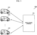
- Fig. 1 is a diagram illustrating the configuration of a vehicle control system 100 according to the first embodiment.
- the vehicle control system 100 includes a plurality of vehicles 102 and a vehicle control apparatus 101 that controls the vehicles 102.
- Each of the vehicles 102 is, for example, an electrically powered vehicle, such as an electric vehicle, having an autonomous driving function and can travel autonomously (e.g., in an unmanned manner).
- an electrically powered vehicle such as an electric vehicle, having an autonomous driving function and can travel autonomously (e.g., in an unmanned manner).
- each vehicle 102 can be parked or charged in small space in a town.
- users can use the vehicles 102 parked at various standby places in the town.
- each user rides one of the vehicles 102 that are parked and sets a destination.
- the vehicle 102 travels autonomously to the set destination while the user is in the vehicle 102.
- the user may pre-set the destination via a portable terminal or the like, before he or she gets in the vehicle 102.
- the vehicle 102 travels autonomously to one of the standby places, stands by, and performs charging.
- a user getting out of the vehicle 102 at a destination is herein referred to as "drop off".
- the vehicle 102 may be driven by the user, rather than traveling autonomously.
- the vehicle 102 may move to a pickup place designated by the user by traveling autonomously, on the basis of the user's instruction given or reservation made via a portable terminal or the like.
- the vehicle 102 may move, by traveling autonomously, the vehicle 102 closest to a pickup place designated by the user to the pickup place by.
- the vehicle 102 that moves to the pickup place may be determined based on a destination set by the user, rather than moving the vehicle 102 closest to the pickup place designated by the user. For example, when the vehicle 102 that is being sent toward a place in the vicinity of a destination set by the user is moved to a pickup place by traveling autonomously, it is possible to realize efficient vehicle dispatch.
- Each of the standby places is not limited to a private parking space like that illustrated in Fig. 2 and may be a parking space where a business operator runs a parking-lot business, a public parking space, or the like.
- battery chargers for the vehicles 102 are provided at the standby places.
- each vehicle 102 is automatically charged by a method in which a charging connector is physically connected thereto or by a method using contactless charging. Work for the charging may be partly or entirely performed by personnel who are present at each standby place.
- the vehicle control apparatus 101 can communicate with the vehicles 102 through a communication network or the like. When one of the vehicles 102 is dropped off, the vehicle control apparatus 101 causes the vehicle 102 to move to a standby place by traveling autonomously (e.g., in an unmanned manner).
- Fig. 3 is a block diagram illustrating the configuration of the vehicle control apparatus 101.
- the vehicle control apparatus 101 includes a vehicle information obtainer 111, a drop-off determiner 112, a storage unit 113, a moving-destination determiner 114, a moving instructor 115, a standby-place manager 116, a demand predictor 117, and a vehicle information manager 118.
- the vehicle information obtainer 111 obtains vehicle state information from each vehicle 102.
- the vehicle state information indicates, for example, the state and the location of each vehicle 102.
- the drop-off determiner 112 determines whether or not the vehicle 102 is dropped off.
- the storage unit 113 stores therein standby-place information 121 indicating the locations of standby places, demand prediction information 122 indicating vehicle-demand prediction distribution, and vehicle information 123 indicating the states and the distribution (locations) of the vehicles 102.
- the moving-destination determiner 114 determines a moving destination of the vehicle 102 among the standby places indicated by the standby-place information 121. More specifically, the moving-destination determiner 114 determines a moving destination among the plurality of standby places on the basis of the current location of the vehicle 102, the locations of the standby places indicated by the standby-place information 121, the vehicle-demand prediction distribution indicated by the demand prediction information 122, and the distribution of the vehicles indicated by the vehicle information 123.
- the moving instructor 115 instructs the vehicle 102 to move to the determined moving destination.
- the standby-place manager 116 manages the standby places. For example, the standby-place manager 116 periodically obtains, from the vehicles 102, information indicating at which of the standby places the vehicle 102 is on standby or periodically obtains, from each standby place, information indicating whether or not the standby place is vacant and manages whether or not each standby place is vacant on the basis of the obtained information.
- the demand predictor 117 determines the vehicle-demand prediction distribution and stores a determination result in the storage unit 113 as the demand prediction information 122.
- the vehicle information manager 118 updates the vehicle information 123 on the basis of the vehicle state information of the vehicles 102 which is obtained from the vehicles 102.
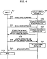
- Fig. 4 is a flow diagram illustrating the operations of one vehicle 102 and the vehicle control apparatus 101. Although the operation that the vehicle control apparatus 101 performs on one vehicle 102 will be given below for the sake of simplicity, the operation described below is, in practice, performed on each vehicle 102.
- the vehicle 102 periodically transmits vehicle state information to the vehicle control apparatus 101 (S101 and S103). Upon receiving the vehicle state information, the vehicle control apparatus 101 determines whether or not the vehicle 102 is dropped off, by using the vehicle state information (S102 and S104).
- the vehicle control apparatus 101 Upon determining that the vehicle 102 is dropped off (S104), the vehicle control apparatus 101 transmits, to the vehicle 102, an obtaining request for obtaining location information of the vehicle 102 and battery charge information of the vehicle 102 (S105). Upon receiving the obtaining request, the vehicle 102 transmits the location information and the battery charge information to the vehicle control apparatus 101 (S106).
- the vehicle control apparatus 101 determines a moving destination by using the received location information and battery charge information (S107) and transmits, to the vehicle 102, an instruction for moving the vehicle 102 to the determined moving destination (S108). Upon receiving the moving instruction, the vehicle 102 moves to the moving destination indicated by the moving instruction (S109).
- the location information and the battery charge information may be included in the vehicle state information and may be periodically transmitted to the vehicle 102.
- Fig. 5 is a flowchart illustrating the operation of the vehicle control apparatus 101.
- the vehicle information obtainer 111 obtains the vehicle state information from the vehicle 102 (S111).
- the drop-off determiner 112 determines whether or not the vehicle 102 is dropped off (S112).
- the vehicle state information includes information indicating that the button is pressed.
- the drop-off determiner 112 determines that the vehicle 102 is dropped off.
- the operation that the user performs when he or she gets out of the vehicle 102 is not limited to pressing the button.
- Such a user interface does not necessarily have to be provided in the vehicle 102, and the operation may be an input performed via a smartphone, portable terminal, or the like in the possession of the user.
- the drop-off determiner 112 may determine whether or not the vehicle 102 is dropped off, on the basis of the state of the vehicle 102 which is indicated by the vehicle state information.
- the vehicle state information may indicate the speed of the vehicle 102, and based on the speed, the drop-off determiner 112 may determine whether or not the vehicle 102 is dropped off. More specifically, when the speed of the vehicle 102 reaches zero (i.e., enters a stopped state), and this state continues for a predetermined time or more, the drop-off determiner 112 may determine that the vehicle 102 is dropped off.
- the drop-off determiner 112 may detect whether or not the user gets out of the vehicle 102 on the basis of the vehicle state information. For example, the drop-off determiner 112 may determine that the vehicle 102 is dropped off, when a door of the vehicle 102 is opened and closed and is locked after the opening and closing.
- the vehicle state information may indicate a weight that is applied to tires, a suspension, or a seat, and the drop-off determiner 112 may determine that the vehicle 102 is dropped off, when the weight changes (decreases) by a predetermined amount or more.
- the drop-off determiner 112 may determine whether or not the vehicle 102 is dropped off, on the basis of a change in the weight applied to the vehicle 102, the opening and closing of a door, or the lock of the door.
- the drop-off determiner 112 may use a combination of two or more of the above-described determination methods.
- the vehicle information obtainer 111 obtains the vehicle state information from the vehicle 102 again after a predetermined time elapses (S111), and the drop-off determiner 112 determines whether or not the vehicle 102 is dropped off, by using the obtained vehicle state information (S112).
- the moving-destination determiner 114 obtains the location of the dropped off vehicle 102, the battery charge of the vehicle 102, information about the standby places, and the demand prediction distribution (S113). Specifically, the vehicle information obtainer 111 obtains the location of the dropped off vehicle 102 and information indicating the battery charge of the vehicle 102 from the vehicle 102. Also, the information about the standby places and the demand prediction distribution are stored in the storage unit 113 as the standby-place information 121 and the demand prediction information 122.
- the moving-destination determiner 114 determines a moving destination by using obtained location of the dropped off vehicle 102, the battery charge of the vehicle 102, the information about the standby places, and the demand prediction distribution (S114). Details of this process are described later.
- the moving instructor 115 instructs the vehicle 102 to move to the determined moving destination (S115).
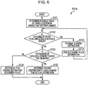
- Fig. 6 is a flowchart of this processing.
- Fig. 7 is a table illustrating one example of the standby-place information 121.
- the standby-place information 121 includes, for each standby place, a standby-place ID that is information for identifying the standby place, location information (location (x, y)) indicating the location of the standby place, and usage-state information indicating whether the standby place is in use or vacant (available).
- location information is indicated by two-dimensional coordinates, the location information may be indicated by three-dimensional coordinates or may be an address or the like.
- the standby-place manager 116 sequentially updates the usage-state information. More specifically, for example, the standby-place manager 116 periodically obtains the location information from each of the vehicles 102, and when the obtained location information matches the location information of any of the standby places, the standby-place manager 116 determines that the standby place is in use.
- the standby-place manager 116 may obtain, from each vehicle 102, information indicating that the vehicle 102 is on standby and the standby-place ID of the standby place that is currently in use and may update the usage-state information on the basis of the obtained information and standby-place ID.
- the standby-place manager 116 may obtain information indicating whether or not the standby place is in use or vacant from an apparatus installed at the standby place through a communication network or the like and may update the usage-state information on the basis of the obtained information.
- the standby-place information 121 may be map information like that illustrated in Fig. 8 .
- the moving-destination determiner 114 first determines a movable range that the vehicle 102 can travel on the current battery charge (S121).
- the moving-destination determiner 114 determines, as a movable range, a concentric circle having its center at the current location of the vehicle 102.
- the radius of the concentric circle increases in proportion to the battery charge.
- the relationship between the radius of the concentric circle and the battery charge may be pre-set or may be determined based on past traveling history of the vehicle 102. When the traveling history is used, the relationship between the radius of the concentric circle and the battery charge, the relationship differing from one vehicle 102 to another, may be set for each vehicle 102, based on the traveling history of the vehicle 102.
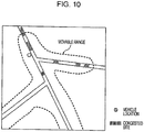
- the movable range may be determined considering a road situation or a congestion situation in addition to the battery charge.
- the congestion situation may be a congestion situation that is set for each day (each day of the week, season, or month) or for each time segment and that corresponds to the current date and time.
- the information indicating the current congestion state may be obtained from another apparatus through a communication network or the like.
- the congestion situation may be predicted from a past congestion situation.
- the congestion situation may also be predicted from moment to moment when the vehicle 102 is moving.
- the movable range is small, and since the degrees of congestion on roads in two lower and left directions are low, the movable range is large.
- the moving-destination determiner 114 determines a plurality of moving-destination candidates included in the movable range.
- the moving-destination determiner 114 determines whether or not an available standby place is included in the movable range (S122). When an available standby place is not included in the movable range (No in S122), the moving-destination determiner 114 transmits a standby instruction to the vehicle 102 via the moving instructor 115 (S123). In response to the standby instruction, the vehicle 102 stands by at the current place. Also, the moving-destination determiner 114 updates the standby-place information 121 after a predetermined time elapses (S124) and performs the process in steps S122 again by using the updated standby-place information 121. Thus, at a timing at which a standby place close to the vehicle 102 becomes vacant, an instruction for moving to the standby place is given.
- the moving-destination determiner 114 determines whether or not a plurality of available standby places is included in the movable range (S125). If a plurality of available standby places is not included in the movable range, that is, only one available standby place is included in the movable range (No in S125), the moving-destination determiner 114 determines that the moving destination is the standby place (S126).
- the moving-destination determiner 114 determines a moving destination among the moving-destination candidates that are the available standby places included in the movable range, by using the demand prediction distribution (S127).
- Fig. 11 illustrates one example of moving-destination candidates.
- Fig. 11 illustrates only available standby places among the standby places.
- three moving-destination candidates that is, standby places 1, 2, and 3, exist for vehicle A.
- Fig. 12 is a map illustrating one example of the demand prediction information 122.
- the demand prediction information 122 indicates, for example, spots where the appearance frequency of users of the vehicles 102 is high.
- the appearance frequency of users of the vehicles 102 may be set in a stepwise manner.
- the demand prediction information 122 may also be determined based on a population distribution like that illustrated in Fig. 13 . That is, the demand predictor 117 determines a demand prediction distribution on the basis of a population distribution obtained externally. Specifically, the demand predictor 117 determines that the larger the population is, the higher the demand is.
- the demand predictor 117 may also determine the population distribution or the demand prediction distribution, considering a distribution of building (e.g., planer information of buildings). For example, the demand predictor 117 may determine the population distribution or the demand prediction distribution, considering the distribution of the volumes or the floor areas of buildings. Specifically, the demand predictor 117 may determine that the larger the volume or the floor area of buildings is, the larger the population or the demand is.
- a distribution of building e.g., planer information of buildings.
- the demand predictor 117 may determine the population distribution or the demand prediction distribution, considering the distribution of the volumes or the floor areas of buildings. Specifically, the demand predictor 117 may determine that the larger the volume or the floor area of buildings is, the larger the population or the demand is.
- the demand predictor 117 may determine the population distribution or the demand prediction distribution, considering a resident map. That is, the demand predictor 117 may determine that the larger the number of residents is, the larger the population or the demand is.
- the demand predictor 117 may also determine a different demand prediction distribution at each time point. For example, the demand predictor 117 may generate a demand prediction distribution for daytime by using a daytime population map and may generate a demand prediction distribution for nighttime by using a nighttime population map.
- the demand predictor 117 may also generate a dynamic demand prediction distribution by using real-time information.
- the demand predictor 117 may generate a dynamic population distribution by using real-time information and may generate a dynamic demand prediction distribution by using the generated population distribution.
- the demand predictor 117 may determine a dynamic demand prediction distribution on the basis of dynamic (real-time) power consumption data. For example, the demand predictor 117 generates a dynamic population distribution by analyzing electric-power data of smart meters in a corresponding area. That is, the demand predictor 117 determines that the population is larger (the demand is higher) in an area where the power consumption is larger.
- the demand predictor 117 may determine a dynamic demand prediction distribution on the basis of dynamic sales data of stores. Specifically, the demand predictor 117 generates the dynamic population distribution by analyzing sales states of stores in a corresponding area. That is, the demand predictor 117 determines that the population is larger (the demand is higher) in an area where sales is higher. For example, the demand predictor 117 generates the dynamic population distribution by collecting point-of-sale (POS) data of stores and analyzing it.
- POS point-of-sale
- the demand predictor 117 may generate the demand prediction distribution by using a past usage history. Specifically, the demand predictor 117 identifies past usage-start locations on the basis of global positioning system (GPS) data of each vehicle 102 and determines that the demand is higher in an area where locations therein were used as the usage-start locations a larger number of times.
- GPS global positioning system
- the demand predictor 117 may obtain information about a tendency of getting in and out of taxis and may determine that the demand is higher in an area where the number of passengers who get in the taxis is larger.
- the demand predictor 117 may determine the dynamic demand prediction distribution on the basis of the current weather or weather forecast information. Specifically, the demand predictor 117 determines that the demand is high in a region where rain is falling or a region where rain is expected to fall from now.
- the demand predictor 117 may make the determination by combining two or more of the above-described schemes.
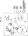
- Fig. 14 is a diagram for describing an operation when the demand prediction distribution is information indicating spots where the appearance frequency of users of the vehicles 102 is high as in the case illustrated in Fig. 12 .
- three standby places 1 to 3 exist in one movable range.
- the distances from vehicle A to standby places 1 to 3 are generally equal to each other.
- the moving-destination determiner 114 determines that the moving destination is standby place 1, which is close to spots 1 and 2 where the appearance frequency of users of the vehicles 102 is high.
- standby places in the movable range determined according to the battery charge are determined to be moving-destination candidates
- standby places included in a predetermined range may be determined to be moving-destination candidates
- the moving destination may be determined among the moving-destination candidates on the basis of the demand prediction distribution.
- the battery charge when the battery charge is greater than a predetermined threshold, the battery charge does not necessarily have to be used. Also, the battery charge does not necessarily have to be used in a particular region where there are many standby places.
- the moving-destination determiner 114 may further determine the moving destination by using the distribution of the vehicles 102.
- Fig. 15 is a table illustrating one example of the vehicle information 123. As illustrated in Fig. 15 , the vehicle information 123 indicates, for each vehicle 102, a vehicle ID for identifying the vehicle 102, the current location (location (x, y)) of the vehicle 102, the usage state of the vehicle 102, and the moving destination of the vehicle 102.
- the usage state in this case includes a state in which the vehicle 102 is stopped (available) at a standby place, a state in which the vehicle 102 is being used (in use) by a user, a state in which the vehicle 102 is moving (returning) to a standby place after drop-off, and a state in which the vehicle 102 is standing by (on standby) at the current place after drop-off. Also, when the vehicle 102 is in use, the destination thereof is set as a moving destination, and when the vehicle 102 is returning, the standby place in the vicinity of the moving destination is set as a moving destination.
- the current location and the moving destination are indicated by two-dimensional coordinates, they may be indicated by three-dimensional coordinates or may be addresses or the like.
- the standby-place ID thereof may be used.
- Fig. 16 is a flowchart of moving-destination determination processing performed by the moving-destination determiner 114 when the distribution of the vehicles 102 is used.
- the moving-destination determiner 114 determines first evaluation values for the respective moving-destination candidates on the basis of the demand prediction distribution (S131). Specifically, the moving-destination determiner 114 sets the first evaluation value higher for a standby place located in an area where the demand prediction is high or for a standby place that is close to an area where the demand prediction is high.
- the moving-destination determiner 114 sets the first evaluation value higher for a standby place located in an area where the demand level is high or a standby place that is close to an area where the demand level is high.
- the moving-destination determiner 114 determines second evaluation values for the respective moving-destination candidates on the basis of the distances from the current location to the standby places (S132). Specifically, the moving-destination determiner 114 increases the second evaluation value, as the distance from the current location to the standby place decreases. When the congestion situation or the like is considered, a time taken for the movement may be used instead of the distance. In this case, the moving-destination determiner 114 increases the second evaluation value, as the time taken for the movement gets shorter.
- the moving-destination determiner 114 determines third evaluation values for the respective moving-destination candidates on the basis of the distribution of the vehicles 102 (S133). Specifically, the moving-destination determiner 114 sets the third evaluation value lower for an area where a larger number of vehicles exist or for an area around which a larger number of vehicles exist.
- the vehicles used in the determination in this case are available vehicles (e.g., available vehicles in Fig. 15 ). Taking into account vehicles that are currently moving, the moving-destination determiner 114 may determine the third evaluation values on the basis of a vehicle distribution after a predetermined time elapses.
- the moving-destination determiner 114 determines the moving destination on the basis of the first, second, and third evaluation values (S134). For example, the moving-destination determiner 114 calculates final evaluation values by adding up the first, second, and third evaluation values for the respective moving-destination candidates and determines, as the moving destination, the moving-destination candidate with which the final evaluation value is the largest.
- the moving-destination determiner 114 independently calculates the first evaluation values and the third evaluation values, it may calculate an insufficient number of vehicles in each area on the basis of the demand prediction and the vehicle distribution and determines the evaluation values on the basis of the insufficient number of vehicles. That is, the moving-destination determiner 114 sets the evaluation value higher for a standby place that is located in an area where the number of vehicles is not sufficient or an area that is close to an area where the number of vehicles is not sufficient.
- Fig. 3 illustrates an example in which the vehicle control apparatus 101 is implemented as a single apparatus (e.g., a server) that is independent from the vehicles 102
- the functions of the vehicle control apparatus 101 may be implemented by a plurality of apparatuses that can communicate with each other.
- the standby-place manager 116, the demand predictor 117, and the vehicle information manager 118 may be provided in independent apparatuses, and the vehicle control apparatus 101 may obtain the standby-place information 121, the demand prediction information 122, and the vehicle information 123 generated by the apparatuses and store the obtained information in the storage unit 113.
- Fig. 17 is a block diagram illustrating an example in which some of the functions vehicle control apparatus 101 are provided in each vehicle 102.
- the vehicle control apparatus 101 in the vehicle 102 includes the vehicle information obtainer 111, the drop-off determiner 112, the moving-destination determiner 114, and the moving instructor 115, which are described above.
- a management apparatus 130 which is a server or the like, is provided external to the vehicle 102 and includes the storage unit 113, the standby-place manager 116, the demand predictor 117, and the vehicle information manager 118, which are described above.
- the vehicle control apparatus 101 includes a communicator 131 that communicates with the management apparatus 130.
- the communicator 131 transmits the vehicle state information and receives the standby-place information 121, the demand prediction information 122, and the vehicle information 123.
- the vehicle control apparatus 101 determines a moving destination among a plurality of standby places on the basis of the current location of the vehicle 102, the locations of the standby places, and the vehicle-demand prediction distribution. Thus, the vehicle control apparatus 101 can allocate each dropped off vehicle to an appropriate location by using the vehicle-demand prediction distribution.
- the vehicle control apparatus 101 determines the moving destination on the basis of the current battery charge of the vehicle 102.
- the vehicle control apparatus 101 can allocate the dropped off vehicle 102 to an appropriate location, taking into account the battery charge of the vehicle 102.
- the vehicle control apparatus 101 determines the moving destination on the basis of the distribution of the vehicles 102.
- the vehicle control apparatus 101 can allocate the dropped off vehicle 102 to an appropriate location, taking the distribution of the vehicles 102 into account.
- the vehicle control apparatus 101 moves the vehicle 102 in order to prepare for a next user. That is, the vehicle control apparatus 101 allocates the vehicles 102 in accordance with the distribution of users who wish to use the vehicles 102. This makes it possible to realize an environment where the vehicle 102 is always allocated to a place near a user when he or she wishes to use the vehicle 102.
- the vehicle control system 100 can also be applied to a system as described below.
- a user gives an instruction indicating his or her current location and a destination by using a tablet terminal or the like.
- the vehicle 102 which may be a community car, is sent to the user's current location.
- the vehicle 102 after use is sent to a parking place or a place where a next user called for a vehicle.
- a place to which the vehicle 102 is to be sent is determined based on the demand prediction, destination prediction, or the like, which is based on a time segment, weather forecast, a past usage situation, and so on.
- one of the vehicles 102 which is the most appropriate therefor is dispatched. Specifically, the amount of time to be taken for picking up the user, a distance that can be traveled, or the like is taken into account. Also, when the vehicle 102 returns from a destination, for example, the following possible uses are taken into account.
- the vehicle 102 may stand by or may return to a different place after the use, depending on the time segment, weather prediction after the use, or the like. For example, in the early evening, a large number of vehicles are allocated to places in the vicinity of stations or the like, and in the morning, a large number of vehicles are allocated to places in the vicinity of residential areas or the like.
- Machine learning may be used for the above-described demand prediction. For example, machine learning may be performed using, as inputs, various parameters, including time segments, weather, and so on, and history information about sites where the vehicles 102 were actually used. Since the demand varies, the machine learning may be performed so that higher priority is given to a newer parameter and newer history information.
- the power sources for the vehicles 102 are not limited to electric power and may be any known power source.
- the vehicles 102 may also be hybrid cars or the like using a plurality of power sources.
- Fig. 18 illustrates the configuration of a bicycle sharing system 200 according to the present the non-claimed aspect.
- the bicycle sharing system 200 includes a control apparatus 201, a plurality of bicycles 202, a plurality of docking stations 204, and one or more user terminals 205.
- the docking stations 204 are provided at standby places. During standby, each bicycle 202 is coupled to the docking station 204 and is locked.
- Each user terminal 205 is a terminal carried by a user 203 with him or her and is, for example, a smartphone.
- the user terminal 205 is not limited to a smartphone and may be a smart watch, a dedicated terminal, a head-mounted display, or the like.
- the user 203 installs a dedicated application to his or her user terminal 205 and registers the user terminal 205 with the bicycle sharing system 200 in advance.
- the user 203 places the user terminal 205 over a reader or the like provided on the docking station 204 or the bicycle 202, so that user authentication is performed.
- a lock is released to allow the user 203 to use the bicycle 202.
- This use method is one example, and the user authentication may be performed using an authentication card, a passcode, or the like that the user 203 is notified of in advance.
- the user 203 After using the bicycle 202, the user 203 returns the bicycle 202 by locking the bicycle 202 to any of the docking stations 204.
- the control apparatus 201 can communicate with the docking stations 204, the bicycles 202, and the user terminal 205 through a communication network or the like. The communication may be indirectly performed via another apparatus.
- the control apparatus 201 performs user management and so on as described above.
- Such a system allows a plurality of users 203 to share the plurality of bicycles 202. Also, since each user 203 does not have to return the bicycle 202 to a place where he or she rents the bicycle 202 and can return the bicycle 202 to any of the docking station 204, thus making it possible to improve the convenience of the user 203.
- Fig. 19 is a block diagram illustrating the configuration of the control apparatus 201.
- the control apparatus 201 includes a standby-place information obtainer 211, a location information obtainer 212, a storage unit 213, an incentive determiner 214, an informer 215, a standby-place manager 216, a demand predictor 217, a vehicle information obtainer 218, and a vehicle information manager 219.
- the standby-place information obtainer 211 obtains number-of-standby-bicycles information, which indicates the number of bicycles 202 on standby at standby places, from the docking stations 204.
- the storage unit 213 stores therein standby-place information 221 indicating the number of bicycles 202 that are on standby at each of the standby places, bicycle-demand prediction information 222 indicating the bicycle-demand prediction distribution, and vehicle information 223 indicating the locations, the states, and so on of the bicycles 202.
- the standby-place manager 216 manages the states of the standby places. Specifically, the standby-place manager 216 updates the standby-place information 221 by using the number-of-standby-bicycles information obtained by the standby-place information obtainer 211.
- the location information obtainer 212 obtains the current locations of the users 203 from the user terminals 205 or the bicycles 202.
- the incentive determiner 214 determines, among the standby places, recommended sites that are the standby places where incentives are to be given to the user 203 when the user 203 moves (i.e., returns the bicycle 202) to the corresponding standby places. The incentive determiner 214 also determines each incentive to be given to the user 203 when the user 203 moves to the corresponding recommended sites.
- the incentive determiner 214 determines the recommended sites and the incentives on the basis of the number of bicycles 202 on standby at the standby places and the bicycle-demand prediction information 222.
- the informer 215 informs the corresponding user 203 of the determined recommended sites and the incentives.
- the demand predictor 217 calculates the demand prediction distribution of the bicycles 202 and stores a calculation result in the storage unit 213 as the bicycle-demand prediction information 222.
- the vehicle information obtainer 218 obtains vehicle state information from the bicycles 202.
- the vehicle state information indicates, for example, the states and the locations of the respective vehicles 202.
- the vehicle information manager 219 updates the vehicle information 223.
- Fig. 20 is a flow diagram illustrating the operation of the bicycle sharing system 200.
- the docking station 204 transmits the number-of-standby-bicycles information, which indicates the number of bicycles 202 on standby at each docking station 204, to the control apparatus 201 periodically or in accordance with an instruction from the control apparatus 201 (S201).
- Fig. 20 illustrates only one docking station 204, the number-of-standby-bicycles information is transmitted from each of the docking stations 204.
- Each user terminal 205 transmits location information indicating the location of the user terminal 205 (i.e., the location of the user 203) to the control apparatus 201 periodically or in accordance with a predetermined trigger.
- the "predetermined trigger” in this case refers to an operation that the user 203 performs on the user terminal 205, placement of the user terminal 205 over the docking station 204, or the like.
- the location information is obtained, for example, from a GPS or the like provided in the user terminal 205.
- the location information does not necessarily have to be transmitted.
- the location information may also be obtained using a GPS or the like provided on the bicycle 202 or in the docking station 204.
- the control apparatus 201 determines recommended sites and respective incentives by using the received number-of-standby-bicycles information and location information (S203).
- the control apparatus 201 reports the determined recommended sites and incentives to the user terminal 205 (S204).
- the user terminal 205 informs the user 203 of the recommended sites and the incentives (S205). For example, the user terminal 205 displays the recommended sites and the incentives on a display unit of the user terminal 205.
- the control apparatus 201 may report the recommended sites and the incentives to the bicycle 202 or the docking station 204, and the bicycle 202 or the docking station 204 may inform the user 203 of the reported recommended sites and incentives.
- the bicycle 202 or the docking station 204 has a display unit and displays the recommended sites and the incentives on the display unit.
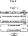
- Fig. 21 is a flowchart illustrating the operation of the control apparatus 201.
- the vehicle information obtainer 218 obtains a plurality of pieces of number-of-standby-bicycles information from the docking stations 204 (S211).
- the standby-place manager 216 calculates the current distribution of the bicycles 202 by using the pieces of number-of-standby-bicycles information and updates the standby-place information 221 (S212).
- Fig. 22 is a table illustrating one example of the standby-place information 221.
- the standby-place information 221 includes, for each of the standby places, a standby-place ID that is information for identifying the standby place, location information (location (x, y)) indicating the location of the standby place, maximum-number-of-standby-bicycles information indicating the maximum number of bicycles 202 that can stand by at the standby place, and the number-of-standby-bicycles information indicating the number of bicycles 202 that are currently on standby at the standby place.
- the location information is indicated by two-dimensional coordinates, the location information may be indicated by three-dimensional coordinates or may be an address or the like.
- the standby-place manager 216 sequentially updates the number-of-standby-bicycles information.
- the standby-place information 221 may be map information like that illustrated in Fig. 8 .
- the demand predictor 217 calculates an optimum distribution of the bicycles 202 and stores the calculated distribution in the storage unit 213 as the bicycle-demand prediction information 222 (S213).
- the calculation of the bicycle-demand prediction information 222 may be performed in advance, or demand prediction information that is externally obtained may be used as the bicycle-demand prediction information 222.
- the demand predictor 217 may also calculate the bicycle-demand prediction information 222 by using a method that is analogous to the method for determining the demand prediction information 122 used in the first embodiment. Specifically, the bicycle-demand prediction information 222 indicates the number of necessary bicycles 202 at each standby place.
- the incentive determiner 214 determines recommended sites and respective incentives by using the location information and the bicycle-demand prediction information 222 (S214). Specifically, the incentive determiner 214 determines, as recommended sites, standby places where the number of bicycles 202 on standby falls below a necessary number. When the number of standby places where the number of bicycles 202 on standby falls below the necessary number is larger than a predetermined number, the incentive determiner 214 may select the standby places corresponding to the predetermined number in descending order of the numbers of insufficient bicycles 202 relative to the necessary number or in increasing order of the ratios of the numbers of bicycles 202 on standby to the necessary number and may determine the selected predetermined number of standby places as recommended sites.
- the incentive determiner 214 may make the above-described determination on the standby places included in a predetermined range from the current location of the user 203 which is indicated by the location information.
- the incentive determiner 214 determines incentives for the respective recommended sites.
- the "incentives” as used herein refer to, for example, points given to the user 203.
- the user 203 can use the bicycle sharing system 200 by using the points, instead of cash.
- the method for using the points may be any method, and the points may be used, for example, for exchange with another service or other goods.
- Each incentive may also be a discount on a fee for the user 203 to use the bicycle sharing system 200 this time or in the future.
- the incentive determiner 214 increases the incentive as the distance from the current location of the user 203 (the bicycle 202) to the recommended site increases.
- the "distance” in this case may be a straight-line distance or a distance along a road. This makes it possible to determine each incentive corresponding to the amount of work of the user 203.
- the incentive determiner 214 may also increase the incentive as the number of bicycles 202 at each recommended site decreases relative to the demand prediction for the recommended site which is indicated by the bicycle-demand prediction information 222. That is, the incentive determiner 214 increases the incentive as the number of insufficient bicycles 202 relative to the necessary number increases or as the ratio of the number of bicycles 202 on standby to the necessary number decreases. This makes it possible to eliminate a shortage of the bicycles 202.
- the incentive determiner 214 may use the vehicle information 223 to predict the distribution of the bicycles 202 after a predetermined time elapses.
- Fig. 23 is a table illustrating one example of the vehicle information 223. As illustrated in Fig. 23 , the vehicle information 223 indicates, for each bicycle 202, a vehicle ID for identifying the bicycle 202, the current location (location (x, y)) of the bicycle 202, the state of the bicycle 202, and the moving destination of the bicycle 202.
- the vehicle information obtainer 218 updates the vehicle information 223 on the basis of information obtained from the corresponding bicycle 202, the docking stations 204, or the user terminal 205.
- the "state” in this case includes a state in which the bicycle 202 is on standby (available) at a standby place and a state in which the bicycle 202 is being used (in use) by the user 203.
- the vehicle information 223 indicates the moving destination.
- the vehicle information 223 indicates the estimated moving destination. This estimation may use a past movement history or the like.
- the incentive determiner 214 uses information about the estimated moving destination to calculate the distribution of the bicycles 202 after a predetermined time elapses and uses the calculated distribution and the bicycle-demand prediction information 222 to determine the recommended site and the incentive.
- the incentive determiner 214 may also use a past distribution to estimate the distribution of the bicycles 202 after the predetermined time elapses. For example, when the past distribution indicates that the number of bicycles 202 at a particular standby place tends to be small in a certain time segment, the incentive determiner 214 may correct the number of bicycles 202 at the particular standby place to a number smaller than the current number and then compare the corrected number with the bicycle-demand prediction information 222.
- the incentive determiner 214 may correct the number of bicycles 202 at the recommended site to a number larger than the current number and then compare the corrected number with the bicycle-demand prediction information 222.
- the informer 215 may inform the users of different recommended sites.
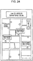
- Fig. 24 illustrates an example of a screen displayed on the user terminal 205. This screen is displayed, for example, when the user 203 comes in a predetermined range from the bicycle 202 or the docking station 204 or the user 203 places the user terminal 205 over the bicycle 202 or the docking station 204 in order to start using the bicycle 202.
- the information on the screen may be displayed on a display unit provided on the bicycle 202 or the docking station 204 or may be displayed in accordance with an operation performed by the user 203 or the like or in accordance with another trigger.
- recommended sites and the incentives (points) at the respective recommended sites are displayed on map information.
- placing a limit on the number of recommended sites that the user is informed of, as described above, makes it possible to suppress complicating information to be displayed.
- a predetermined number of recommended sites may be selected from standby places included in the range of a map that is currently displayed. That is, when the range of a map that is displayed is scrolled, or the display magnification of the map is changed, the recommended sites to be displayed may be changed.
- the user 203 moves to a recommended site with the bicycle 202 and returns the bicycle 202 at the recommended site, the corresponding incentive is given to the user 203.
- the bicycle sharing system 200 determines an incentive to be given to the user 203 when the user 203 moves the bicycle 202 to a moving destination (a recommended site) that is one of the standby places, on the basis of the number of bicycles 202 that are on standby at each of the standby places and the demand prediction information 222 of the bicycles 202, and informs the user 203 of the moving destination (the recommended site) and the incentive.
- sightseeing or the like when a user is about to sequentially visit sightseeing areas, for example, there will also be a case in which the user first visits the sightseeing area set for a recommended site.
- the scheme of the non-claimed aspect is also applicable to a system in which no standby places are provided and the bicycles 202 are dropped off at arbitrary places.
- a lock attached to the bicycle 202 is opened or closed using the user terminal 205 or the like.
- the control apparatus 201 manages the location of each bicycle 202 which is obtained using a GPS or the like provided on the bicycle 202. For example, the control apparatus 201 determines the locations of the bicycles 202 on standby on the basis of the vehicle information 223 illustrated in Fig. 23 . On the basis of the locations of the bicycles 202 on standby, the control apparatus 201 calculates the current distribution of the plurality of bicycles 202. Also, for example, meshed zones obtained by dividing a map are used instead of the standby places.
- the incentive determiner 214 determines incentives for recommended zones, which correspond to recommended sites, and incentives at the recommended zones by using the current number of bicycles 202 and the number of necessary bicycles 202 in each zone.
- the shape of the zones is not limited to a meshed shape and may be any shape.
- An object, such as a building or intersection, and surroundings thereof may be set as one zone.
- the processing units included in the vehicle control apparatus 101, the control apparatus 201, or the like according to the above-described embodiment are typically realized as large-scale integration (LSI) circuits.
- the processing units may be individually realized by single chips or at least one or all of the processing units may be realized by a single chip.
- Circuit integration is not limited to LSI and may be realized by a dedicated circuit or a general-purpose processor.
- the present disclosure may also utilize a field programmable gate array (FPGA) that can be programmed after manufacture of an LSI or a reconfigurable processor that allows reconfiguration of connections and settings of circuit cells inside an LSI.
- FPGA field programmable gate array
- the constituent elements may be implemented by dedicated hardware or may be implemented by executing a software program suitable for the constituent elements.
- a program executor such as a central processing unit (CPU) or a processor, may read and execute a software program recorded on/in a storage medium, such as a hard disk or a semiconductor memory, to thereby realize the constituent elements.
- the present disclosure may also be realized as a vehicle control method that is executed by the vehicle control apparatus.
- the present disclosure may also be realized as a bicycle sharing method or a control method that is executed by the bicycle sharing system or the control apparatus.
- each block diagram The division of the functional blocks in each block diagram is one example, and some of the functional blocks may be realized as one functional block, one of the functional blocks may be divided into a plurality of blocks, or one or more functions may be moved to another functional block.
- a single piece of hardware of software may process the functions of functional blocks having similar functions in parallel or in a time divided manner.
Landscapes
- Engineering & Computer Science (AREA)
- Physics & Mathematics (AREA)
- General Physics & Mathematics (AREA)
- Radar, Positioning & Navigation (AREA)
- Remote Sensing (AREA)
- Business, Economics & Management (AREA)
- Automation & Control Theory (AREA)
- Strategic Management (AREA)
- Human Resources & Organizations (AREA)
- Economics (AREA)
- Development Economics (AREA)
- Game Theory and Decision Science (AREA)
- Accounting & Taxation (AREA)
- General Business, Economics & Management (AREA)
- Theoretical Computer Science (AREA)
- Marketing (AREA)
- Finance (AREA)
- Entrepreneurship & Innovation (AREA)
- Artificial Intelligence (AREA)
- Operations Research (AREA)
- Quality & Reliability (AREA)
- Tourism & Hospitality (AREA)
- Health & Medical Sciences (AREA)
- Evolutionary Computation (AREA)
- Medical Informatics (AREA)
- Aviation & Aerospace Engineering (AREA)
- Mechanical Engineering (AREA)
- Traffic Control Systems (AREA)
- Electric Propulsion And Braking For Vehicles (AREA)
Description
- The present disclosure relates to a vehicle control apparatus and a vehicle control method for causing, when a vehicle that is capable of traveling autonomously Is dropped off, the vehicle to move a standby place In an unmanned manner.
- International Publication No.
2015/166811 (hereinafter referred to as "Patent Document 1") discloses a system using a self-driving vehicle (such as an electric car) that can travel autonomously. The self-driving vehicle disclosed inPatent Document 1 receives settings for an operation after a user gets out of the self-driving vehicle.Patent Document 1 also discloses that when the operation after the user gets out of the self-driving vehicle is set to "return", the self-driving vehicle returns to a predetermined return place, such as a parking lot of a nearest car rental company, after the self-driving vehicle Is dropped off.
Patent ApplicationUS 2015/0199619 A1 relates to management of reservation and parking of autonomous electrical-powered vehicles traveling along a destination route. The vehicle communicates with a management center, which sends operation instructions to the vehicle. After user reservation via an operation management center, a user is dropped off or picked up by the vehicle and the vehicle autonomously drives to large or small waiting areas to park the vehicle. The route to the waiting area (destination) is selected based on the state of the vehicle (e.g. current GPS location, remaining energy), the energy characteristics of the vehicle, energy required for traveling the route, and traveling time. The waiting areas are equipped with charging devices for recharging the vehicle. If the remaining energy is less than the travel energy, a reservation request is not possible and the user has to modify the usage settings, including a change of vehicle or content modification. Otherwise, the vehicle receives instructions commands from the management center.
Patent ApplicationUS 2016/0343068 A1 relates to automated vehicle rental and rebalancing usage of vehicle pickup/return stations. For each station, the number of available cars, an average waiting time for the vehicle at the station, an average return time for the vehicle to return to the station, the number of vehicles in a zone closest to the station, and the flow based on the average waiting and return times are calculated. These data are stored in a database. The station is added or removed from a list of departure stations or a list of arrival stations, based on determined occupancy rates (OR) and relief rates (RR). To avoid an unbalanced distribution of used and empty stations, a rebalancing of the stations is performed by selecting the vehicle movement to a station in relation to a balancing time and location.
Patent ApplicationWO 2016/147368 A1 relates to operation control of a vehicle having an automatic driving function that facilitates parking by automated searching for a parking lot using travel information of the vehicle, including position and speed of the vehicle. When a parking space not being in a prohibited parking area is found, the vehicle is parked automatically. - In such a system, it is desired that a dropped off vehicle be allocated to an appropriate location.
- One non-limiting and exemplary embodiment provides a vehicle control apparatus or a vehicle control method that can allocate a dropped of vehicle to an appropriate location.
- The present invention is defined by the features of the independent claims.
- In one general aspect, the techniques disclosed here feature an apparatus according to
claim 1. - The present disclosure can provide a vehicle control apparatus or a vehicle control method that can allocate a dropped off vehicle to an appropriate location.
- It should be noted that general or specific embodiments may be implemented as a system, a method, an integrated circuit, a computer program, a storage medium, or any selective combination thereof.
- Additional benefits and advantages of the disclosed embodiments will become apparent from the specification and drawings. The benefits and/or advantages may be individually obtained by the various embodiments and features of the specification and drawings, which need not all be provided in order to obtain one or more of such benefits and/or advantages.
-
-
Fig. 1 is a diagram illustrating the configuration of a vehicle control system according to a first embodiment; -
Fig. 2 is a view illustrating one example of a vehicle according to the first embodiment and a standby place; -
Fig. 3 is a block diagram illustrating the configuration of a vehicle control apparatus according to the first embodiment; -
Fig. 4 is a flow diagram illustrating the operations of the vehicle control system according to the first embodiment; -
Fig. 5 is a flowchart illustrating processing performed by the vehicle control apparatus according to the first embodiment; -
Fig. 6 is a flowchart illustrating moving-destination determination processing according to the first embodiment; -
Fig. 7 is a table illustrating one example of standby-place information according to the first embodiment; -
Fig. 8 illustrates one example of standby-place information according to the first embodiment; -
Fig. 9 is a map for describing movable-range determination processing according to the first embodiment; -
Fig. 10 is a map for describing the movable-range determination processing according to the first embodiment; -
Fig. 11 is a diagram illustrating one example of movable ranges according to the first embodiment; -
Fig. 12 is a map illustrating one example of demand prediction information according to the first embodiment; -
Fig. 13 is a map illustrating one example of the demand prediction information according to the first embodiment; -
Fig. 14 is a diagram for describing moving-destination determination processing according to the first embodiment; -
Fig. 15 is a table illustrating one example of vehicle information according to the first embodiment; -
Fig. 16 is a flowchart illustrating the moving-destination determination processing according to the first embodiment; -
Fig. 17 is a block diagram illustrating the configuration of a vehicle control apparatus according to a modification of the first embodiment; -
Fig. 18 illustrates the configuration of a bicycle sharing system according to a non-claimed aspect; -
Fig. 19 is a block diagram illustrating the configuration of a control apparatus according to the the non-claimed aspect; -
Fig. 20 is a flow diagram illustrating the operation of the bicycle sharing system according to the non-claimed aspect; -
Fig. 21 is a flowchart illustrating processing performed by the control apparatus according to the non-claimed aspect; -
Fig. 22 is a table illustrating one example of standby-place information according to the non-claimed aspect; -
Fig. 23 is a table illustrating one example of vehicle information according to the non-claimed aspect; -
Fig. 24 illustrates an example of a display screen according to the non-claimed aspect; and -
Fig. 25 illustrates an example of the display screen according to the non-claimed aspect. - A vehicle control apparatus according to one aspect of the present disclosure is directed to a vehicle control apparatus that causes, when a vehicle that is capable of traveling autonomously is dropped off, the vehicle to move to a standby place by traveling autonomously. The apparatus includes: a moving-destination determiner that determines, when the vehicle is dropped off, a moving destination among a plurality of standby places, based on a current location of the vehicle, locations of the standby places, and vehicle-demand prediction information; and a moving instructor that instructs the vehicle to move to the determined moving destination.
- According to this configuration, the vehicle control apparatus can allocate a dropped off vehicle to an appropriate location by using the vehicle-demand prediction information. Also, since the appropriate location can be determined in such a manner, re-moving the vehicle or the like can be suppressed or reduced, and thus the amount of fuel consumed by the vehicle can be reduced. In addition, since re-performing a computational operation, re-issuing an instruction, and so on can be suppressed, it is possible to reduce throughput of the vehicle control apparatus.
- For example, the moving-destination determiner may determine, among the standby places, moving-destination candidates included in a predetermined range from the current location and may determine the moving destination among the moving-destination candidates, based on the demand prediction information.
- For example, the vehicle may be an electrically powered vehicle; battery chargers for the vehicle is provided at the standby places; and when the vehicle is dropped off, the moving-destination determiner may determine the moving destination, based on the current location, the locations of the standby places, the demand prediction information, and a current battery charge of the vehicle.
- According to this configuration, the vehicle control apparatus can allocate a dropped off vehicle to an appropriate location, based on the battery charge of the vehicle.
- For example, the moving-destination determiner may determine, among the standby places, the moving-destination candidates included in a range that the vehicle is capable of traveling from the current location by using the current battery charge and may determine the moving destination among the moving-destination candidates, based on the demand prediction information.
- For example, when the vehicle is dropped off, the moving-destination determiner may determine, the moving destination, based on the current location, the locations of the standby places, the demand prediction information, and information about a plurality of vehicles.
- According to this configuration, the vehicle control apparatus can allocate a dropped off vehicle to an appropriate location by using the information about a plurality of vehicles.
- For example, the vehicle control apparatus may further include a demand predictor that determines the demand prediction information, based on population information.
- According to this configuration, the vehicle control apparatus can generate appropriate demand prediction information.
- For example, the vehicle control apparatus may further include a demand predictor that determines dynamic demand prediction information, based on dynamic power consumption data.
- According to this configuration, this vehicle control apparatus can generate dynamic demand prediction information based on power consumption data.
- For example, the vehicle control apparatus may further include a demand predictor that that determines the dynamic demand prediction information, based on dynamic sales data of stores.
- According to this configuration, the vehicle control apparatus can generate dynamic demand prediction information based on sales data.
- For example, the vehicle control apparatus may further include a demand predictor that determines the dynamic demand prediction information, based on weather forecast information.
- According to this configuration, the vehicle control apparatus can generate dynamic demand prediction information based on weather forecast information.
- For example, the vehicle control apparatus may further include a drop-off determiner that determines whether or not the vehicle is dropped off, based on a state of the vehicle.
- For example, the state of the vehicle may include at least one of a speed of the vehicle, a change in weight applied to the vehicle, opening and closing of a door, and locking of a door.
- According to this configuration, the vehicle control apparatus can appropriately determine drop-off of a vehicle.
- A vehicle control method according to one aspect of the present disclosure is directed to a vehicle control method that causes, when a vehicle that is capable of traveling autonomously is dropped off, the vehicle to move to a standby place by traveling autonomously. The method includes: determining, when a vehicle that is capable of traveling autonomously is dropped off, a moving destination among a plurality of standby places, based on a current location of the vehicle which is indicated by a global positioning system provided in the vehicle, locations of the standby places, and vehicle-demand prediction information; and instructing the vehicle to move to the determined moving destination.
- According to the vehicle control method, it is possible to allocate a dropped off vehicle to an appropriate location by using the vehicle-demand prediction information.
- The configuration for allocating a vehicle to an appropriate location by using the vehicle-demand prediction information can also be applied to a bicycle sharing system.
- The bicycle sharing system includes: an incentive determiner that determines an incentive to be given to a user when the user moves a bicycle to a moving destination that is one of standby places, based on the number of bicycles on standby at each of the standby places and bicycle-demand prediction information, and an informer that informs the user of the moving destination and the incentive.
- According to this configuration, by using the vehicle (i.e., bicycle) demand prediction information, the bicycle sharing system can guide users so that vehicles are allocated to appropriate locations. Since the appropriate locations can be determined in such a manner, it is possible to suppress re-performing a computational operation, re-issuing an instruction, and so on, thus making it possible to reduce throughput of a control apparatus.
- The incentive determiner may increase the incentive, as the distance from the current location of the bicycle to the moving destination increases.
- According to this configuration, the bicycle sharing system can determine an appropriate incentive.
- The incentive determiner may increase the incentive, as the number of bicycles that are present at the moving destination gets smaller relative to demand prediction for the moving destination, the demand prediction being indicated by the demand prediction information.
- According to this configuration, the bicycle sharing system can guide users so that the vehicles are allocated to more appropriate locations.
- A bicycle sharing system may include: determining an incentive to be given to a user when the user moves a bicycle to a moving destination that is one of standby places, based on the number of bicycles on standby at each of the standby places and bicycle-demand prediction information, and informing the user of the moving destination and the incentive.
- According to the bicycle sharing method, by using the vehicle (i.e., bicycle) demand prediction information, it is possible to guide users so that the vehicles are allocated to appropriate locations.
- It should be noted that general or specific embodiments may be implemented as a system, a method, an integrated circuit, a computer program, a computer-readable storage medium such as compact disc read-only memory (CD-ROM), or any selective combination thereof.
- Embodiments will be described below in detail with reference to the accompanying drawings. The embodiments described below each represent a general or specific example. Numerical values, shapes, materials, constituent elements, the arrangement positions and connections of constituent elements, steps, the order of steps, and so on described in the embodiments below are examples and are not intended to limit the present disclosure. Of the constituent elements in the embodiments described below, the constituent elements not set forth in the independent claims that represent the broadest concept will be described as optional constituent elements.
- First, a description will be given of the configuration of a vehicle control system according to a first embodiment.
Fig. 1 is a diagram illustrating the configuration of avehicle control system 100 according to the first embodiment. As illustrated inFig. 1 , thevehicle control system 100 includes a plurality ofvehicles 102 and avehicle control apparatus 101 that controls thevehicles 102. - Each of the
vehicles 102 is, for example, an electrically powered vehicle, such as an electric vehicle, having an autonomous driving function and can travel autonomously (e.g., in an unmanned manner). - For example, as illustrated in
Fig. 2 , eachvehicle 102 can be parked or charged in small space in a town. Thus, users can use thevehicles 102 parked at various standby places in the town. For example, each user rides one of thevehicles 102 that are parked and sets a destination. Thus, thevehicle 102 travels autonomously to the set destination while the user is in thevehicle 102. The user may pre-set the destination via a portable terminal or the like, before he or she gets in thevehicle 102. When the user gets out of thevehicle 102 at the destination, thevehicle 102 travels autonomously to one of the standby places, stands by, and performs charging. A user getting out of thevehicle 102 at a destination is herein referred to as "drop off". - When a user is in the
vehicle 102, thevehicle 102 may be driven by the user, rather than traveling autonomously. - Also, instead of a user visiting one of the standby places, the
vehicle 102 may move to a pickup place designated by the user by traveling autonomously, on the basis of the user's instruction given or reservation made via a portable terminal or the like. In this case, thevehicle 102 may move, by traveling autonomously, thevehicle 102 closest to a pickup place designated by the user to the pickup place by. Also, thevehicle 102 that moves to the pickup place may be determined based on a destination set by the user, rather than moving thevehicle 102 closest to the pickup place designated by the user. For example, when thevehicle 102 that is being sent toward a place in the vicinity of a destination set by the user is moved to a pickup place by traveling autonomously, it is possible to realize efficient vehicle dispatch. - Each of the standby places is not limited to a private parking space like that illustrated in
Fig. 2 and may be a parking space where a business operator runs a parking-lot business, a public parking space, or the like. In this case, battery chargers for thevehicles 102 are provided at the standby places. For example, eachvehicle 102 is automatically charged by a method in which a charging connector is physically connected thereto or by a method using contactless charging. Work for the charging may be partly or entirely performed by personnel who are present at each standby place. - The
vehicle control apparatus 101 can communicate with thevehicles 102 through a communication network or the like. When one of thevehicles 102 is dropped off, thevehicle control apparatus 101 causes thevehicle 102 to move to a standby place by traveling autonomously (e.g., in an unmanned manner). - Next, a description will be given of the configuration of the
vehicle control apparatus 101.Fig. 3 is a block diagram illustrating the configuration of thevehicle control apparatus 101. As illustrated inFig. 3 , thevehicle control apparatus 101 includes avehicle information obtainer 111, a drop-off determiner 112, astorage unit 113, a moving-destination determiner 114, a movinginstructor 115, a standby-place manager 116, ademand predictor 117, and avehicle information manager 118. - The
vehicle information obtainer 111 obtains vehicle state information from eachvehicle 102. The vehicle state information indicates, for example, the state and the location of eachvehicle 102. - On the basis of the state of the
vehicle 102 which is indicated by the vehicle state information obtained from thevehicle 102, the drop-off determiner 112 determines whether or not thevehicle 102 is dropped off. - The
storage unit 113 stores therein standby-place information 121 indicating the locations of standby places,demand prediction information 122 indicating vehicle-demand prediction distribution, andvehicle information 123 indicating the states and the distribution (locations) of thevehicles 102. - When one of the
vehicles 102 is dropped off, the moving-destination determiner 114 determines a moving destination of thevehicle 102 among the standby places indicated by the standby-place information 121. More specifically, the moving-destination determiner 114 determines a moving destination among the plurality of standby places on the basis of the current location of thevehicle 102, the locations of the standby places indicated by the standby-place information 121, the vehicle-demand prediction distribution indicated by thedemand prediction information 122, and the distribution of the vehicles indicated by thevehicle information 123. - The moving
instructor 115 instructs thevehicle 102 to move to the determined moving destination. - The standby-
place manager 116 manages the standby places. For example, the standby-place manager 116 periodically obtains, from thevehicles 102, information indicating at which of the standby places thevehicle 102 is on standby or periodically obtains, from each standby place, information indicating whether or not the standby place is vacant and manages whether or not each standby place is vacant on the basis of the obtained information. - The
demand predictor 117 determines the vehicle-demand prediction distribution and stores a determination result in thestorage unit 113 as thedemand prediction information 122. - The
vehicle information manager 118 updates thevehicle information 123 on the basis of the vehicle state information of thevehicles 102 which is obtained from thevehicles 102. - Next, a description will be given of the operation of the
vehicle control apparatus 101.Fig. 4 is a flow diagram illustrating the operations of onevehicle 102 and thevehicle control apparatus 101. Although the operation that thevehicle control apparatus 101 performs on onevehicle 102 will be given below for the sake of simplicity, the operation described below is, in practice, performed on eachvehicle 102. - As illustrated in
Fig. 4 , thevehicle 102 periodically transmits vehicle state information to the vehicle control apparatus 101 (S101 and S103). Upon receiving the vehicle state information, thevehicle control apparatus 101 determines whether or not thevehicle 102 is dropped off, by using the vehicle state information (S102 and S104). - Upon determining that the
vehicle 102 is dropped off (S104), thevehicle control apparatus 101 transmits, to thevehicle 102, an obtaining request for obtaining location information of thevehicle 102 and battery charge information of the vehicle 102 (S105). Upon receiving the obtaining request, thevehicle 102 transmits the location information and the battery charge information to the vehicle control apparatus 101 (S106). - Next, the
vehicle control apparatus 101 determines a moving destination by using the received location information and battery charge information (S107) and transmits, to thevehicle 102, an instruction for moving thevehicle 102 to the determined moving destination (S108). Upon receiving the moving instruction, thevehicle 102 moves to the moving destination indicated by the moving instruction (S109). - In this case, although an example in which the location information and the battery charge information are obtained when it is determined that the
vehicle 102 is dropped off is described, the location information and the battery charge information may be included in the vehicle state information and may be periodically transmitted to thevehicle 102. -
Fig. 5 is a flowchart illustrating the operation of thevehicle control apparatus 101. First, thevehicle information obtainer 111 obtains the vehicle state information from the vehicle 102 (S111). - Next, by using the obtained vehicle state information, the drop-
off determiner 112 determines whether or not thevehicle 102 is dropped off (S112). - Specifically, for example, when the user gets out of the
vehicle 102, he or she presses a button provided therein. The vehicle state information includes information indicating that the button is pressed. When the vehicle state information includes the information indicating that the button is pressed, the drop-off determiner 112 determines that thevehicle 102 is dropped off. The operation that the user performs when he or she gets out of thevehicle 102 is not limited to pressing the button. Such a user interface does not necessarily have to be provided in thevehicle 102, and the operation may be an input performed via a smartphone, portable terminal, or the like in the possession of the user. - Alternatively, the drop-
off determiner 112 may determine whether or not thevehicle 102 is dropped off, on the basis of the state of thevehicle 102 which is indicated by the vehicle state information. For example, the vehicle state information may indicate the speed of thevehicle 102, and based on the speed, the drop-off determiner 112 may determine whether or not thevehicle 102 is dropped off. More specifically, when the speed of thevehicle 102 reaches zero (i.e., enters a stopped state), and this state continues for a predetermined time or more, the drop-off determiner 112 may determine that thevehicle 102 is dropped off. - Alternatively, the drop-
off determiner 112 may detect whether or not the user gets out of thevehicle 102 on the basis of the vehicle state information. For example, the drop-off determiner 112 may determine that thevehicle 102 is dropped off, when a door of thevehicle 102 is opened and closed and is locked after the opening and closing. Alternatively, the vehicle state information may indicate a weight that is applied to tires, a suspension, or a seat, and the drop-off determiner 112 may determine that thevehicle 102 is dropped off, when the weight changes (decreases) by a predetermined amount or more. As described above, the drop-off determiner 112 may determine whether or not thevehicle 102 is dropped off, on the basis of a change in the weight applied to thevehicle 102, the opening and closing of a door, or the lock of the door. The drop-off determiner 112 may use a combination of two or more of the above-described determination methods. - If it is determined that the
vehicle 102 is not dropped off (No in S112), thevehicle information obtainer 111 obtains the vehicle state information from thevehicle 102 again after a predetermined time elapses (S111), and the drop-off determiner 112 determines whether or not thevehicle 102 is dropped off, by using the obtained vehicle state information (S112). - On the other hand, if it is determined that the
vehicle 102 is dropped off (Yes in S112), the moving-destination determiner 114 obtains the location of the dropped offvehicle 102, the battery charge of thevehicle 102, information about the standby places, and the demand prediction distribution (S113). Specifically, thevehicle information obtainer 111 obtains the location of the dropped offvehicle 102 and information indicating the battery charge of thevehicle 102 from thevehicle 102. Also, the information about the standby places and the demand prediction distribution are stored in thestorage unit 113 as the standby-place information 121 and thedemand prediction information 122. - Next, the moving-
destination determiner 114 determines a moving destination by using obtained location of the dropped offvehicle 102, the battery charge of thevehicle 102, the information about the standby places, and the demand prediction distribution (S114). Details of this process are described later. - Lastly, the moving
instructor 115 instructs thevehicle 102 to move to the determined moving destination (S115). - Next, a description will be given of details of the moving-destination determination processing (S114) performed by the moving-
destination determiner 114. First, a description will be given of moving-destination determination processing using a demand prediction distribution and a battery charge.Fig. 6 is a flowchart of this processing.Fig. 7 is a table illustrating one example of the standby-place information 121. - As illustrated in
Fig. 7 , the standby-place information 121 includes, for each standby place, a standby-place ID that is information for identifying the standby place, location information (location (x, y)) indicating the location of the standby place, and usage-state information indicating whether the standby place is in use or vacant (available). Although the location information is indicated by two-dimensional coordinates, the location information may be indicated by three-dimensional coordinates or may be an address or the like. - Also, the standby-
place manager 116 sequentially updates the usage-state information. More specifically, for example, the standby-place manager 116 periodically obtains the location information from each of thevehicles 102, and when the obtained location information matches the location information of any of the standby places, the standby-place manager 116 determines that the standby place is in use. The standby-place manager 116 may obtain, from eachvehicle 102, information indicating that thevehicle 102 is on standby and the standby-place ID of the standby place that is currently in use and may update the usage-state information on the basis of the obtained information and standby-place ID. Alternatively, the standby-place manager 116 may obtain information indicating whether or not the standby place is in use or vacant from an apparatus installed at the standby place through a communication network or the like and may update the usage-state information on the basis of the obtained information. - Also, the standby-
place information 121 may be map information like that illustrated inFig. 8 . - As illustrated in
Fig. 6 , by using the current location of thevehicle 102 when it is dropped off and the current battery charge of thevehicle 102 when it is dropped off, the moving-destination determiner 114 first determines a movable range that thevehicle 102 can travel on the current battery charge (S121). - For example, as illustrated in
Fig. 9 , the moving-destination determiner 114 determines, as a movable range, a concentric circle having its center at the current location of thevehicle 102. The radius of the concentric circle increases in proportion to the battery charge. The relationship between the radius of the concentric circle and the battery charge may be pre-set or may be determined based on past traveling history of thevehicle 102. When the traveling history is used, the relationship between the radius of the concentric circle and the battery charge, the relationship differing from onevehicle 102 to another, may be set for eachvehicle 102, based on the traveling history of thevehicle 102. - Alternatively, as illustrated in
Fig. 10 , the movable range may be determined considering a road situation or a congestion situation in addition to the battery charge. The congestion situation may be a congestion situation that is set for each day (each day of the week, season, or month) or for each time segment and that corresponds to the current date and time. Also, the information indicating the current congestion state may be obtained from another apparatus through a communication network or the like. The congestion situation may be predicted from a past congestion situation. The congestion situation may also be predicted from moment to moment when thevehicle 102 is moving. - For example, in the example illustrated in
Fig. 10 , since the degrees of congestion on roads in two upper and right directions are high, the movable range is small, and since the degrees of congestion on roads in two lower and left directions are low, the movable range is large. - Next, the moving-
destination determiner 114 determines a plurality of moving-destination candidates included in the movable range. First, the moving-destination determiner 114 determines whether or not an available standby place is included in the movable range (S122). When an available standby place is not included in the movable range (No in S122), the moving-destination determiner 114 transmits a standby instruction to thevehicle 102 via the moving instructor 115 (S123). In response to the standby instruction, thevehicle 102 stands by at the current place. Also, the moving-destination determiner 114 updates the standby-place information 121 after a predetermined time elapses (S124) and performs the process in steps S122 again by using the updated standby-place information 121. Thus, at a timing at which a standby place close to thevehicle 102 becomes vacant, an instruction for moving to the standby place is given. - On the other hand, if an available standby place is included in the movable range (Yes in S122), the moving-
destination determiner 114 determines whether or not a plurality of available standby places is included in the movable range (S125). If a plurality of available standby places is not included in the movable range, that is, only one available standby place is included in the movable range (No in S125), the moving-destination determiner 114 determines that the moving destination is the standby place (S126). - On the other hand, if a plurality of available standby places is included in the movable range (Yes in S125), the moving-
destination determiner 114 determines a moving destination among the moving-destination candidates that are the available standby places included in the movable range, by using the demand prediction distribution (S127). -
Fig. 11 illustrates one example of moving-destination candidates.Fig. 11 illustrates only available standby places among the standby places. In this example, three moving-destination candidates, that is, standby places 1, 2, and 3, exist for vehicle A. -
Fig. 12 is a map illustrating one example of thedemand prediction information 122. As illustrated inFig. 12 , thedemand prediction information 122 indicates, for example, spots where the appearance frequency of users of thevehicles 102 is high. The appearance frequency of users of thevehicles 102 may be set in a stepwise manner. - The
demand prediction information 122 may also be determined based on a population distribution like that illustrated inFig. 13 . That is, thedemand predictor 117 determines a demand prediction distribution on the basis of a population distribution obtained externally. Specifically, thedemand predictor 117 determines that the larger the population is, the higher the demand is. - The
demand predictor 117 may also determine the population distribution or the demand prediction distribution, considering a distribution of building (e.g., planer information of buildings). For example, thedemand predictor 117 may determine the population distribution or the demand prediction distribution, considering the distribution of the volumes or the floor areas of buildings. Specifically, thedemand predictor 117 may determine that the larger the volume or the floor area of buildings is, the larger the population or the demand is. - Also, the
demand predictor 117 may determine the population distribution or the demand prediction distribution, considering a resident map. That is, thedemand predictor 117 may determine that the larger the number of residents is, the larger the population or the demand is. - The
demand predictor 117 may also determine a different demand prediction distribution at each time point. For example, thedemand predictor 117 may generate a demand prediction distribution for daytime by using a daytime population map and may generate a demand prediction distribution for nighttime by using a nighttime population map. - The
demand predictor 117 may also generate a dynamic demand prediction distribution by using real-time information. For example, thedemand predictor 117 may generate a dynamic population distribution by using real-time information and may generate a dynamic demand prediction distribution by using the generated population distribution. - For example, the
demand predictor 117 may determine a dynamic demand prediction distribution on the basis of dynamic (real-time) power consumption data. For example, thedemand predictor 117 generates a dynamic population distribution by analyzing electric-power data of smart meters in a corresponding area. That is, thedemand predictor 117 determines that the population is larger (the demand is higher) in an area where the power consumption is larger. - Alternatively, the
demand predictor 117 may determine a dynamic demand prediction distribution on the basis of dynamic sales data of stores. Specifically, thedemand predictor 117 generates the dynamic population distribution by analyzing sales states of stores in a corresponding area. That is, thedemand predictor 117 determines that the population is larger (the demand is higher) in an area where sales is higher. For example, thedemand predictor 117 generates the dynamic population distribution by collecting point-of-sale (POS) data of stores and analyzing it. - Alternatively, the
demand predictor 117 may generate the demand prediction distribution by using a past usage history. Specifically, thedemand predictor 117 identifies past usage-start locations on the basis of global positioning system (GPS) data of eachvehicle 102 and determines that the demand is higher in an area where locations therein were used as the usage-start locations a larger number of times. - Alternatively, the
demand predictor 117 may obtain information about a tendency of getting in and out of taxis and may determine that the demand is higher in an area where the number of passengers who get in the taxis is larger. - Alternatively, the
demand predictor 117 may determine the dynamic demand prediction distribution on the basis of the current weather or weather forecast information. Specifically, thedemand predictor 117 determines that the demand is high in a region where rain is falling or a region where rain is expected to fall from now. - The
demand predictor 117 may make the determination by combining two or more of the above-described schemes. -
Fig. 14 is a diagram for describing an operation when the demand prediction distribution is information indicating spots where the appearance frequency of users of thevehicles 102 is high as in the case illustrated inFig. 12 . In the example illustrated inFig. 14 , threestandby places 1 to 3 exist in one movable range. Also, the distances from vehicle A tostandby places 1 to 3 are generally equal to each other. In this case, the moving-destination determiner 114 determines that the moving destination isstandby place 1, which is close tospots vehicles 102 is high. - Although an example in which the standby places in the movable range determined according to the battery charge are determined to be moving-destination candidates, standby places included in a predetermined range may be determined to be moving-destination candidates, and the moving destination may be determined among the moving-destination candidates on the basis of the demand prediction distribution.
- For example, when the battery charge is greater than a predetermined threshold, the battery charge does not necessarily have to be used. Also, the battery charge does not necessarily have to be used in a particular region where there are many standby places.
- The moving-
destination determiner 114 may further determine the moving destination by using the distribution of thevehicles 102.Fig. 15 is a table illustrating one example of thevehicle information 123. As illustrated inFig. 15 , thevehicle information 123 indicates, for eachvehicle 102, a vehicle ID for identifying thevehicle 102, the current location (location (x, y)) of thevehicle 102, the usage state of thevehicle 102, and the moving destination of thevehicle 102. - The usage state in this case includes a state in which the
vehicle 102 is stopped (available) at a standby place, a state in which thevehicle 102 is being used (in use) by a user, a state in which thevehicle 102 is moving (returning) to a standby place after drop-off, and a state in which thevehicle 102 is standing by (on standby) at the current place after drop-off. Also, when thevehicle 102 is in use, the destination thereof is set as a moving destination, and when thevehicle 102 is returning, the standby place in the vicinity of the moving destination is set as a moving destination. - These pieces of information are periodically transmitted from the
vehicles 102 to thevehicle control apparatus 101. Although the current location and the moving destination are indicated by two-dimensional coordinates, they may be indicated by three-dimensional coordinates or may be addresses or the like. When the current location or the moving destination matches any of the standby place, the standby-place ID thereof may be used. -
Fig. 16 is a flowchart of moving-destination determination processing performed by the moving-destination determiner 114 when the distribution of thevehicles 102 is used. First, the moving-destination determiner 114 determines first evaluation values for the respective moving-destination candidates on the basis of the demand prediction distribution (S131). Specifically, the moving-destination determiner 114 sets the first evaluation value higher for a standby place located in an area where the demand prediction is high or for a standby place that is close to an area where the demand prediction is high. When the demand prediction indicates a demand level, the moving-destination determiner 114 sets the first evaluation value higher for a standby place located in an area where the demand level is high or a standby place that is close to an area where the demand level is high. - Next, the moving-
destination determiner 114 determines second evaluation values for the respective moving-destination candidates on the basis of the distances from the current location to the standby places (S132). Specifically, the moving-destination determiner 114 increases the second evaluation value, as the distance from the current location to the standby place decreases. When the congestion situation or the like is considered, a time taken for the movement may be used instead of the distance. In this case, the moving-destination determiner 114 increases the second evaluation value, as the time taken for the movement gets shorter. - Next, the moving-
destination determiner 114 determines third evaluation values for the respective moving-destination candidates on the basis of the distribution of the vehicles 102 (S133). Specifically, the moving-destination determiner 114 sets the third evaluation value lower for an area where a larger number of vehicles exist or for an area around which a larger number of vehicles exist. The vehicles used in the determination in this case are available vehicles (e.g., available vehicles inFig. 15 ). Taking into account vehicles that are currently moving, the moving-destination determiner 114 may determine the third evaluation values on the basis of a vehicle distribution after a predetermined time elapses. - Lastly, the moving-
destination determiner 114 determines the moving destination on the basis of the first, second, and third evaluation values (S134). For example, the moving-destination determiner 114 calculates final evaluation values by adding up the first, second, and third evaluation values for the respective moving-destination candidates and determines, as the moving destination, the moving-destination candidate with which the final evaluation value is the largest. - Although, in the above description, the moving-
destination determiner 114 independently calculates the first evaluation values and the third evaluation values, it may calculate an insufficient number of vehicles in each area on the basis of the demand prediction and the vehicle distribution and determines the evaluation values on the basis of the insufficient number of vehicles. That is, the moving-destination determiner 114 sets the evaluation value higher for a standby place that is located in an area where the number of vehicles is not sufficient or an area that is close to an area where the number of vehicles is not sufficient. - In addition, although
Fig. 3 illustrates an example in which thevehicle control apparatus 101 is implemented as a single apparatus (e.g., a server) that is independent from thevehicles 102, the functions of thevehicle control apparatus 101 may be implemented by a plurality of apparatuses that can communicate with each other. For example, the standby-place manager 116, thedemand predictor 117, and thevehicle information manager 118 may be provided in independent apparatuses, and thevehicle control apparatus 101 may obtain the standby-place information 121, thedemand prediction information 122, and thevehicle information 123 generated by the apparatuses and store the obtained information in thestorage unit 113. - Also, some of the functions of the
vehicle control apparatus 101 may be provided in eachvehicle 102.Fig. 17 is a block diagram illustrating an example in which some of the functionsvehicle control apparatus 101 are provided in eachvehicle 102. In the example illustrated inFig. 17 , thevehicle control apparatus 101 in thevehicle 102 includes thevehicle information obtainer 111, the drop-off determiner 112, the moving-destination determiner 114, and the movinginstructor 115, which are described above. Also, amanagement apparatus 130, which is a server or the like, is provided external to thevehicle 102 and includes thestorage unit 113, the standby-place manager 116, thedemand predictor 117, and thevehicle information manager 118, which are described above. - The
vehicle control apparatus 101 includes acommunicator 131 that communicates with themanagement apparatus 130. Thecommunicator 131 transmits the vehicle state information and receives the standby-place information 121, thedemand prediction information 122, and thevehicle information 123. - As described above, when the
vehicle 102 is dropped off, thevehicle control apparatus 101 according to the present embodiment determines a moving destination among a plurality of standby places on the basis of the current location of thevehicle 102, the locations of the standby places, and the vehicle-demand prediction distribution. Thus, thevehicle control apparatus 101 can allocate each dropped off vehicle to an appropriate location by using the vehicle-demand prediction distribution. - In addition, when one
vehicle 102 is dropped off, thevehicle control apparatus 101 determines the moving destination on the basis of the current battery charge of thevehicle 102. Thus, thevehicle control apparatus 101 can allocate the dropped offvehicle 102 to an appropriate location, taking into account the battery charge of thevehicle 102. - In addition, when the
vehicle 102 is dropped off, thevehicle control apparatus 101 determines the moving destination on the basis of the distribution of thevehicles 102. Thus, thevehicle control apparatus 101 can allocate the dropped offvehicle 102 to an appropriate location, taking the distribution of thevehicles 102 into account. - There are also cases in which, when the
vehicle 102 is dropped off, the distribution of thevehicles 102 is unbalanced and differs from an allocation corresponding to the distribution of users who wish to use thevehicles 102. In this case, there are cases in which novehicle 102 is allocated to a place near a user who wishes to use thevehicle 102, and thus the user cannot use thevehicle 102. - As described above, after one user finishes using one of the
vehicles 102, thevehicle control apparatus 101 according to the present embodiment moves thevehicle 102 in order to prepare for a next user. That is, thevehicle control apparatus 101 allocates thevehicles 102 in accordance with the distribution of users who wish to use thevehicles 102. This makes it possible to realize an environment where thevehicle 102 is always allocated to a place near a user when he or she wishes to use thevehicle 102. - The
vehicle control system 100 can also be applied to a system as described below. - First, a user gives an instruction indicating his or her current location and a destination by using a tablet terminal or the like. On the basis of the conditions indicated by the instruction, the
vehicle 102, which may be a community car, is sent to the user's current location. - After the user finishes using the
vehicle 102, when he or she presses an "end" button provided in thevehicle 102 or the like, a usage fee is settled with credit. - In accordance with an instruction from a central office, the
vehicle 102 after use is sent to a parking place or a place where a next user called for a vehicle. - A place to which the
vehicle 102 is to be sent is determined based on the demand prediction, destination prediction, or the like, which is based on a time segment, weather forecast, a past usage situation, and so on. - When a reservation for using one of the
vehicles 102 is made, one of thevehicles 102 which is the most appropriate therefor is dispatched. Specifically, the amount of time to be taken for picking up the user, a distance that can be traveled, or the like is taken into account. Also, when thevehicle 102 returns from a destination, for example, the following possible uses are taken into account. - For example, even when the
vehicle 102 is used from the same site to the same destination, thevehicle 102 may stand by or may return to a different place after the use, depending on the time segment, weather prediction after the use, or the like. For example, in the early evening, a large number of vehicles are allocated to places in the vicinity of stations or the like, and in the morning, a large number of vehicles are allocated to places in the vicinity of residential areas or the like. - When a reservation for using the
vehicle 102 is made when it is traveling to a place to which it should return, or when a request for using the vehicle is received when the vehicle is traveling on a schedule route, a route is changed upon approval by the central office. - Machine learning may be used for the above-described demand prediction. For example, machine learning may be performed using, as inputs, various parameters, including time segments, weather, and so on, and history information about sites where the
vehicles 102 were actually used. Since the demand varies, the machine learning may be performed so that higher priority is given to a newer parameter and newer history information. - Although the above description has been given of the
vehicle control apparatus 101 and thevehicle control system 100 according to the present embodiment, the present disclosure is not limited to the embodiment. - For example, although an example in which people are transported has been described above, the scheme of the present embodiment is also applicable to cases in which objects are transported.
- In addition, although the above description has been given of an example of a case in which the
vehicles 102 are electrically powered vehicles, the power sources for thevehicles 102 are not limited to electric power and may be any known power source. Thevehicles 102 may also be hybrid cars or the like using a plurality of power sources. - In a non-claimed aspect, a description will be given of a bicycle sharing system that can reduce an imbalance in the distribution of bicycles.
- First, a description will be given of the configuration of a bicycle sharing system according to the the non-claimed aspect.
Fig. 18 illustrates the configuration of abicycle sharing system 200 according to the present the non-claimed aspect. As illustrated inFig. 18 , thebicycle sharing system 200 includes acontrol apparatus 201, a plurality ofbicycles 202, a plurality ofdocking stations 204, and one ormore user terminals 205. - The
docking stations 204 are provided at standby places. During standby, eachbicycle 202 is coupled to thedocking station 204 and is locked. - Each
user terminal 205 is a terminal carried by auser 203 with him or her and is, for example, a smartphone. Theuser terminal 205 is not limited to a smartphone and may be a smart watch, a dedicated terminal, a head-mounted display, or the like. - For example, the
user 203 installs a dedicated application to his or heruser terminal 205 and registers theuser terminal 205 with thebicycle sharing system 200 in advance. Next, at any of thedocking stations 204, theuser 203 places theuser terminal 205 over a reader or the like provided on thedocking station 204 or thebicycle 202, so that user authentication is performed. As a result, a lock is released to allow theuser 203 to use thebicycle 202. This use method is one example, and the user authentication may be performed using an authentication card, a passcode, or the like that theuser 203 is notified of in advance. - Also, after using the
bicycle 202, theuser 203 returns thebicycle 202 by locking thebicycle 202 to any of thedocking stations 204. - The
control apparatus 201 can communicate with thedocking stations 204, thebicycles 202, and theuser terminal 205 through a communication network or the like. The communication may be indirectly performed via another apparatus. Thecontrol apparatus 201 performs user management and so on as described above. - Such a system allows a plurality of
users 203 to share the plurality ofbicycles 202. Also, since eachuser 203 does not have to return thebicycle 202 to a place where he or she rents thebicycle 202 and can return thebicycle 202 to any of thedocking station 204, thus making it possible to improve the convenience of theuser 203. - Meanwhile, since each
user 203 can return thebicycle 202 to any of thedocking stations 204, a problem that the distribution of thebicycles 202 becomes unbalance occurs. Consequently, cases in which nobicycle 202 remains at a place where any of theusers 203 wishes to rent thebicycle 202 occur, thus reducing the convenience of theusers 203. In addition, a problem that the cost for moving thebicycles 202 is required arises. In the present non-claimed aspect, a description will be given of a scheme that can reduce such an imbalance in the distribution of thebicycles 202. -
Fig. 19 is a block diagram illustrating the configuration of thecontrol apparatus 201. As illustrated inFig. 19 , thecontrol apparatus 201 includes a standby-place information obtainer 211, alocation information obtainer 212, astorage unit 213, anincentive determiner 214, aninformer 215, a standby-place manager 216, ademand predictor 217, avehicle information obtainer 218, and avehicle information manager 219. - The standby-
place information obtainer 211 obtains number-of-standby-bicycles information, which indicates the number ofbicycles 202 on standby at standby places, from thedocking stations 204. - The
storage unit 213 stores therein standby-place information 221 indicating the number ofbicycles 202 that are on standby at each of the standby places, bicycle-demand prediction information 222 indicating the bicycle-demand prediction distribution, andvehicle information 223 indicating the locations, the states, and so on of thebicycles 202. - The standby-
place manager 216 manages the states of the standby places. Specifically, the standby-place manager 216 updates the standby-place information 221 by using the number-of-standby-bicycles information obtained by the standby-place information obtainer 211. - The
location information obtainer 212 obtains the current locations of theusers 203 from theuser terminals 205 or thebicycles 202. - The
incentive determiner 214 determines, among the standby places, recommended sites that are the standby places where incentives are to be given to theuser 203 when theuser 203 moves (i.e., returns the bicycle 202) to the corresponding standby places. Theincentive determiner 214 also determines each incentive to be given to theuser 203 when theuser 203 moves to the corresponding recommended sites. - More specifically, the
incentive determiner 214 determines the recommended sites and the incentives on the basis of the number ofbicycles 202 on standby at the standby places and the bicycle-demand prediction information 222. - The
informer 215 informs thecorresponding user 203 of the determined recommended sites and the incentives. - The
demand predictor 217 calculates the demand prediction distribution of thebicycles 202 and stores a calculation result in thestorage unit 213 as the bicycle-demand prediction information 222. - The
vehicle information obtainer 218 obtains vehicle state information from thebicycles 202. The vehicle state information indicates, for example, the states and the locations of therespective vehicles 202. - On the basis of the vehicle state information obtained from the
bicycles 202, thevehicle information manager 219 updates thevehicle information 223. - Next, a description will be given of the operation of the
bicycle sharing system 200.Fig. 20 is a flow diagram illustrating the operation of thebicycle sharing system 200. - As illustrated in
Fig. 20 , thedocking station 204 transmits the number-of-standby-bicycles information, which indicates the number ofbicycles 202 on standby at eachdocking station 204, to thecontrol apparatus 201 periodically or in accordance with an instruction from the control apparatus 201 (S201). AlthoughFig. 20 illustrates only onedocking station 204, the number-of-standby-bicycles information is transmitted from each of thedocking stations 204. - Each
user terminal 205 transmits location information indicating the location of the user terminal 205 (i.e., the location of the user 203) to thecontrol apparatus 201 periodically or in accordance with a predetermined trigger. The "predetermined trigger" in this case refers to an operation that theuser 203 performs on theuser terminal 205, placement of theuser terminal 205 over thedocking station 204, or the like. The location information is obtained, for example, from a GPS or the like provided in theuser terminal 205. - The location information does not necessarily have to be transmitted. The location information may also be obtained using a GPS or the like provided on the
bicycle 202 or in thedocking station 204. - After S202, the
control apparatus 201 determines recommended sites and respective incentives by using the received number-of-standby-bicycles information and location information (S203). Next, thecontrol apparatus 201 reports the determined recommended sites and incentives to the user terminal 205 (S204). Theuser terminal 205 informs theuser 203 of the recommended sites and the incentives (S205). For example, theuser terminal 205 displays the recommended sites and the incentives on a display unit of theuser terminal 205. - The
control apparatus 201 may report the recommended sites and the incentives to thebicycle 202 or thedocking station 204, and thebicycle 202 or thedocking station 204 may inform theuser 203 of the reported recommended sites and incentives. For example, thebicycle 202 or thedocking station 204 has a display unit and displays the recommended sites and the incentives on the display unit. -
Fig. 21 is a flowchart illustrating the operation of thecontrol apparatus 201. First, thevehicle information obtainer 218 obtains a plurality of pieces of number-of-standby-bicycles information from the docking stations 204 (S211). - Next, the standby-
place manager 216 calculates the current distribution of thebicycles 202 by using the pieces of number-of-standby-bicycles information and updates the standby-place information 221 (S212). -
Fig. 22 is a table illustrating one example of the standby-place information 221. As illustrated inFig. 22 , the standby-place information 221 includes, for each of the standby places, a standby-place ID that is information for identifying the standby place, location information (location (x, y)) indicating the location of the standby place, maximum-number-of-standby-bicycles information indicating the maximum number ofbicycles 202 that can stand by at the standby place, and the number-of-standby-bicycles information indicating the number ofbicycles 202 that are currently on standby at the standby place. Although the location information is indicated by two-dimensional coordinates, the location information may be indicated by three-dimensional coordinates or may be an address or the like. The standby-place manager 216 sequentially updates the number-of-standby-bicycles information. The standby-place information 221 may be map information like that illustrated inFig. 8 . - After S212, the
demand predictor 217 calculates an optimum distribution of thebicycles 202 and stores the calculated distribution in thestorage unit 213 as the bicycle-demand prediction information 222 (S213). The calculation of the bicycle-demand prediction information 222 may be performed in advance, or demand prediction information that is externally obtained may be used as the bicycle-demand prediction information 222. - For example, a distribution in which the
bicycles 202 are evenly allocated on a map may be used as the optimum distribution. Thedemand predictor 217 may also calculate the bicycle-demand prediction information 222 by using a method that is analogous to the method for determining thedemand prediction information 122 used in the first embodiment. Specifically, the bicycle-demand prediction information 222 indicates the number ofnecessary bicycles 202 at each standby place. - After S213, the
incentive determiner 214 determines recommended sites and respective incentives by using the location information and the bicycle-demand prediction information 222 (S214). Specifically, theincentive determiner 214 determines, as recommended sites, standby places where the number ofbicycles 202 on standby falls below a necessary number. When the number of standby places where the number ofbicycles 202 on standby falls below the necessary number is larger than a predetermined number, theincentive determiner 214 may select the standby places corresponding to the predetermined number in descending order of the numbers ofinsufficient bicycles 202 relative to the necessary number or in increasing order of the ratios of the numbers ofbicycles 202 on standby to the necessary number and may determine the selected predetermined number of standby places as recommended sites. - Also, the
incentive determiner 214 may make the above-described determination on the standby places included in a predetermined range from the current location of theuser 203 which is indicated by the location information. - After determining the recommended sites, the
incentive determiner 214 determines incentives for the respective recommended sites. The "incentives" as used herein refer to, for example, points given to theuser 203. For example, theuser 203 can use thebicycle sharing system 200 by using the points, instead of cash. The method for using the points may be any method, and the points may be used, for example, for exchange with another service or other goods. Each incentive may also be a discount on a fee for theuser 203 to use thebicycle sharing system 200 this time or in the future. - More specifically, the
incentive determiner 214 increases the incentive as the distance from the current location of the user 203 (the bicycle 202) to the recommended site increases. The "distance" in this case may be a straight-line distance or a distance along a road. This makes it possible to determine each incentive corresponding to the amount of work of theuser 203. - The
incentive determiner 214 may also increase the incentive as the number ofbicycles 202 at each recommended site decreases relative to the demand prediction for the recommended site which is indicated by the bicycle-demand prediction information 222. That is, theincentive determiner 214 increases the incentive as the number ofinsufficient bicycles 202 relative to the necessary number increases or as the ratio of the number ofbicycles 202 on standby to the necessary number decreases. This makes it possible to eliminate a shortage of thebicycles 202. - The
incentive determiner 214 may use thevehicle information 223 to predict the distribution of thebicycles 202 after a predetermined time elapses.Fig. 23 is a table illustrating one example of thevehicle information 223. As illustrated inFig. 23 , thevehicle information 223 indicates, for eachbicycle 202, a vehicle ID for identifying thebicycle 202, the current location (location (x, y)) of thebicycle 202, the state of thebicycle 202, and the moving destination of thebicycle 202. Thevehicle information obtainer 218 updates thevehicle information 223 on the basis of information obtained from the correspondingbicycle 202, thedocking stations 204, or theuser terminal 205. - The "state" in this case includes a state in which the
bicycle 202 is on standby (available) at a standby place and a state in which thebicycle 202 is being used (in use) by theuser 203. Also, for example, when a standby place in the vicinity of the moving destination of thebicycle 202 can be predicted, thevehicle information 223 indicates the moving destination. For example, when theuser terminal 205 or thebicycle 202 has a navigation function, and a destination is set on the navigation function, the destination is set as a moving destination. Also, when the moving destination can be estimated using the moving direction or the trace of thebicycle 202, thevehicle information 223 indicates the estimated moving destination. This estimation may use a past movement history or the like. - The
incentive determiner 214 uses information about the estimated moving destination to calculate the distribution of thebicycles 202 after a predetermined time elapses and uses the calculated distribution and the bicycle-demand prediction information 222 to determine the recommended site and the incentive. - The
incentive determiner 214 may also use a past distribution to estimate the distribution of thebicycles 202 after the predetermined time elapses. For example, when the past distribution indicates that the number ofbicycles 202 at a particular standby place tends to be small in a certain time segment, theincentive determiner 214 may correct the number ofbicycles 202 at the particular standby place to a number smaller than the current number and then compare the corrected number with the bicycle-demand prediction information 222. - Also, since there is a possibility that the number of
bicycles 202 increases at a recommended site that another user was informed of in an immediately previous period, theincentive determiner 214 may correct the number ofbicycles 202 at the recommended site to a number larger than the current number and then compare the corrected number with the bicycle-demand prediction information 222. Alternatively, when a plurality of users is to be informed of a recommended site in a predetermined period, theinformer 215 may inform the users of different recommended sites. - After S214, the
informer 215 informs theuser 203 of the determined recommended sites and incentives (S215).Fig. 24 illustrates an example of a screen displayed on theuser terminal 205. This screen is displayed, for example, when theuser 203 comes in a predetermined range from thebicycle 202 or thedocking station 204 or theuser 203 places theuser terminal 205 over thebicycle 202 or thedocking station 204 in order to start using thebicycle 202. The information on the screen may be displayed on a display unit provided on thebicycle 202 or thedocking station 204 or may be displayed in accordance with an operation performed by theuser 203 or the like or in accordance with another trigger. - For example, as illustrated in
Fig. 24 , recommended sites and the incentives (points) at the respective recommended sites are displayed on map information. In this case, placing a limit on the number of recommended sites that the user is informed of, as described above, makes it possible to suppress complicating information to be displayed. - When recommended sites among a plurality of standby places are displayed in a highlighted manner, and the user taps one of the recommended sites, information about the tapped recommended site which includes an incentive may be displayed, as illustrated in
Fig. 25 . - Also, when the number of recommended sites is limited, as described above, a predetermined number of recommended sites may be selected from standby places included in the range of a map that is currently displayed. That is, when the range of a map that is displayed is scrolled, or the display magnification of the map is changed, the recommended sites to be displayed may be changed.
- Also, when the
user 203 moves to a recommended site with thebicycle 202 and returns thebicycle 202 at the recommended site, the corresponding incentive is given to theuser 203. - As described above, the
bicycle sharing system 200 determines an incentive to be given to theuser 203 when theuser 203 moves thebicycle 202 to a moving destination (a recommended site) that is one of the standby places, on the basis of the number ofbicycles 202 that are on standby at each of the standby places and thedemand prediction information 222 of thebicycles 202, and informs theuser 203 of the moving destination (the recommended site) and the incentive. - This makes it possible to give guidance so that the
user 203 moves thebicycle 202 to the recommended site. Thus, it is possible to reduce an imbalance in the distribution of thebicycles 202. For example, when two standby places exist near the destination of theuser 203, and one of the standby places is set for a recommended site, theuser 203 is more likely to select moving thebicycle 202 to the recommended site. Thus, it is possible to move thebicycle 202 to a standby place where the number ofbicycles 202 is not sufficient, without increasing the amount of load on theuser 203. Also, in sightseeing or the like, when a user is about to sequentially visit sightseeing areas, for example, there will also be a case in which the user first visits the sightseeing area set for a recommended site. - Although an example of a system in which the standby places (the docking stations 204) are pre-set has been described above, the scheme of the non-claimed aspect is also applicable to a system in which no standby places are provided and the
bicycles 202 are dropped off at arbitrary places. In such a system, for example, a lock attached to thebicycle 202 is opened or closed using theuser terminal 205 or the like. - In this case, the
control apparatus 201 manages the location of eachbicycle 202 which is obtained using a GPS or the like provided on thebicycle 202. For example, thecontrol apparatus 201 determines the locations of thebicycles 202 on standby on the basis of thevehicle information 223 illustrated inFig. 23 . On the basis of the locations of thebicycles 202 on standby, thecontrol apparatus 201 calculates the current distribution of the plurality ofbicycles 202. Also, for example, meshed zones obtained by dividing a map are used instead of the standby places. With a method that is analogous to that described above, theincentive determiner 214 determines incentives for recommended zones, which correspond to recommended sites, and incentives at the recommended zones by using the current number ofbicycles 202 and the number ofnecessary bicycles 202 in each zone. The shape of the zones is not limited to a meshed shape and may be any shape. An object, such as a building or intersection, and surroundings thereof may be set as one zone. Even when drop-off like that described above is performed, standby places where drop-off can be performed, for example, places in the vicinity of roads, are predetermined. Hence, even in such a case, it can be said that recommended sites are determined among a plurality of standby places. - The processing units included in the
vehicle control apparatus 101, thecontrol apparatus 201, or the like according to the above-described embodiment are typically realized as large-scale integration (LSI) circuits. The processing units may be individually realized by single chips or at least one or all of the processing units may be realized by a single chip. - Circuit integration is not limited to LSI and may be realized by a dedicated circuit or a general-purpose processor. The present disclosure may also utilize a field programmable gate array (FPGA) that can be programmed after manufacture of an LSI or a reconfigurable processor that allows reconfiguration of connections and settings of circuit cells inside an LSI.
- In the embodiment described above, the constituent elements may be implemented by dedicated hardware or may be implemented by executing a software program suitable for the constituent elements. A program executor, such as a central processing unit (CPU) or a processor, may read and execute a software program recorded on/in a storage medium, such as a hard disk or a semiconductor memory, to thereby realize the constituent elements.
- The present disclosure may also be realized as a vehicle control method that is executed by the vehicle control apparatus. The present disclosure may also be realized as a bicycle sharing method or a control method that is executed by the bicycle sharing system or the control apparatus.
- The numbers used in the above description are all exemplary for specifically describing the present disclosure and are not limited to those exemplified above.
- The division of the functional blocks in each block diagram is one example, and some of the functional blocks may be realized as one functional block, one of the functional blocks may be divided into a plurality of blocks, or one or more functions may be moved to another functional block. A single piece of hardware of software may process the functions of functional blocks having similar functions in parallel or in a time divided manner.
- The order in which the individual steps illustrated in each flowchart are executed is exemplary and illustrative for specifically describing the present disclosure and may be an order other than the above-described order. Also, some of the above-described steps may be executed simultaneously (in parallel) with the other steps.
Claims (12)
- An apparatus comprising: a processor; and
a memory storing thereon a computer program, which when executed by the processor, causes the processor to perform operations
characterized by
determining whether or not a vehicle is dropped off based on a state of the vehicle.
determining, when the vehicle configured to travel autonomously is determined to be dropped off, a moving destination among a plurality of standby places, based on(i) a current location of the vehicle which is indicated by a global positioning system provided in the vehicle,(ii) locations of the standby places, and(iii) vehicle-demand prediction information indicating vehicle-demand prediction distribution; andinstructing the vehicle to move to the determined moving destination. - The apparatus according to claim 1,
wherein, in the determining of the moving destination, moving-destination candidates included in a predetermined range from the current location are determined among the standby places, and the moving destination is determined among the moving-destination candidates based on the vehicle-demand prediction information. - The apparatus according to claim 1, wherein
the vehicle is an electrically powered vehicle;
the standby places are provided with battery chargers for the vehicle; and
in the determining of the moving destination, when the vehicle is dropped off, the moving destination is determined based on (i) the current location, (ii) the locations of the standby places, (iii) the vehicle-demand prediction information, and (iv) a current battery charge of the vehicle. - The apparatus according to claim 3,
wherein, in the determining of the moving destination, moving-destination candidates included in a range that the vehicle is capable of traveling from the current location by using the current battery charge are determined among the standby places, and the moving destination is determined among the moving-destination candidates based on the vehicle-demand prediction information. - The apparatus according to claim 1,
wherein, in the determining of the moving destination, when the vehicle is dropped off, the moving destination is determined based on (i) the current location, (ii) the locations of the standby places, (iii) the vehicle-demand prediction information, and (iv) locations of a plurality of other vehicles. - The apparatus according to claim 1, wherein the operations further include:
determining the vehicle-demand prediction information based on population information. - The apparatus according to claim 1, wherein the operations further include:obtaining dynamic power consumption data of a population in an area from a server, a plurality of power consumption data in the area are collected in the server, the dynamic power consumption data is determined using the plurality of power consumption data in the server; anddetermining, as the vehicle-demand prediction information, dynamic demand prediction information based on the dynamic power consumption data.
- The apparatus according to claim 1, wherein the operations further include:obtaining dynamic sales data of a population in an area from a server, a plurality of sales data in the area are collected in the server, the dynamic sales data is determined using the plurality of sales data in the server; anddetermining, as the demand prediction information, dynamic demand prediction information based on the dynamic sales data of stores.
- The apparatus according to claim 1, wherein the operations further include:
determining, as the vehicle-demand prediction information, dynamic demand prediction information based on weather forecast information. - The apparatus according to claim 1,
wherein, in the determining of whether or not the vehicle is dropped off, the state of the vehicle includes at least one of (i) a speed of the vehicle, (ii) a change in weight applied to the vehicle, (iii) opening and closing of a door, and (iv) locking of a door. - A method
characterized by
determining whether or not a vehicle is dropped off based on a state of the vehicle
determining, when the vehicle that is capable of traveling autonomously is determined to be dropped off, a moving destination among a plurality of standby places, based on(i) a current location of the vehicle which is indicated by a global positioning system provided in the vehicle,(ii) locations of the standby places, and(iii) vehicle-demand prediction information indicating vehicle-demand prediction distribution; and
instructing the vehicle to move to the determined moving destination. - The method according to claim 11, wherein the determination of the moving destination includes,
determining a range which is a circle, a center of the circle being the current position of the vehicle which is determined using the global positioning system, a radius of the circle being a maximum distance which the vehicle can move using a current battery charge,
updating availability information which indicates each of the plurality of the stand-by place positions is available or not,
determining whether one of the plurality of the stand-by place positions which is available is included in the range or not using the availability information, when the one of the plurality of the stand-by place positions which is available is not included in the range,
updating the availability information after a predetermined time elapsed,
determining not to move the vehicle until the one of the plurality of the stand-by place positions which is available is included in the range, when the one of the plurality of the stand-by place positions which is available is included in the range,
determining the moving destination from the plurality of stand-by place positions using the vehicle-demand prediction information, the vehicle-demand prediction information indicating demand of the moving destination is high when a number of user who started to ride on the vehicle at the moving destination in a past is larger than the number of user who started to ride on the vehicle at other places in the past.
Applications Claiming Priority (2)
| Application Number | Priority Date | Filing Date | Title |
|---|---|---|---|
| JP2017013535 | 2017-01-27 | ||
| JP2017194894A JP7064306B2 (en) | 2017-01-27 | 2017-10-05 | Vehicle control device and vehicle control method |
Publications (2)
| Publication Number | Publication Date |
|---|---|
| EP3358306A1 EP3358306A1 (en) | 2018-08-08 |
| EP3358306B1 true EP3358306B1 (en) | 2020-11-25 |
Family
ID=61188594
Family Applications (1)
| Application Number | Title | Priority Date | Filing Date |
|---|---|---|---|
| EP18153199.7A Active EP3358306B1 (en) | 2017-01-27 | 2018-01-24 | Vehicle control apparatus and vehicle control method |
Country Status (3)
| Country | Link |
|---|---|
| US (2) | US10845201B2 (en) |
| EP (1) | EP3358306B1 (en) |
| CN (1) | CN108357461A (en) |
Families Citing this family (17)
| Publication number | Priority date | Publication date | Assignee | Title |
|---|---|---|---|---|
| US10845201B2 (en) * | 2017-01-27 | 2020-11-24 | Panasonic Intellectual Property Corporation Of America | Vehicle control apparatus and vehicle control method |
| JP6904211B2 (en) * | 2017-10-25 | 2021-07-14 | トヨタ自動車株式会社 | Vehicle dispatch system and vehicle dispatch device and vehicle dispatch method used for it |
| JP6979158B2 (en) * | 2018-03-19 | 2021-12-08 | トヨタ自動車株式会社 | Information processing device, carpool user selection method and program |
| US20210293556A1 (en) * | 2018-07-24 | 2021-09-23 | Sony Corporation | Information processing apparatus, information processing method, and program |
| JP7102310B2 (en) * | 2018-09-25 | 2022-07-19 | 本田技研工業株式会社 | Vehicle management system |
| JP2020060980A (en) * | 2018-10-10 | 2020-04-16 | トヨタ自動車株式会社 | Information processing device and program |
| JP7035957B2 (en) * | 2018-10-23 | 2022-03-15 | トヨタ自動車株式会社 | Vehicle allocation instruction device, vehicle allocation instruction method and vehicle allocation instruction program |
| CN109358627A (en) * | 2018-10-30 | 2019-02-19 | 百度在线网络技术(北京)有限公司 | Based on unpiloted driving assistance method, device, equipment, medium and vehicle |
| JP7120036B2 (en) * | 2019-01-16 | 2022-08-17 | トヨタ自動車株式会社 | Automatic parking management device |
| CN109559502A (en) * | 2019-01-25 | 2019-04-02 | 唐尧 | It is a kind of that shared bicycle is avoided excessively to assemble the leading method parked |
| US20200400444A1 (en) * | 2019-06-19 | 2020-12-24 | Lyft, Inc. | Systems and methods for routing personal mobility vehicles |
| JP7247855B2 (en) * | 2019-10-17 | 2023-03-29 | トヨタ自動車株式会社 | Information processing device and information processing method |
| JP7247854B2 (en) * | 2019-10-17 | 2023-03-29 | トヨタ自動車株式会社 | Information processing device, information processing program, and information processing method |
| CN111445292B (en) * | 2020-04-03 | 2023-06-23 | 北京首汽智行科技有限公司 | Method for automatically matching coupon touch users |
| US20210326773A1 (en) * | 2020-04-20 | 2021-10-21 | Geotab Inc. | Method for shared vehicle storage management |
| CN112783208A (en) * | 2020-12-31 | 2021-05-11 | 广州极飞科技股份有限公司 | Unmanned equipment return control method and device and unmanned equipment |
| CN116061875B (en) * | 2023-02-03 | 2024-04-26 | 重庆赛力斯新能源汽车设计院有限公司 | Electric vehicle power anti-theft method, equipment and medium |
Family Cites Families (18)
| Publication number | Priority date | Publication date | Assignee | Title |
|---|---|---|---|---|
| JP2003038580A (en) * | 2001-07-27 | 2003-02-12 | Suzuki Motor Corp | Motor-driven wheelchair rental system |
| CN100468470C (en) * | 2005-08-25 | 2009-03-11 | 财团法人工业技术研究院 | Regional electric motor management device and method |
| JP4610466B2 (en) * | 2005-11-01 | 2011-01-12 | パナソニック株式会社 | Vehicle placement system |
| JP2008052455A (en) * | 2006-08-23 | 2008-03-06 | Fujitsu Ten Ltd | Demand prediction device and program |
| JP2009301150A (en) | 2008-06-10 | 2009-12-24 | Pioneer Electronic Corp | Vehicle management device, vehicle management method, vehicle management program, and recording medium |
| JP2012073979A (en) * | 2010-09-30 | 2012-04-12 | Hitachi Automotive Systems Ltd | Ev vehicle dispatch and operation management system |
| JP5891306B2 (en) | 2012-08-07 | 2016-03-22 | 株式会社日立製作所 | Autonomous traveling device use support tool, operation management center, operation system, and autonomous traveling device |
| EP3036924A4 (en) * | 2013-08-23 | 2017-04-12 | Cellepathy Ltd. | Mobile device context aware determinations |
| FR3017229A1 (en) | 2014-01-31 | 2015-08-07 | Bluecarsharing | METHOD AND SYSTEM FOR REBALANCING A SHARED VEHICLE USAGE INSTALLATION, INSTALLATION USING SUCH METHOD AND / OR SYSTEM |
| JPWO2015166811A1 (en) | 2014-04-30 | 2017-04-20 | みこらった株式会社 | Autonomous vehicles and programs for autonomous vehicles |
| JP6678384B2 (en) | 2014-10-23 | 2020-04-08 | 日産自動車株式会社 | Shared vehicle management device and shared vehicle management method |
| JP6459586B2 (en) | 2015-02-10 | 2019-01-30 | 日産自動車株式会社 | Shared vehicle management system |
| WO2016147368A1 (en) * | 2015-03-19 | 2016-09-22 | 三菱電機株式会社 | Driving control device and driving control method |
| JP2015163881A (en) | 2015-04-01 | 2015-09-10 | 株式会社ナビタイムジャパン | Information processing system, information processing program, information processing device, and information processing method |
| JP5945999B1 (en) * | 2015-07-31 | 2016-07-05 | パナソニックIpマネジメント株式会社 | Driving support device, driving support system, driving support method, driving support program, and autonomous driving vehicle |
| US10310499B1 (en) * | 2016-12-23 | 2019-06-04 | Amazon Technologies, Inc. | Distributed production of items from locally sourced materials using autonomous vehicles |
| US10845201B2 (en) * | 2017-01-27 | 2020-11-24 | Panasonic Intellectual Property Corporation Of America | Vehicle control apparatus and vehicle control method |
| US10315763B2 (en) * | 2017-08-24 | 2019-06-11 | Qualcomm Incorporated | Managing package deliveries by robotic vehicles |
-
2018
- 2018-01-09 US US15/866,038 patent/US10845201B2/en active Active
- 2018-01-17 CN CN201810043381.XA patent/CN108357461A/en active Pending
- 2018-01-24 EP EP18153199.7A patent/EP3358306B1/en active Active
-
2020
- 2020-10-19 US US17/073,804 patent/US11441910B2/en active Active
Non-Patent Citations (1)
| Title |
|---|
| None * |
Also Published As
| Publication number | Publication date |
|---|---|
| US20180216947A1 (en) | 2018-08-02 |
| US11441910B2 (en) | 2022-09-13 |
| CN108357461A (en) | 2018-08-03 |
| EP3358306A1 (en) | 2018-08-08 |
| US20210033408A1 (en) | 2021-02-04 |
| US10845201B2 (en) | 2020-11-24 |
Similar Documents
| Publication | Publication Date | Title |
|---|---|---|
| EP3358306B1 (en) | Vehicle control apparatus and vehicle control method | |
| JP7064306B2 (en) | Vehicle control device and vehicle control method | |
| JP7258777B2 (en) | Systems and methods for managing ride sharing | |
| EP3659078B1 (en) | Systems and methods for managing and routing ridesharing vehicles | |
| CN106904085B (en) | Utilize the Vehicular power management of operator's schedule | |
| KR101539331B1 (en) | Parking guidance and reservation system using in-vehicle navigator with bidirectional communication and method thereof | |
| WO2015140954A1 (en) | Personnel management device, personnel management system, and personnel management method | |
| CN109195828A (en) | For the method and apparatus to electric vehicle charging | |
| JP2013101577A (en) | Information processing apparatus, information processing system, control method for information processing apparatus and program | |
| JP2013115873A (en) | Vehicle-to-vehicle power transmitting/receiving system and in-vehicle power transmitting/receiving controller | |
| US20200166948A1 (en) | Information processing apparatus, method for controlling information processing apparatus, and storage medium for priority passage in accompaniment of fee | |
| CN109153338A (en) | For the method and apparatus to electric vehicle charging | |
| CN107085748A (en) | Predictive vehicle task scheduling | |
| JP2019095196A (en) | System, method, and program for guiding charging facility | |
| JP5565104B2 (en) | Information provision system | |
| Khalid et al. | AVPark: Reservation and cost optimization-based cyber-physical system for long-range autonomous valet parking (L-AVP) | |
| US10514267B2 (en) | Vehicle operation management apparatus | |
| JP2019117618A (en) | Vehicle operation management device, parking lot management center, lodging type vehicle, and reservation method of lodging type vehicle | |
| JP7480240B2 (en) | Management system, management device and management method | |
| JP7480239B2 (en) | Management system, management device and management method | |
| WO2024071195A1 (en) | Management system, management device, and management method | |
| WO2024071201A1 (en) | Management system, management device, and management method | |
| WO2024071196A1 (en) | Management system, management device, and management method | |
| WO2024071199A1 (en) | Management system, management device, and management method | |
| WO2024071204A1 (en) | Management system, management device and management method |
Legal Events
| Date | Code | Title | Description |
|---|---|---|---|
| PUAI | Public reference made under article 153(3) epc to a published international application that has entered the european phase |
Free format text: ORIGINAL CODE: 0009012 |
|
| STAA | Information on the status of an ep patent application or granted ep patent |
Free format text: STATUS: THE APPLICATION HAS BEEN PUBLISHED |
|
| AK | Designated contracting states |
Kind code of ref document: A1 Designated state(s): AL AT BE BG CH CY CZ DE DK EE ES FI FR GB GR HR HU IE IS IT LI LT LU LV MC MK MT NL NO PL PT RO RS SE SI SK SM TR |
|
| AX | Request for extension of the european patent |
Extension state: BA ME |
|
| STAA | Information on the status of an ep patent application or granted ep patent |
Free format text: STATUS: REQUEST FOR EXAMINATION WAS MADE |
|
| 17P | Request for examination filed |
Effective date: 20190205 |
|
| RBV | Designated contracting states (corrected) |
Designated state(s): AL AT BE BG CH CY CZ DE DK EE ES FI FR GB GR HR HU IE IS IT LI LT LU LV MC MK MT NL NO PL PT RO RS SE SI SK SM TR |
|
| GRAP | Despatch of communication of intention to grant a patent |
Free format text: ORIGINAL CODE: EPIDOSNIGR1 |
|
| STAA | Information on the status of an ep patent application or granted ep patent |
Free format text: STATUS: GRANT OF PATENT IS INTENDED |
|
| INTG | Intention to grant announced |
Effective date: 20200528 |
|
| GRAS | Grant fee paid |
Free format text: ORIGINAL CODE: EPIDOSNIGR3 |
|
| GRAA | (expected) grant |
Free format text: ORIGINAL CODE: 0009210 |
|
| STAA | Information on the status of an ep patent application or granted ep patent |
Free format text: STATUS: THE PATENT HAS BEEN GRANTED |
|
| AK | Designated contracting states |
Kind code of ref document: B1 Designated state(s): AL AT BE BG CH CY CZ DE DK EE ES FI FR GB GR HR HU IE IS IT LI LT LU LV MC MK MT NL NO PL PT RO RS SE SI SK SM TR |
|
| REG | Reference to a national code |
Ref country code: GB Ref legal event code: FG4D |
|
| REG | Reference to a national code |
Ref country code: CH Ref legal event code: EP |
|
| REG | Reference to a national code |
Ref country code: AT Ref legal event code: REF Ref document number: 1338845 Country of ref document: AT Kind code of ref document: T Effective date: 20201215 |
|
| REG | Reference to a national code |
Ref country code: DE Ref legal event code: R096 Ref document number: 602018009952 Country of ref document: DE |
|
| REG | Reference to a national code |
Ref country code: IE Ref legal event code: FG4D |
|
| REG | Reference to a national code |
Ref country code: AT Ref legal event code: MK05 Ref document number: 1338845 Country of ref document: AT Kind code of ref document: T Effective date: 20201125 |
|
| REG | Reference to a national code |
Ref country code: NL Ref legal event code: MP Effective date: 20201125 |
|
| PG25 | Lapsed in a contracting state [announced via postgrant information from national office to epo] |
Ref country code: RS Free format text: LAPSE BECAUSE OF FAILURE TO SUBMIT A TRANSLATION OF THE DESCRIPTION OR TO PAY THE FEE WITHIN THE PRESCRIBED TIME-LIMIT Effective date: 20201125 Ref country code: PT Free format text: LAPSE BECAUSE OF FAILURE TO SUBMIT A TRANSLATION OF THE DESCRIPTION OR TO PAY THE FEE WITHIN THE PRESCRIBED TIME-LIMIT Effective date: 20210325 Ref country code: FI Free format text: LAPSE BECAUSE OF FAILURE TO SUBMIT A TRANSLATION OF THE DESCRIPTION OR TO PAY THE FEE WITHIN THE PRESCRIBED TIME-LIMIT Effective date: 20201125 Ref country code: NO Free format text: LAPSE BECAUSE OF FAILURE TO SUBMIT A TRANSLATION OF THE DESCRIPTION OR TO PAY THE FEE WITHIN THE PRESCRIBED TIME-LIMIT Effective date: 20210225 Ref country code: GR Free format text: LAPSE BECAUSE OF FAILURE TO SUBMIT A TRANSLATION OF THE DESCRIPTION OR TO PAY THE FEE WITHIN THE PRESCRIBED TIME-LIMIT Effective date: 20210226 |
|
| PG25 | Lapsed in a contracting state [announced via postgrant information from national office to epo] |
Ref country code: AT Free format text: LAPSE BECAUSE OF FAILURE TO SUBMIT A TRANSLATION OF THE DESCRIPTION OR TO PAY THE FEE WITHIN THE PRESCRIBED TIME-LIMIT Effective date: 20201125 Ref country code: BG Free format text: LAPSE BECAUSE OF FAILURE TO SUBMIT A TRANSLATION OF THE DESCRIPTION OR TO PAY THE FEE WITHIN THE PRESCRIBED TIME-LIMIT Effective date: 20210225 Ref country code: LV Free format text: LAPSE BECAUSE OF FAILURE TO SUBMIT A TRANSLATION OF THE DESCRIPTION OR TO PAY THE FEE WITHIN THE PRESCRIBED TIME-LIMIT Effective date: 20201125 Ref country code: IS Free format text: LAPSE BECAUSE OF FAILURE TO SUBMIT A TRANSLATION OF THE DESCRIPTION OR TO PAY THE FEE WITHIN THE PRESCRIBED TIME-LIMIT Effective date: 20210325 Ref country code: PL Free format text: LAPSE BECAUSE OF FAILURE TO SUBMIT A TRANSLATION OF THE DESCRIPTION OR TO PAY THE FEE WITHIN THE PRESCRIBED TIME-LIMIT Effective date: 20201125 Ref country code: SE Free format text: LAPSE BECAUSE OF FAILURE TO SUBMIT A TRANSLATION OF THE DESCRIPTION OR TO PAY THE FEE WITHIN THE PRESCRIBED TIME-LIMIT Effective date: 20201125 |
|
| REG | Reference to a national code |
Ref country code: LT Ref legal event code: MG9D |
|
| PG25 | Lapsed in a contracting state [announced via postgrant information from national office to epo] |
Ref country code: HR Free format text: LAPSE BECAUSE OF FAILURE TO SUBMIT A TRANSLATION OF THE DESCRIPTION OR TO PAY THE FEE WITHIN THE PRESCRIBED TIME-LIMIT Effective date: 20201125 |
|
| PG25 | Lapsed in a contracting state [announced via postgrant information from national office to epo] |
Ref country code: RO Free format text: LAPSE BECAUSE OF FAILURE TO SUBMIT A TRANSLATION OF THE DESCRIPTION OR TO PAY THE FEE WITHIN THE PRESCRIBED TIME-LIMIT Effective date: 20201125 Ref country code: SK Free format text: LAPSE BECAUSE OF FAILURE TO SUBMIT A TRANSLATION OF THE DESCRIPTION OR TO PAY THE FEE WITHIN THE PRESCRIBED TIME-LIMIT Effective date: 20201125 Ref country code: SM Free format text: LAPSE BECAUSE OF FAILURE TO SUBMIT A TRANSLATION OF THE DESCRIPTION OR TO PAY THE FEE WITHIN THE PRESCRIBED TIME-LIMIT Effective date: 20201125 Ref country code: CZ Free format text: LAPSE BECAUSE OF FAILURE TO SUBMIT A TRANSLATION OF THE DESCRIPTION OR TO PAY THE FEE WITHIN THE PRESCRIBED TIME-LIMIT Effective date: 20201125 Ref country code: EE Free format text: LAPSE BECAUSE OF FAILURE TO SUBMIT A TRANSLATION OF THE DESCRIPTION OR TO PAY THE FEE WITHIN THE PRESCRIBED TIME-LIMIT Effective date: 20201125 Ref country code: LT Free format text: LAPSE BECAUSE OF FAILURE TO SUBMIT A TRANSLATION OF THE DESCRIPTION OR TO PAY THE FEE WITHIN THE PRESCRIBED TIME-LIMIT Effective date: 20201125 |
|
| REG | Reference to a national code |
Ref country code: DE Ref legal event code: R097 Ref document number: 602018009952 Country of ref document: DE |
|
| PG25 | Lapsed in a contracting state [announced via postgrant information from national office to epo] |
Ref country code: DK Free format text: LAPSE BECAUSE OF FAILURE TO SUBMIT A TRANSLATION OF THE DESCRIPTION OR TO PAY THE FEE WITHIN THE PRESCRIBED TIME-LIMIT Effective date: 20201125 Ref country code: MC Free format text: LAPSE BECAUSE OF FAILURE TO SUBMIT A TRANSLATION OF THE DESCRIPTION OR TO PAY THE FEE WITHIN THE PRESCRIBED TIME-LIMIT Effective date: 20201125 |
|
| REG | Reference to a national code |
Ref country code: CH Ref legal event code: PL |
|
| PG25 | Lapsed in a contracting state [announced via postgrant information from national office to epo] |
Ref country code: LU Free format text: LAPSE BECAUSE OF NON-PAYMENT OF DUE FEES Effective date: 20210124 |
|
| PLBE | No opposition filed within time limit |
Free format text: ORIGINAL CODE: 0009261 |
|
| STAA | Information on the status of an ep patent application or granted ep patent |
Free format text: STATUS: NO OPPOSITION FILED WITHIN TIME LIMIT |
|
| REG | Reference to a national code |
Ref country code: BE Ref legal event code: MM Effective date: 20210131 |
|
| PG25 | Lapsed in a contracting state [announced via postgrant information from national office to epo] |
Ref country code: FR Free format text: LAPSE BECAUSE OF NON-PAYMENT OF DUE FEES Effective date: 20210125 Ref country code: AL Free format text: LAPSE BECAUSE OF FAILURE TO SUBMIT A TRANSLATION OF THE DESCRIPTION OR TO PAY THE FEE WITHIN THE PRESCRIBED TIME-LIMIT Effective date: 20201125 Ref country code: NL Free format text: LAPSE BECAUSE OF FAILURE TO SUBMIT A TRANSLATION OF THE DESCRIPTION OR TO PAY THE FEE WITHIN THE PRESCRIBED TIME-LIMIT Effective date: 20201125 Ref country code: IT Free format text: LAPSE BECAUSE OF FAILURE TO SUBMIT A TRANSLATION OF THE DESCRIPTION OR TO PAY THE FEE WITHIN THE PRESCRIBED TIME-LIMIT Effective date: 20201125 |
|
| 26N | No opposition filed |
Effective date: 20210826 |
|
| PG25 | Lapsed in a contracting state [announced via postgrant information from national office to epo] |
Ref country code: SI Free format text: LAPSE BECAUSE OF FAILURE TO SUBMIT A TRANSLATION OF THE DESCRIPTION OR TO PAY THE FEE WITHIN THE PRESCRIBED TIME-LIMIT Effective date: 20201125 Ref country code: CH Free format text: LAPSE BECAUSE OF NON-PAYMENT OF DUE FEES Effective date: 20210131 Ref country code: LI Free format text: LAPSE BECAUSE OF NON-PAYMENT OF DUE FEES Effective date: 20210131 |
|
| PG25 | Lapsed in a contracting state [announced via postgrant information from national office to epo] |
Ref country code: ES Free format text: LAPSE BECAUSE OF FAILURE TO SUBMIT A TRANSLATION OF THE DESCRIPTION OR TO PAY THE FEE WITHIN THE PRESCRIBED TIME-LIMIT Effective date: 20201125 Ref country code: IE Free format text: LAPSE BECAUSE OF NON-PAYMENT OF DUE FEES Effective date: 20210124 |
|
| PG25 | Lapsed in a contracting state [announced via postgrant information from national office to epo] |
Ref country code: IS Free format text: LAPSE BECAUSE OF FAILURE TO SUBMIT A TRANSLATION OF THE DESCRIPTION OR TO PAY THE FEE WITHIN THE PRESCRIBED TIME-LIMIT Effective date: 20210325 |
|
| PG25 | Lapsed in a contracting state [announced via postgrant information from national office to epo] |
Ref country code: BE Free format text: LAPSE BECAUSE OF NON-PAYMENT OF DUE FEES Effective date: 20210131 |
|
| GBPC | Gb: european patent ceased through non-payment of renewal fee |
Effective date: 20220124 |
|
| PG25 | Lapsed in a contracting state [announced via postgrant information from national office to epo] |
Ref country code: GB Free format text: LAPSE BECAUSE OF NON-PAYMENT OF DUE FEES Effective date: 20220124 |
|
| PG25 | Lapsed in a contracting state [announced via postgrant information from national office to epo] |
Ref country code: CY Free format text: LAPSE BECAUSE OF FAILURE TO SUBMIT A TRANSLATION OF THE DESCRIPTION OR TO PAY THE FEE WITHIN THE PRESCRIBED TIME-LIMIT Effective date: 20201125 |
|
| PG25 | Lapsed in a contracting state [announced via postgrant information from national office to epo] |
Ref country code: HU Free format text: LAPSE BECAUSE OF FAILURE TO SUBMIT A TRANSLATION OF THE DESCRIPTION OR TO PAY THE FEE WITHIN THE PRESCRIBED TIME-LIMIT; INVALID AB INITIO Effective date: 20180124 |
|
| PG25 | Lapsed in a contracting state [announced via postgrant information from national office to epo] |
Ref country code: MK Free format text: LAPSE BECAUSE OF FAILURE TO SUBMIT A TRANSLATION OF THE DESCRIPTION OR TO PAY THE FEE WITHIN THE PRESCRIBED TIME-LIMIT Effective date: 20201125 |
|
| PGFP | Annual fee paid to national office [announced via postgrant information from national office to epo] |
Ref country code: DE Payment date: 20240119 Year of fee payment: 7 |