EP3119317B1 - Restoring instrument control input position/orientation during midprocedure restart - Google Patents
Restoring instrument control input position/orientation during midprocedure restart Download PDFInfo
- Publication number
- EP3119317B1 EP3119317B1 EP15764295.0A EP15764295A EP3119317B1 EP 3119317 B1 EP3119317 B1 EP 3119317B1 EP 15764295 A EP15764295 A EP 15764295A EP 3119317 B1 EP3119317 B1 EP 3119317B1
- Authority
- EP
- European Patent Office
- Prior art keywords
- assembly
- surgical
- drive mechanism
- drive
- motor
- Prior art date
- Legal status (The legal status is an assumption and is not a legal conclusion. Google has not performed a legal analysis and makes no representation as to the accuracy of the status listed.)
- Active
Links
- 238000000034 method Methods 0.000 claims description 52
- 230000007246 mechanism Effects 0.000 claims description 40
- 230000000977 initiatory effect Effects 0.000 claims description 4
- 230000004044 response Effects 0.000 claims 2
- 230000008878 coupling Effects 0.000 description 35
- 238000010168 coupling process Methods 0.000 description 35
- 238000005859 coupling reaction Methods 0.000 description 35
- 230000000712 assembly Effects 0.000 description 32
- 238000000429 assembly Methods 0.000 description 32
- 230000004907 flux Effects 0.000 description 16
- 238000002432 robotic surgery Methods 0.000 description 12
- 238000003780 insertion Methods 0.000 description 9
- 230000037431 insertion Effects 0.000 description 9
- 238000001356 surgical procedure Methods 0.000 description 9
- 230000005355 Hall effect Effects 0.000 description 8
- 230000033001 locomotion Effects 0.000 description 8
- 239000012636 effector Substances 0.000 description 7
- 230000008569 process Effects 0.000 description 7
- 230000006835 compression Effects 0.000 description 5
- 238000007906 compression Methods 0.000 description 5
- 238000003384 imaging method Methods 0.000 description 5
- 238000004804 winding Methods 0.000 description 5
- 230000009467 reduction Effects 0.000 description 4
- 230000008901 benefit Effects 0.000 description 3
- 238000002405 diagnostic procedure Methods 0.000 description 3
- 230000000694 effects Effects 0.000 description 3
- 230000013011 mating Effects 0.000 description 3
- 238000002324 minimally invasive surgery Methods 0.000 description 3
- 230000003287 optical effect Effects 0.000 description 3
- XEEYBQQBJWHFJM-UHFFFAOYSA-N Iron Chemical compound [Fe] XEEYBQQBJWHFJM-UHFFFAOYSA-N 0.000 description 2
- PXHVJJICTQNCMI-UHFFFAOYSA-N Nickel Chemical compound [Ni] PXHVJJICTQNCMI-UHFFFAOYSA-N 0.000 description 2
- 210000003815 abdominal wall Anatomy 0.000 description 2
- 230000004323 axial length Effects 0.000 description 2
- 238000004891 communication Methods 0.000 description 2
- 238000010276 construction Methods 0.000 description 2
- 238000012986 modification Methods 0.000 description 2
- 230000004048 modification Effects 0.000 description 2
- 230000008447 perception Effects 0.000 description 2
- 238000012545 processing Methods 0.000 description 2
- 238000011084 recovery Methods 0.000 description 2
- 238000013519 translation Methods 0.000 description 2
- CWYNVVGOOAEACU-UHFFFAOYSA-N Fe2+ Chemical compound [Fe+2] CWYNVVGOOAEACU-UHFFFAOYSA-N 0.000 description 1
- FYYHWMGAXLPEAU-UHFFFAOYSA-N Magnesium Chemical compound [Mg] FYYHWMGAXLPEAU-UHFFFAOYSA-N 0.000 description 1
- 208000002847 Surgical Wound Diseases 0.000 description 1
- 206010052428 Wound Diseases 0.000 description 1
- 208000027418 Wounds and injury Diseases 0.000 description 1
- 230000004075 alteration Effects 0.000 description 1
- XAGFODPZIPBFFR-UHFFFAOYSA-N aluminium Chemical compound [Al] XAGFODPZIPBFFR-UHFFFAOYSA-N 0.000 description 1
- 229910052782 aluminium Inorganic materials 0.000 description 1
- 210000003484 anatomy Anatomy 0.000 description 1
- 238000013459 approach Methods 0.000 description 1
- 230000009286 beneficial effect Effects 0.000 description 1
- 230000005540 biological transmission Effects 0.000 description 1
- 230000008859 change Effects 0.000 description 1
- 239000010941 cobalt Substances 0.000 description 1
- 229910017052 cobalt Inorganic materials 0.000 description 1
- GUTLYIVDDKVIGB-UHFFFAOYSA-N cobalt atom Chemical compound [Co] GUTLYIVDDKVIGB-UHFFFAOYSA-N 0.000 description 1
- 230000002939 deleterious effect Effects 0.000 description 1
- 238000013461 design Methods 0.000 description 1
- 230000001627 detrimental effect Effects 0.000 description 1
- 230000006872 improvement Effects 0.000 description 1
- 238000009434 installation Methods 0.000 description 1
- 229910052742 iron Inorganic materials 0.000 description 1
- 238000002357 laparoscopic surgery Methods 0.000 description 1
- 229910052749 magnesium Inorganic materials 0.000 description 1
- 239000011777 magnesium Substances 0.000 description 1
- 239000000463 material Substances 0.000 description 1
- 238000012544 monitoring process Methods 0.000 description 1
- 229910052759 nickel Inorganic materials 0.000 description 1
- 230000035699 permeability Effects 0.000 description 1
- 230000002980 postoperative effect Effects 0.000 description 1
- 238000005096 rolling process Methods 0.000 description 1
- 230000035807 sensation Effects 0.000 description 1
- 230000001953 sensory effect Effects 0.000 description 1
- 238000000926 separation method Methods 0.000 description 1
- 239000007779 soft material Substances 0.000 description 1
- 238000002560 therapeutic procedure Methods 0.000 description 1
- 238000012549 training Methods 0.000 description 1
- 238000011144 upstream manufacturing Methods 0.000 description 1
- 238000010200 validation analysis Methods 0.000 description 1
Images


Classifications
-
- A—HUMAN NECESSITIES
- A61—MEDICAL OR VETERINARY SCIENCE; HYGIENE
- A61B—DIAGNOSIS; SURGERY; IDENTIFICATION
- A61B34/00—Computer-aided surgery; Manipulators or robots specially adapted for use in surgery
- A61B34/30—Surgical robots
- A61B34/35—Surgical robots for telesurgery
-
- A—HUMAN NECESSITIES
- A61—MEDICAL OR VETERINARY SCIENCE; HYGIENE
- A61B—DIAGNOSIS; SURGERY; IDENTIFICATION
- A61B34/00—Computer-aided surgery; Manipulators or robots specially adapted for use in surgery
- A61B34/30—Surgical robots
-
- A—HUMAN NECESSITIES
- A61—MEDICAL OR VETERINARY SCIENCE; HYGIENE
- A61B—DIAGNOSIS; SURGERY; IDENTIFICATION
- A61B34/00—Computer-aided surgery; Manipulators or robots specially adapted for use in surgery
- A61B34/30—Surgical robots
- A61B34/37—Master-slave robots
-
- A—HUMAN NECESSITIES
- A61—MEDICAL OR VETERINARY SCIENCE; HYGIENE
- A61B—DIAGNOSIS; SURGERY; IDENTIFICATION
- A61B34/00—Computer-aided surgery; Manipulators or robots specially adapted for use in surgery
- A61B34/70—Manipulators specially adapted for use in surgery
-
- A—HUMAN NECESSITIES
- A61—MEDICAL OR VETERINARY SCIENCE; HYGIENE
- A61B—DIAGNOSIS; SURGERY; IDENTIFICATION
- A61B90/00—Instruments, implements or accessories specially adapted for surgery or diagnosis and not covered by any of the groups A61B1/00 - A61B50/00, e.g. for luxation treatment or for protecting wound edges
- A61B90/08—Accessories or related features not otherwise provided for
-
- B—PERFORMING OPERATIONS; TRANSPORTING
- B25—HAND TOOLS; PORTABLE POWER-DRIVEN TOOLS; MANIPULATORS
- B25J—MANIPULATORS; CHAMBERS PROVIDED WITH MANIPULATION DEVICES
- B25J9/00—Programme-controlled manipulators
- B25J9/16—Programme controls
- B25J9/1679—Programme controls characterised by the tasks executed
- B25J9/1689—Teleoperation
-
- A—HUMAN NECESSITIES
- A61—MEDICAL OR VETERINARY SCIENCE; HYGIENE
- A61B—DIAGNOSIS; SURGERY; IDENTIFICATION
- A61B90/00—Instruments, implements or accessories specially adapted for surgery or diagnosis and not covered by any of the groups A61B1/00 - A61B50/00, e.g. for luxation treatment or for protecting wound edges
- A61B90/08—Accessories or related features not otherwise provided for
- A61B2090/0814—Preventing re-use
Definitions
- Minimally invasive medical techniques are intended to reduce the amount of extraneous tissue that is damaged during diagnostic or surgical procedures, thereby reducing patient recovery time, discomfort, and deleterious side effects.
- One effect of minimally invasive surgery for example, is reduced post-operative hospital recovery times. Because the average hospital stay for a standard surgery is typically significantly longer than the average stay for an analogous minimally invasive surgery, increased use of minimally invasive techniques could save millions of dollars in hospital costs each year. While many of the surgeries performed each year in the United States could potentially be performed in a minimally invasive manner, only a portion of the current surgeries use these advantageous techniques due to limitations in minimally invasive surgical instruments and the additional surgical training involved in mastering them.
- Minimally invasive robotic surgical or telesurgical systems have been developed to increase a surgeon's dexterity and avoid some of the limitations on traditional minimally invasive techniques.
- the surgeon uses some form of remote control (e.g ., a servomechanism or the like) to manipulate surgical instrument movements, rather than directly holding and moving the instruments by hand.
- the surgeon can be provided with an image of the surgical site at a surgical workstation. While viewing a two or three dimensional image of the surgical site on a display, the surgeon performs the surgical procedures on the patient by manipulating master control devices, which in turn control motion of the servo-mechanically operated instruments.
- the servomechanism used for telesurgery will often accept input from two master controllers (one for each of the surgeon's hands) and may include two or more robotic arms on each of which a surgical instrument is mounted. Operative communication between master controllers and associated robotic arm and instrument assemblies is typically achieved through a control system.
- the control system typically includes at least one processor that relays input commands from the master controllers to the associated robotic arm and instrument assemblies and back from the instrument and arm assemblies to the associated master controllers in the case of, for example, force feedback or the like.
- One example of a robotic surgical system is the DA VINCI® system available from Intuitive Surgical, Inc. of Sunnyvale, Calif.
- the driven linkage or "slave” is often called a robotic surgical manipulator, and exemplary linkage arrangements for use as a robotic surgical manipulator during minimally invasive robotic surgery are described in U.S. Pat. Nos. 7,594,912 ; 6,758,843 ; 6,246,200 ; and 5,800,423 .
- These linkages often make use of a parallelogram arrangement to hold an instrument having a shaft.
- Such a manipulator structure can constrain movement of the instrument so that the instrument pivots about a remote center of manipulation positioned in space along the length of the rigid shaft.
- an end effector of the surgical instrument can be positioned safely by moving the proximal end of the shaft using the manipulator linkage without imposing potentially dangerous forces against the abdominal wall.
- Alternative manipulator structures are described, for example, in U.S. Pat. Nos. 6,702,805 ; 6,676,669 ; 5,855,583 ; 5,808,665 ; 5,445,166 ; and 5,184,601 .
- a variety of structural arrangements can also be used to support and position the robotic surgical manipulator and the surgical instrument at the surgical site during robotic surgery.
- Supporting linkage mechanisms sometimes referred to as set-up joints, or set-up joint arms, are often used to position and align each manipulator with the respective incision point in a patient's body.
- the supporting linkage mechanism facilitates the alignment of a surgical manipulator with a desired surgical incision point and targeted anatomy. Exemplary supporting linkage mechanisms are described in U.S. Pat. Nos. 6,246,200 and 6,788,018 .
- EP 2 601 905 A1 discloses a manipulator system control device, manipulator system, and manipulator system control method.
- the manipulator system comprises a slave control circuit such as the following: When the manipulator system shuts down, the slave control circuit generates shutdown identifier information that denotes the shutdown state of the manipulator system, stores the shutdown identifier information, and loads the shutdown identifier information when the manipulator system is activated.
- a telesurgery system comprising: a surgical assembly comprising a motor and a tool, the surgical assembly having at least one rotatable drive mechanism driven by the motor; a sensor assembly coupled to non-volatile memory, the sensor assembly for recording position of the at least one rotatable drive mechanism to the non-volatile memory; and a controller communicatively coupled to the sensor assembly, the controller having at least one processor configured to execute a method comprising: recording a rotational position of the at least one rotatable drive mechanism to the non-volatile memory during use of the surgical assembly; initiating a mid-procedure shut-down of the surgical assembly; receiving a request to initiate a mid-procedure restart of the surgical assembly; determining whether a post-shutdown position of the at least one rotatable drive mechanism is within an accepted tolerance with respect to a pre-shutdown position of the at least one rotatable drive mechanism to allow the mid-procedure restart to
- rotational position of the at least one drive mechanism is recorded to the non-volatile memory during use of the surgical assembly.
- a mid-procedure shut-down of the surgical assembly is then initiated, such that use of the surgical assembly is prevented.
- a request is then received to initiate a mid-procedure restart of the surgical assembly.
- It is then determined whether a post-shutdown position of the at least one drive mechanism is within an accepted tolerance with respect to a pre-shutdown position of the at least one drive mechanism to allow the mid-procedure restart to complete.
- Use of the surgical assembly is allowed or prevented based on determining whether the post-shutdown position of the at least one drive mechanism is within an accepted tolerance with respect to the pre-shutdown position of the at least one drive mechanism.
- determining whether the post-shutdown rotational position of the at least one rotatable drive mechanism is within the accepted tolerance includes validating authenticity of the post-shutdown rotational position.
- validating the pre-shutdown rotational position comprises checking identity of the surgical instrument.
- the accepted tolerance is +/- 90 degrees.
- the motor drives a gearbox
- the sensory assembly includes a first sensor configured to record a first rotational position of the motor assembly at a location before the gearbox and a second sensor configured to record a second rotational position of the motor assembly at a location after the gearbox. Determining whether the post-shutdown rotational position of the at least one rotatable drive mechanism is within the accepted tolerance includes comparing the ratio of turns from the first rotational position to the second rotational position.
- the at least one rotatable drive mechanism is coupled to a rotatable instrument shaft.
- the controller determines that the post-shutdown rotational position of the at least one rotatable drive mechanism is not within the accepted tolerance and as a result the controller prevents further use of the surgical assembly.
- the controller prevents further use of the surgical assembly until the surgical instrument is demounted and remounted to the surgical assembly or until the surgical instrument is demounted and a replacement surgical instrument is mounted to the surgical assembly.
- FIG. 1 is a plan view illustration of a Minimally Invasive Robotic Surgical (MIRS) system 10, typically used for performing a minimally invasive diagnostic or surgical procedure on a Patient 12 who is lying down on an Operating table 14.
- the system can include a Surgeon's Console 16 for use by a Surgeon 18 during the procedure.
- One or more Assistants 20 may also participate in the procedure.
- the MIRS system 10 can further include a Patient Side Cart 22 (surgical robot) and an Electronics Cart 24.
- the Patient Side Cart 22 can manipulate at least one removably coupled tool assembly 26 (hereinafter simply referred to as a "tool") through a minimally invasive incision in the body of the Patient 12 while the Surgeon 18 views the surgical site through the Console 16.
- An image of the surgical site can be obtained by an endoscope 28, such as a stereoscopic endoscope, which can be manipulated by the Patient Side Cart 22 to orient the endoscope 28.
- the Electronics Cart 24 can be used to process the images of the surgical site for subsequent display to the Surgeon 18 through the Surgeon's Console 16.
- the number of surgical tools 26 used at one time will generally depend on the diagnostic or surgical procedure and the space constraints within the operating room among other factors. If it is necessary to change one or more of the tools 26 being used during a procedure, an Assistant 20 may remove the tool 26 from the Patient Side Cart 22, and replace it with another tool 26 from a tray 30 in the operating room.
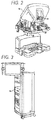
- FIG. 2 is a perspective view of the Surgeon's Console 16.
- the Surgeon's Console 16 includes a left eye display 32 and a right eye display 34 for presenting the Surgeon 18 with a coordinated stereo view of the surgical site that enables depth perception.
- the Console 16 further includes one or more input control devices 36, which in turn cause the Patient Side Cart 22 (shown in FIG. 1 ) to manipulate one or more tools.
- the input control devices 36 can provide the same degrees of freedom as their associated tools 26 (shown in FIG. 1 ) to provide the Surgeon with telepresence, or the perception that the input control devices 36 are integral with the tools 26 so that the Surgeon has a strong sense of directly controlling the tools 26.
- position, force, and tactile feedback sensors may be employed to transmit position, force, and tactile sensations from the tools 26 back to the Surgeon's hands through the input control devices 36.
- the Surgeon's Console 16 is usually located in the same room as the patient so that the Surgeon may directly monitor the procedure, be physically present if necessary, and speak to an Assistant directly rather than over the telephone or other communication medium. However, the Surgeon can be located in a different room, a completely different building, or other remote location from the Patient allowing for remote surgical procedures.
- FIG. 3 is a perspective view of the Electronics Cart 24.
- the Electronics Cart 24 can be coupled with the endoscope 28 and can include a processor to process captured images for subsequent display, such as to a Surgeon on the Surgeon's Console, or on another suitable display located locally and/or remotely.
- the Electronics Cart 24 can process the captured images to present the Surgeon with coordinated stereo images of the surgical site.
- Such coordination can include alignment between the opposing images and can include adjusting the stereo working distance of the stereoscopic endoscope.
- image processing can include the use of previously determined camera calibration parameters to compensate for imaging errors of the image capture device, such as optical aberrations.
- FIG. 4 diagrammatically illustrates a robotic surgery system 50 (such as MIRS system 10 of FIG. 1 ).
- a Surgeon's Console 52 (such as Surgeon's Console 16 in FIG. 1 ) can be used by a Surgeon to control a Patient Side Cart (Surgical Robot) 54 (such as Patent Side Cart 22 in FIG. 1 ) during a minimally invasive procedure.
- the Patient Side Cart 54 can use an imaging device, such as a stereoscopic endoscope, to capture images of the procedure site and output the captured images to an Electronics Cart 56 (such as the Electronics Cart 24 in FIG. 1 ).
- the Electronics Cart 56 can process the captured images in a variety of ways prior to any subsequent display.
- the Electronics Cart 56 can overlay the captured images with a virtual control interface prior to displaying the combined images to the Surgeon via the Surgeon's Console 52.
- the Patient Side Cart 54 can output the captured images for processing outside the Electronics Cart 56.
- the Patient Side Cart 54 can output the captured images to a processor 58, which can be used to process the captured images.
- the images can also be processed by a combination the Electronics Cart 56 and the processor 58, which can be coupled together to process the captured images jointly, sequentially, and/or combinations thereof.
- One or more separate displays 60 can also be coupled with the processor 58 and/or the Electronics Cart 56 for local and/or remote display of images, such as images of the procedure site, or other related images.
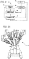
- FIGS. 5A and 5B show a Patient Side Cart 22 and a surgical tool 62, respectively.
- the surgical tool 62 is an example of the surgical tools 26.
- the Patient Side Cart 22 shown provides for the manipulation of three surgical tools 26 and an imaging device 28, such as a stereoscopic endoscope used for the capture of images of the site of the procedure. Manipulation is provided by robotic mechanisms having a number of robotic joints.
- the imaging device 28 and the surgical tools 26 can be positioned and manipulated through incisions in the patient so that a kinematic remote center is maintained at the incision to minimize the size of the incision.
- Images of the surgical site can include images of the distal ends of the surgical tools 26 when they are positioned within the field-of-view of the imaging device 28.
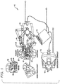
- FIG. 6 and FIG. 7 show a robotic assembly 70 that includes a carriage assembly 72 and an instrument holder assembly 74.
- the instrument holder assembly 74 includes an instrument holder base member 76 and a spar fitting 78 slideably mounted to the instrument holder base member 76.
- the carriage assembly 72 is mountable to the spar fitting 78.
- the instrument holder assembly 74 includes a carriage drive mechanism (not shown) that is operable to selectively translate the spar fitting 78 along the instrument holder base member 76, thereby translating the carriage assembly 72 along the instrument holder base member 76 along an insertion axis of a surgical instrument (not shown) mounted to the carriage assembly 72.
- the carriage assembly 72 includes five output drive couplings 80.
- Each of the output drive couplings 80 is configured to drivingly couple with a corresponding input drive coupling of a surgical instrument when the surgical instrument is mounted to the carriage assembly 72.
- Each of the five output drive couplings 80 can be independently actuated to actuate a corresponding mechanism of a mounted surgical instrument.
- one of the output drive couplings 80 can be used to rotate an elongated shaft of the surgical instrument, one can be used to articulate an end effector of the mounted surgical instrument around a first axis ( e.g ., pitch axis), one can be used to articulate the end effector around a second axis ( e .
- each of the five output drive couplings is substantially parallel to the elongate shaft of the surgical instrument. While the carriage assembly 72 includes five output drive couplings 80, a carriage assembly can be configured with any suitable number of output drive couplings.
- two of the output drive couplings can be configured to each drive a single finger of a two-finger surgical instrument.
- the relative motions of the two fingers combine to provide both grip and yaw motions of the surgical end effector.
- the two output drive couplings furthest from the surgical instrument shaft are used to drive these grip/yaw motions.
- the output drive couplings are arranged in an array so as to minimize the width of the carriage.
- a maximum of two output drive couplings can be located adjacent to one another in a width direction of the carriage (see, for example, the arrangement of the drive couplings 80 in FIG. 6 where the two drive couplings at the right side of the array of five drive couplings 80 relative to the orientation of FIG. 6 are adjacent to one another in the width direction of the carriage and likewise the two drive couplings at the left side of the array five drive couplings 80 relative to the orientation of FIG. 6 are adjacent to one another in the width direction of the carriage).
- the carriage assembly 72 also includes a radio frequency identification (RFID) antenna module 82 and a contact assembly 84.
- the RFID antenna module 82 can be used to interrogate an RFID tag on the surgical instrument or sterile adapter component, for example, to identify a mounted surgical instrument and/or to detect the presence of a mounted surgical instrument.
- the contact assembly 84 can connect to an identification chip of a mounted surgical instrument, for example, to identify a mounted surgical instrument and/or to detect the presence of a mounted surgical instrument or sterile adapter.
- the RFID antenna module 82 is designed to read the instrument RFID tag at close range, for example, between 0 mm and approximately 20 mm separation distance. The RFID tag signal can then be used as one (redundant) piece of information to help determine the approach, presence, and/or removal of the instrument from the carriage.
- FIG. 8 shows the installed arrangement of drive motors 86 used to actuate the output drive couplings 80.
- the drive motors 86 are electronically commutated motors (ECMs), which are controlled by associated electronic commutation systems.
- ECM has permanent magnets that rotate and a fixed armature thereby eliminating the need to connect current to a moving armature.
- An electronic controller replaces the brush/commutator assembly of a brushed direct current (DC) motor.
- the orientation of the rotor for each of the drive motors 86 is monitored by a sensor assembly and supplied to an electronic controller for the drive motor.
- the drive motor orientation is used by the electronic controller to control the phase of the windings of the drive motor to control rotation of the drive motor.
- the drive motors 86 are arranged in a pattern with four corner drive motors and a central drive motor disposed between the four corner drive motors.
- each of the four corner drive motors is disposed immediately adjacent to ( e.g., separated by less than five millimeters, separated by less than two millimeters) an adjacent corner drive motor and the central drive motor.
- the central drive motor is disposed immediately adjacent to each of the four corner drive motors.
- the arrangement provides open spaces on opposite sides of the central drive motor between two of the corner drive motors.
- the drive motors are a "component set" where the stator and rotor are individual components, forming a complete and functional motor only after being installed in the carriage housing.
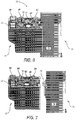
- FIG. 9 shows output assemblies 88, 90 coupled to the drive motors 86.
- Each of four of the output assemblies includes a spring-loaded output drive coupling 80 and a two-stage planetary gear box 92.
- the output assembly 90 includes a spring-loaded output drive coupling 80 and a single-stage planetary gear box 94.
- Each of the planetary gear boxes 92, 94 drivingly couple one of the spring-loaded output drive couplings 80 to a corresponding one of the drive motors 86.
- the gear ratio of the output assembly gearbox is preferably less than 40:1 in order to provide high efficiency back-drivability. High efficiency back-drivability is an important feature enabling high performance surgical motions.
- each of the two-stage planetary gear boxes 92 provides an approximately 28 to 1 gear reduction.
- the single-stage planetary gear box 94 provides an approximately 5.3 to 1 gear reduction.
- Each of the planetary gear boxes 92, 94 includes an outer housing that has a slotted aperture 96 (most of which are hidden relative to the view direction of FIG. 9 ) that is aligned with a carrier gear having external gear teeth configured to drive pinion gears that extend through the slotted aperture 96.
- Each of the externally-geared carrier gears are output links for the planetary-gear boxes 92, 94 and therefore rotate in unison with the corresponding output drive coupling 80.
- FIG. 10 shows five sensor assemblies 98 drivingly coupled to the externally-geared carrier gears of the planetary-gear boxes 92, 94.
- Each of the sensor assemblies 98 includes a pinion gear 100, a shaft assembly 102 coupled to the pinion gear 100, and a sensor target 104, the orientation of which is monitored by an absolute orientation sensor assembly (not shown).
- Each pinion gear 100 extends through one of the slotted apertures 96 to engage and be driven by the externally-geared carrier gear of the corresponding planetary gear box.
- the five drive motors 86 and associated planetary-gear boxes 92, 94 are arranged in a pattern that provides two open volumes 106, 108, which are located on opposite sides of the central drive motor.
- Each of the planetary gear boxes 92, 94 is oriented such that its slotted aperture 96 faces one of the open volumes 106, 108.
- Two of the sensor assemblies 98 are disposed in the near-side open volume 106.
- three of the sensor assemblies 98 are disposed in the far-side open volume 108.
- the pinion gears 100 for the sensor assemblies 98 that engage the corner planetary gear boxes are located in the same geometric plane as shown for the two pinion gears 100 in the near-side open volume 106.
- the pinion gear 100 for the sensor assembly 98 that engages the central planetary gear box is disposed offset from and overlaps the other two pinion gears disposed in the far-side open volume 108.
- the slotted apertures 96 have an increased width to accommodate the possible positions of the pinion gear 100 associated with the overlap between the pinion gears 100 disposed in the far-side open volume 108.
- the gear teeth of the externally-geared carrier gears have an increased width to accommodate the possible positions of the pinion gear 100 associated with the overlap between the pinion gears 100 disposed in the far-side open volume 108.
- Each shaft assembly includes a drive shaft 110, a bottom end bearing 112, a top end bearing 114, and a compression spring 116.
- the top end bearing 114 can be translated along the drive shaft 110 thereby compressing the compression spring 116 to position the top end bearing 114 for lateral installation of the sensor assembly 98 into a motor housing (shown in FIG. 11 ).
- extension of the compression spring 116 repositions the top end bearing 114 into engagement with a corresponding bearing receptacle in the motor housing.
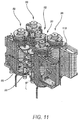
- FIG. 11 shows the motor housing 118 with the drive motors 86, planetary gear boxes 92, 94, and the sensor assemblies 98 mounted to the motor housing 118.
- the motor housing 118 is a monolithically machined component configured to accommodate and/or support the drive motors 86, the sensor assemblies 98, as well as other components of the carriage assembly 72.
- the monolithically machined motor housing 118 is made from a material having thermal conductivity greater than 70 W/m-K ( e.g ., magnesium or aluminum).
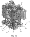
- FIG. 12 is an exploded view showing a Hall-effect sensor assembly 120 that includes a mounting frame 122 and five Hall-effect sensors 124 mounted to the mounting frame 122.
- Each of the Hall-effect sensors 124 monitors the orientation of a rotor of the corresponding drive motor 86 by providing an output signal, which changes as the alternating North and South magnetic poles of the motor rotor pass by the sensor.
- An output signal from each of the Hall-effect sensors 124 is input to an electronic controller for the corresponding drive motor.
- Each of the electronic controllers uses the orientation signal to control the phase of the windings of the corresponding drive motor to control rotation of the drive motor.
- the mounting frame 122 also includes receptacles 126 that receive and support the bottom end bearings 112 of the five sensor assemblies 98.
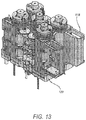
- FIG. 13 shows the Hall-effect assembly 120 mounted to the motor housing 118.
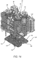
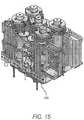
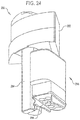
- FIG. 14 is an exploded view showing an absolute orientation sensor assembly 128 that includes a mounting frame 130 and ten orientation sensors 132 mounted to the mounting frame.
- Five of the orientation sensors 132 monitors the orientation of a corresponding one of the sensor assemblies 98, thereby monitoring the orientation of the corresponding output drive coupling 80. Additionally, five of the orientation sensors monitor the orientation of the rotor component of the drive motor. These five orientation sensors provide a second means of motor rotation sensing in addition to the Hall-effect sensor assembly.
- the orientation sensors 132 include optical sensors that sense the angular orientation of an optically readable pattern on the sensor target 104 of the corresponding sensor assembly 98, thereby sensing the orientation of the sensor target 104.
- FIG. 15 shows the orientation sensor assembly 128 mounted in its installed position.
- FIG. 16 through FIG. 18 show additional components of the carriage assembly 72.
- FIG. 16 shows the mounted positions of an electronic control assembly 134, the radio frequency identification (RFID) antenna module 82, and the contact assembly 84.
- FIG. 17 shows the mounted positions of a lower housing 136 and a side cover 138.
- FIG. 18 shows the mounted positions of an outer housing 140.
- RFID radio frequency identification
- FIG. 19 shows one of the two-stage planetary gear boxes 92 and an associated one of the output drive couplings 80.
- the output drive coupling 80 includes oppositely disposed drive receptacles 142, 144 that receive and drivingly coupled with corresponding drive extension features in a mating coupling.
- the drive receptacles 142, 144 are disposed at different radial positions, thereby ensuring only one possible angular orientation of engagement between the output drive coupling 80 and the corresponding mating coupling.
- FIG. 20 shows a cross-section of one of the two-stage planetary gear boxes 92.
- the planetary gear box 92 includes an outer housing 146, a first planetary stage 148, a second planetary stage 150, a double-row bearing 152.
- the first planetary stage 148 includes first stage planet gears 154 that interface with and are driven by a sun gear (not shown) mounted to the rotor of the corresponding drive motor 86.
- the first stage planet gears 154 are rotationally mounted to a first stage carrier 156 that is fixedly attached to a first stage output sun gear 158.
- the first stage planet gears 154 interface with an internal ring gear 160 integral to the outer housing 146.
- the second planetary stage 150 includes second stage planet gears 161 that interface with and are driven by the first stage output sun gear 158.
- the second stage planet gears 161 are rotationally mounted to a second stage carrier 162.
- the second stage planet gears 161 interface with the internal ring gear 160 integral to the outer housing 146.
- the second stage carrier 162 has external gear teeth 164 that interface with and drive the pinion gear 100 of the corresponding sensor assembly 98.
- the second stage carrier external gear teeth 164 and the aperture 96 in the outer housing 146 have a width in an axial direction of the planetary gear box 92 sized to accommodate different possible positions of the corresponding pinion gear 100 associated with the overlap of the pinion gears 100 as described herein.
- the second stage carrier 162 is fixedly coupled to an inner hollow shaft 166 that interfaces with and is supported by an inner race of the double row bearing 152.
- a retainer ring 168 interfaces with a slot in the inner hollow shaft 166 and retains the assembly of the second stage carrier 162 and the inner hollow shaft 166 relative to the inner race of the double row bearing 152.
- the double row bearing 152 includes two rows of rolling elements, which serve to constrain the second stage carrier 162 to rotate concentric to the outer housing 146.
- the double row bearing 152 is used in place of two or more separate bearings, thereby allowing the planetary gear box 92 to have a smaller length along the axial direction of the planetary gear box 92 as compared to a traditional planetary gear box having two or more separate bearings.
- the second stage carrier 162 is drivingly coupled with the output drive coupling 80 via external splines.
- a compression spring 170 biases the output drive coupling 80 into an extended position.
- the second stage carrier 162, the output drive coupling 80, and the compression spring 170 are configured so that the output drive coupling 80 can be displaced towards the planetary gear box 92 during an engagement process in which the output drive coupling 80 is rotated until oriented such that the drive receptacles 142, 144 are properly aligned with corresponding drive extension features in a mating coupling.
- the single-stage planetary gear box 94 is configured similar to the two-stage planetary gear box 92, but without the first planetary stage 148.
- FIG. 21 shows a side view of one of the drive motors 86.
- Each of the drive motors 86 includes magnetic flux shields 172 disposed at opposite ends of the drive motor.
- FIG. 22 is an exploded view showing the magnetic flux shields 172 displaced from the rest of the drive motor 86.
- each of the magnetic flux shields 172 is made from a suitable magnetically soft material (e.g., iron, cobalt, and/or nickel) having suitably high magnetic permeability.
- each magnetic flux shield 172 is configured as a thin hollow cylinder having the illustrated axial length relative to the axial length of the drive motor 86.
- the magnetic flux shields 172 are located at the ends of the drive motor 86 to entrain magnetic flux lines emanating from the magnetized motor rotor so that those magnetic flux lines do not extend adjacent to the drive motor 86 to interfere with an adjacent drive motor and/or interfere with an adjacent motor sensor.
- FIG. 23 shows a cross section of one of the drive motors 86.
- the drive motor 86 includes a rotor 174 having permanent magnets 176, a top end bearing 178, a bottom end bearing 180, an output gear 182, an orientation sensor target 184 (note that this is the target for the optical encoders shown in FIG. 14 and NOT the Hall-effect sensors shown in FIG. 12 ), an outer motor housing 186 in which motor windings 188 are disposed, the magnetic flux shields 172, and an end cap 190.
- Each of the magnetic flux shields 172 is disposed at opposing ends of the drive motor 86 so as to overlap a corresponding end of the motor windings 188.
- the location and the configuration of the magnetic flux shields 172 is selected to inhibit and/or prevent magnetic flux lines emanating from the magnetized motor rotor from interacting with an adjacent drive motor(s) and/or with one or more adjacent motor orientation sensors.
- the shields prevent the magnetic fields coming from the permanent magnets on the rotor from interacting with adjacent motors and/or sensors.
- the magnetic field coming from the stator windings is generally far weaker than the rotating permanent magnet field of the rotor and is generally not the main source of detrimental interference.
- the shields do serve to attenuate both effects.
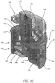
- FIG. 24 shows a robotic assembly 200, in accordance with many examples
- the robotic assembly 200 includes an insertion axis base 202, an insertion axis assembly 204, a carriage assembly 206, and a sterile adapter 208.
- the insertion axis assembly 204 is telescopic and attached to the insertion axis base 202, which can be selectively positioned and oriented via an upstream linkage (not shown).
- the carriage assembly 206 is mounted to the insertion axis assembly 204 and is selectively translatable along the insertion axis assembly 204.
- the carriage assembly 206 includes eight rotary drive assemblies configured to couple with and actuate up to a corresponding eight inputs of a surgical instrument (not shown) mounted to the carriage assembly 206.
- the sterile adapter 208 is configured to mount to the carriage assembly 206 by a snap-in interface design that provides for quick release of the sterile adapter 208.
- the sterile adapter 208 includes eight rotary couplers that drivingly couple outputs of the eight rotary drive assemblies of the carriage assembly to rotary drive inputs of a surgical instrument (not shown) mounted to the carriage assembly 206.
- the eight rotary drive assemblies include six drive assemblies used to actuate up to six rotary drive inputs of a surgical instrument and two additional rotary drive assemblies that are used to drive additional rotary drive inputs of advanced surgical instruments (e.g., stapler, vessel sealer).
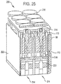
- FIG. 25 shows a drive assembly 212 of the carriage assembly 206.
- the drive assembly 212 includes eight drive assemblies 214.
- Each of the drive assemblies 214 includes a drive motor 86, a primary angular orientation sensor 216, a secondary angular orientation sensor 218, and a planetary gear box 220.
- the eight drive motors 86 of the drive assembly 212 are arranged in a two wide by four deep array.
- the drive assembly 212 includes a motor housing 222 configured to accommodate and/or support the drive motors 86, the primary angular orientation sensors 216, the secondary angular orientation sensors 218, and the planetary gear boxes 220.
- the drive motors 86 are configured similar to the drive motors 86 of the carriage assembly 72 discussed herein. As such, the description of the drive motors 86 of the carriage assembly 72 applies to the drive motors 86 of the drive assembly 212 and will therefore not be repeated here.
- each of the primary angular orientation sensors 216 is an absolute magnetic encoder that includes a magnetic sensor that tracks the absolute orientation of a magnet 224 attached to a rotor of the corresponding drive motor 86.
- the secondary angular orientation sensors 218 are compact Hall Effects sensors. The angular orientation the drive motor 86 in each of the drive assemblies 214 is redundantly tracked by the primary and secondary angular orientation sensors 216, 218, thereby providing an increased confidence level to the tracking of the angular orientation of the drive motor 86.
- the eight planetary gear boxes 220 are configured similar to the output assemblies 88, 90 of the carriage assembly 72 discussed herein. Notable differences include that the planetary gear boxes 220 include additional bearing assemblies distributed along the centerline of the gear box and are thus somewhat longer than the output assemblies 88, 90.
- the eight planetary gear boxes 220 are relatively heavy duty, highly back-drivable, efficient, have low backlash (e.g., 0.05 degree).
- Two planetary stages are used to produce a 28 to 1 gear reduction for standard low-speed drive assemblies 214 (e.g., seven of the eight drive assemblies 214).
- one planetary stage is used to produce a 5.3 to 1 gear reduction for a low-speed drive assembly 214 (e.g., one of the eight drive assemblies).
- each of the drive motors 86 includes magnetic flux shields 172 disposed at the ends of the drive motors 86.
- the flux shields 172 serve to entrain magnetic flux lines emanating from the magnetized motor rotor so that those magnetic flux lines do not extend adjacent to the drive motor 86 to interfere with an adjacent drive motor and/or interfere with an adjacent primary and/or secondary angular orientation sensor 216, 218.
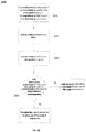
- FIG. 26 illustrates a method 2600 for a mid-procedure restart of a surgical device that is driven by a motor, for example, such as any of the motors disclosed herein, and, for example, any of the motors disclosed within the instrument manipulator disclosed US Patent Publication No. US 2013/0209208 (Attorney Docket No. ISRG03640/US), entitled "COMPACT NEEDLE MANIPULATOR FOR TARGETED INTERVENTIONS". Examples of applicable surgical devices can be found at Int'l. Pub. No. WO 2011/060318 (Attorney Docket No.: ISRG02360/PCT); U.S. Patent Publication No. US 2011/118778 (Attorney Docket No.
- a controller continually records to non-volatile memory rotational position of a drive mechanism for a telesurgical controlled surgical instrument during a procedure.
- sensors of any of the orientation sensors disclosed above, such as those of the orientation sensor assembly 128 can continually record sensor orientation to non-volatile memory. Data is stored at a rate such that when the tool is moving rapidly, there is still enough resolution to estimate where it should be upon restart.
- a mid-procedure shutdown is initiated by the controller.
- the surgical device is held in location it was in directly before the shutdown took place.
- a fault condition for a surgical device occurs during a patient procedure.
- the system will perform an automated safety shutdown such that continued use of the surgical device is halted by the controller.
- shut down of a device may optionally occur for any reason not due to a default condition. In either case, continued use of the surgical device can occur by initiating a restart procedure.
- the controller receives a request to initiate a mid-procedure restart of the surgical device.
- post-shutdown position e.g. of one or more effector mechanisms and/or rotatable shafts
- post-shutdown position e.g. of one or more effector mechanisms and/or rotatable shafts
- a surgical device with a rotational shaft may be in a clamped mode (onto tissues) when shutdown.
- force from wound springs in motor assemblies can back drive motors and/or transmissions. Movement can also occur as a result of a technician manipulating a portion of the surgical device to resolve a default condition.
- clamped and/or twisted resilient tissue can provide a counter-force to force applying mechanisms within the surgical device.
- Surgical devices for telesurgery systems are often demountable, and thus modular in nature, and include inputs driven by disc-like drivers, such as the output assemblies 88 disclosed above.
- sensors can be located within the surgical instrument as well.
- Rotational position of an aspect of a surgical instrument can be interpolated by recording rotational positions of one or more locations of driver mechanisms that interface with the surgical instrument, and applying a mathematical formula to the recorded positions based on known relationships.
- a vernier-like calibration for restoration of mid-procedure joint position can be applied to some mechanisms by comparing the primary sensor (before the gearbox) to the secondary sensor (after the gearbox).
- the controller can determine not only at what angle the disc was (between 0 and 360 degrees for example) but also which turn the mechanism was using. In some examples, the controller can distinguish difference of up to 3 turns of rotation. This is useful for surgical devices that use multi-turn inputs, for which an angular tolerance alone is not acceptable as the basis to safely initiate a start procedure.
- the controller determines whether the sensor has moved signifcantly by comparing the last known recorded position of the sensor before shutdown with the current location of the sensor, at or after the time of receiving the request to restart. If the position is the same or within an acceptable tolerance, e.g. 90 degrees, then the controller can authorize continued use of the surgical device.
- an acceptable tolerance e.g. 90 degrees
- the acceptable tolerance depends on the type of surgical device being used, since some devices may be more flexible than others with respect to restart position.
- the controller can prevent further use of the surgical device.
- a subsequent restart request can be authorized based on initiating a rehoming procedure in which the surgical device is completely removed from the telesurgical system and physically reset to a home position.
- the controller may require a completely new device to be installed in place of the old surgical device.
- the controller can incorporate a validation procedure in which the identity of the surgical device is verified before allowing the procedure to restart. This can require identifying the surgical device via an RFID tag before the shutdown, and then verifying that the RFID tag is the same before allowing the restart to commence.
Landscapes
- Health & Medical Sciences (AREA)
- Engineering & Computer Science (AREA)
- Surgery (AREA)
- Life Sciences & Earth Sciences (AREA)
- Medical Informatics (AREA)
- General Health & Medical Sciences (AREA)
- Biomedical Technology (AREA)
- Heart & Thoracic Surgery (AREA)
- Nuclear Medicine, Radiotherapy & Molecular Imaging (AREA)
- Molecular Biology (AREA)
- Animal Behavior & Ethology (AREA)
- Robotics (AREA)
- Public Health (AREA)
- Veterinary Medicine (AREA)
- Oral & Maxillofacial Surgery (AREA)
- Pathology (AREA)
- Mechanical Engineering (AREA)
- Manipulator (AREA)
Description
- This application claims the benefit of
U.S. Provisional Application No. 61/954,561, filed March 17, 2014 - Minimally invasive medical techniques are intended to reduce the amount of extraneous tissue that is damaged during diagnostic or surgical procedures, thereby reducing patient recovery time, discomfort, and deleterious side effects. One effect of minimally invasive surgery, for example, is reduced post-operative hospital recovery times. Because the average hospital stay for a standard surgery is typically significantly longer than the average stay for an analogous minimally invasive surgery, increased use of minimally invasive techniques could save millions of dollars in hospital costs each year. While many of the surgeries performed each year in the United States could potentially be performed in a minimally invasive manner, only a portion of the current surgeries use these advantageous techniques due to limitations in minimally invasive surgical instruments and the additional surgical training involved in mastering them.
- Minimally invasive robotic surgical or telesurgical systems have been developed to increase a surgeon's dexterity and avoid some of the limitations on traditional minimally invasive techniques. In telesurgery, the surgeon uses some form of remote control (e.g., a servomechanism or the like) to manipulate surgical instrument movements, rather than directly holding and moving the instruments by hand. In telesurgery systems, the surgeon can be provided with an image of the surgical site at a surgical workstation. While viewing a two or three dimensional image of the surgical site on a display, the surgeon performs the surgical procedures on the patient by manipulating master control devices, which in turn control motion of the servo-mechanically operated instruments.
- The servomechanism used for telesurgery will often accept input from two master controllers (one for each of the surgeon's hands) and may include two or more robotic arms on each of which a surgical instrument is mounted. Operative communication between master controllers and associated robotic arm and instrument assemblies is typically achieved through a control system. The control system typically includes at least one processor that relays input commands from the master controllers to the associated robotic arm and instrument assemblies and back from the instrument and arm assemblies to the associated master controllers in the case of, for example, force feedback or the like. One example of a robotic surgical system is the DA VINCI® system available from Intuitive Surgical, Inc. of Sunnyvale, Calif.
- A variety of structural arrangements can be used to support the surgical instrument at the surgical site during robotic surgery. The driven linkage or "slave" is often called a robotic surgical manipulator, and exemplary linkage arrangements for use as a robotic surgical manipulator during minimally invasive robotic surgery are described in
U.S. Pat. Nos. 7,594,912 ;6,758,843 ;6,246,200 ; and5,800,423 . These linkages often make use of a parallelogram arrangement to hold an instrument having a shaft. Such a manipulator structure can constrain movement of the instrument so that the instrument pivots about a remote center of manipulation positioned in space along the length of the rigid shaft. By aligning the remote center of manipulation with the incision point to the internal surgical site (for example, with a trocar or cannula at an abdominal wall during laparoscopic surgery), an end effector of the surgical instrument can be positioned safely by moving the proximal end of the shaft using the manipulator linkage without imposing potentially dangerous forces against the abdominal wall. Alternative manipulator structures are described, for example, inU.S. Pat. Nos. 6,702,805 ;6,676,669 ;5,855,583 ;5,808,665 ;5,445,166 ; and5,184,601 . - A variety of structural arrangements can also be used to support and position the robotic surgical manipulator and the surgical instrument at the surgical site during robotic surgery. Supporting linkage mechanisms, sometimes referred to as set-up joints, or set-up joint arms, are often used to position and align each manipulator with the respective incision point in a patient's body. The supporting linkage mechanism facilitates the alignment of a surgical manipulator with a desired surgical incision point and targeted anatomy. Exemplary supporting linkage mechanisms are described in
U.S. Pat. Nos. 6,246,200 and6,788,018 . -
EP 2 601 905 A1 discloses a manipulator system control device, manipulator system, and manipulator system control method. The manipulator system comprises a slave control circuit such as the following: When the manipulator system shuts down, the slave control circuit generates shutdown identifier information that denotes the shutdown state of the manipulator system, stores the shutdown identifier information, and loads the shutdown identifier information when the manipulator system is activated. - While the new telesurgical systems and devices have proven highly effective and advantageous, still further improvements are desirable. In general, improved minimally invasive robotic surgery systems are desirable. On some occasions, use of a telesurgical device is halted mid-procedure, requiring rehoming of the device upon restart. It would be particularly beneficial if such systems were configured to safely execute a mid-procedure restart in an efficient manner.
- The present invention, as defined by the appended claims, provides a telesurgery system comprising: a surgical assembly comprising a motor and a tool, the surgical assembly having at least one rotatable drive mechanism driven by the motor; a sensor assembly coupled to non-volatile memory, the sensor assembly for recording position of the at least one rotatable drive mechanism to the non-volatile memory; and a controller communicatively coupled to the sensor assembly, the controller having at least one processor configured to execute a method comprising: recording a rotational position of the at least one rotatable drive mechanism to the non-volatile memory during use of the surgical assembly; initiating a mid-procedure shut-down of the surgical assembly; receiving a request to initiate a mid-procedure restart of the surgical assembly; determining whether a post-shutdown position of the at least one rotatable drive mechanism is within an accepted tolerance with respect to a pre-shutdown position of the at least one rotatable drive mechanism to allow the mid-procedure restart to complete; and preventing or allowing further use of the surgical assembly based on determining whether the post-shutdown position of the at least one rotatable drive mechanism is within the accepted tolerance with respect to the pre-shutdown position of the at least one rotatable drive mechanism. Also herein described is an examplary method that is executable by the at least one processor. In the method, rotational position of the at least one drive mechanism is recorded to the non-volatile memory during use of the surgical assembly. A mid-procedure shut-down of the surgical assembly is then initiated, such that use of the surgical assembly is prevented. A request is then received to initiate a mid-procedure restart of the surgical assembly. It is then determined whether a post-shutdown position of the at least one drive mechanism is within an accepted tolerance with respect to a pre-shutdown position of the at least one drive mechanism to allow the mid-procedure restart to complete. Use of the surgical assembly is allowed or prevented based on determining whether the post-shutdown position of the at least one drive mechanism is within an accepted tolerance with respect to the pre-shutdown position of the at least one drive mechanism.
- In many embodiments, determining whether the post-shutdown rotational position of the at least one rotatable drive mechanism is within the accepted tolerance includes validating authenticity of the post-shutdown rotational position.
- In many embodiments, validating the pre-shutdown rotational position comprises checking identity of the surgical instrument.
- In many embodiments, the accepted tolerance is +/- 90 degrees.
- In many embodiments, the motor drives a gearbox, and the sensory assembly includes a first sensor configured to record a first rotational position of the motor assembly at a location before the gearbox and a second sensor configured to record a second rotational position of the motor assembly at a location after the gearbox. Determining whether the post-shutdown rotational position of the at least one rotatable drive mechanism is within the accepted tolerance includes comparing the ratio of turns from the first rotational position to the second rotational position.
- In many embodiments, the at least one rotatable drive mechanism is coupled to a rotatable instrument shaft.
- In many embodiments, it is determined that the post-shutdown rotational position of the at least one rotatable drive mechanism is not within the accepted tolerance and as a result the controller prevents further use of the surgical assembly.
- In many embodiments, the controller prevents further use of the surgical assembly until the surgical instrument is demounted and remounted to the surgical assembly or until the surgical instrument is demounted and a replacement surgical instrument is mounted to the surgical assembly.
- For a fuller understanding of the nature and advantages of the present invention, reference should be made to the ensuing detailed description and accompanying drawing. Other aspects, objects and advantages of the invention will be apparent from the drawings and detailed description that follows.
-
-
FIG. 1 is a plan view of a minimally invasive robotic surgery system being used to perform a surgery, in accordance with many embodiments. -
FIG. 2 is a perspective view of a surgeon's control console for a robotic surgery system, in accordance with many embodiments. -
FIG. 3 is a perspective view of a robotic surgery system electronics cart, in accordance with many embodiments. -
FIG. 4 diagrammatically illustrates a robotic surgery system, in accordance with many embodiments. -
FIG. 5A is a partial view of a patient side cart (surgical robot) of a robotic surgery system, in accordance with many embodiments. -
FIG. 5B is a front view of a robotic surgery tool, in accordance with many embodiments. -
FIG. 6 shows a robotic assembly that includes a carriage assembly slideably mounted to an instrument holder base member for selective translation along an insertion axis of a surgical instrument mounted to the carriage assembly. -
FIG. 7 shows the robotic assembly ofFIG. 6 with the carriage assembly shown decoupled from the instrument holder base member. -
FIG. 8 through FIG. 18 is a sequence of figures that illustrate components of the carriage assembly ofFIG. 6 . -
FIG. 8 shows the as installed arrangement of drive motors of the carriage assembly ofFIG. 6 . -
FIG. 9 shows planetary gear boxes attached to the drive motors ofFIG. 8 . -
FIG. 10 shows sensor shafts coupled to output gears of the planetary gear boxes ofFIG. 9 . -
FIG. 11 shows a motor housing supporting the components ofFIG. 10 . -
FIG. 12 is an exploded view illustrating a resolver assembly that monitors the rotational orientation of the drive motors of the carriage assembly ofFIG. 6 . -
FIG. 13 shows the installed resolver assembly ofFIG. 12 . -
FIG. 14 is an exploded view illustrating an orientation sensor assembly that monitors the rotational orientation of the sensor shafts ofFIG. 10 . -
FIG. 15 shows the installed orientation sensor assembly ofFIG. 14 . -
FIG. 16 shows an electronic control assembly, a radio frequency identification (RFID) antenna, and a contact assembly for the carriage assembly ofFIG. 6 . -
FIG. 17 andFIG. 18 show outer housing components of the carriage assembly ofFIG. 6 . -
FIG. 19 shows one of the planetary gear boxes ofFIG. 9 . -
FIG. 20 shows a cross-section of the planetary gear box ofFIG. 19 . -
FIG. 21 shows one of the drive motors ofFIG. 8 . -
FIG. 22 is an exploded view of the drive motor ofFIG. 21 and illustrates ferrous end rings that serve as magnetic flux shields. -
FIG. 23 shows a cross-section of the drive motor ofFIG. 21 . -
FIG. 24 shows a robotic assembly that includes a carriage assembly slideably mounted to an instrument holder base member for selective translation along an insertion axis of a surgical instrument mounted to the carriage assembly. -
FIG. 25 shows a drive assembly of the carriage assembly ofFIG. 24 . -
FIG. 26 shows a flow chart of method for a midprocedure restart, in accordance with many embodiments. - In the following description, various embodiments of the present invention will be described. For purposes of explanation, specific configurations and details are set forth in order to provide a thorough understanding of the embodiments. However, it will also be apparent to one skilled in the art that the present invention may be practiced without the specific details. Furthermore, well-known features may be omitted or simplified in order not to obscure the embodiment being described. In the following description, various optional examples and aspects are disclosed that do not form part of the invention but are described merely to aid in understanding the invention.
- Referring now to the drawings, in which like reference numerals represent like parts throughout the several views,
FIG. 1 is a plan view illustration of a Minimally Invasive Robotic Surgical (MIRS) system 10, typically used for performing a minimally invasive diagnostic or surgical procedure on a Patient 12 who is lying down on an Operating table 14. The system can include a Surgeon's Console 16 for use by aSurgeon 18 during the procedure. One or more Assistants 20 may also participate in the procedure. The MIRS system 10 can further include a Patient Side Cart 22 (surgical robot) and an Electronics Cart 24. ThePatient Side Cart 22 can manipulate at least one removably coupled tool assembly 26 (hereinafter simply referred to as a "tool") through a minimally invasive incision in the body of the Patient 12 while theSurgeon 18 views the surgical site through the Console 16. An image of the surgical site can be obtained by an endoscope 28, such as a stereoscopic endoscope, which can be manipulated by thePatient Side Cart 22 to orient the endoscope 28. The Electronics Cart 24 can be used to process the images of the surgical site for subsequent display to theSurgeon 18 through the Surgeon's Console 16. The number of surgical tools 26 used at one time will generally depend on the diagnostic or surgical procedure and the space constraints within the operating room among other factors. If it is necessary to change one or more of the tools 26 being used during a procedure, an Assistant 20 may remove the tool 26 from thePatient Side Cart 22, and replace it with another tool 26 from a tray 30 in the operating room. -
FIG. 2 is a perspective view of the Surgeon's Console 16. The Surgeon's Console 16 includes a left eye display 32 and a right eye display 34 for presenting theSurgeon 18 with a coordinated stereo view of the surgical site that enables depth perception. The Console 16 further includes one or more input control devices 36, which in turn cause the Patient Side Cart 22 (shown inFIG. 1 ) to manipulate one or more tools. The input control devices 36 can provide the same degrees of freedom as their associated tools 26 (shown inFIG. 1 ) to provide the Surgeon with telepresence, or the perception that the input control devices 36 are integral with the tools 26 so that the Surgeon has a strong sense of directly controlling the tools 26. To this end, position, force, and tactile feedback sensors (not shown) may be employed to transmit position, force, and tactile sensations from the tools 26 back to the Surgeon's hands through the input control devices 36. - The Surgeon's Console 16 is usually located in the same room as the patient so that the Surgeon may directly monitor the procedure, be physically present if necessary, and speak to an Assistant directly rather than over the telephone or other communication medium. However, the Surgeon can be located in a different room, a completely different building, or other remote location from the Patient allowing for remote surgical procedures.
-
FIG. 3 is a perspective view of the Electronics Cart 24. The Electronics Cart 24 can be coupled with the endoscope 28 and can include a processor to process captured images for subsequent display, such as to a Surgeon on the Surgeon's Console, or on another suitable display located locally and/or remotely. For example, where a stereoscopic endoscope is used, the Electronics Cart 24 can process the captured images to present the Surgeon with coordinated stereo images of the surgical site. Such coordination can include alignment between the opposing images and can include adjusting the stereo working distance of the stereoscopic endoscope. As another example, image processing can include the use of previously determined camera calibration parameters to compensate for imaging errors of the image capture device, such as optical aberrations. -
FIG. 4 diagrammatically illustrates a robotic surgery system 50 (such as MIRS system 10 ofFIG. 1 ). As discussed above, a Surgeon's Console 52 (such as Surgeon's Console 16 inFIG. 1 ) can be used by a Surgeon to control a Patient Side Cart (Surgical Robot) 54 (such asPatent Side Cart 22 inFIG. 1 ) during a minimally invasive procedure. The Patient Side Cart 54 can use an imaging device, such as a stereoscopic endoscope, to capture images of the procedure site and output the captured images to an Electronics Cart 56 (such as the Electronics Cart 24 inFIG. 1 ). As discussed above, the Electronics Cart 56 can process the captured images in a variety of ways prior to any subsequent display. For example, the Electronics Cart 56 can overlay the captured images with a virtual control interface prior to displaying the combined images to the Surgeon via the Surgeon's Console 52. The Patient Side Cart 54 can output the captured images for processing outside the Electronics Cart 56. For example, the Patient Side Cart 54 can output the captured images to a processor 58, which can be used to process the captured images. The images can also be processed by a combination the Electronics Cart 56 and the processor 58, which can be coupled together to process the captured images jointly, sequentially, and/or combinations thereof. One or more separate displays 60 can also be coupled with the processor 58 and/or the Electronics Cart 56 for local and/or remote display of images, such as images of the procedure site, or other related images. -
FIGS. 5A and5B show aPatient Side Cart 22 and a surgical tool 62, respectively. The surgical tool 62 is an example of the surgical tools 26. ThePatient Side Cart 22 shown provides for the manipulation of three surgical tools 26 and an imaging device 28, such as a stereoscopic endoscope used for the capture of images of the site of the procedure. Manipulation is provided by robotic mechanisms having a number of robotic joints. The imaging device 28 and the surgical tools 26 can be positioned and manipulated through incisions in the patient so that a kinematic remote center is maintained at the incision to minimize the size of the incision. Images of the surgical site can include images of the distal ends of the surgical tools 26 when they are positioned within the field-of-view of the imaging device 28. -
FIG. 6 and FIG. 7 show arobotic assembly 70 that includes acarriage assembly 72 and aninstrument holder assembly 74. Theinstrument holder assembly 74 includes an instrumentholder base member 76 and a spar fitting 78 slideably mounted to the instrumentholder base member 76. Thecarriage assembly 72 is mountable to thespar fitting 78. Theinstrument holder assembly 74 includes a carriage drive mechanism (not shown) that is operable to selectively translate the spar fitting 78 along the instrumentholder base member 76, thereby translating thecarriage assembly 72 along the instrumentholder base member 76 along an insertion axis of a surgical instrument (not shown) mounted to thecarriage assembly 72. - The
carriage assembly 72 includes fiveoutput drive couplings 80. Each of theoutput drive couplings 80 is configured to drivingly couple with a corresponding input drive coupling of a surgical instrument when the surgical instrument is mounted to thecarriage assembly 72. Each of the fiveoutput drive couplings 80 can be independently actuated to actuate a corresponding mechanism of a mounted surgical instrument. For example, one of theoutput drive couplings 80 can be used to rotate an elongated shaft of the surgical instrument, one can be used to articulate an end effector of the mounted surgical instrument around a first axis (e.g., pitch axis), one can be used to articulate the end effector around a second axis (e.g., yaw axis) that is perpendicular to the first axis, one can be used to articulate a clamping jaw of the end effector, and one can be used to articulate a stapling and cutting cartridge of the end effector. In a preferred example, the rotation axis of each of the five output drive couplings is substantially parallel to the elongate shaft of the surgical instrument. While thecarriage assembly 72 includes fiveoutput drive couplings 80, a carriage assembly can be configured with any suitable number of output drive couplings. - In many examples, two of the output drive couplings can be configured to each drive a single finger of a two-finger surgical instrument. The relative motions of the two fingers combine to provide both grip and yaw motions of the surgical end effector. In many examples, the two output drive couplings furthest from the surgical instrument shaft are used to drive these grip/yaw motions.
- Also in a preferred example, the output drive couplings are arranged in an array so as to minimize the width of the carriage. For example, a maximum of two output drive couplings can be located adjacent to one another in a width direction of the carriage (see, for example, the arrangement of the
drive couplings 80 inFIG. 6 where the two drive couplings at the right side of the array of fivedrive couplings 80 relative to the orientation ofFIG. 6 are adjacent to one another in the width direction of the carriage and likewise the two drive couplings at the left side of the array fivedrive couplings 80 relative to the orientation ofFIG. 6 are adjacent to one another in the width direction of the carriage). - The
carriage assembly 72 also includes a radio frequency identification (RFID)antenna module 82 and acontact assembly 84. TheRFID antenna module 82 can be used to interrogate an RFID tag on the surgical instrument or sterile adapter component, for example, to identify a mounted surgical instrument and/or to detect the presence of a mounted surgical instrument. Thecontact assembly 84 can connect to an identification chip of a mounted surgical instrument, for example, to identify a mounted surgical instrument and/or to detect the presence of a mounted surgical instrument or sterile adapter. In a preferred example, theRFID antenna module 82 is designed to read the instrument RFID tag at close range, for example, between 0 mm and approximately 20 mm separation distance. The RFID tag signal can then be used as one (redundant) piece of information to help determine the approach, presence, and/or removal of the instrument from the carriage. -
FIG. 8 shows the installed arrangement ofdrive motors 86 used to actuate theoutput drive couplings 80. In many examples, thedrive motors 86 are electronically commutated motors (ECMs), which are controlled by associated electronic commutation systems. An ECM has permanent magnets that rotate and a fixed armature thereby eliminating the need to connect current to a moving armature. An electronic controller replaces the brush/commutator assembly of a brushed direct current (DC) motor. The orientation of the rotor for each of thedrive motors 86 is monitored by a sensor assembly and supplied to an electronic controller for the drive motor. The drive motor orientation is used by the electronic controller to control the phase of the windings of the drive motor to control rotation of the drive motor. Thedrive motors 86 are arranged in a pattern with four corner drive motors and a central drive motor disposed between the four corner drive motors. In the illustrated arrangement, each of the four corner drive motors is disposed immediately adjacent to (e.g., separated by less than five millimeters, separated by less than two millimeters) an adjacent corner drive motor and the central drive motor. And the central drive motor is disposed immediately adjacent to each of the four corner drive motors. The arrangement provides open spaces on opposite sides of the central drive motor between two of the corner drive motors. In a preferred example, the drive motors are a "component set" where the stator and rotor are individual components, forming a complete and functional motor only after being installed in the carriage housing. -
FIG. 9 showsoutput assemblies 88, 90 coupled to thedrive motors 86. Each of four of the output assemblies (output assemblies 88) includes a spring-loadedoutput drive coupling 80 and a two-stageplanetary gear box 92. Theoutput assembly 90 includes a spring-loadedoutput drive coupling 80 and a single-stage planetary gear box 94. Each of theplanetary gear boxes 92, 94 drivingly couple one of the spring-loadedoutput drive couplings 80 to a corresponding one of thedrive motors 86. In many examples, the gear ratio of the output assembly gearbox is preferably less than 40:1 in order to provide high efficiency back-drivability. High efficiency back-drivability is an important feature enabling high performance surgical motions. In a preferred example, each of the two-stageplanetary gear boxes 92 provides an approximately 28 to 1 gear reduction. The single-stage planetary gear box 94 provides an approximately 5.3 to 1 gear reduction. Each of theplanetary gear boxes 92, 94 includes an outer housing that has a slotted aperture 96 (most of which are hidden relative to the view direction ofFIG. 9 ) that is aligned with a carrier gear having external gear teeth configured to drive pinion gears that extend through the slottedaperture 96. Each of the externally-geared carrier gears are output links for the planetary-gear boxes 92, 94 and therefore rotate in unison with the correspondingoutput drive coupling 80. -
FIG. 10 shows fivesensor assemblies 98 drivingly coupled to the externally-geared carrier gears of the planetary-gear boxes 92, 94. Each of thesensor assemblies 98 includes apinion gear 100, a shaft assembly 102 coupled to thepinion gear 100, and asensor target 104, the orientation of which is monitored by an absolute orientation sensor assembly (not shown). Eachpinion gear 100 extends through one of the slottedapertures 96 to engage and be driven by the externally-geared carrier gear of the corresponding planetary gear box. The fivedrive motors 86 and associated planetary-gear boxes 92, 94 are arranged in a pattern that provides twoopen volumes planetary gear boxes 92, 94 is oriented such that its slottedaperture 96 faces one of theopen volumes sensor assemblies 98 are disposed in the near-sideopen volume 106. And three of thesensor assemblies 98 are disposed in the far-sideopen volume 108. The pinion gears 100 for thesensor assemblies 98 that engage the corner planetary gear boxes are located in the same geometric plane as shown for the two pinion gears 100 in the near-sideopen volume 106. Thepinion gear 100 for thesensor assembly 98 that engages the central planetary gear box is disposed offset from and overlaps the other two pinion gears disposed in the far-sideopen volume 108. In many examples, the slottedapertures 96 have an increased width to accommodate the possible positions of thepinion gear 100 associated with the overlap between the pinion gears 100 disposed in the far-sideopen volume 108. Likewise, in many examples, the gear teeth of the externally-geared carrier gears have an increased width to accommodate the possible positions of thepinion gear 100 associated with the overlap between the pinion gears 100 disposed in the far-sideopen volume 108. - Each shaft assembly includes a drive shaft 110, a bottom end bearing 112, a top end bearing 114, and a compression spring 116. The top end bearing 114 can be translated along the drive shaft 110 thereby compressing the compression spring 116 to position the top end bearing 114 for lateral installation of the
sensor assembly 98 into a motor housing (shown inFIG. 11 ). Once installed into the motor housing, extension of the compression spring 116 repositions the top end bearing 114 into engagement with a corresponding bearing receptacle in the motor housing. -
FIG. 11 shows themotor housing 118 with thedrive motors 86,planetary gear boxes 92, 94, and thesensor assemblies 98 mounted to themotor housing 118. In many examples, themotor housing 118 is a monolithically machined component configured to accommodate and/or support thedrive motors 86, thesensor assemblies 98, as well as other components of thecarriage assembly 72. In a preferred example, the monolithically machinedmotor housing 118 is made from a material having thermal conductivity greater than 70 W/m-K (e.g., magnesium or aluminum). -
FIG. 12 is an exploded view showing a Hall-effect sensor assembly 120 that includes a mounting frame 122 and five Hall-effect sensors 124 mounted to the mounting frame 122. Each of the Hall-effect sensors 124 monitors the orientation of a rotor of thecorresponding drive motor 86 by providing an output signal, which changes as the alternating North and South magnetic poles of the motor rotor pass by the sensor. An output signal from each of the Hall-effect sensors 124 is input to an electronic controller for the corresponding drive motor. Each of the electronic controllers uses the orientation signal to control the phase of the windings of the corresponding drive motor to control rotation of the drive motor. The mounting frame 122 also includesreceptacles 126 that receive and support thebottom end bearings 112 of the fivesensor assemblies 98.FIG. 13 shows the Hall-effect assembly 120 mounted to themotor housing 118. -
FIG. 14 is an exploded view showing an absoluteorientation sensor assembly 128 that includes a mounting frame 130 and tenorientation sensors 132 mounted to the mounting frame. Five of theorientation sensors 132 monitors the orientation of a corresponding one of thesensor assemblies 98, thereby monitoring the orientation of the correspondingoutput drive coupling 80. Additionally, five of the orientation sensors monitor the orientation of the rotor component of the drive motor. These five orientation sensors provide a second means of motor rotation sensing in addition to the Hall-effect sensor assembly. In many examples, theorientation sensors 132 include optical sensors that sense the angular orientation of an optically readable pattern on thesensor target 104 of the correspondingsensor assembly 98, thereby sensing the orientation of thesensor target 104.FIG. 15 shows theorientation sensor assembly 128 mounted in its installed position. -
FIG. 16 through FIG. 18 show additional components of thecarriage assembly 72.FIG. 16 shows the mounted positions of anelectronic control assembly 134, the radio frequency identification (RFID)antenna module 82, and thecontact assembly 84.FIG. 17 shows the mounted positions of a lower housing 136 and a side cover 138. AndFIG. 18 shows the mounted positions of an outer housing 140. -
FIG. 19 shows one of the two-stageplanetary gear boxes 92 and an associated one of theoutput drive couplings 80. Theoutput drive coupling 80 includes oppositely disposed drive receptacles 142, 144 that receive and drivingly coupled with corresponding drive extension features in a mating coupling. The drive receptacles 142, 144 are disposed at different radial positions, thereby ensuring only one possible angular orientation of engagement between theoutput drive coupling 80 and the corresponding mating coupling. -
FIG. 20 shows a cross-section of one of the two-stageplanetary gear boxes 92. Theplanetary gear box 92 includes an outer housing 146, a firstplanetary stage 148, a second planetary stage 150, a double-row bearing 152. The firstplanetary stage 148 includes first stage planet gears 154 that interface with and are driven by a sun gear (not shown) mounted to the rotor of thecorresponding drive motor 86. The first stage planet gears 154 are rotationally mounted to a first stage carrier 156 that is fixedly attached to a first stage output sun gear 158. The first stage planet gears 154 interface with an internal ring gear 160 integral to the outer housing 146. The second planetary stage 150 includes second stage planet gears 161 that interface with and are driven by the first stage output sun gear 158. The second stage planet gears 161 are rotationally mounted to a second stage carrier 162. The second stage planet gears 161 interface with the internal ring gear 160 integral to the outer housing 146. The second stage carrier 162 has external gear teeth 164 that interface with and drive thepinion gear 100 of the correspondingsensor assembly 98. The second stage carrier external gear teeth 164 and theaperture 96 in the outer housing 146 have a width in an axial direction of theplanetary gear box 92 sized to accommodate different possible positions of thecorresponding pinion gear 100 associated with the overlap of the pinion gears 100 as described herein. - The second stage carrier 162 is fixedly coupled to an inner hollow shaft 166 that interfaces with and is supported by an inner race of the double row bearing 152. A retainer ring 168 interfaces with a slot in the inner hollow shaft 166 and retains the assembly of the second stage carrier 162 and the inner hollow shaft 166 relative to the inner race of the double row bearing 152. The double row bearing 152 includes two rows of rolling elements, which serve to constrain the second stage carrier 162 to rotate concentric to the outer housing 146. With the additional rotational constraint provided by the double row bearing 152, the double row bearing 152 is used in place of two or more separate bearings, thereby allowing the
planetary gear box 92 to have a smaller length along the axial direction of theplanetary gear box 92 as compared to a traditional planetary gear box having two or more separate bearings. - The second stage carrier 162 is drivingly coupled with the
output drive coupling 80 via external splines. Acompression spring 170 biases theoutput drive coupling 80 into an extended position. The second stage carrier 162, theoutput drive coupling 80, and thecompression spring 170 are configured so that theoutput drive coupling 80 can be displaced towards theplanetary gear box 92 during an engagement process in which theoutput drive coupling 80 is rotated until oriented such that the drive receptacles 142, 144 are properly aligned with corresponding drive extension features in a mating coupling. The single-stage planetary gear box 94 is configured similar to the two-stageplanetary gear box 92, but without the firstplanetary stage 148. -
FIG. 21 shows a side view of one of thedrive motors 86. Each of thedrive motors 86 includes magnetic flux shields 172 disposed at opposite ends of the drive motor.FIG. 22 is an exploded view showing the magnetic flux shields 172 displaced from the rest of thedrive motor 86. In many examples, each of the magnetic flux shields 172 is made from a suitable magnetically soft material (e.g., iron, cobalt, and/or nickel) having suitably high magnetic permeability. In the illustrated example, eachmagnetic flux shield 172 is configured as a thin hollow cylinder having the illustrated axial length relative to the axial length of thedrive motor 86. The magnetic flux shields 172 are located at the ends of thedrive motor 86 to entrain magnetic flux lines emanating from the magnetized motor rotor so that those magnetic flux lines do not extend adjacent to thedrive motor 86 to interfere with an adjacent drive motor and/or interfere with an adjacent motor sensor. -
FIG. 23 shows a cross section of one of thedrive motors 86. Thedrive motor 86 includes a rotor 174 having permanent magnets 176, a top end bearing 178, a bottom end bearing 180, anoutput gear 182, an orientation sensor target 184 (note that this is the target for the optical encoders shown inFIG. 14 and NOT the Hall-effect sensors shown inFIG. 12 ), anouter motor housing 186 in whichmotor windings 188 are disposed, the magnetic flux shields 172, and an end cap 190. Each of the magnetic flux shields 172 is disposed at opposing ends of thedrive motor 86 so as to overlap a corresponding end of themotor windings 188. The location and the configuration of the magnetic flux shields 172 is selected to inhibit and/or prevent magnetic flux lines emanating from the magnetized motor rotor from interacting with an adjacent drive motor(s) and/or with one or more adjacent motor orientation sensors. The shields prevent the magnetic fields coming from the permanent magnets on the rotor from interacting with adjacent motors and/or sensors. The magnetic field coming from the stator windings is generally far weaker than the rotating permanent magnet field of the rotor and is generally not the main source of detrimental interference. The shields, however, do serve to attenuate both effects. -
FIG. 24 shows arobotic assembly 200, in accordance with many examples Therobotic assembly 200 includes aninsertion axis base 202, aninsertion axis assembly 204, acarriage assembly 206, and a sterile adapter 208. Theinsertion axis assembly 204 is telescopic and attached to theinsertion axis base 202, which can be selectively positioned and oriented via an upstream linkage (not shown). Thecarriage assembly 206 is mounted to theinsertion axis assembly 204 and is selectively translatable along theinsertion axis assembly 204. Thecarriage assembly 206 includes eight rotary drive assemblies configured to couple with and actuate up to a corresponding eight inputs of a surgical instrument (not shown) mounted to thecarriage assembly 206. The sterile adapter 208 is configured to mount to thecarriage assembly 206 by a snap-in interface design that provides for quick release of the sterile adapter 208. The sterile adapter 208 includes eight rotary couplers that drivingly couple outputs of the eight rotary drive assemblies of the carriage assembly to rotary drive inputs of a surgical instrument (not shown) mounted to thecarriage assembly 206. In many examples, the eight rotary drive assemblies include six drive assemblies used to actuate up to six rotary drive inputs of a surgical instrument and two additional rotary drive assemblies that are used to drive additional rotary drive inputs of advanced surgical instruments (e.g., stapler, vessel sealer). -
FIG. 25 shows a drive assembly 212 of thecarriage assembly 206. The drive assembly 212 includes eightdrive assemblies 214. Each of thedrive assemblies 214 includes adrive motor 86, a primaryangular orientation sensor 216, a secondaryangular orientation sensor 218, and aplanetary gear box 220. The eightdrive motors 86 of the drive assembly 212 are arranged in a two wide by four deep array. The drive assembly 212 includes amotor housing 222 configured to accommodate and/or support thedrive motors 86, the primaryangular orientation sensors 216, the secondaryangular orientation sensors 218, and theplanetary gear boxes 220. - The
drive motors 86 are configured similar to thedrive motors 86 of thecarriage assembly 72 discussed herein. As such, the description of thedrive motors 86 of thecarriage assembly 72 applies to thedrive motors 86 of the drive assembly 212 and will therefore not be repeated here. - Any suitable angular orientation sensors can be used for the primary and secondary
angular orientation sensors angular orientation sensors 216 is an absolute magnetic encoder that includes a magnetic sensor that tracks the absolute orientation of amagnet 224 attached to a rotor of thecorresponding drive motor 86. And in many examples, the secondaryangular orientation sensors 218 are compact Hall Effects sensors. The angular orientation thedrive motor 86 in each of thedrive assemblies 214 is redundantly tracked by the primary and secondaryangular orientation sensors drive motor 86. - The eight
planetary gear boxes 220 are configured similar to theoutput assemblies 88, 90 of thecarriage assembly 72 discussed herein. Notable differences include that theplanetary gear boxes 220 include additional bearing assemblies distributed along the centerline of the gear box and are thus somewhat longer than theoutput assemblies 88, 90. The eightplanetary gear boxes 220 are relatively heavy duty, highly back-drivable, efficient, have low backlash (e.g., 0.05 degree). Two planetary stages are used to produce a 28 to 1 gear reduction for standard low-speed drive assemblies 214 (e.g., seven of the eight drive assemblies 214). And one planetary stage is used to produce a 5.3 to 1 gear reduction for a low-speed drive assembly 214 (e.g., one of the eight drive assemblies). - As discussed herein, each of the
drive motors 86 includes magnetic flux shields 172 disposed at the ends of thedrive motors 86. The flux shields 172 serve to entrain magnetic flux lines emanating from the magnetized motor rotor so that those magnetic flux lines do not extend adjacent to thedrive motor 86 to interfere with an adjacent drive motor and/or interfere with an adjacent primary and/or secondaryangular orientation sensor -
FIG. 26 illustrates amethod 2600 for a mid-procedure restart of a surgical device that is driven by a motor, for example, such as any of the motors disclosed herein, and, for example, any of the motors disclosed within the instrument manipulator disclosed US Patent Publication No.US 2013/0209208 (Attorney Docket No. ISRG03640/US), entitled "COMPACT NEEDLE MANIPULATOR FOR TARGETED INTERVENTIONS". Examples of applicable surgical devices can be found at Int'l. Pub. No.WO 2011/060318 (Attorney Docket No.: ISRG02360/PCT);U.S. Patent Publication No. US 2011/118778 (Attorney Docket No. ISRG02330/US); Patent Publication No.US 2013/0211401 (Attorney Docket No. ISRG03630/US), entitled "MINIMALLY INVASIVE SURGICAL INSTRUMENT TO PROVIDE NEEDLE-BASED THERAPY"; and Patent Publication No.US 2011/0313449 (Attorney Docket No. ISRG02760), entitled "SCISSOR BIAS FOR DIRECT PULL SURGICAL INSTRUMENT". - At
operation 2602 of themethod 2600, a controller continually records to non-volatile memory rotational position of a drive mechanism for a telesurgical controlled surgical instrument during a procedure. For example, sensors of any of the orientation sensors disclosed above, such as those of theorientation sensor assembly 128 can continually record sensor orientation to non-volatile memory. Data is stored at a rate such that when the tool is moving rapidly, there is still enough resolution to estimate where it should be upon restart. - At
operation 2604 of themethod 2600, a mid-procedure shutdown is initiated by the controller. Hence, the surgical device is held in location it was in directly before the shutdown took place. Rarely, a fault condition for a surgical device occurs during a patient procedure. When this occurs, the system will perform an automated safety shutdown such that continued use of the surgical device is halted by the controller. In addition, shut down of a device may optionally occur for any reason not due to a default condition. In either case, continued use of the surgical device can occur by initiating a restart procedure. - At
operation 2606 of themethod 2600, the controller receives a request to initiate a mid-procedure restart of the surgical device. In order to safety restart use of the surgical device, it should be ensured that post-shutdown position, e.g. of one or more effector mechanisms and/or rotatable shafts, have not deviated significantly prior to shutdown. For example, a surgical device with a rotational shaft may be in a clamped mode (onto tissues) when shutdown. Hence, it would be undesirable to restart the device if the rotational shaft has rotated significantly since the shutdown occurred while remaining clamped onto tissue. - Many aspects can contribute to devices drifting from a pre-shutdown position. For example, force from wound springs in motor assemblies, such as the spring-loaded
output drive couplings 80 described above, can back drive motors and/or transmissions. Movement can also occur as a result of a technician manipulating a portion of the surgical device to resolve a default condition. In addition, clamped and/or twisted resilient tissue can provide a counter-force to force applying mechanisms within the surgical device. - Surgical devices for telesurgery systems are often demountable, and thus modular in nature, and include inputs driven by disc-like drivers, such as the output assemblies 88 disclosed above. Alternatively, sensors can be located within the surgical instrument as well. Rotational position of an aspect of a surgical instrument can be interpolated by recording rotational positions of one or more locations of driver mechanisms that interface with the surgical instrument, and applying a mathematical formula to the recorded positions based on known relationships. Thus, a vernier-like calibration for restoration of mid-procedure joint position can be applied to some mechanisms by comparing the primary sensor (before the gearbox) to the secondary sensor (after the gearbox). Since the gear ratio between the two is known, the controller can determine not only at what angle the disc was (between 0 and 360 degrees for example) but also which turn the mechanism was using. In some examples, the controller can distinguish difference of up to 3 turns of rotation. This is useful for surgical devices that use multi-turn inputs, for which an angular tolerance alone is not acceptable as the basis to safely initiate a start procedure.
- To allow continued use of the surgical device after the mid-procedure shutdown, the controller determines whether the sensor has moved signifcantly by comparing the last known recorded position of the sensor before shutdown with the current location of the sensor, at or after the time of receiving the request to restart. If the position is the same or within an acceptable tolerance, e.g. 90 degrees, then the controller can authorize continued use of the surgical device. The acceptable tolerance depends on the type of surgical device being used, since some devices may be more flexible than others with respect to restart position.
- If the position is out of the acceptable tolerance, then the controller can prevent further use of the surgical device. A subsequent restart request can be authorized based on initiating a rehoming procedure in which the surgical device is completely removed from the telesurgical system and physically reset to a home position. Alternatively, the controller may require a completely new device to be installed in place of the old surgical device.
- In some embodiments, the controller can incorporate a validation procedure in which the identity of the surgical device is verified before allowing the procedure to restart. This can require identifying the surgical device via an RFID tag before the shutdown, and then verifying that the RFID tag is the same before allowing the restart to commence.
- Other variations are within the the present invention. Thus, while the invention is susceptible to various modifications and alternative constructions, certain illustrated embodiments thereof are shown in the drawings and have been described above in detail. It should be understood, however, that there is no intention to limit the invention to the specific form or forms disclosed, but on the contrary, the intention is to cover all modifications, alternative constructions, and equivalents falling within the scope of the invention, as defined in the appended claims.
- The use of the terms "a" and "an" and "the" and similar referents in the context of describing the invention (especially in the context of the following claims) are to be construed to cover both the singular and the plural, unless otherwise indicated herein or clearly contradicted by context. The terms "comprising," "having," "including," and "containing" are to be construed as open-ended terms (i.e., meaning "including, but not limited to,") unless otherwise noted. The term "connected" is to be construed as partly or wholly contained within, attached to, or joined together, even if there is something intervening. Recitation of ranges of values herein are merely intended to serve as a shorthand method of referring individually to each separate value falling within the range, unless otherwise indicated herein. All methods described herein can be performed in any suitable order unless otherwise indicated herein or otherwise clearly contradicted by context. The use of any and all examples, or exemplary language (e.g., "such as") provided herein, is intended merely to better illuminate embodiments of the invention and does not pose a limitation on the scope of the invention unless otherwise claimed. No language in the specification should be construed as indicating any non-claimed element as essential to the practice of the invention.
- Preferred embodiments of this invention are described herein, including the best mode known to the inventors for carrying out the invention. Variations of those preferred embodiments may become apparent to those of ordinary skill in the art upon reading the foregoing description. The inventors expect skilled artisans to employ such variations as appropriate, and the inventors intend for the invention to be practiced otherwise than as specifically described herein.
Claims (9)
- A telesurgery system comprising:a surgical assembly (22) comprising a motor (86) and a tool (26), the surgical assembly (22) having at least one rotatable drive mechanism driven by the motor (86);a sensor assembly (98) coupled to non-volatile memory, the sensor assembly (98) for recording position of the at least one rotatable drive mechanism to the non-volatile memory; anda controller communicatively coupled to the sensor assembly (98), the controller having at least one processor configured to execute a method comprising:recording a rotational position of the at least one rotatable drive mechanism to the non-volatile memory during use of the surgical assembly (22);initiating a mid-procedure shut-down of the surgical assembly (22);receiving a request to initiate a mid-procedure restart of the surgical assembly (22);determining whether a post-shutdown position of the at least one rotatable drive mechanism is within an accepted tolerance with respect to a pre-shutdown position of the at least one rotatable drive mechanism to allow the mid-procedure restart to complete; andpreventing or allowing further use of the surgical assembly (22) based on determining whether the post-shutdown position of the at least one rotatable drive mechanism is within the accepted tolerance with respect to the pre-shutdown position of the at least one rotatable drive mechanism.
- The telesurgery system of claim 1, wherein determining whether the post-shutdown position of the at least one rotatable drive mechanism is within the accepted tolerance includes validating authenticity of the post-shutdown position.
- The telesurgery system of claim 2, wherein the tool (26) comprises a surgical instrument, and wherein validating the pre-shutdown position comprises checking an identity of the surgical instrument.
- The telesurgery system of any of claims 1-3, wherein the accepted tolerance is +/- 90 degrees.
- The telesurgery system of any of claims 1-3, further comprising a motor assembly (72) comprising the motor (86) and a gearbox (92), wherein the motor (86) is configured to drive the gearbox (92), and wherein the sensor assembly (98) comprises a first sensor configured to record a first rotational position of the motor assembly (72) at a location before the gearbox (92) and a second sensor configured to record a second rotational position of the motor assembly (72) at a location after the gearbox (92).
- The telesurgery system of claim 5, wherein determining whether the post-shutdown position of the at least one rotatable drive mechanism is within the accepted tolerance includes comparing a ratio of turns from the first rotational position to the second rotational position.
- The telesurgery system of any of claims 1-3, wherein the tool (26) comprises a surgical instrument, and wherein the at least one rotatable drive mechanism is coupled to a rotatable instrument shaft of the surgical instrument.
- The telesurgery system of any of claims 1-3, wherein, in response to determining that the post-shutdown position of the at least one rotatable drive mechanism is not within the accepted tolerance, the controller is configured to prevent further use of the surgical assembly.
- The telesurgery system of any of claims 1-3, wherein, in response to determining that the post-shutdown position of the at least one rotatable drive mechanism is not within the accepted tolerance, the controller is configured to prevent further use of the surgical assembly (22) until the tool (26) comprising a surgical instrument is demounted and remounted to the surgical assembly (22) or until the surgical instrument is demounted and a replacement surgical instrument is mounted to the surgical assembly (22).
Applications Claiming Priority (2)
| Application Number | Priority Date | Filing Date | Title |
|---|---|---|---|
| US201461954561P | 2014-03-17 | 2014-03-17 | |
| PCT/US2015/020883 WO2015142790A1 (en) | 2014-03-17 | 2015-03-17 | Restoring instrument control input position/orientation during midprocedure restart |
Publications (3)
| Publication Number | Publication Date |
|---|---|
| EP3119317A1 EP3119317A1 (en) | 2017-01-25 |
| EP3119317A4 EP3119317A4 (en) | 2017-10-25 |
| EP3119317B1 true EP3119317B1 (en) | 2020-02-26 |
Family
ID=54145190
Family Applications (1)
| Application Number | Title | Priority Date | Filing Date |
|---|---|---|---|
| EP15764295.0A Active EP3119317B1 (en) | 2014-03-17 | 2015-03-17 | Restoring instrument control input position/orientation during midprocedure restart |
Country Status (6)
| Country | Link |
|---|---|
| US (2) | US10085811B2 (en) |
| EP (1) | EP3119317B1 (en) |
| JP (2) | JP6548662B2 (en) |
| KR (1) | KR102364743B1 (en) |
| CN (1) | CN106102632B (en) |
| WO (1) | WO2015142790A1 (en) |
Families Citing this family (50)
| Publication number | Priority date | Publication date | Assignee | Title |
|---|---|---|---|---|
| EP3834752B1 (en) | 2013-12-11 | 2024-03-13 | Covidien LP | Wrist and jaw assemblies for robotic surgical systems |
| US20170079518A1 (en) * | 2014-03-11 | 2017-03-23 | Truphatek International Ltd. | Metal laryngoscope blade with non-metal safety tip |
| US10085811B2 (en) | 2014-03-17 | 2018-10-02 | Intuitive Surgical Operations Inc. | Restoring instrument control input position/orientation during midprocedure restart |
| AU2015302216B2 (en) | 2014-08-13 | 2019-09-26 | Covidien Lp | Robotically controlling mechanical advantage gripping |
| CA2975907C (en) | 2015-02-19 | 2023-10-10 | Covidien Lp | Repositioning method of input device for robotic surgical system |
| CN107405172B (en) | 2015-03-10 | 2021-04-13 | 柯惠Lp公司 | Measuring health of connector components of a robotic surgical system |
| JP6714618B2 (en) | 2015-06-03 | 2020-06-24 | コヴィディエン リミテッド パートナーシップ | Offset instrument drive |
| JP6761822B2 (en) | 2015-06-16 | 2020-09-30 | コヴィディエン リミテッド パートナーシップ | Robot Surgical System Torque Conversion Detection |
| US10779897B2 (en) | 2015-06-23 | 2020-09-22 | Covidien Lp | Robotic surgical assemblies |
| CN108024835B (en) | 2015-09-25 | 2021-08-31 | 柯惠Lp公司 | Robotic surgical assembly and instrument drive connector therefor |
| EP3878396A1 (en) | 2015-10-23 | 2021-09-15 | Covidien LP | Surgical system for detecting gradual changes in perfusion |
| EP3376988B1 (en) | 2015-11-19 | 2023-08-23 | Covidien LP | Optical force sensor for robotic surgical system |
| US10562191B2 (en) * | 2015-12-29 | 2020-02-18 | Robomotive Laboratories LLC | Method of controlling devices with sensation of applied force |
| WO2017173524A1 (en) | 2016-04-07 | 2017-10-12 | Titan Medical Inc. | Camera positioning method and apparatus for capturing images during a medical procedure |
| US11179211B2 (en) | 2016-05-26 | 2021-11-23 | Covidien Lp | Robotic surgical assemblies |
| CN109152614B (en) | 2016-05-26 | 2021-09-10 | 柯惠Lp公司 | Instrument drive unit |
| CN107735040B (en) | 2016-06-03 | 2021-06-18 | 柯惠Lp公司 | Control arm for robotic surgical system |
| WO2017210497A1 (en) | 2016-06-03 | 2017-12-07 | Covidien Lp | Systems, methods, and computer-readable program products for controlling a robotically delivered manipulator |
| EP3463163A4 (en) | 2016-06-03 | 2020-02-12 | Covidien LP | Robotic surgical system with an embedded imager |
| WO2017210074A1 (en) | 2016-06-03 | 2017-12-07 | Covidien Lp | Passive axis system for robotic surgical systems |
| EP3582708A4 (en) | 2017-02-15 | 2020-12-23 | Covidien LP | System and apparatus for crush prevention for medical robot applications |
| WO2018217429A1 (en) | 2017-05-24 | 2018-11-29 | Covidien Lp | Presence detection for electrosurgical tools in a robotic system |
| EP3629980A4 (en) | 2017-05-25 | 2021-03-10 | Covidien LP | Robotic surgical system with automated guidance |
| JP7130003B2 (en) | 2017-05-25 | 2022-09-02 | コヴィディエン リミテッド パートナーシップ | Systems and methods for detection of objects within the field of view of an image capture device |
| CN110621255B (en) | 2017-05-25 | 2023-03-07 | 柯惠Lp公司 | Robotic surgical system and drape for covering components of robotic surgical system |
| CN107334531A (en) * | 2017-07-31 | 2017-11-10 | 成都中科博恩思医学机器人有限公司 | A kind of robotic surgery equipment and robotic surgery equipment safety control method |
| EP3678572A4 (en) | 2017-09-05 | 2021-09-29 | Covidien LP | Collision handling algorithms for robotic surgical systems |
| JP2020533061A (en) | 2017-09-06 | 2020-11-19 | コヴィディエン リミテッド パートナーシップ | Boundary scaling of surgical robots |
| CN111556735A (en) | 2018-01-04 | 2020-08-18 | 柯惠Lp公司 | Systems and assemblies for mounting surgical accessories to robotic surgical systems and providing access therethrough |
| US11189379B2 (en) | 2018-03-06 | 2021-11-30 | Digital Surgery Limited | Methods and systems for using multiple data structures to process surgical data |
| AU2019232675B2 (en) | 2018-03-08 | 2020-11-12 | Covidien Lp | Surgical robotic systems |
| WO2019204013A1 (en) | 2018-04-20 | 2019-10-24 | Covidien Lp | Systems and methods for surgical robotic cart placement |
| WO2019204012A1 (en) | 2018-04-20 | 2019-10-24 | Covidien Lp | Compensation for observer movement in robotic surgical systems having stereoscopic displays |
| CN112105312A (en) | 2018-07-03 | 2020-12-18 | 柯惠Lp公司 | Systems, methods, and computer-readable media for detecting image degradation during a surgical procedure |
| EP3817896A4 (en) * | 2018-07-03 | 2022-04-20 | Covidien LP | Surgical robotic systems |
| US11109746B2 (en) | 2018-10-10 | 2021-09-07 | Titan Medical Inc. | Instrument insertion system, method, and apparatus for performing medical procedures |
| US11586106B2 (en) | 2018-12-28 | 2023-02-21 | Titan Medical Inc. | Imaging apparatus having configurable stereoscopic perspective |
| US11717355B2 (en) | 2019-01-29 | 2023-08-08 | Covidien Lp | Drive mechanisms for surgical instruments such as for use in robotic surgical systems |
| US11576733B2 (en) | 2019-02-06 | 2023-02-14 | Covidien Lp | Robotic surgical assemblies including electrosurgical instruments having articulatable wrist assemblies |
| US11484372B2 (en) | 2019-02-15 | 2022-11-01 | Covidien Lp | Articulation mechanisms for surgical instruments such as for use in robotic surgical systems |
| USD963851S1 (en) | 2020-07-10 | 2022-09-13 | Covidien Lp | Port apparatus |
| GB2602816A (en) * | 2021-01-15 | 2022-07-20 | Cmr Surgical Ltd | RFID shield |
| US11948226B2 (en) | 2021-05-28 | 2024-04-02 | Covidien Lp | Systems and methods for clinical workspace simulation |
| US11957336B2 (en) | 2021-08-16 | 2024-04-16 | Cilag Gmbh International | Proximally located firing lockout mechanism for surgical stapler |
| US11992209B2 (en) | 2021-08-16 | 2024-05-28 | Cilag Gmbh International | Multi-threshold motor control algorithm for powered surgical stapler |
| US11992210B2 (en) | 2021-08-16 | 2024-05-28 | Cilag Gmbh International | Multiple-sensor firing lockout mechanism for powered surgical stapler |
| US11986182B2 (en) | 2021-08-16 | 2024-05-21 | Cilag Gmbh International | Multi-position restraining member for sled movement |
| US11944297B2 (en) | 2021-08-16 | 2024-04-02 | Cilag Gmbh International | Variable response motor control algorithm for powered surgical stapler |
| US11779332B2 (en) | 2021-08-16 | 2023-10-10 | Cilag Gmbh International | Powered surgical stapler having independently operable closure and firing systems |
| US11844585B1 (en) * | 2023-02-10 | 2023-12-19 | Distalmotion Sa | Surgical robotics systems and devices having a sterile restart, and methods thereof |
Family Cites Families (66)
| Publication number | Priority date | Publication date | Assignee | Title |
|---|---|---|---|---|
| US2A (en) * | 1826-12-15 | 1836-07-29 | mode of manufacturing wool or other fibrous materials | |
| JPH04305705A (en) * | 1991-04-03 | 1992-10-28 | Toshiba Corp | Robot controller |
| JP2812582B2 (en) * | 1991-05-21 | 1998-10-22 | 株式会社日立製作所 | Industrial robot controller |
| US5279309A (en) | 1991-06-13 | 1994-01-18 | International Business Machines Corporation | Signaling device and method for monitoring positions in a surgical operation |
| US5184601A (en) | 1991-08-05 | 1993-02-09 | Putman John M | Endoscope stabilizer |
| EP0623066B1 (en) | 1992-01-21 | 1997-07-09 | Sri International | Teleoperator system and method with telepresence |
| US6406472B1 (en) | 1993-05-14 | 2002-06-18 | Sri International, Inc. | Remote center positioner |
| WO1994026167A1 (en) | 1993-05-14 | 1994-11-24 | Sri International | Remote center positioner |
| US5855583A (en) | 1996-02-20 | 1999-01-05 | Computer Motion, Inc. | Method and apparatus for performing minimally invasive cardiac procedures |
| US6364888B1 (en) * | 1996-09-09 | 2002-04-02 | Intuitive Surgical, Inc. | Alignment of master and slave in a minimally invasive surgical apparatus |
| ES2353846T3 (en) * | 1997-04-11 | 2011-03-07 | United States Surgical Corporation | APPLIANCE FOR RF ABLATION AND CONTROLLER OF THE SAME. |
| US7789875B2 (en) * | 1998-02-24 | 2010-09-07 | Hansen Medical, Inc. | Surgical instruments |
| WO2000007503A1 (en) * | 1998-08-04 | 2000-02-17 | Intuitive Surgical, Inc. | Manipulator positioning linkage for robotic surgery |
| US6459926B1 (en) * | 1998-11-20 | 2002-10-01 | Intuitive Surgical, Inc. | Repositioning and reorientation of master/slave relationship in minimally invasive telesurgery |
| US6322567B1 (en) * | 1998-12-14 | 2001-11-27 | Integrated Surgical Systems, Inc. | Bone motion tracking system |
| US6630993B1 (en) * | 1999-03-22 | 2003-10-07 | Arc Second Inc. | Method and optical receiver with easy setup means for use in position measurement systems |
| US6594552B1 (en) * | 1999-04-07 | 2003-07-15 | Intuitive Surgical, Inc. | Grip strength with tactile feedback for robotic surgery |
| US10820949B2 (en) * | 1999-04-07 | 2020-11-03 | Intuitive Surgical Operations, Inc. | Medical robotic system with dynamically adjustable slave manipulator characteristics |
| US6424885B1 (en) * | 1999-04-07 | 2002-07-23 | Intuitive Surgical, Inc. | Camera referenced control in a minimally invasive surgical apparatus |
| US6788018B1 (en) | 1999-08-03 | 2004-09-07 | Intuitive Surgical, Inc. | Ceiling and floor mounted surgical robot set-up arms |
| US7594912B2 (en) | 2004-09-30 | 2009-09-29 | Intuitive Surgical, Inc. | Offset remote center manipulator for robotic surgery |
| US6702805B1 (en) | 1999-11-12 | 2004-03-09 | Microdexterity Systems, Inc. | Manipulator |
| EP1351619A4 (en) | 2001-01-16 | 2011-01-05 | Microdexterity Systems Inc | Surgical manipulator |
| JP3926119B2 (en) * | 2001-08-10 | 2007-06-06 | 株式会社東芝 | Medical manipulator |
| US7386365B2 (en) * | 2004-05-04 | 2008-06-10 | Intuitive Surgical, Inc. | Tool grip calibration for robotic surgery |
| JP3752494B2 (en) * | 2003-03-31 | 2006-03-08 | 株式会社東芝 | Master-slave manipulator, control device and control method thereof |
| US6804580B1 (en) * | 2003-04-03 | 2004-10-12 | Kuka Roboter Gmbh | Method and control system for controlling a plurality of robots |
| KR20060015557A (en) * | 2003-04-28 | 2006-02-17 | 스티븐 제임스 크램톤 | Cmm arm with exoskeleton |
| US7126303B2 (en) * | 2003-07-08 | 2006-10-24 | Board Of Regents Of The University Of Nebraska | Robot for surgical applications |
| US7042184B2 (en) * | 2003-07-08 | 2006-05-09 | Board Of Regents Of The University Of Nebraska | Microrobot for surgical applications |
| US8016835B2 (en) * | 2004-08-06 | 2011-09-13 | Depuy Spine, Inc. | Rigidly guided implant placement with control assist |
| JP4361071B2 (en) * | 2005-07-08 | 2009-11-11 | ファナック株式会社 | Servo control device |
| WO2007018651A1 (en) * | 2005-08-05 | 2007-02-15 | Honeywell International, Inc. | Method for redunancy management of distributed and recoverable digital control system |
| EP1815949A1 (en) * | 2006-02-03 | 2007-08-08 | The European Atomic Energy Community (EURATOM), represented by the European Commission | Medical robotic system with manipulator arm of the cylindrical coordinate type |
| US8560047B2 (en) * | 2006-06-16 | 2013-10-15 | Board Of Regents Of The University Of Nebraska | Method and apparatus for computer aided surgery |
| US20140163664A1 (en) * | 2006-11-21 | 2014-06-12 | David S. Goldsmith | Integrated system for the ballistic and nonballistic infixion and retrieval of implants with or without drug targeting |
| JP4960112B2 (en) * | 2007-02-01 | 2012-06-27 | オリンパスメディカルシステムズ株式会社 | Endoscopic surgery device |
| JP5006093B2 (en) * | 2007-04-03 | 2012-08-22 | テルモ株式会社 | Manipulator system and control device |
| US8444631B2 (en) * | 2007-06-14 | 2013-05-21 | Macdonald Dettwiler & Associates Inc | Surgical manipulator |
| US9895798B2 (en) * | 2007-10-19 | 2018-02-20 | Force Dimension | Device for movement between an input member and an output member |
| US8414469B2 (en) * | 2008-06-27 | 2013-04-09 | Intuitive Surgical Operations, Inc. | Medical robotic system having entry guide controller with instrument tip velocity limiting |
| US8041456B1 (en) * | 2008-10-22 | 2011-10-18 | Anybots, Inc. | Self-balancing robot including an ultracapacitor power source |
| CN102421386A (en) * | 2009-03-31 | 2012-04-18 | 安吉戴尼克公司 | System and method for estimating a treatment region for a medical treatment device and for interactively planning a treatment of a patient |
| JP4704517B2 (en) * | 2009-06-23 | 2011-06-15 | オリンパスメディカルシステムズ株式会社 | Medical system |
| US8423186B2 (en) * | 2009-06-30 | 2013-04-16 | Intuitive Surgical Operations, Inc. | Ratcheting for master alignment of a teleoperated minimally-invasive surgical instrument |
| US8876830B2 (en) * | 2009-08-13 | 2014-11-04 | Zimmer, Inc. | Virtual implant placement in the OR |
| KR102009224B1 (en) | 2009-11-13 | 2019-08-09 | 인튜어티브 서지컬 오퍼레이션즈 인코포레이티드 | End effector with redundant closing mechanisms |
| US8521331B2 (en) * | 2009-11-13 | 2013-08-27 | Intuitive Surgical Operations, Inc. | Patient-side surgeon interface for a minimally invasive, teleoperated surgical instrument |
| KR101999802B1 (en) | 2009-11-13 | 2019-07-12 | 인튜어티브 서지컬 오퍼레이션즈 인코포레이티드 | Motor interface for parallel drive shafts within an independently rotating member |
| US8751040B2 (en) * | 2010-04-02 | 2014-06-10 | GM Global Technology Operations LLC | Systems and methods for evaluating braking performance |
| AU2011239570A1 (en) * | 2010-04-14 | 2012-11-01 | Smith & Nephew, Inc. | Systems and methods for patient- based computer assisted surgical procedures |
| US8398236B2 (en) * | 2010-06-14 | 2013-03-19 | Alcon Lensx, Inc. | Image-guided docking for ophthalmic surgical systems |
| US9456839B2 (en) | 2010-06-18 | 2016-10-04 | Intuitive Surgical Operations, Inc. | Scissor bias for direct pull surgical instrument |
| JP5675236B2 (en) | 2010-09-10 | 2015-02-25 | オリンパス株式会社 | MANIPULATOR SYSTEM CONTROL DEVICE, MANIPULATOR SYSTEM, AND MANIPULATOR SYSTEM CONTROL METHOD |
| EP2663363B1 (en) * | 2011-01-12 | 2017-04-19 | Brainlab AG | Determination of a body part position during radiation therapy |
| JP5165162B2 (en) * | 2011-03-29 | 2013-03-21 | オリンパスメディカルシステムズ株式会社 | Endoscope |
| US9188973B2 (en) * | 2011-07-08 | 2015-11-17 | Restoration Robotics, Inc. | Calibration and transformation of a camera system's coordinate system |
| US9931167B2 (en) * | 2012-02-15 | 2018-04-03 | Intuitive Surgical Operations, Inc. | Minimally invasive surgical instrument to provide needle-based therapy |
| US9314926B2 (en) | 2012-02-15 | 2016-04-19 | Intuitive Surgical Operations, Inc. | Compact needle manipulator for targeted interventions |
| JP2013184236A (en) * | 2012-03-06 | 2013-09-19 | Jtekt Corp | Calibration method and calibration apparatus for robot |
| US9144456B2 (en) * | 2012-04-09 | 2015-09-29 | Intuitive Surgical Operations, Inc. | Surgical instrument control |
| KR102255640B1 (en) * | 2012-06-01 | 2021-05-25 | 인튜어티브 서지컬 오퍼레이션즈 인코포레이티드 | Instrument carriage assembly for surgical system |
| US10085811B2 (en) | 2014-03-17 | 2018-10-02 | Intuitive Surgical Operations Inc. | Restoring instrument control input position/orientation during midprocedure restart |
| WO2016109575A1 (en) * | 2014-12-29 | 2016-07-07 | Help Me See Inc. | Surgical simulator system and method |
| US9808246B2 (en) * | 2015-03-06 | 2017-11-07 | Ethicon Endo-Surgery, Llc | Method of operating a powered surgical instrument |
| JP6602044B2 (en) * | 2015-05-08 | 2019-11-06 | キヤノン株式会社 | Vibration type driving device, control device, and medical system |
-
2015
- 2015-03-17 US US15/125,075 patent/US10085811B2/en active Active
- 2015-03-17 EP EP15764295.0A patent/EP3119317B1/en active Active
- 2015-03-17 KR KR1020167028645A patent/KR102364743B1/en active IP Right Grant
- 2015-03-17 JP JP2016557917A patent/JP6548662B2/en active Active
- 2015-03-17 WO PCT/US2015/020883 patent/WO2015142790A1/en active Application Filing
- 2015-03-17 CN CN201580013971.2A patent/CN106102632B/en active Active
-
2018
- 2018-08-24 US US16/111,565 patent/US10500005B2/en active Active
-
2019
- 2019-06-25 JP JP2019116868A patent/JP6756016B2/en active Active
Non-Patent Citations (1)
| Title |
|---|
| None * |
Also Published As
| Publication number | Publication date |
|---|---|
| JP2019177199A (en) | 2019-10-17 |
| KR102364743B1 (en) | 2022-02-18 |
| WO2015142790A1 (en) | 2015-09-24 |
| JP6756016B2 (en) | 2020-09-16 |
| EP3119317A4 (en) | 2017-10-25 |
| CN106102632A (en) | 2016-11-09 |
| US10500005B2 (en) | 2019-12-10 |
| KR20160135284A (en) | 2016-11-25 |
| JP2017513551A (en) | 2017-06-01 |
| EP3119317A1 (en) | 2017-01-25 |
| US20190060012A1 (en) | 2019-02-28 |
| US20170020617A1 (en) | 2017-01-26 |
| JP6548662B2 (en) | 2019-07-24 |
| CN106102632B (en) | 2019-06-14 |
| US10085811B2 (en) | 2018-10-02 |
Similar Documents
| Publication | Publication Date | Title |
|---|---|---|
| US10500005B2 (en) | Restoring instrument control input position/orientation during midprocedure restart | |
| US11717357B2 (en) | Instrument carriage assembly for surgical system | |
| US11098803B2 (en) | Seals and sealing methods for a surgical instrument having an articulated end effector actuated by a drive shaft | |
| JP2020036917A (en) | Coupler to transfer motion to surgical instrument from teleoperated actuator |
Legal Events
| Date | Code | Title | Description |
|---|---|---|---|
| STAA | Information on the status of an ep patent application or granted ep patent |
Free format text: STATUS: THE INTERNATIONAL PUBLICATION HAS BEEN MADE |
|
| PUAI | Public reference made under article 153(3) epc to a published international application that has entered the european phase |
Free format text: ORIGINAL CODE: 0009012 |
|
| STAA | Information on the status of an ep patent application or granted ep patent |
Free format text: STATUS: REQUEST FOR EXAMINATION WAS MADE |
|
| 17P | Request for examination filed |
Effective date: 20161014 |
|
| AK | Designated contracting states |
Kind code of ref document: A1 Designated state(s): AL AT BE BG CH CY CZ DE DK EE ES FI FR GB GR HR HU IE IS IT LI LT LU LV MC MK MT NL NO PL PT RO RS SE SI SK SM TR |
|
| AX | Request for extension of the european patent |
Extension state: BA ME |
|
| DAV | Request for validation of the european patent (deleted) | ||
| DAX | Request for extension of the european patent (deleted) | ||
| A4 | Supplementary search report drawn up and despatched |
Effective date: 20170921 |
|
| RIC1 | Information provided on ipc code assigned before grant |
Ipc: A61B 34/30 20160101ALI20170915BHEP Ipc: A61B 34/35 20160101ALI20170915BHEP Ipc: A61B 90/00 20160101AFI20170915BHEP |
|
| STAA | Information on the status of an ep patent application or granted ep patent |
Free format text: STATUS: EXAMINATION IS IN PROGRESS |
|
| 17Q | First examination report despatched |
Effective date: 20190124 |
|
| REG | Reference to a national code |
Ref country code: DE Ref legal event code: R079 Ref document number: 602015047748 Country of ref document: DE Free format text: PREVIOUS MAIN CLASS: A61B0090000000 Ipc: A61B0034300000 |
|
| RIC1 | Information provided on ipc code assigned before grant |
Ipc: A61B 90/00 20160101ALN20190819BHEP Ipc: A61B 34/30 20160101AFI20190819BHEP |
|
| GRAP | Despatch of communication of intention to grant a patent |
Free format text: ORIGINAL CODE: EPIDOSNIGR1 |
|
| STAA | Information on the status of an ep patent application or granted ep patent |
Free format text: STATUS: GRANT OF PATENT IS INTENDED |
|
| RIC1 | Information provided on ipc code assigned before grant |
Ipc: A61B 90/00 20160101ALN20190904BHEP Ipc: A61B 34/30 20160101AFI20190904BHEP |
|
| INTG | Intention to grant announced |
Effective date: 20190927 |
|
| GRAS | Grant fee paid |
Free format text: ORIGINAL CODE: EPIDOSNIGR3 |
|
| GRAA | (expected) grant |
Free format text: ORIGINAL CODE: 0009210 |
|
| STAA | Information on the status of an ep patent application or granted ep patent |
Free format text: STATUS: THE PATENT HAS BEEN GRANTED |
|
| AK | Designated contracting states |
Kind code of ref document: B1 Designated state(s): AL AT BE BG CH CY CZ DE DK EE ES FI FR GB GR HR HU IE IS IT LI LT LU LV MC MK MT NL NO PL PT RO RS SE SI SK SM TR |
|
| REG | Reference to a national code |
Ref country code: GB Ref legal event code: FG4D |
|
| REG | Reference to a national code |
Ref country code: CH Ref legal event code: EP |
|
| REG | Reference to a national code |
Ref country code: AT Ref legal event code: REF Ref document number: 1236717 Country of ref document: AT Kind code of ref document: T Effective date: 20200315 |
|
| REG | Reference to a national code |
Ref country code: IE Ref legal event code: FG4D |
|
| REG | Reference to a national code |
Ref country code: DE Ref legal event code: R096 Ref document number: 602015047748 Country of ref document: DE |
|
| PG25 | Lapsed in a contracting state [announced via postgrant information from national office to epo] |
Ref country code: NO Free format text: LAPSE BECAUSE OF FAILURE TO SUBMIT A TRANSLATION OF THE DESCRIPTION OR TO PAY THE FEE WITHIN THE PRESCRIBED TIME-LIMIT Effective date: 20200526 Ref country code: FI Free format text: LAPSE BECAUSE OF FAILURE TO SUBMIT A TRANSLATION OF THE DESCRIPTION OR TO PAY THE FEE WITHIN THE PRESCRIBED TIME-LIMIT Effective date: 20200226 Ref country code: RS Free format text: LAPSE BECAUSE OF FAILURE TO SUBMIT A TRANSLATION OF THE DESCRIPTION OR TO PAY THE FEE WITHIN THE PRESCRIBED TIME-LIMIT Effective date: 20200226 |
|
| REG | Reference to a national code |
Ref country code: NL Ref legal event code: MP Effective date: 20200226 |
|
| REG | Reference to a national code |
Ref country code: LT Ref legal event code: MG4D |
|
| PG25 | Lapsed in a contracting state [announced via postgrant information from national office to epo] |
Ref country code: IS Free format text: LAPSE BECAUSE OF FAILURE TO SUBMIT A TRANSLATION OF THE DESCRIPTION OR TO PAY THE FEE WITHIN THE PRESCRIBED TIME-LIMIT Effective date: 20200626 Ref country code: HR Free format text: LAPSE BECAUSE OF FAILURE TO SUBMIT A TRANSLATION OF THE DESCRIPTION OR TO PAY THE FEE WITHIN THE PRESCRIBED TIME-LIMIT Effective date: 20200226 Ref country code: SE Free format text: LAPSE BECAUSE OF FAILURE TO SUBMIT A TRANSLATION OF THE DESCRIPTION OR TO PAY THE FEE WITHIN THE PRESCRIBED TIME-LIMIT Effective date: 20200226 Ref country code: LV Free format text: LAPSE BECAUSE OF FAILURE TO SUBMIT A TRANSLATION OF THE DESCRIPTION OR TO PAY THE FEE WITHIN THE PRESCRIBED TIME-LIMIT Effective date: 20200226 Ref country code: GR Free format text: LAPSE BECAUSE OF FAILURE TO SUBMIT A TRANSLATION OF THE DESCRIPTION OR TO PAY THE FEE WITHIN THE PRESCRIBED TIME-LIMIT Effective date: 20200527 Ref country code: BG Free format text: LAPSE BECAUSE OF FAILURE TO SUBMIT A TRANSLATION OF THE DESCRIPTION OR TO PAY THE FEE WITHIN THE PRESCRIBED TIME-LIMIT Effective date: 20200526 |
|
| PG25 | Lapsed in a contracting state [announced via postgrant information from national office to epo] |
Ref country code: NL Free format text: LAPSE BECAUSE OF FAILURE TO SUBMIT A TRANSLATION OF THE DESCRIPTION OR TO PAY THE FEE WITHIN THE PRESCRIBED TIME-LIMIT Effective date: 20200226 |
|
| PG25 | Lapsed in a contracting state [announced via postgrant information from national office to epo] |
Ref country code: DK Free format text: LAPSE BECAUSE OF FAILURE TO SUBMIT A TRANSLATION OF THE DESCRIPTION OR TO PAY THE FEE WITHIN THE PRESCRIBED TIME-LIMIT Effective date: 20200226 Ref country code: LT Free format text: LAPSE BECAUSE OF FAILURE TO SUBMIT A TRANSLATION OF THE DESCRIPTION OR TO PAY THE FEE WITHIN THE PRESCRIBED TIME-LIMIT Effective date: 20200226 Ref country code: PT Free format text: LAPSE BECAUSE OF FAILURE TO SUBMIT A TRANSLATION OF THE DESCRIPTION OR TO PAY THE FEE WITHIN THE PRESCRIBED TIME-LIMIT Effective date: 20200719 Ref country code: ES Free format text: LAPSE BECAUSE OF FAILURE TO SUBMIT A TRANSLATION OF THE DESCRIPTION OR TO PAY THE FEE WITHIN THE PRESCRIBED TIME-LIMIT Effective date: 20200226 Ref country code: SM Free format text: LAPSE BECAUSE OF FAILURE TO SUBMIT A TRANSLATION OF THE DESCRIPTION OR TO PAY THE FEE WITHIN THE PRESCRIBED TIME-LIMIT Effective date: 20200226 Ref country code: EE Free format text: LAPSE BECAUSE OF FAILURE TO SUBMIT A TRANSLATION OF THE DESCRIPTION OR TO PAY THE FEE WITHIN THE PRESCRIBED TIME-LIMIT Effective date: 20200226 Ref country code: RO Free format text: LAPSE BECAUSE OF FAILURE TO SUBMIT A TRANSLATION OF THE DESCRIPTION OR TO PAY THE FEE WITHIN THE PRESCRIBED TIME-LIMIT Effective date: 20200226 Ref country code: CZ Free format text: LAPSE BECAUSE OF FAILURE TO SUBMIT A TRANSLATION OF THE DESCRIPTION OR TO PAY THE FEE WITHIN THE PRESCRIBED TIME-LIMIT Effective date: 20200226 Ref country code: SK Free format text: LAPSE BECAUSE OF FAILURE TO SUBMIT A TRANSLATION OF THE DESCRIPTION OR TO PAY THE FEE WITHIN THE PRESCRIBED TIME-LIMIT Effective date: 20200226 |
|
| REG | Reference to a national code |
Ref country code: CH Ref legal event code: PL |
|
| REG | Reference to a national code |
Ref country code: AT Ref legal event code: MK05 Ref document number: 1236717 Country of ref document: AT Kind code of ref document: T Effective date: 20200226 |
|
| REG | Reference to a national code |
Ref country code: DE Ref legal event code: R097 Ref document number: 602015047748 Country of ref document: DE |
|
| PG25 | Lapsed in a contracting state [announced via postgrant information from national office to epo] |
Ref country code: MC Free format text: LAPSE BECAUSE OF FAILURE TO SUBMIT A TRANSLATION OF THE DESCRIPTION OR TO PAY THE FEE WITHIN THE PRESCRIBED TIME-LIMIT Effective date: 20200226 |
|
| REG | Reference to a national code |
Ref country code: BE Ref legal event code: MM Effective date: 20200331 |
|
| PG25 | Lapsed in a contracting state [announced via postgrant information from national office to epo] |
Ref country code: LU Free format text: LAPSE BECAUSE OF NON-PAYMENT OF DUE FEES Effective date: 20200317 |
|
| PLBE | No opposition filed within time limit |
Free format text: ORIGINAL CODE: 0009261 |
|
| STAA | Information on the status of an ep patent application or granted ep patent |
Free format text: STATUS: NO OPPOSITION FILED WITHIN TIME LIMIT |
|
| PG25 | Lapsed in a contracting state [announced via postgrant information from national office to epo] |
Ref country code: IT Free format text: LAPSE BECAUSE OF FAILURE TO SUBMIT A TRANSLATION OF THE DESCRIPTION OR TO PAY THE FEE WITHIN THE PRESCRIBED TIME-LIMIT Effective date: 20200226 Ref country code: AT Free format text: LAPSE BECAUSE OF FAILURE TO SUBMIT A TRANSLATION OF THE DESCRIPTION OR TO PAY THE FEE WITHIN THE PRESCRIBED TIME-LIMIT Effective date: 20200226 Ref country code: LI Free format text: LAPSE BECAUSE OF NON-PAYMENT OF DUE FEES Effective date: 20200331 Ref country code: IE Free format text: LAPSE BECAUSE OF NON-PAYMENT OF DUE FEES Effective date: 20200317 Ref country code: CH Free format text: LAPSE BECAUSE OF NON-PAYMENT OF DUE FEES Effective date: 20200331 |
|
| 26N | No opposition filed |
Effective date: 20201127 |
|
| PG25 | Lapsed in a contracting state [announced via postgrant information from national office to epo] |
Ref country code: BE Free format text: LAPSE BECAUSE OF NON-PAYMENT OF DUE FEES Effective date: 20200331 Ref country code: PL Free format text: LAPSE BECAUSE OF FAILURE TO SUBMIT A TRANSLATION OF THE DESCRIPTION OR TO PAY THE FEE WITHIN THE PRESCRIBED TIME-LIMIT Effective date: 20200226 Ref country code: SI Free format text: LAPSE BECAUSE OF FAILURE TO SUBMIT A TRANSLATION OF THE DESCRIPTION OR TO PAY THE FEE WITHIN THE PRESCRIBED TIME-LIMIT Effective date: 20200226 |
|
| PG25 | Lapsed in a contracting state [announced via postgrant information from national office to epo] |
Ref country code: TR Free format text: LAPSE BECAUSE OF FAILURE TO SUBMIT A TRANSLATION OF THE DESCRIPTION OR TO PAY THE FEE WITHIN THE PRESCRIBED TIME-LIMIT Effective date: 20200226 Ref country code: MT Free format text: LAPSE BECAUSE OF FAILURE TO SUBMIT A TRANSLATION OF THE DESCRIPTION OR TO PAY THE FEE WITHIN THE PRESCRIBED TIME-LIMIT Effective date: 20200226 Ref country code: CY Free format text: LAPSE BECAUSE OF FAILURE TO SUBMIT A TRANSLATION OF THE DESCRIPTION OR TO PAY THE FEE WITHIN THE PRESCRIBED TIME-LIMIT Effective date: 20200226 |
|
| PG25 | Lapsed in a contracting state [announced via postgrant information from national office to epo] |
Ref country code: MK Free format text: LAPSE BECAUSE OF FAILURE TO SUBMIT A TRANSLATION OF THE DESCRIPTION OR TO PAY THE FEE WITHIN THE PRESCRIBED TIME-LIMIT Effective date: 20200226 Ref country code: AL Free format text: LAPSE BECAUSE OF FAILURE TO SUBMIT A TRANSLATION OF THE DESCRIPTION OR TO PAY THE FEE WITHIN THE PRESCRIBED TIME-LIMIT Effective date: 20200226 |
|
| PGFP | Annual fee paid to national office [announced via postgrant information from national office to epo] |
Ref country code: FR Payment date: 20230323 Year of fee payment: 9 |
|
| P01 | Opt-out of the competence of the unified patent court (upc) registered |
Effective date: 20230510 |
|
| PGFP | Annual fee paid to national office [announced via postgrant information from national office to epo] |
Ref country code: DE Payment date: 20240328 Year of fee payment: 10 Ref country code: GB Payment date: 20240319 Year of fee payment: 10 |