EP2931132B1 - System for targeted cannulation - Google Patents
System for targeted cannulation Download PDFInfo
- Publication number
- EP2931132B1 EP2931132B1 EP13863432.4A EP13863432A EP2931132B1 EP 2931132 B1 EP2931132 B1 EP 2931132B1 EP 13863432 A EP13863432 A EP 13863432A EP 2931132 B1 EP2931132 B1 EP 2931132B1
- Authority
- EP
- European Patent Office
- Prior art keywords
- sensor
- sensor wire
- wire
- vessel
- penetrating instrument
- Prior art date
- Legal status (The legal status is an assumption and is not a legal conclusion. Google has not performed a legal analysis and makes no representation as to the accuracy of the status listed.)
- Active
Links
- 230000000149 penetrating effect Effects 0.000 claims description 114
- 238000002604 ultrasonography Methods 0.000 claims description 69
- 238000004891 communication Methods 0.000 claims description 26
- 210000004204 blood vessel Anatomy 0.000 claims description 21
- 230000035515 penetration Effects 0.000 claims description 13
- 230000017531 blood circulation Effects 0.000 claims description 7
- 239000004020 conductor Substances 0.000 claims description 6
- 238000013459 approach Methods 0.000 claims description 4
- 230000000007 visual effect Effects 0.000 claims description 4
- 238000000034 method Methods 0.000 description 26
- 230000000670 limiting effect Effects 0.000 description 16
- 210000001519 tissue Anatomy 0.000 description 12
- 210000004369 blood Anatomy 0.000 description 7
- 239000008280 blood Substances 0.000 description 7
- 239000012530 fluid Substances 0.000 description 7
- 230000033001 locomotion Effects 0.000 description 7
- 230000006378 damage Effects 0.000 description 6
- 239000000463 material Substances 0.000 description 6
- 238000012545 processing Methods 0.000 description 6
- 230000006870 function Effects 0.000 description 5
- 230000007246 mechanism Effects 0.000 description 5
- 210000005036 nerve Anatomy 0.000 description 4
- 230000036961 partial effect Effects 0.000 description 4
- 229920001343 polytetrafluoroethylene Polymers 0.000 description 4
- 239000000853 adhesive Substances 0.000 description 3
- 230000001070 adhesive effect Effects 0.000 description 3
- 238000000576 coating method Methods 0.000 description 3
- 230000008878 coupling Effects 0.000 description 3
- 238000010168 coupling process Methods 0.000 description 3
- 238000005859 coupling reaction Methods 0.000 description 3
- 238000003780 insertion Methods 0.000 description 3
- 230000037431 insertion Effects 0.000 description 3
- 210000000056 organ Anatomy 0.000 description 3
- 230000037368 penetrate the skin Effects 0.000 description 3
- 239000004810 polytetrafluoroethylene Substances 0.000 description 3
- 230000001681 protective effect Effects 0.000 description 3
- 230000035807 sensation Effects 0.000 description 3
- CURLTUGMZLYLDI-UHFFFAOYSA-N Carbon dioxide Chemical compound O=C=O CURLTUGMZLYLDI-UHFFFAOYSA-N 0.000 description 2
- 229910000531 Co alloy Inorganic materials 0.000 description 2
- 239000004812 Fluorinated ethylene propylene Substances 0.000 description 2
- 239000004696 Poly ether ether ketone Substances 0.000 description 2
- 208000027418 Wounds and injury Diseases 0.000 description 2
- 229910045601 alloy Inorganic materials 0.000 description 2
- 239000000956 alloy Substances 0.000 description 2
- 230000005540 biological transmission Effects 0.000 description 2
- 230000008859 change Effects 0.000 description 2
- 238000005516 engineering process Methods 0.000 description 2
- 210000003743 erythrocyte Anatomy 0.000 description 2
- 238000003384 imaging method Methods 0.000 description 2
- 208000014674 injury Diseases 0.000 description 2
- 239000007788 liquid Substances 0.000 description 2
- 230000004807 localization Effects 0.000 description 2
- 210000004072 lung Anatomy 0.000 description 2
- 230000004048 modification Effects 0.000 description 2
- 238000012986 modification Methods 0.000 description 2
- 229910001000 nickel titanium Inorganic materials 0.000 description 2
- 206010033675 panniculitis Diseases 0.000 description 2
- 229920009441 perflouroethylene propylene Polymers 0.000 description 2
- 229920002530 polyetherether ketone Polymers 0.000 description 2
- -1 polyethylene Polymers 0.000 description 2
- 229920000642 polymer Polymers 0.000 description 2
- 230000000284 resting effect Effects 0.000 description 2
- 239000010935 stainless steel Substances 0.000 description 2
- 210000004304 subcutaneous tissue Anatomy 0.000 description 2
- 238000010408 sweeping Methods 0.000 description 2
- 238000012546 transfer Methods 0.000 description 2
- 230000002792 vascular Effects 0.000 description 2
- 210000001835 viscera Anatomy 0.000 description 2
- 238000003466 welding Methods 0.000 description 2
- 241000894006 Bacteria Species 0.000 description 1
- 208000006545 Chronic Obstructive Pulmonary Disease Diseases 0.000 description 1
- JOYRKODLDBILNP-UHFFFAOYSA-N Ethyl urethane Chemical compound CCOC(N)=O JOYRKODLDBILNP-UHFFFAOYSA-N 0.000 description 1
- 241001465754 Metazoa Species 0.000 description 1
- 239000004952 Polyamide Substances 0.000 description 1
- 229920002614 Polyether block amide Polymers 0.000 description 1
- 239000004698 Polyethylene Substances 0.000 description 1
- 239000004642 Polyimide Substances 0.000 description 1
- 239000004809 Teflon Substances 0.000 description 1
- RTAQQCXQSZGOHL-UHFFFAOYSA-N Titanium Chemical compound [Ti] RTAQQCXQSZGOHL-UHFFFAOYSA-N 0.000 description 1
- 241000700605 Viruses Species 0.000 description 1
- HZEWFHLRYVTOIW-UHFFFAOYSA-N [Ti].[Ni] Chemical compound [Ti].[Ni] HZEWFHLRYVTOIW-UHFFFAOYSA-N 0.000 description 1
- 230000001154 acute effect Effects 0.000 description 1
- 230000004075 alteration Effects 0.000 description 1
- 210000003484 anatomy Anatomy 0.000 description 1
- 230000000712 assembly Effects 0.000 description 1
- 238000000429 assembly Methods 0.000 description 1
- QVGXLLKOCUKJST-UHFFFAOYSA-N atomic oxygen Chemical compound [O] QVGXLLKOCUKJST-UHFFFAOYSA-N 0.000 description 1
- 230000004888 barrier function Effects 0.000 description 1
- 239000000560 biocompatible material Substances 0.000 description 1
- 230000000903 blocking effect Effects 0.000 description 1
- 230000036772 blood pressure Effects 0.000 description 1
- 210000001124 body fluid Anatomy 0.000 description 1
- 229910002092 carbon dioxide Inorganic materials 0.000 description 1
- 239000001569 carbon dioxide Substances 0.000 description 1
- 238000006243 chemical reaction Methods 0.000 description 1
- 238000010276 construction Methods 0.000 description 1
- 230000007797 corrosion Effects 0.000 description 1
- 238000005260 corrosion Methods 0.000 description 1
- 230000007423 decrease Effects 0.000 description 1
- 230000007812 deficiency Effects 0.000 description 1
- 230000001419 dependent effect Effects 0.000 description 1
- 206010012601 diabetes mellitus Diseases 0.000 description 1
- 238000003745 diagnosis Methods 0.000 description 1
- 238000010586 diagram Methods 0.000 description 1
- 201000010099 disease Diseases 0.000 description 1
- 208000037265 diseases, disorders, signs and symptoms Diseases 0.000 description 1
- 230000000694 effects Effects 0.000 description 1
- HQQADJVZYDDRJT-UHFFFAOYSA-N ethene;prop-1-ene Chemical group C=C.CC=C HQQADJVZYDDRJT-UHFFFAOYSA-N 0.000 description 1
- 230000005284 excitation Effects 0.000 description 1
- 230000002496 gastric effect Effects 0.000 description 1
- 239000003292 glue Substances 0.000 description 1
- 229910052737 gold Inorganic materials 0.000 description 1
- 239000010931 gold Substances 0.000 description 1
- 238000009499 grossing Methods 0.000 description 1
- 230000036541 health Effects 0.000 description 1
- 230000002209 hydrophobic effect Effects 0.000 description 1
- 238000001990 intravenous administration Methods 0.000 description 1
- 230000002262 irrigation Effects 0.000 description 1
- 238000003973 irrigation Methods 0.000 description 1
- 230000001050 lubricating effect Effects 0.000 description 1
- 238000005259 measurement Methods 0.000 description 1
- 239000000203 mixture Substances 0.000 description 1
- 210000004977 neurovascular bundle Anatomy 0.000 description 1
- HLXZNVUGXRDIFK-UHFFFAOYSA-N nickel titanium Chemical compound [Ti].[Ti].[Ti].[Ti].[Ti].[Ti].[Ti].[Ti].[Ti].[Ti].[Ti].[Ni].[Ni].[Ni].[Ni].[Ni].[Ni].[Ni].[Ni].[Ni].[Ni].[Ni].[Ni].[Ni].[Ni] HLXZNVUGXRDIFK-UHFFFAOYSA-N 0.000 description 1
- 230000003287 optical effect Effects 0.000 description 1
- 230000010355 oscillation Effects 0.000 description 1
- 229910052760 oxygen Inorganic materials 0.000 description 1
- 239000001301 oxygen Substances 0.000 description 1
- 229920002647 polyamide Polymers 0.000 description 1
- 229920000573 polyethylene Polymers 0.000 description 1
- 229920001721 polyimide Polymers 0.000 description 1
- 229920001296 polysiloxane Polymers 0.000 description 1
- 229920002635 polyurethane Polymers 0.000 description 1
- 239000004814 polyurethane Substances 0.000 description 1
- 230000001737 promoting effect Effects 0.000 description 1
- 230000002829 reductive effect Effects 0.000 description 1
- 210000002345 respiratory system Anatomy 0.000 description 1
- 239000000523 sample Substances 0.000 description 1
- 230000035945 sensitivity Effects 0.000 description 1
- 229910001220 stainless steel Inorganic materials 0.000 description 1
- 229910001256 stainless steel alloy Inorganic materials 0.000 description 1
- 239000000126 substance Substances 0.000 description 1
- 238000006467 substitution reaction Methods 0.000 description 1
- CCEKAJIANROZEO-UHFFFAOYSA-N sulfluramid Chemical group CCNS(=O)(=O)C(F)(F)C(F)(F)C(F)(F)C(F)(F)C(F)(F)C(F)(F)C(F)(F)C(F)(F)F CCEKAJIANROZEO-UHFFFAOYSA-N 0.000 description 1
- 230000001225 therapeutic effect Effects 0.000 description 1
- 229910052719 titanium Inorganic materials 0.000 description 1
- 239000010936 titanium Substances 0.000 description 1
- WFKWXMTUELFFGS-UHFFFAOYSA-N tungsten Chemical compound [W] WFKWXMTUELFFGS-UHFFFAOYSA-N 0.000 description 1
- 229910052721 tungsten Inorganic materials 0.000 description 1
- 239000010937 tungsten Substances 0.000 description 1
- 210000005166 vasculature Anatomy 0.000 description 1
Images


Classifications
-
- A—HUMAN NECESSITIES
- A61—MEDICAL OR VETERINARY SCIENCE; HYGIENE
- A61B—DIAGNOSIS; SURGERY; IDENTIFICATION
- A61B8/00—Diagnosis using ultrasonic, sonic or infrasonic waves
- A61B8/48—Diagnostic techniques
- A61B8/488—Diagnostic techniques involving Doppler signals
-
- A—HUMAN NECESSITIES
- A61—MEDICAL OR VETERINARY SCIENCE; HYGIENE
- A61B—DIAGNOSIS; SURGERY; IDENTIFICATION
- A61B17/00—Surgical instruments, devices or methods, e.g. tourniquets
- A61B17/34—Trocars; Puncturing needles
- A61B17/3403—Needle locating or guiding means
-
- A—HUMAN NECESSITIES
- A61—MEDICAL OR VETERINARY SCIENCE; HYGIENE
- A61B—DIAGNOSIS; SURGERY; IDENTIFICATION
- A61B8/00—Diagnosis using ultrasonic, sonic or infrasonic waves
- A61B8/08—Detecting organic movements or changes, e.g. tumours, cysts, swellings
- A61B8/0833—Detecting organic movements or changes, e.g. tumours, cysts, swellings involving detecting or locating foreign bodies or organic structures
- A61B8/085—Detecting organic movements or changes, e.g. tumours, cysts, swellings involving detecting or locating foreign bodies or organic structures for locating body or organic structures, e.g. tumours, calculi, blood vessels, nodules
-
- A—HUMAN NECESSITIES
- A61—MEDICAL OR VETERINARY SCIENCE; HYGIENE
- A61B—DIAGNOSIS; SURGERY; IDENTIFICATION
- A61B8/00—Diagnosis using ultrasonic, sonic or infrasonic waves
- A61B8/08—Detecting organic movements or changes, e.g. tumours, cysts, swellings
- A61B8/0891—Detecting organic movements or changes, e.g. tumours, cysts, swellings for diagnosis of blood vessels
-
- A—HUMAN NECESSITIES
- A61—MEDICAL OR VETERINARY SCIENCE; HYGIENE
- A61B—DIAGNOSIS; SURGERY; IDENTIFICATION
- A61B8/00—Diagnosis using ultrasonic, sonic or infrasonic waves
- A61B8/12—Diagnosis using ultrasonic, sonic or infrasonic waves in body cavities or body tracts, e.g. by using catheters
-
- A—HUMAN NECESSITIES
- A61—MEDICAL OR VETERINARY SCIENCE; HYGIENE
- A61B—DIAGNOSIS; SURGERY; IDENTIFICATION
- A61B8/00—Diagnosis using ultrasonic, sonic or infrasonic waves
- A61B8/44—Constructional features of the ultrasonic, sonic or infrasonic diagnostic device
- A61B8/4444—Constructional features of the ultrasonic, sonic or infrasonic diagnostic device related to the probe
-
- A—HUMAN NECESSITIES
- A61—MEDICAL OR VETERINARY SCIENCE; HYGIENE
- A61B—DIAGNOSIS; SURGERY; IDENTIFICATION
- A61B17/00—Surgical instruments, devices or methods, e.g. tourniquets
- A61B17/34—Trocars; Puncturing needles
- A61B17/3417—Details of tips or shafts, e.g. grooves, expandable, bendable; Multiple coaxial sliding cannulas, e.g. for dilating
-
- A—HUMAN NECESSITIES
- A61—MEDICAL OR VETERINARY SCIENCE; HYGIENE
- A61B—DIAGNOSIS; SURGERY; IDENTIFICATION
- A61B17/00—Surgical instruments, devices or methods, e.g. tourniquets
- A61B17/34—Trocars; Puncturing needles
- A61B17/3403—Needle locating or guiding means
- A61B2017/3413—Needle locating or guiding means guided by ultrasound
-
- A—HUMAN NECESSITIES
- A61—MEDICAL OR VETERINARY SCIENCE; HYGIENE
- A61B—DIAGNOSIS; SURGERY; IDENTIFICATION
- A61B90/00—Instruments, implements or accessories specially adapted for surgery or diagnosis and not covered by any of the groups A61B1/00 - A61B50/00, e.g. for luxation treatment or for protecting wound edges
- A61B90/36—Image-producing devices or illumination devices not otherwise provided for
- A61B90/37—Surgical systems with images on a monitor during operation
- A61B2090/378—Surgical systems with images on a monitor during operation using ultrasound
- A61B2090/3782—Surgical systems with images on a monitor during operation using ultrasound transmitter or receiver in catheter or minimal invasive instrument
- A61B2090/3784—Surgical systems with images on a monitor during operation using ultrasound transmitter or receiver in catheter or minimal invasive instrument both receiver and transmitter being in the instrument or receiver being also transmitter
-
- A—HUMAN NECESSITIES
- A61—MEDICAL OR VETERINARY SCIENCE; HYGIENE
- A61B—DIAGNOSIS; SURGERY; IDENTIFICATION
- A61B8/00—Diagnosis using ultrasonic, sonic or infrasonic waves
- A61B8/08—Detecting organic movements or changes, e.g. tumours, cysts, swellings
- A61B8/0833—Detecting organic movements or changes, e.g. tumours, cysts, swellings involving detecting or locating foreign bodies or organic structures
- A61B8/0841—Detecting organic movements or changes, e.g. tumours, cysts, swellings involving detecting or locating foreign bodies or organic structures for locating instruments
-
- A—HUMAN NECESSITIES
- A61—MEDICAL OR VETERINARY SCIENCE; HYGIENE
- A61B—DIAGNOSIS; SURGERY; IDENTIFICATION
- A61B8/00—Diagnosis using ultrasonic, sonic or infrasonic waves
- A61B8/44—Constructional features of the ultrasonic, sonic or infrasonic diagnostic device
- A61B8/4444—Constructional features of the ultrasonic, sonic or infrasonic diagnostic device related to the probe
- A61B8/445—Details of catheter construction
Definitions
- non-SI unit which may be converted to the respective SI unit according to the following conversion table: Name of unit Conversion factor SI or metric unit inch / inches 2.54 cm
- IV intravenous
- an anatomic structure For example, a common procedure involving external to internal penetration of an anatomic structure is the localization and cannulation of vessels for inserting intravenous (“IV") tubes, drawing blood, or inserting an arterial catheter.
- IV intravenous
- health care practitioners may have difficulty in accurately locating the target vessel before advancing the delivery instrument or needle into the patient's tissue. Multiple placement attempts can result in discomfort to the patient and prolong the procedure time. In some instances, multiple placement attempts can damage neighboring structures such as nerves and other vessels. This problem is particularly pronounced in pediatric patients, obese patients, patients with unusual anatomy, and in acute care situations such as an emergency.
- Various devices and methods have been devised to help healthcare practitioners accurately locate a vessel prior to cannulation.
- some methods employ Doppler sonar technology to determine the location and direction of the target vessel.
- several of these methods involve insertion of a needle into the patient's subcutaneous tissue before using Doppler to accurately locate the target vessel.
- the user employs a sweeping motion within the patient's tissue to locate the target vessel.
- Such a sweeping motion may be painful to the patient and cause injury to neighboring structures.
- ultrasonic placement devices require complicated catheter construction that incorporates ultrasonic transducers and receivers in the delivery instrument.
- US 4,887,606 A describes an apparatus for use in cannulation of blood vessels.
- the apparatus includes a hollow needle having a sharpened end for penetrating tissue, a trocar including a transducer mounted on one end for positioning within the hollow needle for transmitting and receiving ultrasonic waves through the sharpened end of the needle.
- a trocar including a transducer mounted on one end for positioning within the hollow needle for transmitting and receiving ultrasonic waves through the sharpened end of the needle.
- the tip of the needle is moved in a slight arc for directing ultrasound energy transmitted through the needle to the vessel.
- US 3,556,079 A describes a method of inserting a medical instrument under guidance of ultrasound, which is characterized by transmitting an ultrasonic beam toward the internal organs of the human body, receiving backscattered waves which have changed their frequency in accordance with the Doppler effect caused by the movement of a part of the internal organs, and utilizing the backscattered waves as a guide to insert a medical instrument such as a puncture needle so that the instrument can approach or reach or puncture the organ easily.
- US 5,779,642 A describes an interrogation device and specifically a Doppler-guided nerve stimulator device which accurately localizes and positions a puncture needle or other surgical probe into a neurovascular bundle or near a nerve.
- US 2003/060716 A1 describes a device for introducing an elastically bendable indwelling cannula together with an essentially rigid puncture cannula located therein into a blood vessel of a human or animal body.
- US 2002/0111620 A1 describes devices and methods of placement of such devices to altering gaseous flow within a lung to improve the expiration cycle of, for instance, an individual having Chronic Obstructive Pulmonary Disease. More particularly, these devices produce and maintain collateral openings or channels through the airway wall so that oxygen depleted/carbon dioxide rich air is able to pass directly out of the lung tissue.
- the present disclosure provides devices and systems for accessing and evaluating a vessel in a patient in a safe and accurate manner.
- the devices and systems can utilize Doppler ultrasound sensing to guide a user to the vessel and confirm positioning within the blood vessel. Once access to the vessel has been obtained in a safe and accurate manner, any number of alternative sensing devices can be introduced into the vessel for additional diagnosis and/or treatment.
- a system for accessing and evaluating a blood vessel in a patient comprises an access sensor wire, an access needle sized to receive the access sensor wire, and a second sensing wire configured to be sequentially positioned within the access needle.
- the access sensor wire includes a rigid member having a length generally equivalent to the length of the access needle while the second sensing wire is very flexible and several times longer than the access needle.
- a system for blood vessel access and sensing in a patient comprises a first access sensor wire having a hollow, elongate tube with a first length and first outer diameter, and a sensor disposed adjacent a distal portion of the tube configured to transmit and receive waves to detect Doppler shift.
- the system further includes a hollow penetrating instrument including a lumen defining a first inner diameter extending to a sharp distal end, the second lumen sized and shaped to receive the sensor wire.
- the system also includes a second sensor wire having a second length and a second outer diameter, wherein the second length is greater than two times the first length and the second outer diameter is substantially equal to the first diameter and configured for passing through the lumen of the hollow penetrating instrument.
- the elongate tube is a rigid member.
- a system for blood vessel access and sensing in a patient including a connection mechanism for outputting sensor data to a processing system.
- the system includes a first access sensor wire having a hollow, elongate tube with a first length and first outer diameter configured for passing through a lumen of a hollow blood vessel penetrating instrument, and a sensor disposed adjacent a distal portion of the tube configured to transmit and receive waves to detect Doppler shift, the sensor in communication with a first connection assembly disposed adjacent a proximal portion of the tube.
- the system includes a second sensor wire having a second length and a second outer diameter, wherein the second length is greater than two times the first length and the second outer diameter is substantially equal to the first diameter and configured for passing through the lumen of the hollow penetrating instrument, the second sensor wire having a second connection assembly disposed adjacent a proximal portion of the wire, the second connection assembly configured to substantially match the first connection assembly.
- the system may also include a female connector coupled to a signal processing system configured to analyze data from the sensor to detect a Doppler shift, the female connector having a lumen configured to receive each of the first connection assembly and second connection assembly sequentially.
- the elongate tube is sufficiently rigid to maintain the connection assembly in alignment with the lumen of the hollow penetrating instrument when coupled to the female connector.
- a method of accessing a vessel in a patient and sensing a parameter of a patient from within a connected vessel comprises connecting a sensor wire communication connection assembly to a female connector interconnected with a signal processing system; inserting the sensor wire into a lumen of a penetrating instrument, wherein the sensor wire includes a Doppler ultrasound transducer at a distal portion of the sensor wire, and wherein the penetrating instrument includes a sharp distal tip.
- the method continues by positioning the distal portion of the sensor wire adjacent the sharp distal tip of the penetrating instrument, positioning the distal portion of the sensor wire adjacent a skin surface of the patient, analyzing the Doppler shift of the reflected ultrasound data to evaluate the presence of a vessel in the tissue and the direction of flow within the vessel, moving the penetrating instrument and the sensor wire on the skin surface and analyzing the reflected ultrasound data until an optimal position and angle for penetrating the vessel is identified, and advancing the penetrating instrument into the skin surface and penetrating the vessel.
- the present disclosure describes sensor wire that can be utilized within an introduction needle to identify blood vessels.
- the sensor wire includes a rigid tubular body that can maintain the distal sensor in substantial alignment with the proximal communication connection assembly, even when carrying the weight of a female connector.
- the sensing wire is relatively short in relation to its diameter.
- the communication connection assembly has a length that is about 10 percent of the overall length of the sensing wire.
- the sensing wire has a substantially uniform diameter from the distal sensor up to and including the communication connection assembly.
- the present disclosure is directed to a device for locating a blood vessel in a patient.
- the device includes a hollow, elongate rigid tube including a lumen extending from a proximal portion to a distal portion, the tube having a longitudinal axis; an ultrasonic sensor coupled to the distal portion, the sensor configured to transmit and receive ultrasound waves distally along the longitudinal axis to detect Doppler shift; and at least one communication line extending from the sensor to a communication connection assembly positioned adjacent the proximal portion, wherein the rigid tube maintains the ultrasonic sensor and communication connection assembly in substantial alignment with the longitudinal axis during use.
- the present disclosure is directed to a device for locating a blood vessel in a patient.
- the device comprises a sensor wire having a hollow, elongate tube including a lumen extending from a proximal portion to a distal portion, and having a length and a diameter wherein the length is less than 1000 times the diameter.
- the sensor wire includes an ultrasonic sensor positioned adjacent the distal portion and configured to transmit and receive ultrasound waves to detect Doppler shift and a communication connection assembly positioned adjacent the proximal portion.
- a further feature includes a hollow connector having a weight and configured to couple the sensor wire to a Doppler ultrasound processor, wherein the connector includes a second lumen sized to receive the communication connection assembly.
- the present disclosure provides a device for locating a blood vessel.
- the device includes a sensing wire tube having a first length extending along longitudinal axis and a diameter.
- the sensing wire includes a hollow, elongate tube including a lumen extending from a proximal portion to a distal portion, an ultrasonic sensor coupled to the distal portion, the sensor configured to transmit and receive ultrasound waves distally along the longitudinal axis to detect Doppler shift, and a least one communication line extending from the sensor to a communication connection assembly positioned adjacent the proximal portion.
- the connection assembly having a second length, wherein the ratio of the first length to the second length is less than 10 to 1.
- the sensor wire includes a pressure sensor for sensing blood pressure once the device is inserted into the body of a patient.
- the present disclosure relates to devices, systems, and methods for accurately locating and penetrating anatomic structures using ultrasonic Doppler technology. More particularly, but not by way of limitation, the present disclosure relates to an ultrasonic sensor wire that is sized, shaped, and configured to pass through a penetrating instrument and transmit an ultrasound signal through the skin of the patient towards the region of a target vessel, thereby indicating the accurate location and direction of the target vessel.
- the present disclosure relates to a cannulation system comprising a sensor wire, a penetrating instrument, and a Doppler ultrasound system to allow the user to determine the location and direction of the target vessel in real time before and while advancing the penetrating instrument into the patient's body.
- the present disclosure provides for a sensor wire that includes a protective sheath designed to prevent direct physical contact between the sensor wire and the patient, thereby allowing for the repeated use of the sensor wire in different patients.
- the sensor wire and system disclosed herein indicates the appropriate approach angle for penetration to the user before any actual penetration of tissue
- the sensor wire enables the user to minimize inadvertent injury to neighboring tissue, such as, by way of non-limiting example, nerves, as the penetrating instrument travels toward the target structure.
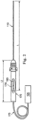
- Fig. 1 illustrates a cannulation system 100 according to one embodiment of the present disclosure.
- the cannulation system 100 includes a sensor wire 110 slidably disposed within a penetrating instrument 120, as well as a Doppler ultrasound system 125.
- the penetrating instrument 120 is shown in a cross-sectional view so that the sensor wire 110 can be seen inside the penetrating instrument 120.
- the Doppler ultrasound system 125 consists of a processor 130, an ultrasound pulse generator 135, a user input 138, and an indicating apparatus 140.
- the system 100 is arranged to facilitate the localization and penetration of an internal anatomic structure such as, by way of non-limiting example, a vessel.
- the individual component parts of the cannulation system 100 may be electrically, optically, and/or wirelessly connected to facilitate the transfer of power, signals, and/or data.
- the number and location of the components depicted in Fig. 1 are not intended to limit the present disclosure, and are merely provided to illustrate an environment in which the devices and methods described herein may be used.
- the sensor wire 110 is shaped and configured as an elongate, rigid, cylindrical tube.
- the sensor wire 110 includes a hollow elongate tube 145, a sensor 150, and a core wire 155.
- a core wire 155 extends between a proximal portion 160 and a distal portion 165 of the sensor wire 110.
- the sensor 150 is coupled to the core wire 155 at the distal portion 165.
- the sensor 150 may be attached to the core wire 155 or tube 145 in any of a variety of coupling mechanisms, including by way of non-limiting example, a snap-fit engagement, adhesive, welding, pressure fit, and/or mechanical fasteners.
- the senor 150 is attached to the core wire 155 via welding and a housing around the sensor is bonded to the tube 145 via an adhesive.
- the sensor housing is directly attached to a rigid hollow elongate tube 145 and the core wire can be omitted, thereby forming a rigid sensor wire assembly.
- the sensor wire 110 will be described in further detail below with reference to Figs. 4 and 5 .
- the sensor wire 110 is coupled to the Doppler ultrasound system 125 in any of a variety of means known to those skilled in the art.
- the proximal portion 160 of the sensor wire 110 is coupled via a connector 170 to a supply cable 175 linked to the Doppler ultrasound system 125.
- the connector 170 has an inner passage 176 which can house the proximal portion 160 of the sensor wire 110.
- the sensor wire 110 may be selectively coupled to the connector 170 and the supply cable 175 in any of a variety of selective coupling mechanisms, including by way of non-limiting example, a threaded engagement, a snap-fit engagement, and a tension-based engagement.
- the connector 170 comprises a handle sized such that it may be held and maneuvered by a user during a medical procedure.
- the connector is a conventional releasable connector utilized with coronary sensing systems sold by Volcano Corporation under the trade name ComboWire ® .
- the sensor wire 110 possesses sufficient column strength to support the weight of the connector 170 without causing damage to or deformation of the sensor wire 110.
- the connector 170 can be disconnected to allow the advancement of a surgical instrument, such as, by way of non-limiting example, a balloon catheter, an irrigation catheter, an imaging catheter, another suitable surgical catheter, another sensor wire, or a guidewire, over the sensor wire 110 or in place of the sensor wire 110.
- the sensor wire and the connector include similar features to and interact in ways similar to those disclosed for the guidewire and connector, respectively, in U.S. Patent No. 8,231,537, entitled “Combination Sensor Guidewire and Methods of Use” and filed on June 23, 2006 .
- the penetrating instrument 120 comprises an elongate, rigid tube.
- the penetrating instrument 120 includes a lumen 178 extending between a sharp distal tip 180 and a proximal end 185.
- the sharp distal tip 180 is shaped and configured to penetrate the skin, subcutaneous tissue, and other anatomic tissues of the patient (e.g., a vessel wall).
- the penetrating instrument 120 comprises a surgical needle.
- the penetrating instrument may comprise a surgical introducer, which can be sized and shaped to allow the passage of the sensor wire 110 and/or other surgical instruments from the proximal end through the distal end.
- a surgical introducer which can be sized and shaped to allow the passage of the sensor wire 110 and/or other surgical instruments from the proximal end through the distal end.
- the penetrating instrument may comprise the combination of a surgical introducer and a surgical needle, wherein the introducer is sized and shaped to allow the passage of the needle from a proximal end through a distal end, the needle is inserted into a lumen of the introducer, and the sensor wire is inserted into the needle.
- the penetrating instrument 120 may range in an outer diameter D1 from 0.014 in (0.356 mm) to 0.040 in (1.016 mm).
- a wall thickness T of the penetrating instrument 120 may range from 0.001 to 0.004 inches. In one embodiment, the wall thickness T of the penetrating instrument is 0.002 in (0.051 mm).
- the penetrating instrument 120 may be a conventional 20 gauge surgical needle. In another embodiment, the penetrating instrument may be a conventional 22 gauge surgical needle.
- the sensor wire 110 extends through the lumen 178 of the penetrating instrument 120.
- the sensor wire 110 is shaped such that it can be slidably disposed within the lumen 178, and the sensor wire 110 is sized such that the distal portion 165 can extend beyond the distal tip 180 of the penetrating instrument 120.
- the sensor wire 110 is sized to be longer than the penetrating instrument 120.
- the diameter of the sensor wire 120 is sized to be less than the diameter of the lumen 178 of the penetrating instrument 120 to enable the sensor wire 110 to be reciprocally and axially moveable within the penetrating instrument 120.
- the penetrating instrument 120 and the sensor wire 110 are sized such that an outer diameter D2 of the sensor wire 110 is substantially equal to or less than an inner diameter D3 of the lumen 178 of the penetrating instrument 120.
- the sensor wire 110 may range in diameter D2 from 0.008 in (0.203 mm) to 0.040 in (1.016 mm).
- the sensor wire 110 may have any of a variety of diameters D2, including, by way of non-limiting example, 0.010 in (0.254 mm), 0.014 in (0.356 mm), and 0.035 in (0.889 mm).
- the penetrating instrument 120 may range in inner diameter D3 from 10 to 30 gauge.
- the penetrating instrument 120 may have any of a variety of inner diameters D3, including, by way of non-limiting example, 0.010 in (0.254 mm).
- the sensor wire 110 may range in length L from 50 mm to 500 mm.
- the sensor wire 110 may have any of a variety of lengths, including, by way of non-limiting example, 25 cm.
- connection assembly is significantly smaller in diameter in relation to the overall length.
- the length of the sensor wire 110 is greater than 100 times longer than the diameter of the communication connection assembly 113. In one example, it has about a 250:1 length to diameter ratio.
- the overall ratio of length to diameter is less than 1000:1 in the illustrated examples.
- the length of the overall sensor wire 110 is less than 10 times longer than the length of the communication connection assembly 113.
- the sensor wire 110 can have a length of approximately 25 cm while the connection assembly 113 has a length L3 of approximately 3 cm.
- the connector 170 is illustrated attached to a sensing wire 110.
- the connector 170 has a length L2.
- L2 is about 5-15 cm in length.
- L2 is 8-10 cm in length.
- the connector can range in lengths and orientation.
- the sensor wire 110 may be entirely removed in the proximal direction from the penetrating instrument 120.
- the penetrating instrument 120 may be entirely removed in the proximal direction from around the sensor wire 110.
- the connector 170 may be disconnected from the sensor wire 110 to allow the removal of the penetrating instrument 120 in the proximal direction.
- the outer diameter D2 of the sensor wire 110 closely approximates the inner diameter D3 of the lumen 178 of the penetrating instrument 120, such that the sensor wire 110 can block undesired aspiration of bodily fluids and/or other substances into the lumen 178 of the penetrating instrument 120 during a procedure.
- the outer diameter D2 of the sensor wire 110 is less than the inner diameter D3 of the lumen 178 of the penetrating instrument 120, other means for blocking such undesired aspiration may be used.
- the penetrating instrument includes a seal, such as, by way of non-limiting example, an O-ring, at the distal tip 180 to prevent or minimize the entry of such tissues and fluids into the lumen 178 as the penetrating instrument is advanced to the target vessel.
- the penetrating instrument includes a conventional "bleed-back" chamber or valve.
- the penetrating instrument is coupled to a Tuohy-Borst adapter to prevent backflow of fluid during insertion into a patient.
- the penetrating instrument 120 includes a retaining feature 189 within the lumen 178 that prevents the sensor wire 110 from advancing a certain distance past the distal tip 180 and may selectively lock the sensor wire into position within the penetrating instrument.
- the retaining feature 189 extends circumferentially around the inner lumen 178.
- the retaining feature 189 may comprise any of a variety of retaining mechanisms, including, by way of non-limiting example, a flexible O-ring, a mechanical coupling, and or an adhesive such as "soft glue.”
- the retaining feature 189 serves to center and/or align the sensor wire 110 with the distal tip 180 of the penetrating instrument 120.
- Other embodiments may have any number of retaining features. Some embodiments lack a retaining feature.
- the Doppler ultrasound system 125 is configured for receiving, processing, and analyzing Doppler ultrasound data in accordance with one embodiment of the present disclosure.
- the Doppler ultrasound system 125 includes the processor 130, which is coupled to the ultrasound pulse generator 135 and the indicating apparatus 140.
- the Doppler ultrasound system 125 is coupled to the sensor wire 110, which carries the sensor 150.
- the sensor 150 comprises a Doppler ultrasound transducer.
- the sensor 150 may comprise an array of transducers.
- the processor 130 may include one or more programmable processor units running programmable code instructions for implementing the methods described herein, among other functions.
- the processor 130 may be integrated within a computer and/or other types of processor-based devices suitable for a variety of medical applications.
- the processor 130 can receive input data from the sensor wire 110 and/or the ultrasound pulse generator 135 directly via wireless mechanisms or from wired connections such as the supply cable 175.
- the processor 130 may use such input data to generate control signals to control or direct the operation of the sensor wire 110.
- the user can program or direct the operation of the sensor wire 110 and/or the ultrasound pulse generator 135 from the user input 138.
- the processor 130 is in direct wireless communication with the sensor wire 110, the ultrasound pulse generator 135, and/or the user input 138, and can receive data from and send commands to the sensor wire 110, the ultrasound pulse generator 135, and/or the user input 138.
- processor 130 is a targeted device controller that may be connected to a power source (not shown), accessory devices (such as, by way of non-limiting example, the indicating apparatus 140), and/or a memory (not shown).
- the processor 130 is in communication with and performs specific control functions targeted to a specific device or component of the system 100, such as the sensor wire 110 and/or the ultrasound pulse generator 135, without utilizing input from the user input 138.
- the processor 130 may direct or program the sensor wire 110 and/or the ultrasound pulse generator 135 to function for a specified period of time, at a particular frequency, and/or at a particular angle of incidence without specific user input.
- the processor 130 is programmable so that it can function to simultaneously control and communicate with more than one component of the system 100.
- the system 100 includes more than one processor and each processor is a special purpose controller configured to control individual components of the system.
- the processor 130 is configured to acquire Doppler ultrasound data from a blood vessel through the sensor wire 110, and can analyze the data to determine the presence or absence and direction of fluid flow (e.g., blood flow) in front of the penetrating instrument 120.
- Doppler ultrasound measures the movement of objects through the emitted beam as a phase change in the received signal.
- a moving structure e.g., a red blood cell within a vessel
- the wavelength and the frequency of the returning waves are shifted. If the moving structure is moving toward the transducer, the frequency increases. If the moving structure is moving away from the transducer, the frequency decreases.
- the processor 130 is connected to the ultrasound pulse generator 135, and may control the ultrasound pulse generator.
- the ultrasound pulse generator 135 may comprise an ultrasound excitation or waveform generator that provides control signals (e.g., in the form of electric pulses) to the sensor wire 110 to control the ultrasound wave output from the sensor 150.
- control signals e.g., in the form of electric pulses
- the ultrasound pulse generator 135 directs continuous wave ultrasound from the sensor 150, instead of pulsed wave ultrasound.
- the ultrasound generator is part of the processor 130. In other instances, the ultrasound generator is integrated in the sensor wire 110.
- the processor 130 is connected to the indicating apparatus 140, which is configured to convey information, including for example Doppler shift information gathered from the sensor wire 110, to the user.
- the processor 130 creates an appropriate indication to display via the indicating apparatus 140.
- the indicating apparatus 140 may be an oscillator or an auditory device configured to convey information to the user via auditory methods, such as meaningful tonality to convey different Doppler shift information.
- the indicating apparatus 140 may convey different Doppler shift information via tactile sensations, including by way of non-limiting example, vibration.
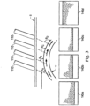
- the indicating apparatus 140 comprises a visual display configured to graphically or visually display the measured Doppler shifts to the user, and the average Doppler shift associated with different angles and/or positions of emitted energy is displayed visually.
- the indicating apparatus displays various sonograms associated with the different Doppler shifts observed as the sensor wire 110 is moved across the skin S, thereby emitting ultrasound waves at different angles of incidence ⁇ relative to the blood flow within the vessel V.
- a higher-frequency Doppler signal is shown on the indicating apparatus 140a because the emitted beam is aligned more with the direction of flow within the vessel V.
- a slightly lower-frequency Doppler signal is shown on the indicating apparatus 140b because the emitted beam is less aligned with the direction of flow within the vessel V.
- the Doppler shift information is displayed as color information superimposed on a background gray scale B mode ultrasound image.
- a positive Doppler shift is assigned one color and a negative Doppler shift is assigned another color.
- the magnitude of the Doppler shift is represented by the different gradients of brightness of the assigned color.
- the sensor wire 110 comprises the elongate tube 145, and the sensor assembly 148 including a pressure sensor 150 and an ultrasound transducer 210.
- the elongate tube 145 is shaped as a rigid, hollow cylinder having a lumen 190 with a circular cross-sectional shape.
- the sensor assembly 148 including the ultrasound sensor 210, are maintained in substantial alignment with the communication connection assembly 113 during use.
- the strength of the rigid elongate tube is sufficient to hold the weight of the female connector 170 along with the associated cable without substantially yielding from the longitudinal axis.
- the elongate tube may be semi-rigid and partially flexible and allow the connection assembly 113 to be longitudinally offset from the sensor assembly 148.
- the elongate tube can have any of a variety of cross-sectional shapes, including, for example, rectangular, square, or ovoid.
- the lumen 190 is shaped and sized to receive the core wire 155 and various electrical conductors 192 extending from the sensor assembly 148.
- the illustrated embodiment includes conductors extending to the pressure sensor 150 and conductors extending from the ultrasound transducer to the ultrasound energy supply (e.g., the supply cable 175 and the ultrasound pulse generator 135 (shown in Fig. 1 )).
- conductive bands 193 positioned at the proximal portion 160 of the sensor wire 110 forming a communication connection assembly 113.
- Various embodiments may include any number and arrangement of electrical conductors and conductive bands.
- Other embodiments may lack the electrical conductors 192 and/or the conductive bands 193.
- connection assembly 113 has a substantially uniform diameter with each conductive band axially spaced coaxially along the longitudinal axis with matching outer diameters.
- the outer diameter of the connection assembly 113 substantially matches the outer diameter of the elongated tube 145 and sensor assembly 148.
- the sensor wire has a uniform outer diameter along its entire length.
- the outer diameter may be 0.0014 or 0.0018 inches in two alternative embodiments.
- the elongate tube 145 may be composed of any of a variety of suitable biocompatible materials that are able to provide the desired amount of strength, rigidity, and corrosion resistance, including, by way of non-limiting example, Nitinol, stainless steel, titanium, nickel titanium alloys, cobalt alloys, combinations of tungsten/gold with stainless steel or cobalt alloys, alloys thereof, and polymers such as polyimide, polyetheretherketone (PEEK), polyamide, polyetherblockamide, polyethylene, polytetrafluoroethylene (PTFE), fluorinated ethylene propylene (FEP), and polyurethane.
- the elongate tube 145 possesses sufficient column strength and resilience to support the weight of the connector 170 (shown in Figs.
- the elongate tube 145 possesses a substantially constant degree of stiffness along its length.
- the sensor wire 110 has varying stiffness and flexibility along its length due to changes in material composition, thickness, and cross-sectional shape of the elongate tube 145.
- An outer wall 200 of the elongate tube 145 may range in thickness from 1 mm to 40 mm.
- the outer wall 200 may have any of a variety of thicknesses, including, by way of non-limiting example, 0.002 inches (0.051 mm).
- the outer wall 200 may be treated or coated with a material to give the sensor wire 110 a smooth outer surface with low friction.
- the sensor wire 110 is coated with a material along its length to ease insertion through the lumen 178 of the penetrating instrument 120.
- the entire length of sensor wire 110 or a portion of its length may be coated with a material that has lubricating or smoothing properties. Exemplary coatings can be hydrophobic or hydrophilic.
- Typical coatings may be formed from, by way of non-limiting example, polytetraflouroethylene (PTFE) or Teflon TM , a silicone fluid, or urethane-based polymers. Additionally or alternatively, other biocompatible coatings that provide the above mentioned properties could be used.
- PTFE polytetraflouroethylene
- Teflon TM Teflon TM
- silicone fluid silicone fluid
- urethane-based polymers urethane-based polymers
- the distal tip including the ultrasound transducer 210 is shaped and configured as a blunt, atraumatic tip.
- the distal tip 210 is shaped as a rounded, hemispherical dome.
- the distal tip may have any of a variety of atraumatic shapes, provided that the distal tip is configured to not penetrate the skin in the absence of undue pressure.
- the distal tip 210 may be sufficiently flexible to eliminate the need for the curve of the tip to be atraumatic.
- the distal tip can be sharp and/or have angular edges.
- the sensor 210 is shaped and configured to convey ultrasound energy along the longitudinal axis of the device through the distal tip.
- the sensor may be an ultrasound transducer configured to emit ultrasound waves and receive reflected ultrasound waves.
- the sensor may comprise a separate ultrasound transmitter and receiver, wherein the transmitter and receiver may be communicatively coupled to each other via either a wired or wireless link.
- the sensor is shown as a single transducer.
- the sensor may be any number of transducers, shaped in any of a variety of shapes and arranged in any of a variety of arrangements.
- the senor (and/or the sensor wire 110) includes additional amplifiers to achieve the desired sensitivity to the nature of the target fluid flow (e.g., blood flow and/or heart rate).
- the sensor depicted herein is not limited to any particular type of sensor, and includes all Doppler sensors and/or ultrasonic transducers known to those skilled in the art.
- a sensor wire having a single transducer adapted for rotation or oscillation, as well as a sensor wire having an array of transducers circumferentially positioned around the sensor wire are both within the content of the present disclosure.
- the Doppler sensor may include an optical sensor.
- the sensing wire includes a pressure sensor 150.
- the pressure sensor can be used to sense the pressure of blood within the blood vessel once the introducer is inserted. In the blood is not above a pre-determined pressure level, it may be an indicator that the introducer missed the vessel or entered a smaller vessel having too small of a diameter to receive the introducer.
- Fig. 5 illustrates the sensor wire 110 shown in Fig. 4 rotated at a different angle about the longitudinal axis LA.
- the sensor wire 110 is shown partially surrounded or encased by a sheath 300.
- the sensor wire 110 can be disposable in order to prevent the transfer of contagious diseases among different patients. In other embodiments, however, the sensor wire 110 may be reusable for performing medical procedures on different patients. If used with the sheath 300, for example, the sensor wire 110 can be reused on different patients because the probability of transferring a virus or bacterium among patients is reduced through the use of a disposable barrier such as the sheath 300. In other instances, the sensor wire 110 may be reused for procedures on different patients if it is sterilized between procedures.
- the elongated, flexible, protective sheath 300 extends from a proximal end 305 to a distal end 310.
- the proximal end 305 is open and relatively larger in diameter than the closed distal end 310.
- the sheath 300 is transparent, and, in particular, transparent to ultrasound energy.
- the sheath 300 is designed to encase the sensor housing 202 and at least a portion of the elongate tube 145.
- the inner diameter D4 of the sheath 300 is slightly larger than the outer diameter D2 of the sensor wire 110 (shown in Fig. 1 ).
- An outer diameter D5 of the sheath 300 is slightly smaller than the inner luminal diameter D3 of the penetrating instrument 120 (shown in Fig. 1 ).
- the sensor wire 110 even when encased within the sheath 300, can move back and forth along the longitudinal axis LA within the lumen 198 of the penetrating instrument 120 (shown in Fig. 1 ).
- Fig. 6 illustrates the sensor wire 110 disposed within the penetrating instrument 120 (e.g., prior to penetration of the skin S).
- the penetrating instrument 120 comprises a hollow bore needle.
- the user can advance the sensor wire 110 through the distal tip 180 of the penetrating instrument to position the sensor wire 110 against the skin S of a patient in the vicinity of a target vessel V.
- the distal end 210 of the sensor wire 110 is shaped and configured to emerge from the distal tip 180 of the penetrating instrument 120 to contact the skin S.
- the user can activate the Doppler ultrasound system 125 to transmit ultrasound waves 127 from the sensor 150 through the skin S towards the vessel V.
- the user may apply a liquid or gel material to the skin S to enhance the transmission and receipt of the ultrasound waves.
- the reflected signals obtained by the sensor 150 are communicated to the processor 130, which conveys the reflected data to the indicating apparatus 140 (shown in Fig. 1 ). If a Doppler shift is detected, the indicating apparatus 140 can convey the characteristics of the Doppler shift via an audible sound, a tactile sensation (e.g., a vibration), or a visual display.
- the reflected Doppler signal will be weak or nonexistent.
- the reflected data shown on the indicating apparatus will reveal that the penetrating instrument is not located at an optimal angle and position to penetrate the vessel V.
- the indicating apparatus 140 can indicate the direction of movement in which a user should move the penetrating instrument 120 to optimize the signal and locate the vessel V.
- Fig. 7 illustrates a side view of the sensor wire 110 disposed within the penetrating instrument 120 and positioned against the skin S at a more optimal angle to penetrate the vessel V.
- the indicating apparatus will continue to indicate the detected degree of Doppler shift.
- the penetrating instrument 120 is directed toward the vessel V, and in particular toward the direction of flow within the vessel V, the reflected Doppler signals will increase in intensity.
- the indicating apparatus 140 will reveal a Doppler shift indicating that the penetrating instrument 120 is located at an optimal angle and position to penetrate the vessel V.
- Fig. 8 illustrates a partially cross-sectional side view of the penetrating instrument 120 advancing into the vessel V while the sensor wire 110 remains outside the skin S according to one embodiment of the present disclosure.
- the user may manually prevent the sensor wire 110 from advancing with the penetrating instrument 120 by holding the sensor wire 110 in place proximal to the penetrating instrument 120 (e.g., by the connector 170 shown in Figs. 1 and 2 ).
- the sensor wire 110 may be temporarily restrained within the penetrating instrument by the connector 170 or by the retaining feature 189 within the lumen 178 of the penetrating instrument 120 (shown in Fig. 1 ).
- the sensor wire 110 may be retracted and/or removed from the penetrating instrument 120 as the penetrating instrument is advanced into the vessel V.
- Fig. 9 is a schematic representation of a side view of the sensor wire 110 encased in the sheath 300 and disposed within the penetrating instrument 120, wherein both the sensor wire and the penetrating instrument are advanced into the vessel V according to one embodiment of the present disclosure.
- the sensor wire 110 is inserted into the sheath 300 before being inserted into the penetrating instrument 120.
- the user can advance the sensor wire 110 and sheath 300 along with the penetrating instrument 120 into the vessel V without contaminating the sensor wire 110 (i.e., because the sheath 300 shields the sensor wire 110 from any tissue and fluid encountered within the patient).
- Actual penetration of the vessel V may be indicated by back flow of the blood into the penetrating instrument 120 and/or a bleedback chamber or valve. In some instances, actual penetration of the vessel V may be indicated by a stepped increase in the intensity of the reflected Doppler signal once the sensor wire 110 is within the vessel V. In such embodiments, if the sensor wire 110 is advanced into the vessel V, then the user can confirm the positioning of the penetrating instrument 120 within the vessel V before withdrawing the sensor wire 110 and sheath 300 from the patient.
- Fig. 10 illustrates a cross-sectional side view of the sensor wire 110 disposed within the penetrating instrument 120 and a delivery instrument 400, wherein the sensor wire 110 is positioned against the skin S of a patient according to one embodiment of the present disclosure.
- the penetrating instrument 120 comprises a hollow bore needle
- the delivery instrument 400 comprises a protective sheath surrounding the needle.
- the delivery instrument 400 extends from a tapered distal portion 405 to a slightly flared proximal portion 410.
- a distal tip 412 of the delivery instrument is sufficiently sharp to penetrate the skin S and the vessel V.
- the delivery instrument 400 may function as the penetrating instrument 120, and the user may forego the use of a separate penetrating instrument. Instead, the user may thread the sensor wire 110 directly into a lumen 415 of the delivery instrument 400.
- the distal tip 412 is blunt and atraumatic.
- the lumen 415 is sized and shaped to receive the penetrating instrument 120.
- the user can pass the penetrating instrument 120 into the lumen 415 of the delivery instrument 400 before introducing the sensor wire 110 into the lumen 178 of the penetrating instrument 120.
- the user can advance the sensor wire 110 through the distal tip 180 of the penetrating instrument (and the distal portion 405 of the delivery instrument 400) to position the sensor wire 110 against the skin S of a patient in the vicinity of a target vessel V.
- the distal end 210 of the sensor wire 110 is shaped and configured to emerge from the sharp distal tip 180 of the penetrating instrument 120 to contact the skin S.
- the user can activate the Doppler ultrasound system 125 to transmit ultrasound waves from the sensor 150 through the skin S towards the vessel V.
- the user may apply a liquid or gel material 420 to the skin S to enhance the transmission and receipt of the ultrasound waves.
- the reflected signals obtained by the sensor 150 are communicated to the processor 130, which conveys the reflected data to the indicating apparatus 140 (shown in Fig. 1 ). If a Doppler shift is detected, as described above in relation to Fig. 6 , the indicating apparatus 140 can convey the characteristics of the Doppler shift via an audible sound, a tactile sensation (e.g., a vibration), or a visual display.
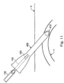
- Fig. 11 illustrates a cross-sectional side view of the delivery instrument 400 positioned within the vessel V while the penetrating instrument 120 and the sensor wire 110 are being withdrawn according to one embodiment of the present disclosure.
- the indicating apparatus 140 shows the user that the penetrating instrument 120 (and/or the delivery instrument 400) is optimally positioned to penetrate the vessel V
- the user can advance the penetrating instrument 120 and the delivery instrument 400 through the skin S and into the vessel V.
- the delivery instrument 400 may be left within the vessel V to enable the introduction of other medical devices into the vessel V, such as the elongated sensing wire 1200 shown in Fig. 2 .
- Fig. 12 illustrates an intravascular sensing wire 1200 connected to the connector assembly 170 of the sensing system.
- the sensing wire includes a distal sensor 1202 that can include one or more sensors such as pressure, flow, temperature or imaging.
- the communication connection assembly 1260 on the proximal portion is configured to substantially match the outer diameter and length of the connection assembly 160 of the shorter access sensing wire.
- the two connection assemblies are identical in the number of electrical connectors, the diameter of the connectors and their axial spacing along the axis. In this form, both sensing wires may be sequentially received within the female lumen 176 of the connector 170.
- either of the sensor wires may include a different number of conductive bands, however, the spacing between bands must match the spacing of electrical contacts within the connector lumen 176.
- the sensing wire 1200 is a very flexible wire suitable for passing through a tortuous vascular route and can typically have a length from 75-200 cm. In most embodiments, the sensing wire length will be at least 10 times the length L2 of the connector 170.
- the distal end of the elongated sensing wire 1200 can be passed through the delivery instrument into the vessel.
- the elongated sensing wire can then be advanced from the initial vessel segment into other vessel segments of the vasculature of the patient.
- the proximal connection assembly 1260 can then be inserted into the lumen 176 of the connector 170 and the distal barrel rotated to lock the connection assembly in place.
- the sensing system can be utilized in a conventional fashion with the processing system receiving signals, analyzing the signals and providing an output to the user based on the sensed signals.
- the intravascular sensor can detect pressure, flow, temperature, or image a vessel segment spaced up to the length of the sensing wire away from the delivery instrument.
- the cannulation system 100 which integrates the penetrating instrument 120 with the sensor wire 110 and the Doppler system 125, offers the user a faster and more accurate approach to vessel cannulation by allowing the user to accurately identify the optimal position and angle of penetration before puncturing the skin to access the target vessel.
- the system 100 not only enables the user to accurately penetrate the vessel without causing unnecessary damage to neighboring anatomic structures, but also enables the user to confirm the exact location of the penetrating instrument (and/or delivery instrument) within the vessel. Healthcare professionals will be able to access vessels much faster and more accurately using the system 100.
- the system can be particularly useful in patients having smaller or collapsed vessels (e.g., diabetic, elderly, pediatric, or obese patients).
Landscapes
- Health & Medical Sciences (AREA)
- Life Sciences & Earth Sciences (AREA)
- Surgery (AREA)
- Molecular Biology (AREA)
- Animal Behavior & Ethology (AREA)
- Nuclear Medicine, Radiotherapy & Molecular Imaging (AREA)
- Pathology (AREA)
- Veterinary Medicine (AREA)
- Engineering & Computer Science (AREA)
- Biomedical Technology (AREA)
- Heart & Thoracic Surgery (AREA)
- Medical Informatics (AREA)
- Public Health (AREA)
- General Health & Medical Sciences (AREA)
- Radiology & Medical Imaging (AREA)
- Physics & Mathematics (AREA)
- Biophysics (AREA)
- Vascular Medicine (AREA)
- Ultra Sonic Daignosis Equipment (AREA)
Description
- In this specification the following non-SI unit is used, which may be converted to the respective SI unit according to the following conversion table:
Name of unit Conversion factor SI or metric unit inch/inches 2.54 cm - During a variety of medical procedures, including vascular cannulation, it is desirable to intentionally penetrate certain internal anatomic structures to facilitate diagnostic and therapeutic objectives. However, accurate and efficient penetration may be difficult to accomplish, and may be accompanied by risks of inadvertently altering and/or harming neighboring structures.
- For example, a common procedure involving external to internal penetration of an anatomic structure is the localization and cannulation of vessels for inserting intravenous ("IV") tubes, drawing blood, or inserting an arterial catheter. However, health care practitioners may have difficulty in accurately locating the target vessel before advancing the delivery instrument or needle into the patient's tissue. Multiple placement attempts can result in discomfort to the patient and prolong the procedure time. In some instances, multiple placement attempts can damage neighboring structures such as nerves and other vessels. This problem is particularly pronounced in pediatric patients, obese patients, patients with unusual anatomy, and in acute care situations such as an emergency.
- Various devices and methods have been devised to help healthcare practitioners accurately locate a vessel prior to cannulation. For example, some methods employ Doppler sonar technology to determine the location and direction of the target vessel. However, several of these methods involve insertion of a needle into the patient's subcutaneous tissue before using Doppler to accurately locate the target vessel. The user employs a sweeping motion within the patient's tissue to locate the target vessel. Such a sweeping motion may be painful to the patient and cause injury to neighboring structures. Moreover, some ultrasonic placement devices require complicated catheter construction that incorporates ultrasonic transducers and receivers in the delivery instrument.
- For example,
US 4,887,606 A describes an apparatus for use in cannulation of blood vessels. The apparatus includes a hollow needle having a sharpened end for penetrating tissue, a trocar including a transducer mounted on one end for positioning within the hollow needle for transmitting and receiving ultrasonic waves through the sharpened end of the needle. As the needle is passed through the tissue, the tip of the needle is moved in a slight arc for directing ultrasound energy transmitted through the needle to the vessel. -
US 3,556,079 A describes a method of inserting a medical instrument under guidance of ultrasound, which is characterized by transmitting an ultrasonic beam toward the internal organs of the human body, receiving backscattered waves which have changed their frequency in accordance with the Doppler effect caused by the movement of a part of the internal organs, and utilizing the backscattered waves as a guide to insert a medical instrument such as a puncture needle so that the instrument can approach or reach or puncture the organ easily. -
US 5,779,642 A describes an interrogation device and specifically a Doppler-guided nerve stimulator device which accurately localizes and positions a puncture needle or other surgical probe into a neurovascular bundle or near a nerve. -
US 2003/060716 A1 describes a device for introducing an elastically bendable indwelling cannula together with an essentially rigid puncture cannula located therein into a blood vessel of a human or animal body. -
US 2002/0111620 A1 describes devices and methods of placement of such devices to altering gaseous flow within a lung to improve the expiration cycle of, for instance, an individual having Chronic Obstructive Pulmonary Disease. More particularly, these devices produce and maintain collateral openings or channels through the airway wall so that oxygen depleted/carbon dioxide rich air is able to pass directly out of the lung tissue. - The devices and systems disclosed herein overcome one or more of the deficiencies of the prior art.
- The invention is as defined in claim 1. Embodiments of the invention are defined by the dependent claims.
- In General, the present disclosure provides devices and systems for accessing and evaluating a vessel in a patient in a safe and accurate manner. The devices and systems can utilize Doppler ultrasound sensing to guide a user to the vessel and confirm positioning within the blood vessel. Once access to the vessel has been obtained in a safe and accurate manner, any number of alternative sensing devices can be introduced into the vessel for additional diagnosis and/or treatment.
- In one example (which no claim is directed at), a system for accessing and evaluating a blood vessel in a patient is provided. The system comprises an access sensor wire, an access needle sized to receive the access sensor wire, and a second sensing wire configured to be sequentially positioned within the access needle. In one feature, the access sensor wire includes a rigid member having a length generally equivalent to the length of the access needle while the second sensing wire is very flexible and several times longer than the access needle. An example (which no claim is directed at), provided for explanation, provides a method for utilizing a short access sensing wire to access a blood vessel with in an introduction needle with the short access sensing wire being replaced by a much longer second sensing wire after the needle is positioned in the vessel. In one embodiment, both the access sensing wire and second sensing wire having a substantially similar connection assembly.
- In another example (which no claim is directed at), a system for blood vessel access and sensing in a patient is provided. The system comprises a first access sensor wire having a hollow, elongate tube with a first length and first outer diameter, and a sensor disposed adjacent a distal portion of the tube configured to transmit and receive waves to detect Doppler shift. The system further includes a hollow penetrating instrument including a lumen defining a first inner diameter extending to a sharp distal end, the second lumen sized and shaped to receive the sensor wire. In one aspect, the system also includes a second sensor wire having a second length and a second outer diameter, wherein the second length is greater than two times the first length and the second outer diameter is substantially equal to the first diameter and configured for passing through the lumen of the hollow penetrating instrument. In one embodiment, the elongate tube is a rigid member.
- In another example (which no claim is directed at), a system for blood vessel access and sensing in a patient is provided including a connection mechanism for outputting sensor data to a processing system. In one aspect, the system includes a first access sensor wire having a hollow, elongate tube with a first length and first outer diameter configured for passing through a lumen of a hollow blood vessel penetrating instrument, and a sensor disposed adjacent a distal portion of the tube configured to transmit and receive waves to detect Doppler shift, the sensor in communication with a first connection assembly disposed adjacent a proximal portion of the tube. In a further aspect, the system includes a second sensor wire having a second length and a second outer diameter, wherein the second length is greater than two times the first length and the second outer diameter is substantially equal to the first diameter and configured for passing through the lumen of the hollow penetrating instrument, the second sensor wire having a second connection assembly disposed adjacent a proximal portion of the wire, the second connection assembly configured to substantially match the first connection assembly. The system may also include a female connector coupled to a signal processing system configured to analyze data from the sensor to detect a Doppler shift, the female connector having a lumen configured to receive each of the first connection assembly and second connection assembly sequentially. In one embodiment, the elongate tube is sufficiently rigid to maintain the connection assembly in alignment with the lumen of the hollow penetrating instrument when coupled to the female connector.
- In a further example (which no claim is directed at), provided for explanation, a method of accessing a vessel in a patient and sensing a parameter of a patient from within a connected vessel is provided. In an exemplary form, the method comprises connecting a sensor wire communication connection assembly to a female connector interconnected with a signal processing system; inserting the sensor wire into a lumen of a penetrating instrument, wherein the sensor wire includes a Doppler ultrasound transducer at a distal portion of the sensor wire, and wherein the penetrating instrument includes a sharp distal tip. The method continues by positioning the distal portion of the sensor wire adjacent the sharp distal tip of the penetrating instrument, positioning the distal portion of the sensor wire adjacent a skin surface of the patient, analyzing the Doppler shift of the reflected ultrasound data to evaluate the presence of a vessel in the tissue and the direction of flow within the vessel, moving the penetrating instrument and the sensor wire on the skin surface and analyzing the reflected ultrasound data until an optimal position and angle for penetrating the vessel is identified, and advancing the penetrating instrument into the skin surface and penetrating the vessel. Once the vessel has been accessed, then removing the access sensor wire from the penetrating instrument, connecting an internal sensor wire communication connection assembly to the female connector interconnected with the signal processing system, and inserting the internal sensor wire through the penetrating instrument into a blood vessel.
- In another example (which no claim is directed at), the present disclosure describes sensor wire that can be utilized within an introduction needle to identify blood vessels. In one embodiment, the sensor wire includes a rigid tubular body that can maintain the distal sensor in substantial alignment with the proximal communication connection assembly, even when carrying the weight of a female connector. In a further aspect, the sensing wire is relatively short in relation to its diameter. In still a further feature, the communication connection assembly has a length that is about 10 percent of the overall length of the sensing wire. In still a further feature, the sensing wire has a substantially uniform diameter from the distal sensor up to and including the communication connection assembly.
- In another exemplary embodiment, the present disclosure is directed to a device for locating a blood vessel in a patient. In one aspect, the device includes a hollow, elongate rigid tube including a lumen extending from a proximal portion to a distal portion, the tube having a longitudinal axis; an ultrasonic sensor coupled to the distal portion, the sensor configured to transmit and receive ultrasound waves distally along the longitudinal axis to detect Doppler shift; and at least one communication line extending from the sensor to a communication connection assembly positioned adjacent the proximal portion, wherein the rigid tube maintains the ultrasonic sensor and communication connection assembly in substantial alignment with the longitudinal axis during use.
- In a further exemplary embodiment (which no claim is directed at), the present disclosure is directed to a device for locating a blood vessel in a patient. The device comprises a sensor wire having a hollow, elongate tube including a lumen extending from a proximal portion to a distal portion, and having a length and a diameter wherein the length is less than 1000 times the diameter. The sensor wire includes an ultrasonic sensor positioned adjacent the distal portion and configured to transmit and receive ultrasound waves to detect Doppler shift and a communication connection assembly positioned adjacent the proximal portion. A further feature includes a hollow connector having a weight and configured to couple the sensor wire to a Doppler ultrasound processor, wherein the connector includes a second lumen sized to receive the communication connection assembly.
- In still a further exemplary embodiment (which no claim is directed at), the present disclosure provides a device for locating a blood vessel. The device includes a sensing wire tube having a first length extending along longitudinal axis and a diameter. The sensing wire includes a hollow, elongate tube including a lumen extending from a proximal portion to a distal portion, an ultrasonic sensor coupled to the distal portion, the sensor configured to transmit and receive ultrasound waves distally along the longitudinal axis to detect Doppler shift, and a least one communication line extending from the sensor to a communication connection assembly positioned adjacent the proximal portion. In at least one example, the connection assembly having a second length, wherein the ratio of the first length to the second length is less than 10 to 1. In still a further aspect, the sensor wire includes a pressure sensor for sensing blood pressure once the device is inserted into the body of a patient.
- It is to be understood that both the foregoing general description and the following detailed description are exemplary and explanatory in nature and are intended to provide an understanding of the present disclosure without limiting the scope of the present disclosure. In that regard, additional aspects, features, and advantages of the present disclosure will be apparent to one skilled in the art from the following detailed description.
- The accompanying drawings illustrate embodiments of the devices and examples of the methods disclosed herein and together with the description, serve to explain the principles of the present disclosure.
-
Fig. 1 is a schematic illustration of a cannulation system according to one embodiment of the present disclosure. -
Fig. 2 illustrates a partial cutaway side-view of a sensor wire coupled to a connector according to one embodiment of the present disclosure. -
Fig. 3 is a diagram illustrating various angles of emitted Doppler ultrasound toward a vessel and the corresponding sonograms that result on an indicating apparatus according to one embodiment of the present disclosure. -
Fig. 4 illustrates a partial cutaway side-view of a sensor wire according to one embodiment of the present disclosure. -
Fig. 5 illustrates a partial cutaway side-view of the sensor wire shown inFig. 4 at a different angle and positioned within a sheath according to one embodiment of the present disclosure. -
Fig. 6 is a schematic representation of a side view of the sensor wire disposed within the penetrating instrument and positioned against the skin of a patient according to one embodiment of the present disclosure. -
Fig. 7 is a schematic representation of a side view of the sensor wire disposed within the penetrating instrument and positioned against the skin of a patient in an optimal position to penetrate a vessel according to one embodiment of the present disclosure. -
Fig. 8 is a schematic representation of a partially cross-sectional side view of the penetrating instrument advancing into a vessel while the sensor remains outside the skin of a patient according to one embodiment of the present disclosure. -
Fig. 9 is a schematic representation of a side view of the sensor wire encased in a sheath and disposed within the penetrating instrument, wherein both the sensor wire and the penetrating instrument are advancing into a vessel of a patient according to one embodiment of the present disclosure. -
Fig. 10 is a schematic representation of a cross-sectional side view of the sensor wire disposed within the penetrating instrument and a delivery instrument, wherein the sensor wire is positioned against the skin of a patient according to one embodiment of the present disclosure. -
Fig. 11 is a schematic representation of a cross-sectional side view of the delivery instrument shown inFig. 10 positioned within a vessel of a patient while the penetrating instrument and the sensor wire are being withdrawn according to one embodiment of the present disclosure. -
Fig. 12 illustrates a partial cutaway side-view of an elongated sensor wire coupled to a connector according to one embodiment of the present disclosure. - For the purposes of promoting an understanding of the principles of the present disclosure, reference will now be made to the embodiments illustrated in the drawings, and specific language will be used to describe the same. It will nevertheless be understood that no limitation of the scope of the disclosure is intended. Any alterations and further modifications to the described devices, instruments, methods, and any further application of the principles of the present disclosure are fully contemplated as would normally occur to one skilled in the art to which the disclosure relates. In particular, for the sake of brevity, the various embodiments of prosthetic devices and corresponding engagement structures are described below with reference to particular exemplary combinations of components, features, and structures. However, it is understood that the various components, features, and structures of the exemplary embodiments are combinable in numerous other ways. It is fully contemplated that the features, components, and/or steps described with respect to one embodiment may be combined with the features, components, and/or steps described with respect to other embodiments of the present disclosure. Thus, features from one embodiment may be combined with features from another embodiment to form yet another embodiment of a device, system, or method according to the present disclosure even though such a combination is not explicitly shown. Further, for the sake of simplicity, in some instances the same reference numbers are used throughout the drawings to refer to the same or like parts.
- The present disclosure relates to devices, systems, and methods for accurately locating and penetrating anatomic structures using ultrasonic Doppler technology. More particularly, but not by way of limitation, the present disclosure relates to an ultrasonic sensor wire that is sized, shaped, and configured to pass through a penetrating instrument and transmit an ultrasound signal through the skin of the patient towards the region of a target vessel, thereby indicating the accurate location and direction of the target vessel. In addition, the present disclosure relates to a cannulation system comprising a sensor wire, a penetrating instrument, and a Doppler ultrasound system to allow the user to determine the location and direction of the target vessel in real time before and while advancing the penetrating instrument into the patient's body. Moreover, the present disclosure provides for a sensor wire that includes a protective sheath designed to prevent direct physical contact between the sensor wire and the patient, thereby allowing for the repeated use of the sensor wire in different patients.
- Because the sensor wire and system disclosed herein indicates the appropriate approach angle for penetration to the user before any actual penetration of tissue, the sensor wire enables the user to minimize inadvertent injury to neighboring tissue, such as, by way of non-limiting example, nerves, as the penetrating instrument travels toward the target structure.
- The various figures show embodiments of devices, systems, and methods suitable to accurately locate and penetrate a vessel within a patient. One of ordinary skill in the art, however, would understand that similar embodiments could be used to locate and penetrate other anatomic structures without departing from the general intent or teachings of the present disclosure, including, but not limited to, gastrointestinal organs, sinuses, respiratory tracts, genitourinary organs, and adjacent structures.
-
Fig. 1 illustrates acannulation system 100 according to one embodiment of the present disclosure. In the pictured embodiment, thecannulation system 100 includes asensor wire 110 slidably disposed within a penetratinginstrument 120, as well as aDoppler ultrasound system 125. The penetratinginstrument 120 is shown in a cross-sectional view so that thesensor wire 110 can be seen inside the penetratinginstrument 120. In the pictured embodiment, theDoppler ultrasound system 125 consists of aprocessor 130, anultrasound pulse generator 135, auser input 138, and an indicatingapparatus 140. Thesystem 100 is arranged to facilitate the localization and penetration of an internal anatomic structure such as, by way of non-limiting example, a vessel. The individual component parts of thecannulation system 100 may be electrically, optically, and/or wirelessly connected to facilitate the transfer of power, signals, and/or data. The number and location of the components depicted inFig. 1 are not intended to limit the present disclosure, and are merely provided to illustrate an environment in which the devices and methods described herein may be used. - In the illustrated embodiment, the
sensor wire 110 is shaped and configured as an elongate, rigid, cylindrical tube. Thesensor wire 110 includes a hollowelongate tube 145, asensor 150, and acore wire 155. In one aspect, acore wire 155 extends between aproximal portion 160 and adistal portion 165 of thesensor wire 110. In the pictured embodiment, thesensor 150 is coupled to thecore wire 155 at thedistal portion 165. Thesensor 150 may be attached to thecore wire 155 ortube 145 in any of a variety of coupling mechanisms, including by way of non-limiting example, a snap-fit engagement, adhesive, welding, pressure fit, and/or mechanical fasteners. In the pictured embodiment, thesensor 150 is attached to thecore wire 155 via welding and a housing around the sensor is bonded to thetube 145 via an adhesive. In a further embodiment, the sensor housing is directly attached to a rigid hollowelongate tube 145 and the core wire can be omitted, thereby forming a rigid sensor wire assembly. Thesensor wire 110 will be described in further detail below with reference toFigs. 4 and5 . - The
sensor wire 110 is coupled to theDoppler ultrasound system 125 in any of a variety of means known to those skilled in the art. In the pictured embodiment, theproximal portion 160 of thesensor wire 110 is coupled via aconnector 170 to asupply cable 175 linked to theDoppler ultrasound system 125. In some embodiments, as shown inFig. 2 , theconnector 170 has aninner passage 176 which can house theproximal portion 160 of thesensor wire 110. Thesensor wire 110 may be selectively coupled to theconnector 170 and thesupply cable 175 in any of a variety of selective coupling mechanisms, including by way of non-limiting example, a threaded engagement, a snap-fit engagement, and a tension-based engagement. In some embodiments, theconnector 170 comprises a handle sized such that it may be held and maneuvered by a user during a medical procedure. In the illustrated embodiment ofFig.2 , the connector is a conventional releasable connector utilized with coronary sensing systems sold by Volcano Corporation under the trade name ComboWire®. Thesensor wire 110 possesses sufficient column strength to support the weight of theconnector 170 without causing damage to or deformation of thesensor wire 110. In some embodiments, theconnector 170 can be disconnected to allow the advancement of a surgical instrument, such as, by way of non-limiting example, a balloon catheter, an irrigation catheter, an imaging catheter, another suitable surgical catheter, another sensor wire, or a guidewire, over thesensor wire 110 or in place of thesensor wire 110. In some instances, the sensor wire and the connector include similar features to and interact in ways similar to those disclosed for the guidewire and connector, respectively, inU.S. Patent No. 8,231,537, entitled "Combination Sensor Guidewire and Methods of Use" and filed on June 23, 2006 . - With reference to
Fig. 1 , the penetratinginstrument 120 comprises an elongate, rigid tube. The penetratinginstrument 120 includes alumen 178 extending between a sharpdistal tip 180 and aproximal end 185. The sharpdistal tip 180 is shaped and configured to penetrate the skin, subcutaneous tissue, and other anatomic tissues of the patient (e.g., a vessel wall). In the pictured embodiment, the penetratinginstrument 120 comprises a surgical needle. In other embodiments, the penetrating instrument may comprise a surgical introducer, which can be sized and shaped to allow the passage of thesensor wire 110 and/or other surgical instruments from the proximal end through the distal end. In other embodiments, as described below with reference toFig. 10 , the penetrating instrument may comprise the combination of a surgical introducer and a surgical needle, wherein the introducer is sized and shaped to allow the passage of the needle from a proximal end through a distal end, the needle is inserted into a lumen of the introducer, and the sensor wire is inserted into the needle. - The penetrating
instrument 120 may range in an outer diameter D1 from 0.014 in (0.356 mm) to 0.040 in (1.016 mm). A wall thickness T of the penetratinginstrument 120 may range from 0.001 to 0.004 inches. In one embodiment, the wall thickness T of the penetrating instrument is 0.002 in (0.051 mm). In one embodiment, the penetratinginstrument 120 may be a conventional 20 gauge surgical needle. In another embodiment, the penetrating instrument may be a conventional 22 gauge surgical needle. - The
sensor wire 110 extends through thelumen 178 of the penetratinginstrument 120. Thesensor wire 110 is shaped such that it can be slidably disposed within thelumen 178, and thesensor wire 110 is sized such that thedistal portion 165 can extend beyond thedistal tip 180 of the penetratinginstrument 120. In other words, thesensor wire 110 is sized to be longer than the penetratinginstrument 120. In the pictured embodiment, the diameter of thesensor wire 120 is sized to be less than the diameter of thelumen 178 of the penetratinginstrument 120 to enable thesensor wire 110 to be reciprocally and axially moveable within the penetratinginstrument 120. In particular, the penetratinginstrument 120 and thesensor wire 110 are sized such that an outer diameter D2 of thesensor wire 110 is substantially equal to or less than an inner diameter D3 of thelumen 178 of the penetratinginstrument 120. This enables reciprocating movement of thesensor wire 110 along a longitudinal axis LA within thelumen 178 in directions designated byarrows sensor wire 110 may range in diameter D2 from 0.008 in (0.203 mm) to 0.040 in (1.016 mm). For example, thesensor wire 110 may have any of a variety of diameters D2, including, by way of non-limiting example, 0.010 in (0.254 mm), 0.014 in (0.356 mm), and 0.035 in (0.889 mm). The penetratinginstrument 120 may range in inner diameter D3 from 10 to 30 gauge. The penetratinginstrument 120 may have any of a variety of inner diameters D3, including, by way of non-limiting example, 0.010 in (0.254 mm). With reference toFig. 2 , thesensor wire 110 may range in length L from 50 mm to 500 mm. For example, thesensor wire 110 may have any of a variety of lengths, including, by way of non-limiting example, 25 cm. - In one aspect, the connection assembly is significantly smaller in diameter in relation to the overall length. For example, in the illustrated embodiment, the length of the
sensor wire 110 is greater than 100 times longer than the diameter of thecommunication connection assembly 113. In one example, it has about a 250:1 length to diameter ratio. The overall ratio of length to diameter is less than 1000:1 in the illustrated examples. - In another aspect, the length of the
overall sensor wire 110 is less than 10 times longer than the length of thecommunication connection assembly 113. For example, thesensor wire 110 can have a length of approximately 25 cm while theconnection assembly 113 has a length L3 of approximately 3 cm. - Referring to
Fig. 2 , theconnector 170 is illustrated attached to asensing wire 110. Theconnector 170 has a length L2. In one embodiment, L2 is about 5-15 cm in length. In still a further embodiment, L2 is 8-10 cm in length. The connector can range in lengths and orientation. - In some instances, the
sensor wire 110 may be entirely removed in the proximal direction from the penetratinginstrument 120. In other instances, the penetratinginstrument 120 may be entirely removed in the proximal direction from around thesensor wire 110. For example, in some embodiments, theconnector 170 may be disconnected from thesensor wire 110 to allow the removal of the penetratinginstrument 120 in the proximal direction. When the user pierces the skin of a patient and advances the penetratinginstrument 120 in order to reach the target vessel, the penetratinginstrument 120 will pass through various neighboring tissues and fluids that may enter thelumen 178. In some embodiments, the outer diameter D2 of thesensor wire 110 closely approximates the inner diameter D3 of thelumen 178 of the penetratinginstrument 120, such that thesensor wire 110 can block undesired aspiration of bodily fluids and/or other substances into thelumen 178 of the penetratinginstrument 120 during a procedure. In instances where the outer diameter D2 of thesensor wire 110 is less than the inner diameter D3 of thelumen 178 of the penetratinginstrument 120, other means for blocking such undesired aspiration may be used. For example, in some embodiments, the penetrating instrument includes a seal, such as, by way of non-limiting example, an O-ring, at thedistal tip 180 to prevent or minimize the entry of such tissues and fluids into thelumen 178 as the penetrating instrument is advanced to the target vessel. In some embodiments, the penetrating instrument includes a conventional "bleed-back" chamber or valve. In some embodiments, the penetrating instrument is coupled to a Tuohy-Borst adapter to prevent backflow of fluid during insertion into a patient. - In the pictured embodiment, the penetrating
instrument 120 includes a retainingfeature 189 within thelumen 178 that prevents thesensor wire 110 from advancing a certain distance past thedistal tip 180 and may selectively lock the sensor wire into position within the penetrating instrument. In some instances, the retainingfeature 189 extends circumferentially around theinner lumen 178. The retainingfeature 189 may comprise any of a variety of retaining mechanisms, including, by way of non-limiting example, a flexible O-ring, a mechanical coupling, and or an adhesive such as "soft glue." In some instances, the retainingfeature 189 serves to center and/or align thesensor wire 110 with thedistal tip 180 of the penetratinginstrument 120. Other embodiments may have any number of retaining features. Some embodiments lack a retaining feature. - The
Doppler ultrasound system 125 is configured for receiving, processing, and analyzing Doppler ultrasound data in accordance with one embodiment of the present disclosure. TheDoppler ultrasound system 125 includes theprocessor 130, which is coupled to theultrasound pulse generator 135 and the indicatingapparatus 140. TheDoppler ultrasound system 125 is coupled to thesensor wire 110, which carries thesensor 150. In the pictured embodiment, thesensor 150 comprises a Doppler ultrasound transducer. In some embodiments, thesensor 150 may comprise an array of transducers. - The
processor 130 may include one or more programmable processor units running programmable code instructions for implementing the methods described herein, among other functions. Theprocessor 130 may be integrated within a computer and/or other types of processor-based devices suitable for a variety of medical applications. Theprocessor 130 can receive input data from thesensor wire 110 and/or theultrasound pulse generator 135 directly via wireless mechanisms or from wired connections such as thesupply cable 175. Theprocessor 130 may use such input data to generate control signals to control or direct the operation of thesensor wire 110. In some embodiments, the user can program or direct the operation of thesensor wire 110 and/or theultrasound pulse generator 135 from theuser input 138. In some embodiments, theprocessor 130 is in direct wireless communication with thesensor wire 110, theultrasound pulse generator 135, and/or theuser input 138, and can receive data from and send commands to thesensor wire 110, theultrasound pulse generator 135, and/or theuser input 138. - In various embodiments,
processor 130 is a targeted device controller that may be connected to a power source (not shown), accessory devices (such as, by way of non-limiting example, the indicating apparatus 140), and/or a memory (not shown). In such a case, theprocessor 130 is in communication with and performs specific control functions targeted to a specific device or component of thesystem 100, such as thesensor wire 110 and/or theultrasound pulse generator 135, without utilizing input from theuser input 138. For example, theprocessor 130 may direct or program thesensor wire 110 and/or theultrasound pulse generator 135 to function for a specified period of time, at a particular frequency, and/or at a particular angle of incidence without specific user input. In some embodiments, theprocessor 130 is programmable so that it can function to simultaneously control and communicate with more than one component of thesystem 100. In other embodiments, thesystem 100 includes more than one processor and each processor is a special purpose controller configured to control individual components of the system. - The
processor 130 is configured to acquire Doppler ultrasound data from a blood vessel through thesensor wire 110, and can analyze the data to determine the presence or absence and direction of fluid flow (e.g., blood flow) in front of the penetratinginstrument 120. Doppler ultrasound measures the movement of objects through the emitted beam as a phase change in the received signal. When ultrasound waves are reflected from a moving structure (e.g., a red blood cell within a vessel), the wavelength and the frequency of the returning waves are shifted. If the moving structure is moving toward the transducer, the frequency increases. If the moving structure is moving away from the transducer, the frequency decreases. In some embodiments, theprocessor 130 employs the Doppler Equation Δf = (2f0VCos θ)/C, where Δf is the frequency shift, f0 is the frequency of the transmitted wave, V is the velocity of the reflecting object (e.g., a red blood cell), θ is the angle between the incident wave and the direction of the movement of the reflecting object (i.e., the angle of incidence), and C is the velocity of sound in the medium. The frequency shift is maximal if thesensor 150 is oriented parallel to the direction of the blood flow and the θ is zero degrees (cos 0 = 1). The frequency shift is absent if thesensor 150 is oriented perpendicular to the direction of the blood flow and the θ is 90 degrees (cos 90 = 0). Higher Doppler frequency shifts are obtained the velocity is increased, the incident wave is more aligned to the direction of blood flow, and/or if a higher frequency is emitted. - In the pictured embodiment, the
processor 130 is connected to theultrasound pulse generator 135, and may control the ultrasound pulse generator. Theultrasound pulse generator 135 may comprise an ultrasound excitation or waveform generator that provides control signals (e.g., in the form of electric pulses) to thesensor wire 110 to control the ultrasound wave output from thesensor 150. In some instances, theultrasound pulse generator 135 directs continuous wave ultrasound from thesensor 150, instead of pulsed wave ultrasound. In some instances, the ultrasound generator is part of theprocessor 130. In other instances, the ultrasound generator is integrated in thesensor wire 110. - In the pictured embodiment, the
processor 130 is connected to the indicatingapparatus 140, which is configured to convey information, including for example Doppler shift information gathered from thesensor wire 110, to the user. In some instances, theprocessor 130 creates an appropriate indication to display via the indicatingapparatus 140. In some instances, the indicatingapparatus 140 may be an oscillator or an auditory device configured to convey information to the user via auditory methods, such as meaningful tonality to convey different Doppler shift information. In other instances, the indicatingapparatus 140 may convey different Doppler shift information via tactile sensations, including by way of non-limiting example, vibration. According to the invention, as shown inFig. 3 , the indicatingapparatus 140 comprises a visual display configured to graphically or visually display the measured Doppler shifts to the user, and the average Doppler shift associated with different angles and/or positions of emitted energy is displayed visually. - In
Fig. 3 , the indicating apparatus displays various sonograms associated with the different Doppler shifts observed as thesensor wire 110 is moved across the skin S, thereby emitting ultrasound waves at different angles of incidence θ relative to the blood flow within the vessel V. At the angle of incidence θA, a higher-frequency Doppler signal is shown on the indicatingapparatus 140a because the emitted beam is aligned more with the direction of flow within the vessel V. At the angle of incidence θB, a slightly lower-frequency Doppler signal is shown on the indicatingapparatus 140b because the emitted beam is less aligned with the direction of flow within the vessel V. At the angle of incidence θC, a relatively poor Doppler signal is shown on the indicatingapparatus 140c because the emitted ultrasound waves interact with the blood at almost 90 degrees. At the angle of incidence θD, a negative Doppler signal is shown on the indicatingapparatus 140d because the blood is travelling away from the emitted ultrasound waves. In other embodiments, the Doppler shift information is displayed as color information superimposed on a background gray scale B mode ultrasound image. In some embodiments, a positive Doppler shift is assigned one color and a negative Doppler shift is assigned another color. In some embodiments, the magnitude of the Doppler shift is represented by the different gradients of brightness of the assigned color. - With reference to
Fig. 4 , as mentioned above, thesensor wire 110 comprises theelongate tube 145, and thesensor assembly 148 including apressure sensor 150 and anultrasound transducer 210. In the pictured embodiment, theelongate tube 145 is shaped as a rigid, hollow cylinder having alumen 190 with a circular cross-sectional shape. With the rigid elongate tube, thesensor assembly 148, including theultrasound sensor 210, are maintained in substantial alignment with thecommunication connection assembly 113 during use. The strength of the rigid elongate tube is sufficient to hold the weight of thefemale connector 170 along with the associated cable without substantially yielding from the longitudinal axis. However, in alternative embodiments, the elongate tube may be semi-rigid and partially flexible and allow theconnection assembly 113 to be longitudinally offset from thesensor assembly 148. In various embodiments, the elongate tube can have any of a variety of cross-sectional shapes, including, for example, rectangular, square, or ovoid. Thelumen 190 is shaped and sized to receive thecore wire 155 and variouselectrical conductors 192 extending from thesensor assembly 148. The illustrated embodiment includes conductors extending to thepressure sensor 150 and conductors extending from the ultrasound transducer to the ultrasound energy supply (e.g., thesupply cable 175 and the ultrasound pulse generator 135 (shown inFig. 1 )). Also depicted in the pictured embodiment areconductive bands 193 positioned at theproximal portion 160 of thesensor wire 110 forming acommunication connection assembly 113. Various embodiments may include any number and arrangement of electrical conductors and conductive bands. Other embodiments may lack theelectrical conductors 192 and/or theconductive bands 193. - As illustrated in
Fig. 4 , theconnection assembly 113 has a substantially uniform diameter with each conductive band axially spaced coaxially along the longitudinal axis with matching outer diameters. The outer diameter of theconnection assembly 113 substantially matches the outer diameter of theelongated tube 145 andsensor assembly 148. Thus, the sensor wire has a uniform outer diameter along its entire length. In addition to the alternatives set forth above, the outer diameter may be 0.0014 or 0.0018 inches in two alternative embodiments. - The
elongate tube 145 may be composed of any of a variety of suitable biocompatible materials that are able to provide the desired amount of strength, rigidity, and corrosion resistance, including, by way of non-limiting example, Nitinol, stainless steel, titanium, nickel titanium alloys, cobalt alloys, combinations of tungsten/gold with stainless steel or cobalt alloys, alloys thereof, and polymers such as polyimide, polyetheretherketone (PEEK), polyamide, polyetherblockamide, polyethylene, polytetrafluoroethylene (PTFE), fluorinated ethylene propylene (FEP), and polyurethane. In some instances, theelongate tube 145 possesses sufficient column strength and resilience to support the weight of the connector 170 (shown inFigs. 1 and2 ) without causing damage to or deformation of thesensor wire 110. In the pictured embodiment, theelongate tube 145 possesses a substantially constant degree of stiffness along its length. In some instances, thesensor wire 110 has varying stiffness and flexibility along its length due to changes in material composition, thickness, and cross-sectional shape of theelongate tube 145. - An
outer wall 200 of theelongate tube 145 may range in thickness from 1 mm to 40 mm. For example, theouter wall 200 may have any of a variety of thicknesses, including, by way of non-limiting example, 0.002 inches (0.051 mm). In some embodiments, theouter wall 200 may be treated or coated with a material to give the sensor wire 110 a smooth outer surface with low friction. In some embodiments, thesensor wire 110 is coated with a material along its length to ease insertion through thelumen 178 of the penetratinginstrument 120. For example, the entire length ofsensor wire 110 or a portion of its length may be coated with a material that has lubricating or smoothing properties. Exemplary coatings can be hydrophobic or hydrophilic. Typical coatings may be formed from, by way of non-limiting example, polytetraflouroethylene (PTFE) or Teflon™, a silicone fluid, or urethane-based polymers. Additionally or alternatively, other biocompatible coatings that provide the above mentioned properties could be used. - With reference to
Figs. 4 and5 , the distal tip including theultrasound transducer 210 is shaped and configured as a blunt, atraumatic tip. In the pictured embodiment, thedistal tip 210 is shaped as a rounded, hemispherical dome. In other embodiments, the distal tip may have any of a variety of atraumatic shapes, provided that the distal tip is configured to not penetrate the skin in the absence of undue pressure. In some embodiments, thedistal tip 210 may be sufficiently flexible to eliminate the need for the curve of the tip to be atraumatic. In some embodiments where penetration of the skin by thesensor wire 110 is desired, the distal tip can be sharp and/or have angular edges. - The
sensor 210 is shaped and configured to convey ultrasound energy along the longitudinal axis of the device through the distal tip. In particular, the sensor may be an ultrasound transducer configured to emit ultrasound waves and receive reflected ultrasound waves. In other embodiments, the sensor may comprise a separate ultrasound transmitter and receiver, wherein the transmitter and receiver may be communicatively coupled to each other via either a wired or wireless link. In the pictured embodiment, the sensor is shown as a single transducer. In alternative embodiments, the sensor may be any number of transducers, shaped in any of a variety of shapes and arranged in any of a variety of arrangements. In some embodiments, the sensor (and/or the sensor wire 110) includes additional amplifiers to achieve the desired sensitivity to the nature of the target fluid flow (e.g., blood flow and/or heart rate). It should also be appreciated that the sensor depicted herein is not limited to any particular type of sensor, and includes all Doppler sensors and/or ultrasonic transducers known to those skilled in the art. For example, a sensor wire having a single transducer adapted for rotation or oscillation, as well as a sensor wire having an array of transducers circumferentially positioned around the sensor wire are both within the content of the present disclosure. In addition, the Doppler sensor may include an optical sensor. - In the illustrated embodiment, the sensing wire includes a
pressure sensor 150. The pressure sensor can be used to sense the pressure of blood within the blood vessel once the introducer is inserted. In the blood is not above a pre-determined pressure level, it may be an indicator that the introducer missed the vessel or entered a smaller vessel having too small of a diameter to receive the introducer. -
Fig. 5 illustrates thesensor wire 110 shown inFig. 4 rotated at a different angle about the longitudinal axis LA. InFig. 5 , thesensor wire 110 is shown partially surrounded or encased by asheath 300. In some embodiments, thesensor wire 110 can be disposable in order to prevent the transfer of contagious diseases among different patients. In other embodiments, however, thesensor wire 110 may be reusable for performing medical procedures on different patients. If used with thesheath 300, for example, thesensor wire 110 can be reused on different patients because the probability of transferring a virus or bacterium among patients is reduced through the use of a disposable barrier such as thesheath 300. In other instances, thesensor wire 110 may be reused for procedures on different patients if it is sterilized between procedures. - In the pictured embodiment, the elongated, flexible,
protective sheath 300 extends from aproximal end 305 to adistal end 310. Theproximal end 305 is open and relatively larger in diameter than the closeddistal end 310. In the pictured embodiment, thesheath 300 is transparent, and, in particular, transparent to ultrasound energy. Thesheath 300 is designed to encase thesensor housing 202 and at least a portion of theelongate tube 145. In the pictured embodiment, the inner diameter D4 of thesheath 300 is slightly larger than the outer diameter D2 of the sensor wire 110 (shown inFig. 1 ). An outer diameter D5 of thesheath 300 is slightly smaller than the inner luminal diameter D3 of the penetrating instrument 120 (shown inFig. 1 ). Thus, thesensor wire 110, even when encased within thesheath 300, can move back and forth along the longitudinal axis LA within the lumen 198 of the penetrating instrument 120 (shown inFig. 1 ). -
Fig. 6 illustrates thesensor wire 110 disposed within the penetrating instrument 120 (e.g., prior to penetration of the skin S). In the pictured embodiment, the penetratinginstrument 120 comprises a hollow bore needle. After threading thesensor wire 110 through thelumen 178 of the penetratinginstrument 120, the user can advance thesensor wire 110 through thedistal tip 180 of the penetrating instrument to position thesensor wire 110 against the skin S of a patient in the vicinity of a target vessel V. As mentioned above, thedistal end 210 of thesensor wire 110 is shaped and configured to emerge from thedistal tip 180 of the penetratinginstrument 120 to contact the skin S. Once thesensor wire 110 is resting against the skin S, the user can activate theDoppler ultrasound system 125 to transmitultrasound waves 127 from thesensor 150 through the skin S towards the vessel V. In some embodiments, the user may apply a liquid or gel material to the skin S to enhance the transmission and receipt of the ultrasound waves. The reflected signals obtained by thesensor 150 are communicated to theprocessor 130, which conveys the reflected data to the indicating apparatus 140 (shown inFig. 1 ). If a Doppler shift is detected, the indicatingapparatus 140 can convey the characteristics of the Doppler shift via an audible sound, a tactile sensation (e.g., a vibration), or a visual display. If the penetrating instrument is not directed toward the vessel V, the reflected Doppler signal will be weak or nonexistent. InFig. 6 , the reflected data shown on the indicating apparatus will reveal that the penetrating instrument is not located at an optimal angle and position to penetrate the vessel V. In some embodiments, the indicatingapparatus 140 can indicate the direction of movement in which a user should move the penetratinginstrument 120 to optimize the signal and locate the vessel V. -
Fig. 7 illustrates a side view of thesensor wire 110 disposed within the penetratinginstrument 120 and positioned against the skin S at a more optimal angle to penetrate the vessel V. As the user moves the penetratinginstrument 120 andsensor wire 110 over the skin S and takes Doppler measurements, the indicating apparatus will continue to indicate the detected degree of Doppler shift. As the penetratinginstrument 120 is directed toward the vessel V, and in particular toward the direction of flow within the vessel V, the reflected Doppler signals will increase in intensity. For example, when the user has moved thesensor wire 110 to the position shown inFig. 7 , the indicatingapparatus 140 will reveal a Doppler shift indicating that the penetratinginstrument 120 is located at an optimal angle and position to penetrate the vessel V. -
Fig. 8 illustrates a partially cross-sectional side view of the penetratinginstrument 120 advancing into the vessel V while thesensor wire 110 remains outside the skin S according to one embodiment of the present disclosure. Once the indicatingapparatus 140 shows the user that the penetratinginstrument 120 is optimally positioned to penetrate the vessel V, the user can advance the penetratinginstrument 120 through the skin S and into the vessel V. Actual penetration of the vessel V may be indicated by back flow of the blood into the penetratinginstrument 120 and/or a bleedback chamber or valve. In the pictured embodiment, thesensor wire 110 remains at the skin surface as the penetratinginstrument 120 is advanced into the vessel V. In some embodiments, the user may manually prevent thesensor wire 110 from advancing with the penetratinginstrument 120 by holding thesensor wire 110 in place proximal to the penetrating instrument 120 (e.g., by theconnector 170 shown inFigs. 1 and2 ). In other embodiments, thesensor wire 110 may be temporarily restrained within the penetrating instrument by theconnector 170 or by the retainingfeature 189 within thelumen 178 of the penetrating instrument 120 (shown inFig. 1 ). In some embodiments, thesensor wire 110 may be retracted and/or removed from the penetratinginstrument 120 as the penetrating instrument is advanced into the vessel V. -
Fig. 9 is a schematic representation of a side view of thesensor wire 110 encased in thesheath 300 and disposed within the penetratinginstrument 120, wherein both the sensor wire and the penetrating instrument are advanced into the vessel V according to one embodiment of the present disclosure. In this instance, thesensor wire 110 is inserted into thesheath 300 before being inserted into the penetratinginstrument 120. The user can advance thesensor wire 110 andsheath 300 along with the penetratinginstrument 120 into the vessel V without contaminating the sensor wire 110 (i.e., because thesheath 300 shields thesensor wire 110 from any tissue and fluid encountered within the patient). Actual penetration of the vessel V may be indicated by back flow of the blood into the penetratinginstrument 120 and/or a bleedback chamber or valve. In some instances, actual penetration of the vessel V may be indicated by a stepped increase in the intensity of the reflected Doppler signal once thesensor wire 110 is within the vessel V. In such embodiments, if thesensor wire 110 is advanced into the vessel V, then the user can confirm the positioning of the penetratinginstrument 120 within the vessel V before withdrawing thesensor wire 110 andsheath 300 from the patient. -
Fig. 10 illustrates a cross-sectional side view of thesensor wire 110 disposed within the penetratinginstrument 120 and adelivery instrument 400, wherein thesensor wire 110 is positioned against the skin S of a patient according to one embodiment of the present disclosure. In the pictured embodiment, the penetratinginstrument 120 comprises a hollow bore needle, and thedelivery instrument 400 comprises a protective sheath surrounding the needle. Thedelivery instrument 400 extends from a tapereddistal portion 405 to a slightly flaredproximal portion 410. In some embodiments, adistal tip 412 of the delivery instrument is sufficiently sharp to penetrate the skin S and the vessel V. In such embodiments, thedelivery instrument 400 may function as the penetratinginstrument 120, and the user may forego the use of a separate penetrating instrument. Instead, the user may thread thesensor wire 110 directly into alumen 415 of thedelivery instrument 400. In other embodiments, thedistal tip 412 is blunt and atraumatic. Thelumen 415 is sized and shaped to receive the penetratinginstrument 120. - In the pictured embodiment, the user can pass the penetrating
instrument 120 into thelumen 415 of thedelivery instrument 400 before introducing thesensor wire 110 into thelumen 178 of the penetratinginstrument 120. After threading thesensor wire 110 through thelumen 178 of the penetratinginstrument 120, the user can advance thesensor wire 110 through thedistal tip 180 of the penetrating instrument (and thedistal portion 405 of the delivery instrument 400) to position thesensor wire 110 against the skin S of a patient in the vicinity of a target vessel V. As mentioned above, thedistal end 210 of thesensor wire 110 is shaped and configured to emerge from the sharpdistal tip 180 of the penetratinginstrument 120 to contact the skin S. - Once the
sensor wire 110 is resting against the skin S, the user can activate theDoppler ultrasound system 125 to transmit ultrasound waves from thesensor 150 through the skin S towards the vessel V. In some embodiments, the user may apply a liquid orgel material 420 to the skin S to enhance the transmission and receipt of the ultrasound waves. The reflected signals obtained by thesensor 150 are communicated to theprocessor 130, which conveys the reflected data to the indicating apparatus 140 (shown inFig. 1 ). If a Doppler shift is detected, as described above in relation toFig. 6 , the indicatingapparatus 140 can convey the characteristics of the Doppler shift via an audible sound, a tactile sensation (e.g., a vibration), or a visual display. -
Fig. 11 illustrates a cross-sectional side view of thedelivery instrument 400 positioned within the vessel V while the penetratinginstrument 120 and thesensor wire 110 are being withdrawn according to one embodiment of the present disclosure. Once the indicatingapparatus 140 shows the user that the penetrating instrument 120 (and/or the delivery instrument 400) is optimally positioned to penetrate the vessel V, the user can advance the penetratinginstrument 120 and thedelivery instrument 400 through the skin S and into the vessel V. After withdrawal of the penetratinginstrument 120 and thesensor wire 110, thedelivery instrument 400 may be left within the vessel V to enable the introduction of other medical devices into the vessel V, such as theelongated sensing wire 1200 shown inFig. 2 . -
Fig. 12 illustrates anintravascular sensing wire 1200 connected to theconnector assembly 170 of the sensing system. The sensing wire includes adistal sensor 1202 that can include one or more sensors such as pressure, flow, temperature or imaging. Thecommunication connection assembly 1260 on the proximal portion is configured to substantially match the outer diameter and length of theconnection assembly 160 of the shorter access sensing wire. In one embodiment the two connection assemblies are identical in the number of electrical connectors, the diameter of the connectors and their axial spacing along the axis. In this form, both sensing wires may be sequentially received within thefemale lumen 176 of theconnector 170. It is contemplated, that either of the sensor wires may include a different number of conductive bands, however, the spacing between bands must match the spacing of electrical contacts within theconnector lumen 176. Thesensing wire 1200 is a very flexible wire suitable for passing through a tortuous vascular route and can typically have a length from 75-200 cm. In most embodiments, the sensing wire length will be at least 10 times the length L2 of theconnector 170. - After the
delivery instrument 400 has been positioned within the vessel V and access sensing wire removed, the distal end of theelongated sensing wire 1200 can be passed through the delivery instrument into the vessel. The elongated sensing wire can then be advanced from the initial vessel segment into other vessel segments of the vasculature of the patient. Theproximal connection assembly 1260 can then be inserted into thelumen 176 of theconnector 170 and the distal barrel rotated to lock the connection assembly in place. The sensing system can be utilized in a conventional fashion with the processing system receiving signals, analyzing the signals and providing an output to the user based on the sensed signals. Depending on the type ofsensor 1202, the intravascular sensor can detect pressure, flow, temperature, or image a vessel segment spaced up to the length of the sensing wire away from the delivery instrument. - The
cannulation system 100, which integrates the penetratinginstrument 120 with thesensor wire 110 and theDoppler system 125, offers the user a faster and more accurate approach to vessel cannulation by allowing the user to accurately identify the optimal position and angle of penetration before puncturing the skin to access the target vessel. Thesystem 100 not only enables the user to accurately penetrate the vessel without causing unnecessary damage to neighboring anatomic structures, but also enables the user to confirm the exact location of the penetrating instrument (and/or delivery instrument) within the vessel. Healthcare professionals will be able to access vessels much faster and more accurately using thesystem 100. The system can be particularly useful in patients having smaller or collapsed vessels (e.g., diabetic, elderly, pediatric, or obese patients). - Persons of ordinary skill in the art will appreciate that the embodiments encompassed by the present disclosure are not limited to the particular exemplary embodiments described above. In that regard, although illustrative embodiments have been shown and described, a wide range of modification, change, and substitution is contemplated in the foregoing disclosure. It is understood that such variations may be made to the foregoing without departing from the claims of the present disclosure. Accordingly, it is appropriate that the appended claims be construed broadly and in a manner consistent with the present disclosure.
Claims (15)
- A system for locating a blood vessel in a patient and for penetrating the blood vessel, comprising:a sensor wire (110) having:a hollow, elongate rigid tube (145) including a lumen extending from a proximal portion to a distal portion, the tube having a longitudinal axis and being positionable at different angles relative to the blood vessel;an ultrasonic sensor (150) coupled to the distal portion, the sensor configured to transmit and receive ultrasound waves distally along the longitudinal axis to detect Doppler shift; andat least one communication line extending from the sensor to a communication connection assembly (113) positioned adjacent the proximal portion, wherein the rigid tube is configured to maintain the ultrasonic sensor and communication connection assembly in substantial alignment with the longitudinal axis during use;a processor (130) configured to:acquire Doppler ultrasound data from a blood vessel through the sensor wire (110);analyze the data to determine the presence or absence and direction of blood flow in front of the sensor wire (110);characterized in that the processor is further configured to:output to a visual display (140) the average Doppler shift associated with different angles and positions of the sensor wire with respect to the blood vessel of the patient; andindicate to a user an appropriate approach angle for penetration of the blood vessel before any actual penetration of tissue.
- The system of claim 1, wherein the elongate tube (145) is a rigid cylinder with a circular cross-sectional shape.
- The system of claim 1, further including electrical conductors in communication with the sensor extending through a lumen of the elongate tube.
- The system of claim 1, wherein the communication connection assembly (113) includes a plurality of conductive bands on the proximal portion of the elongate tube.
- The system of claim 1, wherein the elongate tube (145) has a substantially constant degree of stiffness from the proximal portion to the distal portion.
- The system of claim 1, wherein the elongate tube (145) and communication connection assembly (113) have a substantially uniform diameter.
- The system of claim 1, further including a sensor housing (202) shaped and configured to enclose the sensor, wherein the sensor housing is coupled to the distal portion of the elongate tube.
- The system of claim 7, wherein the sensor housing (202) includes a blunt, rounded distal tip.
- The system of claim 8, wherein the sensor (150) is coupled to a core wire adjacent to the distal tip.
- The system of claim 7, wherein the sensor housing (202) includes an ultrasonically-transparent aperture through which the sensor can transmit and receive ultrasound waves.
- The system of claim 7, wherein the sensor housing (202) comprises a steerable tip.
- The system of claim 7, wherein the sensor housing (202) includes a sharp distal tip.
- The system of claim 1, wherein the sensor (150) comprises at least one ultrasonic transducer.
- The system of claim 9, wherein the core wire is electrically conductive.
- The system of claim 7, further including a tapered flexible sheath shaped and configured to surround the sensor housing and at least the distal portion of the elongate tube, the sheath having a closed distal end and an open proximal end, and wherein the flexible sheath is transparent to ultrasound energy.
Applications Claiming Priority (3)
| Application Number | Priority Date | Filing Date | Title |
|---|---|---|---|
| US201261737022P | 2012-12-13 | 2012-12-13 | |
| US201261737040P | 2012-12-13 | 2012-12-13 | |
| PCT/US2013/074171 WO2014093374A1 (en) | 2012-12-13 | 2013-12-10 | Devices, systems, and methods for targeted cannulation |
Publications (3)
| Publication Number | Publication Date |
|---|---|
| EP2931132A1 EP2931132A1 (en) | 2015-10-21 |
| EP2931132A4 EP2931132A4 (en) | 2016-07-27 |
| EP2931132B1 true EP2931132B1 (en) | 2023-07-05 |
Family
ID=50931704
Family Applications (1)
| Application Number | Title | Priority Date | Filing Date |
|---|---|---|---|
| EP13863432.4A Active EP2931132B1 (en) | 2012-12-13 | 2013-12-10 | System for targeted cannulation |
Country Status (5)
| Country | Link |
|---|---|
| US (1) | US10238367B2 (en) |
| EP (1) | EP2931132B1 (en) |
| JP (1) | JP6322210B2 (en) |
| CA (1) | CA2894403A1 (en) |
| WO (1) | WO2014093374A1 (en) |
Cited By (2)
| Publication number | Priority date | Publication date | Assignee | Title |
|---|---|---|---|---|
| US11813484B2 (en) | 2018-11-28 | 2023-11-14 | Histosonics, Inc. | Histotripsy systems and methods |
| US11813485B2 (en) | 2020-01-28 | 2023-11-14 | The Regents Of The University Of Michigan | Systems and methods for histotripsy immunosensitization |
Families Citing this family (12)
| Publication number | Priority date | Publication date | Assignee | Title |
|---|---|---|---|---|
| WO2016149701A1 (en) | 2015-03-19 | 2016-09-22 | The Regents Of The University Of Michigan | System for analyzing tissue |
| US20160287223A1 (en) * | 2015-04-01 | 2016-10-06 | Boston Scientific Scimed, Inc. | Pulmonary biopsy devices |
| US11426196B2 (en) | 2015-12-18 | 2022-08-30 | Boston Scientific Scimed, Inc. | Illuminable needle devices, systems, and methods |
| WO2017147288A1 (en) * | 2016-02-25 | 2017-08-31 | Boston Scientific Scimed, Inc. | Systems and methods for improved tissue sampling |
| US11633176B2 (en) * | 2016-08-03 | 2023-04-25 | Boston Scientific Scimed Inc. | Positioning devices, methods, and systems |
| CN109618553B (en) * | 2016-10-12 | 2022-04-12 | 直观外科手术操作公司 | Surgical puncturing device insertion systems and related methods |
| US11464485B2 (en) | 2018-12-27 | 2022-10-11 | Avent, Inc. | Transducer-mounted needle assembly with improved electrical connection to power source |
| US11647980B2 (en) | 2018-12-27 | 2023-05-16 | Avent, Inc. | Methods for needle identification on an ultrasound display screen by determining a meta-frame rate of the data signals |
| CN110025366B (en) * | 2019-04-23 | 2020-10-27 | 深圳先进技术研究院 | Puncture ultrasonic guiding device and puncture ultrasonic guiding equipment |
| US11540776B2 (en) * | 2020-03-20 | 2023-01-03 | Xenter, Inc. | Catheter for imaging and measurement of pressure and other physiologic parameters |
| US20240131277A1 (en) * | 2022-10-21 | 2024-04-25 | Boston Scientific Scimed Inc. | Mixing and injection system including a tracking sensor |
| WO2024092250A1 (en) * | 2022-10-28 | 2024-05-02 | Boston Scientific Scimed, Inc. | Medical device with retractable sensor |
Citations (2)
| Publication number | Priority date | Publication date | Assignee | Title |
|---|---|---|---|---|
| WO2001010314A2 (en) * | 1999-08-05 | 2001-02-15 | Broncus Technologies, Inc. | Methods and devices for creating collateral channels in the lungs |
| US20020111620A1 (en) * | 2001-02-14 | 2002-08-15 | Broncus Technologies, Inc. | Devices and methods for maintaining collateral channels in tissue |
Family Cites Families (952)
| Publication number | Priority date | Publication date | Assignee | Title |
|---|---|---|---|---|
| US3301258A (en) | 1963-10-03 | 1967-01-31 | Medtronic Inc | Method and apparatus for treating varicose veins |
| US3556079A (en) | 1967-05-16 | 1971-01-19 | Haruo Omizo | Method of puncturing a medical instrument under guidance of ultrasound |
| JPS4830874B1 (en) * | 1967-05-29 | 1973-09-25 | ||
| US3617880A (en) | 1970-05-15 | 1971-11-02 | Northern Electric Co | Time domain reflectometer |
| US3789841A (en) | 1971-09-15 | 1974-02-05 | Becton Dickinson Co | Disposable guide wire |
| JPS584481Y2 (en) | 1973-06-23 | 1983-01-26 | オリンパス光学工業株式会社 | Naishikiyoushiyahenkankogakkei |
| US3841308A (en) | 1973-10-15 | 1974-10-15 | Medical Evaluation Devices & I | Distally valved catheter device |
| JPS5921495B2 (en) | 1977-12-15 | 1984-05-21 | 株式会社豊田中央研究所 | Capillary pressure gauge |
| US4344438A (en) | 1978-08-02 | 1982-08-17 | The United States Of America As Represented By The Department Of Health, Education And Welfare | Optical sensor of plasma constituents |
| US4398791A (en) | 1981-02-09 | 1983-08-16 | Litton Systems, Inc. | Single channel optical slip ring |
| US4432370A (en) | 1981-10-14 | 1984-02-21 | The Board Of Trustees Of The Leland Stanford Junior University | Method and means for minimally invasive angiography using mono-chromatized synchrotron radiation |
| US5041108A (en) | 1981-12-11 | 1991-08-20 | Pillco Limited Partnership | Method for laser treatment of body lumens |
| US4582067A (en) * | 1983-02-14 | 1986-04-15 | Washington Research Foundation | Method for endoscopic blood flow detection by the use of ultrasonic energy |
| US4864578A (en) | 1983-04-12 | 1989-09-05 | Coherent, Inc. | Scannable laser with integral wavemeter |
| US4577543A (en) | 1983-08-18 | 1986-03-25 | American Hospital Supply Corporation | Construction of a monolithic reinforced catheter with flexible portions |
| US4552554A (en) | 1984-06-25 | 1985-11-12 | Medi-Tech Incorporated | Introducing catheter |
| GB8417911D0 (en) | 1984-07-13 | 1984-08-15 | British Telecomm | Connecting waveguides |
| DE3442736A1 (en) | 1984-11-23 | 1986-06-05 | Tassilo Dr.med. 7800 Freiburg Bonzel | DILATATION CATHETER |
| US5188632A (en) | 1984-12-07 | 1993-02-23 | Advanced Interventional Systems, Inc. | Guidance and delivery system for high-energy pulsed laser light |
| US4682895A (en) | 1985-08-06 | 1987-07-28 | Texas A&M University | Fiber optic probe for quantification of colorimetric reactions |
| US4676980A (en) | 1985-09-23 | 1987-06-30 | The United States Of America As Represented By The Secretary Of The Department Of Health And Human Services | Target specific cross-linked heteroantibodies |
| US4733665C2 (en) | 1985-11-07 | 2002-01-29 | Expandable Grafts Partnership | Expandable intraluminal graft and method and apparatus for implanting an expandable intraluminal graft |
| US4834093A (en) | 1986-02-03 | 1989-05-30 | Littleford Phillip O | Dilation catheter and method |
| US4803639A (en) | 1986-02-25 | 1989-02-07 | General Electric Company | X-ray inspection system |
| US5000185A (en) | 1986-02-28 | 1991-03-19 | Cardiovascular Imaging Systems, Inc. | Method for intravascular two-dimensional ultrasonography and recanalization |
| US4794931A (en) | 1986-02-28 | 1989-01-03 | Cardiovascular Imaging Systems, Inc. | Catheter apparatus, system and method for intravascular two-dimensional ultrasonography |
| US4771774A (en) | 1986-02-28 | 1988-09-20 | Devices For Vascular Intervention, Inc. | Motor drive unit |
| US5040548A (en) | 1989-06-01 | 1991-08-20 | Yock Paul G | Angioplasty mehtod |
| US4821731A (en) | 1986-04-25 | 1989-04-18 | Intra-Sonix, Inc. | Acoustic image system and method |
| US4766386A (en) | 1986-05-23 | 1988-08-23 | Cabletron | Time domain reflectometer for measuring impedance discontinuities on a powered transmission line |
| US4800886A (en) | 1986-07-14 | 1989-01-31 | C. R. Bard, Inc. | Sensor for measuring the concentration of a gaseous component in a fluid by absorption |
| US4887606A (en) | 1986-09-18 | 1989-12-19 | Yock Paul G | Apparatus for use in cannulation of blood vessels |
| GB8629871D0 (en) | 1986-12-15 | 1987-01-28 | British Telecomm | Optical switch |
| US5174295A (en) | 1987-04-10 | 1992-12-29 | Cardiometrics, Inc. | Apparatus, system and method for measuring spatial average velocity and/or volumetric flow of blood in a vessel and screw joint for use therewith |
| US5163445A (en) | 1987-04-10 | 1992-11-17 | Cardiometrics, Inc. | Apparatus, system and method for measuring spatial average velocity and/or volumetric flow of blood in a vessel and screw joint for use therewith |
| US4824435A (en) | 1987-05-18 | 1989-04-25 | Thomas J. Fogarty | Instrument guidance system |
| JP2697822B2 (en) | 1987-05-25 | 1998-01-14 | オリンパス光学工業株式会社 | Endoscope objective lens |
| US4841977A (en) | 1987-05-26 | 1989-06-27 | Inter Therapy, Inc. | Ultra-thin acoustic transducer and balloon catheter using same in imaging array subassembly |
| US4917097A (en) | 1987-10-27 | 1990-04-17 | Endosonics Corporation | Apparatus and method for imaging small cavities |
| US4819740A (en) | 1987-11-16 | 1989-04-11 | Vulcan Iron Works Inc. | Vibratory hammer/extractor |
| US4830023A (en) | 1987-11-27 | 1989-05-16 | Medi-Tech, Incorporated | Medical guidewire |
| US4917085A (en) | 1987-12-14 | 1990-04-17 | Cordis Corporation | Drive cutting catheter having new and improved drive motor |
| US4948229A (en) | 1988-03-18 | 1990-08-14 | The United States Of America As Represented By The Secretary Of The Air Force | Optical switches using ferroelectric liquid crystals |
| US4951677A (en) | 1988-03-21 | 1990-08-28 | Prutech Research And Development Partnership Ii | Acoustic imaging catheter and the like |
| US4932419A (en) | 1988-03-21 | 1990-06-12 | Boston Scientific Corporation | Multi-filar, cross-wound coil for medical devices |
| US5372138A (en) | 1988-03-21 | 1994-12-13 | Boston Scientific Corporation | Acousting imaging catheters and the like |
| US4998972A (en) | 1988-04-28 | 1991-03-12 | Thomas J. Fogarty | Real time angioscopy imaging system |
| US4987412A (en) | 1988-08-25 | 1991-01-22 | The United States Of America As Represented By The United States Department Of Energy | Method and apparatus for the simultaneous display and correlation of independently generated images |
| US5240437A (en) | 1988-11-02 | 1993-08-31 | Cardiometrics, Inc. | Torqueable guide wire assembly with electrical functions, male and female connectors for use therewith and system and apparatus for utilizing the same |
| US5178159A (en) | 1988-11-02 | 1993-01-12 | Cardiometrics, Inc. | Torqueable guide wire assembly with electrical functions, male and female connectors rotatable with respect to one another |
| US5065769A (en) | 1988-11-23 | 1991-11-19 | Boston Scientific Corporation | Small diameter guidewires of multi-filar, cross-wound coils |
| US5431673A (en) | 1989-02-17 | 1995-07-11 | American Biomed, Inc. | Distal atherectomy catheter |
| US4928693A (en) | 1989-03-13 | 1990-05-29 | Schneider (Usa), Inc. | Pressure monitor catheter |
| US4932413A (en) | 1989-03-13 | 1990-06-12 | Schneider (Usa), Inc. | Guidewire exchange catheter |
| US5203779A (en) | 1989-03-17 | 1993-04-20 | Schott Glaswerke | Catheter system for vessel recanalization in the human body |
| US5120308A (en) | 1989-05-03 | 1992-06-09 | Progressive Angioplasty Systems, Inc. | Catheter with high tactile guide wire |
| US4969742A (en) | 1989-06-27 | 1990-11-13 | The Boeing Company | Integrated optic wavemeter |
| WO1991001156A1 (en) | 1989-07-20 | 1991-02-07 | Devices For Vascular Intervention, Inc. | Improved guide wire systems for intravascular catheters |
| US4993412A (en) | 1989-08-02 | 1991-02-19 | Eclipse Surgical Technologies, Inc. | Method and apparatus for removal of obstructive substance from body channels |
| US5226909A (en) | 1989-09-12 | 1993-07-13 | Devices For Vascular Intervention, Inc. | Atherectomy device having helical blade and blade guide |
| NL8902559A (en) | 1989-10-16 | 1991-05-16 | Du Med Bv | INTRA-LUMINAL DEVICE. |
| US5240003A (en) | 1989-10-16 | 1993-08-31 | Du-Med B.V. | Ultrasonic instrument with a micro motor having stator coils on a flexible circuit board |
| US5024234A (en) | 1989-10-17 | 1991-06-18 | Cardiovascular Imaging Systems, Inc. | Ultrasonic imaging catheter with guidewire channel |
| US5133035A (en) | 1989-11-14 | 1992-07-21 | Hicks John W | Multifiber endoscope with multiple scanning modes to produce an image free of fixed pattern noise |
| US5025445A (en) | 1989-11-22 | 1991-06-18 | Cymer Laser Technologies | System for, and method of, regulating the wavelength of a light beam |
| US5155439A (en) | 1989-12-12 | 1992-10-13 | Tektronix, Inc. | Method of detecting and characterizing anomalies in a propagative medium |
| US5135516A (en) | 1989-12-15 | 1992-08-04 | Boston Scientific Corporation | Lubricious antithrombogenic catheters, guidewires and coatings |
| US5032123A (en) | 1989-12-28 | 1991-07-16 | Cordis Corporation | Laser catheter with radially divergent treatment beam |
| US5313957A (en) | 1990-01-05 | 1994-05-24 | Medamicus, Inc. | Guide wire mounted pressure transducer |
| US5358478A (en) | 1990-02-02 | 1994-10-25 | Ep Technologies, Inc. | Catheter steering assembly providing asymmetric left and right curve configurations |
| US5396328A (en) | 1990-02-09 | 1995-03-07 | Dr. Johannes Heidenhain Gmbh | Waveguide type displacement interferometer having two reference paths |
| US5037169A (en) | 1990-02-20 | 1991-08-06 | Unisys Corporation | High speed low loss optical switch for optical communication systems |
| DE9016985U1 (en) | 1990-03-05 | 1991-03-07 | Schneider (Europe) Ag, Zuerich, Ch | |
| US5039193A (en) | 1990-04-03 | 1991-08-13 | Focal Technologies Incorporated | Fibre optic single mode rotary joint |
| US5158548A (en) | 1990-04-25 | 1992-10-27 | Advanced Cardiovascular Systems, Inc. | Method and system for stent delivery |
| US5095911A (en) | 1990-05-18 | 1992-03-17 | Cardiovascular Imaging Systems, Inc. | Guidewire with imaging capability |
| US5100424A (en) | 1990-05-21 | 1992-03-31 | Cardiovascular Imaging Systems, Inc. | Intravascular catheter having combined imaging abrasion head |
| US5674232A (en) | 1990-06-05 | 1997-10-07 | Halliburton; Alexander George | Catheter and method of use thereof |
| US5085221A (en) | 1990-06-14 | 1992-02-04 | Interspec, Inc. | Ultrasonic imaging probe |
| US5437778A (en) | 1990-07-10 | 1995-08-01 | Telic Technologies Corporation | Slotted cylindrical hollow cathode/magnetron sputtering device |
| US5520189A (en) | 1990-07-13 | 1996-05-28 | Coraje, Inc. | Intravascular ultrasound imaging guidewire |
| US5065010A (en) | 1990-08-30 | 1991-11-12 | Camino Laboratories | Fiber optic measurement system having a reference conductor for controlling the energy level of the light source |
| US5135486A (en) | 1990-08-31 | 1992-08-04 | Endosonics Corporation | Self-venting balloon dilitation catheter |
| US5125137A (en) | 1990-09-06 | 1992-06-30 | Cardiometrics, Inc. | Method for providing a miniature ultrasound high efficiency transducer assembly |
| US5266302A (en) | 1990-10-03 | 1993-11-30 | Peyman Gholam A | Method of performing angiography |
| US5242460A (en) | 1990-10-25 | 1993-09-07 | Devices For Vascular Intervention, Inc. | Atherectomy catheter having axially-disposed cutting edge |
| US5202745A (en) | 1990-11-07 | 1993-04-13 | Hewlett-Packard Company | Polarization independent optical coherence-domain reflectometry |
| US5054492A (en) | 1990-12-17 | 1991-10-08 | Cardiovascular Imaging Systems, Inc. | Ultrasonic imaging catheter having rotational image correlation |
| DE69127462T2 (en) | 1990-12-17 | 1998-04-02 | Cardiovascular Imaging Systems | VASCULAR CATHETER WITH A LOW PROFILE DISTAL END |
| US5167233A (en) | 1991-01-07 | 1992-12-01 | Endosonics Corporation | Dilating and imaging apparatus |
| US5267954A (en) | 1991-01-11 | 1993-12-07 | Baxter International Inc. | Ultra-sound catheter for removing obstructions from tubular anatomical structures such as blood vessels |
| US5243988A (en) | 1991-03-13 | 1993-09-14 | Scimed Life Systems, Inc. | Intravascular imaging apparatus and methods for use and manufacture |
| US5353798A (en) | 1991-03-13 | 1994-10-11 | Scimed Life Systems, Incorporated | Intravascular imaging apparatus and methods for use and manufacture |
| US5201316A (en) | 1991-03-18 | 1993-04-13 | Cardiovascular Imaging Systems, Inc. | Guide wire receptacle for catheters having rigid housings |
| US5454788A (en) | 1991-04-24 | 1995-10-03 | Baxter International Inc. | Exchangeable integrated-wire balloon catheter |
| US6111645A (en) | 1991-04-29 | 2000-08-29 | Massachusetts Institute Of Technology | Grating based phase control optical delay line |
| WO1992019930A1 (en) | 1991-04-29 | 1992-11-12 | Massachusetts Institute Of Technology | Method and apparatus for optical imaging and measurement |
| US6501551B1 (en) | 1991-04-29 | 2002-12-31 | Massachusetts Institute Of Technology | Fiber optic imaging endoscope interferometer with at least one faraday rotator |
| US6134003A (en) | 1991-04-29 | 2000-10-17 | Massachusetts Institute Of Technology | Method and apparatus for performing optical measurements using a fiber optic imaging guidewire, catheter or endoscope |
| DE4116789A1 (en) | 1991-05-23 | 1992-11-26 | Standard Elektrik Lorenz Ag | OPTICAL SWITCH |
| US5219335A (en) | 1991-05-23 | 1993-06-15 | Scimed Life Systems, Inc. | Intravascular device such as introducer sheath or balloon catheter or the like and methods for use thereof |
| US5183048A (en) | 1991-06-24 | 1993-02-02 | Endosonics Corporation | Method and apparatus for removing artifacts from an ultrasonically generated image of a small cavity |
| US5630806A (en) | 1991-08-13 | 1997-05-20 | Hudson International Conductors | Spiral wrapped medical tubing |
| US5377682A (en) | 1991-09-05 | 1995-01-03 | Matsushita Electric Industrial Co., Ltd. | Ultrasonic probe for transmission and reception of ultrasonic wave and ultrasonic diagnostic apparatus including ultrasonic probe |
| CA2117088A1 (en) | 1991-09-05 | 1993-03-18 | David R. Holmes | Flexible tubular device for use in medical applications |
| US5312361A (en) | 1991-09-13 | 1994-05-17 | Zadini Filiberto P | Automatic cannulation device |
| EP0605522B1 (en) | 1991-09-23 | 1999-06-23 | Medical Research Council | Methods for the production of humanized antibodies |
| US5565332A (en) | 1991-09-23 | 1996-10-15 | Medical Research Council | Production of chimeric antibodies - a combinatorial approach |
| US5500013A (en) | 1991-10-04 | 1996-03-19 | Scimed Life Systems, Inc. | Biodegradable drug delivery vascular stent |
| WO1993008829A1 (en) | 1991-11-04 | 1993-05-13 | The Regents Of The University Of California | Compositions that mediate killing of hiv-infected cells |
| US5596079A (en) | 1991-12-16 | 1997-01-21 | Smith; James R. | Mimetics of senescent cell derived inhibitors of DNA synthesis |
| US5259385A (en) * | 1991-12-23 | 1993-11-09 | Advanced Cardiovascular Systems, Inc. | Apparatus for the cannulation of blood vessels |
| US5631973A (en) | 1994-05-05 | 1997-05-20 | Sri International | Method for telemanipulation with telepresence |
| US5301001A (en) | 1992-02-12 | 1994-04-05 | Center For Innovative Technology | Extrinsic fiber optic displacement sensors and displacement sensing systems |
| US5405377A (en) | 1992-02-21 | 1995-04-11 | Endotech Ltd. | Intraluminal stent |
| ES2217685T3 (en) | 1992-02-21 | 2004-11-01 | Boston Scientific Limited | CATETER FOR THE REPRESENTATION OF PICTURES BY ULTRASOUND. |
| US5220922A (en) | 1992-03-05 | 1993-06-22 | Barany Laszlo P | Ultrasonic non-contact motion monitoring system |
| US5226421A (en) | 1992-03-06 | 1993-07-13 | Cardiometrics, Inc. | Doppler elongate flexible member having an inflatable balloon mounted thereon |
| US5224953A (en) | 1992-05-01 | 1993-07-06 | The Beth Israel Hospital Association | Method for treatment of obstructive portions of urinary passageways |
| US5713848A (en) | 1993-05-19 | 1998-02-03 | Dubrul; Will R. | Vibrating catheter |
| US5373845A (en) | 1992-05-22 | 1994-12-20 | Echo Cath, Ltd. | Apparatus and method for forward looking volume imaging |
| EP0597195B1 (en) | 1992-08-18 | 1999-07-21 | The Spectranetics Corporation | Fiber optic guide wire |
| US5257974A (en) | 1992-08-19 | 1993-11-02 | Scimed Life Systems, Inc. | Performance enhancement adaptor for intravascular balloon catheter |
| WO1994006460A1 (en) | 1992-09-21 | 1994-03-31 | Vitaphore Corporation | Embolization plugs for blood vessels |
| US6086581A (en) | 1992-09-29 | 2000-07-11 | Ep Technologies, Inc. | Large surface cardiac ablation catheter that assumes a low profile during introduction into the heart |
| US5336178A (en) | 1992-11-02 | 1994-08-09 | Localmed, Inc. | Intravascular catheter with infusion array |
| US5383853A (en) | 1992-11-12 | 1995-01-24 | Medtronic, Inc. | Rapid exchange catheter |
| US5311871A (en) * | 1993-01-12 | 1994-05-17 | Yock Paul G | Syringe with ultrasound emitting transducer for flow-directed cannulation of arteries and veins |
| US5373849A (en) | 1993-01-19 | 1994-12-20 | Cardiovascular Imaging Systems, Inc. | Forward viewing imaging catheter |
| US5348017A (en) | 1993-01-19 | 1994-09-20 | Cardiovascular Imaging Systems, Inc. | Drive shaft for an intravascular catheter system |
| US5368037A (en) | 1993-02-01 | 1994-11-29 | Endosonics Corporation | Ultrasound catheter |
| US5453575A (en) | 1993-02-01 | 1995-09-26 | Endosonics Corporation | Apparatus and method for detecting blood flow in intravascular ultrasonic imaging |
| DE69417465T2 (en) | 1993-02-05 | 1999-07-22 | Joe W And Dorothy Dorsett Brow | Ultrasound balloon catheter for angioplasty |
| US5325198A (en) | 1993-03-31 | 1994-06-28 | General Electric Company | Unitary transform methods of identifying defects in imaging devices |
| CH688538A5 (en) * | 1993-04-01 | 1997-11-14 | Armin Bollinger | Ultraschallortungsgeraet with Nadelfuehrung. |
| US5873835A (en) | 1993-04-29 | 1999-02-23 | Scimed Life Systems, Inc. | Intravascular pressure and flow sensor |
| US5309915A (en) * | 1993-06-07 | 1994-05-10 | Mte, Inc. | Apparatus for locating veins and arteries |
| US20020197456A1 (en) | 1993-06-30 | 2002-12-26 | Pope Edward J. A. | Integrated electro-luminescent biochip |
| JPH0719965A (en) | 1993-06-30 | 1995-01-20 | Ando Electric Co Ltd | Light wavemeter |
| US5581638A (en) | 1993-07-26 | 1996-12-03 | E-Systems, Inc. | Method for autonomous image registration |
| US5358409A (en) | 1993-08-31 | 1994-10-25 | Cardiometrics, Inc. | Rotary connector for flexible elongate member having electrical properties |
| US5348481A (en) | 1993-09-29 | 1994-09-20 | Cardiometrics, Inc. | Rotary connector for use with small diameter flexible elongate member having electrical capabilities |
| US5423806A (en) | 1993-10-01 | 1995-06-13 | Medtronic, Inc. | Laser extractor for an implanted object |
| US5427118A (en) | 1993-10-04 | 1995-06-27 | Baxter International Inc. | Ultrasonic guidewire |
| GB9320500D0 (en) | 1993-10-05 | 1993-11-24 | Rensihaw Plc | Interferometric distance measuring apparatus |
| EP0733233A4 (en) | 1993-12-12 | 1997-05-14 | Asp Solutions Usa Inc | Apparatus and method for signal processing |
| US5496997A (en) | 1994-01-03 | 1996-03-05 | Pope; Edward J. A. | Sensor incorporating an optical fiber and a solid porous inorganic microsphere |
| US5439139A (en) | 1994-01-31 | 1995-08-08 | Lanard Toys Limited | Toy water gun |
| US5538510A (en) | 1994-01-31 | 1996-07-23 | Cordis Corporation | Catheter having coextruded tubing |
| US5387193A (en) | 1994-02-09 | 1995-02-07 | Baxter International Inc. | Balloon dilation catheter with hypotube |
| US5411016A (en) | 1994-02-22 | 1995-05-02 | Scimed Life Systems, Inc. | Intravascular balloon catheter for use in combination with an angioscope |
| US5443457A (en) | 1994-02-24 | 1995-08-22 | Cardiovascular Imaging Systems, Incorporated | Tracking tip for a short lumen rapid exchange catheter |
| DE4408108A1 (en) | 1994-03-10 | 1995-09-14 | Bavaria Med Tech | Catheter for injecting a fluid or a drug |
| US5546717A (en) | 1994-04-20 | 1996-08-20 | Walker Systems, Inc. | Access floor trench raceway |
| US6139510A (en) | 1994-05-11 | 2000-10-31 | Target Therapeutics Inc. | Super elastic alloy guidewire |
| US5436759A (en) | 1994-06-14 | 1995-07-25 | The Regents Of The University Of California | Cross-talk free, low-noise optical amplifier |
| US5586054A (en) | 1994-07-08 | 1996-12-17 | Fluke Corporation | time-domain reflectometer for testing coaxial cables |
| US5397355A (en) | 1994-07-19 | 1995-03-14 | Stentco, Inc. | Intraluminal stent |
| WO1996007351A1 (en) | 1994-09-02 | 1996-03-14 | Cardiometrics, Inc. | Ultra miniature pressure sensor and guidewire using the same and method |
| US8025661B2 (en) | 1994-09-09 | 2011-09-27 | Cardiofocus, Inc. | Coaxial catheter instruments for ablation with radiant energy |
| US5606975A (en) | 1994-09-19 | 1997-03-04 | The Board Of Trustees Of The Leland Stanford Junior University | Forward viewing ultrasonic imaging catheter |
| US5667499A (en) | 1994-10-04 | 1997-09-16 | Scimed Life Systems, Inc. | Guide catheter unibody |
| US5507761A (en) | 1994-10-11 | 1996-04-16 | Duer; Edward Y. | Embolic cutting catheter |
| US5512044A (en) | 1994-10-11 | 1996-04-30 | Duer; Edward Y. | Embolic cutting catheter |
| US5492125A (en) | 1995-02-10 | 1996-02-20 | University Of Washington | Ultrasound signal processing apparatus |
| US6176842B1 (en) | 1995-03-08 | 2001-01-23 | Ekos Corporation | Ultrasound assembly for use with light activated drugs |
| US5485845A (en) | 1995-05-04 | 1996-01-23 | Hewlett Packard Company | Rotary encoder for intravascular ultrasound catheter |
| US5702892A (en) | 1995-05-09 | 1997-12-30 | The United States Of America As Represented By The Department Of Health And Human Services | Phage-display of immunoglobulin heavy chain libraries |
| US5592939A (en) | 1995-06-14 | 1997-01-14 | Martinelli; Michael A. | Method and system for navigating a catheter probe |
| US6059738A (en) | 1995-06-30 | 2000-05-09 | Meadox Medicals, Inc. | Guidewire having a coated tip |
| US5882722A (en) | 1995-07-12 | 1999-03-16 | Partnerships Limited, Inc. | Electrical conductors formed from mixtures of metal powders and metallo-organic decompositions compounds |
| US5598844A (en) | 1995-08-03 | 1997-02-04 | Cordis Corporation | Device for flushing a guidewire receiving lumen of a monorail or rapid exchange catheter |
| US6283951B1 (en) | 1996-10-11 | 2001-09-04 | Transvascular, Inc. | Systems and methods for delivering drugs to selected locations within the body |
| US6726677B1 (en) | 1995-10-13 | 2004-04-27 | Transvascular, Inc. | Stabilized tissue penetrating catheters |
| ATE275880T1 (en) | 1995-10-13 | 2004-10-15 | Transvascular Inc | DEVICE FOR BYPASSING ARTERIAL Narrowings AND/OR FOR PERFORMING OTHER TRANSVASCULAR PROCEDURES |
| KR19990064209A (en) | 1995-10-13 | 1999-07-26 | 트랜스바스큘라, 인코포레이티드 | Apparatus, Systems, and Methods for Interstitial Acupoint Intervention |
| US6375615B1 (en) | 1995-10-13 | 2002-04-23 | Transvascular, Inc. | Tissue penetrating catheters having integral imaging transducers and their methods of use |
| US5780958A (en) | 1995-11-03 | 1998-07-14 | Aura Systems, Inc. | Piezoelectric vibrating device |
| US5803083A (en) | 1995-11-09 | 1998-09-08 | Cordis Corporation | Guiding catheter with ultrasound imaging capability |
| US5749848A (en) | 1995-11-13 | 1998-05-12 | Cardiovascular Imaging Systems, Inc. | Catheter system having imaging, balloon angioplasty, and stent deployment capabilities, and method of use for guided stent deployment |
| US7226417B1 (en) | 1995-12-26 | 2007-06-05 | Volcano Corporation | High resolution intravascular ultrasound transducer assembly having a flexible substrate |
| US5779642A (en) | 1996-01-16 | 1998-07-14 | Nightengale; Christopher | Interrogation device and method |
| US5690642A (en) | 1996-01-18 | 1997-11-25 | Cook Incorporated | Rapid exchange stent delivery balloon catheter |
| US6031071A (en) | 1996-01-24 | 2000-02-29 | Biophage, Inc. | Methods of generating novel peptides |
| US6709444B1 (en) | 1996-02-02 | 2004-03-23 | Transvascular, Inc. | Methods for bypassing total or near-total obstructions in arteries or other anatomical conduits |
| CN1216930A (en) | 1996-02-02 | 1999-05-19 | 血管转换公司 | Device, system and method for interstitial transvascular intervention |
| US5771895A (en) | 1996-02-12 | 1998-06-30 | Slager; Cornelis J. | Catheter for obtaining three-dimensional reconstruction of a vascular lumen and wall |
| US5798521A (en) | 1996-02-27 | 1998-08-25 | The United States Of America As Represented By The Administrator Of The National Aeronautics And Space Administration | Apparatus and method for measuring strain in bragg gratings |
| US5830224A (en) | 1996-03-15 | 1998-11-03 | Beth Israel Deaconess Medical Center | Catheter apparatus and methodology for generating a fistula on-demand between closely associated blood vessels at a pre-chosen anatomic site in-vivo |
| US5672877A (en) | 1996-03-27 | 1997-09-30 | Adac Laboratories | Coregistration of multi-modality data in a medical imaging system |
| DE19615456A1 (en) | 1996-04-19 | 1997-10-23 | Philips Patentverwaltung | Process for the detection and correction of image distortions in computer tomography |
| GB9609866D0 (en) | 1996-05-11 | 1996-07-17 | Morgan John M | Ablation catheter |
| US5851464A (en) | 1996-05-13 | 1998-12-22 | Cordis Corporation | Method of making a fuseless soft tip catheter |
| US5951586A (en) | 1996-05-15 | 1999-09-14 | Medtronic, Inc. | Intraluminal stent |
| US6068623A (en) | 1997-03-06 | 2000-05-30 | Percusurge, Inc. | Hollow medical wires and methods of constructing same |
| US5916194A (en) | 1996-05-24 | 1999-06-29 | Sarcos, Inc. | Catheter/guide wire steering apparatus and method |
| GB2315020A (en) | 1996-07-11 | 1998-01-21 | Intravascular Res Ltd | Ultrasonic visualisation catheters |
| US5745634A (en) | 1996-07-24 | 1998-04-28 | Jds Fitel Inc. | Voltage controlled attenuator |
| WO1998012667A2 (en) | 1996-08-29 | 1998-03-26 | Johnson Steven A | Wavefield imaging using inverse scattering techniques |
| JPH1090603A (en) | 1996-09-18 | 1998-04-10 | Olympus Optical Co Ltd | Endscopic optical system |
| US5827313A (en) | 1996-09-27 | 1998-10-27 | Boston Scientific Corporation | Device for controlled longitudinal movement of an operative element within a catheter sheath and method |
| RU2132635C1 (en) | 1996-09-30 | 1999-07-10 | Алексеев Сергей Григорьевич | Method and device for diagnosing oncological diseases |
| US5800450A (en) | 1996-10-03 | 1998-09-01 | Interventional Technologies Inc. | Neovascularization catheter |
| US20050182297A1 (en) | 1996-10-04 | 2005-08-18 | Dietrich Gravenstein | Imaging scope |
| EP0835673A3 (en) | 1996-10-10 | 1998-09-23 | Schneider (Usa) Inc. | Catheter for tissue dilatation and drug delivery |
| US5848121A (en) | 1996-10-28 | 1998-12-08 | General Electric Company | Method and apparatus for digital subtraction angiography |
| US7591846B2 (en) | 1996-11-04 | 2009-09-22 | Boston Scientific Scimed, Inc. | Methods for deploying stents in bifurcations |
| US5872879A (en) | 1996-11-25 | 1999-02-16 | Boston Scientific Corporation | Rotatable connecting optical fibers |
| US5779731A (en) | 1996-12-20 | 1998-07-14 | Cordis Corporation | Balloon catheter having dual markers and method |
| US5857974A (en) | 1997-01-08 | 1999-01-12 | Endosonics Corporation | High resolution intravascular ultrasound transducer assembly having a flexible substrate |
| US6141089A (en) | 1997-01-16 | 2000-10-31 | Hewlett-Packard Company | Optical time domain reflectometer for measurements in optical networks with currently applied traffic signals |
| US6480285B1 (en) | 1997-01-28 | 2002-11-12 | Zetetic Institute | Multiple layer confocal interference microscopy using wavenumber domain reflectometry and background amplitude reduction and compensation |
| US5760901A (en) | 1997-01-28 | 1998-06-02 | Zetetic Institute | Method and apparatus for confocal interference microscopy with background amplitude reduction and compensation |
| WO1998038907A1 (en) | 1997-03-06 | 1998-09-11 | Massachusetts Institute Of Technology | Instrument for optically scanning of living tissue |
| US5921931A (en) | 1997-04-08 | 1999-07-13 | Endosonics Corporation | Method and apparatus for creating a color blood flow image based upon ultrasonic echo signals received by an intravascular ultrasound imaging probe |
| DE69706827T2 (en) | 1997-05-02 | 2002-03-28 | Agilent Technologies Inc | Wavelength measuring device and a device for regulating the wavelength of a light source |
| US5976120A (en) | 1997-05-05 | 1999-11-02 | Micro Therapeutics, Inc. | Single segment microcatheter |
| AU7711498A (en) | 1997-06-02 | 1998-12-21 | Joseph A. Izatt | Doppler flow imaging using optical coherence tomography |
| DE19731346C2 (en) | 1997-06-06 | 2003-09-25 | Lpkf Laser & Electronics Ag | Conductor structures and a method for their production |
| US6208415B1 (en) | 1997-06-12 | 2001-03-27 | The Regents Of The University Of California | Birefringence imaging in biological tissue using polarization sensitive optical coherent tomography |
| US6050944A (en) | 1997-06-17 | 2000-04-18 | Acuson Corporation | Method and apparatus for frequency control of an ultrasound system |
| US6102938A (en) | 1997-06-17 | 2000-08-15 | Medtronic Inc. | Endoluminal prosthetic bifurcation shunt |
| US6095976A (en) | 1997-06-19 | 2000-08-01 | Medinol Ltd. | Method for enhancing an image derived from reflected ultrasound signals produced by an ultrasound transmitter and detector inserted in a bodily lumen |
| US5925055A (en) | 1997-06-23 | 1999-07-20 | Medelex, Inc | Multimodal rotary abrasion and acoustic ablation catheter |
| US5978391A (en) | 1997-07-18 | 1999-11-02 | Cymer, Inc. | Wavelength reference for excimer laser |
| US6256090B1 (en) | 1997-07-31 | 2001-07-03 | University Of Maryland | Method and apparatus for determining the shape of a flexible body |
| EP1001701B1 (en) | 1997-08-09 | 2004-10-06 | Roche Diagnostics GmbH | Analytical device for in vivo analysis in the body of a patient |
| US6148095A (en) | 1997-09-08 | 2000-11-14 | University Of Iowa Research Foundation | Apparatus and method for determining three-dimensional representations of tortuous vessels |
| US6050949A (en) | 1997-09-22 | 2000-04-18 | Scimed Life Systems, Inc. | Catheher system having connectable distal and proximal portions |
| US6179809B1 (en) | 1997-09-24 | 2001-01-30 | Eclipse Surgical Technologies, Inc. | Drug delivery catheter with tip alignment |
| US5951480A (en) | 1997-09-29 | 1999-09-14 | Boston Scientific Corporation | Ultrasound imaging guidewire with static central core and tip |
| US6078831A (en) | 1997-09-29 | 2000-06-20 | Scimed Life Systems, Inc. | Intravascular imaging guidewire |
| DE69832408T2 (en) | 1997-09-29 | 2006-09-28 | Boston Scientific Ltd., St. Michael | GUIDANCE CATHETER FOR INTRAVASCULAR PICTURE GENERATION |
| US6343168B1 (en) | 1997-10-02 | 2002-01-29 | Luna Innovations, Inc. | Optical sensor arrangement |
| US6021240A (en) | 1997-10-02 | 2000-02-01 | F&S, Inc. | Optical sensor activation device |
| US6842639B1 (en) | 1997-10-03 | 2005-01-11 | Intraluminal Therapeutics, Inc. | Method and apparatus for determining neovascular flow through tissue in a vessel |
| US6099471A (en) | 1997-10-07 | 2000-08-08 | General Electric Company | Method and apparatus for real-time calculation and display of strain in ultrasound imaging |
| US6097755A (en) | 1997-10-20 | 2000-08-01 | Tektronix, Inc. | Time domain reflectometer having optimal interrogating pulses |
| US6183432B1 (en) | 1997-11-13 | 2001-02-06 | Lumend, Inc. | Guidewire and catheter with rotating and reciprocating symmetrical or asymmetrical distal tip |
| US5876344A (en) | 1997-12-09 | 1999-03-02 | Endosonics Corporation | Modular imaging/treatment catheter assembly and method |
| US6140740A (en) | 1997-12-30 | 2000-10-31 | Remon Medical Technologies, Ltd. | Piezoelectric transducer |
| US6085004A (en) | 1998-02-03 | 2000-07-04 | 3M Innovative Properties Company | Optical fiber connector using photocurable adhesive |
| US20060074442A1 (en) | 2000-04-06 | 2006-04-06 | Revascular Therapeutics, Inc. | Guidewire for crossing occlusions or stenoses |
| EP1059878B1 (en) | 1998-03-05 | 2005-11-09 | Gil M. Vardi | Optical-acoustic imaging device |
| US6099497A (en) | 1998-03-05 | 2000-08-08 | Scimed Life Systems, Inc. | Dilatation and stent delivery system for bifurcation lesions |
| EP1067882A1 (en) | 1998-03-31 | 2001-01-17 | Salviac Limited | A delivery catheter |
| ATE392858T1 (en) | 1998-03-31 | 2008-05-15 | Medtronic Vascular Inc | CATHETER AND SYSTEMS FOR A PERCUTANE INSITU ARTERIO-VENOUS BYPASS |
| US6200266B1 (en) | 1998-03-31 | 2001-03-13 | Case Western Reserve University | Method and apparatus for ultrasound imaging using acoustic impedance reconstruction |
| US6210332B1 (en) | 1998-03-31 | 2001-04-03 | General Electric Company | Method and apparatus for flow imaging using coded excitation |
| US6186949B1 (en) | 1998-03-31 | 2001-02-13 | General Electric Company | Method and apparatus for three-dimensional flow imaging using coded excitation |
| US6312384B1 (en) | 1998-03-31 | 2001-11-06 | General Electric Company | Method and apparatus for flow imaging using golay codes |
| US6094591A (en) | 1998-04-10 | 2000-07-25 | Sunnybrook Health Science Centre | Measurement of coronary flow reserve with MR oximetry |
| US6428498B2 (en) | 1998-04-14 | 2002-08-06 | Renan Uflacker | Suction catheter for rapidly debriding abscesses |
| US6249076B1 (en) | 1998-04-14 | 2001-06-19 | Massachusetts Institute Of Technology | Conducting polymer actuator |
| EP0905490B1 (en) | 1998-04-21 | 2001-01-17 | Hewlett-Packard Company | Optical component tester |
| US6231518B1 (en) | 1998-05-26 | 2001-05-15 | Comedicus Incorporated | Intrapericardial electrophysiological procedures |
| US6740113B2 (en) | 1998-05-29 | 2004-05-25 | Scimed Life Systems, Inc. | Balloon expandable stent with a self-expanding portion |
| NL1009551C2 (en) | 1998-07-03 | 2000-01-07 | Cordis Europ | Vena cava filter with improvements for controlled ejection. |
| US6212308B1 (en) | 1998-08-03 | 2001-04-03 | Agilent Technologies Inc. | Thermal optical switches for light |
| AU5490599A (en) | 1998-08-19 | 2000-03-14 | Boston Scientific Limited | Optical scanning and imaging system and method |
| US6626852B2 (en) | 1998-09-08 | 2003-09-30 | Scimed Life Systems, Inc. | System for intraluminal imaging |
| US6419644B1 (en) | 1998-09-08 | 2002-07-16 | Scimed Life Systems, Inc. | System and method for intraluminal imaging |
| US6426796B1 (en) | 1998-09-28 | 2002-07-30 | Luna Innovations, Inc. | Fiber optic wall shear stress sensor |
| US6120445A (en) | 1998-10-02 | 2000-09-19 | Scimed Life Systems, Inc. | Method and apparatus for adaptive cross-sectional area computation of IVUS objects using their statistical signatures |
| US6102862A (en) | 1998-10-02 | 2000-08-15 | Scimed Life Systems, Inc. | Adaptive cancellation of ring-down artifact in IVUS imaging |
| US6937696B1 (en) | 1998-10-23 | 2005-08-30 | Varian Medical Systems Technologies, Inc. | Method and system for predictive physiological gating |
| US6459844B1 (en) | 1998-10-30 | 2002-10-01 | Jds Uniphase Corporation | Tunable fiber optic filter |
| US6701176B1 (en) | 1998-11-04 | 2004-03-02 | Johns Hopkins University School Of Medicine | Magnetic-resonance-guided imaging, electrophysiology, and ablation |
| US6275628B1 (en) | 1998-12-10 | 2001-08-14 | Luna Innovations, Inc. | Single-ended long period grating optical device |
| US6152877A (en) | 1998-12-16 | 2000-11-28 | Scimed Life Systems, Inc. | Multimode video controller for ultrasound and X-ray video exchange system |
| US6373970B1 (en) | 1998-12-29 | 2002-04-16 | General Electric Company | Image registration using fourier phase matching |
| GB2345543A (en) | 1999-01-06 | 2000-07-12 | Intravascular Res Ltd | Ultrasonic visualisation system with remote components |
| US7194294B2 (en) | 1999-01-06 | 2007-03-20 | Scimed Life Systems, Inc. | Multi-functional medical catheter and methods of use |
| AU773538B2 (en) | 1999-01-22 | 2004-05-27 | Elan Pharmaceuticals, Inc. | Acyl derivatives which treat VLA-4 related disorders |
| US6544217B1 (en) | 1999-02-01 | 2003-04-08 | Micro Therapeutics, Inc. | Guidewire-occluded balloon catheter |
| US6398777B1 (en) | 1999-02-01 | 2002-06-04 | Luis Navarro | Endovascular laser device and treatment of varicose veins |
| US6615072B1 (en) | 1999-02-04 | 2003-09-02 | Olympus Optical Co., Ltd. | Optical imaging device |
| US6203537B1 (en) | 1999-02-04 | 2001-03-20 | Sorin Adrian | Laser-driven acoustic ablation catheter |
| US6146328A (en) | 1999-02-23 | 2000-11-14 | General Electric Company | Method and apparatus for ultrasonic beamforming using golay-coded excitation |
| US6210339B1 (en) | 1999-03-03 | 2001-04-03 | Endosonics Corporation | Flexible elongate member having one or more electrical contacts |
| US6366722B1 (en) | 1999-03-04 | 2002-04-02 | Luna Innovations, Inc. | Optical waveguide sensors having high refractive index sensitivity |
| US20030032886A1 (en) | 1999-03-09 | 2003-02-13 | Elhanan Dgany | System for determining coronary flow reserve (CFR) value for a stenosed blood vessel, CFR processor therefor, and method therefor |
| US6545760B1 (en) | 1999-03-25 | 2003-04-08 | The United States Of America As Represented By The Administrator Of The National Aeronautics And Space Administration | Apparatus and method for measuring strain in optical fibers using rayleigh scatter |
| US6566648B1 (en) | 1999-03-25 | 2003-05-20 | The United States Of America As Represented By The United States National Aeronautics And Space Administration | Edge triggered apparatus and method for measuring strain in bragg gratings |
| JP2000283841A (en) | 1999-03-30 | 2000-10-13 | Ando Electric Co Ltd | Method and device for wavelength calibration of light spectrum analyzer |
| JP3991497B2 (en) | 1999-03-31 | 2007-10-17 | 横河電機株式会社 | Wavelength tracking method of optical spectrum analyzer and tunable light source |
| US6325797B1 (en) | 1999-04-05 | 2001-12-04 | Medtronic, Inc. | Ablation catheter and method for isolating a pulmonary vein |
| US6285897B1 (en) | 1999-04-07 | 2001-09-04 | Endonetics, Inc. | Remote physiological monitoring system |
| US7226467B2 (en) | 1999-04-09 | 2007-06-05 | Evalve, Inc. | Fixation device delivery catheter, systems and methods of use |
| US6396976B1 (en) | 1999-04-15 | 2002-05-28 | Solus Micro Technologies, Inc. | 2D optical switch |
| US6370217B1 (en) | 1999-05-07 | 2002-04-09 | General Electric Company | Volumetric computed tomography system for cardiac imaging |
| US6712836B1 (en) | 1999-05-13 | 2004-03-30 | St. Jude Medical Atg, Inc. | Apparatus and methods for closing septal defects and occluding blood flow |
| US7778688B2 (en) | 1999-05-18 | 2010-08-17 | MediGuide, Ltd. | System and method for delivering a stent to a selected position within a lumen |
| EP1181171B1 (en) | 1999-05-21 | 2003-09-03 | Volkswagen Aktiengesellschaft | Airbag device for a motor vehicle |
| US7628803B2 (en) | 2001-02-05 | 2009-12-08 | Cook Incorporated | Implantable vascular device |
| US6645152B1 (en) | 1999-06-02 | 2003-11-11 | Matthew T. Jung | Apparatus for the intravascular ultrasound-guided placement of a vena cava filter |
| US6440077B1 (en) | 1999-06-02 | 2002-08-27 | Matthew T. Jung | Apparatus and method for the intravascular ultrasound-guided placement of a vena cava filter |
| US6884258B2 (en) | 1999-06-04 | 2005-04-26 | Advanced Stent Technologies, Inc. | Bifurcation lesion stent delivery using multiple guidewires |
| US6398792B1 (en) | 1999-06-21 | 2002-06-04 | O'connor Lawrence | Angioplasty catheter with transducer using balloon for focusing of ultrasonic energy and method for use |
| US20010007940A1 (en) | 1999-06-21 | 2001-07-12 | Hosheng Tu | Medical device having ultrasound imaging and therapeutic means |
| US6546272B1 (en) | 1999-06-24 | 2003-04-08 | Mackinnon Nicholas B. | Apparatus for in vivo imaging of the respiratory tract and other internal organs |
| US6381350B1 (en) | 1999-07-02 | 2002-04-30 | The Cleveland Clinic Foundation | Intravascular ultrasonic analysis using active contour method and system |
| JP3447984B2 (en) | 1999-07-21 | 2003-09-16 | 朝日インテック株式会社 | Medical guidewire |
| US6445939B1 (en) | 1999-08-09 | 2002-09-03 | Lightlab Imaging, Llc | Ultra-small optical probes, imaging optics, and methods for using same |
| US6611720B2 (en) | 1999-08-12 | 2003-08-26 | Irvine Biomedical Inc. | High torque catheter possessing multi-directional deflectability and methods thereof |
| US6725073B1 (en) | 1999-08-17 | 2004-04-20 | Board Of Regents, The University Of Texas System | Methods for noninvasive analyte sensing |
| US6299622B1 (en) | 1999-08-19 | 2001-10-09 | Fox Hollow Technologies, Inc. | Atherectomy catheter with aligned imager |
| US6295308B1 (en) | 1999-08-31 | 2001-09-25 | Corning Incorporated | Wavelength-locked external cavity lasers with an integrated modulator |
| JP3770527B2 (en) | 1999-09-06 | 2006-04-26 | アンリツ株式会社 | Optical pulse test equipment |
| US6200268B1 (en) | 1999-09-10 | 2001-03-13 | The Cleveland Clinic Foundation | Vascular plaque characterization |
| US6376830B1 (en) | 1999-09-14 | 2002-04-23 | The United States Of America As Represented By The Administrator Of The National Aeronautics And Space Administration | System and method for measuring the transfer function of a guided wave device |
| US6660013B2 (en) | 1999-10-05 | 2003-12-09 | Omnisonics Medical Technologies, Inc. | Apparatus for removing plaque from blood vessels using ultrasonic energy |
| US6490476B1 (en) | 1999-10-14 | 2002-12-03 | Cti Pet Systems, Inc. | Combined PET and X-ray CT tomograph and method for using same |
| JP2001125009A (en) | 1999-10-28 | 2001-05-11 | Asahi Optical Co Ltd | Endoscope |
| US6367984B1 (en) | 1999-11-10 | 2002-04-09 | Lucent Technologies, Inc. | Optical fiber adapter |
| US6537310B1 (en) | 1999-11-19 | 2003-03-25 | Advanced Bio Prosthetic Surfaces, Ltd. | Endoluminal implantable devices and method of making same |
| DE19958688C1 (en) * | 1999-12-06 | 2001-10-18 | Jens Peter Heidrich | Device for inserting an elastically flexible indwelling cannula |
| US6738144B1 (en) | 1999-12-17 | 2004-05-18 | University Of Central Florida | Non-invasive method and low-coherence apparatus system analysis and process control |
| US6417948B1 (en) | 1999-12-24 | 2002-07-09 | Corning Incorporated | Variable delay device for an optical component such as a polarization mode dispersion compensator |
| US6440125B1 (en) | 2000-01-04 | 2002-08-27 | Peter Rentrop | Excimer laser catheter |
| JP3930216B2 (en) | 2000-01-07 | 2007-06-13 | ジーイー・メディカル・システムズ・グローバル・テクノロジー・カンパニー・エルエルシー | Angiography / CT system |
| US6429421B1 (en) | 2000-01-21 | 2002-08-06 | Luna Innovations, Inc. | Flexible fiber optic microbend device, with interlocking flexible fibers, sensors, and method use |
| US6491631B2 (en) | 2001-01-11 | 2002-12-10 | General Electric Company | Harmonic golay-coded excitation with differential pulsing for diagnostic ultrasound imaging |
| US6375618B1 (en) | 2000-01-31 | 2002-04-23 | General Electric Company | Enhanced tissue-generated harmonic imaging using coded excitation |
| US6636664B2 (en) | 2000-02-01 | 2003-10-21 | Soquel Technology, Inc. | Single channel M x N optical fiber switch |
| KR100362000B1 (en) | 2000-02-01 | 2002-11-22 | 주식회사 메디슨 | Ultrasound imaging method and apparatus based on pulse compression technique using modified golay code |
| US6457365B1 (en) | 2000-02-09 | 2002-10-01 | Endosonics Corporation | Method and apparatus for ultrasonic imaging |
| US6508824B1 (en) | 2000-02-18 | 2003-01-21 | Transvascular, Inc. | Catheter-based methods for enlarging blood vessels to facilitate the formation of penetration tracts, fistulas and/or blood flow channels |
| DE60138935D1 (en) | 2000-02-23 | 2009-07-23 | Fujitsu Ltd | Optical amplifier |
| US6612992B1 (en) | 2000-03-02 | 2003-09-02 | Acuson Corp | Medical diagnostic ultrasound catheter and method for position determination |
| US6719717B1 (en) | 2000-03-17 | 2004-04-13 | Advanced Research & Technology Institute, Inc. | Thrombectomy treatment system and method |
| JP2001272331A (en) | 2000-03-24 | 2001-10-05 | Japan Science & Technology Corp | Spatial delay type fizeau interferometer |
| US6454799B1 (en) | 2000-04-06 | 2002-09-24 | Edwards Lifesciences Corporation | Minimally-invasive heart valves and methods of use |
| US6671055B1 (en) | 2000-04-13 | 2003-12-30 | Luna Innovations, Inc. | Interferometric sensors utilizing bulk sensing mediums extrinsic to the input/output optical fiber |
| US6592612B1 (en) | 2000-05-04 | 2003-07-15 | Cardeon Corporation | Method and apparatus for providing heat exchange within a catheter body |
| EP1328189B1 (en) | 2000-05-16 | 2016-08-24 | Dario B. Crosetto | Apparatus for anatomical and functional medical imaging |
| DE10025371A1 (en) | 2000-05-23 | 2001-11-29 | Hilti Ag | Hand tool with electromagnetic striking mechanism |
| US6468290B1 (en) | 2000-06-05 | 2002-10-22 | Scimed Life Systems, Inc. | Two-planar vena cava filter with self-centering capabilities |
| WO2001093745A2 (en) | 2000-06-06 | 2001-12-13 | The Research Foundation Of State University Of New York | Computer aided visualization, fusion and treatment planning |
| US6443901B1 (en) | 2000-06-15 | 2002-09-03 | Koninklijke Philips Electronics N.V. | Capacitive micromachined ultrasonic transducers |
| GB2365127A (en) | 2000-07-20 | 2002-02-13 | Jomed Imaging Ltd | Catheter |
| DE60001139T2 (en) | 2000-08-16 | 2003-09-11 | Agilent Technologies Inc | Wavelength meter with coarse and fine measuring system |
| GB2365994B (en) | 2000-08-18 | 2002-10-30 | Marconi Comm Ltd | Tunable optical filter |
| US20020186818A1 (en) | 2000-08-29 | 2002-12-12 | Osteonet, Inc. | System and method for building and manipulating a centralized measurement value database |
| JP4177955B2 (en) | 2000-08-30 | 2008-11-05 | 株式会社日立メディコ | Ultrasonic diagnostic apparatus and ultrasonic signal processing method |
| US6450964B1 (en) | 2000-09-05 | 2002-09-17 | Advanced Cardiovascular Systems, Inc. | Imaging apparatus and method |
| US7775981B1 (en) | 2000-09-06 | 2010-08-17 | Siemens Medical Solutions Usa, Inc. | Contrast imaging beam sequences for medical diagnostic ultrasound |
| GB0021976D0 (en) | 2000-09-07 | 2000-10-25 | Optomed As | Multi-parameter fiber optic probes |
| US7031504B1 (en) | 2000-09-26 | 2006-04-18 | Vital Images, Inc. | Image data based retrospective temporal selection of medical images |
| US7027743B1 (en) | 2000-10-05 | 2006-04-11 | Agilent Technologies, Inc. | System and method for optical heterodyne detection of an optical signal including optical pre-selection that is adjusted to accurately track a local oscillator signal |
| GB2368123A (en) | 2000-10-14 | 2002-04-24 | Jomed Imaging Ltd | Electrostrictive ultrasonic transducer array suitable for catheter |
| SE0003852D0 (en) | 2000-10-24 | 2000-10-24 | St Jude Medical | Pressure sensor |
| US6514237B1 (en) | 2000-11-06 | 2003-02-04 | Cordis Corporation | Controllable intralumen medical device |
| US6343178B1 (en) | 2000-11-07 | 2002-01-29 | Integrated Micromachines, Inc. | Micromachined voltage controlled optical attenuator |
| EP1263536A2 (en) | 2000-11-15 | 2002-12-11 | Koninklijke Philips Electronics N.V. | Multidimensional ultrasonic transducer arrays |
| US6832024B2 (en) | 2000-11-20 | 2004-12-14 | David C. Gerstenberger | Method and apparatus for fiber bragg grating production |
| US6491636B2 (en) | 2000-12-07 | 2002-12-10 | Koninklijke Philips Electronics N.V. | Automated border detection in ultrasonic diagnostic images |
| US20020069676A1 (en) | 2000-12-12 | 2002-06-13 | Kopp Victor Il?Apos;Ich | Apparatus and method of manufacturing chiral fiber bragg gratings |
| US6856400B1 (en) | 2000-12-14 | 2005-02-15 | Luna Technologies | Apparatus and method for the complete characterization of optical devices including loss, birefringence and dispersion effects |
| US7927784B2 (en) | 2000-12-20 | 2011-04-19 | Ev3 | Vascular lumen debulking catheters and methods |
| JP4080874B2 (en) | 2000-12-20 | 2008-04-23 | フォックス ハロウ テクノロジーズ,インコーポレイティド | Bulking catheter |
| US6511471B2 (en) | 2000-12-22 | 2003-01-28 | Biocardia, Inc. | Drug delivery catheters that attach to tissue and methods for their use |
| US6714021B2 (en) | 2001-01-11 | 2004-03-30 | Sun Microsystems, Inc. | Integrated time domain reflectometry (TDR) tester |
| US6665456B2 (en) | 2001-01-12 | 2003-12-16 | Board Of Regents, The University Of Texas System | Method and apparatus for differential phase optical coherence tomography |
| US7177491B2 (en) | 2001-01-12 | 2007-02-13 | Board Of Regents The University Of Texas System | Fiber-based optical low coherence tomography |
| US6830559B2 (en) | 2001-01-17 | 2004-12-14 | Datascope Investment Corp. | Intra-aortic balloon catheter having a collapsible variable diameter inner tube |
| US6602241B2 (en) | 2001-01-17 | 2003-08-05 | Transvascular, Inc. | Methods and apparatus for acute or chronic delivery of substances or apparatus to extravascular treatment sites |
| EP1358443A2 (en) | 2001-01-22 | 2003-11-05 | Jonathan E. Roth | Method and apparatus for polarization-sensitive optical coherence tomography |
| US7068852B2 (en) | 2001-01-23 | 2006-06-27 | Zoran Corporation | Edge detection and sharpening process for an image |
| US6985234B2 (en) | 2001-01-30 | 2006-01-10 | Thorlabs, Inc. | Swept wavelength meter |
| US6570894B2 (en) | 2001-01-30 | 2003-05-27 | Tektronix, Inc. | Real-time wavelength calibration for swept lasers |
| US7283975B2 (en) | 2001-02-05 | 2007-10-16 | Broughton W Curtis | System and method for tracking and managing construction projects |
| CA2371988A1 (en) | 2001-02-15 | 2002-08-15 | Seiji Funakawa | Wavelength measurement apparatus |
| US6594448B2 (en) | 2001-02-24 | 2003-07-15 | Eyesee360, Inc. | Radially-oriented planar surfaces for flare reduction in panoramic cameras |
| US6856472B2 (en) | 2001-02-24 | 2005-02-15 | Eyesee360, Inc. | Panoramic mirror and system for producing enhanced panoramic images |
| US6952603B2 (en) | 2001-03-16 | 2005-10-04 | Roche Diagnostics Operations, Inc. | Subcutaneous analyte sensor |
| US6551250B2 (en) | 2001-03-29 | 2003-04-22 | Hassan Khalil | Transit time thermodilution guidewire system for measuring coronary flow velocity |
| US20050013778A1 (en) | 2001-04-03 | 2005-01-20 | Theseus Imaging Corporation | Methods and compositions for predicting the response to a therapeutic regimen in a subject having a disease associated with cell death |
| JP2002306477A (en) | 2001-04-11 | 2002-10-22 | Ge Medical Systems Global Technology Co Llc | Method and apparatus for transmitting and receiving ultrasonic waves, and method and apparatus for ultrasonic photographing using the same |
| DE60100085T2 (en) | 2001-04-12 | 2003-05-28 | Agilent Technologies Inc | Device for the calibration of wavelength measuring devices |
| KR100393370B1 (en) | 2001-04-25 | 2003-07-31 | 주식회사 메디슨 | Ultrasound imaging method and apparatus using orthogonal golay codes |
| US6535764B2 (en) | 2001-05-01 | 2003-03-18 | Intrapace, Inc. | Gastric treatment and diagnosis device and method |
| US6615062B2 (en) | 2001-05-31 | 2003-09-02 | Infraredx, Inc. | Referencing optical catheters |
| US7329223B1 (en) | 2001-05-31 | 2008-02-12 | Abbott Cardiovascular Systems Inc. | Catheter with optical fiber sensor |
| JP2002374034A (en) | 2001-06-14 | 2002-12-26 | Ando Electric Co Ltd | Variable wavelength light source device |
| US20030069723A1 (en) | 2001-07-03 | 2003-04-10 | Datacube, Inc. | System to integrate FPGA functions into a pipeline processing environment |
| JP2003010178A (en) | 2001-07-03 | 2003-01-14 | Toshiba Corp | Ultrasonograph |
| DE10132092A1 (en) | 2001-07-05 | 2003-01-23 | Lpkf Laser & Electronics Ag | Track structures and processes for their manufacture |
| US20030016604A1 (en) | 2001-07-20 | 2003-01-23 | Hanes David H. | System and method for detecting the border of recorded video data |
| JP4751534B2 (en) | 2001-07-24 | 2011-08-17 | 大日本印刷株式会社 | Optical system and apparatus using the same |
| AU2002324605A1 (en) | 2001-08-03 | 2003-02-17 | Joseph A Izatt | Real-time imaging system and method |
| US6701044B2 (en) | 2001-08-10 | 2004-03-02 | Lightwave Electronics | Solid state laser generating UV radiation for writing fiber bragg gratings |
| EP1213571B1 (en) | 2001-08-17 | 2004-05-26 | Agilent Technologies, Inc. (a Delaware corporation) | Interference of light |
| US7249357B2 (en) | 2001-08-20 | 2007-07-24 | Silicon Graphics, Inc. | Transparent distribution and execution of data in a multiprocessor environment |
| US6730107B2 (en) | 2001-08-23 | 2004-05-04 | Scimed Life Systems, Inc. | Single lumen rapid-exchange catheter |
| WO2003019471A2 (en) | 2001-08-25 | 2003-03-06 | Eyesee360,Inc. | Method and apparatus for encoding photogrraphic images |
| US6895106B2 (en) | 2001-09-11 | 2005-05-17 | Eastman Kodak Company | Method for stitching partial radiation images to reconstruct a full image |
| US7004963B2 (en) | 2001-09-14 | 2006-02-28 | Scimed Life Systems, Inc. | Conformable balloons |
| US6860867B2 (en) | 2001-09-20 | 2005-03-01 | The Regents Of The University Of California | Method of interventional surgery |
| US6475149B1 (en) | 2001-09-21 | 2002-11-05 | Acuson Corporation | Border detection method and system |
| US6917899B2 (en) | 2001-09-21 | 2005-07-12 | Microsoft Corporation | System and methods for providing histogram computation in a high precision rasterization data pipeline |
| US6621562B2 (en) | 2001-09-26 | 2003-09-16 | Tempo Research Corporation | Time domain reflectometer with wideband dual balanced duplexer line coupling circuit |
| US7123777B2 (en) | 2001-09-27 | 2006-10-17 | Eyesee360, Inc. | System and method for panoramic imaging |
| US6961123B1 (en) | 2001-09-28 | 2005-11-01 | The Texas A&M University System | Method and apparatus for obtaining information from polarization-sensitive optical coherence tomography |
| JP3607231B2 (en) | 2001-09-28 | 2005-01-05 | 有限会社日本エレクテル | High frequency heating balloon catheter |
| US7006231B2 (en) | 2001-10-18 | 2006-02-28 | Scimed Life Systems, Inc. | Diffraction grating based interferometric systems and methods |
| EP1221599B1 (en) | 2001-10-22 | 2003-07-16 | Agilent Technologies, Inc. (a Delaware corporation) | Wavemeter with increased accuracy over a wide wavelength range |
| US6646745B2 (en) | 2001-10-22 | 2003-11-11 | Triquint Technology Holding Co. | Method and apparatus for locking the transmission wavelength in optical communication laser packages |
| US6749344B2 (en) | 2001-10-24 | 2004-06-15 | Scimed Life Systems, Inc. | Connection apparatus for optical coherence tomography catheters |
| US7058239B2 (en) | 2001-10-29 | 2006-06-06 | Eyesee360, Inc. | System and method for panoramic imaging |
| JP2003143783A (en) | 2001-10-31 | 2003-05-16 | Mitsumi Electric Co Ltd | Small-sized motor |
| US6954737B2 (en) | 2001-11-05 | 2005-10-11 | Johnsondiversey, Inc. | Method and apparatus for work management for facility maintenance |
| US6652508B2 (en) | 2001-11-09 | 2003-11-25 | Scimed Life Systems, Inc. | Intravascular microcatheter having hypotube proximal shaft with transition |
| US20030092995A1 (en) | 2001-11-13 | 2003-05-15 | Medtronic, Inc. | System and method of positioning implantable medical devices |
| TW506537U (en) | 2001-11-21 | 2002-10-11 | Hon Hai Prec Ind Co Ltd | Optical fiber collimator |
| US7488313B2 (en) | 2001-11-29 | 2009-02-10 | Boston Scientific Scimed, Inc. | Mechanical apparatus and method for dilating and delivering a therapeutic agent to a site of treatment |
| WO2007136946A2 (en) | 2001-12-03 | 2007-11-29 | Xtent, Inc. | Delivery catheter having active engagement mechanism for prosthesis |
| JP3869257B2 (en) | 2001-12-07 | 2007-01-17 | オリンパス株式会社 | Optical imaging device |
| US7557929B2 (en) | 2001-12-18 | 2009-07-07 | Massachusetts Institute Of Technology | Systems and methods for phase measurements |
| US6949094B2 (en) | 2001-12-19 | 2005-09-27 | Ran Yaron | Miniature refrigeration system for cryothermal ablation catheter |
| US6947787B2 (en) | 2001-12-21 | 2005-09-20 | Advanced Cardiovascular Systems, Inc. | System and methods for imaging within a body lumen |
| US7294124B2 (en) | 2001-12-28 | 2007-11-13 | Boston Scientific Scimed, Inc. | Hypotube with improved strain relief |
| US7493156B2 (en) | 2002-01-07 | 2009-02-17 | Cardiac Pacemakers, Inc. | Steerable guide catheter with pre-shaped rotatable shaft |
| US7218811B2 (en) | 2002-01-10 | 2007-05-15 | The Furukawa Electric Co., Ltd. | Optical module, and multi-core optical collimator and lens housing therefor |
| US6855115B2 (en) | 2002-01-22 | 2005-02-15 | Cardiomems, Inc. | Implantable wireless sensor for pressure measurement within the heart |
| EP1470410B1 (en) | 2002-01-24 | 2012-01-11 | The General Hospital Corporation | Apparatus and method for rangings and noise reduction of low coherence interferometry (lci) and optical coherence tomography (oct) signals by parallel detection of spectral bands |
| US7355716B2 (en) | 2002-01-24 | 2008-04-08 | The General Hospital Corporation | Apparatus and method for ranging and noise reduction of low coherence interferometry LCI and optical coherence tomography OCT signals by parallel detection of spectral bands |
| US7806828B2 (en) * | 2002-02-05 | 2010-10-05 | Inceptio Medical Technologies, Lc | Multiplanar ultrasonic vascular sensor assembly and apparatus for movably affixing a sensor assembly to a body |
| US7024025B2 (en) | 2002-02-05 | 2006-04-04 | Scimed Life Systems, Inc. | Nonuniform Rotational Distortion (NURD) reduction |
| US7050618B2 (en) | 2002-02-08 | 2006-05-23 | Eastman Kodak Company | Method for antiscatter stationary grid artifacts detection and attenuation in digital radiographic images |
| US6689144B2 (en) | 2002-02-08 | 2004-02-10 | Scimed Life Systems, Inc. | Rapid exchange catheter and methods for delivery of vaso-occlusive devices |
| US20110306997A9 (en) * | 2002-02-21 | 2011-12-15 | Roschak Edmund J | Devices for creating passages and sensing for blood vessels |
| US7363927B2 (en) | 2002-02-26 | 2008-04-29 | Arvik Enterprises, Llc | Removable blood vessel occlusion device |
| JP4032776B2 (en) | 2002-03-04 | 2008-01-16 | ソニー株式会社 | Mixed reality display apparatus and method, storage medium, and computer program |
| US8043287B2 (en) | 2002-03-05 | 2011-10-25 | Kimberly-Clark Inc. | Method of treating biological tissue |
| ITBS20020029U1 (en) | 2002-03-05 | 2003-09-05 | Fogazzi Di Venturelli Andrea & | FIBER OPTIC CATHETER FOR THERMAL-ABLATION |
| US6682570B2 (en) | 2002-03-15 | 2004-01-27 | Arko Development Limited | Bubble generating assembly |
| US6943939B1 (en) | 2002-03-19 | 2005-09-13 | Finisar Corporation | Optical amplifier with damped relaxation oscillation |
| EP1347279A3 (en) | 2002-03-19 | 2005-05-25 | Fuji Photo Film Co., Ltd. | Ultrasonic receiving apparatus and ultrasonic imaging apparatus |
| JP2003287534A (en) | 2002-03-28 | 2003-10-10 | Fuji Photo Film Co Ltd | Unit and apparatus for testing humor |
| US20030187369A1 (en) | 2002-03-28 | 2003-10-02 | Lewis Stephen B. | Optical pullback sensor for measuring linear displacement of a catheter or other elongate member |
| AU2003253590A1 (en) | 2002-03-29 | 2003-11-10 | Board Of Regents For The Oklahoma Agricultural And Mechanical Colleges, Acting For And On Behalf Of Oklahoma State University | Implantable biosensor from stratified nanostructured membranes |
| US7016048B2 (en) | 2002-04-09 | 2006-03-21 | The Regents Of The University Of California | Phase-resolved functional optical coherence tomography: simultaneous imaging of the stokes vectors, structure, blood flow velocity, standard deviation and birefringence in biological samples |
| JP3954888B2 (en) | 2002-04-11 | 2007-08-08 | テルモ株式会社 | Ultrasound catheter |
| US7035484B2 (en) | 2002-04-12 | 2006-04-25 | Xtellus, Inc. | Tunable optical filter |
| US20050140981A1 (en) | 2002-04-18 | 2005-06-30 | Rudolf Waelti | Measurement of optical properties |
| US6916329B1 (en) | 2002-04-30 | 2005-07-12 | Ruan Jin Zhao | Optical/electrical acupuncture needle and system |
| US7251379B2 (en) | 2002-05-10 | 2007-07-31 | 976076 Alberta Inc. | Distributed vector processing of the S transform for medical applications |
| US7134994B2 (en) | 2002-05-20 | 2006-11-14 | Volcano Corporation | Multipurpose host system for invasive cardiovascular diagnostic measurement acquisition and display |
| US6845193B2 (en) | 2002-05-21 | 2005-01-18 | Trimedyne, Inc. | Laser channeling devices |
| EP1551333A4 (en) | 2002-06-13 | 2010-01-06 | Existent Inc | Guidewire system |
| CA2432067A1 (en) | 2002-06-14 | 2003-12-14 | National Research Council Of Canada | Ultrasonic apparatus and methods for the monitoring of melting, mixing, and chemical reaction processes |
| US6679836B2 (en) | 2002-06-21 | 2004-01-20 | Scimed Life Systems, Inc. | Universal programmable guide catheter |
| KR100486972B1 (en) | 2002-07-09 | 2005-05-03 | 신용준 | Processing method for reflected wave of time-frequency domain |
| US7033347B2 (en) | 2002-12-11 | 2006-04-25 | Angiodynamics, Inc. | Endovascular laser treatment device |
| US7458967B2 (en) | 2003-10-31 | 2008-12-02 | Angiodynamics, Inc. | Endovascular treatment apparatus and method |
| US6856138B2 (en) | 2002-07-23 | 2005-02-15 | Fluke Corporation | Time-domain reflectometer for testing terminated network cable |
| US6891984B2 (en) | 2002-07-25 | 2005-05-10 | Lightlab Imaging, Llc | Scanning miniature optical probes with optical distortion correction and rotational control |
| WO2004012589A2 (en) | 2002-08-05 | 2004-02-12 | Miravant Medical Technologies, Inc. | Catheter for diagnosis and treatment of diseased vessels |
| US6969395B2 (en) | 2002-08-07 | 2005-11-29 | Boston Scientific Scimed, Inc. | Electroactive polymer actuated medical devices |
| US6822798B2 (en) | 2002-08-09 | 2004-11-23 | Optron Systems, Inc. | Tunable optical filter |
| US6947147B2 (en) | 2002-08-21 | 2005-09-20 | Agilent Technologies, Inc. | De-embedment of optical component characteristics and calibration of optical receivers using rayleigh backscatter |
| US7359554B2 (en) | 2002-08-26 | 2008-04-15 | Cleveland Clinic Foundation | System and method for identifying a vascular border |
| US7074188B2 (en) | 2002-08-26 | 2006-07-11 | The Cleveland Clinic Foundation | System and method of characterizing vascular tissue |
| US6966891B2 (en) | 2002-08-27 | 2005-11-22 | Terumo Kabushiki Kaisha | Catheter |
| US20040054287A1 (en) | 2002-08-29 | 2004-03-18 | Stephens Douglas Neil | Ultrasonic imaging devices and methods of fabrication |
| AU2003267091A1 (en) | 2002-09-11 | 2004-04-30 | University Of Maryland, Baltimore | Optical coherence tomography probe |
| US20070167804A1 (en) | 2002-09-18 | 2007-07-19 | Byong-Ho Park | Tubular compliant mechanisms for ultrasonic imaging systems and intravascular interventional devices |
| US7063679B2 (en) | 2002-09-20 | 2006-06-20 | Flowmedica, Inc. | Intra-aortic renal delivery catheter |
| CA2633589A1 (en) | 2002-09-26 | 2004-04-08 | Angiotech International Ag | Perivascular wraps |
| US20040068161A1 (en) | 2002-10-02 | 2004-04-08 | Couvillon Lucien Alfred | Thrombolysis catheter |
| US7245789B2 (en) | 2002-10-07 | 2007-07-17 | Vascular Imaging Corporation | Systems and methods for minimally-invasive optical-acoustic imaging |
| JP2006502784A (en) | 2002-10-18 | 2006-01-26 | シア アリー | Atherotomy system with imaging guidewire |
| JP4009519B2 (en) | 2002-10-25 | 2007-11-14 | オリンパス株式会社 | Endoscope |
| US20040082947A1 (en) | 2002-10-25 | 2004-04-29 | The Regents Of The University Of Michigan | Ablation catheters |
| US7921854B2 (en) | 2002-10-31 | 2011-04-12 | Cooltouch Incorporated | Endovenous laser treatment for varicose veins |
| EP1420238B1 (en) | 2002-11-15 | 2008-02-13 | Agilent Technologies, Inc. | Determining an optical property by using superimposed delayed signals |
| US7599730B2 (en) | 2002-11-19 | 2009-10-06 | Medtronic Navigation, Inc. | Navigation system for cardiac therapies |
| US6847449B2 (en) | 2002-11-27 | 2005-01-25 | The United States Of America As Represented By The Secretary Of The Navy | Method and apparatus for reducing speckle in optical coherence tomography images |
| US7272664B2 (en) | 2002-12-05 | 2007-09-18 | International Business Machines Corporation | Cross partition sharing of state information |
| US7547304B2 (en) | 2002-12-19 | 2009-06-16 | Gore Enterprise Holdings, Inc. | Guidewire-centering catheter tip |
| US7300460B2 (en) | 2002-12-31 | 2007-11-27 | Counter Clockwise, Inc. | Bifurcated guidewire and methods of use |
| US7075658B2 (en) | 2003-01-24 | 2006-07-11 | Duke University | Method for optical coherence tomography imaging with molecular contrast |
| US7175597B2 (en) | 2003-02-03 | 2007-02-13 | Cleveland Clinic Foundation | Non-invasive tissue characterization system and method |
| US6922498B2 (en) | 2003-02-05 | 2005-07-26 | Mvm Electronics, Inc. | Fiber-optic matrix switch using phased array acousto-optic device |
| US7534251B2 (en) | 2003-02-11 | 2009-05-19 | Boston Scientific Scimed, Inc. | Retrievable IVC filter |
| WO2004073501A2 (en) | 2003-02-20 | 2004-09-02 | Gutin Mikhail | Optical coherence tomography with 3d coherence scanning |
| US7153299B1 (en) | 2003-02-24 | 2006-12-26 | Maxwell Sensors Inc. | Optical apparatus for detecting and treating vulnerable plaque |
| US7949385B2 (en) | 2003-03-11 | 2011-05-24 | Siemens Medical Solutions Usa, Inc. | System and method for reconstruction of the human ear canal from optical coherence tomography scans |
| US20060241342A1 (en) | 2003-03-13 | 2006-10-26 | Medtronic Transvascular, Inc. | Optically guided penetration catheters and their methods of use |
| WO2004083909A2 (en) | 2003-03-19 | 2004-09-30 | Luna Innovations, Inc. | Fiber-optic apparatus and method for making simultaneous multiple parameter measurements |
| US7620220B2 (en) | 2003-03-21 | 2009-11-17 | Boston Scientific Scimed, Inc. | Scan conversion of medical imaging data from polar format to cartesian format |
| US6900897B2 (en) | 2003-04-02 | 2005-05-31 | Luna Technologies, Inc. | Apparatus and method for correcting errors generated by a laser with non-ideal tuning characteristics |
| US7134999B2 (en) | 2003-04-04 | 2006-11-14 | Dexcom, Inc. | Optimized sensor geometry for an implantable glucose sensor |
| US20040242990A1 (en) | 2003-04-22 | 2004-12-02 | Medtronic Vascular, Inc. | Device, system, and method for detecting vulnerable plaque in a blood vessel |
| US7711413B2 (en) | 2003-04-28 | 2010-05-04 | Volcano Corporation | Catheter imaging probe and method |
| US8226700B2 (en) | 2003-04-30 | 2012-07-24 | Medtronic Vascular, Inc. | Dual guide-wire medical device and method |
| US7450165B2 (en) | 2003-05-02 | 2008-11-11 | Grandeye, Ltd. | Multiple-view processing in wide-angle video camera |
| US20040225220A1 (en) | 2003-05-06 | 2004-11-11 | Rich Collin A. | Ultrasound system including a handheld probe |
| WO2004111929A2 (en) | 2003-05-28 | 2004-12-23 | Duke University | Improved system for fourier domain optical coherence tomography |
| US6943881B2 (en) | 2003-06-04 | 2005-09-13 | Tomophase Corporation | Measurements of optical inhomogeneity and other properties in substances using propagation modes of light |
| DE10325550B4 (en) | 2003-06-05 | 2007-02-01 | Novar Gmbh | Electrical contacting method |
| US7292715B2 (en) | 2003-06-09 | 2007-11-06 | Infraredx, Inc. | Display of diagnostic data |
| WO2004112615A2 (en) | 2003-06-16 | 2004-12-29 | Galdonik Jason A | Temporary hemostatic plug apparatus and method of use |
| US7248771B2 (en) | 2003-06-16 | 2007-07-24 | Brigham Young University | Integrated sensor with electrical and optical single molecule sensitivity |
| US7399095B2 (en) | 2003-07-09 | 2008-07-15 | Eyesee360, Inc. | Apparatus for mounting a panoramic mirror |
| JP4222141B2 (en) | 2003-07-25 | 2009-02-12 | 沖電気工業株式会社 | Manufacturing method and manufacturing apparatus for superstructure fiber Bragg grating |
| US7591801B2 (en) | 2004-02-26 | 2009-09-22 | Dexcom, Inc. | Integrated delivery device for continuous glucose sensor |
| US20050031176A1 (en) | 2003-08-08 | 2005-02-10 | Hertel Sarah R. | Method and apparatus of multi-modality image fusion |
| US7398116B2 (en) | 2003-08-11 | 2008-07-08 | Veran Medical Technologies, Inc. | Methods, apparatuses, and systems useful in conducting image guided interventions |
| DE10337932B4 (en) | 2003-08-18 | 2009-02-05 | Siemens Ag | Apparatus and method for minimizing stripe artifacts in radial or helical k-space sampling in magnetic resonance imaging |
| WO2005018459A1 (en) | 2003-08-20 | 2005-03-03 | Hansen Medical, Inc. | System and method for 3-d imaging |
| US7236812B1 (en) | 2003-09-02 | 2007-06-26 | Biotex, Inc. | System, device and method for determining the concentration of an analyte |
| AU2004285412A1 (en) | 2003-09-12 | 2005-05-12 | Minnow Medical, Llc | Selectable eccentric remodeling and/or ablation of atherosclerotic material |
| US7559894B2 (en) | 2003-09-18 | 2009-07-14 | New Paradigm Concepts, LLC | Multiparameter whole blood monitor and method |
| DE10343808B4 (en) | 2003-09-22 | 2017-06-01 | Siemens Healthcare Gmbh | Medical examination and / or treatment system |
| US7645229B2 (en) | 2003-09-26 | 2010-01-12 | Armstrong David N | Instrument and method for endoscopic visualization and treatment of anorectal fistula |
| JP4362631B2 (en) | 2003-09-26 | 2009-11-11 | 日本電信電話株式会社 | Variable wavelength light generator |
| EP1673007B1 (en) | 2003-10-03 | 2016-06-01 | Academisch Medisch Centrum bij de Universiteit van Amsterdam | System and method for imaging the reflectance of a substrate |
| US20050078317A1 (en) | 2003-10-14 | 2005-04-14 | Law Joanne Y. | Synchronizing the filter wavelength of an optical filter with the wavelength of a swept local oscillator signal |
| EP2270448B1 (en) | 2003-10-27 | 2020-03-18 | The General Hospital Corporation | Method and apparatus for performing optical imaging using frequency-domain interferometry |
| US7536044B2 (en) | 2003-11-19 | 2009-05-19 | Siemens Medical Solutions Usa, Inc. | System and method for detecting and matching anatomical structures using appearance and shape |
| US7095493B2 (en) | 2003-11-24 | 2006-08-22 | The Boeing Company | Optical time domain reflectometer and method of using the same |
| US7119810B2 (en) | 2003-12-05 | 2006-10-10 | Siemens Medical Solutions Usa, Inc. | Graphics processing unit for simulation or medical diagnostic imaging |
| US7027211B1 (en) | 2003-12-08 | 2006-04-11 | The United States Of America As Represented By The Secretary Of The Navy | Fiber optic switch employing optical amplifiers |
| US7359062B2 (en) | 2003-12-09 | 2008-04-15 | The Regents Of The University Of California | High speed spectral domain functional optical coherence tomography and optical doppler tomography for in vivo blood flow dynamics and tissue structure |
| US7575568B2 (en) | 2003-12-10 | 2009-08-18 | Boston Scientific Scimed, Inc. | Catheter distal tip |
| KR100499102B1 (en) | 2003-12-15 | 2005-07-01 | 엘지전자 주식회사 | Apparatus and Method of Driving Plasma Display Panel |
| US7415145B2 (en) | 2003-12-30 | 2008-08-19 | General Electric Company | Methods and apparatus for artifact reduction |
| US7145661B2 (en) | 2003-12-31 | 2006-12-05 | Carl Zeiss Meditec, Inc. | Efficient optical coherence tomography (OCT) system and method for rapid imaging in three dimensions |
| US7610074B2 (en) | 2004-01-08 | 2009-10-27 | The Board Of Trustees Of The University Of Illinois | Multi-functional plasmon-resonant contrast agents for optical coherence tomography |
| WO2005068973A1 (en) | 2004-01-13 | 2005-07-28 | Glucon Inc. | Photoacoustic sensor |
| US20080051660A1 (en) | 2004-01-16 | 2008-02-28 | The University Of Houston System | Methods and apparatuses for medical imaging |
| US20050159731A1 (en) | 2004-01-16 | 2005-07-21 | Lee Don W. | Intravascular catheter |
| WO2005070299A1 (en) | 2004-01-16 | 2005-08-04 | The University Of Houston System | Methods and apparatus for medical imaging |
| US8398693B2 (en) | 2004-01-23 | 2013-03-19 | Boston Scientific Scimed, Inc. | Electrically actuated medical devices |
| US20050215942A1 (en) | 2004-01-29 | 2005-09-29 | Tim Abrahamson | Small vessel ultrasound catheter |
| CN100515332C (en) | 2004-02-18 | 2009-07-22 | 皇家飞利浦电子股份有限公司 | Device and method for the determination of the position of a catheter in a vascular system |
| US8046049B2 (en) | 2004-02-23 | 2011-10-25 | Biosense Webster, Inc. | Robotically guided catheter |
| US7440087B2 (en) | 2004-02-24 | 2008-10-21 | Luna Innovations Incorporated | Identifying optical fiber segments and determining characteristics of an optical device under test based on fiber segment scatter pattern data |
| US20060195266A1 (en) | 2005-02-25 | 2006-08-31 | Yeatman Timothy J | Methods for predicting cancer outcome and gene signatures for use therein |
| US7215802B2 (en) | 2004-03-04 | 2007-05-08 | The Cleveland Clinic Foundation | System and method for vascular border detection |
| EP1720480A1 (en) | 2004-03-05 | 2006-11-15 | Hansen Medical, Inc. | Robotic catheter system |
| US20050197585A1 (en) | 2004-03-06 | 2005-09-08 | Transoma Medical, Inc. | Vascular blood pressure monitoring system with transdermal catheter and telemetry capability |
| DE102004011154B3 (en) | 2004-03-08 | 2005-11-24 | Siemens Ag | A method of registering a sequence of 2D image data of a lumen device with 3D image data of the lumen device |
| JP4556463B2 (en) | 2004-03-25 | 2010-10-06 | 有限会社グローバルファイバオプティックス | Birefringence measuring device |
| US7126693B2 (en) | 2004-03-29 | 2006-10-24 | Carl Zeiss Meditec, Inc. | Simple high efficiency optical coherence domain reflectometer design |
| WO2006031258A2 (en) | 2004-04-13 | 2006-03-23 | The Trustees Of Columbia University In The City Of New York | Digital signal processor-based detection system, method, and apparatus for optical tomography |
| US9178784B2 (en) | 2004-04-15 | 2015-11-03 | Raytheon Company | System and method for cluster management based on HPC architecture |
| CA2563372C (en) | 2004-04-16 | 2012-08-07 | Cook, Inc. | Removable vena cava filter with anchoring feature for reduced trauma |
| JP5036534B2 (en) | 2004-04-26 | 2012-09-26 | ヤンケレヴィッツ,デヴィット,エフ. | Medical imaging system for precise measurement and evaluation of changes in target lesions |
| US20070055224A1 (en) | 2004-04-29 | 2007-03-08 | Lee Fred T Jr | Intralumenal microwave device |
| US7397935B2 (en) | 2004-05-10 | 2008-07-08 | Mediguide Ltd. | Method for segmentation of IVUS image sequences |
| US7190464B2 (en) | 2004-05-14 | 2007-03-13 | Medeikon Corporation | Low coherence interferometry for detecting and characterizing plaques |
| US20050254059A1 (en) | 2004-05-14 | 2005-11-17 | Alphonse Gerard A | Low coherence interferometric system for optical metrology |
| US7122034B2 (en) | 2004-05-27 | 2006-10-17 | St. Jude Medical, Atrial Fibrillation Division, Inc. | Curved ablation catheter |
| US7623028B2 (en) | 2004-05-27 | 2009-11-24 | Lawrence Kates | System and method for high-sensitivity sensor |
| US7193721B2 (en) | 2004-05-28 | 2007-03-20 | Agilent Technologies, Inc. | Systems using polarization-manipulating retroreflectors |
| EP1769390B1 (en) | 2004-06-04 | 2014-12-03 | Stereotaxis, Inc. | User interface for remote control of medical devices |
| US20060036167A1 (en) | 2004-07-03 | 2006-02-16 | Shina Systems Ltd. | Vascular image processing |
| US7781724B2 (en) | 2004-07-16 | 2010-08-24 | Luna Innovations Incorporated | Fiber optic position and shape sensing device and method relating thereto |
| US20060013523A1 (en) | 2004-07-16 | 2006-01-19 | Luna Innovations Incorporated | Fiber optic position and shape sensing device and method relating thereto |
| KR101297000B1 (en) | 2004-07-23 | 2013-08-14 | 더 리젠트스 오브 더 유니이버시티 오브 캘리포니아 | Metamaterials |
| JP4746291B2 (en) | 2004-08-05 | 2011-08-10 | オリンパス株式会社 | Capacitive ultrasonic transducer and manufacturing method thereof |
| US8081316B2 (en) | 2004-08-06 | 2011-12-20 | The General Hospital Corporation | Process, system and software arrangement for determining at least one location in a sample using an optical coherence tomography |
| US20060029634A1 (en) | 2004-08-06 | 2006-02-09 | Berg Michael C | Porous structures |
| JP4505807B2 (en) | 2004-08-09 | 2010-07-21 | 国立大学法人 筑波大学 | Multiplexed spectral interferometric optical coherence tomography |
| WO2006018841A2 (en) | 2004-08-16 | 2006-02-23 | Navicath Ltd. | Image-guided navigation for catheter-based interventions |
| US7154082B2 (en) | 2004-08-20 | 2006-12-26 | Pgs Americas, Inc. | Frequency division and/or wavelength division multiplexed recursive fiber optic telemetry scheme for an optical sensor array |
| US7335161B2 (en) | 2004-08-20 | 2008-02-26 | Cardiac Pacemakers, Inc. | Techniques for blood pressure measurement by implantable device |
| JP5324095B2 (en) | 2004-08-24 | 2013-10-23 | ザ ジェネラル ホスピタル コーポレイション | Method and apparatus for imaging blood vessel segments |
| JP4043463B2 (en) | 2004-09-02 | 2008-02-06 | 沖電気工業株式会社 | Light switch |
| KR101269455B1 (en) | 2004-09-10 | 2013-05-30 | 더 제너럴 하스피탈 코포레이션 | System and method for optical coherence imaging |
| US8309428B2 (en) | 2004-09-15 | 2012-11-13 | Sonetics Ultrasound, Inc. | Capacitive micromachined ultrasonic transducer |
| WO2006029634A2 (en) | 2004-09-17 | 2006-03-23 | Novo Nordisk A/S | Pharmaceutical compositions containing insulin and insulinotropic peptide |
| CA2580710A1 (en) | 2004-09-19 | 2006-03-23 | Bioscan Technologies, Ltd. | Intravascular ultrasound imaging device |
| US7862508B2 (en) | 2004-09-20 | 2011-01-04 | Innervision Medical Technologies Inc. | Systems and methods for ultrasound imaging |
| US20060064009A1 (en) | 2004-09-21 | 2006-03-23 | Webler William E | Vessel imaging devices and methods |
| US8233681B2 (en) | 2004-09-24 | 2012-07-31 | The University Of North Carolina At Chapel Hill | Methods, systems, and computer program products for hierarchical registration between a blood vessel and tissue surface model for a subject and a blood vessel and tissue surface image for the subject |
| US8277386B2 (en) | 2004-09-27 | 2012-10-02 | Volcano Corporation | Combination sensor guidewire and methods of use |
| EP2329759B1 (en) | 2004-09-29 | 2014-03-12 | The General Hospital Corporation | System and method for optical coherence imaging |
| DE602004015796D1 (en) | 2004-10-01 | 2008-09-25 | Medcom Ges Fuer Medizinische B | Registration of an ultrasound image with an image from a 3D scan, for example from a computed tomography (CT) or magnetic resonance tomography (MR) |
| US20060089637A1 (en) | 2004-10-14 | 2006-04-27 | Werneth Randell L | Ablation catheter |
| EP1807722B1 (en) | 2004-11-02 | 2022-08-10 | The General Hospital Corporation | Fiber-optic rotational device, optical system for imaging a sample |
| DK1836629T3 (en) | 2004-11-05 | 2020-05-18 | Genomic Health Inc | PREDICTION OF RESPONSE TO CHEMOTHERAPY USING MARKERS FOR GENEPRESSION |
| DE102005045071A1 (en) | 2005-09-21 | 2007-04-12 | Siemens Ag | Catheter device with a position sensor system for the treatment of a partial and / or complete vascular occlusion under image monitoring |
| US8617152B2 (en) | 2004-11-15 | 2013-12-31 | Medtronic Ablation Frontiers Llc | Ablation system with feedback |
| EP2278265A3 (en) | 2004-11-24 | 2011-06-29 | The General Hospital Corporation | Common-Path Interferometer for Endoscopic OCT |
| DE102004057308A1 (en) | 2004-11-26 | 2006-07-13 | Siemens Ag | Angiographic X-ray diagnostic device for rotational angiography |
| WO2006056912A1 (en) | 2004-11-29 | 2006-06-01 | Koninklijke Philips Electronics N.V. | A method of geometrical distortion correction in 3d images |
| WO2006061829A1 (en) | 2004-12-06 | 2006-06-15 | Glucon Inc. | Photoacoustic intravascular probe |
| JP2008522734A (en) | 2004-12-07 | 2008-07-03 | ウィルソン−クック・メディカル・インコーポレーテッド | Catheter hole and method with associated structure |
| US7621874B2 (en) | 2004-12-14 | 2009-11-24 | Scimed Life Systems, Inc. | Systems and methods for improved three-dimensional imaging of a body lumen |
| WO2006068875A2 (en) | 2004-12-14 | 2006-06-29 | Luna Innovations Inc. | Compensating for time varying phase changes in interferometric measurements |
| US8983582B2 (en) | 2004-12-20 | 2015-03-17 | Advanced Cardiovascular Systems, Inc. | Methods and apparatuses for positioning within an internal channel |
| US20060142733A1 (en) | 2004-12-23 | 2006-06-29 | Andrew Forsberg | Catheter tip and method of attaching a catheter tip to a catheter shaft |
| US20080147111A1 (en) | 2005-01-03 | 2008-06-19 | Eric Johnson | Endoluminal Filter With Fixation |
| EP2712553A3 (en) | 2005-01-11 | 2014-09-17 | Volcano Corporation | Vascular image co-registration |
| CA2533279C (en) | 2005-01-18 | 2011-09-20 | Ryan Eccles | System and method for processing map data |
| EP2264841B1 (en) | 2005-01-20 | 2016-01-20 | Massachusetts Institute of Technology (MIT) | Mode locking methods and apparatus |
| EP1839012B1 (en) | 2005-01-20 | 2014-05-07 | Duke University | Methods, systems and computer program products for characterizing structures based on interferometric phase data |
| US8315282B2 (en) | 2005-01-20 | 2012-11-20 | Massachusetts Institute Of Technology | Fourier domain mode locking: method and apparatus for control and improved performance |
| US7860555B2 (en) | 2005-02-02 | 2010-12-28 | Voyage Medical, Inc. | Tissue visualization and manipulation system |
| US7613886B2 (en) | 2005-02-08 | 2009-11-03 | Sony Computer Entertainment Inc. | Methods and apparatus for synchronizing data access to a local memory in a multi-processor system |
| US8007440B2 (en) | 2005-02-08 | 2011-08-30 | Volcano Corporation | Apparatus and methods for low-cost intravascular ultrasound imaging and for crossing severe vascular occlusions |
| WO2006086700A2 (en) | 2005-02-10 | 2006-08-17 | Lightlab Imaging, Inc. | Optical coherence tomography apparatus and methods |
| US7565021B2 (en) | 2005-03-01 | 2009-07-21 | Microsoft Corporation | Efficient implementation of block-based transform on graphics processing unit |
| US7449821B2 (en) | 2005-03-02 | 2008-11-11 | Research Triangle Institute | Piezoelectric micromachined ultrasonic transducer with air-backed cavities |
| JP2006266797A (en) | 2005-03-23 | 2006-10-05 | Anritsu Corp | Apparatus for optical heterodyne interference |
| WO2006105121A2 (en) | 2005-03-28 | 2006-10-05 | Minnow Medical, Llc | Intraluminal electrical tissue characterization and tuned rf energy for selective treatment of atheroma and other target tissues |
| GB0507756D0 (en) | 2005-04-16 | 2005-05-25 | Ridley Peter J | New filter press cell |
| US20060239312A1 (en) | 2005-04-23 | 2006-10-26 | Telaris Inc. | Semiconductor Lasers in Optical Phase-Locked Loops |
| WO2006119416A2 (en) | 2005-05-04 | 2006-11-09 | Fluid Medical, Inc. | Miniature actuator mechanism for intravascular imaging |
| US8706178B2 (en) | 2005-05-04 | 2014-04-22 | Uab Research Foundation | Method and device for determining oxygen saturation of hemoglobin, for determining hematocrit of blood, and/or for detecting macular degeneration |
| WO2006121851A2 (en) | 2005-05-05 | 2006-11-16 | Volcano Corporation | Capacitive microfabricated ultrasound transducer-based intravascular ultrasound probes |
| DE102005021061B4 (en) | 2005-05-06 | 2011-12-15 | Siemens Ag | Method for tomographic imaging of a cavity by optical coherence tomography (OCT) and an OCT device for carrying out the method |
| DE102005022120B4 (en) | 2005-05-12 | 2009-04-09 | Siemens Ag | Catheter, catheter device and diagnostic imaging device |
| DE102005035700A1 (en) | 2005-05-13 | 2006-11-16 | Leica Microsystems Semiconductor Gmbh | Measuring equipment determines relative position of positioning table, movable in coordinate directions, which incorporates laser light operated interferometric measuring devices |
| CA2607887A1 (en) | 2005-05-18 | 2006-11-23 | Kolo Technologies, Inc. | Methods for fabricating micro-electro-mechanical devices |
| CN101180010B (en) | 2005-05-24 | 2010-12-01 | 爱德华兹生命科学公司 | Rapid deployment prosthetic heart valve |
| EP1896103A4 (en) | 2005-05-27 | 2009-12-09 | Univ Texas | Optical coherence tomographic detection of cells and compositions |
| US7801590B2 (en) | 2005-05-27 | 2010-09-21 | Board Of Regents, The University Of Texas System | Optical coherence tomographic detection of cells and killing of the same |
| US8355776B2 (en) | 2005-05-27 | 2013-01-15 | Board Of Regents, The University Of Texas System | Hemoglobin contrast in magneto-motive optical doppler tomography, optical coherence tomography, and ultrasound imaging methods and apparatus |
| US8036732B2 (en) | 2006-10-18 | 2011-10-11 | Board Of Regents, The University Of Texas System | Hemoglobin contrast in magneto-motive optical doppler tomography, optical coherence tomography, and ultrasound imaging methods and apparatus |
| US20060270976A1 (en) | 2005-05-31 | 2006-11-30 | Prorhythm, Inc. | Steerable catheter |
| US9060689B2 (en) | 2005-06-01 | 2015-06-23 | The General Hospital Corporation | Apparatus, method and system for performing phase-resolved optical frequency domain imaging |
| CN101247753A (en) | 2005-06-06 | 2008-08-20 | 德州系统大学董事会 | OCT using spectrally resolved bandwidth |
| DE102005027951A1 (en) | 2005-06-16 | 2007-01-04 | Siemens Ag | Medical system for introducing a catheter into a vessel |
| DE102005028746B4 (en) | 2005-06-21 | 2018-02-22 | Siemens Healthcare Gmbh | Method for determining the position and orientation of an object, in particular a catheter, from two-dimensional x-ray images |
| US8104479B2 (en) | 2005-06-23 | 2012-01-31 | Volcano Corporation | Pleated bag for interventional pullback systems |
| WO2007002685A2 (en) | 2005-06-24 | 2007-01-04 | Volcano Corporation | Co-registration of graphical image data representing three-dimensional vascular features |
| DE102005029897A1 (en) | 2005-06-27 | 2007-01-04 | Siemens Ag | Picture giving procedure with optical coherence tomography catheter for visualizing molecular functional processes in vulnerable plaques of a blood vessel of a patient, comprises producing tomography picture of contrast agent-marked plaque |
| WO2007005976A1 (en) | 2005-07-01 | 2007-01-11 | Hansen Medical, Inc. | Robotic catheter system |
| US7391520B2 (en) | 2005-07-01 | 2008-06-24 | Carl Zeiss Meditec, Inc. | Fourier domain optical coherence tomography employing a swept multi-wavelength laser and a multi-channel receiver |
| EP1741469A1 (en) | 2005-07-08 | 2007-01-10 | Engineers & Doctors Wallstén Medical A/S | Method of guiding an irradiation equipment |
| DE102005032755B4 (en) | 2005-07-13 | 2014-09-04 | Siemens Aktiengesellschaft | System for performing and monitoring minimally invasive procedures |
| CH705337B1 (en) | 2005-07-14 | 2013-02-15 | Brugg Ag Kabelwerke | Electro-optical communications and power cables. |
| US20070016029A1 (en) | 2005-07-15 | 2007-01-18 | General Electric Company | Physiology workstation with real-time fluoroscopy and ultrasound imaging |
| US7569015B2 (en) | 2005-07-15 | 2009-08-04 | General Electric Company | Integrated physiology and imaging workstation |
| JP4804820B2 (en) | 2005-07-15 | 2011-11-02 | サンテック株式会社 | Optical tomographic image display system |
| US8644910B2 (en) | 2005-07-19 | 2014-02-04 | Biosensors International Group, Ltd. | Imaging protocols |
| AU2006272544B2 (en) | 2005-07-26 | 2012-01-19 | Rox Medical, Inc. | Devices, systems, and methods for peripheral arteriovenous fistula creation |
| US8043232B2 (en) | 2005-08-05 | 2011-10-25 | Cook Medical Technologies Llc | High performance wire guide |
| DE102005037427A1 (en) | 2005-08-08 | 2007-02-15 | Siemens Ag | Method for recording and evaluating vascular examination data |
| JP2009513184A (en) | 2005-08-09 | 2009-04-02 | ズワーン,ギル | High resolution radio frequency medical imaging and treatment system |
| US7831081B2 (en) | 2005-08-15 | 2010-11-09 | Boston Scientific Scimed, Inc. | Border detection in medical image analysis |
| US20070043596A1 (en) | 2005-08-16 | 2007-02-22 | General Electric Company | Physiology network and workstation for use therewith |
| US7583857B2 (en) | 2005-08-24 | 2009-09-01 | Siemens Medical Solutions Usa, Inc. | System and method for salient region feature based 3D multi modality registration of medical images |
| WO2007025230A2 (en) | 2005-08-25 | 2007-03-01 | Fluid Medical, Inc. | Tubular compliant mechanisms for ultrasonic imaging systems and intravascular interventional devices |
| US9042974B2 (en) | 2005-09-12 | 2015-05-26 | New York University | Apparatus and method for monitoring and treatment of brain disorders |
| DE102005045088B4 (en) | 2005-09-21 | 2007-05-16 | Siemens Ag | Optical coherence tomography system |
| DE102005048892B4 (en) | 2005-09-22 | 2009-01-15 | Siemens Ag | Device for carrying out rotablation and medical treatment device |
| CN101304683B (en) | 2005-09-29 | 2012-12-12 | 通用医疗公司 | Method and apparatus for method for viewing and analyzing of one or more biological samples with progressively increasing resolutions |
| CN101282693B (en) | 2005-10-11 | 2011-07-06 | 皇家飞利浦电子股份有限公司 | 3d tool path planning, simulation and control system |
| US20070232933A1 (en) | 2005-10-13 | 2007-10-04 | Volcano Corporation | Component-based catheter lab intravascular ultrasound system |
| EP1933715A4 (en) | 2005-10-14 | 2012-08-29 | Cleveland Clinic Foundation | System and method for characterizing vascular tissue |
| EP1951358A1 (en) | 2005-10-14 | 2008-08-06 | Cytori Therapeutics, Inc. | Cell delivery catheters with distal tip high fidelity sensors |
| US7378649B2 (en) | 2005-10-17 | 2008-05-27 | Varian, Inc. | Simplex optimization methods for instrumentation tuning |
| US8167932B2 (en) | 2005-10-18 | 2012-05-01 | Edwards Lifesciences Corporation | Heart valve delivery system with valve catheter |
| EP1948021A4 (en) | 2005-10-20 | 2009-12-02 | Univ Texas | Rotating optical catheter tip for optical coherence tomography |
| FR2892423B1 (en) | 2005-10-21 | 2012-08-24 | Proskelia Sas | RECOMBINANT CELL LINES FOR THE STABLE AND HIGH-LEVEL PRODUCTION OF BIOLOGICALLY ACTIVE PROTEINS |
| US8047996B2 (en) | 2005-10-31 | 2011-11-01 | Volcano Corporation | System and method for reducing angular geometric distortion in an imaging device |
| WO2007058895A2 (en) | 2005-11-11 | 2007-05-24 | Visualsonics Inc. | Overlay image contrast enhancement |
| US7801351B2 (en) | 2005-11-22 | 2010-09-21 | General Electric Company | Method and system to manage digital medical images |
| US7823782B2 (en) | 2005-11-22 | 2010-11-02 | Shofu Inc. | Dental optical coherence tomograph |
| US7801343B2 (en) | 2005-11-29 | 2010-09-21 | Siemens Medical Solutions Usa, Inc. | Method and apparatus for inner wall extraction and stent strut detection using intravascular optical coherence tomography imaging |
| US7358921B2 (en) | 2005-12-01 | 2008-04-15 | Harris Corporation | Dual polarization antenna and associated methods |
| US8303505B2 (en) | 2005-12-02 | 2012-11-06 | Abbott Cardiovascular Systems Inc. | Methods and apparatuses for image guided medical procedures |
| US7982881B2 (en) | 2005-12-06 | 2011-07-19 | Carl Zeiss Meditec Ag | Apparatus and method for interferometric measurement of a sample |
| DE102005059261B4 (en) | 2005-12-12 | 2013-09-05 | Siemens Aktiengesellschaft | Catheter device for the treatment of a partial and / or complete vascular occlusion and X-ray device |
| US7547277B2 (en) | 2005-12-15 | 2009-06-16 | Microvision, Inc. | Method and apparatus for calibrating an endoscope system |
| US20080108867A1 (en) | 2005-12-22 | 2008-05-08 | Gan Zhou | Devices and Methods for Ultrasonic Imaging and Ablation |
| US10064584B2 (en) | 2005-12-22 | 2018-09-04 | Visen Medical, Inc. | Combined x-ray and optical tomographic imaging system |
| US7930065B2 (en) | 2005-12-30 | 2011-04-19 | Intuitive Surgical Operations, Inc. | Robotic surgery system including position sensors using fiber bragg gratings |
| CA2633855A1 (en) | 2005-12-30 | 2007-07-12 | C.R. Bard Inc. | Embolus blood clot filter delivery system |
| US7684991B2 (en) | 2006-01-05 | 2010-03-23 | Alpine Electronics, Inc. | Digital audio file search method and apparatus using text-to-speech processing |
| US20070161963A1 (en) | 2006-01-09 | 2007-07-12 | Smalling Medical Ventures, Llc | Aspiration thrombectomy catheter system, and associated methods |
| US20070162860A1 (en) | 2006-01-11 | 2007-07-12 | General Electric Company | Remote console for observing multiple workstations |
| US20070225590A1 (en) | 2006-01-13 | 2007-09-27 | Boston Scientific Scimed, Inc. | Control panel for a medical imaging system |
| EP2289397A3 (en) | 2006-01-19 | 2011-04-06 | The General Hospital Corporation | Methods and systems for optical imaging of epithelial luminal organs by beam scanning thereof |
| EP2024902A4 (en) | 2006-02-13 | 2012-06-13 | Univ Chicago | Image reconstruction from limited or incomplete data |
| US20070191682A1 (en) | 2006-02-15 | 2007-08-16 | Jannick Rolland | Optical probes for imaging narrow vessels or lumens |
| US8184367B2 (en) | 2006-02-15 | 2012-05-22 | University Of Central Florida Research Foundation | Dynamically focused optical instrument |
| US7792342B2 (en) | 2006-02-16 | 2010-09-07 | Siemens Medical Solutions Usa, Inc. | System and method for detecting and tracking a guidewire in a fluoroscopic image sequence |
| US8414632B2 (en) | 2006-03-06 | 2013-04-09 | Boston Scientific Scimed, Inc. | Adjustable catheter tip |
| US20070232872A1 (en) | 2006-03-16 | 2007-10-04 | The Board Of Regents Of The University Of Texas System | Continuous noninvasive glucose monitoring in diabetic, non-diabetic, and critically ill patients with oct |
| US8604073B2 (en) | 2006-03-27 | 2013-12-10 | Ethicon, Inc. | Antimicrobial composition |
| JP4795830B2 (en) | 2006-03-30 | 2011-10-19 | テルモ株式会社 | Diagnostic imaging apparatus and processing method thereof |
| JP4838029B2 (en) | 2006-03-30 | 2011-12-14 | テルモ株式会社 | Diagnostic imaging apparatus and processing method thereof |
| US7785286B2 (en) | 2006-03-30 | 2010-08-31 | Volcano Corporation | Method and system for imaging, diagnosing, and/or treating an area of interest in a patient's body |
| JP2007268133A (en) | 2006-03-31 | 2007-10-18 | Terumo Corp | Catheter device |
| JP4768494B2 (en) | 2006-03-31 | 2011-09-07 | テルモ株式会社 | Diagnostic imaging apparatus and processing method thereof |
| US20070287914A1 (en) | 2006-04-11 | 2007-12-13 | Microfabrica Inc. | Forward-Looking Intravascular Ultrasound Devices and Methods for Making |
| US20090203991A1 (en) | 2006-04-21 | 2009-08-13 | Cedars-Sinai Medical Center | Multiple imaging and/or spectroscopic modality probe |
| US7766896B2 (en) | 2006-04-25 | 2010-08-03 | Boston Scientific Scimed, Inc. | Variable stiffness catheter assembly |
| US7951186B2 (en) | 2006-04-25 | 2011-05-31 | Boston Scientific Scimed, Inc. | Embedded electroactive polymer structures for use in medical devices |
| US7719692B2 (en) | 2006-04-28 | 2010-05-18 | Bioptigen, Inc. | Methods, systems and computer program products for optical coherence tomography (OCT) using automatic dispersion compensation |
| WO2007130411A2 (en) | 2006-05-01 | 2007-11-15 | Physical Sciences, Inc. | Hybrid spectral domain optical coherence tomography line scanning laser ophthalmoscope |
| EP2015709B1 (en) | 2006-05-05 | 2013-01-09 | Children's Medical Center Corporation | Transcatheter heart valve prostheses |
| US7792400B1 (en) | 2006-05-11 | 2010-09-07 | Princetel Inc. | Off-axis fiber optic slip ring |
| US7612773B2 (en) | 2006-05-22 | 2009-11-03 | Magnin Paul A | Apparatus and method for rendering for display forward-looking image data |
| US8379297B2 (en) | 2006-05-30 | 2013-02-19 | Weatherford/Lamb, Inc. | Wavelength swept light source and filter based on sweep function, and its method of operation |
| US7488930B2 (en) | 2006-06-02 | 2009-02-10 | Medeikon Corporation | Multi-channel low coherence interferometer |
| US8125648B2 (en) | 2006-06-05 | 2012-02-28 | Board Of Regents, The University Of Texas System | Polarization-sensitive spectral interferometry |
| US7535797B2 (en) | 2006-06-20 | 2009-05-19 | Rehabtek | High-resolution ultrasound displacement measurement apparatus and method |
| US8162836B2 (en) | 2006-06-23 | 2012-04-24 | Volcano Corporation | System and method for characterizing tissue based upon split spectrum analysis of backscattered ultrasound |
| US20080043024A1 (en) | 2006-06-26 | 2008-02-21 | Siemens Corporate Research, Inc. | Method for reconstructing an object subject to a cone beam using a graphic processor unit (gpu) |
| WO2008010996A2 (en) | 2006-07-17 | 2008-01-24 | Bioptigen, Inc. | Methods, systems and computer program products for removing undesired artifacts in fourier domain optical coherence tomography (fdoct) systems using continuous phase modulation and related phase modulators |
| KR101377117B1 (en) | 2006-07-19 | 2014-03-21 | 노베이트 메디칼 리미티드 | A vascular filter |
| US20080045842A1 (en) | 2006-07-21 | 2008-02-21 | Prescient Medical, Inc. | Conformable tissue contact catheter |
| EP3540401B1 (en) | 2006-07-26 | 2021-03-31 | Intuitive Surgical Operations, Inc. | High resolution interferometric optical frequency domain reflectometry (ofdr) |
| US7909844B2 (en) | 2006-07-31 | 2011-03-22 | Boston Scientific Scimed, Inc. | Catheters having actuatable lumen assemblies |
| US7777399B2 (en) | 2006-07-31 | 2010-08-17 | Boston Scientific Scimed, Inc. | Medical balloon incorporating electroactive polymer and methods of making and using the same |
| WO2008021310A2 (en) | 2006-08-14 | 2008-02-21 | Wms Gaming Inc. | Applying graphical characteristics to graphical objects in a wagering game machine |
| US20080097218A1 (en) * | 2006-08-24 | 2008-04-24 | Boston Scientific Scimed, Inc. | Blood vessel puncture locating apparatus and method |
| US8609016B2 (en) | 2006-08-28 | 2013-12-17 | Boston Scientific Scimed, Inc. | Refoldable balloon and method of making and using the same |
| US9314214B2 (en) | 2006-09-13 | 2016-04-19 | Brainlab Ltd. | Calibration of radiographic images |
| US7996060B2 (en) | 2006-10-09 | 2011-08-09 | Biosense Webster, Inc. | Apparatus, method, and computer software product for registration of images of an organ using anatomical features outside the organ |
| ES2546773T3 (en) | 2006-10-18 | 2015-09-28 | Vessix Vascular, Inc. | Tuned RF energy and electrical tissue characterization for the selective treatment of target tissues |
| AU2007310991B2 (en) | 2006-10-18 | 2013-06-20 | Boston Scientific Scimed, Inc. | System for inducing desirable temperature effects on body tissue |
| US20080095465A1 (en) | 2006-10-18 | 2008-04-24 | General Electric Company | Image registration system and method |
| US8108030B2 (en) | 2006-10-20 | 2012-01-31 | Board Of Regents, The University Of Texas System | Method and apparatus to identify vulnerable plaques with thermal wave imaging of heated nanoparticles |
| US8126239B2 (en) | 2006-10-20 | 2012-02-28 | Siemens Aktiengesellschaft | Registering 2D and 3D data using 3D ultrasound data |
| US7860283B2 (en) | 2006-10-25 | 2010-12-28 | Rcadia Medical Imaging Ltd. | Method and system for the presentation of blood vessel structures and identified pathologies |
| US8206429B2 (en) | 2006-11-02 | 2012-06-26 | Boston Scientific Scimed, Inc. | Adjustable bifurcation catheter incorporating electroactive polymer and methods of making and using the same |
| US7672790B2 (en) | 2006-11-02 | 2010-03-02 | Siemens Medical Solutions Usa, Inc. | System and method for stochastic DT-MRI connectivity mapping on the GPU |
| JP5266243B2 (en) | 2006-11-03 | 2013-08-21 | ヴォルカノ コーポレイション | Method and apparatus for sensing specimen |
| US10413284B2 (en) | 2006-11-07 | 2019-09-17 | Corvia Medical, Inc. | Atrial pressure regulation with control, sensing, monitoring and therapy delivery |
| JP2010508973A (en) | 2006-11-08 | 2010-03-25 | ライトラブ イメージング, インコーポレイテッド | Photo-acoustic imaging device and method |
| WO2008061903A1 (en) | 2006-11-22 | 2008-05-29 | Agfa Healthcate Inc. | Method and system for client / server distributed image processing |
| CA2670861A1 (en) | 2006-11-28 | 2008-06-05 | Calgary Scientific Inc. | Texture-based multi-dimensional medical image registration |
| EP2094857B1 (en) | 2006-12-01 | 2014-04-02 | E.I. Du Pont De Nemours And Company | Method for making 2-butanol |
| US20080146941A1 (en) | 2006-12-13 | 2008-06-19 | Ep Medsystems, Inc. | Catheter Position Tracking for Intracardiac Catheters |
| ES2708789T3 (en) | 2006-12-19 | 2019-04-11 | St Jude Medical | Method for manufacturing a prosthetic heart valve that includes a structure of endoprostheses and tissue leaflets |
| US7981041B2 (en) | 2007-01-17 | 2011-07-19 | The Regents Of The University Of California | Sonographically guided transvaginal or transrectal pelvic abscess drainage using trocar method and biopsy guide attachment |
| WO2008089393A2 (en) | 2007-01-19 | 2008-07-24 | Thorlabs, Inc. | An optical coherence tomography imaging system and method |
| US8460195B2 (en) | 2007-01-19 | 2013-06-11 | Sunnybrook Health Sciences Centre | Scanning mechanisms for imaging probe |
| CA2675619C (en) | 2007-01-19 | 2016-08-16 | Sunnybrook Health Sciences Centre | Scanning mechanisms for imaging probe |
| US8401257B2 (en) | 2007-01-19 | 2013-03-19 | Bioptigen, Inc. | Methods, systems and computer program products for processing images generated using Fourier domain optical coherence tomography (FDOCT) |
| WO2008091961A2 (en) | 2007-01-23 | 2008-07-31 | Volcano Corporation | Optical coherence tomography implementation |
| US8238624B2 (en) | 2007-01-30 | 2012-08-07 | International Business Machines Corporation | Hybrid medical image processing |
| US8036440B2 (en) | 2007-02-05 | 2011-10-11 | Siemens Medical Solutions Usa, Inc. | System and method for computer aided detection of pulmonary embolism in tobogganing in CT angiography |
| WO2008109114A1 (en) | 2007-03-06 | 2008-09-12 | Cook Incorporated | Therapeutic agent delivery system |
| WO2008107905A2 (en) | 2007-03-08 | 2008-09-12 | Sync-Rx, Ltd. | Imaging and tools for use with moving organs |
| US10716528B2 (en) | 2007-03-08 | 2020-07-21 | Sync-Rx, Ltd. | Automatic display of previously-acquired endoluminal images |
| EP2358269B1 (en) | 2007-03-08 | 2019-04-10 | Sync-RX, Ltd. | Image processing and tool actuation for medical procedures |
| BRPI0809127B8 (en) | 2007-03-19 | 2021-06-22 | Univ Virginia Patent Foundation | devices and methods for accessing one or more locations and detecting pressure at one or more locations |
| US7936379B2 (en) | 2007-04-02 | 2011-05-03 | Research In Motion Limited | Camera with automatic fluorescent lighting mode |
| US8398576B2 (en) | 2007-04-02 | 2013-03-19 | University of Pittsburgh—of the Commonwealth System of Higher Education | Removal of contrast agents from blood |
| US8187267B2 (en) | 2007-05-23 | 2012-05-29 | St. Jude Medical, Atrial Fibrillation Division, Inc. | Ablation catheter with flexible tip and methods of making the same |
| US8050523B2 (en) | 2007-04-20 | 2011-11-01 | Koninklijke Philips Electronics N.V. | Optical fiber shape sensing systems |
| US7549975B2 (en) | 2007-04-20 | 2009-06-23 | Abbott Cardiovascular Systems, Inc. | Catheter having a readily bondable multilayer soft tip |
| US8496653B2 (en) | 2007-04-23 | 2013-07-30 | Boston Scientific Scimed, Inc. | Thrombus removal |
| US8311611B2 (en) | 2007-04-24 | 2012-11-13 | Medtronic, Inc. | Method for performing multiple registrations in a navigated procedure |
| DE102007021769B4 (en) | 2007-05-09 | 2015-06-25 | Siemens Aktiengesellschaft | Angiography apparatus and associated recording method with a mechansimus for collision avoidance |
| DE102007024256A1 (en) | 2007-05-16 | 2008-11-20 | Gelita Ag | vascular stent |
| WO2008148040A1 (en) | 2007-05-24 | 2008-12-04 | Lifewave, Inc. | System and method for non-invasive instantaneous and continuous measurement of cardiac chamber volume |
| JP5305616B2 (en) | 2007-06-07 | 2013-10-02 | 株式会社東芝 | Inspection data processing apparatus and inspection system |
| EP2160217A1 (en) | 2007-06-08 | 2010-03-10 | Prescient Medical, Inc. | Optical catheter configurations combining raman spectroscopy with optical fiber-based low coherence reflectometry |
| US8172757B2 (en) | 2007-06-18 | 2012-05-08 | Sunnybrook Health Sciences Centre | Methods and devices for image-guided manipulation or sensing or anatomic structures |
| CA2691211C (en) | 2007-06-26 | 2017-03-21 | Sorin Grunwald | Apparatus and method for endovascular device guiding and positioning using physiological parameters |
| US8057394B2 (en) | 2007-06-30 | 2011-11-15 | St. Jude Medical, Atrial Fibrillation Division, Inc. | Ultrasound image processing to render three-dimensional images from two-dimensional images |
| JP2009017059A (en) | 2007-07-02 | 2009-01-22 | Canon Inc | Image processor and image processing method |
| WO2009137704A1 (en) | 2008-05-07 | 2009-11-12 | Volcano Corporation | Optical imaging catheter for aberration balancing |
| US8395781B2 (en) | 2007-07-12 | 2013-03-12 | Volcano Corporation | Automatic calibration systems and methods of use |
| EP2171396B1 (en) | 2007-07-12 | 2020-05-13 | Volcano Corporation | Apparatus and methods for uniform frequency sample clocking |
| US9596993B2 (en) | 2007-07-12 | 2017-03-21 | Volcano Corporation | Automatic calibration systems and methods of use |
| EP2178442B1 (en) | 2007-07-12 | 2017-09-06 | Volcano Corporation | Catheter for in vivo imaging |
| WO2009009802A1 (en) | 2007-07-12 | 2009-01-15 | Volcano Corporation | Oct-ivus catheter for concurrent luminal imaging |
| MX2010000414A (en) | 2007-07-17 | 2010-04-01 | Metabolon Inc | Biomarkers for pre-diabetes, cardiovascular diseases, and other metabolic-syndrome related disorders and methods using the same. |
| US8160322B2 (en) | 2007-08-02 | 2012-04-17 | Siemens Medical Solutions Usa, Inc. | Joint detection and localization of multiple anatomical landmarks through learning |
| WO2009020617A1 (en) | 2007-08-06 | 2009-02-12 | Orison Corporation | System and method for three-dimensional ultrasound imaging |
| WO2009021179A1 (en) | 2007-08-09 | 2009-02-12 | Volcano Corporation | Controller user interface for a catheter lab intravascular ultrasound system |
| EP2191227A4 (en) | 2007-08-10 | 2017-04-19 | Board of Regents, The University of Texas System | Forward-imaging optical coherence tomography (oct) systems and probe |
| DE102007038381A1 (en) | 2007-08-14 | 2009-02-26 | Siemens Ag | Method for marking and visualizing an implant by an X-ray phase-contrast tomography examination and an implant |
| US20090069843A1 (en) | 2007-09-10 | 2009-03-12 | Agnew Charles W | Fistula plugs including a hydration resistant component |
| US7680247B2 (en) | 2007-09-25 | 2010-03-16 | Siemens Aktiengesellschaft | Combined image processing computer for medical diagnostics in the fields of radiography and fluoroscopy |
| US9283034B2 (en) | 2007-09-26 | 2016-03-15 | Retrovascular, Inc. | Recanalization system using radiofrequency energy |
| EP2572675B1 (en) | 2007-09-26 | 2016-06-22 | St. Jude Medical, Inc. | Collapsible prosthetic heart valves |
| US8454686B2 (en) | 2007-09-28 | 2013-06-04 | St. Jude Medical, Inc. | Two-stage collapsible/expandable prosthetic heart valves and anchoring systems |
| JP2009085684A (en) | 2007-09-28 | 2009-04-23 | Yokogawa Electric Corp | Optical pulse tester |
| US9289137B2 (en) | 2007-09-28 | 2016-03-22 | Volcano Corporation | Intravascular pressure devices incorporating sensors manufactured using deep reactive ion etching |
| US9347765B2 (en) | 2007-10-05 | 2016-05-24 | Volcano Corporation | Real time SD-OCT with distributed acquisition and processing |
| CA2702672C (en) | 2007-10-15 | 2016-03-15 | Edwards Lifesciences Corporation | Transcatheter heart valve with micro-anchors |
| US7787127B2 (en) | 2007-10-15 | 2010-08-31 | Michael Galle | System and method to determine chromatic dispersion in short lengths of waveguides using a common path interferometer |
| US8008842B2 (en) | 2007-10-26 | 2011-08-30 | Trs Technologies, Inc. | Micromachined piezoelectric ultrasound transducer arrays |
| EP2455041B2 (en) | 2007-11-05 | 2019-08-14 | St. Jude Medical, LLC | Collapsible/expandable prosthetic heart valves with non-expanding stent posts and retrieval features |
| US7813609B2 (en) | 2007-11-12 | 2010-10-12 | Lightlab Imaging, Inc. | Imaging catheter with integrated reference reflector |
| US20090131831A1 (en) | 2007-11-15 | 2009-05-21 | Wright-Ahn Technologies, Llc | Variable Stiffness Guidewire Systems |
| US8062226B2 (en) | 2007-12-17 | 2011-11-22 | Silicon Valley Medical Instruments, Inc. | Telescope for an imaging catheter |
| US8280484B2 (en) | 2007-12-18 | 2012-10-02 | The Invention Science Fund I, Llc | System, devices, and methods for detecting occlusions in a biological subject |
| US8369593B2 (en) | 2007-12-21 | 2013-02-05 | Siemens Medical Solutions Usa, Inc. | Systems and methods for robust learning based annotation of medical radiographs |
| JP4986296B2 (en) | 2008-01-08 | 2012-07-25 | 富士フイルム株式会社 | Optical tomographic imaging system |
| JP2009201969A (en) | 2008-02-01 | 2009-09-10 | Fujifilm Corp | Oct optical probe and optical tomography imaging apparatus |
| CN101527047B (en) | 2008-03-05 | 2013-02-13 | 深圳迈瑞生物医疗电子股份有限公司 | Method and device for detecting tissue boundaries by use of ultrasonic images |
| GB2458653B (en) | 2008-03-25 | 2012-11-21 | Radiodetection Ltd | Time-domain reflectometer |
| JP2009233001A (en) | 2008-03-26 | 2009-10-15 | Newgin Co Ltd | Game machine |
| WO2009121067A1 (en) | 2008-03-28 | 2009-10-01 | Volcano Corporation | Method and apparatus for simultaneous hemoglobin reflectivity measurement |
| US20110190586A1 (en) | 2008-03-28 | 2011-08-04 | Volcano Corporation | Methods and systems for intravascular imaging and flushing |
| US20120022360A1 (en) | 2008-03-28 | 2012-01-26 | Volcano Corporation | Methods for intravascular imaging and flushing |
| US9125562B2 (en) | 2009-07-01 | 2015-09-08 | Avinger, Inc. | Catheter-based off-axis optical coherence tomography imaging system |
| US8062316B2 (en) | 2008-04-23 | 2011-11-22 | Avinger, Inc. | Catheter system and method for boring through blocked vascular passages |
| US8398591B2 (en) | 2008-04-23 | 2013-03-19 | Medtronic Vascular, Inc. | Aspiration catheter having variable volume distal suction chamber |
| US7942852B2 (en) | 2008-04-23 | 2011-05-17 | Medtronic Vascular, Inc. | Aspiration catheter having an internal vacuum accumulator |
| US7947012B2 (en) | 2008-04-24 | 2011-05-24 | Medtronic Vascular, Inc. | Aspiration catheter having selectively deformable tip |
| EP3002617B1 (en) | 2008-04-25 | 2017-11-29 | 3M Innovative Properties Company | Field terminable lc format optical connector with splice element |
| US7743189B2 (en) | 2008-05-05 | 2010-06-22 | International Business Machines Corporation | PCI function south-side data management |
| WO2009137659A1 (en) | 2008-05-07 | 2009-11-12 | Infraredx, Inc. | Multimodal catheter system and method for intravascular analysis |
| US20090284332A1 (en) | 2008-05-15 | 2009-11-19 | Silicon Valley Medical Instruments, Inc. | Ivus system with rotary capacitive coupling |
| JP5538368B2 (en) | 2008-05-15 | 2014-07-02 | アクサン・テクノロジーズ・インコーポレーテッド | OCT coupling probe and integrated system |
| US8564783B2 (en) | 2008-05-15 | 2013-10-22 | Axsun Technologies, Inc. | Optical coherence tomography laser with integrated clock |
| US7705689B2 (en) | 2008-05-19 | 2010-04-27 | Texas Instruments Incorporated | Synchronously stackable double-edge modulated pulse width modulation generators |
| US8492464B2 (en) | 2008-05-23 | 2013-07-23 | Sabic Innovative Plastics Ip B.V. | Flame retardant laser direct structuring materials |
| US8105237B2 (en) | 2008-05-30 | 2012-01-31 | Volcano Corporation | System and method for characterizing tissue based upon homomorphic deconvolution of backscattered ultrasound |
| US7663105B2 (en) | 2008-05-30 | 2010-02-16 | Morpho Detection, Inc. | Apparatus and method for image reconstruction for a synthetic aperture gamma ray imager |
| PL3653173T3 (en) | 2008-06-06 | 2021-08-09 | Edwards Lifesciences Corporation | Low profile transcatheter heart valve |
| EP2285297A2 (en) | 2008-06-12 | 2011-02-23 | Koninklijke Philips Electronics N.V. | Biopsy device with acoustic element |
| US8222906B2 (en) | 2008-06-19 | 2012-07-17 | Paul Francis Wyar | Adaptive pulse width time domain reflectometer |
| US7720322B2 (en) | 2008-06-30 | 2010-05-18 | Intuitive Surgical, Inc. | Fiber optic shape sensor |
| US8133199B2 (en) | 2008-08-27 | 2012-03-13 | Boston Scientific Scimed, Inc. | Electroactive polymer activation system for a medical device |
| CA2735748C (en) | 2008-09-04 | 2017-08-29 | Curaseal Inc. | Inflatable devices for enteric fistula treatment |
| US20100063400A1 (en) | 2008-09-05 | 2010-03-11 | Anne Lindsay Hall | Method and apparatus for catheter guidance using a combination of ultrasound and x-ray imaging |
| US8386560B2 (en) | 2008-09-08 | 2013-02-26 | Microsoft Corporation | Pipeline for network based server-side 3D image rendering |
| US20100061611A1 (en) | 2008-09-11 | 2010-03-11 | Siemens Corporate Research, Inc. | Co-registration of coronary artery computed tomography and fluoroscopic sequence |
| US8298156B2 (en) | 2008-09-11 | 2012-10-30 | Acist Medical Systems, Inc. | Physiological sensor delivery device and method |
| MX2011002994A (en) | 2008-09-19 | 2011-05-30 | Concert Pharmaceuticals Inc | Morphinan compounds. |
| WO2010039950A1 (en) | 2008-10-02 | 2010-04-08 | Eberle Michael J | Optical ultrasound receiver |
| JP5778579B2 (en) | 2008-10-14 | 2015-09-16 | ライトラボ・イメージング・インコーポレーテッド | Stent strut detection using optical coherence tomography and related methods for measurement and display |
| DE102008054297A1 (en) | 2008-11-03 | 2010-05-06 | Siemens Aktiengesellschaft | A catheter assembly for insertion into a blood vessel, medical examination and treatment device comprising such a catheter assembly and method for minimally invasive intervention on a blood vessel in the brain |
| WO2010056238A1 (en) | 2008-11-13 | 2010-05-20 | Hewlett-Packard Development Company, L.P. | Systems and methods for edge detection during an imaging operation |
| US20100125238A1 (en) | 2008-11-14 | 2010-05-20 | Therawire, Inc. | Iontophoretic Therapeutic Agent Delivery System |
| WO2010056745A1 (en) | 2008-11-17 | 2010-05-20 | Minnow Medical, Inc. | Selective accumulation of energy with or without knowledge of tissue topography |
| US8140708B2 (en) | 2008-11-17 | 2012-03-20 | Xrfiles, Inc. | System and method for the serving of extended bit depth high resolution images |
| US9974509B2 (en) | 2008-11-18 | 2018-05-22 | Sync-Rx Ltd. | Image super enhancement |
| US8239938B2 (en) | 2008-12-08 | 2012-08-07 | Nvidia Corporation | Centralized device virtualization layer for heterogeneous processing units |
| US8702773B2 (en) | 2008-12-17 | 2014-04-22 | The Spectranetics Corporation | Eccentric balloon laser catheter |
| US8465686B2 (en) | 2008-12-19 | 2013-06-18 | Volcano Corporation | Method of manufacturing a rotational intravascular ultrasound probe |
| US8308798B2 (en) | 2008-12-19 | 2012-11-13 | Edwards Lifesciences Corporation | Quick-connect prosthetic heart valve and methods |
| US7853104B2 (en) | 2009-01-05 | 2010-12-14 | Yokogawa Electric Corporation | Bidirectional optical module and optical time domain reflectometer |
| US8187191B2 (en) | 2009-01-08 | 2012-05-29 | Volcano Corporation | System and method for equalizing received intravascular ultrasound echo signals |
| US8317713B2 (en) | 2009-01-09 | 2012-11-27 | Volcano Corporation | Ultrasound catheter with rotatable transducer |
| FR2941541B1 (en) | 2009-01-27 | 2011-02-25 | Draka Comteq France | OPTICAL FIBER MONOMODE |
| US8403856B2 (en) | 2009-03-11 | 2013-03-26 | Volcano Corporation | Rotational intravascular ultrasound probe with an active spinning element |
| US8021420B2 (en) | 2009-03-12 | 2011-09-20 | Medtronic Vascular, Inc. | Prosthetic valve delivery system |
| WO2010111785A1 (en) | 2009-03-31 | 2010-10-07 | Sunnybrook Health Science Centre | Medical device with means to improve transmission of torque along a rotational drive shaft |
| US8298149B2 (en) | 2009-03-31 | 2012-10-30 | Boston Scientific Scimed, Inc. | Systems and methods for making and using a motor distally-positioned within a catheter of an intravascular ultrasound imaging system |
| JP5738271B2 (en) | 2009-04-03 | 2015-06-24 | エグザロス・アクチェンゲゼルシャフトExalos Ag | Optical module |
| US8139226B2 (en) | 2009-04-28 | 2012-03-20 | Axsun Technologies, Inc. | Soft clock delay for OCT system and method therefor |
| WO2010129544A1 (en) | 2009-05-04 | 2010-11-11 | Duke University | Methods and computer program products for quantitative three-dimensional image correction and clinical parameter computation in optical coherence tomography |
| JP5444840B2 (en) | 2009-05-21 | 2014-03-19 | 東レ株式会社 | Ablation catheter with balloon and ablation catheter system with balloon |
| EP2441005A2 (en) | 2009-06-09 | 2012-04-18 | Martin Vorbach | System and method for a cache in a multi-core processor |
| BR112012001001A2 (en) | 2009-07-14 | 2016-11-16 | Basf Se | azole compounds of formulas i and ii, compounds of formulas i and i, compounds of formula ix, agricultural composition, use of a pharmaceutical compound, method for treating cancer or virus infections to combat zoopathogenic or humanopathogenic fungi |
| US11490826B2 (en) | 2009-07-14 | 2022-11-08 | The General Hospital Corporation | Apparatus, systems and methods for measuring flow and pressure within a vessel |
| US8439970B2 (en) | 2009-07-14 | 2013-05-14 | Edwards Lifesciences Corporation | Transapical delivery system for heart valves |
| EP2459987A1 (en) | 2009-07-27 | 2012-06-06 | Helmholtz Zentrum München Deutsches Forschungszentrum für Gesundheit und Umwelt (GmbH) | Imaging device and method for optoacoustic imaging of small animals |
| GB0913314D0 (en) | 2009-07-31 | 2009-09-02 | Siemens Medical Solutions | Facilitated percist evaluation |
| US9019349B2 (en) | 2009-07-31 | 2015-04-28 | Naturalpoint, Inc. | Automated collective camera calibration for motion capture |
| US8909323B2 (en) | 2009-08-06 | 2014-12-09 | Siemens Medical Solutions Usa, Inc. | System for processing angiography and ultrasound image data |
| GB0913930D0 (en) | 2009-08-07 | 2009-09-16 | Ucl Business Plc | Apparatus and method for registering two medical images |
| JP5107322B2 (en) | 2009-09-10 | 2012-12-26 | 東芝テック株式会社 | Printing device |
| US8418117B2 (en) | 2009-09-18 | 2013-04-09 | Taiwan Semiconductor Manufacturing Company, Ltd. | Chip-level ECO shrink |
| ES2660147T3 (en) | 2009-09-23 | 2018-03-21 | Lightlab Imaging, Inc. | Blood purification systems in vivo in a light |
| US20110071401A1 (en) | 2009-09-24 | 2011-03-24 | Boston Scientific Scimed, Inc. | Systems and methods for making and using a stepper motor for an intravascular ultrasound imaging system |
| US8665450B2 (en) | 2009-10-02 | 2014-03-04 | Axsun Technologies, Inc. | Integrated dual swept source for OCT medical imaging |
| KR101812492B1 (en) | 2009-10-12 | 2017-12-27 | 실리콘 밸리 메디컬 인스트루먼츠, 인코포레이티드 | Intravascular Ultrasound System for Co-Registered Imaging |
| US8932223B2 (en) | 2009-11-02 | 2015-01-13 | Board Of Regents, The University Of Texas System | Catheter for intravascular ultrasound and photoacoustic imaging |
| US8594757B2 (en) | 2009-11-18 | 2013-11-26 | The Board Of Trustees Of The University Of Illinois | Apparatus for biomedical imaging |
| US8329053B2 (en) | 2009-11-23 | 2012-12-11 | Avago Technologies Wireless Ip (Singapore) Pte. Ltd. | Micromachined transducers and method of fabrication |
| AU2010324908B2 (en) | 2009-11-24 | 2014-05-15 | Regents Of The University Of Minnesota | Methods and systems for chemical ablation |
| US20110144502A1 (en) | 2009-12-15 | 2011-06-16 | Tea Time Partners, L.P. | Imaging guidewire |
| US20110160586A1 (en) | 2009-12-29 | 2011-06-30 | Boston Scientific Scimed, Inc. | Systems and methods for multi-frequency imaging of patient tissue using intravascular ultrasound imaging systems |
| US20110157597A1 (en) | 2009-12-30 | 2011-06-30 | Industrial Technology Research Institute | Swept source optical coherence tomography (ss-oct) system and method for processing optical imaging data |
| US10069668B2 (en) | 2009-12-31 | 2018-09-04 | Mediguide Ltd. | Compensation of motion in a moving organ using an internal position reference sensor |
| CA2786298A1 (en) * | 2010-01-07 | 2011-07-14 | Verathon Inc. | Blood vessel access device, sysem, and method |
| US8478384B2 (en) | 2010-01-19 | 2013-07-02 | Lightlab Imaging, Inc. | Intravascular optical coherence tomography system with pressure monitoring interface and accessories |
| CA2788262A1 (en) | 2010-01-29 | 2011-08-04 | Research Triangle Institute | Methods for forming piezoelectric ultrasonic transducers, and associated apparatuses |
| JP2013521016A (en) | 2010-02-26 | 2013-06-10 | ボード オブ トラスティーズ オブ ザ レランド スタンフォード ジュニア ユニバーシティ | System and method for intraluminal valve generation |
| US20110225513A1 (en) | 2010-03-09 | 2011-09-15 | Avistar Communications Corporation | Scalable high-performance interactive real-time media architectures for virtual desktop environments |
| KR20110101967A (en) | 2010-03-10 | 2011-09-16 | 삼성전자주식회사 | Semiconductor device and method of fabricating the same |
| JP5399301B2 (en) | 2010-03-12 | 2014-01-29 | テルモ株式会社 | catheter |
| US8961420B2 (en) | 2010-04-01 | 2015-02-24 | Siemens Medical Solutions Usa, Inc. | System for cardiac condition detection and characterization |
| US20110257545A1 (en) | 2010-04-20 | 2011-10-20 | Suri Jasjit S | Imaging based symptomatic classification and cardiovascular stroke risk score estimation |
| TWI407773B (en) | 2010-04-13 | 2013-09-01 | Nat Univ Tsing Hua | Method and system for providing three dimensional stereo image |
| US8401265B2 (en) | 2010-05-10 | 2013-03-19 | Canon Kabushiki Kaisha | Processing of medical image data |
| US20110282334A1 (en) | 2010-05-11 | 2011-11-17 | Ceramoptec Industries Inc. | Device and method for fistula treatment |
| US8357981B2 (en) | 2010-05-28 | 2013-01-22 | Avago Technologies Wireless Ip (Singapore) Pte. Ltd. | Transducer devices having different frequencies based on layer thicknesses and method of fabricating the same |
| US20110301684A1 (en) | 2010-06-08 | 2011-12-08 | Svelte Medical Systems, Inc. | System and method for performing angiography and stenting |
| US8862237B2 (en) | 2010-06-14 | 2014-10-14 | Boston Scientific Neuromodulation Corporation | Programming interface for spinal cord neuromodulation |
| KR101493138B1 (en) | 2010-06-14 | 2015-02-12 | 코비디엔 엘피 | Material removal device |
| US8565859B2 (en) | 2010-06-29 | 2013-10-22 | Siemens Aktiengesellschaft | Method and system for image based device tracking for co-registration of angiography and intravascular ultrasound images |
| WO2012003369A2 (en) | 2010-06-30 | 2012-01-05 | Muffin Incorporated | Percutaneous, ultrasound-guided introduction of medical devices |
| JP5777936B2 (en) | 2010-07-16 | 2015-09-09 | テルモ株式会社 | Suction catheter |
| US8750615B2 (en) | 2010-08-02 | 2014-06-10 | Case Western Reserve University | Segmentation and quantification for intravascular optical coherence tomography images |
| US8336643B2 (en) | 2010-08-13 | 2012-12-25 | Ronald Harleman | Vibratory drilling apparatus |
| US20120071823A1 (en) | 2010-09-22 | 2012-03-22 | Boston Scientific Scimed, Inc. | Medical balloon having improved stability and strength |
| US20120071838A1 (en) | 2010-09-22 | 2012-03-22 | Control Medical Technology, Llc | Rapid exchange aspiration catheters with lumens configured for optimized flow |
| JP2012075702A (en) | 2010-10-01 | 2012-04-19 | Fujifilm Corp | Apparatus, method, and program for reconstructing intra-tubular-structure image |
| US20120262720A1 (en) | 2010-10-06 | 2012-10-18 | Brown William J | Optical coherence tomography imaging system |
| US8568326B2 (en) | 2010-10-13 | 2013-10-29 | Volcano Corporation | Intravascular ultrasound pigtail catheter |
| US20120095371A1 (en) | 2010-10-18 | 2012-04-19 | CardioSonic Ltd. | Ultrasound transducer and cooling thereof |
| JP2013544296A (en) | 2010-10-25 | 2013-12-12 | サビック・イノベーティブ・プラスチックス・アイピー・ベスローテン・フェンノートシャップ | Improved electroless plating performance of laser direct structuring materials |
| EP3046401A1 (en) | 2010-10-26 | 2016-07-20 | SABIC Global Technologies B.V. | Laser direct structuring materials with all color capability |
| CA2808202C (en) | 2010-11-09 | 2013-11-05 | Opsens Inc. | Guidewire with internal pressure sensor |
| WO2012064736A1 (en) | 2010-11-09 | 2012-05-18 | Adc Telecommunications, Inc. | Testing of optical cable using optical time domain reflectometry |
| US20130030410A1 (en) | 2010-11-23 | 2013-01-31 | William Joseph Drasler | Venous heated ablation catheter |
| EP2642922A1 (en) | 2010-11-24 | 2013-10-02 | Boston Scientific Scimed, Inc. | Systems and methods for detecting and displaying body lumen bifurcations |
| CN103442631A (en) | 2010-11-27 | 2013-12-11 | Securus医药集团股份有限公司 | Ablation and temperature measurement devices |
| US11141063B2 (en) | 2010-12-23 | 2021-10-12 | Philips Image Guided Therapy Corporation | Integrated system architectures and methods of use |
| US20120172698A1 (en) | 2010-12-30 | 2012-07-05 | Boston Scientific Scimed, Inc. | Imaging system |
| US20120220868A1 (en) | 2010-12-31 | 2012-08-30 | Volcano Corporation | Methods of Identifying Venous Outflow Obstruction Sites in Multiple Sclerosis, Deep Vein Thrombosis, and Pulmonary Embolism Patients and Associated Devices and Systems |
| US8761469B2 (en) | 2011-01-03 | 2014-06-24 | Volcano Corporation | Artifact management in rotational imaging |
| WO2012097086A1 (en) | 2011-01-11 | 2012-07-19 | Amsel Medical Corporation | Method and apparatus for treating varicose veins |
| US20120184859A1 (en) | 2011-01-14 | 2012-07-19 | Pacesetter, Inc. | Systems and methods for corroborating impedance-based left atrial pressure (lap) estimates for use by an implantable medical device |
| US20120184977A1 (en) | 2011-01-18 | 2012-07-19 | Safeback Re-Entry Medical Ltd. | Device and Method for Crossing Occlusions |
| US20130120757A1 (en) | 2011-01-21 | 2013-05-16 | Carl Zeiss Meditec, Inc. | Methods, systems and applications of variable imaging depth in fourier domain optical coherence tomography |
| US20120244043A1 (en) | 2011-01-28 | 2012-09-27 | Sean Leblanc | Elastomeric gasket for fluid interface to a microfluidic chip |
| AU2012214149A1 (en) | 2011-02-11 | 2013-09-05 | Arizona Board Of Regents For And On Behalf Of Arizona State University | Methods, systems, and media for determining carotid intima-media thickness |
| US10391277B2 (en) | 2011-02-18 | 2019-08-27 | Voxel Rad, Ltd. | Systems and methods for 3D stereoscopic angiovision, angionavigation and angiotherapeutics |
| US9011381B2 (en) | 2011-03-17 | 2015-04-21 | Terumo Medical Corporation | Microaccess kit comprising a tapered needle |
| US8660164B2 (en) | 2011-03-24 | 2014-02-25 | Axsun Technologies, Inc. | Method and system for avoiding package induced failure in swept semiconductor source |
| CA2831306C (en) | 2011-03-28 | 2018-11-20 | Avinger, Inc. | Occlusion-crossing devices, imaging, and atherectomy devices |
| US9501616B2 (en) | 2011-03-29 | 2016-11-22 | Brainlab Ag | Processing of digital data, in particular medical data by a virtual machine |
| US9164240B2 (en) | 2011-03-31 | 2015-10-20 | Lightlab Imaging, Inc. | Optical buffering methods, apparatus, and systems for increasing the repetition rate of tunable light sources |
| EP2695137A4 (en) | 2011-04-08 | 2014-08-27 | Volcano Corp | Distributed medical sensing system and method |
| US8600917B1 (en) | 2011-04-18 | 2013-12-03 | The Boeing Company | Coupling time evolution model with empirical regression model to estimate mechanical wear |
| CN103826543B (en) | 2011-04-20 | 2017-03-08 | 小利兰斯坦福大学理事会 | The system and method creating for intracavity valve |
| US8873900B2 (en) | 2011-04-21 | 2014-10-28 | Medtronic Vascular, Inc. | Balloon catheter with integrated optical sensor for determining balloon diameter |
| US8926542B2 (en) | 2011-04-29 | 2015-01-06 | Medtronic, Inc. | Monitoring fluid volume for patients with renal disease |
| US20120274338A1 (en) | 2011-04-29 | 2012-11-01 | International Business Machines Corporation | High performance time domain reflectometry |
| EP2706908B1 (en) | 2011-05-11 | 2019-07-10 | Acist Medical Systems, Inc. | Intravascular sensing system |
| WO2012154767A2 (en) | 2011-05-12 | 2012-11-15 | William Beaumont Hospital | Catheter placement detection system and method for surgical procedures |
| US9144494B2 (en) | 2011-05-12 | 2015-09-29 | Medtronic, Inc. | Delivery catheter system with micro and macro movement control |
| JP5814860B2 (en) | 2011-05-31 | 2015-11-17 | ライトラボ・イメージング・インコーポレーテッド | Multi-mode imaging system, apparatus and method |
| JP6127042B2 (en) | 2011-06-17 | 2017-05-10 | キュラシール インコーポレイテッド | Device and method for fistula treatment |
| KR20130012500A (en) | 2011-07-25 | 2013-02-04 | 삼성전자주식회사 | Chip package structure and method of manufacturing the same |
| US20150164331A1 (en) | 2011-08-31 | 2015-06-18 | Volcano Corporation | Integrated system architectures |
| US9360630B2 (en) | 2011-08-31 | 2016-06-07 | Volcano Corporation | Optical-electrical rotary joint and methods of use |
| WO2013033490A1 (en) | 2011-08-31 | 2013-03-07 | Volcano Corporation | Rotational imaging systems with stabilizers |
| WO2013033414A1 (en) | 2011-08-31 | 2013-03-07 | Volcano Corporation | Variable scan conversion systems and methods of use |
| US9549707B2 (en) | 2011-11-01 | 2017-01-24 | Siemens Medical Solutions Usa, Inc. | System for orientation and display of ultrasound imaging data |
| US9782148B2 (en) | 2011-11-28 | 2017-10-10 | Acist Medical Systems, Inc. | Catheters for imaging and ablating tissue |
| CA2856426A1 (en) | 2011-12-08 | 2013-06-13 | Volcano Corporation | Devices, systems, and methods for visualizing an occluded vessel |
| US9504458B2 (en) | 2012-02-17 | 2016-11-29 | Cook Biotech Incorporated | Methods and systems for treating complex fistulae |
| US10180547B2 (en) | 2012-02-23 | 2019-01-15 | Taiwan Semiconductor Manufacturing Company, Ltd. | Optical bench on substrate |
| EP2846700A4 (en) | 2012-05-11 | 2016-01-20 | Volcano Corp | Device and system for imaging and blood flow velocity measurement |
| EP2846698B1 (en) | 2012-05-11 | 2019-12-11 | Volcano Corporation | Ultrasound catheter for imaging and blood flow measurement |
| US9883941B2 (en) | 2012-06-19 | 2018-02-06 | Boston Scientific Scimed, Inc. | Replacement heart valve |
| DE102012213456A1 (en) | 2012-07-31 | 2014-02-06 | Siemens Aktiengesellschaft | Ultrasound sensor catheter and method of generating a volume graphic by means of the catheter |
| JP6404829B2 (en) | 2012-12-20 | 2018-10-17 | ボルケーノ コーポレイション | Implant delivery system and implant |
| EP2934337B1 (en) | 2012-12-21 | 2018-05-30 | Volcano Corporation | Focused rotational ivus transducer using single crystal composite material |
| US20140200438A1 (en) | 2012-12-21 | 2014-07-17 | Volcano Corporation | Intraluminal imaging system |
| EP2943127A4 (en) | 2013-01-08 | 2016-09-14 | Volcano Corp | Method for focused acoustic computed tomography (fact) |
-
2013
- 2013-12-10 EP EP13863432.4A patent/EP2931132B1/en active Active
- 2013-12-10 JP JP2015547475A patent/JP6322210B2/en active Active
- 2013-12-10 CA CA2894403A patent/CA2894403A1/en not_active Abandoned
- 2013-12-10 WO PCT/US2013/074171 patent/WO2014093374A1/en active Application Filing
- 2013-12-11 US US14/103,507 patent/US10238367B2/en active Active
Patent Citations (2)
| Publication number | Priority date | Publication date | Assignee | Title |
|---|---|---|---|---|
| WO2001010314A2 (en) * | 1999-08-05 | 2001-02-15 | Broncus Technologies, Inc. | Methods and devices for creating collateral channels in the lungs |
| US20020111620A1 (en) * | 2001-02-14 | 2002-08-15 | Broncus Technologies, Inc. | Devices and methods for maintaining collateral channels in tissue |
Cited By (3)
| Publication number | Priority date | Publication date | Assignee | Title |
|---|---|---|---|---|
| US11813484B2 (en) | 2018-11-28 | 2023-11-14 | Histosonics, Inc. | Histotripsy systems and methods |
| US11980778B2 (en) | 2018-11-28 | 2024-05-14 | Histosonics, Inc. | Histotripsy systems and methods |
| US11813485B2 (en) | 2020-01-28 | 2023-11-14 | The Regents Of The University Of Michigan | Systems and methods for histotripsy immunosensitization |
Also Published As
| Publication number | Publication date |
|---|---|
| JP6322210B2 (en) | 2018-05-09 |
| EP2931132A4 (en) | 2016-07-27 |
| WO2014093374A1 (en) | 2014-06-19 |
| JP2016501090A (en) | 2016-01-18 |
| EP2931132A1 (en) | 2015-10-21 |
| US20140171788A1 (en) | 2014-06-19 |
| US10238367B2 (en) | 2019-03-26 |
| CA2894403A1 (en) | 2014-06-19 |
Similar Documents
| Publication | Publication Date | Title |
|---|---|---|
| EP2931132B1 (en) | System for targeted cannulation | |
| JP5833079B2 (en) | Apparatus for guiding and positioning an intravascular device | |
| US10470743B2 (en) | Apparatus and method for endovascular device guiding and positioning using physiological parameters | |
| US11622715B1 (en) | System for detecting and avoiding blood vessels | |
| US20140276027A1 (en) | Devices, Systems, and Methods for Preservation of Arteriovenous Access Sites | |
| EP2091439B1 (en) | Devices for creating passages and sensing for blood vessels | |
| WO2012133276A1 (en) | Tool for biopsy and tissue collecting method | |
| JP2012513286A (en) | Ultrasound visualization endoscope access device | |
| EP2032059A2 (en) | Devices for creating passages and sensing blood vessels | |
| JP2018529444A (en) | Kit and method for attenuated radiation treatment | |
| US20140180066A1 (en) | Introducer having a flow sensor | |
| US20140088457A1 (en) | Bleeding containment device | |
| CN115363709A (en) | Bending-adjustable intravascular ultrasound-guided puncture method | |
| TWM546796U (en) | Probe assembly for surgical cannula |
Legal Events
| Date | Code | Title | Description |
|---|---|---|---|
| PUAI | Public reference made under article 153(3) epc to a published international application that has entered the european phase |
Free format text: ORIGINAL CODE: 0009012 |
|
| 17P | Request for examination filed |
Effective date: 20150703 |
|
| AK | Designated contracting states |
Kind code of ref document: A1 Designated state(s): AL AT BE BG CH CY CZ DE DK EE ES FI FR GB GR HR HU IE IS IT LI LT LU LV MC MK MT NL NO PL PT RO RS SE SI SK SM TR |
|
| AX | Request for extension of the european patent |
Extension state: BA ME |
|
| DAX | Request for extension of the european patent (deleted) | ||
| A4 | Supplementary search report drawn up and despatched |
Effective date: 20160629 |
|
| RIC1 | Information provided on ipc code assigned before grant |
Ipc: A61M 5/42 20060101ALI20160623BHEP Ipc: A61B 8/00 20060101ALI20160623BHEP Ipc: A61B 8/08 20060101ALI20160623BHEP Ipc: A61B 17/34 20060101ALI20160623BHEP Ipc: A61B 8/12 20060101AFI20160623BHEP |
|
| STAA | Information on the status of an ep patent application or granted ep patent |
Free format text: STATUS: EXAMINATION IS IN PROGRESS |
|
| 17Q | First examination report despatched |
Effective date: 20180119 |
|
| STAA | Information on the status of an ep patent application or granted ep patent |
Free format text: STATUS: EXAMINATION IS IN PROGRESS |
|
| RAP1 | Party data changed (applicant data changed or rights of an application transferred) |
Owner name: PHILIPS IMAGE GUIDED THERAPY CORPORATION |
|
| STAA | Information on the status of an ep patent application or granted ep patent |
Free format text: STATUS: EXAMINATION IS IN PROGRESS |
|
| GRAP | Despatch of communication of intention to grant a patent |
Free format text: ORIGINAL CODE: EPIDOSNIGR1 |
|
| STAA | Information on the status of an ep patent application or granted ep patent |
Free format text: STATUS: GRANT OF PATENT IS INTENDED |
|
| INTG | Intention to grant announced |
Effective date: 20230222 |
|
| GRAS | Grant fee paid |
Free format text: ORIGINAL CODE: EPIDOSNIGR3 |
|
| GRAA | (expected) grant |
Free format text: ORIGINAL CODE: 0009210 |
|
| STAA | Information on the status of an ep patent application or granted ep patent |
Free format text: STATUS: THE PATENT HAS BEEN GRANTED |
|
| AK | Designated contracting states |
Kind code of ref document: B1 Designated state(s): AL AT BE BG CH CY CZ DE DK EE ES FI FR GB GR HR HU IE IS IT LI LT LU LV MC MK MT NL NO PL PT RO RS SE SI SK SM TR |
|
| REG | Reference to a national code |
Ref country code: CH Ref legal event code: EP |
|
| REG | Reference to a national code |
Ref country code: AT Ref legal event code: REF Ref document number: 1584072 Country of ref document: AT Kind code of ref document: T Effective date: 20230715 |
|
| REG | Reference to a national code |
Ref country code: DE Ref legal event code: R096 Ref document number: 602013084183 Country of ref document: DE |
|
| REG | Reference to a national code |
Ref country code: IE Ref legal event code: FG4D |
|
| REG | Reference to a national code |
Ref country code: LT Ref legal event code: MG9D |
|
| REG | Reference to a national code |
Ref country code: NL Ref legal event code: MP Effective date: 20230705 |
|
| REG | Reference to a national code |
Ref country code: AT Ref legal event code: MK05 Ref document number: 1584072 Country of ref document: AT Kind code of ref document: T Effective date: 20230705 |
|
| PG25 | Lapsed in a contracting state [announced via postgrant information from national office to epo] |
Ref country code: NL Free format text: LAPSE BECAUSE OF FAILURE TO SUBMIT A TRANSLATION OF THE DESCRIPTION OR TO PAY THE FEE WITHIN THE PRESCRIBED TIME-LIMIT Effective date: 20230705 |
|
| PG25 | Lapsed in a contracting state [announced via postgrant information from national office to epo] |
Ref country code: GR Free format text: LAPSE BECAUSE OF FAILURE TO SUBMIT A TRANSLATION OF THE DESCRIPTION OR TO PAY THE FEE WITHIN THE PRESCRIBED TIME-LIMIT Effective date: 20231006 |
|
| PGFP | Annual fee paid to national office [announced via postgrant information from national office to epo] |
Ref country code: GB Payment date: 20231219 Year of fee payment: 11 |
|
| PG25 | Lapsed in a contracting state [announced via postgrant information from national office to epo] |
Ref country code: ES Free format text: LAPSE BECAUSE OF FAILURE TO SUBMIT A TRANSLATION OF THE DESCRIPTION OR TO PAY THE FEE WITHIN THE PRESCRIBED TIME-LIMIT Effective date: 20230705 |
|
| PG25 | Lapsed in a contracting state [announced via postgrant information from national office to epo] |
Ref country code: IS Free format text: LAPSE BECAUSE OF FAILURE TO SUBMIT A TRANSLATION OF THE DESCRIPTION OR TO PAY THE FEE WITHIN THE PRESCRIBED TIME-LIMIT Effective date: 20231105 |
|
| PG25 | Lapsed in a contracting state [announced via postgrant information from national office to epo] |
Ref country code: SE Free format text: LAPSE BECAUSE OF FAILURE TO SUBMIT A TRANSLATION OF THE DESCRIPTION OR TO PAY THE FEE WITHIN THE PRESCRIBED TIME-LIMIT Effective date: 20230705 Ref country code: RS Free format text: LAPSE BECAUSE OF FAILURE TO SUBMIT A TRANSLATION OF THE DESCRIPTION OR TO PAY THE FEE WITHIN THE PRESCRIBED TIME-LIMIT Effective date: 20230705 Ref country code: PT Free format text: LAPSE BECAUSE OF FAILURE TO SUBMIT A TRANSLATION OF THE DESCRIPTION OR TO PAY THE FEE WITHIN THE PRESCRIBED TIME-LIMIT Effective date: 20231106 Ref country code: NO Free format text: LAPSE BECAUSE OF FAILURE TO SUBMIT A TRANSLATION OF THE DESCRIPTION OR TO PAY THE FEE WITHIN THE PRESCRIBED TIME-LIMIT Effective date: 20231005 Ref country code: LV Free format text: LAPSE BECAUSE OF FAILURE TO SUBMIT A TRANSLATION OF THE DESCRIPTION OR TO PAY THE FEE WITHIN THE PRESCRIBED TIME-LIMIT Effective date: 20230705 Ref country code: LT Free format text: LAPSE BECAUSE OF FAILURE TO SUBMIT A TRANSLATION OF THE DESCRIPTION OR TO PAY THE FEE WITHIN THE PRESCRIBED TIME-LIMIT Effective date: 20230705 Ref country code: IS Free format text: LAPSE BECAUSE OF FAILURE TO SUBMIT A TRANSLATION OF THE DESCRIPTION OR TO PAY THE FEE WITHIN THE PRESCRIBED TIME-LIMIT Effective date: 20231105 Ref country code: HR Free format text: LAPSE BECAUSE OF FAILURE TO SUBMIT A TRANSLATION OF THE DESCRIPTION OR TO PAY THE FEE WITHIN THE PRESCRIBED TIME-LIMIT Effective date: 20230705 Ref country code: GR Free format text: LAPSE BECAUSE OF FAILURE TO SUBMIT A TRANSLATION OF THE DESCRIPTION OR TO PAY THE FEE WITHIN THE PRESCRIBED TIME-LIMIT Effective date: 20231006 Ref country code: FI Free format text: LAPSE BECAUSE OF FAILURE TO SUBMIT A TRANSLATION OF THE DESCRIPTION OR TO PAY THE FEE WITHIN THE PRESCRIBED TIME-LIMIT Effective date: 20230705 Ref country code: ES Free format text: LAPSE BECAUSE OF FAILURE TO SUBMIT A TRANSLATION OF THE DESCRIPTION OR TO PAY THE FEE WITHIN THE PRESCRIBED TIME-LIMIT Effective date: 20230705 Ref country code: AT Free format text: LAPSE BECAUSE OF FAILURE TO SUBMIT A TRANSLATION OF THE DESCRIPTION OR TO PAY THE FEE WITHIN THE PRESCRIBED TIME-LIMIT Effective date: 20230705 |
|
| PG25 | Lapsed in a contracting state [announced via postgrant information from national office to epo] |
Ref country code: PL Free format text: LAPSE BECAUSE OF FAILURE TO SUBMIT A TRANSLATION OF THE DESCRIPTION OR TO PAY THE FEE WITHIN THE PRESCRIBED TIME-LIMIT Effective date: 20230705 |
|
| REG | Reference to a national code |
Ref country code: DE Ref legal event code: R097 Ref document number: 602013084183 Country of ref document: DE |
|
| PG25 | Lapsed in a contracting state [announced via postgrant information from national office to epo] |
Ref country code: SM Free format text: LAPSE BECAUSE OF FAILURE TO SUBMIT A TRANSLATION OF THE DESCRIPTION OR TO PAY THE FEE WITHIN THE PRESCRIBED TIME-LIMIT Effective date: 20230705 Ref country code: RO Free format text: LAPSE BECAUSE OF FAILURE TO SUBMIT A TRANSLATION OF THE DESCRIPTION OR TO PAY THE FEE WITHIN THE PRESCRIBED TIME-LIMIT Effective date: 20230705 Ref country code: EE Free format text: LAPSE BECAUSE OF FAILURE TO SUBMIT A TRANSLATION OF THE DESCRIPTION OR TO PAY THE FEE WITHIN THE PRESCRIBED TIME-LIMIT Effective date: 20230705 Ref country code: DK Free format text: LAPSE BECAUSE OF FAILURE TO SUBMIT A TRANSLATION OF THE DESCRIPTION OR TO PAY THE FEE WITHIN THE PRESCRIBED TIME-LIMIT Effective date: 20230705 Ref country code: CZ Free format text: LAPSE BECAUSE OF FAILURE TO SUBMIT A TRANSLATION OF THE DESCRIPTION OR TO PAY THE FEE WITHIN THE PRESCRIBED TIME-LIMIT Effective date: 20230705 Ref country code: SK Free format text: LAPSE BECAUSE OF FAILURE TO SUBMIT A TRANSLATION OF THE DESCRIPTION OR TO PAY THE FEE WITHIN THE PRESCRIBED TIME-LIMIT Effective date: 20230705 |
|
| PGFP | Annual fee paid to national office [announced via postgrant information from national office to epo] |
Ref country code: DE Payment date: 20231227 Year of fee payment: 11 |
|
| PLBE | No opposition filed within time limit |
Free format text: ORIGINAL CODE: 0009261 |
|
| STAA | Information on the status of an ep patent application or granted ep patent |
Free format text: STATUS: NO OPPOSITION FILED WITHIN TIME LIMIT |