EP2872856B1 - Straight line path planning - Google Patents
Straight line path planning Download PDFInfo
- Publication number
- EP2872856B1 EP2872856B1 EP13817524.5A EP13817524A EP2872856B1 EP 2872856 B1 EP2872856 B1 EP 2872856B1 EP 13817524 A EP13817524 A EP 13817524A EP 2872856 B1 EP2872856 B1 EP 2872856B1
- Authority
- EP
- European Patent Office
- Prior art keywords
- vehicle
- computer system
- obstacle
- location
- target location
- Prior art date
- Legal status (The legal status is an assumption and is not a legal conclusion. Google has not performed a legal analysis and makes no representation as to the accuracy of the status listed.)
- Active
Links
- 238000000034 method Methods 0.000 claims description 56
- 230000004044 response Effects 0.000 claims description 19
- 238000003384 imaging method Methods 0.000 claims description 6
- 230000008569 process Effects 0.000 description 31
- 230000009471 action Effects 0.000 description 20
- 238000012545 processing Methods 0.000 description 12
- 238000013459 approach Methods 0.000 description 11
- 230000037361 pathway Effects 0.000 description 3
- 238000004590 computer program Methods 0.000 description 2
- 238000004519 manufacturing process Methods 0.000 description 2
- 238000012986 modification Methods 0.000 description 2
- 230000004048 modification Effects 0.000 description 2
- 239000013598 vector Substances 0.000 description 2
- 208000012868 Overgrowth Diseases 0.000 description 1
- 230000005540 biological transmission Effects 0.000 description 1
- 238000006243 chemical reaction Methods 0.000 description 1
- 230000006837 decompression Effects 0.000 description 1
- 230000001419 dependent effect Effects 0.000 description 1
- 230000000694 effects Effects 0.000 description 1
- 238000011156 evaluation Methods 0.000 description 1
- 230000010365 information processing Effects 0.000 description 1
- 238000007726 management method Methods 0.000 description 1
- 239000000463 material Substances 0.000 description 1
- 238000012544 monitoring process Methods 0.000 description 1
- 239000013307 optical fiber Substances 0.000 description 1
- 230000000737 periodic effect Effects 0.000 description 1
- 244000062645 predators Species 0.000 description 1
- 230000009467 reduction Effects 0.000 description 1
- 230000001052 transient effect Effects 0.000 description 1
Images


Classifications
-
- G—PHYSICS
- G05—CONTROLLING; REGULATING
- G05D—SYSTEMS FOR CONTROLLING OR REGULATING NON-ELECTRIC VARIABLES
- G05D1/00—Control of position, course or altitude of land, water, air, or space vehicles, e.g. automatic pilot
- G05D1/02—Control of position or course in two dimensions
- G05D1/021—Control of position or course in two dimensions specially adapted to land vehicles
- G05D1/0212—Control of position or course in two dimensions specially adapted to land vehicles with means for defining a desired trajectory
- G05D1/0217—Control of position or course in two dimensions specially adapted to land vehicles with means for defining a desired trajectory in accordance with energy consumption, time reduction or distance reduction criteria
-
- G—PHYSICS
- G05—CONTROLLING; REGULATING
- G05D—SYSTEMS FOR CONTROLLING OR REGULATING NON-ELECTRIC VARIABLES
- G05D1/00—Control of position, course or altitude of land, water, air, or space vehicles, e.g. automatic pilot
- G05D1/02—Control of position or course in two dimensions
- G05D1/021—Control of position or course in two dimensions specially adapted to land vehicles
- G05D1/0268—Control of position or course in two dimensions specially adapted to land vehicles using internal positioning means
- G05D1/0274—Control of position or course in two dimensions specially adapted to land vehicles using internal positioning means using mapping information stored in a memory device
Definitions
- the disclosure relates generally to path planning, and more particularly, to a solution for efficiently planning a path to a destination that avoids obstacles.
- aspects of the invention provide a solution for navigating a vehicle.
- the vehicle is navigated from a start location to a target location using a set of linear paths.
- a current linear path is identified between a current location of the vehicle and the target location. At least a portion of the current linear path is evaluated for a presence of an obstacle.
- the vehicle In response to no obstacle being present along the current linear path, the vehicle is instructed to travel along the current linear path to the target location.
- the vehicle is instructed to travel along a different linear path from the current location to an intermediate location, which is selected based on an extent of the obstacle and the current linear path. The process can be repeated until the vehicle arrives at the target location.
- a first aspect of the invention provides a method comprising: a computer system automatically navigating a vehicle from a current location to a target location, wherein the navigating includes: selecting a set of linear paths for the vehicle to travel between the current location and the target location, the selecting including, for each linear path in the set of linear paths: identifying a current linear path between the current location and the target location; evaluating a set of cells along the current linear path for a presence of an obstacle; instructing the vehicle to travel along the current linear path in response to evaluating all cells between the current location and the target location along the current linear path as not including an obstacle; and in response to evaluating a cell in the set of cells as including an obstacle: determining a center of mass corresponding to an extent of the obstacle; identifying a set of potential locations based on the center of mass, a line through the center of mass and perpendicular to the current linear path, and the extent of the obstacle; selecting a potential location in the set of potential locations as the intermediate location based on the extent of the obstacle and the current linear
- each cell corresponds to a minimal navigable area selected based on at least one of: a size or a maneuverability of the vehicle.
- the selecting further includes, in response to evaluating a cell in the set of cells as including an obstacle, inflating the extent of the obstacle based on a size of the vehicle, wherein the identifying uses the inflated extent of the obstacle.
- the selecting further includes, in response to evaluating a cell in the set of cells as including an obstacle, calculating a cost for each of a plurality of potential locations in the set of potential locations, wherein the intermediate location corresponds to the potential location having a lowest cost.
- the navigating further including obtaining data corresponding to a set of known attributes for the obstacle, wherein the extent of the obstacle is based on the set of known attributes for the obstacle.
- the computer system receives the target Location from a user, wherein the computer system automatically navigates the vehicle to the target location in response to receiving the target location.
- the computer system automatically identifies the target location based on a task being performed by the vehicle, wherein the computer system automatically navigates the vehicle to the target location in response to identifying the target location.
- a second aspect of the invention provides a system comprising: a computer system to manage movement of a vehicle by performing the method described hereinbefore.
- the computer system is located on the vehicle.
- Another aspect of the invention comprises a plurality of sensing devices located on the vehicle, wherein the plurality of sensing devices includes at least one imaging device.
- the plurality of sensing devices includes a global positioning device.
- the vehicle is an unmanned vehicle.
- the vehicle is a ground vehicle.
- the vehicle is operating in a rail yard, and wherein the target location corresponds to one of a plurality of waypoints throughout the rail yard, each waypoint corresponding to a location within the rail yard.
- a third aspect of the invention provides the computer system including program code stored on at least one computer-readable partially fixed storage medium, which when executed, enables the computer system to manage movement of the vehicle by performing the method as hereinbefore described.
- aspects of the invention provide methods, systems, program products, and methods of using and generating each, which include and/or implement some or all of the actions described herein.
- the illustrative aspects of the invention are designed to solve one or more of the problems herein described and/or one or more other problems not discussed.
- aspects of the invention provide a solution for navigating a vehicle.
- the vehicle is navigated from a start location to a target location using a set of linear paths.
- a current linear path is identified between a current location of the vehicle and the target location. At least a portion of the current linear path is evaluated for a presence of an obstacle.
- the vehicle In response to no obstacle being present along the current linear path, the vehicle is instructed to travel along the current linear path to the target location.
- the vehicle is instructed to travel along a different linear path from the current location to an intermediate location, which is selected based on an extent of the obstacle and the current linear path.
- the process can be repeated until the vehicle arrives at the target location.
- the term "set” means one or more (i.e., at least one) and the phrase "any solution” means any now known or later developed solution.
- FIG. 1 shows an illustrative environment 10 for managing movement of a vehicle 12 according to an embodiment.
- the environment 10 includes a computer system 20 that can perform a process described herein in order to manage movement of the vehicle 12.
- the computer system 20 is shown including a navigation program 30, which makes the computer system 20 operable to manage movement of the vehicle 12 by performing a process described herein.
- the computer system 20 is shown as being physically located on the vehicle 12, it is understood that the computer system 20, or portions thereof, can be located physically apart from the vehicle 12.
- the vehicle 12 can include one or more computing devices capable of communicating with the computer system 20, e.g., using a wireless solution.
- the computer system 20 is shown including a processing component 22 (e.g., one or more processors), a storage component 24 (e.g., a storage hierarchy), an input/output (I/O) component 26 (e.g., one or more I/O interfaces and/or devices), and a communications pathway 28.
- the processing component 22 executes program code, such as the navigation program 30, which is at least partially fixed in storage component 24. While executing program code, the processing component 22 can process data, which can result in reading and/or writing transformed data from/to the storage component 24 and/or the I/O component 26 for further processing.
- the pathway 28 provides a communications link between each of the components in the computer system 20.
- the I/O component 26 can comprise one or more human I/O devices, which enable a human user 14 to interact with the computer system 20 and/or one or more communications devices to enable a system user 14 to communicate with the computer system 20 using any type of communications link.
- the navigation program 30 can manage a set of interfaces (e.g., graphical user interface(s), application program interface, and/or the like) that enable human and/or system users 14 to interact with the navigation program 30.
- the navigation program 30 can manage (e.g., store, retrieve, create, manipulate, organize, present, etc.) the data, such as navigation data 40, using any solution.
- the computer system 20 can comprise one or more general purpose computing articles of manufacture (e.g., computing devices) capable of executing program code, such as the navigation program 30, installed thereon.
- program code means any collection of instructions, in any language, code or notation, that cause a computing device having an information processing capability to perform a particular action either directly or after any combination of the following: (a) conversion to another language, code or notation; (b) reproduction in a different material form; and/or (c) decompression.
- the navigation program 30 can be embodied as any combination of system software and/or application software.
- the navigation program 30 can be implemented using a set of modules 32.
- a module 32 can enable the computer system 20 to perform a set of tasks used by the navigation program 30, and can be separately developed and/or implemented apart from other portions of the navigation program 30.
- the term "component” means any configuration of hardware, with or without software, which implements the functionality described in conjunction therewith using any solution
- module means program code that enables a computer system 20 to implement the actions described in conjunction therewith using any solution.
- a module is a substantial portion of a component that implements the actions.
- two or more components, modules, and/or systems may share some/all of their respective hardware and/or software.
- some of the functionality discussed herein may not be implemented or additional functionality may be included as part of the computer system 20.
- each computing device can have only a portion of the navigation program 30 fixed thereon (e.g., one or more modules 32).
- the computer system 20 and the navigation program 30 are only representative of various possible equivalent computer systems that may perform a process described herein.
- the functionality provided by the computer system 20 and the navigation program 30 can be at least partially implemented by one or more computing devices that include any combination of general and/or specific purpose hardware with or without program code.
- the hardware and program code, if included, can be created using standard engineering and programming techniques, respectively.
- the computing devices can communicate over any type of communications link.
- the computer system 20 can communicate with one or more other computer systems using any type of communications link.
- the communications link can comprise any combination of various types of optical fiber, wired, and/or wireless links; comprise any combination of one or more types of networks; and/or utilize any combination of various types of transmission techniques and protocols.
- the navigation program 30 enables the computer system 20 to manage movement of the vehicle 12.
- the vehicle 12 is an unmanned vehicle, and the computer system 20 is configured to navigate the vehicle 12 in a fully automated manner.
- the vehicle 12 can be configured to be operated by a user 14 and include a computer system 20 capable of moving the vehicle 12 in a semi or fully automated manner for certain periods of time.
- the vehicle 12 can be configured to be manually navigated by a user 14.
- the computer system 20 can be configured to provide information to a user 14 regarding the movement of the vehicle 12.
- the user 14 can be located on the vehicle 12, operating (e.g., teleoperating) the vehicle 12 from a remote location, monitoring the vehicle 12 from a remote location, and/or the like.
- the vehicle 12 can be any size and/or type of vehicle 12.
- the vehicle 12 can be a small device, such as a tread-driven unmanned ground vehicle (e.g., iRobot®, Packbot®, Talon® manufactured by QinetiQ, and/or the like).
- the vehicle 12 can be a larger vehicle, such as an automated truck navigating in a convoy.
- the vehicle 12 can be a waterborne vehicle, an aerial vehicle (e.g., such as a Predator combat drone), an amphibious vehicle, a rail vehicle, and/or the like.
- the computer system 20 can receive a target location and plan a path to travel from the current location of the vehicle 12 to the target destination.
- the computer system 20 can determine the path using data obtained from a set of sensing devices 34.
- Each sensing device 34 can be configured to obtain (e.g., generate, acquire, and/or the like) data regarding one or more aspects of the environment of the vehicle 12.
- a sensing device 34 can automatically obtain the data in a periodic manner, obtain the data in response to a request, e.g., from the computer system 20, and/or the like.
- the sensing device 34 can include one or more sensors for generating data based on one or more attributes of the vehicle 12 and/or its surroundings. Additionally, the sensing device 34 can be configured to acquire data from an external data source 16. Regardless, each sensing device 34 can provide the data for processing by the computer system 20, which can store the data as navigation data 40.
- the vehicle 12 includes a plurality of types of sensing devices 34, each of which obtains a data corresponding to the environment of the vehicle 12.
- Illustrative types of data include a location (e.g., relative or absolute) of the vehicle 12, data corresponding to the environment of the vehicle 12 (e.g., data regarding the terrain, image data, data regarding objects present in the environment, and/or the like).
- Illustrative sensing devices 34 can include a global positioning system (GPS) device, one or more imaging devices, a local environment data source (e.g., an external imaging device, a weather condition source, a terrain attribute data source, and/or the like), and/or the like.
- GPS global positioning system
- the types of sensing devices 34 and types of data are only illustrative, and the vehicle 12 can include any combination of various types of sensing devices 34, which are configured to obtain any combination of various types of data corresponding to the environment of the vehicle 12.
- the computer system 20 can be configured to identify a path from a current location to a target location using a process described herein.
- the computer system 20 can define a cost map grid for the surrounding area in which the vehicle 12 is located, which can be stored as navigation data 40.
- the cost map grid can be bounded or unbounded.
- a size of each cell of the cost map grid corresponds to a minimal navigable area for the vehicle.
- the size of each cell can be selected based on a size and/or maneuverability of the vehicle 12.
- the cells of the cost map grid can be squares with each side having a length proportional to a width and/or length of the vehicle 12.
- each side of a cell has a length between approximately 0.25 and 1.5 times the width of the vehicle 12.
- the size of each cell can be selected based on the size and maneuverability of the vehicle 12 (e.g., a bicycle versus a semi-trailer truck).
- the computer system 20 can be configured to examine potential routes for the path on a scale commensurate with the size and maneuverability of the vehicle 12.
- FIG. 2 shows an illustrative process for navigating the vehicle 12 ( FIG. 1 ) to a target location, which can be implemented by the computer system 20 ( FIG. 1 ), according to an embodiment.
- the computer system 20 can obtain a target location (e.g., waypoint) using any solution.
- a user 14 can transmit a request to the computer system 20 for the vehicle 12 to move to the target location.
- the user 14 can be an external director, an external vehicle management system, and/or the like.
- the computer system 20 e.g., an internal system responsible for larger-scale navigation planning
- the target location can be defined using any solution, such as absolute or relative coordinates (e.g., GPS coordinates), a pre-defined location within an operating area, and/or the like.
- the computer system 20 can plan a path from the current location to the target location and navigate the vehicle 12 to the target location.
- FIGS. 3A-3C show a vehicle 12 traveling from a first location 50 to a target location 52 according to an embodiment.
- the computer system 20 can determine a direct linear path 60 from the current location 50 of the vehicle 12 to the target location 52 using any solution.
- the computer system 20 can use a standard geometric solution for the cost map grid coordinate system.
- the computer system 20 can determine whether the linear path 60 includes any obstacles 2 between the vehicle 12 and the target location 52. For example, the computer system 20 can evaluate each cell of the cost map grid located along the linear path 60 until either an obstacle 2 is detected in the path 60 or all cells from the current location 50 to the target location 52 have been evaluated. The computer system 20 can perform the evaluation using any solution. For example, the computer system 20 can use image data acquired by an imaging device located on the vehicle 12 to evaluate whether any obstacles 2 (particularly movable objects) are present. Furthermore, the computer system 20 can use map data for the surrounding environment to evaluate for the presence of any obstacles 2 along the path 60.
- the computer system 20 can instruct the vehicle 12 to travel to the target location 52 along the linear path 60. While traveling, the computer system 20 can monitor the path 60 for any previously unidentified obstacles 2 (e.g., objects moving into the path 60, a ditch or other unnavigable terrain, and/or the like). In the event the computer system 20 detects a new obstacle 2 prior to arriving at the target location 52, the process can return to action 104. In an embodiment, the computer system 20 can distinguish fixed obstacles from movable/moving obstacles.
- the computer system 20 can stop the vehicle 12 for a period of time (e.g., thirty seconds) to provide an opportunity for the object to move out of the path 60 prior to returning to action 104 and determining a new path.
- a period of time e.g., thirty seconds
- the computer system 20 can determine and inflate an extent of the obstacle 2.
- the computer system 20 can determine the extent of the obstacle 2 using any solution.
- the vehicle 12 can include a sensing device 34, such as a laser line scanner (e.g., such as a device available from SICK, Inc.), an ultrasonic range finding system, stereo imaging device(s), and/or the like, which can provide sufficiently accurate information as to the presence and location of various types of obstacles 2 along a field of view/scan field. Using this information, the computer system 20 can calculate an apparent extent 54A, 54B of the obstacle 2 on either side of the path 60.
- a laser line scanner e.g., such as a device available from SICK, Inc.
- an ultrasonic range finding system e.g., such as a device available from SICK, Inc.
- stereo imaging device(s) e.g., stereo imaging device(s), and/or the like
- the computer system 20 can utilize information regarding known obstacles present the surrounding area to obtain an actual extent of an obstacle 2 known to be present. In either case, the computer system 20 can inflate the extents 54A, 54B of the obstacle 2 by an amount sufficient to account for the dimensions of the vehicle 12 to obtain inflated extents 54A, 54B of the obstacle 2. For example, assuming the computer system 20 navigates a centerline of the vehicle 12 to a location, the extents 54A, 54B of the obstacle 2 can be inflated by at least one half of the width of the vehicle 12.
- the computer system 20 can determine a center of mass of the inflated extents 56A, 56B of the obstacle 2 using any solution.
- the center of mass can correspond to an actual center of mass when the extent of the obstacle 2 is known or an apparent center of mass when the extent of the obstacle 2 is based on partial information regarding the obstacle 2 (e.g., only the visible portion as indicated by the darker portion of the obstacle 2 shown in FIG. 3B ).
- the computer system 20 can construct a perpendicular line 62 to the path 60, which intersects the calculated center of mass for the inflated extents of the obstacle 2.
- the computer system 20 can identify a set of potential intermediate locations 58A, 58B along the perpendicular line 62 using any solution. For example, the computer system 20 can evaluate cells along the perpendicular line 62 from either side of the path 60 until a cell is identified for which there are no obstacles present between the current location 50 and the intermediate locations 58A, 58B. In action 118, the computer system 20 can calculate a cost for traveling to each potential intermediate location 58A, 58B using any solution.
- the computer system 20 can calculate the cost of a potential intermediate location 58A, 58B based on the distance required to travel to the potential intermediate location 58A, 58B, a distance from the path 60 for the potential intermediate location 58A, 58B, a presence of one or more known obstacles between the potential intermediate location 58A, 58B and the target location 52, and/or the like.
- the computer system 20 can select the potential intermediate location 58A, 58B having the lowest cost, e.g., intermediate location 58A as shown in FIG. 3B , calculate a linear path 64 to the intermediate location 58A, instruct the vehicle 12 to travel to the selected intermediate location 58A along the linear path 64, and monitor the vehicle 12 as described herein in conjunction with action 108.
- the computer system 20 can select one of the potential intermediate locations 58A, 58B using any solution (e.g., randomly). Additionally, the computer system 20 can calculate a new path 66 from the intermediate location 58A to the target location 52 to complete a path between the starting location 50 and the target location 52 via the intermediate location 58A.
- the process can be repeated for one or more intermediate locations 58A.
- an obstacle along the path 66 is visible (e.g., an additional portion of the obstacle 2), which requires the computer system 20 to identify and select another intermediate location 58C through which to travel in order to travel to the target location 52.
- the computer system 20 cannot locate a potential intermediate location on one side of the path 66 as the extent of the obstacle 2 extends beyond a field of view of the sensing device(s) of the vehicle 12.
- the end of the field of view can be used as an extent of the obstacle 2 in order for the computer system 20 to calculate a center of mass and the corresponding perpendicular line 68, which the computer system 20 can use to identify the intermediate location 58C and the corresponding path 70.
- the computer system 20 identifies a clear linear path 72 to the target location 52 and the vehicle 12 can travel thereto along the path 72 as described herein.
- the computer system 20 can initiate the process with a condition that will cause it to stop.
- the condition can be simple or complex.
- the condition can instruct the computer system 20 to stop the process when all available courses of travel are duplicates of previously attempted routes, if the edges of an obstacle cannot be discerned in either direction, and/or the like.
- the computer system 20 can provide an error message to, for example, a user 14.
- the user 14 can manually define a route for the vehicle 12, retrieve the vehicle 12, and/or the like.
- the computer system 20 assigns a cost to cells on the cost map grid that are evaluated. For example, a cell can be assigned a value of zero when no obstacle is present between the vehicle 12 and the cell and a value of one when an obstacle is detected. Alternatively, the computer system 20 can assign a varying cost based on additional data regarding the corresponding cell. For example, using scanning data for an area using an image based or other type of scanning solution implemented on the vehicle 12, the computer system 20 can evaluate a difficulty of traversing terrain, which is not itself an obstacle, corresponding to a cell and assign a weight to the cell based on the evaluated difficulty.
- the scanning data can include a slope of the terrain, a composition/consistency (e.g., mud versus dry earth) of the terrain, vegetation (e.g., overgrowth) and/or clutter present on the terrain, and/or the like.
- the computed cost for a possible path can include consideration of the weight(s) assigned to the cells.
- a weight is applied to the entire path rather than to individual cells along the path.
- the weighting can enable the computer system 20 to choose a longer, but potentially easier and safer, route for the vehicle 12 to travel.
- the computer system 20 can use different thresholds for the difficulty. For example, terrain with a weight greater than a certain amount can be treated as a possible obstacle and the computer system can use the process described herein to determine if lower-cost alternative paths are available. If none are found, the computer system 20 can navigate the vehicle 12 along the original straight line path.
- the computer system 20 can utilize the additional data in a process described herein.
- the full extent of an obstacle 2 can be used during a re-planning action, which can result in a reduced number of instances in which the course of the vehicle 12 requires re-planning.
- the data can include information regarding a previously utilized or attempted route, which the computer system 20 can incorporate in selecting a route to be currently utilized.
- aspects of the invention have been shown and described in conjunction with a ground-based vehicle 12 application, which therefore assumes a generally two-dimensional environment, it is understood that aspects of the invention can be directed to three-dimensional applications (e.g., aerial, outer space, underwater, and/or the like).
- the process described herein can evaluate obstacle dimensions along two perpendicular axes (e.g., up-down and left-right relative to the vehicle 12) to an original plotted direction of travel.
- Two centers of mass and the corresponding perpendicular lines can be determined, one for each axis, and similar actions can be performed for each axis as described herein.
- the computer system 20 can compare possible intermediate locations and select the closest overall.
- the computer system 20 can construct vectors from adjacent possible intermediate locations. However, when using vectors, additional obstacles may be encountered as the computer system 20 does not check until required. In any event, the solution would generally result in paths that are not perfectly optimal, which are located with very low computational cost (e.g., a near-minimum number of cells may be examined) and can be easily followed by the vehicle 12.
- the computer system 20 is required to check a relatively small number of cells as compared to the overall area.
- the cells are identified by the light gray shading, and include the cells: along the paths 60, 66 until the obstacle 2; cells along the perpendicular lines 62, 68 between the two potential intermediate locations 58A, 58B (line 62) or between the potential intermediate location 58C and the end of the field of view of the vehicle 12; and cells along the paths 64, 70, 72 traveled by the vehicle 12.
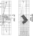
- FIG. 4 shows an example of a path planning solution according to the prior art.
- the objective is the same as that shown and described in conjunction with FIGS. 3A-3C .
- the path planning is performed using an approach based on the A* method.
- A* method path planning each cell along a route is examined and assigned a cost based on the distance from the target location. All examined, but available cells are shown in varying shades of gray in FIG. 4 to represent the corresponding varying costs for the cells. If an obstacle is detected, the corresponding cells are effectively assigned an infinite cost.
- a route is constructed based on the costs associated with the cells and the required direction of travel. As illustrated in FIG. 4 , the examined cells cover a significantly wider area than all of the examined cells shown in FIG. 3C .
- the process described herein places significantly less computational demands on the computer system 20, both in the reduction of total map cells that require examination, and in the processing that is performed to determine the route.
- prior art approaches expend significant computational effort to determine the "best route" from the set of surveyed cells, while the process described herein computes line segments. While the process described herein may not identify a route having the absolute shortest distance/cost, the identified route is sufficiently effective and fast for most applications. Additionally, the identified route requires drastically less computational load, making it more practical in numerous applications, such as for use in unmanned vehicles 12 having relatively small size and power.
- the vehicle 12 is an unmanned vehicle operating in a rail yard.
- the vehicle 12 can comprise a wheeled and/or tracked navigation system that allows it to freely move within the rail yard.
- numerous fixed obstacles are present, which can be avoided by defining a global array of waypoints throughout the rail yard.
- the vehicle 12 can use the predefined waypoints to navigate within the rail yard while using the process described herein to avoid transient obstacles (e.g., cargo containers, parked rail cars, and/or the like), which also are typically present within the rail yard.
- transient obstacles e.g., cargo containers, parked rail cars, and/or the like
- the invention provides a computer program fixed in at least one computer-readable medium, which when executed, enables a computer system to navigate a vehicle.
- the computer-readable medium includes program code, such as the navigation program 30 ( FIG. 1 ), which enables a computer system to implement some or all of a process described herein.
- the term "computer-readable medium" comprises one or more of any type of tangible medium of expression, now known or later developed, from which a copy of the program code can be perceived, reproduced, or otherwise communicated by a computing device.
- the computer-readable medium can comprise: one or more portable storage articles of manufacture; one or more memory/storage components of a computing device; paper; and/or the like.
- the invention provides a method of providing a copy of program code, such as the navigation program 30 ( FIG. 1 ), which enables a computer system to implement some or all of a process described herein.
- a computer system can process a copy of the program code to generate and transmit, for reception at a second, distinct location, a set of data signals that has one or more of its characteristics set and/or changed in such a manner as to encode a copy of the program code in the set of data signals.
- an embodiment of the invention provides a method of acquiring a copy of the program code, which includes a computer system receiving the set of data signals described herein, and translating the set of data signals into a copy of the computer program fixed in at least one computer-readable medium. In either case, the set of data signals can be transmitted/received using any type of communications link.
- the invention provides a method of generating a system for navigating a vehicle.
- the generating can include configuring a computer system, such as the computer system 20 ( FIG. 1 ), to implement the method of navigating a vehicle.
- the configuring can include obtaining (e.g., creating, maintaining, purchasing, modifying, using, making available, etc.) one or more hardware components, with or without one or more software modules, and setting up the components and/or modules to implement a process described herein.
- the configuring can include deploying one or more components to the computer system, which can comprise one or more of: (1) installing program code on a computing device; (2) adding one or more computing and/or I/O devices to the computer system; (3) incorporating and/or modifying the computer system to enable it to perform a process described herein; and/or the like.
Description
- The disclosure relates generally to path planning, and more particularly, to a solution for efficiently planning a path to a destination that avoids obstacles.
- To date, current systems use various path-planning approaches, often derived from network theory. These approaches search large portions of an entire path space during processing for obstacle avoidance. In essence, the processing required for these approaches (e.g., Dijkstra's method, A* path planning, and/or the like) increases according to a total area of the "cost map," or region of interest. In particular, the processing increases in proportion to the square of the increase of the linear dimensions of the region of interest. As a result, the processing required to implement these approaches quickly exceeds the ability of various applications, such as small, portable systems, to readily accommodate, especially while performing other tasks of interest to an operator of portable system (e.g., an unmanned vehicle).
- The increase in processing is partially due to the assumption that way finding and path planning are proactive processes, which must be exhaustively performed by the onboard system of the portable system. Many such approaches calculate cost values for each "cell" in this cost map which are dependent on evaluating the distance, or cost, to the portable system to reach each one, often without considering more obvious heuristics as "am I now backing up rather than moving forward." This leads to many approaches which proactively check and determine path costs through cost map cells which would actually cause the vehicle to back up unnecessarily, even though in the end that course is not selected.
US 7079943 describes a method for planning a path to a destination that avoids obstacles, according to the state of the art. - Aspects of the invention provide a solution for navigating a vehicle. The vehicle is navigated from a start location to a target location using a set of linear paths. A current linear path is identified between a current location of the vehicle and the target location. At least a portion of the current linear path is evaluated for a presence of an obstacle. In response to no obstacle being present along the current linear path, the vehicle is instructed to travel along the current linear path to the target location. In response to an obstacle being present, the vehicle is instructed to travel along a different linear path from the current location to an intermediate location, which is selected based on an extent of the obstacle and the current linear path. The process can be repeated until the vehicle arrives at the target location.
- A first aspect of the invention provides a method comprising: a computer system automatically navigating a vehicle from a current location to a target location, wherein the navigating includes: selecting a set of linear paths for the vehicle to travel between the current location and the target location, the selecting including, for each linear path in the set of linear paths: identifying a current linear path between the current location and the target location; evaluating a set of cells along the current linear path for a presence of an obstacle; instructing the vehicle to travel along the current linear path in response to evaluating all cells between the current location and the target location along the current linear path as not including an obstacle; and in response to evaluating a cell in the set of cells as including an obstacle: determining a center of mass corresponding to an extent of the obstacle; identifying a set of potential locations based on the center of mass, a line through the center of mass and perpendicular to the current linear path, and the extent of the obstacle; selecting a potential location in the set of potential locations as the intermediate location based on the extent of the obstacle and the current linear path; and instructing the vehicle to travel along a distinct linear path from the current location to the intermediate location.
- In a further aspect of the invention each cell corresponds to a minimal navigable area selected based on at least one of: a size or a maneuverability of the vehicle.
In another aspect of the invention the selecting further includes, in response to evaluating a cell in the set of cells as including an obstacle, inflating the extent of the obstacle based on a size of the vehicle, wherein the identifying uses the inflated extent of the obstacle. - In a further aspect of the invention the selecting further includes, in response to evaluating a cell in the set of cells as including an obstacle, calculating a cost for each of a plurality of potential locations in the set of potential locations, wherein the intermediate location corresponds to the potential location having a lowest cost.
- In another aspect of the invention the navigating further including obtaining data corresponding to a set of known attributes for the obstacle, wherein the extent of the obstacle is based on the set of known attributes for the obstacle.
- In a further aspect of the invention the computer system receives the target Location from a user, wherein the computer system automatically navigates the vehicle to the target location in response to receiving the target location.
- In another aspect of the invention the computer system automatically identifies the target location based on a task being performed by the vehicle, wherein the computer system automatically navigates the vehicle to the target location in response to identifying the target location.
- A second aspect of the invention provides a system comprising: a computer system to manage movement of a vehicle by performing the method described hereinbefore.
- In a further aspect of the invention the computer system is located on the vehicle.
- Another aspect of the invention comprises a plurality of sensing devices located on the vehicle, wherein the plurality of sensing devices includes at least one imaging device.
- In a further aspect of the invention the plurality of sensing devices includes a global positioning device.
- In another aspect of the invention the vehicle is an unmanned vehicle.
- In a further aspect of the invention the vehicle is a ground vehicle.
- In another aspect of the invention the vehicle is operating in a rail yard, and wherein the target location corresponds to one of a plurality of waypoints throughout the rail yard, each waypoint corresponding to a location within the rail yard.
- A third aspect of the invention provides the computer system including program code stored on at least one computer-readable partially fixed storage medium, which when executed, enables the computer system to manage movement of the vehicle by performing the method as hereinbefore described.
- Other aspects of the invention provide methods, systems, program products, and methods of using and generating each, which include and/or implement some or all of the actions described herein. The illustrative aspects of the invention are designed to solve one or more of the problems herein described and/or one or more other problems not discussed.
- These and other features of the disclosure will be more readily understood from the following detailed description of the various aspects of the invention taken in conjunction with the accompanying drawings that depict various aspects of the invention.
-
FIG. 1 shows an illustrative environment for managing movement of a vehicle according to an embodiment. -
FIG. 2 shows an illustrative process for navigating a vehicle to a target location according to an embodiment. -
FIGS. 3A-3C show a vehicle traveling from a first location to a target location according to an embodiment. -
FIG. 4 shows an example of a path planning solution according to the prior art. - It is noted that the drawings may not be to scale. The drawings are intended to depict only typical aspects of the invention, and therefore should not be considered as limiting the scope of the invention. In the drawings, like numbering represents like elements between the drawings.
- As indicated above, aspects of the invention provide a solution for navigating a vehicle. The vehicle is navigated from a start location to a target location using a set of linear paths. A current linear path is identified between a current location of the vehicle and the target location. At least a portion of the current linear path is evaluated for a presence of an obstacle. In response to no obstacle being present along the current linear path, the vehicle is instructed to travel along the current linear path to the target location. In response to an obstacle being present, the vehicle is instructed to travel along a different linear path from the current location to an intermediate location, which is selected based on an extent of the obstacle and the current linear path. The process can be repeated until the vehicle arrives at the target location. As used herein, unless otherwise noted, the term "set" means one or more (i.e., at least one) and the phrase "any solution" means any now known or later developed solution.
- Turning to the drawings,
FIG. 1 shows anillustrative environment 10 for managing movement of avehicle 12 according to an embodiment. To this extent, theenvironment 10 includes acomputer system 20 that can perform a process described herein in order to manage movement of thevehicle 12. In particular, thecomputer system 20 is shown including anavigation program 30, which makes thecomputer system 20 operable to manage movement of thevehicle 12 by performing a process described herein. While thecomputer system 20 is shown as being physically located on thevehicle 12, it is understood that thecomputer system 20, or portions thereof, can be located physically apart from thevehicle 12. In this case, thevehicle 12 can include one or more computing devices capable of communicating with thecomputer system 20, e.g., using a wireless solution. - The
computer system 20 is shown including a processing component 22 (e.g., one or more processors), a storage component 24 (e.g., a storage hierarchy), an input/output (I/O) component 26 (e.g., one or more I/O interfaces and/or devices), and acommunications pathway 28. In general, theprocessing component 22 executes program code, such as thenavigation program 30, which is at least partially fixed instorage component 24. While executing program code, theprocessing component 22 can process data, which can result in reading and/or writing transformed data from/to thestorage component 24 and/or the I/O component 26 for further processing. Thepathway 28 provides a communications link between each of the components in thecomputer system 20. The I/O component 26 can comprise one or more human I/O devices, which enable ahuman user 14 to interact with thecomputer system 20 and/or one or more communications devices to enable asystem user 14 to communicate with thecomputer system 20 using any type of communications link. To this extent, thenavigation program 30 can manage a set of interfaces (e.g., graphical user interface(s), application program interface, and/or the like) that enable human and/orsystem users 14 to interact with thenavigation program 30. Furthermore, thenavigation program 30 can manage (e.g., store, retrieve, create, manipulate, organize, present, etc.) the data, such asnavigation data 40, using any solution. - In any event, the
computer system 20 can comprise one or more general purpose computing articles of manufacture (e.g., computing devices) capable of executing program code, such as thenavigation program 30, installed thereon. As used herein, it is understood that "program code" means any collection of instructions, in any language, code or notation, that cause a computing device having an information processing capability to perform a particular action either directly or after any combination of the following: (a) conversion to another language, code or notation; (b) reproduction in a different material form; and/or (c) decompression. To this extent, thenavigation program 30 can be embodied as any combination of system software and/or application software. - Furthermore, the
navigation program 30 can be implemented using a set ofmodules 32. In this case, amodule 32 can enable thecomputer system 20 to perform a set of tasks used by thenavigation program 30, and can be separately developed and/or implemented apart from other portions of thenavigation program 30. As used herein, the term "component" means any configuration of hardware, with or without software, which implements the functionality described in conjunction therewith using any solution, while the term "module" means program code that enables acomputer system 20 to implement the actions described in conjunction therewith using any solution. When fixed in astorage component 24 of acomputer system 20 that includes aprocessing component 22, a module is a substantial portion of a component that implements the actions. Regardless, it is understood that two or more components, modules, and/or systems may share some/all of their respective hardware and/or software. Furthermore, it is understood that some of the functionality discussed herein may not be implemented or additional functionality may be included as part of thecomputer system 20. - When the
computer system 20 comprises multiple computing devices, each computing device can have only a portion of thenavigation program 30 fixed thereon (e.g., one or more modules 32). However, it is understood that thecomputer system 20 and thenavigation program 30 are only representative of various possible equivalent computer systems that may perform a process described herein. To this extent, in other embodiments, the functionality provided by thecomputer system 20 and thenavigation program 30 can be at least partially implemented by one or more computing devices that include any combination of general and/or specific purpose hardware with or without program code. In each embodiment, the hardware and program code, if included, can be created using standard engineering and programming techniques, respectively. - Regardless, when the
computer system 20 includes multiple computing devices, the computing devices can communicate over any type of communications link. Furthermore, while performing a process described herein, thecomputer system 20 can communicate with one or more other computer systems using any type of communications link. In either case, the communications link can comprise any combination of various types of optical fiber, wired, and/or wireless links; comprise any combination of one or more types of networks; and/or utilize any combination of various types of transmission techniques and protocols. - As discussed herein, the
navigation program 30 enables thecomputer system 20 to manage movement of thevehicle 12. In an embodiment, thevehicle 12 is an unmanned vehicle, and thecomputer system 20 is configured to navigate thevehicle 12 in a fully automated manner. Alternatively, thevehicle 12 can be configured to be operated by auser 14 and include acomputer system 20 capable of moving thevehicle 12 in a semi or fully automated manner for certain periods of time. Additionally, thevehicle 12 can be configured to be manually navigated by auser 14. Regardless, in each case thecomputer system 20 can be configured to provide information to auser 14 regarding the movement of thevehicle 12. Theuser 14 can be located on thevehicle 12, operating (e.g., teleoperating) thevehicle 12 from a remote location, monitoring thevehicle 12 from a remote location, and/or the like. - The
vehicle 12 can be any size and/or type ofvehicle 12. For example, thevehicle 12 can be a small device, such as a tread-driven unmanned ground vehicle (e.g., iRobot®, Packbot®, Talon® manufactured by QinetiQ, and/or the like). Alternatively, thevehicle 12 can be a larger vehicle, such as an automated truck navigating in a convoy. Still further, thevehicle 12 can be a waterborne vehicle, an aerial vehicle (e.g., such as a Predator combat drone), an amphibious vehicle, a rail vehicle, and/or the like. - Regardless, as part of managing the movement of the
vehicle 12, thecomputer system 20 can receive a target location and plan a path to travel from the current location of thevehicle 12 to the target destination. Thecomputer system 20 can determine the path using data obtained from a set ofsensing devices 34. Eachsensing device 34 can be configured to obtain (e.g., generate, acquire, and/or the like) data regarding one or more aspects of the environment of thevehicle 12. Asensing device 34 can automatically obtain the data in a periodic manner, obtain the data in response to a request, e.g., from thecomputer system 20, and/or the like. Thesensing device 34 can include one or more sensors for generating data based on one or more attributes of thevehicle 12 and/or its surroundings. Additionally, thesensing device 34 can be configured to acquire data from anexternal data source 16. Regardless, eachsensing device 34 can provide the data for processing by thecomputer system 20, which can store the data asnavigation data 40. - In an embodiment, the
vehicle 12 includes a plurality of types ofsensing devices 34, each of which obtains a data corresponding to the environment of thevehicle 12. Illustrative types of data include a location (e.g., relative or absolute) of thevehicle 12, data corresponding to the environment of the vehicle 12 (e.g., data regarding the terrain, image data, data regarding objects present in the environment, and/or the like).Illustrative sensing devices 34 can include a global positioning system (GPS) device, one or more imaging devices, a local environment data source (e.g., an external imaging device, a weather condition source, a terrain attribute data source, and/or the like), and/or the like. However, it is understood that the types ofsensing devices 34 and types of data are only illustrative, and thevehicle 12 can include any combination of various types ofsensing devices 34, which are configured to obtain any combination of various types of data corresponding to the environment of thevehicle 12. - In any event, the
computer system 20 can be configured to identify a path from a current location to a target location using a process described herein. To this extent, thecomputer system 20 can define a cost map grid for the surrounding area in which thevehicle 12 is located, which can be stored asnavigation data 40. The cost map grid can be bounded or unbounded. In an embodiment, a size of each cell of the cost map grid corresponds to a minimal navigable area for the vehicle. In this case, the size of each cell can be selected based on a size and/or maneuverability of thevehicle 12. For example, the cells of the cost map grid can be squares with each side having a length proportional to a width and/or length of thevehicle 12. In an embodiment, each side of a cell has a length between approximately 0.25 and 1.5 times the width of thevehicle 12. Regardless, the size of each cell can be selected based on the size and maneuverability of the vehicle 12 (e.g., a bicycle versus a semi-trailer truck). In this manner, thecomputer system 20 can be configured to examine potential routes for the path on a scale commensurate with the size and maneuverability of thevehicle 12. -
FIG. 2 shows an illustrative process for navigating the vehicle 12 (FIG. 1 ) to a target location, which can be implemented by the computer system 20 (FIG. 1 ), according to an embodiment. Referring toFIGS. 1 and2 , inaction 102, thecomputer system 20 can obtain a target location (e.g., waypoint) using any solution. For example, auser 14 can transmit a request to thecomputer system 20 for thevehicle 12 to move to the target location. Theuser 14 can be an external director, an external vehicle management system, and/or the like. Alternatively, the computer system 20 (e.g., an internal system responsible for larger-scale navigation planning) can determine the target location based on one or more automated or semi-automated tasks being performed by thevehicle 12. Regardless, the target location can be defined using any solution, such as absolute or relative coordinates (e.g., GPS coordinates), a pre-defined location within an operating area, and/or the like. - In response to obtaining the target location, the
computer system 20 can plan a path from the current location to the target location and navigate thevehicle 12 to the target location.FIGS. 3A-3C show avehicle 12 traveling from afirst location 50 to atarget location 52 according to an embodiment. Referring toFIGS. 1-3C , inaction 104, thecomputer system 20 can determine a directlinear path 60 from thecurrent location 50 of thevehicle 12 to thetarget location 52 using any solution. For example, thecomputer system 20 can use a standard geometric solution for the cost map grid coordinate system. - In
action 106, thecomputer system 20 can determine whether thelinear path 60 includes anyobstacles 2 between thevehicle 12 and thetarget location 52. For example, thecomputer system 20 can evaluate each cell of the cost map grid located along thelinear path 60 until either anobstacle 2 is detected in thepath 60 or all cells from thecurrent location 50 to thetarget location 52 have been evaluated. Thecomputer system 20 can perform the evaluation using any solution. For example, thecomputer system 20 can use image data acquired by an imaging device located on thevehicle 12 to evaluate whether any obstacles 2 (particularly movable objects) are present. Furthermore, thecomputer system 20 can use map data for the surrounding environment to evaluate for the presence of anyobstacles 2 along thepath 60. - When the
computer system 20 does not detect anobstacle 2, inaction 108, thecomputer system 20 can instruct thevehicle 12 to travel to thetarget location 52 along thelinear path 60. While traveling, thecomputer system 20 can monitor thepath 60 for any previously unidentified obstacles 2 (e.g., objects moving into thepath 60, a ditch or other unnavigable terrain, and/or the like). In the event thecomputer system 20 detects anew obstacle 2 prior to arriving at thetarget location 52, the process can return toaction 104. In an embodiment, thecomputer system 20 can distinguish fixed obstacles from movable/moving obstacles. For an obstacle that is moving/recently moved, thecomputer system 20 can stop thevehicle 12 for a period of time (e.g., thirty seconds) to provide an opportunity for the object to move out of thepath 60 prior to returning toaction 104 and determining a new path. - When the
computer system 20 detects anobstacle 2 inaction 106, inaction 110, thecomputer system 20 can determine and inflate an extent of theobstacle 2. Thecomputer system 20 can determine the extent of theobstacle 2 using any solution. For example, thevehicle 12 can include asensing device 34, such as a laser line scanner (e.g., such as a device available from SICK, Inc.), an ultrasonic range finding system, stereo imaging device(s), and/or the like, which can provide sufficiently accurate information as to the presence and location of various types ofobstacles 2 along a field of view/scan field. Using this information, thecomputer system 20 can calculate anapparent extent obstacle 2 on either side of thepath 60. Furthermore, thecomputer system 20 can utilize information regarding known obstacles present the surrounding area to obtain an actual extent of anobstacle 2 known to be present. In either case, thecomputer system 20 can inflate theextents obstacle 2 by an amount sufficient to account for the dimensions of thevehicle 12 to obtaininflated extents obstacle 2. For example, assuming thecomputer system 20 navigates a centerline of thevehicle 12 to a location, theextents obstacle 2 can be inflated by at least one half of the width of thevehicle 12. - In
action 112, thecomputer system 20 can determine a center of mass of theinflated extents obstacle 2 using any solution. The center of mass can correspond to an actual center of mass when the extent of theobstacle 2 is known or an apparent center of mass when the extent of theobstacle 2 is based on partial information regarding the obstacle 2 (e.g., only the visible portion as indicated by the darker portion of theobstacle 2 shown inFIG. 3B ). Inaction 114, thecomputer system 20 can construct aperpendicular line 62 to thepath 60, which intersects the calculated center of mass for the inflated extents of theobstacle 2. - In
action 116, thecomputer system 20 can identify a set of potentialintermediate locations perpendicular line 62 using any solution. For example, thecomputer system 20 can evaluate cells along theperpendicular line 62 from either side of thepath 60 until a cell is identified for which there are no obstacles present between thecurrent location 50 and theintermediate locations action 118, thecomputer system 20 can calculate a cost for traveling to each potentialintermediate location computer system 20 can calculate the cost of a potentialintermediate location intermediate location path 60 for the potentialintermediate location intermediate location target location 52, and/or the like. - In
action 120, thecomputer system 20 can select the potentialintermediate location intermediate location 58A as shown inFIG. 3B , calculate alinear path 64 to theintermediate location 58A, instruct thevehicle 12 to travel to the selectedintermediate location 58A along thelinear path 64, and monitor thevehicle 12 as described herein in conjunction withaction 108. When two or more potentialintermediate locations computer system 20 can select one of the potentialintermediate locations computer system 20 can calculate anew path 66 from theintermediate location 58A to thetarget location 52 to complete a path between the startinglocation 50 and thetarget location 52 via theintermediate location 58A. - Regardless, the process can be repeated for one or more
intermediate locations 58A. For example, as shown inFIG. 3C , once thevehicle 12 arrives at theintermediate location 58A, an obstacle along thepath 66 is visible (e.g., an additional portion of the obstacle 2), which requires thecomputer system 20 to identify and select anotherintermediate location 58C through which to travel in order to travel to thetarget location 52. When located at theintermediate location 58A, thecomputer system 20 cannot locate a potential intermediate location on one side of thepath 66 as the extent of theobstacle 2 extends beyond a field of view of the sensing device(s) of thevehicle 12. In this case, the end of the field of view can be used as an extent of theobstacle 2 in order for thecomputer system 20 to calculate a center of mass and the correspondingperpendicular line 68, which thecomputer system 20 can use to identify theintermediate location 58C and thecorresponding path 70. Once at theintermediate location 58C, thecomputer system 20 identifies a clearlinear path 72 to thetarget location 52 and thevehicle 12 can travel thereto along thepath 72 as described herein. - It is understood that the process described herein is only illustrative, and numerous variations and/or enhancements can be implemented by the
computer system 20. For example, to prevent thecomputer system 20 from continually looping (infinite recursion), thecomputer system 20 can initiate the process with a condition that will cause it to stop. The condition can be simple or complex. For example, the condition can instruct thecomputer system 20 to stop the process when all available courses of travel are duplicates of previously attempted routes, if the edges of an obstacle cannot be discerned in either direction, and/or the like. In response to stopping the process prior to arriving at thetarget location 52, thecomputer system 20 can provide an error message to, for example, auser 14. Theuser 14 can manually define a route for thevehicle 12, retrieve thevehicle 12, and/or the like. - In an embodiment, the
computer system 20 assigns a cost to cells on the cost map grid that are evaluated. For example, a cell can be assigned a value of zero when no obstacle is present between thevehicle 12 and the cell and a value of one when an obstacle is detected. Alternatively, thecomputer system 20 can assign a varying cost based on additional data regarding the corresponding cell. For example, using scanning data for an area using an image based or other type of scanning solution implemented on thevehicle 12, thecomputer system 20 can evaluate a difficulty of traversing terrain, which is not itself an obstacle, corresponding to a cell and assign a weight to the cell based on the evaluated difficulty. The scanning data can include a slope of the terrain, a composition/consistency (e.g., mud versus dry earth) of the terrain, vegetation (e.g., overgrowth) and/or clutter present on the terrain, and/or the like. In this case, the computed cost for a possible path can include consideration of the weight(s) assigned to the cells. In another embodiment, a weight is applied to the entire path rather than to individual cells along the path. - In either case, the weighting can enable the
computer system 20 to choose a longer, but potentially easier and safer, route for thevehicle 12 to travel. Furthermore, thecomputer system 20 can use different thresholds for the difficulty. For example, terrain with a weight greater than a certain amount can be treated as a possible obstacle and the computer system can use the process described herein to determine if lower-cost alternative paths are available. If none are found, thecomputer system 20 can navigate thevehicle 12 along the original straight line path. - When the
computer system 20 has additional data regarding an obstacle and not just data available within a line of sight from the vehicle, thecomputer system 20 can utilize the additional data in a process described herein. For example, the full extent of anobstacle 2 can be used during a re-planning action, which can result in a reduced number of instances in which the course of thevehicle 12 requires re-planning. Similarly, the data can include information regarding a previously utilized or attempted route, which thecomputer system 20 can incorporate in selecting a route to be currently utilized. - Furthermore, while aspects of the invention have been shown and described in conjunction with a ground-based
vehicle 12 application, which therefore assumes a generally two-dimensional environment, it is understood that aspects of the invention can be directed to three-dimensional applications (e.g., aerial, outer space, underwater, and/or the like). In this case, the process described herein can evaluate obstacle dimensions along two perpendicular axes (e.g., up-down and left-right relative to the vehicle 12) to an original plotted direction of travel. Two centers of mass and the corresponding perpendicular lines can be determined, one for each axis, and similar actions can be performed for each axis as described herein. Thecomputer system 20 can compare possible intermediate locations and select the closest overall. Alternatively, thecomputer system 20 can construct vectors from adjacent possible intermediate locations. However, when using vectors, additional obstacles may be encountered as thecomputer system 20 does not check until required. In any event, the solution would generally result in paths that are not perfectly optimal, which are located with very low computational cost (e.g., a near-minimum number of cells may be examined) and can be easily followed by thevehicle 12. - Using a process described herein, the
computer system 20 is required to check a relatively small number of cells as compared to the overall area. For example, as shown inFIG. 3C , the cells are identified by the light gray shading, and include the cells: along thepaths obstacle 2; cells along theperpendicular lines intermediate locations intermediate location 58C and the end of the field of view of thevehicle 12; and cells along thepaths vehicle 12. By utilizing a calculate, then check approach, the process described herein is scalable to large environments. - In contrast, other prior art approaches are not scalable since these approaches, in effect, attempt to evaluate a large number of possible pathways and route options which are not necessary. For example,
FIG. 4 shows an example of a path planning solution according to the prior art. In this case, the objective is the same as that shown and described in conjunction withFIGS. 3A-3C . However, the path planning is performed using an approach based on the A* method. With A* method path planning, each cell along a route is examined and assigned a cost based on the distance from the target location. All examined, but available cells are shown in varying shades of gray inFIG. 4 to represent the corresponding varying costs for the cells. If an obstacle is detected, the corresponding cells are effectively assigned an infinite cost. A route is constructed based on the costs associated with the cells and the required direction of travel. As illustrated inFIG. 4 , the examined cells cover a significantly wider area than all of the examined cells shown inFIG. 3C . - The process described herein places significantly less computational demands on the
computer system 20, both in the reduction of total map cells that require examination, and in the processing that is performed to determine the route. In contrast, prior art approaches expend significant computational effort to determine the "best route" from the set of surveyed cells, while the process described herein computes line segments. While the process described herein may not identify a route having the absolute shortest distance/cost, the identified route is sufficiently effective and fast for most applications. Additionally, the identified route requires drastically less computational load, making it more practical in numerous applications, such as for use inunmanned vehicles 12 having relatively small size and power. - In an illustrative application, the
vehicle 12 is an unmanned vehicle operating in a rail yard. Thevehicle 12 can comprise a wheeled and/or tracked navigation system that allows it to freely move within the rail yard. In an environment such as a rail yard, numerous fixed obstacles are present, which can be avoided by defining a global array of waypoints throughout the rail yard. In this case, thevehicle 12 can use the predefined waypoints to navigate within the rail yard while using the process described herein to avoid transient obstacles (e.g., cargo containers, parked rail cars, and/or the like), which also are typically present within the rail yard. - While shown and described herein as a method and system for navigating a vehicle, it is understood that aspects of the invention further provide various alternative embodiments. For example, in one embodiment, the invention provides a computer program fixed in at least one computer-readable medium, which when executed, enables a computer system to navigate a vehicle. To this extent, the computer-readable medium includes program code, such as the navigation program 30 (
FIG. 1 ), which enables a computer system to implement some or all of a process described herein. It is understood that the term "computer-readable medium" comprises one or more of any type of tangible medium of expression, now known or later developed, from which a copy of the program code can be perceived, reproduced, or otherwise communicated by a computing device. For example, the computer-readable medium can comprise: one or more portable storage articles of manufacture; one or more memory/storage components of a computing device; paper; and/or the like. - In another embodiment, the invention provides a method of providing a copy of program code, such as the navigation program 30 (
FIG. 1 ), which enables a computer system to implement some or all of a process described herein. In this case, a computer system can process a copy of the program code to generate and transmit, for reception at a second, distinct location, a set of data signals that has one or more of its characteristics set and/or changed in such a manner as to encode a copy of the program code in the set of data signals. Similarly, an embodiment of the invention provides a method of acquiring a copy of the program code, which includes a computer system receiving the set of data signals described herein, and translating the set of data signals into a copy of the computer program fixed in at least one computer-readable medium. In either case, the set of data signals can be transmitted/received using any type of communications link. - In still another embodiment, the invention provides a method of generating a system for navigating a vehicle. In this case, the generating can include configuring a computer system, such as the computer system 20 (
FIG. 1 ), to implement the method of navigating a vehicle. The configuring can include obtaining (e.g., creating, maintaining, purchasing, modifying, using, making available, etc.) one or more hardware components, with or without one or more software modules, and setting up the components and/or modules to implement a process described herein. To this extent, the configuring can include deploying one or more components to the computer system, which can comprise one or more of: (1) installing program code on a computing device; (2) adding one or more computing and/or I/O devices to the computer system; (3) incorporating and/or modifying the computer system to enable it to perform a process described herein; and/or the like. - The foregoing description of various aspects of the invention has been presented for purposes of illustration and description. It is not intended to be exhaustive or to limit the invention to the precise form disclosed, and obviously, many modifications and variations are possible. Such modifications and variations that may be apparent to an individual in the art are included within the scope of the invention as defined by the accompanying claims.
Claims (15)
- A method comprising; automatically navigating a vehicle (12) from a current location (50) to a target location (52) using a computer system (20), wherein the navigating includes:selecting a set of linear paths for the vehicle to travel between the current location (50) and the target location (52), the selecting including, for each linear path (60) in the set of linear paths:identifying a current linear path (60) between the current location (50) and the target location (52);evaluating a set of cells along the current linear path (60) for a presence of an obstacle (2);instructing the vehicle to travel along the current linear path (64) in response to evaluating all cells between the current location (50) and the target location (52) along the current linear path(60) as not including an obstacle (2); and
in response to evaluating a cell in the set of cells as including an obstacle (2):determining a center of mass corresponding to an extent (54A, 54B) of the obstacle (2);identifying a set of potential locations based on the center of mass, a line through the center of mass and perpendicular (62) to the current linear path (60), and the extent (54A, 54B) of the obstacle (2);selecting a potential location in the set of potential locations as the intermediate location (58A, 58B) based on the extent (54A, 54B) of the obstacle (2) and the current linear path (60); andinstructing the vehicle to travel along a distinct linear path (60) from the current location (50) to the intermediate location (58A, 58B). - The method of claim 1, wherein each cell corresponds to a minimal navigable area selected based on at least one of: a size or a maneuverability of the vehicle (12).
- The method of either of claims 1 or 2, wherein the selecting further includes, in response to
evaluating a cell in the set of cells as including an obstacle (2), inflating the extent (54A and 54B) of the obstacle (2) based on a size of the vehicle (12), wherein the identifying uses the inflated extent (54A and 54B) of the obstacle (2). - The method of any of claims 1 to 3, wherein the selecting further includes, in response to
evaluating a cell in the set of cells as including an obstacle (2), calculating a cost for each of a plurality of potential locations in the set of potential locations, wherein the intermediate location (58A, 58B) corresponds to the potential location having a lowest cost. - The method of any of claims 1 to 4, the navigating further including obtaining data (40)
corresponding to a set of known attributes for the obstacle (2), wherein the extent (54A and 54B) of the obstacle (2) is based on the set of known attributes for the obstacle (2). - The method of any of claims 1 to 5, further comprising the computer system (20) receiving the target Location (52) from a user (14), wherein the computer system (20) automatically navigates the vehicle (12) to the target location (52) in response to receiving the target location (52).
- The method of any of claims 1 to 6, further comprising the computer system (20) automatically identifying the target location (52) based on a task being performed by the vehicle (12), wherein the computer system (20) automatically navigates the vehicle(12) to the target location (52) in response to identifying the target location (52).
- A system comprising:
a computer system (20) to manage movement of a vehicle(12) by performing the method of any of claims 1 to 7. - The system of claim 8, further comprising the vehicle (12), wherein the computer system (20) is located on the vehicle (12).
- The system of either of claims 8 or 9, further comprising a plurality of sensing devices (34) located on the vehicle (12), wherein the plurality of sensing devices (34) includes at least one imaging device.
- The system of claim 10, wherein the plurality of sensing devices (34) includes a global positioning device.
- The system of any of claims 8 to 11, wherein the vehicle (12) is an unmanned vehicle.
- The system of any of claims 8 to 12, wherein the vehicle (12) is a ground vehicle.
- The system of any of claims 8 to 13, wherein the vehicle (12) is operating in a rail yard, and wherein the target location (52) corresponds to one of a plurality of waypoints throughout the rail yard, each waypoint corresponding to a location within the rail yard.
- Program code (30) suitable for the system of any of the claims 8 to 14, said program code being at least partially fixed and stored on at least one computer-readable storage medium, wherein said program code when executed, enables the computer system (20) to manage movement of the vehicle by performing the method of any of claims 1 to 7.
Applications Claiming Priority (2)
| Application Number | Priority Date | Filing Date | Title |
|---|---|---|---|
| US201261741147P | 2012-07-13 | 2012-07-13 | |
| PCT/US2013/050277 WO2014011990A1 (en) | 2012-07-13 | 2013-07-12 | Straight line path planning |
Publications (3)
| Publication Number | Publication Date |
|---|---|
| EP2872856A1 EP2872856A1 (en) | 2015-05-20 |
| EP2872856A4 EP2872856A4 (en) | 2016-07-06 |
| EP2872856B1 true EP2872856B1 (en) | 2019-09-18 |
Family
ID=49914670
Family Applications (1)
| Application Number | Title | Priority Date | Filing Date |
|---|---|---|---|
| EP13817524.5A Active EP2872856B1 (en) | 2012-07-13 | 2013-07-12 | Straight line path planning |
Country Status (3)
| Country | Link |
|---|---|
| US (1) | US9164510B2 (en) |
| EP (1) | EP2872856B1 (en) |
| WO (1) | WO2014011990A1 (en) |
Families Citing this family (18)
| Publication number | Priority date | Publication date | Assignee | Title |
|---|---|---|---|---|
| US9251627B2 (en) * | 2013-03-05 | 2016-02-02 | Sears Brands, L.L.C. | Removable dashboard instrument system |
| DE102014205170A1 (en) * | 2014-03-20 | 2015-11-26 | Bayerische Motoren Werke Aktiengesellschaft | Method and device for determining a trajectory for a vehicle |
| JP6014192B1 (en) | 2015-03-27 | 2016-10-25 | 本田技研工業株式会社 | Control equipment for unmanned work vehicles |
| US9593959B2 (en) * | 2015-03-31 | 2017-03-14 | International Business Machines Corporation | Linear projection-based navigation |
| US10635913B2 (en) * | 2016-10-17 | 2020-04-28 | Mediatek Inc. | Path planning method and related navigation device |
| US10293485B2 (en) * | 2017-03-30 | 2019-05-21 | Brain Corporation | Systems and methods for robotic path planning |
| KR102275310B1 (en) * | 2017-04-20 | 2021-07-12 | 현대자동차주식회사 | Mtehod of detecting obstacle around vehicle |
| US10677599B2 (en) * | 2017-05-22 | 2020-06-09 | At&T Intellectual Property I, L.P. | Systems and methods for providing improved navigation through interactive suggestion of improved solutions along a path of waypoints |
| US10788831B2 (en) * | 2017-10-06 | 2020-09-29 | Wipro Limited | Method and device for identifying center of a path for navigation of autonomous vehicles |
| CN108088455A (en) * | 2017-12-14 | 2018-05-29 | 山东中图软件技术有限公司 | A kind of air navigation aid |
| US11338438B2 (en) * | 2019-01-25 | 2022-05-24 | Bear Robotics, Inc. | Method, system and non-transitory computer-readable recording medium for determining a movement path of a robot |
| CN110471421B (en) * | 2019-08-27 | 2022-03-18 | 广州小鹏汽车科技有限公司 | Path planning method and path planning system for safe driving of vehicle |
| EP3910158A1 (en) * | 2020-05-13 | 2021-11-17 | Sandvik Mining and Construction Oy | Selecting a route |
| FR3110999B1 (en) * | 2020-05-28 | 2022-10-14 | Airbus Helicopters | Method and system for detection and avoidance of obstacles with several detection spaces for aircraft |
| CN112033413B (en) * | 2020-09-07 | 2023-06-16 | 北京信息科技大学 | Path planning method based on improved A-algorithm combined with environment information |
| CN112066976B (en) * | 2020-09-07 | 2023-06-16 | 北京信息科技大学 | Self-adaptive expansion processing method, system, robot and storage medium |
| US20230089833A1 (en) * | 2021-09-23 | 2023-03-23 | Aurora Flight Sciences, A Subsidiary Of The Boeing Company | Safety assurance for path planners |
| CN114200926B (en) * | 2021-11-12 | 2023-04-07 | 河南工业大学 | Local path planning method and system for unmanned vehicle |
Family Cites Families (16)
| Publication number | Priority date | Publication date | Assignee | Title |
|---|---|---|---|---|
| US5006988A (en) * | 1989-04-28 | 1991-04-09 | University Of Michigan | Obstacle-avoiding navigation system |
| US5650703B1 (en) * | 1990-06-28 | 1999-03-02 | Hk Systems Inc | Downward compatible agv system and methods |
| US20100131078A1 (en) * | 1999-10-27 | 2010-05-27 | Brown David W | Event driven motion systems |
| CA2429828C (en) * | 2000-11-28 | 2011-02-08 | Business Arts Inc. | Gravity gradiometry |
| US20030132855A1 (en) * | 2002-01-11 | 2003-07-17 | Swan Richard J. | Data communication and coherence in a distributed item tracking system |
| US7969306B2 (en) * | 2002-01-11 | 2011-06-28 | Sap Aktiengesellschaft | Context-aware and real-time item tracking system architecture and scenarios |
| US7079943B2 (en) * | 2003-10-07 | 2006-07-18 | Deere & Company | Point-to-point path planning |
| KR100561863B1 (en) | 2004-02-19 | 2006-03-16 | 삼성전자주식회사 | Navigation method and navigation apparatus using virtual sensor for mobile robot |
| JP4089674B2 (en) * | 2004-09-29 | 2008-05-28 | 株式会社デンソー | Contact derailment avoidance navigation system |
| US7248968B2 (en) * | 2004-10-29 | 2007-07-24 | Deere & Company | Obstacle detection using stereo vision |
| US7920962B2 (en) * | 2006-06-19 | 2011-04-05 | Kiva Systems, Inc. | System and method for coordinating movement of mobile drive units |
| EP2041516A2 (en) * | 2006-06-22 | 2009-04-01 | Roy Sandberg | Method and apparatus for robotic path planning, selection, and visualization |
| US8843244B2 (en) * | 2006-10-06 | 2014-09-23 | Irobot Corporation | Autonomous behaviors for a remove vehicle |
| US7818120B2 (en) * | 2006-11-30 | 2010-10-19 | Raytheon Company | Route-planning interactive navigation system and method |
| US20090088912A1 (en) * | 2007-09-28 | 2009-04-02 | Anorad Corporation | Linear driven x-z robot |
| US8229618B2 (en) * | 2008-09-11 | 2012-07-24 | Deere & Company | Leader-follower fully autonomous vehicle with operator on side |
-
2013
- 2013-07-12 WO PCT/US2013/050277 patent/WO2014011990A1/en active Application Filing
- 2013-07-12 EP EP13817524.5A patent/EP2872856B1/en active Active
- 2013-07-13 US US13/941,482 patent/US9164510B2/en active Active
Non-Patent Citations (1)
| Title |
|---|
| None * |
Also Published As
| Publication number | Publication date |
|---|---|
| US20140018996A1 (en) | 2014-01-16 |
| EP2872856A4 (en) | 2016-07-06 |
| US9164510B2 (en) | 2015-10-20 |
| EP2872856A1 (en) | 2015-05-20 |
| WO2014011990A1 (en) | 2014-01-16 |
Similar Documents
| Publication | Publication Date | Title |
|---|---|---|
| EP2872856B1 (en) | Straight line path planning | |
| US10705528B2 (en) | Autonomous visual navigation | |
| EP3642683B1 (en) | 3-d image system for vehicle control | |
| Bakker et al. | Autonomous navigation using a robot platform in a sugar beet field | |
| US8392036B2 (en) | Point and go navigation system and method | |
| US20120299702A1 (en) | Hybrid positioning system | |
| US10386840B2 (en) | Cruise control system and method | |
| EP2177965A2 (en) | High integrity coordination for multiple off-road machines | |
| EP2177964A2 (en) | High integrity coordination system for multiple off-road machines | |
| Stentz et al. | Integrated air/ground vehicle system for semi-autonomous off-road navigation | |
| CN101750972A (en) | Garment for use near autonomous machines | |
| US20190257664A1 (en) | System and method for generating a target path for a vehicle | |
| US10319244B2 (en) | Coordinated planning with graph sharing over networks | |
| Singh et al. | Comparative analysis of range sensors for the robust autonomous navigation–a review | |
| Gonzalez et al. | Planning with uncertainty in position using high-resolution maps | |
| Hellström | Autonomous navigation for forest machines | |
| Cho et al. | Autonomous positioning of the unloading auger of a combine harvester by a laser sensor and GNSS | |
| Uhlmann et al. | NASA Mars rover: A testbed for evaluating applications of covariance intersection | |
| Portugal et al. | ROS Integration of an Instrumented Bobcat T190 for the SEMFIRE Project | |
| Khorrami et al. | A hierarchical path planning and obstacle avoidance system for an autonomous underwater vehicle | |
| Eder et al. | Autonomous robot navigation in alpine terrain | |
| CA3139501C (en) | Localized navigation system controller for power machine | |
| Liu et al. | Sensor-based scouting algorithms for automatic sampling tasks in rough and large unstructured agricultural fields | |
| Soitinaho et al. | Guidance, auto-steering systems and control | |
| Rovira Más et al. | Design of Intelligent Systems |
Legal Events
| Date | Code | Title | Description |
|---|---|---|---|
| PUAI | Public reference made under article 153(3) epc to a published international application that has entered the european phase |
Free format text: ORIGINAL CODE: 0009012 |
|
| 17P | Request for examination filed |
Effective date: 20150211 |
|
| AK | Designated contracting states |
Kind code of ref document: A1 Designated state(s): AL AT BE BG CH CY CZ DE DK EE ES FI FR GB GR HR HU IE IS IT LI LT LU LV MC MK MT NL NO PL PT RO RS SE SI SK SM TR |
|
| AX | Request for extension of the european patent |
Extension state: BA ME |
|
| DAX | Request for extension of the european patent (deleted) | ||
| REG | Reference to a national code |
Ref country code: DE Ref legal event code: R079 Ref document number: 602013060749 Country of ref document: DE Free format text: PREVIOUS MAIN CLASS: G01C0021340000 Ipc: G05D0001020000 |
|
| RA4 | Supplementary search report drawn up and despatched (corrected) |
Effective date: 20160603 |
|
| RIC1 | Information provided on ipc code assigned before grant |
Ipc: G05D 1/02 20060101AFI20160530BHEP |
|
| GRAP | Despatch of communication of intention to grant a patent |
Free format text: ORIGINAL CODE: EPIDOSNIGR1 |
|
| STAA | Information on the status of an ep patent application or granted ep patent |
Free format text: STATUS: GRANT OF PATENT IS INTENDED |
|
| INTG | Intention to grant announced |
Effective date: 20181122 |
|
| GRAJ | Information related to disapproval of communication of intention to grant by the applicant or resumption of examination proceedings by the epo deleted |
Free format text: ORIGINAL CODE: EPIDOSDIGR1 |
|
| STAA | Information on the status of an ep patent application or granted ep patent |
Free format text: STATUS: REQUEST FOR EXAMINATION WAS MADE |
|
| GRAS | Grant fee paid |
Free format text: ORIGINAL CODE: EPIDOSNIGR3 |
|
| STAA | Information on the status of an ep patent application or granted ep patent |
Free format text: STATUS: GRANT OF PATENT IS INTENDED |
|
| GRAP | Despatch of communication of intention to grant a patent |
Free format text: ORIGINAL CODE: EPIDOSNIGR1 |
|
| INTC | Intention to grant announced (deleted) | ||
| INTG | Intention to grant announced |
Effective date: 20190417 |
|
| GRAA | (expected) grant |
Free format text: ORIGINAL CODE: 0009210 |
|
| STAA | Information on the status of an ep patent application or granted ep patent |
Free format text: STATUS: THE PATENT HAS BEEN GRANTED |
|
| AK | Designated contracting states |
Kind code of ref document: B1 Designated state(s): AL AT BE BG CH CY CZ DE DK EE ES FI FR GB GR HR HU IE IS IT LI LT LU LV MC MK MT NL NO PL PT RO RS SE SI SK SM TR |
|
| REG | Reference to a national code |
Ref country code: GB Ref legal event code: FG4D |
|
| REG | Reference to a national code |
Ref country code: CH Ref legal event code: EP |
|
| REG | Reference to a national code |
Ref country code: DE Ref legal event code: R096 Ref document number: 602013060749 Country of ref document: DE |
|
| REG | Reference to a national code |
Ref country code: AT Ref legal event code: REF Ref document number: 1182070 Country of ref document: AT Kind code of ref document: T Effective date: 20191015 |
|
| REG | Reference to a national code |
Ref country code: IE Ref legal event code: FG4D |
|
| REG | Reference to a national code |
Ref country code: NL Ref legal event code: MP Effective date: 20190918 |
|
| PG25 | Lapsed in a contracting state [announced via postgrant information from national office to epo] |
Ref country code: LT Free format text: LAPSE BECAUSE OF FAILURE TO SUBMIT A TRANSLATION OF THE DESCRIPTION OR TO PAY THE FEE WITHIN THE PRESCRIBED TIME-LIMIT Effective date: 20190918 Ref country code: FI Free format text: LAPSE BECAUSE OF FAILURE TO SUBMIT A TRANSLATION OF THE DESCRIPTION OR TO PAY THE FEE WITHIN THE PRESCRIBED TIME-LIMIT Effective date: 20190918 Ref country code: BG Free format text: LAPSE BECAUSE OF FAILURE TO SUBMIT A TRANSLATION OF THE DESCRIPTION OR TO PAY THE FEE WITHIN THE PRESCRIBED TIME-LIMIT Effective date: 20191218 Ref country code: NO Free format text: LAPSE BECAUSE OF FAILURE TO SUBMIT A TRANSLATION OF THE DESCRIPTION OR TO PAY THE FEE WITHIN THE PRESCRIBED TIME-LIMIT Effective date: 20191218 Ref country code: SE Free format text: LAPSE BECAUSE OF FAILURE TO SUBMIT A TRANSLATION OF THE DESCRIPTION OR TO PAY THE FEE WITHIN THE PRESCRIBED TIME-LIMIT Effective date: 20190918 Ref country code: HR Free format text: LAPSE BECAUSE OF FAILURE TO SUBMIT A TRANSLATION OF THE DESCRIPTION OR TO PAY THE FEE WITHIN THE PRESCRIBED TIME-LIMIT Effective date: 20190918 |
|
| REG | Reference to a national code |
Ref country code: LT Ref legal event code: MG4D |
|
| PG25 | Lapsed in a contracting state [announced via postgrant information from national office to epo] |
Ref country code: LV Free format text: LAPSE BECAUSE OF FAILURE TO SUBMIT A TRANSLATION OF THE DESCRIPTION OR TO PAY THE FEE WITHIN THE PRESCRIBED TIME-LIMIT Effective date: 20190918 Ref country code: GR Free format text: LAPSE BECAUSE OF FAILURE TO SUBMIT A TRANSLATION OF THE DESCRIPTION OR TO PAY THE FEE WITHIN THE PRESCRIBED TIME-LIMIT Effective date: 20191219 Ref country code: AL Free format text: LAPSE BECAUSE OF FAILURE TO SUBMIT A TRANSLATION OF THE DESCRIPTION OR TO PAY THE FEE WITHIN THE PRESCRIBED TIME-LIMIT Effective date: 20190918 Ref country code: RS Free format text: LAPSE BECAUSE OF FAILURE TO SUBMIT A TRANSLATION OF THE DESCRIPTION OR TO PAY THE FEE WITHIN THE PRESCRIBED TIME-LIMIT Effective date: 20190918 |
|
| REG | Reference to a national code |
Ref country code: AT Ref legal event code: MK05 Ref document number: 1182070 Country of ref document: AT Kind code of ref document: T Effective date: 20190918 |
|
| PG25 | Lapsed in a contracting state [announced via postgrant information from national office to epo] |
Ref country code: AT Free format text: LAPSE BECAUSE OF FAILURE TO SUBMIT A TRANSLATION OF THE DESCRIPTION OR TO PAY THE FEE WITHIN THE PRESCRIBED TIME-LIMIT Effective date: 20190918 Ref country code: NL Free format text: LAPSE BECAUSE OF FAILURE TO SUBMIT A TRANSLATION OF THE DESCRIPTION OR TO PAY THE FEE WITHIN THE PRESCRIBED TIME-LIMIT Effective date: 20190918 Ref country code: PT Free format text: LAPSE BECAUSE OF FAILURE TO SUBMIT A TRANSLATION OF THE DESCRIPTION OR TO PAY THE FEE WITHIN THE PRESCRIBED TIME-LIMIT Effective date: 20200120 Ref country code: PL Free format text: LAPSE BECAUSE OF FAILURE TO SUBMIT A TRANSLATION OF THE DESCRIPTION OR TO PAY THE FEE WITHIN THE PRESCRIBED TIME-LIMIT Effective date: 20190918 Ref country code: EE Free format text: LAPSE BECAUSE OF FAILURE TO SUBMIT A TRANSLATION OF THE DESCRIPTION OR TO PAY THE FEE WITHIN THE PRESCRIBED TIME-LIMIT Effective date: 20190918 Ref country code: IT Free format text: LAPSE BECAUSE OF FAILURE TO SUBMIT A TRANSLATION OF THE DESCRIPTION OR TO PAY THE FEE WITHIN THE PRESCRIBED TIME-LIMIT Effective date: 20190918 Ref country code: ES Free format text: LAPSE BECAUSE OF FAILURE TO SUBMIT A TRANSLATION OF THE DESCRIPTION OR TO PAY THE FEE WITHIN THE PRESCRIBED TIME-LIMIT Effective date: 20190918 Ref country code: RO Free format text: LAPSE BECAUSE OF FAILURE TO SUBMIT A TRANSLATION OF THE DESCRIPTION OR TO PAY THE FEE WITHIN THE PRESCRIBED TIME-LIMIT Effective date: 20190918 |
|
| PG25 | Lapsed in a contracting state [announced via postgrant information from national office to epo] |
Ref country code: SM Free format text: LAPSE BECAUSE OF FAILURE TO SUBMIT A TRANSLATION OF THE DESCRIPTION OR TO PAY THE FEE WITHIN THE PRESCRIBED TIME-LIMIT Effective date: 20190918 Ref country code: CZ Free format text: LAPSE BECAUSE OF FAILURE TO SUBMIT A TRANSLATION OF THE DESCRIPTION OR TO PAY THE FEE WITHIN THE PRESCRIBED TIME-LIMIT Effective date: 20190918 Ref country code: SK Free format text: LAPSE BECAUSE OF FAILURE TO SUBMIT A TRANSLATION OF THE DESCRIPTION OR TO PAY THE FEE WITHIN THE PRESCRIBED TIME-LIMIT Effective date: 20190918 Ref country code: IS Free format text: LAPSE BECAUSE OF FAILURE TO SUBMIT A TRANSLATION OF THE DESCRIPTION OR TO PAY THE FEE WITHIN THE PRESCRIBED TIME-LIMIT Effective date: 20200224 |
|
| REG | Reference to a national code |
Ref country code: DE Ref legal event code: R097 Ref document number: 602013060749 Country of ref document: DE |
|
| PLBE | No opposition filed within time limit |
Free format text: ORIGINAL CODE: 0009261 |
|
| STAA | Information on the status of an ep patent application or granted ep patent |
Free format text: STATUS: NO OPPOSITION FILED WITHIN TIME LIMIT |
|
| PG2D | Information on lapse in contracting state deleted |
Ref country code: IS |
|
| PG25 | Lapsed in a contracting state [announced via postgrant information from national office to epo] |
Ref country code: DK Free format text: LAPSE BECAUSE OF FAILURE TO SUBMIT A TRANSLATION OF THE DESCRIPTION OR TO PAY THE FEE WITHIN THE PRESCRIBED TIME-LIMIT Effective date: 20190918 Ref country code: IS Free format text: LAPSE BECAUSE OF FAILURE TO SUBMIT A TRANSLATION OF THE DESCRIPTION OR TO PAY THE FEE WITHIN THE PRESCRIBED TIME-LIMIT Effective date: 20200119 |
|
| 26N | No opposition filed |
Effective date: 20200619 |
|
| PG25 | Lapsed in a contracting state [announced via postgrant information from national office to epo] |
Ref country code: SI Free format text: LAPSE BECAUSE OF FAILURE TO SUBMIT A TRANSLATION OF THE DESCRIPTION OR TO PAY THE FEE WITHIN THE PRESCRIBED TIME-LIMIT Effective date: 20190918 |
|
| PG25 | Lapsed in a contracting state [announced via postgrant information from national office to epo] |
Ref country code: MC Free format text: LAPSE BECAUSE OF FAILURE TO SUBMIT A TRANSLATION OF THE DESCRIPTION OR TO PAY THE FEE WITHIN THE PRESCRIBED TIME-LIMIT Effective date: 20190918 |
|
| REG | Reference to a national code |
Ref country code: CH Ref legal event code: PL |
|
| REG | Reference to a national code |
Ref country code: BE Ref legal event code: MM Effective date: 20200731 |
|
| PG25 | Lapsed in a contracting state [announced via postgrant information from national office to epo] |
Ref country code: LI Free format text: LAPSE BECAUSE OF NON-PAYMENT OF DUE FEES Effective date: 20200731 Ref country code: CH Free format text: LAPSE BECAUSE OF NON-PAYMENT OF DUE FEES Effective date: 20200731 Ref country code: LU Free format text: LAPSE BECAUSE OF NON-PAYMENT OF DUE FEES Effective date: 20200712 |
|
| PG25 | Lapsed in a contracting state [announced via postgrant information from national office to epo] |
Ref country code: BE Free format text: LAPSE BECAUSE OF NON-PAYMENT OF DUE FEES Effective date: 20200731 |
|
| PG25 | Lapsed in a contracting state [announced via postgrant information from national office to epo] |
Ref country code: IE Free format text: LAPSE BECAUSE OF NON-PAYMENT OF DUE FEES Effective date: 20200712 |
|
| PG25 | Lapsed in a contracting state [announced via postgrant information from national office to epo] |
Ref country code: TR Free format text: LAPSE BECAUSE OF FAILURE TO SUBMIT A TRANSLATION OF THE DESCRIPTION OR TO PAY THE FEE WITHIN THE PRESCRIBED TIME-LIMIT Effective date: 20190918 Ref country code: MT Free format text: LAPSE BECAUSE OF FAILURE TO SUBMIT A TRANSLATION OF THE DESCRIPTION OR TO PAY THE FEE WITHIN THE PRESCRIBED TIME-LIMIT Effective date: 20190918 Ref country code: CY Free format text: LAPSE BECAUSE OF FAILURE TO SUBMIT A TRANSLATION OF THE DESCRIPTION OR TO PAY THE FEE WITHIN THE PRESCRIBED TIME-LIMIT Effective date: 20190918 |
|
| PG25 | Lapsed in a contracting state [announced via postgrant information from national office to epo] |
Ref country code: MK Free format text: LAPSE BECAUSE OF FAILURE TO SUBMIT A TRANSLATION OF THE DESCRIPTION OR TO PAY THE FEE WITHIN THE PRESCRIBED TIME-LIMIT Effective date: 20190918 |
|
| PGFP | Annual fee paid to national office [announced via postgrant information from national office to epo] |
Ref country code: GB Payment date: 20230727 Year of fee payment: 11 |
|
| REG | Reference to a national code |
Ref country code: DE Ref legal event code: R079 Ref document number: 602013060749 Country of ref document: DE Free format text: PREVIOUS MAIN CLASS: G05D0001020000 Ipc: G05D0001430000 |
|
| PGFP | Annual fee paid to national office [announced via postgrant information from national office to epo] |
Ref country code: FR Payment date: 20230725 Year of fee payment: 11 Ref country code: DE Payment date: 20230727 Year of fee payment: 11 |