EP2801031B1 - Fault-tolerant sensing and monitoring communications bus system for agricultural applications - Google Patents
Fault-tolerant sensing and monitoring communications bus system for agricultural applications Download PDFInfo
- Publication number
- EP2801031B1 EP2801031B1 EP13733907.3A EP13733907A EP2801031B1 EP 2801031 B1 EP2801031 B1 EP 2801031B1 EP 13733907 A EP13733907 A EP 13733907A EP 2801031 B1 EP2801031 B1 EP 2801031B1
- Authority
- EP
- European Patent Office
- Prior art keywords
- sensor
- loop
- control module
- fault tolerant
- communication system
- Prior art date
- Legal status (The legal status is an assumption and is not a legal conclusion. Google has not performed a legal analysis and makes no representation as to the accuracy of the status listed.)
- Active
Links
- 238000004891 communication Methods 0.000 title claims description 91
- 238000012544 monitoring process Methods 0.000 title claims description 46
- 239000003337 fertilizer Substances 0.000 claims description 24
- 230000009977 dual effect Effects 0.000 claims description 10
- 230000002093 peripheral effect Effects 0.000 claims description 9
- 239000000575 pesticide Substances 0.000 claims description 8
- 239000004009 herbicide Substances 0.000 claims description 6
- 230000002363 herbicidal effect Effects 0.000 claims description 5
- CMAUJSNXENPPOF-UHFFFAOYSA-N n-(1,3-benzothiazol-2-ylsulfanyl)-n-cyclohexylcyclohexanamine Chemical compound C1CCCCC1N(C1CCCCC1)SC1=NC2=CC=CC=C2S1 CMAUJSNXENPPOF-UHFFFAOYSA-N 0.000 description 13
- 239000000463 material Substances 0.000 description 8
- 230000007704 transition Effects 0.000 description 7
- 238000009826 distribution Methods 0.000 description 5
- 238000010899 nucleation Methods 0.000 description 5
- 230000001186 cumulative effect Effects 0.000 description 4
- 238000000151 deposition Methods 0.000 description 4
- 238000010586 diagram Methods 0.000 description 4
- 238000009434 installation Methods 0.000 description 4
- 238000000034 method Methods 0.000 description 4
- 150000003839 salts Chemical class 0.000 description 4
- 230000035945 sensitivity Effects 0.000 description 4
- 230000008021 deposition Effects 0.000 description 3
- 230000000737 periodic effect Effects 0.000 description 3
- 230000004044 response Effects 0.000 description 3
- 230000008859 change Effects 0.000 description 2
- 230000003247 decreasing effect Effects 0.000 description 2
- 230000006870 function Effects 0.000 description 2
- 230000036541 health Effects 0.000 description 2
- 238000004519 manufacturing process Methods 0.000 description 2
- 238000005259 measurement Methods 0.000 description 2
- 238000012986 modification Methods 0.000 description 2
- 230000004048 modification Effects 0.000 description 2
- 230000008569 process Effects 0.000 description 2
- 239000011435 rock Substances 0.000 description 2
- 239000004576 sand Substances 0.000 description 2
- 230000007480 spreading Effects 0.000 description 2
- 238000003892 spreading Methods 0.000 description 2
- 241000196324 Embryophyta Species 0.000 description 1
- 244000068988 Glycine max Species 0.000 description 1
- 235000010469 Glycine max Nutrition 0.000 description 1
- 240000008042 Zea mays Species 0.000 description 1
- 235000005824 Zea mays ssp. parviglumis Nutrition 0.000 description 1
- 235000002017 Zea mays subsp mays Nutrition 0.000 description 1
- 238000009825 accumulation Methods 0.000 description 1
- 230000009471 action Effects 0.000 description 1
- 230000008901 benefit Effects 0.000 description 1
- 230000005540 biological transmission Effects 0.000 description 1
- 238000004364 calculation method Methods 0.000 description 1
- 235000005822 corn Nutrition 0.000 description 1
- 238000012272 crop production Methods 0.000 description 1
- 230000001419 dependent effect Effects 0.000 description 1
- 238000001514 detection method Methods 0.000 description 1
- 238000011161 development Methods 0.000 description 1
- 230000018109 developmental process Effects 0.000 description 1
- 230000003292 diminished effect Effects 0.000 description 1
- 238000009313 farming Methods 0.000 description 1
- 239000002917 insecticide Substances 0.000 description 1
- 230000003993 interaction Effects 0.000 description 1
- 238000012423 maintenance Methods 0.000 description 1
- 238000013507 mapping Methods 0.000 description 1
- 230000003287 optical effect Effects 0.000 description 1
- 230000003068 static effect Effects 0.000 description 1
- 238000012360 testing method Methods 0.000 description 1
- 238000013024 troubleshooting Methods 0.000 description 1
Images


Classifications
-
- A—HUMAN NECESSITIES
- A01—AGRICULTURE; FORESTRY; ANIMAL HUSBANDRY; HUNTING; TRAPPING; FISHING
- A01B—SOIL WORKING IN AGRICULTURE OR FORESTRY; PARTS, DETAILS, OR ACCESSORIES OF AGRICULTURAL MACHINES OR IMPLEMENTS, IN GENERAL
- A01B79/00—Methods for working soil
- A01B79/005—Precision agriculture
-
- A—HUMAN NECESSITIES
- A01—AGRICULTURE; FORESTRY; ANIMAL HUSBANDRY; HUNTING; TRAPPING; FISHING
- A01C—PLANTING; SOWING; FERTILISING
- A01C21/00—Methods of fertilising, sowing or planting
-
- A—HUMAN NECESSITIES
- A01—AGRICULTURE; FORESTRY; ANIMAL HUSBANDRY; HUNTING; TRAPPING; FISHING
- A01C—PLANTING; SOWING; FERTILISING
- A01C7/00—Sowing
- A01C7/08—Broadcast seeders; Seeders depositing seeds in rows
- A01C7/10—Devices for adjusting the seed-box ; Regulation of machines for depositing quantities at intervals
- A01C7/102—Regulating or controlling the seed rate
- A01C7/105—Seed sensors
-
- G—PHYSICS
- G01—MEASURING; TESTING
- G01F—MEASURING VOLUME, VOLUME FLOW, MASS FLOW OR LIQUID LEVEL; METERING BY VOLUME
- G01F1/00—Measuring the volume flow or mass flow of fluid or fluent solid material wherein the fluid passes through a meter in a continuous flow
- G01F1/76—Devices for measuring mass flow of a fluid or a fluent solid material
-
- G—PHYSICS
- G05—CONTROLLING; REGULATING
- G05B—CONTROL OR REGULATING SYSTEMS IN GENERAL; FUNCTIONAL ELEMENTS OF SUCH SYSTEMS; MONITORING OR TESTING ARRANGEMENTS FOR SUCH SYSTEMS OR ELEMENTS
- G05B23/00—Testing or monitoring of control systems or parts thereof
- G05B23/02—Electric testing or monitoring
- G05B23/0205—Electric testing or monitoring by means of a monitoring system capable of detecting and responding to faults
- G05B23/0208—Electric testing or monitoring by means of a monitoring system capable of detecting and responding to faults characterized by the configuration of the monitoring system
- G05B23/0216—Human interface functionality, e.g. monitoring system providing help to the user in the selection of tests or in its configuration
-
- G—PHYSICS
- G06—COMPUTING; CALCULATING OR COUNTING
- G06F—ELECTRIC DIGITAL DATA PROCESSING
- G06F11/00—Error detection; Error correction; Monitoring
- G06F11/07—Responding to the occurrence of a fault, e.g. fault tolerance
- G06F11/0703—Error or fault processing not based on redundancy, i.e. by taking additional measures to deal with the error or fault not making use of redundancy in operation, in hardware, or in data representation
- G06F11/0706—Error or fault processing not based on redundancy, i.e. by taking additional measures to deal with the error or fault not making use of redundancy in operation, in hardware, or in data representation the processing taking place on a specific hardware platform or in a specific software environment
- G06F11/0736—Error or fault processing not based on redundancy, i.e. by taking additional measures to deal with the error or fault not making use of redundancy in operation, in hardware, or in data representation the processing taking place on a specific hardware platform or in a specific software environment in functional embedded systems, i.e. in a data processing system designed as a combination of hardware and software dedicated to performing a certain function
-
- G—PHYSICS
- G06—COMPUTING; CALCULATING OR COUNTING
- G06F—ELECTRIC DIGITAL DATA PROCESSING
- G06F11/00—Error detection; Error correction; Monitoring
- G06F11/07—Responding to the occurrence of a fault, e.g. fault tolerance
- G06F11/0703—Error or fault processing not based on redundancy, i.e. by taking additional measures to deal with the error or fault not making use of redundancy in operation, in hardware, or in data representation
- G06F11/079—Root cause analysis, i.e. error or fault diagnosis
-
- G—PHYSICS
- G06—COMPUTING; CALCULATING OR COUNTING
- G06F—ELECTRIC DIGITAL DATA PROCESSING
- G06F11/00—Error detection; Error correction; Monitoring
- G06F11/07—Responding to the occurrence of a fault, e.g. fault tolerance
- G06F11/16—Error detection or correction of the data by redundancy in hardware
- G06F11/20—Error detection or correction of the data by redundancy in hardware using active fault-masking, e.g. by switching out faulty elements or by switching in spare elements
- G06F11/2002—Error detection or correction of the data by redundancy in hardware using active fault-masking, e.g. by switching out faulty elements or by switching in spare elements where interconnections or communication control functionality are redundant
- G06F11/2007—Error detection or correction of the data by redundancy in hardware using active fault-masking, e.g. by switching out faulty elements or by switching in spare elements where interconnections or communication control functionality are redundant using redundant communication media
-
- G—PHYSICS
- G06—COMPUTING; CALCULATING OR COUNTING
- G06F—ELECTRIC DIGITAL DATA PROCESSING
- G06F11/00—Error detection; Error correction; Monitoring
- G06F11/07—Responding to the occurrence of a fault, e.g. fault tolerance
- G06F11/16—Error detection or correction of the data by redundancy in hardware
- G06F11/20—Error detection or correction of the data by redundancy in hardware using active fault-masking, e.g. by switching out faulty elements or by switching in spare elements
- G06F11/2015—Redundant power supplies
-
- H—ELECTRICITY
- H04—ELECTRIC COMMUNICATION TECHNIQUE
- H04L—TRANSMISSION OF DIGITAL INFORMATION, e.g. TELEGRAPHIC COMMUNICATION
- H04L12/00—Data switching networks
- H04L12/28—Data switching networks characterised by path configuration, e.g. LAN [Local Area Networks] or WAN [Wide Area Networks]
- H04L12/40—Bus networks
- H04L12/40169—Flexible bus arrangements
- H04L12/40176—Flexible bus arrangements involving redundancy
-
- H—ELECTRICITY
- H04—ELECTRIC COMMUNICATION TECHNIQUE
- H04L—TRANSMISSION OF DIGITAL INFORMATION, e.g. TELEGRAPHIC COMMUNICATION
- H04L12/00—Data switching networks
- H04L12/28—Data switching networks characterised by path configuration, e.g. LAN [Local Area Networks] or WAN [Wide Area Networks]
- H04L12/42—Loop networks
-
- H—ELECTRICITY
- H04—ELECTRIC COMMUNICATION TECHNIQUE
- H04L—TRANSMISSION OF DIGITAL INFORMATION, e.g. TELEGRAPHIC COMMUNICATION
- H04L41/00—Arrangements for maintenance, administration or management of data switching networks, e.g. of packet switching networks
- H04L41/06—Management of faults, events, alarms or notifications
- H04L41/0654—Management of faults, events, alarms or notifications using network fault recovery
- H04L41/0668—Management of faults, events, alarms or notifications using network fault recovery by dynamic selection of recovery network elements, e.g. replacement by the most appropriate element after failure
-
- H—ELECTRICITY
- H04—ELECTRIC COMMUNICATION TECHNIQUE
- H04L—TRANSMISSION OF DIGITAL INFORMATION, e.g. TELEGRAPHIC COMMUNICATION
- H04L41/00—Arrangements for maintenance, administration or management of data switching networks, e.g. of packet switching networks
- H04L41/06—Management of faults, events, alarms or notifications
- H04L41/0686—Additional information in the notification, e.g. enhancement of specific meta-data
-
- H—ELECTRICITY
- H04—ELECTRIC COMMUNICATION TECHNIQUE
- H04L—TRANSMISSION OF DIGITAL INFORMATION, e.g. TELEGRAPHIC COMMUNICATION
- H04L12/00—Data switching networks
- H04L12/28—Data switching networks characterised by path configuration, e.g. LAN [Local Area Networks] or WAN [Wide Area Networks]
- H04L12/40—Bus networks
- H04L2012/40208—Bus networks characterized by the use of a particular bus standard
- H04L2012/40215—Controller Area Network CAN
-
- H—ELECTRICITY
- H04—ELECTRIC COMMUNICATION TECHNIQUE
- H04L—TRANSMISSION OF DIGITAL INFORMATION, e.g. TELEGRAPHIC COMMUNICATION
- H04L12/00—Data switching networks
- H04L12/28—Data switching networks characterised by path configuration, e.g. LAN [Local Area Networks] or WAN [Wide Area Networks]
- H04L12/40—Bus networks
- H04L2012/4026—Bus for use in automation systems
-
- H—ELECTRICITY
- H04—ELECTRIC COMMUNICATION TECHNIQUE
- H04L—TRANSMISSION OF DIGITAL INFORMATION, e.g. TELEGRAPHIC COMMUNICATION
- H04L67/00—Network arrangements or protocols for supporting network services or applications
- H04L67/01—Protocols
- H04L67/12—Protocols specially adapted for proprietary or special-purpose networking environments, e.g. medical networks, sensor networks, networks in vehicles or remote metering networks
Definitions
- a seed event is said to occur and, for each seed event, the sensors typically send a signal to a central monitor which adds a count to the total count and displays the total count and other information.
- the sectional rate control unit is for example used with a planting system including a planting implement coupled to a work vehicle.
- the implement includes a frame having at least one section supporting multiple row units which are configured to apply a product (e.g., seed, fertilizer, insecticide, herbicide) to the rows in a field.
- Each section includes a product delivery apparatus having a target delivery rate controlled by a section application control signal and at least one product channel for delivering an amount of the product to each of the row units.
- the control unit includes an electronic product sensor coupled to each of the sections and the product channel. The product sensor is configured to generate a product rate signal representative of the amount of the product delivered to the row units.
- An electronic display located in the cab is configured to generate an image in response to a display signal.
- the display includes operator-actuatable switches configured to independently control the state of each of the sections and the target delivery rate of each product for each of the sections.
- a processor circuit is configured to monitor the product rate signal from each product sensor, to calculate product rate data for each product sensor, to generate and apply a display signal to the electronic display to generate the image on the display representing the product rate data for each product in each section, and to generate and apply the section application control signal to each product delivery apparatus in response to actuations of the switches on the electronic display.
- the planter includes a plurality of seed sensors, each associated with a corresponding seed dispensing unit and generating a seed signal representative of the depositing of a seed by the associated seed dispensing unit.
- the monitoring apparatus includes memory for cumulatively storing population data.
- the population data includes a cumulative count of seeds dispensed by each dispensing unit, and a cumulative count of seeds dispensed by all the dispensing units.
- a microprocessor simultaneously receives seed signals from selected seed sensors, asynchronously accumulates and updates the cumulative counts associated with the selected seed sensors, and asynchronously stores the updated cumulative counts in the memory.
- the monitoring apparatus is intended to monitor signals from up to 16 seed sensors.
- multiple data collectors are used to monitor and collect population data locally, i.e., proximate the monitored rows and sensors. The collected data is then serially communicated to a monitor unit in the tractor cab to cut down on the necessary cabling.
- an agricultural communication system that enables sensor-to-sensor link communications of peripheral farming devices (planters, fertilizer or pesticide applicators, etc..) so as to enhance diagnostics for locating system faults.
- the system also provides a means to operate with single-faults present with real-time diagnostics to the operator.
- the point-to-point communications also facilitates simplified installation by automatically determining the sensor addressing based on the physical connection of the sensors. Since the sensor-to-sensor daisy chain bus system is self-configuring there is no dependency on the sensor manufacturing data or sequential installation procedure to define the sensor address as required in other prior art systems.
- the dual power supply from each end of the looped bus with independent switching provides operation in the presence of single-faults, and a diagnostic mode combined with sensor power supply voltage measurements provides fault location.
- the various embodiments of a new communications bus system described herein actually reduces the number of wires and connections of the sensors needed in an overall monitoring system.
- a fault tolerant monitoring and communication system includes at least one peripheral electronic control unit (ECU) adapted to control a dispensed product output from a product dispensing unit and at least one master control module adapted to be communicate with the at least one peripheral electronic control unit.
- ECU peripheral electronic control unit
- master control module adapted to be communicate with the at least one peripheral electronic control unit.
- the monitoring system also includes a control area network (CAN) communications bus configured to interconnect the at least one peripheral ECU with the at least one master module; and a first plurality of sensor units configured and operatively connected in a daisy chain configuration and then operatively coupled to said at least one master module, each of said sensor units being connected in parallel with each other and to a ground line and to a power source on either end of said daisy chain configuration in the monitoring system, each of said sensor units configured to have dual communication with each other.
- the master control module is adapted to communicate with a second plurality of sensor units as well as with an ISO11783 compliant virtual terminal device.
- the dispensed product unit is selected from the group consisting of a seed planter, a fertilizer unit, an herbicide unit and a pesticide unit.
- the master control unit is configured to receive a blockage signal from at least one sensor unit operatively coupled to a dispensing product unit.
- the fault tolerant communication system described above further includes a slave control module operatively coupled to the CAN bus and configured to communicate with a third plurality of sensor units.
- the monitoring system further includes a plurality of slave control modules coupled to the CAN bus having operatively coupled thereto a corresponding at least one plurality of sensor units coupled in a daisy chain configuration.
- a master control module is configured to communicate directly with an ISO 11783 compliant virtual terminal (as a user interface) without a seeder or fertilizer electronic control unit (ECU) with a single CAN bus connecting all of the blockage system modules and the virtual terminal together.
- ECU fertilizer electronic control unit
- This configuration also maximizes the total number of individual sensors which can be monitored.
- an air cart with a ground driven seed meter controls the row dispensing unit and there are then only ECUs associated with the blockage monitoring system.
- the master control module (and associated sensor loop or loops) is configured to communicate directly with virtual terminal to provide for a basic blockage monitoring system.
- the monitoring system is used in salt (or salt) spreading or other material deposition that can get blocked or clogged in a deposition system.
- System 100 includes an array of sensors 110, coupled to a power bus 122, a ground line 124 and a communications bus or lines 126 and 128 and a program in and out line 130 for creating the daisy chain communication between sensors 110.
- power bus 122 is a 12V (volt) line while sensors 110 is comprised of sensors 110-1, 110-2, 110-3 through sensor 110-N.
- One of the challenges with system 100 is that it does not wrap the end of a communications bus 126 and power bus 122 around back to the originating module.
- Typical communications and power bus structures use linear bus architectures terminating after the last node. This creates a bus where a single-fault wiring failure results in reduced functionality or complete communications failure.
- a system 200 is made up of a single or multiple modules, with 1 or 2 sensor loops per module, capable of assigning each loop to one of 2 different blockage groups (seeding or fertilizer in this configuration). This allows the system to independently perform blockage calculations on two different types of applications at the same time.
- an operate mode interaction of a seeding control unit (S-ECU) and the monitoring system includes the steps of:
- the monitoring system described herein also provides enhanced diagnostic messages to aid in troubleshooting. If at any point the system status changes, the monitoring system will generate an alarm message that indicates the type of problem in the system. In this example embodiment, the S-ECU will then request a status of the system to determine the exact problem. There can only be one active alarm in the monitoring system at a given time, hence upon reception of an alarm the S-ECU will acknowledge the alarm and store/display the alarm to the operator. Once an alarm is acknowledged in the monitoring system, the next highest alarm will be posted if any exists.
- a list of alarms is provided in the system hardware and is associated with an Alarm Manager message or signal. This message is sent anytime that an alarm generating unit has detected an alarm condition. Transmission of this message may be periodic or on change of an Alarm Action.
- the alarm bitfield is a bitfielded 16bit value that can represent anything to distinguish an alarm that can be generated from multiple sources. A non-zero bitfield will represent an occurrence of the alarm is present (Alarm On), and a 0 value represents no active occurrences of his alarm exist at this time (Alarm Off). Information about the alarm if applicable (optional) will be provided in the Alarm Data.
- the Alarm Data and Alarm Bitfield are application and alarm number specific.
- This message is sent from the monitoring system (DCBS) to the S-ECU every one second if there is an Alarm engaged that has not been acknowledged by the S-ECU.
- the S-ECU acknowledges the alarm by sending an Alarm Manager Signal Response for that alarm ID.
- the intent of this message is to provide the S-ECU information of DCBS Alarm status.
- One CAN Message is defined for every Alarm ID. After an Alarm is disengaged the Alarm Message will be sent once to indicate that the alarm has cleared.
- the sensor and communication architecture of the various embodiments of the invention allows for full system operation during a single-fault wiring failure.
- a communications interface system 200 disposed between a seeder electronic control unit 202 (S-ECU) and a dispensed product blockage system, a portion of which is shown in FIG. 3 in sensor and communications power loop 300.
- the dispensed product in this example embodiment is a seed, such as corn or soybean.
- the dispensed product is selected from the group consisting of fertilizer, pesticide, herbicide and any other agricultural product or salt, sand or rock when used in commercial applications.
- sensor numbering is designated by the order of the sensors in the loop (until complete):
- S-ECU unit 202 is responsible for mapping the Loop X and Sensor N address to the physical position of a sensor on the Seeding and/or Fertilizer channel.
- This example embodiment shows a multi-module system that includes modules 204, 206 and 208 having coupled thereto sensor loops 214, 216, 218 and 220, each loop being comprised of a plurality of sensors (about 40 sensors in this example) operatively connected to each other in a daisy chain configuration.
- system 200 has a total of 160 sensors.
- S-ECU unit 202 has two CAN communication ports and is capable of communicating with a virtual terminal (VT) 230 via an ISO11783 standard.
- VT virtual terminal
- the dispensed product material system in this example embodiment is located on a second non-ISO CAN Bus.
- master module 204 is configured to communicate directly with an ISO 11783 compliant virtual terminal 230 (as a user interface) without S-ECS unit 202 with a single CAN bus connecting all of the blockage system modules and virtual terminal 230 together. This configuration also maximizes the total number of individual sensors which can be monitored.
- an air cart with a ground driven seed meter controls the row dispensing unit and there are then only ECUs associated with the blockage monitoring system.
- master module 204 (and associated sensor loop or loops) is configured to communicate directly with virtual terminal 230 to provide for a basic blockage monitoring system.
- a monitoring and communication system 300 which includes an array of sensors 310 coupled to a power bus 322, a ground line 324 and a communications bus 326.
- power bus 322 is a 12V (volt) line
- sensors array 310 is comprised of sensors 310-1, 310-2, 310-3 through sensor 310-N.
- One of the advantages of system 300 is that it provides for complete end-to-end communications and power bus loop for a fault-tolerant system. Further, full-duplex serial communications in two directions around a communications loop for fault-tolerant data communications is facilitated thereby providing complete system operation when any single fault occurs. In addition, there is a dual power supply source for fault-tolerant power distribution from both sides of the loop. This provides complete system operation when any single power wiring fault occurs.
- sensor loop diagnostics include module hardware adapted for switching the power supply on and off from each end of the loop.
- system 300 provides its location.
- system 300 provides the location of the open points.
- sensor power supply voltage monitoring and sensor LED-current for monitoring static optical blockage levels, as well as a discrete Push-Pull physical layer transceiver are optimized for cost and performance in an agricultural environment.
- Individual sensor-to-sensor link communications and periodic messages are used to continuously determine the communications health of the system.
- On-demand messages are used to determine integrity of the power bus. This is shown in a Loop Status 340 and a Loop Power Test Result 350 messages from system 300.
- system 300 is used in a Seed Blockage Sensing System such that the communication bus is used for communicating blockage data when the Seed Blockage Sensing system detects a blockage of an overall seed distribution system. Blockage data is communicated on the bus and then an alarm sounds (or any other warning signal) to advise the user that a portion of an air seeder system or a portion of a row planter system is blocked.
- 3 phototransistors and 3 photodiodes are used in the system to detect blockages such as when the planting tube becomes clogged or blocked or the seed is blown out into the ground. Blockage data is communicated to user via the bus.
- multiple LEDs are used opposite a single photodiode cell to detect blockages.
- system 300 is used in a Fertilizer Blockage System wherein the bus is applied to a sensor system detecting the blockage of a granular fertilizer distribution system. Blockage data is communicated on the bus, which is eventually communicated to the user in real-time.
- the bus is used in connection with a counting system which is monitoring seed dispensing row units. Seed counting and timing data is communicated on the bus which is delivered to the user in real-time so that adjustments can be made on a timely basis.
- the sensing element is an infrared LED with an associated light sensor to sense disruptions in the light beam. Seed count data and ground speed data are also used to make real-time adjustments in a planting system (or a fertilizer or pesticide system).
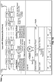
- FIGs. 4A and 4B there is shown a diagram of a state machine 400 of monitoring system (DCBS) 200 and a diagram 450 illustrating a plurality of alive messages in the different states and the transition between states of monitoring system 200.
- DCBS monitoring system
- all control modules coupled to sensor rings
- monitoring system 200 will enter a Ready state 406 or a Failed state 404 and system 200 master module (such as master module 204) will indicate this System State. If the Module Position sequence fails the state will change to Failed.
- Alive messages from master module 204 will indicate the current System State; with this being the only module which the S-ECU will communicate with in this example embodiment. If one or more modules are in Failed state 404, the entire system 200 is in a failed state and a diagnostics screen is optionally presented indicating which of the modules are in the Failed state. Command messages are defined to get the detailed status of any of the modules within the DCBS system.
- the DCBS system is designed to be able to self-initialize without any communication with the S-ECU. The last set configuration is stored in the DCBS and upon power up will configure and check against that configuration. The S-ECU is responsible for making sure the configuration is set correctly.
- the S-ECU may query the DCBS for its configuration to determine if changes are needed, or it can send the configuration on each power up.
- the DCBS will determine if the setting is different than previous and re-initialize if necessary. This will transition the state back to NotReady 402 state until initialization has completed.
- the DCBS In the NotReady state, the DCBS will perform all initializations and start up procedures based on its stored configuration. At completion the DCBS will transition into the Ready or Failed state. During initialization, if the hardware configuration does not match the stored configuration, alarms will be generated.
- ReadyState 406 the DCBS System is waiting for the System start message, which represents the inactive state of the system. Typically a lift switch is used to transition in and out of this state when the machine transitions from in and out of work.
- a RunState 408 the machine indicates that it is in the work state and will begin its blockage monitoring function and report back any blocked rows (which correspond to any blocked dispensing product units).
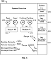
- Display 500 includes images of a Seed module 504, having a set of sensor loops 506 and 508 coupled thereto, and a Fertilizer module 510, having a set of sensor loops 512 and 514 coupled thereto.
- modules are configurable to monitor other materials that can be deposited and can clog or block the dispensing units such as pesticides, herbicides, salt, rock, and sand and the like.
- Display also includes softkeys 520 and 522 for increasing and decreasing seed blockage sensitivity, respectively, as well as softkeys 530 and 532 for increasing and decreasing fertilizer blockage sensitivity, respectively. The results are displayed as Seed Sensitivity 520A and Fertilizer Sensitivity 530A as well as blockage detection for each as 540 along with respective values for each measurement.
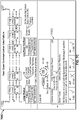
- FIGs. 6A-6C there is illustrated an example embodiment of a dual communication failure between two sets of sensors in two directions (600A-600C) and various associated user displays (650A-650C) of same according to the invention.
- a communication line open from B to A (marked by X) between sensor 42 and 43 and a communication line open from A to B (marked by X) between sensor 44 and 45.
- the sensor count has been set too low, the only one sensor fault/open is detected of 600A in display 650A.
- the sensor count is increased to 4 as in 650B then the correct number of faults are detected.
- 650C indicates the correct number of faults detected as well as all of the sensors in the circuit that are affected by the faults/opens.
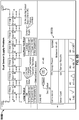
- FIGs. 7A-7D is an example of a loop with 20 sensors (700A-700D) in various states of dual communication failure between sensors and in one or two directions and various associated user displays (750A-750D) of same.
- the sensor count has been set too low, and only 10 sensors are expected but 20 sensors are found and such is indicated in display 750A as an error message and a fail state.
- Loop #2 has 20 sensors (Seed in this example as the Fertilizer feature is turned off) there is a communication line open from A to B (marked by X) between sensor 2 and 3 and a communication line open from B to A (marked by X) between sensor 19 and 20.
- Loop #2 has 20 sensors (Seed in this example as the Fertilizer feature is turned off) with the correct count being reflected in a display 750D so as to be able to detect the correct number of sensors in the loop.
- circuit 700D there is a communication line open from A to B (marked by X) between sensor 18 and 19. It appears from display 750D all of the sensor are detected and that a fault/open is detected and the correct location is also detected. All of the sensors (seed or fertilizer or whatever material is dispensed) will be used in the blockage algorithm and all of the sensors in the loop will report blocked status (see display 750D, Loop #2 is marked with a " ⁇ "), with the blockage occurring between sensors 58 and 59.
- FIG. 8A shows 6 sensors in circuit 800A (sensors 41-46) with the Seed sensor count set to 6 in Loop #2.
- a power line open (marked by X) is shown between sensors 44 and 45 and another power line open (marked by X) between sensors 45 and 46. All of the sensors (seed or fertilizer or whatever material is dispensed) will be ignored by the blockage algorithm and all of the sensors in the loop will be marked as blocked (see display 850A, Loop #2 is marked with an "X") while the Communication display will show an error and the Loop Power will show where the power line open is to be found.
- sensors are shown in circuit 800B (sensors 41-46) with the Seed sensor count set to 6 in Loop #2 (and the Fertilizer feature turned off) with a power line open (marked by X) being shown between sensors 44 and 45. All of the sensors (seed or fertilizer or whatever material is dispensed) are properly detected and counted (Sensor Count - OK); all of the sensors communicating properly (Communication - OK) and no Sensor Results are displayed.
- the Loop Power display however detects the power open line between sensors 44 and 45 in display 850B (see display 850B, Loop #2 is marked with a " ⁇ " between sensors 41-46).
- the various embodiments described above include one or more aspects of the following: complete system operation is maintained when any single fault occurs; sensor loop diagnostics provide information that can be presented to the user to aid in fault location; individual sensor diagnostics provides information that can be presented to the user to aid in pending wiring and connector problems and in determining sensor optics blockage level, which is representative of dirt accumulation or damaged optics.
- a microwave sensor is used instead of an optic sensor to sense the product being dispensed (seed, fertilizer, pesticide and the like).
- the cost of the UART transceiver is reduced from commercially available IC parts (CAN, RS-485, etc.) as the threshold voltage levels have more hysteresis than commercially available IC parts.
- the individual sensor-to-sensor communications link provides a fault-tolerant communications bus while prior art architectures would typically result in stopping all communications on the bus.
- the system user is presented with information from periodic messages to continuously monitor the communications health of the system.
- the user invokes on-demand diagnostics to determine integrity of the power bus.
- the various embodiments of the invention provide diagnostic and configuration messages not found in prior art systems.
- the virtual terminal device is a wireless device coupled to the CAN bus 9 or coupled directly to the master control module.
- the virtual terminal device can also be selected from the group consisting of a tablet, a smartphone, and a notebook PC.
Landscapes
- Engineering & Computer Science (AREA)
- Life Sciences & Earth Sciences (AREA)
- Theoretical Computer Science (AREA)
- Physics & Mathematics (AREA)
- General Physics & Mathematics (AREA)
- Soil Sciences (AREA)
- Computer Networks & Wireless Communication (AREA)
- Signal Processing (AREA)
- Quality & Reliability (AREA)
- General Engineering & Computer Science (AREA)
- Environmental Sciences (AREA)
- Mechanical Engineering (AREA)
- Health & Medical Sciences (AREA)
- Biomedical Technology (AREA)
- Fluid Mechanics (AREA)
- Human Computer Interaction (AREA)
- Automation & Control Theory (AREA)
- Catching Or Destruction (AREA)
- Testing And Monitoring For Control Systems (AREA)
- Fertilizing (AREA)
Description
- The present application claims priority to
U.S. Provisional Application No. 61/584000, filed January 6, 2012 - It is often desirable for an equipment operator to know the rate and quantity of articles being dispensed by certain dispensing equipment. For example, farmers who use mechanized equipment to plant agricultural products must know the quantity of seeds that are being dispensed by the mechanized planting equipment in order to optimize crop production and yield in a given area. Often, a farmer must know the quantity of seeds being planted in each row by the mechanized planter in order to optimize production or even if the seed tube planting device is blocked.
- To provide rate, quantity, timing, total and blockage information to farmers and other operators of equipment, a variety of sensors and systems have been developed which are capable of detecting that an article has passed along or through a predetermined path and displaying article dispensing performance metrics (i.e. rate, quantity, timing, total and blockage). In the case of mechanized seed planting equipment, most of the detecting sensors utilize electro-optical transducers which receive a light beam transmitted across a seed tube which light beam is interrupted or interfered with by the passage of seeds through the tube. Every time the light beam is interrupted or sufficiently diminished below some predetermined threshold, a "seed event" is said to occur and, for each seed event, the sensors typically send a signal to a central monitor which adds a count to the total count and displays the total count and other information.
- In one example agricultural control system disclosed in
U.S. Pat. No. 5,864,781 to White , there is described a multi-drop communications that has single point wiring faults that typically cause this type of bus structure to fail or partially fail. This system appears to use a "unique ID code" for each sensor in the system but this feature results in a burden on configuring the monitoring system. The association of this ID with a sensor position is required during the installation or maintenance of the system and hence is not a quick process since each sensor has to be plugged in sequentially and the installer has to wait on the display to recognize the sensor before plugging in the next one. - Nonetheless, with the increase in complexity of the communications system, there is a need to have enhanced diagnostics, fault-tolerant communication bus, and simplified installation.
- From
US 6 009 354 A there is known a sectional rate control unit for an agricultural implement. The sectional rate control unit is for example used with a planting system including a planting implement coupled to a work vehicle. The implement includes a frame having at least one section supporting multiple row units which are configured to apply a product (e.g., seed, fertilizer, insecticide, herbicide) to the rows in a field. Each section includes a product delivery apparatus having a target delivery rate controlled by a section application control signal and at least one product channel for delivering an amount of the product to each of the row units. The control unit includes an electronic product sensor coupled to each of the sections and the product channel. The product sensor is configured to generate a product rate signal representative of the amount of the product delivered to the row units. An electronic display located in the cab is configured to generate an image in response to a display signal. The display includes operator-actuatable switches configured to independently control the state of each of the sections and the target delivery rate of each product for each of the sections. A processor circuit is configured to monitor the product rate signal from each product sensor, to calculate product rate data for each product sensor, to generate and apply a display signal to the electronic display to generate the image on the display representing the product rate data for each product in each section, and to generate and apply the section application control signal to each product delivery apparatus in response to actuations of the switches on the electronic display. - From
US 5 621 666 A there is known a stand-alone monitoring apparatus for monitoring a plurality of selectable functions of an agricultural planter. The planter includes a plurality of seed sensors, each associated with a corresponding seed dispensing unit and generating a seed signal representative of the depositing of a seed by the associated seed dispensing unit. The monitoring apparatus includes memory for cumulatively storing population data. The population data includes a cumulative count of seeds dispensed by each dispensing unit, and a cumulative count of seeds dispensed by all the dispensing units. A microprocessor simultaneously receives seed signals from selected seed sensors, asynchronously accumulates and updates the cumulative counts associated with the selected seed sensors, and asynchronously stores the updated cumulative counts in the memory. The monitoring apparatus is intended to monitor signals from up to 16 seed sensors. In a related implementation, multiple data collectors are used to monitor and collect population data locally, i.e., proximate the monitored rows and sensors. The collected data is then serially communicated to a monitor unit in the tractor cab to cut down on the necessary cabling. - The object of the invention is attained by a fault-tolerant communication and blockage monitoring system according to
claim 1. Further developments of the invention are specified in the dependent claims. - In one example embodiment, an agricultural communication system is provided that enables sensor-to-sensor link communications of peripheral farming devices (planters, fertilizer or pesticide applicators, etc..) so as to enhance diagnostics for locating system faults. The system also provides a means to operate with single-faults present with real-time diagnostics to the operator. The point-to-point communications also facilitates simplified installation by automatically determining the sensor addressing based on the physical connection of the sensors. Since the sensor-to-sensor daisy chain bus system is self-configuring there is no dependency on the sensor manufacturing data or sequential installation procedure to define the sensor address as required in other prior art systems. The dual power supply from each end of the looped bus with independent switching provides operation in the presence of single-faults, and a diagnostic mode combined with sensor power supply voltage measurements provides fault location. The various embodiments of a new communications bus system described herein actually reduces the number of wires and connections of the sensors needed in an overall monitoring system.
- In a related embodiment, a fault tolerant monitoring and communication system is described herein that includes at least one peripheral electronic control unit (ECU) adapted to control a dispensed product output from a product dispensing unit and at least one master control module adapted to be communicate with the at least one peripheral electronic control unit. The monitoring system also includes a control area network (CAN) communications bus configured to interconnect the at least one peripheral ECU with the at least one master module; and a first plurality of sensor units configured and operatively connected in a daisy chain configuration and then operatively coupled to said at least one master module, each of said sensor units being connected in parallel with each other and to a ground line and to a power source on either end of said daisy chain configuration in the monitoring system, each of said sensor units configured to have dual communication with each other. In a related embodiment, the master control module is adapted to communicate with a second plurality of sensor units as well as with an ISO11783 compliant virtual terminal device.
- In this example embodiment of the monitoring and blockage communication unit, the dispensed product unit is selected from the group consisting of a seed planter, a fertilizer unit, an herbicide unit and a pesticide unit. The master control unit is configured to receive a blockage signal from at least one sensor unit operatively coupled to a dispensing product unit.
- In yet another embodiment, the fault tolerant communication system described above further includes a slave control module operatively coupled to the CAN bus and configured to communicate with a third plurality of sensor units. In a related example embodiment, the monitoring system further includes a plurality of slave control modules coupled to the CAN bus having operatively coupled thereto a corresponding at least one plurality of sensor units coupled in a daisy chain configuration.
- In yet another related embodiment, a master control module is configured to communicate directly with an ISO 11783 compliant virtual terminal (as a user interface) without a seeder or fertilizer electronic control unit (ECU) with a single CAN bus connecting all of the blockage system modules and the virtual terminal together. This configuration also maximizes the total number of individual sensors which can be monitored. In this example embodiment, an air cart with a ground driven seed meter controls the row dispensing unit and there are then only ECUs associated with the blockage monitoring system. In yet another related embodiment, although not shown, the master control module (and associated sensor loop or loops) is configured to communicate directly with virtual terminal to provide for a basic blockage monitoring system.
-
-
FIG. 1 is a schematic of a prior art monitoring system used in an agricultural application. -
FIG. 2 is a schematic of a monitoring and communication system according to the invention. -
FIG. 3 is a schematic of a subsystem of a monitoring and communication system according to the invention. -
FIGs. 4A-4B is a diagram of a state machine of the monitoring system described herein and a diagram illustrating a plurality of alive messages in the different states and the transition between states of the monitoring system. -
FIG. 5 illustrates a user interface display of a monitoring and communication system according to the invention. -
FIGs. 6A-6C is an example of a dual communication failure between two sets of sensors in two directions and various associated user displays of same according to the invention. -
FIGs. 7A-7D is an example of a loop with 20 sensors in various states of dual communication failure between sensors and in one or two directions and various associated user displays of same. -
FIGs. 8A-8B is an example of a dual sensor power problem between two sensors and associated user displays of same. - Following below are more detailed descriptions of various related concepts related to, and embodiments of, improved systems for monitoring and communicating blockages in seeding, fertilizing, herbicide and pesticide spreading applications. In a related embodiment, the monitoring system is used in salt (or salt) spreading or other material deposition that can get blocked or clogged in a deposition system. It should be appreciated that various aspects of the subject matter introduced above and discussed in greater detail below may be implemented in any of numerous ways, as the subject matter is not limited to any particular manner of implementation. Examples of specific implementations and applications are provided primarily for illustrative purposes.
- Referring now to
FIG. 1 , there is shown an example of a previoussensor communication subsystem 100 of a monitoring and communication system, similar to a system described inU.S. Patent No. 5,635,911 issued on June 3, 1997 , entitled "Apparatus and Method for Monitoring an Article Dispensing Device such as a Seed Planter and the like".System 100 includes an array ofsensors 110, coupled to apower bus 122, aground line 124 and a communications bus orlines line 130 for creating the daisy chain communication betweensensors 110. In this example,power bus 122 is a 12V (volt) line whilesensors 110 is comprised of sensors 110-1, 110-2, 110-3 through sensor 110-N. One of the challenges withsystem 100 is that it does not wrap the end of acommunications bus 126 andpower bus 122 around back to the originating module. Typical communications and power bus structures use linear bus architectures terminating after the last node. This creates a bus where a single-fault wiring failure results in reduced functionality or complete communications failure. - In one example embodiment of a novel monitoring and communication system described herein, as shown in
FIG. 2 , asystem 200 is made up of a single or multiple modules, with 1 or 2 sensor loops per module, capable of assigning each loop to one of 2 different blockage groups (seeding or fertilizer in this configuration). This allows the system to independently perform blockage calculations on two different types of applications at the same time. - In this example embodiment, an operate mode interaction of a seeding control unit (S-ECU) and the monitoring system includes the steps of:
- 1. Transmit configuration (at start up)
- 2. Start system
- 3. Receive blockage information from any product deposition unit and Alarms; and
- 4. Stop system
- In a related embodiment, the monitoring system described herein also provides enhanced diagnostic messages to aid in troubleshooting. If at any point the system status changes, the monitoring system will generate an alarm message that indicates the type of problem in the system. In this example embodiment, the S-ECU will then request a status of the system to determine the exact problem. There can only be one active alarm in the monitoring system at a given time, hence upon reception of an alarm the S-ECU will acknowledge the alarm and store/display the alarm to the operator. Once an alarm is acknowledged in the monitoring system, the next highest alarm will be posted if any exists.
- A list of alarms is provided in the system hardware and is associated with an Alarm Manager message or signal. This message is sent anytime that an alarm generating unit has detected an alarm condition. Transmission of this message may be periodic or on change of an Alarm Action. The alarm bitfield is a bitfielded 16bit value that can represent anything to distinguish an alarm that can be generated from multiple sources. A non-zero bitfield will represent an occurrence of the alarm is present (Alarm On), and a 0 value represents no active occurrences of his alarm exist at this time (Alarm Off). Information about the alarm if applicable (optional) will be provided in the Alarm Data. The Alarm Data and Alarm Bitfield are application and alarm number specific. This message is sent from the monitoring system (DCBS) to the S-ECU every one second if there is an Alarm engaged that has not been acknowledged by the S-ECU. The S-ECU acknowledges the alarm by sending an Alarm Manager Signal Response for that alarm ID. The intent of this message is to provide the S-ECU information of DCBS Alarm status. One CAN Message is defined for every Alarm ID. After an Alarm is disengaged the Alarm Message will be sent once to indicate that the alarm has cleared.
- The sensor and communication architecture of the various embodiments of the invention allows for full system operation during a single-fault wiring failure. Referring again to
FIG. 2 , there is shown one example embodiment of acommunications interface system 200 disposed between a seeder electronic control unit 202 (S-ECU) and a dispensed product blockage system, a portion of which is shown inFIG. 3 in sensor andcommunications power loop 300. The dispensed product in this example embodiment is a seed, such as corn or soybean. In a related embodiment, the dispensed product is selected from the group consisting of fertilizer, pesticide, herbicide and any other agricultural product or salt, sand or rock when used in commercial applications. - In this example embodiment, the dispensed product blockage
system incorporating system 200 andsystem 300 is configured to include up to 4 modules and a total of 8 loops (8 x 54 = 432 total sensors). Each module can interface a maximum of 2 sensor loops. In this example embodiment, the maximum number of sensors per loop is 54. In this example embodiment,system 300 is configured to monitor two separate channels: Seeding and Fertilizer. - In this example embodiment, sensor numbering is designated by the order of the sensors in the loop (until complete):
- Loop 1: Sensor 1 - Sensor N (Ex.
Seeder position 1 to 40) - Loop 2: Sensor 1 - Sensor N (Ex.
Seeder position 41 to 80) - Loop 3: Sensor 1 - Sensor N (Ex. Seeder position 81 to 120)
- S-
ECU unit 202 is responsible for mapping the Loop X and Sensor N address to the physical position of a sensor on the Seeding and/or Fertilizer channel. This example embodiment shows a multi-module system that includesmodules sensor loops system 200 has a total of 160 sensors. Inmodule 204, the first module in this example system (Dj# 1, Module Position = 0) will be the dispensed product system master module. In this example embodiment, S-ECU unit 202 has two CAN communication ports and is capable of communicating with a virtual terminal (VT) 230 via an ISO11783 standard. The dispensed product material system in this example embodiment is located on a second non-ISO CAN Bus. - In a related embodiment,
master module 204 is configured to communicate directly with anISO 11783 compliant virtual terminal 230 (as a user interface) without S-ECS unit 202 with a single CAN bus connecting all of the blockage system modules andvirtual terminal 230 together. This configuration also maximizes the total number of individual sensors which can be monitored. In this example embodiment, an air cart with a ground driven seed meter controls the row dispensing unit and there are then only ECUs associated with the blockage monitoring system. In yet another related embodiment, although not shown, master module 204 (and associated sensor loop or loops) is configured to communicate directly withvirtual terminal 230 to provide for a basic blockage monitoring system. - Referring now to
FIG. 3 , there is shown a monitoring andcommunication system 300 according to one example embodiment which includes an array ofsensors 310 coupled to apower bus 322, aground line 324 and acommunications bus 326. In this example embodiment,power bus 322 is a 12V (volt) line, andsensors array 310 is comprised of sensors 310-1, 310-2, 310-3 through sensor 310-N. One of the advantages ofsystem 300 is that it provides for complete end-to-end communications and power bus loop for a fault-tolerant system. Further, full-duplex serial communications in two directions around a communications loop for fault-tolerant data communications is facilitated thereby providing complete system operation when any single fault occurs. In addition, there is a dual power supply source for fault-tolerant power distribution from both sides of the loop. This provides complete system operation when any single power wiring fault occurs. - In various embodiments and variations of
system 300, sensor loop diagnostics include module hardware adapted for switching the power supply on and off from each end of the loop. In the instance, where a single-fault data communications or power distribution fault occurs,system 300 provides its location. Where a double-fault data communications or power distribution fault occurs,system 300 provides the location of the open points. With respect to individual sensor diagnostics, sensor power supply voltage monitoring and sensor LED-current for monitoring static optical blockage levels, as well as a discrete Push-Pull physical layer transceiver are optimized for cost and performance in an agricultural environment. Individual sensor-to-sensor link communications and periodic messages are used to continuously determine the communications health of the system. On-demand messages are used to determine integrity of the power bus. This is shown in aLoop Status 340 and a LoopPower Test Result 350 messages fromsystem 300. - In a related embodiment,
system 300 is used in a Seed Blockage Sensing System such that the communication bus is used for communicating blockage data when the Seed Blockage Sensing system detects a blockage of an overall seed distribution system. Blockage data is communicated on the bus and then an alarm sounds (or any other warning signal) to advise the user that a portion of an air seeder system or a portion of a row planter system is blocked. In this example embodiment, 3 phototransistors and 3 photodiodes are used in the system to detect blockages such as when the planting tube becomes clogged or blocked or the seed is blown out into the ground. Blockage data is communicated to user via the bus. In another example embodiment, multiple LEDs are used opposite a single photodiode cell to detect blockages. - In another related embodiment,
system 300 is used in a Fertilizer Blockage System wherein the bus is applied to a sensor system detecting the blockage of a granular fertilizer distribution system. Blockage data is communicated on the bus, which is eventually communicated to the user in real-time. - In yet another related embodiment, relating to a Seed Counting System, the bus is used in connection with a counting system which is monitoring seed dispensing row units. Seed counting and timing data is communicated on the bus which is delivered to the user in real-time so that adjustments can be made on a timely basis. In this example embodiment, the sensing element is an infrared LED with an associated light sensor to sense disruptions in the light beam. Seed count data and ground speed data are also used to make real-time adjustments in a planting system (or a fertilizer or pesticide system).
- Referring now to
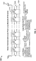
FIGs. 4A and4B , there is shown a diagram of astate machine 400 of monitoring system (DCBS) 200 and a diagram 450 illustrating a plurality of alive messages in the different states and the transition between states ofmonitoring system 200. In this example embodiment, all control modules (coupled to sensor rings) will wake-up in aNotReady state 402 and all initialization and the module position sequence will start. When the module position sequence has successfully completed,monitoring system 200 will enter aReady state 406 or aFailed state 404 andsystem 200 master module (such as master module 204) will indicate this System State. If the Module Position sequence fails the state will change to Failed. Alive messages frommaster module 204 will indicate the current System State; with this being the only module which the S-ECU will communicate with in this example embodiment. If one or more modules are inFailed state 404, theentire system 200 is in a failed state and a diagnostics screen is optionally presented indicating which of the modules are in the Failed state. Command messages are defined to get the detailed status of any of the modules within the DCBS system. The DCBS system is designed to be able to self-initialize without any communication with the S-ECU. The last set configuration is stored in the DCBS and upon power up will configure and check against that configuration. The S-ECU is responsible for making sure the configuration is set correctly. The S-ECU may query the DCBS for its configuration to determine if changes are needed, or it can send the configuration on each power up. When configuration messages are received the DCBS will determine if the setting is different than previous and re-initialize if necessary. This will transition the state back toNotReady 402 state until initialization has completed. - In the NotReady state, the DCBS will perform all initializations and start up procedures based on its stored configuration. At completion the DCBS will transition into the Ready or Failed state. During initialization, if the hardware configuration does not match the stored configuration, alarms will be generated. In
ReadyState 406, the DCBS System is waiting for the System start message, which represents the inactive state of the system. Typically a lift switch is used to transition in and out of this state when the machine transitions from in and out of work. In aRunState 408, the machine indicates that it is in the work state and will begin its blockage monitoring function and report back any blocked rows (which correspond to any blocked dispensing product units). In the FailedState, there is an indication that a failure occurred during the initialization process while the DCBS was in the NotReady state, thereby causing the module to enter a failed state. To transition out of the failed state, the DCBS system failure must be corrected and power cycled or a new module must come online. - Referring now to
FIG. 5 , there is illustrated an example embodiment of auser interface display 500 of a monitoring and communication system according to the invention.Display 500 includes images of aSeed module 504, having a set ofsensor loops Fertilizer module 510, having a set ofsensor loops softkeys softkeys Seed Sensitivity 520A andFertilizer Sensitivity 530A as well as blockage detection for each as 540 along with respective values for each measurement. - Referring now to
FIGs. 6A-6C there is illustrated an example embodiment of a dual communication failure between two sets of sensors in two directions (600A-600C) and various associated user displays (650A-650C) of same according to the invention. In particular, there is a communication line open from B to A (marked by X) betweensensor sensor display 650A. As the sensor count is increased to 4 as in 650B then the correct number of faults are detected. When the sensor count is increased to 6, 650C indicates the correct number of faults detected as well as all of the sensors in the circuit that are affected by the faults/opens. - Referring now to
FIGs. 7A-7D is an example of a loop with 20 sensors (700A-700D) in various states of dual communication failure between sensors and in one or two directions and various associated user displays (750A-750D) of same. In particular, note that in 700A anddisplay 750A, the sensor count has been set too low, and only 10 sensors are expected but 20 sensors are found and such is indicated indisplay 750A as an error message and a fail state. Inexample sensor circuit 700B,Loop # 2 has 20 sensors (Seed in this example as the Fertilizer feature is turned off) there is a communication line open from A to B (marked by X) betweensensor sensor Loop # 2 is marked with an "X"). Inexample sensor circuit 700C, there is a communication line open from A to B (marked by X) betweensensor sensor Loop # 2 is marked with an "X"). - In
example sensor circuit 700D,Loop # 2 has 20 sensors (Seed in this example as the Fertilizer feature is turned off) with the correct count being reflected in adisplay 750D so as to be able to detect the correct number of sensors in the loop. Incircuit 700D, there is a communication line open from A to B (marked by X) betweensensor display 750D all of the sensor are detected and that a fault/open is detected and the correct location is also detected. All of the sensors (seed or fertilizer or whatever material is dispensed) will be used in the blockage algorithm and all of the sensors in the loop will report blocked status (seedisplay 750D,Loop # 2 is marked with a "Δ"), with the blockage occurring between sensors 58 and 59. - Referring now to
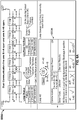
FIGs. 8A-8B , there is shown an example embodiment of a dual sensor power problem and communication failure between two sensors and associated user displays of same. In particular,FIG. 8A shows 6 sensors incircuit 800A (sensors 41-46) with the Seed sensor count set to 6 inLoop # 2. A power line open (marked by X) is shown betweensensors sensors display 850A,Loop # 2 is marked with an "X") while the Communication display will show an error and the Loop Power will show where the power line open is to be found. - Referring now to
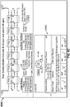
FIG. 8B , in thisembodiment 6 sensors are shown incircuit 800B (sensors 41-46) with the Seed sensor count set to 6 in Loop #2 (and the Fertilizer feature turned off) with a power line open (marked by X) being shown betweensensors sensors display 850B (seedisplay 850B,Loop # 2 is marked with a "Δ" between sensors 41-46). - The various embodiments described above include one or more aspects of the following: complete system operation is maintained when any single fault occurs; sensor loop diagnostics provide information that can be presented to the user to aid in fault location; individual sensor diagnostics provides information that can be presented to the user to aid in pending wiring and connector problems and in determining sensor optics blockage level, which is representative of dirt accumulation or damaged optics. In a related embodiment, a microwave sensor is used instead of an optic sensor to sense the product being dispensed (seed, fertilizer, pesticide and the like). In an example embodiment, the cost of the UART transceiver is reduced from commercially available IC parts (CAN, RS-485, etc.) as the threshold voltage levels have more hysteresis than commercially available IC parts. In the case of a single point wiring short, the individual sensor-to-sensor communications link provides a fault-tolerant communications bus while prior art architectures would typically result in stopping all communications on the bus.
- In this example embodiment, the system user is presented with information from periodic messages to continuously monitor the communications health of the system. The user invokes on-demand diagnostics to determine integrity of the power bus. The various embodiments of the invention provide diagnostic and configuration messages not found in prior art systems.
- In various example embodiments of the blockage monitoring systems described herein, the virtual terminal device is a wireless device coupled to the CAN bus 9 or coupled directly to the master control module. The virtual terminal device can also be selected from the group consisting of a tablet, a smartphone, and a notebook PC.
- While the invention has been described in connection with certain preferred embodiments, there is no intent to limit it to those embodiments. On the contrary, it is recognized that various changes and modifications to the exemplary embodiments described herein will be apparent to those skilled in the art, and that such changes and modifications may be made without departing from the scope of the present invention as defined by the appended claims.
Claims (13)
- A fault tolerant communication and blockage monitoring system for a product dispensing unit, the system comprising:at least one peripheral electronic control unit (202) adapted to monitor product output from the product dispensing unit;at least one master control module (204) adapted to communicate with the at least one peripheral electronic control unit (202), wherein the at least one master control module (204) further includes sensor loop diagnostics;a control area network communications bus configured to interconnect the at least one peripheral electronic control unit (202) with the at least one master control module (204); anda first plurality of sensor units (310),characterized in that the first plurality of sensor units (1-40) is configured and operatively connected in a daisy chain configuration to form a sensor loop (214) that is operatively coupled to said at least one master control module (204), each of said sensor units (1-40) within the loop being connected to a ground line (324) and to a power bus or source (322) on either end of said daisy chain configuration in the monitoring system, each of said sensor units (1-40) further connected at a first end of the sensor loop (214) with a first communication line and connected at a second end of the sensor loop (214) with a second communication line so as to have dual communication in two directions around a communication loop within the sensor loop (214) and individual communication lines between each sensor unit (1-40), wherein power to and communication between each of the sensor units (1-40) is maintained upon occurrence of one of a power loss or a communication line loss on the first or second end of the sensor loop (214), and wherein the sensor loop diagnostics of the at least one master control module (204) provides a location of a wiring fault, power loss or communications loss of a plurality of sensor loops having a fault in the one of the power bus and communications lines in at least one sensor loop (214).
- The fault tolerant communication system of claim 1, wherein the master control module (204) is adapted to communicate with a second plurality of sensor units (41-80).
- The fault tolerant communication system of claim 2, further comprising a slave control module (206) operatively coupled to said control area network communications bus and configured to communicate with a third plurality of sensor units (81-120).
- The fault tolerant communication system of claim 1, wherein the dispensing product unit is selected from the group consisting of a seed planter, a fertilizer spreader, an herbicide spreader and a pesticide unit.
- The fault tolerant communication system of claim 1, wherein said master control module (204) is configured to receive a blockage signal from at least one sensor unit operatively coupled to the dispensing product unit.
- The fault tolerant communication system of claim 3, further comprising a plurality of slave control modules (206, 208) coupled to the control area network communications bus having operatively coupled thereto a corresponding at least one plurality of sensor units (81-120, 121-160) coupled in a daisy chain configuration.
- The fault tolerant communication system of claim 2, further comprising a virtual terminal device (230) operatively coupled to the control area network communications bus and to said peripheral electronic control unit (202) and said master control module (204).
- The fault tolerant communication system of claim 7, wherein the virtual terminal device (230) is a wireless device coupled to the control area network communications bus.
- The fault tolerant communication system of claim 7, wherein the virtual terminal device (230) is selected from the group consisting of a tablet, a smartphone, and a notebook PC.
- The fault tolerant communication system of claim 1, further comprising a slave control module (206) operatively coupled to the control area network communications bus and configured to communicate with a second plurality of sensor units (41-81).
- The fault tolerant communication system of claim 1, further comprising a virtual terminal (230) operatively coupled to the control area network communications bus and to said master control module (204).
- The fault tolerant communication system of claim 7, wherein the control area network communications bus is configured to interconnect the at least one master control module (204) with the virtual terminal (230) and a slave control module (206), said slave module (206) being configured to communicate with a second plurality of sensor units (41-80).
- The fault tolerant communication system of claim 12, wherein at least one peripheral electronic control unit (202) is adapted to control a dispensed product output from a product dispensing unit and is operatively coupled to said control area network communications bus.
Applications Claiming Priority (2)
| Application Number | Priority Date | Filing Date | Title |
|---|---|---|---|
| US201261584000P | 2012-01-06 | 2012-01-06 | |
| PCT/US2013/020464 WO2013103937A1 (en) | 2012-01-06 | 2013-01-07 | Fault-tolerant sensing and monitoring communications bus system for agricultural applications |
Publications (3)
| Publication Number | Publication Date |
|---|---|
| EP2801031A1 EP2801031A1 (en) | 2014-11-12 |
| EP2801031A4 EP2801031A4 (en) | 2015-09-02 |
| EP2801031B1 true EP2801031B1 (en) | 2017-07-19 |
Family
ID=48745469
Family Applications (1)
| Application Number | Title | Priority Date | Filing Date |
|---|---|---|---|
| EP13733907.3A Active EP2801031B1 (en) | 2012-01-06 | 2013-01-07 | Fault-tolerant sensing and monitoring communications bus system for agricultural applications |
Country Status (3)
| Country | Link |
|---|---|
| US (2) | US9307694B2 (en) |
| EP (1) | EP2801031B1 (en) |
| WO (1) | WO2013103937A1 (en) |
Cited By (1)
| Publication number | Priority date | Publication date | Assignee | Title |
|---|---|---|---|---|
| DE102021201877A1 (en) | 2021-02-26 | 2022-09-01 | Matthias Bußjäger | sensor data acquisition system |
Families Citing this family (14)
| Publication number | Priority date | Publication date | Assignee | Title |
|---|---|---|---|---|
| CA2888742C (en) | 2013-09-23 | 2015-09-15 | Jason G. Tatge | Farming data collection and exchange system |
| BR102013027318B1 (en) * | 2013-10-23 | 2019-12-10 | Jose Roberto Do Amaral Assy | process and device for seed failure control in planters |
| US9320192B2 (en) | 2013-11-12 | 2016-04-26 | Dickey-John Corporation | Synchronization of a twin row planting system |
| US9672717B1 (en) * | 2013-12-27 | 2017-06-06 | Alarm.Com Incorporated | Contextual communication of events |
| WO2015143073A1 (en) | 2014-03-19 | 2015-09-24 | Intuitive Surgical Operations, Inc. | Medical devices, systems, and methods integrating eye gaze tracking for stereo viewer |
| DE102015218906B4 (en) * | 2015-09-30 | 2021-06-10 | Siemens Mobility GmbH | Method for operating a data transmission system and data transmission system |
| US10094877B2 (en) * | 2016-02-09 | 2018-10-09 | Nasa Solutions, Llc | Method and apparatus for determining presence and operation of components in a printed circuit board |
| UA127601C2 (en) | 2016-11-01 | 2023-11-01 | Кінз Меньюфекчурінг, Інк. | Control units, nodes, system, and method for transmitting and communicating data |
| CN108234232B (en) * | 2016-12-21 | 2020-10-23 | 杭州海康威视数字技术股份有限公司 | Bus-based fault positioning and loop detection method, device, system and equipment |
| KR102150068B1 (en) * | 2017-12-21 | 2020-08-31 | 주식회사 엘지화학 | Apparatus and method for diagnosing communication fault |
| TWI809285B (en) | 2020-06-30 | 2023-07-21 | 廣達電腦股份有限公司 | Farm sensing system and calibration method of sensor data thereof |
| DE102021205849A1 (en) | 2021-06-10 | 2022-12-15 | Robert Bosch Gesellschaft mit beschränkter Haftung | Method for assigning IDs to participants in a daisy chain arrangement in agricultural applications |
| IT202100032771A1 (en) | 2021-12-28 | 2023-06-28 | Ynnova S R L | IMPROVED OPTICAL DETECTION APPARATUS FOR DETECTION OF SEEDS TRANSITING INTO A SOWING TUBE OF A SEETING MACHINE. |
| IT202100032750A1 (en) | 2021-12-28 | 2023-06-28 | Ynnova S R L | OPTICAL DETECTION APPARATUS FOR THE DETECTION OF SEEDS THAT TRANSIT INTO A SOWING TUBE OF A SEETING MACHINE, IN PARTICULAR OF A ROWED SEEDER. |
Family Cites Families (9)
| Publication number | Priority date | Publication date | Assignee | Title |
|---|---|---|---|---|
| CA2141092C (en) | 1995-01-25 | 1999-01-05 | James F. White | Communication between components of a machine |
| US5621666A (en) * | 1995-04-20 | 1997-04-15 | Dynavisions, Inc. | Planter monitor |
| US5809440A (en) * | 1997-02-27 | 1998-09-15 | Patchen, Inc. | Agricultural implement having multiple agents for mapping fields |
| US6009354A (en) * | 1997-09-23 | 1999-12-28 | Case Corporation | Enhanced implement control |
| US7610122B2 (en) | 2005-08-16 | 2009-10-27 | Deere & Company | Mobile station for an unmanned vehicle |
| US20080262669A1 (en) | 2006-09-22 | 2008-10-23 | Jadi, Inc. | Autonomous vehicle controller |
| EP1950351A3 (en) * | 2007-01-17 | 2010-04-28 | Muncie Power Products, Inc. | Electrohydraulic control system for a vehicle |
| US8319165B2 (en) * | 2007-07-03 | 2012-11-27 | Holland Kyle H | Variable rate chemical management for agricultural landscapes |
| US7861110B2 (en) | 2008-04-30 | 2010-12-28 | Egenera, Inc. | System, method, and adapter for creating fault-tolerant communication busses from standard components |
-
2013
- 2013-01-07 WO PCT/US2013/020464 patent/WO2013103937A1/en active Application Filing
- 2013-01-07 US US14/370,550 patent/US9307694B2/en active Active
- 2013-01-07 EP EP13733907.3A patent/EP2801031B1/en active Active
-
2016
- 2016-04-11 US US15/095,618 patent/US9854726B2/en active Active
Cited By (1)
| Publication number | Priority date | Publication date | Assignee | Title |
|---|---|---|---|---|
| DE102021201877A1 (en) | 2021-02-26 | 2022-09-01 | Matthias Bußjäger | sensor data acquisition system |
Also Published As
| Publication number | Publication date |
|---|---|
| EP2801031A4 (en) | 2015-09-02 |
| US20170006765A1 (en) | 2017-01-12 |
| EP2801031A1 (en) | 2014-11-12 |
| US9854726B2 (en) | 2018-01-02 |
| US9307694B2 (en) | 2016-04-12 |
| US20140343806A1 (en) | 2014-11-20 |
| WO2013103937A1 (en) | 2013-07-11 |
Similar Documents
| Publication | Publication Date | Title |
|---|---|---|
| EP2801031B1 (en) | Fault-tolerant sensing and monitoring communications bus system for agricultural applications | |
| AU2018200214B2 (en) | Systems, methods and apparatus for multi-row agricultural implement control and monitoring | |
| US8781693B2 (en) | Method for automatic location identification of electronic devices on agricultural implements | |
| US20230229142A1 (en) | Methods and systems for using duty cycle of sensors to determine seed or particle flow rate | |
| US6091997A (en) | Enhanced statistical/status display | |
| US9330062B2 (en) | Vehicle control and gateway module | |
| US6009354A (en) | Enhanced implement control | |
| US5621666A (en) | Planter monitor | |
| US5323721A (en) | Planter monitor system | |
| US6661514B1 (en) | Tube blockage monitor | |
| CA2914686C (en) | Wireless flow monitoring system for an air seeder | |
| US9324197B2 (en) | Method and system for managing the hand-off between control terminals | |
| US20160246296A1 (en) | Gateway system and method | |
| EP2966966B1 (en) | Gateway module | |
| EP3061334A1 (en) | Method and device for avoiding seed-metering errors in planters | |
| CN103605307A (en) | Device and method for monitoring corn precision seeding operation | |
| CA2944423C (en) | Method and system for managing the hand-off between control terminals | |
| US20220279705A1 (en) | Method and systems for using sensors to determine relative seed or particle speed | |
| RU2757494C1 (en) | Seed sowing control system | |
| US20240065135A1 (en) | Multiple networks monitor | |
| US20220260747A1 (en) | Systems, methods, and apparatus for the operation of electronic components and the display of information related to agricultural implements |
Legal Events
| Date | Code | Title | Description |
|---|---|---|---|
| PUAI | Public reference made under article 153(3) epc to a published international application that has entered the european phase |
Free format text: ORIGINAL CODE: 0009012 |
|
| 17P | Request for examination filed |
Effective date: 20140718 |
|
| AK | Designated contracting states |
Kind code of ref document: A1 Designated state(s): AL AT BE BG CH CY CZ DE DK EE ES FI FR GB GR HR HU IE IS IT LI LT LU LV MC MK MT NL NO PL PT RO RS SE SI SK SM TR |
|
| DAX | Request for extension of the european patent (deleted) | ||
| RA4 | Supplementary search report drawn up and despatched (corrected) |
Effective date: 20150730 |
|
| RIC1 | Information provided on ipc code assigned before grant |
Ipc: G06F 11/00 20060101AFI20150724BHEP Ipc: A01B 79/00 20060101ALI20150724BHEP Ipc: A01C 17/00 20060101ALI20150724BHEP Ipc: A01C 7/10 20060101ALI20150724BHEP Ipc: G06F 11/20 20060101ALI20150724BHEP |
|
| 17Q | First examination report despatched |
Effective date: 20160727 |
|
| REG | Reference to a national code |
Ref country code: DE Ref legal event code: R079 Ref document number: 602013023738 Country of ref document: DE Free format text: PREVIOUS MAIN CLASS: G06F0011000000 Ipc: G06F0011070000 |
|
| GRAJ | Information related to disapproval of communication of intention to grant by the applicant or resumption of examination proceedings by the epo deleted |
Free format text: ORIGINAL CODE: EPIDOSDIGR1 |
|
| GRAP | Despatch of communication of intention to grant a patent |
Free format text: ORIGINAL CODE: EPIDOSNIGR1 |
|
| GRAC | Information related to communication of intention to grant a patent modified |
Free format text: ORIGINAL CODE: EPIDOSCIGR1 |
|
| RIC1 | Information provided on ipc code assigned before grant |
Ipc: H04L 12/42 20060101ALI20170110BHEP Ipc: G01F 1/76 20060101ALI20170110BHEP Ipc: A01C 21/00 20060101ALI20170110BHEP Ipc: G06F 11/20 20060101ALI20170110BHEP Ipc: H04L 12/40 20060101ALI20170110BHEP Ipc: G06F 11/07 20060101AFI20170110BHEP Ipc: A01B 79/00 20060101ALI20170110BHEP Ipc: A01C 7/10 20060101ALI20170110BHEP |
|
| INTG | Intention to grant announced |
Effective date: 20170124 |
|
| GRAS | Grant fee paid |
Free format text: ORIGINAL CODE: EPIDOSNIGR3 |
|
| GRAA | (expected) grant |
Free format text: ORIGINAL CODE: 0009210 |
|
| AK | Designated contracting states |
Kind code of ref document: B1 Designated state(s): AL AT BE BG CH CY CZ DE DK EE ES FI FR GB GR HR HU IE IS IT LI LT LU LV MC MK MT NL NO PL PT RO RS SE SI SK SM TR |
|
| REG | Reference to a national code |
Ref country code: GB Ref legal event code: FG4D |
|
| REG | Reference to a national code |
Ref country code: CH Ref legal event code: EP |
|
| REG | Reference to a national code |
Ref country code: IE Ref legal event code: FG4D |
|
| REG | Reference to a national code |
Ref country code: AT Ref legal event code: REF Ref document number: 911018 Country of ref document: AT Kind code of ref document: T Effective date: 20170815 |
|
| REG | Reference to a national code |
Ref country code: DE Ref legal event code: R096 Ref document number: 602013023738 Country of ref document: DE |
|
| REG | Reference to a national code |
Ref country code: SE Ref legal event code: TRGR |
|
| REG | Reference to a national code |
Ref country code: NL Ref legal event code: MP Effective date: 20170719 |
|
| REG | Reference to a national code |
Ref country code: LT Ref legal event code: MG4D |
|
| REG | Reference to a national code |
Ref country code: AT Ref legal event code: MK05 Ref document number: 911018 Country of ref document: AT Kind code of ref document: T Effective date: 20170719 |
|
| REG | Reference to a national code |
Ref country code: FR Ref legal event code: PLFP Year of fee payment: 6 |
|
| PG25 | Lapsed in a contracting state [announced via postgrant information from national office to epo] |
Ref country code: LT Free format text: LAPSE BECAUSE OF FAILURE TO SUBMIT A TRANSLATION OF THE DESCRIPTION OR TO PAY THE FEE WITHIN THE PRESCRIBED TIME-LIMIT Effective date: 20170719 Ref country code: NL Free format text: LAPSE BECAUSE OF FAILURE TO SUBMIT A TRANSLATION OF THE DESCRIPTION OR TO PAY THE FEE WITHIN THE PRESCRIBED TIME-LIMIT Effective date: 20170719 Ref country code: HR Free format text: LAPSE BECAUSE OF FAILURE TO SUBMIT A TRANSLATION OF THE DESCRIPTION OR TO PAY THE FEE WITHIN THE PRESCRIBED TIME-LIMIT Effective date: 20170719 Ref country code: FI Free format text: LAPSE BECAUSE OF FAILURE TO SUBMIT A TRANSLATION OF THE DESCRIPTION OR TO PAY THE FEE WITHIN THE PRESCRIBED TIME-LIMIT Effective date: 20170719 Ref country code: NO Free format text: LAPSE BECAUSE OF FAILURE TO SUBMIT A TRANSLATION OF THE DESCRIPTION OR TO PAY THE FEE WITHIN THE PRESCRIBED TIME-LIMIT Effective date: 20171019 Ref country code: AT Free format text: LAPSE BECAUSE OF FAILURE TO SUBMIT A TRANSLATION OF THE DESCRIPTION OR TO PAY THE FEE WITHIN THE PRESCRIBED TIME-LIMIT Effective date: 20170719 |
|
| PG25 | Lapsed in a contracting state [announced via postgrant information from national office to epo] |
Ref country code: BG Free format text: LAPSE BECAUSE OF FAILURE TO SUBMIT A TRANSLATION OF THE DESCRIPTION OR TO PAY THE FEE WITHIN THE PRESCRIBED TIME-LIMIT Effective date: 20171019 Ref country code: IS Free format text: LAPSE BECAUSE OF FAILURE TO SUBMIT A TRANSLATION OF THE DESCRIPTION OR TO PAY THE FEE WITHIN THE PRESCRIBED TIME-LIMIT Effective date: 20171119 Ref country code: PL Free format text: LAPSE BECAUSE OF FAILURE TO SUBMIT A TRANSLATION OF THE DESCRIPTION OR TO PAY THE FEE WITHIN THE PRESCRIBED TIME-LIMIT Effective date: 20170719 Ref country code: ES Free format text: LAPSE BECAUSE OF FAILURE TO SUBMIT A TRANSLATION OF THE DESCRIPTION OR TO PAY THE FEE WITHIN THE PRESCRIBED TIME-LIMIT Effective date: 20170719 Ref country code: GR Free format text: LAPSE BECAUSE OF FAILURE TO SUBMIT A TRANSLATION OF THE DESCRIPTION OR TO PAY THE FEE WITHIN THE PRESCRIBED TIME-LIMIT Effective date: 20171020 Ref country code: LV Free format text: LAPSE BECAUSE OF FAILURE TO SUBMIT A TRANSLATION OF THE DESCRIPTION OR TO PAY THE FEE WITHIN THE PRESCRIBED TIME-LIMIT Effective date: 20170719 Ref country code: RS Free format text: LAPSE BECAUSE OF FAILURE TO SUBMIT A TRANSLATION OF THE DESCRIPTION OR TO PAY THE FEE WITHIN THE PRESCRIBED TIME-LIMIT Effective date: 20170719 |
|
| REG | Reference to a national code |
Ref country code: DE Ref legal event code: R097 Ref document number: 602013023738 Country of ref document: DE |
|
| PG25 | Lapsed in a contracting state [announced via postgrant information from national office to epo] |
Ref country code: CZ Free format text: LAPSE BECAUSE OF FAILURE TO SUBMIT A TRANSLATION OF THE DESCRIPTION OR TO PAY THE FEE WITHIN THE PRESCRIBED TIME-LIMIT Effective date: 20170719 Ref country code: RO Free format text: LAPSE BECAUSE OF FAILURE TO SUBMIT A TRANSLATION OF THE DESCRIPTION OR TO PAY THE FEE WITHIN THE PRESCRIBED TIME-LIMIT Effective date: 20170719 Ref country code: DK Free format text: LAPSE BECAUSE OF FAILURE TO SUBMIT A TRANSLATION OF THE DESCRIPTION OR TO PAY THE FEE WITHIN THE PRESCRIBED TIME-LIMIT Effective date: 20170719 |
|
| PLBE | No opposition filed within time limit |
Free format text: ORIGINAL CODE: 0009261 |
|
| STAA | Information on the status of an ep patent application or granted ep patent |
Free format text: STATUS: NO OPPOSITION FILED WITHIN TIME LIMIT |
|
| PG25 | Lapsed in a contracting state [announced via postgrant information from national office to epo] |
Ref country code: SK Free format text: LAPSE BECAUSE OF FAILURE TO SUBMIT A TRANSLATION OF THE DESCRIPTION OR TO PAY THE FEE WITHIN THE PRESCRIBED TIME-LIMIT Effective date: 20170719 Ref country code: EE Free format text: LAPSE BECAUSE OF FAILURE TO SUBMIT A TRANSLATION OF THE DESCRIPTION OR TO PAY THE FEE WITHIN THE PRESCRIBED TIME-LIMIT Effective date: 20170719 Ref country code: SM Free format text: LAPSE BECAUSE OF FAILURE TO SUBMIT A TRANSLATION OF THE DESCRIPTION OR TO PAY THE FEE WITHIN THE PRESCRIBED TIME-LIMIT Effective date: 20170719 |
|
| 26N | No opposition filed |
Effective date: 20180420 |
|
| PG25 | Lapsed in a contracting state [announced via postgrant information from national office to epo] |
Ref country code: SI Free format text: LAPSE BECAUSE OF FAILURE TO SUBMIT A TRANSLATION OF THE DESCRIPTION OR TO PAY THE FEE WITHIN THE PRESCRIBED TIME-LIMIT Effective date: 20170719 |
|
| REG | Reference to a national code |
Ref country code: CH Ref legal event code: PL |
|
| PG25 | Lapsed in a contracting state [announced via postgrant information from national office to epo] |
Ref country code: LU Free format text: LAPSE BECAUSE OF NON-PAYMENT OF DUE FEES Effective date: 20180107 |
|
| REG | Reference to a national code |
Ref country code: IE Ref legal event code: MM4A |
|
| REG | Reference to a national code |
Ref country code: BE Ref legal event code: MM Effective date: 20180131 |
|
| PG25 | Lapsed in a contracting state [announced via postgrant information from national office to epo] |
Ref country code: LI Free format text: LAPSE BECAUSE OF NON-PAYMENT OF DUE FEES Effective date: 20180131 Ref country code: CH Free format text: LAPSE BECAUSE OF NON-PAYMENT OF DUE FEES Effective date: 20180131 Ref country code: BE Free format text: LAPSE BECAUSE OF NON-PAYMENT OF DUE FEES Effective date: 20180131 |
|
| PG25 | Lapsed in a contracting state [announced via postgrant information from national office to epo] |
Ref country code: IE Free format text: LAPSE BECAUSE OF NON-PAYMENT OF DUE FEES Effective date: 20180107 |
|
| PG25 | Lapsed in a contracting state [announced via postgrant information from national office to epo] |
Ref country code: MC Free format text: LAPSE BECAUSE OF FAILURE TO SUBMIT A TRANSLATION OF THE DESCRIPTION OR TO PAY THE FEE WITHIN THE PRESCRIBED TIME-LIMIT Effective date: 20170719 |
|
| PG25 | Lapsed in a contracting state [announced via postgrant information from national office to epo] |
Ref country code: MT Free format text: LAPSE BECAUSE OF NON-PAYMENT OF DUE FEES Effective date: 20180107 |
|
| PG25 | Lapsed in a contracting state [announced via postgrant information from national office to epo] |
Ref country code: TR Free format text: LAPSE BECAUSE OF FAILURE TO SUBMIT A TRANSLATION OF THE DESCRIPTION OR TO PAY THE FEE WITHIN THE PRESCRIBED TIME-LIMIT Effective date: 20170719 |
|
| PG25 | Lapsed in a contracting state [announced via postgrant information from national office to epo] |
Ref country code: PT Free format text: LAPSE BECAUSE OF FAILURE TO SUBMIT A TRANSLATION OF THE DESCRIPTION OR TO PAY THE FEE WITHIN THE PRESCRIBED TIME-LIMIT Effective date: 20170719 Ref country code: HU Free format text: LAPSE BECAUSE OF FAILURE TO SUBMIT A TRANSLATION OF THE DESCRIPTION OR TO PAY THE FEE WITHIN THE PRESCRIBED TIME-LIMIT; INVALID AB INITIO Effective date: 20130107 |
|
| PG25 | Lapsed in a contracting state [announced via postgrant information from national office to epo] |
Ref country code: CY Free format text: LAPSE BECAUSE OF FAILURE TO SUBMIT A TRANSLATION OF THE DESCRIPTION OR TO PAY THE FEE WITHIN THE PRESCRIBED TIME-LIMIT Effective date: 20170719 Ref country code: MK Free format text: LAPSE BECAUSE OF NON-PAYMENT OF DUE FEES Effective date: 20170719 |
|
| PG25 | Lapsed in a contracting state [announced via postgrant information from national office to epo] |
Ref country code: AL Free format text: LAPSE BECAUSE OF FAILURE TO SUBMIT A TRANSLATION OF THE DESCRIPTION OR TO PAY THE FEE WITHIN THE PRESCRIBED TIME-LIMIT Effective date: 20170719 |
|
| PGFP | Annual fee paid to national office [announced via postgrant information from national office to epo] |
Ref country code: IT Payment date: 20221213 Year of fee payment: 11 |
|
| PGFP | Annual fee paid to national office [announced via postgrant information from national office to epo] |
Ref country code: GB Payment date: 20231116 Year of fee payment: 12 |
|
| PGFP | Annual fee paid to national office [announced via postgrant information from national office to epo] |
Ref country code: SE Payment date: 20231127 Year of fee payment: 12 Ref country code: FR Payment date: 20231122 Year of fee payment: 12 |
|
| PGFP | Annual fee paid to national office [announced via postgrant information from national office to epo] |
Ref country code: DE Payment date: 20231121 Year of fee payment: 12 |