EP2697701B1 - Method and apparatus for efficient scheduling for multiple automated non-holonomic vehicles using a coordinated path planner - Google Patents
Method and apparatus for efficient scheduling for multiple automated non-holonomic vehicles using a coordinated path planner Download PDFInfo
- Publication number
- EP2697701B1 EP2697701B1 EP12770733.9A EP12770733A EP2697701B1 EP 2697701 B1 EP2697701 B1 EP 2697701B1 EP 12770733 A EP12770733 A EP 12770733A EP 2697701 B1 EP2697701 B1 EP 2697701B1
- Authority
- EP
- European Patent Office
- Prior art keywords
- nodes
- path
- automated
- automated vehicles
- vehicles
- Prior art date
- Legal status (The legal status is an assumption and is not a legal conclusion. Google has not performed a legal analysis and makes no representation as to the accuracy of the status listed.)
- Active
Links
- 238000000034 method Methods 0.000 title claims description 29
- 230000033001 locomotion Effects 0.000 claims description 9
- 230000008859 change Effects 0.000 description 4
- 238000010586 diagram Methods 0.000 description 4
- 238000013459 approach Methods 0.000 description 3
- 239000000446 fuel Substances 0.000 description 3
- 230000008569 process Effects 0.000 description 3
- 238000004891 communication Methods 0.000 description 2
- 239000002131 composite material Substances 0.000 description 2
- 230000003993 interaction Effects 0.000 description 2
- 238000005259 measurement Methods 0.000 description 2
- 238000012545 processing Methods 0.000 description 2
- 230000002411 adverse Effects 0.000 description 1
- 230000008901 benefit Effects 0.000 description 1
- 230000002457 bidirectional effect Effects 0.000 description 1
- 230000000903 blocking effect Effects 0.000 description 1
- 230000001934 delay Effects 0.000 description 1
- 238000011161 development Methods 0.000 description 1
- 230000000694 effects Effects 0.000 description 1
- 238000011156 evaluation Methods 0.000 description 1
- 239000000835 fiber Substances 0.000 description 1
- 230000003116 impacting effect Effects 0.000 description 1
- 230000004807 localization Effects 0.000 description 1
- 230000007257 malfunction Effects 0.000 description 1
- 238000007726 management method Methods 0.000 description 1
- 239000000463 material Substances 0.000 description 1
- 230000003287 optical effect Effects 0.000 description 1
- 238000005457 optimization Methods 0.000 description 1
- 238000011160 research Methods 0.000 description 1
- 230000004044 response Effects 0.000 description 1
- 230000003068 static effect Effects 0.000 description 1
Images


Classifications
-
- G—PHYSICS
- G05—CONTROLLING; REGULATING
- G05D—SYSTEMS FOR CONTROLLING OR REGULATING NON-ELECTRIC VARIABLES
- G05D1/00—Control of position, course or altitude of land, water, air, or space vehicles, e.g. automatic pilot
- G05D1/02—Control of position or course in two dimensions
- G05D1/021—Control of position or course in two dimensions specially adapted to land vehicles
- G05D1/0287—Control of position or course in two dimensions specially adapted to land vehicles involving a plurality of land vehicles, e.g. fleet or convoy travelling
- G05D1/0291—Fleet control
- G05D1/0297—Fleet control by controlling means in a control room
-
- G—PHYSICS
- G05—CONTROLLING; REGULATING
- G05D—SYSTEMS FOR CONTROLLING OR REGULATING NON-ELECTRIC VARIABLES
- G05D1/00—Control of position, course or altitude of land, water, air, or space vehicles, e.g. automatic pilot
- G05D1/02—Control of position or course in two dimensions
- G05D1/021—Control of position or course in two dimensions specially adapted to land vehicles
- G05D1/0276—Control of position or course in two dimensions specially adapted to land vehicles using signals provided by a source external to the vehicle
-
- G—PHYSICS
- G01—MEASURING; TESTING
- G01C—MEASURING DISTANCES, LEVELS OR BEARINGS; SURVEYING; NAVIGATION; GYROSCOPIC INSTRUMENTS; PHOTOGRAMMETRY OR VIDEOGRAMMETRY
- G01C21/00—Navigation; Navigational instruments not provided for in groups G01C1/00 - G01C19/00
- G01C21/26—Navigation; Navigational instruments not provided for in groups G01C1/00 - G01C19/00 specially adapted for navigation in a road network
- G01C21/34—Route searching; Route guidance
-
- G—PHYSICS
- G01—MEASURING; TESTING
- G01C—MEASURING DISTANCES, LEVELS OR BEARINGS; SURVEYING; NAVIGATION; GYROSCOPIC INSTRUMENTS; PHOTOGRAMMETRY OR VIDEOGRAMMETRY
- G01C21/00—Navigation; Navigational instruments not provided for in groups G01C1/00 - G01C19/00
- G01C21/20—Instruments for performing navigational calculations
- G01C21/206—Instruments for performing navigational calculations specially adapted for indoor navigation
-
- G—PHYSICS
- G05—CONTROLLING; REGULATING
- G05D—SYSTEMS FOR CONTROLLING OR REGULATING NON-ELECTRIC VARIABLES
- G05D1/00—Control of position, course or altitude of land, water, air, or space vehicles, e.g. automatic pilot
-
- G—PHYSICS
- G05—CONTROLLING; REGULATING
- G05D—SYSTEMS FOR CONTROLLING OR REGULATING NON-ELECTRIC VARIABLES
- G05D1/00—Control of position, course or altitude of land, water, air, or space vehicles, e.g. automatic pilot
- G05D1/02—Control of position or course in two dimensions
- G05D1/021—Control of position or course in two dimensions specially adapted to land vehicles
- G05D1/0212—Control of position or course in two dimensions specially adapted to land vehicles with means for defining a desired trajectory
-
- G—PHYSICS
- G05—CONTROLLING; REGULATING
- G05D—SYSTEMS FOR CONTROLLING OR REGULATING NON-ELECTRIC VARIABLES
- G05D1/00—Control of position, course or altitude of land, water, air, or space vehicles, e.g. automatic pilot
- G05D1/02—Control of position or course in two dimensions
- G05D1/021—Control of position or course in two dimensions specially adapted to land vehicles
- G05D1/0268—Control of position or course in two dimensions specially adapted to land vehicles using internal positioning means
- G05D1/0274—Control of position or course in two dimensions specially adapted to land vehicles using internal positioning means using mapping information stored in a memory device
-
- G—PHYSICS
- G05—CONTROLLING; REGULATING
- G05D—SYSTEMS FOR CONTROLLING OR REGULATING NON-ELECTRIC VARIABLES
- G05D1/00—Control of position, course or altitude of land, water, air, or space vehicles, e.g. automatic pilot
- G05D1/02—Control of position or course in two dimensions
- G05D1/021—Control of position or course in two dimensions specially adapted to land vehicles
- G05D1/0287—Control of position or course in two dimensions specially adapted to land vehicles involving a plurality of land vehicles, e.g. fleet or convoy travelling
- G05D1/0289—Control of position or course in two dimensions specially adapted to land vehicles involving a plurality of land vehicles, e.g. fleet or convoy travelling with means for avoiding collisions between vehicles
-
- G—PHYSICS
- G05—CONTROLLING; REGULATING
- G05D—SYSTEMS FOR CONTROLLING OR REGULATING NON-ELECTRIC VARIABLES
- G05D1/00—Control of position, course or altitude of land, water, air, or space vehicles, e.g. automatic pilot
- G05D1/02—Control of position or course in two dimensions
- G05D1/021—Control of position or course in two dimensions specially adapted to land vehicles
- G05D1/0287—Control of position or course in two dimensions specially adapted to land vehicles involving a plurality of land vehicles, e.g. fleet or convoy travelling
- G05D1/0291—Fleet control
Definitions
- Embodiments of the present disclosure generally relate to a vehicle management system and, more particularly, to a method and apparatus for efficient scheduling for multiple automated non-holonomic vehicles using a coordinated path planner.
- Automated Vehicles operate in mixed-use, multivehicle, dynamic warehouse environments.
- the nature of this environment can cause automated vehicles to become impeded by unknown obstacles or situations as they go about the execution of tasks. This delay causes any a priori planning to become obsolete as the interaction of automated vehicles may cause deadlocks, and time critical tasks become at risk for completion.
- Factors including overall driving time, vehicle constraints such as non-holonomic motion and fuel usage also impact planning.
- US 5,283,739 A describes a method of static collision avoidance for multiple automatically guided vehicles (AGVs) on bidirectional paths.
- US 6,285,951 B1 describes a method and system is disclosed for dynamically routing a material transport vehicle using traffic based parameters.
- Jacob Jay Thomson et al. "Efficient scheduling for multiple automated non-holonomic vehicles using a coordinated path planner"
- XP032034390 describes scheduling and planning solutions for operating automated vehicles in warehouse environments.
- the invention provides a method for coordinating path planning for a plurality of automated vehicles, the method comprising providing a multi-level graph comprising high-level nodes corresponding to an area, wherein each of the high-level nodes comprises one or more connection nodes corresponding to a periphery of the area, one or more roadmap nodes corresponding to the inside of the area, and one or more local paths that link the connection nodes, the roadmap nodes, or a combination thereof of a given area; constructing, offline, a solution set of roadmap graphs from the multi-level graph, wherein each of the roadmap graphs comprises a start position within one of the high-level nodes linked via a final path to a goal position within another of the high-level nodes, and wherein the final path comprises a selection of the local paths of the high-level nodes; evaluating each of the roadmap graphs against a heuristic, wherein the heuristic is used to select the final path of its associated roadmap graph; selecting, online and automatically with one or more computers, a coordinated path
- various embodiments of a method and apparatus for efficient scheduling of multiple non-holonomic automated vehicles using coordinated path planning finds a solution that optimizes resource utilization while meeting current and future task deadlines according to some embodiments.
- An objective can be defined for the optimization including terms for maneuvering speeds, fuel usage, and upcoming tasks locations.
- the speed at which planning solutions are found allows many different possibilities for current and future objectives to be evaluated enabling the best solution to be selected. Solutions for paths are also extended by using smooth, continuous curvature paths, to allow an automated vehicle to drive paths without having to stop.
- non-holonomic also referred to as anholonomic
- systems whose states are defined by paths that are used to arrive at the states.
- Planning time and scalability are critical factors for functional systems. To help reduce search space and solution calculation time a constraint for the total number of automated vehicles in a multi-level node is introduced. This limits search complexity with little negative impact since automated vehicles do not generally need to occupy the same area in the warehouse. Fast planning times has allowed forecast plans to be generated. Forecasting allows the scheduling component to spend more time finding an optimal solution without impacting the current movement automated vehicles. Forecasting also provides a level of visibility for completion of orders and helps to ensure that automated vehicle utilization is efficient not only for the current task but for up-coming tasks as well.
- the present disclosure also describes coordinated path planning while allowing automated vehicles to drive on and/or off from a roadmap graph.
- This enables an automated vehicle to be turned on at any position and drive to the end of a path with enough accuracy to be able to correctly interact with the environment when carrying out tasks.
- blocked paths can cause other path segments to also become blocked, preventing other automated vehicles from attempting to drive through that area improves resource utilization and saves a significant amount of travel time that would be otherwise wasted waiting for the area to clear or determining an alternate path that avoids the obstruction and the blocked path.
- FIG. 1 is a functional block diagram illustrating an apparatus 100 for efficient scheduling of automated vehicles using a map 102 and implementing a coordinated path planner 104 according to various embodiments.
- the apparatus 100 implements various modules (e.g., software code, firmware, hardware components and/or the like), such as a scheduler 106, a navigation module 108 and a traffic manager 110.
- modules e.g., software code, firmware, hardware components and/or the like
- the scheduler 106 queries the coordinated path planner 104 with different possible solutions for one or more available automated vehicles (AVs) performing various available tasks.
- the scheduler 106 allocates these tasks to the automated vehicles more effectively by examining results of the possible solutions that are provided from the coordinated path planner 104.
- the scheduler 106 communicates a coordinated plan to the traffic manager 110 to manage and/or monitor the execution by the automated vehicles.
- the traffic manager 110 ensures that the automated vehicles perform the allocated tasks in accordance with the coordinated plan.
- Each automated vehicle includes the navigation module 108 for controlling vehicle movement (i.e., driving) and performing localization.
- the traffic manager 110 controls the travel distance based on a current execution state. As new information becomes available, such as changes to the map 102 or new tasks to consider, the scheduler 106 continues to find better solutions and reroute the automated vehicles along various paths.
- Finding the best solution requires the scheduler 106 to query the coordinated path planner 104 regarding each and every possible solution for each of the available tasks by different automated vehicles.
- the scheduler 106 processes results for each solution and searches for the solution that closely satisfies the heuristic.
- a satisfactory run-time performance may be achieved by applying thresholds to the results and/or selecting the best solution within a given time period. Improving run-time performance prevents various problems, such as delays caused by idling, wasting of resources and/or missing deadlines.
- the scheduler 106 forecasts future solutions based on information about up-coming tasks according to some embodiments.
- another automated vehicle moves to a location and blocks an area for an estimated amount of time while executing some aspect of a current task.
- Such an estimated amount of time is taken into account during path planning and scheduling.
- the other automated vehicle may drive to a different location.
- task execution by the automated vehicle does not conflict with the execution of the current task by the other automated vehicle. Identifying and avoiding problematic situations (e.g., positions that are inescapable) improves time efficiencies and utilization in the long run.
- the coordinated path planner 104 In response to a query from the scheduler 106, the coordinated path planner 104 returns time estimates for each possible configuration of one or more automated vehicles. Various factors can influence each time estimate. For example, allocating an automated vehicle to a task may adversely impact other automated vehicles that are also completing tasks or are idle. Because starting idle automated vehicles costs time and resources (e.g., fuel), the scheduler 106 uses a heuristic that reflects such costs according to some embodiments. For example, the coordinated path planner 104 adds terms that represent costs for starting idle automated vehicles.
- resources e.g., fuel
- the apparatus 100 may perform coordinated path planning continuously or periodically. In some embodiments, as tasks become available over time, the coordinated path planning is subsequently performed instead of all at once due to calculation time and limited information. Optionally, whenever an event occurs, such as a new task or a change to the map 102, a current schedule becomes invalidated as there could potentially be a better solution. Scheduling, however, is not instantaneous and it would be inefficient to have the automated vehicles stop driving while a new plan is being calculated. In some embodiments, the scheduler 106 communicates a specific time to the traffic manager 110 after which the automated vehicles will stop; the traffic manager 110 also returns the estimated position of the automated vehicles at that time.
- the scheduler 106 performs path planning and scheduling from this time with the updated event.
- the scheduler 106 selects the best solution discovered thus far, assuming such a solution is within a pre-defined threshold and updates the current schedule. If the threshold is not met, then further planning is necessary. If the event does not change the immediate plan, the automated vehicles continue executing tasks seamlessly.
- a size of the search space e.g., a supergraph comprising each and every configuration of automated vehicles as explained further below
- the coordinated path planner 104 examines such a list when performing path planning in order to stop different automated vehicles from path planning and/or navigating paths through these areas. If it is known that the same nodes are going to be blocked for a while, then the offline measurements against the heuristic are recalculated according to some embodiments.
- the coordinated path planner 104 modifies Dubins paths to add transitioning periods of constant change in curvature.
- a continuous change in curvature path is desired to allow the automated vehicle to drive accurately at a higher speed.
- the apparatus 100 implements the modified Dubins paths by constructing graph segments and joining paths out of smooth paths.
- the joining paths can have sharper turns at the ends and smoother turns where the joining paths join the graph as the automated vehicle will be going faster once the automated vehicle hits the graph. Because of the extra space that these paths require, the joining of the joining paths need to be repeated with sharper path segments if the joining fail on smoother ones.
- Figure 2 illustrates a multi-level graph 200 for performing coordinated path planning of an automated vehicle according to various embodiments.
- the coordinated path planner 104 considers each and every automated vehicle together as one composite unit with one or more degrees of freedom. Starting positions of the automated vehicles are one configuration of this unit and goal positions are another configuration. Each configuration may constitute a state in a non-holonomic system.
- the multi-level graph 200 defines a start position 202 and a goal position 204 for the composite unit of one or more automated vehicles.
- a total number of possible configurations are limited by discretizing the multi-level graph 200 into a roadmap graph as explained in detail further below.
- the movement of the one or more automated vehicles may be represented as a series of configurations.
- Each configuration defines positions for the one or more automated vehicles, which may include one or more roadmap nodes, such as a roadmap node 206, one or more connection nodes on a high-level node, such as a high-level node 208.
- a configuration may correspond to another configuration when the one or more automated vehicles move between connected roadmap nodes as long as these movements do not result in a collision.
- the coordinated path planner 104 places various types of nodes throughout the map and then, joins these nodes using path segments forming a roadmap graph.
- the various types of nodes include, but are not limited to, the roadmap node 206, the high-level node 208, a connection node 210 and an end connection node 212.
- the path segments connecting various ones of the nodes include, but are not limited to, a path 214 and a path 216.
- the automated vehicles move from node to node along the path segments until the automated vehicles reach the goal position 204.
- the coordinated path planner 104 in an offline process, forms high-level nodes using all of the possible combinations or configurations of the automated vehicles at different roadmap nodes. These high-level nodes are connected by moving one automated vehicle along a connected path segment to reach another high-level node.
- the coordinated path planner 104 uses various computation techniques (e.g., supergraph computation techniques) to remove any unfeasible solutions.
- the high-level nodes and associated connections form a supergraph.
- the supergraph includes each and every automated vehicle configuration within the multi-level graph 200.
- the coordinated path planner 104 uses a heuristic for searching the multi-level graph 200 for the best solution (i.e., path).
- the heuristic may be a travel time of automated vehicles between nodes. Estimates of travel times can be established offline and summed for all of the automated vehicles operating at a particular schedule.
- the coordinated path planner 104 repeats the path planning process leading to the selection of the best solution when compared with the heuristic.
- the coordinated path planner 104 utilizes a multi-level graph, such as the multi-level graph 200, in order to reduce a size of a search space.
- the coordinated path planner 104 groups various nodes, such as roadmap nodes and connections nodes, into higher level nodes as illustrated. A solution is first found for a higher level portion of the multi-level graph 200, followed by a more specific solution for the next level down until a complete roadmap-level path is finalized.
- the search space is further reduced by constraining the number of automated vehicles within high-level nodes. This constraint is possible given the industrial environment layouts which often can only effectively allow one or two automated vehicles in a given area.
- the multi-level graph 200 will result in a less optimal solution as it assumes the best high level search will contain the best lower level search, this is a tradeoff for calculation time. Measurements for evaluation against the heuristic may be computed offline for the multi-level graph 200.
- the solution found by the coordinated path planner 104 will resolve such issues by requiring one or more automated vehicles to wait until other vehicles to pass specific locations. Such resolutions are noted in the plan as dependencies between vehicles with the corresponding locations.
- the traffic manager 110 interprets these dependencies while the solution is executed, and ensures the vehicles adhere to these dependencies when determining the distances vehicles are permitted to drive.
- the automated vehicles will not always start off or finish on a position on the path 216. This occurs when automated vehicles are manually driven and start anywhere within the known area or need to engage with items placed by human drivers who do not place items on the multi-level graph 200. To solve this problem, for each automated vehicle, a path from the start position to a node and a path from a node to the goal position 204 needs to be calculated. As long as there is sufficient coverage of the roadmap, then a Dubins path or similar path will suffice.
- nodes to join There may be several options of nodes to join, and the closest node may not necessarily be the optimum.
- An important advantage of the approach described in the present disclosure is that calculation speed allows determination of near optimum join locations. It may also be more efficient to join along a roadmap edge rather than at a node.
- a grid can be calculated offline that will contain possible nodes that can be reached from within each grid square. At runtime the possible nodes are retrieved and a binary scan is performed along their connecting path segments to determine the best place to join. The top path segments are chosen as options for the search, the node at the end of the segment is used.
- Figure 3 is an exemplary roadmap graph 300 illustrating a warehouse comprising automated vehicles according to various embodiments.
- the roadmap graph 300 depicts three automated vehicles whose task is to pick up items from a right side of a map and transport the picked up items to a left side according to some embodiments.
- a first automated vehicle 302 picks up an item, which must be returned to the other side of the warehouse. Subsequently, one of the other two automated vehicles is to come and pick up a next item on the right side.
- the coordinated path planner 104 and the scheduler 106 account for instances where an automated vehicle must wait for another automated vehicle. Wait positions and time estimates are computed for these instances and incorporated into path planning and scheduling, as described with respect to Figure 4 and Figure 5 .
- Continuous curvature paths are used in Figures 4 and 5 on the roadmap graph and the joining paths. The joining paths are sharper at the ends as the automated vehicles are traveling slower.
- Table II depicts estimated travel times for the first automated vehicle 302, the second automated vehicle 304 and the third automated vehicle 306 that take into account a time spent turning on an automated vehicle.
- Table II Estimated Travel Times AV 302 AV 304 AV 306 39.78 19.43 0.00
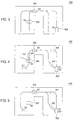
- Figure 4 is an exemplary roadmap graph 400 depicting a solution for scheduling automated vehicles within a warehouse, such as the warehouse being depicted in Figure 3 , according to various embodiments.
- the first automated vehicle 302 commences the task at start position S1 (i.e., a rectangular area left of label "S1" on the roadmap graph 400) and picks up the item.
- the third automated vehicle 306 moves in order to complete the task as quickly as possible while the first automated vehicle 302 uses a joining path to reach a goal position G1 with two potential wait locations labeled W1.
- the start position S1 is also goal position G2 for the second automated vehicle 304. Accordingly, the second automated vehicle 304 moves to goal position G2 in order to pick up the next item with a wait location W2.
- the first automated vehicle 302 stops and waits for the second automated vehicle 304 to move to the goal position G2 and/or waits for the third automated vehicle 306 to move to goal position G3.
- the third automated vehicle 306 is located at start position S3 and constitutes an obstruction to the movement of the first automated vehicle 302 and must be moved out of the path.
- the second automated vehicle 304 is located at start position S2. While moving to the goal position G2, the second automated vehicle 304 waits, at wait location W2, for the first automated vehicle 302 to leave an area around the goal position G2, which is also labeled the start position S1.
- Figure 5 is an exemplary roadmap graph 300 depicting another solution for scheduling automated vehicles within a warehouse, such as the warehouse being depicted in Figure 3 , according to various embodiments.
- the other solution differs from the solution depicted in Figure 4 in several respects.
- a coordinated path planner that is configured according to this solution assigns a higher cost for starting an automated vehicle.
- the first automated vehicle 302 commences the task at start position S1 and picks up the item. While the first automated vehicle 302 uses a joining path to reach a goal position G1 with a potential wait location labeled W1, the second automated vehicle 304 moves from start position S2 and moves to goal position G2, which is also the start position S1. Even though the first automated vehicle 302 has to travel slightly longer in time, the third automated vehicle 306 does not have to start up, which results in significant cost savings. The third automated vehicle 306 does not need to move from position S3 in order to complete the task as quickly as possible.
- Figure 6A-C illustrate various levels of a multi-level graph 600 for efficient scheduling of multiple non-holonomic automated vehicles using coordinated path planning according to various embodiments.
- Figures 6A-C depict path planning between a start position 602 and a goal position 604 by determining optimal local paths between various high-level nodes, such as a high-level node 606 and a high-level node 608.
- Figure 6A and Figure 6B may be referred to as high-level graphs and Figure 6C may be referred to as a base roadmap graph. It is appreciated that several higher level graphs may be used for coordinated path planning. For example, larger environments may require more than two higher level graphs and one base roadmap graph.
- a coordinated path planner determines the optimal local paths between one or more connection nodes, which are nodes located on a periphery of the high-level nodes.
- the coordinated path planner may determine a path between connection nodes 610 as illustrated in Figure 6B .
- Such an optimal local path may connect one or more roadmap nodes (e.g., the roadmap node 206 of Figure 2 ), which are located inside each high-level node.
- the coordinated path planner computes an optimal local path that does not go through at least one roadmap node.
- a local path is determined between the start position 602 and a local connection node (e.g., a start connection node).
- a local connection node e.g., a start connection node
- such a path includes one or more inner roadmap nodes.
- the coordinated path planner 104 may compute a second local path between the goal position 604 and a local connection node (e.g., an end connection node, such as the end connection node 212 of Figure 2 ) in a similar manner.
- the coordinated path planner combines the local paths to form a final path 612 on the multi-level graph 600 as illustrated in Figure 6C .
- the coordinated path planner 104 selects a lowest cost path that includes these local paths and high level paths to the local connection node associated with the goal position 604.
- Optimal high-level paths within the high-level node 606 and the high-level node 608 are then computed. These paths may not necessarily match with any portion of the lowest cost path because of various factors, such as other vehicles operating at or around a same time.
- the coordinated path planner 104 determines an optimal path at a lowest-level (i.e., a roadmap-level)
- the coordinated path planner 104 returns this result as the final path 612 according to one or more embodiments.
- FIG. 7 is a structural block diagram of a system 700 for efficient scheduling for multiple automated non-holonomic vehicles using a coordinated path planner, such as the coordinated path planner 104, according to one or more embodiments.
- the system 700 includes a computer 702 and a plurality of vehicles 704 (illustrated as a vehicle 704 1 ... a vehicle 704 N ) in which each component is coupled to each other through a network 706.
- Each of the plurality of vehicles 704 includes a navigation module, such as the navigation module 108, for operating various vehicle components, such as steering and/or motion components. It is appreciated that the plurality of vehicles 704 may utilize one or more computers for executing the navigation module 108.
- the computer 702 is a type of computing device (e.g., a laptop, a desktop, a Personal Desk Assistant (PDA) and the like).
- Each of the vehicles 704 includes a type of computing device (e.g., a laptop computer, a desktop computer, a Personal Desk Assistant (PDA) and the like).
- a computing device generally, comprises a central processing unit (CPU) 708, various support circuits 710 and a memory 712.
- the CPU 708 may comprise one or more commercially available microprocessors or microcontrollers that facilitate data processing and storage.
- Various support circuits 710 facilitate operation of the CPU 708 and may include clock circuits, buses, power supplies, input/output circuits and/or the like.
- the memory 712 includes a read only memory, random access memory, disk drive storage, optical storage, removable storage, and the like.
- the memory 712 includes various data, such as the map 110, as well as various software packages, such as the coordinated path planner 104, the schedule 106 and the navigation module 108. These software packages implement an apparatus, such as the apparatus 100 of Figure 1 , for efficient scheduling of the automated vehicles 704.
- the coordinated path planner 104 includes software code (e.g., processor executable instructions) that is executed by the CPU in order to respond to queries from the scheduler 106 as described in the present disclosure.
- the coordinated path planner 104 determines time estimates for each and every possible solution for completing a task. These time estimates are used for evaluating the possible solutions.
- the scheduler 106 selects a solution for scheduling the automated vehicles 704 evaluated against a heuristic.
- the scheduler 106 communicates instructions (e.g., a schedule) to the traffic manager 110, which uses the navigation module 108 to control automated vehicle operations and movements.
- the network 706 comprises a communication system that connects computers by wire, cable, fiber optic, and/or wireless links facilitated by various types of well-known network elements, such as hubs, switches, routers, and the like.
- the network 706 may employ various well-known protocols to communicate information amongst the network resources.
- the network 706 may be part of the Internet or intranet using various communications infrastructure such as Ethernet, WiFi, WiMax, General Packet Radio Service (GPRS), and the like.
- GPRS General Packet Radio Service
Description
- Embodiments of the present disclosure generally relate to a vehicle management system and, more particularly, to a method and apparatus for efficient scheduling for multiple automated non-holonomic vehicles using a coordinated path planner.
- Automated Vehicles (AVs) operate in mixed-use, multivehicle, dynamic warehouse environments. The nature of this environment can cause automated vehicles to become impeded by unknown obstacles or situations as they go about the execution of tasks. This delay causes any a priori planning to become obsolete as the interaction of automated vehicles may cause deadlocks, and time critical tasks become at risk for completion. Factors including overall driving time, vehicle constraints such as non-holonomic motion and fuel usage also impact planning. These problems have motivated the development and implementation of the presented scheduling solution using coordinated paths for multiple vehicles.
- Although research into multi-vehicle path planning is not a new topic, for example, a coordinated approached is used in constraining robots to defined roadmaps resulting in a complete and relatively fast solution, a near-optimal multi-vehicle approach for non-holonomic vehicles focuses on continuous curve paths that avoid moving obstacles and are collision free is not available. Even though these solutions are useful, the problem consideration is not broad enough to be used directly within the targeted industrial environment. There may be requirements to have high utilization of resources and throughput of product. Current approaches used to solve the planning and scheduling problem, particularly with multiple vehicles have often been too limited in scope to address and attempt to optimize solutions.
-
US 5,283,739 A describes a method of static collision avoidance for multiple automatically guided vehicles (AGVs) on bidirectional paths. -
US 6,285,951 B1 describes a method and system is disclosed for dynamically routing a material transport vehicle using traffic based parameters. - Jacob Jay Thomson et al. "Efficient scheduling for multiple automated non-holonomic vehicles using a coordinated path planner", XP032034390 describes scheduling and planning solutions for operating automated vehicles in warehouse environments.
- Therefore, there is a need in the art for a method and apparatus for efficient scheduling of multiple non-holonomic automated vehicles using coordinated path planning.
- The invention provides a method for coordinating path planning for a plurality of automated vehicles, the method comprising providing a multi-level graph comprising high-level nodes corresponding to an area, wherein each of the high-level nodes comprises one or more connection nodes corresponding to a periphery of the area, one or more roadmap nodes corresponding to the inside of the area, and one or more local paths that link the connection nodes, the roadmap nodes, or a combination thereof of a given area; constructing, offline, a solution set of roadmap graphs from the multi-level graph, wherein each of the roadmap graphs comprises a start position within one of the high-level nodes linked via a final path to a goal position within another of the high-level nodes, and wherein the final path comprises a selection of the local paths of the high-level nodes; evaluating each of the roadmap graphs against a heuristic, wherein the heuristic is used to select the final path of its associated roadmap graph; selecting, online and automatically with one or more computers, a coordinated path plan for the automated vehicles from the solution set of roadmap graphs, wherein the coordinated path plan is selected based upon the heuristic; and operating the automated vehicles according to the coordinated path plan.
- So that the manner in which the above recited features of the present invention can be understood in detail, a more particular description of the invention, briefly summarized above, may be had by reference to embodiments, some of which are illustrated in the appended drawings. It is to be noted, however, that the appended drawings illustrate only typical embodiments of this invention and are therefore not to be considered limiting of its scope, for the invention may admit to other equally effective embodiments.
-
Figure 1 is a functional block diagram illustrating an apparatus for efficient scheduling of automated vehicles using a map and implementing a coordinated path planner according to various embodiments; -
Figure 2 illustrates a multi-level graph for performing coordinated path planning of an automated vehicle according to various embodiments; -
Figure 3 is an exemplary roadmap graph illustrating a warehouse comprising automated vehicles according to various embodiments; -
Figure 4 is an exemplary roadmap graph depicting a scheduling solution for automated vehicles within a warehouse according to various embodiments; -
Figure 5 is an exemplary roadmap graph depicting another scheduling solution for automated vehicles within a warehouse according to various embodiments; -
Figures 6A-C illustrate various levels of a multi-level graph for efficient scheduling of multiple non-holonomic automated vehicles using coordinated path planning according to various embodiments; and -
Figure 7 is a block diagram illustrating a system for efficient scheduling and path planning of automated vehicles using a map and implementing a coordinated path planner according to various embodiments. - Given a set of objectives, such as moving product around a warehouse, various embodiments of a method and apparatus for efficient scheduling of multiple non-holonomic automated vehicles using coordinated path planning finds a solution that optimizes resource utilization while meeting current and future task deadlines according to some embodiments. An objective can be defined for the optimization including terms for maneuvering speeds, fuel usage, and upcoming tasks locations. The speed at which planning solutions are found allows many different possibilities for current and future objectives to be evaluated enabling the best solution to be selected. Solutions for paths are also extended by using smooth, continuous curvature paths, to allow an automated vehicle to drive paths without having to stop.
- The present disclosure describes a multi-vehicle path planning and scheduling apparatus or system for non-holonomic automated vehicles. This apparatus been developed for use on automated vehicles (e.g., robots, automated forklifts and/or the like) for solving planning problems. Generally, non-holonomic (also referred to as anholonomic) include systems whose states are defined by paths that are used to arrive at the states.
- Planning time and scalability are critical factors for functional systems. To help reduce search space and solution calculation time a constraint for the total number of automated vehicles in a multi-level node is introduced. This limits search complexity with little negative impact since automated vehicles do not generally need to occupy the same area in the warehouse. Fast planning times has allowed forecast plans to be generated. Forecasting allows the scheduling component to spend more time finding an optimal solution without impacting the current movement automated vehicles. Forecasting also provides a level of visibility for completion of orders and helps to ensure that automated vehicle utilization is efficient not only for the current task but for up-coming tasks as well.
- Motivated by the flexible use of automated vehicles and the interaction with an environment (e.g., a warehouse), the present disclosure also describes coordinated path planning while allowing automated vehicles to drive on and/or off from a roadmap graph. This enables an automated vehicle to be turned on at any position and drive to the end of a path with enough accuracy to be able to correctly interact with the environment when carrying out tasks. Furthermore, because blocked paths can cause other path segments to also become blocked, preventing other automated vehicles from attempting to drive through that area improves resource utilization and saves a significant amount of travel time that would be otherwise wasted waiting for the area to clear or determining an alternate path that avoids the obstruction and the blocked path.
-
Figure 1 is a functional block diagram illustrating an apparatus 100 for efficient scheduling of automated vehicles using amap 102 and implementing a coordinatedpath planner 104 according to various embodiments. In addition to the coordinatedpath planner 104, the apparatus 100 implements various modules (e.g., software code, firmware, hardware components and/or the like), such as ascheduler 106, anavigation module 108 and atraffic manager 110. - In some embodiments, the
scheduler 106 queries the coordinatedpath planner 104 with different possible solutions for one or more available automated vehicles (AVs) performing various available tasks. Thescheduler 106 allocates these tasks to the automated vehicles more effectively by examining results of the possible solutions that are provided from the coordinatedpath planner 104. Once a decision is made as to which solution to execute, thescheduler 106 communicates a coordinated plan to thetraffic manager 110 to manage and/or monitor the execution by the automated vehicles. Thetraffic manager 110 ensures that the automated vehicles perform the allocated tasks in accordance with the coordinated plan. Each automated vehicle includes thenavigation module 108 for controlling vehicle movement (i.e., driving) and performing localization. Thetraffic manager 110 controls the travel distance based on a current execution state. As new information becomes available, such as changes to themap 102 or new tasks to consider, thescheduler 106 continues to find better solutions and reroute the automated vehicles along various paths. - Finding the best solution requires the
scheduler 106 to query the coordinatedpath planner 104 regarding each and every possible solution for each of the available tasks by different automated vehicles. Thescheduler 106 processes results for each solution and searches for the solution that closely satisfies the heuristic. A satisfactory run-time performance may be achieved by applying thresholds to the results and/or selecting the best solution within a given time period. Improving run-time performance prevents various problems, such as delays caused by idling, wasting of resources and/or missing deadlines. - The
scheduler 106 forecasts future solutions based on information about up-coming tasks according to some embodiments. During planning for an automated vehicle, another automated vehicle moves to a location and blocks an area for an estimated amount of time while executing some aspect of a current task. Such an estimated amount of time is taken into account during path planning and scheduling. Once the time estimate elapses, the other automated vehicle may drive to a different location. As a result, task execution by the automated vehicle does not conflict with the execution of the current task by the other automated vehicle. Identifying and avoiding problematic situations (e.g., positions that are inescapable) improves time efficiencies and utilization in the long run. - In response to a query from the
scheduler 106, the coordinatedpath planner 104 returns time estimates for each possible configuration of one or more automated vehicles. Various factors can influence each time estimate. For example, allocating an automated vehicle to a task may adversely impact other automated vehicles that are also completing tasks or are idle. Because starting idle automated vehicles costs time and resources (e.g., fuel), thescheduler 106 uses a heuristic that reflects such costs according to some embodiments. For example, thecoordinated path planner 104 adds terms that represent costs for starting idle automated vehicles. - The apparatus 100 may perform coordinated path planning continuously or periodically. In some embodiments, as tasks become available over time, the coordinated path planning is subsequently performed instead of all at once due to calculation time and limited information. Optionally, whenever an event occurs, such as a new task or a change to the
map 102, a current schedule becomes invalidated as there could potentially be a better solution. Scheduling, however, is not instantaneous and it would be inefficient to have the automated vehicles stop driving while a new plan is being calculated. In some embodiments, thescheduler 106 communicates a specific time to thetraffic manager 110 after which the automated vehicles will stop; thetraffic manager 110 also returns the estimated position of the automated vehicles at that time. - In the meantime, the
scheduler 106 performs path planning and scheduling from this time with the updated event. When the time is expired, thescheduler 106 selects the best solution discovered thus far, assuming such a solution is within a pre-defined threshold and updates the current schedule. If the threshold is not met, then further planning is necessary. If the event does not change the immediate plan, the automated vehicles continue executing tasks seamlessly. - In an industrial environment (e.g., a warehouse), various areas will often become unavailable for transiting due a number of reasons, such as automated vehicle malfunction or an obstruction (e.g., an obstacle that is not included in the map 102). As explained in detail further below, because a size of the search space (e.g., a supergraph comprising each and every configuration of automated vehicles as explained further below) precludes making changes online whenever there are changes to the
map 102, a list of blocked nodes are recorded instead. Thecoordinated path planner 104 examines such a list when performing path planning in order to stop different automated vehicles from path planning and/or navigating paths through these areas. If it is known that the same nodes are going to be blocked for a while, then the offline measurements against the heuristic are recalculated according to some embodiments. - Instead of using standard Dubins paths for non-holonomic automated vehicles, the
coordinated path planner 104 modifies Dubins paths to add transitioning periods of constant change in curvature. A continuous change in curvature path is desired to allow the automated vehicle to drive accurately at a higher speed. In some embodiments, the apparatus 100 implements the modified Dubins paths by constructing graph segments and joining paths out of smooth paths. The joining paths can have sharper turns at the ends and smoother turns where the joining paths join the graph as the automated vehicle will be going faster once the automated vehicle hits the graph. Because of the extra space that these paths require, the joining of the joining paths need to be repeated with sharper path segments if the joining fail on smoother ones. -
Figure 2 illustrates amulti-level graph 200 for performing coordinated path planning of an automated vehicle according to various embodiments. Thecoordinated path planner 104 considers each and every automated vehicle together as one composite unit with one or more degrees of freedom. Starting positions of the automated vehicles are one configuration of this unit and goal positions are another configuration. Each configuration may constitute a state in a non-holonomic system. - As illustrated, the
multi-level graph 200 defines astart position 202 and agoal position 204 for the composite unit of one or more automated vehicles. A total number of possible configurations are limited by discretizing themulti-level graph 200 into a roadmap graph as explained in detail further below. The movement of the one or more automated vehicles may be represented as a series of configurations. Each configuration defines positions for the one or more automated vehicles, which may include one or more roadmap nodes, such as aroadmap node 206, one or more connection nodes on a high-level node, such as a high-level node 208. A configuration may correspond to another configuration when the one or more automated vehicles move between connected roadmap nodes as long as these movements do not result in a collision. - In some embodiments, the
coordinated path planner 104 places various types of nodes throughout the map and then, joins these nodes using path segments forming a roadmap graph. The various types of nodes include, but are not limited to, theroadmap node 206, the high-level node 208, aconnection node 210 and anend connection node 212. The path segments connecting various ones of the nodes include, but are not limited to, apath 214 and apath 216. The automated vehicles move from node to node along the path segments until the automated vehicles reach thegoal position 204. - The
coordinated path planner 104, in an offline process, forms high-level nodes using all of the possible combinations or configurations of the automated vehicles at different roadmap nodes. These high-level nodes are connected by moving one automated vehicle along a connected path segment to reach another high-level node. Thecoordinated path planner 104 uses various computation techniques (e.g., supergraph computation techniques) to remove any unfeasible solutions. In some embodiments, the high-level nodes and associated connections form a supergraph. Hence, the supergraph includes each and every automated vehicle configuration within themulti-level graph 200. By traversing the supergraph at runtime, thescheduler 106 searches for the best solution to path planning without having to do any intersection calculations, which were performed offline. - In some embodiments, the
coordinated path planner 104 uses a heuristic for searching themulti-level graph 200 for the best solution (i.e., path). For example, the heuristic may be a travel time of automated vehicles between nodes. Estimates of travel times can be established offline and summed for all of the automated vehicles operating at a particular schedule. Thecoordinated path planner 104 repeats the path planning process leading to the selection of the best solution when compared with the heuristic. - In some embodiments involving large areas with several automated vehicles, the
coordinated path planner 104 utilizes a multi-level graph, such as themulti-level graph 200, in order to reduce a size of a search space. Thecoordinated path planner 104 groups various nodes, such as roadmap nodes and connections nodes, into higher level nodes as illustrated. A solution is first found for a higher level portion of themulti-level graph 200, followed by a more specific solution for the next level down until a complete roadmap-level path is finalized. - The search space is further reduced by constraining the number of automated vehicles within high-level nodes. This constraint is possible given the industrial environment layouts which often can only effectively allow one or two automated vehicles in a given area. The
multi-level graph 200 will result in a less optimal solution as it assumes the best high level search will contain the best lower level search, this is a tradeoff for calculation time. Measurements for evaluation against the heuristic may be computed offline for themulti-level graph 200. - In some embodiments with high vehicle traffic, the solution found by the coordinated
path planner 104 will resolve such issues by requiring one or more automated vehicles to wait until other vehicles to pass specific locations. Such resolutions are noted in the plan as dependencies between vehicles with the corresponding locations. Thetraffic manager 110 interprets these dependencies while the solution is executed, and ensures the vehicles adhere to these dependencies when determining the distances vehicles are permitted to drive. - In some embodiments, the automated vehicles will not always start off or finish on a position on the
path 216. This occurs when automated vehicles are manually driven and start anywhere within the known area or need to engage with items placed by human drivers who do not place items on themulti-level graph 200. To solve this problem, for each automated vehicle, a path from the start position to a node and a path from a node to thegoal position 204 needs to be calculated. As long as there is sufficient coverage of the roadmap, then a Dubins path or similar path will suffice. - There may be several options of nodes to join, and the closest node may not necessarily be the optimum. An important advantage of the approach described in the present disclosure is that calculation speed allows determination of near optimum join locations. It may also be more efficient to join along a roadmap edge rather than at a node. In order to narrow down the joining possibilities for an automated vehicle, a grid can be calculated offline that will contain possible nodes that can be reached from within each grid square. At runtime the possible nodes are retrieved and a binary scan is performed along their connecting path segments to determine the best place to join. The top path segments are chosen as options for the search, the node at the end of the segment is used. These graph joining paths should be chosen such that they do not intersect the start/goal positions or the start/goal nodes of other automated vehicles, this will allow them to reach their initial node and leave their last node without causing a deadlock. Calculating the joiners does mean there will be some intersection calculations at run time but the areas are small and can be resolved quickly if the
map 102 is broken down into a quad-tree. -
Figure 3 is anexemplary roadmap graph 300 illustrating a warehouse comprising automated vehicles according to various embodiments. - The
roadmap graph 300 depicts three automated vehicles whose task is to pick up items from a right side of a map and transport the picked up items to a left side according to some embodiments. A firstautomated vehicle 302 picks up an item, which must be returned to the other side of the warehouse. Subsequently, one of the other two automated vehicles is to come and pick up a next item on the right side. There are at least two solutions for the scheduler 106: use a secondautomated vehicle 304 or a thirdautomated vehicle 306 to pick up the item. All of the possible solutions, along with moving the firstautomated vehicle 302 to the left, are communicated to the coordinatedpath planner 104 where paths with estimated times to completion are computed.Table I ESTIMATED TIMES USING DIFFERENT AUTOMATED VEHICLES Estimated Travel Times AV 302 AV 304AV 306AV chosen for right pick up AV 30434.13 19.43 5.76 AV 30636.30 10.11 44.74 - The resulting time estimates are shown in Table I, the second
automated vehicle 304 is favored for the task as it is closer and is blocking the corridor. This solution is described with respect toFigure 4 . Because starting up idle automated vehicles may be undesirable, a cost is applied to this activity in some embodiments. This solution is described with respect toFigure 5 . - In some embodiments, the
coordinated path planner 104 and thescheduler 106 account for instances where an automated vehicle must wait for another automated vehicle. Wait positions and time estimates are computed for these instances and incorporated into path planning and scheduling, as described with respect toFigure 4 and Figure 5 . Continuous curvature paths are used inFigures 4 and 5 on the roadmap graph and the joining paths. The joining paths are sharper at the ends as the automated vehicles are traveling slower. - Table II depicts estimated travel times for the first
automated vehicle 302, the secondautomated vehicle 304 and the thirdautomated vehicle 306 that take into account a time spent turning on an automated vehicle.Table II Estimated Travel Times AV 302 AV 304AV 30639.78 19.43 0.00 -
Figure 4 is anexemplary roadmap graph 400 depicting a solution for scheduling automated vehicles within a warehouse, such as the warehouse being depicted inFigure 3 , according to various embodiments. The firstautomated vehicle 302 commences the task at start position S1 (i.e., a rectangular area left of label "S1" on the roadmap graph 400) and picks up the item. The thirdautomated vehicle 306 moves in order to complete the task as quickly as possible while the firstautomated vehicle 302 uses a joining path to reach a goal position G1 with two potential wait locations labeled W1. - As depicted on the
roadmap graph 400, the start position S1 is also goal position G2 for the secondautomated vehicle 304. Accordingly, the secondautomated vehicle 304 moves to goal position G2 in order to pick up the next item with a wait location W2. In some embodiments, the firstautomated vehicle 302 stops and waits for the secondautomated vehicle 304 to move to the goal position G2 and/or waits for the thirdautomated vehicle 306 to move to goal position G3. In some embodiments, the thirdautomated vehicle 306 is located at start position S3 and constitutes an obstruction to the movement of the firstautomated vehicle 302 and must be moved out of the path. In other embodiments, the secondautomated vehicle 304 is located at start position S2. While moving to the goal position G2, the secondautomated vehicle 304 waits, at wait location W2, for the firstautomated vehicle 302 to leave an area around the goal position G2, which is also labeled the start position S1. -
Figure 5 is anexemplary roadmap graph 300 depicting another solution for scheduling automated vehicles within a warehouse, such as the warehouse being depicted inFigure 3 , according to various embodiments. In some embodiments, the other solution differs from the solution depicted inFigure 4 in several respects. For example, a coordinated path planner that is configured according to this solution assigns a higher cost for starting an automated vehicle. The firstautomated vehicle 302 commences the task at start position S1 and picks up the item. While the firstautomated vehicle 302 uses a joining path to reach a goal position G1 with a potential wait location labeled W1, the secondautomated vehicle 304 moves from start position S2 and moves to goal position G2, which is also the start position S1. Even though the firstautomated vehicle 302 has to travel slightly longer in time, the thirdautomated vehicle 306 does not have to start up, which results in significant cost savings. The thirdautomated vehicle 306 does not need to move from position S3 in order to complete the task as quickly as possible. -
Figure 6A-C illustrate various levels of amulti-level graph 600 for efficient scheduling of multiple non-holonomic automated vehicles using coordinated path planning according to various embodiments.Figures 6A-C depict path planning between astart position 602 and agoal position 604 by determining optimal local paths between various high-level nodes, such as a high-level node 606 and a high-level node 608.Figure 6A and Figure 6B may be referred to as high-level graphs andFigure 6C may be referred to as a base roadmap graph. It is appreciated that several higher level graphs may be used for coordinated path planning. For example, larger environments may require more than two higher level graphs and one base roadmap graph. - In some embodiments, a coordinated path planner determines the optimal local paths between one or more connection nodes, which are nodes located on a periphery of the high-level nodes. The coordinated path planner may determine a path between
connection nodes 610 as illustrated inFigure 6B . Such an optimal local path may connect one or more roadmap nodes (e.g., theroadmap node 206 ofFigure 2 ), which are located inside each high-level node. In other embodiments, the coordinated path planner computes an optimal local path that does not go through at least one roadmap node. - Subsequently, a local path is determined between the
start position 602 and a local connection node (e.g., a start connection node). In some embodiments, such a path includes one or more inner roadmap nodes. Thecoordinated path planner 104 may compute a second local path between thegoal position 604 and a local connection node (e.g., an end connection node, such as theend connection node 212 ofFigure 2 ) in a similar manner. In some embodiments, the coordinated path planner combines the local paths to form afinal path 612 on themulti-level graph 600 as illustrated inFigure 6C . In some embodiments, thecoordinated path planner 104 selects a lowest cost path that includes these local paths and high level paths to the local connection node associated with thegoal position 604. Optimal high-level paths within the high-level node 606 and the high-level node 608 are then computed. These paths may not necessarily match with any portion of the lowest cost path because of various factors, such as other vehicles operating at or around a same time. Once thecoordinated path planner 104 determines an optimal path at a lowest-level (i.e., a roadmap-level), thecoordinated path planner 104 returns this result as thefinal path 612 according to one or more embodiments. -
Figure 7 is a structural block diagram of a system 700 for efficient scheduling for multiple automated non-holonomic vehicles using a coordinated path planner, such as thecoordinated path planner 104, according to one or more embodiments. In some embodiments, the system 700 includes acomputer 702 and a plurality of vehicles 704 (illustrated as a vehicle 7041... a vehicle 704N) in which each component is coupled to each other through anetwork 706. Each of the plurality of vehicles 704 includes a navigation module, such as thenavigation module 108, for operating various vehicle components, such as steering and/or motion components. It is appreciated that the plurality of vehicles 704 may utilize one or more computers for executing thenavigation module 108. - The
computer 702 is a type of computing device (e.g., a laptop, a desktop, a Personal Desk Assistant (PDA) and the like). Each of the vehicles 704 includes a type of computing device (e.g., a laptop computer, a desktop computer, a Personal Desk Assistant (PDA) and the like). A computing device, generally, comprises a central processing unit (CPU) 708,various support circuits 710 and amemory 712. The CPU 708 may comprise one or more commercially available microprocessors or microcontrollers that facilitate data processing and storage.Various support circuits 710 facilitate operation of the CPU 708 and may include clock circuits, buses, power supplies, input/output circuits and/or the like. Thememory 712 includes a read only memory, random access memory, disk drive storage, optical storage, removable storage, and the like. Thememory 712 includes various data, such as themap 110, as well as various software packages, such as thecoordinated path planner 104, theschedule 106 and thenavigation module 108. These software packages implement an apparatus, such as the apparatus 100 ofFigure 1 , for efficient scheduling of the automated vehicles 704. - In some embodiments, the
coordinated path planner 104 includes software code (e.g., processor executable instructions) that is executed by the CPU in order to respond to queries from thescheduler 106 as described in the present disclosure. Thecoordinated path planner 104 determines time estimates for each and every possible solution for completing a task. These time estimates are used for evaluating the possible solutions. In some embodiments, thescheduler 106 selects a solution for scheduling the automated vehicles 704 evaluated against a heuristic. Thescheduler 106 communicates instructions (e.g., a schedule) to thetraffic manager 110, which uses thenavigation module 108 to control automated vehicle operations and movements. - The
network 706 comprises a communication system that connects computers by wire, cable, fiber optic, and/or wireless links facilitated by various types of well-known network elements, such as hubs, switches, routers, and the like. Thenetwork 706 may employ various well-known protocols to communicate information amongst the network resources. For example, thenetwork 706 may be part of the Internet or intranet using various communications infrastructure such as Ethernet, WiFi, WiMax, General Packet Radio Service (GPRS), and the like. - While the foregoing is directed to embodiments of the present invention, other and further embodiments of the invention may be devised without departing from the basic scope thereof, and the scope thereof is determined by the claims that follow.
Claims (15)
- A method for coordinating path planning for a plurality of automated vehicles, the method comprising:providing a multi-level graph (200) comprising high-level nodes (208) corresponding to an area, wherein each of the high-level nodes (208) comprises one or more connection nodes (210) corresponding to a periphery of the area, one or more roadmap nodes (206) corresponding to the inside of the area, and one or more local paths that link the connection nodes (210), the roadmap nodes (206), or a combination thereof of a given area;constructing, offline, a solution set of roadmap graphs (300) from the multi-level graph (200), wherein each of the roadmap graphs (300) comprises a start position (202) within one of the high-level nodes (208) linked via a final path to a goal position (204) within another of the high-level nodes (208), and wherein the final path comprises a selection of the local paths of the high-level nodes (208);evaluating each of the roadmap graphs (300) against a heuristic, wherein the heuristic is used to select the final path of its associated roadmap graph (300);selecting, online and automatically with one or more computers, a coordinated path plan for the automated vehicles from the solution set of roadmap graphs (300), wherein the coordinated path plan is selected based upon the heuristic; andoperating the automated vehicles according to the coordinated path plan.
- The method of claim 1, further comprising removing an unfeasible solution from the solution set of roadmap graphs (300).
- The method of claim 1, further comprising constraining the number of automated vehicles within the high-level nodes (208).
- The method of claim 3, wherein the number of automated vehicles is constrained to one or two.
- The method of claim 1, further comprising stopping a first automated vehicle of the automated vehicles at a wait location (W1), when a second automated vehicle of the automated vehicles constitutes an obstruction to the movement of the first automated vehicle.
- The method of claim 1, further comprising:recording a list of blocked nodes; andstopping the automated vehicles from path planning and/or navigating through the area corresponding to the blocked nodes.
- The method of claim 1, further comprising forming a modified Dubins path by constructing graph segments and joining paths out of smooth paths, wherein the joining paths can have sharper turns at the ends and smoother turns where the joining paths join the graph.
- The method of claim 1, further comprising:calculating, offline, a grid comprising grid squares that each comprise possible nodes of the roadmap nodes (206);retrieving the possible nodes of the grid squares; andperforming a binary scan along their connecting path segments to determine the best place to join.
- The method of claim 8, wherein the joining path does not intersect with the start position (202) and the goal position (204) or the start node and the goal node of other automated vehicles.
- The method of claim 1, wherein the coordinated path plan requires one of the automated vehicles to wait until another of the automated vehicles passes a specific location.
- The method of claim 1, wherein the heuristic is a travel time.
- The method of claim 1, wherein the heuristic reflects a cost of starting up an idled vehicle of the automated vehicles.
- The method of claim 1 wherein the one or more automated vehicles are non-holonomic.
- The method of claim 1, wherein the selection of the local paths of the high-level nodes (208) is combined to form the final path.
- The method of claim 1, wherein the coordinated path is selected by first finding the high-level nodes (208) and subsequently combining the local paths of the high-level nodes.
Priority Applications (1)
| Application Number | Priority Date | Filing Date | Title |
|---|---|---|---|
| EP18189110.2A EP3435189B1 (en) | 2011-04-11 | 2012-04-10 | Apparatus for efficient scheduling for multiple automated non-holonomic vehicles using a coordinated path planner |
Applications Claiming Priority (2)
| Application Number | Priority Date | Filing Date | Title |
|---|---|---|---|
| US201161474030P | 2011-04-11 | 2011-04-11 | |
| PCT/NZ2012/000051 WO2012141601A2 (en) | 2011-04-11 | 2012-04-10 | Method and apparatus for efficient scheduling for multiple automated non-holonomic vehicles using a coordinated path planner |
Related Child Applications (2)
| Application Number | Title | Priority Date | Filing Date |
|---|---|---|---|
| EP18189110.2A Division EP3435189B1 (en) | 2011-04-11 | 2012-04-10 | Apparatus for efficient scheduling for multiple automated non-holonomic vehicles using a coordinated path planner |
| EP18189110.2A Division-Into EP3435189B1 (en) | 2011-04-11 | 2012-04-10 | Apparatus for efficient scheduling for multiple automated non-holonomic vehicles using a coordinated path planner |
Publications (3)
| Publication Number | Publication Date |
|---|---|
| EP2697701A2 EP2697701A2 (en) | 2014-02-19 |
| EP2697701A4 EP2697701A4 (en) | 2014-10-01 |
| EP2697701B1 true EP2697701B1 (en) | 2018-10-24 |
Family
ID=47009885
Family Applications (2)
| Application Number | Title | Priority Date | Filing Date |
|---|---|---|---|
| EP12770733.9A Active EP2697701B1 (en) | 2011-04-11 | 2012-04-10 | Method and apparatus for efficient scheduling for multiple automated non-holonomic vehicles using a coordinated path planner |
| EP18189110.2A Active EP3435189B1 (en) | 2011-04-11 | 2012-04-10 | Apparatus for efficient scheduling for multiple automated non-holonomic vehicles using a coordinated path planner |
Family Applications After (1)
| Application Number | Title | Priority Date | Filing Date |
|---|---|---|---|
| EP18189110.2A Active EP3435189B1 (en) | 2011-04-11 | 2012-04-10 | Apparatus for efficient scheduling for multiple automated non-holonomic vehicles using a coordinated path planner |
Country Status (9)
| Country | Link |
|---|---|
| US (2) | US9188982B2 (en) |
| EP (2) | EP2697701B1 (en) |
| KR (1) | KR102041093B1 (en) |
| CN (2) | CN107272678B (en) |
| AU (1) | AU2012243484B2 (en) |
| BR (1) | BR112013026178A2 (en) |
| CA (1) | CA2831832C (en) |
| RU (1) | RU2589869C2 (en) |
| WO (1) | WO2012141601A2 (en) |
Families Citing this family (79)
| Publication number | Priority date | Publication date | Assignee | Title |
|---|---|---|---|---|
| WO2014155731A1 (en) * | 2013-03-29 | 2014-10-02 | 三菱重工業株式会社 | On-board device, signal system, and control method for traveling device |
| GB201310784D0 (en) | 2013-06-17 | 2013-07-31 | Ocado Ltd | Systems and Methods for Order Processing |
| DE102013010787A1 (en) * | 2013-06-28 | 2014-12-31 | Servus Intralogistics Gmbh | Control system for a rail-bound driving robot and method for its operation |
| US10201022B2 (en) * | 2013-07-10 | 2019-02-05 | Agco Corporation | Automation of networking a group of machines |
| US10180328B2 (en) * | 2013-07-10 | 2019-01-15 | Agco Coporation | Automating distribution of work in a field |
| GB201314313D0 (en) | 2013-08-09 | 2013-09-25 | Ocado Ltd | Apparatus for retrieving units from a storage system |
| US11858738B2 (en) | 2013-08-09 | 2024-01-02 | Ocado Innovation Limited | Apparatus for retrieving units from a storage system |
| US9354070B2 (en) | 2013-10-31 | 2016-05-31 | Crown Equipment Corporation | Systems, methods, and industrial vehicles for determining the visibility of features |
| CN103676944B (en) * | 2013-12-11 | 2016-11-23 | 北京理工大学 | The unmanned aerial vehicle flight path planing method searched for based on Dubins path and sparse A* |
| US10127514B2 (en) * | 2014-04-11 | 2018-11-13 | Intelligrated Headquarters Llc | Dynamic cubby logic |
| GB201409883D0 (en) | 2014-06-03 | 2014-07-16 | Ocado Ltd | Methods, systems, and apparatus for controlling movement of transporting devices |
| EP3161573B1 (en) | 2014-06-27 | 2020-02-26 | Crown Equipment Corporation | Vehicle positioning or navigation utilizing associated feature pairs |
| WO2016048698A1 (en) | 2014-09-22 | 2016-03-31 | Sikorsky Aircraft Corporation | Coordinated planning with graph sharing over networks |
| CN105811085B (en) * | 2014-12-30 | 2020-09-08 | 上海伯乐电子有限公司 | Flexible RFID antenna and POS machine device and electronic equipment applying same |
| CN107980100B (en) | 2015-03-07 | 2022-05-27 | 维里蒂工作室股份公司 | Distributed positioning system and method and self-positioning equipment |
| DE102015006014A1 (en) * | 2015-05-13 | 2016-11-17 | Universität Bielefeld | Soil cultivation device and method for its navigation and swarm of tillage equipment and methods for their joint navigation |
| US10111044B2 (en) | 2015-05-29 | 2018-10-23 | Verity Studios Ag | Methods and systems for scheduling the transmission of localization signals and operating self-localizing apparatus |
| US9945677B1 (en) * | 2015-07-23 | 2018-04-17 | X Development Llc | Automated lane and route network discovery for robotic actors |
| SE542284C2 (en) * | 2015-10-01 | 2020-04-07 | Epiroc Rock Drills Ab | Method and system for assigning tasks to mining and/or construction machines |
| US9858819B2 (en) | 2016-02-03 | 2018-01-02 | Caterpillar Inc. | Traffic control system having deadlock avoidance functionality |
| US10144453B2 (en) | 2016-04-13 | 2018-12-04 | Cnh Industrial America Llc | System and method for controlling a vehicle |
| DE112017002156B4 (en) * | 2016-04-25 | 2020-11-26 | Lg Electronics Inc. | MOBILE ROBOT, SYSTEM FOR MULTIPLE MOBILE ROBOTS, AND CARD LEARNING PROCEDURE FOR MOBILE ROBOTS |
| US10296862B1 (en) * | 2016-05-12 | 2019-05-21 | Northrop Grumman Systems Corporation | Time interval assessment of mission plan quality dynamic asset allocation |
| CN109641589B (en) * | 2016-06-14 | 2023-10-13 | 动态Ad有限责任公司 | Route planning for autonomous vehicles |
| US10126136B2 (en) | 2016-06-14 | 2018-11-13 | nuTonomy Inc. | Route planning for an autonomous vehicle |
| US10309792B2 (en) | 2016-06-14 | 2019-06-04 | nuTonomy Inc. | Route planning for an autonomous vehicle |
| US11092446B2 (en) | 2016-06-14 | 2021-08-17 | Motional Ad Llc | Route planning for an autonomous vehicle |
| US10829116B2 (en) | 2016-07-01 | 2020-11-10 | nuTonomy Inc. | Affecting functions of a vehicle based on function-related information about its environment |
| DE102016009255B4 (en) * | 2016-07-29 | 2023-01-26 | Kuka Roboter Gmbh | Coordination of paths of multiple moving machines |
| US10037029B1 (en) | 2016-08-08 | 2018-07-31 | X Development Llc | Roadmap segmentation for robotic device coordination |
| RU2637582C1 (en) * | 2016-09-14 | 2017-12-05 | Александр Юрьевич Климентьев | Automated system of vehicle route construction and adjustment |
| CN109791477A (en) | 2016-09-30 | 2019-05-21 | 史泰博公司 | Hybrid modular storage extraction system |
| US10683171B2 (en) | 2016-09-30 | 2020-06-16 | Staples, Inc. | Hybrid modular storage fetching system |
| US10589931B2 (en) | 2016-09-30 | 2020-03-17 | Staples, Inc. | Hybrid modular storage fetching system |
| CN106548247B (en) * | 2016-10-08 | 2021-07-09 | 浙江国自机器人技术有限公司 | Traffic control method of mobile robot system |
| US10331129B2 (en) | 2016-10-20 | 2019-06-25 | nuTonomy Inc. | Identifying a stopping place for an autonomous vehicle |
| US10857994B2 (en) | 2016-10-20 | 2020-12-08 | Motional Ad Llc | Identifying a stopping place for an autonomous vehicle |
| US10473470B2 (en) | 2016-10-20 | 2019-11-12 | nuTonomy Inc. | Identifying a stopping place for an autonomous vehicle |
| US10681513B2 (en) | 2016-10-20 | 2020-06-09 | nuTonomy Inc. | Identifying a stopping place for an autonomous vehicle |
| SG10201609375XA (en) * | 2016-11-09 | 2018-06-28 | Cyclect Electrical Eng Pte Ltd | Vehicle, system and method for remote convoying |
| WO2018094741A1 (en) * | 2016-11-28 | 2018-05-31 | 深圳市大疆创新科技有限公司 | Air route editing method and apparatus, and control device |
| US10296012B2 (en) | 2016-12-21 | 2019-05-21 | X Development Llc | Pre-computation of kinematically feasible roadmaps |
| US10480947B2 (en) * | 2016-12-21 | 2019-11-19 | X Development Llc | Boolean satisfiability (SAT) reduction for geometry and kinematics agnostic multi-agent planning |
| US10363657B2 (en) | 2016-12-23 | 2019-07-30 | X Development Llc | Multi-agent coordination under sparse networking |
| US10406687B2 (en) * | 2016-12-23 | 2019-09-10 | X Development Llc | Layered multi-agent coordination |
| US11614751B2 (en) * | 2017-01-23 | 2023-03-28 | Massachusetts Institute Of Technology | System for on-demand high-capacity ride-sharing via dynamic trip-vehicle assignment and related techniques |
| US11270371B2 (en) * | 2017-03-10 | 2022-03-08 | Walmart Apollo, Llc | System and method for order packing |
| CN115855022A (en) * | 2017-04-07 | 2023-03-28 | 辉达公司 | Performing autonomous path navigation using deep neural networks |
| KR101975658B1 (en) * | 2017-05-04 | 2019-05-07 | 우동진 | Method and apparatus for controlling vehicles |
| CN107368072A (en) * | 2017-07-25 | 2017-11-21 | 哈尔滨工大特种机器人有限公司 | A kind of AGV operation control systems and paths planning method that can configure based on map |
| CN111133275B (en) * | 2017-07-28 | 2022-04-01 | 克朗设备公司 | Materials handling vehicle and system and method for navigating materials handling vehicle |
| US10349011B2 (en) * | 2017-08-14 | 2019-07-09 | GM Global Technology Operations LLC | System and method for improved obstacle awareness in using a V2X communications system |
| JP7072581B2 (en) | 2017-09-18 | 2022-05-20 | バイドゥドットコム タイムズ テクノロジー (ベイジン) カンパニー リミテッド | Lane guidelines based on driving scenarios for route planning of self-driving vehicles |
| RU2692695C2 (en) * | 2017-10-18 | 2019-06-26 | федеральное государственное бюджетное образовательное учреждение высшего образования "Ижевский государственный технический университет имени М.Т. Калашникова" | Close-loop for lean manufacturing system and method of its application |
| US20190138880A1 (en) | 2017-11-03 | 2019-05-09 | Drishti Technologies, Inc. | Workspace actor selection systems and methods |
| US10648820B2 (en) * | 2018-01-03 | 2020-05-12 | Deere & Company | Methods and apparatus for assessing coordinate data |
| EP3588405A1 (en) * | 2018-06-29 | 2020-01-01 | Tata Consultancy Services Limited | Systems and methods for scheduling a set of non-preemptive tasks in a multi-robot environment |
| CN112424721A (en) | 2018-07-17 | 2021-02-26 | 克朗设备公司 | System and method for vehicle position calibration using rack leg identification |
| EP3830661A1 (en) | 2018-08-01 | 2021-06-09 | Crown Equipment Corporation | Systems and methods for warehouse environment speed zone management |
| US11084410B1 (en) | 2018-08-07 | 2021-08-10 | Staples, Inc. | Automated guided vehicle for transporting shelving units |
| US11590997B1 (en) | 2018-08-07 | 2023-02-28 | Staples, Inc. | Autonomous shopping cart |
| US11630447B1 (en) | 2018-08-10 | 2023-04-18 | Staples, Inc. | Automated guided vehicle for transporting objects |
| CN110621449B (en) * | 2018-08-14 | 2022-07-08 | 千叶工业大学 | Mobile robot |
| CN110929911A (en) * | 2018-09-20 | 2020-03-27 | 北京京东尚科信息技术有限公司 | Unmanned equipment path planning method and device |
| US11782446B2 (en) | 2018-11-22 | 2023-10-10 | Nec Corporation | Route planning apparatus, route planning method, and computer-readable recording medium |
| US11256269B2 (en) * | 2018-11-29 | 2022-02-22 | Robert Bosch Gmbh | Optimization of task completion in a facility |
| US11119487B2 (en) | 2018-12-31 | 2021-09-14 | Staples, Inc. | Automated preparation of deliveries in delivery vehicles using automated guided vehicles |
| US11180069B2 (en) | 2018-12-31 | 2021-11-23 | Staples, Inc. | Automated loading of delivery vehicles using automated guided vehicles |
| KR102583386B1 (en) | 2019-02-06 | 2023-10-05 | 크라운 이큅먼트 코포레이션 | Systems and methods for out-of-aisle location and vehicle position correction using rack leg identification |
| US11124401B1 (en) | 2019-03-31 | 2021-09-21 | Staples, Inc. | Automated loading of delivery vehicles |
| IL289694B2 (en) * | 2019-07-12 | 2023-12-01 | Murata Machinery Ltd | Traveling vehicle system and traveling vehicle control method |
| RU2751734C2 (en) * | 2019-12-30 | 2021-07-16 | Общество с ограниченной ответственностью "Яндекс Беспилотные Технологии" | Methods and processors for steering control of self-driving car |
| CN111103887B (en) * | 2020-01-14 | 2021-11-12 | 大连理工大学 | Multi-sensor-based multi-mobile-robot scheduling system design method |
| JP7328923B2 (en) * | 2020-03-16 | 2023-08-17 | 株式会社東芝 | Information processing device, information processing method, and computer program |
| CA3198075A1 (en) | 2020-10-05 | 2022-04-14 | Crown Equipment Corporation | Systems and methods for relative pose determination and field enforcement of materials handling vehicles using ultra-wideband radio technology |
| US20220163969A1 (en) * | 2020-11-20 | 2022-05-26 | Rapyuta Robotics Co., Ltd. | Systems and methods for optimizing route plans in an operating environment |
| CN112631232B (en) * | 2020-12-28 | 2022-04-22 | 北京星航机电装备有限公司 | Method and system for realizing scheduling control of automatic guided vehicle based on openTCS |
| CN112793562B (en) * | 2021-02-03 | 2023-02-28 | 武汉理工大学 | Automatic parking path planning and tracking control method, planning device, storage medium and computer equipment |
| CN113741454B (en) * | 2021-08-31 | 2023-06-23 | 浙江大学 | Multi-agent path planning method and system based on search |
Family Cites Families (269)
| Publication number | Priority date | Publication date | Assignee | Title |
|---|---|---|---|---|
| US4043418A (en) | 1975-11-06 | 1977-08-23 | Logisticon Inc. | Reverse direction guidance system for lift truck |
| JPS5266260U (en) | 1975-11-10 | 1977-05-17 | ||
| JPS5266260A (en) | 1975-12-01 | 1977-06-01 | Komatsu Ltd | Device for automatically controllig lifting of forks in a for lift tru ck |
| US4071740A (en) | 1976-05-26 | 1978-01-31 | Paul Gogulski | Mobile automated shopping system |
| DE3003287A1 (en) | 1979-02-05 | 1980-08-14 | Volvo Ab | SELF-DRIVING VEHICLE |
| JPS5839195A (en) | 1981-08-31 | 1983-03-07 | Mitsubishi Electric Corp | Master station device for remote supervisory and controlling device |
| US4483407A (en) | 1982-03-26 | 1984-11-20 | Hitachi, Ltd. | Variable configuration track laying vehicle |
| US4530056A (en) | 1982-10-28 | 1985-07-16 | Modular Automation Corp. | Automated guided vehicle system |
| JPS6067818A (en) | 1983-09-22 | 1985-04-18 | Hitachi Ltd | On-vehicle navigator |
| JPS6067818U (en) | 1983-10-14 | 1985-05-14 | 株式会社日本アルミ | Cutting machine |
| DE3478824D1 (en) | 1983-10-26 | 1989-08-03 | Automax Kk | Control system for mobile robot |
| CH667929A5 (en) | 1984-08-10 | 1988-11-15 | Jd Technologie Ag | DRIVE AND STEERING CONTROL DEVICE FOR DRIVERLESS TRANSPORT UNITS. |
| JPS6180410A (en) | 1984-09-28 | 1986-04-24 | Yutaka Kanayama | Drive command system of mobile robot |
| GB8501012D0 (en) | 1985-01-16 | 1985-02-20 | Gen Electric Co Plc | Automated vehicle drift correction |
| EP0213938B1 (en) * | 1985-08-30 | 1992-08-05 | Texas Instruments Incorporated | Failsafe brake for a multi-wheel vehicle with motor controlled steering |
| US4750123A (en) | 1985-08-30 | 1988-06-07 | Texas Instruments Incorporated | Method for predicting tracking cameras for free-roaming mobile robots |
| US4782920A (en) | 1987-02-04 | 1988-11-08 | Cascade Corporation | Load-lifting mast especially adapted for use with automatically-guided vehicles |
| US4746977A (en) | 1987-03-12 | 1988-05-24 | Remote Technology Corporation | Remotely operated steerable vehicle with improved arrangement for remote steering |
| US4855915A (en) | 1987-03-13 | 1989-08-08 | Dallaire Rodney J | Autoguided vehicle using reflective materials |
| US4858132A (en) | 1987-09-11 | 1989-08-15 | Ndc Technologies, Inc. | Optical navigation system for an automatic guided vehicle, and method |
| US4996468A (en) | 1987-09-28 | 1991-02-26 | Tennant Company | Automated guided vehicle |
| US5011358A (en) | 1988-10-25 | 1991-04-30 | Andersen Eric T | Height indicator for a fork lift truck |
| US5179329A (en) | 1989-04-25 | 1993-01-12 | Shinko Electric Co., Ltd. | Travel control method, travel control device, and mobile robot for mobile robot systems |
| US4944357A (en) | 1989-04-27 | 1990-07-31 | Caterpillar Industrial Inc. | Power transferring arrangement |
| US5051906A (en) | 1989-06-07 | 1991-09-24 | Transitions Research Corporation | Mobile robot navigation employing retroreflective ceiling features |
| US5175480A (en) | 1990-01-18 | 1992-12-29 | Mckeefery James | Vehicle guidance and control systems and methods for controllably guiding a vehicle along a predetermined pathway |
| US5615116A (en) | 1990-02-05 | 1997-03-25 | Caterpillar Inc. | Apparatus and method for autonomous vehicle navigation using path data |
| US5170352A (en) | 1990-05-07 | 1992-12-08 | Fmc Corporation | Multi-purpose autonomous vehicle with path plotting |
| DE4035370A1 (en) | 1990-11-07 | 1992-05-14 | Bosch Gmbh Robert | METHOD FOR DETERMINING THE LOCATION OF A LANDING VEHICLE |
| US5274560A (en) * | 1990-12-03 | 1993-12-28 | Audio Navigation Systems, Inc. | Sensor free vehicle navigation system utilizing a voice input/output interface for routing a driver from his source point to his destination point |
| US5202832A (en) | 1991-01-29 | 1993-04-13 | R. R. Donnelley & Sons Co. | Material handling automation system using portable transfer module |
| US5208753A (en) | 1991-03-28 | 1993-05-04 | Acuff Dallas W | Forklift alignment system |
| US5258911A (en) | 1991-04-09 | 1993-11-02 | Crown Equipment Corporation | End of aisle control system |
| JP2769052B2 (en) | 1991-04-09 | 1998-06-25 | インターナショナル・ビジネス・マシーンズ・コーポレイション | Autonomous mobile machine, control apparatus and method for mobile machine |
| JP2589901B2 (en) | 1991-11-26 | 1997-03-12 | インターナショナル・ビジネス・マシーンズ・コーポレイション | Mobile machines with active sensors |
| US5276618A (en) | 1992-02-26 | 1994-01-04 | The United States Of America As Represented By The Secretary Of The Navy | Doorway transit navigational referencing system |
| US5324948A (en) | 1992-10-27 | 1994-06-28 | The United States Of America As Represented By The United States Department Of Energy | Autonomous mobile robot for radiologic surveys |
| US5548511A (en) | 1992-10-29 | 1996-08-20 | White Consolidated Industries, Inc. | Method for controlling self-running cleaning apparatus |
| US5491670A (en) | 1993-01-21 | 1996-02-13 | Weber; T. Jerome | System and method for sonic positioning |
| US5350033A (en) | 1993-04-26 | 1994-09-27 | Kraft Brett W | Robotic inspection vehicle |
| US5539638A (en) | 1993-08-05 | 1996-07-23 | Pavilion Technologies, Inc. | Virtual emissions monitor for automobile |
| US5367458A (en) | 1993-08-10 | 1994-11-22 | Caterpillar Industrial Inc. | Apparatus and method for identifying scanned reflective anonymous targets |
| US5402344A (en) | 1993-08-23 | 1995-03-28 | Martin Marietta Energy Systems, Inc. | Method for controlling a vehicle with two or more independently steered wheels |
| KR0161031B1 (en) | 1993-09-09 | 1998-12-15 | 김광호 | Position error correction device of robot |
| JP3455999B2 (en) | 1993-12-20 | 2003-10-14 | 株式会社デンソー | Traveling trolley |
| US5471393A (en) | 1994-01-26 | 1995-11-28 | Bolger; Joe | Driver's associate: a system for vehicle navigation and driving assistance |
| US5559696A (en) | 1994-02-14 | 1996-09-24 | The Regents Of The University Of Michigan | Mobile robot internal position error correction system |
| SE502834C2 (en) | 1994-03-29 | 1996-01-29 | Electrolux Ab | Method and apparatus for detecting obstacles in self-propelled apparatus |
| KR0161042B1 (en) | 1994-06-07 | 1999-01-15 | 김광호 | Moving control device and method of robot |
| EP0715749B1 (en) | 1994-07-04 | 2002-04-17 | Siemens Aktiengesellschaft | Method of determining a directional change during vehicle navigation, apparatus for carrying out such a method, and vehicle comprising such an apparatus |
| US5461292A (en) | 1994-07-18 | 1995-10-24 | Zondlo; Robert | Remote controlled guidance system for working vehicle |
| JP3296105B2 (en) | 1994-08-26 | 2002-06-24 | ミノルタ株式会社 | Autonomous mobile robot |
| IT1271241B (en) | 1994-10-04 | 1997-05-27 | Consorzio Telerobot | NAVIGATION SYSTEM FOR AUTONOMOUS MOBILE ROBOT |
| US5548512A (en) | 1994-10-04 | 1996-08-20 | The United States Of America As Represented By The Administrator Of The National Aeronautics And Space Administration | Autonomous navigation apparatus with neural network for a mobile vehicle |
| US5515934A (en) | 1994-10-17 | 1996-05-14 | Davis; Stuart D. | Agile versatile mobile robot body |
| US5961571A (en) | 1994-12-27 | 1999-10-05 | Siemens Corporated Research, Inc | Method and apparatus for automatically tracking the location of vehicles |
| IL117792A (en) | 1995-05-08 | 2003-10-31 | Rafael Armament Dev Authority | Autonomous command and control unit for mobile platform |
| JP3241564B2 (en) | 1995-05-10 | 2001-12-25 | 富士通株式会社 | Control device and method for motion control of normal wheel type omnidirectional mobile robot |
| US5586620A (en) | 1995-05-12 | 1996-12-24 | Crown Equipment Corporation | Remote viewing apparatus for fork lift trucks |
| US7672756B2 (en) * | 1995-06-07 | 2010-03-02 | Automotive Technologies International, Inc. | Vehicle communications using the internet |
| US5819008A (en) | 1995-10-18 | 1998-10-06 | Rikagaku Kenkyusho | Mobile robot sensor system |
| US5916285A (en) | 1995-10-18 | 1999-06-29 | Jervis B. Webb Company | Method and apparatus for sensing forward, reverse and lateral motion of a driverless vehicle |
| US5764014A (en) | 1996-02-01 | 1998-06-09 | Mannesmann Dematic Rapistan Corp. | Automated guided vehicle having ground track sensor |
| DE19613386A1 (en) * | 1996-04-03 | 1997-10-09 | Fiat Om Carrelli Elevatori | Industrial truck, which can be operated either manually or automatically |
| SE9601440D0 (en) | 1996-04-15 | 1996-04-15 | Apogeum Ab | Method for determining a plurality of fixed objects |
| US5709007A (en) | 1996-06-10 | 1998-01-20 | Chiang; Wayne | Remote control vacuum cleaner |
| US5819863A (en) | 1996-08-28 | 1998-10-13 | Lockheed Martin Idaho Technologies Company | Vehicle for carrying an object of interest |
| US5941935A (en) | 1996-09-23 | 1999-08-24 | Fernandez; Manuel | Azimuth-axis drift rate determination in an inertial navigator |
| WO1998017577A1 (en) | 1996-10-18 | 1998-04-30 | Kabushiki Kaisha Yaskawa Denki | Robot vehicle for hot-line job |
| US5999866A (en) | 1996-11-05 | 1999-12-07 | Carnegie Mellon University | Infrastructure independent position determining system |
| US5942869A (en) | 1997-02-13 | 1999-08-24 | Honda Giken Kogyo Kabushiki Kaisha | Mobile robot control device |
| JPH10240343A (en) | 1997-02-27 | 1998-09-11 | Minolta Co Ltd | Autonomously traveling vehicle |
| US6041274A (en) | 1997-04-21 | 2000-03-21 | Shinko Electric Co., Ltd. | Positional deviation detecting device for a mobile body and position correcting apparatus for a working machine mounted on a mobile body |
| NL1006710C2 (en) | 1997-08-04 | 1999-02-25 | Frog Navigation Systems B V | System and method of driving vehicles. |
| US6092010A (en) | 1997-09-03 | 2000-07-18 | Jervis B. Webb Company | Method and system for describing, generating and checking non-wire guidepaths for automatic guided vehicles |
| SE511504C2 (en) | 1997-10-17 | 1999-10-11 | Apogeum Ab | Method and apparatus for associating anonymous reflectors to detected angular positions |
| DE19757333C1 (en) | 1997-12-22 | 1999-09-16 | Litef Gmbh | Automatic, fast calibration of an on-board measurement of a speed vector |
| JPH11296229A (en) | 1998-02-13 | 1999-10-29 | Komatsu Ltd | Vehicle guide device |
| AUPP299498A0 (en) | 1998-04-15 | 1998-05-07 | Commonwealth Scientific And Industrial Research Organisation | Method of tracking and sensing position of objects |
| ES2159928T3 (en) | 1998-04-17 | 2001-10-16 | Liftcon Technologies Ltd | TRANSPORTABLE LIFT TRUCK WITH TELESCOPIC ELEVATOR ARM. |
| DE19818860C2 (en) | 1998-04-28 | 2001-04-19 | Daimler Chrysler Ag | Method and device for the detection and localization of sensor errors in motor vehicles |
| US6046565A (en) | 1998-06-19 | 2000-04-04 | Thorne; Henry F. | Robotic vehicle with deduced reckoning positioning system |
| JP2000029521A (en) | 1998-07-08 | 2000-01-28 | Fuji Heavy Ind Ltd | Autonomous traveling method and autonomously traveling vehicle |
| US20020091271A1 (en) | 1998-07-16 | 2002-07-11 | Smithkline Beecham Plc | Process for the preparation of an indole derivative |
| EP1098587A1 (en) | 1998-07-31 | 2001-05-16 | Volker Sommer | Household robot for the automatic suction of dust from the floor surfaces |
| JP3316841B2 (en) | 1998-08-06 | 2002-08-19 | 村田機械株式会社 | Automatic guided vehicle system |
| JP3316842B2 (en) | 1998-08-06 | 2002-08-19 | 村田機械株式会社 | Automatic guided vehicle system and automatic guided vehicle guidance method |
| US7147147B1 (en) | 2005-07-18 | 2006-12-12 | Diebold, Incorporated | System and method for capturing and searching image data associated with transactions |
| JP3918326B2 (en) | 1998-10-26 | 2007-05-23 | 株式会社デンソー | Route setting device and navigation device |
| JP2000255716A (en) | 1999-03-09 | 2000-09-19 | Toshiba Corp | Conveyer system |
| US6161071A (en) | 1999-03-12 | 2000-12-12 | Navigation Technologies Corporation | Method and system for an in-vehicle computing architecture |
| US6338013B1 (en) | 1999-03-19 | 2002-01-08 | Bryan John Ruffner | Multifunctional mobile appliance |
| US6461355B2 (en) | 1999-05-27 | 2002-10-08 | Ams Research Corporation | Insulated electrode and method of assembly |
| KR100812855B1 (en) * | 1999-07-02 | 2008-03-11 | 브룩스 오토메이션, 인크. | Method and apparatus for dynamic routing of a vehicle |
| US6446005B1 (en) | 1999-08-13 | 2002-09-03 | Prolink, Inc. | Magnetic wheel sensor for vehicle navigation system |
| US6360165B1 (en) | 1999-10-21 | 2002-03-19 | Visteon Technologies, Llc | Method and apparatus for improving dead reckoning distance calculation in vehicle navigation system |
| US7366562B2 (en) | 2003-10-17 | 2008-04-29 | Medtronic Navigation, Inc. | Method and apparatus for surgical navigation |
| FR2800295B1 (en) | 1999-11-02 | 2002-02-22 | Salomon Sa | SKATE WHEEL |
| JP2003515210A (en) | 1999-11-18 | 2003-04-22 | ザ プロクター アンド ギャンブル カンパニー | Household cleaning robot |
| US6374155B1 (en) | 1999-11-24 | 2002-04-16 | Personal Robotics, Inc. | Autonomous multi-platform robot system |
| US6314341B1 (en) | 1999-11-26 | 2001-11-06 | Yutaka John Kanayama | Method of recording trajectory data and sensor data for a manually-driven vehicle |
| US7123166B1 (en) | 2000-11-17 | 2006-10-17 | Haynes Michael N | Method for managing a parking lot |
| US6816085B1 (en) | 2000-01-14 | 2004-11-09 | Michael N. Haynes | Method for managing a parking lot |
| WO2001067749A2 (en) | 2000-03-07 | 2001-09-13 | Sarnoff Corporation | Camera pose estimation |
| JP3421768B2 (en) | 2000-03-30 | 2003-06-30 | 学校法人金沢工業大学 | Autonomous vehicle route guidance method, autonomous vehicle route guidance device, and autonomous vehicle equipped with route guidance device |
| JP3562432B2 (en) * | 2000-04-12 | 2004-09-08 | 日産自動車株式会社 | Automatic restart / restart system for vehicle engines |
| JP2002048579A (en) | 2000-04-28 | 2002-02-15 | Matsushita Electric Ind Co Ltd | Communication type navigation system |
| US6454036B1 (en) | 2000-05-15 | 2002-09-24 | ′Bots, Inc. | Autonomous vehicle navigation system and method |
| US6917839B2 (en) | 2000-06-09 | 2005-07-12 | Intellectual Assets Llc | Surveillance system and method having an operating mode partitioned fault classification model |
| US6385515B1 (en) | 2000-06-15 | 2002-05-07 | Case Corporation | Trajectory path planner for a vision guidance system |
| US6445983B1 (en) | 2000-07-07 | 2002-09-03 | Case Corporation | Sensor-fusion navigator for automated guidance of off-road vehicles |
| JP2002108446A (en) | 2000-09-29 | 2002-04-10 | Nippon Seiki Co Ltd | Method for guiding traveling object |
| US6428439B1 (en) | 2000-10-04 | 2002-08-06 | Gkn Automotive, Inc. | Integrated viscous transmission in a differential |
| FR2815932B1 (en) | 2000-10-27 | 2004-07-16 | Max Jouves | DEVICE FOR PARCING BOATS, WITH AUTOMATED DRYING AND FLOWING |
| AU2002241790B2 (en) | 2000-11-03 | 2006-10-19 | Seecontrol, Inc. | Method and apparatus for associating the movement of goods with the identity of an entity moving the goods |
| SE0004465D0 (en) | 2000-12-04 | 2000-12-04 | Abb Ab | Robot system |
| US7024278B2 (en) | 2002-09-13 | 2006-04-04 | Irobot Corporation | Navigational control system for a robotic device |
| BR0101876B1 (en) | 2001-04-17 | 2008-11-18 | Improvements introduced to the system and equipment used for block storage of unitized loads with full automatic selection. | |
| US6584375B2 (en) | 2001-05-04 | 2003-06-24 | Intellibot, Llc | System for a retail environment |
| US7206753B2 (en) | 2001-05-04 | 2007-04-17 | Axxon Robotics, Llc | Methods for facilitating a retail environment |
| US6667592B2 (en) | 2001-08-13 | 2003-12-23 | Intellibot, L.L.C. | Mapped robot system |
| US6580246B2 (en) | 2001-08-13 | 2003-06-17 | Steven Jacobs | Robot touch shield |
| US6952488B2 (en) | 2001-08-27 | 2005-10-04 | Carnegie Mellon University | System and method for object localization |
| US6669089B2 (en) | 2001-11-12 | 2003-12-30 | 3M Innovative Properties Co | Radio frequency identification systems for asset tracking |
| WO2003045639A2 (en) | 2001-11-28 | 2003-06-05 | Evolution Robotics, Inc. | Sensor and actuator abstraction and aggregation in a hardware abstraction layer for a robot |
| JP3968501B2 (en) | 2001-11-30 | 2007-08-29 | ソニー株式会社 | Robot self-position identification system and self-position identification method |
| KR100504255B1 (en) | 2001-12-24 | 2005-07-28 | 삼성전자주식회사 | Auto guided sytem and control method thereof |
| JP3945279B2 (en) | 2002-03-15 | 2007-07-18 | ソニー株式会社 | Obstacle recognition apparatus, obstacle recognition method, obstacle recognition program, and mobile robot apparatus |
| US7844364B2 (en) | 2002-04-16 | 2010-11-30 | Irobot Corporation | Systems and methods for dispersing and clustering a plurality of robotic devices |
| EP1502080B1 (en) | 2002-04-30 | 2013-05-22 | Telmap Ltd. | Navigation system using corridor maps |
| US20050149256A1 (en) | 2002-05-10 | 2005-07-07 | Siemens Aktiengesellschaft | Device for determining the position by means of fixed and/or variable landmarks |
| DE10220936A1 (en) | 2002-05-10 | 2003-12-04 | Siemens Ag | Localization device with fixed and / or variable landmarks |
| US6836701B2 (en) | 2002-05-10 | 2004-12-28 | Royal Appliance Mfg. Co. | Autonomous multi-platform robotic system |
| KR100478452B1 (en) | 2002-06-12 | 2005-03-23 | 삼성전자주식회사 | Localization apparatus and method for mobile robot |
| US7032980B2 (en) | 2002-06-27 | 2006-04-25 | The Little Tikes Company | Non-slip wheel for a child's toy |
| US6842692B2 (en) | 2002-07-02 | 2005-01-11 | The United States Of America As Represented By The Department Of Veterans Affairs | Computer-controlled power wheelchair navigation system |
| KR100478451B1 (en) | 2002-07-05 | 2005-03-22 | 삼성전자주식회사 | Control method of conveying system |
| DE10230479A1 (en) | 2002-07-06 | 2004-01-15 | Robert Bosch Gmbh | Driver information device |
| US6748292B2 (en) | 2002-07-15 | 2004-06-08 | Distrobot Systems, Inc. | Material handling method using autonomous mobile drive units and movable inventory trays |
| US6895301B2 (en) | 2002-07-15 | 2005-05-17 | Distrobot Systems, Inc. | Material handling system using autonomous mobile drive units and movable inventory trays |
| GB2389947B (en) | 2002-07-25 | 2004-06-02 | Golden River Traffic Ltd | Automatic validation of sensing devices |
| DE10234730A1 (en) | 2002-07-30 | 2004-02-19 | Josef Schreiner | Position determination method for use with industrial trucks, e.g. forklift trucks, within a defined area, wherein the positions of transport and reference fixed objects are known and truck positions are determined from them |
| AU2003264048A1 (en) | 2002-08-09 | 2004-02-25 | Intersense, Inc. | Motion tracking system and method |
| US7162056B2 (en) | 2002-08-16 | 2007-01-09 | Evolution Robotics, Inc. | Systems and methods for the automated sensing of motion in a mobile robot using visual data |
| US7298314B2 (en) | 2002-08-19 | 2007-11-20 | Q-Track Corporation | Near field electromagnetic positioning system and method |
| WO2004020267A2 (en) | 2002-08-30 | 2004-03-11 | Aethon, Inc. | Robotic cart pulling vehicle |
| US7054716B2 (en) | 2002-09-06 | 2006-05-30 | Royal Appliance Mfg. Co. | Sentry robot system |
| AU2003300959A1 (en) | 2002-12-17 | 2004-07-22 | Evolution Robotics, Inc. | Systems and methods for visual simultaneous localization and mapping |
| SE526913C2 (en) * | 2003-01-02 | 2005-11-15 | Arnex Navigation Systems Ab | Procedure in the form of intelligent functions for vehicles and automatic loading machines regarding mapping of terrain and material volumes, obstacle detection and control of vehicles and work tools |
| KR100506533B1 (en) | 2003-01-11 | 2005-08-05 | 삼성전자주식회사 | Mobile robot and autonomic traveling system and method thereof |
| US6934615B2 (en) | 2003-03-31 | 2005-08-23 | Deere & Company | Method and system for determining an efficient vehicle path |
| US7010425B2 (en) * | 2003-03-31 | 2006-03-07 | Deere & Company | Path planner and a method for planning a path of a work vehicle |
| KR100538949B1 (en) | 2003-04-04 | 2005-12-27 | 삼성광주전자 주식회사 | Driving unit for robot cleaner |
| WO2004090796A1 (en) | 2003-04-07 | 2004-10-21 | Silverbrook Research Pty Ltd | Laser scanning device for printed product identification codes |
| US7451021B2 (en) | 2003-05-06 | 2008-11-11 | Edward Wilson | Model-based fault detection and isolation for intermittently active faults with application to motion-based thruster fault detection and isolation for spacecraft |
| US20050131645A1 (en) | 2003-06-09 | 2005-06-16 | Panopoulos Peter J. | Machine having automatic transport with scanning and GPS functions |
| US7343232B2 (en) | 2003-06-20 | 2008-03-11 | Geneva Aerospace | Vehicle control system including related methods and components |
| WO2005003926A2 (en) | 2003-07-02 | 2005-01-13 | United States Postal Service | System and method for tracking shipment of items utilizing rfid-tags |
| US7149533B2 (en) | 2003-10-01 | 2006-12-12 | Laird Mark D | Wireless virtual campus escort system |
| JP4409904B2 (en) | 2003-10-08 | 2010-02-03 | 株式会社日立製作所 | Route information providing system and route information providing method |
| US7342516B2 (en) * | 2003-10-08 | 2008-03-11 | Hitachi, Ltd. | Method and apparatus for communicating map and route guidance information for vehicle navigation |
| KR20050035739A (en) * | 2003-10-14 | 2005-04-19 | 삼성전자주식회사 | Unmanned conveyance vehicle control system and method for controlling the system |
| AT500429B1 (en) | 2004-01-13 | 2007-09-15 | Plasser Bahnbaumasch Franz | VEHICLE WITH A WORK PLACE |
| US7065440B2 (en) * | 2004-01-22 | 2006-06-20 | Trimble Navigation, Ltd | Method and apparatus for steering movable object by using control algorithm that takes into account the difference between the nominal and optimum positions of navigation antenna |
| US20050234679A1 (en) | 2004-02-13 | 2005-10-20 | Evolution Robotics, Inc. | Sequential selective integration of sensor data |
| US7689321B2 (en) | 2004-02-13 | 2010-03-30 | Evolution Robotics, Inc. | Robust sensor fusion for mapping and localization in a simultaneous localization and mapping (SLAM) system |
| WO2005086375A1 (en) | 2004-03-03 | 2005-09-15 | Nec Corporation | Positioning system, positioning method, and program thereof |
| KR100571837B1 (en) | 2004-03-05 | 2006-04-17 | 삼성전자주식회사 | Method and apparatus for controlling navigation in automatic navigation vehicle |
| US7246007B2 (en) | 2004-03-24 | 2007-07-17 | General Motors Corporation | System and method of communicating traffic information |
| EP1741044B1 (en) | 2004-03-27 | 2011-09-14 | Harvey Koselka | Autonomous personal service robot |
| JP2007530978A (en) | 2004-03-29 | 2007-11-01 | エヴォリューション ロボティクス インコーポレイテッド | Position estimation method and apparatus using reflected light source |
| US7148458B2 (en) | 2004-03-29 | 2006-12-12 | Evolution Robotics, Inc. | Circuit for estimating position and orientation of a mobile object |
| WO2005098455A1 (en) | 2004-04-07 | 2005-10-20 | Tecan Trading Ag | Device and method for identifying, locating and tracking objects on laboratory equipment |
| US20050246248A1 (en) | 2004-04-30 | 2005-11-03 | Sarosh Vesuna | Mobile portal for radio frequency identification of objects |
| BE1016001A3 (en) | 2004-04-30 | 2006-01-10 | Egemin Nv | Automatic guided vehicle with improved navigation. |
| AU2005240554B2 (en) | 2004-05-03 | 2010-09-23 | Jervis B. Webb International Company | Automatic transport loading system and method |
| US7980808B2 (en) | 2004-05-03 | 2011-07-19 | Jervis B. Webb Company | Automatic transport loading system and method |
| US7667575B2 (en) | 2004-07-30 | 2010-02-23 | Reva Systems Corporation | Location virtualization in an RFID system |
| US20060053057A1 (en) | 2004-08-18 | 2006-03-09 | Michael Panayiotis A | Context sensitive streaming system applications |
| CN1741028A (en) | 2004-08-25 | 2006-03-01 | 国际商业机器公司 | Article position detecting equipment and method |
| US7271702B2 (en) | 2004-09-23 | 2007-09-18 | International Business Machines Corporation | Method and system for autonomous correlation of sensed environmental attributes with entities |
| KR100703692B1 (en) | 2004-11-03 | 2007-04-05 | 삼성전자주식회사 | System, apparatus and method for improving readability of a map representing objects in space |
| US7228230B2 (en) | 2004-11-12 | 2007-06-05 | Mitsubishi Denki Kabushiki Kaisha | System for autonomous vehicle navigation with carrier phase DGPS and laser-scanner augmentation |
| US20100222925A1 (en) | 2004-12-03 | 2010-09-02 | Takashi Anezaki | Robot control apparatus |
| US7845560B2 (en) | 2004-12-14 | 2010-12-07 | Sky-Trax Incorporated | Method and apparatus for determining position and rotational orientation of an object |
| US7610123B2 (en) | 2005-01-04 | 2009-10-27 | Deere & Company | Vision-aided system and method for guiding a vehicle |
| US8497761B2 (en) | 2005-01-13 | 2013-07-30 | Rite-Hite Holding Corporation | System and method for remotely controlling docking station components |
| US7295114B1 (en) | 2005-01-21 | 2007-11-13 | Alien Technology Corporation | Location management for radio frequency identification readers |
| US7451030B2 (en) | 2005-02-04 | 2008-11-11 | Novariant, Inc. | System and method for interactive selection and determination of agricultural vehicle guide paths offset from each other with varying curvature along their length |
| US7321305B2 (en) | 2005-07-05 | 2008-01-22 | Pinc Solutions | Systems and methods for determining a location of an object |
| US7289931B2 (en) | 2005-03-24 | 2007-10-30 | Sap Aktiengesellschaft | Electronic location code |
| US8930023B2 (en) | 2009-11-06 | 2015-01-06 | Irobot Corporation | Localization by learning of wave-signal distributions |
| US7650231B2 (en) | 2005-04-25 | 2010-01-19 | The Boeing Company | AGTM airborne surveillance |
| WO2006128124A2 (en) | 2005-05-27 | 2006-11-30 | Panoptic Systems, Inc. | Total awareness surveillance system |
| US20060267731A1 (en) | 2005-05-31 | 2006-11-30 | Chen Thomas C H | System and apparatus of Internet-linked RFID sensor network for object identifying, sensing, monitoring, tracking and networking |
| US20060276958A1 (en) | 2005-06-02 | 2006-12-07 | Jervis B. Webb Company | Inertial navigational guidance system for a driverless vehicle utilizing laser obstacle sensors |
| JP4300199B2 (en) | 2005-06-13 | 2009-07-22 | 株式会社東芝 | Mobile robot, mobile robot position and orientation calculation method, mobile robot autonomous traveling system |
| JP4488967B2 (en) * | 2005-06-29 | 2010-06-23 | 三洋電機株式会社 | Route search apparatus and route search method |
| US7388491B2 (en) | 2005-07-20 | 2008-06-17 | Rockwell Automation Technologies, Inc. | Mobile RFID reader with integrated location awareness for material tracking and management |
| US7756615B2 (en) * | 2005-07-26 | 2010-07-13 | Macdonald, Dettwiler & Associates Inc. | Traffic management system for a passageway environment |
| US7676532B1 (en) | 2005-08-02 | 2010-03-09 | Marvell International Ltd. | Processing system and method for transform |
| US8483881B2 (en) | 2005-09-02 | 2013-07-09 | Neato Robotics, Inc. | Localization and mapping system and method for a robotic device |
| GB0520576D0 (en) * | 2005-10-10 | 2005-11-16 | Applied Generics Ltd | Using traffic monitoring information to provide better driver route planning |
| WO2007047510A2 (en) | 2005-10-14 | 2007-04-26 | Aethon, Inc. | Robotic inventory management |
| AU2006306523B2 (en) | 2005-10-21 | 2011-05-19 | Deere & Company | Systems and methods for switching between autonomous and manual operation of a vehicle |
| US7579984B2 (en) | 2005-11-23 | 2009-08-25 | The Boeing Company | Ultra-tightly coupled GPS and inertial navigation system for agile platforms |
| US8381982B2 (en) * | 2005-12-03 | 2013-02-26 | Sky-Trax, Inc. | Method and apparatus for managing and controlling manned and automated utility vehicles |
| US7634336B2 (en) | 2005-12-08 | 2009-12-15 | Electronics And Telecommunications Research Institute | Localization system and method of mobile robot based on camera and landmarks |
| US7616642B2 (en) | 2006-01-04 | 2009-11-10 | Sap Ag | Priority assignment and transmission of sensor data |
| US20070213869A1 (en) | 2006-02-08 | 2007-09-13 | Intermec Ip Corp. | Cargo transporter with automatic data collection devices |
| US8050863B2 (en) | 2006-03-16 | 2011-11-01 | Gray & Company, Inc. | Navigation and control system for autonomous vehicles |
| JP4577248B2 (en) * | 2006-03-23 | 2010-11-10 | トヨタ自動車株式会社 | Route search system, route search method and route search program for moving body |
| US7646336B2 (en) | 2006-03-24 | 2010-01-12 | Containertrac, Inc. | Automated asset positioning for location and inventory tracking using multiple positioning techniques |
| US7912574B2 (en) * | 2006-06-19 | 2011-03-22 | Kiva Systems, Inc. | System and method for transporting inventory items |
| JP2008009818A (en) * | 2006-06-30 | 2008-01-17 | Mitsubishi Heavy Ind Ltd | Storehouse simulation system and method |
| US7774132B2 (en) | 2006-07-05 | 2010-08-10 | Cisco Technology, Inc. | Providing navigation directions |
| JP4763537B2 (en) | 2006-07-13 | 2011-08-31 | 株式会社デンソー | Driving support information notification device |
| EP1887499A1 (en) * | 2006-08-07 | 2008-02-13 | Deutsche Post AG | Method for transporting physical objects, transportation system and transportation means |
| CN1936999A (en) * | 2006-10-17 | 2007-03-28 | 大连理工大学 | City area-traffic cooperative control method based wireless sensor network |
| KR20080045002A (en) | 2006-11-17 | 2008-05-22 | 삼성전자주식회사 | Recording media, reproducing device, reproducing method, recording device, and recording method |
| CN101553709A (en) | 2006-12-11 | 2009-10-07 | 三菱电机株式会社 | Navigation apparatus |
| US20080167817A1 (en) | 2007-01-06 | 2008-07-10 | Transbotics Corporation | Automated cargo loading systems and methods |
| US20090043489A1 (en) * | 2007-01-17 | 2009-02-12 | Weidner David P | Point of reference directions |
| US7739006B2 (en) | 2007-02-07 | 2010-06-15 | Disney Enterprises, Inc. | System and method for autonomous navigation in a ride vehicle |
| EP2135200A4 (en) * | 2007-02-12 | 2011-12-28 | Sean O'sullivan | Shared transport system and service network |
| KR100814456B1 (en) | 2007-03-20 | 2008-03-17 | 주식회사 나루기술 | A thing collecting management system of a mobile rack according to recognize radio frequency identification tag and method of the same |
| JP4975503B2 (en) | 2007-04-06 | 2012-07-11 | 本田技研工業株式会社 | Legged mobile robot |
| JP4328813B2 (en) | 2007-04-06 | 2009-09-09 | 本田技研工業株式会社 | MOBILE DEVICE, ITS CONTROL METHOD AND CONTROL PROGRAM |
| DE102007021693A1 (en) | 2007-05-09 | 2008-11-13 | Götting jun., Hans-Heinrich, Dipl.-Ing. (FH) | Auxiliary system for determining position of fork-lift truck in parking space, has unit for coupling and/or fixing position of vehicle, where determined position is corrected by relative positioning of vehicle relative to object |
| ITVI20070143A1 (en) | 2007-05-21 | 2008-11-22 | Euroimpianti S P A | METHOD AND EQUIPMENT FOR AUTOMATIC HANDLING OF LOADS. |
| US20090005986A1 (en) | 2007-06-26 | 2009-01-01 | Honeywell International Inc. | Low power inertial navigation processing |
| CN100491084C (en) * | 2007-07-03 | 2009-05-27 | 北京控制工程研究所 | Mobile Robot local paths planning method on the basis of binary environmental information |
| JP5047709B2 (en) | 2007-07-04 | 2012-10-10 | 株式会社日立製作所 | Moving device, system, moving method, and moving program |
| US8930127B2 (en) | 2007-07-12 | 2015-01-06 | Carmel—Haifa University Economic Corp Ltd. | Localization method for mobile robots based on landmarks |
| CN100516776C (en) * | 2007-11-06 | 2009-07-22 | 北京航空航天大学 | Road network model based on virtual nodes |
| US20090140887A1 (en) | 2007-11-29 | 2009-06-04 | Breed David S | Mapping Techniques Using Probe Vehicles |
| US8565913B2 (en) | 2008-02-01 | 2013-10-22 | Sky-Trax, Inc. | Apparatus and method for asset tracking |
| KR100926783B1 (en) | 2008-02-15 | 2009-11-13 | 한국과학기술연구원 | Method for self-localization of a robot based on object recognition and environment information around the recognized object |
| US20090216438A1 (en) | 2008-02-21 | 2009-08-27 | Microsoft Corporation | Facility map framework |
| CN101520946B (en) * | 2008-02-29 | 2010-10-13 | 厦门雅迅网络股份有限公司 | Method for planning dynamic lines of urban public transport |
| US20090306946A1 (en) * | 2008-04-08 | 2009-12-10 | Norman I Badler | Methods and systems for simulation and representation of agents in a high-density autonomous crowd |
| US7972102B2 (en) | 2008-07-24 | 2011-07-05 | Marine Terminals Corporation | Automated marine container terminal and system |
| US8126642B2 (en) | 2008-10-24 | 2012-02-28 | Gray & Company, Inc. | Control and systems for autonomously driven vehicles |
| RU2377658C1 (en) * | 2008-11-14 | 2009-12-27 | Андрей Валентинович Сабайдаш | Method of determining optimal route for vehicles |
| JP4655139B2 (en) | 2008-11-19 | 2011-03-23 | トヨタ自動車株式会社 | Mobile positioning device |
| KR101214143B1 (en) | 2008-12-22 | 2012-12-20 | 한국전자통신연구원 | Method and apparatus for detecting position and orientation |
| US20100204974A1 (en) | 2009-02-09 | 2010-08-12 | Utah State University | Lidar-Assisted Stero Imager |
| US8175801B2 (en) * | 2009-02-28 | 2012-05-08 | Alpine Electronics, Inc. | Link promotion method and apparatus for improving route search performance for navigation system |
| US9008955B2 (en) * | 2009-05-05 | 2015-04-14 | GM Global Technology Operations LLC | Route planning system for vehicles |
| US9291468B2 (en) | 2009-05-05 | 2016-03-22 | GM Global Technology Operations LLC | Route planning system and method |
| US20100312386A1 (en) * | 2009-06-04 | 2010-12-09 | Microsoft Corporation | Topological-based localization and navigation |
| US8296065B2 (en) | 2009-06-08 | 2012-10-23 | Ansaldo Sts Usa, Inc. | System and method for vitally determining position and position uncertainty of a railroad vehicle employing diverse sensors including a global positioning system sensor |
| JP5462536B2 (en) * | 2009-06-30 | 2014-04-02 | 日立オートモティブシステムズ株式会社 | Route guidance server device, navigation device, route guidance system, and route guidance method |
| WO2011044298A2 (en) | 2009-10-06 | 2011-04-14 | Escrig M Teresa | Systems and methods for establishing an environmental representation |
| CN101739817B (en) * | 2009-11-26 | 2012-08-29 | 西北工业大学 | Shortest path planning method for dynamic origins |
| US9164512B2 (en) | 2009-11-27 | 2015-10-20 | Toyota Jidosha Kabushiki Kaisha | Autonomous moving body and control method thereof |
| US8340438B2 (en) | 2009-12-17 | 2012-12-25 | Deere & Company | Automated tagging for landmark identification |
| US20110153338A1 (en) | 2009-12-17 | 2011-06-23 | Noel Wayne Anderson | System and method for deploying portable landmarks |
| AT509438A1 (en) | 2010-01-18 | 2011-08-15 | Zeno Track Gmbh | Method and system for detecting the position of a vehicle in a defined area |
| US8508590B2 (en) | 2010-03-02 | 2013-08-13 | Crown Equipment Limited | Method and apparatus for simulating a physical environment to facilitate vehicle operation and task completion |
| US8538577B2 (en) | 2010-03-05 | 2013-09-17 | Crown Equipment Limited | Method and apparatus for sensing object load engagement, transportation and disengagement by automated vehicles |
| US20120101784A1 (en) | 2010-10-25 | 2012-04-26 | Trimble Navigation Limited | Wide-area agricultural monitoring and prediction |
| EP2668623A2 (en) | 2011-01-24 | 2013-12-04 | Sky-Trax, Inc. | Inferential load tracking |
| US9547945B2 (en) | 2011-03-18 | 2017-01-17 | The Raymond Corporation | Integration of an autonomous industrial vehicle into an asset management system |
| WO2012166970A1 (en) | 2011-05-31 | 2012-12-06 | John Bean Technologies Corporation | Deep lane navigation system for automatic guided vehicles |
| US8594923B2 (en) | 2011-06-14 | 2013-11-26 | Crown Equipment Limited | Method and apparatus for sharing map data associated with automated industrial vehicles |
| US8831984B2 (en) * | 2011-10-19 | 2014-09-09 | Amazon Technologies, Inc. | System and method for inventory management using mobile drive units |
| US8938126B2 (en) | 2011-10-19 | 2015-01-20 | Crown Equipment Corporation | Selecting objects within a vertical range of one another corresponding to pallets in an image scene |
| JP6020265B2 (en) | 2012-04-11 | 2016-11-02 | 株式会社ダイフク | Goods transport equipment |
-
2012
- 2012-04-10 US US14/110,950 patent/US9188982B2/en active Active
- 2012-04-10 EP EP12770733.9A patent/EP2697701B1/en active Active
- 2012-04-10 WO PCT/NZ2012/000051 patent/WO2012141601A2/en active Application Filing
- 2012-04-10 BR BR112013026178A patent/BR112013026178A2/en not_active Application Discontinuation
- 2012-04-10 AU AU2012243484A patent/AU2012243484B2/en active Active
- 2012-04-10 CN CN201710427803.9A patent/CN107272678B/en active Active
- 2012-04-10 RU RU2013150133/08A patent/RU2589869C2/en not_active IP Right Cessation
- 2012-04-10 KR KR1020137029687A patent/KR102041093B1/en active IP Right Grant
- 2012-04-10 EP EP18189110.2A patent/EP3435189B1/en active Active
- 2012-04-10 CN CN201280018127.5A patent/CN103608740B/en active Active
- 2012-04-10 CA CA2831832A patent/CA2831832C/en active Active
-
2015
- 2015-10-13 US US14/881,511 patent/US9958873B2/en active Active
Non-Patent Citations (1)
| Title |
|---|
| None * |
Also Published As
| Publication number | Publication date |
|---|---|
| AU2012243484A1 (en) | 2013-05-02 |
| RU2013150133A (en) | 2015-05-20 |
| KR20140025448A (en) | 2014-03-04 |
| CN107272678A (en) | 2017-10-20 |
| US9958873B2 (en) | 2018-05-01 |
| WO2012141601A3 (en) | 2013-02-28 |
| RU2589869C2 (en) | 2016-07-10 |
| CA2831832A1 (en) | 2012-10-18 |
| US9188982B2 (en) | 2015-11-17 |
| EP2697701A2 (en) | 2014-02-19 |
| KR102041093B1 (en) | 2019-11-06 |
| CN103608740B (en) | 2017-06-30 |
| EP3435189B1 (en) | 2022-02-09 |
| US20140032035A1 (en) | 2014-01-30 |
| CA2831832C (en) | 2021-06-15 |
| CN103608740A (en) | 2014-02-26 |
| EP3435189A1 (en) | 2019-01-30 |
| BR112013026178A2 (en) | 2019-10-01 |
| WO2012141601A2 (en) | 2012-10-18 |
| US20160033971A1 (en) | 2016-02-04 |
| EP2697701A4 (en) | 2014-10-01 |
| CN107272678B (en) | 2020-11-06 |
| AU2012243484B2 (en) | 2014-10-30 |
Similar Documents
| Publication | Publication Date | Title |
|---|---|---|
| EP2697701B1 (en) | Method and apparatus for efficient scheduling for multiple automated non-holonomic vehicles using a coordinated path planner | |
| De Ryck et al. | Automated guided vehicle systems, state-of-the-art control algorithms and techniques | |
| CA3138062C (en) | Systems and methods for optimizing route plans in an operating environment | |
| EP3610340B1 (en) | Roadmap annotation for deadlock-free multi-agent navigation | |
| CN111596658A (en) | Multi-AGV collision-free operation path planning method and scheduling system | |
| Le-Anh et al. | A review of design and control of automated guided vehicle systems | |
| US10994418B2 (en) | Dynamically adjusting roadmaps for robots based on sensed environmental data | |
| US10894322B2 (en) | Robot motion planning | |
| Hu et al. | Conflict-free scheduling of large-scale multi-load AGVs in material transportation network | |
| Sharma | Control classification of automated guided vehicle systems | |
| CA3148116A1 (en) | Multi-robot route planning | |
| Teck et al. | An efficient multi-agent approach to order picking and robot scheduling in a robotic mobile fulfillment system | |
| Jaiem et al. | Energy consumption of control schemes for the pioneer 3DX mobile robot: models and evaluation | |
| Thomson et al. | Efficient scheduling for multiple automated non-holonomic vehicles using a coordinated path planner | |
| Li | Task Assignment and Path Planning for Autonomous Mobile Robots in Stochastic Warehouse Systems | |
| CN115981299A (en) | Dynamically generating solutions for updating planning and task allocation policies | |
| Sarıçiçek et al. | A novel conflict free routing with multi pickup delivery tasks for autonomous vehicles | |
| Zeng et al. | Sub-regional multi-AGV dynamic path planning method based on improved A* algorithm | |
| CN117636641A (en) | Inter-vehicle cooperative carrying method and device for vehicle carrying robot | |
| Guney | Motion Coordination and Task Planning of Multi-AGV Systems for Warehouse Automation | |
| KR20230102370A (en) | Logistics automation system and operation method thereof |
Legal Events
| Date | Code | Title | Description |
|---|---|---|---|
| PUAI | Public reference made under article 153(3) epc to a published international application that has entered the european phase |
Free format text: ORIGINAL CODE: 0009012 |
|
| 17P | Request for examination filed |
Effective date: 20131111 |
|
| AK | Designated contracting states |
Kind code of ref document: A2 Designated state(s): AL AT BE BG CH CY CZ DE DK EE ES FI FR GB GR HR HU IE IS IT LI LT LU LV MC MK MT NL NO PL PT RO RS SE SI SK SM TR |
|
| DAX | Request for extension of the european patent (deleted) | ||
| A4 | Supplementary search report drawn up and despatched |
Effective date: 20140901 |
|
| RIC1 | Information provided on ipc code assigned before grant |
Ipc: G05D 1/00 20060101AFI20140826BHEP Ipc: G05D 1/02 20060101ALI20140826BHEP Ipc: G01C 21/34 20060101ALI20140826BHEP |
|
| RAP1 | Party data changed (applicant data changed or rights of an application transferred) |
Owner name: CROWN EQUIPMENT CORPORATION |
|
| GRAP | Despatch of communication of intention to grant a patent |
Free format text: ORIGINAL CODE: EPIDOSNIGR1 |
|
| STAA | Information on the status of an ep patent application or granted ep patent |
Free format text: STATUS: GRANT OF PATENT IS INTENDED |
|
| INTG | Intention to grant announced |
Effective date: 20180221 |
|
| GRAJ | Information related to disapproval of communication of intention to grant by the applicant or resumption of examination proceedings by the epo deleted |
Free format text: ORIGINAL CODE: EPIDOSDIGR1 |
|
| STAA | Information on the status of an ep patent application or granted ep patent |
Free format text: STATUS: REQUEST FOR EXAMINATION WAS MADE |
|
| INTC | Intention to grant announced (deleted) | ||
| GRAR | Information related to intention to grant a patent recorded |
Free format text: ORIGINAL CODE: EPIDOSNIGR71 |
|
| GRAS | Grant fee paid |
Free format text: ORIGINAL CODE: EPIDOSNIGR3 |
|
| STAA | Information on the status of an ep patent application or granted ep patent |
Free format text: STATUS: GRANT OF PATENT IS INTENDED |
|
| GRAA | (expected) grant |
Free format text: ORIGINAL CODE: 0009210 |
|
| STAA | Information on the status of an ep patent application or granted ep patent |
Free format text: STATUS: THE PATENT HAS BEEN GRANTED |
|
| AK | Designated contracting states |
Kind code of ref document: B1 Designated state(s): AL AT BE BG CH CY CZ DE DK EE ES FI FR GB GR HR HU IE IS IT LI LT LU LV MC MK MT NL NO PL PT RO RS SE SI SK SM TR |
|
| INTG | Intention to grant announced |
Effective date: 20180919 |
|
| REG | Reference to a national code |
Ref country code: GB Ref legal event code: FG4D |
|
| REG | Reference to a national code |
Ref country code: CH Ref legal event code: EP |
|
| REG | Reference to a national code |
Ref country code: IE Ref legal event code: FG4D |
|
| REG | Reference to a national code |
Ref country code: DE Ref legal event code: R096 Ref document number: 602012052618 Country of ref document: DE Ref country code: AT Ref legal event code: REF Ref document number: 1057418 Country of ref document: AT Kind code of ref document: T Effective date: 20181115 |
|
| REG | Reference to a national code |
Ref country code: NL Ref legal event code: MP Effective date: 20181024 |
|
| REG | Reference to a national code |
Ref country code: LT Ref legal event code: MG4D |
|
| REG | Reference to a national code |
Ref country code: AT Ref legal event code: MK05 Ref document number: 1057418 Country of ref document: AT Kind code of ref document: T Effective date: 20181024 |
|
| PG25 | Lapsed in a contracting state [announced via postgrant information from national office to epo] |
Ref country code: NL Free format text: LAPSE BECAUSE OF FAILURE TO SUBMIT A TRANSLATION OF THE DESCRIPTION OR TO PAY THE FEE WITHIN THE PRESCRIBED TIME-LIMIT Effective date: 20181024 |
|
| PG25 | Lapsed in a contracting state [announced via postgrant information from national office to epo] |
Ref country code: IS Free format text: LAPSE BECAUSE OF FAILURE TO SUBMIT A TRANSLATION OF THE DESCRIPTION OR TO PAY THE FEE WITHIN THE PRESCRIBED TIME-LIMIT Effective date: 20190224 Ref country code: ES Free format text: LAPSE BECAUSE OF FAILURE TO SUBMIT A TRANSLATION OF THE DESCRIPTION OR TO PAY THE FEE WITHIN THE PRESCRIBED TIME-LIMIT Effective date: 20181024 Ref country code: LT Free format text: LAPSE BECAUSE OF FAILURE TO SUBMIT A TRANSLATION OF THE DESCRIPTION OR TO PAY THE FEE WITHIN THE PRESCRIBED TIME-LIMIT Effective date: 20181024 Ref country code: HR Free format text: LAPSE BECAUSE OF FAILURE TO SUBMIT A TRANSLATION OF THE DESCRIPTION OR TO PAY THE FEE WITHIN THE PRESCRIBED TIME-LIMIT Effective date: 20181024 Ref country code: NO Free format text: LAPSE BECAUSE OF FAILURE TO SUBMIT A TRANSLATION OF THE DESCRIPTION OR TO PAY THE FEE WITHIN THE PRESCRIBED TIME-LIMIT Effective date: 20190124 Ref country code: AT Free format text: LAPSE BECAUSE OF FAILURE TO SUBMIT A TRANSLATION OF THE DESCRIPTION OR TO PAY THE FEE WITHIN THE PRESCRIBED TIME-LIMIT Effective date: 20181024 Ref country code: BG Free format text: LAPSE BECAUSE OF FAILURE TO SUBMIT A TRANSLATION OF THE DESCRIPTION OR TO PAY THE FEE WITHIN THE PRESCRIBED TIME-LIMIT Effective date: 20190124 Ref country code: PL Free format text: LAPSE BECAUSE OF FAILURE TO SUBMIT A TRANSLATION OF THE DESCRIPTION OR TO PAY THE FEE WITHIN THE PRESCRIBED TIME-LIMIT Effective date: 20181024 Ref country code: FI Free format text: LAPSE BECAUSE OF FAILURE TO SUBMIT A TRANSLATION OF THE DESCRIPTION OR TO PAY THE FEE WITHIN THE PRESCRIBED TIME-LIMIT Effective date: 20181024 Ref country code: LV Free format text: LAPSE BECAUSE OF FAILURE TO SUBMIT A TRANSLATION OF THE DESCRIPTION OR TO PAY THE FEE WITHIN THE PRESCRIBED TIME-LIMIT Effective date: 20181024 |
|
| PG25 | Lapsed in a contracting state [announced via postgrant information from national office to epo] |
Ref country code: RS Free format text: LAPSE BECAUSE OF FAILURE TO SUBMIT A TRANSLATION OF THE DESCRIPTION OR TO PAY THE FEE WITHIN THE PRESCRIBED TIME-LIMIT Effective date: 20181024 Ref country code: SE Free format text: LAPSE BECAUSE OF FAILURE TO SUBMIT A TRANSLATION OF THE DESCRIPTION OR TO PAY THE FEE WITHIN THE PRESCRIBED TIME-LIMIT Effective date: 20181024 Ref country code: AL Free format text: LAPSE BECAUSE OF FAILURE TO SUBMIT A TRANSLATION OF THE DESCRIPTION OR TO PAY THE FEE WITHIN THE PRESCRIBED TIME-LIMIT Effective date: 20181024 Ref country code: GR Free format text: LAPSE BECAUSE OF FAILURE TO SUBMIT A TRANSLATION OF THE DESCRIPTION OR TO PAY THE FEE WITHIN THE PRESCRIBED TIME-LIMIT Effective date: 20190125 Ref country code: PT Free format text: LAPSE BECAUSE OF FAILURE TO SUBMIT A TRANSLATION OF THE DESCRIPTION OR TO PAY THE FEE WITHIN THE PRESCRIBED TIME-LIMIT Effective date: 20190224 |
|
| REG | Reference to a national code |
Ref country code: DE Ref legal event code: R097 Ref document number: 602012052618 Country of ref document: DE |
|
| PG25 | Lapsed in a contracting state [announced via postgrant information from national office to epo] |
Ref country code: IT Free format text: LAPSE BECAUSE OF FAILURE TO SUBMIT A TRANSLATION OF THE DESCRIPTION OR TO PAY THE FEE WITHIN THE PRESCRIBED TIME-LIMIT Effective date: 20181024 Ref country code: DK Free format text: LAPSE BECAUSE OF FAILURE TO SUBMIT A TRANSLATION OF THE DESCRIPTION OR TO PAY THE FEE WITHIN THE PRESCRIBED TIME-LIMIT Effective date: 20181024 Ref country code: CZ Free format text: LAPSE BECAUSE OF FAILURE TO SUBMIT A TRANSLATION OF THE DESCRIPTION OR TO PAY THE FEE WITHIN THE PRESCRIBED TIME-LIMIT Effective date: 20181024 |
|
| PG25 | Lapsed in a contracting state [announced via postgrant information from national office to epo] |
Ref country code: SM Free format text: LAPSE BECAUSE OF FAILURE TO SUBMIT A TRANSLATION OF THE DESCRIPTION OR TO PAY THE FEE WITHIN THE PRESCRIBED TIME-LIMIT Effective date: 20181024 Ref country code: EE Free format text: LAPSE BECAUSE OF FAILURE TO SUBMIT A TRANSLATION OF THE DESCRIPTION OR TO PAY THE FEE WITHIN THE PRESCRIBED TIME-LIMIT Effective date: 20181024 Ref country code: RO Free format text: LAPSE BECAUSE OF FAILURE TO SUBMIT A TRANSLATION OF THE DESCRIPTION OR TO PAY THE FEE WITHIN THE PRESCRIBED TIME-LIMIT Effective date: 20181024 Ref country code: SK Free format text: LAPSE BECAUSE OF FAILURE TO SUBMIT A TRANSLATION OF THE DESCRIPTION OR TO PAY THE FEE WITHIN THE PRESCRIBED TIME-LIMIT Effective date: 20181024 |
|
| PLBE | No opposition filed within time limit |
Free format text: ORIGINAL CODE: 0009261 |
|
| STAA | Information on the status of an ep patent application or granted ep patent |
Free format text: STATUS: NO OPPOSITION FILED WITHIN TIME LIMIT |
|
| 26N | No opposition filed |
Effective date: 20190725 |
|
| PG25 | Lapsed in a contracting state [announced via postgrant information from national office to epo] |
Ref country code: SI Free format text: LAPSE BECAUSE OF FAILURE TO SUBMIT A TRANSLATION OF THE DESCRIPTION OR TO PAY THE FEE WITHIN THE PRESCRIBED TIME-LIMIT Effective date: 20181024 |
|
| REG | Reference to a national code |
Ref country code: CH Ref legal event code: PL |
|
| REG | Reference to a national code |
Ref country code: BE Ref legal event code: MM Effective date: 20190430 |
|
| PG25 | Lapsed in a contracting state [announced via postgrant information from national office to epo] |
Ref country code: MC Free format text: LAPSE BECAUSE OF FAILURE TO SUBMIT A TRANSLATION OF THE DESCRIPTION OR TO PAY THE FEE WITHIN THE PRESCRIBED TIME-LIMIT Effective date: 20181024 Ref country code: LU Free format text: LAPSE BECAUSE OF NON-PAYMENT OF DUE FEES Effective date: 20190410 |
|
| PG25 | Lapsed in a contracting state [announced via postgrant information from national office to epo] |
Ref country code: LI Free format text: LAPSE BECAUSE OF NON-PAYMENT OF DUE FEES Effective date: 20190430 Ref country code: CH Free format text: LAPSE BECAUSE OF NON-PAYMENT OF DUE FEES Effective date: 20190430 |
|
| PG25 | Lapsed in a contracting state [announced via postgrant information from national office to epo] |
Ref country code: BE Free format text: LAPSE BECAUSE OF NON-PAYMENT OF DUE FEES Effective date: 20190430 |
|
| PG25 | Lapsed in a contracting state [announced via postgrant information from national office to epo] |
Ref country code: TR Free format text: LAPSE BECAUSE OF FAILURE TO SUBMIT A TRANSLATION OF THE DESCRIPTION OR TO PAY THE FEE WITHIN THE PRESCRIBED TIME-LIMIT Effective date: 20181024 |
|
| PG25 | Lapsed in a contracting state [announced via postgrant information from national office to epo] |
Ref country code: IE Free format text: LAPSE BECAUSE OF NON-PAYMENT OF DUE FEES Effective date: 20190410 |
|
| PG25 | Lapsed in a contracting state [announced via postgrant information from national office to epo] |
Ref country code: CY Free format text: LAPSE BECAUSE OF FAILURE TO SUBMIT A TRANSLATION OF THE DESCRIPTION OR TO PAY THE FEE WITHIN THE PRESCRIBED TIME-LIMIT Effective date: 20181024 |
|
| PG25 | Lapsed in a contracting state [announced via postgrant information from national office to epo] |
Ref country code: MT Free format text: LAPSE BECAUSE OF FAILURE TO SUBMIT A TRANSLATION OF THE DESCRIPTION OR TO PAY THE FEE WITHIN THE PRESCRIBED TIME-LIMIT Effective date: 20181024 Ref country code: HU Free format text: LAPSE BECAUSE OF FAILURE TO SUBMIT A TRANSLATION OF THE DESCRIPTION OR TO PAY THE FEE WITHIN THE PRESCRIBED TIME-LIMIT; INVALID AB INITIO Effective date: 20120410 |
|
| PG25 | Lapsed in a contracting state [announced via postgrant information from national office to epo] |
Ref country code: MK Free format text: LAPSE BECAUSE OF FAILURE TO SUBMIT A TRANSLATION OF THE DESCRIPTION OR TO PAY THE FEE WITHIN THE PRESCRIBED TIME-LIMIT Effective date: 20181024 |
|
| PGFP | Annual fee paid to national office [announced via postgrant information from national office to epo] |
Ref country code: FR Payment date: 20230321 Year of fee payment: 12 |
|
| P01 | Opt-out of the competence of the unified patent court (upc) registered |
Effective date: 20230529 |
|
| PGFP | Annual fee paid to national office [announced via postgrant information from national office to epo] |
Ref country code: DE Payment date: 20230321 Year of fee payment: 12 |
|
| PGFP | Annual fee paid to national office [announced via postgrant information from national office to epo] |
Ref country code: GB Payment date: 20240320 Year of fee payment: 13 |