EP2687924A2 - Self-propelled agricultural machine - Google Patents
Self-propelled agricultural machine Download PDFInfo
- Publication number
- EP2687924A2 EP2687924A2 EP13172057.5A EP13172057A EP2687924A2 EP 2687924 A2 EP2687924 A2 EP 2687924A2 EP 13172057 A EP13172057 A EP 13172057A EP 2687924 A2 EP2687924 A2 EP 2687924A2
- Authority
- EP
- European Patent Office
- Prior art keywords
- control
- working
- self
- agricultural
- machine
- Prior art date
- Legal status (The legal status is an assumption and is not a legal conclusion. Google has not performed a legal analysis and makes no representation as to the accuracy of the status listed.)
- Granted
Links
- 238000000034 method Methods 0.000 claims abstract description 41
- 230000001105 regulatory effect Effects 0.000 claims abstract description 40
- 230000008569 process Effects 0.000 claims abstract description 39
- 238000004140 cleaning Methods 0.000 claims description 38
- 239000000463 material Substances 0.000 claims description 8
- 210000000056 organ Anatomy 0.000 claims description 7
- 230000004044 response Effects 0.000 claims description 2
- 238000005457 optimization Methods 0.000 description 17
- 230000008859 change Effects 0.000 description 13
- 238000004886 process control Methods 0.000 description 12
- 238000000926 separation method Methods 0.000 description 10
- 230000008021 deposition Effects 0.000 description 8
- 230000001419 dependent effect Effects 0.000 description 6
- 230000000694 effects Effects 0.000 description 6
- 238000005562 fading Methods 0.000 description 6
- 230000004913 activation Effects 0.000 description 5
- 230000033228 biological regulation Effects 0.000 description 5
- 238000011156 evaluation Methods 0.000 description 4
- 230000003993 interaction Effects 0.000 description 4
- 230000003213 activating effect Effects 0.000 description 2
- 230000009849 deactivation Effects 0.000 description 2
- 239000000446 fuel Substances 0.000 description 2
- 230000006870 function Effects 0.000 description 2
- 238000003306 harvesting Methods 0.000 description 2
- 239000002245 particle Substances 0.000 description 2
- 238000013459 approach Methods 0.000 description 1
- 230000003749 cleanliness Effects 0.000 description 1
- 238000011217 control strategy Methods 0.000 description 1
- 230000007423 decrease Effects 0.000 description 1
- 238000010586 diagram Methods 0.000 description 1
- 230000002349 favourable effect Effects 0.000 description 1
- 239000002828 fuel tank Substances 0.000 description 1
- 230000006872 improvement Effects 0.000 description 1
- 238000005259 measurement Methods 0.000 description 1
- 238000003908 quality control method Methods 0.000 description 1
- 230000009467 reduction Effects 0.000 description 1
- 230000001960 triggered effect Effects 0.000 description 1
- 238000012800 visualization Methods 0.000 description 1
Images


Classifications
-
- A—HUMAN NECESSITIES
- A01—AGRICULTURE; FORESTRY; ANIMAL HUSBANDRY; HUNTING; TRAPPING; FISHING
- A01D—HARVESTING; MOWING
- A01D41/00—Combines, i.e. harvesters or mowers combined with threshing devices
- A01D41/12—Details of combines
- A01D41/127—Control or measuring arrangements specially adapted for combines
- A01D41/1274—Control or measuring arrangements specially adapted for combines for drives
-
- G—PHYSICS
- G05—CONTROLLING; REGULATING
- G05B—CONTROL OR REGULATING SYSTEMS IN GENERAL; FUNCTIONAL ELEMENTS OF SUCH SYSTEMS; MONITORING OR TESTING ARRANGEMENTS FOR SUCH SYSTEMS OR ELEMENTS
- G05B13/00—Adaptive control systems, i.e. systems automatically adjusting themselves to have a performance which is optimum according to some preassigned criterion
- G05B13/02—Adaptive control systems, i.e. systems automatically adjusting themselves to have a performance which is optimum according to some preassigned criterion electric
- G05B13/0205—Adaptive control systems, i.e. systems automatically adjusting themselves to have a performance which is optimum according to some preassigned criterion electric not using a model or a simulator of the controlled system
- G05B13/021—Adaptive control systems, i.e. systems automatically adjusting themselves to have a performance which is optimum according to some preassigned criterion electric not using a model or a simulator of the controlled system in which a variable is automatically adjusted to optimise the performance
-
- G—PHYSICS
- G05—CONTROLLING; REGULATING
- G05B—CONTROL OR REGULATING SYSTEMS IN GENERAL; FUNCTIONAL ELEMENTS OF SUCH SYSTEMS; MONITORING OR TESTING ARRANGEMENTS FOR SUCH SYSTEMS OR ELEMENTS
- G05B2219/00—Program-control systems
- G05B2219/30—Nc systems
- G05B2219/45—Nc applications
- G05B2219/45017—Agriculture machine, tractor
-
- G—PHYSICS
- G05—CONTROLLING; REGULATING
- G05B—CONTROL OR REGULATING SYSTEMS IN GENERAL; FUNCTIONAL ELEMENTS OF SUCH SYSTEMS; MONITORING OR TESTING ARRANGEMENTS FOR SUCH SYSTEMS OR ELEMENTS
- G05B2219/00—Program-control systems
- G05B2219/30—Nc systems
- G05B2219/45—Nc applications
- G05B2219/45106—Used in agriculture, tree trimmer, pruner
Definitions
- the present invention relates to a self-propelled agricultural machine with work organs whose working parameters are automatically adjustable by at least one control and regulating device according to the preamble of claim 1.
- Object of the present invention is therefore to further develop the control and regulating device of an agricultural machine such that a high-quality control of the agricultural machine is possible.
- control and regulating device of a self-propelled agricultural work machine includes a process coordinator, which evaluates at least one common parameter of the respective work organs, and at least for this parameter determines a value at which at least the monitored by the control and regulating devices working optimally and this determined Value of the at least one common parameter is used as a reference variable of the control and regulating device ensures that the agricultural machine can be operated in total in its most optimal operating point.
- a particularly efficient operating point optimization of the agricultural working machine results when the maximum workable throughput and / or the maximum workable layer height of the respective working organs is evaluated as a parameter.
- a particularly efficiently operating control loop results in an advantageous embodiment of the invention when the process coordinator determines the optimized value from the maximum workable throughput determined for the respective working element or the maximum workable layer height and defines this as the reference variable for the control and regulating device.
- the optimized value corresponds to the lowest of the determined maximum throughputs or layer heights.
- the quality of the optimization result can be further increased if the control and regulating device in addition to working parameters and quality parameters of the agricultural machine monitors and regulates and wherein the regulation of the work and quality parameters of one or more working bodies is stored in automatic teller.
- the control and regulating device in addition to working parameters and quality parameters of the agricultural machine monitors and regulates and wherein the regulation of the work and quality parameters of one or more working bodies is stored in automatic teller.
- a particularly effective influence on an efficient operation of the agricultural machine is achieved in this context, when the setting machines include at least a cleaning machine and an automatic separator.
- a driving speed controller which predefines the driving speed and determining a driving speed of the agricultural machine from the characteristic curves stored in the driving speed controller, it is ensured in a simple manner that none of the working members is overloaded.
- a particularly efficiently operating control loop results when, in an advantageous embodiment of the invention, the working and / or quality parameters of the agricultural machine are monitored and controlled in a continuously operating control loop by means of the setting machines and the process coordinator in the same control loop continuously an optimized value of Good throughput and / or the layer height as a reference variable of the control to the cruise control and the Einstellautomaten passes and they also generate continuously in response to this command variable a vehicle speed signal for adjusting the driving speed of the agricultural machine and optimized values of the working parameters.
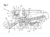
- a combine harvester 2 running agricultural machine 1 takes in its front area on a grain cutting unit 3, which is connected in a conventional manner with the inclined conveyor 4 of the combine harvester 2.
- the crop feed stream 5 passing through the inclined conveyor 4 is transferred to the threshing elements 7 of the combine harvester 2, which are at least partly covered by a so-called threshing basket 6 at the bottom, at the rear, of the inclined conveyor 4.
- a deflecting drum 8 arranged downstream of the threshing members 7 deflects the crop stream 5 emerging from the threshing members 7 in the rear region such that it is transferred directly to a separating device 10 designed as a separating rotor 9.
- the material flow 5 is conveyed so that free-moving grains 11 contained in the material flow 5 are deposited in the lower-side region of the separation rotor 9.
- the separating device 10 embodied as a separating rotor 9 in the illustrated embodiment can also be embodied as a horden shaker known per se and therefore not shown.
- Both the grains 11 deposited on concave 6 and separating rotor 9 are fed via return bottom 12 and feed bottom 13 to a cleaning device 17 consisting of a plurality of screen planes 14, 15 and a fan 16.
- the cleaned grain stream is finally transferred by elevators 18 to a grain tank 19.
- the agricultural work machine 1 has a vehicle cabin 21 in which at least one control unit 23 provided with a display unit 22 is arranged, by means of which automatically or by the operator 24 of the agricultural work machine 1 initiates a multiplicity of per se known and therefore unspecified Processes can be controlled.
- the control and regulating device 23 communicates via a so-called bus system 25 in a manner known per se with a plurality of sensor systems 26. Details regarding the structure of the sensor systems 26 are described in detail in FIGS DE 101 47 733 described, the content of which is hereby fully part of the disclosure of this patent application, so that the structure of the sensor systems 26 will not be described again in the following.
- the control and regulating device 23 is coupled to a driver assistance system 28 comprising a display unit 27.
- driver assistance system 28 may also be integrated directly into the control and regulating device 23 and the visualization of the provided by the driver assistance system 28 and explained in more detail below information 29 also directly in the control and regulating device 23 assigned Display unit 22 takes place.
- Fig. 2 2 shows a schematic representation of the display unit 22 of the control and regulation device 23 as well as the arithmetic unit 30 associated with the control and regulating device 23 and coupled to the display unit 22.
- the arithmetic unit 30 is designed such that, in addition to the internal information 31 generated by the sensor systems 26 , external information 32 and in the computing unit 30 self-stored information 33, such as expert knowledge, to process a plurality of output signals 34.
- the output signals 34 are designed to comprise at least display control signals 35 and work control signals 36, the former determining the contents of the display unit 22 and causing the change of the various working parameters 37 of the working members 20 of the agricultural machine 1, wherein arrow 37 is symbolic of the threshing drum speed stands.
- control and regulating device 23 as already described, with coupled to a driver assistance system 28, wherein the driver assistance system 28 is integrated into the agricultural machine 1 so that it can exchange data 38 in a manner to be described in more detail both with the control and regulating device 23 and with the associated display unit 22.
- FIG. 2 shown contents of the display units 22, 27 are exemplary and will be described in more detail below.
- the control unit 23 associated display unit 22 includes in its central area by the operator 24 a freely definable so-called hotkey window 38 in which important machine information, such as the level of the fuel tank 38 a, machine parameter settings 38 b and the travel speed 38 c are visualized.
- the display unit 22 comprises in its right-hand side display elements 39 for visualizing current values of certain quality parameters 40 of the agricultural machine 1.
- the display unit 39 arranged on the top visualizes the composition of the so-called “tailings” 41, wherein the left-hand representation the “tailings volume” 41 a and the right-hand representation of the "grain fraction in the tailings” 41 b visualized.
- the lower, left display element 39 visualizes the so-called “deposition losses” 42, i. those grain losses, which are discharged from the separating device 10 designed as a separating rotor 9 or Horden presentler in the rear region of the agricultural machine 1 from this and not promoted in the grain tank 19.
- the lower right display element 39 visualizes the so-called "cleaning losses" 43, in which case those grain losses are displayed, which are discharged by the cleaning device 17 in an analogous manner to the separating device 10 from the agricultural machine 1 and not conveyed into the grain tank 19.
- Each of the display elements 39 also comprises a setpoint indicator 44 in the form of a horizontal line, which defines the maximum allowable loss level of the respective quality parameter 40 previously defined by the operator 24, so that the operator 24 can quickly determine whether the agricultural work machine 1 has a sufficient quality of work.
- the setting options for the separating device 10 and the cleaning device 17 are in so-called automatic setting machines 45 deposited.
- each of the available Einstellautomaten 45 may also be wholly or partially stored in the driver assistance system 28.
- Fig. 3 describes on the basis of schematic illustrations of the control and regulating device 23 associated display unit 22 and the available Einstellautomaten 45 closer.
- Fig. 3a shows a schematic structure of the same for better understanding of the operation of the available Einstellautomaten 45.
- Both the automatic separator 46 and the automatic cleaning machine 47, as well as any setting machine 45 provided for setting working members 20 of the agricultural machine 1, are defined by characteristic fields 48.
- the evaluation variable 51 forms the previously described quality parameters 40.
- the influencing variables 50 in the exemplary embodiment illustrated include at least the rotational speed of a separating device designed as a separating rotor 9 10 and the speed of the cleaning device 17 associated with the blower 16 and the opening width of the screen planes 14, 15.
- the determined operating points 52 are taken directly into the family 48.
- the agricultural work machine 1 often works only in a small area 53 of the respectively stored characteristic field 48. So that the characteristic field 48 stored in the control and regulation device 23 reproduces the deposition or cleaning process to be modeled in the entire predefined value range at regular intervals, measurement points 54 are displayed at regular intervals approached, which are not in the currently traversed area 53 of the respective characteristic field 48 and / or in its boundary regions. This has the effect that the deposition or cleaning models deposited in the setting machines 45 also display the respective process with sufficient accuracy in the boundary region of the characteristic curves 48 and in regions of the characteristic curve field 48 that are not currently traversed.
- each quality parameter 40 here the "tailings volume” 41 a, the "grain fraction in the tailings” 41 b, the “separation loss” 42 and, the “cleaning loss” 43, is visualized qualitatively in the form of color highlighted areas 55.
- Each of the surfaces 55 changes its extent depending on the values for "separation loss” 42, "grain loss” 43 and "tailings composition” 41a, 41b determined by the control unit 23, wherein the function of the setting machines 45 is the quality criteria 40 in an optimum and below the respective setpoint indicator 44 to keep.
- FIGS Figures 3c and 3d two activation states 56, 57.
- the automatic separator 46 automatically moves to a measuring point 54 which lies either outside the region 53 which has just passed through or in the boundary region of the characteristic field 48 describing the separation of the particles on the separating device 10. So that the operator 24 of the agricultural work machine 1 is informed that the automatic separator 46 is approaching a measuring point 54 not located in the present working area 53, the surface 55 visualizing the quality parameter 40 "deposition loss" 42 is displayed fading in the display unit 22c.
- the faded surface 55 is either frozen in size or continues to visualize the change in the "deposition losses” 42.
- the latter variant keeps the operator 24 informed about the course of the change, which can also lead to the fact that the "Abscheideellae” 42 also briefly exceed the mark of the setpoint indicator 44 before reaching a steady state.
- the display element 39 visualizing the "deposition loss" 42 at least partially overlaps by a characteristic symbol 58 while the partially blended work and / or quality parameter 37, 40 is displayed passively, preferably fading.
- the structure of the display unit 22 in the further activation state 57 in accordance with Fig. 3d be adjusted.
- the automatic cleaning machine 47 automatically moves to a measuring point 54, which lies either outside the region 53 that has just passed through or in the boundary region of the characteristic field 48 describing the separation of the particles on the cleaning device 17. So that the operator 24 of the agricultural working machine 1 is informed that the cleaning machine 47 is approaching a measuring point 54 not located in the present working area 53, the quality parameters 40 "cleaning loss” 43, "tailing volume” 41 a, "grain proportion in the tailings "41 b, visualizing surfaces 55 shown fading.
- the surfaces 55 shown in a fading manner are either frozen in their size or continue to visualize the change in the "cleaning losses” 43, the "tailings volume” 41 a and the “grain portion in the tailings” 41 b.
- the latter variant keeps the operator 24 informed about the course of the changes, which can also lead to the achievement of a steady state to the fact that the "cleaning losses” 43, the "tailings volume” 41 a and the “grain fraction in the tailings” 41 b briefly the mark exceed the respective setpoint indicator 44.
- At least the display element 39 visualizing the "cleaning loss" 43 is at least partially overlapped by a characteristic symbol 58 during the partial blended working and / or quality parameters 37, 40 passive, preferably fading, is displayed.
- each of the existing setting machines 45 can be activated and deactivated independently of one another automatically or triggered by the operator 24, so that the number of simultaneously operating setting machines 45 can be selected as desired.
- all setting machines 45 are always activated to optimize the operation of the agricultural machine 1.
- a targeted shutdown of a Einstellautomaten 45 can also be effected by the fact that the operator 24 specifically a working parameter 37 by entering a defined value changes. If the override by the operator 24 takes place during the targeted approach of measuring points 54, the characteristic symbols 58 are masked out and the possibly fading representation of the working and / or quality parameters 37, 40 is canceled.
- the operator 24 in the display unit 22 receives an explicit reference to the deactivation of setting machines 45.
- control and regulating device 23 Since the control and regulating device 23 is arranged in a manner known per se such that it always visualizes the change in the quality parameters 40, irrespective of whether setting machines 45 are activated or not, it is possible to provide pictographs representing the setting machines 45 in the display unit 22 59 are positioned, which are visualized at least with highlighting activated automatic 45. The deactivation of the respective Einstellautomaten 45 is visualized accordingly by dimming of the respective icon 59.
- each setting machine 45 has its own characteristic field 48, whereby individual setting machines 45, even including a large number of characteristics fields 48, bring about an optimization of the mode of operation of the agricultural working machine 1.
- the cleaning machine 47 takes account of characteristic curves 48, which take into account both the "cleaning losses” 43 and the “tailings volume” 41 a and the "grain fraction in the tailings” 41 b.
- the characteristic curves 48 taken into account to yield useful values for the evaluation variables 51 and thus for optimum operation of the agricultural machine 1, it is provided that the starting does not occur in the present working region 53 or in the boundary regions of the characteristic curves 48 limited time intervals and limited to a certain number of measuring points 54 takes place.
- the number of selectively controllable measuring points 54 is limited to four.
- the defined time intervals within which the various measuring points 54 are repeatedly controlled are such that the duration of the time interval increases with increasing use time of the agricultural working machine 1 and is preferably less than 15 minutes at the beginning of the operating time and increases to 30 minutes with increasing operating time elevated.
- the control and regulating device 23 and thus the setting machines 45 are automatically activated with startup of the agricultural machine 1.
- an indication of an increase in efficiency can be generated by activating the respective setting machine 45 to the operator 24.
- FIG. 4 shows a detailed view of the driver assistance system 28.
- the available process control strategies 61 are first visualized.
- four process control strategies 61 can be selected, namely "balanced” 61 a; "maximum throughput”61b;"minimum fuel consumption” 61 c and "high threshing quality” 61 d.
- the driver assistance system 28 regulates the mode of operation of the agricultural machine 1 such that the maximum possible throughput, in which just the predefined setpoint values for a permissible grain loss, consisting of separation loss 42 and cleaning loss 43, are complied with become. If the "minimum fuel input" process management strategy 61c is selected, the driver assistance system 28 regulates the mode of operation of the agricultural work machine 1 such that the drive energy requirement decreases. This is preferably achieved by reducing the rotational speed of one or more working members 20.
- driver assistance system 28 operates in the "high threshing quality" process management strategy 61b, in addition to low grain losses, a small grain breakage and a low admixture fraction in the harvested grain are aimed for.
- the control strategy "balanced" 61 a takes into account for all optimizable working and / or quality parameters 37, 40 medium levels, so that the overall result is a balanced operation of the agricultural machine 1, without giving priority to certain work and quality parameters 37, 40.
- each of the process management strategies 61 can be selected either via the touchscreen function if the display 60 is designed as a touch screen monitor or can be activated via a key 63 assigned to the respective process control strategy 61. It is within the scope of the invention that the activation of the respective process control strategy 61 by means of a rotary-push switch 64th is feasible.
- a viewing window 65 is positioned, which includes natural language comments and in FIG. 4 gives an indication of the currently activated process management strategy 61.
- the driver assistance system 28 is coupled to the control and regulating device 23 associated with the agricultural work machine 1, wherein it is also conceivable that the driver assistance system 28 and the control and regulation device 23 are combined in a single structural unit in a manner not shown.
- the various work and quality parameters 37, 40 are optimized in the manner already described on the basis of the characteristic curves 48 defined by characteristic curves 49. If the arithmetic unit 30 assigned to the open-loop and closed-loop control unit determines that defined limit values for one or more of the quality parameters 40 are not maintainable or even lower than predefined values, the driver assistance system proposes according to the invention a change of the process control strategy 61.
- FIG. 5 shows various scenarios for a proposal to change the litigation strategy 61.
- FIG. 5a suggests the driver assistance system 28 in the display window 65 associated with its display 60 in natural language form, to change from the process control strategy "balanced" 61 a in the process strategy "high threshing quality” 61 d to effect an improvement in grain cleanliness.
- FIG. 5b 10 illustrates how the driver assistance system 28 proposes a change from the "high threshing quality" process control strategy 61 d into the "maximum throughput" process control strategy 61 b in a natural-language manner in order to effect a reduction of the grain quantity in the so-called tailing.
- This dialog is in turn visualized in the display 60 associated with the viewing window 65.
- FIG. 5a suggests the driver assistance system 28 in the display window 65 associated with its display 60 in natural language form, to change from the process control strategy "balanced" 61 a in the process strategy "high threshing quality” 61 d to effect an improvement in grain cleanliness.
- the driver assistance system 28 proposes a change of the process management strategy 61 if the predefined setpoint values of one or more quality parameters 40 within the selected process management strategy 61 do not exist can be reached or if the driver assistance system 28 recognizes that even more favorable values for one or more of the quality parameters 40 can be achieved when a different process management strategy 61 is selected.
- the operator 24 of the agricultural work machine 1 wants to accept the change of the process management strategy 61 proposed by the driver assistance system 28, he confirms this by activating an "apply" field 66.
- the optimization process activated thereby is based on an interaction of the operator 24 with the driver assistance system 28.
- the optimization process be the operator 24 in the display unit 22 of the control and regulating device 23 according to the explanations to the Figures 2 and 3 the changes in the working parameters 37 caused by the driver assistance system 28 and their effect on the respective quality parameters 40 are displayed.
- the driver assistance system 28 is designed such that the operator 24 has to evaluate the optimization results. Depending on the evaluation by the operator, the optimization process is continued or terminated.
- the operator 24 is made aware of the effects on the mode of operation resulting from a process-management strategy change by superimposing supplementary natural-language comments, for example on the influence on specific quality parameters 40, in the respective viewing window 65.
- a description of the proposed process management strategy 61 can be manually retrieved and displayed or displayed automatically in order to give the operator 24 the opportunity to compare the currently selected with the proposed process management strategy 61.
- Another aspect of evaluating the interaction of the operator 24 with the driver assistance system 28 is the registration of a repeated interaction concerning the same optimization goal. This determination is used to more strongly weight this optimization target within the optimization process, so that a repeated interaction of the operator 24 with the driver assistance system 28 to optimize the same work and / or quality parameter 37, 40 causes the driver assistance system 28 to propose a change of the process control strategy 61.
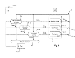
- FIG. 6 The structure of a control and regulating device 68 embodying the process coordinator 67 according to the invention is shown on the basis of a signal flow diagram. It lies within the scope of the invention that the control and regulating device 68 comprising the process coordinator 67 is either from the already described control and regulating device 23 or the driver assistance system 28 is formed.
- the control and regulating device 68 comprises the already described automatic setting machines 45 automatic separator 46 and automatic cleaning machine 47.
- the adjusting machine 45 and the process coordinator 66 receiving control circuit 69 comprises a driving speed of the agricultural machine 1 defining driving speed controller 70. According to the description of the FIGS.
- the agricultural machine 1 has a plurality of sensor systems 26, the various working and quality parameters 37, 40, the travel speed 38c and harvesting crop characteristics. Depending on the driving speed, the sensor systems 26 generate an actual signal Qact of the crop stream passing through the agricultural working machine. Further, the sensor systems 26 assigned to the separating device 10 and the cleaning device 17 generate the separation loss signals IA defining the separation loss 42 and the cleaning loss signals IR defining the cleaning loss 43 ,
- the actual signal Qact of the Ernetgut besatzes is passed within the control loop 69 to the vehicle speed controller 70 as an input signal.
- the deposition loss signals IA are transmitted to the automatic separator 46 and the cleaning loss signals IR to the automatic cleaning machine 47 as their input signals.
- good throughput signals Qmax1, Qmax2, Qmax3 are finally generated from these input signals, which are dependent on the driving speed, dependent on the cleaning loss and depending on the deposition loss, respectively defining the maximum processable throughput of the crop stream 5.
- These good throughput signals Qmax1-3 are then transferred to the process coordinator 67 according to the invention.
- the process coordinator determines from the good throughput signals Qmax1-3 given to it an optimum material throughput and transfers a corresponding optimum material throughput signal Qopt to the cruise control 70 and the automatic adjusting machines 45.
- the optimized good throughput signal Qopt will correspond to the determined lowest value of the maximum material throughputs Qmax1-3.
- the vehicle speed controller 70 finally generates an optimized vehicle speed signal V opt from this, so that the agricultural machine 1 is moved at this optimized vehicle speed.
- the setting machines 45 generate optimized values for a variety of working parameters 37opt of the agricultural machine 1 matched to this optimized material throughput signal Qopt.
- the control loop 69 is run through again in the described manner, so that finally results in a continuously running control process.
- the process coordinator 67 determines, for at least one common parameter 71 of the respective working members 20, a value at which at least the working members 20 monitored by the control and regulating unit 68 operate optimally and this determined value of the at least one common parameter 71 serves as a reference variable 72 is used for the control and regulating device 68.
- the common parameter 71 is not limited to the described optimized Erntegutduchsatz Qopt but can also be related directly to the respective layer height, so then in a similar manner a driving speed-dependent actual layer height and Fahr Anthonysregler- and Einstellautomaten-dependent maximum layer heights result from which then in the process coordinator 67 an optimized layer height is determined. In an analogous manner, the determined optimized layer height will correspond to the lowest values of the determined maximum layer heights.
Abstract
Description
Die vorliegende Erfindung betrifft eine selbstfahrende landwirtschaftliche Arbeitsmaschine mit Arbeitsorganen, deren Arbeitsparameter durch zumindest eine Steuer- und Regeleinrichtung automatisiert einstellbar sind gemäß dem Oberbegriff des Anspruches 1.The present invention relates to a self-propelled agricultural machine with work organs whose working parameters are automatically adjustable by at least one control and regulating device according to the preamble of
Aus dem Stand der Technik ist es bekannt Arbeits- und Qualitätsparameter einer landwirtschaftlichen Arbeitsmaschine mittels einer Steuer- und Regeleinrichtung zu überwachen und zu optimieren. Die
Diese bekannten Optimierungsmethoden gelangen dann an ihre Grenzen, wenn die an die Bedingungen der jeweiligen Arbeitsorgane angepassten Regelungsalgorithmen unterschiedliche Gutdurchsatzwerte für ein optimales Arbeiten des jeweiligen Arbeitsorgans ermitteln. Daher war bei derartigen Regelungen bisher vorgesehen, dass die Fahrgeschwindigkeit der landwirtschaftlichen Arbeitsmaschine vorgegeben wurde und die Optimierung der Arbeitsweise der Arbeitsorgane innerhalb dieser Fahrgeschwindigkeitsgrenzen vorgenommen wird. Dies konnte bisher zu dem Nachteil führen, dass die landwirtschaftliche Arbeitsmaschine insgesamt nicht in ihrem optimalsten Arbeitspunkt betrieben wird.These known optimization methods then reach their limits when the control algorithms adapted to the conditions of the respective working organs determine different material throughput values for optimum working of the respective working organ. Therefore, it was previously provided in such regulations that the driving speed of the agricultural machine was specified and the optimization of the operation of the working bodies within these driving speed limits is made. This has so far led to the disadvantage that the agricultural machine as a whole is not operated at its most optimal operating point.
Aufgabe der vorliegenden Erfindung ist es daher, die Steuer- und Regeleinrichtung einer landwirtschaftlichen Arbeitsmaschine derart weiterzuentwickeln, dass eine qualitativ hochwertige Regelung der landwirtschaftlichen Arbeitsmaschine möglich wird.Object of the present invention is therefore to further develop the control and regulating device of an agricultural machine such that a high-quality control of the agricultural machine is possible.
Diese Aufgabe wird erfindungsgemäß durch die kennzeichnenden Merkmale des unabhängigen Anspruches 1 gelöst.This object is achieved by the characterizing features of
Indem die Steuer- und Regeleinrichtung einer selbstfahrenden landwirtschaftlichen Arbeitsmaschine ein Prozesskoordinator umfasst, der zumindest einen gemeinsamen Parameter der jeweiligen Arbeitsorgane auswertet, und zumindest für diesen Parameter einen Wert ermittelt, bei dem zumindest die durch die Steuer- und Regeleinrichtung überwachten Arbeitsorgane optimal arbeiten und dieser ermittelte Wert des zumindest einen gemeinsamen Parameters als Führungsgröße der Steuer- und Regelungseinrichtung verwendet wird ist sichergestellt, dass die landwirtschaftliche Arbeitsmaschine insgesamt in ihrem optimalsten Betriebspunkt betrieben werden kann.By the control and regulating device of a self-propelled agricultural work machine includes a process coordinator, which evaluates at least one common parameter of the respective work organs, and at least for this parameter determines a value at which at least the monitored by the control and regulating devices working optimally and this determined Value of the at least one common parameter is used as a reference variable of the control and regulating device ensures that the agricultural machine can be operated in total in its most optimal operating point.
Eine besonders effiziente Betriebspunktoptimierung der landwirtschaftlichen Arbeitsmaschine ergibt sich dann, wenn als Parameter der maximal verarbeitbare Gutdurchsatz und/oder die maximal verarbeitbare Schichthöhe der jeweiligen Arbeitsorgane ausgewertet wird.A particularly efficient operating point optimization of the agricultural working machine results when the maximum workable throughput and / or the maximum workable layer height of the respective working organs is evaluated as a parameter.
Ein besonders effizient arbeitender Regelkreis ergibt sich in einer vorteilhaften Ausgestaltung der Erfindung dann, wenn der Prozesskoordinator aus dem für das jeweilige Arbeitsorgan ermittelten maximal verarbeitbaren Gutdurchsatz oder die maximal verarbeitbare Schichthöhe den optimierten Wert ermittelt und diesen als Führungsgröße für die Steuer- und Regeleinrichtung definiert.A particularly efficiently operating control loop results in an advantageous embodiment of the invention when the process coordinator determines the optimized value from the maximum workable throughput determined for the respective working element or the maximum workable layer height and defines this as the reference variable for the control and regulating device.
Damit sichergestellt ist, dass kein Arbeitsorgan der landwirtschaftlichen Arbeitsmaschine in einem suboptimalen Bereich arbeitet, ist in einer weiteren vorteilhaften Ausgestaltung vorgesehen, dass der optimierte Wert dem niedrigsten der ermittelten maximalen Gutdurchsätze oder Schichthöhen entspricht.To ensure that no working body of the agricultural machine works in a sub-optimal range, is in a further advantageous embodiment provided that the optimized value corresponds to the lowest of the determined maximum throughputs or layer heights.
Die Qualität des Optimierungsergebnisses lässt sich dadurch noch steigern, wenn die Steuer- und Regeleinrichtung neben Arbeitsparametern auch Qualitätsparameter der landwirtschaftlichen Arbeitsmaschine überwacht und regelt und wobei die Regelung der Arbeits- und Qualitätsparameter eines oder mehrerer Arbeitsorgane in Einstellautomaten hinterlegt ist. Ein besonders wirksamer Einfluss auf eine effiziente Arbeitsweise der landwirtschaftlichen Arbeitsmaschine wird in diesem Zusammenhang dann erreicht, wenn die Einstellautomaten zumindest einen Reinigungsautomat und einen Abscheideautomat umfassen.The quality of the optimization result can be further increased if the control and regulating device in addition to working parameters and quality parameters of the agricultural machine monitors and regulates and wherein the regulation of the work and quality parameters of one or more working bodies is stored in automatic teller. A particularly effective influence on an efficient operation of the agricultural machine is achieved in this context, when the setting machines include at least a cleaning machine and an automatic separator.
Indem die von dem Prozesskoordinator ermittelte Führungsgröße der Steuer- und Regeleinrichtung an einen die Fahrgeschwindigkeit vorgebenden Fahrgeschwindigkeitsregler übergeben wird und aus den in dem Fahrgeschwindigkeitsregler hinterlegten Kennlinien eine Fahrgeschwindigkeit der landwirtschaftlichen Arbeitsmaschine bestimmt wird, wird auf einfache Weise sichergestellt, dass keines der Arbeitsorgane überlastet wird.By passing the command variable of the control and regulating device determined by the process coordinator to a driving speed controller which predefines the driving speed and determining a driving speed of the agricultural machine from the characteristic curves stored in the driving speed controller, it is ensured in a simple manner that none of the working members is overloaded.
Ein besonders effizient arbeitender Regelkreis ergibt sich dann, wenn in einer vorteilhaften Ausgestaltung der Erfindung die Arbeits- und/oder Qualitätsparameter der landwirtschaftlichen Arbeitsmaschine in einem kontinuierlich arbeitenden Regelkreis mittels der Einstellautomaten überwacht und geregelt werden und das der Prozesskoordinator in demselben Regelkreis kontinuierlich einen optimierten Wert des Gutdurchsatzes und/oder der Schichthöhe als Führungsgröße der Regelung an den Fahrgeschwindigkeitsregler und die Einstellautomaten übergibt und diese ebenfalls kontinuierlich in Abhängigkeit von dieser Führungsgröße ein Fahrgeschwindigkeitssignal zur Anpassung der Fahrgeschwindigkeit der landwirtschaftlichen Arbeitsmaschine und optimierte Werte der Arbeitsparameter generieren.A particularly efficiently operating control loop results when, in an advantageous embodiment of the invention, the working and / or quality parameters of the agricultural machine are monitored and controlled in a continuously operating control loop by means of the setting machines and the process coordinator in the same control loop continuously an optimized value of Good throughput and / or the layer height as a reference variable of the control to the cruise control and the Einstellautomaten passes and they also generate continuously in response to this command variable a vehicle speed signal for adjusting the driving speed of the agricultural machine and optimized values of the working parameters.
Weitere vorteilhafte Ausgestaltungen der Erfindungen sind den Unteransprüchen zu entnehmen und werden nachfolgend anhand von in Zeichnungen dargestellten Ausführungsbeispielen näher erläutert.Further advantageous embodiments of the invention are set out in the dependent claims and are explained in more detail with reference to exemplary embodiments illustrated in the drawings.
Es zeigen:
- Fig. 1
- eine schematische Darstellung einer als Mähdrescher ausgeführten landwirtschaftlichen Arbeitsmaschine;
- Fig. 2
- eine schematische Darstellung einer Anzeigestruktur einer Steuer- und Regelungseinrichtung;
- Fig. 3a - 3d
- schematische Darstellungen der Anzeigestruktur der Steuer- und Regelungseinrichtung in unterschiedlichen Betriebssituationen;
Figur 4- eine schematische Darstellung des Fahrerassistenzsystems;
Figur 5- verschiedene Betriebszustände des Fahrerassistenzsystems.
- Figur 6
- eine schematische Darstellung des erfindungsgemäßen Regelkreises
- Fig. 1
- a schematic representation of a running as a combine agricultural machine;
- Fig. 2
- a schematic representation of a display structure of a control and regulating device;
- Fig. 3a - 3d
- schematic representations of the display structure of the control and regulating device in different operating situations;
- FIG. 4
- a schematic representation of the driver assistance system;
- FIG. 5
- various operating states of the driver assistance system.
- FIG. 6
- a schematic representation of the control loop according to the invention
Die in
Weiter verfügt die landwirtschaftliche Arbeitsmaschine 1 über eine Fahrzeugkabine 21 in der zumindest eine mit einer Anzeigeeinheit 22 versehene Steuer- und Regeleinrichtung 23 angeordnet ist, mittels derer automatisch oder vom Bediener 24 der landwirtschaftlichen Arbeitsmaschine 1 initiiert eine Vielzahl von an sich bekannten und daher nicht näher erläuterten Prozessen gesteuert werden können. Die Steuer- und Regeleinrichtung 23 kommuniziert über ein sogenanntes Bussystem 25 in an sich bekannter Weise mit einer Vielzahl von Sensorsystemen 26. Einzelheiten bezüglich der Struktur der Sensorsysteme 26 sind detailliert in der
Die Anzeigeeinheit 22 umfasst in ihrem rechtsseitigen Bereich Anzeigeelemente 39 zur Visualisierung aktueller Werte bestimmter Qualitätsparameter 40 der landwirtschaftlichen Arbeitsmaschine 1. Im dargestellten Ausführungsbeispiel visualisiert das obenseitig angeordnete Anzeigeelement 39 die Zusammensetzung der sogenannten "Überkehr" 41, wobei die linkseitige Darstellung das "Überkehrvolumen" 41 a und die rechtsseitige Darstellung den "Kornanteil in der Überkehr" 41 b visualisiert. Das untere, linke Anzeigeelement 39 visualisiert die sogenannten "Abscheideverluste" 42, d.h. diejenigen Kornverluste, die von der als Trennrotor 9 oder Hordenschüttler ausgeführten Trenneinrichtung 10 im rückwärtigen Bereich der landwirtschaftlichen Arbeitsmaschine 1 aus dieser ausgetragen und nicht in den Korntank 19 gefördert werden. Das untere, rechte Anzeigeelement 39 visualisiert die sogenannten "Reinigungsverluste" 43, wobei hier diejenigen Kornverluste angezeigt werden, die von der Reinigungseinrichtung 17 in analoger Weise zur Trenneinrichtung 10 aus der landwirtschaftlichen Arbeitsmaschine 1 ausgetragen und nicht in den Korntank 19 gefördert werden. Jedes der Anzeigeelemente 39 umfasst zudem einen als waagerechten Strich ausgeführten Sollwertanzeiger 44, der das maximal zulässige und vom Bediener 24 zuvor definierte Verlustniveau des jeweiligen Qualitätsparameters 40 definiert, sodass der Bediener 24 schnell erfassen kann, ob die landwirtschaftliche Arbeitsmaschine 1 eine hinreichende Arbeitsqualität aufweist.The
Aufgrund der komplexen Zusammenhänge zwischen verschiedensten Maschinenparametern 38a-c und zumindest den Qualitätsparametern 40 sind die Einstelloptionen für die Trenneinrichtung 10 und die Reinigungseinrichtung 17 in sogenannten Einstellautomaten 45 hinterlegt. Im dargestellten Ausführungsbeispiel sind gemäß
Wird die landwirtschaftliche Arbeitsmaschine 1, im hier dargestellten Ausführungsbeispiel der Mähdrescher 2, mit aktiviertem Abscheideautomat 46 und aktiviertem Reinigungsautomat 47 betrieben, hat die der Steuer- und Regeleinrichtung 23 zugeordnete Anzeigeeinheit 22 die in
Muss nun ein definierter Messpunkt 54 durch die Einstellautomaten 45 angefahren werden, ergeben sich für das hier beschriebene Ausführungsbeispiel gemäß den
In analoger Weise kann die Struktur der Anzeigeeinheit 22 in dem weiteren Aktivierungszustand 57 gemäß
In an sich bekannter Weise kann jeder der vorhandenen Einstellautomaten 45 voneinander unabhängig automatisch oder vom Bediener 24 ausgelöst aktiviert und deaktiviert werden, sodass die Anzahl der gleichzeitig arbeitenden Einstellautomaten 45 beliebig wählbar ist. Vorzugsweise sind stets alle Einstellautomaten 45 zur Optimierung der Arbeitsweise der landwirtschaftlichen Arbeitsmaschine 1 aktiviert. Es liegt im Rahmen der Erfindung, dass eine gezielte Abschaltung eines Einstellautomaten 45 auch dadurch bewirkt werden kann, dass der Bediener 24 gezielt einen Arbeitsparameter 37 durch Eingabe eines definierten Wertes ändert. Findet die Übersteuerung durch den Bediener 24 während des gezielten Anfahrens von Messpunkten 54 statt, werden die charakteristischen Symbole 58 ausgeblendet und die gegebenenfalls verblassende Darstellung der Arbeits- und/oder Qualitätsparameter 37, 40 aufgehoben. In diesem Zusammenhang kann zudem vorgesehen sein, das der Bediener 24 in der Anzeigeeinheit 22 einen expliziten Hinweis auf die Deaktivierung von Einstellautomaten 45 erhält.In a manner known per se, each of the existing
Da die Steuer- und Regeleinrichtung 23 in an sich bekannter Weise so beschaffen ist, dass sie stets die Änderung der Qualitätsparameter 40 visualisiert, unabhängig davon, ob Einstellautomaten 45 aktiviert sind oder nicht kann vorgesehen sein, dass in der Anzeigeeinheit 22 die Einstellautomaten 45 repräsentierende Piktogramme 59 positioniert sind, die bei aktivem Einstellautomat 45 zumindest farblich hervorgehoben visualisiert werden. Die Deaktivierung des jeweiligen Einstellautomaten 45 wird entsprechend durch Abblendung des jeweiligen Piktogramms 59 visualisiert.Since the control and regulating
Weiterkann vorgesehen sein, dass jeder Einstellautomat 45 über sein eigenes Kennlinienfeld 48 verfügt, wobei einzelne Einstellautomaten 45, auch unter Einbeziehung einer Vielzahl von Kennlinienfeldern 48 eine Optimierung der Arbeitsweise der landwirtschaftlichen Arbeitsmaschine 1 bewirken. Im dargestellten Ausführungsbeispiel berücksichtigt der Reinigungsautomat 47 Kennlinienfelder 48, die sowohl die "Reinigunsgverluste" 43 als auch das "Überkehrvolumen" 41 a und den "Kornanteil in der Überkehr" 41 b berücksichtigen. Damit die berücksichtigten Kennlinienfelder 48 auch bei schwankenden Einflussgrößen 50 brauchbare Werte für die Bewertungsgrößen 51 und damit für eine optimale Arbeitsweise der landwirtschaftlichen Arbeitsmaschine 1 liefern, ist vorgesehen, dass das Anfahren nicht im gegenwärtigen Arbeitsbereich 53 oder in den Grenzbereichen der Kennlinienfelder 48 liegender Messpunkte 54 in definierten zeitlichen Abständen und auf eine bestimmte Anzahl von Messpunkten 54 beschränkt erfolgt. Vorzugsweise ist die Anzahl der gezielt ansteuerbaren Messpunkte 54 auf vier beschränkt. Die definierten Zeitintervalle, innerhalb derer die verschiedenen Messpunkte 54 wiederholt angesteuert werden, sind so beschaffen, dass die Dauer des Zeitintervalls mit zunehmender Einsatzzeit der landwirtschaftlichen Arbeitsmaschine 1 zunimmt und vorzugsweise zu Beginn der Einsatzzeit kleiner als 15 Minuten ist und sich mit zunehmender Einsatzzeit auf 30 Minuten erhöht. Zudem kann vorgesehen sein, dass die Steuer- und Regeleinrichtung 23 und damit auch die Einstellautomaten 45 automatisch mit Inbetriebnahme der landwirtschaftlichen Arbeitsmaschine 1 aktiviert werden. In diesem Zusammenhang kann zudem vorgesehen sein, dass bei inaktiven Einstellautomaten 45 ein Hinweis auf eine Effizienzsteigerung durch Aktivierung des jeweiligen Einstellautomaten 45 an den Bediener 24 generierbar ist.It can also be provided that each setting
Wird die Prozessführungsstrategie "maximaler Durchsatz" 61 b gewählt, regelt das Fahrerassistenzsystem 28 die Arbeitsweise der landwirtschaftlichen Arbeitsmaschine 1 so, dass der maximal mögliche Durchsatz, bei dem gerade noch die vordefinierten Sollwerte für einen zulässigen Kornverlust, bestehend aus Abscheideverlust 42 und Reinigungsverlust 43, eingehalten werden. Wird die Prozessführungsstrategie "minimaler Kraftstoffeinsatz" 61c gewählt, regelt das Fahrerassistenzsystem 28 die Arbeitsweise der landwirtschaftlichen Arbeitsmaschine 1 so, dass der Antriebsenergiebedarf sinkt. Vorzugsweise wird dies dadurch erreicht, dass die Drehzahl eines oder mehrere Arbeitsorgane 20 reduziert wird. Arbeitet das Fahrerassistenzsystem 28 in der Prozessführungsstrategie "hohe Druschqualität" 61 b wird neben niedrigen Kornverlusten ein geringer Körnerbruch und ein niedriger Beimengungsanteil im geernteten Korn angestrebt. Die Regelstrategie "ausgeglichen" 61 a berücksichtig für alle optimierbaren Arbeits- und/oder Qualitätsparameter 37, 40 mittlere Niveaus, sodass sich insgesamt eine ausgewogene Arbeitsweise der landwirtschaftlichen Arbeitsmaschine 1 ergibt, ohne dass bestimmten Arbeits- und Qualitätsparametern 37, 40 eine Priorität zukommt.If the process control strategy "maximum throughput" 61 b is selected, the
Jede der Prozessführungsstrategien 61 ist je nach Beschaffenheit des das Fahrerassistenzsystem 28 und das Display 60 aufnehmenden Gehäuses 62 entweder via Touchscreen-Funktion auswählbar, wenn das Display 60 als Touchscreen-Monitor ausgebildet ist, oder über eine der jeweiligen Prozessführungsstrategie 61 zugeordnete Taste 63 aktivierbar. Es liegt im Rahmen der Erfindung, dass die Aktivierung der jeweiligen Prozessführungsstrategie 61 auch mittels eines Dreh-Drück-Schalters 64 bewirkbar ist. Im oberen Bereich des Displays 60 ist zudem ein Sichtfenster 65 positioniert, welches natürlichsprachige Kommentare umfasst und in
Gemäß den vorherigen Ausführungen ist das Fahrerassistenzsystem 28 mit der der landwirtschaftlichen Arbeitsmaschine 1 zugeordneten Steuer- und Regeleinrichtung 23 gekoppelt, wobei es auch denkbar ist, dass das Fahrerassistenzsystem 28 und die Steuer- und Regeleinrichtung 23 in nicht dargestellter Weise in einer einzigen Baueinheit zusammengefasst sind. Nachdem eine erste Prozessführungsstrategie 61 durch den Bediener 24 ausgewählt wurde werden die verschiedenen Arbeits- und Qualitätsparameter 37, 40 in der bereits beschriebenen Weise anhand der hinterlegten von Kennlinien 49 definierten Kennlinienfelder 48 optimiert. Ermittelt die der Steuer- und Regeleinrichtung 23 zugeordnete Recheneinheit 30, dass innerhalb einer gewählten Prozessführungsstrategie 61 definierte Grenzwerte für einen oder mehrere der Qualitätsparameter 40 nicht einhaltbar sind oder noch niedriger als vorgegeben sein könnten, schlägt das Fahrerassistenzsystem 28 erfindungsgemäß einen Wechsel der Prozessführungsstrategie 61 vor.According to the previous explanations, the
Will der Bediener 24 der landwirtschaftlichen Arbeitsmaschine 1 den vom Fahrerassistenzsystem 28 vorgeschlagenen Wechsel der Prozessführungsstrategie 61 akzeptieren bestätigt er dies durch Aktivierung eines "Übernehmen"-Feldes 66. Der dadurch aktivierte Optimierungsprozess basiert auf einer Interaktion des Bedieners 24 mit dem Fahrerassistenzsystem 28. Während des Optimierungsprozesses werden dem Bediener 24 in der Anzeigeeinheit 22 der Steuer- und Regeleinrichtung 23 gemäß den Erläuterungen zu den
Ein weiterer Aspekt der Auswertung der Interaktion des Bedieners 24 mit dem Fahrerassistenzsystem 28 ist das Registrieren einer wiederholten Interaktion, die das selbe Optimierungsziel betrifft. Diese Feststellung wird herangezogen, um innerhalb des Optimierungsprozesses dieses Optimierungsziel stärker zu gewichten, sodass eine wiederholte Interaktion des Bedieners 24 mit dem Fahrerassistenzsystem 28 zur Optimierung desselben Arbeits- und/oder Qualitätsparameters 37, 40 das Fahrerassistenzsystem 28 veranlasst, einen Wechsel der Prozessführungsstrategie 61 vorzuschlagen.Another aspect of evaluating the interaction of the
Das Ist-Signals Qist des Ernetgutdurchsatzes wird innerhalb des Regelkreises 69 an den Fahrgeschwindigkeitsregler 70 als Eingangssignal übergeben. In analoger Weise werden die Abscheideverlustsignale IA an den Abscheideautomat 46 und die Reinigungsverlustsignale IR an den Reingungsautomat 47 als deren Eingangssignale übergeben. Im Fahrgeschwindigkeitsregler 70 und den Einstellautomaten 45 werden aus diesen Eingangssignalen schließlich Gutdurchsatzsignale Qmax1, Qmax2, Qmax3 generiert, die fahrgeschwindigkeitsabhängig, reinigungsverlustabhängig und abscheideverlustabhängig jeweils den maximal verarbeitbaren Gutdurchsatz des Erntegutstromes 5 definieren. Diese Gutdurchsatzsignale Qmax1-3 werden sodann an den erfindungsgemäßen Prozesskoordinator 67 übergeben. Der Prozesskoordinator bestimmt aus den an ihn übergebenen Gutdurchsatzsignalen Qmax1-3 einen optimalen Gutdurchsatz und übergibt ein damit korrespondierendes optimales Gutdurchsatzsignal Qopt an den Fahrgeschwindigkeitsregler 70 und die Einstellautomaten 45. In der Regel wird das optimierte Gutdurchsatzsignal Qopt dem ermittelten niedrigsten Wert der maximalen Gutdurchsätze Qmax1-3 entsprechen.The actual signal Qact of the Ernetgutdurchsatzes is passed within the
Der Fahrgeschwindigkeitsregler 70 generiert hieraus schließlich ein optimiertes Fahrgeschwindigkeitssignal Vopt, sodass die landwirtschaftliche Arbeitsmaschine 1 mit dieser optimierten Fahrgeschwindigkeit bewegt wird. Zugleich generieren die Einstellautomaten 45 auf dieses optimierte Gutdurchsatzsignal Qopt abgestimmte optimierte Werte für verschiedenste Arbeitsparameter 37opt der landwirtschaftlichen Arbeitsmaschine 1. Nachdem die Fahrgeschwindigkeit der landwirtschaftlichen Arbeitsmaschine 1 angepasst und die optimierten Arbeitsparameter 37opt eingestellt sind wird der Regelkreis 69 in der beschriebenen Weise erneut durchlaufen, sodass sich schließlich ein kontinuierlich ablaufender Steuer- und Regelprozess ergibt.The
Auf diese Weise ermittelt der erfindungsgemäße Prozesskoordinator 67 zumindest für einen gemeinsamen Parameter 71 der jeweiligen Arbeitsorgane 20 einen Wert, bei dem zumindest die durch die Steuer- und Regeleinrichtung 68 überwachten Arbeitsorgane 20 optimal arbeiten und wobei dieser ermittelte Wert des zumindest einen gemeinsamen Parameters 71 als Führungsgröße 72 für die Steuer- und Regelungseinrichtung 68 verwendet wird. Ist liegt im Rahmen der Erfindung, dass der gemeinsame Parameter 71 nicht auf den beschriebenen optimierten Erntegutduchsatz Qopt beschränkt ist sondern auch unmittelbar auf die jeweilige Schichthöhe bezogen sein kann, sodass sich dann in analoger Weise eine fahrgeschwindigkeitsabhängige Ist-Schichthöhe sowie Fahrgeschwindigkeitsregler- und Einstellautomaten-abhängig maximale Schichthöhen ergeben aus denen dann im Prozesskoordinator 67 eine optimierte Schichthöhe ermittelt wird. In analoger Weise wird die ermittelte optimierte Schichthöhe dem niedrigsten Werte der ermittelten maximalen Schichthöhen entsprechen.In this way, the
Claims (9)
dadurch gekennzeichnet, dass
ein Prozesskoordinator (67) zumindest einen gemeinsamen Parameter (71) der jeweiligen Arbeitsorgane (20) auswertet, und zumindest für diesen Parameter (71) einen Wert ermittelt, bei dem zumindest die durch die Steuer- und Regeleinrichtung (68) überwachten Arbeitsorgane (20) optimal arbeiten und wobei dieser ermittelte Wert des zumindest einen gemeinsamen Parameters (71) als Führungsgröße (72) der Steuer- und Regelungseinrichtung (68) verwendet wird.Self-propelled agricultural machine with work organs whose working parameters are automatically adjustable by at least one control and regulating device, wherein the agricultural machine is moved at a driving speed, which is controlled automatically depending on at least one Erntegutparameter and / or a working parameter of the agricultural machine by a cruise control .
characterized in that
a process coordinator (67) evaluates at least one common parameter (71) of the respective working members (20), and determines a value for at least this parameter (71) in which at least the working members (20) monitored by the control and regulating unit (68) operate optimally and wherein this determined value of the at least one common parameter (71) as a reference variable (72) of the control and regulating device (68) is used.
dadurch gekennzeichnet, dass
als Parameter (71) der maximal verarbeitbare Gutdurchsatz (Qmax1-3) und/oder die maximal verarbeitbare Schichthöhe der jeweiligen Arbeitsorgane (20) ausgewertet wird.Self-propelled agricultural work machine according to claim 1,
characterized in that
the maximum workable throughput (Qmax1-3) and / or the maximum workable layer height of the respective working elements (20) is evaluated as parameter (71).
dadurch gekennzeichnet, dass
der Prozesskoordinator (67) aus dem für das jeweilige Arbeitsorgan (20) ermittelten maximal verarbeitbaren Gutdurchsatz (Qmax1-3) oder die maximal verarbeitbare Schichthöhe den optimierten Wert (Qopt) ermittelt und diesen als Führungsgröße (72) für die Steuer- und Regeleinrichtung (68) definiert.Self-propelled agricultural work machine according to claim 2,
characterized in that
the process coordinator (67) determines the optimized value (Qopt) from the maximum processable throughput (Qmax1-3) determined for the respective working element (20) or the maximum processible layer height and uses this as the reference variable (72) for the control and regulating device (68 ) Are defined.
dadurch gekennzeichnet, dass
der optimierte Wert dem niedrigsten der ermittelten maximalen Gutdurchsätze (Qmax1-3) oder Schichthöhen entspricht.Self-propelled agricultural work machine according to claim 3,
characterized in that
the optimized value is the lowest of the determined maximum throughputs (Qmax1-3) or layer heights.
dadurch gekennzeichnet, dass
die Steuer- und Regeleinrichtung (68) neben Arbeitsparametern (37) auch Qualitätsparameter (40) der landwirtschaftlichen Arbeitsmaschine (1) überwacht und regelt und wobei die Regelung der Arbeits- und Qualitätsparameter (37, 40) eines oder mehrerer Arbeitsorgane (20) in Einstellautomaten (45) hinterlegt ist.Self-propelled agricultural work machine according to one of the preceding claims,
characterized in that
the control and regulating device (68) in addition to working parameters (37) and quality parameters (40) of the agricultural machine (1) monitors and controls and wherein the control of the working and quality parameters (37, 40) of one or more working organs (20) in Einstellautomaten (45) is deposited.
dadurch gekennzeichnet, dass
die Einstellautomaten (45) zumindest einen Reinigungsautomat (47) und einen Abscheideautomat (46) umfassen.Self-propelled agricultural work machine according to claim 5,
characterized in that
the setting machines (45) comprise at least one cleaning machine (47) and an automatic separator (46).
dadurch gekennzeichnet, dass
die vom dem Prozesskoordinator (67) ermittelte Führungsgröße (72) der Steuerund Regeleinrichtung (68) an einen die Fahrgeschwindigkeit vorgebenden Fahrgeschwindigkeitsregler (70) übergeben wird und aus den in dem Fahrgeschwindigkeitsregler (70) hinterlegten Kennlinien eine Fahrgeschwindigkeit der landwirtschaftlichen Arbeitsmaschine (1) bestimmt wird.Self-propelled agricultural work machine according to one of the preceding claims,
characterized in that
the control variable (72) of the control and regulating device (68) determined by the process coordinator (67) is transferred to a vehicle speed controller (70) which predefines the vehicle speed and a travel speed of the agricultural machine (1) is determined from the characteristic curves stored in the vehicle speed controller (70) ,
dadurch gekennzeichnet, dass
die Fahrgeschwindigkeit der landwirtschaftlichen Arbeitsmaschine (1) in Abhängigkeit von dem vom Fahrgeschwindigkeitsregler (70) generierten Fahrgeschwindigkeitssignal (Vopt) eingestellt wird.Self-propelled agricultural work machine according to claim 7,
characterized in that
the driving speed of the agricultural working machine (1) is set as a function of the driving speed signal (Vopt) generated by the driving speed controller (70).
dadurch gekennzeichnet, dass
die Arbeits- und/oder Qualitätsparameter (37, 40) der landwirtschaftlichen Arbeitsmaschine (1) in einem kontinuierlich arbeitenden Regelkreis (69) mittels der Einstellautomaten (45) überwacht und geregelt werden und das der Prozesskoordinator (67) in demselben Regelkreis (69) kontinuierlich einen optimierten Wert des Gutdurchsatzes (Qopt) und/oder der Schichthöhe als Führungsgröße (72) der Regelung an den Fahrgeschwindigkeitsregler (70) und die Einstellautomaten (45) übergibt und diese ebenfalls kontinuierlich in Abhängigkeit von dieser Führungsgröße (72) ein Fahrgeschwindigkeitssignal (Vopt) zur Anpassung der Fahrgeschwindigkeit der landwirtschaftlichen Arbeitsmaschine (1) und optimierte Werte der Arbeitsparameter (37) generieren.Self-propelled agricultural work machine according to one of the preceding claims,
characterized in that
the working and / or quality parameters (37, 40) of the agricultural machine (1) are monitored and controlled in a continuously operating control circuit (69) by means of the setting machines (45) and the process coordinator (67) continuously in the same control loop (69) an optimized value of the material throughput (Qopt) and / or the layer height as a reference variable (72) the control to the cruise control (70) and the setting machines (45) and this also continuously in response to this command variable (72) a vehicle speed signal (Vopt) for adjusting the driving speed of the agricultural machine (1) and optimized values of the working parameters (37) generate.
Applications Claiming Priority (2)
| Application Number | Priority Date | Filing Date | Title |
|---|---|---|---|
| DE102012106390 | 2012-07-16 | ||
| DE102013106133.8A DE102013106133A1 (en) | 2012-07-16 | 2013-06-13 | Self-propelled agricultural machine |
Publications (3)
| Publication Number | Publication Date |
|---|---|
| EP2687924A2 true EP2687924A2 (en) | 2014-01-22 |
| EP2687924A3 EP2687924A3 (en) | 2017-11-29 |
| EP2687924B1 EP2687924B1 (en) | 2023-08-16 |
Family
ID=48670396
Family Applications (1)
| Application Number | Title | Priority Date | Filing Date |
|---|---|---|---|
| EP13172057.5A Active EP2687924B1 (en) | 2012-07-16 | 2013-06-14 | Self-propelled agricultural machine |
Country Status (2)
| Country | Link |
|---|---|
| EP (1) | EP2687924B1 (en) |
| DE (1) | DE102013106133A1 (en) |
Cited By (13)
| Publication number | Priority date | Publication date | Assignee | Title |
|---|---|---|---|---|
| EP3075223A1 (en) * | 2015-04-02 | 2016-10-05 | CLAAS Selbstfahrende Erntemaschinen GmbH | Combine harvester |
| EP3076248A1 (en) * | 2015-04-02 | 2016-10-05 | CLAAS Selbstfahrende Erntemaschinen GmbH | Combine harvester |
| EP3075224A1 (en) * | 2015-04-02 | 2016-10-05 | CLAAS Selbstfahrende Erntemaschinen GmbH | Combine harvester |
| EP3085221A1 (en) * | 2015-04-24 | 2016-10-26 | CLAAS Selbstfahrende Erntemaschinen GmbH | Harvesting system with a self-propelled harvesting machine |
| US10188035B2 (en) | 2014-09-12 | 2019-01-29 | Intelligent Agricultural Solutions Llc | Load-based yield sensor |
| EP3459338A1 (en) * | 2017-09-26 | 2019-03-27 | CLAAS Selbstfahrende Erntemaschinen GmbH | Work machine |
| US10318138B2 (en) * | 2011-03-11 | 2019-06-11 | Intelligent Agricultural Solutions Llc | Harvesting machine capable of automatic adjustment |
| US10321624B2 (en) | 2011-03-11 | 2019-06-18 | Intelligent Agriculture Solutions LLC | Air seeder manifold system |
| US10448569B2 (en) | 2015-12-18 | 2019-10-22 | Claas Selbstfahrende Erntemaschinen Gmbh | Method and apparatus for operating a combine harvester |
| CN110447379A (en) * | 2018-05-08 | 2019-11-15 | 克拉斯自行式收获机械有限公司 | Combine harvester and method for running combine harvester |
| CN112352565A (en) * | 2020-11-13 | 2021-02-12 | 陈福容 | Pruning scissors for fruit and vegetable seedling grafting |
| EP4154697A1 (en) * | 2021-09-28 | 2023-03-29 | CLAAS Selbstfahrende Erntemaschinen GmbH | Driver assistance system for a harvester with a belt cutter |
| EP4154700A1 (en) * | 2021-09-28 | 2023-03-29 | CLAAS Selbstfahrende Erntemaschinen GmbH | Harvesting machine with belt cutter |
Families Citing this family (2)
| Publication number | Priority date | Publication date | Assignee | Title |
|---|---|---|---|---|
| US9934538B2 (en) | 2014-09-24 | 2018-04-03 | Deere & Company | Recalling crop-specific performance targets for controlling a mobile machine |
| DE102018111076A1 (en) | 2018-05-08 | 2019-11-14 | Claas Selbstfahrende Erntemaschinen Gmbh | Harvester |
Citations (1)
| Publication number | Priority date | Publication date | Assignee | Title |
|---|---|---|---|---|
| DE102010017676A1 (en) * | 2010-07-01 | 2012-01-05 | Claas Selbstfahrende Erntemaschinen Gmbh | Driver assistance system for agricultural machine |
Family Cites Families (6)
| Publication number | Priority date | Publication date | Assignee | Title |
|---|---|---|---|---|
| DE19514223B4 (en) * | 1995-04-15 | 2005-06-23 | Claas Kgaa Mbh | Method for optimizing the use of agricultural machinery |
| DE10147733A1 (en) | 2001-09-27 | 2003-04-10 | Claas Selbstfahr Erntemasch | Method and device for determining a harvester setting |
| DE102006044628A1 (en) | 2006-09-19 | 2008-04-03 | Claas Selbstfahrende Erntemaschinen Gmbh | Method for controlling a display device in a harvester |
| DE102007055073A1 (en) * | 2007-11-16 | 2009-05-20 | Claas Selbstfahrende Erntemaschinen Gmbh | Self-propelled agricultural harvester |
| DE102007055074A1 (en) * | 2007-11-16 | 2009-05-20 | Claas Selbstfahrende Erntemaschinen Gmbh | Self-propelled agricultural machine |
| DE102009009767A1 (en) | 2009-02-20 | 2010-08-26 | Claas Selbstfahrende Erntemaschinen Gmbh | Driver assistance system for agricultural machine |
-
2013
- 2013-06-13 DE DE102013106133.8A patent/DE102013106133A1/en not_active Withdrawn
- 2013-06-14 EP EP13172057.5A patent/EP2687924B1/en active Active
Patent Citations (1)
| Publication number | Priority date | Publication date | Assignee | Title |
|---|---|---|---|---|
| DE102010017676A1 (en) * | 2010-07-01 | 2012-01-05 | Claas Selbstfahrende Erntemaschinen Gmbh | Driver assistance system for agricultural machine |
Cited By (19)
| Publication number | Priority date | Publication date | Assignee | Title |
|---|---|---|---|---|
| US10321624B2 (en) | 2011-03-11 | 2019-06-18 | Intelligent Agriculture Solutions LLC | Air seeder manifold system |
| US10318138B2 (en) * | 2011-03-11 | 2019-06-11 | Intelligent Agricultural Solutions Llc | Harvesting machine capable of automatic adjustment |
| US10188035B2 (en) | 2014-09-12 | 2019-01-29 | Intelligent Agricultural Solutions Llc | Load-based yield sensor |
| US10231380B2 (en) | 2015-04-02 | 2019-03-19 | Claas Selbstfahrende Erntemaschinen Gmbh | Combine harvester |
| EP3075224A1 (en) * | 2015-04-02 | 2016-10-05 | CLAAS Selbstfahrende Erntemaschinen GmbH | Combine harvester |
| US9756786B2 (en) | 2015-04-02 | 2017-09-12 | Claas Selbstfahrende Erntemaschinen Gmbh | Combine harvester |
| RU2708025C2 (en) * | 2015-04-02 | 2019-12-03 | КЛААС Зельбстфаренде Эрнтемашинен ГмбХ | Combine harvester |
| US9756787B2 (en) | 2015-04-02 | 2017-09-12 | Claas Selbstfahrende Erntemaschinen Gmbh | Combine harvester |
| EP3075223A1 (en) * | 2015-04-02 | 2016-10-05 | CLAAS Selbstfahrende Erntemaschinen GmbH | Combine harvester |
| EP3076248A1 (en) * | 2015-04-02 | 2016-10-05 | CLAAS Selbstfahrende Erntemaschinen GmbH | Combine harvester |
| EP3085221A1 (en) * | 2015-04-24 | 2016-10-26 | CLAAS Selbstfahrende Erntemaschinen GmbH | Harvesting system with a self-propelled harvesting machine |
| US9807938B2 (en) | 2015-04-24 | 2017-11-07 | Claas Selbstfahrende Erntemaschinen Gmbh | Harvesting system having a self-propelled harvesting machine |
| US10448569B2 (en) | 2015-12-18 | 2019-10-22 | Claas Selbstfahrende Erntemaschinen Gmbh | Method and apparatus for operating a combine harvester |
| EP3459338A1 (en) * | 2017-09-26 | 2019-03-27 | CLAAS Selbstfahrende Erntemaschinen GmbH | Work machine |
| CN110447379A (en) * | 2018-05-08 | 2019-11-15 | 克拉斯自行式收获机械有限公司 | Combine harvester and method for running combine harvester |
| CN110447379B (en) * | 2018-05-08 | 2022-10-28 | 克拉斯自行式收获机械有限公司 | Combine harvester and method for operating a combine harvester |
| CN112352565A (en) * | 2020-11-13 | 2021-02-12 | 陈福容 | Pruning scissors for fruit and vegetable seedling grafting |
| EP4154697A1 (en) * | 2021-09-28 | 2023-03-29 | CLAAS Selbstfahrende Erntemaschinen GmbH | Driver assistance system for a harvester with a belt cutter |
| EP4154700A1 (en) * | 2021-09-28 | 2023-03-29 | CLAAS Selbstfahrende Erntemaschinen GmbH | Harvesting machine with belt cutter |
Also Published As
| Publication number | Publication date |
|---|---|
| DE102013106133A1 (en) | 2014-06-12 |
| EP2687924B1 (en) | 2023-08-16 |
| EP2687924A3 (en) | 2017-11-29 |
Similar Documents
| Publication | Publication Date | Title |
|---|---|---|
| EP2687924B1 (en) | Self-propelled agricultural machine | |
| EP2687923B2 (en) | Driver assistance system for agricultural vehicle | |
| EP2687922A2 (en) | Agricultural machine with at least one control device | |
| EP3566564B1 (en) | Combine harvester and method for operating a combine harvester | |
| EP3459338B1 (en) | Work machine | |
| EP1731017B2 (en) | Method for controlling a harvesting machine | |
| EP3178307B1 (en) | Agricultural work machine | |
| EP2322028B1 (en) | Driver assistance system for agricultural workmachine | |
| EP2401905B1 (en) | Method for adjusting at least one working part of a self-propelled harvester | |
| EP1543712B2 (en) | Method and device for regulating the working means of a combine | |
| EP2220925B1 (en) | Agricultural vehicle and display unit for same | |
| EP2401904B1 (en) | Driver assistance system for agricultural vehicle | |
| EP2728523A1 (en) | Assistance system for optimising vehicle operation | |
| DE102017208442A1 (en) | Self-learning, corrective input-taking arrangement for the automatic control of a working parameter of a Erntegutförder- and / or processing device | |
| EP1325834A1 (en) | Board computer system for a working vehicle | |
| EP2110012A2 (en) | Method and device for optimising operational parameters of an agricultural work machine | |
| EP3552472B1 (en) | Agricultural machine | |
| EP1900272B1 (en) | Agricltural working machine | |
| EP3501255B1 (en) | Agricultural working machine for executing an agricultural work process |
Legal Events
| Date | Code | Title | Description |
|---|---|---|---|
| PUAI | Public reference made under article 153(3) epc to a published international application that has entered the european phase |
Free format text: ORIGINAL CODE: 0009012 |
|
| AK | Designated contracting states |
Kind code of ref document: A2 Designated state(s): AL AT BE BG CH CY CZ DE DK EE ES FI FR GB GR HR HU IE IS IT LI LT LU LV MC MK MT NL NO PL PT RO RS SE SI SK SM TR |
|
| AX | Request for extension of the european patent |
Extension state: BA ME |
|
| RAP1 | Party data changed (applicant data changed or rights of an application transferred) |
Owner name: CLAAS SELBSTFAHRENDE ERNTEMASCHINEN GMBH |
|
| PUAL | Search report despatched |
Free format text: ORIGINAL CODE: 0009013 |
|
| AK | Designated contracting states |
Kind code of ref document: A3 Designated state(s): AL AT BE BG CH CY CZ DE DK EE ES FI FR GB GR HR HU IE IS IT LI LT LU LV MC MK MT NL NO PL PT RO RS SE SI SK SM TR |
|
| AX | Request for extension of the european patent |
Extension state: BA ME |
|
| RIC1 | Information provided on ipc code assigned before grant |
Ipc: G05B 13/02 20060101AFI20171026BHEP Ipc: A01D 41/127 20060101ALI20171026BHEP |
|
| STAA | Information on the status of an ep patent application or granted ep patent |
Free format text: STATUS: REQUEST FOR EXAMINATION WAS MADE |
|
| 17P | Request for examination filed |
Effective date: 20180529 |
|
| RBV | Designated contracting states (corrected) |
Designated state(s): AL AT BE BG CH CY CZ DE DK EE ES FI FR GB GR HR HU IE IS IT LI LT LU LV MC MK MT NL NO PL PT RO RS SE SI SK SM TR |
|
| STAA | Information on the status of an ep patent application or granted ep patent |
Free format text: STATUS: EXAMINATION IS IN PROGRESS |
|
| STAA | Information on the status of an ep patent application or granted ep patent |
Free format text: STATUS: EXAMINATION IS IN PROGRESS |
|
| 17Q | First examination report despatched |
Effective date: 20210126 |
|
| STAA | Information on the status of an ep patent application or granted ep patent |
Free format text: STATUS: EXAMINATION IS IN PROGRESS |
|
| GRAP | Despatch of communication of intention to grant a patent |
Free format text: ORIGINAL CODE: EPIDOSNIGR1 |
|
| STAA | Information on the status of an ep patent application or granted ep patent |
Free format text: STATUS: GRANT OF PATENT IS INTENDED |
|
| INTG | Intention to grant announced |
Effective date: 20230323 |
|
| P01 | Opt-out of the competence of the unified patent court (upc) registered |
Effective date: 20230515 |
|
| GRAS | Grant fee paid |
Free format text: ORIGINAL CODE: EPIDOSNIGR3 |
|
| GRAA | (expected) grant |
Free format text: ORIGINAL CODE: 0009210 |
|
| STAA | Information on the status of an ep patent application or granted ep patent |
Free format text: STATUS: THE PATENT HAS BEEN GRANTED |
|
| AK | Designated contracting states |
Kind code of ref document: B1 Designated state(s): AL AT BE BG CH CY CZ DE DK EE ES FI FR GB GR HR HU IE IS IT LI LT LU LV MC MK MT NL NO PL PT RO RS SE SI SK SM TR |
|
| REG | Reference to a national code |
Ref country code: GB Ref legal event code: FG4D Free format text: NOT ENGLISH |
|
| REG | Reference to a national code |
Ref country code: CH Ref legal event code: EP |
|
| REG | Reference to a national code |
Ref country code: DE Ref legal event code: R096 Ref document number: 502013016443 Country of ref document: DE |
|
| REG | Reference to a national code |
Ref country code: IE Ref legal event code: FG4D Free format text: LANGUAGE OF EP DOCUMENT: GERMAN |
|
| REG | Reference to a national code |
Ref country code: LT Ref legal event code: MG9D |
|
| REG | Reference to a national code |
Ref country code: NL Ref legal event code: MP Effective date: 20230816 |
|
| PG25 | Lapsed in a contracting state [announced via postgrant information from national office to epo] |
Ref country code: GR Free format text: LAPSE BECAUSE OF FAILURE TO SUBMIT A TRANSLATION OF THE DESCRIPTION OR TO PAY THE FEE WITHIN THE PRESCRIBED TIME-LIMIT Effective date: 20231117 |
|
| PG25 | Lapsed in a contracting state [announced via postgrant information from national office to epo] |
Ref country code: IS Free format text: LAPSE BECAUSE OF FAILURE TO SUBMIT A TRANSLATION OF THE DESCRIPTION OR TO PAY THE FEE WITHIN THE PRESCRIBED TIME-LIMIT Effective date: 20231216 |
|
| PG25 | Lapsed in a contracting state [announced via postgrant information from national office to epo] |
Ref country code: SE Free format text: LAPSE BECAUSE OF FAILURE TO SUBMIT A TRANSLATION OF THE DESCRIPTION OR TO PAY THE FEE WITHIN THE PRESCRIBED TIME-LIMIT Effective date: 20230816 Ref country code: RS Free format text: LAPSE BECAUSE OF FAILURE TO SUBMIT A TRANSLATION OF THE DESCRIPTION OR TO PAY THE FEE WITHIN THE PRESCRIBED TIME-LIMIT Effective date: 20230816 Ref country code: PT Free format text: LAPSE BECAUSE OF FAILURE TO SUBMIT A TRANSLATION OF THE DESCRIPTION OR TO PAY THE FEE WITHIN THE PRESCRIBED TIME-LIMIT Effective date: 20231218 Ref country code: NO Free format text: LAPSE BECAUSE OF FAILURE TO SUBMIT A TRANSLATION OF THE DESCRIPTION OR TO PAY THE FEE WITHIN THE PRESCRIBED TIME-LIMIT Effective date: 20231116 Ref country code: NL Free format text: LAPSE BECAUSE OF FAILURE TO SUBMIT A TRANSLATION OF THE DESCRIPTION OR TO PAY THE FEE WITHIN THE PRESCRIBED TIME-LIMIT Effective date: 20230816 Ref country code: LV Free format text: LAPSE BECAUSE OF FAILURE TO SUBMIT A TRANSLATION OF THE DESCRIPTION OR TO PAY THE FEE WITHIN THE PRESCRIBED TIME-LIMIT Effective date: 20230816 Ref country code: LT Free format text: LAPSE BECAUSE OF FAILURE TO SUBMIT A TRANSLATION OF THE DESCRIPTION OR TO PAY THE FEE WITHIN THE PRESCRIBED TIME-LIMIT Effective date: 20230816 Ref country code: IS Free format text: LAPSE BECAUSE OF FAILURE TO SUBMIT A TRANSLATION OF THE DESCRIPTION OR TO PAY THE FEE WITHIN THE PRESCRIBED TIME-LIMIT Effective date: 20231216 Ref country code: HR Free format text: LAPSE BECAUSE OF FAILURE TO SUBMIT A TRANSLATION OF THE DESCRIPTION OR TO PAY THE FEE WITHIN THE PRESCRIBED TIME-LIMIT Effective date: 20230816 Ref country code: GR Free format text: LAPSE BECAUSE OF FAILURE TO SUBMIT A TRANSLATION OF THE DESCRIPTION OR TO PAY THE FEE WITHIN THE PRESCRIBED TIME-LIMIT Effective date: 20231117 Ref country code: FI Free format text: LAPSE BECAUSE OF FAILURE TO SUBMIT A TRANSLATION OF THE DESCRIPTION OR TO PAY THE FEE WITHIN THE PRESCRIBED TIME-LIMIT Effective date: 20230816 |
|
| PG25 | Lapsed in a contracting state [announced via postgrant information from national office to epo] |
Ref country code: PL Free format text: LAPSE BECAUSE OF FAILURE TO SUBMIT A TRANSLATION OF THE DESCRIPTION OR TO PAY THE FEE WITHIN THE PRESCRIBED TIME-LIMIT Effective date: 20230816 |
|
| PG25 | Lapsed in a contracting state [announced via postgrant information from national office to epo] |
Ref country code: ES Free format text: LAPSE BECAUSE OF FAILURE TO SUBMIT A TRANSLATION OF THE DESCRIPTION OR TO PAY THE FEE WITHIN THE PRESCRIBED TIME-LIMIT Effective date: 20230816 |
|
| PG25 | Lapsed in a contracting state [announced via postgrant information from national office to epo] |
Ref country code: SM Free format text: LAPSE BECAUSE OF FAILURE TO SUBMIT A TRANSLATION OF THE DESCRIPTION OR TO PAY THE FEE WITHIN THE PRESCRIBED TIME-LIMIT Effective date: 20230816 Ref country code: RO Free format text: LAPSE BECAUSE OF FAILURE TO SUBMIT A TRANSLATION OF THE DESCRIPTION OR TO PAY THE FEE WITHIN THE PRESCRIBED TIME-LIMIT Effective date: 20230816 Ref country code: ES Free format text: LAPSE BECAUSE OF FAILURE TO SUBMIT A TRANSLATION OF THE DESCRIPTION OR TO PAY THE FEE WITHIN THE PRESCRIBED TIME-LIMIT Effective date: 20230816 Ref country code: EE Free format text: LAPSE BECAUSE OF FAILURE TO SUBMIT A TRANSLATION OF THE DESCRIPTION OR TO PAY THE FEE WITHIN THE PRESCRIBED TIME-LIMIT Effective date: 20230816 Ref country code: DK Free format text: LAPSE BECAUSE OF FAILURE TO SUBMIT A TRANSLATION OF THE DESCRIPTION OR TO PAY THE FEE WITHIN THE PRESCRIBED TIME-LIMIT Effective date: 20230816 Ref country code: CZ Free format text: LAPSE BECAUSE OF FAILURE TO SUBMIT A TRANSLATION OF THE DESCRIPTION OR TO PAY THE FEE WITHIN THE PRESCRIBED TIME-LIMIT Effective date: 20230816 Ref country code: SK Free format text: LAPSE BECAUSE OF FAILURE TO SUBMIT A TRANSLATION OF THE DESCRIPTION OR TO PAY THE FEE WITHIN THE PRESCRIBED TIME-LIMIT Effective date: 20230816 |