EP2032066B1 - Robotized installation for the positioning and movement of a component or instrument, and treatment apparatus comprising such an installation - Google Patents
Robotized installation for the positioning and movement of a component or instrument, and treatment apparatus comprising such an installation Download PDFInfo
- Publication number
- EP2032066B1 EP2032066B1 EP07803940.1A EP07803940A EP2032066B1 EP 2032066 B1 EP2032066 B1 EP 2032066B1 EP 07803940 A EP07803940 A EP 07803940A EP 2032066 B1 EP2032066 B1 EP 2032066B1
- Authority
- EP
- European Patent Office
- Prior art keywords
- patient
- sub
- assembly
- probe
- installation
- Prior art date
- Legal status (The legal status is an assumption and is not a legal conclusion. Google has not performed a legal analysis and makes no representation as to the accuracy of the status listed.)
- Active
Links
Images


Classifications
-
- A—HUMAN NECESSITIES
- A61—MEDICAL OR VETERINARY SCIENCE; HYGIENE
- A61B—DIAGNOSIS; SURGERY; IDENTIFICATION
- A61B6/00—Apparatus for radiation diagnosis, e.g. combined with radiation therapy equipment
- A61B6/44—Constructional features of apparatus for radiation diagnosis
- A61B6/4429—Constructional features of apparatus for radiation diagnosis related to the mounting of source units and detector units
- A61B6/4435—Constructional features of apparatus for radiation diagnosis related to the mounting of source units and detector units the source unit and the detector unit being coupled by a rigid structure
- A61B6/4441—Constructional features of apparatus for radiation diagnosis related to the mounting of source units and detector units the source unit and the detector unit being coupled by a rigid structure the rigid structure being a C-arm or U-arm
-
- A—HUMAN NECESSITIES
- A61—MEDICAL OR VETERINARY SCIENCE; HYGIENE
- A61B—DIAGNOSIS; SURGERY; IDENTIFICATION
- A61B34/00—Computer-aided surgery; Manipulators or robots specially adapted for use in surgery
- A61B34/30—Surgical robots
-
- A—HUMAN NECESSITIES
- A61—MEDICAL OR VETERINARY SCIENCE; HYGIENE
- A61B—DIAGNOSIS; SURGERY; IDENTIFICATION
- A61B34/00—Computer-aided surgery; Manipulators or robots specially adapted for use in surgery
- A61B34/70—Manipulators specially adapted for use in surgery
- A61B34/71—Manipulators operated by drive cable mechanisms
-
- A—HUMAN NECESSITIES
- A61—MEDICAL OR VETERINARY SCIENCE; HYGIENE
- A61B—DIAGNOSIS; SURGERY; IDENTIFICATION
- A61B34/00—Computer-aided surgery; Manipulators or robots specially adapted for use in surgery
- A61B34/70—Manipulators specially adapted for use in surgery
- A61B34/76—Manipulators having means for providing feel, e.g. force or tactile feedback
-
- A—HUMAN NECESSITIES
- A61—MEDICAL OR VETERINARY SCIENCE; HYGIENE
- A61B—DIAGNOSIS; SURGERY; IDENTIFICATION
- A61B90/00—Instruments, implements or accessories specially adapted for surgery or diagnosis and not covered by any of the groups A61B1/00 - A61B50/00, e.g. for luxation treatment or for protecting wound edges
- A61B90/06—Measuring instruments not otherwise provided for
- A61B2090/064—Measuring instruments not otherwise provided for for measuring force, pressure or mechanical tension
- A61B2090/065—Measuring instruments not otherwise provided for for measuring force, pressure or mechanical tension for measuring contact or contact pressure
-
- A—HUMAN NECESSITIES
- A61—MEDICAL OR VETERINARY SCIENCE; HYGIENE
- A61B—DIAGNOSIS; SURGERY; IDENTIFICATION
- A61B6/00—Apparatus for radiation diagnosis, e.g. combined with radiation therapy equipment
- A61B6/44—Constructional features of apparatus for radiation diagnosis
- A61B6/4488—Means for cooling
-
- A—HUMAN NECESSITIES
- A61—MEDICAL OR VETERINARY SCIENCE; HYGIENE
- A61B—DIAGNOSIS; SURGERY; IDENTIFICATION
- A61B6/00—Apparatus for radiation diagnosis, e.g. combined with radiation therapy equipment
- A61B6/54—Control of apparatus or devices for radiation diagnosis
- A61B6/548—Remote control of the apparatus or devices
-
- A—HUMAN NECESSITIES
- A61—MEDICAL OR VETERINARY SCIENCE; HYGIENE
- A61B—DIAGNOSIS; SURGERY; IDENTIFICATION
- A61B90/00—Instruments, implements or accessories specially adapted for surgery or diagnosis and not covered by any of the groups A61B1/00 - A61B50/00, e.g. for luxation treatment or for protecting wound edges
- A61B90/10—Instruments, implements or accessories specially adapted for surgery or diagnosis and not covered by any of the groups A61B1/00 - A61B50/00, e.g. for luxation treatment or for protecting wound edges for stereotaxic surgery, e.g. frame-based stereotaxis
-
- A—HUMAN NECESSITIES
- A61—MEDICAL OR VETERINARY SCIENCE; HYGIENE
- A61N—ELECTROTHERAPY; MAGNETOTHERAPY; RADIATION THERAPY; ULTRASOUND THERAPY
- A61N2/00—Magnetotherapy
- A61N2/004—Magnetotherapy specially adapted for a specific therapy
- A61N2/006—Magnetotherapy specially adapted for a specific therapy for magnetic stimulation of nerve tissue
Definitions
- the present invention relates to the field of robotic devices and devices with high accuracy and very good safety of use, allowing their implementation in a medical context.
- the present invention more particularly relates to a robotic installation for positioning and moving a transcranial magnetic stimulation probe member, a transcranial magnetic stimulation apparatus comprising such a robotic installation and can be used in the context of a method of transcranial magnetic stimulation using the aforementioned apparatus.
- the operator must necessarily be a specialized person, that is to say generally a surgeon, a neurologist, a radiologist or a similar specialist depending on the organs involved and the type of treatment or investigation to be performed.
- the probe incorporating the magnetic stimulation coil must be manually moved on the head of the patient by the neurologist in order to follow a precise trajectory in space.
- This structure controlled automatically or remotely controlled by an operator, comprises a telescopic stem at the end of which is suspended, via a rotoid connection, an articulated subassembly carrying the probe.
- the subassembly itself comprises a movable circular rail whose one end is secured, via a rotoid connection, a slide rail on which is mounted, slidably, the probe.
- this structure does not allow to sweep back and forth on the patient's head, and it should complete the said structure by two additional degrees of mobility in translation in a horizontal plane to be able to scan the entire surface upper skull.
- the present invention aims to overcome at least some of the disadvantages described above and to propose a robotic solution by the various manipulations mentioned above, relatively simple to control and meeting the required criteria of accuracy and safety.
- TMS transcranial magnetic stimulation
- the invention proposes a robotic installation according to the preamble of claim 1, further having the characteristics of the characterizing part of this claim.
- the latter show a robotic installation 1 for the guided and controlled positioning and movement of a treatment organ or instrument 2, of the transcranial magnetic stimulation probe type or the like, at or around the head 3 of a patient 3 ' .
- This installation 1 essentially comprises a support structure (frame) 4, coated with a covering and protection casing 4 'and on which are mounted the constituent elements 7 to 31 of a robotic device 5 forming a series kinematic chain and bearing at its free end and controlled in position the probe 2 above.
- an adjustable device 6 for supporting and holding the patient 3 ', substantially in a sitting position, is part of or is associated with said support structure 4.
- said robotic device 5 consists of three 7, 7 ', 7 "mutually associated kinematic subassemblies, comprising, on the one hand, a first subassembly 7 in the form of a rotary articulation mechanism 8, 8 ', 8 ", secured to the support structure 4 by a first hinge 8 and corresponding to a spherical kinematic arrangement of the series type with three degrees of freedom, the hinge elements 8, 8', 8 "being all located outside the volume 9 capable of receiving the patient 3 'and their axes of rotation axis 1, axis 2 and axis 3 being concurrent in a focal point PF substantially corresponding to the hypothetical center of the head 3 of the patient 3' in second intervention position, a second subassembly 7 'in the form of a linear translation mechanism along an axis (axis 4) passing through the aforementioned FP focal point and secured to the movable portion 10 of the third 8 "articulation in serum ie of the first subassembl
- the decomposition of the robotic device 5 into three subassemblies 7, 7 ', 7 "independent and connected together in series facilitates the control in position and in displacement, increases the precision of the resulting movement and makes it possible to individually secure each of the articulating elements that constitute it.
- a first subassembly 7 with a spherical motion formed of three rotary or rotoidal links in series (8 / axis 1, 8 '/ axis 2, 8 "/ axis 3) and not interfering with the volume 9 receiving the patient 3 ', with a second subset 7' to move in translation along an axis (axis 4) radial with respect to the sphere or the sphere portion whose points can be reached by means of the first subset 7, allows optimized management of the security of the robotic device 5, possibly by the only secure control of the second subset 7 '.
- the first rotary joint 8 of the first subassembly 7 consists of a circular slide connection, comprising a guide rail 13, preferably a double rail, in the shape of a circular arc, substantially semicircular, integral with the support structure 4, and a movable carriage 14 adapted to circulate on said rail 13, and whose displacement is controlled by a transmission linkage 15 connected to an actuator 16, the circular movement being effected in the median plane of the patient 3 in the position of intervention and said guide rail 13 having a positioning and an extension such that it extends around the head 3 of said patient 3 'substantially from the rear base of the skull to the front.
- the rail 13 is fixed rigidly in several places to the support structure 4, at the level of a stem-shaped upper part overlooking the patient support and holding device, in the form of an adjustable seat 6.
- the rail 13 may have either a double structure ( Figures 1 to 3 , 7 to 9 , 17 , 19 and 20 ), a single rail structure ( Figures 5A, 5B and 14 ).
- the carriage 14 circulates, at the level of adapted grooves, on the two identical rails and parallel to each other by means of rolling shoes or portions of slides located on either side of said carriage 14, and in the second aforementioned case, the carriage 14 circulates on the single rail by means of at least two rolling or sliding skids located one after the other, on one side.
- the transmission linkage 15, realizing the displacement of the carriage 14 on the rail 13, can comprise, as can be seen from Figures 5A and 5B a pair of rods connected to the carriage 14 at one end and a second carriage sliding vertically in the support structure 14 at the other end.
- This second carriage can be driven in translation by the motor 16 by means of a ball screw and an endless lead screw engaging said second carriage at a threaded nut ( Figure 5B ).
- a first subset 7 of spherical articulated series type mechanism with three degrees of freedom is particularly suitable for a spherical work volume, such as the space surrounding the head of a patient, the positioning of the patient. the probe 2 being made at a sphere centered on the patient's head.
- the subassembly 7 consists according to the invention in a particular arrangement of circular guides (two concentric circular guide subassemblies connected to each other by an axis of rotation), thus avoiding any interference with the patient and optimizing the rigidity of the device for facilitate accurate handling of the probe 2.
- the second rotary articulation 8 'of the first subassembly 7 consists of an axial articulation with a shaft 17 rotatably mounted in a bearing 18 formed in the mobile carriage 14 forming part of the first rotary joint 8, the rotational displacement of said shaft being controlled by an actuator 19, for example a motor - gear unit, carried by said carriage 14.
- the third rotary joint 8 "of the first subassembly 7 consists of a circular slide connection, preferably in the form of two rails 20, 21 cooperating in the sliding manner and each made in the form of a circular arc, said rails 20 and 21 being relatively movable relative to each other between a folded disposition in which they are substantially superimposed or overlapping throughout their length, and an extended disposition, in which they are no longer superimposed on only a small portion.
- the fixed rail 20 can be equipped with a rolling profile 33 extending along its entire length and the rail 21 be provided with several sets of ball bearings or needle distributed along its length.
- the fixed rail 20 may be provided with an optical ruler 34 and the movable rail 21 of a corresponding optical sensor 34 '.
- the displacement of the movable rail 21 relative to the fixed rail 20 may be achieved, for example, by means of a rack or drive roller system, driven by means of a transmission adapted by an electric motor carried by the movable rail 21.
- the fixed rail 20 is rigidly assembled with the shaft 17 of the second rotary joint 8 ', the two rails 20 and 21 can be locked in position relative to each other constructively, by mechanical connection or by locking the actuator ensuring their relative mutual movement.
- the first subassembly 7 constitutes a spherical articulated mechanism with two degrees of freedom, which may be sufficient for certain applications requiring reduced mobility for the probe 2.
- This articulation 8 can be definitive or temporary, and in the latter case it can be obtained consecutively to a corresponding software programming of the control unit of the electric motor ensuring the mobility of the rail 21 relative to the rail 20.
- the shaft 17 rotatably connecting the rail 20 to the carriage 14 preferably has a relatively small length, so as to reduce the cantilever between the two connected elements and provide good rigidity to the hinged assembly made.
- the mobile carriage 14 of the first rotary articulation 8 is permanently solicited by upper extreme position by a constant voltage return mechanism 22, for example cable 22 '( figures 5 , 17 and 18 ).
- a device 23 for locking in rotation of the shaft 17 is associated with the actuator 19, for example in the form of an active brake in the absence of power supply at the latter, for example the electromagnetic type, said device 23 can be unlocked by a operator by means of a manual power supply control, in order to allow free rotation of the shaft 17 about its axis of rotation axis 2 ( figures 20 and 21D ).
- the actuator 21 'of the third rotary joint 8 "of the first subassembly 7 performs a blocking in mutual position of the two rails 20 and 21 in the absence of power supply.
- a force sensor is associated with the second subassembly 7', making it possible to control the effort of said second subassembly 7 in the translational direction (axis 4) substantially perpendicular to the surface of the head 3 of the patient 3 'in the intervention position, this subassembly 7' further comprising a return mechanism, for example of mechanical type, soliciting the probe 2 away from the surface of the head 3 of the patient 3 '.
- the force sensor can be either mounted in the subassembly 7 ', or integrated directly into the probe 2.
- said force sensor can be integrated in the probe 2 carried by the robotic device 5 said force sensor being part of a force control of the second subassembly 7 'of said device 5.
- the force sensor may then be in the form of a thin sheet-shaped sensor such as, for example, the sensors known by the name FlexiForce (registered name) of the company Tekscan or under the designation FSR ( registered name) of Interlink Electronics. This sensor will be insensitive to the radiation possibly emitted by the probe 2.
- the figure 15 shows (partially in section) the motor / encoder assembly ensuring the controlled actuation of the slide connection forming the second subassembly 7 ', as well as the return spring forming the safety mechanism of this connection.
- the robotic installation 1 comprises a robotic device 5 with four degrees of freedom, integrating the first and second subsets 7 and 7 ', such a device making it possible to reach with the probe 2 all the points represented on the figure 10 .
- the robotic installation 1 comprises a redundant robotic device with seven degrees of freedom, integrating the first, second and third subassemblies 7, 7 'and 7 ", the third subassembly 7" consisting of a three-joint mechanism Series 11, 11 ', 11 "forming a spherical wrist.
- Such a robotic device has not only the same properties as the aforementioned first variant (which it integrates), but also makes it possible to achieve a local orientation of the probe 2 with respect to a given reference point PR, for example the point of contact or central point of the contact surface between the probe 2 and the head 3 of the patient 3 '(possibly coinciding with the central point of the probe 2).
- This additional property is particularly necessary in the context of transcranial magnetic stimulation to ensure the tangency condition between the probe 2 and the head 3 during the treatment procedure requiring a controlled scanning movement of said probe.
- the third sub-assembly 7 "forming the spherical wrist is essentially constituted by a first hinge 11 formed of a rail 24 in an arc integral with the movable portion 12 of the second subassembly 7 'and on which circulates a carriage 25 whose displacement is controlled by an actuator 26, by a second articulation 11 'formed of two arms 27 rigidly mounted on the movable carriage 25 by one of their ends and carrying at their opposite ends each a fixed carriage 28 cooperating each (curvilinear sliding) with a movable rail portion 29 in the form of a circular arc and parallel to each other, and by a third hinge 11 "in the form of a bearing plate 30, secured to the rails movable 29 and adapted to receive with rotation (about axis 7) a hub 31 integral with the probe 2.
- the actuator 36 (for example an electric motor) ensuring the displacement of the movable rails 29 in the carriages 28 may, for example, be carried by the arms 27, the transmission of the movement being ensured through or around the latter (capstans). .
- the actuator 37 (electric motor) ensuring the rotation of the probe 2 around its hub 31 (axis 7) can be directly carried by the bearing plate 30 receiving the probe 2.
- the maximum angular ranges for the joints 11, 11 'and 11 "forming the third subassembly 7", as well as for the articulations 8, 8' and 8 ", are determined during the design of the robotic device 5 by evaluating (on the basis of a three-dimensional reconstitution of the patient's head from MRI images for example) the angles necessary to ensure the tangency of the front face of the probe 2 at the different regions of the head to be reached.
- the robotic installation 1 essentially comprises a rigid support structure 4 (for example in the form of an assembly of non-magnetic metal profiles), a casing (casing or casing 4 '), an adjustable seat 6, and a robotic device 5 having seven degrees of freedom.
- the robotic device 5 allows the positioning of a probe 2 by displacement around a fixed point PF in space. It allows in particular the positioning of an imaging probe 2 or stimulation around the head 3 of a patient 3 '. Any other device to be kept in safe contact with the head can also be envisaged.
- the robotic device 5 is shown with an effector (probe 2) for carrying out a transcranial magnetic stimulation (SMT) treatment.
- an effector probe 2 for carrying out a transcranial magnetic stimulation (SMT) treatment.
- the robotic device 5 is composed of three subsets 7, 7 'and 7 "connected in series: a main structure 7 with three degrees of freedom, a sliding link 7' actuated and a spherical wrist 7" with three degrees of freedom .
- the main structure 7 allows the placement and displacement of the center of the transcranial magnetic stimulation probe 2 on a sphere centered on the patient 3 '. It is a kinematic plan of a spherical series robot structure ( figure 6 ).
- the actuated slide connection (second subassembly 7 ') allows the displacement of the probe 2 in contact with the patient 3'.
- the actuation direction (axis 4), close to the normal surface of the head 3 of the patient, allows to simply manage the probe / patient contact force: the force control is obtained by servocontrolling this single axis (axis 4).
- the slide connection 7 ' is returned to position by a mechanical device (for example of the prestressed spring type). In case of power failure, the probe 2 tends to move away from the patient ensuring the safety of the latter.
- the spherical wrist (subset 7 "/ Figures 11, 12 and 13 ) makes it possible to impose the condition of tangency of the plane of the probe 2 to the head 3 of the patient, necessitated by the treatment.
- the clean rotation of the probe (axis 7) makes it possible to orient the magnetic field, and to excite as well as possible the cortical furrows.
- the behavior of the robotic device 5 is safe in case of voluntary or involuntary power cut (emergency stop, end of use, power failure): the rotary joint 8 around the axis 1 of rotational movement returns then in a high upright position ( Figure 7A ) by a constant voltage booster system ( Figures 17 and 18 ), avoiding any fall of the device on the patient.
- the return device associated with the slide connection will automatically move the probe from the head 3 of the patient in the event of a similar incident.
- the hinge 8 'providing a displacement in rotation about the axis of the shaft 17 (axis 2) is controlled by means of an electric motor gearing on a perpendicular axis (shaft 17).
- This axis makes it possible to obtain the desired rotation by means of a gearbox, for example a conical pinion meshing with a toothed wheel integral with the shaft 17.
- the latter is also connected to a braking device 23 for lack thereof current. In case of suppression of the latter, the braking and the locking of the rotation is ensured, avoiding any uncontrolled movement around the articulation 8 ', and possible interference with the patient.
- the output of the volume 9 must, however, be possible even in the event of failure of the robotic installation 1. If at this moment the probe 2 is for example located facing the patient 3 ', the annoying in its movement of exit, an operator can intervene manually to punctually send a current into the brake 23 and manually orient the robotic device 5 (in one of the positions of the Figures 8A and 8D ).
- the figure 22 represents a SMT probe of conventional shape at the level of the general constitution and comprising a rear means 31 allowing its rotational mounting in the bearing plate 30 of the spherical wrist forming the third subassembly 7 ".
- the probe comprises an active element 8-shaped copper winding, allowing the creation of an intense magnetic field.
- the proper functioning of the probe 2 requires its cooling, for example by air circulation.
- the creation of the magnetic field at the SMT probe 2 causes the heating of the copper conductor that composes it. To ensure proper operation, cooling must be ensured.
- the movements of the patient 3 ' are detected with the aid of an external locator, making it possible to determine the position and orientation of the patient's head. To ensure the proper functioning of this locator, it is necessary to minimize the presence of cables and hoses around the robotic device 5. The presence of cables could further hamper the patient or the operator during the use of the device.
- the robotic device 5 is designed so as to integrate a hose allowing the cooling of the SMT probe 2 by suction of air from a vacuum cleaner or similar vacuum device integrated in the installation 1, as well as the cable of power supply allowing the operation of the probe.
- a rotating ring-shaped ring is created around the pivot connection that constitutes the hinge 8' (axis 2 / Figures 21A and 21B ).
- This seal consists of a hollow O-piece and a cap pressed against it to seal. Air circulates in the cavity of the O-piece to pass between the two sets in relative motion at the hinge 8 '.
- a winding system is put in place.
- This system is composed of a cylindrical surface located on the rotation shaft 17 providing the axis 2 ( Figure 21C and 21D ), around which the hose is wound, and a pulley urged in rotation on which the cable then travels.
- the cable penetrates inside this pulley to exit at its axis of rotation. As soon as a rotation around the joint causes an elongation of the cable strand, the excess is wound on the pulley automatically.
- the arc length variation ( figure 9 ) is managed, for the air intake, by the use of a compressible hose.
- the variation in length is absorbed by reducing the apparent length of the hose.
- the variation of the length of the power cable is taken into account by the installation of a pulley with return by torsion spring.
- the implementation of the robotic installation 1 according to the invention in the SMT application or a similar application, assumes an initial positioning of the patient 3 'in order to reset the center PF of the spherical main mechanism (first subset 7) With the center of the head 3.
- the seat 6 is thus provided with two adjustment devices 32 and 32 ', in horizontal and vertical directions, each associated with a respective manual control member 32 "(for example a crank).
- the positioning procedure will include manual adjustment facilitated by this continuous adjustment device with two degrees of freedom, and will be based either on the estimation of the position of the head from an external locator or by an optical indication of the center PF.
- Two operative strategies can be envisaged after an initial calibration of the patient's head in the volume 9 with respect to the focal point PF of the first and second subsets 7 and 7 '(projection of a cross on the patient's forehead).
- the patient and in particular the patient's head is held in position after stalling, so as to avoid an offset between the predetermined trajectory of the probe 2 and the areas to be treated.
- the patient is provided with passive markers (for example a marker strip encircling his head or a mask placed on the face) that can be detected by corresponding position sensors (for example). example two infrared or optical cameras at 90 °).
- position sensors for example two infrared or optical cameras at 90 °.
- the information of these sensors is provided continuously to the control and control unit of the robotic installation 1, which will modify the precalculated trajectory of the probe 2 according to the possible movements of the patient, in the manner of a servo in real time motion.
- Such tracking system is tracking, for example, known by the company NDI Inc. under the name POLARIS.
- the various actuators of the rotary joints of the three subassemblies 7, 7 'and 7 "preferably consist of electric motors (for example direct current or harmonic excitation) associated with mechanisms of transmission and / or reduction of the movement and to position sensors and / or encoders, well known in the field of robotics, all of these actuators being driven by a control unit and adapted control, for example a computer unit, also calculating and storing the trajectory of the probe 2, this from data programmed or deduced from previous images.
- electric motors for example direct current or harmonic excitation
- the robotic installation 1 thus makes it possible to satisfy the abovementioned requirements of precision (positioning to within 1 mm) and of safety (active and passive), and to respond to the constraints associated with an automated procedure in a medical environment.
- the present invention also relates to a transcranial magnetic stimulation treatment apparatus, essentially comprising a probe 2 comprising a magnetic stimulation coil and carried by a robotic installation 1.
- This apparatus is characterized in that the robotic installation 1 consists of an installation as described above and illustrated by way of example in the appended figures, and which incorporates a robotic device 5 with seven degrees of freedom, which is capable of producing a automatic positioning and movement of said probe around the head of a patient according to a predetermined path, under the control of a control unit and control.
- Providing a robotic device 5 with seven degrees of freedom, i.e., a redundant degree of freedom, enables satisfactory kinematic behavior and the guarantee of precise displacement and positioning at each joint as well as optimized security at the control level.
- this apparatus also comprises a positioning system, preferably in position and in orientation, of the head 3 of the patient 3 'in the volume 9 receiving the patient, cooperating with the control and control unit in order to achieve a calibration of the head 3 with respect to the focal point PF of the first subassembly 7 of the robotic device 5 and a servo-control, according to the movements of the head 3, of the position of the probe 2 via the robotic installation 1, under the control of the control and steering unit and according to the signals or data provided by the location system.
- a positioning system preferably in position and in orientation, of the head 3 of the patient 3 'in the volume 9 receiving the patient, cooperating with the control and control unit in order to achieve a calibration of the head 3 with respect to the focal point PF of the first subassembly 7 of the robotic device 5 and a servo-control, according to the movements of the head 3, of the position of the probe 2 via the robotic installation 1, under the control of the control and steering unit and according to the signals or data provided by the location system.
- Such a device allows the operator to be replaced during an SMT procedure, ensuring the accuracy and security required.
- the invention can be used in the context of a transcranial magnetic stimulation method using the apparatus described above.
- the trajectory of the center of the coil of the probe 2 is calculated, as well as the orientation of said probe during the trajectory, for an optimal stimulation of said regions, this on the basis of a three-dimensional reconstruction of the patient's head.
- the speed of movement of the probe as well as the power, the frequency and the number of stimulation sequences per region to be stimulated are calculated or programmed.
- Calculation of the required trajectory which also takes into account the physical and mechanical constraints of the robotic device (angular limits of articulation rotation, limits in terms of speed of rotation of the joints, collision avoidance), can for example be realized at the level of the command and control unit by means of a probabilistic motion planning algorithm, for example based on an algorithm using samples and derived from " Kavraki L. et al., IEE Transaction on Robotics and Automation, 1996, Volume 12, pages 566-580 .
- a pseudo-inverse velocity control technique is used to move the probe 2 (see for example: " Advanced robotics: Redundancy and Optimization, Nakamura Y., Addison-Wesley Longman Publishing, Boston, 1991 ).
Description
La présente invention concerne le domaine des installations et dispositifs robotiques présentant une grande précision et une très bonne sécurité d'utilisation, permettant leur mise en oeuvre dans un contexte médical.The present invention relates to the field of robotic devices and devices with high accuracy and very good safety of use, allowing their implementation in a medical context.
La présente invention a plus particulièrement pour objet une installation robotisée pour le positionnement et le déplacement d'une organe sonde de stimulation magnétique transcrânienne, un appareil de stimulation magnétique transcrânienne comprenant une telle installation robotisée et peut être utilisée dans le cadre d'un procédé de stimulation magnétique transcrânienne mettant en oeuvre l'appareil précité.The present invention more particularly relates to a robotic installation for positioning and moving a transcranial magnetic stimulation probe member, a transcranial magnetic stimulation apparatus comprising such a robotic installation and can be used in the context of a method of transcranial magnetic stimulation using the aforementioned apparatus.
Dans de nombreuses procédures de traitement de patients ou d'imagerie médicale, il est nécessaire d'effectuer des positionnements et des déplacements précis et répétés d'organes ou d'instruments, ce, le cas échéant, sur des durées souvent conséquentes (plusieurs dizaines de minutes).In many patient treatment or medical imaging procedures, it is necessary to perform precise and repeated positioning and movements of organs or instruments, if necessary, over periods that are often substantial (several tens minutes).
Ces manipulations sont fastidieuses et fatigantes pour l'opérateur, même lorsqu'elles sont assistées mécaniquement pour en faciliter l'exécution.These manipulations are tedious and tiring for the operator, even when they are mechanically assisted to facilitate its execution.
De plus, l'opérateur doit nécessairement être une personne spécialisée, c'est-à-dire généralement un chirurgien, un neurologue, un radiologue ou un spécialiste analogue en fonction des organes concernés et du type de traitement ou d'investigation à réaliser.In addition, the operator must necessarily be a specialized person, that is to say generally a surgeon, a neurologist, a radiologist or a similar specialist depending on the organs involved and the type of treatment or investigation to be performed.
En outre, même un opérateur expérimenté, pouvant éventuellement exploiter un retour visuel fourni par un système de navigation, ne peut garantir un positionnement et un déplacement en accord optimal avec des données calculées préalablement, ni a fortiori la répétabilité à l'identique d'une procédure donnée, nécessitant plusieurs applications successives similaires pour être efficace.In addition, even an experienced operator, possibly able to exploit a visual feedback provided by a navigation system, can not guarantee a positioning and a displacement in optimal agreement with previously calculated data, nor a fortiori the repeatability to the identical of a given procedure, requiring several similar successive applications to be effective.
Enfin, selon le type de traitement ou d'investigation à réaliser, l'opérateur manipulant manuellement l'organe ou l'instrument est exposé à un rayonnement nocif.Finally, depending on the type of treatment or investigation to be performed, the operator manually manipulating the organ or the instrument is exposed to harmful radiation.
Ces différents facteurs expliquent la demande des praticiens pour la mise en oeuvre d'installations robotisés.These different factors explain the demand of practitioners for the implementation of robotic installations.
Plusieurs des problèmes exposés ci-dessus se posent notamment en relation avec la stimulation magnétique transcrânienne destinée à délivrer une stimulation électrique au cortex cérébral.Several of the problems described above arise in particular in relation to transcranial magnetic stimulation for delivering electrical stimulation to the cerebral cortex.
L'efficacité de ce procédé a été démontré dans le cas de la dépression et des études sont actuellement conduites pour d'autres pathologies telles que l'anxiété post-traumatique, les désordres obsessifs compulsifs, la schizophrénie et même pour certains types de désordres épileptiques.The effectiveness of this procedure has been demonstrated in the case of depression and studies are being conducted for other pathologies such as post-traumatic anxiety, obsessive-compulsive disorder, schizophrenia and even for certain types of epileptic disorders. .
Toutefois, on a observé une variabilité importante de l'efficacité selon le patient qui est principalement due à la difficulté de la manipulation de ce type de systèmes de stimulation tels qu'ils existent actuellement et qui conduit à une quasi impossibilité de reproduction à l'identique de la même procédure.However, there has been a significant variability in patient-specific efficacy, which is mainly due to the difficulty of manipulating this type of stimulation system as it currently exists and which leads to near impossibility of reproduction at the same time. identical of the same procedure.
En effet, lors de la mise en oeuvre des procédures actuelles, dès que la zone cible du cortex a été définie par l'utilisation d'images d'IRM fonctionnelle, la sonde intégrant la bobine de stimulation magnétique doit être déplacée manuellement sur la tête du patient par le neurologue en vue de suivre une trajectoire précise dans l'espace.Indeed, when implementing the current procedures, as soon as the target area of the cortex has been defined by the use of functional MRI images, the probe incorporating the magnetic stimulation coil must be manually moved on the head of the patient by the neurologist in order to follow a precise trajectory in space.
Or, même lorsqu'un suivi visuel est fourni au neurologue par un système de navigation en vue de lui faciliter le positionnement de la bobine, il a été constaté que dans la pratique il était impossible d'obtenir un déplacement précis de la sonde.However, even when a visual tracking is provided to the neurologist by a navigation system to facilitate the positioning of the coil, it was found that in practice it was impossible to obtain a precise displacement of the probe.
De plus, un tel traitement manuel est extrêmement pénalisant en terme de coût de revient de la procédure, compte tenu de la nécessaire qualification de l'opérateur et de la durée importante de chaque séquence de traitement.In addition, such manual processing is extremely penalizing in terms of the cost of the procedure, given the necessary qualification of the operator and the significant duration of each treatment sequence.
On connaît déjà différentes réalisations de dispositifs robotisés à usage médical, destinés à positionner et/ou à déplacer un organe ou un instrument par rapport à un patient.There are already known embodiments of robotic devices for medical use, intended to position and / or move an organ or an instrument relative to a patient.
Néanmoins, ces systèmes existants, souvent dérivés de dispositifs robotiques industriels, ne sont pas adaptés au déplacement d'un outil ou d'un instrument au niveau d'une surface d'un patient, ne font pas état d'une précision suffisante au niveau de leurs mouvements et/ou présentent un niveau de sécurité d'utilisation insuffisant pour une application médicale.However, these existing systems, often derived from industrial robotic devices, are not adapted to the movement of a tool or instrument at a patient's surface, do not report sufficient accuracy at the level of a patient's surface. their movements and / or have a level of safety of use insufficient for a medical application.
Par ailleurs, par le document "
Cette structure, pilotée automatiquement ou commandée à distance par un opérateur, comprend une potence télescopique à l'extrémité de laquelle est suspendue, par l'intermédiaire d'une liaison rotoïde, un sous-ensemble articulé portant la sonde.This structure, controlled automatically or remotely controlled by an operator, comprises a telescopic stem at the end of which is suspended, via a rotoid connection, an articulated subassembly carrying the probe.
Le sous-ensemble comprend lui-même un rail circulaire mobile dont l'une des extrémités est solidaire, par l'intermédiaire d'une liaison rotoïde, d'un rail glissière sur lequel est monté, de manière coulissante, la sonde.The subassembly itself comprises a movable circular rail whose one end is secured, via a rotoid connection, a slide rail on which is mounted, slidably, the probe.
Ainsi, la combinaison de ces différentes liaisons articulées ne fournit que cinq degrés de liberté et de ce fait seuls des points de la partie supérieure de la calotte crânienne peuvent être atteints par la sonde de cet appareil selon ce document.Thus, the combination of these different articulated links provides only five degrees of freedom and therefore only points of the upper part of the skull cap can be reached by the probe of this apparatus according to this document.
De plus, il semble que cette structure ne permette pas de réaliser un balayage d'avant en arrière sur la tête du patient, et il faudrait compléter ladite structure par deux degrés de mobilité supplémentaires en translation dans un plan horizontal pour pouvoir balayer toute la surface supérieure du crâne.In addition, it seems that this structure does not allow to sweep back and forth on the patient's head, and it should complete the said structure by two additional degrees of mobility in translation in a horizontal plane to be able to scan the entire surface upper skull.
Par ailleurs, aucun mécanisme de contrôle de l'orientation de la sonde de stimulation magnétique transcrânienne, autour d'un point de contact, n'est prévu.Furthermore, no mechanism for controlling the orientation of the transcranial magnetic stimulation probe around a point of contact is provided.
Enfin, on note que la gestion de l'effort de contact, si elle est éventuellement prévue (le document IEE Spectrum n'en parle pas), serait difficile à mettre en oeuvre compte tenu de l'architecture de la structure. On note aussi qu'il n'est pas possible d'écarter la sonde selon un seul axe en cas d'incident, telle qu'une coupure de l'alimentation, sans risque d'interférer avec la tête du patient et que la multiplication des porte-à-faux est néfaste pour la rigidité de la structure et la précision des déplacements de la sonde.Finally, it is noted that the management of the contact effort, if it is eventually planned (the IEE Spectrum document does not mention it), would be difficult to implement given the architecture of the structure. It is also noted that it is not possible to move the probe along a single axis in the event of an incident, such as a power failure, without the risk of interfering with the patient's head and the multiplication cantilevers is detrimental to the rigidity of the structure and the precision of the movements of the probe.
La présente invention a pour objet de pallier au moins certains des inconvénients exposés ci-dessus et de proposer une solution robotisée par les différentes manipulations évoquées précédemment, relativement simple à commander et répondant aux critères requis de précision et de sécurité.The present invention aims to overcome at least some of the disadvantages described above and to propose a robotic solution by the various manipulations mentioned above, relatively simple to control and meeting the required criteria of accuracy and safety.
Par le document
Par le document
Toutefois, comme déjà indiqué précédemment en relation avec le document IEEE Spectrum, l'installation proposée par ce document US fait état d'un nombre limité de degrés de liberté du manipulateur, ne permettant d'atteindre avec l'instrument porté qu'un nombre restreint de points du patient.However, as already indicated above in connection with the IEEE Spectrum document, the installation proposed by this US document indicates a limited number of degrees of freedom of the manipulator, making it possible to achieve with the instrument carried only a number restricted points of the patient.
De plus, l'installation selon ce document US ne permet pas d'imposer une condition de tangence efficace de l'organe ou de l'instrument par rapport à la tête du patient, et n'est donc pas adaptée pour le positionnement d'une sonde TMS.In addition, the installation according to this US document does not make it possible to impose an effective tangency condition of the organ or the instrument relative to the patient's head, and is therefore not suitable for the positioning of the patient. a TMS probe.
Afin de surmonter les limitations précitées et de pallier au moins certains des inconvénients évoqués précédemment, l'invention propose une installation robotisée selon le préambule de la revendication 1, présentant en outre les caractéristiques de la partie caractérisante de cette revendication.In order to overcome the aforementioned limitations and to overcome at least some of the disadvantages mentioned above, the invention proposes a robotic installation according to the preamble of
L'invention sera mieux comprise, grâce à la description ci-après, qui se rapporte à des modes de réalisation préférés, donnés à titre d'exemples non limitatifs, et expliqués avec référence aux dessins schématiques annexés, dans lesquels :
- les
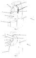
figures 1 à 4 sont des vues respectivement en perspective, en élévation latérale, en élévation frontale et de dessus d'une installation robotisée selon l'invention mise en oeuvre en relation avec une sonde de stimulation magnétique transcrânienne, - les
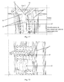
figures 5A et 5B sont des vues en perspective, selon deux angles légèrement différents, de l'installation robotisée desfigures 1 à 4 , l'enveloppe d'habillage ayant été enlevée, - la
figure 6A est un schéma cinématique équivalent d'un mode de réalisation, à quatre degrés de liberté, du dispositif robotique faisant partie de l'installation robotisée représentée auxfigures 1 à 5 ou de deux sous-ensembles constitutifs de ce dispositif, ne faisant pas partie de l'invention, - la
figure 6B est un schéma cinématique équivalent d'un mode de réalisation à sept degrés de liberté du dispositif robotique faisant partie de l'installation robotisée représentée sur lesfigures 1 à 5 , en accord avec l'invention, - les
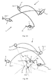
figures 7A et 7B sont des vues en perspective de l'installation robotisée desfigures 1 à 5 illustrant les positions extrêmes, respectivement supérieure et inférieure, de la première articulation rotatoire du premier sous-ensemble du dispositif robotique et montrant le mouvement au niveau de cette articulation, - les
figures 8A, 8B, 8C et 8D sont des vues similaires à celles desfigures 7A et 7B illustrant quatre positions décalées successivement de 90° de la deuxième articulation rotatoire du premier sous-ensemble du dispositif robotique et montrant le mouvement au niveau de cette articulation, - les
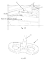
figures 9A et 9B sont des vues similaires à celle de lafigure 8D illustrant les positions extrêmes (déployée et repliée) de la troisième articulation rotatoire du premier sous-ensemble du dispositif robotique et montrant le mouvement au niveau de cette articulation, - la
figure 10 est une représentation maillée et en relief de la tête d'un patient illustrant la zone accessible pour l'organe ou instrument porté par le dispositif robotique sans qu'il y ait interférence avec le patient, - les
figures 11A et 11B sont des vues partielles en perspective selon deux angles différents, représentant le deuxième et le troisième sous-ensembles du dispositif robotique faisant partie de l'installation robotisée desfigures 1 à 5 et illustrant les deux positions extrêmes en translation du deuxième sous-ensemble du dispositif robotique et montrant son axe de déplacement, - la
figure 12 est une représentation partielle en élévation latérale de l'objet desfigures 11A et 11B illustrant les mouvements rotatoires possibles au niveau des première, deuxième et troisième articulations faisant partie du troisième sous-ensemble du dispositif robotique, - la
figure 13 est une vue partielle en perspective du troisième sous-ensemble du dispositif robotique faisant partie de l'installation robotisée, certains des éléments constitutifs présentant une structure et un arrangement légèrement différent du troisième sous-ensemble représenté auxfigures 11A, 11B et 12 , - la
figure 14 est une vue partielle du dessus de l'installation robotisée telle que représentée auxfigures 5A et 5B montrant partiellement certains éléments des articulations du premier sous-ensemble du dispositif robotique, - la
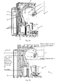
figure 15 est une vue partielle en élévation latérale de l'installation robotisée telle que représentée à lafigure 5 montrant plus particulièrement les deuxième et troisième articulations rotatoires du premier sous-ensemble du dispositif robotique, ainsi que l'articulation coulissante formant le deuxième sous-ensemble du dispositif robotique, - la
figure 16 est une vue partielle de détail et en perspective de l'installation robotisée telle que représentée à lafigure 5 montrant plus particulièrement le siège formant dispositif de support et de maintien du patient, ainsi que les dispositifs de réglages vertical et horizontal qui lui sont associés, - les
figures 17 et 18 sont des vues partielles de détail et en perspective de l'installation robotisée telle que représentée à lafigure 5 montrant plus particulièrement les éléments constitutifs du dispositif de sécurité associé à la première articulation rotatoire du premier sous-ensemble du dispositif robotique et réalisé sous la forme d'un mécanisme de rappel à tension constante, - les
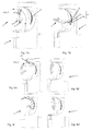
figures 19 et 20 sont des vues partielles de détail et en perspective de l'installation robotisée telle que représentée à lafigure 5 montrant plus particulièrement les éléments constitutifs des première et deuxième articulations rotatoires du premier sous-ensemble du dispositif robotique, - les
figures 21A, 21B ,21C, 21D et21E sont des vues partielles de détail et en perspective de l'installation robotisée telle que représentée à lafigure 5 montrant plus particulièrement les éléments du circuit de circulation d'air pour le refroidissement de la sonde, ainsi que le câble d'alimentation de la sonde, au niveau de la deuxième articulation rotatoire du premier sous-ensemble du dispositif robotique, et, - la
figure 22 est une vue en perspective d'une sonde de stimulation magnétique transcrânienne faisant partie d'un appareil de traitement comprenant l'installation robotisée représentée auxfigures 1 à 5 .
- the
Figures 1 to 4 are views respectively in perspective, in side elevation, in front elevation and from above of a robotic installation according to the invention implemented in connection with a transcranial magnetic stimulation probe, - the
Figures 5A and 5B are perspective views, from two slightly different angles, of the robotic installation ofFigures 1 to 4 the covering envelope having been removed, - the
Figure 6A is an equivalent kinematic diagram of an embodiment, with four degrees of freedom, of the robotic device forming part of the robotic installation represented in FIGS.Figures 1 to 5 or of two constituent subassemblies of this device, not forming part of the invention, - the
Figure 6B is an equivalent kinematic diagram of an embodiment with seven degrees of freedom of the robotic device forming part of the robotic installation represented on theFigures 1 to 5 , according to the invention, - the
Figures 7A and 7B are perspective views of the robotic installation ofFigures 1 to 5 illustrating the extreme positions, respectively upper and lower, of the first rotary joint of the first subset of the robotic device and showing the movement at this joint, - the
FIGS. 8A, 8B, 8C and 8D are views similar to those ofFigures 7A and 7B illustrating four positions successively offset by 90 ° from the second rotary articulation of the first subset of the robotic device and showing the movement at this articulation, - the
Figures 9A and 9B are views similar to that of thefigure 8D illustrating the extreme positions (deployed and folded) of the third rotary joint of the first subset of the robotic device and showing the movement at this joint, - the
figure 10 is a meshed representation and relief of the head of a patient illustrating the accessible area for the organ or instrument carried by the robotic device without interference with the patient, - the
Figures 11A and 11B are partial perspective views from two different angles, representing the second and third subsets of the robotic device forming part of the robotic installation of theFigures 1 to 5 and illustrating the two extreme positions in translation of the second subset of the robotic device and showing its axis of displacement, - the
figure 12 is a partial representation in side elevation of the object of theFigures 11A and 11B illustrating the possible rotary movements at the first, second and third joints forming part of the third subset of the robotic device, - the
figure 13 is a partial perspective view of the third subset of the robotic device forming part of the robotic installation, some of the constituent elements having a slightly different structure and arrangement of the third subassembly shown in FIGS.Figures 11A, 11B and 12 , - the
figure 14 is a partial view of the top of the robotic installation as shown inFigures 5A and 5B partially showing some elements of the joints of the first subset of the robotic device, - the
figure 15 is a partial side elevation of the robotic installation as shown in FIG.figure 5 showing more particularly the second and third rotary joints of the first subset of the robotic device, as well as the sliding joint forming the second subset of the robotic device, - the
figure 16 is a partial detail and perspective view of the robotic installation as shown in FIG.figure 5 showing more particularly the patient support and holding device seat, as well as the vertical and horizontal adjustment devices associated with it, - the
Figures 17 and 18 are partial views of detail and perspective of the robotic installation as shown in thefigure 5 showing more particularly the constituent elements of the safety device associated with the first rotary articulation of the first subset of the robotic device and embodied in the form of a constant voltage return mechanism, - the
Figures 19 and 20 are partial views of detail and perspective of the robotic installation as shown in thefigure 5 showing more particularly the constituent elements of the first and second rotary joints of the first subset of the robotic device, - the
Figures 21A, 21B ,21C, 21D and21E are partial views of detail and perspective of the robotic installation as shown in thefigure 5 showing more particularly the elements of the air circulation circuit for the cooling of the probe, as well as the supply cable of the probe, at the level of the second rotary joint of the first subset of the robotic device, and, - the
figure 22 is a perspective view of a transcranial magnetic stimulation probe forming part of a treatment apparatus comprising the robotic installation shown in FIGS.Figures 1 to 5 .
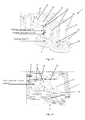
Ces dernières montrent une installation robotisée 1 pour le positionnement et le déplacement guidés et contrôlés d'un organe ou instrument 2 de traitement, du type sonde de stimulation magnétique transcrânienne ou analogue, au niveau ou autour de la tête 3 d'un patient 3'.The latter show a
Cette installation 1 comprend essentiellement une structure support (bâti) 4, revêtue d'une enveloppe d'habillage et de protection 4' et sur laquelle sont montés les éléments constitutifs 7 à 31 d'un dispositif robotique 5 formant une chaîne cinématique série et portant à son extrémité libre et contrôlée en position la sonde 2 précitée. De plus, un dispositif 6 réglable de support et de maintien du patient 3', sensiblement en position assise, fait partie de ou est associé à ladite structure support 4.This
Conformément à l'invention, ledit dispositif robotique 5 est constitué de trois 7, 7', 7", sous-ensembles cinématiques mutuellement associés en série, comprenant, d'une part, un premier sous-ensemble 7 sous la forme d'un mécanisme à articulations rotatoires 8, 8', 8", solidaire de la structure support 4 par une première articulation 8 et correspondant à un arrangement cinématique sphérique de type série à trois degrés de liberté, les éléments d'articulation 8, 8', 8" étant tous situés en dehors du volume 9 susceptible de recevoir le patient 3' et leurs axes de rotation axe 1, axe 2 et axe 3 étant concourants en un point focal PF correspondant sensiblement au centre hypothétique de la tête 3 du patient 3' en position d'intervention d'autre part, un deuxième sous-ensemble 7' sous la forme d'un mécanisme à translation linéaire selon un axe (axe 4) passant par le point focal PF précité et solidaire de la partie mobile 10 de la troisième articulation 8" en série du premier sous-ensemble 7, et enfin un troisième sous ensemble 7" sous la forme d'un second mécanisme à articulations rotatoires, solidaire de la partie mobile 12 du second sous-ensemble 7' et correspondant également à un arrangement cinématique sphérique de type série à trois degrés de liberté, les éléments d'articulation 11, 11', 11" de ce troisième sous-ensemble 7" présentant des axes de rotation axe 5, axe 6, axe 7 concourants.According to the invention, said robotic device 5 consists of three 7, 7 ', 7 "mutually associated kinematic subassemblies, comprising, on the one hand, a first subassembly 7 in the form of a rotary articulation mechanism 8, 8 ', 8 ", secured to the support structure 4 by a first hinge 8 and corresponding to a spherical kinematic arrangement of the series type with three degrees of freedom, the hinge elements 8, 8', 8 "being all located outside the volume 9 capable of receiving the patient 3 'and their axes of rotation axis 1, axis 2 and axis 3 being concurrent in a focal point PF substantially corresponding to the hypothetical center of the head 3 of the patient 3' in second intervention position, a second subassembly 7 'in the form of a linear translation mechanism along an axis (axis 4) passing through the aforementioned FP focal point and secured to the movable portion 10 of the third 8 "articulation in serum ie of the first subassembly 7, and finally a third subassembly 7 "in the form of a second rotary articulation mechanism, integral with the movable portion 12 of the second subassembly 7 'and also corresponding to a spherical kinematic arrangement of series type with three degrees of freedom, the hinge elements 11, 11 ', 11 "of the third subassembly 7" having axes of rotation axis 5, axis 6, axis 7 concurrent.
La décomposition du dispositif robotique 5 en trois sous-ensembles 7, 7', 7" indépendants et reliés entre eux en série facilite la commande en position et en déplacement, augmente la précision du mouvement résultant et permet de sécuriser individuellement chacun des éléments d'articulation qui le constituent.The decomposition of the
En particulier l'association d'un premier sous-ensemble 7 à mouvement sphérique, formé de trois liaisons rotatoires ou rotoïdes en série (8/axe 1, 8'/axe 2, 8"/axe 3) et non interférant avec le volume 9 recevant le patient 3', avec un deuxième sous-ensemble 7' à mouvement en translation selon un axe (axe 4) radial par rapport à la sphère ou la partie de sphère dont les points peuvent être atteints au moyen du premier sous-ensemble 7, permet une gestion optimisée de la sécurité du dispositif robotique 5, éventuellement par le seul contrôle sécurisé de ce deuxième sous-ensemble 7'.In particular, the combination of a
En accord avec une première caractéristique de l'invention, ressortant notamment des
Le rail 13 est fixé rigidement en plusieurs endroits à la structure support 4, au niveau d'une partie supérieure en forme de potence surplombant le dispositif de support et de maintien de patient, sous forme de siège réglable 6.The
Le rail 13 peut présenter soit une structure double (
La tringlerie de transmission 15, réalisant le déplacement du chariot 14 sur le rail 13, peut comprendre comme cela ressort des
L'utilisation d'un premier sous-ensemble 7 de type mécanisme articulé sphérique série à trois degrés de liberté est particulièrement adaptée à un volume de travail de forme sphérique, tel que l'espace entourant la tête d'un patient, le positionnement de la sonde 2 étant réalisé au niveau d'une sphère centrée sur la tête du patient.The use of a
Le sous-ensemble 7 consiste selon l'invention en un arrangement particulier de guides circulaires (deux sous-assemblages concentriques à guidage circulaire reliés entre eux par un axe de rotation), évitant ainsi toute interférence avec le patient et optimisant la rigidité du dispositif pour faciliter la manipulation précise de la sonde 2.The
Les mécanismes de sécurité associés aux trois articulations rotatoires 8, 8', et 8" garantissent la sécurité du patient en cas d'incident.The safety mechanisms associated with the three
Selon une autre caractéristique de l'invention et comme le montrent les
Conformément à une autre caractéristique de l'invention, ressortant notamment des
Comme le montre à titre d'exemple de réalisation pratique la
En outre, le rail fixe 20 peut être muni d'une règle optique 34 et le rail mobile 21 d'un capteur optique correspondant 34'.In addition, the fixed
Le déplacement du rail mobile 21 par rapport au rail fixe 20 pourra être réalisé, par exemple, par l'intermédiaire d'un système à crémaillère ou à galet d'entraînement, entraîné au moyen d'une transmission adaptée par un moteur électrique porté par le rail mobile 21.The displacement of the
Comme le montrent également les figures précitées, le rail fixe 20 est assemblé rigidement avec l'arbre 17 de la seconde articulation rotatoire 8', les deux rails 20 et 21 pouvant être bloqués en position l'un par rapport à l'autre constructivement, par liaison mécanique ou par blocage de l'actionneur assurant leur mouvement relatif mutuel.As also shown in the aforementioned figures, the fixed
En cas de blocage de cette troisième articulation rotatoire 8", le premier sous-ensemble 7 constitue un mécanisme articulé sphérique à deux degrés de liberté, qui peut être suffisant pour certaines applications nécessitant une mobilité réduite pour la sonde 2.In case of blockage of this third rotary joint 8 ", the
Le blocage de cette articulation 8" peut être définitif ou temporaire, et dans ce dernier cas il pourra être obtenu consécutivement à une programmation logicielle correspondante de l'unité de commande du moteur électrique assurant la mobilité du rail 21 relativement au rail 20.The locking of this
L'arbre 17 reliant le rail 20 de manière rotatoire au chariot 14 présente préférentiellement une longueur relativement faible, de manière à réduire le porte-à-faux entre les deux éléments reliés et assurer une bonne rigidité à l'assemblage articulé réalisé.The
Afin d'éviter une possible chute du dispositif robotique 5 dans le volume 9 et d'obtenir un dégagement automatique vers le haut dudit dispositif, il peut être avantageusement prévu que le chariot mobile 14 de la première articulation rotatoire 8 soit de manière permanente sollicité en position extrême supérieure par un mécanisme de rappel à tension constante 22, par exemple à câble 22' (
De plus, en vue d'éviter tout mouvement non contrôlé des éléments fixés à l'arbre 17, pouvant éventuellement interférer avec le patient 3', un dispositif 23 de blocage en rotation de l'arbre 17 est associé à l'actionneur 19, par exemple sous la forme d'un frein actif en l'absence d'alimentation électrique au niveau de ce dernier, par exemple du type électromagnétique, ledit dispositif 23 pouvant être débloqué par un opérateur par l'intermédiaire d'une commande manuelle d'alimentation en courant, afin d'autoriser une libre rotation de l'arbre 17 autour de son axe de rotation axe 2 (
A titre de sécurité supplémentaire au niveau du premier sous-ensemble 7, il peut également être prévu que l'actionneur 21' de la troisième articulation rotatoire 8" du premier sous-ensemble 7 réalise un blocage en position mutuel des deux rails 20 et 21 en l'absence d'alimentation électrique.As additional security at the
Conformément à une caractéristique de l'invention ressortant notamment des
Le capteur d'effort peut être soit monté dans le sous-ensemble 7', soit être intégré directement dans la sonde 2.The force sensor can be either mounted in the subassembly 7 ', or integrated directly into the
En particulier dans le cas d'une sonde de stimulation magnétique transcrânienne ou analogue (sonde 2 destiné à venir en application contre la tête d'un patient), ledit capteur d'effort peut être intégré dans la sonde 2 porté par le dispositif robotique 5, ledit capteur d'effort faisant partie d'un asservissement en effort du deuxième sous-ensemble 7' dudit dispositif 5.In particular in the case of a transcranial magnetic stimulation probe or the like (
Le capteur d'effort pourra alors se présenter sous la forme d'un capteur mince en forme de portion de feuille tel que, par exemple, les capteurs connus sous la désignation FlexiForce (nom déposé) de la société Tekscan ou sous la désignation FSR (nom déposé) de la société Interlink Electronics. Ce capteur sera insensible au rayonnement éventuellement émis par la sonde 2.The force sensor may then be in the form of a thin sheet-shaped sensor such as, for example, the sensors known by the name FlexiForce (registered name) of the company Tekscan or under the designation FSR ( registered name) of Interlink Electronics. This sensor will be insensitive to the radiation possibly emitted by the
La
Selon une première variante de réalisation ne faisant pas partie de l'invention, représentée de manière schématique et cinématique sur la
En accord avec l'invention ressortant des
Un tel dispositif robotique présente non seulement les mêmes propriétés que la première variante précitée (qu'elle intègre), mais permet également de réaliser une orientation locale de la sonde 2 par rapport à un point de référence donné PR, par exemple le point de contact ou point central de la surface de contact entre la sonde 2 et la tête 3 du patient 3' (éventuellement confondu avec le point central de la sonde 2).Such a robotic device has not only the same properties as the aforementioned first variant (which it integrates), but also makes it possible to achieve a local orientation of the
Cette propriété supplémentaire est notamment nécessaire dans le cadre de la stimulation magnétique transcrânienne pour assurer la condition de tangence entre la sonde 2 et la tête 3 durant la procédure de traitement nécessitant un mouvement de balayage contrôlé de ladite sonde.This additional property is particularly necessary in the context of transcranial magnetic stimulation to ensure the tangency condition between the
En accord avec une construction pratique de l'invention, représentée plus particulièrement aux
L'actionneur 36 (par exemple un moteur électrique) assurant le déplacement des rails mobiles 29 dans les chariots 28 peut, par exemple, être porté par les bras 27, la transmission du mouvement étant assurée à travers ou autour de ces dernières (cabestans).The actuator 36 (for example an electric motor) ensuring the displacement of the
De même, l'actionneur 37 (moteur électrique) assurant la rotation de la sonde 2 autour de son moyeu 31 (axe 7) pourra être directement porté par la platine à palier 30 recevant la sonde 2.Similarly, the actuator 37 (electric motor) ensuring the rotation of the
Les plages angulaires maximales pour les articulations 11, 11' et 11" formant le troisième sous-ensemble 7", ainsi que pour les articulations 8, 8' et 8", sont déterminées lors de la conception du dispositif robotique 5 en évaluant (sur la base d'une reconstitution tridimensionnelle de la tête du patient à partir d'images IRM par exemple) les angles nécessaires pour assurer la tangence de la face frontale de la sonde 2 au niveau des différentes régions de la tête à atteindre.The maximum angular ranges for the
De plus, de possibles décalages entre le centre de la tête du patient et le point focal PF sont également à prendre en compte dans la réalisation du sous-ensemble 7".In addition, possible offsets between the center of the patient's head and the focal point PF are also to be taken into account in the realization of the
Une description complémentaire de l'invention, en relation directe avec les dessins annexés, est présentée ci-après, plus précisément mais non limitativement, dans le cadre d'une application à la stimulation magnétique transcrânienne.A further description of the invention, in direct connection with the accompanying drawings, is presented below, more specifically but not exclusively, in the context of an application to transcranial magnetic stimulation.
Comme le montrent les
Dans le cas des figures précitées, le dispositif robotique 5 est représenté avec un effecteur (sonde 2) permettant la réalisation d'un traitement de stimulation magnétique transcrânienne (SMT).In the case of the aforementioned figures, the
Comme cela ressort des
La structure principale 7 permet le placement et le déplacement du centre de la sonde de stimulation magnétique transcrânienne 2 sur une sphère centrée sur le patient 3'. Il s'agit sur un plan cinématique d'une structure de robot série sphérique (
L'utilisation, pour la réalisation des première et troisième articulations rotatoires 8 et 8", de guidages circulaires, rend possible l'obtention de mouvements sans interférences avec le patient 3', et en assurant la rigidité nécessaire du dispositif 5.The use, for the realization of the first and third
Les déplacements maximums pouvant être obtenus au niveau de chacune des articulations 8, 8' et 8" sont indiqués sur les
Comme le montrent les
Le poignet sphérique (sous-ensemble 7" /
Le comportement du dispositif robotique 5 est sûr en cas de coupure volontaire ou involontaire de la puissance (arrêt d'urgence, fin d'utilisation, coupure de courant): l'articulation rotatoire 8 autour de l'axe 1 de mouvement en rotation revient alors en position verticale haute (
De même, le dispositif de rappel associé à la liaison glissière éloignera automatiquement la sonde de la tête 3 du patient en cas d'incident similaire.Similarly, the return device associated with the slide connection will automatically move the probe from the
Comme le montrent plus particulièrement les
La sortie du volume 9 doit cependant être possible même en cas de défaillance de l'installation robotisée 1. Si à cet instant la sonde 2 est par exemple située face au patient 3', le gênant dans son mouvement de sortie, un opérateur peut intervenir manuellement pour envoyer ponctuellement un courant dans le frein 23 et orienter manuellement le dispositif robotique 5 (dans l'une des positions des
La
La sonde comprend comme élément actif un enroulement de cuivre en forme de 8, permettant la création d'un champ magnétique intense. Le bon fonctionnement de la sonde 2 requiert son refroidissement, par exemple par circulation d'air.The probe comprises an active element 8-shaped copper winding, allowing the creation of an intense magnetic field. The proper functioning of the
En effet, la création du champ magnétique au niveau de la sonde 2 de SMT provoque l'échauffement du conducteur en cuivre qui la compose. Pour assurer un fonctionnement correct, un refroidissement doit donc être assuré.Indeed, the creation of the magnetic field at the
Par ailleurs, les mouvements du patient 3' sont détectés à l'aide d'un localisateur externe, permettant de déterminer la position et l'orientation de la tête du patient. Afin d'assurer le bon fonctionnement de ce localisateur, il est nécessaire de minimiser la présence de câbles et de flexibles autour du dispositif robotique 5. La présence de câbles pourrait de plus gêner le patient ou l'opérateur au cours de l'utilisation de l'appareil.In addition, the movements of the patient 3 'are detected with the aid of an external locator, making it possible to determine the position and orientation of the patient's head. To ensure the proper functioning of this locator, it is necessary to minimize the presence of cables and hoses around the
En conséquence, le dispositif robotique 5 est conçu de manière à intégrer un flexible permettant le refroidissement de la sonde 2 de SMT par aspiration d'air depuis un aspirateur ou dispositif à vide analogue intégré à l'installation 1, ainsi que le câble d'alimentation permettant le fonctionnement de la sonde.Consequently, the
Des exemples de solutions, pour gérer le cheminement des flexibles au niveau des deuxième et troisième articulations 8' et 8" (axe 2 et axe 3), sont représentés sur les
Au niveau de l'articulation 8' (axe 2), un joint tournant de forme torique est créé autour de la liaison pivot que constitue l'articulation 8' (axe 2 /
Pour cette articulation 8', le câble d'alimentation ne passe pas par l'axe de rotation de la liaison.For this
Afin de gérer la variation de longueur du câble qui en résulte, un système d'enroulement est mis en place. Ce système est composé d'une surface cylindrique située sur l'arbre de rotation 17 fournissant l'axe 2 (
Au niveau de l'articulation 8" (axe 3), la variation de longueur d'arc (
La mise en oeuvre de l'installation robotisée 1 selon l'invention, dans l'application SMT ou une application analogue, suppose un positionnement initial du patient 3' afin de recaler le centre PF du mécanisme principal sphérique (premier sous-ensemble 7) avec le centre de la tête 3. Le siège 6 est donc muni de deux dispositifs de réglage 32 et 32', selon des directions horizontale et verticale, associés chacun à un organe de commande manuelle 32" respectif (par exemple une manivelle). La procédure de positionnement comprendra un réglage manuel facilité par ce dispositif de réglage continu selon deux degrés de liberté, et sera basée soit sur l'estimation de la position de la tête à partir d'un localisateur externe, soit par un indication optique du centre PF du mécanisme sphérique (sous-ensemble 7) projetée sur le patient 3'.The implementation of the
Deux stratégies opératoires peuvent être envisagées après un calage initial de la tête du patient dans le volume 9 par rapport au point focal PF des premier et second sous-ensembles 7 et 7' (projection d'une croix sur le front du patient).Two operative strategies can be envisaged after an initial calibration of the patient's head in the
Selon une première possibilité, le patient et en particulier la tête du patient est maintenu en position après calage, de manière à éviter un décalage entre la trajectoire prédéterminée de la sonde 2 et les zones à traiter.According to a first possibility, the patient and in particular the patient's head is held in position after stalling, so as to avoid an offset between the predetermined trajectory of the
Selon une seconde possibilité, autorisant une certaine liberté de mouvements du patient, le patient est muni de marqueurs passifs (par exemple un bandeau à marqueurs enserrant sa tête ou un masque posé sur le visage) pouvant être détectés par des capteurs de position correspondant (par exemple deux caméras infrarouges ou optiques à 90°). Les informations de ces capteurs sont fournies de manière continue à l'unité de commande et de pilotage de l'installation robotisée 1, qui modifiera la trajectoire précalculée de la sonde 2 en fonction des possibles mouvements du patient, à la manière d'un asservissement en mouvement temps réel. Un tel système de localisation est de suivi est, par exemple, connu par la société NDI Inc. sous la désignation POLARIS.According to a second possibility, allowing a certain freedom of movement of the patient, the patient is provided with passive markers (for example a marker strip encircling his head or a mask placed on the face) that can be detected by corresponding position sensors (for example). example two infrared or optical cameras at 90 °). The information of these sensors is provided continuously to the control and control unit of the
Les différents actionneurs des articulations rotatoires des trois sous-ensembles 7, 7' et 7" consistent préférentiellement en des moteurs électriques (par exemple à courant continu ou à excitation harmonique) associés à des mécanismes de transmission et/ou de réduction du mouvement et à des capteurs de positions et/ou codeurs, bien connus dans le domaine de la robotique, l'ensemble de ces actionneurs étant piloté par une unité de commande et de pilotage adaptée, par exemple une unité informatique, calculant également et stockant la trajectoire de la sonde 2, ce à partir de données programmées ou déduites d'images antérieures.The various actuators of the rotary joints of the three
L'installation robotisée 1 selon l'invention permet ainsi de satisfaire les exigences précitées de précision (positionnement à 1 mm près) et de sécurité (active et passive), et de répondre aux contraintes associées à une procédure automatisée en milieu médical.The
La présente invention a également pour objet un appareil de traitement par stimulation magnétique transcrânienne, comprenant essentiellement une sonde 2 comprenant une bobine de stimulation magnétique et portée par une installation robotisée 1.The present invention also relates to a transcranial magnetic stimulation treatment apparatus, essentially comprising a
Cet appareil est caractérisé en ce que l'installation robotisée 1 consiste en une installation telle que décrite précédemment et illustrée à titre d'exemple aux figures annexées, et qui intègre un dispositif robotique 5 à sept degrés de liberté, lequel est apte à réaliser un positionnement et un déplacement automatiques de ladite sonde autour de la tête d'un patient en fonction d'une trajectoire déterminée préalablement, ce sous le contrôle d'une unité de commande et de pilotage.This apparatus is characterized in that the
La fourniture d'un dispositif robotique 5 avec sept degrés de liberté, c'est-à-dire un degré de liberté redondant, permet un comportement cinématique satisfaisant et la garantie d'un déplacement et d'un positionnement précis au niveau de chaque articulation, ainsi qu'une sécurité optimisée au niveau contrôle.Providing a
Préférentiellement cet appareil comprend également un système de localisation, préférentiellement en position et en orientation, de la tête 3 du patient 3' dans la volume 9 recevant le patient, coopérant avec l'unité de commande et de pilotage en vue de réaliser un calage de la tête 3 par rapport au point focal PF du premier sous-ensemble 7 du dispositif robotique 5 et un asservissement, en fonction des mouvements de la tête 3, de la position de la sonde 2 par l'intermédiaire de l'installation robotisée 1, sous le contrôle de l'unité de commande et de pilotage et en fonction des signaux ou données fourni(e)s par le système de localisation.Preferably, this apparatus also comprises a positioning system, preferably in position and in orientation, of the
Un tel appareil permet de remplacer l'opérateur durant une procédure de SMT, en garantissant la précision et la sécurité requises.Such a device allows the operator to be replaced during an SMT procedure, ensuring the accuracy and security required.
Les caractéristiques principales d'un appareil de stimulation magnétique transcrânienne du type précité ressortent notamment du document "
Enfin l'invention est utilisable dans le cadre d'un procédé de stimulation magnétique transcrânienne mettant en oeuvre l'appareil décrit ci-dessus.Finally, the invention can be used in the context of a transcranial magnetic stimulation method using the apparatus described above.
Ce procédé consiste essentiellement à réaliser successivement les étapes suivantes :
- réalisation de plusieurs images du cerveau et de la tête du patient à traiter, par exemple par IRM ou IRMf ;
- construction d'un modèle tridimensionnel du cerveau et de la tête du patient ;
- détermination des régions corticales à stimuler et de leur ordre respectif dans la séquence de stimulation, ainsi que de la fréquence, de la durée et, le cas échéant, de la puissance de stimulation pour chaque région ;
- calcul par l'unité de commande et de pilotage de l'appareil, ou par une unité de calcul externe de la trajectoire du centre fonctionnel de la bobine de la sonde autour de la tête du patient pour stimuler de façon optimale chaque région corticale concernée en fonction des spécificités prédéterminées ;
- positionnement du patient dans l'installation robotisée et réalisation du calage ou cadrage de sa tête par rapport au point focal de l'installation robotisée et au modèle tridimensionnel ;
- lancement et exécution autonome de la procédure de stimulation avec déplacement contrôlé de la sonde par le dispositif robotique, avec éventuellement acquisition de la localisation et de l'orientation de la sonde pour une analyse postérieure au traitement.
- producing several images of the brain and the head of the patient to be treated, for example by MRI or fMRI;
- constructing a three-dimensional model of the brain and the patient's head;
- determining the cortical regions to be stimulated and their respective order in the stimulation sequence, as well as the frequency, duration and, if applicable, stimulation power for each region;
- calculation by the control and control unit of the apparatus, or by an external calculation unit of the trajectory of the functional center of the coil of the probe around the patient's head in order to optimally stimulate each cortical region concerned by according to the predetermined specificities;
- positioning the patient in the robotic installation and making the wedging or framing of his head relative to the focal point of the robotic installation and to the three-dimensional model;
- launching and autonomous execution of the stimulation procedure with controlled displacement of the probe by the robotic device, possibly with acquisition of the location and orientation of the probe for post-treatment analysis.
Plus précisément, après identification des raisons corticales à stimuler, la trajectoire du centre de la bobine de la sonde 2 est calculée, ainsi que l'orientation de ladite sonde pendant la trajectoire, pour une stimulation optimale desdites régions, ce sur la base d'une reconstitution tridimensionnelle de la tête du patient.More precisely, after identification of the cortical reasons to be stimulated, the trajectory of the center of the coil of the
La vitesse de déplacement de la sonde, ainsi que la puissance, la fréquence et le nombre de séquences de stimulation par région à stimuler sont calculés ou programmés.The speed of movement of the probe, as well as the power, the frequency and the number of stimulation sequences per region to be stimulated are calculated or programmed.
Le calcul de la trajectoire requise, qui prend également en compte les contraintes physiques et mécaniques du dispositif robotique (limites angulaires de rotation des articulation, limites en terme de vitesse de rotation des articulations, évitement de collision), peut par exemple être réalisé au niveau de l'unité de commande et de pilotage par l'intermédiaire d'un algorithme de planification de mouvement probabilistique, par exemple basé sur un algorithme utilisant des échantillons et dérivé de "
Par ailleurs, une technique de contrôle de vélocité pseudo-inverse est utilisée pour réaliser le déplacement de la sonde 2 (voir par exemple : "
Bien entendu, l'invention n'est pas limitée aux modes de réalisation décrits et représentés aux dessins annexés. Des modifications restent possibles, notamment du point de vue de la constitution des divers éléments ou par substitution d'équivalents techniques, sans sortir pour autant du domaine de protection de l'invention tel que défini dans les revendications.Of course, the invention is not limited to the embodiments described and shown in the accompanying drawings. Modifications are possible, particularly from the point of view of the constitution of the various elements or by substitution of technical equivalents, without departing from the scope of the invention as defined in the claims.
Claims (14)
- Robotised installation (1) for the guided and controlled positioning and movement of a transcranial magnetic stimulation probe, at or around the head (3) of a patient (3'), wherein said installation (1) essentially comprises a support structure (4) on which are mounted the constituent elements of a robotic device (5) forming a serial kinematic chain and carrying the aforementioned probe (2) at its free and position-controlled end, an adjustable device (6) for supporting and holding the patient (3'), essentially in the seated position, forming part of or being connected to said support structure (4),
said robotic device (5) comprising two (7, 7') kinematic sub-assemblies that are mutually connected in series, namely on the one hand a first sub-assembly (7) in the form of a rotary articulation mechanism (8, 8', 8"), integral with the support structure (4) by a first articulation (8) and corresponding to a serial-type, spherical kinematic arrangement with three degrees of freedom, whereby the articulation elements (8, 8', 8") are all located outside of the space (9) that can accommodate the patient (3') and whereby their axes of rotation (axis 1, axis 2, and axis 3) are concurrent at a focal point (PF) that corresponds approximately to the hypothetical centre of the head (3) of the patient (3') in an intervention position, and, on the other hand, a second sub-assembly (7') in the form of a mechanism with linear translation along an axis (axis 4) that passes through the aforementioned focal point (PF) and that is integral with the moving part (10) of the third articulation (8") in series of the first sub-assembly (7),
the installation (1) characterised in that the robotic device (5) also comprises a third sub-assembly (7") in the form of a second rotary articulation mechanism in series (11, 11', 11") forming a spherical cuff with three degrees of freedom, said third sub-assembly (7") being connected to the mobile part (12) of the second subassembly (7') and the robotic device (5) being thus redundant at seven degrees of freedom. - Installation according to claim 1, characterised in that the first rotary articulation (8) of the first sub-assembly (7) consists in a circular sliding connection, comprising a guide rail (13), preferably a double rail, in the form of an essentially semi-circular arc, integral with the support structure (4), and a moving carriage (14) that can circulate on said rail (13) and whose movement is controlled by a transmission linkage (15) that is connected to an actuator (16), whereby the circular movement is carried out in the median plane of the patient (3) in intervention position, and said guide rail (13) has a positioning and an extension such that it extends around the head (3) of said patient (3') essentially at the rear base of the skull up to the forehead.
- Installation according to claim 2, characterised in that the second rotary articulation (8') of the first sub-assembly (7) consists of an axial articulation with a shaft (17) that is mounted to rotate in a bearing (18) that is provided in the moving carriage (14) that is part of the first rotary articulation (8), whereby the movement in rotation of said shaft is controlled by an actuator (19), for example a geared motor unit, supported by said carriage (14).
- Installation according to any one of claims 1 to 3, characterised in that the third rotary articulation (8") of the first sub-assembly (7) consists of a circular slide connection in the form of two rails (20, 21) that work in a sliding manner and that are each made in the shape of an arc, whereby said rails (20 and 21) can be moved relative to one another between a folded arrangement in which they are essentially placed on top of one another, or overlap over their entire length, and a deployed arrangement, in which they are no longer placed on top of one another except on a small part.
- Installation according to claims 3 and 4, characterised in that one (20) of the rails (20, 21) that forms the third rotary articulation (8") is assembled rigidly with the shaft (17) of the second rotary articulation (8') of the two rails (20 and 21) that can be structurally locked in position relative to one another, by mechanical connection or by locking of the actuator, ensuring their mutual relative movement.
- Installation according to any one of claims 2, 3 and 5, characterised in that the moving carriage (14) of the first rotary articulation (8) is permanently stressed in the upper end position by a constant tension return mechanism (22), for example with a cable (22').
- Installation according to any one of claims 3 and 5, characterised in that a device (23) for locking the shaft (17) in rotation is connected to the actuator (19), for example in the form of an active brake in the event of a power failure at the level of the latter, for example of the electromagnetic type, whereby said device (23) can be unlocked by an operator by means of a manual control for current supply, so as to allow a free rotation of the shaft (17) around its axis of rotation (axis 2).
- Installation according to any one of claims 4 and 5, characterised in that the actuator of the third rotary articulation (8") of the first sub-assembly (7) carries out a locking in mutual position of the two rails (20 and 21) in the event of a power failure.
- Installation according to any one of claims 1 to 8, characterised in that a stress sensor, in particular a pressure sensor, is coupled to the second sub-assembly (7'), making it possible to produce a force control of said second sub-assembly (7') in the translation direction (axis 4) that is essentially perpendicular to the surface of the head (3) of the patient (3') in intervention position, whereby this sub-assembly (7') also comprises a return mechanism, for example of the mechanical type, forcing the probe (2) remotely from the surface of the head (3) of the patient (3').
- Installation according to claim 1, characterised in that the axes of rotation (axis 5, axis 6, axis 7) of said rotary articulations (11, 11', 11") of the third sub-assembly (7") are concurrent.
- Installation according to any one of claims 1 to 10, characterised in that the third sub-assembly (7") that forms the spherical cuff essentially consists of a first articulation (11) that is formed by a rail (24) in an arc that is integral with the moving part (12) of the second sub-assembly (7') and on which a carriage (25) circulates whose movement is controlled by an actuator (26), by a second articulation (11') that is formed by two arms (27) that are mounted rigidly on the moving carriage (25) by one of their ends and each carrying at their opposite ends a stationary carriage (28) that each works with a moving rail portion (29) in the shape of an arc, and parallel between them, and by a third articulation (11") in the form of a bearing plate (30), integral with the moving rails (29) and able to accommodate with the ability to rotate (axis 7) a hub (31) that is integral with probe (2).
- Installation according to any one of claims 1 to 8, 10 and 11, characterised in that a stress sensor, in particular a pressure sensor, is integrated into the probe (2) that is carried by a robotic device (5), whereby said stress sensor is part of a force control of the second sub-assembly (7').
- Device for treatment by transcranial magnetic stimulation, essentially comprising a probe that comprises a magnetic stimulation coil and that is supported by a robotised installation, a device that is characterised in that the robotised installation (1) consists of an installation according to any one of claims 1 to 12, integrating a robotic device (5) with seven degrees of freedom, which is able to produce an automatic positioning and movement of said probe (2) around the head (3) of a patient (3') based on a previously determined path, this under the monitoring of a control and guiding unit.
- Device according to claim 13, characterised in that it also comprises a locating system, preferably in position and in orientation, of the head (3) of the patient (3') in the space (9) that accommodates the patient, working with the control and guiding unit for the purpose of carrying out an adjustment of the head (3) relative to the focal point (PF) of the first sub-assembly (7) of the robotic device (5) and a control, based on movements of the head (3), of the position of the probe (2) by means of the robotised installation (1), under the monitoring of the control and guiding unit and based on signals or data provided by the locating system.
Applications Claiming Priority (2)
| Application Number | Priority Date | Filing Date | Title |
|---|---|---|---|
| US81634306P | 2006-06-26 | 2006-06-26 | |
| PCT/FR2007/051518 WO2008001003A2 (en) | 2006-06-26 | 2007-06-26 | Robotized installation for the positioning and movement of a component or instrument, and treatment apparatus comprising such an installation |
Publications (2)
| Publication Number | Publication Date |
|---|---|
| EP2032066A2 EP2032066A2 (en) | 2009-03-11 |
| EP2032066B1 true EP2032066B1 (en) | 2016-08-24 |
Family
ID=38846013
Family Applications (1)
| Application Number | Title | Priority Date | Filing Date |
|---|---|---|---|
| EP07803940.1A Active EP2032066B1 (en) | 2006-06-26 | 2007-06-26 | Robotized installation for the positioning and movement of a component or instrument, and treatment apparatus comprising such an installation |
Country Status (5)
| Country | Link |
|---|---|
| US (1) | US8303478B2 (en) |
| EP (1) | EP2032066B1 (en) |
| JP (1) | JP2009540999A (en) |
| CA (1) | CA2655433C (en) |
| WO (1) | WO2008001003A2 (en) |
Families Citing this family (44)
| Publication number | Priority date | Publication date | Assignee | Title |
|---|---|---|---|---|
| GB2454017A (en) * | 2007-10-26 | 2009-04-29 | Prosurgics Ltd | A control assembly |
| GB0804633D0 (en) * | 2008-03-12 | 2008-04-16 | Prosurgics Ltd | a telescopic support |
| DE102008022921A1 (en) * | 2008-05-09 | 2009-11-12 | Siemens Aktiengesellschaft | Arrangement and method for positioning devices |
| JP5622153B2 (en) | 2009-06-15 | 2014-11-12 | 国立大学法人大阪大学 | Magnetic stimulator |
| RU2525509C2 (en) * | 2009-12-25 | 2014-08-20 | АйЭйчАй КОРПОРЕЙШН | Magnetic body and drug delivery control unit using magnetic body |
| FR2974322B1 (en) * | 2011-04-22 | 2013-05-31 | Gemon Jean Pierre | MACHINING ROBOT |
| EP2772281B1 (en) | 2011-10-24 | 2021-01-06 | Teijin Pharma Limited | Transcranial magnetic stimulation system |
| GB2498943A (en) * | 2012-01-31 | 2013-08-07 | Ibm | Evaluating and optimizing a trajectory function |
| CN107212922B (en) | 2012-06-01 | 2020-06-02 | 直观外科手术操作公司 | Redundant axes and degrees of freedom of hardware constrained remote center robotic manipulators |
| KR101310530B1 (en) | 2012-07-18 | 2013-10-14 | 한국 한의학 연구원 | Apparatus and method to measure pulse |
| ITUD20120161A1 (en) * | 2012-09-20 | 2014-03-21 | Asa S R L | EQUIPMENT FOR EMITTING THERAPEUTIC RADIATIONS |
| ES2768426T3 (en) * | 2013-11-29 | 2020-06-22 | Nexstim Oyj | Device support apparatus |
| FI125610B (en) | 2013-11-29 | 2015-12-15 | Nexstim Oy | Support device for transcranial magnetic stimulation device |
| WO2016022347A1 (en) * | 2014-08-04 | 2016-02-11 | Brachium, Inc. | A medical robotic works station |
| JP6367348B2 (en) * | 2014-10-07 | 2018-08-01 | 帝人ファーマ株式会社 | Transcranial magnetic stimulation system |
| CN107106860B (en) | 2014-10-07 | 2020-09-22 | 帝人制药株式会社 | Transcranial magnetic stimulation system |
| CN104436443B (en) * | 2014-11-20 | 2017-02-22 | 西安索立德医疗科技有限公司 | Cerebral cortex transcranial magnetic stimulation three-dimensional positioning navigation system and method |
| CN104474636B (en) * | 2014-11-20 | 2017-02-22 | 西安索立德医疗科技有限公司 | Multi-point multi-frequency three-dimensional transcranial magnetic stimulation system and intracranial and extracranial coordinate conversion method |
| KR101622539B1 (en) * | 2015-01-21 | 2016-05-19 | 삼성전자 주식회사 | Brake apparatus and medical apparatus having the same |
| KR101670735B1 (en) * | 2015-02-27 | 2016-10-31 | 한국과학기술연구원 | Robot for controlling position of moving platform and System for stimulating living body having the same |
| WO2017005277A1 (en) | 2015-07-03 | 2017-01-12 | Ophthorobotics Ag | Intraocular injection system and methods for controlling such a system |
| AT517737B1 (en) * | 2015-10-02 | 2018-07-15 | Pontemed Ag | Magnetic stimulation device |
| EP3374021B1 (en) * | 2015-11-09 | 2019-08-28 | Axilum Robotics (Société par Actions Simplifiée) | Magnetic stimulation device comprising a force-sensing resistor |
| WO2017175685A1 (en) * | 2016-04-06 | 2017-10-12 | 帝人ファーマ株式会社 | Transcranial magnetic stimulation system, and positioning assistance method, and program |
| US11247039B2 (en) | 2016-05-03 | 2022-02-15 | Btl Healthcare Technologies A.S. | Device including RF source of energy and vacuum system |
| US10434322B2 (en) | 2016-05-17 | 2019-10-08 | Center Of Human-Centered Interaction For Coexistence | Robot for controlling position of motion platform and bio-stimulation system having the same |
| US10583287B2 (en) | 2016-05-23 | 2020-03-10 | Btl Medical Technologies S.R.O. | Systems and methods for tissue treatment |
| US10556122B1 (en) | 2016-07-01 | 2020-02-11 | Btl Medical Technologies S.R.O. | Aesthetic method of biological structure treatment by magnetic field |
| CN115869063A (en) * | 2016-10-04 | 2023-03-31 | 直观外科手术操作公司 | Computer-assisted teleoperated surgical systems and methods |
| WO2018165285A1 (en) * | 2017-03-09 | 2018-09-13 | Carestream Health, Inc. | Bearing system for cone beam computed tomography |
| CN108042208B (en) * | 2017-11-15 | 2024-05-03 | 重庆金山医疗机器人有限公司 | Active arm of minimally invasive surgery robot |
| IT201800000689A1 (en) * | 2018-01-10 | 2019-07-10 | Tecres Spa | SUPPORT STRUCTURE FOR A SURGICAL DEVICE AND RELATIVE POSITIONING METHOD |
| CN108161485B (en) * | 2018-02-08 | 2024-01-23 | 北部湾大学 | Teaching type five-axis numerical control machine tool |
| CN108670411B (en) * | 2018-06-04 | 2019-08-02 | 哈尔滨工业大学 | A kind of space apocenter movement mechanism using Double-stroke arc-shaped slide rail |
| CN109224301B (en) * | 2018-11-05 | 2023-09-01 | 长春大学 | Transcranial magnetic stimulation device and method with accurate positioning and automatic tracking functions |
| JP7129963B2 (en) * | 2019-09-30 | 2022-09-02 | 富士フイルム株式会社 | radiography equipment |
| US11878167B2 (en) | 2020-05-04 | 2024-01-23 | Btl Healthcare Technologies A.S. | Device and method for unattended treatment of a patient |
| WO2021224678A1 (en) | 2020-05-04 | 2021-11-11 | Btl Medical Technologies S.R.O. | Device and method for unattended treatment of a patient |
| CN111728715A (en) * | 2020-06-08 | 2020-10-02 | 南京伟思医疗科技股份有限公司 | Automatic following mechanism of support |
| CN111956960B (en) * | 2020-08-19 | 2022-05-24 | 北京石油化工学院 | Dynamic positioning device of high-intensity focused ultrasound treatment system |
| CN112546447B (en) * | 2020-11-24 | 2021-07-27 | 四川君健万峰医疗器械有限责任公司 | Stimulating coil positioning device |
| US11896816B2 (en) | 2021-11-03 | 2024-02-13 | Btl Healthcare Technologies A.S. | Device and method for unattended treatment of a patient |
| CN115089304B (en) * | 2022-06-28 | 2024-03-26 | 吉林大学 | Multi-arm multi-degree-of-freedom minimally invasive surgery platform |
| CN116392158B (en) * | 2023-06-09 | 2023-08-22 | 北京唯迈医疗设备有限公司 | Physical model DSA control and feedback device |
Family Cites Families (12)
| Publication number | Priority date | Publication date | Assignee | Title |
|---|---|---|---|---|
| US5417210A (en) * | 1992-05-27 | 1995-05-23 | International Business Machines Corporation | System and method for augmentation of endoscopic surgery |
| AU1525400A (en) * | 1998-11-18 | 2000-06-05 | Microdexterity Systems, Inc. | Medical manipulator for use with an imaging device |
| JP4398528B2 (en) * | 1999-02-12 | 2010-01-13 | 株式会社東芝 | Radiation diagnostic equipment |
| DE19926977A1 (en) | 1999-06-14 | 2001-01-04 | Siemens Ag | X-ray unit |
| US6590953B2 (en) * | 2000-09-12 | 2003-07-08 | Hitachi Medical Corporation | X-ray CT scanner |
| EP1269913B1 (en) * | 2001-06-28 | 2004-08-04 | BrainLAB AG | Device for transcranial magnetic stimulation and cortical cartography |
| WO2003098268A1 (en) * | 2002-05-17 | 2003-11-27 | Musc Foundation For Research Development | Method, apparatus, and system for automatically positioning a probe or sensor |
| DE10242542A1 (en) | 2002-09-13 | 2004-04-01 | Forschungszentrum Karlsruhe Gmbh | Positioning system for navigated trans-cranial magnetic stimulation has support with fixing elements for head that do not restrict field of view, frame with motorized stimulation coil positioning |
| US7313430B2 (en) * | 2003-08-28 | 2007-12-25 | Medtronic Navigation, Inc. | Method and apparatus for performing stereotactic surgery |
| US7520848B2 (en) * | 2004-04-09 | 2009-04-21 | The Board Of Trustees Of The Leland Stanford Junior University | Robotic apparatus for targeting and producing deep, focused transcranial magnetic stimulation |
| US8177702B2 (en) * | 2004-04-15 | 2012-05-15 | Neuronetics, Inc. | Method and apparatus for determining the proximity of a TMS coil to a subject's head |
| US8088058B2 (en) * | 2005-01-20 | 2012-01-03 | Neuronetics, Inc. | Articulating arm |
-
2007
- 2007-06-26 EP EP07803940.1A patent/EP2032066B1/en active Active
- 2007-06-26 CA CA2655433A patent/CA2655433C/en active Active
- 2007-06-26 WO PCT/FR2007/051518 patent/WO2008001003A2/en active Application Filing
- 2007-06-26 US US12/306,806 patent/US8303478B2/en active Active
- 2007-06-26 JP JP2009517348A patent/JP2009540999A/en not_active Withdrawn
Also Published As
| Publication number | Publication date |
|---|---|
| JP2009540999A (en) | 2009-11-26 |
| EP2032066A2 (en) | 2009-03-11 |
| WO2008001003A3 (en) | 2008-06-19 |
| WO2008001003A2 (en) | 2008-01-03 |
| CA2655433A1 (en) | 2008-01-03 |
| US8303478B2 (en) | 2012-11-06 |
| US20090216067A1 (en) | 2009-08-27 |
| CA2655433C (en) | 2014-11-18 |
Similar Documents
| Publication | Publication Date | Title |
|---|---|---|
| EP2032066B1 (en) | Robotized installation for the positioning and movement of a component or instrument, and treatment apparatus comprising such an installation | |
| EP2376012B1 (en) | Device for positioning a patient relative to a radiation | |
| EP3128894B1 (en) | Phoropter, and method for measuring refraction using a phoroptor of said type | |
| EP2042076B1 (en) | Guidable structure such as a catheter or an endoscope | |
| US8679101B2 (en) | Method and system for temporary hair removal | |
| FR2945724A1 (en) | X-RAY APPARATUS | |
| US8540701B2 (en) | Hair treatment system | |
| FR2972915A1 (en) | MULTIPLAN MEDICAL IMAGING SYSTEM | |
| EP2822446B1 (en) | Motorised and modular instrumentation device and endoscopy system comprising such a device | |
| WO2015189531A2 (en) | Robotized module for guiding an elongate flexible medical device | |
| CA2734418A1 (en) | Portable electric tool equipped with a device enabling the relative position of two members of said tool at least one of which can move to be determined | |
| EP3109014A1 (en) | Motorised articulated arm with cable capstan comprising a brake | |
| EP2303098A1 (en) | Device for the controlled translational displacement of an elongate element | |
| US20080091187A1 (en) | Hair treatment system | |
| EP2726258B1 (en) | Robotized system for displacing a remotely guided tool | |
| FR3037249A1 (en) | ROBOTIC METHOD FOR CATHETER TRAINING AND CATHETER GUIDE | |
| US20060200114A1 (en) | Hair removal system with light source array | |
| EP2512346A1 (en) | Dental x-ray apparatus providing a cephalometric image and related method | |
| EP0265470B1 (en) | Systematized treatment instrument, using particularly laser energy, useful for example in dermatology | |
| EP2124709B1 (en) | Flexible endoscope device with visual control | |
| FR2982759A1 (en) | PANORAMIC DENTAL RADIOLOGY APPARATUS | |
| EP2377466B1 (en) | Pulse wave treatment device equipped with a system to move the archway of an X-ray imaging system | |
| FR2648383A1 (en) | Local system for cutting using a laser beam | |
| WO2022003154A1 (en) | Robotic device for guiding a robotic arm | |
| FR2875282A1 (en) | AXIALLY ORIENTABLE AND RIGID TORSION MECHANICAL TRANSMISSION |
Legal Events
| Date | Code | Title | Description |
|---|---|---|---|
| PUAI | Public reference made under article 153(3) epc to a published international application that has entered the european phase |
Free format text: ORIGINAL CODE: 0009012 |
|
| 17P | Request for examination filed |
Effective date: 20081219 |
|
| AK | Designated contracting states |
Kind code of ref document: A2 Designated state(s): AT BE BG CH CY CZ DE DK EE ES FI FR GB GR HU IE IS IT LI LT LU LV MC MT NL PL PT RO SE SI SK TR |
|
| AX | Request for extension of the european patent |
Extension state: AL BA HR MK RS |
|
| RIN1 | Information on inventor provided before grant (corrected) |
Inventor name: LAROCHE, EDOUARD Inventor name: BAYLE, BERNARD Inventor name: RENAUD, PIERRE Inventor name: LEBOSSE, CYRILLE Inventor name: PICCIN, OLIVIER Inventor name: DE MATHELIN, MICHEL |
|
| DAX | Request for extension of the european patent (deleted) | ||
| RAP1 | Party data changed (applicant data changed or rights of an application transferred) |
Owner name: UNIVERSITE DE STRASBOURG (ETABLISSEMENT PUBLIC NAT Owner name: INSTITUT NATIONAL DES SCIENCES APPLIQUEES (ETABLIS Owner name: CENTRE NATIONAL DE LA RECHERCHE SCIENTIFIQUE (CNRS |
|
| 111L | Licence recorded |
Designated state(s): AT BE BG CH CY CZ DE DK EE ES FI FR GB GR HU IE IS IT LT LU LV MC MT NL PL PT RO SE SI SK TR Free format text: EXCLUSIVE LICENSE Name of requester: AXILUM ROBOTICS SAS, FR Effective date: 20140408 |
|
| 17Q | First examination report despatched |
Effective date: 20141010 |
|
| REG | Reference to a national code |
Ref country code: DE Ref legal event code: R079 Ref document number: 602007047625 Country of ref document: DE Free format text: PREVIOUS MAIN CLASS: A61B0019000000 Ipc: A61N0002000000 |
|
| GRAP | Despatch of communication of intention to grant a patent |
Free format text: ORIGINAL CODE: EPIDOSNIGR1 |
|
| RIC1 | Information provided on ipc code assigned before grant |
Ipc: A61N 5/01 20060101ALI20160308BHEP Ipc: A61B 90/11 20160101ALI20160308BHEP Ipc: A61B 34/35 20160101ALI20160308BHEP Ipc: A61B 90/50 20160101ALI20160308BHEP Ipc: A61N 2/00 20060101AFI20160308BHEP |
|
| INTG | Intention to grant announced |
Effective date: 20160321 |
|
| RIN1 | Information on inventor provided before grant (corrected) |
Inventor name: LEBOSSE, CYRILLE Inventor name: LAROCHE, EDOUARD Inventor name: PICCIN, OLIVIER Inventor name: BAYLE, BERNARD Inventor name: RENAUD, PIERRE Inventor name: DE MATHELIN, MICHEL |
|
| GRAS | Grant fee paid |
Free format text: ORIGINAL CODE: EPIDOSNIGR3 |
|
| GRAA | (expected) grant |
Free format text: ORIGINAL CODE: 0009210 |
|
| 111L | Licence recorded |
Designated state(s): AT BE BG CH CY CZ DE DK EE ES FI FR GB GR HU IE IS IT LT LU LV MC MT NL PL PT RO SE SI SK TR Free format text: EXCLUSIVE LICENSE Name of requester: AXILUM ROBOTICS SAS, FR Effective date: 20140408 |
|
| AK | Designated contracting states |
Kind code of ref document: B1 Designated state(s): AT BE BG CH CY CZ DE DK EE ES FI FR GB GR HU IE IS IT LI LT LU LV MC MT NL PL PT RO SE SI SK TR |
|
| REG | Reference to a national code |
Ref country code: GB Ref legal event code: FG4D Free format text: NOT ENGLISH |
|
| REG | Reference to a national code |
Ref country code: CH Ref legal event code: EP Ref country code: CH Ref legal event code: PK Free format text: COMPLETEMENT D'ENREGISTREMENT DE LICENCE: LICENCE EXCLUSIVE |
|
| REG | Reference to a national code |
Ref country code: AT Ref legal event code: REF Ref document number: 822535 Country of ref document: AT Kind code of ref document: T Effective date: 20160915 |
|
| REG | Reference to a national code |
Ref country code: IE Ref legal event code: FG4D Free format text: LANGUAGE OF EP DOCUMENT: FRENCH |
|
| REG | Reference to a national code |
Ref country code: DE Ref legal event code: R096 Ref document number: 602007047625 Country of ref document: DE |
|
| REG | Reference to a national code |
Ref country code: LT Ref legal event code: MG4D |
|
| REG | Reference to a national code |
Ref country code: NL Ref legal event code: MP Effective date: 20160824 |
|
| REG | Reference to a national code |
Ref country code: AT Ref legal event code: MK05 Ref document number: 822535 Country of ref document: AT Kind code of ref document: T Effective date: 20160824 |
|
| PG25 | Lapsed in a contracting state [announced via postgrant information from national office to epo] |
Ref country code: IT Free format text: LAPSE BECAUSE OF FAILURE TO SUBMIT A TRANSLATION OF THE DESCRIPTION OR TO PAY THE FEE WITHIN THE PRESCRIBED TIME-LIMIT Effective date: 20160824 Ref country code: NL Free format text: LAPSE BECAUSE OF FAILURE TO SUBMIT A TRANSLATION OF THE DESCRIPTION OR TO PAY THE FEE WITHIN THE PRESCRIBED TIME-LIMIT Effective date: 20160824 Ref country code: LT Free format text: LAPSE BECAUSE OF FAILURE TO SUBMIT A TRANSLATION OF THE DESCRIPTION OR TO PAY THE FEE WITHIN THE PRESCRIBED TIME-LIMIT Effective date: 20160824 Ref country code: FI Free format text: LAPSE BECAUSE OF FAILURE TO SUBMIT A TRANSLATION OF THE DESCRIPTION OR TO PAY THE FEE WITHIN THE PRESCRIBED TIME-LIMIT Effective date: 20160824 |
|
| PG25 | Lapsed in a contracting state [announced via postgrant information from national office to epo] |
Ref country code: LV Free format text: LAPSE BECAUSE OF FAILURE TO SUBMIT A TRANSLATION OF THE DESCRIPTION OR TO PAY THE FEE WITHIN THE PRESCRIBED TIME-LIMIT Effective date: 20160824 Ref country code: PT Free format text: LAPSE BECAUSE OF FAILURE TO SUBMIT A TRANSLATION OF THE DESCRIPTION OR TO PAY THE FEE WITHIN THE PRESCRIBED TIME-LIMIT Effective date: 20161226 Ref country code: AT Free format text: LAPSE BECAUSE OF FAILURE TO SUBMIT A TRANSLATION OF THE DESCRIPTION OR TO PAY THE FEE WITHIN THE PRESCRIBED TIME-LIMIT Effective date: 20160824 Ref country code: ES Free format text: LAPSE BECAUSE OF FAILURE TO SUBMIT A TRANSLATION OF THE DESCRIPTION OR TO PAY THE FEE WITHIN THE PRESCRIBED TIME-LIMIT Effective date: 20160824 Ref country code: SE Free format text: LAPSE BECAUSE OF FAILURE TO SUBMIT A TRANSLATION OF THE DESCRIPTION OR TO PAY THE FEE WITHIN THE PRESCRIBED TIME-LIMIT Effective date: 20160824 Ref country code: GR Free format text: LAPSE BECAUSE OF FAILURE TO SUBMIT A TRANSLATION OF THE DESCRIPTION OR TO PAY THE FEE WITHIN THE PRESCRIBED TIME-LIMIT Effective date: 20161125 |
|
| PG25 | Lapsed in a contracting state [announced via postgrant information from national office to epo] |
Ref country code: EE Free format text: LAPSE BECAUSE OF FAILURE TO SUBMIT A TRANSLATION OF THE DESCRIPTION OR TO PAY THE FEE WITHIN THE PRESCRIBED TIME-LIMIT Effective date: 20160824 Ref country code: RO Free format text: LAPSE BECAUSE OF FAILURE TO SUBMIT A TRANSLATION OF THE DESCRIPTION OR TO PAY THE FEE WITHIN THE PRESCRIBED TIME-LIMIT Effective date: 20160824 |
|
| REG | Reference to a national code |
Ref country code: FR Ref legal event code: PLFP Year of fee payment: 11 |
|
| REG | Reference to a national code |
Ref country code: DE Ref legal event code: R097 Ref document number: 602007047625 Country of ref document: DE |
|
| PG25 | Lapsed in a contracting state [announced via postgrant information from national office to epo] |
Ref country code: BG Free format text: LAPSE BECAUSE OF FAILURE TO SUBMIT A TRANSLATION OF THE DESCRIPTION OR TO PAY THE FEE WITHIN THE PRESCRIBED TIME-LIMIT Effective date: 20161124 Ref country code: CZ Free format text: LAPSE BECAUSE OF FAILURE TO SUBMIT A TRANSLATION OF THE DESCRIPTION OR TO PAY THE FEE WITHIN THE PRESCRIBED TIME-LIMIT Effective date: 20160824 Ref country code: PL Free format text: LAPSE BECAUSE OF FAILURE TO SUBMIT A TRANSLATION OF THE DESCRIPTION OR TO PAY THE FEE WITHIN THE PRESCRIBED TIME-LIMIT Effective date: 20160824 Ref country code: DK Free format text: LAPSE BECAUSE OF FAILURE TO SUBMIT A TRANSLATION OF THE DESCRIPTION OR TO PAY THE FEE WITHIN THE PRESCRIBED TIME-LIMIT Effective date: 20160824 Ref country code: SK Free format text: LAPSE BECAUSE OF FAILURE TO SUBMIT A TRANSLATION OF THE DESCRIPTION OR TO PAY THE FEE WITHIN THE PRESCRIBED TIME-LIMIT Effective date: 20160824 |
|
| PLBE | No opposition filed within time limit |
Free format text: ORIGINAL CODE: 0009261 |
|
| STAA | Information on the status of an ep patent application or granted ep patent |
Free format text: STATUS: NO OPPOSITION FILED WITHIN TIME LIMIT |
|
| 26N | No opposition filed |
Effective date: 20170526 |
|
| PG25 | Lapsed in a contracting state [announced via postgrant information from national office to epo] |
Ref country code: SI Free format text: LAPSE BECAUSE OF FAILURE TO SUBMIT A TRANSLATION OF THE DESCRIPTION OR TO PAY THE FEE WITHIN THE PRESCRIBED TIME-LIMIT Effective date: 20160824 |
|
| PG25 | Lapsed in a contracting state [announced via postgrant information from national office to epo] |
Ref country code: MC Free format text: LAPSE BECAUSE OF FAILURE TO SUBMIT A TRANSLATION OF THE DESCRIPTION OR TO PAY THE FEE WITHIN THE PRESCRIBED TIME-LIMIT Effective date: 20160824 |
|
| REG | Reference to a national code |
Ref country code: CH Ref legal event code: PL |
|
| REG | Reference to a national code |
Ref country code: IE Ref legal event code: MM4A |
|
| REG | Reference to a national code |
Ref country code: FR Ref legal event code: PLFP Year of fee payment: 12 |
|
| PG25 | Lapsed in a contracting state [announced via postgrant information from national office to epo] |
Ref country code: LI Free format text: LAPSE BECAUSE OF NON-PAYMENT OF DUE FEES Effective date: 20170630 Ref country code: LU Free format text: LAPSE BECAUSE OF NON-PAYMENT OF DUE FEES Effective date: 20170626 Ref country code: IE Free format text: LAPSE BECAUSE OF NON-PAYMENT OF DUE FEES Effective date: 20170626 Ref country code: CH Free format text: LAPSE BECAUSE OF NON-PAYMENT OF DUE FEES Effective date: 20170630 |
|
| REG | Reference to a national code |
Ref country code: BE Ref legal event code: MM Effective date: 20170630 |
|
| PG25 | Lapsed in a contracting state [announced via postgrant information from national office to epo] |
Ref country code: BE Free format text: LAPSE BECAUSE OF NON-PAYMENT OF DUE FEES Effective date: 20170630 |
|
| PG25 | Lapsed in a contracting state [announced via postgrant information from national office to epo] |
Ref country code: MT Free format text: LAPSE BECAUSE OF FAILURE TO SUBMIT A TRANSLATION OF THE DESCRIPTION OR TO PAY THE FEE WITHIN THE PRESCRIBED TIME-LIMIT Effective date: 20160824 |
|
| PG25 | Lapsed in a contracting state [announced via postgrant information from national office to epo] |
Ref country code: HU Free format text: LAPSE BECAUSE OF FAILURE TO SUBMIT A TRANSLATION OF THE DESCRIPTION OR TO PAY THE FEE WITHIN THE PRESCRIBED TIME-LIMIT; INVALID AB INITIO Effective date: 20070626 |
|
| PG25 | Lapsed in a contracting state [announced via postgrant information from national office to epo] |
Ref country code: CY Free format text: LAPSE BECAUSE OF NON-PAYMENT OF DUE FEES Effective date: 20160824 |
|
| PG25 | Lapsed in a contracting state [announced via postgrant information from national office to epo] |
Ref country code: TR Free format text: LAPSE BECAUSE OF FAILURE TO SUBMIT A TRANSLATION OF THE DESCRIPTION OR TO PAY THE FEE WITHIN THE PRESCRIBED TIME-LIMIT Effective date: 20160824 |
|
| PG25 | Lapsed in a contracting state [announced via postgrant information from national office to epo] |
Ref country code: IS Free format text: LAPSE BECAUSE OF FAILURE TO SUBMIT A TRANSLATION OF THE DESCRIPTION OR TO PAY THE FEE WITHIN THE PRESCRIBED TIME-LIMIT Effective date: 20161224 |
|
| PGFP | Annual fee paid to national office [announced via postgrant information from national office to epo] |
Ref country code: FR Payment date: 20230627 Year of fee payment: 17 Ref country code: DE Payment date: 20230620 Year of fee payment: 17 |
|
| PGFP | Annual fee paid to national office [announced via postgrant information from national office to epo] |
Ref country code: GB Payment date: 20230620 Year of fee payment: 17 |