EP1958738B1 - Remote diagnostic system for robots - Google Patents
Remote diagnostic system for robots Download PDFInfo
- Publication number
- EP1958738B1 EP1958738B1 EP07102279.2A EP07102279A EP1958738B1 EP 1958738 B1 EP1958738 B1 EP 1958738B1 EP 07102279 A EP07102279 A EP 07102279A EP 1958738 B1 EP1958738 B1 EP 1958738B1
- Authority
- EP
- European Patent Office
- Prior art keywords
- remote
- service
- robot
- center
- diagnostic system
- Prior art date
- Legal status (The legal status is an assumption and is not a legal conclusion. Google has not performed a legal analysis and makes no representation as to the accuracy of the status listed.)
- Active
Links
- 238000004891 communication Methods 0.000 claims description 44
- 238000012544 monitoring process Methods 0.000 claims description 13
- 238000000034 method Methods 0.000 claims description 11
- 238000004458 analytical method Methods 0.000 claims description 8
- 238000012545 processing Methods 0.000 claims description 8
- 238000013515 script Methods 0.000 claims description 7
- 230000007774 longterm Effects 0.000 claims description 4
- 238000012423 maintenance Methods 0.000 claims description 4
- 238000007726 management method Methods 0.000 claims description 4
- 238000012856 packing Methods 0.000 claims description 3
- 238000011084 recovery Methods 0.000 claims description 3
- 238000012546 transfer Methods 0.000 claims description 3
- 238000007906 compression Methods 0.000 claims description 2
- 230000006835 compression Effects 0.000 claims description 2
- 238000005457 optimization Methods 0.000 claims description 2
- 238000013024 troubleshooting Methods 0.000 claims description 2
- 238000005259 measurement Methods 0.000 claims 2
- 238000013475 authorization Methods 0.000 claims 1
- 238000004422 calculation algorithm Methods 0.000 claims 1
- 230000000977 initiatory effect Effects 0.000 claims 1
- 238000013461 design Methods 0.000 description 3
- 238000012384 transportation and delivery Methods 0.000 description 3
- 238000013480 data collection Methods 0.000 description 2
- 239000000523 sample Substances 0.000 description 2
- 238000004364 calculation method Methods 0.000 description 1
- 238000013144 data compression Methods 0.000 description 1
- 238000013500 data storage Methods 0.000 description 1
- 230000001419 dependent effect Effects 0.000 description 1
- 238000003745 diagnosis Methods 0.000 description 1
- 238000002405 diagnostic procedure Methods 0.000 description 1
- 230000000694 effects Effects 0.000 description 1
- 238000009434 installation Methods 0.000 description 1
- 230000003993 interaction Effects 0.000 description 1
- 230000004807 localization Effects 0.000 description 1
- 238000007781 pre-processing Methods 0.000 description 1
- 239000002994 raw material Substances 0.000 description 1
- 238000004171 remote diagnosis Methods 0.000 description 1
- 238000006467 substitution reaction Methods 0.000 description 1
Images


Classifications
-
- B—PERFORMING OPERATIONS; TRANSPORTING
- B25—HAND TOOLS; PORTABLE POWER-DRIVEN TOOLS; MANIPULATORS
- B25J—MANIPULATORS; CHAMBERS PROVIDED WITH MANIPULATION DEVICES
- B25J9/00—Programme-controlled manipulators
- B25J9/16—Programme controls
- B25J9/1674—Programme controls characterised by safety, monitoring, diagnostic
-
- G—PHYSICS
- G05—CONTROLLING; REGULATING
- G05B—CONTROL OR REGULATING SYSTEMS IN GENERAL; FUNCTIONAL ELEMENTS OF SUCH SYSTEMS; MONITORING OR TESTING ARRANGEMENTS FOR SUCH SYSTEMS OR ELEMENTS
- G05B2219/00—Program-control systems
- G05B2219/30—Nc systems
- G05B2219/33—Director till display
- G05B2219/33284—Remote diagnostic
-
- G—PHYSICS
- G05—CONTROLLING; REGULATING
- G05B—CONTROL OR REGULATING SYSTEMS IN GENERAL; FUNCTIONAL ELEMENTS OF SUCH SYSTEMS; MONITORING OR TESTING ARRANGEMENTS FOR SUCH SYSTEMS OR ELEMENTS
- G05B2219/00—Program-control systems
- G05B2219/30—Nc systems
- G05B2219/39—Robotics, robotics to robotics hand
- G05B2219/39412—Diagnostic of robot, estimation of parameters
Definitions
- the present invention relates to a system of monitoring a plurality of robots spread at different locations at a remote service center by means of information exchange between individual robots and the remote service center.
- Common diagnostic systems for robot controllers consist of either a computational unit in the robot controller or diagnostics computations performed in a PC connected to the robot controller.
- Common to these existing solutions is the use of a high bandwidth of data signals that flow from the controller at the diagnostics computations. Diagnostics has conventionally been performed locally at the controller or at a device which has a high bandwidth connection to the controller.
- Document WO 02/095323 A discloses a system allowing for remote maintenance and diagnostics of the work performed by e.g. an industrial robot. Diagnostics can be performed from a remote system. Any automatic diagnostics performed on the industrial robot upon an event or at a schedule time from said remote system is nowhere discussed.
- Document US 2005/010311 A1 does not disclose any diagnostics engine for automatically performing qualitative diagnostic analysis on a system individual, such as an industrial robot.
- the means (the remote diagnostics system) provided in this document enables technical support personnel to diagnose problems.
- the data collection system (100) of this disclosure enables remote configuration, diagnostics and maintenance. None is disclosed here that the system (100) is provided with diagnostics engines or tools for performing qualitative diagnostics for each individual. It is further mentioned in this document that the data collection system (100) provides a technician with all the information to diagnose a problem on-line and in real time, thus allowing the technician to resolve the problem without leaving the field service office. Accordingly, the system of this document does not disclose any means for automatically performing diagnostics on a robot connected to a remote center on a scheduled or event basis.
- a remote service center is established to perform the monitoring of a high number of robots spread at a plurality of plants at different geographic locations, an optimization of communication traffic between each individual robot of the system and the remote service center plays a major role to enable delivery of cost effective services (diagnostics) to a customer.
- One object of the present invention is to present a solution of a remote diagnostic system for delivery of remote diagnostics for robots with minimal communications costs.
- Another object of the invention is to present a solution of a remote diagnostic system for delivery of remote diagnostics for robots with a safe and high security of the communications between the individual robots and the remote service center.
- the present invention addresses problems in connection with communications and the localization of the computations in a remote diagnostic system for industrial robots.
- the present invention further addresses the issues directed to safety and security of the communications between a remote service center and industrial robots included in the system.
- One aspect of the invention is to provide each robot of the system with a service unit connected to the robot controller, wherein the service unit performs local diagnostic calculations and performs data compression.
- Said service unit is in turn connected to a remote connector server at a remote service center over a potentially low-bandwidth line or a line with high communication costs.
- the final or remaining diagnostics is performed at full computational power at said remote service center.
- Said remote service center further acts as a distribution point for information via a web browser and notification service, which allows e-mails and SMS-messages to be sent to the appropriate personnel at the robot site.
- the service units are, e.g., reprogrammable.
- Another important demand on the system is security.
- the service unit is a communication and logging unit, which has different degrees of processing power depending upon the design.
- the service unit is connected to the controller of the individual robot.
- the term "service unit” is herein only used as a term of identification.
- the functions included in the so called “service unit” can be implemented as a logic unit connected to and integrated with the robot controller. Said functions can as well be implemented as logics included in the controller or as a mix of logics internally and externally of the robot controller locally at the robot.
- a first task for the service unit is to verify the product (the industrial robot) that is connected and explicate its version.
- a second task for the service unit is to request and/or receive commands from the connector server at the remote service center with respect to what to do.
- a third task for the service box is to executes scripts and /or codes provided by the connector server. The service box will react on events, condition changes from the robot or on specific requests from a user of the remote service center.
- the connector server at the remote service center is provided with a code library storing codes for each specific service unit distributed across the remote diagnostic system.
- the connector server provides to the service unit codes/scripts on request from the service box or on demand from application performed at the connector server or from an end user.
- the communications infrastructure is responsible for transferring packets of information, in both directions, between the locally disposed robot, here called the local site, and the remote service center, here sometimes referred to as the remote site.
- An event scheme wherein a service unit automatically requests diagnostic information from the remote service center, can be described as:
- This access point can take the form of e.g. a VPN router or other piece of equipment allowing secure access to the remote service center.
- the solution according to the invention solves a problem with diagnostic activities at a remote site.
- Controller data is very awkward, as it is very processor intensive. Such data would be difficult to transfer in a cheap way to a remote site.
- One purpose with the service unit is to provide compression of controller data. Another purpose would be to perform packing of data.
- Other aspects regarding the service unit is that it should be non-intrusive, generic and reprogrammable. These aspects are important to achieve the adaptiveness and the flexibility of the remote diagnostic system, which provides services and diagnostics to a large and non homogeneous robot population (i.e. a large installed base of different products and versions of robots).
- controller data is compressed, possibly packaged and possibly preprocessed, cheap communication lines, such as internet or GPRS, can be used to arrive at a cost-effective system and thus enable the realization of the remote service center.
- cheap communication lines such as internet or GPRS
- the remote service center could be viewed as a Global service center and is a central hub for the system.
- This hub clearly comprises a web site and servers for the web site, as well as a database for customer information.
- the hub may have diagnostic tools for performing diagnostics of a robot at said local site and other tools for remotely connecting to a robot controller via the service unit at a local site.
- One object of the invention is to make it possible to provide robots without logics for monitoring purposes and in this way perform robots of a cheaper design.
- monitoring tools such as diagnostic units can be reached for performing said monitoring of the robot.
- the robot can get access to all monitoring and diagnostic tools available at the remote service center, wherein these tools are updated and of the latest design, which in turn make it unnecessary to provide the local robot controller with costly local diagnostic tools and a need of frequent robot software updates.
- the general architecture of the remote service center is structured to function as, among others, a central data storage with a web interface.
- a device logic layer will make the interface with customer equipment and will handle the communication between the servers and databases at the remote service center and the local site at the customer.
- FIG. 1 shows a brief overview of the remote diagnostic system for robots according to one aspect of the invention and is explained more in detail in the following.
- a robot 1 at a customer site, herein called a local site 2 depicted in the system represents only one of the plurality of robots that can be included at the local site in the system.
- the local site 2 further represents a plurality of local sites (at least two), which can be included in the remote diagnostic system.
- robot services provide all the interfaces between the local site 2 and the remote service center 3.
- the robot services hide all the complexity and specificity of the communication and transform robot specific data to generic data for a transfer of information between the local 2 and remote sites 3.
- the robot services is represented by a box denoted 4, which can be realized as a client server, here represented as a connector server 4.
- the robot services further, have one part at the local site (robot services client), herein referred to as a service unit and denoted 11, representing logics installed for the purpose, to handle the local process and events associated to the robot 1.
- the service unit 11 is connected to or integrated with the robot controller 1 a.
- the connector server 4 performs scheduled services, such as requesting data from a local site 2 and reception of service data from a local site 2. Crypting and encrypting data on communication with a local site 2 is also implemented at the connector server 4.
- the connector server 4 can be implemented on one or more connector servers at the remote server center 3.
- the connector server 4 checks the authority of the service unit 11 its access to the remote service center 3. Said access could, as an example, be implemented as a digital signature for the service unit 11.
- the connector server 4 further stores a code archive/library, which is provided with the codes applicable for all the service units 11 being authorized to access the connector server 4 for exchange of data via the communication line 14a. This is arranged, such that when a specific service unit 11 requests diagnostic information from the remote service center 3, the connector server 4 identifies said service unit 11 and retrieves from the code library the code for use at the specific service unit 11 and the connector server 4, whereupon said retrieved code is downloaded to the service unit 11.
- the connector server 4 can further be provided with software for pre-processing of data from the service unit 11 and software for management of said data. If data from the service unit is delivered to the connector server 4, the connector server 4 will be provided with software for de-packing data packets.
- the remote service center 3 is further provided with a current history database 12, which contains all the information needed with respect to the requests of diagnostic information.
- the main information stored and managed are client user information (profile, site, robot type, robot variant, diagnostic date, contracts, mail etc.), communication information (local equipment, communication parameters, contracts, etc.) and administration information (security, rights, scripts, etc.).
- the main purpose with the configuration database 12 is to have it provided with all information needed to have monitoring and diagnostics working, excluding all information coming from the robot 1 itself or from a support engineer, when there is a contract between a supplier of the remote service center and a client (customer) using the robot 1.
- An administrator user has to be defined to manage and set up this client user information.
- a historical database 13 is provided in the database layer 10 at the remote service center 3.
- the historical database 13 gathers all the information coming from the robot 1 system and other associated information from other actors and which needs to be kept for history or processing.
- the historical database can store customer related information, such as robot type, robot version, service performed, who the customer is, where the robot is situated, service program, etc.
- the remote service center 3 is provided with a diagnostics engine 6 equipped with processors and software for performing qualitative diagnostic analysis.
- the diagnostics engine 6 has scheduled processes attached for generating diagnostics information based on raw material stored for the specific robot 1 and on information sent from the service unit 11 via the communication line 14a. Alarms may be generated based on the result of said scheduled diagnostic processes performed for said specific robot included in the system. An alarm depending on diagnostics can be sent to the current history database 12 for storing and/or sent as an alert denoted by arrow 21.
- the diagnostics engine 6 performs analyses, trendings and predictions regarding each robot of the system and stores knowledge and history regarding the robot.
- a unit herein called a business logic layer 7, contains business related logics for the company managing the remote service center 2.
- the purpose of the business logic is to separate the database access and presentation logic from the user interface.
- the purpose is further to manage, for example, which services to be delivered, how the services is delivered to a customer (alarm, send or not by email/SMS, and to which person or addressee to send).
- a presentation layer (web site) 8 is provided for allowing end users (service technicians at a remote service center console 24) at the remote service center 3 to access, via a user interface on a network 14b at the remote service center 3, all information regarding the robot systems included in the remote service system as data per individual robot or per population of robots.
- Available robot system information includes data from the business logic layer 7, results achieved from raw data in the diagnostics engine 6, data from the databases 12 and 13 at the remote service center 3 and direct data from the service unit 11 or robot controller 1 a.
- a device layer 5 provides logic for the remote service center 3.
- This device logic layer 5 is the link between the connector server 4, the current history database 13, the history database 12, the diagnostics engine 6, the business logic layer 7 and presentation layer 8 and comprises routines for data presentation and commands.
- This device logic layer 5 has knowledge implemented to it about the robots 1 of the system and a complete behavior of the remote service center 3. The device logic layer 5 will also manage the scheduled operations of the service center 3.
- the historical database 13 contains short term and long term information for current display, temporary processing or long term statistical information and reports.
- the historical database is scalable and managed professionally at the remote service center 3.
- FIG. 2 A more detailed description of an embodiment of the remote service center is illustrated in figure 2 .
- the communication line 14a provides information in a dynamic way or through scheduled reports.
- the communication line 14a is also used for all the configuration and administrative functions.
- the communication line 14c is a communication channel for the end customer 16. By means of the communication line 14a it is also provided for access to the robots 1 in a secure way for the remote service center 3 to request information during events or on demand. Through the communication line 14a, the service unit 11 can e. g. be reprogrammed.
- the remote service center 3 is further provided with a web portal 14c making it possible for service technicians 17 at the local site 2 to access the remote service center 3 and thus the databases 12 and 13 via a user interface.
- the user interface is managed by the web portal 14c which is effected through a web client or a smart client.
- the same web portal 14c provides and manages information for different groups of users and must be secured.
- the web portal 14c is indicated at arrows, which points at a web site presentation layer 8 at the remote service center 3.
- the web portal 14c access to the web site presentation layer 8 from the local site 2, when an end user, such as a local user (customer) 16 or a local technician 17 contacts the web portal server 19, is protected by use of a firewall denoted by 18.
- the web site presentation layer 8 handles, according to the example disclosed, the access from service technicians 17, 24, customer 16 through web portal server 19. Further, a customer web portal 18a is provided between the firewall 18 and the end users 16, 17. The web portal makes it possible to provide an end customer with a aal kind of complete robot information.
- Some tools are attached to the web portal 14c to enhance the information displayed. These tools will be connected to raw data like logs or backups.
- the device logic layer 5 is the link between the historical database 13, the current history database 12, the web site presentation layer 8 comprising routines for data presentation and commands, and the connector server 4. This device logic layer 5 has knowledge implemented to it about the robots 1 of the system and a complete behavior of the remote service center 3. The device logic layer 5 will also manage the scheduled operations of the service center 3.
- the connector server 4 further handles events and data to interface these data with the data of the historical database 13 and the presentation layer 16 through the device logic layer 5.
- Different alarms can be generated either by logics installed locally at the robot 1 at the local site 2 or originating from diagnostics performed at the remote service center 3. These alarms are centrally managed in the device logic layer 5 for sending alarm on events, track the alarm states, etc., in dependence of the instructions implemented in the monitoring service set up for the specific robot 1 installation.
- the alarm management service is implemented at the device logic layer 5, which can handle the alarm according to predetermined instructions.
- a direct line 23 for an alert to the remote service technician at remote service center console 24 is also implemented.
- the diagnostics performed at the diagnostics engine 6 can also be arranged, in dependence on results of the performed diagnostics, to release an alarm 23.
- Diagnostic and service functions provided by diagnostics engine 6 are implemented as tools available for processing at the remote service center 3, e.g. from the historical database 13 to supply the service center 3 with qualitative diagnostic information and for performing advanced diagnostics and modeling.
- FIG. 2 Interactions performed at the remote diagnostic system for robots are illustrated in figure 2 and discussed further below.
- Services provided by the system can, as an example, be classified in three usage modes.
- a service supplier center 30, preferably located at the remote service center 3 is pre-supposed.
- Said service supplier center 30 is provided with supplier personnel at a console for alerting personnel symbolized by the service technician at the service supplier center console 24, where said technician has access to all facilities of the remote service center 3 by means of console equipment, such as computers, displays, telephones, printers, faxes, etc.
- a first usage mode services are performed by the system when the robot 1 is working and running normally at the local site 2 without any report of an error.
- this mode at least one of the following monitoring actions are performed in the system, wherein the system:
- a second usage mode services, the robot 1 has had a failure and the service supplier center 30 as well as the customer has been informed.
- the system performs at least one of the actions:
- a third usage mode services, the robot 1 has experienced a major failure and cannot be recovered at the local site 2.
- the system performs at least one of the actions:
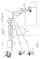
- FIG 3 schematically illustrates an overview of the communication possibilities of the remote diagnostic system of figure 1 .
- Local equipment at the robot 1 site is denoted 1 a, 11.
- the communications between the local site 2 equipment 1 a, 11 and the remote service center 3 equipment is referred to as 40 and is illustrated to be relayed via a communications network 41.
- the communications between the local site 2, when represented by the local technician 17 and the customer 16, and the remote service center 3 equipment 40 is exemplified as internet and denoted 42.
- Signal options between the local site 2 equipment and the remote service center equipment 40 via the communication network 41 are:
- a local service technician 17 sends or receives data via internet on line 50 of the figure.
- a customer 16 receives data via internet on line 51 of the figure.
- the data contains local site information (current or historic).
- the servers and databases included in the remote service center 3 can be structured in other ways.
- the current history database 12 and the historical database 13 may, of course be housed in one unit only, or divided into more than two units.
- the servers included in the remote service center 3 may, in the same way, be integrated into one unit or distributed into several separate units.
Description
- The present invention relates to a system of monitoring a plurality of robots spread at different locations at a remote service center by means of information exchange between individual robots and the remote service center.
- Common diagnostic systems for robot controllers consist of either a computational unit in the robot controller or diagnostics computations performed in a PC connected to the robot controller. Common to these existing solutions is the use of a high bandwidth of data signals that flow from the controller at the diagnostics computations. Diagnostics has conventionally been performed locally at the controller or at a device which has a high bandwidth connection to the controller.
-
US published application 2006/0206289 discloses a system of monitoring a plurality of robots from a remote location. The nature of the communication links used in said publication is not discussed. - Document
WO 02/095323 A - Document
US 2005/010311 A1 does not disclose any diagnostics engine for automatically performing qualitative diagnostic analysis on a system individual, such as an industrial robot. The means (the remote diagnostics system) provided in this document enables technical support personnel to diagnose problems. The data collection system (100) of this disclosure enables remote configuration, diagnostics and maintenance. Nothing is disclosed here that the system (100) is provided with diagnostics engines or tools for performing qualitative diagnostics for each individual. It is further mentioned in this document that the data collection system (100) provides a technician with all the information to diagnose a problem on-line and in real time, thus allowing the technician to resolve the problem without leaving the field service office. Accordingly, the system of this document does not disclose any means for automatically performing diagnostics on a robot connected to a remote center on a scheduled or event basis. - Still, a prior art document,
US 2003/023333 A1 , describes how diagnostics can be performed from a remote site. This document also does not describe any diagnostics automatically performed at any diagnostics tool or any diagnostics engine at a remote site. It is stated, for example, that: "...the homepages (17) offer the possibilities for an on-site diagnosis and also for remote diagnosis...." Nothing is mentioned about the robot itself automatically contacting a remote service center requesting diagnostics performed by a diagnostics engine provided at the remote service center. - If, in a robot monitoring system, a remote service center is established to perform the monitoring of a high number of robots spread at a plurality of plants at different geographic locations, an optimization of communication traffic between each individual robot of the system and the remote service center plays a major role to enable delivery of cost effective services (diagnostics) to a customer. One object of the present invention is to present a solution of a remote diagnostic system for delivery of remote diagnostics for robots with minimal communications costs. Another object of the invention is to present a solution of a remote diagnostic system for delivery of remote diagnostics for robots with a safe and high security of the communications between the individual robots and the remote service center.
- The present invention addresses problems in connection with communications and the localization of the computations in a remote diagnostic system for industrial robots. The present invention further addresses the issues directed to safety and security of the communications between a remote service center and industrial robots included in the system. One aspect of the invention is to provide each robot of the system with a service unit connected to the robot controller, wherein the service unit performs local diagnostic calculations and performs data compression. Said service unit is in turn connected to a remote connector server at a remote service center over a potentially low-bandwidth line or a line with high communication costs. The final or remaining diagnostics is performed at full computational power at said remote service center. Said remote service center further acts as a distribution point for information via a web browser and notification service, which allows e-mails and SMS-messages to be sent to the appropriate personnel at the robot site.
- Two key features of the invention are adaptiveness and flexibility in the system. To achieve this, the service units are, e.g., reprogrammable. Another important demand on the system is security.
- According to one aspect of the invention a system with the characteristics of the appended
claim 1 is presented. - According to a further aspect of the invention a method with the characteristics of the enclosed independent method claim is presented.
- Further aspects and embodiments of the invention are presented in the dependent claims.
- Locally in the system there is always at least one controller involved, normally close to an individual robot included in the system.
- The service unit is a communication and logging unit, which has different degrees of processing power depending upon the design. The service unit is connected to the controller of the individual robot. The term "service unit" is herein only used as a term of identification. The functions included in the so called "service unit" can be implemented as a logic unit connected to and integrated with the robot controller. Said functions can as well be implemented as logics included in the controller or as a mix of logics internally and externally of the robot controller locally at the robot.
- . A first task for the service unit is to verify the product (the industrial robot) that is connected and explicate its version. A second task for the service unit is to request and/or receive commands from the connector server at the remote service center with respect to what to do. A third task for the service box is to executes scripts and /or codes provided by the connector server. The service box will react on events, condition changes from the robot or on specific requests from a user of the remote service center.
- The connector server at the remote service center is provided with a code library storing codes for each specific service unit distributed across the remote diagnostic system. The connector server provides to the service unit codes/scripts on request from the service box or on demand from application performed at the connector server or from an end user.
- The communications infrastructure is responsible for transferring packets of information, in both directions, between the locally disposed robot, here called the local site, and the remote service center, here sometimes referred to as the remote site.
- An event scheme, wherein a service unit automatically requests diagnostic information from the remote service center, can be described as:
- 1° A service unit connects the connector server to request a code for operation.
- 2° The service unit gets access to a probe library at the connector server, which probes the robot controller with respect to such information as to version, performance etc. of the robot.
- 3° The service unit downloads a specific version of the code from a specific version library at the connector server for diagnostics and data gathering.
The communication between the service unit must be authorized and approved. - As communication between the local site and the remote site must be secure, there is presupposed that some form of an access point must be provided at both the local and the remotes sites. This access point can take the form of e.g. a VPN router or other piece of equipment allowing secure access to the remote service center.
- The solution according to the invention solves a problem with diagnostic activities at a remote site. Controller data is very awkward, as it is very processor intensive. Such data would be difficult to transfer in a cheap way to a remote site. One purpose with the service unit is to provide compression of controller data. Another purpose would be to perform packing of data. Other aspects regarding the service unit is that it should be non-intrusive, generic and reprogrammable. These aspects are important to achieve the adaptiveness and the flexibility of the remote diagnostic system, which provides services and diagnostics to a large and non homogeneous robot population (i.e. a large installed base of different products and versions of robots).
- As the controller data is compressed, possibly packaged and possibly preprocessed, cheap communication lines, such as internet or GPRS, can be used to arrive at a cost-effective system and thus enable the realization of the remote service center.
- The remote service center could be viewed as a Global service center and is a central hub for the system. This hub clearly comprises a web site and servers for the web site, as well as a database for customer information. Depending upon the local site communicating with the remote service center, the hub may have diagnostic tools for performing diagnostics of a robot at said local site and other tools for remotely connecting to a robot controller via the service unit at a local site.
- One object of the invention is to make it possible to provide robots without logics for monitoring purposes and in this way perform robots of a cheaper design. As the robot can communicate with the remote service center, monitoring tools, such as diagnostic units can be reached for performing said monitoring of the robot. In this way, the robot can get access to all monitoring and diagnostic tools available at the remote service center, wherein these tools are updated and of the latest design, which in turn make it unnecessary to provide the local robot controller with costly local diagnostic tools and a need of frequent robot software updates.
-
-
Fig. 1 is a basic schematic overview of the remote diagnostic system for robots according to one aspect of the invention. -
Fig. 2 shows a more detailed schematic overview of an embodiment of a remote diagnostic system according tofigure 1 . -
Fig. 3 is a schematic overview of communication possibilities in the remote diagnostic system offigure 1 . - Below the invention will be explained in greater detail by description of embodiments with reference to the accompanying drawings.
- The general architecture of the remote service center is structured to function as, among others, a central data storage with a web interface. A device logic layer will make the interface with customer equipment and will handle the communication between the servers and databases at the remote service center and the local site at the customer.
-
Fig. 1 shows a brief overview of the remote diagnostic system for robots according to one aspect of the invention and is explained more in detail in the following. Arobot 1 at a customer site, herein called alocal site 2, depicted in the system represents only one of the plurality of robots that can be included at the local site in the system. Thelocal site 2 further represents a plurality of local sites (at least two), which can be included in the remote diagnostic system. - In the system there is a robot services. Said robot services provide all the interfaces between the
local site 2 and theremote service center 3. The robot services hide all the complexity and specificity of the communication and transform robot specific data to generic data for a transfer of information between the local 2 andremote sites 3. - At the remote
service center site 3 the robot services is represented by a box denoted 4, which can be realized as a client server, here represented as aconnector server 4. The robot services, further, have one part at the local site (robot services client), herein referred to as a service unit and denoted 11, representing logics installed for the purpose, to handle the local process and events associated to therobot 1. Theservice unit 11 is connected to or integrated with therobot controller 1 a. Theconnector server 4 performs scheduled services, such as requesting data from alocal site 2 and reception of service data from alocal site 2. Crypting and encrypting data on communication with alocal site 2 is also implemented at theconnector server 4. Theconnector server 4 can be implemented on one or more connector servers at theremote server center 3. In the robot services, including theservice unit 11 and theconnector server 4, theconnector server 4 checks the authority of theservice unit 11 its access to theremote service center 3. Said access could, as an example, be implemented as a digital signature for theservice unit 11. - The
connector server 4 further stores a code archive/library, which is provided with the codes applicable for all theservice units 11 being authorized to access theconnector server 4 for exchange of data via thecommunication line 14a. This is arranged, such that when aspecific service unit 11 requests diagnostic information from theremote service center 3, theconnector server 4 identifies saidservice unit 11 and retrieves from the code library the code for use at thespecific service unit 11 and theconnector server 4, whereupon said retrieved code is downloaded to theservice unit 11. Theconnector server 4 can further be provided with software for pre-processing of data from theservice unit 11 and software for management of said data. If data from the service unit is delivered to theconnector server 4, theconnector server 4 will be provided with software for de-packing data packets. - In a
database layer 10 theremote service center 3 is further provided with acurrent history database 12, which contains all the information needed with respect to the requests of diagnostic information. The main information stored and managed are client user information (profile, site, robot type, robot variant, diagnostic date, contracts, mail etc.), communication information (local equipment, communication parameters, contracts, etc.) and administration information (security, rights, scripts, etc.). - The main purpose with the
configuration database 12 is to have it provided with all information needed to have monitoring and diagnostics working, excluding all information coming from therobot 1 itself or from a support engineer, when there is a contract between a supplier of the remote service center and a client (customer) using therobot 1. An administrator user has to be defined to manage and set up this client user information. - Further, a
historical database 13 is provided in thedatabase layer 10 at theremote service center 3. Thehistorical database 13 gathers all the information coming from therobot 1 system and other associated information from other actors and which needs to be kept for history or processing. The historical database can store customer related information, such as robot type, robot version, service performed, who the customer is, where the robot is situated, service program, etc. - The
remote service center 3 is provided with adiagnostics engine 6 equipped with processors and software for performing qualitative diagnostic analysis. Thediagnostics engine 6 has scheduled processes attached for generating diagnostics information based on raw material stored for thespecific robot 1 and on information sent from theservice unit 11 via thecommunication line 14a. Alarms may be generated based on the result of said scheduled diagnostic processes performed for said specific robot included in the system. An alarm depending on diagnostics can be sent to thecurrent history database 12 for storing and/or sent as an alert denoted byarrow 21. Thediagnostics engine 6 performs analyses, trendings and predictions regarding each robot of the system and stores knowledge and history regarding the robot. - A unit, herein called a business logic layer 7, contains business related logics for the company managing the
remote service center 2. The purpose of the business logic is to separate the database access and presentation logic from the user interface. The purpose is further to manage, for example, which services to be delivered, how the services is delivered to a customer (alarm, send or not by email/SMS, and to which person or addressee to send). - A presentation layer (web site) 8 is provided for allowing end users (service technicians at a remote service center console 24) at the
remote service center 3 to access, via a user interface on anetwork 14b at theremote service center 3, all information regarding the robot systems included in the remote service system as data per individual robot or per population of robots. Available robot system information includes data from the business logic layer 7, results achieved from raw data in thediagnostics engine 6, data from thedatabases remote service center 3 and direct data from theservice unit 11 orrobot controller 1 a.. - A
device layer 5 provides logic for theremote service center 3. Thisdevice logic layer 5 is the link between theconnector server 4, thecurrent history database 13, thehistory database 12, thediagnostics engine 6, the business logic layer 7 andpresentation layer 8 and comprises routines for data presentation and commands. Thisdevice logic layer 5 has knowledge implemented to it about therobots 1 of the system and a complete behavior of theremote service center 3. Thedevice logic layer 5 will also manage the scheduled operations of theservice center 3. - Still further, the
historical database 13 contains short term and long term information for current display, temporary processing or long term statistical information and reports. The historical database is scalable and managed professionally at theremote service center 3. - A more detailed description of an embodiment of the remote service center is illustrated in
figure 2 . - The
communication line 14a provides information in a dynamic way or through scheduled reports. Thecommunication line 14a is also used for all the configuration and administrative functions. Thecommunication line 14c is a communication channel for theend customer 16. By means of thecommunication line 14a it is also provided for access to therobots 1 in a secure way for theremote service center 3 to request information during events or on demand. Through thecommunication line 14a, theservice unit 11 can e. g. be reprogrammed. - The
remote service center 3 is further provided with aweb portal 14c making it possible forservice technicians 17 at thelocal site 2 to access theremote service center 3 and thus thedatabases - The user interface is managed by the
web portal 14c which is effected through a web client or a smart client. Thesame web portal 14c provides and manages information for different groups of users and must be secured. - In
figure 2 , theweb portal 14c is indicated at arrows, which points at a website presentation layer 8 at theremote service center 3. Theweb portal 14c access to the website presentation layer 8 from thelocal site 2, when an end user, such as a local user (customer) 16 or alocal technician 17 contacts theweb portal server 19, is protected by use of a firewall denoted by 18. The website presentation layer 8 handles, according to the example disclosed, the access fromservice technicians customer 16 throughweb portal server 19. Further, a customer web portal 18a is provided between the firewall 18 and theend users - Some tools are attached to the
web portal 14c to enhance the information displayed. These tools will be connected to raw data like logs or backups. - The
device logic layer 5 is the link between thehistorical database 13, thecurrent history database 12, the website presentation layer 8 comprising routines for data presentation and commands, and theconnector server 4. Thisdevice logic layer 5 has knowledge implemented to it about therobots 1 of the system and a complete behavior of theremote service center 3. Thedevice logic layer 5 will also manage the scheduled operations of theservice center 3. - The
connector server 4 further handles events and data to interface these data with the data of thehistorical database 13 and thepresentation layer 16 through thedevice logic layer 5. - Different alarms can be generated either by logics installed locally at the
robot 1 at thelocal site 2 or originating from diagnostics performed at theremote service center 3. These alarms are centrally managed in thedevice logic layer 5 for sending alarm on events, track the alarm states, etc., in dependence of the instructions implemented in the monitoring service set up for thespecific robot 1 installation. The alarm management service is implemented at thedevice logic layer 5, which can handle the alarm according to predetermined instructions. Adirect line 23 for an alert to the remote service technician at remoteservice center console 24 is also implemented. The diagnostics performed at thediagnostics engine 6 can also be arranged, in dependence on results of the performed diagnostics, to release analarm 23. - Diagnostic and service functions provided by
diagnostics engine 6 are implemented as tools available for processing at theremote service center 3, e.g. from thehistorical database 13 to supply theservice center 3 with qualitative diagnostic information and for performing advanced diagnostics and modeling. - Interactions performed at the remote diagnostic system for robots are illustrated in
figure 2 and discussed further below. Services provided by the system can, as an example, be classified in three usage modes. In the modes presented, aservice supplier center 30, preferably located at theremote service center 3, is pre-supposed. Saidservice supplier center 30 is provided with supplier personnel at a console for alerting personnel symbolized by the service technician at the servicesupplier center console 24, where said technician has access to all facilities of theremote service center 3 by means of console equipment, such as computers, displays, telephones, printers, faxes, etc. - In a first usage mode services are performed by the system when the
robot 1 is working and running normally at thelocal site 2 without any report of an error. In this mode, at least one of the following monitoring actions are performed in the system, wherein the system: - monitors service information to generate an event on a detected failure.
- gathers historical service information for future trouble shooting.
- gathers statistical service information for predictive maintenance.
- gathers usage information for reports.
- saves backup data on demand (from customer or event) for recovery.
- presents historical reports on the robot for the customer.
- In a second usage mode services, the
robot 1 has had a failure and theservice supplier center 30 as well as the customer has been informed. In this mode the system performs at least one of the actions: - provides information on the failure to the service supplier center,
- provides historical service information before and at the time of the failure,
- provides on request from the service supplier center information for performing diagnostics of the failure,
- provides the service supplier center with additional tools for analyzing the failure based on raw data received from the
robot 1. - provides the customer with information for display of current state of the
robot 1. - In a third usage mode services, the
robot 1 has experienced a major failure and cannot be recovered at thelocal site 2. In this third mode the system performs at least one of the actions: - informs the
service supplier center 30, whereupon this service supplier center requests direct connection to therobot 1, - the
service supplier center 30 performs advanced analysis of the robot utilizing advanced analysis tools, - the
service supplier center 30 assists thecustomer 17 in manual operations utilizing remote assistance tools, - the
service supplier center 30 will recover therobot 1 utilizing archived backup, - the
service supplier center 30 will recover therobot 1 system, utilizing recovering tools. - the
service supplier center 30 sets theservice unit 11 into pass-through allowing direct remote access to the controller's 1 a ports of a robot and then uses recovering tools and commands, - a
service unit 11 pass-through feature is used to deliver remotely advanced diagostics and optimisation methods/services by analysing further robot signals from thecontroller 1 a. - These modes are only examples and other modes of use of the system can be implemented.
-
Figure 3 schematically illustrates an overview of the communication possibilities of the remote diagnostic system offigure 1 . Local equipment at therobot 1 site is denoted 1 a, 11. The communications between thelocal site 2equipment remote service center 3 equipment is referred to as 40 and is illustrated to be relayed via acommunications network 41. The communications between thelocal site 2, when represented by thelocal technician 17 and thecustomer 16, and theremote service center 3equipment 40 is exemplified as internet and denoted 42. - The signal possibilities for a technician at the
suppliers service center 30 are illustrated in the figure as: - 43 operating diagnostic tools on raw data,
- 44 request available robot service information,
- 45 direct connection to
robot 1 for recovery, - 46 information reported from the system to the supplier's
service center 30 containing information on occurring events (failure, started or ongoing) including related information. - Signal options between the
local site 2 equipment and the remoteservice center equipment 40 via thecommunication network 41 are: - 47 communication in both directions via a communication line for providing direct secured access to
robot 1 from theremote service center 3. - 48 the
remote service center 3 requests data from therobot 1, - 49 the
remote service center 3 receives data from therobot 1. - A
local service technician 17 sends or receives data via internet online 50 of the figure. - A
customer 16 receives data via internet online 51 of the figure. The data contains local site information (current or historic). - The illustrated embodiment should only be referred to as an example. Thus, while there have been shown and described and pointed out fundamental novel features of the invention as applied to a preferred embodiment thereof, it will be understood that various omissions and substitutions and changes in the form and details of the devices illustrated, and in their operation, may be made by those skilled in the art without departing from the scope of the invention. For example, it is expressly stated here, that the servers and databases included in the
remote service center 3 can be structured in other ways. As examples, thecurrent history database 12 and thehistorical database 13 may, of course be housed in one unit only, or divided into more than two units. The servers included in theremote service center 3 may, in the same way, be integrated into one unit or distributed into several separate units.
Claims (27)
- A remote diagnostic system for at least two robots (1), wherein each robot is provided with a controller (1 a), and the system comprises a remote service center (3) provided with a diagnostic engine for performing diagnostics on the robots,- a plurality of service units (11) provided with local processing power, each of the service units connected to a respective one of the controllers and adapted to communication with the controller and the remote service center,- a connector server (4) provided at the remote service center, which stores a code library for communication management between the connector server and each of said service units (11), and- a communications infrastructure for a communication between said service units (11) and the connector server for transferring information for remote monitoring and diagnostics performed at the remote service center, andeach of said service units is capable to receive and execute code downloaded from the connector server at the remote site and to perform compression of data from the controller and to transfer compressed controller data to the remote service center.
- The remote diagnostic system according to claim 1, wherein said service unit (11) is provided with means for reacting on a request from said remote service center (3) or an event, such as a condition change of the robot (1) reported from the connected controller (1a), whereupon said means downloads from said connector server (4) a code or a script and for executing said code or script provided by said connector server (4).
- The remote diagnostic system according to claim 1 or 2, wherein said system comprises secure communication means utilizing secure access points at both the local site (2) and at the remote service center (3), such as a VPN router allowing secure access to the remote service center (3):
- The remote diagnostic system according to any of claims 1 to 3, wherein said service unit (11) comprises algorithms for compressing or packing data for enabling cost-effective communication between said service unit (11) and said remote service center (3).
- The remote diagnostic system according to claim 1, wherein said service unit (11) is provided with data measurement means and limited data diagnostics processing means for performing data measurements and diagnostics with respect to the robot (1) connected to the service unit (11).
- The remote diagnostic system according to claim 1, wherein said service unit (11) is a logic unit being implemented in a separately from the controller (1 a) situated device or implemented in a device integrated with the controller or implemented as logics included in the controller (1a) or as a mix of logics internally and externally of the controller (1a) of the robot (1).
- The remote diagnostic system according to claim 1, wherein said remote service center (3) serves as a hub of the remote diagnostic system and further includes:- a current history database (12) for storing information, such as client user information, communication information, administration information and current robot (1) data,- a historical database (13) for gathering historic and processing information of each specific robot (1) of the remote diagnostic system,- a communication line (14a) for communication between the service unit (11) and the remoter service center (3),- a presentation layer (8), and- a device logic layer (5) serving as a link between the connector server (4), the current history database (12), the historical database (13) and the presentation layer (8).
- The remote diagnostic system according to any of the preceding claims, wherein said remote service center (3) includes a suppliers service center (30) including a remote service center console (24) for a suppliers service technician browsing data of the remote service center (3).
- The remote diagnostic system according to claim 7, wherein an alarm management service is linked to device logic layer (5) and/or to said diagnostics engine (6) and/or business logic layer (7) for initiating an alarm upon predetermined instructions and/or results from said performed diagnostics.
- The remote diagnostic system according to claim 7, wherein said diagnostics engine (6) is provided with diagnostic tools for performing diagnostics on at least one of:- data stored in said historical database (13) according to scheduled routines,- data stored in said current history database (12) according to scheduled routines,- data stored in said historical database (13) on request from the service unit (11),- data stored in said current history database (12) on request from the service unit (11).
- The remote diagnostic system according to claim 8, wherein said diagnostics engine (6) is provided with diagnostic tools for performing diagnostics on at least one of:- data stored in said historical database (13) on request from the remote service center console (24),- data stored in said current history database (12) on request from the remote service center console (24),
- The remote diagnostic system according to claim 7, wherein the current history database (12) has information storing means for storing data including administration data on the monitor of the robots (1) in relation to a customer (16).
- The remote diagnostic system according to claim 7, wherein the historical database (13) has raw data collecting means for collecting raw data for the specific robot (1) to be used for generating diagnostics in said diagnostics engine (6).
- The remote diagnostic system according to claim 7 or 13, wherein the historical database (13) has storing means for storing short term and long term data for current display or temporary processing or long term statistical information and reports for the specific robot (1).
- The remote diagnostic system according to claim 5, wherein a service technician (17) at the local site (2) and/or a customer (16) at the local site (2) has communication access to the layer device/logic (5) via the web portal (14c) and a user interface.
- The remote diagnostic system according to claim 15, wherein the web portal (14c) is effected through a web client or a smart client which is included in the presentation layer (8).
- The remote diagnostic system according to claim 15, wherein the web portal (14c) is implemented in a web server (19) provided with a firewall (18).
- The remote diagnostic system according to claim 7, wherein the device logic layer (5) is provided with routines for managing scheduled routines of the remote service center (3).
- The remote diagnostic system according to claim 18, wherein the device logic layer (5) has means provided with information regarding robots (1) connected to the system and a complete knowledge of the configuration of the remote service center (3).
- The remote diagnostic system according to claim 7, wherein the connector server (4) has means for handling events and data for a specific robot (1) for interfacing said events and data with the historical data associated with the specific robot (1) stored in the historical database (13).
- The remote diagnostic system according to any of the preceding claims, wherein the connector server (4) has a list of signatures, each said signature identifying a service unit (11) being authorized to access said remote service center (3).
- The remote diagnostic system according to claim 1 or 7, wherein said service unit (11) has means for passing telnet, ftp, and other protocol connections directly from the connector server (4), or other units, in the remote service center to communication ports on the robot controller (1a).
- A method for remotely performing diagnostic analysis of robots, utilizing the remote diagnostic system of claim 1, wherein said service unit (11) on request from the remote service center (3) or initiated by a condition change at the robot (1) connected to the service unit performs at least one of the steps from the group of:- verifying to said remote service center (3) data of the connected robot (1) individual, such as type, model, serial number, variant;- requesting from the remote service center (3) a code or a script for execution at the service unit (11),- transferring to the remote service center (3) a signature for getting access to the remote service center (3),- checking the authorization of a code or script received from the remote service center (3).
- The method according to claim 23, wherein in a first usage mode when a monitored robot (1) works normally, the system performs diagnostics according to any one of the steps from the group of:- monitoring service information to generate an event on a detected failure,- gathering historical service information for future trouble shooting,- gathering statistical service information for predictive maintenance,- gathering usage information for reports,- saving backup data on demand (from customer or event) for recovery,- presenting historical reports on the robot for the customer.
- The method according to claim 23, wherein in second usage mode applied when the robot (1) has experienced a failure, the system performs diagnostics according to any one of the steps from the group of:- providing information on the failure to the service supplier center,- providing historical service information before and at the time of the failure,- providing on request from the service supplier center (30) information for performing diagnostics of the failure,- providing the service supplier center (30) with additional tools for analyzing the failure based on raw data received from the robot (1),- providing the customer (16) with information for display of current state of the robot (1.)
- The method according to claim 23 or 24, wherein in a third usage mode applied when the robot (1) has experienced a major failure and cannot be recovered at the local site (2), the system performs diagnostics according to any one of the steps from the group of:- informing the service supplier center (30), whereupon this service supplier center requests direct connection to the robot (1) via the service unit (11),- the service supplier center (30) performs advanced analysis of the robot (1) utilizing advanced analysis tools,- the service supplier center (30) assists the customer (16) and/or a local service technician (17) in manual operations utilizing remote assistance tools,- the service supplier center (30) recovers the robot (1) utilizing archived backup,- the service supplier center (30) recovers the robot (1) system, utilizing recovering tools,- the service supplier center (30) sets the service unit 11 into pass-through allowing direct remote access to the controller's (1a) ports of a robot and then uses recovering tools and commands,- a service unit (11) pass-through feature is used to deliver remotely advanced diagnostics and optimization methods/services by further analyzing robot signals transferred directly from the controller (1a).
- The method according to any of claims 23 to 26 including the step of:- programming said service unit (11) from said remote service center (3).
Priority Applications (3)
| Application Number | Priority Date | Filing Date | Title |
|---|---|---|---|
| EP07102279.2A EP1958738B1 (en) | 2007-02-13 | 2007-02-13 | Remote diagnostic system for robots |
| US12/068,922 US8121729B2 (en) | 2007-02-13 | 2008-02-13 | Remote diagnostic system for robots |
| CNA2008101092965A CN101286954A (en) | 2007-02-13 | 2008-02-13 | Remote diagnostic system for robots |
Applications Claiming Priority (1)
| Application Number | Priority Date | Filing Date | Title |
|---|---|---|---|
| EP07102279.2A EP1958738B1 (en) | 2007-02-13 | 2007-02-13 | Remote diagnostic system for robots |
Publications (2)
| Publication Number | Publication Date |
|---|---|
| EP1958738A1 EP1958738A1 (en) | 2008-08-20 |
| EP1958738B1 true EP1958738B1 (en) | 2013-08-14 |
Family
ID=38181210
Family Applications (1)
| Application Number | Title | Priority Date | Filing Date |
|---|---|---|---|
| EP07102279.2A Active EP1958738B1 (en) | 2007-02-13 | 2007-02-13 | Remote diagnostic system for robots |
Country Status (3)
| Country | Link |
|---|---|
| US (1) | US8121729B2 (en) |
| EP (1) | EP1958738B1 (en) |
| CN (1) | CN101286954A (en) |
Cited By (2)
| Publication number | Priority date | Publication date | Assignee | Title |
|---|---|---|---|---|
| CN105095817A (en) * | 2015-07-03 | 2015-11-25 | 百度在线网络技术(北京)有限公司 | Intelligent robot fault diagnosis method based on artificial intelligence, device and system |
| CN105578132A (en) * | 2015-12-14 | 2016-05-11 | 西安科技大学 | Belt conveyer remote video maintenance auxiliary diagnosis system |
Families Citing this family (57)
| Publication number | Priority date | Publication date | Assignee | Title |
|---|---|---|---|---|
| EP1958738B1 (en) * | 2007-02-13 | 2013-08-14 | Abb Research Ltd. | Remote diagnostic system for robots |
| EP2082851A1 (en) | 2008-05-16 | 2009-07-29 | ABB Research Ltd. | An industrial robot capable of supervising its environmental impact and a method thereof |
| WO2010058241A1 (en) * | 2008-11-24 | 2010-05-27 | Abb Research Ltd. | A system and a method for providing control and automation services |
| US20100168914A1 (en) * | 2008-12-29 | 2010-07-01 | Electronics And Telecommunications Research Institute | Diagnosis and management server for multi-kinds robots |
| WO2011150373A1 (en) | 2010-05-28 | 2011-12-01 | Black Swan Solar, Inc. | Heliostat repositioning system and method |
| CN102087759B (en) * | 2010-12-03 | 2013-01-09 | 重庆理工大学 | Traceable medical communication service robot |
| US8442790B2 (en) | 2010-12-03 | 2013-05-14 | Qbotix, Inc. | Robotic heliostat calibration system and method |
| CN102063111A (en) * | 2010-12-14 | 2011-05-18 | 广东雅达电子股份有限公司 | Mobile terminal-based remote robot control system |
| DE102011010505A1 (en) * | 2011-02-07 | 2012-08-09 | Dürr Systems GmbH | Adaptation of the dynamics of at least one robot |
| US9862051B2 (en) | 2011-09-27 | 2018-01-09 | Illinois Tool Works Inc. | Welding system and method utilizing cloud computing and data storage |
| US8965580B2 (en) | 2012-06-21 | 2015-02-24 | Rethink Robotics, Inc. | Training and operating industrial robots |
| CN109213123A (en) * | 2012-07-26 | 2019-01-15 | 苏州宝时得电动工具有限公司 | The control method and robot system of robot |
| US9579806B2 (en) | 2012-08-23 | 2017-02-28 | Rethink Robotics, Inc. | Robotic power and signal distribution using laminated cable with separator webs |
| CN103679837B (en) | 2012-09-07 | 2018-05-18 | 发纳科机器人美国公司 | Monitoring/analysis robot relevant information is simultaneously shown in the system on intelligent apparatus |
| WO2014044311A1 (en) | 2012-09-20 | 2014-03-27 | Abb Technology Ltd | Overall equipment effectiveness of a robot cell |
| US9929944B2 (en) | 2012-11-07 | 2018-03-27 | Abb Schweiz Ag | Redundancy device unit and method for determining fault in industrial control system, industrial control system and industrial system comprising redundancy device unit |
| AU2013204965B2 (en) | 2012-11-12 | 2016-07-28 | C2 Systems Limited | A system, method, computer program and data signal for the registration, monitoring and control of machines and devices |
| CN103020780B (en) * | 2012-12-21 | 2015-10-28 | 常州大学 | A kind of special equipment detects and Maintenance Management System and method thereof |
| US9665093B2 (en) | 2013-03-15 | 2017-05-30 | Illinois Tool Works Inc. | Welding resource performance comparison system and method |
| US9684303B2 (en) | 2013-03-15 | 2017-06-20 | Illinois Tool Works Inc. | Welding resource tracking and analysis system and method |
| US10012962B2 (en) | 2013-03-15 | 2018-07-03 | Illinois Tool Works Inc. | Welding resource performance goal system and method |
| US9704140B2 (en) | 2013-07-03 | 2017-07-11 | Illinois Tool Works Inc. | Welding system parameter comparison system and method |
| US10558953B2 (en) | 2013-07-03 | 2020-02-11 | Illinois Tool Works Inc. | Welding system parameter comparison system and method |
| DE102013216421A1 (en) * | 2013-08-20 | 2015-03-12 | Robert Bosch Gmbh | Control system for controlling at least one welding process |
| US11103948B2 (en) | 2014-08-18 | 2021-08-31 | Illinois Tool Works Inc. | Systems and methods for a personally allocated interface for use in a welding system |
| US10242317B2 (en) | 2014-11-25 | 2019-03-26 | Illinois Tool Works Inc. | System for estimating the amount and content of fumes |
| US10616080B2 (en) | 2014-11-26 | 2020-04-07 | Fanuc America Corporation | System for diagnosis of robot state |
| CN104656612A (en) * | 2014-12-29 | 2015-05-27 | 四川双众科技有限公司 | Running status remote detection system for reactive compensation device |
| US9486921B1 (en) * | 2015-03-26 | 2016-11-08 | Google Inc. | Methods and systems for distributing remote assistance to facilitate robotic object manipulation |
| CN104767831A (en) * | 2015-04-30 | 2015-07-08 | 韦勇 | B/S framework vehicle management service system |
| US20190381665A1 (en) * | 2015-05-08 | 2019-12-19 | C2 Systems Limited | System, method, computer program and data signal for the registration, monitoring and control of machines and devices |
| US20160337203A1 (en) | 2015-05-11 | 2016-11-17 | Honeywell International Inc. | System and approach for remote room controller and device diagnostics and health monitoring |
| US10031495B2 (en) * | 2015-05-29 | 2018-07-24 | Rockwell Automation Technologies, Inc. | Data collection for assistance in an industrial automation environment |
| JP6862081B2 (en) * | 2015-06-23 | 2021-04-21 | キヤノン株式会社 | Robot system control methods, control programs, computer-readable recording media, and robot systems |
| CN104991497A (en) * | 2015-07-09 | 2015-10-21 | 安徽埃夫特智能装备有限公司 | Industrial robot remote service and monitoring system |
| CN105159252A (en) * | 2015-08-18 | 2015-12-16 | 深圳市科昭科技有限公司 | Robot intelligent cloud compatible control system |
| US9751211B1 (en) * | 2015-10-08 | 2017-09-05 | Google Inc. | Smart robot part |
| CN105426986B (en) * | 2015-10-30 | 2019-06-21 | 上海交通大学 | High-reliability Control method and system in multi-robot system |
| JP6625421B2 (en) * | 2015-12-11 | 2019-12-25 | シスメックス株式会社 | Medical robot system, data analysis device, and medical robot monitoring method |
| EP3182134A1 (en) * | 2015-12-18 | 2017-06-21 | Roche Diagnostics GmbH | Method for restoring settings of an instrument for processing a sample or a reagent, and system comprising an instrument for processing a sample or reagent |
| US11131978B2 (en) | 2015-12-28 | 2021-09-28 | Illinois Tool Works Inc. | Systems and methods for analyzing manufacturing parameters |
| EP3239792A1 (en) * | 2016-04-29 | 2017-11-01 | Robotics Club Limited | Server based robotic system and a method for operating the robotic system |
| RU2625209C1 (en) * | 2016-05-13 | 2017-07-12 | Акционерное общество "Российская корпорация ракетно-космического приборостроения и информационных систем" (АО "Российские космические системы") | System and method for remote equipment control |
| CN105843202A (en) * | 2016-05-30 | 2016-08-10 | 湖北骐通智能科技股份有限公司 | Industrial robot control system and operation mode switching method thereof |
| JP6581050B2 (en) * | 2016-08-24 | 2019-09-25 | 川崎重工業株式会社 | Robot remote monitoring system |
| EP4116984A1 (en) | 2016-08-29 | 2023-01-11 | Beckman Coulter, Inc. | Remote data analysis and diagnosis |
| CN106572192A (en) * | 2016-11-16 | 2017-04-19 | 苏州宝维网络有限公司 | Maintenance software based processing system |
| CN106406289A (en) * | 2016-11-17 | 2017-02-15 | 北京中科汇联科技股份有限公司 | Robot troubleshooting system and method |
| CN107330253B (en) * | 2017-06-15 | 2020-09-08 | 重庆柚瓣家科技有限公司 | Method for realizing remote grading diagnosis and treatment by robot |
| US10761542B1 (en) | 2017-07-11 | 2020-09-01 | Waymo Llc | Methods and systems for keeping remote assistance operators alert |
| CN111203869B (en) * | 2018-11-21 | 2021-12-17 | 深圳市优必选科技有限公司 | Robot system maintenance method and device, robot and readable storage medium |
| EP3902658A4 (en) * | 2018-12-24 | 2022-10-19 | ABB Schweiz AG | Method for diagnosing a robot, device and server |
| US11311958B1 (en) * | 2019-05-13 | 2022-04-26 | Airgas, Inc. | Digital welding and cutting efficiency analysis, process evaluation and response feedback system for process optimization |
| US11850756B2 (en) * | 2020-06-30 | 2023-12-26 | WaferPath, Inc. | Robot monitoring and error detection system |
| CN111768860A (en) * | 2020-08-11 | 2020-10-13 | 徐航 | Method for realizing in-situ hospitalization of user by using telemedicine robot system |
| CN116348254A (en) * | 2020-10-05 | 2023-06-27 | Abb瑞士股份有限公司 | Method for enabling an industrial collector to transmit telemetry data to a plurality of consumers |
| CN113070906B (en) * | 2021-04-07 | 2022-04-26 | 北京云迹科技股份有限公司 | Service robot system and network fault diagnosis method and device thereof |
Family Cites Families (19)
| Publication number | Priority date | Publication date | Assignee | Title |
|---|---|---|---|---|
| US6058307A (en) * | 1995-11-30 | 2000-05-02 | Amsc Subsidiary Corporation | Priority and preemption service system for satellite related communication using central controller |
| US6259969B1 (en) * | 1997-06-04 | 2001-07-10 | Nativeminds, Inc. | System and method for automatically verifying the performance of a virtual robot |
| US6732191B1 (en) * | 1997-09-10 | 2004-05-04 | Schneider Automation Inc. | Web interface to an input/output device |
| US20010032278A1 (en) * | 1997-10-07 | 2001-10-18 | Brown Stephen J. | Remote generation and distribution of command programs for programmable devices |
| US6317788B1 (en) * | 1998-10-30 | 2001-11-13 | Hewlett-Packard Company | Robot policies for monitoring availability and response of network performance as seen from user perspective |
| US8044793B2 (en) * | 2001-03-01 | 2011-10-25 | Fisher-Rosemount Systems, Inc. | Integrated device alerts in a process control system |
| US6446192B1 (en) * | 1999-06-04 | 2002-09-03 | Embrace Networks, Inc. | Remote monitoring and control of equipment over computer networks using a single web interfacing chip |
| US6518980B1 (en) * | 1999-11-19 | 2003-02-11 | Fanuc Robotics North America, Inc. | Method and system for allowing a programmable controller to communicate with a remote computer |
| JP2001150374A (en) * | 1999-11-25 | 2001-06-05 | Sony Corp | Failure diagnostic system for robot |
| JP2001222316A (en) * | 2000-02-09 | 2001-08-17 | Sony Corp | System and method for managing robot |
| DE20004370U1 (en) | 2000-03-10 | 2001-07-19 | Kuka Schweissanlagen Gmbh | Industrial production plant with WEB control system |
| JP2002049414A (en) * | 2000-05-26 | 2002-02-15 | Yutaka Electronics Industry Co Ltd | Maintenance method for industrial machine and system for the same |
| JP4739556B2 (en) * | 2001-03-27 | 2011-08-03 | 株式会社安川電機 | Remote adjustment and abnormality judgment device for control target |
| US6795778B2 (en) * | 2001-05-24 | 2004-09-21 | Lincoln Global, Inc. | System and method for facilitating welding system diagnostics |
| US7130769B1 (en) * | 2002-01-30 | 2006-10-31 | Advanced Micro Devices, Inc. | Method of dynamically designing a preventative maintenance schedule based upon sensor data, and system for accomplishing same |
| US6901306B2 (en) * | 2002-02-27 | 2005-05-31 | Hitachi High-Technologies Corporation | Semiconductor manufacturing apparatus and its diagnosis apparatus and operating system |
| WO2004102295A2 (en) | 2003-05-12 | 2004-11-25 | Abb Inc. | Asset life cycle management method and apparatus |
| US20050010311A1 (en) | 2003-07-10 | 2005-01-13 | Barbazette Christopher J. | Data collection and diagnostic system for a semiconductor fabrication facility |
| EP1958738B1 (en) * | 2007-02-13 | 2013-08-14 | Abb Research Ltd. | Remote diagnostic system for robots |
-
2007
- 2007-02-13 EP EP07102279.2A patent/EP1958738B1/en active Active
-
2008
- 2008-02-13 CN CNA2008101092965A patent/CN101286954A/en active Pending
- 2008-02-13 US US12/068,922 patent/US8121729B2/en active Active
Cited By (3)
| Publication number | Priority date | Publication date | Assignee | Title |
|---|---|---|---|---|
| CN105095817A (en) * | 2015-07-03 | 2015-11-25 | 百度在线网络技术(北京)有限公司 | Intelligent robot fault diagnosis method based on artificial intelligence, device and system |
| CN105095817B (en) * | 2015-07-03 | 2018-03-09 | 百度在线网络技术(北京)有限公司 | Intelligent robot method for diagnosing faults, apparatus and system based on artificial intelligence |
| CN105578132A (en) * | 2015-12-14 | 2016-05-11 | 西安科技大学 | Belt conveyer remote video maintenance auxiliary diagnosis system |
Also Published As
| Publication number | Publication date |
|---|---|
| EP1958738A1 (en) | 2008-08-20 |
| US8121729B2 (en) | 2012-02-21 |
| CN101286954A (en) | 2008-10-15 |
| US20080247549A1 (en) | 2008-10-09 |
Similar Documents
| Publication | Publication Date | Title |
|---|---|---|
| EP1958738B1 (en) | Remote diagnostic system for robots | |
| CN107026894B (en) | Apparatus and method for automatic notification through industrial asset delivery | |
| CN113112086B (en) | Intelligent production system based on edge calculation and identification analysis | |
| US7953842B2 (en) | Open network-based data acquisition, aggregation and optimization for use with process control systems | |
| CN109690692B (en) | Method for remotely performing comprehensive online monitoring on nuclear power station and comprehensive online monitoring system | |
| JP5503875B2 (en) | Process control system and process control method | |
| US6795799B2 (en) | Remote diagnosis server | |
| US9400867B2 (en) | Method and system for monitoring and reporting equipment operating conditions and diagnostic information | |
| US7103427B2 (en) | Delivery of process plant notifications | |
| US20180006913A1 (en) | Industrial internet of things data pipeline for a data lake | |
| US20130211546A1 (en) | Smart device for industrial automation | |
| CN109857020A (en) | Novel maintenance management system | |
| KR20140130543A (en) | Method and system for condition monitoring of a group of plants | |
| CN104954242A (en) | Unified data ingestion adapter for migration of industrial data to a cloud platform | |
| CN107921981A (en) | The monitoring and control of distributed machines | |
| US20130282333A1 (en) | Service port explorer | |
| US20200058173A1 (en) | System and method for remote diagnostics and monitoring of heavy equipment | |
| US20180130339A1 (en) | System & methods for critical infrastructure automation | |
| KR20140045367A (en) | System for recommending helicopter engine maintenance | |
| CN213302804U (en) | Textile machinery equipment thing networking monitored control system | |
| KR20200084424A (en) | Industrial IoT system | |
| Kirubashankar et al. | Remote monitoring system for distributed control of industrial plant process | |
| US10255797B1 (en) | Integrated alarm management system (ALMS) KPIs with plant information system | |
| KR20180137826A (en) | System for monitoring sensor status based on CoAP |
Legal Events
| Date | Code | Title | Description |
|---|---|---|---|
| PUAI | Public reference made under article 153(3) epc to a published international application that has entered the european phase |
Free format text: ORIGINAL CODE: 0009012 |
|
| 17P | Request for examination filed |
Effective date: 20080306 |
|
| AK | Designated contracting states |
Kind code of ref document: A1 Designated state(s): AT BE BG CH CY CZ DE DK EE ES FI FR GB GR HU IE IS IT LI LT LU LV MC NL PL PT RO SE SI SK TR |
|
| AX | Request for extension of the european patent |
Extension state: AL BA HR MK RS |
|
| AKX | Designation fees paid |
Designated state(s): AT BE BG CH CY CZ DE DK EE ES FI FR GB GR HU IE IS IT LI LT LU LV MC NL PL PT RO SE SI SK TR |
|
| 17Q | First examination report despatched |
Effective date: 20120220 |
|
| GRAP | Despatch of communication of intention to grant a patent |
Free format text: ORIGINAL CODE: EPIDOSNIGR1 |
|
| INTG | Intention to grant announced |
Effective date: 20130424 |
|
| GRAS | Grant fee paid |
Free format text: ORIGINAL CODE: EPIDOSNIGR3 |
|
| GRAA | (expected) grant |
Free format text: ORIGINAL CODE: 0009210 |
|
| RIN1 | Information on inventor provided before grant (corrected) |
Inventor name: MURPHY, STEVE Inventor name: BLANC, DOMINIQUE Inventor name: EKELUND, ANDERS Inventor name: NYMARK, JESSICA Inventor name: ALT, JEAN-CHRISTOPHE |
|
| AK | Designated contracting states |
Kind code of ref document: B1 Designated state(s): AT BE BG CH CY CZ DE DK EE ES FI FR GB GR HU IE IS IT LI LT LU LV MC NL PL PT RO SE SI SK TR |
|
| REG | Reference to a national code |
Ref country code: GB Ref legal event code: FG4D |
|
| REG | Reference to a national code |
Ref country code: CH Ref legal event code: EP Ref country code: AT Ref legal event code: REF Ref document number: 626515 Country of ref document: AT Kind code of ref document: T Effective date: 20130815 |
|
| REG | Reference to a national code |
Ref country code: IE Ref legal event code: FG4D |
|
| REG | Reference to a national code |
Ref country code: DE Ref legal event code: R096 Ref document number: 602007032191 Country of ref document: DE Effective date: 20131010 |
|
| REG | Reference to a national code |
Ref country code: AT Ref legal event code: MK05 Ref document number: 626515 Country of ref document: AT Kind code of ref document: T Effective date: 20130814 Ref country code: NL Ref legal event code: VDEP Effective date: 20130814 |
|
| REG | Reference to a national code |
Ref country code: LT Ref legal event code: MG4D |
|
| PG25 | Lapsed in a contracting state [announced via postgrant information from national office to epo] |
Ref country code: CY Free format text: LAPSE BECAUSE OF FAILURE TO SUBMIT A TRANSLATION OF THE DESCRIPTION OR TO PAY THE FEE WITHIN THE PRESCRIBED TIME-LIMIT Effective date: 20130626 Ref country code: SE Free format text: LAPSE BECAUSE OF FAILURE TO SUBMIT A TRANSLATION OF THE DESCRIPTION OR TO PAY THE FEE WITHIN THE PRESCRIBED TIME-LIMIT Effective date: 20130814 Ref country code: AT Free format text: LAPSE BECAUSE OF FAILURE TO SUBMIT A TRANSLATION OF THE DESCRIPTION OR TO PAY THE FEE WITHIN THE PRESCRIBED TIME-LIMIT Effective date: 20130814 Ref country code: LT Free format text: LAPSE BECAUSE OF FAILURE TO SUBMIT A TRANSLATION OF THE DESCRIPTION OR TO PAY THE FEE WITHIN THE PRESCRIBED TIME-LIMIT Effective date: 20130814 Ref country code: PT Free format text: LAPSE BECAUSE OF FAILURE TO SUBMIT A TRANSLATION OF THE DESCRIPTION OR TO PAY THE FEE WITHIN THE PRESCRIBED TIME-LIMIT Effective date: 20131216 Ref country code: IS Free format text: LAPSE BECAUSE OF FAILURE TO SUBMIT A TRANSLATION OF THE DESCRIPTION OR TO PAY THE FEE WITHIN THE PRESCRIBED TIME-LIMIT Effective date: 20131214 |
|
| PG25 | Lapsed in a contracting state [announced via postgrant information from national office to epo] |
Ref country code: FI Free format text: LAPSE BECAUSE OF FAILURE TO SUBMIT A TRANSLATION OF THE DESCRIPTION OR TO PAY THE FEE WITHIN THE PRESCRIBED TIME-LIMIT Effective date: 20130814 Ref country code: BE Free format text: LAPSE BECAUSE OF FAILURE TO SUBMIT A TRANSLATION OF THE DESCRIPTION OR TO PAY THE FEE WITHIN THE PRESCRIBED TIME-LIMIT Effective date: 20130814 Ref country code: GR Free format text: LAPSE BECAUSE OF FAILURE TO SUBMIT A TRANSLATION OF THE DESCRIPTION OR TO PAY THE FEE WITHIN THE PRESCRIBED TIME-LIMIT Effective date: 20131115 Ref country code: SI Free format text: LAPSE BECAUSE OF FAILURE TO SUBMIT A TRANSLATION OF THE DESCRIPTION OR TO PAY THE FEE WITHIN THE PRESCRIBED TIME-LIMIT Effective date: 20130814 Ref country code: PL Free format text: LAPSE BECAUSE OF FAILURE TO SUBMIT A TRANSLATION OF THE DESCRIPTION OR TO PAY THE FEE WITHIN THE PRESCRIBED TIME-LIMIT Effective date: 20130814 Ref country code: LV Free format text: LAPSE BECAUSE OF FAILURE TO SUBMIT A TRANSLATION OF THE DESCRIPTION OR TO PAY THE FEE WITHIN THE PRESCRIBED TIME-LIMIT Effective date: 20130814 |
|
| PG25 | Lapsed in a contracting state [announced via postgrant information from national office to epo] |
Ref country code: CY Free format text: LAPSE BECAUSE OF FAILURE TO SUBMIT A TRANSLATION OF THE DESCRIPTION OR TO PAY THE FEE WITHIN THE PRESCRIBED TIME-LIMIT Effective date: 20130814 |
|
| PG25 | Lapsed in a contracting state [announced via postgrant information from national office to epo] |
Ref country code: CZ Free format text: LAPSE BECAUSE OF FAILURE TO SUBMIT A TRANSLATION OF THE DESCRIPTION OR TO PAY THE FEE WITHIN THE PRESCRIBED TIME-LIMIT Effective date: 20130814 Ref country code: SK Free format text: LAPSE BECAUSE OF FAILURE TO SUBMIT A TRANSLATION OF THE DESCRIPTION OR TO PAY THE FEE WITHIN THE PRESCRIBED TIME-LIMIT Effective date: 20130814 Ref country code: DK Free format text: LAPSE BECAUSE OF FAILURE TO SUBMIT A TRANSLATION OF THE DESCRIPTION OR TO PAY THE FEE WITHIN THE PRESCRIBED TIME-LIMIT Effective date: 20130814 Ref country code: RO Free format text: LAPSE BECAUSE OF FAILURE TO SUBMIT A TRANSLATION OF THE DESCRIPTION OR TO PAY THE FEE WITHIN THE PRESCRIBED TIME-LIMIT Effective date: 20130814 Ref country code: NL Free format text: LAPSE BECAUSE OF FAILURE TO SUBMIT A TRANSLATION OF THE DESCRIPTION OR TO PAY THE FEE WITHIN THE PRESCRIBED TIME-LIMIT Effective date: 20130814 Ref country code: EE Free format text: LAPSE BECAUSE OF FAILURE TO SUBMIT A TRANSLATION OF THE DESCRIPTION OR TO PAY THE FEE WITHIN THE PRESCRIBED TIME-LIMIT Effective date: 20130814 |
|
| PG25 | Lapsed in a contracting state [announced via postgrant information from national office to epo] |
Ref country code: ES Free format text: LAPSE BECAUSE OF FAILURE TO SUBMIT A TRANSLATION OF THE DESCRIPTION OR TO PAY THE FEE WITHIN THE PRESCRIBED TIME-LIMIT Effective date: 20130814 Ref country code: IT Free format text: LAPSE BECAUSE OF FAILURE TO SUBMIT A TRANSLATION OF THE DESCRIPTION OR TO PAY THE FEE WITHIN THE PRESCRIBED TIME-LIMIT Effective date: 20130814 |
|
| PLBE | No opposition filed within time limit |
Free format text: ORIGINAL CODE: 0009261 |
|
| STAA | Information on the status of an ep patent application or granted ep patent |
Free format text: STATUS: NO OPPOSITION FILED WITHIN TIME LIMIT |
|
| 26N | No opposition filed |
Effective date: 20140515 |
|
| REG | Reference to a national code |
Ref country code: DE Ref legal event code: R097 Ref document number: 602007032191 Country of ref document: DE Effective date: 20140515 |
|
| PG25 | Lapsed in a contracting state [announced via postgrant information from national office to epo] |
Ref country code: MC Free format text: LAPSE BECAUSE OF FAILURE TO SUBMIT A TRANSLATION OF THE DESCRIPTION OR TO PAY THE FEE WITHIN THE PRESCRIBED TIME-LIMIT Effective date: 20130814 Ref country code: LU Free format text: LAPSE BECAUSE OF FAILURE TO SUBMIT A TRANSLATION OF THE DESCRIPTION OR TO PAY THE FEE WITHIN THE PRESCRIBED TIME-LIMIT Effective date: 20140213 |
|
| REG | Reference to a national code |
Ref country code: CH Ref legal event code: PL |
|
| PG25 | Lapsed in a contracting state [announced via postgrant information from national office to epo] |
Ref country code: LI Free format text: LAPSE BECAUSE OF NON-PAYMENT OF DUE FEES Effective date: 20140228 Ref country code: CH Free format text: LAPSE BECAUSE OF NON-PAYMENT OF DUE FEES Effective date: 20140228 |
|
| REG | Reference to a national code |
Ref country code: IE Ref legal event code: MM4A |
|
| PG25 | Lapsed in a contracting state [announced via postgrant information from national office to epo] |
Ref country code: IE Free format text: LAPSE BECAUSE OF NON-PAYMENT OF DUE FEES Effective date: 20140213 |
|
| REG | Reference to a national code |
Ref country code: FR Ref legal event code: PLFP Year of fee payment: 10 |
|
| PG25 | Lapsed in a contracting state [announced via postgrant information from national office to epo] |
Ref country code: BG Free format text: LAPSE BECAUSE OF FAILURE TO SUBMIT A TRANSLATION OF THE DESCRIPTION OR TO PAY THE FEE WITHIN THE PRESCRIBED TIME-LIMIT Effective date: 20130814 |
|
| PG25 | Lapsed in a contracting state [announced via postgrant information from national office to epo] |
Ref country code: TR Free format text: LAPSE BECAUSE OF FAILURE TO SUBMIT A TRANSLATION OF THE DESCRIPTION OR TO PAY THE FEE WITHIN THE PRESCRIBED TIME-LIMIT Effective date: 20130814 Ref country code: HU Free format text: LAPSE BECAUSE OF FAILURE TO SUBMIT A TRANSLATION OF THE DESCRIPTION OR TO PAY THE FEE WITHIN THE PRESCRIBED TIME-LIMIT; INVALID AB INITIO Effective date: 20070213 |
|
| REG | Reference to a national code |
Ref country code: FR Ref legal event code: PLFP Year of fee payment: 11 |
|
| REG | Reference to a national code |
Ref country code: FR Ref legal event code: PLFP Year of fee payment: 12 |
|
| REG | Reference to a national code |
Ref country code: DE Ref legal event code: R081 Ref document number: 602007032191 Country of ref document: DE Owner name: ABB SCHWEIZ AG, CH Free format text: FORMER OWNER: ABB RESEARCH LTD., ZUERICH, CH |
|
| REG | Reference to a national code |
Ref country code: GB Ref legal event code: 732E Free format text: REGISTERED BETWEEN 20200206 AND 20200212 |
|
| PGFP | Annual fee paid to national office [announced via postgrant information from national office to epo] |
Ref country code: FR Payment date: 20210224 Year of fee payment: 15 |
|
| PGFP | Annual fee paid to national office [announced via postgrant information from national office to epo] |
Ref country code: GB Payment date: 20210219 Year of fee payment: 15 |
|
| GBPC | Gb: european patent ceased through non-payment of renewal fee |
Effective date: 20220213 |
|
| PG25 | Lapsed in a contracting state [announced via postgrant information from national office to epo] |
Ref country code: FR Free format text: LAPSE BECAUSE OF NON-PAYMENT OF DUE FEES Effective date: 20220228 |
|
| PG25 | Lapsed in a contracting state [announced via postgrant information from national office to epo] |
Ref country code: GB Free format text: LAPSE BECAUSE OF NON-PAYMENT OF DUE FEES Effective date: 20220213 |
|
| PGFP | Annual fee paid to national office [announced via postgrant information from national office to epo] |
Ref country code: DE Payment date: 20240219 Year of fee payment: 18 |