EP1832324A1 - Toy - Google Patents
Toy Download PDFInfo
- Publication number
- EP1832324A1 EP1832324A1 EP07103408A EP07103408A EP1832324A1 EP 1832324 A1 EP1832324 A1 EP 1832324A1 EP 07103408 A EP07103408 A EP 07103408A EP 07103408 A EP07103408 A EP 07103408A EP 1832324 A1 EP1832324 A1 EP 1832324A1
- Authority
- EP
- European Patent Office
- Prior art keywords
- toy
- output signal
- transducer
- response
- filter
- Prior art date
- Legal status (The legal status is an assumption and is not a legal conclusion. Google has not performed a legal analysis and makes no representation as to the accuracy of the status listed.)
- Withdrawn
Links
Images


Classifications
-
- A—HUMAN NECESSITIES
- A63—SPORTS; GAMES; AMUSEMENTS
- A63H—TOYS, e.g. TOPS, DOLLS, HOOPS OR BUILDING BLOCKS
- A63H33/00—Other toys
- A63H33/26—Magnetic or electric toys
-
- A—HUMAN NECESSITIES
- A63—SPORTS; GAMES; AMUSEMENTS
- A63H—TOYS, e.g. TOPS, DOLLS, HOOPS OR BUILDING BLOCKS
- A63H3/00—Dolls
-
- A—HUMAN NECESSITIES
- A63—SPORTS; GAMES; AMUSEMENTS
- A63H—TOYS, e.g. TOPS, DOLLS, HOOPS OR BUILDING BLOCKS
- A63H33/00—Other toys
-
- A—HUMAN NECESSITIES
- A63—SPORTS; GAMES; AMUSEMENTS
- A63H—TOYS, e.g. TOPS, DOLLS, HOOPS OR BUILDING BLOCKS
- A63H13/00—Toy figures with self-moving parts, with or without movement of the toy as a whole
-
- A—HUMAN NECESSITIES
- A63—SPORTS; GAMES; AMUSEMENTS
- A63H—TOYS, e.g. TOPS, DOLLS, HOOPS OR BUILDING BLOCKS
- A63H2200/00—Computerized interactive toys, e.g. dolls
-
- A—HUMAN NECESSITIES
- A63—SPORTS; GAMES; AMUSEMENTS
- A63H—TOYS, e.g. TOPS, DOLLS, HOOPS OR BUILDING BLOCKS
- A63H3/00—Dolls
- A63H3/006—Dolls provided with electrical lighting
-
- A—HUMAN NECESSITIES
- A63—SPORTS; GAMES; AMUSEMENTS
- A63H—TOYS, e.g. TOPS, DOLLS, HOOPS OR BUILDING BLOCKS
- A63H3/00—Dolls
- A63H3/28—Arrangements of sound-producing means in dolls; Means in dolls for producing sounds
-
- A—HUMAN NECESSITIES
- A63—SPORTS; GAMES; AMUSEMENTS
- A63H—TOYS, e.g. TOPS, DOLLS, HOOPS OR BUILDING BLOCKS
- A63H33/00—Other toys
- A63H33/28—Soap-bubble toys; Smoke toys
-
- A—HUMAN NECESSITIES
- A63—SPORTS; GAMES; AMUSEMENTS
- A63H—TOYS, e.g. TOPS, DOLLS, HOOPS OR BUILDING BLOCKS
- A63H33/00—Other toys
- A63H33/40—Windmills; Other toys actuated by air currents
Definitions
- the present invention relates to a toy.
- toy we include not only items to be played with by children but also novelty items such as seasonal or gifts of mementos of, for example, a holiday or visit.
- the present invention comprises a plush toy comprising a transducer to produce an output signal in response to variations in barometric pressure, a filter to filter said output signal to select a component of the output signal relating to air movement at the transducer and response means to cause said toy to create an effect in response to receipt of the filtered output signal.
- the effect created may be a sound (e.g. a cry or the sound of an explosion), a movement (e.g. of limbs or eyes where the toy is a teddy bear or the like, rotation of a windmill to blow bubbles, apparent breaking up of the toy) or operation of lighting means (e.g. to generate flashes or changes of colour) or other effects.
- a sound e.g. a cry or the sound of an explosion
- a movement e.g. of limbs or eyes where the toy is a teddy bear or the like
- rotation of a windmill to blow bubbles e.g. of a windmill to blow bubbles
- apparent breaking up of the toy e.g. to generate flashes or changes of colour
- the present invention comprises a toy comprising a transducer to produce an output signal in response to a person blowing at the transducer, and means to cause said toy to create an effect in response to the filtered output signal.
- the present invention comprises a toy comprising a transducer to produce an output signal in response to movement of air caused, for example, by a person blowing at the transducer, and means to cause said toy to create an effect in response to the filtered output signal.
- the present invention comprises a toy comprising a transducer to produce an output signal in response to a change of barometric pressure caused, for example, by a person blowing at the transducer, and means to cause said toy to create an effect in response to the filtered output signal.
- the present invention comprises a toy comprising a transducer to produce an output signal in response to variations in barometric pressure, means to filter said output signal to select a component of the output signal relating to air movement at the transducer (caused for example by blowing at the toy) and means to cause said toy to create an effect in response to the filtered output signal.
- a toy may be provided which creates an effect when a child breathes or blows on it.
- the toy may provide a plush toy such as a teddy bear and the effect created may be a sound effect or a lighting effect or movement of limbs or eyes.
- the toy may alternatively comprise a toy with motor driven parts, the motor driven parts being set in operation by the filtered signal.
- the motor driven parts may comprise a windmill, or means for producing soap bubbles.
- the toy may comprise a light device, such as a replica candle, and the light may be caused to go out (or come on) by the filtered output signal.
- a light device such as a replica candle
- the toy may comprise a snow globe, that is, a transparent globe with a snow effect within it, and there may be provided a motor means to agitate the snow and the motor means may be controlled by means of the filtered output signal.
- the transducer may comprise a piezo electric device or a microphone such as an electret microphone.
- the means to filter the output signal may comprise means to remove output signals relating to sound.
- the filter means may comprise a filter to remove all oscillating signals from the transducer greater than a particular frequency, which may be a very low frequency of up to 10Hz or up to 50Hz whereby the toy will only be operated by small changes in barometric pressure caused by a child blowing on the transducer rather than by background sounds.
- FIG. 1 is a front view of a plush toy in the form of a teddy bear.
- the teddy bear 10 includes, preferably beneath the plush outer surface in the face region, a transducer 11 in the form of a microphone.
- the microphone 11 is connected to a first control circuit 12 which is in turn connected to a second control circuit 13 which may be for example a sound or light controller.
- the first (trigger) control circuit 12 will cause an output signal to be passed to the second control circuit 13 which, if it is a sound controller, will provide a relevant sound.
- the teddy bear may speak or sing or make some other noise.
- the sound controller 13 is replaced by, for example, a controller for the lights such as LED's, the teddy bear light up or flash.
- the sound controller 13 may be replaced by a motor controller which causes the limbs to move in response to a child blowing at the teddy bear.
- a particularly attractive toy is provided in the form of a teddy bear in which a child may blow a kiss at the teddy bear, the change in barometric pressure being detected by the microphone 11 and causing the teddy bear to react by means of sound or light or movement, or a combination.
- the sensing device/ transducer 11 is a low cost electret microphone insert (MIC1).
- a bias resistor R1 provides the power that is required for this type of two terminal electret microphone.
- Transistor TR1 and resistors R2, R3 and R4 form a first stage preamplifier 14 which consists of a single stage preamplifier (common-emitter amp with feedback biasing via R3).
- An unusual filtering configuration of capacitors C1 and C2 and the first stage preamplifier 14 enables this front end to be generally insensitive to and to filter out audio frequencies, but to be sensitive to local changes in barometric pressure or air flow which occurs when a puff or blast of air passes over the transducer 11.
- An output signal from the preamplifier 14 is fed to a second gain stage 16 comprising transistor TR2, resistors R5, R6, R7, R8 and variable resistor VR1 via a high pass filter 17 formed by C3 and R5.
- the gain of the second stage 16 is preset by means of resistor VR1, which controls the change of barometric pressure (either the value or rate of change), i.e. the level of 'puff', required to trigger. This can be adjusted by quite a large scale.
- a DC output signal from the second stage 16 is passed to a diode pump 18 comprising diode D1, capacitor C4 and bleed resistor R9 which then passes an output signal to an input of a the trigger stage 19 formed by transistor TR3, resistors R10, R11 and light emitting diode LED1.
- the LED provides an indicating or flashing light in the bear.
- the trigger stage 19 passes a trigger signal to the input of a controller IC1 (or microcontroller) which in turn operates loudspeaker 20 and hence outputs sound (and/or lighting effects and/or motor control in the case of a motorised bear).
- Transistor TR4 forms an electronic switch, so that the sound controller (or microcontroller) can shut down the circuitry and reduce quiescent current to a minimum.
- FIG. 2 shows a windmill comprising a handle 26 mounting circuits 12 and 13, an outer frame 27, a windmill 28, and a motor 25 provided behind the windmill 27 which can be powered by a battery within the handle 26.
- a transducer in the form of a microphone 21.
- the motor may rotate the windmill in response to a child blowing on the transducer.
- the control circuits 12 and 13 in this case may control a sound effect and in addition may control suitable lighting effects provided by lights 24 which may be in the form of LED's.
- FIG. 3 A further preferred arrangement of the invention is shown in Figure 3 and comprises a snow globe.
- This is a conventional globe comprising a hollow generally transparent globe 30 in which there are provided small particles which give the appearance of the snow.
- a model (not shown), for example a model of a building or a forest scene, or something similar.
- the globe 30 is mounted on a base 31 within which is mounted a motor 32 and a fan 33.
- a transducer 34 comprising a microphone as already described, a circuit 35, and a controller 36.
- the motor is energised and rotates the fan which blows the snow like particles upwardly to give the impression of a snowstorm within the globe.
- a further preferred embodiment of the invention comprises a toy 40 shown in Figure 4 for producing soap bubbles in response to a child blowing on the transducer, comprising a handle 46 in which is mounted a battery and the circuit as shown in Figure 5 a circuit 42, and a controller 43 and the loudspeaker 20 to provide a sound in response to a child blowing on the transducer.
- the handle mounts a frame 47 on which is mounted a motor 45 with a fan 48 attached, and mounted to the front of the frame 47 is a further frame 49 for mounting soap-engaging portions 50.
- a transducer 41 is provided on the frame 47.
- the frame 49 is inserted into a suitable soap solution and the soap tends to adhere to the portions 50.
- Blowing on the transducer 41 operates the circuit of Figure 5 as already described which operates the electric motor 45 to rotate the fan 46 and thereby blow soap bubbles off the portions 50.
- the transducer 11 can operate even when buried under plush in a plush toy such as a teddy bear and so has no visible protrusion in that circumstance.
- the circuit can be made very sensitive so that even very small children can produce enough puff to activate the toy.
- FIG. 6 there is shown in diagrammatic form in Figure 6 a toy which includes a plurality of targets 61A, 61B, 61C. Any number may be provided. Each target comprises a transducer 62 of the same type as transducer 11 already described. The targets 61A, 61B, 61C are spaced apart from one another.
- the toy 60 includes three component parts 63A, 63B, 63C, each of the component parts 63A-C being connected to the remainder of the toy 60 by means of a respective releasable coupling 64A, 64B, 64C (see Figure 8).
- Electrical circuit 80 comprises three circuits 81A, 81B, 81C which each are connected to respective transducers 62A, 62B, and 62C.
- each circuit 81A-C there may be provided components corresponding to preamplifier 14, high pass filter 17, second gain stage 16, and diode pump 18.
- the output of the respective diode pumps 18 are shown at 83A, 83B, 83C.
- a signal from these outputs 83A-C (or an earlier stage) are passed to respective ports IPA, IPB, and IPC of a microprocessor 82.
- the microprocessor 82 has, for example, four output ports, OPA, OPB, OPC and OPD which are connected respectively to actuators 84A, 84B, 84C, and 84D.
- the actuators 84A-C are connected respectively to the releasable couplings 64A-C (or light unit 66A, 66B, 66C).
- the actuator OPD is connected to the sound generator
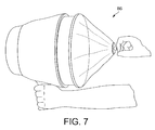
- FIG 7 shows a hand held apparatus 86 for producing a directed flow of air.
- the apparatus is referred to as an "airzooka” and is hand operated by manually pulling a spring loaded diaphragm and then releasing the diaphragm which provides a blast of air. It may be used to direct a blast of air at a targeted one or other of the targets 61A, 61B, 61C.
- an "airzooka" type apparatus may be built into a cannon shaped toy 87.
- the relevant transducer 62A, 62B or 62C When the relevant transducer 62A, 62B or 62C detects the change in barometric pressure, caused by the blast of air, as described with reference to the earlier embodiments, it provides an output signal on the relevant output 83A-83C to the microprocessor 82 which provides an output on the relevant output OPA, OPB or OPC. This causes the relevant actuator 84A, 84B or 84C to release the relevant releasable couplings 64A, 64B, 64C to cause the relevant component of the toy to fall or otherwise move. At the same time, a signal on the output OPD to the sound generator causes the noise to be produced.
- the toy 80 is a pirate ship as shown in Figure 6, the targets are spaced along the side of the pirate ship, and the releasable couplings holding on different parts of the ship, for example a mast and a bow cannon and the stem wheel, then by firing the airzooka at the relevant target, the relevant part of the pirate ship will fall off.
- the sound generator can produce an explosive noise, and if there is provided a light generator, and then a flash of light can be produced.
- toy which include a plurality of spaced transducers which may be selected by movement of air causing a variation of barometric pressure.
Landscapes
- Toys (AREA)
Abstract
A toy comprising a transducer to produce an output signal in response to variations in barometric pressure, a filter to filter said output signal to select a component of the output signal relating to air movement at the transducer and response means to cause said toy to create an effect in response to receipt of the filtered output signal.
Description
- The present invention relates to a toy. By toy we include not only items to be played with by children but also novelty items such as seasonal or gifts of mementos of, for example, a holiday or visit.
- According to one aspect, the present invention comprises a plush toy comprising a transducer to produce an output signal in response to variations in barometric pressure, a filter to filter said output signal to select a component of the output signal relating to air movement at the transducer and response means to cause said toy to create an effect in response to receipt of the filtered output signal.
- As examples, the effect created may be a sound (e.g. a cry or the sound of an explosion), a movement (e.g. of limbs or eyes where the toy is a teddy bear or the like, rotation of a windmill to blow bubbles, apparent breaking up of the toy) or operation of lighting means (e.g. to generate flashes or changes of colour) or other effects.
- According to a further aspect, the present invention comprises a toy comprising a transducer to produce an output signal in response to a person blowing at the transducer, and means to cause said toy to create an effect in response to the filtered output signal.
- According to a further aspect, the present invention comprises a toy comprising a transducer to produce an output signal in response to movement of air caused, for example, by a person blowing at the transducer, and means to cause said toy to create an effect in response to the filtered output signal.
- According to a further aspect, the present invention comprises a toy comprising a transducer to produce an output signal in response to a change of barometric pressure caused, for example, by a person blowing at the transducer, and means to cause said toy to create an effect in response to the filtered output signal.
- According to a further aspect, the present invention comprises a toy comprising a transducer to produce an output signal in response to variations in barometric pressure, means to filter said output signal to select a component of the output signal relating to air movement at the transducer (caused for example by blowing at the toy) and means to cause said toy to create an effect in response to the filtered output signal.
- Thus for example a toy may be provided which creates an effect when a child breathes or blows on it.
- The toy may provide a plush toy such as a teddy bear and the effect created may be a sound effect or a lighting effect or movement of limbs or eyes.
- The toy may alternatively comprise a toy with motor driven parts, the motor driven parts being set in operation by the filtered signal. The motor driven parts may comprise a windmill, or means for producing soap bubbles.
- The toy may comprise a light device, such as a replica candle, and the light may be caused to go out (or come on) by the filtered output signal.
- The toy may comprise a snow globe, that is, a transparent globe with a snow effect within it, and there may be provided a motor means to agitate the snow and the motor means may be controlled by means of the filtered output signal.
- The transducer may comprise a piezo electric device or a microphone such as an electret microphone. The means to filter the output signal may comprise means to remove output signals relating to sound. Thus the filter means may comprise a filter to remove all oscillating signals from the transducer greater than a particular frequency, which may be a very low frequency of up to 10Hz or up to 50Hz whereby the toy will only be operated by small changes in barometric pressure caused by a child blowing on the transducer rather than by background sounds.
- Preferred embodiments to the invention will now be described by way of example only and with reference to the accompanying drawings in which:-
- Figure 1 is a front view of a plush toy in the form of a teddy bear.
- Figure 2 is a front view of a windmill toy,
- Figure 3 is of a snow globe toy,
- Figure 4 is a side view of a toy for producing soap bubbles, and
- Figure 5 is a circuit diagram,
- Figure 6 is a perspective view of a toy which includes a plurality of targets in the form of transducers,
- Figure 7 is an apparatus for providing a directed blast of air, and
- Figure 8 is a circuit diagram for use with the apparatus of Figure 6
- The first embodiment of the invention is shown in Figure 1 which is a front view of a plush toy in the form of a teddy bear. The
teddy bear 10 includes, preferably beneath the plush outer surface in the face region, atransducer 11 in the form of a microphone. The microphone 11 is connected to afirst control circuit 12 which is in turn connected to asecond control circuit 13 which may be for example a sound or light controller. - As will be understood, a child may blow at the teddy bear's face, and the flow of air or change in barometric pressure will be detected by the
microphone 11. The first (trigger)control circuit 12 will cause an output signal to be passed to thesecond control circuit 13 which, if it is a sound controller, will provide a relevant sound. - Thus when the child blows at the teddy bear, the teddy bear may speak or sing or make some other noise.
- If the
sound controller 13 is replaced by, for example, a controller for the lights such as LED's, the teddy bear light up or flash. - If the teddy bear includes motor driven limbs, then the
sound controller 13 may be replaced by a motor controller which causes the limbs to move in response to a child blowing at the teddy bear. - Thus a particularly attractive toy is provided in the form of a teddy bear in which a child may blow a kiss at the teddy bear, the change in barometric pressure being detected by the
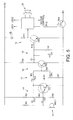
microphone 11 and causing the teddy bear to react by means of sound or light or movement, or a combination. - The electrical circuit for controlling the
teddy bear 10 shown in Figure 1 is illustrated in Figure 5. - The connections between the various components in the circuit will not be described that is clear from the circuit diagram itself.
- The sensing device/
transducer 11 is a low cost electret microphone insert (MIC1). A bias resistor R1 provides the power that is required for this type of two terminal electret microphone. Transistor TR1 and resistors R2, R3 and R4 form afirst stage preamplifier 14 which consists of a single stage preamplifier (common-emitter amp with feedback biasing via R3). An unusual filtering configuration of capacitors C1 and C2 and thefirst stage preamplifier 14 enables this front end to be generally insensitive to and to filter out audio frequencies, but to be sensitive to local changes in barometric pressure or air flow which occurs when a puff or blast of air passes over thetransducer 11. - An output signal from the
preamplifier 14 is fed to asecond gain stage 16 comprising transistor TR2, resistors R5, R6, R7, R8 and variable resistor VR1 via ahigh pass filter 17 formed by C3 and R5. The gain of thesecond stage 16 is preset by means of resistor VR1, which controls the change of barometric pressure (either the value or rate of change), i.e. the level of 'puff', required to trigger. This can be adjusted by quite a large scale. - A DC output signal from the
second stage 16 is passed to adiode pump 18 comprising diode D1, capacitor C4 and bleed resistor R9 which then passes an output signal to an input of a thetrigger stage 19 formed by transistor TR3, resistors R10, R11 and light emitting diode LED1. The LED provides an indicating or flashing light in the bear. - The
trigger stage 19 passes a trigger signal to the input of a controller IC1 (or microcontroller) which in turn operatesloudspeaker 20 and hence outputs sound (and/or lighting effects and/or motor control in the case of a motorised bear). Transistor TR4 forms an electronic switch, so that the sound controller (or microcontroller) can shut down the circuitry and reduce quiescent current to a minimum. - In the circuit of Figure 5 typical values of the components are as follows:-
- TR1
- = MPSA13 (NPN Darlington transistor)
- TR2
- = BC337 (NPN transistor)
- TR3
- = BC548 (NPN transistor)
- D1
- = IN4148 (signal diode)
- IC1
- = W523Axxx (sound controller)
- R1
- = 1kΩ
- R2, R7
- = 22KΩ
- R3, R4, R9
- = 1MΩ
- R5
- = 12KΩ
- R6
- = 47KΩ
- R8, R10
- = 10KΩ
- R11
- = 1KΩ
- R12
- = 2KΩ
- VR1
- = 100KΩ (preset)
- C1, C2, C3
- = 1uF electrolytic
- Corresponding
circuits handle 26 mountingcircuits outer frame 27, awindmill 28, and amotor 25 provided behind thewindmill 27 which can be powered by a battery within thehandle 26. There is provided a transducer in the form of amicrophone 21. The motor may rotate the windmill in response to a child blowing on the transducer. Thecontrol circuits lights 24 which may be in the form of LED's. - A further preferred arrangement of the invention is shown in Figure 3 and comprises a snow globe. This is a conventional globe comprising a hollow generally
transparent globe 30 in which there are provided small particles which give the appearance of the snow. Generally speaking in the base of theglobe 30 there is mounted a model (not shown), for example a model of a building or a forest scene, or something similar. - The
globe 30 is mounted on abase 31 within which is mounted amotor 32 and afan 33. There is provided atransducer 34 comprising a microphone as already described, acircuit 35, and acontroller 36. In use, a child or a person blows on the transducer, and utilising the circuit shown in Figure 5, the motor is energised and rotates the fan which blows the snow like particles upwardly to give the impression of a snowstorm within the globe. - A further preferred embodiment of the invention comprises a toy 40 shown in Figure 4 for producing soap bubbles in response to a child blowing on the transducer, comprising a
handle 46 in which is mounted a battery and the circuit as shown in Figure 5 acircuit 42, and acontroller 43 and theloudspeaker 20 to provide a sound in response to a child blowing on the transducer. The handle mounts aframe 47 on which is mounted amotor 45 with afan 48 attached, and mounted to the front of theframe 47 is afurther frame 49 for mounting soap-engagingportions 50. Atransducer 41 is provided on theframe 47. - In use, therefore, the
frame 49 is inserted into a suitable soap solution and the soap tends to adhere to theportions 50. - Blowing on the
transducer 41 operates the circuit of Figure 5 as already described which operates theelectric motor 45 to rotate thefan 46 and thereby blow soap bubbles off theportions 50. - We have therefore described a circuit which can be used to provide a variety of pleasing effects in different types of toy. It will be noted that surprisingly the
transducer 11 can operate even when buried under plush in a plush toy such as a teddy bear and so has no visible protrusion in that circumstance. The circuit can be made very sensitive so that even very small children can produce enough puff to activate the toy. - It has been found that sufficient change in barometric pressure may be provided when a door to a room is opened which can operate the toy or similar device.
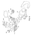
- Referring to Figures 6-8, there is shown in diagrammatic form in Figure 6 a toy which includes a plurality of
targets transducer 11 already described. Thetargets - The toy 60 includes three
component parts component parts 63A-C being connected to the remainder of the toy 60 by means of a respectivereleasable coupling - There may also be provided light means and/or a
sound generator 67. - Within the toy 60 there is provided the
electrical circuit 80 as shown in Figure 8. -
Electrical circuit 80 comprises threecircuits respective transducers circuit 81A-C there may be provided components corresponding topreamplifier 14,high pass filter 17,second gain stage 16, anddiode pump 18. The output of the respective diode pumps 18 are shown at 83A, 83B, 83C. A signal from theseoutputs 83A-C (or an earlier stage) are passed to respective ports IPA, IPB, and IPC of amicroprocessor 82. Themicroprocessor 82 has, for example, four output ports, OPA, OPB, OPC and OPD which are connected respectively to actuators 84A, 84B, 84C, and 84D. Theactuators 84A-C are connected respectively to thereleasable couplings 64A-C (or light unit 66A, 66B, 66C). The actuator OPD is connected to thesound generator 67. - Figure 7 shows a hand held
apparatus 86 for producing a directed flow of air. The apparatus is referred to as an "airzooka" and is hand operated by manually pulling a spring loaded diaphragm and then releasing the diaphragm which provides a blast of air. It may be used to direct a blast of air at a targeted one or other of thetargets - When the
relevant transducer relevant output 83A-83C to themicroprocessor 82 which provides an output on the relevant output OPA, OPB or OPC. This causes therelevant actuator releasable couplings - Thus, for example, if the
toy 80 is a pirate ship as shown in Figure 6, the targets are spaced along the side of the pirate ship, and the releasable couplings holding on different parts of the ship, for example a mast and a bow cannon and the stem wheel, then by firing the airzooka at the relevant target, the relevant part of the pirate ship will fall off. - At the same time the sound generator can produce an explosive noise, and if there is provided a light generator, and then a flash of light can be produced.
- Similar arrangements may be provided with other types of toy which include a plurality of spaced transducers which may be selected by movement of air causing a variation of barometric pressure..
Claims (17)
- A toy comprising a transducer (11,21, 34, 41, 61A, 61B, 61C) to produce an output signal in response to variations in barometric pressure, a filter (17) to filter said output signal to select a component of the output signal relating to air movement at the transducer and response means (13, 20, 25, 24, 33, 48, 50, 63A-C, 64A-C) to cause said toy to create an effect in response to receipt of the filtered output signal.
- A toy as claimed in claim 1 in which the transducer is selected from the group comprising a piezo electric device, a microphone, an electret microphone.
- A toy as claimed in claims 1 or 2 in which the filter comprises a filter to remove output signals relating to sound.
- A toy as claimed in claim 3 in which the filter means comprises a filter to remove all oscillating signals from the transducer greater than a particular frequency.
- A toy as claimed in claim 4 in which the particular frequency is selected from up to 10Hz and up to 50Hz.
- A toy as claimed in any of claims 1 to 5 comprising a plush toy.
- A toy as claimed in claim 6 comprising a teddy bear (10).
- A toy as claimed in claim 6 or 7 in which the plush toy includes limbs, the toy comprising means to move one or more said limbs in response to receipt of the filtered output signal.
- A toy as claimed in any of claims 6 to 8 in which the plush toy includes eyes, the toy comprising means to move one or more said eyes in response to receipt of the filtered output signal
- A toy as claimed in any of claims 6 to 9 in which the plush toy includes sound producing apparatus, the sound producing apparatus being adapted to produce a sound effect in response to receipt of the filtered output signal
- A toy as claimed in any of claims 1 to 5 in which the toy includes at least one motor driven part, the movement of the motor driven part being controlled by receipt of the filtered output signal.
- A toy as claimed in claim 11 in which the motor driven part comprises a windmill.
- A toy as claimed in claim 11 in which the motor driven part comprise means for producing soap bubbles.
- A toy as claimed in claim 12 or 13 further including a light device and including means to vary the light produced by the light device in response to receipt of the filtered output signal.
- A toy as claimed in any of claims 1 to 5 comprising a snow globe, including a motor means to agitate the snow, the motor means being controlled by means of the filtered output signal.
- A toy as claimed in any of claims 1 to 5 in which the transducer is visible and forms a target, and there is also provided a manually operable air flow producing means which may be manually positioned to direct the air flow at the transducer.
- A toy as claimed in claim 16 in which the effect created is one or more of a sound effect or a lighting effect or a movement.
Applications Claiming Priority (1)
| Application Number | Priority Date | Filing Date | Title |
|---|---|---|---|
| GBGB0604624.7A GB0604624D0 (en) | 2006-03-06 | 2006-03-06 | Toy |
Publications (1)
| Publication Number | Publication Date |
|---|---|
| EP1832324A1 true EP1832324A1 (en) | 2007-09-12 |
Family
ID=36241171
Family Applications (1)
| Application Number | Title | Priority Date | Filing Date |
|---|---|---|---|
| EP07103408A Withdrawn EP1832324A1 (en) | 2006-03-06 | 2007-03-02 | Toy |
Country Status (3)
| Country | Link |
|---|---|
| US (1) | US20070207700A1 (en) |
| EP (1) | EP1832324A1 (en) |
| GB (2) | GB0604624D0 (en) |
Cited By (3)
| Publication number | Priority date | Publication date | Assignee | Title |
|---|---|---|---|---|
| US9108115B1 (en) | 2014-08-25 | 2015-08-18 | Silverlit Limited | Toy responsive to blowing or sound |
| EP3000515A1 (en) * | 2014-09-25 | 2016-03-30 | Silverlit Limited | A toy responsive to blowing or sound |
| EP3612285A4 (en) * | 2017-04-21 | 2021-01-20 | Baranoff, Sergei | Self-leveling bubble producing system |
Families Citing this family (7)
| Publication number | Priority date | Publication date | Assignee | Title |
|---|---|---|---|---|
| US7771247B2 (en) | 2005-05-25 | 2010-08-10 | Kessler Brian D | Novelty light-up toy |
| US8496509B2 (en) * | 2009-10-01 | 2013-07-30 | What Kids Want, Inc. | Voice activated bubble blower |
| WO2011082535A1 (en) * | 2010-01-08 | 2011-07-14 | Nokia Corporation | User input |
| US20120282842A1 (en) * | 2011-05-05 | 2012-11-08 | Jakks Pacific, Inc. | Figurine and play set item having an ultraviolet reveal feature |
| USD781961S1 (en) * | 2014-02-27 | 2017-03-21 | Rehco, Llc | Handheld toy device |
| TWI560080B (en) | 2014-05-30 | 2016-12-01 | Ind Tech Res Inst | Electronic device for presenting perceivable content |
| USD885554S1 (en) * | 2018-10-31 | 2020-05-26 | Candyrific, LLC | Novelty fan |
Citations (6)
| Publication number | Priority date | Publication date | Assignee | Title |
|---|---|---|---|---|
| EP0730261A2 (en) * | 1995-03-01 | 1996-09-04 | Seiko Epson Corporation | An interactive speech recognition device |
| US5668780A (en) * | 1992-10-30 | 1997-09-16 | Industrial Technology Research Institute | Baby cry recognizer |
| WO2001043116A1 (en) * | 1999-12-02 | 2001-06-14 | Antakamatics, Inc. | Harmonica having reed vibration conversion capability and associated retrofitting method |
| US20020098879A1 (en) * | 2001-01-19 | 2002-07-25 | Rheey Jin Sung | Intelligent pet robot |
| US20040180603A1 (en) * | 2002-09-11 | 2004-09-16 | Darin Barri | Breath-sensitive toy |
| GB2418728A (en) * | 2004-09-30 | 2006-04-05 | Nicholas Eric Dean Phillips | Motion and Attitude responsive Lighting for a moving object. |
Family Cites Families (4)
| Publication number | Priority date | Publication date | Assignee | Title |
|---|---|---|---|---|
| US6565407B1 (en) * | 2000-02-02 | 2003-05-20 | Mattel, Inc. | Talking doll having head movement responsive to external sound |
| US6669527B2 (en) * | 2001-01-04 | 2003-12-30 | Thinking Technology, Inc. | Doll or toy character adapted to recognize or generate whispers |
| JP3873627B2 (en) * | 2001-01-19 | 2007-01-24 | 株式会社日立製作所 | Radio base station and frequency setting method for radio base station |
| US7191774B2 (en) * | 2003-06-21 | 2007-03-20 | Thorne Robert E | Accurate toy air gun targets |
-
2006
- 2006-03-06 GB GBGB0604624.7A patent/GB0604624D0/en not_active Ceased
-
2007
- 2007-03-01 GB GB0703957A patent/GB2438378A/en not_active Withdrawn
- 2007-03-02 EP EP07103408A patent/EP1832324A1/en not_active Withdrawn
- 2007-03-02 US US11/681,386 patent/US20070207700A1/en not_active Abandoned
Patent Citations (6)
| Publication number | Priority date | Publication date | Assignee | Title |
|---|---|---|---|---|
| US5668780A (en) * | 1992-10-30 | 1997-09-16 | Industrial Technology Research Institute | Baby cry recognizer |
| EP0730261A2 (en) * | 1995-03-01 | 1996-09-04 | Seiko Epson Corporation | An interactive speech recognition device |
| WO2001043116A1 (en) * | 1999-12-02 | 2001-06-14 | Antakamatics, Inc. | Harmonica having reed vibration conversion capability and associated retrofitting method |
| US20020098879A1 (en) * | 2001-01-19 | 2002-07-25 | Rheey Jin Sung | Intelligent pet robot |
| US20040180603A1 (en) * | 2002-09-11 | 2004-09-16 | Darin Barri | Breath-sensitive toy |
| GB2418728A (en) * | 2004-09-30 | 2006-04-05 | Nicholas Eric Dean Phillips | Motion and Attitude responsive Lighting for a moving object. |
Cited By (3)
| Publication number | Priority date | Publication date | Assignee | Title |
|---|---|---|---|---|
| US9108115B1 (en) | 2014-08-25 | 2015-08-18 | Silverlit Limited | Toy responsive to blowing or sound |
| EP3000515A1 (en) * | 2014-09-25 | 2016-03-30 | Silverlit Limited | A toy responsive to blowing or sound |
| EP3612285A4 (en) * | 2017-04-21 | 2021-01-20 | Baranoff, Sergei | Self-leveling bubble producing system |
Also Published As
| Publication number | Publication date |
|---|---|
| GB0703957D0 (en) | 2007-04-11 |
| GB2438378A (en) | 2007-11-28 |
| US20070207700A1 (en) | 2007-09-06 |
| GB0604624D0 (en) | 2006-04-19 |
Similar Documents
| Publication | Publication Date | Title |
|---|---|---|
| EP1832324A1 (en) | Toy | |
| US6491516B1 (en) | Active Hanukkah candelabrum | |
| US10036521B2 (en) | Electrically illuminated flame simulator | |
| US6135604A (en) | Decorative water lamp | |
| EP1434634B1 (en) | Convertible entertainment device | |
| US5847854A (en) | Filtered light signal control suitable for toys | |
| US7398816B2 (en) | Window shade | |
| CN103196094A (en) | Electronic wind-resistant and moisture-proof simulated candle | |
| US6441284B1 (en) | Vertical draft random chiming mechanism | |
| US5266920A (en) | Magnet for use on a refrigerator or the like | |
| US20070190894A1 (en) | Holiday displays having active figurines | |
| US20070207697A1 (en) | Ornamental device with audio player, reciprocating appendage and projection optics | |
| US6623326B2 (en) | Sound-effects generating device with bipolar magnetic switching for activity devices | |
| US6478448B1 (en) | Decorative lighting display system | |
| US10816154B2 (en) | Lighting device | |
| US7025478B1 (en) | Illuminable apparatus | |
| US20230277954A1 (en) | Animated bubble toy customizable and activated by the attachment of an accessory | |
| JP3246720U (en) | Animated bubble toy that can be activated and customized with accessories | |
| US7861664B2 (en) | Toy door knocker, and construction and educational kits including a door knocker | |
| US20050259421A1 (en) | Decorative light switch | |
| JP3128632U (en) | message card | |
| KR200242086Y1 (en) | Recreation Glass | |
| CN215007483U (en) | Voice control type short volume brightening device | |
| RU2685333C1 (en) | Electronic picture | |
| US20230332391A1 (en) | Toilet Light Providing Audible Amusements |
Legal Events
| Date | Code | Title | Description |
|---|---|---|---|
| PUAI | Public reference made under article 153(3) epc to a published international application that has entered the european phase |
Free format text: ORIGINAL CODE: 0009012 |
|
| AK | Designated contracting states |
Kind code of ref document: A1 Designated state(s): AT BE BG CH CY CZ DE DK EE ES FI FR GB GR HU IE IS IT LI LT LU LV MC MT NL PL PT RO SE SI SK TR |
|
| AX | Request for extension of the european patent |
Extension state: AL BA HR MK YU |
|
| AKX | Designation fees paid | ||
| REG | Reference to a national code |
Ref country code: DE Ref legal event code: 8566 |
|
| STAA | Information on the status of an ep patent application or granted ep patent |
Free format text: STATUS: THE APPLICATION IS DEEMED TO BE WITHDRAWN |
|
| 18D | Application deemed to be withdrawn |
Effective date: 20080313 |