EP1808670A2 - Optical determination of the relative positions of objects in space - Google Patents
Optical determination of the relative positions of objects in space Download PDFInfo
- Publication number
- EP1808670A2 EP1808670A2 EP07000302A EP07000302A EP1808670A2 EP 1808670 A2 EP1808670 A2 EP 1808670A2 EP 07000302 A EP07000302 A EP 07000302A EP 07000302 A EP07000302 A EP 07000302A EP 1808670 A2 EP1808670 A2 EP 1808670A2
- Authority
- EP
- European Patent Office
- Prior art keywords
- optical system
- observation
- respect
- mark
- optical
- Prior art date
- Legal status (The legal status is an assumption and is not a legal conclusion. Google has not performed a legal analysis and makes no representation as to the accuracy of the status listed.)
- Withdrawn
Links
Images

Classifications
-
- G—PHYSICS
- G01—MEASURING; TESTING
- G01B—MEASURING LENGTH, THICKNESS OR SIMILAR LINEAR DIMENSIONS; MEASURING ANGLES; MEASURING AREAS; MEASURING IRREGULARITIES OF SURFACES OR CONTOURS
- G01B11/00—Measuring arrangements characterised by the use of optical techniques
- G01B11/002—Measuring arrangements characterised by the use of optical techniques for measuring two or more coordinates
-
- G—PHYSICS
- G01—MEASURING; TESTING
- G01B—MEASURING LENGTH, THICKNESS OR SIMILAR LINEAR DIMENSIONS; MEASURING ANGLES; MEASURING AREAS; MEASURING IRREGULARITIES OF SURFACES OR CONTOURS
- G01B11/00—Measuring arrangements characterised by the use of optical techniques
- G01B11/26—Measuring arrangements characterised by the use of optical techniques for measuring angles or tapers; for testing the alignment of axes
- G01B11/275—Measuring arrangements characterised by the use of optical techniques for measuring angles or tapers; for testing the alignment of axes for testing wheel alignment
- G01B11/2755—Measuring arrangements characterised by the use of optical techniques for measuring angles or tapers; for testing the alignment of axes for testing wheel alignment using photoelectric detection means
-
- G—PHYSICS
- G01—MEASURING; TESTING
- G01B—MEASURING LENGTH, THICKNESS OR SIMILAR LINEAR DIMENSIONS; MEASURING ANGLES; MEASURING AREAS; MEASURING IRREGULARITIES OF SURFACES OR CONTOURS
- G01B2210/00—Aspects not specifically covered by any group under G01B, e.g. of wheel alignment, caliper-like sensors
- G01B2210/10—Wheel alignment
- G01B2210/12—Method or fixture for calibrating the wheel aligner
-
- G—PHYSICS
- G01—MEASURING; TESTING
- G01B—MEASURING LENGTH, THICKNESS OR SIMILAR LINEAR DIMENSIONS; MEASURING ANGLES; MEASURING AREAS; MEASURING IRREGULARITIES OF SURFACES OR CONTOURS
- G01B2210/00—Aspects not specifically covered by any group under G01B, e.g. of wheel alignment, caliper-like sensors
- G01B2210/10—Wheel alignment
- G01B2210/14—One or more cameras or other optical devices capable of acquiring a two-dimensional image
- G01B2210/143—One or more cameras on each side of a vehicle in the main embodiment
-
- G—PHYSICS
- G01—MEASURING; TESTING
- G01B—MEASURING LENGTH, THICKNESS OR SIMILAR LINEAR DIMENSIONS; MEASURING ANGLES; MEASURING AREAS; MEASURING IRREGULARITIES OF SURFACES OR CONTOURS
- G01B2210/00—Aspects not specifically covered by any group under G01B, e.g. of wheel alignment, caliper-like sensors
- G01B2210/10—Wheel alignment
- G01B2210/30—Reference markings, reflector, scale or other passive device
- G01B2210/303—Reference markings, reflector, scale or other passive device fixed to the ground or to the measuring station
Definitions
- the present invention relates to an optical installation for determining the relative positions of at least two objects in space, of the type comprising at least two optical systems each associated with an observation frame, the optical systems being each adapted for the determination of the position of an object in space with respect to its observation mark, from an image of the object picked up by said optical system.
- It also relates to a method for determining the relative positions of at least two objects in space, of the type using at least two optical systems each associated with an observation frame, the optical systems being each adapted for determination. the position of an object in space with respect to its observation mark, from an image of the object picked up by said optical system.
- the optical systems are formed by independent cameras, or a single camera associated with sets of lenses defining distinct optical paths for the same incident beam.
- the optical systems allow the simultaneous observation of the wheels of the vehicle, and from the images thereof, to determine their relative positions.
- the devices described in these documents provide for rigid mechanical structures on which the optical systems are immobilized.
- the purpose of the invention is to propose an optical installation and method for determining the relative positions, in space, of at least two objects, in particular vehicle wheels, the installation having a small footprint, an implementation easy, and reduced sensitivity to the rigorous conditions encountered in a garage.
- the subject of the invention is an optical installation for determining the relative positions of at least two objects in space, of the aforementioned type, characterized in that the optical systems are movable relative to one another, an optical system constituting a reference optical system comprises a set of reference points of known geometrical configuration, the set of reference points being immobilized in a known position with respect to the observation frame of the optical system reference, and visible from the or each other optical system in the absence of objects, in that the or each other optical system comprises means for analyzing an image of all the reference points and means of positioning of the set of reference points relative to its observation mark, and in that it comprises means for deducing the position of the observation mark from the each other optical system with respect to the observation mark of the reference optical system, from the position of the set of reference points with respect to each observation mark, and from the known position of the set of points reference relative to the reference frame of the reference optical system.
- the invention also relates to an installation comprising four optical systems intended to be arranged substantially at the vertices of a quadrilateral for the determination of the relative positions of four objects in space, the objects being disposed within the defined area.
- the quadrilateral characterized in that it comprises two optical installations as defined above, the set of reference points of a first reference optical system being visible from the second optical reference system in the absence of Objects, in that the second reference optical system comprises means for analyzing an image of all the reference points of the first reference optical system and means for positioning all the reference points relative to each other.
- each optical system comprises means for deducing the position of the observation mark of the second op system reference signal with respect to the observation frame of the first reference optical system, from the position of the set of reference points of the first reference optical system with respect to the observation frame of the second reference optical system, and the known position of the set of reference points of the first reference optical system with respect to the observation frame of the first reference optical system, and in that it comprises means for deducing the relative positions of the reference marks from the reference optical system. observation of each optical system.
- the invention further relates to an optical method for determining the relative positions of at least two objects in space, of the aforementioned type, characterized in that the optical systems are movable relative to each other, in that an optical system constituting a reference optical system of a set of reference points of known geometric configuration is provided, the set of reference points being immobilized in a known position with respect to the observation frame of the system optical reference, and visible from the or each other optical system in the absence of objects, in that the or each other optical system analyzes an image of all reference points and determines the positioning of all points reference relative to its observation mark, and in that one deduces the position of the observation mark of the or each other optical system with respect to the obs marker. ervation of the reference optical system, from the position of the set of reference points with respect to each observation frame, and the known position of the set of reference points with respect to the observation frame of the optical reference system.
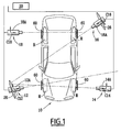
- FIG. 1 The installation shown in FIG. 1 is intended to determine, optically, the relative positions of the four wheels R of a motor vehicle designated by reference numeral 10.
- the installation comprises four optical systems 12, 14, 16, 18 each associated with a wheel R of the vehicle. They each include a CCD video camera rated 12A, 14A, 16A, 18A. These four cameras are connected to a central information processing unit 20 formed for example by a computer adapted to process the images received.
- the optical systems 12, 14, 16, 18 are movable relative to one another around the vehicle 10.
- the optical systems are arranged motionless at the four corners of a quadrilateral, in particular a surrounding rectangle. the vehicle.
- the optical system 12 is shown in perspective in FIGS. 2A and 2B.
- the video camera 12A is supported by a tripod 24 adapted to be placed on the ground.
- the camera 12A is secured to a target 26 defining a visible mark (O, xyz) noted A12, and visible in Figure 2A.
- the target 26 is immobilized by mechanical means relative to the structure of the camera and in particular with respect to its observation mark (O ', x'y'z') denoted C12.
- the observation mark C12 is linked to the image acquisition member 28 of the camera 12A and in particular to its CCD sensor.
- the optical system 12 constitutes a reference optical system.
- the optical system 16, disposed in the corner opposite to the vehicle in the configuration of Figure 1 also constitutes a reference optical system and has a structure identical to that of the optical system 12.
- optical systems 14 and 18 are devoid of target and include a single video camera 14A, 18A carried by a support tripod.
- the optical systems 14 and 18 are of the same structure as the optical systems 12 and 16.
- the four optical systems are optical reference systems, which allows redundant measurements and therefore a greater reliability of the result of these measurements.
- the target 26 is formed, for example, by a disc of center O at the periphery of which twelve coplanar points 26A are distributed.
- the target 26 has a thirteenth point 26B disposed in front of the main plane of the disk having the twelve points 26A.
- This point angularly particularizes the disk 26 and makes it possible to define two orthogonal axes, Ox and Oy in the plane of the target.
- the axis Oy advantageously passes to the right of point 26B.
- the target 26 has a principal axis of symmetry defined by the twelve coplanar points regularly distributed at the periphery of the disk.
- the main axis of symmetry forms an axis Oz perpendicular to the axes Ox, Oy.
- the axes Ox, Oy, Oz and the point O define the visible mark A12.
- the target 26 constitutes a set of reference points of known geometric configuration defining the visible mark A12. It is immobilized in a determinable position relative to the C12 observation mark of the camera.
- the observation mark C12 has the center of the camera CCD 12A as the center of the center, denoted by O '.
- the observation marker is defined by a trihedron (O'x ', O'y', O'z '), where O'z' is the optical axis of the camera, O'x 'is an axis parallel to Horizontal pixel lines of the CCD sensor and O'y 'is an axis parallel to the vertical columns of pixels of the CCD sensor.
- the geometrical configuration of all the reference points of the target 26 is stored in the information processing unit 20.
- the information processing unit 20 comprises means for implementing algorithms for determining the position of an object in space.
- it is adapted to determine the position of an object carrying a set of reference points arranged in a known geometric configuration, this configuration being previously stored in the unit 20. This position is determined from the image of this object taken by a camera connected to the information processing unit. The position of the object in space is calculated with respect to the observation frame C12 of the camera.
- the implemented algorithm is of any suitable type and for example of the type described in the application WO 94/05969 .
- each camera determines its intrinsic characteristics (observation mark, focal length, pixel size or pixels, radial distortion, tangential distortion) and its extrinsic characteristics (rotation and translation matrices which , applied to the observed object, form an image strictly identical to the image observed by the camera free of its distortions).
- the corrections to be made to the images produced are thus determined by known methods to determine a correct position of an object in space.
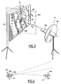
- FIG. 3 illustrates the method implemented to determine the relative position of the two marks C12 and A12 specific to the optical system 12. The method used for the optical system 16 is similar.
- the optical system 12 is arranged facing the reflecting face of a plane mirror 50.
- This mirror is suspended from a bracket 52.
- the suspension means are adapted for a free rotation of the mirror around a mirror. vertical axis ⁇ .
- the mirror 50 has on its reflecting face a set of reference marks 54A constituted by black disks distributed, in a known geometric figure such as a square, at the periphery of the mirror.
- An additional reference mark 54B is disposed in front of the reflecting face of the mirror 50.
- the geometric configuration of the marks of reference 54A and 54B is known and stored in the information processing unit 20.
- the normal to the mirror 50 is denoted n.
- This normal is perpendicular to the mirror and passes through the center of the figure delimited by the set of marks 54A and 54B.
- the mirror has a proper mark (O m , x m y m z m ) whose center O m is the center of the figure delimited by the marks 54A.
- the axis O m z m extends according to the normal n.
- the axes O m x m , and O m y m extend perpendicularly to one another in the plane of the mirror 50.
- the axis O m y m extends parallel to the axis ⁇ .
- the target 26, carrying all the reference points 26A and 26B, is reflected on the reflecting surface of the mirror 50 and forms on the mirror an image of the target denoted 56.
- the camera 12A collects, in the observation frame C12, an image of the reflecting face of the mirror 50 comprising on the one hand all the reference marks 54A and 54B, and on the other hand the reflected image 56 of the target carried by the optical system.
- the camera 12A being connected to the information processing unit 20, the latter determines, from the stored algorithm, the position of the mirror 50 with respect to the observation frame C12 from the image taken from the set of reference marks 54A and 54B carried by the mirror.
- the information processing unit 20 determines, by implementing the stored algorithm, the position of the virtual image of the target 26 relative to the observation frame C12 of the camera. More particularly, the information processing unit 20 determines the position of a virtual visible mark (O ", x" y "z") associated with the virtual image of the target 26 with respect to the observation mark ( O ', x'y'z') of the camera.
- a virtual visible mark O ", x" y "z"
- the virtual visible mark (O ", x" y “z”) is the virtual image of the visible mark (O, xyz) obtained by reflection in the mirror 50.
- the central information processing unit 20 determines the position of the mark observation (O ', x'y'z') of the camera, with respect to the visible mark (O, xyz) defined by the target 26.
- the information processing unit 20 proceeds as follows.
- the position of the virtual image, corresponding to the image 56 of the target and obtained by reflection in the mirror 50, is determined by analysis of the image collected by the 12A camera.
- the information processing unit 20 determines the position of the mirror 50, and in particular of its associated coordinate system (O m , x m y m z m ) in the observation frame (O ', x'y'z ') linked to the camera. For this purpose, the information processing unit 20 analyzes the image of the mirror 50 collected by the camera and determines the position of the mirror 50 from the analysis of the position of the reference marks 54A and 54B appearing on the camera. 'picture.
- the coordinates (x ", y", z ") of the virtual image in the virtual visible coordinate system of the coordinate point M (x, y, z) in the visible coordinate system are obtained by applying the diagonal matrix Next z : 1 0 0 0 0 1 0 0 0 0 - 1 0 0 0 0 1
- M o ' M ov ' * S z
- M o ' is thus the matrix of passage of the reference of the mirror (O m , x m y m z m ) to the visible mark (O, xyz).
- the central information processing unit 20 can, by implementing the calculation described above, determine the position of the observation frame C12 associated with the camera with respect to the visible mark A12 associated with the target 26 attached to this camera.
- an image of mirror 50 is determined in a first position thereof, shown in bold lines in FIG. 3.
- the mirror is then moved to a second position shown in phantom in FIG. displacement is performed around the axis ⁇ suspension of the mirror.
- This axis ⁇ corresponds to the vertical of the site of operation of the installation.
- the central information processing unit 20 determines, for the two positions of the mirror, the coordinates of the planes in which the mirror extends.
- the line ⁇ corresponds to the intersection of the two planes thus determined.
- the central information processing unit 20 thus determines the relative position of the reference optical system with respect to a family of horizontal planes which are of capital importance for the particular case of vehicle geometry.
- FIG. 4 diagrammatically shows the optical systems 12 and 14 facing each other, in the absence of the motor vehicle 10.
- the optical systems 12 and 14 are arranged, as in FIG. 1, facing each other with sufficient space to allow passage of the vehicle 10.
- the matrix of passage between the C12 observation mark and the visible mark A12 is known, since determined according to the method described above.
- the optical system 14 In order to determine the relative positions of the observation marks C12 and C14, the optical system 14 produces, under the control of the information processing unit 20, an image of the target 26. This image is processed by the unit information processing 20.
- the latter knowing the geometrical configuration of all the reference points of the target 26, determines, by implementing the stored algorithm, the relative position of the target 26 with respect to the observation frame C14 of the system observing optical. It thus deduces the position of the visible mark A12 defined by the target 26 relative to the observation mark C14.
- the central information processing unit 20 determines the relative positions of the observation marks C12 and C14.
- the central information processing unit 20 determines the relative position between the observation marks associated with the two opposite optical systems 12 and 14.
- the optical system 16 disposed on the opposite side of the optical system 12 relative to the location of the vehicle 10 observes the target 26 carried by the optical system 12 in the absence of a vehicle.
- the information processing unit 20 determines the position of the observation mark, denoted C16, associated with the optical system 16 with respect to the observation mark C12 of the reference optical system.
- the optical system 16 is also provided with a target immobilized with respect to the camera incorporated in this optical system, the observation thereof from the optical system 18 enables the central information processing unit 20, to determine the position of the observed observation mark C18 associated with the optical system 18 with respect to the observation frame C16 of the reference optical system 16.
- observation marks C16 and C18 are derived from the relative positions of the visible mark of the target carried by the optical system 16 and of the observation mark associated with the optical system 16.
- the four optical systems can no longer observe each other. However, each of them is likely to take an image of a wheel R of the vehicle.
- each wheel is provided with a target or applies 60 connected rigidly and in a known manner to the wheel.
- Each applique comprises a set of marks distributed in a known geometric configuration and stored in the information processing unit 20.
- the central information processing unit 20 Before determining the relative positions of the sconces and therefore those of the wheels, it is necessary to take into account the fog of each sconce and its offset so that the central information processing unit 20 takes it into account in subsequent calculations. .
- the unit 20 analyzes several images of each wheel taken in specific positions determined.
- the central information processing unit 20 determines the relative position of each wheel relative to the observation frame of the associated camera as known per se. Indeed, the center of the wheels being known, the horizontal planes being known, their section with the plane of the wheels being known, the vertical of the place being known, it is easy to find the angles and the characteristic distances of the geometry of the vehicle.
- the central information processing unit 20 deduces the relative positions of the four wheels of the vehicle. It is thus possible to determine the geometry of the vehicle and to perform any adjustment operation necessary for the satisfactory operation of the vehicle.
- the position of the four optical systems can be modified for each vehicle.
- the unit 20 again determines the relative positions of the observation marks associated with the different optical systems, according to the method explained above.
- the installation is of a small footprint and can be stored easily outside the phases of use.
- the installation and the method described here are generalizable to any number of cameras referenced to each other. Thus, it is possible to measure the vehicle in different attitudes and at different heights.
Abstract
Description
La présente invention concerne une installation optique de détermination des positions relatives d'au moins deux objets dans l'espace, du type comportant au moins deux systèmes optiques chacun associé à un repère d'observation, les systèmes optiques étant adaptés chacun pour la détermination de la position d'un objet dans l'espace par rapport à son repère d'observation, à partir d'une image de l'objet relevée par ledit système optique.The present invention relates to an optical installation for determining the relative positions of at least two objects in space, of the type comprising at least two optical systems each associated with an observation frame, the optical systems being each adapted for the determination of the position of an object in space with respect to its observation mark, from an image of the object picked up by said optical system.
Elle concerne en outre un procédé de détermination des positions relatives d'au moins deux objets dans l'espace, du type mettant en oeuvre au moins deux systèmes optiques chacun associé à un repère d'observation, les systèmes optiques étant adaptés chacun pour la détermination de la position d'un objet dans l'espace par rapport à son repère d'observation, à partir d'une image de l'objet relevée par ledit système optique.It also relates to a method for determining the relative positions of at least two objects in space, of the type using at least two optical systems each associated with an observation frame, the optical systems being each adapted for determination. the position of an object in space with respect to its observation mark, from an image of the object picked up by said optical system.
Pour le contrôle de la géométrie d'un véhicule automobile, il est nécessaire de connaître les positions relatives des roues du véhicule. Ces informations permettent de contrôler et d'éventuellement corriger le parallélisme des roues et en particulier la géométrie du véhicule.For the control of the geometry of a motor vehicle, it is necessary to know the relative positions of the wheels of the vehicle. This information makes it possible to check and possibly correct the parallelism of the wheels and in particular the geometry of the vehicle.
A cet effet, on connaît différentes installations et procédés permettant, à l'aide de plusieurs systèmes optiques observant chacun une roue du véhicule, de déterminer les positions relatives de ces roues. De tels dispositifs et procédés sont décrits par exemple dans les documents
Dans ces installations, les systèmes optiques sont formés par des caméras indépendantes, ou une caméra unique associée à des ensembles de lentilles définissant des chemins optiques distincts pour un même faisceau incident. Les systèmes optiques permettent l'observation simultanée des roues du véhicule, et, à partir des images de celles-ci, de déterminer leurs positions relatives.In these installations, the optical systems are formed by independent cameras, or a single camera associated with sets of lenses defining distinct optical paths for the same incident beam. The optical systems allow the simultaneous observation of the wheels of the vehicle, and from the images thereof, to determine their relative positions.
A cet effet, il est nécessaire que les différents systèmes optiques soient dans des positions relatives connues, sans quoi il est impossible de corréler les informations obtenues à partir des images de chaque roue. Pour garantir des positions relatives fixes des systèmes optiques les uns par rapport aux autres, les dispositifs décrits dans ces documents prévoient des structures mécaniques rigides sur lesquelles sont immobilisés les systèmes optiques.For this purpose, it is necessary that the different optical systems are in known relative positions, otherwise it is impossible to correlate the information obtained from the images of each wheel. In order to guarantee relative fixed positions of the optical systems with respect to each other, the devices described in these documents provide for rigid mechanical structures on which the optical systems are immobilized.
La présence de telles structures mécaniques rigides rend l'installation encombrante. De plus, celle-ci est fragile puisque la déformation, par exemple suite à un choc involontaire, des structures mécaniques rigides conduit à des erreurs de mesure des positions relatives des roues du véhicule.The presence of such rigid mechanical structures makes the installation cumbersome. In addition, it is fragile since the deformation, for example following an unintentional shock, rigid mechanical structures leads to errors in measuring the relative positions of the vehicle wheels.
L'invention a pour but de proposer une installation et un procédé optiques de détermination des positions relatives, dans l'espace, d'au moins deux objets, notamment des roues de véhicules, l'installation ayant un encombrement réduit, une mise en oeuvre aisée, et une sensibilité réduite aux conditions rigoureuses rencontrées dans un garage.The purpose of the invention is to propose an optical installation and method for determining the relative positions, in space, of at least two objects, in particular vehicle wheels, the installation having a small footprint, an implementation easy, and reduced sensitivity to the rigorous conditions encountered in a garage.
A cet effet, l'invention a pour objet une installation optique de détermination des positions relatives d'au moins deux objets dans l'espace, du type précité, caractérisée en ce que les systèmes optiques sont déplaçables les uns par rapport aux autres, en ce qu'un système optique, constituant un système optique de référence, comporte un ensemble de points de référence, de configuration géométrique connue, l'ensemble des points de référence étant immobilisé dans une position connue par rapport au repère d'observation du système optique de référence, et visible depuis le ou chaque autre système optique en l'absence des objets, en ce que le ou chaque autre système optique comporte des moyens d'analyse d'une image de l'ensemble des points de référence et des moyens de positionnement de l'ensemble des points de référence par rapport à son repère d'observation, et en ce qu'elle comporte des moyens de déduction de la position du repère d'observation du ou de chaque autre système optique par rapport au repère d'observation du système optique de référence, à partir de la position de l'ensemble des points de référence par rapport à chaque repère d'observation, et de la position connue de l'ensemble des points de référence par rapport au repère d'observation du système optique de référence.For this purpose, the subject of the invention is an optical installation for determining the relative positions of at least two objects in space, of the aforementioned type, characterized in that the optical systems are movable relative to one another, an optical system constituting a reference optical system comprises a set of reference points of known geometrical configuration, the set of reference points being immobilized in a known position with respect to the observation frame of the optical system reference, and visible from the or each other optical system in the absence of objects, in that the or each other optical system comprises means for analyzing an image of all the reference points and means of positioning of the set of reference points relative to its observation mark, and in that it comprises means for deducing the position of the observation mark from the each other optical system with respect to the observation mark of the reference optical system, from the position of the set of reference points with respect to each observation mark, and from the known position of the set of points reference relative to the reference frame of the reference optical system.
Suivant des modes particuliers de réalisation, l'installation optique comporte l'une ou plusieurs des caractéristiques suivantes :
- chaque système optique comporte une caméra vidéo supportée par un pied et reliée à une même unité centrale de traitement d'informations ;
- ledit ensemble de points de référence comporte un groupe de marques visibles discrètes coplanaires ainsi qu'au moins une marque visible non coplanaire ; et
- elle comporte des appliques adaptées pour être solidarisées chacune à un objet dans une position connue, et chaque système optique comporte des moyens de détermination de la position d'une applique dans l'espace par rapport à son repère d'observation et des moyens de déduction de la position de l'objet par rapport à son repère d'observation à partir de la position déterminée de l'applique par rapport à son repère d'observation et de la position connue de l'applique par rapport à l'objet.
- each optical system comprises a video camera supported by a foot and connected to the same central information processing unit;
- said set of reference points comprises a group of coplanar discrete visible marks as well as at least one non-coplanar visible mark; and
- it comprises appliques adapted to be each secured to an object in a known position, and each optical system comprises means for determining the position of an applique in space with respect to its observation frame and means of deduction the position of the object relative to its observation mark from the determined position of the applique relative to its observation mark and the known position of the applique relative to the object.
L'invention a également pour objet une installation comportant quatre systèmes optiques destinés à être disposés sensiblement aux sommets d'un quadrilatère pour la détermination des positions relatives de quatre objets dans l'espace, les objets étant disposés à l'intérieur de la zone délimitée par le quadrilatère, caractérisée en ce qu'elle comporte deux installations optiques telles que définies ci-dessus, l'ensemble des points de référence d'un premier système optique de référence étant visible depuis le second système optique de référence en l'absence des objets, en ce que le second système optique de référence comporte des moyens d'analyse d'une image de l'ensemble des points de référence du premier système optique de référence et des moyens de positionnement de l'ensemble des points de référence par rapport à son repère d'observation, en ce qu'elle comporte des moyens de déduction de la position du repère d'observation du second système optique de référence par rapport au repère d'observation du premier système optique de référence, à partir de la position de l'ensemble des points de référence du premier système optique de référence par rapport au repère d'observation du second système optique de référence, et de la position connue de l'ensemble des points de référence du premier système optique de référence par rapport au repère d'observation du premier système optique de référence, et en ce qu'elle comporte des moyens de déduction des positions relatives des repères d'observation de chaque système optique.The invention also relates to an installation comprising four optical systems intended to be arranged substantially at the vertices of a quadrilateral for the determination of the relative positions of four objects in space, the objects being disposed within the defined area. by the quadrilateral, characterized in that it comprises two optical installations as defined above, the set of reference points of a first reference optical system being visible from the second optical reference system in the absence of Objects, in that the second reference optical system comprises means for analyzing an image of all the reference points of the first reference optical system and means for positioning all the reference points relative to each other. at its observation mark, in that it comprises means for deducing the position of the observation mark of the second op system reference signal with respect to the observation frame of the first reference optical system, from the position of the set of reference points of the first reference optical system with respect to the observation frame of the second reference optical system, and the known position of the set of reference points of the first reference optical system with respect to the observation frame of the first reference optical system, and in that it comprises means for deducing the relative positions of the reference marks from the reference optical system. observation of each optical system.
L'invention a en outre pour objet un procédé optique de détermination des positions relatives d'au moins deux objets dans l'espace, du type précité, caractérisé en ce que les systèmes optiques sont déplaçables les uns par rapport aux autres, en ce que l'on munit un système optique, constituant un système optique de référence d'un ensemble de points de référence, de configuration géométrique connue, l'ensemble de points de référence étant immobilisé dans une position connue par rapport au repère d'observation du système optique de référence, et visible depuis le ou chaque autre système optique en l'absence des objets, en ce que le ou chaque autre système optique analyse une image de l'ensemble des points de référence et détermine le positionnement de l'ensemble des points de référence par rapport à son repère d'observation, et en ce que l'on déduit la position du repère d'observation du ou de chaque autre système optique par rapport au repère d'observation du système optique de référence, à partir de la position de l'ensemble des points de référence par rapport à chaque repère d'observation, et de la position connue de l'ensemble des points de référence par rapport au repère d'observation du système optique de référence.The invention further relates to an optical method for determining the relative positions of at least two objects in space, of the aforementioned type, characterized in that the optical systems are movable relative to each other, in that an optical system constituting a reference optical system of a set of reference points of known geometric configuration is provided, the set of reference points being immobilized in a known position with respect to the observation frame of the system optical reference, and visible from the or each other optical system in the absence of objects, in that the or each other optical system analyzes an image of all reference points and determines the positioning of all points reference relative to its observation mark, and in that one deduces the position of the observation mark of the or each other optical system with respect to the obs marker. ervation of the reference optical system, from the position of the set of reference points with respect to each observation frame, and the known position of the set of reference points with respect to the observation frame of the optical reference system.
L'invention sera mieux comprise à la lecture de la description qui va suivre, donnée uniquement à titre d'exemple et faite en se référant aux dessins, sur lesquels :
- la figure 1 est une vue de dessus d'une installation optique selon l'invention adaptée pour déterminer les positions relatives des quatre roues d'un véhicule automobile ;
- les figures 2A et 2B sont des vues en perspective d'un même système optique de référence du dispositif de la figure 1 sur lesquelles sont représentés respectivement un repère d'observation propre à l'organe de recueil d'image et un repère visible défini par un ensemble de points de référence;
- la figure 3 est une vue en perspective d'un système optique de référence disposé face à un miroir qui est déplaçable entre deux positions, afin de déterminer la position du repère d'observation du système optique par rapport à son repère visible ; et
- la figure 4 est une vue schématique illustrant la détermination selon l'invention des positions relatives des repères d'observation de deux systèmes optiques en regard.
- Figure 1 is a top view of an optical installation according to the invention adapted to determine the relative positions of the four wheels of a motor vehicle;
- FIGS. 2A and 2B are perspective views of the same reference optical system of the device of FIG. 1, on which are respectively represented an observation frame specific to the image collection member and a visible reference mark defined by FIG. a set of reference points;
- FIG. 3 is a perspective view of a reference optical system arranged facing a mirror that is movable between two positions, in order to determine the position of the observation mark of the optical system with respect to its visible mark; and
- FIG. 4 is a schematic view illustrating the determination according to the invention of the relative positions of the observation marks of two opposite optical systems.
L'installation représentée sur la figure 1 est destinée à déterminer, de manière optique, les positions relatives des quatre roues R d'un véhicule automobile désigné par la référence 10.The installation shown in FIG. 1 is intended to determine, optically, the relative positions of the four wheels R of a motor vehicle designated by
L'installation comporte quatre systèmes optiques 12, 14, 16, 18 associés chacun à une roue R du véhicule. Ils comportent chacun une caméra vidéo CCD notée 12A, 14A, 16A, 18A. Ces quatre caméras sont reliées à une unité centrale de traitement d'informations 20 formée par exemple par un ordinateur adapté pour traiter les images reçues.The installation comprises four
Les systèmes optiques 12, 14, 16, 18 sont déplaçables les uns par rapport aux autres autour du véhicule 10. Pour un fonctionnement correct de l'installation, les systèmes optiques sont disposés immobiles aux quatre sommets d'un quadrilatère, notamment un rectangle entourant le véhicule.The
Le système optique 12 est représenté en perspective sur les figures 2A et 2B. La caméra vidéo 12A est supportée par un trépied 24 adapté pour être posé sur le sol. En outre, la caméra 12A est solidaire d'une cible 26 définissant un repère visible (O,xyz) noté A12, et visible sur la figure 2A. La cible 26 est immobilisée par des moyens mécaniques par rapport à la structure de la caméra et notamment par rapport à son repère d'observation (O',x'y'z') noté C12. Le repère d'observation C12 est lié à l'organe 28 de recueil d'image de la caméra 12A et notamment à son capteur CCD.The
Le système optique 12 constitue un système optique de référence. De même, le système optique 16, disposé dans le coin opposé par rapport au véhicule dans la configuration de la figure 1, constitue également un système optique de référence et a une structure identique à celle du système optique 12.The
Au contraire, les systèmes optiques 14 et 18 sont dépourvus de cible et comportent une simple caméra vidéo 14A, 18A portée par un trépied de support.In contrast, the
En variante, les systèmes optiques 14 et 18 sont de même structure que les systèmes optiques 12 et 16. Dans ce cas, les quatre systèmes optiques sont des systèmes optiques de référence, ce qui permet des mesures redondantes et donc une plus grande fiabilité du résultat de ces mesures.As a variant, the
Comme représenté sur la figure 2A, la cible 26 est formée, par exemple, par un disque de centre O à la périphérie duquel sont répartis douze points coplanaires 26A. En outre, la cible 26 comporte un treizième point 26B disposé en avant du plan principal du disque comportant les douze points 26A.As shown in FIG. 2A, the
Ce point particularise angulairement le disque 26 et permet de définir deux axes orthogonaux, Ox et Oy dans le plan de la cible. L'axe Oy passe avantageusement au droit du point 26B.This point angularly particularizes the
La cible 26 présente un axe principal de symétrie défini par les douze points coplanaires répartis régulièrement à la périphérie du disque. L'axe principal de symétrie forme un axe Oz perpendiculaire aux axes Ox, Oy.The
Les axes Ox, Oy, Oz et le point O définissent le repère visible A12.The axes Ox, Oy, Oz and the point O define the visible mark A12.
Ainsi, la cible 26 constitue un ensemble de points de référence, de configuration géométrique connue définissant le repère visible A12. Celui-ci est immobilisé dans une position déterminable par rapport au repère d'observation C12 de la caméra.Thus, the
Comme représenté sur la figure 2B, le repère d'observation C12 a pour centre, noté O', le centre du capteur CCD de la caméra 12A. Le repère d'observation est défini par un trièdre (O'x', O'y', O'z'), où O'z' est l'axe optique de la caméra, O'x' est un axe parallèle aux lignes horizontales de pixels du capteur CCD et O'y' est un axe parallèle aux colonnes verticales de pixels du capteur CCD.As shown in FIG. 2B, the observation mark C12 has the center of the
La configuration géométrique de l'ensemble des points de référence de la cible 26 est mémorisée dans l'unité de traitement d'informations 20.The geometrical configuration of all the reference points of the
L'unité de traitement d'informations 20 comporte des moyens de mise en oeuvre d'algorithmes de détermination de la position d'un objet dans l'espace. En particulier, elle est adaptée pour déterminer la position d'un objet portant un ensemble de points de référence disposés suivant une configuration géométrique connue, cette configuration étant préalablement mémorisée dans l'unité 20. Cette position est déterminée à partir de l'image de cet objet prise par une caméra reliée à l'unité de traitement d'informations. La position de l'objet dans l'espace est calculée par rapport au repère d'observation C12 de la caméra. L'algorithme mis en oeuvre est de tout type adapté et par exemple du type de celui décrit dans la demande
En vue de la mise en oeuvre de tels algorithmes, il convient d'utiliser des caméras préalablement étalonnées pour compenser les erreurs résultant des imperfections de la caméra et du capteur qu'elle comporte.In order to implement such algorithms, it is necessary to use previously calibrated cameras to compensate for errors resulting from camera and sensor imperfections.
A cet effet, on détermine, pour chaque caméra, ses caractéristiques intrinsèques (repère d'observation, distance focale, taille des éléments d'image ou pixels, distorsion radiale, distorsion tangentielle) et ses caractéristiques extrinsèques (matrices de rotation et de translation qui, appliquées à l'objet observé, forment une image strictement identique à l'image observée par la caméra débarrassée de ses distorsions). On détermine ainsi par des méthodes connues les corrections devant être apportées aux images produites afin de déterminer une position correcte d'un objet dans l'espace.For this purpose, for each camera, it determines its intrinsic characteristics (observation mark, focal length, pixel size or pixels, radial distortion, tangential distortion) and its extrinsic characteristics (rotation and translation matrices which , applied to the observed object, form an image strictly identical to the image observed by the camera free of its distortions). The corrections to be made to the images produced are thus determined by known methods to determine a correct position of an object in space.
Pour la mise en oeuvre du procédé selon l'invention, il est nécessaire de connaître, pour chaque système optique de référence 12, 16, les positions relatives du repère d'observation de la caméra, et du repère visible défini par la cible. En effet, il est extrêmement délicat, voire impossible, lors de l'immobilisation de la cible sur la caméra, de fixer celle-ci de sorte que les deux repères C12 et A12 soient exactement confondus.For the implementation of the method according to the invention, it is necessary to know, for each
Sur la figure 3 est illustré le procédé mis en oeuvre pour déterminer la position relative des deux repères C12 et A12 propre au système optique 12. Le procédé utilisé pour le système optique 16 est analogue.FIG. 3 illustrates the method implemented to determine the relative position of the two marks C12 and A12 specific to the
Suivant ce procédé, le système optique 12 est disposé en regard de la face réfléchissante d'un miroir plan 50. Ce miroir est suspendu à une potence 52. Les moyens de suspension sont adaptés pour un mouvement libre de rotation du miroir autour d'un axe vertical Δ.According to this method, the
Le miroir 50 comporte sur sa face réfléchissante un ensemble de marques de référence 54A constituées par des disques noirs répartis, en figure géométrique connue tel qu'un carré, à la périphérie du miroir. Une marque de référence supplémentaire 54B est disposée en avant de la face réfléchissante du miroir 50. La configuration géométrique des marques de référence 54A et 54B est connue et mémorisée dans l'unité de traitement d'informations 20.The
Sur la figure 3, la normale au miroir 50 est notée n. Cette normale est perpendiculaire au miroir et passe par le centre de la figure délimitée par l'ensemble des marques 54A et 54B. Le miroir comporte un repère propre (Om,xmymzm) dont le centre Om est le centre de la figure délimitée par les marques 54A. L'axe Omzm s'étend suivant la normale n. Les axes Omxm, et Omym s'étendent perpendiculairement l'un à l'autre dans le plan du miroir 50. Avantageusement l'axe Omym s'étend parallèlement à l'axe Δ.In FIG. 3, the normal to the
La cible 26, portant l'ensemble des points de référence 26A et 26B, se réfléchit sur la surface réfléchissante du miroir 50 et forme sur le miroir une image de la cible notée 56.The
Ainsi, la caméra 12A recueille, dans le repère d'observation C12, une image de la face réfléchissante du miroir 50 comportant d'une part l'ensemble des marques de référence 54A et 54B, et d'autre part l'image réfléchie 56 de la cible portée par le système optique.Thus, the
La caméra 12A étant reliée à l'unité de traitement d'informations 20, celle-ci détermine, à partir de l'algorithme mémorisé, la position du miroir 50 par rapport au repère d'observation C12 à partir de l'image prise de l'ensemble des marques de référence 54A et 54B portées par le miroir.The
De même, l'unité de traitement d'informations 20 détermine, par mise en oeuvre de l'algorithme mémorisé, la position de l'image virtuelle de la cible 26 par rapport au repère d'observation C12 de la caméra. Plus particulièrement, l'unité de traitement d'informations 20 détermine la position d'un repère visible virtuel (O",x"y"z") associé à l'image virtuelle de la cible 26 par rapport au repère d'observation (O',x'y'z') de la caméra.Similarly, the
Le repère visible virtuel (O", x"y"z") est l'image virtuelle du repère visible (O,xyz) obtenue par réflexion dans le miroir 50.The virtual visible mark (O ", x" y "z") is the virtual image of the visible mark (O, xyz) obtained by reflection in the
A partir des positions relatives, du repère d'observation (O',x'y'z') par rapport au repère du miroir (Om,xmymzm) d'une part, et du repère visible virtuel (O",x"y"z") par rapport au repère d'observation(O',x'y'z') d'autre part, l'unité centrale de traitement d'informations 20 détermine la position du repère d'observation (O',x'y'z') de la caméra, par rapport au repère visible (O,xyz) défini par la cible 26.From the relative positions, the observation reference (O ', x'y'z') with respect to the reference of the mirror (O m , x m y m z m ) on the one hand, and the virtual visible mark ( O ", x" y "z") relative to the observation mark (O ', x'y'z') on the other hand, the central
A cet effet, l'unité de traitement d'informations 20 procède de la manière suivante.For this purpose, the
Par l'algorithme mis en oeuvre par l'unité 20, la position de l'image virtuelle, correspondant à l'image 56 de la cible et obtenue par réflexion dans le miroir 50, est déterminée par analyse de l'image recueillie par la caméra 12A.By the algorithm implemented by the
Ce positionnement permet de déterminer une matrice Mo-v de passage entre le repère virtuel (O",x"y"z") lié à l'image virtuelle et le repère d'observation (O',x'y'z'). Ce changement de repère s'exprime, sous forme matricielle, de la manière suivante : 
- où R est une sous-matrice de rotation 3x3;
- T est une sous-matrice de translation 1x3 ;
- (x",y",z") sont les coordonnées d'un point M dans le repère visible virtuel (O",x"y"z") ; et
- (x',y',z') sont les coordonnées du point M dans le repère d'observation (O',x'y'z').
- where R is a 3x3 rotation sub-matrix;
- T is a 1x3 translation sub-matrix;
- (x ", y", z ") are the coordinates of a point M in the virtual visible mark (O", x "y" z ");
- (x ', y', z ') are the coordinates of the point M in the observation frame (O', x'y'z ').
Par un algorithme de même type, l'unité de traitement d'informations 20 détermine la position du miroir 50, et notamment de son repère associé (Om,xmymzm) dans le repère d'observation (O',x'y'z') lié à la caméra. Pour ce faire, l'unité de traitement d'informations 20 analyse l'image du miroir 50 recueillie par la caméra et détermine la position du miroir 50 à partir de l'analyse de la position des marques de référence 54A et 54B apparaissant sur l'image.By an algorithm of the same type, the
Une matrice de passage Mm, entre le repère d'observation (O',x'y'z') et le repère (Om,xmymzm) du miroir est ainsi déterminée. Les coordonnées d'un même point M dans les deux repères sont donc liées par la relation : 
- où Rm est une sous-matrice de rotation 3x3 ;
- Tm est une sous-matrice de translation 1x3 ; et
- (xm,ym,zm) sont les coordonnées du point M dans le repère du miroir (Om,xmymzm).
- where R m is a 3x3 rotation sub-matrix;
- T m is a 1x3 translation sub-matrix; and
- (x m , y m , z m ) are the coordinates of the point M in the reference of the mirror (O m , x m y m z m ).
D'où l'on déduit : 
où Mm -1 est l'inverse de la matrice Mm.From which we deduce:
where M m -1 is the inverse of the matrix M m .
Ainsi, il est possible d'exprimer, dans le repère visible virtuel (O",x" y"z") les coordonnées d'un point M en fonction de ses coordonnées dans le repère du miroir (Om,xmymzm) par la relation matricielle suivante : 
Afin de déterminer la position d'un point réel M dans le repère du miroir (Om,xmymzm), on utilise la propriété selon laquelle l'image virtuelle d'un point de coordonnées (x,y,z) dans un repère donné, lorsque le miroir s'étend suivant le plan Ox, Oy, a pour coordonnées (x,y,-z).In order to determine the position of a real point M in the mirror reference (O m , x m y m z m ), we use the property according to which the virtual image of a coordinate point (x, y, z ) in a given reference, when the mirror extends along the plane Ox, Oy, has for coordinates (x, y, -z).
Ainsi, les coordonnées (x",y",z") de l'image virtuelle dans le repère visible virtuel du point M de coordonnées (x,y,z) dans le repère visible sont obtenues par l'application de la matrice diagonale Sz suivante : 
Les coordonnées (xyz) d'un point M exprimées dans le repère visible (O,xyz) s'expriment, en fonction des coordonnées (xmymzm) de ce même point dans le repère du miroir (Om,xmymzm), sous la forme : 
En notant Mo' = Mo-v' * Sz, Mo' est donc la matrice de passage du repère du miroir (Om,xmymzm) au repère visible (O,xyz).Noting M o '= M ov ' * S z , M o 'is thus the matrix of passage of the reference of the mirror (O m , x m y m z m ) to the visible mark (O, xyz).
Afin de déterminer les coordonnées d'un point dans le repère visible (O,xyz) à partir des coordonnées (x',y',z') du même point dans le repère d'observation (O,x'y'z'), on déduit des relations (1) et (2) la relation matricielle suivante : 
Ainsi, on conçoit que l'unité centrale de traitement d'informations 20 peut, par mise en oeuvre du calcul exposé ci-dessus, déterminer la position du repère d'observation C12 associé à la caméra par rapport au repère visible A12 associé à la cible 26 solidaire de cette caméra.Thus, it is conceivable that the central
De plus, selon l'invention, il est prévu de positionner l'ensemble des systèmes optiques, et notamment les systèmes optiques de référence par rapport à la verticale du lieu de contrôle du véhicule.In addition, according to the invention, it is intended to position all the optical systems, and in particular the reference optical systems with respect to the vertical of the vehicle control place.
A cet effet, on détermine une image du miroir 50 dans une première position de celui-ci, représentée en traits forts sur la figure 3. On déplace ensuite le miroir jusqu'à une seconde position représentée en traits mixtes sur la figure 3. Le déplacement est opéré autour de l'axe Δ de suspension du miroir. Cet axe Δ correspond à la verticale du lieu d'exploitation de l'installation.For this purpose, an image of
A partir de l'algorithme mémorisé, l'unité centrale de traitement d'informations 20 détermine, pour les deux positions du miroir, les coordonnées des plans dans lesquels s'étend le miroir. La droite Δ correspond à l'intersection des deux plans ainsi déterminés. L'unité centrale de traitement d'informations 20 détermine ainsi la position relative du système optique de référence par rapport à une famille de plans horizontaux qui sont d'une importance capitale pour le cas particulier de la géométrie des véhicules.From the stored algorithm, the central
Sur la figure 4, sont représentées schématiquement les systèmes optiques 12 et 14 en regard, en l'absence du véhicule automobile 10. Les systèmes optiques 12 et 14 sont disposés, comme sur la figure 1, l'un en face de l'autre avec un espace suffisant pour permettre le passage du véhicule 10.FIG. 4 diagrammatically shows the
Afin de déterminer par exemple la position relative des roues avant du véhicule, il convient de déterminer les positions relatives des repères d'observations associés aux systèmes optiques 12 et 14. Ceux-ci sont désignés sur la figure 4 par C12 et C14.In order to determine, for example, the relative position of the front wheels of the vehicle, it is necessary to determine the relative positions of the observation marks associated with the
La matrice de passage entre le repère d'observation C12 et le repère visible A12 est connue, puisque déterminée selon la méthode exposée précédemment.The matrix of passage between the C12 observation mark and the visible mark A12 is known, since determined according to the method described above.
Afin de déterminer les positions relatives des repères d'observation C12 et C14, le système optique 14 réalise, sous la commande de l'unité de traitement d'informations 20, une image de la cible 26. Cette image est traitée par l'unité de traitement d'informations 20.In order to determine the relative positions of the observation marks C12 and C14, the
Celle-ci, connaissant la configuration géométrique de l'ensemble des points de référence de la cible 26, détermine, par mise en oeuvre de l'algorithme mémorisé, la position relative de la cible 26 par rapport au repère d'observation C14 du système optique observant. Elle en déduit ainsi la position du repère visible A12 défini par la cible 26 par rapport au repère d'observation C14.The latter, knowing the geometrical configuration of all the reference points of the
Connaissant la matrice de passage du repère d'observation C12 au repère visible A12 et inversement, l'unité centrale de traitement d'informations 20 détermine les positions relatives des repères d'observation C12 et C14.Knowing the matrix of passage of the observation mark C12 to the visible mark A12 and vice versa, the central
Ainsi, l'unité centrale de traitement d'informations 20 détermine la position relative entre les repères d'observation associés aux deux systèmes optiques en regard 12 et 14.Thus, the central
De même, le système optique 16 disposé du côté opposé au système optique 12 par rapport à l'emplacement du véhicule 10 observe la cible 26 portée par le système optique 12 en l'absence de véhicule. De manière analogue, l'unité de traitement d'informations 20 détermine la position du repère d'observation, noté C16, associé au système optique 16 par rapport au repère d'observation C12 du système optique de référence.Similarly, the
Enfin, le système optique 16 étant également muni d'une cible immobilisée par rapport à la caméra incorporée dans ce système optique, l'observation de celui-ci à partir du système optique 18 permet, à l'unité centrale de traitement d'informations 20, de déterminer la position du repère d'observation noté C18 associé au système optique 18 par rapport au repère d'observation C16 du système optique de référence 16.Finally, since the
En effet, de manière analogue au procédé décrit en regard de la figure 4, la connaissance des positions relatives du repère visible de la cible portée par le système optique 16 et du repère d'observation associé au système optique 16 permet de déterminer les positions relatives des repères d'observation C16 et C18.Indeed, analogously to the method described with reference to FIG. 4, the knowledge of the relative positions of the visible mark of the target carried by the
Ainsi, par chaînage, si un système optique est dit de référence, l'ensemble de l'installation est référencée.Thus, by chaining, if an optical system is called reference, the entire installation is referenced.
Après mise en place du véhicule 10, les quatre systèmes optiques ne peuvent plus s'observer l'un l'autre. Toutefois, chacun d'eux est susceptible de prendre une image d'une roue R du véhicule.After setting up the
Comme décrit dans la demande
Avant de procéder à la détermination des positions relatives des appliques et donc celles des roues, il convient de prendre en compte le voile de chaque applique et son excentrage afin que l'unité centrale de traitement d'informations 20 en tienne compte lors des calculs ultérieurs. A cet effet, et suivant un procédé connu en soi, l'unité 20 analyse plusieurs images de chaque roue prises dans des positions distinctes déterminées.Before determining the relative positions of the sconces and therefore those of the wheels, it is necessary to take into account the fog of each sconce and its offset so that the central
A partir de l'observation simultanée de chaque applique 60 depuis les quatre systèmes optiques, l'unité centrale de traitement d'informations 20 détermine la position relative de chaque roue par rapport au repère d'observation de la caméra associée comme connu en soi. En effet, le centre des roues étant connu, les plans horizontaux étant connus, leur section avec le plan des roues étant connue, la verticale du lieu étant connue, il est aisé de retrouver les angles et les distances caractéristiques de la géométrie du véhicule.From the simultaneous observation of each applique 60 from the four optical systems, the central
Connaissant les positions relatives des repères d'observation des quatre systèmes optiques, l'unité centrale de traitement d'informations 20 déduit les positions relatives des quatre roues du véhicule. Il est ainsi possible de déterminer la géométrie du véhicule et d'effectuer toute opération de réglage nécessaire au fonctionnement satisfaisant du véhicule.Knowing the relative positions of the observation marks of the four optical systems, the central
On conçoit qu'avec une telle installation, la position des quatre systèmes optiques peut être modifiée pour chaque véhicule. De plus, il n'est pas nécessaire entre chaque opération de mesure de maintenir une position fixe entre les systèmes optiques. Il suffit simplement qu'entre chaque véhicule, l'unité 20 détermine à nouveau les positions relatives des repères d'observation associés aux différents systèmes optiques, suivant le procédé expliqué précédemment. Ainsi, l'installation est d'un faible encombrement et peut être entreposée facilement en dehors des phases d'utilisation.It is conceivable that with such an installation, the position of the four optical systems can be modified for each vehicle. In addition, it is not necessary between each measurement operation to maintain a fixed position between the optical systems. It is simply necessary that between each vehicle, the
Par ailleurs, l'installation et le procédé décrits ici sont généralisables à un nombre quelconque de caméras référencées les unes par rapport aux autres. Ainsi, il est possible de mesurer le véhicule dans différentes attitudes et à des hauteurs différentes.Furthermore, the installation and the method described here are generalizable to any number of cameras referenced to each other. Thus, it is possible to measure the vehicle in different attitudes and at different heights.
Claims (6)
Applications Claiming Priority (2)
| Application Number | Priority Date | Filing Date | Title |
|---|---|---|---|
| FR9814661A FR2786268B1 (en) | 1998-11-20 | 1998-11-20 | OPTICAL INSTALLATION AND METHOD FOR DETERMINING THE POSITIONS RELATING TO AT LEAST TWO OBJECTS IN SPACE |
| EP99402838A EP1003011B1 (en) | 1998-11-20 | 1999-11-16 | Optical determination of the relative positions of objects in space |
Related Parent Applications (2)
| Application Number | Title | Priority Date | Filing Date |
|---|---|---|---|
| EP99402838A Division EP1003011B1 (en) | 1998-11-20 | 1999-11-16 | Optical determination of the relative positions of objects in space |
| EP99402838.9 Division | 1999-11-16 |
Publications (2)
| Publication Number | Publication Date |
|---|---|
| EP1808670A2 true EP1808670A2 (en) | 2007-07-18 |
| EP1808670A3 EP1808670A3 (en) | 2012-02-22 |
Family
ID=9533015
Family Applications (2)
| Application Number | Title | Priority Date | Filing Date |
|---|---|---|---|
| EP07000302A Withdrawn EP1808670A3 (en) | 1998-11-20 | 1999-11-16 | Optical determination of the relative positions of objects in space |
| EP99402838A Expired - Lifetime EP1003011B1 (en) | 1998-11-20 | 1999-11-16 | Optical determination of the relative positions of objects in space |
Family Applications After (1)
| Application Number | Title | Priority Date | Filing Date |
|---|---|---|---|
| EP99402838A Expired - Lifetime EP1003011B1 (en) | 1998-11-20 | 1999-11-16 | Optical determination of the relative positions of objects in space |
Country Status (4)
| Country | Link |
|---|---|
| US (1) | US6424411B1 (en) |
| EP (2) | EP1808670A3 (en) |
| DE (1) | DE69937819T2 (en) |
| FR (1) | FR2786268B1 (en) |
Cited By (1)
| Publication number | Priority date | Publication date | Assignee | Title |
|---|---|---|---|---|
| WO2009118214A1 (en) * | 2008-03-26 | 2009-10-01 | Robert Bosch Gmbh | Chassis-measuring system and method for determining the position parameters of probes of a chassis-measuring system |
Families Citing this family (25)
| Publication number | Priority date | Publication date | Assignee | Title |
|---|---|---|---|---|
| WO2001071280A2 (en) * | 2000-03-23 | 2001-09-27 | Snap-On Technologies, Inc. | Self-calibrating, multi-camera machine vision measuring system |
| US6968282B1 (en) | 2000-05-22 | 2005-11-22 | Snap-On Incorporated | Self-calibrating, multi-camera machine vision measuring system |
| CN100346133C (en) * | 2000-03-23 | 2007-10-31 | 捷装技术公司 | Self-calibrating, multi-camera machine vision measuring system |
| EP1309832B1 (en) | 2000-08-14 | 2008-10-22 | Snap-on Incorporated | Self-calibrating 3D machine measuring system useful in motor vehicle wheel alignment |
| DE10043354A1 (en) | 2000-09-02 | 2002-03-14 | Beissbarth Gmbh | Chassis measuring device |
| JP3759429B2 (en) * | 2001-05-23 | 2006-03-22 | 株式会社東芝 | Obstacle detection apparatus and method |
| DE60213989T2 (en) * | 2001-06-15 | 2006-12-14 | Snap-On Inc., Pleasant Prairie | SELF-CALIBRATING SYSTEM FOR DETERMINING THE POSITION |
| US7062861B2 (en) | 2001-06-28 | 2006-06-20 | Snap-On Incorporated | Self-calibrating position determination system and user interface |
| US7164472B2 (en) * | 2003-10-09 | 2007-01-16 | Hunter Engineering Company | Common reference target machine vision wheel alignment system |
| US7538864B2 (en) * | 2005-03-24 | 2009-05-26 | Hunter Engineering Company | Vehicle wheel alignment system scanned beam imaging sensor |
| US7181856B1 (en) * | 2005-11-09 | 2007-02-27 | Hanchett Michael T | Laser measurement system |
| US7710555B2 (en) | 2006-06-27 | 2010-05-04 | Burke E. Porter Machinery Company | Apparatus and method for determining the orientation of an object such as vehicle wheel alignment |
| US7313869B1 (en) | 2006-07-18 | 2008-01-01 | Snap-On Incorporated | Vehicle wheel alignment system and methodology |
| US7864309B2 (en) | 2007-05-04 | 2011-01-04 | Burke E. Porter Machinery Company | Non contact wheel alignment sensor and method |
| WO2010002968A1 (en) * | 2008-07-03 | 2010-01-07 | Rotary Lift, A Division Of Dover Industrial Products, Inc. | Vehicle guidance system for automotive lifts |
| EP2329221B1 (en) * | 2008-09-12 | 2015-10-14 | Robert Bosch GmbH | Target arrangement, unit of target arrangements and device for optically aligning an axle |
| ITMI20111695A1 (en) * | 2011-09-21 | 2013-03-22 | Cemb S P A | DEVICE AND MEASUREMENT PROCEDURE FOR DIMENSIONS AND CORNERS OF WHEELS, STEERING AND CHASSIS OF VEHICLES IN GENERAL. |
| WO2014065693A1 (en) * | 2012-10-26 | 2014-05-01 | Nagornov Vladimir Vladimirovich | Method and system for determining vehicle wheel alignment |
| WO2018060963A1 (en) | 2016-09-30 | 2018-04-05 | Burke E. Porter Machinery Company | Wheel alignment measurement method and system for vehicle wheels |
| US11835646B2 (en) | 2018-04-30 | 2023-12-05 | BPG Sales and Technology Investments, LLC | Target alignment for vehicle sensor calibration |
| US11597091B2 (en) | 2018-04-30 | 2023-03-07 | BPG Sales and Technology Investments, LLC | Robotic target alignment for vehicle sensor calibration |
| US11624608B2 (en) | 2018-04-30 | 2023-04-11 | BPG Sales and Technology Investments, LLC | Vehicular alignment for sensor calibration |
| US11781860B2 (en) | 2018-04-30 | 2023-10-10 | BPG Sales and Technology Investments, LLC | Mobile vehicular alignment for sensor calibration |
| US11243074B2 (en) | 2018-04-30 | 2022-02-08 | BPG Sales and Technology Investments, LLC | Vehicle alignment and sensor calibration system |
| CN113008165B (en) * | 2021-02-05 | 2023-08-22 | 深圳市易检车服软件开发有限公司 | Vehicle wheel positioning method, terminal equipment and system |
Citations (5)
| Publication number | Priority date | Publication date | Assignee | Title |
|---|---|---|---|---|
| US4639878A (en) * | 1985-06-04 | 1987-01-27 | Gmf Robotics Corporation | Method and system for automatically determining the position and attitude of an object |
| US4928175A (en) * | 1986-04-11 | 1990-05-22 | Henrik Haggren | Method for the three-dimensional surveillance of the object space |
| DE4041723A1 (en) * | 1990-12-24 | 1992-06-25 | Thiedig Ullrich | METHOD AND DEVICE FOR DETERMINING THE POSITION OF A MEASURING POINT RELATIVE TO A REFERENCE POINT |
| US5148591A (en) * | 1981-05-11 | 1992-09-22 | Sensor Adaptive Machines, Inc. | Vision target based assembly |
| US5532816A (en) * | 1994-03-15 | 1996-07-02 | Stellar Industries, Inc. | Laser tracking wheel alignment measurement apparatus and method |
Family Cites Families (1)
| Publication number | Priority date | Publication date | Assignee | Title |
|---|---|---|---|---|
| FR2737561B1 (en) * | 1995-08-02 | 1997-08-29 | Muller Bem | GEOMETRICAL MEASUREMENT AND CONTROL DEVICE FOR WHEEL VEHICLES |
-
1998
- 1998-11-20 FR FR9814661A patent/FR2786268B1/en not_active Expired - Fee Related
-
1999
- 1999-11-16 EP EP07000302A patent/EP1808670A3/en not_active Withdrawn
- 1999-11-16 DE DE69937819T patent/DE69937819T2/en not_active Expired - Lifetime
- 1999-11-16 EP EP99402838A patent/EP1003011B1/en not_active Expired - Lifetime
- 1999-11-19 US US09/443,437 patent/US6424411B1/en not_active Expired - Fee Related
Patent Citations (5)
| Publication number | Priority date | Publication date | Assignee | Title |
|---|---|---|---|---|
| US5148591A (en) * | 1981-05-11 | 1992-09-22 | Sensor Adaptive Machines, Inc. | Vision target based assembly |
| US4639878A (en) * | 1985-06-04 | 1987-01-27 | Gmf Robotics Corporation | Method and system for automatically determining the position and attitude of an object |
| US4928175A (en) * | 1986-04-11 | 1990-05-22 | Henrik Haggren | Method for the three-dimensional surveillance of the object space |
| DE4041723A1 (en) * | 1990-12-24 | 1992-06-25 | Thiedig Ullrich | METHOD AND DEVICE FOR DETERMINING THE POSITION OF A MEASURING POINT RELATIVE TO A REFERENCE POINT |
| US5532816A (en) * | 1994-03-15 | 1996-07-02 | Stellar Industries, Inc. | Laser tracking wheel alignment measurement apparatus and method |
Cited By (2)
| Publication number | Priority date | Publication date | Assignee | Title |
|---|---|---|---|---|
| WO2009118214A1 (en) * | 2008-03-26 | 2009-10-01 | Robert Bosch Gmbh | Chassis-measuring system and method for determining the position parameters of probes of a chassis-measuring system |
| CN101981407B (en) * | 2008-03-26 | 2015-02-25 | 罗伯特.博世有限公司 | Chassis-measuring system and method for determining the position parameters of probes of a chassis-measuring system |
Also Published As
| Publication number | Publication date |
|---|---|
| EP1003011A1 (en) | 2000-05-24 |
| FR2786268B1 (en) | 2001-04-13 |
| FR2786268A1 (en) | 2000-05-26 |
| DE69937819D1 (en) | 2008-02-07 |
| DE69937819T2 (en) | 2008-12-24 |
| EP1808670A3 (en) | 2012-02-22 |
| US6424411B1 (en) | 2002-07-23 |
| EP1003011B1 (en) | 2007-12-26 |
Similar Documents
| Publication | Publication Date | Title |
|---|---|---|
| EP1003011B1 (en) | Optical determination of the relative positions of objects in space | |
| EP1733181A1 (en) | Mixed optical and mechanical sensor and associated resetting method | |
| BE1017316A7 (en) | Method and apparatus for scanning gemstone, comprises platform adapted to support gemstone, scanning system adapted to provide geometrical information concerning three-dimensional convex envelope of gemstone | |
| EP3631357A1 (en) | Method for measuring the curvature of a reflective surface and associated optical device | |
| EP1787465A1 (en) | Method and device for stabilising images supplied by a video camera | |
| WO2021110901A1 (en) | Method for measuring the optical quality of a given region of a glazing unit, associated measuring device | |
| FR3064757A1 (en) | CALIBRATION DEVICE OF IMAGING SYSTEM AND CALIBRATION METHOD THEREOF | |
| FR2748321A1 (en) | DEVICE FOR VEHICLE GEOMETRIC CONTROL | |
| EP1003013B1 (en) | Determination of the position of the optical axis of a camera | |
| FR2498764A1 (en) | METHOD AND ASSEMBLY FOR CALIBRATING SCANNING DEVICES | |
| EP2554941B1 (en) | Optical system for measuring the orientation of a helmet with corner cubes and telecentric transmission optic | |
| EP2616764A1 (en) | Device and method for measuring the shape of a mirror or of a specular surface | |
| EP0733226B1 (en) | Observation instrument orientation detecting system | |
| WO2004083772A2 (en) | Method for measurement of three-dimensional objects by single-view backlit shadowgraphy | |
| WO2010072912A1 (en) | Device for three-dimensional scanning with dense reconstruction | |
| EP0069071B1 (en) | Method for the identification of an object and for the measurement of its rotation and its orientation, and device for carrying out this method | |
| FR2606522A1 (en) | OPTICAL PHOTOELECTRIC FOCUSING DEVICE AND METHOD, PARTICULARLY FOR MICROSCOPES OF SURGICAL OPERATIONS | |
| EP4015422A2 (en) | Method for destacking tyres stacked in angled rows | |
| WO2021063847A1 (en) | Method for evaluating the optical quality of a delimited zone of a glazing | |
| EP1541970B1 (en) | Method for compensating anisotropy in a vibrating bell inertial rotation sensor | |
| EP0842409A1 (en) | Fringe deflectometry apparatus and method | |
| FR3069065A1 (en) | METHOD AND DEVICE FOR DETERMINING THE ORIENTATION OF A FIXED SCANNING LASER | |
| FR3000567A1 (en) | SAMPLE TRACKING DEVICE, AND OBSERVATION SYSTEM COMPRISING SUCH A TRACKING DEVICE | |
| WO2021160861A1 (en) | Method and device for mapping the thickness of an object | |
| EP0692707A1 (en) | Method for caracterising an optical instrument by autocollimation |
Legal Events
| Date | Code | Title | Description |
|---|---|---|---|
| PUAI | Public reference made under article 153(3) epc to a published international application that has entered the european phase |
Free format text: ORIGINAL CODE: 0009012 |
|
| 17P | Request for examination filed |
Effective date: 20070109 |
|
| AC | Divisional application: reference to earlier application |
Ref document number: 1003011 Country of ref document: EP Kind code of ref document: P |
|
| AK | Designated contracting states |
Kind code of ref document: A2 Designated state(s): DE DK GB IE IT |
|
| RIN1 | Information on inventor provided before grant (corrected) |
Inventor name: DHOME, MICHEL Inventor name: RAPIDEL, JEAN-LOUP Inventor name: LAVEST, JEAN-MARC Inventor name: LAPRESTE, JEAN-THIERRY Inventor name: RIVES, GERARD |
|
| RAP1 | Party data changed (applicant data changed or rights of an application transferred) |
Owner name: FOG AUTOMOTIVE DISTRIBUTION |
|
| PUAL | Search report despatched |
Free format text: ORIGINAL CODE: 0009013 |
|
| AK | Designated contracting states |
Kind code of ref document: A3 Designated state(s): DE DK GB IE IT |
|
| RIC1 | Information provided on ipc code assigned before grant |
Ipc: G01B 11/275 20060101ALI20120113BHEP Ipc: G01C 15/00 20060101ALI20120113BHEP Ipc: G01B 11/00 20060101AFI20120113BHEP |
|
| STAA | Information on the status of an ep patent application or granted ep patent |
Free format text: STATUS: THE APPLICATION IS DEEMED TO BE WITHDRAWN |
|
| AKX | Designation fees paid |
Designated state(s): DE DK GB IE IT |
|
| 18D | Application deemed to be withdrawn |
Effective date: 20120601 |