EP1708613B1 - Adaptive physiological monitoring system and methods of using the same - Google Patents
Adaptive physiological monitoring system and methods of using the same Download PDFInfo
- Publication number
- EP1708613B1 EP1708613B1 EP05702586A EP05702586A EP1708613B1 EP 1708613 B1 EP1708613 B1 EP 1708613B1 EP 05702586 A EP05702586 A EP 05702586A EP 05702586 A EP05702586 A EP 05702586A EP 1708613 B1 EP1708613 B1 EP 1708613B1
- Authority
- EP
- European Patent Office
- Prior art keywords
- patient
- sensor
- physical activity
- activity
- threshold
- Prior art date
- Legal status (The legal status is an assumption and is not a legal conclusion. Google has not performed a legal analysis and makes no representation as to the accuracy of the status listed.)
- Active
Links
- 238000012544 monitoring process Methods 0.000 title claims abstract description 36
- 238000000034 method Methods 0.000 title claims abstract description 18
- 230000003044 adaptive effect Effects 0.000 title abstract description 9
- 230000000694 effects Effects 0.000 claims abstract description 54
- 230000037081 physical activity Effects 0.000 claims abstract description 32
- 238000002565 electrocardiography Methods 0.000 claims description 32
- 206010003119 arrhythmia Diseases 0.000 claims description 22
- 230000006793 arrhythmia Effects 0.000 claims description 21
- 230000000747 cardiac effect Effects 0.000 claims description 19
- 230000033001 locomotion Effects 0.000 claims description 10
- 238000012545 processing Methods 0.000 claims description 10
- 230000005540 biological transmission Effects 0.000 claims description 8
- 238000004891 communication Methods 0.000 claims description 8
- 230000006870 function Effects 0.000 claims description 8
- 230000000007 visual effect Effects 0.000 claims description 7
- 238000012360 testing method Methods 0.000 claims description 5
- 230000001133 acceleration Effects 0.000 claims description 4
- 238000001514 detection method Methods 0.000 claims description 4
- 239000000126 substance Substances 0.000 claims description 4
- 230000004962 physiological condition Effects 0.000 claims description 3
- 230000002401 inhibitory effect Effects 0.000 claims 2
- 230000004044 response Effects 0.000 claims 1
- 230000035790 physiological processes and functions Effects 0.000 abstract description 4
- 230000002618 waking effect Effects 0.000 abstract description 2
- 230000007257 malfunction Effects 0.000 description 9
- 230000008569 process Effects 0.000 description 6
- 238000005259 measurement Methods 0.000 description 5
- 230000003068 static effect Effects 0.000 description 4
- 238000004458 analytical method Methods 0.000 description 3
- 230000002763 arrhythmic effect Effects 0.000 description 3
- 238000013500 data storage Methods 0.000 description 3
- 230000007774 longterm Effects 0.000 description 3
- 238000012806 monitoring device Methods 0.000 description 3
- 230000037074 physically active Effects 0.000 description 3
- 230000000284 resting effect Effects 0.000 description 3
- 210000000707 wrist Anatomy 0.000 description 3
- 208000003443 Unconsciousness Diseases 0.000 description 2
- 230000003750 conditioning effect Effects 0.000 description 2
- 238000013461 design Methods 0.000 description 2
- 238000010586 diagram Methods 0.000 description 2
- 238000012986 modification Methods 0.000 description 2
- 230000004048 modification Effects 0.000 description 2
- 230000000241 respiratory effect Effects 0.000 description 2
- 206010008479 Chest Pain Diseases 0.000 description 1
- 229910021607 Silver chloride Inorganic materials 0.000 description 1
- 206010041235 Snoring Diseases 0.000 description 1
- 206010041349 Somnolence Diseases 0.000 description 1
- 230000005856 abnormality Effects 0.000 description 1
- 230000003321 amplification Effects 0.000 description 1
- 239000012491 analyte Substances 0.000 description 1
- 238000013459 approach Methods 0.000 description 1
- 230000036772 blood pressure Effects 0.000 description 1
- 230000036760 body temperature Effects 0.000 description 1
- 210000004556 brain Anatomy 0.000 description 1
- 230000005792 cardiovascular activity Effects 0.000 description 1
- 230000008859 change Effects 0.000 description 1
- 239000003086 colorant Substances 0.000 description 1
- 238000010276 construction Methods 0.000 description 1
- 238000007405 data analysis Methods 0.000 description 1
- 230000001419 dependent effect Effects 0.000 description 1
- 238000003745 diagnosis Methods 0.000 description 1
- 230000009429 distress Effects 0.000 description 1
- 238000002847 impedance measurement Methods 0.000 description 1
- 239000004973 liquid crystal related substance Substances 0.000 description 1
- 239000000463 material Substances 0.000 description 1
- 230000007246 mechanism Effects 0.000 description 1
- 239000000203 mixture Substances 0.000 description 1
- 210000003205 muscle Anatomy 0.000 description 1
- 230000003387 muscular Effects 0.000 description 1
- 238000003199 nucleic acid amplification method Methods 0.000 description 1
- 230000003287 optical effect Effects 0.000 description 1
- 238000005192 partition Methods 0.000 description 1
- 230000029058 respiratory gaseous exchange Effects 0.000 description 1
- 238000012552 review Methods 0.000 description 1
- 230000001020 rhythmical effect Effects 0.000 description 1
- HKZLPVFGJNLROG-UHFFFAOYSA-M silver monochloride Chemical compound [Cl-].[Ag+] HKZLPVFGJNLROG-UHFFFAOYSA-M 0.000 description 1
- 230000001960 triggered effect Effects 0.000 description 1
- 208000003663 ventricular fibrillation Diseases 0.000 description 1
- 206010047302 ventricular tachycardia Diseases 0.000 description 1
Images


Classifications
-
- A—HUMAN NECESSITIES
- A61—MEDICAL OR VETERINARY SCIENCE; HYGIENE
- A61B—DIAGNOSIS; SURGERY; IDENTIFICATION
- A61B5/00—Measuring for diagnostic purposes; Identification of persons
- A61B5/16—Devices for psychotechnics; Testing reaction times ; Devices for evaluating the psychological state
- A61B5/165—Evaluating the state of mind, e.g. depression, anxiety
-
- A—HUMAN NECESSITIES
- A61—MEDICAL OR VETERINARY SCIENCE; HYGIENE
- A61B—DIAGNOSIS; SURGERY; IDENTIFICATION
- A61B5/00—Measuring for diagnostic purposes; Identification of persons
- A61B5/02—Detecting, measuring or recording pulse, heart rate, blood pressure or blood flow; Combined pulse/heart-rate/blood pressure determination; Evaluating a cardiovascular condition not otherwise provided for, e.g. using combinations of techniques provided for in this group with electrocardiography or electroauscultation; Heart catheters for measuring blood pressure
- A61B5/0205—Simultaneously evaluating both cardiovascular conditions and different types of body conditions, e.g. heart and respiratory condition
-
- A—HUMAN NECESSITIES
- A61—MEDICAL OR VETERINARY SCIENCE; HYGIENE
- A61B—DIAGNOSIS; SURGERY; IDENTIFICATION
- A61B5/00—Measuring for diagnostic purposes; Identification of persons
- A61B5/02—Detecting, measuring or recording pulse, heart rate, blood pressure or blood flow; Combined pulse/heart-rate/blood pressure determination; Evaluating a cardiovascular condition not otherwise provided for, e.g. using combinations of techniques provided for in this group with electrocardiography or electroauscultation; Heart catheters for measuring blood pressure
- A61B5/024—Detecting, measuring or recording pulse rate or heart rate
- A61B5/02438—Detecting, measuring or recording pulse rate or heart rate with portable devices, e.g. worn by the patient
-
- A—HUMAN NECESSITIES
- A61—MEDICAL OR VETERINARY SCIENCE; HYGIENE
- A61B—DIAGNOSIS; SURGERY; IDENTIFICATION
- A61B5/00—Measuring for diagnostic purposes; Identification of persons
- A61B5/02—Detecting, measuring or recording pulse, heart rate, blood pressure or blood flow; Combined pulse/heart-rate/blood pressure determination; Evaluating a cardiovascular condition not otherwise provided for, e.g. using combinations of techniques provided for in this group with electrocardiography or electroauscultation; Heart catheters for measuring blood pressure
- A61B5/024—Detecting, measuring or recording pulse rate or heart rate
- A61B5/0245—Detecting, measuring or recording pulse rate or heart rate by using sensing means generating electric signals, i.e. ECG signals
- A61B5/02455—Detecting, measuring or recording pulse rate or heart rate by using sensing means generating electric signals, i.e. ECG signals provided with high/low alarm devices
-
- A—HUMAN NECESSITIES
- A61—MEDICAL OR VETERINARY SCIENCE; HYGIENE
- A61B—DIAGNOSIS; SURGERY; IDENTIFICATION
- A61B5/00—Measuring for diagnostic purposes; Identification of persons
- A61B5/103—Detecting, measuring or recording devices for testing the shape, pattern, colour, size or movement of the body or parts thereof, for diagnostic purposes
- A61B5/11—Measuring movement of the entire body or parts thereof, e.g. head or hand tremor, mobility of a limb
- A61B5/1118—Determining activity level
-
- A—HUMAN NECESSITIES
- A61—MEDICAL OR VETERINARY SCIENCE; HYGIENE
- A61B—DIAGNOSIS; SURGERY; IDENTIFICATION
- A61B5/00—Measuring for diagnostic purposes; Identification of persons
- A61B5/24—Detecting, measuring or recording bioelectric or biomagnetic signals of the body or parts thereof
- A61B5/316—Modalities, i.e. specific diagnostic methods
- A61B5/318—Heart-related electrical modalities, e.g. electrocardiography [ECG]
- A61B5/332—Portable devices specially adapted therefor
-
- A—HUMAN NECESSITIES
- A61—MEDICAL OR VETERINARY SCIENCE; HYGIENE
- A61B—DIAGNOSIS; SURGERY; IDENTIFICATION
- A61B5/00—Measuring for diagnostic purposes; Identification of persons
- A61B5/24—Detecting, measuring or recording bioelectric or biomagnetic signals of the body or parts thereof
- A61B5/316—Modalities, i.e. specific diagnostic methods
- A61B5/389—Electromyography [EMG]
-
- G—PHYSICS
- G08—SIGNALLING
- G08B—SIGNALLING OR CALLING SYSTEMS; ORDER TELEGRAPHS; ALARM SYSTEMS
- G08B21/00—Alarms responsive to a single specified undesired or abnormal condition and not otherwise provided for
- G08B21/02—Alarms for ensuring the safety of persons
- G08B21/04—Alarms for ensuring the safety of persons responsive to non-activity, e.g. of elderly persons
- G08B21/0438—Sensor means for detecting
- G08B21/0453—Sensor means for detecting worn on the body to detect health condition by physiological monitoring, e.g. electrocardiogram, temperature, breathing
-
- A—HUMAN NECESSITIES
- A61—MEDICAL OR VETERINARY SCIENCE; HYGIENE
- A61B—DIAGNOSIS; SURGERY; IDENTIFICATION
- A61B2562/00—Details of sensors; Constructional details of sensor housings or probes; Accessories for sensors
- A61B2562/02—Details of sensors specially adapted for in-vivo measurements
- A61B2562/0219—Inertial sensors, e.g. accelerometers, gyroscopes, tilt switches
-
- A—HUMAN NECESSITIES
- A61—MEDICAL OR VETERINARY SCIENCE; HYGIENE
- A61B—DIAGNOSIS; SURGERY; IDENTIFICATION
- A61B5/00—Measuring for diagnostic purposes; Identification of persons
- A61B5/16—Devices for psychotechnics; Testing reaction times ; Devices for evaluating the psychological state
- A61B5/18—Devices for psychotechnics; Testing reaction times ; Devices for evaluating the psychological state for vehicle drivers or machine operators
-
- A—HUMAN NECESSITIES
- A61—MEDICAL OR VETERINARY SCIENCE; HYGIENE
- A61B—DIAGNOSIS; SURGERY; IDENTIFICATION
- A61B5/00—Measuring for diagnostic purposes; Identification of persons
- A61B5/68—Arrangements of detecting, measuring or recording means, e.g. sensors, in relation to patient
- A61B5/6801—Arrangements of detecting, measuring or recording means, e.g. sensors, in relation to patient specially adapted to be attached to or worn on the body surface
- A61B5/6813—Specially adapted to be attached to a specific body part
- A61B5/6824—Arm or wrist
-
- A—HUMAN NECESSITIES
- A61—MEDICAL OR VETERINARY SCIENCE; HYGIENE
- A61B—DIAGNOSIS; SURGERY; IDENTIFICATION
- A61B5/00—Measuring for diagnostic purposes; Identification of persons
- A61B5/72—Signal processing specially adapted for physiological signals or for diagnostic purposes
- A61B5/7271—Specific aspects of physiological measurement analysis
- A61B5/7285—Specific aspects of physiological measurement analysis for synchronising or triggering a physiological measurement or image acquisition with a physiological event or waveform, e.g. an ECG signal
Definitions
- the present invention relates generally to the field of physiological monitoring of patients, and more particularly, to methods and an apparatus for a physiological monitoring system with an adaptive alert mechanism.
- Holter monitors are one type of ambulatory physiological monitoring systems (PMS) that are used to measure the electrical signals of a patient's heart over a period of time to detect abnormalities in the heart beat of the patient.
- PMS ambulatory physiological monitoring systems
- ECG electrocardiography
- the monitoring system be capable of long term monitoring for arrhythmic events and adequately capture such events when they occur. Since the device will be worn by the patient for potentially long durations of time, it is also desirable for the device to be compact, lightweight, mechanically robust, and unobtrusive as the patient goes about his normal daily routine of activity and rest. Traditional Holter monitors are unsuitable for such long term monitoring because of their bulky profile and relatively high power consumption levels required to power the continual ECG detection and data storage.
- Ambulatory ECG monitors typically include several electrodes that are attached to the patient and a processor that acquires and processes the electrical signals into data and stores the data for later analysis. If it is functioning properly, the monitoring system is able to detect and capture cardiac event data for later retrieval and analysis. In practice, however, it is often the case that the monitoring becomes interrupted because of battery-power loss, sensor detachment problems, or other system or user errors.
- Existing PMS typically employ an audible or visual alarm to alert the user of any such system malfunctions or errors.
- Some of the malfunctions or errors that trigger the alarm require immediate user attention, such as a malfunction requiring shutdown and restart of the PMS, signal loss due to improper sensor connection(s), or electrical interference.
- Other errors that trigger the alarm are less urgent (e.g., low battery power).
- both urgent and non-urgent types of information are communicated to the user via the alarm, whether or not the user is receptive to being disturbed.
- US-A-5 404 877 discloses an alarm capable of sensing impedance measurements of heart, respiratory and patient motion and, from these measurements, generating an alarm signal when the measurements indicate the occurrence of a cardiac arrhythmia.
- a user of the PMS may manually change a switch setting between audible and/or silent (e.g. tactile or visual) alarm modes to prevent undesired beeping interruptions.
- audible and/or silent alarm modes e.g. tactile or visual
- manual switching represents a suboptimal solution because the burden is on the user to constantly switch between modes as he goes about his daily routine of active and inactive periods and other instances where interruptions may not be tolerated or it is necessary to conceal the presence of the PMS.
- cardiac status and in combination with the ECG signals, provides a more complete assessment of the cardiac condition of a patient at a given time.
- the present invention solves these and other problems by providing a method according to claim 18 an apparatus according to claim 1.
- a physiological monitoring system comprises an adaptive system that, in addition to monitoring a particular physical characteristic of the patient for medical purposes, communicates a variety of information to the user based on a knowledge-based approach that determines whether the user is physically active. If the system detects that the patient is asleep, resting, or otherwise in a non-active state, it defers the transmission of non-urgent information until it detects that the patient is in a normal active state. On the other hand, if the system detects that the patient is in a normal active state, it inhibits, as false alarms, transmission of any urgent information that is inconsistent with the patient being in a normal active state.
- the above-described adaptive monitoring is achieved by way of an internal microprocessor having sufficient logic and data analysis capabilities to independently perform all internal control functions, including acquisition of data from sensors, processing of that data, and providing appropriate instructions to various sensors and output devices.
- On-board memory e.g., static read and write memory
- FIG 1 illustrates a perspective view of an embodiment of the monitoring system for monitoring cardiac parameters in an ambulatory setting of daily activity.
- the system 10 comprises a monitor 100 and sensors 110 or other transducers that are connected to the monitor 100.
- a wireless transmitter 109, and optionally, an event button 104 are located on the monitor 100.
- the monitor 100 is designed for use with one or more sensors or transducers such as electrodes 112.
- sensors or transducers such as electrodes 112.
- numerous physiologic parameters may be sensed as is pointed out in U.S. Pat. No. 5,464,434 issued to Alt and U.S. Pat. No. 5,464,431, issued to Adams et al.
- the physical parameters may include, but are not limited to, a patient's body movements, heartbeats, respiratory movements, snoring, and other mechanical movements and sounds detected by the sensors, respiration rate and depth (by for example, impedance plethysmography), brain waves, body temperature, and blood pressure.
- a plurality of sensors 110 may be employed simultaneously to measure the same or different physiological characteristics. For instance, typically two to six electrodes 112 may be employed to measure biological rhythmic signals such as heart rate in conjunction with an activity sensor 114 such as an accelerometer that measures the physical activity level of the patient.
- an activity sensor 114 such as an accelerometer that measures the physical activity level of the patient.
- at least one set of sensors 110 comprises ECG electrodes 112 that measure electrocardiograms and that are placed in contact with the patient's body so as to receive signals from the patient which are transmitted to the monitor 100.
- the electrodes may be conventional electrodes comprised of silver chloride or other compositions designed to receive analog ECG input.
- the system 10 may also comprise a set of activity sensors 114 that detect motion, movement, acceleration, mechanical vibrations, sound, or other indicator of physical activity on the part of the human subject.
- the activity sensor 114 may comprise a piezoelectric pressure transducer, a pedometer, a vibratory or motion detector, a detector that measures residual noise generated by friction between the electrode contacts and the patient's skin, strain gage or other transducer means for measuring activity.
- a piezoelectric pressure transducer a piezoelectric pressure transducer
- a pedometer a vibratory or motion detector
- strain gage or other transducer means for measuring activity for measuring activity.
- other sensors which measure physiological parameters which distinguish between resting and active states may be employed.
- the activity sensor 114 is a cantilevered suspended element which constitutes a high impedance voltage generator such as a piezoelectric element.
- the sensors may be incorporated into the monitor module 100 itself, or placed in close proximity to the monitor.
- the output of the activity sensor 114 is connected to a processor 142 contained within the monitor 100.
- the piezoelectric element is a passive element or sensor requiring no power to cause it to be operational. The distortion of the surface of or of the element, itself, generates the appropriate signal.
- the activity sensors 114 may alternatively detect chemical or electrical changes in the patient that indicate the onset of sleep.
- the activity sensor 114 is integrated within the monitor 100 unit, as shown in FIG 2 , and in other embodiments, are external to the monitor 100, such as a wrist-mounted activity sensor 114 attached to a wrist with a strap that detects electromyographic (EMG) electrical impulses produced by the wearer's wrist muscles.
- EMG electromyographic
- Such electrical impulses provide measurements of the changes in the muscular activity at the wearer's wrist, which measurements are useful in detecting drowsiness.
- the sensors 110 are applied to the body such that the surface of the sensors makes physical and/or electrical contact with the patient.
- the monitor 100 and thus the sensors 110 are shown applied to the chest, one of skill in the art will appreciate that various alternative sensor construction, materials, and designs are within the scope of the present invention.
- the information signals from these measuring devices such as the ECG electrodes 112 and activity sensors 114 are then transmitted to the monitor 100 for amplification and processing.
- the system includes the sensors 110 (sensor electrodes 112 and activity sensor 114), an electronics module 140, a power circuit 150, which provides power to the system 10, and may include a voltage splitter and voltage regulator in addition to a battery, an alarm 160 (acoustic alarm 162 and silent alarm such as a tactile or visual/light alarm 164), a user interface module 170, a wireless transmitter 109 or other means for communicating with an external computer, device, or medical personnel (not shown).
- the user interface module 170 includes an event button 104 and optionally, a user display 106 which displays status messages and system error messages to the user.
- the major components of the electronic module 140 include a CPU or microprocessor 142 with an internal CPU memory 144 and an internal digital input/output circuit, signal conditioners 145, analog-to-digital converters 147, an activity threshold detector 148 input with a programmable activity level 149, and a clock 146.
- the microprocessor 142 performs a multitude of functions, including, but not limited to, receiving and processing signals output from the sensors 110 regarding arrhythmia conditions and checking and processing system errors. The selection and design of such circuitry and various other circuit means will be obvious to one of ordinary skill upon review of this specification.
- the output of the sensors 110 such as the ECG electrodes 112 is coupled to a signal conditioning circuit 145 which filters and amplifies the output.
- the ECG electrode sensors 112 and activity sensor 114 are analog signals that are communicated to an analog-to-digital (A/D) converter and communicated to the microprocessor 40 as digital signals along signal path 141.
- A/D analog-to-digital
- Digital sensors may be substituted, bypassing the A/D converter 147.
- the data storage (memory) device 144 is optionally included for storing the ECG signal data, pre-set threshold limits for the physiological conditions being monitored, and user input received through the user interface module 170.
- the memory 144 may be limited to internal CPU/microprocessor memory, which for example, may be static random access memory or "flash" memory, their equivalents, or any of the above in combination with conventional magnetic storage such as a small portable disk drive unit. If the memory comprises only an internal CPU flash memory with limited data storage capacity, the ECG signal data detected by electrodes 112 may be stored into memory in a continuous overwrite mode.
- flash memory e.g., 128K of SRAM
- the monitoring system 10 continuously overwrites the ECG data in the CPU flash memory.
- the monitoring system 10 retains the data for the short time period surrounding the event (e.g. 1 minute) in the memory for later study.
- the information may be stored in reserved areas of a looping memory, preferably in identifiable memory partitions and accessed in sections or in its entirety with the appropriate external device to initiate and receive such transmissions from the monitoring system 10.
- Event recording using such a looping memory is detailed in the prior art such as in U.S. Patent No. 5,987,352 to Klein, Warkentin, Riff, Lee, Carney, Turi, and Varrichio , and assigned to Medtronic, Inc., which patent is entitled "Minimally Invasive Implantable Device for Monitoring Physiologic Events,"
- an individualized baseline or threshold may be computed and stored in the RAM memory of the microprocessor 142 or an optional external memory 144. In the case of some physiological parameters, fixed threshold levels may be used.
- the microprocessor 142 receives status information from the memory 144 regarding these system variables. In an exemplary embodiment, information regarding the arrhythmia frequency that is pre-determined to qualify as a class 1 arrhythmia event is stored in the flash memory of the microprocessor 142. If the ECG sensors measure electrical signals that exceed the programmed arrhythmia frequency, the microprocessor 142 alerts the patient through the user interface module 170, and/or with external devices through the wireless transmitter 109. In the case of alerts reflecting states in which the patient may require assistance, or may be unresponsive, alerts may instead or additionally be directed, by means of wireless transmission to an external system, such as to an emergency responder.
- the user interface 170 communicates with the microprocessor 142 of the electronics module 140 via an internal digital input/output circuit which communicates directly with the microprocessor 142 on input/output lines. For instance, when the battery power is low (e.g., depletion within 24 hours of usage), the microprocessor prompts a message on the user display 106, warning the user that the battery power needs to be recharged.
- the user display 106 is a visual display that may be implemented as a light-emitting diode (LED) display, a dual-colored (back to back) LED, or a conventional alphanumeric display such as a liquid crystal display (LCD).
- the microprocessor may cause the LED to flash to indicate low battery power or a system error.
- the microprocessor 142 may cause the LED to remain unlit and flash in two different colors to indicate the status of the battery power or other system functions. If an LCD is employed, the display may indicate the time of day as well as system status information.
- the pressing of the optional event button 104 by the ambulatory patient causes the user interface 170 to send a signal to the microprocessor 142 to trigger the acoustic alarm 162 which emits an audible alarm and optionally transmits an alarm signal to a wired or wireless transceiver or other external communication device (not shown) for contacting appropriate medical personnel.
- actuation of the event button 104 may cause the microprocessor 142 to record the time an event such as the suffering of chest pains or heart flutters occurred so that the ECG data recorded at that time can be flagged for closer examination.
- Pressing the event button 104 also causes the microprocessor 142 to store the ECG data sequence of the event in the flash memory of the microprocessor 142 for later transmission to an external monitoring device (not shown) and later study.
- the optional event button 104 may also be used to contact and to cancel the emergency help.
- the acoustic alarm 162 also emits an acoustic signal when an observed cardiovascular activity or other physiological parameter surpasses a preset limit (e.g., surpassing the maximum number of arrhythmias preset by the doctor will generate an alarm). In the case of a physiological state that is inconsistent with normal physical activity on the part of the patient, if the activity monitor threshold is exceeded, such an alert may be suppressed as a false alarm.
- a preset limit e.g., surpassing the maximum number of arrhythmias preset by the doctor will generate an alarm.
- the output of the sensors 110 is coupled to a signal conditioning circuit 145, which amplifies and filters the signals, and converted to a digital format by the analog/digital converter.
- the signals from the activity sensor 114 once digitally processed, are input into an activity threshold detector 148, which is coupled to the A/D converter 147.
- the flow of signals and activity threshold detector 148 are set to a selected activity level by programmable activity level 149.
- the activity threshold detector 148 is connected to a control circuit in the microprocessor 142.
- the output of activity threshold detector 148 may be in binary form. For example, it may be a binary 1 if a threshold level of activity is sensed and a binary 0 if less than the threshold level of activity is sensed.
- the binary signal is fed to the control circuit of the microprocessor 142, which operates to power the alarm system 160. Multiple activity thresholds may be employed, establishing separate control levels for the separate adaptive functions of controlling non-urgent communication and urgent communication.
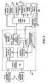
- FIG 4 illustrates a flow chart of a method performed by the system 10 during adaptive monitoring of the patient according to an embodiment of the present invention.
- the microprocessor 142 initially sets up system variables in its memory so that the variables are proper for operation (step 200). For instance, data relating to the threshold conditions for each physiological parameter are entered into the memory of the microprocessor 142 serving the monitor 100.
- pre-determined baseline information regarding arrhythmia such as the frequency and signal amplitude of electrocardiograms that would constitute a class 1 arrhythmic event are stored in the flash memory of the microprocessor 142. It is also within the scope of this invention to utilize algorithmic routines to calibrate non-static, non-preset thresholds that adapt to changing physical parameter base line information.
- the system is also set so that various types of system errors, malfunctions or low power level (hereinafter collectively referred to as "errors") are categorized as either urgent or non-urgent and this information is contained in the memory.
- errors system errors, malfunctions or low power level
- the microprocessor 142 runs an error routine to check for errors.
- an error that has occurred is "urgent” (e.g., hardware or software malfunction, system crash, corrupted data, or other error that requires the user to reinitialize the system or to obtain technical servicing of the module) or "non-urgent” (e.g., signal loss from one of the several electrode sensors due to detachment from the patient's body, warning that 24 hours of battery operating time remains, or static or electrical interference issues) that will need eventual, but not immediate patient attention.
- urgent e.g., hardware or software malfunction, system crash, corrupted data, or other error that requires the user to reinitialize the system or to obtain technical servicing of the module
- non-urgent e.g., signal loss from one of the several electrode sensors due to detachment from the patient's body, warning that 24 hours of battery operating time remains, or static or electrical interference issues
- the microprocessor 142 executes an initialization routine to prepare the monitor unit for operation (step 210). Part of the initialization routine is for the microprocessor 142 to perform power up tests of the monitor 100 and controls of the user interface 170, including the event button 104 and user display 106. If the system fails any of the power up tests, the microprocessor 142 idles and prompts status messages on the visual display through the user interface 170.
- the system enables a data acquisition mode (step 220).
- the system 10 receives and processes information from the electrode sensors 112 and continuously overwrites the ECG data in the CPU flash memory 144. Although it is within the scope of this invention to do so, to conserve memory and processing power, the activity data from the activity sensors 114 is not recorded.
- the data acquisition mode also includes receiving and processing information about the activity level of the patient output from the activity sensor 114. As described above, the output from the activity sensor 114 is processed through an activity threshold detector.
- the monitoring continues until signals from the electrode sensors exceed a pre-set threshold, and thus indicate a "cardiac event," (step 230).
- the microprocessor 142 determines whether the signals indicate a cardiac event of the type that is life-threatening regardless of the physical activity level of the patient, or of another type that is life-threatening only if physical activity level is below a pre-set threshold. For cardiac events that are inconsistent with normal physical activity on the part of the patient (e.g., cardiac event is of the type that should not trigger an alarm condition if it is detected while the patient is physically active), the microprocessor 142 processes the output of the activity threshold detector 148.
- the microprocessor 142 may suppress the cardiac event alert and return the system to the monitoring state 220. However, if in addition to exceeding the pre-set threshold for the electrode sensors, the activity level is below the set variable threshold (step 240), indicating that the patient is inactive, and has probably been rendered unconscious by the cardiac event, the microprocessor 142 does not suppress the cardiac event alert.
- the PMS may be programmed with additional pre-set thresholds that recognize a variety of ECG signals and patterns that indicate a cardiac event even when physical activity is detected on the part of the patient. In such instances, when ECG signals of a pre-determined type exceed the pre-set threshold, the cardiac event alerting will remain unsuppressed regardless of the patient's activity level.
- the microprocessor 142 When an unsuppressed cardiac event occurs, the microprocessor 142 records the time from clock 146, turns off the ECG data overwriting routine and saves ECG data relating to the cardiac event and a buffer time period before and after the event (e.g., 30 seconds before and 30 seconds after the event) in the flash memory of the microprocessor 142 for later transmission to an external monitoring device (not shown) and later study (step 250). It also signals the alarm circuit 160 to trigger the acoustic alarm 162 and sends a distress signal through the wireless transmitter 109 (step 260). The acoustic alarm continues to sound an alarm signal until it turned off by the patient or the doctor (step 270). If neither of the above events has occurred after a pre-set time interval of monitoring has occurred, the microprocessor 142 processes error routines (step 290).
- a buffer time period before and after the event e.g., 30 seconds before and 30 seconds after the event
- the microprocessor 142 processes error routines (step 290).
- the microprocessor 142 checks for system errors and malfunctions and conducts a test for the battery power level. If any type of system error is detected during the error routine, the microprocessor 142 determines, based on the information in the memory 144, whether the error is urgent or non-urgent (step 300). If it is urgent, the microprocessor 142 sends a signal to trigger the acoustic alarm 162 and wireless transmitter 109 (step 310). However, if a non-urgent error is detected, the microprocessor 142 processes the output of the activity threshold detector 148.
- the microprocessor 142 may sound an acoustic alarm 162 and wireless transmitter 109 to alert the patient to system malfunctions or errors requiring immediate attention.
- the microprocessor 142 triggers a silent alarm such as a visual message on the user display 106 (step 330).
- the system 10 is designed to continue to monitor the patient normally until the activity level rises above the activity threshold, in which case, the system triggers the acoustic alarm (step 260).
Abstract
Description
- The present invention relates generally to the field of physiological monitoring of patients, and more particularly, to methods and an apparatus for a physiological monitoring system with an adaptive alert mechanism.
- Doctors often need round-the-clock measurements of a body parameter over a period of time to make an accurate diagnosis of a condition. Vasovagal syncopal events and arrhythmias of the heart are particularly challenging to diagnose because of their relative infrequency, sudden onset and short duration. Holter monitors are one type of ambulatory physiological monitoring systems (PMS) that are used to measure the electrical signals of a patient's heart over a period of time to detect abnormalities in the heart beat of the patient. Typically, these systems continuously monitor electrocardiography (ECG) signals for a finite test period of about 24-96 hours. By reviewing the collected ECG data in an external monitoring device, doctors may identify patients who have heart arrhythmias and who are at risk for ventricular tachycardia or other cardiac conditions.
- In patients who have already been diagnosed with an arrhythmic heart condition, and who are at risk for potentially life-threatening cardiac events, it is often desired to monitor their condition over the long term. It is therefore desirable that the monitoring system be capable of long term monitoring for arrhythmic events and adequately capture such events when they occur. Since the device will be worn by the patient for potentially long durations of time, it is also desirable for the device to be compact, lightweight, mechanically robust, and unobtrusive as the patient goes about his normal daily routine of activity and rest. Traditional Holter monitors are unsuitable for such long term monitoring because of their bulky profile and relatively high power consumption levels required to power the continual ECG detection and data storage.
- Ambulatory ECG monitors typically include several electrodes that are attached to the patient and a processor that acquires and processes the electrical signals into data and stores the data for later analysis. If it is functioning properly, the monitoring system is able to detect and capture cardiac event data for later retrieval and analysis. In practice, however, it is often the case that the monitoring becomes interrupted because of battery-power loss, sensor detachment problems, or other system or user errors.
- Existing PMS typically employ an audible or visual alarm to alert the user of any such system malfunctions or errors. Some of the malfunctions or errors that trigger the alarm require immediate user attention, such as a malfunction requiring shutdown and restart of the PMS, signal loss due to improper sensor connection(s), or electrical interference. Other errors that trigger the alarm are less urgent (e.g., low battery power). In these prior art systems, both urgent and non-urgent types of information are communicated to the user via the alarm, whether or not the user is receptive to being disturbed.
- One such conventional system is described in
U.S. Patent No. 6,248,067 to Causey, Kovelman, Purvis, and Mastrototaro , and assigned to MiniMed Inc., which patent is entitled "Analyte Sensor and Holter-Type Monitor System and Method of Using the Same,".This patent describes a Holter-type recorder device equipped with a vibrator alarm or optical indicator such as a light-emitting diode (LED) that alerts the user of a system malfunction. This vibration alarm, if it remains unanswered by the user, provides additional reminders to an audio alarm. The drawback of this system is that the audio alarm may become triggered during periods of sleep or other inopportune times when the user cannot respond promptly. -
US-A-5 404 877 discloses an alarm capable of sensing impedance measurements of heart, respiratory and patient motion and, from these measurements, generating an alarm signal when the measurements indicate the occurrence of a cardiac arrhythmia. - In other systems, a user of the PMS may manually change a switch setting between audible and/or silent (e.g. tactile or visual) alarm modes to prevent undesired beeping interruptions. However, manual switching represents a suboptimal solution because the burden is on the user to constantly switch between modes as he goes about his daily routine of active and inactive periods and other instances where interruptions may not be tolerated or it is necessary to conceal the presence of the PMS.
- There is a need, therefore, for an improved method and apparatus for an adaptive physiological monitor that alerts the user of events indicating a system problem or malfunction when it determines that the user is in an active waking state or otherwise receptive of receiving and responding to the alarm.
- In the case of PMS systems that alarm for life-threatening arrhythmia conditions, physical activity on the part of the monitored patient has some additional implications. First, physical activity may result in signal artifact that causes the monitored physiological parameter (e.g. the ECG signal) to resemble its form when some life-threatening arrhythmias (e.g. ventricular fibrillation) are present when they are in fact absent, and may generate a false positive alarm. At the same time, physical activity above a certain level may be inconsistent with the presence of the life-threatening arrhythmia or condition, because the life-threatening condition weakens the patient or renders the patient unconscious. Thus, physical activity itself, apart from its influence on the signal quality of the monitored physiological parameter, provides significant information about the patient's
- cardiac status, and in combination with the ECG signals, provides a more complete assessment of the cardiac condition of a patient at a given time.
- Accordingly, there is also a need for a knowledge-based PMS that inhibits the transmission of an alarm reflecting a life-threatening physiological event when the system detects that the patient is physically active.
- The present invention solves these and other problems by providing a method according to claim 18 an apparatus according to claim 1.
- Preferred embodiments are defined in the dependent claims Detection of arrhythmia does not form part of the invention.
-
FIG 1 is a perspective view of one embodiment of the physiological monitoring system of the present invention. -
FIG 2 is a pictorial view showing a physiological monitoring system (PMS) according to an embodiment of the present invention on a patient. -
FIG 3 illustrates a block diagram depicting the major components of the PMS according to an exemplary embodiment of the present invention. -
FIG 4 is a flow chart depicting the steps performed by the physiological monitoring system to create a feedback loop that monitors a patient's physiological parameters and alerts the patient of system errors and physiological conditions in an adaptive manner based on the detected activity level of the patient. - A more complete understanding of the method and apparatus of the present invention is available by reference to the following detailed description of the embodiments when taken in conjunction with the accompanying drawings. It is worthy to note that any reference herein to "one embodiment" or "an embodiment" means that a particular feature, structure, or characteristic described in connection with the embodiment is included in at least one embodiment of the invention. The appearances of the phrase "in one embodiment" in various places in the specification are not necessarily all referring to the same embodiment. The detailed description of the embodiments which follows is intended to illustrate but not limit the invention. The scope of the invention is defined by the appended claims.
- A physiological monitoring system according to the present invention comprises an adaptive system that, in addition to monitoring a particular physical characteristic of the patient for medical purposes, communicates a variety of information to the user based on a knowledge-based approach that determines whether the user is physically active. If the system detects that the patient is asleep, resting, or otherwise in a non-active state, it defers the transmission of non-urgent information until it detects that the patient is in a normal active state. On the other hand, if the system detects that the patient is in a normal active state, it inhibits, as false alarms, transmission of any urgent information that is inconsistent with the patient being in a normal active state.
- Briefly, the above-described adaptive monitoring is achieved by way of an internal microprocessor having sufficient logic and data analysis capabilities to independently perform all internal control functions, including acquisition of data from sensors, processing of that data, and providing appropriate instructions to various sensors and output devices. On-board memory (e.g., static read and write memory) performs control and analysis processes and selectively stores critical information regarding a cardiac episode.
-
FIG 1 illustrates a perspective view of an embodiment of the monitoring system for monitoring cardiac parameters in an ambulatory setting of daily activity. Thesystem 10 comprises amonitor 100 andsensors 110 or other transducers that are connected to themonitor 100. Awireless transmitter 109, and optionally, anevent button 104 are located on themonitor 100. - The
monitor 100 is designed for use with one or more sensors or transducers such aselectrodes 112. As will be appreciated by one of skill in the art, a variety of sensors may be employed in the practice of this invention. With sufficient hardware and connections to the body, numerous physiologic parameters may be sensed as is pointed out inU.S. Pat. No. 5,464,434 issued to Alt andU.S. Pat. No. 5,464,431, issued to Adams et al. The physical parameters may include, but are not limited to, a patient's body movements, heartbeats, respiratory movements, snoring, and other mechanical movements and sounds detected by the sensors, respiration rate and depth (by for example, impedance plethysmography), brain waves, body temperature, and blood pressure. - A plurality of
sensors 110 may be employed simultaneously to measure the same or different physiological characteristics. For instance, typically two to sixelectrodes 112 may be employed to measure biological rhythmic signals such as heart rate in conjunction with anactivity sensor 114 such as an accelerometer that measures the physical activity level of the patient. As shown inFIG 2 , in one embodiment, at least one set ofsensors 110 comprisesECG electrodes 112 that measure electrocardiograms and that are placed in contact with the patient's body so as to receive signals from the patient which are transmitted to themonitor 100. As is obvious to one of skill in the art, the electrodes may be conventional electrodes comprised of silver chloride or other compositions designed to receive analog ECG input. Thesystem 10 may also comprise a set ofactivity sensors 114 that detect motion, movement, acceleration, mechanical vibrations, sound, or other indicator of physical activity on the part of the human subject. - The
activity sensor 114 may comprise a piezoelectric pressure transducer, a pedometer, a vibratory or motion detector, a detector that measures residual noise generated by friction between the electrode contacts and the patient's skin, strain gage or other transducer means for measuring activity. In addition to an accelerometer, other sensors which measure physiological parameters which distinguish between resting and active states may be employed. - In one mode of the invention, the
activity sensor 114 is a cantilevered suspended element which constitutes a high impedance voltage generator such as a piezoelectric element. The sensors may be incorporated into themonitor module 100 itself, or placed in close proximity to the monitor. The output of theactivity sensor 114 is connected to a processor 142 contained within themonitor 100. The piezoelectric element is a passive element or sensor requiring no power to cause it to be operational. The distortion of the surface of or of the element, itself, generates the appropriate signal. - The
activity sensors 114 may alternatively detect chemical or electrical changes in the patient that indicate the onset of sleep. For example, in one exemplary embodiment, theactivity sensor 114 is integrated within themonitor 100 unit, as shown inFIG 2 , and in other embodiments, are external to themonitor 100, such as a wrist-mountedactivity sensor 114 attached to a wrist with a strap that detects electromyographic (EMG) electrical impulses produced by the wearer's wrist muscles. Such electrical impulses provide measurements of the changes in the muscular activity at the wearer's wrist, which measurements are useful in detecting drowsiness. Thesensors 110 are applied to the body such that the surface of the sensors makes physical and/or electrical contact with the patient. - Although the
monitor 100, and thus thesensors 110 are shown applied to the chest, one of skill in the art will appreciate that various alternative sensor construction, materials, and designs are within the scope of the present invention. The information signals from these measuring devices such as theECG electrodes 112 andactivity sensors 114 are then transmitted to themonitor 100 for amplification and processing. - Referring now to
FIG 3 , which is a block diagram of the major elements of themonitoring system 10, the system includes the sensors 110 (sensor electrodes 112 and activity sensor 114), anelectronics module 140, apower circuit 150, which provides power to thesystem 10, and may include a voltage splitter and voltage regulator in addition to a battery, an alarm 160 (acoustic alarm 162 and silent alarm such as a tactile or visual/light alarm 164), auser interface module 170, awireless transmitter 109 or other means for communicating with an external computer, device, or medical personnel (not shown). Theuser interface module 170 includes anevent button 104 and optionally, auser display 106 which displays status messages and system error messages to the user. - Referring now to the details of the
exemplary electronics module 140 shown in block form inFIG 3 , the major components of theelectronic module 140 include a CPU or microprocessor 142 with aninternal CPU memory 144 and an internal digital input/output circuit,signal conditioners 145, analog-to-digital converters 147, anactivity threshold detector 148 input with aprogrammable activity level 149, and aclock 146. The microprocessor 142 performs a multitude of functions, including, but not limited to, receiving and processing signals output from thesensors 110 regarding arrhythmia conditions and checking and processing system errors. The selection and design of such circuitry and various other circuit means will be obvious to one of ordinary skill upon review of this specification. - The output of the
sensors 110 such as theECG electrodes 112 is coupled to asignal conditioning circuit 145 which filters and amplifies the output. For the purposes of this example, the present invention contemplates that theECG electrode sensors 112 andactivity sensor 114 are analog signals that are communicated to an analog-to-digital (A/D) converter and communicated to the microprocessor 40 as digital signals alongsignal path 141. Digital sensors may be substituted, bypassing the A/D converter 147. - Communication between the microprocessor 142 and memory/
storage 144 is provided bymemory line 143. The data storage (memory)device 144 is optionally included for storing the ECG signal data, pre-set threshold limits for the physiological conditions being monitored, and user input received through theuser interface module 170. - In the interest of keeping the
monitor 100 compact and lightweight, thememory 144 may be limited to internal CPU/microprocessor memory, which for example, may be static random access memory or "flash" memory, their equivalents, or any of the above in combination with conventional magnetic storage such as a small portable disk drive unit. If the memory comprises only an internal CPU flash memory with limited data storage capacity, the ECG signal data detected byelectrodes 112 may be stored into memory in a continuous overwrite mode. - In the present embodiment, flash memory (e.g., 128K of SRAM) is provided. Under normal circumstances when no arrhythmia event is occurring, the
monitoring system 10 continuously overwrites the ECG data in the CPU flash memory. When an arrhythmia event does occur, themonitoring system 10 retains the data for the short time period surrounding the event (e.g. 1 minute) in the memory for later study. As will be appreciated by one of skill, the information may be stored in reserved areas of a looping memory, preferably in identifiable memory partitions and accessed in sections or in its entirety with the appropriate external device to initiate and receive such transmissions from themonitoring system 10. Event recording using such a looping memory is detailed in the prior art such as inU.S. Patent No. 5,987,352 to Klein, Warkentin, Riff, Lee, Carney, Turi, and Varrichio , and assigned to Medtronic, Inc., which patent is entitled "Minimally Invasive Implantable Device for Monitoring Physiologic Events," - For each physiological parameter that is being monitored by the
sensors 110, an individualized baseline or threshold may be computed and stored in the RAM memory of the microprocessor 142 or an optionalexternal memory 144. In the case of some physiological parameters, fixed threshold levels may be used. The microprocessor 142 receives status information from thememory 144 regarding these system variables. In an exemplary embodiment, information regarding the arrhythmia frequency that is pre-determined to qualify as a class 1 arrhythmia event is stored in the flash memory of the microprocessor 142. If the ECG sensors measure electrical signals that exceed the programmed arrhythmia frequency, the microprocessor 142 alerts the patient through theuser interface module 170, and/or with external devices through thewireless transmitter 109. In the case of alerts reflecting states in which the patient may require assistance, or may be unresponsive, alerts may instead or additionally be directed, by means of wireless transmission to an external system, such as to an emergency responder. - The
user interface 170 communicates with the microprocessor 142 of theelectronics module 140 via an internal digital input/output circuit which communicates directly with the microprocessor 142 on input/output lines. For instance, when the battery power is low (e.g., depletion within 24 hours of usage), the microprocessor prompts a message on theuser display 106, warning the user that the battery power needs to be recharged. Theuser display 106 is a visual display that may be implemented as a light-emitting diode (LED) display, a dual-colored (back to back) LED, or a conventional alphanumeric display such as a liquid crystal display (LCD). In the single LED embodiment, the microprocessor may cause the LED to flash to indicate low battery power or a system error. In a dual-colored LED embodiment, the microprocessor 142 may cause the LED to remain unlit and flash in two different colors to indicate the status of the battery power or other system functions. If an LCD is employed, the display may indicate the time of day as well as system status information. - In some embodiments, the pressing of the
optional event button 104 by the ambulatory patient causes theuser interface 170 to send a signal to the microprocessor 142 to trigger theacoustic alarm 162 which emits an audible alarm and optionally transmits an alarm signal to a wired or wireless transceiver or other external communication device (not shown) for contacting appropriate medical personnel. In addition, actuation of theevent button 104 may cause the microprocessor 142 to record the time an event such as the suffering of chest pains or heart flutters occurred so that the ECG data recorded at that time can be flagged for closer examination. Pressing theevent button 104 also causes the microprocessor 142 to store the ECG data sequence of the event in the flash memory of the microprocessor 142 for later transmission to an external monitoring device (not shown) and later study. In the event of a false alarm, theoptional event button 104 may also be used to contact and to cancel the emergency help. - The
acoustic alarm 162 also emits an acoustic signal when an observed cardiovascular activity or other physiological parameter surpasses a preset limit (e.g., surpassing the maximum number of arrhythmias preset by the doctor will generate an alarm). In the case of a physiological state that is inconsistent with normal physical activity on the part of the patient, if the activity monitor threshold is exceeded, such an alert may be suppressed as a false alarm. - The output of the sensors 110 (
electrode sensors 112 and activity sensor 114) is coupled to asignal conditioning circuit 145, which amplifies and filters the signals, and converted to a digital format by the analog/digital converter. The signals from theactivity sensor 114, once digitally processed, are input into anactivity threshold detector 148, which is coupled to the A/D converter 147. The flow of signals andactivity threshold detector 148 are set to a selected activity level byprogrammable activity level 149. Theactivity threshold detector 148 is connected to a control circuit in the microprocessor 142. The output ofactivity threshold detector 148 may be in binary form. For example, it may be a binary 1 if a threshold level of activity is sensed and a binary 0 if less than the threshold level of activity is sensed. The binary signal is fed to the control circuit of the microprocessor 142, which operates to power thealarm system 160. Multiple activity thresholds may be employed, establishing separate control levels for the separate adaptive functions of controlling non-urgent communication and urgent communication. -
FIG 4 illustrates a flow chart of a method performed by thesystem 10 during adaptive monitoring of the patient according to an embodiment of the present invention. The microprocessor 142 initially sets up system variables in its memory so that the variables are proper for operation (step 200). For instance, data relating to the threshold conditions for each physiological parameter are entered into the memory of the microprocessor 142 serving themonitor 100. Thus, pre-determined baseline information regarding arrhythmia, such as the frequency and signal amplitude of electrocardiograms that would constitute a class 1 arrhythmic event are stored in the flash memory of the microprocessor 142. It is also within the scope of this invention to utilize algorithmic routines to calibrate non-static, non-preset thresholds that adapt to changing physical parameter base line information. - The system is also set so that various types of system errors, malfunctions or low power level (hereinafter collectively referred to as "errors") are categorized as either urgent or non-urgent and this information is contained in the memory. In an exemplary embodiment of the
physiological monitoring system 10 of the present invention, the microprocessor 142 runs an error routine to check for errors. Based on pre-set information, it recognizes whether an error that has occurred is "urgent" (e.g., hardware or software malfunction, system crash, corrupted data, or other error that requires the user to reinitialize the system or to obtain technical servicing of the module) or "non-urgent" (e.g., signal loss from one of the several electrode sensors due to detachment from the patient's body, warning that 24 hours of battery operating time remains, or static or electrical interference issues) that will need eventual, but not immediate patient attention. - When the
monitor 100 is powered up, the microprocessor 142 executes an initialization routine to prepare the monitor unit for operation (step 210). Part of the initialization routine is for the microprocessor 142 to perform power up tests of themonitor 100 and controls of theuser interface 170, including theevent button 104 anduser display 106. If the system fails any of the power up tests, the microprocessor 142 idles and prompts status messages on the visual display through theuser interface 170. - If the system checks were successfully completed, the system enables a data acquisition mode (step 220). During the data acquisition mode, the
system 10 receives and processes information from theelectrode sensors 112 and continuously overwrites the ECG data in theCPU flash memory 144. Although it is within the scope of this invention to do so, to conserve memory and processing power, the activity data from theactivity sensors 114 is not recorded. The data acquisition mode also includes receiving and processing information about the activity level of the patient output from theactivity sensor 114. As described above, the output from theactivity sensor 114 is processed through an activity threshold detector. - The monitoring continues until signals from the electrode sensors exceed a pre-set threshold, and thus indicate a "cardiac event," (step 230). The microprocessor 142 determines whether the signals indicate a cardiac event of the type that is life-threatening regardless of the physical activity level of the patient, or of another type that is life-threatening only if physical activity level is below a pre-set threshold. For cardiac events that are inconsistent with normal physical activity on the part of the patient (e.g., cardiac event is of the type that should not trigger an alarm condition if it is detected while the patient is physically active), the microprocessor 142 processes the output of the
activity threshold detector 148. - If the microprocessor 142 determines that the measured signal level is above a pre-programmed activity threshold for a predetermined period of time (which may be medically and experimentally determined), indicating that the patient is in an alert state, the microprocessor 142 may suppress the cardiac event alert and return the system to the
monitoring state 220. However, if in addition to exceeding the pre-set threshold for the electrode sensors, the activity level is below the set variable threshold (step 240), indicating that the patient is inactive, and has probably been rendered unconscious by the cardiac event, the microprocessor 142 does not suppress the cardiac event alert. - In certain embodiments of the invention, the PMS may be programmed with additional pre-set thresholds that recognize a variety of ECG signals and patterns that indicate a cardiac event even when physical activity is detected on the part of the patient. In such instances, when ECG signals of a pre-determined type exceed the pre-set threshold, the cardiac event alerting will remain unsuppressed regardless of the patient's activity level.
- When an unsuppressed cardiac event occurs, the microprocessor 142 records the time from
clock 146, turns off the ECG data overwriting routine and saves ECG data relating to the cardiac event and a buffer time period before and after the event (e.g., 30 seconds before and 30 seconds after the event) in the flash memory of the microprocessor 142 for later transmission to an external monitoring device (not shown) and later study (step 250). It also signals thealarm circuit 160 to trigger theacoustic alarm 162 and sends a distress signal through the wireless transmitter 109 (step 260). The acoustic alarm continues to sound an alarm signal until it turned off by the patient or the doctor (step 270). If neither of the above events has occurred after a pre-set time interval of monitoring has occurred, the microprocessor 142 processes error routines (step 290). - At
step 290, the microprocessor 142 checks for system errors and malfunctions and conducts a test for the battery power level. If any type of system error is detected during the error routine, the microprocessor 142 determines, based on the information in thememory 144, whether the error is urgent or non-urgent (step 300). If it is urgent, the microprocessor 142 sends a signal to trigger theacoustic alarm 162 and wireless transmitter 109 (step 310). However, if a non-urgent error is detected, the microprocessor 142 processes the output of theactivity threshold detector 148. - If the microprocessor 142 determines that the measured signal level is above a pre-programmed activity threshold for a predetermined period of time (which may be medically and experimentally determined), indicating that the patient is in an alert state, the microprocessor 142 may sound an
acoustic alarm 162 andwireless transmitter 109 to alert the patient to system malfunctions or errors requiring immediate attention. However, if the activity level drops below the set variable threshold (step 320), indicating that the patient is asleep or resting, the microprocessor 142 triggers a silent alarm such as a visual message on the user display 106 (step 330). Thesystem 10 is designed to continue to monitor the patient normally until the activity level rises above the activity threshold, in which case, the system triggers the acoustic alarm (step 260). - Although various embodiments are specifically illustrated and described herein, it will be appreciated that modifications and variations are possible without departing from the scope of the invention. For example, specific electrodes for the monitoring system are depicted herein, yet other sensors are possible without departing from the scope of the present invention. Substitute sensors that detect physiological characteristics that function similarly to electrodes will be obvious to one of ordinary skill in the art. Moreover, while three electrodes are shown, other numbers of electrodes can be used without departing from the scope of the present invention. Furthermore, these examples should not be interpreted to limit the modifications and variations of the invention covered by the claims but are merely illustrative of possible variations.
Claims (21)
- A physiological monitoring system (10) which comprises:at least one sensor for detecting a biological signal (112), representative of a physiological characteristic of a monitor-wearing patient and generating an electrical signal representative of the biological signal;at least one sensor for detecting the physical activity of the patient (114) andgenerating an electrical signal, representative of physical activity;processing means (142), coupled to said sensors (112, 114) for processing said electrical signals;an activity threshold detector (148) coupled to said processing means (142) for receiving said electrical signals representative of physical activity;means for testing system functions;a user interface (170) for communicating information about the detected biological signal and system functions to the patient;means for delaying or inhibiting the communication of information (109) in response to detection of an activity threshold by said activity threshold detector (148).
- The system of claim 1, further comprising a means for programming said physical activity sensor 114 for operational control at a selected threshold of physical activity.
- The system of claim 1, wherein the physiological characteristic sensor (112) is adapted to sense cardiac signals.
- The system of claim 1, wherein the physiological characteristic sensor (112) comprises electrocardiography electrodes that detect biological signals representative of the heart beats of the patient.
- The system of claim 1, wherein the physical activity sensor (114) comprises a transducer that detects chemical, electrical or mechanical characteristics of a monitor-wearing patient, representative of physical activity, including vibrations, motion, acceleration, electromyographic impulses, or sound impulses.
- The system of claim 1, wherein the physical activity sensor (114) comprises an accelerometer, a pedometer, an electrical noise detector, electronic capacitive sensor, an electromyographic sensor, a skin impedance sensor, or a piezoelectric sensor.
- The system of claim 1, wherein the physical activity sensor (114) is a passive transducer including a piezeoelectric element.
- The system of claim 1, further comprising a means for wireless transmission of information (109) about the detected biological signal or system functions to a receiver external to the system.
- The system of claim 1 adapted for recording electrocardiography signals from a patient, wherein said at least one sensor is
a plurality of sensors (110) for detecting a plurality of biological signals, each biological signal representative of a physiological characteristic of a monitor-wearing patient, wherein at least one sensor (110) comprises one or more electrocardiography electrodes (112) that sense electrocardiography signals from a patient , whereby the sensors generate an electrical signal representative of each respective biological signal;
wherein the system further comprises :an arrhythmia threshold detector (142) coupled to the electrocardiography electrodes (112) for receiving said electrical signals representative of the electrocardiography signals and determining whether the signals are below or above a preset threshold;wherein the activity threshold detector(148) is coupled to the activity sensor (114) for receiving said electrical signals representative of the activity level of the patient and determining whether the signals are below or above a predetermined threshold;system error detector (142) for detecting system errors, including signal loss, electrode detachment from patient, low battery power, corrupted data, or electrical interference and determining if the detected error meets pre-determined criteria;processor (142) for delaying or inhibiting the communication of system and biological signal information to the patient through a user interface (170) based on the detection of an activity threshold by said activity threshold detector (148), arrhythmia threshold by said arrhythmia threshold detector (142), and/or system errors by the system error detector (142). - The system of claim 9, wherein the user interface (170) comprises an alarm circuit (160) comprising acoustic, tactile, or visual modes of communicating information to the patient, and mode is determined by processor (142) based on whether the signals from the respective detectors (142, 148) meet pre-determined thresholds.
- The system of claim 9, wherein processor (142) further comprises a calibration means for setting the threshold of the arrhythmia threshold detector (142) based on processing of electrocardiography signals from the patient to generate a baseline of electrocardiography information.
- The system of claim 9, wherein the threshold of the arrhythmia threshold detector (142) is pre-programmed into a memory component (142, 144) of the system (10).
- The system of claim 9, wherein the physical activity sensor (114) comprises a transducer that detects chemical, electrical or mechanical characteristics of a monitor-wearing patient, representative of physical activity, including vibrations, motion, acceleration, electromyographic impulses, or sound impulses.
- The system of claim 9, wherein the physical activity sensor (114) comprises an accelerometer, a pedometer, an electrical noise detector, electronic capacitive sensor, an electromyographic sensor, a skin impedance sensor, or a piezoelectric sensor.
- The system of claim 9, wherein the physical activity sensor (114) is a passive transducer including a piezeoelectric element.
- The system of claim 9, wherein the arrhythmia threshold detector (142) is set at a pre-determined threshold to detect the occurrence of class 1 arrhythmia event.
- The system of claim 9, further comprising means of wireless communication (109) to an external system, for communication of information about the patient and system state to the patient or to others.
- A method for communicating information about a patient during ambulatory monitoring of a physiological condition of the patient comprising the steps of:attaching a physiological monitoring system (10) to a patient;sensing one or more selected physiological parameters of the patient;sensing the physical activity of the patient;comparing the sensed physical activity to a pre-set threshold to determine whether the patient is in an inactive state or in an active state;detecting a system error to be communicated to the patient and determining whether the detected error meets pre-determined criteria;generating an error signal based on the system error and transmitting the error signal to the patient via a user interface (170), if the patient is in the active state.
- The method of claim 18, wherein the physiological monitoring system (10) comprises a physical activity sensor (114) comprising a transducer that detects pre-determined chemical, electrical or mechanical characteristics of a monitor-wearing patient that are representative of physical activity, wherein the characteristics comprise vibrations, motion, acceleration, electromyographic impulses, or sound impulses.
- The method of claim 18, wherein the physiological monitoring system (10) comprises a physical activity sensor (114) comprising an accelerometer, a pedometer, a noise detector, electronic capacitive sensor, an electromyographic sensor, or a piezoelectric sensor.
- The method of claim 18, wherein the selected physiological parameter of the patient is sensed by at least one sensor (110) comprising two or more electrocardiography electrodes (112) that sense electrocardiography signals from the patient, whereby the sensor (110) generates an electrical signal representative of the selected physiological parameter.
Applications Claiming Priority (2)
| Application Number | Priority Date | Filing Date | Title |
|---|---|---|---|
| US53676304P | 2004-01-15 | 2004-01-15 | |
| PCT/IB2005/050056 WO2005070289A1 (en) | 2004-01-15 | 2005-01-05 | Adaptive physiological monitoring system and methods of using the same |
Publications (2)
| Publication Number | Publication Date |
|---|---|
| EP1708613A1 EP1708613A1 (en) | 2006-10-11 |
| EP1708613B1 true EP1708613B1 (en) | 2011-12-14 |
Family
ID=34807048
Family Applications (1)
| Application Number | Title | Priority Date | Filing Date |
|---|---|---|---|
| EP05702586A Active EP1708613B1 (en) | 2004-01-15 | 2005-01-05 | Adaptive physiological monitoring system and methods of using the same |
Country Status (6)
| Country | Link |
|---|---|
| US (1) | US20070167850A1 (en) |
| EP (1) | EP1708613B1 (en) |
| JP (1) | JP5094125B2 (en) |
| CN (1) | CN100553555C (en) |
| AT (1) | ATE536801T1 (en) |
| WO (1) | WO2005070289A1 (en) |
Cited By (2)
| Publication number | Priority date | Publication date | Assignee | Title |
|---|---|---|---|---|
| CN102846317A (en) * | 2012-07-18 | 2013-01-02 | 上海交通大学 | Wearing-type electromyographic signal acquisition system |
| US11389063B2 (en) | 2017-11-20 | 2022-07-19 | Welch Allyn, Inc. | Modular vital signs monitor |
Families Citing this family (152)
| Publication number | Priority date | Publication date | Assignee | Title |
|---|---|---|---|---|
| US7545272B2 (en) | 2005-02-08 | 2009-06-09 | Therasense, Inc. | RF tag on test strips, test strip vials and boxes |
| CN101322128A (en) * | 2005-10-06 | 2008-12-10 | 沃根斯娱乐有限责任公司(加利福尼亚州有限责任公司) | Substantially simultaneous alerts and use thereof in intermittent contests |
| CN101321495A (en) * | 2005-12-08 | 2008-12-10 | 皇家飞利浦电子股份有限公司 | Medical sensor having electrodes and a motion sensor |
| RU2435521C2 (en) | 2005-12-15 | 2011-12-10 | Конинклейке Филипс Электроникс Н.В. | Method of detecting and compensation for control of activity point on body |
| CN103368792B (en) * | 2006-05-16 | 2017-04-12 | 皇家飞利浦电子股份有限公司 | Communication system for monitoring the health status of a patient, communication device, sensor device and method |
| US9962098B2 (en) | 2006-06-02 | 2018-05-08 | Global Cardiac Monitors, Inc. | Heart monitor electrode system |
| US8157730B2 (en) | 2006-12-19 | 2012-04-17 | Valencell, Inc. | Physiological and environmental monitoring systems and methods |
| US8652040B2 (en) | 2006-12-19 | 2014-02-18 | Valencell, Inc. | Telemetric apparatus for health and environmental monitoring |
| FI20065828L (en) | 2006-12-20 | 2008-06-21 | Polar Electro Oy | Portable electronic device, method and computer program product |
| CN101108125B (en) * | 2007-08-02 | 2010-06-16 | 无锡微感科技有限公司 | Dynamic monitoring system of body sign |
| WO2009036348A1 (en) | 2007-09-14 | 2009-03-19 | Corventis, Inc. | Medical device automatic start-up upon contact to patient tissue |
| EP2200499B1 (en) | 2007-09-14 | 2019-05-01 | Medtronic Monitoring, Inc. | Multi-sensor patient monitor to detect impending cardiac decompensation |
| US9186089B2 (en) | 2007-09-14 | 2015-11-17 | Medtronic Monitoring, Inc. | Injectable physiological monitoring system |
| EP3922171A1 (en) | 2007-09-14 | 2021-12-15 | Medtronic Monitoring, Inc. | Adherent cardiac monitor with advanced sensing capabilities |
| US20090076343A1 (en) | 2007-09-14 | 2009-03-19 | Corventis, Inc. | Energy Management for Adherent Patient Monitor |
| US8249686B2 (en) | 2007-09-14 | 2012-08-21 | Corventis, Inc. | Adherent device for sleep disordered breathing |
| WO2009036313A1 (en) | 2007-09-14 | 2009-03-19 | Corventis, Inc. | Adherent device with multiple physiological sensors |
| US9949641B2 (en) | 2007-10-19 | 2018-04-24 | Smiths Medical Asd, Inc. | Method for establishing a telecommunications system for patient monitoring |
| US9986911B2 (en) | 2007-10-19 | 2018-06-05 | Smiths Medical Asd, Inc. | Wireless telecommunications system adaptable for patient monitoring |
| US8251903B2 (en) | 2007-10-25 | 2012-08-28 | Valencell, Inc. | Noninvasive physiological analysis using excitation-sensor modules and related devices and methods |
| CN101430817B (en) * | 2007-11-08 | 2011-09-07 | 深圳迈瑞生物医疗电子股份有限公司 | Alarm triggering method and device according to human body rhythmic physiological parameter |
| US8290574B2 (en) * | 2008-03-10 | 2012-10-16 | Koninklijke Philips Electronics N.V. | ECG monitoring system with configurable alarm limits |
| WO2009114548A1 (en) | 2008-03-12 | 2009-09-17 | Corventis, Inc. | Heart failure decompensation prediction based on cardiac rhythm |
| US20090247850A1 (en) * | 2008-03-28 | 2009-10-01 | Nellcor Puritan Bennett Llc | Manually Powered Oximeter |
| US8412317B2 (en) | 2008-04-18 | 2013-04-02 | Corventis, Inc. | Method and apparatus to measure bioelectric impedance of patient tissue |
| DE102008029173B4 (en) * | 2008-06-19 | 2015-01-15 | Siemens Aktiengesellschaft | Method for checking ECG signals measured with an ECG measuring device comprising at least three electrodes for the presence of a disorder and ECG measuring device |
| GB0812681D0 (en) * | 2008-07-10 | 2008-08-20 | Sec Dep For Innovation Universities | Apparatus and methods for effecting chemical assays |
| US8805482B2 (en) | 2008-07-28 | 2014-08-12 | General Electric Conpany | System and method for signal quality indication and false alarm reduction in ECG monitoring systems |
| US20100042012A1 (en) * | 2008-08-15 | 2010-02-18 | Karim Alhussiny | Diagnostic device for remote sensing and transmitting biophysiological signals |
| US20150201858A1 (en) * | 2008-08-15 | 2015-07-23 | Global Cardiac Monitors, Inc. | Diagnostic device for remote sensing and transmitting biophysiological signals |
| EP2375968B1 (en) * | 2008-12-15 | 2018-11-14 | Medtronic Monitoring, Inc. | Patient monitoring systems and methods |
| US8788002B2 (en) | 2009-02-25 | 2014-07-22 | Valencell, Inc. | Light-guiding devices and monitoring devices incorporating same |
| US9750462B2 (en) | 2009-02-25 | 2017-09-05 | Valencell, Inc. | Monitoring apparatus and methods for measuring physiological and/or environmental conditions |
| EP2400884B1 (en) | 2009-02-25 | 2018-03-07 | Valencell, Inc. | Light-guiding devices and monitoring devices incorporating same |
| FR2943447A1 (en) * | 2009-03-17 | 2010-09-24 | Denis Reynaud | Person's e.g. aged person, health status monitoring system, has alert circuit formed of management module and buffer memory unit providing alert information in direction of server center based on health parameters |
| US9492092B2 (en) * | 2009-05-20 | 2016-11-15 | Sotera Wireless, Inc. | Method for continuously monitoring a patient using a body-worn device and associated system for alarms/alerts |
| EP4231307A1 (en) * | 2009-05-29 | 2023-08-23 | University Of Virginia Patent Foundation | System coordinator and modular architecture for open-loop and closed-loop control of diabetes |
| JP5589594B2 (en) | 2009-06-29 | 2014-09-17 | ソニー株式会社 | Biological signal measuring device |
| JP5589593B2 (en) | 2009-06-29 | 2014-09-17 | ソニー株式会社 | Biological signal measuring device |
| US9554739B2 (en) | 2009-09-29 | 2017-01-31 | Covidien Lp | Smart cable for coupling a medical sensor to an electronic patient monitor |
| US20110082711A1 (en) | 2009-10-06 | 2011-04-07 | Masimo Laboratories, Inc. | Personal digital assistant or organizer for monitoring glucose levels |
| US8790259B2 (en) | 2009-10-22 | 2014-07-29 | Corventis, Inc. | Method and apparatus for remote detection and monitoring of functional chronotropic incompetence |
| US8838217B2 (en) | 2009-11-10 | 2014-09-16 | Makor Issues And Rights Ltd. | System and apparatus for providing diagnosis and personalized abnormalities alerts and for providing adaptive responses in clinical trials |
| US20110137135A1 (en) * | 2009-12-09 | 2011-06-09 | Mcgrath Michael J | Context Aware Physiological Monitoring |
| US9451897B2 (en) | 2009-12-14 | 2016-09-27 | Medtronic Monitoring, Inc. | Body adherent patch with electronics for physiologic monitoring |
| WO2011076243A1 (en) | 2009-12-21 | 2011-06-30 | Fundacion Fatronik | Affective well-being supervision system and method |
| US9078610B2 (en) * | 2010-02-22 | 2015-07-14 | Covidien Lp | Motion energy harvesting with wireless sensors |
| US8554517B2 (en) * | 2010-02-25 | 2013-10-08 | Sharp Laboratories Of America, Inc. | Physiological signal quality classification for ambulatory monitoring |
| US8965498B2 (en) | 2010-04-05 | 2015-02-24 | Corventis, Inc. | Method and apparatus for personalized physiologic parameters |
| US20110298621A1 (en) * | 2010-06-02 | 2011-12-08 | Lokesh Shanbhag | System and method for generating alerts |
| JP5722574B2 (en) * | 2010-08-27 | 2015-05-20 | 株式会社パラマ・テック | ECG system |
| CN102028459B (en) * | 2010-12-02 | 2013-01-02 | 广东宝莱特医用科技股份有限公司 | Channel pace-making signal detection method of electrocardiogram machine |
| US8665096B2 (en) * | 2010-12-21 | 2014-03-04 | General Electric Company | Alarm control method, physiological monitoring apparatus, and computer program product for a physiological monitoring apparatus |
| CN102551685B (en) * | 2010-12-30 | 2015-04-01 | 世意法(北京)半导体研发有限责任公司 | Object monitor |
| US8888701B2 (en) | 2011-01-27 | 2014-11-18 | Valencell, Inc. | Apparatus and methods for monitoring physiological data during environmental interference |
| WO2013016007A2 (en) | 2011-07-25 | 2013-01-31 | Valencell, Inc. | Apparatus and methods for estimating time-state physiological parameters |
| WO2013019494A2 (en) | 2011-08-02 | 2013-02-07 | Valencell, Inc. | Systems and methods for variable filter adjustment by heart rate metric feedback |
| US20130222137A1 (en) * | 2012-02-29 | 2013-08-29 | Motorola Mobility, Inc. | Method for adapting a mobile communication device's function to monitored activity and a user's profile |
| US9107571B2 (en) | 2012-04-24 | 2015-08-18 | Cardimetrix, Llc | ECG acquisition and treatment-response system for treating abnormal cardiac function |
| US10304347B2 (en) | 2012-05-09 | 2019-05-28 | Apple Inc. | Exercised-based watch face and complications |
| US10413251B2 (en) | 2012-10-07 | 2019-09-17 | Rhythm Diagnostic Systems, Inc. | Wearable cardiac monitor |
| US10244949B2 (en) | 2012-10-07 | 2019-04-02 | Rhythm Diagnostic Systems, Inc. | Health monitoring systems and methods |
| USD850626S1 (en) * | 2013-03-15 | 2019-06-04 | Rhythm Diagnostic Systems, Inc. | Health monitoring apparatuses |
| US10610159B2 (en) | 2012-10-07 | 2020-04-07 | Rhythm Diagnostic Systems, Inc. | Health monitoring systems and methods |
| TWI586318B (en) * | 2012-10-16 | 2017-06-11 | 長庚大學 | Integrated biological information sensing device |
| KR101911218B1 (en) | 2012-10-30 | 2018-10-24 | 삼성전자주식회사 | Method and apparatus for calculating amount of exercise |
| EP2934301B1 (en) | 2012-12-19 | 2020-04-22 | Elwha LLC | Controlling acquisition of sensor information |
| US9375145B2 (en) * | 2012-12-19 | 2016-06-28 | Elwha Llc | Systems and methods for controlling acquisition of sensor information |
| US10141073B2 (en) | 2012-12-19 | 2018-11-27 | Elwha Llc | Systems and methods for controlling acquisition of sensor information |
| KR20140089897A (en) * | 2013-01-08 | 2014-07-16 | 삼성전자주식회사 | Device and method for monitoring bio signal with low power |
| EP2931125A4 (en) | 2013-01-28 | 2015-11-11 | Valencell Inc | Physiological monitoring devices having sensing elements decoupled from body motion |
| US9855110B2 (en) * | 2013-02-05 | 2018-01-02 | Q-Core Medical Ltd. | Methods, apparatus and systems for operating a medical device including an accelerometer |
| US20140236530A1 (en) * | 2013-02-15 | 2014-08-21 | SQORD Inc. | Systems and methods for measuring and rewarding activity levels |
| CN103445766B (en) * | 2013-05-09 | 2016-01-20 | 陈飞 | The state monitoring method contrasted based on history physiological data and physical data and device |
| WO2014186606A1 (en) * | 2013-05-15 | 2014-11-20 | Zephyr Technology Corporation | Physiological monitoring and alerting |
| WO2014205546A1 (en) * | 2013-06-24 | 2014-12-31 | 2340960 Ontario Inc. | Wireless cardiac event recorder |
| USD744109S1 (en) * | 2013-09-25 | 2015-11-24 | Kabushiki Kaisha Toshiba | Biomedical signal recorder with a radio function |
| CN103654742A (en) * | 2013-12-04 | 2014-03-26 | 江南大学 | Multi-parameter identification system for monitoring human health conditions |
| EP3079571A4 (en) | 2013-12-12 | 2017-08-02 | Alivecor, Inc. | Methods and systems for arrhythmia tracking and scoring |
| USD777331S1 (en) * | 2014-05-01 | 2017-01-24 | MAD Apparel, Inc. | Electronic module |
| US10313506B2 (en) | 2014-05-30 | 2019-06-04 | Apple Inc. | Wellness aggregator |
| EP2960665B1 (en) * | 2014-06-27 | 2017-05-24 | Secure-IC SAS | Device and method for calibrating a digital sensor |
| US20160029898A1 (en) | 2014-07-30 | 2016-02-04 | Valencell, Inc. | Physiological Monitoring Devices and Methods Using Optical Sensors |
| EP3199100A1 (en) | 2014-08-06 | 2017-08-02 | Valencell, Inc. | Earbud with a physiological information sensor module |
| CN117038008A (en) * | 2014-09-02 | 2023-11-10 | 苹果公司 | Physical activity and fitness monitor |
| WO2016036114A1 (en) | 2014-09-03 | 2016-03-10 | Samsung Electronics Co., Ltd. | Electronic device and method for measuring vital signal |
| KR20170057313A (en) | 2014-09-09 | 2017-05-24 | 토르벡 인코포레이티드 | Methods and apparatus for monitoring alertness of an individual utilizing a wearable device and providing notification |
| US9668700B2 (en) | 2014-09-09 | 2017-06-06 | Heartflow, Inc. | Method and system for quantifying limitations in coronary artery blood flow during physical activity in patients with coronary artery disease |
| US9794653B2 (en) | 2014-09-27 | 2017-10-17 | Valencell, Inc. | Methods and apparatus for improving signal quality in wearable biometric monitoring devices |
| US10776739B2 (en) | 2014-09-30 | 2020-09-15 | Apple Inc. | Fitness challenge E-awards |
| US10342485B2 (en) * | 2014-10-01 | 2019-07-09 | Covidien Lp | Removable base for wearable medical monitor |
| TWI582727B (en) * | 2015-08-18 | 2017-05-11 | 國立交通大學 | Adaptive parameter prediction method and device for physiological reaction |
| EP4321088A3 (en) | 2015-08-20 | 2024-04-24 | Apple Inc. | Exercise-based watch face |
| WO2017040700A2 (en) | 2015-08-31 | 2017-03-09 | Masimo Corporation | Wireless patient monitoring systems and methods |
| US11272864B2 (en) * | 2015-09-14 | 2022-03-15 | Health Care Originals, Inc. | Respiratory disease monitoring wearable apparatus |
| CN108289613B (en) * | 2015-10-22 | 2021-07-06 | 泰拓卡尔有限公司 | System, method and computer program product for physiological monitoring |
| WO2017070463A1 (en) | 2015-10-23 | 2017-04-27 | Valencell, Inc. | Physiological monitoring devices and methods that identify subject activity type |
| US10945618B2 (en) | 2015-10-23 | 2021-03-16 | Valencell, Inc. | Physiological monitoring devices and methods for noise reduction in physiological signals based on subject activity type |
| WO2017079580A1 (en) * | 2015-11-06 | 2017-05-11 | Lifeq Global Limited | Energy efficient system and method for physiological monitoring |
| CN105469544A (en) * | 2015-11-19 | 2016-04-06 | 常州大学 | Hand-myoelectricity-based multi-functional walking stick |
| CN105534527B (en) * | 2015-12-01 | 2018-07-13 | 深圳还是威健康科技有限公司 | The recognition methods of intelligent wearable device special state and intelligent wearable device |
| US10321823B2 (en) * | 2015-12-21 | 2019-06-18 | Medtronic Monitoring, Inc. | System and method to flag arrhythmia episodes for urgent review |
| US9883800B2 (en) | 2016-02-11 | 2018-02-06 | General Electric Company | Wireless patient monitoring system and method |
| US9814388B2 (en) | 2016-02-11 | 2017-11-14 | General Electric Company | Wireless patient monitoring system and method |
| JP2019510550A (en) | 2016-02-18 | 2019-04-18 | カーイージス テクノロジーズ,インコーポレイティド | Attention prediction system and method |
| JP6938710B2 (en) * | 2016-02-26 | 2021-09-22 | フクダ電子株式会社 | Biometric information monitoring system and biometric information monitor |
| JP6938711B2 (en) * | 2016-02-26 | 2021-09-22 | フクダ電子株式会社 | Biometric information monitoring system and biometric information monitor |
| CN105796092A (en) * | 2016-03-09 | 2016-07-27 | 佛山市黑盒子科技有限公司 | Dynamic electrocardiograph continuous monitoring method of wearable device |
| CN107193019A (en) * | 2016-03-15 | 2017-09-22 | 手持产品公司 | In personal localizer beacon user biological measuring parameter is monitored using nanometer technology |
| CN108882853B (en) * | 2016-03-22 | 2021-11-09 | 皇家飞利浦有限公司 | Triggering measurement of physiological parameters in time using visual context |
| JP6732188B2 (en) * | 2016-03-22 | 2020-07-29 | 国立大学法人秋田大学 | Biometric sensor |
| JP6793287B2 (en) * | 2016-03-22 | 2020-12-02 | 国立大学法人秋田大学 | Biological signal measuring device and biological signal measuring method |
| CN105852826B (en) * | 2016-03-22 | 2018-10-09 | 北京奇虎科技有限公司 | The method that terminal and terminal determine physiologic information |
| US10098558B2 (en) | 2016-04-25 | 2018-10-16 | General Electric Company | Wireless patient monitoring system and method |
| JP6857367B2 (en) * | 2016-06-08 | 2021-04-14 | 国立大学法人 東京医科歯科大学 | Muscle activity measuring device and muscle activity measuring method |
| AU2017100667A4 (en) | 2016-06-11 | 2017-07-06 | Apple Inc. | Activity and workout updates |
| US11216119B2 (en) | 2016-06-12 | 2022-01-04 | Apple Inc. | Displaying a predetermined view of an application |
| US10298282B2 (en) * | 2016-06-16 | 2019-05-21 | Intel Corporation | Multi-modal sensing wearable device for physiological context measurement |
| WO2018009736A1 (en) | 2016-07-08 | 2018-01-11 | Valencell, Inc. | Motion-dependent averaging for physiological metric estimating systems and methods |
| CN106264506A (en) * | 2016-08-03 | 2017-01-04 | 深圳市科格微电子有限公司 | A kind of New infant device monitoring method and system |
| IT201600094345A1 (en) * | 2016-09-20 | 2018-03-20 | Massimiliano Garruzzo | Monitoring system of the physical conditions of at least one user and Method for monitoring the physical conditions of a user |
| US10736543B2 (en) | 2016-09-22 | 2020-08-11 | Apple Inc. | Workout monitor interface |
| USD842481S1 (en) | 2017-01-20 | 2019-03-05 | MAD Apparel, Inc. | Electronic module |
| US10845955B2 (en) | 2017-05-15 | 2020-11-24 | Apple Inc. | Displaying a scrollable list of affordances associated with physical activities |
| US10462281B2 (en) * | 2017-06-30 | 2019-10-29 | Intel Corporation | Technologies for user notification suppression |
| USD838923S1 (en) * | 2017-07-21 | 2019-01-22 | Shenzhen Dogcare Innovation & Technology Co., Ltd. | Training mat controller |
| US10806933B2 (en) | 2017-09-06 | 2020-10-20 | General Electric Company | Patient monitoring systems and methods that detect interference with pacemaker |
| USD888715S1 (en) * | 2018-01-05 | 2020-06-30 | Peloton Interactive, Inc. | Cap for an electronic device |
| DK201870378A1 (en) | 2018-05-07 | 2020-01-13 | Apple Inc. | Displaying user interfaces associated with physical activities |
| US11317833B2 (en) | 2018-05-07 | 2022-05-03 | Apple Inc. | Displaying user interfaces associated with physical activities |
| EP3581093A1 (en) * | 2018-06-13 | 2019-12-18 | Koninklijke Philips N.V. | Determining reliability of vital signs of a monitored subject |
| WO2020041800A1 (en) * | 2018-08-24 | 2020-02-27 | Marcelo Malini Lamego | Monitoring device and system |
| US10953307B2 (en) | 2018-09-28 | 2021-03-23 | Apple Inc. | Swim tracking and notifications for wearable devices |
| US11701043B2 (en) | 2019-04-17 | 2023-07-18 | Masimo Corporation | Blood pressure monitor attachment assembly |
| DK201970532A1 (en) | 2019-05-06 | 2021-05-03 | Apple Inc | Activity trends and workouts |
| EP3977232A1 (en) | 2019-06-01 | 2022-04-06 | Apple Inc. | Multi-modal activity tracking user interface |
| CN113260305A (en) * | 2019-06-25 | 2021-08-13 | 科利耳有限公司 | Health monitoring based on body noise |
| USD917704S1 (en) | 2019-08-16 | 2021-04-27 | Masimo Corporation | Patient monitor |
| USD985498S1 (en) | 2019-08-16 | 2023-05-09 | Masimo Corporation | Connector |
| USD921202S1 (en) | 2019-08-16 | 2021-06-01 | Masimo Corporation | Holder for a blood pressure device |
| USD919100S1 (en) | 2019-08-16 | 2021-05-11 | Masimo Corporation | Holder for a patient monitor |
| USD919094S1 (en) | 2019-08-16 | 2021-05-11 | Masimo Corporation | Blood pressure device |
| WO2021041961A1 (en) | 2019-08-28 | 2021-03-04 | Rhythm Diagnostic Systems, Inc. | Vital signs or health monitoring systems and methods |
| USD927699S1 (en) | 2019-10-18 | 2021-08-10 | Masimo Corporation | Electrode pad |
| US20210169359A1 (en) * | 2019-12-06 | 2021-06-10 | Biosense Webster (Israel) Ltd. | Intra-cardiac pattern matching |
| DK202070616A1 (en) | 2020-02-14 | 2022-01-14 | Apple Inc | User interfaces for workout content |
| USD933232S1 (en) | 2020-05-11 | 2021-10-12 | Masimo Corporation | Blood pressure monitor |
| USD979516S1 (en) | 2020-05-11 | 2023-02-28 | Masimo Corporation | Connector |
| JP6964355B1 (en) * | 2020-06-15 | 2021-11-10 | 学校法人神奈川大学 | Myoelectric potential detector and myoelectric potential detection system |
| US11938376B2 (en) | 2021-05-15 | 2024-03-26 | Apple Inc. | User interfaces for group workouts |
| US20230390627A1 (en) | 2022-06-05 | 2023-12-07 | Apple Inc. | User interfaces for physical activity information |
| US11977729B2 (en) | 2022-06-05 | 2024-05-07 | Apple Inc. | Physical activity information user interfaces |
Family Cites Families (22)
| Publication number | Priority date | Publication date | Assignee | Title |
|---|---|---|---|---|
| US4216462A (en) * | 1978-03-06 | 1980-08-05 | General Electric Company | Patient monitoring and data processing system |
| US4228806A (en) * | 1978-05-25 | 1980-10-21 | International Rectifier Corporation | Sleep state inhibited wake-up alarm |
| US4494552A (en) * | 1980-08-08 | 1985-01-22 | R2 Corporation | Physiological monitoring electrode system |
| US4993421A (en) * | 1990-07-20 | 1991-02-19 | Thornton William E | Cardiac monitoring system |
| US5289824A (en) * | 1991-12-26 | 1994-03-01 | Instromedix, Inc. | Wrist-worn ECG monitor |
| US5342404A (en) * | 1992-04-03 | 1994-08-30 | Intermedics, Inc. | Implantable medical interventional device |
| US5416695A (en) * | 1993-03-09 | 1995-05-16 | Metriplex, Inc. | Method and apparatus for alerting patients and medical personnel of emergency medical situations |
| US5404877A (en) * | 1993-06-04 | 1995-04-11 | Telectronics Pacing Systems, Inc. | Leadless implantable sensor assembly and a cardiac emergency warning alarm |
| EP0944414B1 (en) * | 1996-07-11 | 2005-11-09 | Medtronic, Inc. | Minimally invasive implantable device for monitoring physiologic events |
| US5855550A (en) * | 1996-11-13 | 1999-01-05 | Lai; Joseph | Method and system for remotely monitoring multiple medical parameters |
| US5902234A (en) * | 1997-04-10 | 1999-05-11 | Webb; Nicholas J. | Medical communication system for ambulatory home-care patients |
| US5957857A (en) * | 1998-05-07 | 1999-09-28 | Cardiac Pacemakers, Inc. | Apparatus and method for automatic sensing threshold determination in cardiac pacemakers |
| US6045513A (en) * | 1998-05-13 | 2000-04-04 | Medtronic, Inc. | Implantable medical device for tracking patient functional status |
| US6160478A (en) * | 1998-10-27 | 2000-12-12 | Sarcos Lc | Wireless health monitoring system |
| IL130818A (en) * | 1999-07-06 | 2005-07-25 | Intercure Ltd | Interventive-diagnostic device |
| US6453201B1 (en) * | 1999-10-20 | 2002-09-17 | Cardiac Pacemakers, Inc. | Implantable medical device with voice responding and recording capacity |
| US6527729B1 (en) * | 1999-11-10 | 2003-03-04 | Pacesetter, Inc. | Method for monitoring patient using acoustic sensor |
| DE60106141T2 (en) * | 2000-02-04 | 2005-02-10 | Medtronic, Inc., Minneapolis | INFORMATION OBSERVATION DEVICE FOR MEDICAL DEVICE |
| US6321428B1 (en) * | 2000-03-28 | 2001-11-27 | Measurement Specialties, Inc. | Method of making a piezoelectric transducer having protuberances for transmitting acoustic energy |
| US6480744B2 (en) * | 2000-12-04 | 2002-11-12 | Medtronic, Inc. | Implantable medical device telemetry control systems and methods of use |
| US6671547B2 (en) * | 2001-06-13 | 2003-12-30 | Koninklijke Philips Electronics N.V. | Adaptive analysis method for an electrotherapy device and apparatus |
| KR20080096855A (en) * | 2001-06-13 | 2008-11-03 | 컴퓨메딕스 리미티드 | Methods and apparatus for monitoring consciousness |
-
2005
- 2005-01-05 EP EP05702586A patent/EP1708613B1/en active Active
- 2005-01-05 JP JP2006548512A patent/JP5094125B2/en active Active
- 2005-01-05 WO PCT/IB2005/050056 patent/WO2005070289A1/en active Application Filing
- 2005-01-05 CN CNB2005800024857A patent/CN100553555C/en active Active
- 2005-01-05 US US10/597,079 patent/US20070167850A1/en not_active Abandoned
- 2005-01-05 AT AT05702586T patent/ATE536801T1/en active
Cited By (2)
| Publication number | Priority date | Publication date | Assignee | Title |
|---|---|---|---|---|
| CN102846317A (en) * | 2012-07-18 | 2013-01-02 | 上海交通大学 | Wearing-type electromyographic signal acquisition system |
| US11389063B2 (en) | 2017-11-20 | 2022-07-19 | Welch Allyn, Inc. | Modular vital signs monitor |
Also Published As
| Publication number | Publication date |
|---|---|
| JP2007520273A (en) | 2007-07-26 |
| ATE536801T1 (en) | 2011-12-15 |
| CN1909828A (en) | 2007-02-07 |
| US20070167850A1 (en) | 2007-07-19 |
| EP1708613A1 (en) | 2006-10-11 |
| CN100553555C (en) | 2009-10-28 |
| WO2005070289A1 (en) | 2005-08-04 |
| JP5094125B2 (en) | 2012-12-12 |
Similar Documents
| Publication | Publication Date | Title |
|---|---|---|
| EP1708613B1 (en) | Adaptive physiological monitoring system and methods of using the same | |
| JP2007520273A5 (en) | ||
| US10709330B2 (en) | Ambulatory medical telemetry device having an audio indicator | |
| JP5551606B2 (en) | Apparatus and method for detecting fainting | |
| EP2262418B1 (en) | Watertight cardiac monitoring system | |
| Gay et al. | A health monitoring system using smart phones and wearable sensors | |
| EP2262420B1 (en) | Ecg monitoring system with a charging docking station | |
| EP2262419B1 (en) | Wireless outpatient ecg monitoring system | |
| US20060030781A1 (en) | Emergency heart sensor patch | |
| US9044148B2 (en) | Method and a system for cardiac monitoring | |
| US20150272510A1 (en) | Sensor-activated rhythm analysis: a heuristic system for predicting arrhythmias by time-correlated electrocardiographic and non-electrocardiographic testing | |
| US8457725B1 (en) | Alarm testing and backup for implanted medical devices with vibration alerts | |
| JP5865362B2 (en) | Improved system and method for detecting symptoms of hypoglycemia | |
| JPH02286128A (en) | Electrocardiograph | |
| WO2006017747A2 (en) | Heart disease detection patch | |
| EP2262417A1 (en) | Ecg monitoring system with configurable alarm limits | |
| JP2004216125A (en) | Biological information detection terminal control system | |
| WO2009112979A1 (en) | Cellphone handset with a custom control program for an egg monitoring system | |
| JP2010533559A (en) | Physiological data collection system | |
| US11478189B2 (en) | Systems and methods for respiratory analysis | |
| US11357439B1 (en) | Advanced cardiovascular monitoring system with personalized st-segment thresholds | |
| JPH0259887A (en) | Ic card with sensor | |
| JPH04161138A (en) | Individual data monitoring system |
Legal Events
| Date | Code | Title | Description |
|---|---|---|---|
| PUAI | Public reference made under article 153(3) epc to a published international application that has entered the european phase |
Free format text: ORIGINAL CODE: 0009012 |
|
| 17P | Request for examination filed |
Effective date: 20060816 |
|
| AK | Designated contracting states |
Kind code of ref document: A1 Designated state(s): AT BE BG CH CY CZ DE DK EE ES FI FR GB GR HU IE IS IT LI LT LU MC NL PL PT RO SE SI SK TR |
|
| DAX | Request for extension of the european patent (deleted) | ||
| 17Q | First examination report despatched |
Effective date: 20090626 |
|
| REG | Reference to a national code |
Ref country code: DE Ref legal event code: R079 Ref document number: 602005031639 Country of ref document: DE Free format text: PREVIOUS MAIN CLASS: A61B0005000000 Ipc: A61B0005040200 |
|
| GRAP | Despatch of communication of intention to grant a patent |
Free format text: ORIGINAL CODE: EPIDOSNIGR1 |
|
| RIC1 | Information provided on ipc code assigned before grant |
Ipc: A61B 5/11 20060101ALI20110606BHEP Ipc: A61B 5/024 20060101ALN20110606BHEP Ipc: A61B 5/0402 20060101AFI20110606BHEP |
|
| GRAS | Grant fee paid |
Free format text: ORIGINAL CODE: EPIDOSNIGR3 |
|
| GRAA | (expected) grant |
Free format text: ORIGINAL CODE: 0009210 |
|
| AK | Designated contracting states |
Kind code of ref document: B1 Designated state(s): AT BE BG CH CY CZ DE DK EE ES FI FR GB GR HU IE IS IT LI LT LU MC NL PL PT RO SE SI SK TR |
|
| REG | Reference to a national code |
Ref country code: GB Ref legal event code: FG4D |
|
| REG | Reference to a national code |
Ref country code: CH Ref legal event code: EP |
|
| REG | Reference to a national code |
Ref country code: IE Ref legal event code: FG4D |
|
| REG | Reference to a national code |
Ref country code: DE Ref legal event code: R096 Ref document number: 602005031639 Country of ref document: DE Effective date: 20120209 |
|
| REG | Reference to a national code |
Ref country code: NL Ref legal event code: VDEP Effective date: 20111214 |
|
| PG25 | Lapsed in a contracting state [announced via postgrant information from national office to epo] |
Ref country code: LT Free format text: LAPSE BECAUSE OF FAILURE TO SUBMIT A TRANSLATION OF THE DESCRIPTION OR TO PAY THE FEE WITHIN THE PRESCRIBED TIME-LIMIT Effective date: 20111214 |
|
| LTIE | Lt: invalidation of european patent or patent extension |
Effective date: 20111214 |
|
| PG25 | Lapsed in a contracting state [announced via postgrant information from national office to epo] |
Ref country code: NL Free format text: LAPSE BECAUSE OF FAILURE TO SUBMIT A TRANSLATION OF THE DESCRIPTION OR TO PAY THE FEE WITHIN THE PRESCRIBED TIME-LIMIT Effective date: 20111214 Ref country code: SE Free format text: LAPSE BECAUSE OF FAILURE TO SUBMIT A TRANSLATION OF THE DESCRIPTION OR TO PAY THE FEE WITHIN THE PRESCRIBED TIME-LIMIT Effective date: 20111214 Ref country code: SI Free format text: LAPSE BECAUSE OF FAILURE TO SUBMIT A TRANSLATION OF THE DESCRIPTION OR TO PAY THE FEE WITHIN THE PRESCRIBED TIME-LIMIT Effective date: 20111214 Ref country code: GR Free format text: LAPSE BECAUSE OF FAILURE TO SUBMIT A TRANSLATION OF THE DESCRIPTION OR TO PAY THE FEE WITHIN THE PRESCRIBED TIME-LIMIT Effective date: 20120315 |
|
| PG25 | Lapsed in a contracting state [announced via postgrant information from national office to epo] |
Ref country code: BE Free format text: LAPSE BECAUSE OF FAILURE TO SUBMIT A TRANSLATION OF THE DESCRIPTION OR TO PAY THE FEE WITHIN THE PRESCRIBED TIME-LIMIT Effective date: 20111214 Ref country code: CY Free format text: LAPSE BECAUSE OF FAILURE TO SUBMIT A TRANSLATION OF THE DESCRIPTION OR TO PAY THE FEE WITHIN THE PRESCRIBED TIME-LIMIT Effective date: 20111214 |
|
| PG25 | Lapsed in a contracting state [announced via postgrant information from national office to epo] |
Ref country code: BG Free format text: LAPSE BECAUSE OF FAILURE TO SUBMIT A TRANSLATION OF THE DESCRIPTION OR TO PAY THE FEE WITHIN THE PRESCRIBED TIME-LIMIT Effective date: 20120314 Ref country code: IS Free format text: LAPSE BECAUSE OF FAILURE TO SUBMIT A TRANSLATION OF THE DESCRIPTION OR TO PAY THE FEE WITHIN THE PRESCRIBED TIME-LIMIT Effective date: 20120414 Ref country code: SK Free format text: LAPSE BECAUSE OF FAILURE TO SUBMIT A TRANSLATION OF THE DESCRIPTION OR TO PAY THE FEE WITHIN THE PRESCRIBED TIME-LIMIT Effective date: 20111214 Ref country code: EE Free format text: LAPSE BECAUSE OF FAILURE TO SUBMIT A TRANSLATION OF THE DESCRIPTION OR TO PAY THE FEE WITHIN THE PRESCRIBED TIME-LIMIT Effective date: 20111214 Ref country code: CZ Free format text: LAPSE BECAUSE OF FAILURE TO SUBMIT A TRANSLATION OF THE DESCRIPTION OR TO PAY THE FEE WITHIN THE PRESCRIBED TIME-LIMIT Effective date: 20111214 |
|
| PG25 | Lapsed in a contracting state [announced via postgrant information from national office to epo] |
Ref country code: PT Free format text: LAPSE BECAUSE OF FAILURE TO SUBMIT A TRANSLATION OF THE DESCRIPTION OR TO PAY THE FEE WITHIN THE PRESCRIBED TIME-LIMIT Effective date: 20120416 Ref country code: MC Free format text: LAPSE BECAUSE OF NON-PAYMENT OF DUE FEES Effective date: 20120131 Ref country code: RO Free format text: LAPSE BECAUSE OF FAILURE TO SUBMIT A TRANSLATION OF THE DESCRIPTION OR TO PAY THE FEE WITHIN THE PRESCRIBED TIME-LIMIT Effective date: 20111214 Ref country code: PL Free format text: LAPSE BECAUSE OF FAILURE TO SUBMIT A TRANSLATION OF THE DESCRIPTION OR TO PAY THE FEE WITHIN THE PRESCRIBED TIME-LIMIT Effective date: 20111214 |
|
| REG | Reference to a national code |
Ref country code: CH Ref legal event code: PL |
|
| REG | Reference to a national code |
Ref country code: AT Ref legal event code: MK05 Ref document number: 536801 Country of ref document: AT Kind code of ref document: T Effective date: 20111214 |
|
| PLBE | No opposition filed within time limit |
Free format text: ORIGINAL CODE: 0009261 |
|
| STAA | Information on the status of an ep patent application or granted ep patent |
Free format text: STATUS: NO OPPOSITION FILED WITHIN TIME LIMIT |
|
| REG | Reference to a national code |
Ref country code: IE Ref legal event code: MM4A |
|
| PG25 | Lapsed in a contracting state [announced via postgrant information from national office to epo] |
Ref country code: LI Free format text: LAPSE BECAUSE OF NON-PAYMENT OF DUE FEES Effective date: 20120131 Ref country code: DK Free format text: LAPSE BECAUSE OF FAILURE TO SUBMIT A TRANSLATION OF THE DESCRIPTION OR TO PAY THE FEE WITHIN THE PRESCRIBED TIME-LIMIT Effective date: 20111214 Ref country code: CH Free format text: LAPSE BECAUSE OF NON-PAYMENT OF DUE FEES Effective date: 20120131 |
|
| 26N | No opposition filed |
Effective date: 20120917 |
|
| PG25 | Lapsed in a contracting state [announced via postgrant information from national office to epo] |
Ref country code: IT Free format text: LAPSE BECAUSE OF FAILURE TO SUBMIT A TRANSLATION OF THE DESCRIPTION OR TO PAY THE FEE WITHIN THE PRESCRIBED TIME-LIMIT Effective date: 20111214 |
|
| REG | Reference to a national code |
Ref country code: DE Ref legal event code: R097 Ref document number: 602005031639 Country of ref document: DE Effective date: 20120917 |
|
| PG25 | Lapsed in a contracting state [announced via postgrant information from national office to epo] |
Ref country code: AT Free format text: LAPSE BECAUSE OF FAILURE TO SUBMIT A TRANSLATION OF THE DESCRIPTION OR TO PAY THE FEE WITHIN THE PRESCRIBED TIME-LIMIT Effective date: 20111214 Ref country code: IE Free format text: LAPSE BECAUSE OF NON-PAYMENT OF DUE FEES Effective date: 20120105 |
|
| PG25 | Lapsed in a contracting state [announced via postgrant information from national office to epo] |
Ref country code: ES Free format text: LAPSE BECAUSE OF FAILURE TO SUBMIT A TRANSLATION OF THE DESCRIPTION OR TO PAY THE FEE WITHIN THE PRESCRIBED TIME-LIMIT Effective date: 20120325 |
|
| PG25 | Lapsed in a contracting state [announced via postgrant information from national office to epo] |
Ref country code: FI Free format text: LAPSE BECAUSE OF FAILURE TO SUBMIT A TRANSLATION OF THE DESCRIPTION OR TO PAY THE FEE WITHIN THE PRESCRIBED TIME-LIMIT Effective date: 20111214 |
|
| REG | Reference to a national code |
Ref country code: DE Ref legal event code: R082 Ref document number: 602005031639 Country of ref document: DE Representative=s name: MEISSNER, BOLTE & PARTNER GBR, DE |
|
| REG | Reference to a national code |
Ref country code: DE Ref legal event code: R082 Ref document number: 602005031639 Country of ref document: DE Representative=s name: MEISSNER BOLTE PATENTANWAELTE RECHTSANWAELTE P, DE Effective date: 20140328 Ref country code: DE Ref legal event code: R082 Ref document number: 602005031639 Country of ref document: DE Representative=s name: MEISSNER, BOLTE & PARTNER GBR, DE Effective date: 20140328 Ref country code: DE Ref legal event code: R081 Ref document number: 602005031639 Country of ref document: DE Owner name: KONINKLIJKE PHILIPS N.V., NL Free format text: FORMER OWNER: KONINKLIJKE PHILIPS ELECTRONICS N.V., EINDHOVEN, NL Effective date: 20140328 Ref country code: DE Ref legal event code: R081 Ref document number: 602005031639 Country of ref document: DE Owner name: KONINKLIJKE PHILIPS N.V., NL Free format text: FORMER OWNER: KONINKLIJKE PHILIPS ELECTRONICS N.V., EINDHOVEN, NL Effective date: 20111216 |
|
| PG25 | Lapsed in a contracting state [announced via postgrant information from national office to epo] |
Ref country code: LU Free format text: LAPSE BECAUSE OF NON-PAYMENT OF DUE FEES Effective date: 20120105 |
|
| PG25 | Lapsed in a contracting state [announced via postgrant information from national office to epo] |
Ref country code: HU Free format text: LAPSE BECAUSE OF FAILURE TO SUBMIT A TRANSLATION OF THE DESCRIPTION OR TO PAY THE FEE WITHIN THE PRESCRIBED TIME-LIMIT Effective date: 20050105 |
|
| REG | Reference to a national code |
Ref country code: FR Ref legal event code: CD Owner name: KONINKLIJKE PHILIPS ELECTRONICS N.V., NL Effective date: 20141126 Ref country code: FR Ref legal event code: CA Effective date: 20141126 |
|
| REG | Reference to a national code |
Ref country code: FR Ref legal event code: PLFP Year of fee payment: 12 |
|
| REG | Reference to a national code |
Ref country code: FR Ref legal event code: PLFP Year of fee payment: 13 |
|
| REG | Reference to a national code |
Ref country code: FR Ref legal event code: PLFP Year of fee payment: 14 |
|
| REG | Reference to a national code |
Ref country code: DE Ref legal event code: R079 Ref document number: 602005031639 Country of ref document: DE Free format text: PREVIOUS MAIN CLASS: A61B0005040200 Ipc: A61B0005318000 |
|
| PGFP | Annual fee paid to national office [announced via postgrant information from national office to epo] |
Ref country code: FR Payment date: 20230124 Year of fee payment: 19 |
|
| PGFP | Annual fee paid to national office [announced via postgrant information from national office to epo] |
Ref country code: TR Payment date: 20230102 Year of fee payment: 19 |
|
| PGFP | Annual fee paid to national office [announced via postgrant information from national office to epo] |
Ref country code: DE Payment date: 20240129 Year of fee payment: 20 Ref country code: GB Payment date: 20240123 Year of fee payment: 20 |