EP1634544B1 - Holding device for medical instruments with substantially cylindrical body - Google Patents
Holding device for medical instruments with substantially cylindrical body Download PDFInfo
- Publication number
- EP1634544B1 EP1634544B1 EP05018034.8A EP05018034A EP1634544B1 EP 1634544 B1 EP1634544 B1 EP 1634544B1 EP 05018034 A EP05018034 A EP 05018034A EP 1634544 B1 EP1634544 B1 EP 1634544B1
- Authority
- EP
- European Patent Office
- Prior art keywords
- clamping
- instrument
- instrument body
- clamping sleeve
- holding
- Prior art date
- Legal status (The legal status is an assumption and is not a legal conclusion. Google has not performed a legal analysis and makes no representation as to the accuracy of the status listed.)
- Expired - Fee Related
Links
- 239000000463 material Substances 0.000 claims description 7
- 230000000694 effects Effects 0.000 description 6
- 238000000151 deposition Methods 0.000 description 5
- 238000003780 insertion Methods 0.000 description 3
- 230000037431 insertion Effects 0.000 description 3
- 230000003993 interaction Effects 0.000 description 3
- 239000013013 elastic material Substances 0.000 description 2
- 230000003068 static effect Effects 0.000 description 2
- 241001295925 Gegenes Species 0.000 description 1
- 230000006835 compression Effects 0.000 description 1
- 238000007906 compression Methods 0.000 description 1
- 238000010276 construction Methods 0.000 description 1
- 238000002357 laparoscopic surgery Methods 0.000 description 1
Images
Classifications
-
- A—HUMAN NECESSITIES
- A61—MEDICAL OR VETERINARY SCIENCE; HYGIENE
- A61B—DIAGNOSIS; SURGERY; IDENTIFICATION
- A61B17/00—Surgical instruments, devices or methods, e.g. tourniquets
- A61B17/34—Trocars; Puncturing needles
- A61B17/3462—Trocars; Puncturing needles with means for changing the diameter or the orientation of the entrance port of the cannula, e.g. for use with different-sized instruments, reduction ports, adapter seals
-
- A—HUMAN NECESSITIES
- A61—MEDICAL OR VETERINARY SCIENCE; HYGIENE
- A61B—DIAGNOSIS; SURGERY; IDENTIFICATION
- A61B90/00—Instruments, implements or accessories specially adapted for surgery or diagnosis and not covered by any of the groups A61B1/00 - A61B50/00, e.g. for luxation treatment or for protecting wound edges
- A61B90/50—Supports for surgical instruments, e.g. articulated arms
-
- A—HUMAN NECESSITIES
- A61—MEDICAL OR VETERINARY SCIENCE; HYGIENE
- A61B—DIAGNOSIS; SURGERY; IDENTIFICATION
- A61B17/00—Surgical instruments, devices or methods, e.g. tourniquets
- A61B17/34—Trocars; Puncturing needles
- A61B2017/347—Locking means, e.g. for locking instrument in cannula
Definitions
- the invention relates to a device for storing and maintaining medical instruments for endoscopic examinations, with a substantially cylindrical instrument body, with a fixable for example on an operating table base body and with an insertable into the body instrument receptacle in which the instrument body is clamped.
- Such holding and depositing device are arranged, for example, on operating tables in order to allow the surgeon during the operation of a safe depositing and re-grasping his instruments, such as a laparoscope or endoscope, without the need for surgical staff.
- a safe depositing and re-grasping his instruments such as a laparoscope or endoscope
- Important in these holding devices is that they hold the male medical instrument safely and as stable as possible, in particular to prevent falling of the instrument.
- a known from practice holding and depositing device has for this purpose an instrument receptacle in which the instrument body of the medical instrument to be held is clamped, wherein the clamping holding is effected via a clamping screw which narrows the instrument receptacle after several turns so that the instrument body is held securely.
- a rotary holder for medical tubes is known, as used to deliver medical tubing to a patient.
- This known device consists essentially of a sleeve-shaped receptacle in which the tube to be held is lockable fixable.
- the sleeve-shaped receptacle is mounted on a radially projecting pin twisting and tilting in a bottom plate.
- This known clamping mechanism consists essentially of a receptacle into which the catheter to be held in the longitudinal direction can be inserted.
- a portion of the receptacle is designed as consisting of four retaining arms clamping sleeve.
- the holding arms can be pressed radially inwards via a clamping screw that can be placed on the clamping sleeve.
- a sleeve-shaped elastic retaining element is arranged that is also deformed radially inwardly by the radially inwardly pressed retaining arms until it rests over the entire surface of the lateral surface of the catheter to be held.
- a manual clamp is known for needles used in laparoscopy.
- This known clamping device consists essentially of a U-shaped clamp of an elastic material and an insertable into the U-shaped clamp, provided with a slotted passage opening insert for receiving the cannula to be held.
- the parallel legs of the U-shaped clamp are manually compressed until the also consisting of a vermombaren material insert the inserted cannula clamped.
- this slotted insert is in the clamping position almost the entire surface of the lateral surface of the cannula to be held on.
- the invention has for its object to provide a holding and storage device for medical instruments with a substantially cylindrical instrument body, which is quick and safe to operate with a simple structure and avoids the occurrence of the stick-slip effect.
- the instrument receptacle comprises at least two retaining arms having annular clamping sleeve and cooperating with the clamping sleeve clamping nut, wherein in the clamping sleeve consisting of an elastically deformable material, annular support member for receiving the instrument body is arranged
- the inner surface facing the male instrument body is minimized so as to minimize the contact surface with the instrument body so that it rests in the clamping position only in the region of the teeth on the instrument body.
- the inventive equipment of the instrument holder with the clamping sleeve and cooperating with the clamping sleeve clamping nut allows a simple and inexpensive construction of the holding and storage device.
- the retaining arms of the clamping sleeve are deformed substantially radially by means of clamping elements formed on the clamping nut.
- the clamping holding the instrument body in the instrument holder is carried out by the radially inwardly deforming the retaining arms of the collet, when the clamping elements of the clamping nut start against the retaining arms. Since the retaining arms of the collet are pressed by each clamping element inwardly by clamping, these cooperating clamping tools form a quick release in which it does not require a complete rotation of the clamping nut to securely set and re-inserted into the holding device medical instrument.
- the clamping sleeve according to the invention has four retaining arms which are arranged uniformly around the circumference of the annular clamping sleeve and which are deformable via four cams formed on the clamping nut and serving as clamping elements.
- it requires only a quarter turn of the clamping nut in order to transfer the holding device from the open position into the clamping position or from the clamping position into the open position.
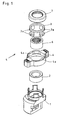
- the holding and storage device shown in the figures for substantially cylindrical instrument body having medical instruments consists, in particular from the exploded view according to Fig. 1 it can be seen, for example, from a base body 1 which can be fixed to an operating table and a guide ring 2 which can be inserted into the base body 1, an annular clamping sleeve 3 having four retaining arms 3a and a clamping nut 4 which can be placed on the clamping sleeve 3 and which together form an instrument receiver 5, as well as into the Clamping sleeve 3 of the instrument holder 5 insertable annular support member 6 and an upper cover ring. 7
- a holding device on the clamping nut 4 preferred directions of rotation for opening and closing the instrument holder 5 are given due to the structural design, the principal possibility, the clamping nut 4 to open and close the instrument holder 5 to rotate in both directions.
- the instrument holder 5 further comprises an inserted into the clamping sleeve 3 annular support member 6, which made of an elastic material is used to ensure a secure and gentle hold of the inserted instrument holder 5 instrument body.
- the holding element 6 surrounds the entire receiving space and thus also the entire instrument body.
- the instrument body in the elastically deformable, preferably made of a rubber-like material holding member 6 and to avoid the occurrence of so-called “creaking" due to the stick-slip effect, which is the male instrument body facing inner surface 6a of the elastic support member 6 in the clamping position only partially on the instrument body.
- the inner surface 6a of the holding member 6 is formed serrated for this purpose.
- stick-slip effect also called stick-slip - two materials are stimulated by relative movements to each other in an interplay between static and sliding friction. This back and forth between sliding and snagging is the cause of these "creaking noises".
- a trained as described holding and storage device for substantially cylindrical instrument body having medical instruments is characterized in that the instrument holder 5 is designed as a quick release closure. This embodiment allows the surgeon a simple and safe operation of the holding device with one hand.
Landscapes
- Health & Medical Sciences (AREA)
- Surgery (AREA)
- Life Sciences & Earth Sciences (AREA)
- Medical Informatics (AREA)
- Animal Behavior & Ethology (AREA)
- Engineering & Computer Science (AREA)
- Biomedical Technology (AREA)
- Heart & Thoracic Surgery (AREA)
- Pathology (AREA)
- Molecular Biology (AREA)
- Nuclear Medicine, Radiotherapy & Molecular Imaging (AREA)
- General Health & Medical Sciences (AREA)
- Public Health (AREA)
- Veterinary Medicine (AREA)
- Oral & Maxillofacial Surgery (AREA)
- Endoscopes (AREA)
- Surgical Instruments (AREA)
Description
Die Erfindung betrifft eine Vorrichtung zur Ablage und Bereithaltung medizinischer Instrumente für endoskopische Untersuchungen, mit einem im wesentlichen zylindrischen Instrumentenkörper, mit einem beispielsweise an einem Operationstisch festlegbaren Grundkörper und mit einer in den Grundkörper einsetzbaren Instrumentenaufnahme, in der der Instrumentenkörper klemmend festlegbar ist.The invention relates to a device for storing and maintaining medical instruments for endoscopic examinations, with a substantially cylindrical instrument body, with a fixable for example on an operating table base body and with an insertable into the body instrument receptacle in which the instrument body is clamped.
Derartige Halte- und Ablagevorrichtung sind beispielsweise an Operationstischen angeordnet, um dem Operateur während der Operation ein sicheres Ablegen und wieder Ergreifen seiner Instrumente, beispielsweise eines Laparoskops oder Endoskops, zu ermöglichen, ohne hierfür OP-Personal zu benötigen. Wichtig bei diesen Haltevorrichtungen ist, dass diese das aufzunehmende medizinische Instrument sicher und möglichst lagestabil halten, um insbesondere ein Herunterfallen des Instruments zu verhindern.Such holding and depositing device are arranged, for example, on operating tables in order to allow the surgeon during the operation of a safe depositing and re-grasping his instruments, such as a laparoscope or endoscope, without the need for surgical staff. Important in these holding devices is that they hold the male medical instrument safely and as stable as possible, in particular to prevent falling of the instrument.
Eine aus der Praxis bekannte Halte- und Ablagevorrichtung weist hierzu eine Instrumentenaufnahme auf, in der der Instrumentenkörper des zu haltenden medizinischen Instruments klemmend festlegbar ist, wobei das klemmende Halten über eine Spannschraube bewirkt wird, die nach mehreren Umdrehungen die Instrumentenaufnahme so verengt, dass der Instrumentenkörper sicher gehalten wird. Diese bekannte Halte- und Ablagevorrichtung gewährleistet zwar einen sicheren Halt des aufzunehmenden medizinischen Instruments, jedoch ist deren Bedienung für den Operateur umständlich, da das Lösen der Spannschraube einerseits Zeit kostet und andererseits in der Regel nur mit zwei Händen zu bewerkstelligen ist.A known from practice holding and depositing device has for this purpose an instrument receptacle in which the instrument body of the medical instrument to be held is clamped, wherein the clamping holding is effected via a clamping screw which narrows the instrument receptacle after several turns so that the instrument body is held securely. Although this known holding and storage device ensures a secure hold of the male medical instrument, but their operation is cumbersome for the surgeon, since the release of the clamping screw on the one hand costs time and on the other hand usually can be accomplished only with two hands.
Aus der
Weiterhin ist aus der
Dieser bekannte Klemmmechanismus besteht im Wesentlichen aus einer Aufnahme, in die der zu haltende Katheter in Längsrichtung einfügbar ist. Ein Teilbereich der Aufnahme ist als aus vier Haltearmen bestehende Spannhülse ausgebildet. Zum Festlegen des in der Aufnahme angeordneten Katheters sind die Haltearme über eine auf die Spannhülse aufsetzbare Spannschraube radial nach innen drückbar. In der Spannhülse ist ein hülsenförmiges elastisches Halteelement angeordnet, dass durch die radial nach innen gedrückten Haltearme ebenfalls radial nach innen verformt wird, bis es vollflächig an der Mantelfläche des zu haltenden Katheters anliegt.This known clamping mechanism consists essentially of a receptacle into which the catheter to be held in the longitudinal direction can be inserted. A portion of the receptacle is designed as consisting of four retaining arms clamping sleeve. To set the catheter arranged in the receptacle, the holding arms can be pressed radially inwards via a clamping screw that can be placed on the clamping sleeve. In the clamping sleeve, a sleeve-shaped elastic retaining element is arranged that is also deformed radially inwardly by the radially inwardly pressed retaining arms until it rests over the entire surface of the lateral surface of the catheter to be held.
Aus dem
Davon ausgehend liegt der Erfindung die Aufgabe zugrunde, eine Halte- und Ablagevorrichtung für medizinische Instrumente mit einem im Wesentlichen zylindrischen Instrumentenkörper zu schaffen, die bei einfachem Aufbau schnell und sicher zu betätigen ist und das Auftreten des Stick-Slip-Effekts vermeidet.Based on this, the invention has for its object to provide a holding and storage device for medical instruments with a substantially cylindrical instrument body, which is quick and safe to operate with a simple structure and avoids the occurrence of the stick-slip effect.
Die Lösung dieser Aufgabenstellung ist erfindungsgemäß dadurch gekennzeichnet, dass die Instrumentenaufnahme eine mindestens zwei Haltearme aufweisende ringförmige Spannhülse sowie eine mit der Spannhülse zusammenwirkende Spannmutter umfasst, wobei in der Spannhülse ein aus einem elastisch verformbaren Material bestehendes, ringförmiges Halteelement zur Aufnahme des Instrumentenkörpers angeordnet ist, dessen dem aufzunehmenden Instrumentenkörper zugewandte Innenfläche zur Minimierung der Kontaktfläche mit dem Instrumentenkörper gezahnt so ausgebildet ist, dass diese in der Klemmstellung nur im Bereich der Zähne am Instrumentenkörper anliegt.The solution to this problem is inventively characterized in that the instrument receptacle comprises at least two retaining arms having annular clamping sleeve and cooperating with the clamping sleeve clamping nut, wherein in the clamping sleeve consisting of an elastically deformable material, annular support member for receiving the instrument body is arranged The inner surface facing the male instrument body is minimized so as to minimize the contact surface with the instrument body so that it rests in the clamping position only in the region of the teeth on the instrument body.
Die erfindungsgemäße Ausstattung der Instrumentenaufnahme mit der Spannhülse sowie der mit der Spannhülse zusammenwirkenden Spannmutter ermöglicht einen einfachen und kostengünstigen Aufbau der Halte- und Ablagevorrichtung.The inventive equipment of the instrument holder with the clamping sleeve and cooperating with the clamping sleeve clamping nut allows a simple and inexpensive construction of the holding and storage device.
Durch das in die Spannhülse einsetzbare, aus einem elastisch verformbaren Material bestehende ringförmige Halteelement zur Aufnahme des Instrumentenkörpers wird der sichere und schonende Halt des Instrumentenkörpers in der Instrumentenaufnahme verbessert.By insertable into the clamping sleeve, consisting of an elastically deformable material annular retaining element for receiving the instrument body of safe and gentle hold of the instrument body is improved in the instrument holder.
Um einerseits das Einsetzen des Instrumentenkörpers in das elastisch verformbare Halteelement der Instrumentenaufnahme zu erleichtern und andererseits das Auftreten sogenannter "Knarzgeräusche" aufgrund des Stick-Slip-Effekts zu vermeiden, liegt die dem aufzunehmenden Instrumentenkörper zugewandte Innenfläche des elastischen Halteelements in der Klemmstellung nur bereichsweise am Instrumentenkörper an, wozu zur Minimierung der Kontaktfläche die dem aufzunehmenden Instrumentenkörper zugewandte Innenfläche des elastischen Halteelements gezahnt ausgebildet ist. Da der Stick-Slip-Effekt durch ein Wechselspiel von Haft- und Gleitreibung zweier entlang einander gleitender Materialien auftritt, stellt die Minimierung der gegenseitigen Kontaktflächen eine geeignete Maßnahme zur Vermeidung dieser "Knarzgeräusche" dar.On the one hand to facilitate the insertion of the instrument body in the elastically deformable support member of the instrument recording and on the other hand to avoid the occurrence of so-called "creaking" due to the stick-slip effect, which is the male instrument body facing inner surface of the elastic support member in the clamping position only partially on the instrument body to which, to minimize the contact surface, the inner surface of the elastic holding element facing the male instrument body is toothed. Since the stick-slip effect occurs through an interplay of static friction and sliding friction of two materials sliding along one another, minimizing the mutual contact surfaces is a suitable measure for avoiding these "creaking noises".
Gemäß einer praktischen Ausführungsform der Erfindung wird vorgeschlagen, dass die Haltearme der Spannhülse über an der Spannmutter ausgebildete Spannelemente im wesentlichen radial verformbar sind. Das klemmende Halten des Instrumentenkörpers in der Instrumentenaufnahme erfolgt dabei durch das radial nach innen Verformen der Haltearme der Spannzange, wenn die Spannelemente der Spannmutter gegen die Haltearme anlaufen. Da die Haltearme der Spannzange durch jedes Spannelement klemmend nach innen gedrückt werden, bilden diese zusammenwirkenden Spannwerkzeuge einen Schnellspannverschluss bei dem es keiner vollständigen Umdrehung der Spannmutter bedarf, um ein in die Haltevorrichtung eingestecktes medizinisches Instrument sicher festzulegen und wieder zu lösen.According to a practical embodiment of the invention, it is proposed that the retaining arms of the clamping sleeve are deformed substantially radially by means of clamping elements formed on the clamping nut. The clamping holding the instrument body in the instrument holder is carried out by the radially inwardly deforming the retaining arms of the collet, when the clamping elements of the clamping nut start against the retaining arms. Since the retaining arms of the collet are pressed by each clamping element inwardly by clamping, these cooperating clamping tools form a quick release in which it does not require a complete rotation of the clamping nut to securely set and re-inserted into the holding device medical instrument.
Vorzugsweise weist die erfindungsgemäße Spannhülse vier gleichmäßig um den Umfang der ringförmigen Spannhülse angeordnete Haltearme auf, die über vier an der Spannmutter ausgebildete, als Spannelemente dienende Nocken verformbar sind. Bei dieser Ausführungsform bedarf es lediglich einer viertel Umdrehung der Spannmutter, um die Haltevorrichtung von der Offenstellung in die Klemmstellung bzw. von der Klemmstellung in die Offenstellung zu überführen.Preferably, the clamping sleeve according to the invention has four retaining arms which are arranged uniformly around the circumference of the annular clamping sleeve and which are deformable via four cams formed on the clamping nut and serving as clamping elements. In this embodiment, it requires only a quarter turn of the clamping nut in order to transfer the holding device from the open position into the clamping position or from the clamping position into the open position.
Weitere Merkmale und Vorteile der Erfindung ergeben sich anhand der zugehörigen Zeichnung, in der ein Ausführungsbeispiel einer erfindungsgemäßen Halte- und Ablagevorrichtung für im wesentlichen zylindrische Instrumentenkörper aufweisende medizinische Instrumente beispielhaft dargestellt ist. In der Zeichnung zeigt:
- Fig. 1
- eine Explosionszeichnung einer erfindungsgemäßen Halte- und Ablagevorrichtung für medizinische Instrumente mit einem im wesentlichen zylindrischen Instrumentenkörper;
- Fig. 2
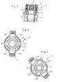
- einen Längsschnitt durch die Haltevorrichtung gemäß
Fig. 1 im zusammengebauten Zustand; - Fig. 3
- eine ausschnittweise Draufsicht auf die Haltevorrichtung gemäß
Fig. 2 , die Offenstellung darstellend und - Fig. 4
- eine Draufsicht gemäß
Fig. 3 , jedoch die Klemmstellung darstellend.
- Fig. 1
- an exploded view of a holding and storage device according to the invention for medical instruments with a substantially cylindrical instrument body;
- Fig. 2
- a longitudinal section through the holding device according to
Fig. 1 in the assembled state; - Fig. 3
- a fragmentary plan view of the holding device according to
Fig. 2 representing the open position and - Fig. 4
- a plan view according to
Fig. 3 but showing the clamping position.
Die in den Abbildungen dargestellte Halte- und Ablagevorrichtung für im wesentlichen zylindrische Instrumentenkörper aufweisende medizinische Instrumente besteht, wie insbesondere aus der Explosionszeichnung gemäß
Alternativ zum Festlegung des Grundkörpers 1 der Halte- und Ablagevorrichtung an einem Operationstisch ist es selbstverständlich auch möglich, den Grundkörper 1 an einem anderen Gegenstand, beispielsweise einem Gerätetisch oder einem separaten Ständer festzulegen.As an alternative to fixing the
Insbesondere aus den Abbildungen
Wie insbesondere aus den Draufsichten gemäß
Das klemmende Ergreifen eines in die Instrumentenaufnahme 5 eingesetzten medizinischen Instruments erfolgt dabei wie folgt:
- In der in
Fig. 3 dargestellten Offenstellung derInstrumentenaufnahme 5 sind dieNocken 4a der dieSpannhülse 3 koaxialumgebenden Spannmutter 4 jeweils abwechselnd zwischen denHaltearmen 3a derSpannhülse 3 angeordnet. Sobald dieSpannmutter 4 um eine viertel Umdrehung nach rechts oder links gedreht wird, laufen dieNocken 4a derSpannmutter 4 gegen dieHaltearme 3a derSpannhülse 3 an und drücken diese im wesentlichen radial nach innen, so dass der Aufnahmeraum im Inneren der Spannhülse im Durchmesser verkleinert wird, wie dies die in AbbildungFig. 4 dargestellte Klemmstellung zeigt.
- In the in
Fig. 3 illustrated open position of theinstrument holder 5, thecams 4a of theclamping sleeve 3 coaxially surroundingclamping nut 4 are each arranged alternately between theholding arms 3a of theclamping sleeve 3. Once thenut 4 is turned one-quarter turn to the right or left, run thecams 4a of theclamping nut 4 against theretaining arms 3a of theclamping sleeve 3 and press them substantially radially inward, so that the receiving space is reduced in diameter inside the clamping sleeve, as shown in FigureFig. 4 shown clamping position shows.
Ein in diesem Aufnahmeraum angeordneter Instrumentenkörper wird in der Klemmstellung von den radial nach innen verformten Haltearmen 3a der Spannhülse 3 klemmend ergriffen und in seiner Lage fixiert.Arranged in this receiving space instrument body is gripped in the clamping position of the radially inwardly deformed holding
Zum Öffnen der Instrumentenaufnahme 5 ist es lediglich notwendig, die Spannmutter 4 wieder um eine viertel Umdrehung nach rechts oder links zu drehen, bis die Nocken 4a der Spannmutter 4 nicht mehr in Eingriff mit den Haltearmen 3a der Spannhülse 3 stehen.To open the
Auch wenn bei der dargestellten Ausführungsform einer Haltevorrichtung auf der Spannmutter 4 bevorzugte Drehrichtungen zum Öffnen und Schließen der Instrumentenaufnahme 5 angegeben sind, besteht aufgrund der konstruktiven Ausgestaltung die prinzipielle Möglichkeit, die Spannmutter 4 zum Öffnen und Schließen der Instrumentenaufnahme 5 jeweils in beide Richtungen zu drehen.Although in the illustrated embodiment, a holding device on the clamping
Ebenso ist es selbstverständlich möglich, die Spannhülse 3 mit mehr oder weniger vielen Haltearmen 3a auszustatten. Um ein einfaches und schnelles Betätigen der Instrumentenaufnahme 5 zu gewährleisten, ist es vorteilhaft, wenn die Anzahl der Nocken 4a der Spannmutter 4 der Anzahl der Haltearme 3a der Spannhülse 3 entspricht.Likewise, it is of course possible to equip the
Wie weiterhin aus den Abbildungen ersichtlich, weist die Instrumentenaufnahme 5 weiterhin ein in die Spannhülse 3 eingesetztes ringförmiges Halteelement 6 auf, das aus einem elastischen Material hergestellt dazu dient, einen sicheren und schonenden Halt des in die Instrumentenaufnahme 5 eingesetzten Instrumentenkörpers zu gewährleisten. Im Gegensatz zu den radial nach innen gebogenen, nur punktuell angreifenden Haltearmen 3a umschließt das Halteelement 6 den gesamten Aufnahmeraum und somit auch den gesamten Instrumentenkörper.As further shown in the figures, the
Um das Einsetzen des Instrumentenkörpers in das elastisch verformbare, vorzugsweise aus einem gummiartigen Material gefertigte Halteelement 6 zu erleichtern und das Auftreten sogenannter "Knarzgeräusche" aufgrund des Stick-Slip-Effekts zu vermeiden, liegt die dem aufzunehmenden Instrumentenkörper zugewandte Innenfläche 6a des elastischen Halteelements 6 in der Klemmstellung nur bereichsweise am Instrumentenkörper an. Bei der dargestellten Ausführungsform ist die Innenfläche 6a des Halteelements 6 zu diesem Zweck gezahnt ausgebildet.In order to facilitate the insertion of the instrument body in the elastically deformable, preferably made of a rubber-like
Bei dem Stick-Slip-Effekt - auch Ruckgleiten genannt - geraten zwei Materialien angeregt durch Relativbewegungen zueinander in ein Wechselspiel zwischen Haft-und Gleitreibung. Dieses Hin und Her zwischen Gleiten und Verhaken ist die Ursache für diese "Knarzgeräusche". Durch die Minimierung der Kontaktflächen zwischen dem Halteelement 6 einerseits und dem Instrumentenkörper andererseits wird das Auftreten des Stick-Slip-Effekts beim Einstecken und Herausziehen des Instrumentenkörpers aus der Instrumentenaufnahme 5 vermieden.In the stick-slip effect - also called stick-slip - two materials are stimulated by relative movements to each other in an interplay between static and sliding friction. This back and forth between sliding and snagging is the cause of these "creaking noises". By minimizing the contact surfaces between the retaining
Eine wie beschrieben ausgebildete Halte- und Ablagevorrichtung für im wesentlichen zylindrische Instrumentenkörper aufweisende medizinische Instrumente zeichnet sich dadurch aus, dass die Instrumentenaufnahme 5 als Schnellspannverschluss ausgebildet ist. Diese Ausgestaltung ermöglicht dem Operateur ein einfaches und sicheres Bedienen der Haltevorrichtung auch mit nur einer Hand.A trained as described holding and storage device for substantially cylindrical instrument body having medical instruments is characterized in that the
- 11
- Grundkörperbody
- 22
- Führungsringguide ring
- 33
- Spannhülseclamping sleeve
- 3a3a
- Haltearmholding arm
- 44
- Spannmutterlocknut
- 4a4a
- Nockencam
- 55
- Instrumentenaufnahmeinstrument holder
- 66
- Halteelementretaining element
- 6a6a
- Innenflächepalm
- 77
- Abdeckringcover ring
Claims (3)
- Device for storing and presenting medical instruments for endoscopic examinations, with a substantially cylindrical instrument body, with a base body (1) which can be immobilized on an operating table, for example, and with an instrument receiver (5) which can be inserted in the base body (1), and in which the instrument body can be immobilized by clamping,
characterized in
that the instrument receiver (5) includes an annular clamping sleeve (3) comprising at least two supporting arms (3a), as well as a clamping nut (4) which works together with the clamping sleeve (3), wherein, in the clamping sleeve (3), an annular supporting element (6) consisting of a resiliently deformable material is arranged for receiving the instrument body, the inner surface (6a) of said supporting element, which faces the instrument body to be received, being formed with toothing to minimize the contact surface with the instrument body. in such a manner that said contact surface in the clamping position rests only in the area of the teeth against the instrument body. - Device according to Claim 1, characterized in that the supporting arms (3a) of the clamping sleeve (3) are substantially radially deformable by means of clamping elements formed on the clamping nut (4).
- Device according to Claim 2, characterized in that the clamping sleeve (3) comprises four supporting arms (3a) which are arranged regularly around the circumference of the annular clamping sleeve (3), and which are deformable by means of four cams (4a) formed on the clamping nut (4) and used as clamping elements.
Applications Claiming Priority (1)
| Application Number | Priority Date | Filing Date | Title |
|---|---|---|---|
| DE102004043982A DE102004043982B4 (en) | 2004-09-11 | 2004-09-11 | Holding device for cylindrical instrument body medical instruments |
Publications (2)
| Publication Number | Publication Date |
|---|---|
| EP1634544A1 EP1634544A1 (en) | 2006-03-15 |
| EP1634544B1 true EP1634544B1 (en) | 2014-10-08 |
Family
ID=35427734
Family Applications (1)
| Application Number | Title | Priority Date | Filing Date |
|---|---|---|---|
| EP05018034.8A Expired - Fee Related EP1634544B1 (en) | 2004-09-11 | 2005-08-19 | Holding device for medical instruments with substantially cylindrical body |
Country Status (3)
| Country | Link |
|---|---|
| US (1) | US8066630B2 (en) |
| EP (1) | EP1634544B1 (en) |
| DE (1) | DE102004043982B4 (en) |
Families Citing this family (13)
| Publication number | Priority date | Publication date | Assignee | Title |
|---|---|---|---|---|
| DE102006010316A1 (en) * | 2006-03-07 | 2007-09-13 | Karl Storz Gmbh & Co. Kg | clutch mechanism |
| US7766922B1 (en) * | 2006-04-21 | 2010-08-03 | Advanced Neuromodulation Systems, Inc. | Burr hole caps and methods of use |
| US20080047064A1 (en) * | 2006-08-02 | 2008-02-28 | Theran Michael E | Surgical equipment supporting frames and attachments for same |
| DE102006055172A1 (en) | 2006-11-23 | 2008-05-29 | Karl Storz Gmbh & Co. Kg | Device for clamping fixing on cylindrical components of medical instruments |
| US8333689B2 (en) * | 2008-05-13 | 2012-12-18 | Olympus Medical Systems Corp. | Medical operation device |
| EP2903549B1 (en) * | 2012-08-06 | 2017-02-15 | Prometheus Medical Innovations LLC | Head stabilizer for medical device(s) including an endotracheal tube |
| US9386963B2 (en) * | 2012-09-25 | 2016-07-12 | Boston Scientific Scimed, Inc. | Biopsy channel attachment adaptor |
| DE102012112712A1 (en) * | 2012-12-20 | 2014-06-26 | MAQUET GmbH | instrument support |
| DE102012112716A1 (en) | 2012-12-20 | 2014-06-26 | MAQUET GmbH | Medical support arm |
| JP6266756B2 (en) * | 2014-03-27 | 2018-01-24 | 富士フイルム株式会社 | Surgical device for outer tube and endoscope |
| DE102016117751B4 (en) | 2016-09-21 | 2018-05-30 | Medineering Gmbh | Medical support arm with mechatronic interface and system consisting of the support arm and an assistance system |
| EP3790619A4 (en) * | 2018-05-08 | 2022-02-16 | Baylis Medical Company Inc. | Coupling mechanisms for medical devices |
| TWI740673B (en) * | 2020-10-08 | 2021-09-21 | 國立中央大學 | Surgical instrument holder |
Citations (4)
| Publication number | Priority date | Publication date | Assignee | Title |
|---|---|---|---|---|
| US5441042A (en) * | 1991-08-05 | 1995-08-15 | Putman; John M. | Endoscope instrument holder |
| US5944696A (en) * | 1996-06-03 | 1999-08-31 | Bayless; William Brian | Swivel clip medical tube holder |
| NL1015663C2 (en) * | 2000-07-10 | 2002-01-15 | Gerardus Willem Akkerhuis | Fixing device for securing e.g. cannula or catheter to human body comprising orientation devices on foot plate for fixing cannula or catheter clamping part into position |
| US6428514B1 (en) * | 1997-11-14 | 2002-08-06 | B. Braun Melsungen Ag | Device for administering liquids to a patient |
Family Cites Families (17)
| Publication number | Priority date | Publication date | Assignee | Title |
|---|---|---|---|---|
| US4289891A (en) * | 1978-04-21 | 1981-09-15 | General Electric Company | Silicone diffusion pump fluids |
| US4287891A (en) * | 1979-08-31 | 1981-09-08 | Peters Joseph L | Securing device for surgical tubes |
| CA2001732A1 (en) * | 1988-10-31 | 1990-04-30 | Lawrence A. Lynn | Intravenous line coupling device |
| US4900182A (en) * | 1989-03-22 | 1990-02-13 | Stillwagon Applied Techonology Incorporated | Lock and release apparatus |
| US5236939A (en) | 1989-09-23 | 1993-08-17 | Bayer Aktiengesellschaft | Substituted 1,3,4-oxa(thia)diazolinones process for their preparation and their use of combating endoparasites |
| US5127626A (en) * | 1989-10-31 | 1992-07-07 | Applied Vascular Devices, Inc. | Apparatus for sealing around members extending therethrough |
| US5279597A (en) | 1992-01-13 | 1994-01-18 | Arrow International Investment Corp. | Catheter compression clamp |
| US5275614A (en) * | 1992-02-21 | 1994-01-04 | Habley Medical Technology Corporation | Axially extendable endoscopic surgical instrument |
| US5263939A (en) * | 1992-10-09 | 1993-11-23 | Surgin Surgical Instrumentation, Inc. | Retainer for laparoscopic cannula |
| US5380302A (en) * | 1993-02-10 | 1995-01-10 | Unisurge, Inc. | Cannula fixation device with retaining ring having identations |
| US5437645A (en) * | 1993-10-08 | 1995-08-01 | United States Surgical Corporation | Surgical instrument positioning device |
| US5366446A (en) * | 1993-11-17 | 1994-11-22 | Unisurge, Inc. | Introducer assembly |
| US5555881A (en) * | 1994-07-11 | 1996-09-17 | Aeroquip Corporation | Endotracheal tube positioner |
| DE19625729C2 (en) * | 1996-06-27 | 1999-09-02 | Wolf Gmbh Richard | Support arm system |
| US6190372B1 (en) * | 1998-08-14 | 2001-02-20 | Epimed International, Inc. | Catheter connector |
| US6228059B1 (en) * | 1999-06-16 | 2001-05-08 | Denis C. Astarita | Endoscopic instrument locks |
| DE20214608U1 (en) * | 2002-09-16 | 2002-12-19 | Berlin Heart Ag | Device for connecting a pipe end made of flexible material with a spout |
-
2004
- 2004-09-11 DE DE102004043982A patent/DE102004043982B4/en not_active Expired - Fee Related
-
2005
- 2005-08-19 EP EP05018034.8A patent/EP1634544B1/en not_active Expired - Fee Related
- 2005-09-12 US US11/224,453 patent/US8066630B2/en active Active
Patent Citations (4)
| Publication number | Priority date | Publication date | Assignee | Title |
|---|---|---|---|---|
| US5441042A (en) * | 1991-08-05 | 1995-08-15 | Putman; John M. | Endoscope instrument holder |
| US5944696A (en) * | 1996-06-03 | 1999-08-31 | Bayless; William Brian | Swivel clip medical tube holder |
| US6428514B1 (en) * | 1997-11-14 | 2002-08-06 | B. Braun Melsungen Ag | Device for administering liquids to a patient |
| NL1015663C2 (en) * | 2000-07-10 | 2002-01-15 | Gerardus Willem Akkerhuis | Fixing device for securing e.g. cannula or catheter to human body comprising orientation devices on foot plate for fixing cannula or catheter clamping part into position |
Also Published As
| Publication number | Publication date |
|---|---|
| DE102004043982A1 (en) | 2006-03-30 |
| DE102004043982B4 (en) | 2010-04-01 |
| US8066630B2 (en) | 2011-11-29 |
| US20060058579A1 (en) | 2006-03-16 |
| EP1634544A1 (en) | 2006-03-15 |
Similar Documents
| Publication | Publication Date | Title |
|---|---|---|
| EP1634544B1 (en) | Holding device for medical instruments with substantially cylindrical body | |
| EP1219266B1 (en) | Implant for the insertion between the vertebraes and operation tool for using the implant | |
| DE4401237C2 (en) | Trocar device | |
| EP2563283B1 (en) | Vertebral column implant and tool for said implant | |
| EP3586783B1 (en) | Trocar holder | |
| DE102011018692B4 (en) | Spinal implant, tool and method of distraction of the spinal implant | |
| EP2279709A1 (en) | Container for a medical instrument or implant, in particular a dental instrument or a dental implant | |
| DE1791102B1 (en) | Clamping device for surgical purposes | |
| DE1575701B2 (en) | MANIPULATOR FOR CURVING AND STRETCHING THE FREE END OF A WIRE COIL FOR MEDICAL PURPOSES | |
| DE2513241B2 (en) | Device for inserting an intrauterine insert | |
| EP1083834B1 (en) | Device for producing a transcutaneous access to a hollow viscus in the interior of the body | |
| EP1959184B1 (en) | Holder for medicinal purposes | |
| EP1711215B1 (en) | Device and method for introducing a plug into the peritoneal dialysis connector of a patient | |
| EP1925260B1 (en) | Device for affixing medical instruments to cylindrical components | |
| EP1414512A2 (en) | Assembly part for an adapter of a peg tube and adapter for a peg tube comprising an assembly part of this type | |
| DE19700474A1 (en) | Surgical instrument | |
| DE102008031387A1 (en) | Medical clip | |
| EP0603423B1 (en) | Device for the implantation of an endoprothesis | |
| DE112018001342T5 (en) | A controlled torque holding and tightening medical instrument of a threaded implant device and packaging thereof | |
| DE4318019A1 (en) | Bendable handpiece for instruments for endoscopic surgery | |
| AT514923B1 (en) | Surgical suturing instrument for minimally invasive surgery and needle holder coupling for such an instrument | |
| DE102022116383A1 (en) | SURGICAL INSTRUMENT, METHOD FOR ASSEMBLY THEREOF AND METHOD FOR DISASSEMBLY THEREOF | |
| EP3695809A1 (en) | Ophthalmological hand-held device | |
| DE1575701C3 (en) | Manipulator for bending and stretching the free end of a wire helix for medical purposes | |
| EP2719354A2 (en) | Instrument mount |
Legal Events
| Date | Code | Title | Description |
|---|---|---|---|
| PUAI | Public reference made under article 153(3) epc to a published international application that has entered the european phase |
Free format text: ORIGINAL CODE: 0009012 |
|
| AK | Designated contracting states |
Kind code of ref document: A1 Designated state(s): AT BE BG CH CY CZ DE DK EE ES FI FR GB GR HU IE IS IT LI LT LU LV MC NL PL PT RO SE SI SK TR |
|
| AX | Request for extension of the european patent |
Extension state: AL BA HR MK YU |
|
| 17P | Request for examination filed |
Effective date: 20060830 |
|
| 17Q | First examination report despatched |
Effective date: 20061016 |
|
| AKX | Designation fees paid |
Designated state(s): DE FR GB IT |
|
| APBK | Appeal reference recorded |
Free format text: ORIGINAL CODE: EPIDOSNREFNE |
|
| APBN | Date of receipt of notice of appeal recorded |
Free format text: ORIGINAL CODE: EPIDOSNNOA2E |
|
| APBR | Date of receipt of statement of grounds of appeal recorded |
Free format text: ORIGINAL CODE: EPIDOSNNOA3E |
|
| APAF | Appeal reference modified |
Free format text: ORIGINAL CODE: EPIDOSCREFNE |
|
| APBT | Appeal procedure closed |
Free format text: ORIGINAL CODE: EPIDOSNNOA9E |
|
| GRAP | Despatch of communication of intention to grant a patent |
Free format text: ORIGINAL CODE: EPIDOSNIGR1 |
|
| INTG | Intention to grant announced |
Effective date: 20140528 |
|
| GRAS | Grant fee paid |
Free format text: ORIGINAL CODE: EPIDOSNIGR3 |
|
| GRAA | (expected) grant |
Free format text: ORIGINAL CODE: 0009210 |
|
| AK | Designated contracting states |
Kind code of ref document: B1 Designated state(s): DE FR GB IT |
|
| REG | Reference to a national code |
Ref country code: GB Ref legal event code: FG4D Free format text: NOT ENGLISH |
|
| REG | Reference to a national code |
Ref country code: DE Ref legal event code: R081 Ref document number: 502005014538 Country of ref document: DE Owner name: KARL STORZ SE & CO. KG, DE Free format text: FORMER OWNER: KARL STORZ GMBH & CO. KG, 78532 TUTTLINGEN, DE |
|
| REG | Reference to a national code |
Ref country code: DE Ref legal event code: R096 Ref document number: 502005014538 Country of ref document: DE Effective date: 20141120 |
|
| REG | Reference to a national code |
Ref country code: DE Ref legal event code: R097 Ref document number: 502005014538 Country of ref document: DE |
|
| PLBE | No opposition filed within time limit |
Free format text: ORIGINAL CODE: 0009261 |
|
| STAA | Information on the status of an ep patent application or granted ep patent |
Free format text: STATUS: NO OPPOSITION FILED WITHIN TIME LIMIT |
|
| 26N | No opposition filed |
Effective date: 20150709 |
|
| REG | Reference to a national code |
Ref country code: FR Ref legal event code: PLFP Year of fee payment: 12 |
|
| PGFP | Annual fee paid to national office [announced via postgrant information from national office to epo] |
Ref country code: IT Payment date: 20160722 Year of fee payment: 12 |
|
| REG | Reference to a national code |
Ref country code: FR Ref legal event code: PLFP Year of fee payment: 13 |
|
| REG | Reference to a national code |
Ref country code: DE Ref legal event code: R081 Ref document number: 502005014538 Country of ref document: DE Owner name: KARL STORZ SE & CO. KG INTELLECTUAL PROPERTY, DE Free format text: FORMER OWNER: KARL STORZ GMBH & CO. KG, 78532 TUTTLINGEN, DE Ref country code: DE Ref legal event code: R082 Ref document number: 502005014538 Country of ref document: DE Representative=s name: HOFMEISTER, FRANK, DIPL.-ING., DE Ref country code: DE Ref legal event code: R081 Ref document number: 502005014538 Country of ref document: DE Owner name: KARL STORZ SE & CO. KG, DE Free format text: FORMER OWNER: KARL STORZ GMBH & CO. KG, 78532 TUTTLINGEN, DE |
|
| REG | Reference to a national code |
Ref country code: FR Ref legal event code: PLFP Year of fee payment: 14 |
|
| PG25 | Lapsed in a contracting state [announced via postgrant information from national office to epo] |
Ref country code: IT Free format text: LAPSE BECAUSE OF NON-PAYMENT OF DUE FEES Effective date: 20170819 |
|
| PGFP | Annual fee paid to national office [announced via postgrant information from national office to epo] |
Ref country code: FR Payment date: 20190722 Year of fee payment: 15 |
|
| PGFP | Annual fee paid to national office [announced via postgrant information from national office to epo] |
Ref country code: GB Payment date: 20190722 Year of fee payment: 15 |
|
| PGFP | Annual fee paid to national office [announced via postgrant information from national office to epo] |
Ref country code: DE Payment date: 20200721 Year of fee payment: 16 |
|
| GBPC | Gb: european patent ceased through non-payment of renewal fee |
Effective date: 20200819 |
|
| PG25 | Lapsed in a contracting state [announced via postgrant information from national office to epo] |
Ref country code: FR Free format text: LAPSE BECAUSE OF NON-PAYMENT OF DUE FEES Effective date: 20200831 |
|
| PG25 | Lapsed in a contracting state [announced via postgrant information from national office to epo] |
Ref country code: GB Free format text: LAPSE BECAUSE OF NON-PAYMENT OF DUE FEES Effective date: 20200819 |
|
| REG | Reference to a national code |
Ref country code: DE Ref legal event code: R119 Ref document number: 502005014538 Country of ref document: DE |
|
| PG25 | Lapsed in a contracting state [announced via postgrant information from national office to epo] |
Ref country code: DE Free format text: LAPSE BECAUSE OF NON-PAYMENT OF DUE FEES Effective date: 20220301 |