EP1511600B1 - A control system for controlling the movements of at least two robots - Google Patents
A control system for controlling the movements of at least two robots Download PDFInfo
- Publication number
- EP1511600B1 EP1511600B1 EP03738815A EP03738815A EP1511600B1 EP 1511600 B1 EP1511600 B1 EP 1511600B1 EP 03738815 A EP03738815 A EP 03738815A EP 03738815 A EP03738815 A EP 03738815A EP 1511600 B1 EP1511600 B1 EP 1511600B1
- Authority
- EP
- European Patent Office
- Prior art keywords
- modules
- module
- control system
- control
- drive
- Prior art date
- Legal status (The legal status is an assumption and is not a legal conclusion. Google has not performed a legal analysis and makes no representation as to the accuracy of the status listed.)
- Expired - Lifetime
Links
Images
Classifications
-
- B—PERFORMING OPERATIONS; TRANSPORTING
- B25—HAND TOOLS; PORTABLE POWER-DRIVEN TOOLS; MANIPULATORS
- B25J—MANIPULATORS; CHAMBERS PROVIDED WITH MANIPULATION DEVICES
- B25J9/00—Programme-controlled manipulators
- B25J9/16—Programme controls
- B25J9/1602—Programme controls characterised by the control system, structure, architecture
- B25J9/161—Hardware, e.g. neural networks, fuzzy logic, interfaces, processor
-
- G—PHYSICS
- G05—CONTROLLING; REGULATING
- G05B—CONTROL OR REGULATING SYSTEMS IN GENERAL; FUNCTIONAL ELEMENTS OF SUCH SYSTEMS; MONITORING OR TESTING ARRANGEMENTS FOR SUCH SYSTEMS OR ELEMENTS
- G05B2219/00—Program-control systems
- G05B2219/30—Nc systems
- G05B2219/34—Director, elements to supervisory
- G05B2219/34204—Independent units, stackthrough in cabinet, no backplane
-
- G—PHYSICS
- G05—CONTROLLING; REGULATING
- G05B—CONTROL OR REGULATING SYSTEMS IN GENERAL; FUNCTIONAL ELEMENTS OF SUCH SYSTEMS; MONITORING OR TESTING ARRANGEMENTS FOR SUCH SYSTEMS OR ELEMENTS
- G05B2219/00—Program-control systems
- G05B2219/30—Nc systems
- G05B2219/40—Robotics, robotics mapping to robotics vision
- G05B2219/40306—Two or more independent robots
Definitions
- the present invention relates to a control system according to the preamble of claim 1 for controlling the movements of at least two robots.
- An industrial robot comprises a plurality of arms that are rotatable relative to each other about a plurality of axes.
- the movements of the axes are driven by motors mounted on each axis.
- the speeds and accelerations of the axes are controlled by the control system of the robot that generates control signals to the motors.
- the control system comprises drives that control the motors by converting direct current to a variable alternating current in dependence on control signals from an axis computer.
- Each motor has a drive of its own.
- the control system may have one or more axis computers.
- the control system comprises a main computer that is adapted to execute a program with instructions for the movements and that supplies the axis computer with control instructions. These control instructions are then transformed by the axis computer into control signals for the drives.
- the function of the axis computer is thus to ensure that orders from the main computer are carried out.
- the task of the main computer is to plan the movement path of the robot, so-called path planning, and the task of the axis computer is to ensure that the robot completes the planned path.
- the control signals to the drives determine motor torque, motor speeds and drive currents for each axis.
- the main computer also has many other tasks, such as handling I/O systems, application programs, interpolation, and communication with external systems.
- a conventional control system for an industrial robot comprises a coherent unit, where the different parts in the control system, such as main computer, axis computer and drives, are mounted in one and the same cabinet with a common power supply, a common interface externally, and a common casing.
- the control system is provided with an internal bus for communication between the different parts.
- Such a common control system comprises a main computer or one or more axis computers as well as one drive unit per robot.
- a drive unit comprises a plurality of drives, usually between six and nine drives depending on how many motors are to be controlled.
- the axis computers and the main computer communicate via an internal bus.
- control systems are inflexible. If it is desired, for example, to add a new function or replace some part of the control system, it is necessary today to intervene and make changes in the existing control system. To be able to add more robots, the existing control system must either be oversized even from the start regarding computer utility and power supply, or the whole of or parts of the control system must be replaced or be rebuilt to obtain the necessary computer utility and power supply.
- US5,274,781 discloses a programmable controller having a plurality of modules for performing different functions which operate a machine in response to the execution of a control program.
- This document shows two physically separated units having its own power supply and surrounded by a casing of its own.
- One of the units comprises a processor module and a plurality of I/O modules and the other unit comprises a plurality of I/O modules.
- the object of the present invention is to provide a flexible control system for controlling the movement of at least two robots.
- the fact that the control system is flexible means that it is easy to connect a new robot to the control system, to add a new function to the control system, and to replace some part of the control system.
- Each module is autonomous and has its own well-defined interface with respect to the other modules.
- the separate modules may either be placed together or be geographically separated at suitable locations.
- control system Because the functions of the control system have been divided into a plurality of separate modules with their own power supply, it is easy to add a new function or to extend the capacity of the control system by connecting a new module. When something breaks down in the control system, the faulty module can simply be replaced. For each module that is added, the total power supply of the control system increases. If a new robot is to be connected to the control system, it is sufficient to connect another module to upgrade the control system. Thus, the control system need not be oversized from the start.
- independent functional units are identified and separate modules with these functions are created.
- the need of information exchange between the modules is reduced, which implies that no high bandwidth is needed for the communication channels between the modules.
- control system comprises a separate main computer module and at least two separate drive modules, the main computer being arranged in the main computer module and an axis computer being arranged in each drive module.
- each drive module is adapted to control one robot.
- a new drive module is readily connected each time a new unit is added.
- each drive module comprises a drive unit comprising a plurality of drives.
- the power supply to the drive module is adapted to the number of drives. When the control system is extended by another drive module, the power supply is automatically adapted to the number of drives and hence to the number of connected robots.
- One advantage of mounting all the drives together in the same module is that this makes it possible to provide the drives with a common cooling system.
- the control system comprises a separate transformer module, which has a transformer and is adapted to transform the incoming ac voltage to the correct voltage level for the modules.
- Different countries deliver alternating current with different voltage levels. Whether a transformer is needed, and in that case which one, depends on the country in which the system is to operate. Because the transformer is arranged as a separate module, the module is easily replaced if another transformer is needed.
- control system comprises a separate control-panel module with the control panel of the control system.
- control panel By arranging the control panel in a separate module, it is possible to integrate the control panel into some other piece of equipment so as to make it easily accessible to the operator.
- each one of the modules is enclosed in its own casing.
- the casing protects the modules against the environment and makes it possible to place the modules separately.
- the modules are advantageously arranged physically separated. In this way, the modules may be easily spread out and placed in different places. In many cases, it is advantageous to be able to spread out the modules in different places.
- the drive modules are preferably located as close to the motors as possible to obtain short cables which are less sensitive to EMC disturbances. In many branches of industry, there is a shortage of floor space due to compressed manufacturing cells and lines. With a drive system according to the invention, it is possible to place the various modules where there is free floor space.
- the modules are arranged to communicate via the Ethernet.
- Ethernet is a simple standard protocol. By arranging the modules so that they can use the Ethernet, inexpensive standard components may be used.
- control system comprises at least three such modules.
- a control system may comprise many modules, of which some modules handle different functions and others handle the same function. It is thus possible that the control system may comprise several modules with the same function.
- the control system comprises at least three modules is meant that the control system comprises three modules irrespective of whether these handle different functions or the same function.
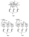
- Figure 1 shows a control system 1 according to the prior art, controlling three industrial robots 2.
- the control system 1 comprises a main computer 4, three axis computers 6 and three drive units 8, each of which including a number of drives.
- Each drive unit 8 is connected to a robot 2 and supplies the robot with control signals and electric power.
- the main computer, the axis computers and the drive units are arranged together and constitute one unit that is enclosed by a common casing 10.
- the control system has a common power-supply unit that produces voltages with the correct quality and with the correct level for all parts included in the control system.
- the main computer and the axis computers communicate with each other and with the drive units via an internal bus (not shown in the figure).
- a control system comprises at least three separate modules, which are arranged to handle different functions.
- a plurality of different types of modules are available and each type of module has its own function.
- Each module has its own well-defined interface with respect to the other modules.
- the control system composed of the separate modules need not include all types of modules and may include several modules of the same type.
- the modules have their own power supply and are arranged so as to be able to communicate with at least one of the other modules.
- a plurality of the different types of modules are also provided with their own computer utility.
- FIG. 2 shows a control system according to one embodiment of the invention, controlling three robots 2.
- the figure shows four modules, one main-computer module 12 and three drive modules 14.
- the control system also comprises other modules that are not shown in the figure.
- the main-computer module 12 comprises the main computer 4 of the control system and handles the functions of the main computer, such as executing robot programs and giving orders to the drive module regarding the movement of the robot, such as the desired position and speed.
- Each one of the drive modules 14 comprises an axis computer 6 and a drive unit 8.
- the function of the drive module is to carry out the orders of the main computer so that the robot carries out the movement ordered.
- Each module 12, 14 is enclosed in its own casing 15 and constitutes a separate physical unit.
- Each one of the drive modules 14 is directly connected to the main-computer module and communicates therewith via an Ethernet link.
- FIG. 3 shows another embodiment of a control system according to the invention, wherein the drive modules 14 instead are arranged in series.
- the first drive module is connected to the main-computer module 12 and to the second drive module, which in turn is connected to the third drive module. These connections comprise communication via the Ethernet. Electric power is transmitted separately to each module.
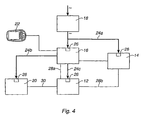
- FIG. 4 shows in more detail an embodiment of a control system according to the invention.
- the control system comprises five different types of modules: one main-computer module 12, one drive module 14, one control module 16, one transformer module 18, and one client I/O module 20.
- the main-computer module 12 includes the main computer, the communication card (RCC) of the robot, and one or more field bus cards.
- the main computer constitutes the centre of the system and it controls and reacts to communication from other parts of the system.
- the main computer executes robot programs and gives orders to the drive module regarding the position and speed of the robot.
- the drive module 14 comprises a drive unit with up to nine drives, an axis computer and a contactor card. A drive module may thus drive a six-axis robot with three external axes.
- the control module 16 comprises an operating panel with built-in power supply and the control panel of the control system with an emergency-stop button and buttons for selecting various settings as well as a main switch.
- the control module 16 constitutes the centre of the safety functions of the robot and it supervises the whole safety chain. Most of the external safety signals for the robot are connected to the operating panel.
- the control module preferably includes a computer.
- a portable programming unit (TPU) 22 is also connected to the control module 16.
- the programming unit 22 is used by an operator for programming the robot.
- the client I/O module comprises I/O panels and is adapted to receive electric equipment or other electronics. What type of electronics or equipment to install into the module is determined by the robot user. The equipment installed may, for example, be a welding machine or a painting machine. It is possible for the user to make external changes in this module so as to suit the requirements of the user.
- the transformer module 18 comprises a transformer and a switch.
- the transformer module is supplied with ac voltage from the electricity network and transforms the ac voltage into the desired voltage level.
- the transformer module in turn supplies the other modules with ac voltage. All the modules have their own power supply, which means that they are provided with a power-supply unit 26 that converts incoming alternating current into direct current and produces the voltages that are needed in the module.
- the power-supply units 26 produce voltages of the correct quality and of the correct level for its module.
- Each one of the modules 12-20 is enclosed in a casing for protection against pollutants in the surroundings.
- the modules that are in need thereof are provided with their own cooling system.
- a voltage arriving at the transformer module 18 is transformed by the transformer into a suitable voltage level and is then supplied to the modules via the cables 24a-c connected to the power-supply unit 26 in the modules.
- the main-computer module 12 communicates with the control module 16 via an Ethernet cable 28a.
- the main-computer module 12 also communicates with the drive module 14 via an Ethernet cable 28b.
- the main computer supplies the axis computer in the drive module with new references every fourth ms.
- the main-computer module 12 and the client I/O module 20 are connected to each other via a field bus 30.
- the control system may have no or several transformer modules and no or several client I/O modules, respectively. In a small robot configuration, the transformer may instead be located in the drive module.
- the invention is not limited to the embodiments shown but may be varied and modified within the scope of the appended claims.
- the division of the modules with respect to what functions they are to handle may be done in other ways than those shown in the above-described embodiments.
- the number of different types of modules may also vary.
- the principle for the division of the functions of the control system into different modules is that these functions are divided in such a way as to require as small an exchange of information between the modules as possible.
Landscapes
- Engineering & Computer Science (AREA)
- Automation & Control Theory (AREA)
- Mathematical Physics (AREA)
- Artificial Intelligence (AREA)
- Evolutionary Computation (AREA)
- Fuzzy Systems (AREA)
- Physics & Mathematics (AREA)
- Software Systems (AREA)
- Robotics (AREA)
- Mechanical Engineering (AREA)
- Numerical Control (AREA)
- Manipulator (AREA)
- Control Of Multiple Motors (AREA)
- Selective Calling Equipment (AREA)
Abstract
Description
- The present invention relates to a control system according to the preamble of claim 1 for controlling the movements of at least two robots.
- Such a control system is known from
US-A-5 241 250 . - An industrial robot comprises a plurality of arms that are rotatable relative to each other about a plurality of axes. The movements of the axes are driven by motors mounted on each axis. The speeds and accelerations of the axes are controlled by the control system of the robot that generates control signals to the motors. The control system comprises drives that control the motors by converting direct current to a variable alternating current in dependence on control signals from an axis computer. Each motor has a drive of its own. The control system may have one or more axis computers. Further, the control system comprises a main computer that is adapted to execute a program with instructions for the movements and that supplies the axis computer with control instructions. These control instructions are then transformed by the axis computer into control signals for the drives. The function of the axis computer is thus to ensure that orders from the main computer are carried out. The task of the main computer is to plan the movement path of the robot, so-called path planning, and the task of the axis computer is to ensure that the robot completes the planned path. The control signals to the drives determine motor torque, motor speeds and drive currents for each axis. The main computer also has many other tasks, such as handling I/O systems, application programs, interpolation, and communication with external systems.
- A conventional control system for an industrial robot comprises a coherent unit, where the different parts in the control system, such as main computer, axis computer and drives, are mounted in one and the same cabinet with a common power supply, a common interface externally, and a common casing. The control system is provided with an internal bus for communication between the different parts.
- From
European patent No. 728 559 B1 - It is common practice to have several robots arranged together in manufacturing cells or along a production line. In such applications, the robots are either provided with individual control systems or with a common control system. Such a common control system comprises a main computer or one or more axis computers as well as one drive unit per robot. A drive unit comprises a plurality of drives, usually between six and nine drives depending on how many motors are to be controlled. The axis computers and the main computer communicate via an internal bus.
- One disadvantage of these control systems is that they are inflexible. If it is desired, for example, to add a new function or replace some part of the control system, it is necessary today to intervene and make changes in the existing control system. To be able to add more robots, the existing control system must either be oversized even from the start regarding computer utility and power supply, or the whole of or parts of the control system must be replaced or be rebuilt to obtain the necessary computer utility and power supply.
-
US5,274,781 discloses a programmable controller having a plurality of modules for performing different functions which operate a machine in response to the execution of a control program. This document shows two physically separated units having its own power supply and surrounded by a casing of its own. One of the units comprises a processor module and a plurality of I/O modules and the other unit comprises a plurality of I/O modules. - The object of the present invention is to provide a flexible control system for controlling the movement of at least two robots. The fact that the control system is flexible means that it is easy to connect a new robot to the control system, to add a new function to the control system, and to replace some part of the control system.
- This object is achieved by a control system as defined is claim 1. Each module is autonomous and has its own well-defined interface with respect to the other modules. The separate modules may either be placed together or be geographically separated at suitable locations.
- Because the functions of the control system have been divided into a plurality of separate modules with their own power supply, it is easy to add a new function or to extend the capacity of the control system by connecting a new module. When something breaks down in the control system, the faulty module can simply be replaced. For each module that is added, the total power supply of the control system increases. If a new robot is to be connected to the control system, it is sufficient to connect another module to upgrade the control system. Thus, the control system need not be oversized from the start.
- According to the invention, independent functional units are identified and separate modules with these functions are created. In this way, the need of information exchange between the modules is reduced, which implies that no high bandwidth is needed for the communication channels between the modules. This means that it is sufficient to use common simple standard protocols for the communication between the modules and thus inexpensive standard components may be used.
- According to the invention, the control system comprises a separate main computer module and at least two separate drive modules, the main computer being arranged in the main computer module and an axis computer being arranged in each drive module. This is advantageous when it is desired to connect a new robot to the control system, since it is sufficient to connect a new drive module for upgrading the control system both with regard to power supply and computer utility.
- Advantageously, each drive module is adapted to control one robot. By arranging each drive module to control one robot, a new drive module is readily connected each time a new unit is added.
- According to the invention, each drive module comprises a drive unit comprising a plurality of drives. One advantage of mounting the drives together with the axis computer is that it will be easy to connect a new robot. The power supply to the drive module is adapted to the number of drives. When the control system is extended by another drive module, the power supply is automatically adapted to the number of drives and hence to the number of connected robots. One advantage of mounting all the drives together in the same module is that this makes it possible to provide the drives with a common cooling system.
- According to an embodiment of the invention, the control system comprises a separate transformer module, which has a transformer and is adapted to transform the incoming ac voltage to the correct voltage level for the modules. Different countries deliver alternating current with different voltage levels. Whether a transformer is needed, and in that case which one, depends on the country in which the system is to operate. Because the transformer is arranged as a separate module, the module is easily replaced if another transformer is needed.
- According to another embodiment of the invention, the control system comprises a separate control-panel module with the control panel of the control system. By arranging the control panel in a separate module, it is possible to integrate the control panel into some other piece of equipment so as to make it easily accessible to the operator.
- According to the invention, each one of the modules is enclosed in its own casing. The casing protects the modules against the environment and makes it possible to place the modules separately. The modules are advantageously arranged physically separated. In this way, the modules may be easily spread out and placed in different places. In many cases, it is advantageous to be able to spread out the modules in different places. The drive modules are preferably located as close to the motors as possible to obtain short cables which are less sensitive to EMC disturbances. In many branches of industry, there is a shortage of floor space due to compressed manufacturing cells and lines. With a drive system according to the invention, it is possible to place the various modules where there is free floor space.
- According to the invention, the modules are arranged to communicate via the Ethernet. Ethernet is a simple standard protocol. By arranging the modules so that they can use the Ethernet, inexpensive standard components may be used.
- According to the invention, the control system comprises at least three such modules. A control system may comprise many modules, of which some modules handle different functions and others handle the same function. It is thus possible that the control system may comprise several modules with the same function. By the characteristic feature that the control system comprises at least three modules is meant that the control system comprises three modules irrespective of whether these handle different functions or the same function.
- The invention will now be explained in greater detail by means of various exemplary embodiments with reference to the accompanying drawing.
- Figure 1
- shows a control system according to the prior art,
- Figure 2
- shows a control system according to a first embodiment of the invention,
- Figure 3
- shows a control system according to a second embodiment of the invention,
- Figure 4
- shows the control system in greater detail.
-
Figure 1 shows a control system 1 according to the prior art, controlling threeindustrial robots 2. The control system 1 comprises amain computer 4, threeaxis computers 6 and threedrive units 8, each of which including a number of drives. Eachdrive unit 8 is connected to arobot 2 and supplies the robot with control signals and electric power. The main computer, the axis computers and the drive units are arranged together and constitute one unit that is enclosed by acommon casing 10. The control system has a common power-supply unit that produces voltages with the correct quality and with the correct level for all parts included in the control system. The main computer and the axis computers communicate with each other and with the drive units via an internal bus (not shown in the figure). - A control system according to the invention comprises at least three separate modules, which are arranged to handle different functions. A plurality of different types of modules are available and each type of module has its own function. Each module has its own well-defined interface with respect to the other modules. When the modules are interconnected, they form a control system with all the functions of a conventional control system. The control system composed of the separate modules need not include all types of modules and may include several modules of the same type. The modules have their own power supply and are arranged so as to be able to communicate with at least one of the other modules. A plurality of the different types of modules are also provided with their own computer utility.
-
Figure 2 shows a control system according to one embodiment of the invention, controlling threerobots 2. The figure shows four modules, one main-computer module 12 and threedrive modules 14. The control system also comprises other modules that are not shown in the figure. The main-computer module 12 comprises themain computer 4 of the control system and handles the functions of the main computer, such as executing robot programs and giving orders to the drive module regarding the movement of the robot, such as the desired position and speed. Each one of thedrive modules 14 comprises anaxis computer 6 and adrive unit 8. The function of the drive module is to carry out the orders of the main computer so that the robot carries out the movement ordered. Eachmodule own casing 15 and constitutes a separate physical unit. Each one of thedrive modules 14 is directly connected to the main-computer module and communicates therewith via an Ethernet link. -
Figure 3 shows another embodiment of a control system according to the invention, wherein thedrive modules 14 instead are arranged in series. The first drive module is connected to the main-computer module 12 and to the second drive module, which in turn is connected to the third drive module. These connections comprise communication via the Ethernet. Electric power is transmitted separately to each module. -
Figure 4 shows in more detail an embodiment of a control system according to the invention. The control system comprises five different types of modules: one main-computer module 12, onedrive module 14, onecontrol module 16, onetransformer module 18, and one client I/O module 20. The main-computer module 12 includes the main computer, the communication card (RCC) of the robot, and one or more field bus cards. The main computer constitutes the centre of the system and it controls and reacts to communication from other parts of the system. The main computer executes robot programs and gives orders to the drive module regarding the position and speed of the robot. Thedrive module 14 comprises a drive unit with up to nine drives, an axis computer and a contactor card. A drive module may thus drive a six-axis robot with three external axes. - The
control module 16 comprises an operating panel with built-in power supply and the control panel of the control system with an emergency-stop button and buttons for selecting various settings as well as a main switch. Thecontrol module 16 constitutes the centre of the safety functions of the robot and it supervises the whole safety chain. Most of the external safety signals for the robot are connected to the operating panel. The control module preferably includes a computer. A portable programming unit (TPU) 22 is also connected to thecontrol module 16. Theprogramming unit 22 is used by an operator for programming the robot. The client I/O module comprises I/O panels and is adapted to receive electric equipment or other electronics. What type of electronics or equipment to install into the module is determined by the robot user. The equipment installed may, for example, be a welding machine or a painting machine. It is possible for the user to make external changes in this module so as to suit the requirements of the user. - The
transformer module 18 comprises a transformer and a switch. The transformer module is supplied with ac voltage from the electricity network and transforms the ac voltage into the desired voltage level. The transformer module in turn supplies the other modules with ac voltage. All the modules have their own power supply, which means that they are provided with a power-supply unit 26 that converts incoming alternating current into direct current and produces the voltages that are needed in the module. The power-supply units 26 produce voltages of the correct quality and of the correct level for its module. - Each one of the modules 12-20 is enclosed in a casing for protection against pollutants in the surroundings. The modules that are in need thereof are provided with their own cooling system. A voltage arriving at the
transformer module 18 is transformed by the transformer into a suitable voltage level and is then supplied to the modules via thecables 24a-c connected to the power-supply unit 26 in the modules. In this embodiment, the main-computer module 12 communicates with thecontrol module 16 via anEthernet cable 28a. The main-computer module 12 also communicates with thedrive module 14 via anEthernet cable 28b. The main computer supplies the axis computer in the drive module with new references every fourth ms. The main-computer module 12 and the client I/O module 20 are connected to each other via afield bus 30. - Which modules, and how many of each type, are included in the control system varies depending on the application. There should be at least a main-computer module, two drive modules. The control system may have no or several transformer modules and no or several client I/O modules, respectively. In a small robot configuration, the transformer may instead be located in the drive module.
- The invention is not limited to the embodiments shown but may be varied and modified within the scope of the appended claims. The division of the modules with respect to what functions they are to handle may be done in other ways than those shown in the above-described embodiments. The number of different types of modules may also vary. The principle for the division of the functions of the control system into different modules is that these functions are divided in such a way as to require as small an exchange of information between the modules as possible.
Claims (4)
- A control system for controlling the movements of at least two robots (2), wherein the control system comprises a main computer (4) module adapted to execute programs with instructions for the movements of the robots, and at least two drive modules (12, 14, 16, 18, 20) adapted to supply the robots with electric power and to carry out orders from the main computer so that the robots carry out the instructed movements, each drive module comprising a drive unit that controls motors driving the movements of the robot and an axis computer (6) that provides control signals to the drive unit, the main computer module being adapted to communicate with the drive modules and to supply the axis computers with control instructions, the axis computers being adapted to provide control signals to the drive units based on said control instructions, characterized in that each of said modules is surrounded by a casing (15) of its own and is provided with a power supply (26) of its own, each of said modules is physically separated from the other modules, and the main computer module is adapted to communicate with the drive modules via an Ethernet link.
- A control system according to claim 1, characterized in that each drive module (14) is adapted to control a robot (2).
- A control system according to any of claims 1-2, characterized in that the system comprises a transformer module (18) that includes a transformer and is surrounded by a casing (15) of its own and provided with a power supply (26) of its own.
- A control system according to any of the preceding claims, characterized in that the system comprises a control module (16) that comprises the control panel of the control system and is surrounded by a casing (15) of its own and provided with a power supply (26) of its own.
Applications Claiming Priority (3)
| Application Number | Priority Date | Filing Date | Title |
|---|---|---|---|
| SE0201761 | 2002-06-07 | ||
| SE0201761A SE524929C2 (en) | 2002-06-07 | 2002-06-07 | A control system with physically separated modules for controlling one or more manipulators |
| PCT/SE2003/000933 WO2003103903A1 (en) | 2002-06-07 | 2003-06-05 | A control system and method for controlling one or several manipulators |
Publications (2)
| Publication Number | Publication Date |
|---|---|
| EP1511600A1 EP1511600A1 (en) | 2005-03-09 |
| EP1511600B1 true EP1511600B1 (en) | 2008-05-21 |
Family
ID=20288133
Family Applications (1)
| Application Number | Title | Priority Date | Filing Date |
|---|---|---|---|
| EP03738815A Expired - Lifetime EP1511600B1 (en) | 2002-06-07 | 2003-06-05 | A control system for controlling the movements of at least two robots |
Country Status (8)
| Country | Link |
|---|---|
| US (1) | US7630775B2 (en) |
| EP (1) | EP1511600B1 (en) |
| JP (1) | JP2006500228A (en) |
| AT (1) | ATE396016T1 (en) |
| AU (1) | AU2003245196A1 (en) |
| DE (1) | DE60321168D1 (en) |
| SE (1) | SE524929C2 (en) |
| WO (1) | WO2003103903A1 (en) |
Families Citing this family (17)
| Publication number | Priority date | Publication date | Assignee | Title |
|---|---|---|---|---|
| SE0400091D0 (en) * | 2004-01-16 | 2004-01-16 | Abb Ab | Control system, method and computer program |
| US20050203668A1 (en) * | 2004-03-10 | 2005-09-15 | Robert Ciardella | PDA control of a dispensing device |
| SE0402098D0 (en) * | 2004-08-30 | 2004-08-30 | Abb Ab | A control system |
| DE102006003859B3 (en) * | 2006-01-27 | 2007-03-01 | Robert Bosch Gmbh | Packaged goods storing method for use in container, involves assigning real goods and real containers, and setting graphically displayed symbols for goods in graphically displayed symbols for containers on screen connected with controller |
| EP1832398B1 (en) * | 2006-03-10 | 2008-05-07 | Abb Research Ltd. | A robot controller, a computer unit and a base module for a robot controller |
| EP1837132A1 (en) * | 2006-03-20 | 2007-09-26 | Abb Research Ltd. | Manipulator with control means and a remote main controller communicating via wireless means |
| EP1935577A1 (en) | 2006-12-21 | 2008-06-25 | Abb Ab | A control system for controlling an industrial robot |
| WO2008154958A1 (en) * | 2007-06-21 | 2008-12-24 | Abb Technology Ab | A control system for controlling at least one industrial robot |
| KR101212781B1 (en) * | 2007-07-10 | 2012-12-17 | 현대중공업 주식회사 | Robot integrated welding control sustem |
| DE102007049162A1 (en) * | 2007-08-30 | 2009-03-05 | Robert Bosch Gmbh | Device for operating a machine |
| US20100017026A1 (en) * | 2008-07-21 | 2010-01-21 | Honeywell International Inc. | Robotic system with simulation and mission partitions |
| DE102008061172A1 (en) * | 2008-12-09 | 2010-06-10 | Kuka Roboter Gmbh | Method and device for controlling a manipulator system |
| CN104181904B (en) * | 2014-09-15 | 2017-01-11 | 沈阳飞机工业(集团)有限公司 | Flexible tool control system based on Ether CAT and CAN buses |
| JP6589110B2 (en) * | 2014-12-15 | 2019-10-16 | 新光エンジニアリング株式会社 | Industrial robot control system |
| DE102015202017A1 (en) * | 2015-02-05 | 2016-08-11 | Kuka Roboter Gmbh | Manipulator system for the coordinated control of at least two manipulators |
| JP6925794B2 (en) * | 2016-09-02 | 2021-08-25 | 株式会社安川電機 | Controller, work control device, multi-axis motion control device, and drive control device |
| KR102170590B1 (en) * | 2019-10-30 | 2020-10-27 | 주식회사 뉴로메카 | Cooperative Robot Control System and Cooperative Robot Clustering Method |
Family Cites Families (17)
| Publication number | Priority date | Publication date | Assignee | Title |
|---|---|---|---|---|
| SE436848B (en) * | 1982-06-28 | 1985-01-28 | Asea Ab | INDUSTRIROBOT CONTROL SYSTEM |
| US4578764A (en) * | 1983-03-07 | 1986-03-25 | Zymark Corporation | Self-configuring robotic system and method |
| DE3340946A1 (en) * | 1983-11-11 | 1985-05-23 | Siemens AG, 1000 Berlin und 8000 München | HANDLING DEVICE, IN PARTICULAR INDUSTRIAL ROBOTS, WITH AT LEAST ONE SENSOR |
| US4885836A (en) | 1988-04-19 | 1989-12-12 | Imta | Riveting process and apparatus |
| US5274781A (en) * | 1988-07-25 | 1993-12-28 | Allen-Bradley Company, Inc. | Programmable controller module identification by interconnecting the input and output ports of a module in a predefined manner |
| CA1318406C (en) * | 1988-07-25 | 1993-05-25 | Anthony Gerard Gibart | Programmable controller module identification system |
| GB2256290B (en) * | 1991-05-27 | 1994-07-20 | Honda Motor Co Ltd | Servomotor control system for multi-axes |
| JP2819367B2 (en) * | 1992-12-18 | 1998-10-30 | 日東工器株式会社 | Manipulator safe operation system |
| SE515130C2 (en) * | 1995-02-24 | 2001-06-11 | Abb Ab | Manipulator |
| JP3550210B2 (en) * | 1995-03-22 | 2004-08-04 | ファナック株式会社 | Software update method for industrial robots |
| JP3421172B2 (en) * | 1995-06-07 | 2003-06-30 | 三菱電機株式会社 | Communication method of robot controller |
| JPH0973310A (en) * | 1995-09-06 | 1997-03-18 | Fanuc Ltd | Unit and system for numerical control |
| JP3269005B2 (en) * | 1997-05-12 | 2002-03-25 | 川崎重工業株式会社 | Robot controller |
| JP3708357B2 (en) * | 1999-04-01 | 2005-10-19 | 松下電器産業株式会社 | Robot controller |
| JP4122652B2 (en) * | 1999-09-27 | 2008-07-23 | 松下電器産業株式会社 | Robot control device |
| US6697681B1 (en) * | 2000-03-22 | 2004-02-24 | Trellis Software & Controls, Inc. | Shared operating unit for a network of programmable equipment |
| JP2001269884A (en) * | 2000-03-28 | 2001-10-02 | Matsushita Electric Ind Co Ltd | Industrial robot |
-
2002
- 2002-06-07 SE SE0201761A patent/SE524929C2/en not_active IP Right Cessation
-
2003
- 2003-06-05 WO PCT/SE2003/000933 patent/WO2003103903A1/en active Application Filing
- 2003-06-05 AU AU2003245196A patent/AU2003245196A1/en not_active Abandoned
- 2003-06-05 JP JP2004511010A patent/JP2006500228A/en active Pending
- 2003-06-05 EP EP03738815A patent/EP1511600B1/en not_active Expired - Lifetime
- 2003-06-05 DE DE60321168T patent/DE60321168D1/en not_active Expired - Lifetime
- 2003-06-05 US US10/517,145 patent/US7630775B2/en active Active
- 2003-06-05 AT AT03738815T patent/ATE396016T1/en not_active IP Right Cessation
Also Published As
| Publication number | Publication date |
|---|---|
| US20050209711A1 (en) | 2005-09-22 |
| EP1511600A1 (en) | 2005-03-09 |
| SE0201761D0 (en) | 2002-06-07 |
| SE0201761L (en) | 2003-12-08 |
| US7630775B2 (en) | 2009-12-08 |
| ATE396016T1 (en) | 2008-06-15 |
| AU2003245196A1 (en) | 2003-12-22 |
| JP2006500228A (en) | 2006-01-05 |
| SE524929C2 (en) | 2004-10-26 |
| WO2003103903A1 (en) | 2003-12-18 |
| DE60321168D1 (en) | 2008-07-03 |
Similar Documents
| Publication | Publication Date | Title |
|---|---|---|
| EP1511600B1 (en) | A control system for controlling the movements of at least two robots | |
| EP1832398B1 (en) | A robot controller, a computer unit and a base module for a robot controller | |
| CN101878459B (en) | Embedded robot control system | |
| US7463002B2 (en) | Robot controller system | |
| CN107206593B (en) | Manipulator system for the coordinated control of at least two manipulators | |
| EP0811451A2 (en) | Integrated control system for a work robot | |
| KR20140038329A (en) | Industrial robot having electronic drive devices distributed on the robot structure | |
| EP0381599A3 (en) | Robotic workcell control system having improved input/output interfacing for better workcell operation | |
| CN111164520B (en) | Mechanical equipment control system, mechanical equipment control device, and mechanical equipment control method | |
| EP1376842B1 (en) | Motor driving controller with a DC bus | |
| US7689294B2 (en) | Systems, methods, and apparatus for providing continuous power to a fixture in a manufacturing process | |
| EP1837131A1 (en) | Manipulator, for example an industrial robot, and drive device for a manipulator | |
| CN207915474U (en) | A kind of multi-axis industrial robot's control device | |
| JPH06222816A (en) | Method and device for controlling actuator | |
| US20040059434A1 (en) | Device for automating and/or controlling machine tools or production machines | |
| Hemmingson | Palletizing robots for the consumer goods industry | |
| KR101403108B1 (en) | System and method of controlling multi-operator and multi-robot | |
| EP1837132A1 (en) | Manipulator with control means and a remote main controller communicating via wireless means | |
| Kayserilioğlu | Automation systems and design of an automated packaging machine | |
| JP3534846B2 (en) | Multi-axis positioning controller | |
| Taylor | Overall control within a flexible manufacturing system and the development of a cell controller | |
| JPS62147508A (en) | Numerical control system | |
| JPH02250785A (en) | Robot control device | |
| WO1991000559A1 (en) | Material processing system | |
| Chen et al. | An open numerical control system based on RTLinux for virtual axis machine tools. |
Legal Events
| Date | Code | Title | Description |
|---|---|---|---|
| PUAI | Public reference made under article 153(3) epc to a published international application that has entered the european phase |
Free format text: ORIGINAL CODE: 0009012 |
|
| 17P | Request for examination filed |
Effective date: 20041216 |
|
| AK | Designated contracting states |
Kind code of ref document: A1 Designated state(s): AT BE BG CH CY CZ DE DK EE ES FI FR GB GR HU IE IT LI LU MC NL PT RO SE SI SK TR |
|
| AX | Request for extension of the european patent |
Extension state: AL LT LV MK |
|
| DAX | Request for extension of the european patent (deleted) | ||
| 17Q | First examination report despatched |
Effective date: 20070105 |
|
| 17Q | First examination report despatched |
Effective date: 20070105 |
|
| RTI1 | Title (correction) |
Free format text: A CONTROL SYSTEM FOR CONTROLLING THE MOVEMENTS OF AT LEAST TWO ROBOTS |
|
| GRAP | Despatch of communication of intention to grant a patent |
Free format text: ORIGINAL CODE: EPIDOSNIGR1 |
|
| GRAS | Grant fee paid |
Free format text: ORIGINAL CODE: EPIDOSNIGR3 |
|
| GRAA | (expected) grant |
Free format text: ORIGINAL CODE: 0009210 |
|
| AK | Designated contracting states |
Kind code of ref document: B1 Designated state(s): AT BE BG CH CY CZ DE DK EE ES FI FR GB GR HU IE IT LI LU MC NL PT RO SE SI SK TR |
|
| REG | Reference to a national code |
Ref country code: GB Ref legal event code: FG4D |
|
| REG | Reference to a national code |
Ref country code: CH Ref legal event code: EP |
|
| REF | Corresponds to: |
Ref document number: 60321168 Country of ref document: DE Date of ref document: 20080703 Kind code of ref document: P |
|
| REG | Reference to a national code |
Ref country code: IE Ref legal event code: FG4D |
|
| PG25 | Lapsed in a contracting state [announced via postgrant information from national office to epo] |
Ref country code: SI Free format text: LAPSE BECAUSE OF FAILURE TO SUBMIT A TRANSLATION OF THE DESCRIPTION OR TO PAY THE FEE WITHIN THE PRESCRIBED TIME-LIMIT Effective date: 20080521 |
|
| PG25 | Lapsed in a contracting state [announced via postgrant information from national office to epo] |
Ref country code: FI Free format text: LAPSE BECAUSE OF FAILURE TO SUBMIT A TRANSLATION OF THE DESCRIPTION OR TO PAY THE FEE WITHIN THE PRESCRIBED TIME-LIMIT Effective date: 20080521 Ref country code: ES Free format text: LAPSE BECAUSE OF FAILURE TO SUBMIT A TRANSLATION OF THE DESCRIPTION OR TO PAY THE FEE WITHIN THE PRESCRIBED TIME-LIMIT Effective date: 20080901 |
|
| NLV1 | Nl: lapsed or annulled due to failure to fulfill the requirements of art. 29p and 29m of the patents act | ||
| PG25 | Lapsed in a contracting state [announced via postgrant information from national office to epo] |
Ref country code: AT Free format text: LAPSE BECAUSE OF FAILURE TO SUBMIT A TRANSLATION OF THE DESCRIPTION OR TO PAY THE FEE WITHIN THE PRESCRIBED TIME-LIMIT Effective date: 20080521 Ref country code: NL Free format text: LAPSE BECAUSE OF FAILURE TO SUBMIT A TRANSLATION OF THE DESCRIPTION OR TO PAY THE FEE WITHIN THE PRESCRIBED TIME-LIMIT Effective date: 20080521 |
|
| PG25 | Lapsed in a contracting state [announced via postgrant information from national office to epo] |
Ref country code: DK Free format text: LAPSE BECAUSE OF FAILURE TO SUBMIT A TRANSLATION OF THE DESCRIPTION OR TO PAY THE FEE WITHIN THE PRESCRIBED TIME-LIMIT Effective date: 20080521 Ref country code: CZ Free format text: LAPSE BECAUSE OF FAILURE TO SUBMIT A TRANSLATION OF THE DESCRIPTION OR TO PAY THE FEE WITHIN THE PRESCRIBED TIME-LIMIT Effective date: 20080521 Ref country code: SE Free format text: LAPSE BECAUSE OF FAILURE TO SUBMIT A TRANSLATION OF THE DESCRIPTION OR TO PAY THE FEE WITHIN THE PRESCRIBED TIME-LIMIT Effective date: 20080821 Ref country code: PT Free format text: LAPSE BECAUSE OF FAILURE TO SUBMIT A TRANSLATION OF THE DESCRIPTION OR TO PAY THE FEE WITHIN THE PRESCRIBED TIME-LIMIT Effective date: 20081021 Ref country code: MC Free format text: LAPSE BECAUSE OF NON-PAYMENT OF DUE FEES Effective date: 20080630 |
|
| REG | Reference to a national code |
Ref country code: CH Ref legal event code: PL |
|
| PG25 | Lapsed in a contracting state [announced via postgrant information from national office to epo] |
Ref country code: BE Free format text: LAPSE BECAUSE OF FAILURE TO SUBMIT A TRANSLATION OF THE DESCRIPTION OR TO PAY THE FEE WITHIN THE PRESCRIBED TIME-LIMIT Effective date: 20080521 Ref country code: SK Free format text: LAPSE BECAUSE OF FAILURE TO SUBMIT A TRANSLATION OF THE DESCRIPTION OR TO PAY THE FEE WITHIN THE PRESCRIBED TIME-LIMIT Effective date: 20080521 Ref country code: RO Free format text: LAPSE BECAUSE OF FAILURE TO SUBMIT A TRANSLATION OF THE DESCRIPTION OR TO PAY THE FEE WITHIN THE PRESCRIBED TIME-LIMIT Effective date: 20080521 |
|
| PLBE | No opposition filed within time limit |
Free format text: ORIGINAL CODE: 0009261 |
|
| STAA | Information on the status of an ep patent application or granted ep patent |
Free format text: STATUS: NO OPPOSITION FILED WITHIN TIME LIMIT |
|
| 26N | No opposition filed |
Effective date: 20090224 |
|
| GBPC | Gb: european patent ceased through non-payment of renewal fee |
Effective date: 20080821 |
|
| PG25 | Lapsed in a contracting state [announced via postgrant information from national office to epo] |
Ref country code: IE Free format text: LAPSE BECAUSE OF NON-PAYMENT OF DUE FEES Effective date: 20080605 Ref country code: EE Free format text: LAPSE BECAUSE OF FAILURE TO SUBMIT A TRANSLATION OF THE DESCRIPTION OR TO PAY THE FEE WITHIN THE PRESCRIBED TIME-LIMIT Effective date: 20080521 Ref country code: BG Free format text: LAPSE BECAUSE OF FAILURE TO SUBMIT A TRANSLATION OF THE DESCRIPTION OR TO PAY THE FEE WITHIN THE PRESCRIBED TIME-LIMIT Effective date: 20080821 |
|
| PG25 | Lapsed in a contracting state [announced via postgrant information from national office to epo] |
Ref country code: LI Free format text: LAPSE BECAUSE OF NON-PAYMENT OF DUE FEES Effective date: 20080630 Ref country code: CH Free format text: LAPSE BECAUSE OF NON-PAYMENT OF DUE FEES Effective date: 20080630 |
|
| PG25 | Lapsed in a contracting state [announced via postgrant information from national office to epo] |
Ref country code: GB Free format text: LAPSE BECAUSE OF NON-PAYMENT OF DUE FEES Effective date: 20080821 |
|
| PG25 | Lapsed in a contracting state [announced via postgrant information from national office to epo] |
Ref country code: CY Free format text: LAPSE BECAUSE OF FAILURE TO SUBMIT A TRANSLATION OF THE DESCRIPTION OR TO PAY THE FEE WITHIN THE PRESCRIBED TIME-LIMIT Effective date: 20080521 Ref country code: LU Free format text: LAPSE BECAUSE OF NON-PAYMENT OF DUE FEES Effective date: 20080605 Ref country code: HU Free format text: LAPSE BECAUSE OF FAILURE TO SUBMIT A TRANSLATION OF THE DESCRIPTION OR TO PAY THE FEE WITHIN THE PRESCRIBED TIME-LIMIT Effective date: 20081122 |
|
| PG25 | Lapsed in a contracting state [announced via postgrant information from national office to epo] |
Ref country code: TR Free format text: LAPSE BECAUSE OF FAILURE TO SUBMIT A TRANSLATION OF THE DESCRIPTION OR TO PAY THE FEE WITHIN THE PRESCRIBED TIME-LIMIT Effective date: 20080521 |
|
| PG25 | Lapsed in a contracting state [announced via postgrant information from national office to epo] |
Ref country code: GR Free format text: LAPSE BECAUSE OF FAILURE TO SUBMIT A TRANSLATION OF THE DESCRIPTION OR TO PAY THE FEE WITHIN THE PRESCRIBED TIME-LIMIT Effective date: 20080822 |
|
| REG | Reference to a national code |
Ref country code: FR Ref legal event code: PLFP Year of fee payment: 13 |
|
| PGFP | Annual fee paid to national office [announced via postgrant information from national office to epo] |
Ref country code: FR Payment date: 20150619 Year of fee payment: 13 |
|
| REG | Reference to a national code |
Ref country code: FR Ref legal event code: ST Effective date: 20170228 |
|
| PG25 | Lapsed in a contracting state [announced via postgrant information from national office to epo] |
Ref country code: FR Free format text: LAPSE BECAUSE OF NON-PAYMENT OF DUE FEES Effective date: 20160630 |
|
| REG | Reference to a national code |
Ref country code: DE Ref legal event code: R082 Ref document number: 60321168 Country of ref document: DE Representative=s name: KRAMER BARSKE SCHMIDTCHEN PATENTANWAELTE PARTG, DE Ref country code: DE Ref legal event code: R081 Ref document number: 60321168 Country of ref document: DE Owner name: ABB SCHWEIZ AG, CH Free format text: FORMER OWNER: ABB AB, VAESTERAS, SE |
|
| PGFP | Annual fee paid to national office [announced via postgrant information from national office to epo] |
Ref country code: IT Payment date: 20220627 Year of fee payment: 20 Ref country code: DE Payment date: 20220620 Year of fee payment: 20 |
|
| REG | Reference to a national code |
Ref country code: DE Ref legal event code: R071 Ref document number: 60321168 Country of ref document: DE |