FIELD OF THE INVENTION
-
The present invention is directed to wide angle displays, and particularly
to such displays as may be incorporated in a night vision device.
BACKGROUND OF THE INVENTION
-
A wide field of view is in general desirable in electronic display devices
for numerous applications including by way of non-limitative example, computer
graphics, video games, and aircraft simulators.
-
On the other hand, night vision devices are part of an art which has in the
past been more associated with conventional optics than with electronic displays.
It has long been recognized, though, that night vision devices also would
benefit from a wide field of view for enabling the user to see a greater extent of
the scene before him with amplified light. By way of background, night vision
devices are typically used by the military or law enforcement personnel in low
light conditions, and contain an image intensifier tube which amplifies visible
and infrared components of light for enabling such personnel to see better in the
low light. Clearly, the greater the field of view which the user can see before
him at one time, the more effective the night vision device will be.
-
In the prior art, panoramic night vision goggles are provided which use
additional optical channels to provide a wider field of view. For example, U.S.
Patent No. 6,075,644 uses four image intensifier channels to look at three separate
fields of view, each of which is offset about thirty degrees horizontally.
Each image produced by the four channels is physically displaced in space, and
the device looks at the four channels simultaneously with a complex optical
eyepiece. This complex eyepiece actually consists of four individual eyepieces
(each using multiple lenses), complex folded prisms, folded mirrors and beam
splitters to make the three images appear to be side by side as viewed by the
human eye.
-
A problem with the prior art approach is the use of a large number of optical
components in the complex eyepiece. This is uneconomical, and additionally,
exacts a weight and volume penalty. Inasmuch as the night vision goggle
may be supported by the head or neck of the user, it is important to keep it as
light as possible. Also, since the device may be cantilevered from a head
mount assembly carried on the head of the user, it is desirable for it not to have
a long forward projection. The optical folds in the prior art device make it difficult
to minimize forward projection, and direct view as well is difficult to attain.
-
An article entitled "Optical Tiling for Wide Field of View Head-Mounted
Displays" SPIE Vol. 3779, pp. 146 to 153, discloses a wide angle display device,
for example for use in an aircraft simulator, which is comprised of a number
of small, high resolution displays having imaging lenses which are tiled together.
This prior art configuration suffers from some of the same problems as
the device in U.S. Patent No. 6,075,644.
-
In U.S. Patent No. 5,701,202 a compact prism eyepiece is disclosed
which uses internal reflections from prism surfaces to project light from an image
source to a viewing region where the eye of an observer would be located.
The compact prism may be made of optical plastic and can be very light. Also,
it can be located immediately in front of a view's eye in the position of an eyeglass
lens and has a minimal forward projection.
BRIEF SUMMARY OF THE INVENTION
-
In accordance with an aspect of the present invention, a wide angle display
device is provided which is comprised of a plurality of image sources and
a plurality of compact prism eyepieces, each of which is situated so that it receives
image information from a respective image source, wherein the compact
prism eyepieces are positioned in relation to each other such that the images
projected thereby at a viewing region are juxtaposed.
-
In accordance with a further aspect of the invention, a night vision device
having a wide field of view is provided which is comprised of a plurality of video
displays, a plurality of image intensified video cameras and a plurality of compact
prism eyepieces each of which is situated so it receives image information
from a respective video display, wherein the compact prism eyepieces are positioned
in relation to each other such that images projected thereby at a viewing
region are juxtaposed.
BRIEF DESCRIPTION OF THE DRAWINGS
-
- Figures1 to 3 show prior art panoramic night vision goggles.
- Figure 4 shows a prior art compact prism eyepiece.
- Figure 5 shows a video display incorporating a compact prism eyepiece.
- Figure 6 shows a prior art coaxial type eyepiece.
- Figure 7 shows an embodiment of the invention.
- Figure 8 shows two juxtaposed images, where the images are different parts of
the same overall pattern.
- Figure 9 shows a further embodiment of the invention.
- Figure 10 is a different view of the Figure 9 embodiment, which shows the
orientation of the display screens.
- Figure 11 shows a still further embodiment of the invention, which uses three
compact prisms.
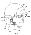
- Figure 12 shows an embodiment of a night vision device in accordance with the
invention.
-
DETAILED DESCRIPTION OF PREFERRED EMBODIMENTS
-
Figures 1 to 3 depict the prior art panoramic night vision goggles disclosed
in U.S. Patent No. 6,075,644, which is mentioned above. Referring to
Figures 1 and 2, it is seen that the goggles are comprised of a pair of housings
54 and 56 which are connected by a bridge 57, wherein each housing is for
covering a respective eye of an observer. Housing 54 (housing 56 is similar)
includes two separate optical channels 62 and 64, having an identical structure.
Optical channel 62 includes three main structures, which are an objective optical
system 66, an image intensifier tube 68, and an eyepiece optical train 70.
To illustrate the complexity, the objective optical system includes approximately
two to seven optical elements, while the eyepiece optical train also includes approximately
two to seven optical elements. Optical channels 62 and 64 are offset
by 30° from each other.
-
The overall device thus comprises four optical channels looking at three
fields of view, wherein each optical channel includes a large number of optical
elements and the optical system is folded (Figure 2). The field of view of the
four channels is shown schematically in Figure 3, and is seen to comprise a
binocular portion 106 sandwiched between two monocular portions 102 and
104, with the overall field measuring 100° horizontally by 40° vertically.
-
As previously mentioned, the prior art night vision device depicted in Figures
1 to 3 has significant disadvantages, including its relatively large weight
and volume and the long forward projection caused by the multiplicity of optical
components of which it is comprised.
-
In distinction to the prior art, in the preferred embodiment the present invention
utilizes video displays and compact prism eyepieces to achieve a panoramic
display. In a compact prism eyepiece, interactions of light with prism surfaces
are utilized, with the curvatures of the surfaces producing the requisite
optical powers to make the image appear at infinity. The term compact prism
eyepiece as used herein means each and every embodiment of such eyepieces
disclosed in U.S. Patent No. 5,701,202, the entire disclosure of which is incorporated
herein by reference.
-
Figure 4 depicts an embodiment of a compact prism eyepiece 2 disclosed
in U.S. Patent No. 5,701,202. Advantages of such eyepieces are their
small size, and the fact that they are comprised of only a single optical element.
Also, they may be constructed of optical plastic, which has only 1 /2 to 1/4 the
density of the optical glass typically used in coaxial eyepieces. When this is
combined with the fact that only a single prism element is used, the savings in
weight and volume are significant.
-
In addition to compact prism eyepiece 2, Figure 4 shows image source 4,
for example a video display, and viewing region 6. The eyepiece 2 includes an
entrance surface 8, a surface 10 which serves as both a reflecting surface and
an exit surface, and a surface 12 which serves as a reflecting surface.
-
In the operation of the device, a bundle of light rays emitted from the image
source 4 is refracted by entrance surface 8 and is internally reflected by
surface 10 and then again internally reflected by surface 12. The ray bundle is
then incident on the surface 10 again, and is refracted thereby so as to be projected
to viewing region 6 where the observer's eye is located.
-
Figure 5 shows a compact prism eyepiece 20 situated in a display housing
22. A flat panel video display 24 is also located in the housing as well as a
display printed circuit board 26. The unit could be suspended from a headmount
assembly so that the compact prism eyepiece would be slightly forward
of a user's eye in about the position of an eyeglass lens, and the entire unit
could have a minimal forward projection of only about 2,5 cm (one inch).
-
This is to be contrasted with a prior art coaxial type eyepiece 28 shown in
Figure 6. In this Figure, the eyepiece barrel 29 is broken away to show a few of
the lens train components 30, 31, 32 and 33. The prior art eyepiece, as discussed
above is much bulkier and heavier, and typically would have a forward
projection of about 7,5 cm (3 inches) from the eye.
-
An embodiment of the present invention is depicted in Figure 7. It is
comprised of two image sources 40 and 42, two compact prism eyepieces 44
and 46, and a viewing region 48. The image sources 40 and 42 may be video
displays, for example, microdisplays of small dimension.
-
The compact prism eyepieces receive image information from the image
sources, and the compact prism eyepieces are positioned in relation to each
other such that the images which are projected thereby are juxtaposed at viewing
region 48. The eyepieces 44 and 46 are adjacent each other along surfaces
110 and 112, and may abut each other, e.g. at the bottom of such surfaces as
shown in Figure 7. The image sources 40 and 42 are angled with respect to
prism entrance surfaces 114 and 116 so that an appropriate ray projection is
achieved.
-
In an actual embodiment, an observer's eye would be situated at viewing
region 48. The device could be stationary or portable. If portable, such as in a
video enhanced night vision device, the compact prisms (and video displays)
could be suspended from an observer's head with the compact prisms in about
the position of an eyeglass lens.
-
In some embodiments, the image information from the image sources is
intended to be juxtaposed by its content, for example when a panoramic view
of a single scene is desired. In other embodiments, a juxtaposition may be created
to achieve a certain effect, e.g. a first image may be of a scene, while a
second image juxtaposed with the first may be data or explanatory information
relevant to the scene. Figure 8 shows what two juxtaposed images may look
like when the images are respective parts of the same scene or pattern.
-
Figure 9 shows a further embodiment of the invention wherein the compact
prism eyepieces 120 and 122 are oriented vertically rather than horizontally.
The same effect as in Figure 7 is achieved, wherein the images projected
by the respective prisms from displays 126 and 128 are juxtaposed at viewing
region 124. In the particular embodiment shown, the prisms abut each other
along a vertically extending seam beginning at the top in Figure 9 at reference
numeral 129. The prisms abut only along a vertically extending line. The prisms
may be shaped to cause a greater degree of abutment and/or to cause other
edges to abut. In a portable embodiment, such as when part of a video night
vision device, the eyepieces could be suspended in front of a viewer's eye.
-
Referring to Figure 7 and 9, it is seen that the video displays are physically
smaller than the prisms, i.e. the cross-sectional area of display surface 65
is smaller than the cross-sectional area of prism entrance surface 66. Since the
prisms are larger than the displays it is possible to trim the prisms at angles
(both horizontally and vertically) so that the sides of a prism can abut the next
prism without causing the video displays to collide or interfere with each other in
any way.
-
Figure 10 shows a view of the Figure 9 embodiment looking at the prism
faces which abut each other at seam 129. The orientation of displays 126 and
128, as well as converging rays 127 as projected on a single plane, are shown.
-
Figure 11 shows a further embodiment of the invention wherein three
compact prism eyepieces 130, 132 and 134 are tiled together to achieve an
even wider field of view at viewing region 136, than in the embodiment of Figure
9. Vertically extending seam 137 is present. It is thus seen that the compact
prism eyepieces afford flexibility in how they can be tiled together by cutting
along different surfaces to achieve fields of view of varying dimensions and
shapes.
-
Figure 12 shows an embodiment of night vision goggles in accordance
with the invention. The viewer wears a head mount such as helmet 140, to
which the various components are secured. In lieu of a helmet, a head mount
assembly comprised of a mounting platform and head and neck straps may be
used.
-
The embodiment shown utilizes two image intensified video cameras 152
and 154 for the right eye, which respectively feed video signals by an electrical
connection to video display units 144 and 142. Each video camera includes an
image intensifier tube for amplifying low level visible and infrared light. Each of
the display units 142 and 144 is similar to the display unit depicted in Figure 5.
Display unit 142 contains a display and compact prism eyepiece 156, while display
unit 154 contains a display and compact prism eyepiece 158. The displays
and compact prism eyepieces are in the configuration shown in Figure 9, for
providing a wide angle view to the right eye. As can be seen, the video cameras
152 and 154 are oriented to be at an angle to each other, so as to cover a
panoramic field of view.
-
The video cameras may be mounted to helmet portion 150, which extends
below the right ear while the displays would be suspended in front of the
viewers eye(s), at or slightly ahead of where an eyeglass lens would be.
-
In the embodiment shown, display units 146 and 148 are suspended in
front of the left eye. These would be fed by a pair of image intensified video
cameras adjacent the left cheek (not shown). A night vision goggle may utilize
displays in front of one or both eyes, and the number of displays in front of each
eye may be at least two. The night vision device may be battery powered, and
may incorporate image processing. It is advantageous in comparison to prior
art panoramic night vision devices (e.g., Figures 1 to 3), in that it has a much
shorter profile, is lower in weight and volume, and enables the viewer a greater
amount of mobility. It also may be interfaced with other electronic equipment to
provide the viewer more information than direct view goggles.
-
There thus has been disclosed an improved wide angle display device
and panoramic video enhanced night vision goggle. While preferred and illustrative
embodiments of the invention have been disclosed, it should be understood
that variations will occur to those skilled in the art. Thus the invention to
be covered is set forth in the following claims.