EP0881812B1 - Telephone communication method capable of relating a telephone terminal and a speech channel IP address at the time of call connection - Google Patents
Telephone communication method capable of relating a telephone terminal and a speech channel IP address at the time of call connection Download PDFInfo
- Publication number
- EP0881812B1 EP0881812B1 EP19980109541 EP98109541A EP0881812B1 EP 0881812 B1 EP0881812 B1 EP 0881812B1 EP 19980109541 EP19980109541 EP 19980109541 EP 98109541 A EP98109541 A EP 98109541A EP 0881812 B1 EP0881812 B1 EP 0881812B1
- Authority
- EP
- European Patent Office
- Prior art keywords
- gateway
- communication connection
- telephone
- address
- telephone terminal
- Prior art date
- Legal status (The legal status is an assumption and is not a legal conclusion. Google has not performed a legal analysis and makes no representation as to the accuracy of the status listed.)
- Expired - Lifetime
Links
Images


Classifications
-
- H—ELECTRICITY
- H04—ELECTRIC COMMUNICATION TECHNIQUE
- H04L—TRANSMISSION OF DIGITAL INFORMATION, e.g. TELEGRAPHIC COMMUNICATION
- H04L12/00—Data switching networks
- H04L12/02—Details
- H04L12/16—Arrangements for providing special services to substations
- H04L12/18—Arrangements for providing special services to substations for broadcast or conference, e.g. multicast
-
- H—ELECTRICITY
- H04—ELECTRIC COMMUNICATION TECHNIQUE
- H04M—TELEPHONIC COMMUNICATION
- H04M7/00—Arrangements for interconnection between switching centres
- H04M7/006—Networks other than PSTN/ISDN providing telephone service, e.g. Voice over Internet Protocol (VoIP), including next generation networks with a packet-switched transport layer
-
- H—ELECTRICITY
- H04—ELECTRIC COMMUNICATION TECHNIQUE
- H04L—TRANSMISSION OF DIGITAL INFORMATION, e.g. TELEGRAPHIC COMMUNICATION
- H04L61/00—Network arrangements, protocols or services for addressing or naming
- H04L61/45—Network directories; Name-to-address mapping
- H04L61/4505—Network directories; Name-to-address mapping using standardised directories; using standardised directory access protocols
- H04L61/4511—Network directories; Name-to-address mapping using standardised directories; using standardised directory access protocols using domain name system [DNS]
-
- H—ELECTRICITY
- H04—ELECTRIC COMMUNICATION TECHNIQUE
- H04L—TRANSMISSION OF DIGITAL INFORMATION, e.g. TELEGRAPHIC COMMUNICATION
- H04L61/00—Network arrangements, protocols or services for addressing or naming
- H04L61/45—Network directories; Name-to-address mapping
- H04L61/4535—Network directories; Name-to-address mapping using an address exchange platform which sets up a session between two nodes, e.g. rendezvous servers, session initiation protocols [SIP] registrars or H.323 gatekeepers
-
- H—ELECTRICITY
- H04—ELECTRIC COMMUNICATION TECHNIQUE
- H04L—TRANSMISSION OF DIGITAL INFORMATION, e.g. TELEGRAPHIC COMMUNICATION
- H04L61/00—Network arrangements, protocols or services for addressing or naming
- H04L61/50—Address allocation
- H04L61/5007—Internet protocol [IP] addresses
-
- H—ELECTRICITY
- H04—ELECTRIC COMMUNICATION TECHNIQUE
- H04L—TRANSMISSION OF DIGITAL INFORMATION, e.g. TELEGRAPHIC COMMUNICATION
- H04L61/00—Network arrangements, protocols or services for addressing or naming
- H04L61/50—Address allocation
- H04L61/5076—Update or notification mechanisms, e.g. DynDNS
Definitions
- the present invention relates to a telephone communication method for a communication system allowing a plurality of telephone terminals to communicate via Internet or Intranet (Private IP (Internet Protocol) Network).
- Internet or Intranet Prior IP (Internet Protocol) Network
- Speech communication systems implemented by Internet include an IRC (Internet Relay Chat) server system referred to as Internetphone.
- IRC Internet Relay Chat
- a conventional telephone communication system using the IRC server system accommodates a number of gateways capable of accessing Internet. Telephone terminals are connected to each of the gateways via respective subscriber lines so as to allow conversation to be held therebetween.
- a number server is connected to Internet and assigns a particular IP (Internet Protocol) address to the telephone number of each telephone terminal for a control purpose.
- IP Internet Protocol
- a gateway Before a telephone connection, a gateway requests entry registration for a telephone service of the number server.
- the number server assigns a particular IP address to each telephone accommodated in the gateway. Assume that after the assignment of the IP addresses one of the telephone terminals accommodated in the gateway sends a call request meant for another telephone terminal to the gateway. Then, the gateway inquires the number server of an IP address assigned to the telephone to be called. In response, the number server searches for the above IP address and sends it to the gateway.
- the gateway having received the IP address sends a call connection request to a gateway accommodating the telephone terminal designated by the IP address. As a result, the call is terminated at the telephone terminal to be called.
- the called telephone terminal sends an answer representative of the call connection to the gateway accommodating the calling telephone terminal via the gateway accommodating the called telephone terminal. Consequently, the calling terminal and called terminal are connected together and allowed to communicate with each other.
- the conventional telephone communication procedure described above has the following problems left unsolved.
- H.323 (11/96); Visual telephone systems and equipment for local area networks which provide a non guaranteed quality of service, 1996-11-01, XP017401468, ITU-T recommendation H.323 is disclosed which describes terminals, equipment and services for multimedia communication over Local Area Networks (LAN) which do not provide a guaranteed quality of service.
- H.323 terminals and equipment may carry real-time voice, data and video, or any combination, including videotelephony.
- LAN over which H.323 terminals communicate may be a single segment or ring, or it may be multiple segments with complex topologies.
- H.323 terminals may be integrated into personal computers or implemented in stand-alone devices such as videotelephones. Support for voice is mandatory, while data and video are optional. But if supported, the ability to use a specified common mode of operation is required, so that all terminals supporting that media type can interwork.
- a voice communication system is provided by US 5,604,737 , which is connected to a LAN to which communication terminals are connected and to a public network to which telephones are connected, is provided with a communication server between the LAN and public network having different protocols from each other.
- the communication server enables a voice communication between a telephone on the public network and a communication terminal connected to the LAN by performing processing similar to that for a voice communication between two communication terminals connected to the LAN.
- the communication server determines whether an address of the other party inputted by a user is a communication terminal address or a telephone number, and transmits a voice communication request to a communication terminal of the other party when the address is a communication terminal address.
- the user acquires the communication terminal address of the communication server, and transmits a voice communication request to the communication server. Thereafter, the voice communication processing is performed through the communication server.
- a telephone communication method is applicable to a network system including a plurality of gateways given respective IP addresses corresponding to the addresses of Internet, which includes a control line having a first and a second channel and a speech line having a first and a second channel, for holding communication with each other via Internet on the basis of the IP addresses, and a plurality of telephone terminals given respective telephone numbers for holding communication with each other via the gateways on the basis of the telephone numbers.
- the method begins with the step of preparing a name server connectable to the gateways via Internet for managing the names of the gateways, IP addresses respectively corresponding to the names, and office numbers respectively assigned to the gateways.
- a first gateway accommodating the first telephone terminal is caused to access the name server via the first channel of the control line in response to a call originated on the first telephone terminal, and inquire the name server of the IP address of the second gateway by using the name corresponding to the office number assigned to the second gateway.
- the name server sends the IP address of the second gateway to the first gateway on the first channel of the control line.
- the first gateway selects the IP address of the speech line connected thereto and sends a call connection request to the second gateway on the second channel of the control line.
- the second gateway determines whether or not the second telephone terminal is busy, selects, if the second telephone terminal is idle, the IP address of the speech line, and returns the IP address selected to the first gateway, thereby setting up a connection between the first telephone terminal and the second telephone terminal.
- the first gateway transfers a speech signal received from the first telephone terminal to the second gateway on the speech line, and causes the second gateway to send the speech signal to the second telephone terminal.
- a telephone communication method is applicable to a network system including a plurality of gateways given respective IP addresses corresponding to the addresses of Internet, which includes a control line having a first and a second channel and a speech line having a first and a second channel, for holding communication with each other via Internet on the basis of the IP addresses, a plurality of switching systems given respective office numbers for holding communication with each other via the gateways on the basis of the office numbers, and a plurality of telephone terminals given respective telephone numbers for holding communication with each other via the gateways and switching systems on the basis of the telephone numbers.
- the method begins with the step of preparing a name server connected to the gateways via Internet for managing office numbers and names respectively given to the switching systems and IP addresses assigned to the gateways to which the switching systems are respectively connected.
- Subscriber data tables each is stored in a respective one of the gateways and has a division field storing division data showing whether an apparatus accommodated in the respective gateway is the telephone terminal or the switching system, and an office number field storing an office number assigned to the gateway and an office number assigned to the switching system accommodated in the gateway.
- a first gateway accommodating the first telephone terminal accesses the name server via the first channel of the control line in response to a call originated on the first telephone terminal and a call originated on a first switching system accommodating the first telephone terminal, and inquire the name server of the IP address of a second gateway accommodating a second switching system accommodating the second telephone terminal by using the name corresponding to the office number assigned to the second switching system.
- the name server sends the IP address of the second gateway to the first gateway on the first channel of the control line.
- the first gateway selects the IP address of the speech line connected thereto and sends a connection request to the second gateway on the second channel of the control line.
- the second gateway searches division data of the subscriber data and searches for, if the division data is representative of a switching system, the line of a switching system at which the office number of the second switching system and the office number included in the subscriber data coincide.
- the second gateway having detected the line of the switching system determines whether or not the line of the switching system is busy, selects, if the line is idle, the IP address of the speech line, and return the IP address selected to the first gateway, thereby setting up a connection between the first switching system and the second switching system and therefore between the first telephone terminal and the second telephone terminal.
- the first gateway transfers a speech signal received from the first telephone terminal via the first switching system to the second gateway via the speech line, and then the second gateway sends the speech signal to the second telephone terminal via the second switching system.
- a telephone communication system implemented by a telephone communication method embodying the present invention includes gateways (GW) 12 and 14 connected to Internet or Intranet 13 by respective connection lines 18 so as to access it, as needed.
- GW gateways
- the gateways 12 and 14 respectively accommodate telephone terminals 11 and 15 connected thereto by subscriber lines 17.
- the two telephone terminals 11 and 15 each is representative of a number of telephone terminals connected to the gateway 12 or 14. That is, the illustrative embodiment is, of course, applicable to a telephone communication system including other gateways and other telephone terminals.
- the gateway 12 converts an analog speech signal received from the telephone terminal 11 to a corresponding digital signal or converts a digital signal received via Internet or Intranet 13 to a corresponding analog signal and delivers the analog signal to the terminal 11.
- the gateway 12 executes various kinds of control over connections to occur via Internet or Intranet 13.
- the gateway 14 has exactly the same functions as the gateway 12 except that it deals with the telephone terminal 14.
- the gateways 12 and 14 may have an identical configuration as will be described later with reference to FIG. 2 .
- a DNS server or similar name server 16 is also connected to Internet or Intranet 13.
- the DNS server 16 has an address mapping function for managing correspondence between host names assigned to various hosts including the telephone terminals 11 and 15, gateways 12 and 14 and computers, not shown, and IP addresses.
- the DNS server 16 includes a memory, not shown, storing data representative of correspondence between the host names and the IP addresses in the form of a table
- FIG. 2 shows a specific configuration of the gateway 12 or 14.
- the gateway 12 or 14 includes a terminal accommodating circuit (Analog Peripheral Interface or APIF) 122.
- a group of lines including the lines to which the telephone terminal 11 or 15 is connected are connected to the input ports of the terminal accommodating circuit 122.
- the circuit 122 interfaces the group of lines 121 and the gateway 12 or 14.
- the circuit 122 has its output ports 129 connected to the input ports of a switch (SW) 123.
- SW switch
- the switch 123 selects one of the lines 121 at a time and connects it to its output port 130 which is connected to a voice compression controller (VCC) 124.
- VCC voice compression controller
- the voice compression controller 124 compresses a speech signal and then delivers it to a line 131 connected to Internet or Intranet 13, or reproduces a speech signal from a signal received from another gateway, as needed.
- the connection line 131 connected to the voice compression controller 124 is exclusively assigned to digital speech signals to be interchanged via Internet or Intranet 13.
- the gateway 12 further includes a LAN (Local Area Network) controller (LACM) 125 for sending various control signals particular to Internet or Intranet 13 to Internet or Intranet 13.
- LACM Local Area Network
- a control line 132 is connected to the LAN controller 125 in order to allow control information to be sent via Internet or Intranet 13.
- the gateway 12 or 14 additionally includes a central controller 126 for controlling call connections, and a memory 127 for storing number conversion information, which will be described, under the control of the central controller 126.
- the terminal accommodating circuit 122, switch 123, speech compression controller 124, LAN controller 125, central controller 126 and memory 127 are interconnected by a bus 128, as illustrated.
- FIG. 3 shows a specific configuration of the central controller 126 for implementing the gateway control function.
- the central controller 126 includes a call control (CPC) 1261 for processing call connections between a source apparatus and a destination apparatus, e.g., between the gateways 12 and 14 and therefore between the telephone terminals 11 and 15.
- Line controls (CCC) 1262 are connected to the call control 1261, as illustrated.
- the line controls 1262 execute the line-by-line access of the gateway 12 or 14 to the DNS server 16 and commands voice compression and control over a speech path.
- a LAN control (LAC) 1263 is also connected to the call control 1261, as illustrated.
- the LAN control 1263 controls the LAN controller 125 in order to interchange control information via Internet or Intranet 13.
- a DNS control (DNSC) 1264, a voice compression control (VCC) 1265 and speech path control (SPC) 1266 are connected to the line control 1262, as illustrated.
- the DNS control 1264 controls number inquiry to the DNS server 16.
- the voice compression control 1265 controls the compression and reproduction of speech signals to be executed by the speech compression controller 124.
- the speech path control 1266 controls the terminal accommodating circuit 122 and switch 123 in order to selectively set up or interrupt the connection path between the telephone terminals 11 and 15 and the connection path between the terminal 11 and the voice compression controller 124.
- FIG. 4 shows specific number conversion information stored in the DNS server 16 of the illustrative embodiment.
- the number conversion information are based on rules prescribed by RFC (Request For Comments) 1034 (Domain Names - Concepts and Facilities).
- the gateways 12 and 14 are assumed to be respectively located in Tokyo and Osaka, Japan, and respectively provided with office numbers of "30" and "60".
- the gateways 12 and 14 are provided with host names "TOKYO" and "OSAKA”, respectively.
- the control lines 132 of Internet 1 3 connected to the gateways 12 and 14, respectively, are provided with IP addresses "133. 149. 30. 16" and "133. 149. 60. 16", respectively.
- the IP addresses are respectively related to the host names first, and then the office numbers "30" and "60” are respectively assigned to the host names as double definition, i.e., CNAMEs (Canonical Names).
- the gateways 12 and 14 each is capable of accessing the DNS server 16 via a UDP (User Datagram Protocol) channel 141 included in the respective control line 132 belonging to Internet or Intranet 13.
- the DNS server 16 provides, e.g., the gateway 12 with the office number, host name and IP address of, e.g., the gateway 14.
- the gateway 12 confirms the status of the telephone terminal designated by the office number, host name and IP address, i.e., the telephone terminal 14 via a TCP (Transmission Control Protocol) channel 142 included in the associated control line 132.
- TCP Transmission Control Protocol
- the gateway 12 selects an IP address assigned to the speech line 131 belonging to Internet or Intranet 13. As a result, a speech signal is sent via a UDP channel 143 on the IP address of the speech line 131 selected.
- the gateway 12 monitors the UDP channel 143 via the TCP channel 142 of the same address as the channel 143. In this manner, at the time of call connection, the illustrative embodiment relates the telephone terminal 15 and the IP address of the UDP channel 143 to each other. This obviates the need for the conventional assignment of a particular IP address to each telephone terminal.
- FIG. 6 demonstrates a specific communication sequence available with the illustrative embodiment. How telephone communication is held in the above system will be described with reference to FIG. 6 .
- the gateway 11 causes its central controller 126 to control the LAN controller 125 in order to access the DNS server 16 via the UDP channel 141 of the control line 132.
- the LAN controller 125 inquires the DNS server 16 of the IP address of the gateway 14 to be called, using the host name corresponding to the office number of the gateway 14 accommodating the telephone terminal to be called (destination hereinafter) 15. This is represented by a flow 201.
- the DNS server 16 searches its table listing the correspondence between the host names and IP addresses, using the host name "OSAKA". In this case, the DNS server 16 reads the IP address "133. 149. 60. 16" assigned to the gateway 14 to be called out of the table and returns it to the LAN controller 125 of the gateway 12 over the UDP channel 141 of the control line 132. Such a response of the DNS server 16 is represented by a flow 202.
- the LAN controller 125 of the gateway 12 designates the IP address of the gateway 14 on the speech line 131 under the control of the central controller 126. Then, the LAN controller 125 sends a call connection request 203 to the gateway 14 over the TCP channel 142 of the control line 132 having the above IP address.
- the central controller 126 of the called gateway 14 determines whether or not the destination 15 is busy. If the destination 15 is busy, then the central controller 126 returns a message representative of the busy state to the calling gateway 12. This message is transferred to the call control 1261 of the calling gateway 12 via the LAN controller 125 and the LAN control 1263 of the central controller 126. On the other hand, if the destination 15 is idle, the central controller 126 of the called gateway 14 causes the destination 15 to ring or otherwise display a call incoming 204. When a person at the telephone terminal 15 off-hooks the terminal 15 to answer the phone, the central controller 126 of the called gateway 14 detects the response 205 and then selects the IP address of the speech line 131.
- the IP address selected is sent to the calling gateway 12 in the form of a response message 206.
- the call control 1261 receives the response message 206.
- a response 207 representative of the response from the destination 15 is sent to the source 11 in order to set up call connection between the source 11 and the destination 15.
- the speech compression circuit 124 of the gateway 12 compresses the speech signal under the control of the central controller 126.
- the compressed speech signal is sent from the calling gateway 12 to the called gateway 14 on the speech channel of the speech line 131, i.e., the UDP channel 143.
- the voice compression controller 124 reproduces an analog speech signal from the compressed speech signal and sends it to the destination 15.
- a speech signal is sent from the destination 15 to the source 11 in exactly the same way. In this manner, conversation 207 is held between the source 11 and the destination 15.
- a telephone terminal and the IP address of a UDP channel for speech transfer are related to each other first. It is, therefore, not necessary to assign a particular IP address to each telephone terminal by use of the entry registration principle. This allows a plurality of terminals to share a single IP address and thereby promotes the efficient use of the limited number of IP addresses. Further, because telephone terminals do not have to be registered at a DNS server, they can be used for emergency calls. In addition, speech communication can be implemented by a DNS server customarily connected to a data network, i.e., without resorting to a special address server.
- FIG. 7 an alternative embodiment of the present invention will be described.
- reference numerals identical with the reference numerals shown in FIG. 1 denote like structural elements.
- this embodiment differs from the previous embodiment in that private branch exchanges (PBXs) or switching systems 11A and 15A are respectively connected between the telephone terminal 11 and the gateway 12 and between the telephone terminal 15 and the gateway 14.
- PBXs private branch exchanges
- switching systems 11A and 15A are respectively connected between the telephone terminal 11 and the gateway 12 and between the telephone terminal 15 and the gateway 14.
- this embodiment is identical with the previous embodiment.
- the DNS server 16 stores number conversion information in a specific format shown in FIG. 8 .
- the gateways 12 and 14 accommodating the PBXs 11A and 15A, respectively are assumed to be located in Tokyo and Osaka, respectively.
- the office numbers "30" and "60” are assigned to the PBXs 11A and 15A, respectively.
- host names "TOKYOPBX” and "OSAKAPBX” are given to the PBXs 11A and 15A, respectively.
- the IP addresses of the control lines 132 of Internet or Intranet 13 connected to the gateways 12 and 14, respectively, are "133. 149. 30. 16" and "133. 149. 60. 16", respectively.
- such IP addresses are respectively related to the host names first, and then the PBX office numbers are respectively assigned to the host names as double definition, i.e., CNAMEs.
- the gateways 12 and 14 each stores subscriber data.
- the subscriber data are stored in the memories 127 of the gateways 12 and 14 in a specific format shown in FIG. 9 .
- the format is made up of a division field 210, an office number field 211, and an extension number field 212.
- a (logical) ZERO is set if the apparatus accommodated in the gateway 12 or 14 is an extension, or a (logical) ONE is set if it is a private branch exchange.
- the office number assigned to the gateway 12 or 14 is set if the apparatus set in the division field 210 is an extension, or the office number assigned to a private branch exchange is set if it is a private branch exchange. Further, in the extension number field 212, an extension number is set if the apparatus set in the division field 210 is an extension.
- the telephone terminal (source hereinafter) 11 in Tokyo outputs a connection request 200 meant for the telephone terminal (destination hereinafter) 15 in Osaka.
- the PBX 11A accommodating the source 15 sends a call 200a to the gateway 12.
- the LAN controller 125 accesses the DNS server 16 via the UDP channel 141 of the control line 132, FIG. 5 , under the control of the central controller 126, FIG. 2 .
- the LAN controller 125 inquires the DNS server 16 of the IP address of the gateway 14 accommodating the PBX 15A, using the host name "OSAKAPBX" corresponding to the office number of the destination 15 (flow 201). This is followed by the response-to-call procedure (2) and call connection request procedure (3) described previously with reference to FIG. 6 .
- the DNS server 16 searches for the IP address of the called gateway 14 and returns it to the calling gateway 12.
- the gateway 12 designates the IP address of the gateway 14 on the speech line 131, FIG. 5 , and then sends a call connection request 203 to the gateway 14 on the TCP channel 142, FIG. 5 , of the control line designated by the above IP address.
- the called gateway 14 On receiving the call connection request 203, the called gateway 14 causes its central controller 126 to search the subscriber data stored in the memory 127.
- the central controller 126 determines the kind of an apparatus set in the division field 210 of the subscriber data searched for. If the apparatus is a private branch exchange, then the controller 126 identifies the line of a private branch exchange whose office number ("60" in this case) is identical with the data stored in the office number field 211 of the subscriber data 127.
- the central controller 126 In the called gateway 14, the central controller 126 having detected the line to the PBX 15A determines whether or not the PBX line is busy. If the PBX line is busy, then the central controller 126 returns a message representative of the busy state to the calling gateway 12. If the PBX line is idle, then the central controller 126 of the called gateway 14 causes the PBX 15A and destination 15 to display a call incoming 204 and a call incoming 204a, respectively. When a person at the destination off-hooks the telephone terminal 15 to answer the phone, the terminal 15 and PBX 15A respectively return responses 205 and 205a to the called gateway 14. The central controller 126 of the called gateway 14 detects the response 205a and then selects the IP address of the speech line 131.
- the IP address selected is sent to the calling gateway 12 in the form of a response message 206.
- the call control 1261 receives the response message 206.
- a response 207 representative of the response from the destination 15 is sent to the PBX 11A which, in turn, sends a response 207a to the source 11 in order to set up call connection between the source 11 and the destination 15.
- the speech compression circuit 124 of the gateway 12 compresses the speech signal under the control of the central controller 126.
- the compressed speech signal is sent from the calling gateway 12 to the called gateway 14 on the speech channel of the speech line 131, i.e., the UDP channel 143.
- the voice compression controller 124 reproduces an analog speech signal from the compressed speech signal and sends it to the destination 15 via the PBX 15A.
- a speech signal is sent from the destination 15 to the source 11 in exactly the same way. In this manner, conversation 208 is held between the source 11 and the destination 15.
- the DNS server 16 manages office numbers respectively assigned to the PBXs 11A and 15A, names respectively given to the PBXs 11A and 15A, and IP addresses respectively assigned to the gateways 12 and 14 accommodating the PBXs 11A and 15A, respectively.
- the gateways 12 and 14 each stores the subscriber data table 127 for managing the subscriber data including the division field 210 and office number field 211.
- the division field 210 stores data showing whether an apparatus accommodated is a telephone terminal or an exchange.
- the office number field 211 stores the office number of the gateway 12 or 14 and the office number of the associated PBX 11A or 15A.
- the present invention provides a telephone communication method capable of relating a telephone terminal and the IP address of a speech transfer channel to each other. This obviates the need for the conventional assignment of a particular IP address to each telephone terminal and allows a plurality of telephone terminals to share a single IP address. Therefore, the method of the invention promotes the efficient use of the limited number of IP addresses. In addition, the method of the invention allows a telephone communication system using Internet to be used for emergency calls because it does not register telephone terminals at a name server.
Description
- The present invention relates to a telephone communication method for a communication system allowing a plurality of telephone terminals to communicate via Internet or Intranet (Private IP (Internet Protocol) Network).
- Speech communication systems implemented by Internet include an IRC (Internet Relay Chat) server system referred to as Internetphone. A conventional telephone communication system using the IRC server system accommodates a number of gateways capable of accessing Internet. Telephone terminals are connected to each of the gateways via respective subscriber lines so as to allow conversation to be held therebetween. A number server is connected to Internet and assigns a particular IP (Internet Protocol) address to the telephone number of each telephone terminal for a control purpose.
- Before a telephone connection, a gateway requests entry registration for a telephone service of the number server. In response to the request, the number server assigns a particular IP address to each telephone accommodated in the gateway. Assume that after the assignment of the IP addresses one of the telephone terminals accommodated in the gateway sends a call request meant for another telephone terminal to the gateway. Then, the gateway inquires the number server of an IP address assigned to the telephone to be called. In response, the number server searches for the above IP address and sends it to the gateway. The gateway having received the IP address sends a call connection request to a gateway accommodating the telephone terminal designated by the IP address. As a result, the call is terminated at the telephone terminal to be called. The called telephone terminal sends an answer representative of the call connection to the gateway accommodating the calling telephone terminal via the gateway accommodating the called telephone terminal. Consequently, the calling terminal and called terminal are connected together and allowed to communicate with each other.
- The conventional telephone communication procedure described above has the following problems left unsolved. First, while a particular IP address must be assigned to each telephone terminal, communication will become difficult in the future because the number of IP addresses is limited and short throughout the world. Second, the communication system inhibits communication from being held on telephone terminals other than those registered at the number server, so that it is not available for emergency calls.
- In ITU-T STANDARD SUPERSEDED (S), INTERNATIONAL TELECOMMUNICATION UNION, GENEVA,, CH, Packet-based multimedia communication systems; H.323 (11/96); Visual telephone systems and equipment for local area networks which provide a non guaranteed quality of service, 1996-11-01, XP017401468, ITU-T recommendation H.323 is disclosed which describes terminals, equipment and services for multimedia communication over Local Area Networks (LAN) which do not provide a guaranteed quality of service. H.323 terminals and equipment may carry real-time voice, data and video, or any combination, including videotelephony. Then LAN over which H.323 terminals communicate, may be a single segment or ring, or it may be multiple segments with complex topologies. It should be noted that operations of H.323 terminals over the multiple LAN segments (including the Internet) may result in poor performance. H.323 terminals may be integrated into personal computers or implemented in stand-alone devices such as videotelephones. Support for voice is mandatory, while data and video are optional. But if supported, the ability to use a specified common mode of operation is required, so that all terminals supporting that media type can interwork.
- A voice communication system is provided by
US 5,604,737 , which is connected to a LAN to which communication terminals are connected and to a public network to which telephones are connected, is provided with a communication server between the LAN and public network having different protocols from each other. The communication server enables a voice communication between a telephone on the public network and a communication terminal connected to the LAN by performing processing similar to that for a voice communication between two communication terminals connected to the LAN. The communication server determines whether an address of the other party inputted by a user is a communication terminal address or a telephone number, and transmits a voice communication request to a communication terminal of the other party when the address is a communication terminal address. When the address is a telephone number, the user acquires the communication terminal address of the communication server, and transmits a voice communication request to the communication server. Thereafter, the voice communication processing is performed through the communication server. - It is therefore an object of the present invention to provide a telephone communication method allowing a plurality of telephone terminals to share a single IP address and thereby promoting the efficient use of the limited number of IP addresses.
- It is another object of the present invention to provide a telephone communication method implementing a telephone communication system available even for emergency calls.
- The present invention is defined in the independent claims. The dependent claims form advantageous embodiments of the invention.
- A telephone communication method according to an embodiment of the present invention is applicable to a network system including a plurality of gateways given respective IP addresses corresponding to the addresses of Internet, which includes a control line having a first and a second channel and a speech line having a first and a second channel, for holding communication with each other via Internet on the basis of the IP addresses, and a plurality of telephone terminals given respective telephone numbers for holding communication with each other via the gateways on the basis of the telephone numbers. The method begins with the step of preparing a name server connectable to the gateways via Internet for managing the names of the gateways, IP addresses respectively corresponding to the names, and office numbers respectively assigned to the gateways.
- When a first telephone terminal outputs a connection request meant for a second telephone terminal, a first gateway accommodating the first telephone terminal is caused to access the name server via the first channel of the control line in response to a call originated on the first telephone terminal, and inquire the name server of the IP address of the second gateway by using the name corresponding to the office number assigned to the second gateway. The name server sends the IP address of the second gateway to the first gateway on the first channel of the control line. The first gateway selects the IP address of the speech line connected thereto and sends a call connection request to the second gateway on the second channel of the control line. The second gateway determines whether or not the second telephone terminal is busy, selects, if the second telephone terminal is idle, the IP address of the speech line, and returns the IP address selected to the first gateway, thereby setting up a connection between the first telephone terminal and the second telephone terminal. The first gateway transfers a speech signal received from the first telephone terminal to the second gateway on the speech line, and causes the second gateway to send the speech signal to the second telephone terminal.
- Also, a telephone communication method according to an embodiment of the present invention is applicable to a network system including a plurality of gateways given respective IP addresses corresponding to the addresses of Internet, which includes a control line having a first and a second channel and a speech line having a first and a second channel, for holding communication with each other via Internet on the basis of the IP addresses, a plurality of switching systems given respective office numbers for holding communication with each other via the gateways on the basis of the office numbers, and a plurality of telephone terminals given respective telephone numbers for holding communication with each other via the gateways and switching systems on the basis of the telephone numbers. The method begins with the step of preparing a name server connected to the gateways via Internet for managing office numbers and names respectively given to the switching systems and IP addresses assigned to the gateways to which the switching systems are respectively connected. Subscriber data tables each is stored in a respective one of the gateways and has a division field storing division data showing whether an apparatus accommodated in the respective gateway is the telephone terminal or the switching system, and an office number field storing an office number assigned to the gateway and an office number assigned to the switching system accommodated in the gateway.
- When a first telephone terminal outputs a connection request meant for a second telephone terminal, a first gateway accommodating the first telephone terminal accesses the name server via the first channel of the control line in response to a call originated on the first telephone terminal and a call originated on a first switching system accommodating the first telephone terminal, and inquire the name server of the IP address of a second gateway accommodating a second switching system accommodating the second telephone terminal by using the name corresponding to the office number assigned to the second switching system. The name server sends the IP address of the second gateway to the first gateway on the first channel of the control line. The first gateway selects the IP address of the speech line connected thereto and sends a connection request to the second gateway on the second channel of the control line. The second gateway searches division data of the subscriber data and searches for, if the division data is representative of a switching system, the line of a switching system at which the office number of the second switching system and the office number included in the subscriber data coincide. The second gateway having detected the line of the switching system determines whether or not the line of the switching system is busy, selects, if the line is idle, the IP address of the speech line, and return the IP address selected to the first gateway, thereby setting up a connection between the first switching system and the second switching system and therefore between the first telephone terminal and the second telephone terminal. The first gateway transfers a speech signal received from the first telephone terminal via the first switching system to the second gateway via the speech line, and then the second gateway sends the speech signal to the second telephone terminal via the second switching system.
- The objects and features of the present invention will become more apparent from the consideration of the following detailed description taken in conjunction with the accompanying drawings in which:
-
FIG. 1 is a block diagram schematically showing a telephone communication system to which a telephone communication method embodying the present invention is applied; -
FIG. 2 is a block diagram schematically showing a specific configuration of a gateway included in the embodiment shown inFIG. 1 ; -
FIG. 3 is a block diagram schematically showing a specific configuration of a central controller included in the gateway ofFIG. 2 ; -
FIG. 4 shows a specific format of number conversion information stored in a DNS (Domain Name System) server also included in the embodiment ofFIG. 1 ; -
FIG. 5 is a view useful for understanding channels included in Internet and used by the embodiment ofFIG. 1 ; -
FIG. 6 is a chart representative of a specific communication sequence available with the embodiment ofFIG. 1 ; -
FIG. 7 is a block diagram similar toFIG. 1 , schematically showing a telephone communication system to which an alternative embodiment of the present invention is applied; -
FIG. 8 is a view similar toFIG. 4 , showing a specific number conversion information particular to the embodiment shown inFIG. 7 ; -
FIG. 9 shows a specific format of subscriber data also particular to the embodiment shown inFIG. 7 ; and -
FIG. 10 is a chart demonstrating a specific communication sequence available with the embodiment shown inFIG. 7 . - Referring to
FIG. 1 of the drawings, a telephone communication system implemented by a telephone communication method embodying the present invention includes gateways (GW) 12 and 14 connected to Internet orIntranet 13 byrespective connection lines 18 so as to access it, as needed. It should be noted that, for simplicity inFIG. 1 the twogateways gateways telephone terminals subscriber lines 17. InFIG. 1 , the twotelephone terminals gateway - The
gateway 12 converts an analog speech signal received from thetelephone terminal 11 to a corresponding digital signal or converts a digital signal received via Internet orIntranet 13 to a corresponding analog signal and delivers the analog signal to the terminal 11. In addition, thegateway 12 executes various kinds of control over connections to occur via Internet orIntranet 13. Thegateway 14 has exactly the same functions as thegateway 12 except that it deals with thetelephone terminal 14. Thegateways FIG. 2 . - A DNS server or
similar name server 16 is also connected to Internet orIntranet 13. TheDNS server 16 has an address mapping function for managing correspondence between host names assigned to various hosts including thetelephone terminals gateways DNS server 16 includes a memory, not shown, storing data representative of correspondence between the host names and the IP addresses in the form of a table -
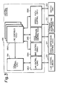
FIG. 2 shows a specific configuration of thegateway gateway 12. As shown, thegateway telephone terminal accommodating circuit 122. Thecircuit 122 interfaces the group oflines 121 and thegateway circuit 122 has itsoutput ports 129 connected to the input ports of a switch (SW) 123. Theswitch 123 selects one of thelines 121 at a time and connects it to itsoutput port 130 which is connected to a voice compression controller (VCC) 124. Thevoice compression controller 124 compresses a speech signal and then delivers it to aline 131 connected to Internet orIntranet 13, or reproduces a speech signal from a signal received from another gateway, as needed. Theconnection line 131 connected to thevoice compression controller 124 is exclusively assigned to digital speech signals to be interchanged via Internet orIntranet 13. - The
gateway 12 further includes a LAN (Local Area Network) controller (LACM) 125 for sending various control signals particular to Internet orIntranet 13 to Internet orIntranet 13. Specifically, acontrol line 132 is connected to theLAN controller 125 in order to allow control information to be sent via Internet orIntranet 13. Thegateway central controller 126 for controlling call connections, and amemory 127 for storing number conversion information, which will be described, under the control of thecentral controller 126. The terminalaccommodating circuit 122,switch 123,speech compression controller 124,LAN controller 125,central controller 126 andmemory 127 are interconnected by abus 128, as illustrated. -
FIG. 3 shows a specific configuration of thecentral controller 126 for implementing the gateway control function. As shown, thecentral controller 126 includes a call control (CPC) 1261 for processing call connections between a source apparatus and a destination apparatus, e.g., between thegateways telephone terminals call control 1261, as illustrated. The line controls 1262 execute the line-by-line access of thegateway DNS server 16 and commands voice compression and control over a speech path. A LAN control (LAC) 1263 is also connected to thecall control 1261, as illustrated. TheLAN control 1263 controls theLAN controller 125 in order to interchange control information via Internet orIntranet 13. - A DNS control (DNSC) 1264, a voice compression control (VCC) 1265 and speech path control (SPC) 1266 are connected to the
line control 1262, as illustrated. TheDNS control 1264 controls number inquiry to theDNS server 16. Thevoice compression control 1265 controls the compression and reproduction of speech signals to be executed by thespeech compression controller 124. The speech path control 1266 controls the terminalaccommodating circuit 122 and switch 123 in order to selectively set up or interrupt the connection path between thetelephone terminals voice compression controller 124. -
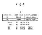
FIG. 4 shows specific number conversion information stored in theDNS server 16 of the illustrative embodiment. The number conversion information are based on rules prescribed by RFC (Request For Comments) 1034 (Domain Names - Concepts and Facilities). InFIG. 4 , thegateways gateways gateways - Specific channels available with Internet or
Intranet 13 will be described with reference toFIG. 5 . As shown, thegateways DNS server 16 via a UDP (User Datagram Protocol)channel 141 included in therespective control line 132 belonging to Internet orIntranet 13. TheDNS server 16 provides, e.g., thegateway 12 with the office number, host name and IP address of, e.g., thegateway 14. Then, thegateway 12 confirms the status of the telephone terminal designated by the office number, host name and IP address, i.e., thetelephone terminal 14 via a TCP (Transmission Control Protocol)channel 142 included in the associatedcontrol line 132. At the same time, thegateway 12 selects an IP address assigned to thespeech line 131 belonging to Internet orIntranet 13. As a result, a speech signal is sent via aUDP channel 143 on the IP address of thespeech line 131 selected. When thegateway 12 sends a speech signal via theUDP channel 143, it cannot confirm its connection to thedestination telephone terminal 15. For this reason, thegateway 12 monitors theUDP channel 143 via theTCP channel 142 of the same address as thechannel 143. In this manner, at the time of call connection, the illustrative embodiment relates thetelephone terminal 15 and the IP address of theUDP channel 143 to each other. This obviates the need for the conventional assignment of a particular IP address to each telephone terminal. -
FIG. 6 demonstrates a specific communication sequence available with the illustrative embodiment. How telephone communication is held in the above system will be described with reference toFIG. 6 . - Assume that the
telephone terminal 11 located in Tokyo outputs a connection request meant for thetelephone terminal 15 located in Osaka. In response to callorigination 200 on the telephone terminal (source hereinafter) 11, thegateway 11 causes itscentral controller 126 to control theLAN controller 125 in order to access theDNS server 16 via theUDP channel 141 of thecontrol line 132. Specifically, theLAN controller 125 inquires theDNS server 16 of the IP address of thegateway 14 to be called, using the host name corresponding to the office number of thegateway 14 accommodating the telephone terminal to be called (destination hereinafter) 15. This is represented by aflow 201. - In response to the
inquiry 201, theDNS server 16 searches its table listing the correspondence between the host names and IP addresses, using the host name "OSAKA". In this case, theDNS server 16 reads the IP address "133. 149. 60. 16" assigned to thegateway 14 to be called out of the table and returns it to theLAN controller 125 of thegateway 12 over theUDP channel 141 of thecontrol line 132. Such a response of theDNS server 16 is represented by aflow 202. - On receiving the
response 202, theLAN controller 125 of thegateway 12 designates the IP address of thegateway 14 on thespeech line 131 under the control of thecentral controller 126. Then, theLAN controller 125 sends acall connection request 203 to thegateway 14 over theTCP channel 142 of thecontrol line 132 having the above IP address. - In response to the
connection request 203, thecentral controller 126 of the calledgateway 14 determines whether or not thedestination 15 is busy. If thedestination 15 is busy, then thecentral controller 126 returns a message representative of the busy state to the callinggateway 12. This message is transferred to thecall control 1261 of the callinggateway 12 via theLAN controller 125 and theLAN control 1263 of thecentral controller 126. On the other hand, if thedestination 15 is idle, thecentral controller 126 of the calledgateway 14 causes thedestination 15 to ring or otherwise display a call incoming 204. When a person at thetelephone terminal 15 off-hooks the terminal 15 to answer the phone, thecentral controller 126 of the calledgateway 14 detects theresponse 205 and then selects the IP address of thespeech line 131. The IP address selected is sent to the callinggateway 12 in the form of aresponse message 206. In the callinggateway 12, thecall control 1261 receives theresponse message 206. As a result, aresponse 207 representative of the response from thedestination 15 is sent to thesource 11 in order to set up call connection between thesource 11 and thedestination 15. - As a speech signal is sent from the
source 11 to the callinggateway 12, thespeech compression circuit 124 of thegateway 12 compresses the speech signal under the control of thecentral controller 126. The compressed speech signal is sent from the callinggateway 12 to the calledgateway 14 on the speech channel of thespeech line 131, i.e., theUDP channel 143. In the calledgateway 14, thevoice compression controller 124 reproduces an analog speech signal from the compressed speech signal and sends it to thedestination 15. A speech signal is sent from thedestination 15 to thesource 11 in exactly the same way. In this manner,conversation 207 is held between thesource 11 and thedestination 15. - Advantages achievable with the illustrative embodiment are as follows. At the time of call connection, a telephone terminal and the IP address of a UDP channel for speech transfer are related to each other first. It is, therefore, not necessary to assign a particular IP address to each telephone terminal by use of the entry registration principle. This allows a plurality of terminals to share a single IP address and thereby promotes the efficient use of the limited number of IP addresses. Further, because telephone terminals do not have to be registered at a DNS server, they can be used for emergency calls. In addition, speech communication can be implemented by a DNS server customarily connected to a data network, i.e., without resorting to a special address server.
- Referring to
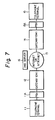
FIG. 7 , an alternative embodiment of the present invention will be described. InFIG. 7 , reference numerals identical with the reference numerals shown inFIG. 1 denote like structural elements. As shown, this embodiment differs from the previous embodiment in that private branch exchanges (PBXs) orswitching systems 11A and 15A are respectively connected between thetelephone terminal 11 and thegateway 12 and between thetelephone terminal 15 and thegateway 14. As for the rest of the construction, this embodiment is identical with the previous embodiment. - In this embodiment, the
DNS server 16 stores number conversion information in a specific format shown inFIG. 8 . As shown, thegateways PBXs 11A and 15A, respectively, are assumed to be located in Tokyo and Osaka, respectively. In the illustrative embodiment, the office numbers "30" and "60" are assigned to thePBXs 11A and 15A, respectively. Also, host names "TOKYOPBX" and "OSAKAPBX" are given to thePBXs 11A and 15A, respectively. The IP addresses of thecontrol lines 132 of Internet orIntranet 13 connected to thegateways - The
gateways memories 127 of thegateways FIG. 9 . As shown, the format is made up of adivision field 210, anoffice number field 211, and anextension number field 212. In thedivision field 210, a (logical) ZERO is set if the apparatus accommodated in thegateway office number field 211, the office number assigned to thegateway division field 210 is an extension, or the office number assigned to a private branch exchange is set if it is a private branch exchange. Further, in theextension number field 212, an extension number is set if the apparatus set in thedivision field 210 is an extension. - A specific telephone communication sequence available with the system shown in
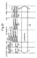
FIG. 7 will be described with reference toFIG. 10 . - Assume that the telephone terminal (source hereinafter) 11 in Tokyo outputs a
connection request 200 meant for the telephone terminal (destination hereinafter) 15 in Osaka. In response, the PBX 11A accommodating thesource 15 sends acall 200a to thegateway 12. In response, in thegateway 12, theLAN controller 125,FIG. 2 , accesses theDNS server 16 via theUDP channel 141 of thecontrol line 132,FIG. 5 , under the control of thecentral controller 126,FIG. 2 . TheLAN controller 125 inquires theDNS server 16 of the IP address of thegateway 14 accommodating thePBX 15A, using the host name "OSAKAPBX" corresponding to the office number of the destination 15 (flow 201). This is followed by the response-to-call procedure (2) and call connection request procedure (3) described previously with reference toFIG. 6 . - Specifically, the
DNS server 16 searches for the IP address of the calledgateway 14 and returns it to the callinggateway 12. In response, thegateway 12 designates the IP address of thegateway 14 on thespeech line 131,FIG. 5 , and then sends acall connection request 203 to thegateway 14 on theTCP channel 142,FIG. 5 , of the control line designated by the above IP address. - On receiving the
call connection request 203, the calledgateway 14 causes itscentral controller 126 to search the subscriber data stored in thememory 127. Thecentral controller 126 determines the kind of an apparatus set in thedivision field 210 of the subscriber data searched for. If the apparatus is a private branch exchange, then thecontroller 126 identifies the line of a private branch exchange whose office number ("60" in this case) is identical with the data stored in theoffice number field 211 of thesubscriber data 127. - In the called
gateway 14, thecentral controller 126 having detected the line to thePBX 15A determines whether or not the PBX line is busy. If the PBX line is busy, then thecentral controller 126 returns a message representative of the busy state to the callinggateway 12. If the PBX line is idle, then thecentral controller 126 of the calledgateway 14 causes thePBX 15A anddestination 15 to display a call incoming 204 and a call incoming 204a, respectively. When a person at the destination off-hooks thetelephone terminal 15 to answer the phone, the terminal 15 andPBX 15A respectively returnresponses 205 and 205a to the calledgateway 14. Thecentral controller 126 of the calledgateway 14 detects the response 205a and then selects the IP address of thespeech line 131. The IP address selected is sent to the callinggateway 12 in the form of aresponse message 206. In the callinggateway 12, thecall control 1261 receives theresponse message 206. As a result, aresponse 207 representative of the response from thedestination 15 is sent to the PBX 11A which, in turn, sends a response 207a to thesource 11 in order to set up call connection between thesource 11 and thedestination 15. - As a speech signal is sent from the
source 11 to the callinggateway 12 via the PBX 11A, thespeech compression circuit 124 of thegateway 12 compresses the speech signal under the control of thecentral controller 126. The compressed speech signal is sent from the callinggateway 12 to the calledgateway 14 on the speech channel of thespeech line 131, i.e., theUDP channel 143. In the calledgateway 14, thevoice compression controller 124 reproduces an analog speech signal from the compressed speech signal and sends it to thedestination 15 via thePBX 15A. A speech signal is sent from thedestination 15 to thesource 11 in exactly the same way. In this manner,conversation 208 is held between thesource 11 and thedestination 15. - As stated above, in the illustrative embodiment, the
DNS server 16 manages office numbers respectively assigned to thePBXs 11A and 15A, names respectively given to thePBXs 11A and 15A, and IP addresses respectively assigned to thegateways PBXs 11A and 15A, respectively. Thegateways division field 210 andoffice number field 211. Thedivision field 210 stores data showing whether an apparatus accommodated is a telephone terminal or an exchange. Theoffice number field 211 stores the office number of thegateway PBX 11A or 15A. With this configuration, the embodiment advantageously implements speechcommunication using Internet 13 not only via a telephone terminal but also via a private branch exchange belonging to a telephone network. Of course, it is not necessary for both of a source and a destination to communicate via respective private branch exchanges. - In a conventional system of the type including private branch exchanges respectively accommodated by the calling gateway 1 2 and called
gateway 14, it is necessary to register the telephone numbers of telephone terminals at the associated gateways, i.e., to set identical subscriber data in both of each exchange and gateway associated therewith. By contrast, the illustrative embodiment should only store the subscriber data in the memory of each gateway and therefore promotes simple processing. - In summary, it will be seen that the present invention provides a telephone communication method capable of relating a telephone terminal and the IP address of a speech transfer channel to each other. This obviates the need for the conventional assignment of a particular IP address to each telephone terminal and allows a plurality of telephone terminals to share a single IP address. Therefore, the method of the invention promotes the efficient use of the limited number of IP addresses. In addition, the method of the invention allows a telephone communication system using Internet to be used for emergency calls because it does not register telephone terminals at a name server.
- While the present invention has been described with reference to the illustrative embodiments, it is not to be restricted by the embodiments. It is to be appreciated that those skilled in the art can change or modify the embodiments without departing from the scope of the present invention.
Claims (6)
- A telephone communication method for a network system including a plurality of communication connection units (12, 14, 11B, 15A) given respective IP (Internet Protocol) addresses corresponding to addresses of Internet or Intranet (13), which includes a control line having a first and a second channel and a speech line having a first and a second channel, for holding communication with each other via Internet or Intranet (13) on the basis of said IP addresses, and a plurality of telephone terminals (11, 15) given respective telephone numbers for holding communication with each other via said plurality of communication connection units (12, 14, 11B, 15A) on the basis of said telephone numbers, wherein a name server (16) is connectable to said plurality of communication connection units (12, 14, 11B, 15A) via Internet or Intranet (13) for managing names of said communication connection units, IP addresses respectively corresponding to said names, and office numbers respectively assigned to said communication connection units (12, 14, 11B, 15A),
CHARACTERIZED BY
comprising the steps of:accessing, when a first one of said plurality of telephone terminals (11, 15) outputs a connection request meant for a second one of said telephone terminals (11, 15), by a first one of said plurality of communication connection units (12, 14, 11 B, 15A) accommodating said first telephone terminal said name server (16) on the first channel of the control line in response to a call originated on said first telephone terminal, and enquiring said name server (16) of the IP address of said second communication connection unit by using the name corresponding to the office number assigned to said second communication connection unit;sending by said name server 16 the IP address of said second communication connection unit to said first communication connection unit on the first channel of the control line;selecting by said first communication connection unit the IP address of the speech line connected thereto and sending a call connection request to said second communication connection unit on the second channel of the control line;determining by said second communication connection unit whether or not said second telephone terminal is busy, selecting, if said second telephone terminal is idle, the IP address of the speech line, and returning the IP address selected to said first communication connection unit, thereby setting up a connection between said first telephone terminal and said second telephone terminal; andtransferring by said first communication connection unit a speech signal received from said first telephone terminal to said second communication connection unit on the speech line, and sending by said second communication connection unit the speech signal to said second telephone terminal. - The method in accordance with claim 1, CHARACTERIZED IN THAT each of said plurality of communication connection units is a gateway (12, 14) given the IP address.
- The method in accordance with claim 1, wherein each of said plurality of communication connection units includes a gateway (12, 14) given the IP address and a switching system (11A, 15A) given an office number and a name, CHARACTERIZED BY said name server (16) managing the office numbers and names of said plurality of switching systems and the IP addresses given to said plurality of gateways (12, 14) to which said switching systems (11A, 15A) are respectively connected;
storing subscriber data tables respectively in said plurality of gateways (12, 14), each of the subscriber data tables having a division field (210) storing division data showing whether an apparatus accommodated in the respective gateway is the telephone terminal or the switching system, and an office number field (211) storing an office number assigned to said gateway and an office number assigned to the switching system accommodated in said gateway;
accessing, when a first one of said plurality of telephone terminals (11, 15) outputs a connection request meant for a second one of said telephone terminals (11, 15), by a first one of said plurality of gateways (12, 14) accommodating said first telephone terminal said name server (16) over the first channel of the control line in response to a cal1 originated on said first telephone terminal and a call originated on a first one of said plurality of switching systems accommodating said first telephone terminal, and enquiring said name server (16) of the IP address of a second one of said gateways (12, 14) accommodating a second one of said plurality of switching systems (11A, 15A) accommodating said second telephone terminal by using the name corresponding to the office number assigned to said second switching system;
searching by said second gateway division data of said subscriber data and search for, if said division data is representative of a switching system, a line of a switching system at which the office number of said second switching system coincides with the office number included in said subscriber data;
determining by said second gateway having detected said line of said switching system whether or not said line of said switching system is busy, selecting, if said line is idle, the IP address of the speech line, and returning the IP address selected to said first gateway, thereby setting up a connection between said first switching system and said second switching system and between said first telephone terminal and said second telephone terminal; and
transferring by said first gateway a speech signal received from said first telephone terminal via said first switching system to said second gateway on the speech line, and sending by said second gateway the speech signal to said second telephone terminal via said second switching system. - The method in accordance with claim 1, CHARACTERIZED IN THAT each of the first channels includes a UDP (User Datagram Protocol) channel of Internet while each of the second channels includes a TCP (Transmission Control Protocol) channel of Internet.
- Communication connection apparatus for use in an IP (Internet Protocol) network connectable to terminals, said apparatus comprising a central control unit, a terminal accommodating unit connected to said central control unit, and a LAN (Local Area Network) control unit connected to said central control unit,
CHARACTERIZED IN THAT
said central control unit is operative in response to a call connection request from a first one of the terminals to a second one of the terminals to access to a number converter server on a first channel of the IP network and to inquire the number converter server of an IP address of another communication connection apparatus to which the second terminal is to be connected by means of a name corresponding to an office number of the other communication connection apparatus,
said central control unit using the IP address over a second channel of the IP network to request the other communication connection apparatus for setting up a connection. - The apparatus in accordance with claim 5, CHARACTERIZED BY further comprising a voice compression control unit for compressing a speech signal transmitted from the first terminal and transmitting the compressed speech signal over a speech channel of the IP network to a voice compression control unit of the other communication connection unit.
Applications Claiming Priority (3)
| Application Number | Priority Date | Filing Date | Title |
|---|---|---|---|
| JP135503/97 | 1997-05-26 | ||
| JP13550397 | 1997-05-26 | ||
| JP13550397A JP3436471B2 (en) | 1997-05-26 | 1997-05-26 | Telephone communication method and telephone communication system |
Publications (3)
| Publication Number | Publication Date |
|---|---|
| EP0881812A2 EP0881812A2 (en) | 1998-12-02 |
| EP0881812A3 EP0881812A3 (en) | 2001-01-31 |
| EP0881812B1 true EP0881812B1 (en) | 2011-08-31 |
Family
ID=15153289
Family Applications (1)
| Application Number | Title | Priority Date | Filing Date |
|---|---|---|---|
| EP19980109541 Expired - Lifetime EP0881812B1 (en) | 1997-05-26 | 1998-05-26 | Telephone communication method capable of relating a telephone terminal and a speech channel IP address at the time of call connection |
Country Status (7)
| Country | Link |
|---|---|
| US (1) | US6400719B1 (en) |
| EP (1) | EP0881812B1 (en) |
| JP (1) | JP3436471B2 (en) |
| KR (1) | KR100391965B1 (en) |
| CN (2) | CN100566361C (en) |
| CA (1) | CA2238514C (en) |
| SG (1) | SG65071A1 (en) |
Families Citing this family (61)
| Publication number | Priority date | Publication date | Assignee | Title |
|---|---|---|---|---|
| KR100295457B1 (en) * | 1998-11-10 | 2001-07-12 | 이계철 | Apparatus and method for providing Internet protocol (IP) level connectivity between internet access terminals using service gateway |
| KR100617705B1 (en) * | 1998-12-30 | 2007-04-25 | 삼성전자주식회사 | How to Generate Tasks for an Internet Phone Gateway |
| DE60031246T2 (en) | 1999-02-23 | 2007-05-16 | Automated Business Companies, Irving | ELECTRONIC TELEPHONE SERVICE PROVIDER SYSTEM |
| JP2002538680A (en) * | 1999-02-26 | 2002-11-12 | ルーセント テクノロジーズ インク | Automatic conversion of phone numbers to Internet Protocol addresses |
| JP3204392B2 (en) | 1999-03-04 | 2001-09-04 | 日本電気株式会社 | Key Telephone Device and Internet Communication System |
| WO2000052916A1 (en) * | 1999-03-05 | 2000-09-08 | Gric Communications, Inc. | Method and system for internet telephony using gateway |
| GB2350521B (en) * | 1999-04-30 | 2001-07-11 | Nokia Corp | A gateway arrangement |
| US6683871B1 (en) * | 1999-06-17 | 2004-01-27 | Lucent Technologies Inc. | Internet protocol telephony |
| CN100384189C (en) * | 1999-07-01 | 2008-04-23 | 皇家菲利浦电子有限公司 | Voice-over-IP gateway |
| NL1012721C2 (en) * | 1999-07-28 | 2001-01-30 | Benno Henricus Nicolaas Hijl | Device for registration, addressing, structuring and finding entities and data, based on identification codes. |
| WO2001013659A1 (en) * | 1999-08-12 | 2001-02-22 | Elad Barkan | Add-on base station for cellular network expansion |
| KR100326332B1 (en) * | 1999-09-06 | 2002-03-08 | 윤종용 | Method for communicating between terminal of packet-based network and terminal to be connected through remote access server |
| DE19952669A1 (en) * | 1999-11-02 | 2001-05-10 | Siemens Ag | Reverse masking for accessibility to data terminals in private IPv4 networks |
| JP3390384B2 (en) * | 1999-11-04 | 2003-03-24 | 日本電気通信システム株式会社 | Connection setting method and method in TCP / IP |
| JP3576906B2 (en) * | 1999-12-21 | 2004-10-13 | Necインフロンティア株式会社 | Telephone communication device connectable to the Internet network, main telephone control device, and method for managing IP address |
| KR100338682B1 (en) * | 1999-12-29 | 2002-05-30 | 정 데이비드 | Method of processing call procedure between PSTN and LAN in SS7 gateway |
| JP2001237897A (en) * | 2000-02-22 | 2001-08-31 | Nec Corp | Hybrid type telephony system |
| US6907032B2 (en) | 2000-03-06 | 2005-06-14 | Goremote Internet Communications, Inc. | Method for selecting terminating gateways for an internet telephone call using a tree search |
| KR100689540B1 (en) * | 2000-03-20 | 2007-03-08 | 삼성전자주식회사 | Multi telecommunication method by local ip network and method thereof |
| EP2509282A3 (en) * | 2000-04-06 | 2014-08-13 | The Distribution Systems Research Institute | Terminal-to-terminal communication connection control method using IP transfer network |
| US7301952B2 (en) * | 2000-04-06 | 2007-11-27 | The Distribution Systems Research Institute | Terminal-to-terminal communication connection control method using IP transfer network |
| KR100373924B1 (en) * | 2000-04-28 | 2003-02-26 | 김동호 | Internet communication connecting system using domain and method thereof |
| WO2001091419A1 (en) * | 2000-05-22 | 2001-11-29 | Siemens Aktiengesellschaft | Method for address resolution to find call control function instances |
| US6772210B1 (en) * | 2000-07-05 | 2004-08-03 | Nortel Networks Limited | Method and apparatus for exchanging communications between telephone number based devices in an internet protocol environment |
| US6917676B2 (en) | 2001-09-28 | 2005-07-12 | Hitachi, Ltd. | Telephone set, repeating device and recording medium |
| JP2002044181A (en) * | 2000-07-24 | 2002-02-08 | Yoshiyasu Mutou | Internet phone connection method and its system |
| US6920130B2 (en) * | 2000-12-14 | 2005-07-19 | Nortel Networks Limited | Gateway adapter for a PBX system |
| CA2388938C (en) * | 2001-06-08 | 2010-05-04 | The Distributions Systems Research Institute | Terminal-to-terminal communication connection control system for ip full service |
| US6700884B2 (en) * | 2001-06-28 | 2004-03-02 | Emerson, Iii Harry E. | Integrating the Internet with the public switched telephone network |
| US8001594B2 (en) | 2001-07-30 | 2011-08-16 | Ipass, Inc. | Monitoring computer network security enforcement |
| CN100428707C (en) * | 2001-08-29 | 2008-10-22 | 华为技术有限公司 | Method for selecting calling route in IP telecommunication network |
| US20030074461A1 (en) * | 2001-10-09 | 2003-04-17 | I-Dns.Net International Pte. Ltd. | Method of mapping names or identifiers to telecommunications network resource locations |
| JP4517567B2 (en) * | 2001-11-12 | 2010-08-04 | 株式会社日立製作所 | Exchange device |
| KR100485801B1 (en) * | 2002-03-07 | 2005-04-28 | 삼성전자주식회사 | Network connecting apparatus and method for offering direct connection between network devices existing different private networks |
| KR100532098B1 (en) * | 2002-11-16 | 2005-11-29 | 삼성전자주식회사 | Incoming and outgoing call system based on duplicate private network |
| US7564836B2 (en) * | 2003-03-27 | 2009-07-21 | Panasonic Corporation | Internet telephone apparatus, adapter and server for internet telephone communication, internet telephone system, and control method |
| US8949443B2 (en) * | 2003-06-11 | 2015-02-03 | Canon Kabushiki Kaisha | Communication apparatus, control method, and computer-usable medium for selecting a network for data transmission |
| CN100440831C (en) * | 2004-06-07 | 2008-12-03 | 杭州华三通信技术有限公司 | Method for centralized controlling intra-domain number resource in sound network |
| KR100465916B1 (en) * | 2004-06-29 | 2005-01-13 | (주)티아이스퀘어 | Method and apparatus for composing unified channel for variety communications in mobile network |
| JP4445421B2 (en) | 2004-08-26 | 2010-04-07 | パナソニック株式会社 | IP telephone apparatus, ENUM server, and IP telephone system |
| US7924820B2 (en) | 2005-12-07 | 2011-04-12 | Marron Interconnect Llc | Method and system for facilitating communications |
| US8566342B2 (en) | 2005-12-07 | 2013-10-22 | Berm Logic Llc | In-memory data optimization system |
| US8780925B2 (en) * | 2006-08-17 | 2014-07-15 | Fonality, Inc. | Mobile use of a PBX system |
| CN101222478A (en) * | 2007-01-12 | 2008-07-16 | 华为技术有限公司 | Method, system and device for implementing call establishment |
| US8693659B2 (en) | 2007-03-09 | 2014-04-08 | Fonality, Inc. | System and method for centralized presence management of local and remote users |
| US8098810B2 (en) | 2007-03-09 | 2012-01-17 | Fonality, Inc. | Intelligent presence management in a communication routing system |
| US7697531B2 (en) * | 2007-03-27 | 2010-04-13 | Lockheed Martin Corporation | Address request authority percentage protocol (ARAPP) |
| US8379832B1 (en) | 2007-05-03 | 2013-02-19 | Fonality, Inc. | Universal queuing for inbound communications |
| US10097695B2 (en) | 2007-08-10 | 2018-10-09 | Fonality, Inc. | System and method for providing carrier-independent VoIP communication |
| JP4925130B2 (en) * | 2007-12-14 | 2012-04-25 | Kddi株式会社 | Communication control method and system |
| GB0802294D0 (en) | 2008-02-07 | 2008-03-12 | British Telecomm | Communications network |
| US8719386B2 (en) * | 2009-01-08 | 2014-05-06 | Fonality, Inc. | System and method for providing configuration synchronicity |
| US10318922B2 (en) | 2009-03-16 | 2019-06-11 | Fonality, Inc. | System and method for automatic insertion of call intelligence in an information system |
| US9443244B2 (en) * | 2009-03-16 | 2016-09-13 | Fonality, Inc. | System and method for utilizing customer data in a communication system |
| EP2510655A4 (en) * | 2009-12-09 | 2016-12-21 | ERICSSON TELEFON AB L M (publ) | Call switching in packet-based communication networks |
| US8417832B2 (en) | 2010-11-03 | 2013-04-09 | International Business Machines Corporation | Routing a session initiation protocol (SIP) message in a communication system |
| CN102594886B (en) * | 2012-02-15 | 2015-04-29 | 华为技术有限公司 | Method and device for direct communication between browsers, and communication system |
| JP5775034B2 (en) * | 2012-07-13 | 2015-09-09 | 日本電信電話株式会社 | Communication destination solving apparatus, gateway apparatus, communication destination solving method, and program |
| CN102970385B (en) * | 2012-11-14 | 2015-09-23 | 深圳市欧博科技有限公司 | The automatic connection method of a kind of host computer and slave computer |
| DE102012112875A1 (en) * | 2012-12-21 | 2014-07-10 | Codewrights Gmbh | Method for remote control of a field device of automation technology |
| CN106453796B (en) * | 2016-10-12 | 2019-04-19 | 海能达通信股份有限公司 | Phone call method, device, system and dispatch server |
Family Cites Families (15)
| Publication number | Priority date | Publication date | Assignee | Title |
|---|---|---|---|---|
| US5159592A (en) | 1990-10-29 | 1992-10-27 | International Business Machines Corporation | Network address management for a wired network supporting wireless communication to a plurality of mobile users |
| JP2826416B2 (en) * | 1992-06-05 | 1998-11-18 | 日本電気株式会社 | Connection router between local area networks |
| JPH07170288A (en) * | 1993-12-15 | 1995-07-04 | Hitachi Ltd | Voice communication system and voice communication method |
| DE4412104A1 (en) * | 1994-04-08 | 1995-10-12 | Sel Alcatel Ag | Procedure for establishing a connection to a subscriber of a private network, as well as service computer and switching center |
| US5636216A (en) | 1994-04-08 | 1997-06-03 | Metricom, Inc. | Method for translating internet protocol addresses to other distributed network addressing schemes |
| CA2139081C (en) * | 1994-12-23 | 1999-02-02 | Alastair Gordon | Unified messaging system and method |
| US5610910A (en) * | 1995-08-17 | 1997-03-11 | Northern Telecom Limited | Access to telecommunications networks in multi-service environment |
| JP3777638B2 (en) | 1995-12-18 | 2006-05-24 | ソニー株式会社 | Call system terminal device and call method |
| US7336649B1 (en) * | 1995-12-20 | 2008-02-26 | Verizon Business Global Llc | Hybrid packet-switched and circuit-switched telephony system |
| WO1997028628A1 (en) | 1996-01-31 | 1997-08-07 | Labs Of Advanced Technologies International Corporation | Hybrid network for real-time phone-to-phone voice communications |
| US5751961A (en) | 1996-01-31 | 1998-05-12 | Bell Communications Research, Inc. | Integrated internet system for translating logical addresses of internet documents to physical addresses using integrated service control point |
| JP3029827U (en) | 1996-04-04 | 1996-10-11 | 孝臣 右松 | Telephone and fax message system using the Internet |
| US6069890A (en) * | 1996-06-26 | 2000-05-30 | Bell Atlantic Network Services, Inc. | Internet telephone service |
| US6012088A (en) * | 1996-12-10 | 2000-01-04 | International Business Machines Corporation | Automatic configuration for internet access device |
| US6075783A (en) * | 1997-03-06 | 2000-06-13 | Bell Atlantic Network Services, Inc. | Internet phone to PSTN cellular/PCS system |
-
1997
- 1997-05-26 JP JP13550397A patent/JP3436471B2/en not_active Expired - Lifetime
-
1998
- 1998-05-22 KR KR10-1998-0018558A patent/KR100391965B1/en not_active IP Right Cessation
- 1998-05-22 SG SG1998001125A patent/SG65071A1/en unknown
- 1998-05-25 CN CNB2005100920724A patent/CN100566361C/en not_active Expired - Lifetime
- 1998-05-25 CN CNB98108978XA patent/CN1221108C/en not_active Expired - Lifetime
- 1998-05-25 CA CA 2238514 patent/CA2238514C/en not_active Expired - Lifetime
- 1998-05-26 EP EP19980109541 patent/EP0881812B1/en not_active Expired - Lifetime
- 1998-05-26 US US09/084,246 patent/US6400719B1/en not_active Expired - Lifetime
Also Published As
| Publication number | Publication date |
|---|---|
| JPH10327195A (en) | 1998-12-08 |
| CN1200610A (en) | 1998-12-02 |
| EP0881812A2 (en) | 1998-12-02 |
| SG65071A1 (en) | 1999-05-25 |
| CN1728749A (en) | 2006-02-01 |
| US6400719B1 (en) | 2002-06-04 |
| KR19980087305A (en) | 1998-12-05 |
| CA2238514A1 (en) | 1998-11-26 |
| KR100391965B1 (en) | 2003-11-28 |
| CA2238514C (en) | 2006-01-24 |
| JP3436471B2 (en) | 2003-08-11 |
| CN1221108C (en) | 2005-09-28 |
| EP0881812A3 (en) | 2001-01-31 |
| CN100566361C (en) | 2009-12-02 |
Similar Documents
| Publication | Publication Date | Title |
|---|---|---|
| EP0881812B1 (en) | Telephone communication method capable of relating a telephone terminal and a speech channel IP address at the time of call connection | |
| RU2232478C2 (en) | Internetwork interface for voice transfer according to internet protocol and its control process | |
| EP1615416B1 (en) | Setup of a point-to-point telephony call over a packet network | |
| KR100247721B1 (en) | Gateway having connection to voice and data networks | |
| US6463051B1 (en) | Internet calling system | |
| AU730598B2 (en) | A telephone doubler arrangement | |
| US5764639A (en) | System and method for providing a remote user with a virtual presence to an office | |
| AU735210B2 (en) | A system and method for personal multimedia communication over a packet switched network | |
| US7787611B1 (en) | Packet telephony bridging server | |
| US7693137B2 (en) | Multi-line appearance telephony via a computer network | |
| JPH07307789A (en) | Packet communication equipment | |
| JP2000059415A (en) | Gateway for internet telephone system | |
| US6208639B1 (en) | Computer network system with telephonic function | |
| EP1292091B1 (en) | Method for transmitting short messages using internet phones and system therefor | |
| US6801522B1 (en) | Method of communicating with subscriber devices through a global communication network | |
| US6490344B1 (en) | Communication system and communication channel coupling method | |
| US6760323B1 (en) | System and method for providing audio communication over a computer network using differing communication formats | |
| KR100279641B1 (en) | Signal exchange apparatus and method | |
| US7221683B2 (en) | Telecommunications system having a packet-switching communications network and method for operating such a telecommunications system | |
| US6950426B2 (en) | Method and system for transmitting data between two communication devices via a packet-oriented communication network | |
| US6754201B1 (en) | Communication system using line appearances on a single line for connecting multiple devices | |
| GB2416644A (en) | Group calling a plurality of telephone extension terminals | |
| JPH07154428A (en) | Inter-lan connection system by isdn | |
| JP2002252655A (en) | Connection system from telephone network to ip network and connection service method from telephone network to ip network using this system | |
| JP2001144752A (en) | Line control system |
Legal Events
| Date | Code | Title | Description |
|---|---|---|---|
| PUAI | Public reference made under article 153(3) epc to a published international application that has entered the european phase |
Free format text: ORIGINAL CODE: 0009012 |
|
| AK | Designated contracting states |
Kind code of ref document: A2 Designated state(s): DE FI FR GB IT SE |
|
| AX | Request for extension of the european patent |
Free format text: AL;LT;LV;MK;RO;SI |
|
| PUAL | Search report despatched |
Free format text: ORIGINAL CODE: 0009013 |
|
| AK | Designated contracting states |
Kind code of ref document: A3 Designated state(s): AT BE CH CY DE DK ES FI FR GB GR IE IT LI LU MC NL PT SE |
|
| AX | Request for extension of the european patent |
Free format text: AL;LT;LV;MK;RO;SI |
|
| RIC1 | Information provided on ipc code assigned before grant |
Free format text: 7H 04M 7/00 A, 7H 04L 29/06 B, 7H 04L 12/64 B, 7H 04L 29/12 B |
|
| 17P | Request for examination filed |
Effective date: 20010511 |
|
| AKX | Designation fees paid |
Free format text: DE FI FR GB IT SE |
|
| 17Q | First examination report despatched |
Effective date: 20061208 |
|
| GRAP | Despatch of communication of intention to grant a patent |
Free format text: ORIGINAL CODE: EPIDOSNIGR1 |
|
| GRAS | Grant fee paid |
Free format text: ORIGINAL CODE: EPIDOSNIGR3 |
|
| GRAA | (expected) grant |
Free format text: ORIGINAL CODE: 0009210 |
|
| AK | Designated contracting states |
Kind code of ref document: B1 Designated state(s): DE FI FR GB IT SE |
|
| REG | Reference to a national code |
Ref country code: GB Ref legal event code: FG4D |
|
| REG | Reference to a national code |
Ref country code: DE Ref legal event code: R096 Ref document number: 69842382 Country of ref document: DE Effective date: 20111027 |
|
| RIN2 | Information on inventor provided after grant (corrected) |
Inventor name: NAKAJIMA, TOSHIKATSU Inventor name: ENDOU, MITSUO Inventor name: GOTO, MASANORI Inventor name: CHIMURA, YASUBUMI |
|
| PG25 | Lapsed in a contracting state [announced via postgrant information from national office to epo] |
Ref country code: SE Free format text: LAPSE BECAUSE OF FAILURE TO SUBMIT A TRANSLATION OF THE DESCRIPTION OR TO PAY THE FEE WITHIN THE PRESCRIBED TIME-LIMIT Effective date: 20110831 Ref country code: FI Free format text: LAPSE BECAUSE OF FAILURE TO SUBMIT A TRANSLATION OF THE DESCRIPTION OR TO PAY THE FEE WITHIN THE PRESCRIBED TIME-LIMIT Effective date: 20110831 |
|
| PG25 | Lapsed in a contracting state [announced via postgrant information from national office to epo] |
Ref country code: IT Free format text: LAPSE BECAUSE OF FAILURE TO SUBMIT A TRANSLATION OF THE DESCRIPTION OR TO PAY THE FEE WITHIN THE PRESCRIBED TIME-LIMIT Effective date: 20110831 |
|
| PLBE | No opposition filed within time limit |
Free format text: ORIGINAL CODE: 0009261 |
|
| STAA | Information on the status of an ep patent application or granted ep patent |
Free format text: STATUS: NO OPPOSITION FILED WITHIN TIME LIMIT |
|
| 26N | No opposition filed |
Effective date: 20120601 |
|
| REG | Reference to a national code |
Ref country code: DE Ref legal event code: R097 Ref document number: 69842382 Country of ref document: DE Effective date: 20120601 |
|
| PGFP | Annual fee paid to national office [announced via postgrant information from national office to epo] |
Ref country code: DE Payment date: 20130522 Year of fee payment: 16 Ref country code: GB Payment date: 20130522 Year of fee payment: 16 |
|
| REG | Reference to a national code |
Ref country code: DE Ref legal event code: R119 Ref document number: 69842382 Country of ref document: DE |
|
| GBPC | Gb: european patent ceased through non-payment of renewal fee |
Effective date: 20140526 |
|
| REG | Reference to a national code |
Ref country code: DE Ref legal event code: R119 Ref document number: 69842382 Country of ref document: DE Effective date: 20141202 |
|
| PG25 | Lapsed in a contracting state [announced via postgrant information from national office to epo] |
Ref country code: DE Free format text: LAPSE BECAUSE OF NON-PAYMENT OF DUE FEES Effective date: 20141202 |
|
| PG25 | Lapsed in a contracting state [announced via postgrant information from national office to epo] |
Ref country code: GB Free format text: LAPSE BECAUSE OF NON-PAYMENT OF DUE FEES Effective date: 20140526 |
|
| REG | Reference to a national code |
Ref country code: FR Ref legal event code: PLFP Year of fee payment: 19 |
|
| REG | Reference to a national code |
Ref country code: FR Ref legal event code: PLFP Year of fee payment: 20 |
|
| PGFP | Annual fee paid to national office [announced via postgrant information from national office to epo] |
Ref country code: FR Payment date: 20170413 Year of fee payment: 20 |