EP0654631A1 - Device for inspecting the physical state of pipelines which are accessible by humans - Google Patents
Device for inspecting the physical state of pipelines which are accessible by humans Download PDFInfo
- Publication number
- EP0654631A1 EP0654631A1 EP94402638A EP94402638A EP0654631A1 EP 0654631 A1 EP0654631 A1 EP 0654631A1 EP 94402638 A EP94402638 A EP 94402638A EP 94402638 A EP94402638 A EP 94402638A EP 0654631 A1 EP0654631 A1 EP 0654631A1
- Authority
- EP
- European Patent Office
- Prior art keywords
- carriage
- console
- exploration device
- pipe
- inspected
- Prior art date
- Legal status (The legal status is an assumption and is not a legal conclusion. Google has not performed a legal analysis and makes no representation as to the accuracy of the status listed.)
- Withdrawn
Links
Images


Classifications
-
- F—MECHANICAL ENGINEERING; LIGHTING; HEATING; WEAPONS; BLASTING
- F16—ENGINEERING ELEMENTS AND UNITS; GENERAL MEASURES FOR PRODUCING AND MAINTAINING EFFECTIVE FUNCTIONING OF MACHINES OR INSTALLATIONS; THERMAL INSULATION IN GENERAL
- F16L—PIPES; JOINTS OR FITTINGS FOR PIPES; SUPPORTS FOR PIPES, CABLES OR PROTECTIVE TUBING; MEANS FOR THERMAL INSULATION IN GENERAL
- F16L55/00—Devices or appurtenances for use in, or in connection with, pipes or pipe systems
- F16L55/26—Pigs or moles, i.e. devices movable in a pipe or conduit with or without self-contained propulsion means
- F16L55/28—Constructional aspects
- F16L55/40—Constructional aspects of the body
-
- F—MECHANICAL ENGINEERING; LIGHTING; HEATING; WEAPONS; BLASTING
- F16—ENGINEERING ELEMENTS AND UNITS; GENERAL MEASURES FOR PRODUCING AND MAINTAINING EFFECTIVE FUNCTIONING OF MACHINES OR INSTALLATIONS; THERMAL INSULATION IN GENERAL
- F16L—PIPES; JOINTS OR FITTINGS FOR PIPES; SUPPORTS FOR PIPES, CABLES OR PROTECTIVE TUBING; MEANS FOR THERMAL INSULATION IN GENERAL
- F16L55/00—Devices or appurtenances for use in, or in connection with, pipes or pipe systems
- F16L55/26—Pigs or moles, i.e. devices movable in a pipe or conduit with or without self-contained propulsion means
- F16L55/28—Constructional aspects
- F16L55/30—Constructional aspects of the propulsion means, e.g. towed by cables
-
- F—MECHANICAL ENGINEERING; LIGHTING; HEATING; WEAPONS; BLASTING
- F16—ENGINEERING ELEMENTS AND UNITS; GENERAL MEASURES FOR PRODUCING AND MAINTAINING EFFECTIVE FUNCTIONING OF MACHINES OR INSTALLATIONS; THERMAL INSULATION IN GENERAL
- F16L—PIPES; JOINTS OR FITTINGS FOR PIPES; SUPPORTS FOR PIPES, CABLES OR PROTECTIVE TUBING; MEANS FOR THERMAL INSULATION IN GENERAL
- F16L55/00—Devices or appurtenances for use in, or in connection with, pipes or pipe systems
- F16L55/26—Pigs or moles, i.e. devices movable in a pipe or conduit with or without self-contained propulsion means
- F16L55/48—Indicating the position of the pig or mole in the pipe or conduit
-
- F—MECHANICAL ENGINEERING; LIGHTING; HEATING; WEAPONS; BLASTING
- F16—ENGINEERING ELEMENTS AND UNITS; GENERAL MEASURES FOR PRODUCING AND MAINTAINING EFFECTIVE FUNCTIONING OF MACHINES OR INSTALLATIONS; THERMAL INSULATION IN GENERAL
- F16L—PIPES; JOINTS OR FITTINGS FOR PIPES; SUPPORTS FOR PIPES, CABLES OR PROTECTIVE TUBING; MEANS FOR THERMAL INSULATION IN GENERAL
- F16L2101/00—Uses or applications of pigs or moles
- F16L2101/30—Inspecting, measuring or testing
Definitions
- the present invention relates to an apparatus for inspecting the physical state of pipes which are not accessible or which can be visited by humans, in particular of urban sanitation networks.
- a first category of pipes is directly accessible and can be visited by humans, which allows a human operator to visually inspect the general condition of the latter and to use suitable tools to obtain specific information concerning the structure and the geotechnical environment of these pipes.
- the second category of pipes is not directly accessible or manageable.
- the trolleys described above require miniaturization of the tools usually handled by a human operator, because the pipes to be inspected have a reduced internal diameter, generally between 200 and 600 mm.
- the television inspection does not provide all the information necessary for establishing a reliable diagnosis, such as for example the geometric and mechanical characteristics of the pipes, the characteristics of the interface between the ground and the pipes. , localization and quantification of failures in the pipeline and / or its environment.
- the object of the present invention is to eliminate the aforementioned drawbacks and to propose an apparatus for inspecting the physical state of the pipes making it possible to obtain sufficient information about it in order to establish a reliable diagnosis of it.
- the subject of the present invention is an apparatus for inspecting the physical state of pipes which are not accessible or which can be visited by humans, in particular sanitation networks, consisting of a carriage movable in translation in a pipe to be inspected, remotely controlled by the exterior, in particular by means of transmission cables, and which comprises at least one camera and one projector directed towards the front of the carriage to visualize the obstacles to its progress and the general condition of the collector, and a motor assembly to drive said carriage in particular in translation, characterized in that a console, in particular cantilever, is rotatably mounted about a longitudinal axis at the front of the carriage and supports a device for selectively mobile exploration between a retracted position on said console and a deployed position of contact with the internal wall of the pipe to be inspected, said console being provided with detection means for detecting the current relative position of the exploration device, in particular when it is in its deployed position, and in that the inspection apparatus includes a system external command and control of the trolley and a central unit for processing the information transmitted by the exploration device.
- the exploration device advantageously consists of a radar antenna of reduced dimensions removably covered by a mechanical protection element permeable to electromagnetic waves on the side of the internal wall of the pipe. to inspect.
- the radar antenna makes it possible in particular to detect the presence of metal reinforcements, voids or cracks in the wall of the pipe and to determine the characteristics of the ground / pipe interface and of the ground.
- the exploration device consists of a vibrating member, such as a hammer and an accelerometer, said vibrating member comprising a counterweight capable of striking the internal wall of the pipe when the exploration device is in its deployed position.
- the aforementioned detection means consists of at least a second camera and a second projector directed towards the exploration device so as to be able to visualize it over at least a portion of its travel including its deployed position.
- the inspection apparatus is advantageously characterized by a means of selective displacement of the exploration device, consisting of arms arranged in parallelograms articulated around axes perpendicular to said longitudinal axis, for retracting and deploying the exploration device .
- the exploration device is housed on a plate which is resiliently supported, for example by means of helical springs, by said means of selective displacement.
- This plate may include rods forming sensors which project from its underside, so that their movement is detected at least partially by said detection means.
- the carriage comprises a pendulum system forming a pendulum making it possible to measure the transverse inclination of the carriage relative to the vertical during its movement.
- the aforementioned motor assembly advantageously comprises three electric motors for respectively controlling the locomotion of the carriage, the rotation of the console and the selective movement of the exploration device.
- the console is provided with an independent electric accumulator battery for supplying the electric control motor with retraction automatic of the selective displacement means in particular during an accidental rupture of the general energy supply of the carriage.
- the main body of the carriage advantageously consists of two parts which can slide relative to one another in the longitudinal direction of the carriage, which makes it possible to vary the wheelbase of the carriage.
- the carriage may include end-of-travel stops to limit the rotation of the console to around half a turn on either side of a predetermined initial position of said console.
- the apparatus according to the invention advantageously includes means for adjusting the vertical position of the console's rotation shaft relative to the main body of the carriage.
- the main adjustment of the vertical position of the axis of rotation of the console is advantageously carried out by varying the diameter of the wheels of the carriage, while the aforementioned adjustment means rather constitutes a fine adjustment of said vertical position.
- the camera which is directed towards the front of the carriage is advantageously coaxial with said longitudinal axis of rotation of the console, which makes it possible to obtain on the external display screen a linear representation of the progress of the carriage in the pipeline.
- the device can also include nuclear logging probes on board the trolley to detect variations in density and humidity of materials outside the pipeline, in particular to detect leaks from effluent to the outside of the pipes.
- the device according to the invention advantageously comprises at least one storage drum outside the pipe to be inspected around which the transmission cable of the carriage and / or of the exploration device is wound, a tachometer device being mounted on at least one drum for measuring the distance traveled by the carriage during its progression in the pipe to be inspected and making it possible to locate any failures thereof.
- Figure 1 is a schematic perspective view of the carriage according to a first embodiment of the invention, when the latter is in a pipeline.
- Figure 2a is a schematic side elevational view in section of the rear part of the carriage of Figure 1, along the line IIa-IIa of Figure 2b.
- Figure 2b is a schematic top view of Figure 2a.
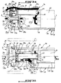
- Figure 3a is a schematic side elevational view in section of the front part of the carriage of Figure 1, along the line IIIa-IIIa of Figure 3b.
- Figure 3b is a schematic top view and partially in section of Figure 3a.
- Figure 4 is a schematic cross-sectional view, along the line IV-IV of Figure 3b, when the carriage is in the pipeline.
- Figure 5 is a schematic view in cross section of the main transmission cable connecting the carriage to the outside.
- Figure 6a is a schematic side elevational view in section of the rear part of the console of the carriage of Figure 1, along the line VIa-VIa of Figure 6b.
- Figure 6b is a schematic top view partially broken away from Figure 6a.
- Figure 7a is a schematic cross-sectional view along line VIIa-VIIa of Figure 6b.
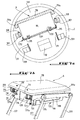
- FIG. 7b is a partial schematic perspective view of the exploration device in the deployed position of FIG. 1.
- FIGS. 8a and 8b are schematic views respectively in side elevation partially in section and from above of the front part of the console of FIG. 1.
- Figure 9 is a schematic cross-sectional view of another embodiment of the scanning device of the invention.
- Figure 10 is a functional block diagram of the apparatus of the invention.
- FIG. 1 represents a carriage 1 movable in translation in a partially torn pipe 2.
- the carriage 1 is connected via a main transmission cable 3 to an external command and control system 4 shown in FIG. 10.
- the carriage 1 consists of a main body 5 which extends in a longitudinal direction and of a cantilever console 6 rotatably mounted around a longitudinal axis 7 at the front of the main body 5.
- the main body 5 is supported by two pairs of wheels 8a and 8b arranged on either side of the longitudinal direction of the main body 5, the wheels of one of said pairs 8a being mutually driven by means of a belt endless 9.
- the cross section of the belt 9 can advantageously be trapezoidal.
- the main body 5 consists of two parts 5a and 5b adjustable relative to each other in the longitudinal direction 7 and connected by means of clamping screws 10.
- the rear part 5a of the main body 5 consists of a casing 11 which is extended forward by its lower end by a small flat plate 12 and of a housing 13 which extends in the longitudinal direction 7 along one of the sides of the carriage 1 which is opposite to the side of the belt 9.
- the front part 5b of the main body 5 consists of a frame 14 supported liftable on a large flat plate 15.
- a longitudinal blind recess 16 is formed in the underside of the large plate 15, said recess 16 being capable of receiving the end of a lug 17 housed in a hole in the plate 12 and which projects from its upper face.
- the recess 16 is arranged in a longitudinal direction and in the center of the large plate 15 to facilitate its centering with the small plate 12.
- oblong lights 18, four in number are provided at through the thickness of the large plate 15, opposite tapped holes 19 formed through the small plate 12.
- the head of the clamping screws 10 bears on a counterbore 20 formed around the oblong slots 18 on the upper face of the large plate 15, so that the two plates 12 and 15 can be clamped against each other by screwing the threaded rod of the clamping screws 10 in each tapped hole 19.
- the casing 11 consists of a frame 21 closed in leaktight manner by a cover 22.
- the upper and lower peripheral ends of the chassis 21 and of the cover 22 respectively have a flat marginal rim capable of tightening a peripheral seal 23.
- the cover 22 has at the rear a tab 24a which projects and which is intended to be hung on a rope forming a sling (not shown in the drawing) for lowering or mounting the carriage 1 in the pipe 2.
- a half of a ring 24a protrudes from the rear of the chassis 21 and can also be used to hang a rope for the descent or ascent of the carriage 1.
- An external waterproof socket 25 for receiving the main cable 3 is fixed to the rear of the chassis 21.
- the main cable 3 is connected to the entire wiring of the carriage 1.
- an electric motor 26 intended to control the locomotion of the carriage 1.
- the electric motor 26 has carbon-forming conductors 27 at its periphery and it is connected via a plate 28 to a reduction mechanism 29.
- the shaft 30 of the electric motor 26 is housed in a first pulley 31 which drives, via an endless belt 32, a second pulley 33 in which a shaft 34 is integrally housed.
- the shaft 34 rotates, by means of a set of reducing gears, not shown in the drawing, an axle 35a which connects the two rear wheels 8a and 8b of the carriage 1.
- Wheels of different diameters can be used, as shown in phantom in Figures 2b and 3b.
- a curved tab 36 fixed on the reduction mechanism 29 supports a potentiometer 37 capable of measuring the angular inclination relative to the vertical of a pendulum 38 forming a pendulum which includes a ballast 39 at its lower part.
- the pendulum 38 makes it possible to detect the transverse inclination of the carriage 1 inside the pipe to be explored.
- a plate 40 for varying the speed of the motors 26 and 58 of the carriage is housed at the rear of the casing 11, as shown in phantom in FIGS. 2a and 2b.
- Electronic components notably forming encoders 40a can be housed in the middle of the casing 11, as shown in dashed lines in FIG. 2a.
- the casing 11 has on the outside on one of its sides cooling fins 41a and 41b intended to dissipate the heat produced by the various electronic components.
- the cooling fins 41b are in thermal contact with a side plate 42 for protecting the carriage, shown in FIG. 1.
- FIG. 2a, 3a and 3b There is shown in Figures 2a, 3a and 3b a housing 43 for signal processing supported by the large plate 15 and having a coaxial cable 44 adapted to be housed in hooks 45 projecting from the outer side wall of the housing 11 .
- the electric motor 26 is controlled by the plate 40 by means of power transistors not shown in the drawings.
- the coaxial cable 44 drags behind the carriage 1 and is connected to an outdoor central unit 47.
- FIG. 2b shows without the transmitter 43 and without the cover 22.
- the electric motor 26 has a wire 48 connected on its side wall.
- FIG. 2b shows electronic components, in particular forming a digital / analog converter 49 shown in phantom, for controlling the plate 40.
- the casing 11 is extended laterally and forwards by the housing 13 which is constituted by the chassis 21 closed in leaktight manner by a large closing plate 50, by means of seals 51.
- the housing 13 comprises an upper compartment 13a in which is housed in particular a multiplexer 52 and a lower compartment not shown in the drawing crossed by a secondary transmission cable 3a which is connected to the main cable 3.
- a small closing plate 53 is tightly connected to the housing 13 by means of seals 54.
- the housing 13 comprises at the front a small compartment 13b in which is housed a disconnectable socket 55 used to connect the secondary cable 3a to cables 3b and 3c.
- the cable 3b is connected via a sealed cable gland 56 to the frame 14.
- the console 6 is rotatably mounted and cantilevered on the frame 14, by means of a hollow shaft 57, of axis coinciding with the longitudinal axis 7 of the carriage 1.
- the rotation of the console 6 is controlled by an electric geared motor 58 driving an output shaft 58a which rotates a large pinion 59a cooperating with a small pinion 59b secured to a shaft connected to a potentiometer 60.
- the geared motor 58 is housed in a rear cover 61 tightly connected to the rear face of the frame 14 by means of seals 62.
- the potentiometer 60 is connected to the cable 3b.
- the geared motor 58 has at the rear plugs 63 for electrical connection.
- a front cover 64 is fixed on the front face of the frame 14 and has inside a small pulley 65 driven in rotation by the output shaft 58a of the gear motor 58 and a large pulley 66 driven in rotation by a belt 67 which connects the two pulleys 65 and 66.
- the large pulley 66 is capable of rotating the hollow shaft 57 which is crossed by the cable 3c.
- the frame 14 comprises a first pair of bearings 68a disposed around the output shaft 58a of the geared motor 58 and a second pair of bearings 68b disposed around the hollow shaft 57.
- a hollow mechanical stop plate 69 is mounted on the rear face of the hollow shaft 57.
- FIG. 4 shows that the frame 14 consists of an upper block 14a fitted onto a lower block 14b, these two blocks being secured by means of clamping screws 70.
- the two blocks 14a and 14b are crossed in the direction of the height by two columns 71a and 71b, self-lubricating rings 72 ensuring the movement between the columns and the frame 14.
- the columns 71a and 71b are fixed by their lower ends in support flanges 15a at the front of the large plate 15 and the frame 14 can slide vertically on these columns.
- An adjustment screw 73 is mounted on the upper face of the block 14a and is screwed into a thread 74 formed coaxially in the column 71b.
- the head of the adjustment screw 73 can rotate on itself, but it is blocked vertically relative to the block 14a between an external circlip and a shoulder formed on said screw 73 (not shown in the drawing).
- the adjustment screw 73 makes it possible to vertically move the frame 14 relative to the large plate 15 and therefore to make a fine adjustment in the vertical position of the hollow shaft 57, by screwing and unscrewing the screw 73 inside the thread 74.
- a plate 75a supported by two thin rods and a gantry 75b are mounted on the upper face of the block 14a to guide a coaxial cable 44a connected to the processing unit 43.
- the front wheels 8a and 8b of the carriage 1 are mutually driven in rotation by means of an axle 35b.
- FIG. 5 shows the various constituent elements of the main transmission cable 3.
- the wall of the cable 3 consists of an outer polyurethane protective sheath 76, an intermediate layer of braided Kevlar fibers 77, a polyvinyl chloride (PVC) sheath 78 and an inner polyester tape 79.
- PVC polyvinyl chloride
- the main cable 3 contains a plurality of cables which all consist of a copper wire 80 surrounded by an insulating sheath 81 in PVC.
- three conductors 82a make it possible to establish a reference voltage in the carriage 1, commonly designated by voltage O volt.
- Two other conductors 82b make it possible to establish in the carriage a voltage of 30 volts relative to the reference voltage and supply energy to the electric motor 26 for driving the carriage in translation.
- a conductor 83 makes it possible to establish a voltage of 24 volts in the carriage and supplies energy to the geared motor 58 for rotational drive, the multiplexer 52, a selective displacement motor 84, projectors 85a and 85b and cameras 86a and 86b on the console 6.
- Two coaxial cables 87 are used to transmit the signals emitted by the cameras 86a and 86b.
- a cable 88 comprises an intermediate layer 88a of braided copper wires forming a shield, making it possible to establish a reference voltage in the multiplexer 52.
- the conductor 88 carries the signals between the multiplexer 52 and the external system 4.
- a cable 89 comprises an intermediate shield 89a and two internal conductors 89b which transmit to the external system 4 signals of position of the radar antenna 90 mounted on the console 6 and of transverse inclination of the carriage 1 relative to the vertical.
- the hollow plate 69 has protuberances forming mechanical stops 69a cooperating with the lower block 14b to limit the angular travel of the console 6 around the longitudinal axis 7 to about half a turn on either side of a central position of the console 6 in which the radar antenna 90 is directed towards the upper wall of the pipe 2.
- the information transmitted by the radar antenna 90 being very sensitive to parasites and other disturbances, it is currently necessary to use a very short coaxial cable 44a to minimize the pressure drops and to board the treatment unit 43 .
- the angular travel of the console 6 must therefore be limited to prevent the coaxial cable 44a connecting the radar antenna 90 at its processing unit 43 does not twist around the rotation shaft 57 and above all does not disconnect, during the rotation of the console 6, due to the short length of this coaxial cable 44a.
- the front end of the hollow shaft 57 is integral with the chassis 91 of the console 6.
- a roll bar 92 is fixed to the rear of the chassis 91 to serve as a guide means for the coaxial cable 44a connected to the radar antenna 90.
- the chassis 91 supports a casing 93 which has a cover 93a fixed in leaktight manner via the seals 94 an end flange of said casing 93.
- the selective displacement geared motor 84 which comprises a transmission shaft 84a connected to a reduction return unit 95 by means of a coupling sleeve 96.
- the geared motor 84 has electrical connection plugs 84b towards the front for its power supply from the cable 3c or from an emergency electric storage battery 84c, housed in the casing 93.
- the geared motor 84 is integrally connected to the reduction resumption housing 95 by means of a curved plate 97 which is held in position by through a lug 98 which projects from the internal surface of the cover 93a.
- the reduction return unit 95 is crossed by a reduction shaft 99 which has at one of its ends a lever 100 capable of turning integrally with the reduction shaft 99 between two angular abutment positions defined by microswitches 101, so as to limit the angular travel of the reduction shaft 99.
- FIG. 6a the lever 100 in a frontal plane, when in reality it is disposed on the other side of the reduction resumption box 95, as is clearly shown by Figure 6b.
- the other end of the reduction shaft 99 is integrally housed in a reduction pulley 102 which rotates a toothed pulley 103 by means of an endless belt 104.
- Each end of the shaft 105 is secured to an arm 107 capable of undergoing a circular movement, outside the side walls of the frame 91 and in a plane perpendicular to the shaft 105.
- the arms 107 are articulated at their other end on elongated metal strips 108.
- the elongated strips 108 have at their longitudinal ends a flange 110 which projects perpendicularly inward relative to the plane of each elongated strip 108. These flanges 110 are pierced with a guide hole in which a rod 111 can slide.
- Each rod 111 has at its lower end a support flange 111a capable of coming into abutment under the flanges 110.
- a plate 112 is elastically supported by helical springs 113 interposed between the flanges 110 and plates 114 secured to the plate 112, each rod 111 being secured by its upper end to a plate 114, and being able to slide axially in the helical springs 113.
- the plate 112 consists of two lateral branches 115 which are extended at their longitudinal ends by vertical tongues 116 integral with the plates 114, the two branches 115 being connected by crosspieces 117.
- a shoe 118 forming a mechanical protection element permeable to electromagnetic waves is fixed on the upper face of the plates 114 by means of screws 119.
- the shoe 118 rubs against the internal wall of the pipe 2 during its exploration by the radar antenna 90 and therefore protects the latter from any wear or deterioration.
- the radar antenna 90 forming a transceiver is housed between the plate 112 and the protective pad 118.
- Adjustable stops 120 are advantageously mounted on the plate 112 to allow optimal clamping of the antenna 90, also by means of screws 119.
- the shoe 118 has at its periphery bevelled walls 118a of a shape adapted to the inner circular wall of the pipe 2.
- the radar antenna 90 is shown in phantom in a deployed position.
- An elongated tube 121 is removably mounted by one of its ends at the front of the chassis 91.
- the elongated tube 121 is connected by its other end to a first camera 86a consisting of a tubular sleeve 122a and a porthole 123a.
- the camera 3D wiring 86a partially crosses the elongated tube 121 and is connected to a connector 124a mounted on the chassis 91.
- a second connector 124b mounted on the chassis 91 is connected to another 3d transmission cable which is connected to a second camera 86b and to the projectors 85a and 85b.
- the first camera 86a is rigidly linked to the elongated tube 121 and directed towards the front of the carriage, while the second camera 86b is directed towards the rear in the direction of the radar antenna 90.
- the camera 86b is pivotally mounted on the tube 121 around an axis 125b perpendicular to the longitudinal axis 7 of the carriage 1.
- the projectors 85b are arranged on each side of the camera 86b and directed towards the rear so as to illuminate the radar antenna 90.
- the projector 85a is pivotally mounted around an axis 125a parallel to the axis 125b on the front end of the camera 86b so as to illuminate the pipe 2 towards the front.
- FIGS. 8a and 8b show a 3rd wire connecting the projectors 85a and 85b to each other.
- the angular inclination of the camera 86b and the projectors 85b is determined so that the radar antenna 90 always remains in their field of vision (shown by oblique lines in FIGS. 8a and 8b) during its use.
- the cameras 86a and 86b can advantageously include a wide-angle or panoramic lens called "fish-eye”.
- FIG. 9 represents another embodiment of the apparatus of the invention, in which the radar antenna 90 is replaced by a vibrating member 90 'forming a hammer and an accelerometer 126 which are mounted on the plate 112 by the 'via a fixing flange 127.
- the vibrating member 90 ′ comprises a counterweight consisting of a force sensor 128 and a protective head 129 and a guide rod 130 fixed by its upper end to the force sensor 128 and capable of sliding axially inside of a ring 131.
- the ring 131 is integrally housed in a support sleeve 131a which supports a coil 132 surrounding the vibrating member 90 '.
- the force sensor 128 is resiliently supported by the ring 131 by means of a helical spring 133 axially traversed by the guide rod 130.
- the accelerometer 126 is housed in a decoupling chamber 134 rigidly connected to a tube 135.
- a transmission cable 44a ' is connected to the accelerometer 126 and to the vibratory member 90'.
- the cable 44a comprises a connection cable 126a with the accelerometer 126, supply wires not shown from the coil 132 and a connection cable 128a with the force sensor 128.
- the vibratory member 90 ′ and the accelerometer 126 make it possible to measure the thickness of the coatings and / or the structure of the pipes, to detect the presence of cracks or cavities in the walls of the pipes to be inspected and to assess the quality of the soil / structure interface.
- the counterweight leaves its housing to vibrate against the wall of the pipe to be inspected.
- the vibrations are transformed into an electrical signal by the force sensor 128 and this signal is sent, via the cable 44'a, or signal processing box 43 housed on the carriage.
- the plate 112 is not equipped with the shoe 118.
- the drum 136 comprises a tachometer device intended to measure the distance traveled by the carriage 1 during its progression in the pipeline (not shown in the drawings).
- the storage drum 136 is connected by means of a cable 137 to the command and control system 4.
- This command and control system 4 comprises two television screens 138 for displaying the video information transmitted by the cameras 86a and 86b on board the carriage 1.
- the screen 138 which is associated with the camera 86a makes it possible to control the progress of the carriage 1 and to detect any obstructions or collapses of the inspected pipe 2.
- the screen 138 which is associated with the camera 86b makes it possible to control the position of the exploration device 90, 90 ′ during its selective movement between its retracted position and its deployed position and above all to ensure that the exploration device 90 , 90 ′ remains in contact with the internal wall of the pipe 2 during its exploration.
- the thickness of the air layer 139 separating the upper face of the pad 118 from the internal wall of pipe 2 remains constant so as not to distort the information transmitted by the radar antenna 90 (see FIG. 7a).
- the thickness of the air layer 139 varies and this variation is detected by the camera 86b which displays the displacement of the rods 111 forming sensors connected to the shoe 118.
- the camera 86b is tilted in a position such that it can view at least two of the four sliding rods forming sensors 111, when the exploration device 90, 90 ′ is in its deployed position.
- the screens 138 are connected to a video recording device not shown in the drawing.
- the command and control system 4 comprises a main device 140 connected on the one hand to the screens 138 by video cables 138a and on the other hand to the cable 137.
- the apparatus 140 has on its front face a command and control panel 140a.
- the apparatus 140 is in the form of a drawer, commonly known as a "rack", intended to be housed in a cabinet forming a bay, by means of handles 140b arranged on the table 140a.
- the central unit 47 of the exploration device 90, 90 ′ may comprise a cathode oscilloscope and a recorder on magnetic tape of the information transmitted (not shown in the drawing).
- the console 6 can advantageously be provided with a bumper cap to protect the device exploration 90, 90 'during the descent of the carriage in a pipe.
- the entire carriage 1 is fluid-tight, as evidenced by the various seals mounted on the latter, and it is particularly resistant to corrosive agents likely to be encountered in the pipeline and to cleaning products of the carriage, such as the karcher. .
Landscapes
- Engineering & Computer Science (AREA)
- General Engineering & Computer Science (AREA)
- Chemical & Material Sciences (AREA)
- Combustion & Propulsion (AREA)
- Mechanical Engineering (AREA)
- Investigating Materials By The Use Of Optical Means Adapted For Particular Applications (AREA)
- Geophysics And Detection Of Objects (AREA)
Abstract
Description
La présente invention concerne un appareil d'inspection de l'état physique de canalisations non accessibles ou visitables par l'homme, notamment de réseaux d'assainissement urbains.The present invention relates to an apparatus for inspecting the physical state of pipes which are not accessible or which can be visited by humans, in particular of urban sanitation networks.
Dans ces réseaux, il est indispensable de surveiller l'état physique des canalisations, notamment des collecteurs, afin de prévenir toute défaillance du réseau et d'effectuer les travaux d'entretien et de restauration nécessaires.In these networks, it is essential to monitor the physical condition of the pipes, especially the collectors, in order to prevent any network failure and to carry out the necessary maintenance and restoration work.
Parmi les défaillances généralement rencontrées dans les réseaux d'assainissement, on peut citer notamment l'obstruction des canalisations, la fuite d'effluents circulant dans les canalisations vers l'extérieur ou l'infiltration de matière extérieure dans les canalisations suite à une fissuration de ces dernières, et une déformation ou une rupture mécanique des canalisations.Among the failures generally encountered in sewerage networks, one can cite in particular the obstruction of the pipes, the leakage of effluents circulating in the pipes towards the outside or the infiltration of external matter in the pipes following a cracking of the latter, and mechanical deformation or rupture of the pipes.
Dans les réseaux d'assainissement, on distingue généralement deux catégories de canalisations.In sewerage networks, there are generally two categories of pipes.
Une première catégorie de canalisations est directement accessible et visitable par l'homme, ce qui permet à un opérateur humain d'inspecter visuellement l'état général de ces dernières et de manipuler des outils adaptés pour obtenir des informations spécifiques concernant la structure et l'environnement géotechnique de ces canalisations.A first category of pipes is directly accessible and can be visited by humans, which allows a human operator to visually inspect the general condition of the latter and to use suitable tools to obtain specific information concerning the structure and the geotechnical environment of these pipes.
L'obtention de ces informations est nécessaire pour l'établissement d'un diagnostic fiable de l'état physique des canalisations et constitue une condition préalable à tous travaux de restauration ou d'entretien.Obtaining this information is necessary for establishing a reliable diagnosis of the physical condition of the pipes and is a prerequisite for any restoration or maintenance work.
La seconde catégorie de canalisations n'est pas directement accessible ou visitable par l'homme.The second category of pipes is not directly accessible or manageable.
Il est connu d'inspecter cette seconde catégorie de canalisations au moyen de chariots mobiles en translation, télécommandés de l'extérieur, notamment par l'intermédiaire de câbles de transmission et qui comportent au moins une caméra et un projecteur dirigés vers l'avant du chariot pour visualiser des obstacles à sa progression et l'état de la canalisation à inspecter, et un ensemble moteur pour entraîner notamment ledit chariot en translation.It is known to inspect this second category of pipes by means of mobile trolleys in translation, remotely controlled from the outside, in particular by means of transmission cables and which comprise at least one camera and one projector directed towards the front of the carriage for viewing obstacles to its progress and the state of the pipe to be inspected, and an engine assembly for driving said carriage in particular in translation.
Les chariots décrits ci-dessus nécessitent une miniaturisation des outils habituellement manipulés par un opérateur humain, du fait que les canalisations à inspecter présentent un diamètre interne réduit, généralement compris entre 200 et 600 mm.The trolleys described above require miniaturization of the tools usually handled by a human operator, because the pipes to be inspected have a reduced internal diameter, generally between 200 and 600 mm.
Actuellement, les chariots destinés à inspecter cette catégorie de canalisations ne disposent que de caméras de dimensions réduites, telles que des "caméra-stylos".Currently, the trolleys intended to inspect this category of pipes have only cameras of reduced dimensions, such as "camera-pens".
Cependant, l'inspection télévisuelle ne permet pas d'obtenir toutes les informations nécessaires à l'établissement d'un diagnostic fiable, telles que par exemple les caractéristiques géométriques et mécaniques des canalisations, les caractéristiques de l'interface entre le sol et les canalisations, la localisation et la quantification des défaillances dans la canalisation et/ou dans son environnement.However, the television inspection does not provide all the information necessary for establishing a reliable diagnosis, such as for example the geometric and mechanical characteristics of the pipes, the characteristics of the interface between the ground and the pipes. , localization and quantification of failures in the pipeline and / or its environment.
L'inspection de la seconde catégorie de canalisations est rendue encore plus difficile par le fait que des effluents agressifs et corrosifs circulent généralement dans les canalisations, que le milieu régnant à l'intérieur de ces dernières est humide, et que les canalisations sont généralement fabriquées en béton, en grès, en amiante-ciment ou en béton armé.Inspection of the second category of pipes is made even more difficult by the fact that aggressive and corrosive effluents generally circulate in pipes, that the environment inside them is humid, and that pipes are generally made of concrete, sandstone, asbestos-cement or reinforced concrete.
Bien que l'invention est décrite en liaison avec l'inspection de réseaux d'assainissement, il est bien évident qu'elle n'y est nullement limitée et qu'elle peut s'appliquer à tout type de canalisations qui n'est pas directement accessible ou visitable par l'homme et qui nécessite une inspection précise de son état physique.Although the invention is described in connection with the inspection of sewerage networks, it is obvious that it is in no way limited to it and that it can be applied to any type of pipe which is not directly accessible or visitable by man and which requires a precise inspection of his physical state.
La présente invention a pour but d'éliminer les inconvénients précités et de proposer un appareil d'inspection de l'état physique des canalisations permettant d'obtenir suffisamment d'informations à son sujet pour établir un diagnostic fiable de celui-ci.The object of the present invention is to eliminate the aforementioned drawbacks and to propose an apparatus for inspecting the physical state of the pipes making it possible to obtain sufficient information about it in order to establish a reliable diagnosis of it.
La présente invention a pour objet un appareil d'inspection de l'état physique de canalisations non accessibles ou visitables par l'homme, notamment de réseaux d'assainissement, constitué d'un chariot mobile en translation dans une canalisation à inspecter, télécommandé de l'extérieur, notamment par l'intermédiaire de câbles de transmission, et qui comporte au moins une caméra et un projecteur dirigés vers l'avant du chariot pour visualiser les obstacles à sa progression et l'état général du collecteur, et un ensemble moteur pour entraîner notamment ledit chariot en translation, caractérisé en ce qu'une console, notamment en porte-à-faux, est montée rotative autour d'un axe longitudinal à l'avant du chariot et supporte un dispositif d'exploration sélectivement mobile entre une position rétractée sur ladite console et une position déployée de contact avec la paroi interne de la canalisation à inspecter, ladite console étant pourvue d'un moyen de détection pour détecter la position relative actuelle du dispositif d'exploration, notamment lorsqu'il est dans sa position déployée, et en ce que l'appareil d'inspection comporte un système extérieur de commande et de contrôle du chariot et une unité centale de traitement des informations transmises par le dispositif d'exploration.The subject of the present invention is an apparatus for inspecting the physical state of pipes which are not accessible or which can be visited by humans, in particular sanitation networks, consisting of a carriage movable in translation in a pipe to be inspected, remotely controlled by the exterior, in particular by means of transmission cables, and which comprises at least one camera and one projector directed towards the front of the carriage to visualize the obstacles to its progress and the general condition of the collector, and a motor assembly to drive said carriage in particular in translation, characterized in that a console, in particular cantilever, is rotatably mounted about a longitudinal axis at the front of the carriage and supports a device for selectively mobile exploration between a retracted position on said console and a deployed position of contact with the internal wall of the pipe to be inspected, said console being provided with detection means for detecting the current relative position of the exploration device, in particular when it is in its deployed position, and in that the inspection apparatus includes a system external command and control of the trolley and a central unit for processing the information transmitted by the exploration device.
Selon un premier mode de réalisation particulier de l'invention, le dispositif d'exploration est constitué avantageusement d'une antenne de radar de dimensions réduites amoviblement couverte par un élément de protection mécanique perméable aux ondes électromagnétiques du côté de la paroi interne de la canalisation à inspecter.According to a first particular embodiment of the invention, the exploration device advantageously consists of a radar antenna of reduced dimensions removably covered by a mechanical protection element permeable to electromagnetic waves on the side of the internal wall of the pipe. to inspect.
L'antenne de radar permet notamment de détecter la présence d'armatures métalliques, de vides ou de fissures dans la paroi de la canalisation et de déterminer les caractéristiques de l'interface sol/canalisation et du sol.The radar antenna makes it possible in particular to detect the presence of metal reinforcements, voids or cracks in the wall of the pipe and to determine the characteristics of the ground / pipe interface and of the ground.
Selon un deuxième mode de réalisation particulier de l'invention, le dispositif d'exploration est constitué d'un organe vibratoire, tel qu'un marteau et d'un accéléromètre, ledit organe vibratoire comportant une masselotte apte à venir frapper la paroi interne de la canalisation lorsque le dispositif d'exploration est dans sa position déployée.According to a second particular embodiment of the invention, the exploration device consists of a vibrating member, such as a hammer and an accelerometer, said vibrating member comprising a counterweight capable of striking the internal wall of the pipe when the exploration device is in its deployed position.
Selon une caractéristique particulière de l'invention, le moyen de détection précité est constitué d'au moins une deuxième caméra et un deuxième projecteur dirigés vers le dispositif d'exploration de manière à pouvoir le visualiser sur au moins une portion de sa course incluant sa position déployée.According to a particular characteristic of the invention, the aforementioned detection means consists of at least a second camera and a second projector directed towards the exploration device so as to be able to visualize it over at least a portion of its travel including its deployed position.
L'appareil d'inspection selon l'invention est avantageusement caractérisé par un moyen de déplacement sélectif du dispositif d'exploration, constitué de bras agencés en parallélogrammes articulés autour d'axes perpendiculaires audit axe longitudinal, pour rétracter et déployer le dispositif d'exploration.The inspection apparatus according to the invention is advantageously characterized by a means of selective displacement of the exploration device, consisting of arms arranged in parallelograms articulated around axes perpendicular to said longitudinal axis, for retracting and deploying the exploration device .
Selon une autre caractéristique de l'invention, le dispositif d'exploration est logé sur un plateau qui est supporté élastiquement par exemple au moyen de ressorts hélicoïdaux, par ledit moyen de déplacement sélectif.According to another characteristic of the invention, the exploration device is housed on a plate which is resiliently supported, for example by means of helical springs, by said means of selective displacement.
Ce plateau peut comporter des tiges formant capteurs qui font saillie de sa face inférieure, de sorte que leur déplacement soit détecté au moins partiellement par ledit moyen de détection.This plate may include rods forming sensors which project from its underside, so that their movement is detected at least partially by said detection means.
Selon encore une autre caractéristique de l'invention, le chariot comprend un système à pendule formant balancier permettant de mesurer l'inclinaison transversale du chariot par rapport à la verticale pendant son déplacement.According to yet another characteristic of the invention, the carriage comprises a pendulum system forming a pendulum making it possible to measure the transverse inclination of the carriage relative to the vertical during its movement.
L'ensemble moteur précité comprend avantageusement trois moteurs électriques pour commander respectivement la locomotion du chariot, la rotation de la console et le déplacement sélectif du dispositif d'exploration.The aforementioned motor assembly advantageously comprises three electric motors for respectively controlling the locomotion of the carriage, the rotation of the console and the selective movement of the exploration device.
Dans un mode particulièrement avantageux de l'invention, la console est munie d'une batterie d'accumulateur électrique indépendante pour alimenter le moteur électrique de commande en rétractation automatique du moyen de déplacement sélectif notamment lors d'une rupture accidentelle de l'alimentation générale en énergie du chariot.In a particularly advantageous embodiment of the invention, the console is provided with an independent electric accumulator battery for supplying the electric control motor with retraction automatic of the selective displacement means in particular during an accidental rupture of the general energy supply of the carriage.
Le corps principal du chariot est avantageusement constitué de deux parties pouvant coulisser l'une par rapport à l'autre dans la direction longitudinale du chariot, ce qui permet de faire varier l'empattement du chariot.The main body of the carriage advantageously consists of two parts which can slide relative to one another in the longitudinal direction of the carriage, which makes it possible to vary the wheelbase of the carriage.
Dans le cas où le roulement du chariot est assuré par deux paires de roues entraînées par l'intermédiaire d'une courroie sans fin, il est possible de mettre en tension cette courroie en écartant lesdites parties du châssis l'une par rapport à l'autre.In the case where the rolling of the carriage is ensured by two pairs of wheels driven by means of an endless belt, it is possible to tension this belt by spreading said parts of the chassis one relative to the other.
Le chariot peut comporter des butées de fin de course pour limiter la rotation de la console à environ un demi-tour de part et d'autre d'une position initiale prédéterminée de ladite console.The carriage may include end-of-travel stops to limit the rotation of the console to around half a turn on either side of a predetermined initial position of said console.
L'appareil selon l'invention comporte avantageusement des moyens de réglage de la position verticale de l'arbre de rotation de la console par rapport au corps principal du chariot.The apparatus according to the invention advantageously includes means for adjusting the vertical position of the console's rotation shaft relative to the main body of the carriage.
Le réglage principal de la position verticale de l'axe de rotation de la console est effectué avantageusement en faisant varier le diamètre des roues du chariot, alors que le moyen de réglage précité constitue plutôt un réglage fin de ladite position verticale.The main adjustment of the vertical position of the axis of rotation of the console is advantageously carried out by varying the diameter of the wheels of the carriage, while the aforementioned adjustment means rather constitutes a fine adjustment of said vertical position.
Selon une autre caractéristique de l'invention, la caméra qui est dirigée vers l'avant du chariot, est avantageusement coaxiale avec ledit axe longitudinal de rotation de la console, ce qui permet d'obtenir sur l'écran d'affichage extérieur une représentation linéaire de la progression du chariot dans la canalisation.According to another characteristic of the invention, the camera which is directed towards the front of the carriage, is advantageously coaxial with said longitudinal axis of rotation of the console, which makes it possible to obtain on the external display screen a linear representation of the progress of the carriage in the pipeline.
Dans une variante de réalisation de l'invention, l'appareil peut comporter en outre des sondes de diagraphie nucléaire embarquées sur le chariot pour détecter des variations de densité et d'humidité de matériaux extérieurs à la canalisation, notamment pour détecter des fuites d'effluents vers l'extérieur des canalisations.In an alternative embodiment of the invention, the device can also include nuclear logging probes on board the trolley to detect variations in density and humidity of materials outside the pipeline, in particular to detect leaks from effluent to the outside of the pipes.
L'appareil selon l'invention comporte avantageusement au moins un tambour de stockage extérieur à la canalisation à inspecter autour duquel vient s'enrouler le câble de transmission du chariot et/ou du dispositif d'exploration, un dispositif compte-tours étant monté sur au moins un tambour pour mesurer la distance parcourue par le chariot lors de sa progression dans la canalisation à inspecter et permettre de localiser les défaillances éventuelles de celle-ci.The device according to the invention advantageously comprises at least one storage drum outside the pipe to be inspected around which the transmission cable of the carriage and / or of the exploration device is wound, a tachometer device being mounted on at least one drum for measuring the distance traveled by the carriage during its progression in the pipe to be inspected and making it possible to locate any failures thereof.
L'invention sera mieux comprise et d'autres buts, caractéristiques et avantages de celle-ci apparaîtront plus clairement au cours de la description explicative suivante, donnée uniquement à titre d'exemples purement illustratifs et non limitatifs de plusieurs modes de réalisation particuliers actuellement préférés de l'invention, représentés sur les dessins annexés dans lesquels.The invention will be better understood and other aims, characteristics and advantages thereof will appear more clearly during the following explanatory description, given solely by way of purely illustrative and nonlimiting examples of several particular embodiments currently preferred. of the invention, shown in the accompanying drawings in which.
La figure 1 est une vue schématique en perspective du chariot selon un premier mode de réalisation de l'invention, lorsque ce dernier est dans une canalisation.Figure 1 is a schematic perspective view of the carriage according to a first embodiment of the invention, when the latter is in a pipeline.
La figure 2a est une vue schématique en élévation latérale et en coupe de la partie postérieure du chariot de la figure 1, suivant la ligne IIa-IIa de la figure 2b.Figure 2a is a schematic side elevational view in section of the rear part of the carriage of Figure 1, along the line IIa-IIa of Figure 2b.
La figure 2b est une vue schématique de dessus de la figure 2a.Figure 2b is a schematic top view of Figure 2a.
La figure 3a est une vue schématique en élévation latérale et en coupe de la partie antérieure du chariot de la figure 1, suivant la ligne IIIa-IIIa de la figure 3b.Figure 3a is a schematic side elevational view in section of the front part of the carriage of Figure 1, along the line IIIa-IIIa of Figure 3b.
La figure 3b est une vue schématique du dessus et partiellement en coupe de la figure 3a.Figure 3b is a schematic top view and partially in section of Figure 3a.
La figure 4 est une vue schématique en section transversale, suivant la ligne IV-IV de la figure 3b, lorsque le chariot est dans la canalisation.Figure 4 is a schematic cross-sectional view, along the line IV-IV of Figure 3b, when the carriage is in the pipeline.
La figure 5 est une vue schématique et en coupe transversale du câble de transmission principal reliant le chariot à l'extérieur.Figure 5 is a schematic view in cross section of the main transmission cable connecting the carriage to the outside.
La figure 6a est une vue schématique en élévation latérale et en coupe de la partie arrière de la console du chariot de la figure 1, suivant la ligne VIa-VIa de la figure 6b.Figure 6a is a schematic side elevational view in section of the rear part of the console of the carriage of Figure 1, along the line VIa-VIa of Figure 6b.
La figure 6b est une vue schématique de dessus partiellement arrachée de la figure 6a.Figure 6b is a schematic top view partially broken away from Figure 6a.
La figure 7a est une vue schématique en section transversale suivant la ligne VIIa-VIIa de la figure 6b.Figure 7a is a schematic cross-sectional view along line VIIa-VIIa of Figure 6b.
La figure 7b est une vue schématique partielle en perspective du dispositif d'exploration en position déployée de la figure 1.FIG. 7b is a partial schematic perspective view of the exploration device in the deployed position of FIG. 1.
Les figures 8a et 8b sont des vues schématiques respectivement en élévation latérale partiellement en coupe et de dessus de la partie avant de la console de la figure 1.FIGS. 8a and 8b are schematic views respectively in side elevation partially in section and from above of the front part of the console of FIG. 1.
La figure 9 est une vue schématique en section transversale d'un autre mode de réalisation du dispositif d'exploration de l'invention.Figure 9 is a schematic cross-sectional view of another embodiment of the scanning device of the invention.
La figure 10 est un schéma synoptique fonctionnel de l'appareil de l'invention.Figure 10 is a functional block diagram of the apparatus of the invention.
On a représenté sur les différentes figures du dessin uniquement les parties essentielles à la compréhension de l'appareil.The various figures in the drawing show only the parts essential for understanding the device.
La figure 1 représente un chariot 1 mobile en translation dans une canalisation partiellement arrachée 2.FIG. 1 represents a carriage 1 movable in translation in a partially
Le chariot 1 est relié par l'intermédiaire d'un câble de transmission principal 3 à un système extérieur de commande et contrôle 4 représenté sur la figure 10.The carriage 1 is connected via a
Le chariot 1 est constitué d'un corps principal 5 qui s'étend dans une direction longitudinale et d'une console en porte-à-faux 6 montée rotative autour d'un axe longitudinal 7 à l'avant du corps principal 5.The carriage 1 consists of a
On va maintenant décrire en détail le corps principal 5 du chariot 1 en référence aux figures 1 à 4.We will now describe in detail the
Le corps principal 5 est supporté par deux paires de roues 8a et 8b disposées de part et d'autre de la direction longitudinale du corps principal 5, les roues de l'une desdites paires 8a étant mutuellement entraînées par l'intermédiaire d'une courroie sans fin 9. La section transversale de la courroie 9 peut être avantageusement trapézoïdale.The
Le corps principal 5 est constitué de deux parties 5a et 5b réglables l'une par rapport à l'autre dans la direction longitudinale 7 et reliées par l'intermédiaire de vis de serrage 10.The
La partie postérieure 5a du corps principal 5 est constituée d'un carter 11 qui se prolonge vers l'avant par son extrémité inférieure par une petite plaque plane 12 et d'un boîtier 13 qui s'étend dans la direction longitudinale 7 le long d'un des côtés du chariot 1 qui est opposé au côté de la courroie 9.The
La partie antérieure 5b du corps principal 5 est constituée d'un bâti 14 supporté levable sur une grande plaque plane 15.The
Un évidement borgne longitudinal 16 est ménagé dans la face inférieure de la grande plaque 15, ledit évidement 16 étant apte à recevoir l'extrémité d'un ergot 17 logé dans un trou de la plaque 12 et qui fait saillie de sa face supérieure.A longitudinal
L'évidement 16 est disposé dans une direction longitudinale et au centre de la grande plaque 15 pour faciliter son centrage avec la petite plaque 12.The
On voit sur les figures 2a et 2b que des lumières oblongues 18, au nombre de quatre, sont ménagées à travers l'épaisseur de la grande plaque 15, en regard de trous taraudés 19 ménagés à travers la petite plaque 12.It can be seen in FIGS. 2a and 2b that
La tête des vis de serrage 10 prend appui sur un lamage 20 ménagé autour des lumières oblongues 18 sur la face supérieure de la grande plaque 15, de manière à pouvoir serrer les deux plaques 12 et 15 l'une contre l'autre par vissage de la tige filetée des vis de serrage 10 dans chaque trou taraudé 19.The head of the clamping screws 10 bears on a
Il est donc possible de régler la position relative des deux plaques 12 et 15 dans la direction longitudinale en faisant coulisser les vis de serrage 10 dans les lumières 18.It is therefore possible to adjust the relative position of the two
Il est possible de mettre en tension la courroie 9 en écartant lesdites parties 5a et 5b l'une par rapport à l'autre, étant donné que la paire de roues 8a comporte une roue montée sur chacune desdites parties 5a et 5b.It is possible to tension the
Le carter 11 est constitué d'un châssis 21 fermé de manière étanche par un couvercle 22.The
Les extrémités périphériques supérieure et inférieure respectivement du châssis 21 et du couvercle 22 comportent un rebord marginal plan apte à venir serrer un joint d'étanchéité périphérique 23.The upper and lower peripheral ends of the
Le couvercle 22 comporte à l'arrière une patte 24a qui fait saillie et qui est destinée à être accrochée à un cordage formant élingue (non représentée sur le dessin) pour descendre ou monter le chariot 1 dans la canalisation 2.The
Une moitié d'anneau 24a fait saillie à l'arrière du châssis 21 et peut également servir à l'accrochage d'un cordage pour la descente ou la montée du chariot 1.A half of a
Une prise étanche externe 25 de réception du câble principal 3 est fixée à l'arrière du châssis 21.An external
Le câble principal 3 est connecté à l'ensemble de la filerie du chariot 1.The
A l'intérieur du carter 11 est monté un moteur électrique 26 destiné à commander la locomotion du chariot 1.Inside the
Le moteur électrique 26 présente à sa périphérie des conducteurs formant charbon 27 et il est relié par l'intermédiaire d'une platine 28 à un mécanisme de réduction 29.The
L'arbre 30 du moteur électrique 26 est logé dans une première poulie 31 qui entraîne par l'intermédiaire d'une courroie sans fin 32 une deuxième poulie 33 dans laquelle est solidairement logé un arbre 34.The
L'arbre 34 entraîne en rotation, par l'intermédiaire d'un ensemble d'engrenages réducteurs, non représentés sur le dessin, un essieu 35a qui relie les deux roues arrière 8a et 8b du chariot 1.The
Il est possible d'utiliser des roues de différents diamètres, comme représentées en traits mixtes sur les figures 2b et 3b.Wheels of different diameters can be used, as shown in phantom in Figures 2b and 3b.
Une patte courbée 36 fixée sur le mécanisme de réduction 29 supporte un potentiomètre 37 apte à mesurer l'inclinaison angulaire par rapport à la verticale d'un pendule 38 formant balancier qui comporte un lest 39 à sa partie inférieure.A
Le pendule 38 permet de détecter l'inclinaison transversale du chariot 1 à l'intérieur de la canalisation à explorer.The
Une platine 40 de variation de vitesse des moteurs 26 et 58 du chariot est logée à l'arrière du carter 11, comme représentée en traits mixtes sur les figures 2a et 2b.A
Des composants électroniques formant notamment codeurs 40a peuvent être logés au milieu du carter 11, comme représentés en traits mixtes sur la figure 2a.Electronic components notably forming
Le carter 11 présente à l'extérieur sur l'un de ses côtés des ailettes 41a et 41b de refroidissement destinées à dissiper la chaleur produite par les différents composants électroniques. Les ailettes de refroidissement 41b sont en contact thermique avec une plaque latérale 42 de protection du chariot, représentée sur la figure 1.The
On a représenté sur les figures 2a, 3a et 3b un boîtier 43 de traitement du signal supporté par la grande plaque 15 et comportant un câble coaxial 44 apte à venir se loger dans des crochets 45 ménagés en saillie de la paroi latérale extérieure du carter 11.There is shown in Figures 2a, 3a and 3b a
On a représenté un transistor 46 entre les ailettes de refroidissement 41a.There is shown a
Le moteur électrique 26 est commandé par la platine 40 par l'intermédiaire de transistors de puissance non représentés sur les dessins.The
A l'instar du câble principal 3, le câble coaxial 44 traîne à l'arrière du chariot 1 et est connecté à une unité centrale extérieure 47.Like the
On a représenté la figure 2b sans le transmetteur 43 et sans le couvercle 22.FIG. 2b shows without the
Le moteur électrique 26 comporte un fil 48 connecté sur sa paroi latérale.The
On voit sur la figure 2b des composants électroniques formant notamment convertisseur numérique/analogique 49 représentés en traits mixtes, pour la commande de la platine 40.FIG. 2b shows electronic components, in particular forming a digital / analog converter 49 shown in phantom, for controlling the
Le carter 11 se prolonge latéralement et vers l'avant par le boîtier 13 qui est constitué par le châssis 21 fermé de manière étanche par une grande plaque de fermeture 50, par l'intermédiaire de joints d'étanchéité 51.The
Le boîtier 13 comporte un compartiment supérieur 13a dans lequel est logé notamment un multiplexeur 52 et un compartiment inférieur non représenté sur le dessin traversé par un câble secondaire de transmission 3a qui est relié au câble principal 3.The
Une petite plaque de fermeture 53 est reliée de manière étanche au boîtier 13 par l'intermédiaire de joints d'étanchéité 54.A
Le boîtier 13 comporte à l'avant un petit compartiment 13b dans lequel est logé une prise déconnectable 55 servant à connecter le câble secondaire 3a à des câbles 3b et 3c.The
Le câble 3b est connecté par l'intermédiaire d'un presse-étoupe étanche 56 au bâti 14.The
La console 6 est montée rotative et en porte-à-faux sur le bâti 14, par l'intermédiaire d'un arbre creux 57, d'axe confondu avec l'axe longitudinal 7 du chariot 1.The
La rotation de la console 6 est commandée par un motoréducteur électrique 58 entraînant un arbre de sortie 58a qui entraîne en rotation un grand pignon 59a coopérant avec un petit pignon 59b solidaire d'un arbre relié à un potentiomètre 60. Le motoréducteur 58 est logé dans un capot arrière 61 relié de manière étanche à la face postérieure du bâti 14 par l'intermédiaire de joints d'étanchéité 62.The rotation of the
Le potentiomètre 60 est connecté au câble 3b.The
Le motoréducteur 58 comporte à l'arrière des fiches 63 de connexion électrique.The geared
Un capot avant 64 est fixé sur la face antérieure du bâti 14 et comporte à l'intérieur une petite poulie 65 entraînée en rotation par l'arbre de sortie 58a du motoréducteur 58 et une grande poulie 66 entraînée en rotation par une courroie 67 qui relie les deux poulies 65 et 66.A
La grande poulie 66 est apte à entraîner en rotation l'arbre creux 57 qui est traversé par le câble 3c.The large pulley 66 is capable of rotating the
Le bâti 14 comporte une première paire de roulements 68a disposée autour de l'arbre de sortie 58a du motoréducteur 58 et une deuxième paire de roulements 68b disposée autour de l'arbre creux 57.The
Un plateau de butée mécanique creux 69 est monté sur la face postérieure de l'arbre creux 57.A hollow
La figure 4 montre que le bâti 14 est constitué d'un bloc supérieur 14a emmanché sur un bloc inférieur 14b, ces deux blocs étant solidarisés par l'intermédiaire de vis de serrage 70.FIG. 4 shows that the
Les deux blocs 14a et 14b sont traversés dans le sens de la hauteur par deux colonnes 71a et 71b, des bagues autolubrifiantes 72 assurant le déplacement entre les colonnes et le bâti 14.The two
Les colonnes 71a et 71b sont fixées par leur extrémité inférieure dans des brides de support 15a à l'avant de la grande plaque 15 et le bâti 14 peut coulisser verticalement sur ces colonnes.The
Une vis de réglage 73 est montée sur la face supérieure du bloc 14a et vient se visser dans un taraudage 74 ménagé coaxialement dans la colonne 71b.An
La tête de la vis de réglage 73 peut tourner sur elle-même, mais elle est bloquée verticalement par rapport au bloc 14a entre un circlips extérieur et un épaulement ménagé sur ladite vis 73 (non représentés sur le dessin).The head of the
La vis de réglage 73 permet de déplacer verticalement le bâti 14 par rapport à la grande plaque 15 et donc d'effectuer un réglage fin en position verticale de l'arbre creux 57, en vissant et dévissant la vis 73 à l'intérieur du taraudage 74.The
Une plaquette 75a supportée par deux tiges minces et un portique 75b sont montés sur la face supérieure du bloc 14a pour guider un câble coaxial 44a connecté au boîtier de traitement 43.A
Les roues avant 8a et 8b du chariot 1 sont mutuellement entraînées en rotation par l'intermédiaire d'un essieu 35b.The
On voit sur la figure 5 les différents éléments constitutifs du câble de transmission principal 3.FIG. 5 shows the various constituent elements of the
La paroi du câble 3 est constituée d'une gaine extérieure de protection en polyuréthane 76, d'une couche intermédiaire de fibres de Kevlar tressées 77, d'une gaine en polychlorure de vinyle (PVC) 78 et d'un ruban intérieur en polyester 79.The wall of the
Le câble principal 3 contient une pluralité de câbles qui sont tous constitués d'un fil en cuivre 80 entouré d'une gaine isolante 81 en PVC.The
Parmi ces différents câbles, trois conducteurs 82a permettent d'établir une tension de référence dans le chariot 1, communément désignée par tension O volt.Among these various cables, three
Deux autres conducteurs 82b permettent d'établir dans le chariot une tension de 30 volts par rapport à la tension de référence et alimentent en énergie le moteur électrique 26 d'entraînement en translation du chariot.Two
Un conducteur 83 permet d'établir une tension de 24 volts dans le chariot et alimente en énergie le motoréducteur 58 d'entraînement en rotation, le multiplexeur 52, un moteur de déplacement sélectif 84, des projecteurs 85a et 85b et des caméras 86a et 86b sur la console 6.A
Deux câbles coaxiaux 87 servent à transmettre les signaux émis par les caméras 86a et 86b.Two
Un câble 88 comporte une couche intermédiaire 88a en fils de cuivre tressés formant blindage, permettant d'établir une tension de référence dans le multiplexeur 52. Le conducteur 88 véhicule les signaux entre le multiplexeur 52 et le système extérieur 4.A
Un câble 89 comporte un blindage intermédiaire 89a et deux conducteurs internes 89b qui transmettent au système extérieur 4 des signaux de position de l'antenne radar 90 montée sur la console 6 et d'inclinaison transversale du chariot 1 par rapport à la verticale.A
Le plateau creux 69 comporte des protubérances formant butées mécaniques 69a coopérant avec le bloc inférieur 14b pour limiter la course angulaire de la console 6 autour de l'axe longitudinal 7 à environ un demi-tour de part et d'autre d'une position centrale de la console 6 dans laquelle l'antenne radar 90 est dirigée vers la paroi supérieure de la canalisation 2.The
L'information transmise par l'antenne radar 90 étant très sensible aux parasites et autres perturbations, il est actuellement nécessaire d'utiliser un câble coaxial 44a très court pour minimiser les pertes de charge et d'embarquer sur le chariot le boîtier de traitement 43.The information transmitted by the
La course angulaire de la console 6 doit donc être limitée pour éviter que le câble coaxial 44a reliant l'antenne radar 90 à son boîtier de traitement 43 ne s'entortille autour de l'arbre de rotation 57 et surtout ne se déconnecte, lors de la rotation de la console 6, du fait de la courte longueur de ce câble coaxial 44a.The angular travel of the
On va maintenant décrire en détail la console 6 en référence aux figures 6a à 8b.We will now describe in detail the
L'extrémité avant de l'arbre creux 57 est solidaire du châssis 91 de la console 6.The front end of the
Un arceau 92 est fixé à l'arrière du châssis 91 pour servir de moyen guidage au câble coaxial 44a relié à l'antenne radar 90.A
Le châssis 91 supporte un carter 93 qui comporte un couvercle 93a fixé de manière étanche par l'intermédiaire des joints d'étanchéité 94 un rebord d'extrémité dudit carter 93.The
A l'intérieur du carter 93 est monté le motoréducteur de déplacement sélectif 84 qui comporte un arbre de transmission 84a relié à un boîtier de reprise de réduction 95 par l'intermédiaire d'un manchon d'accouplement 96.Inside the
Le motoréducteur 84 comporte des fiches de connexion électrique 84b vers l'avant pour son alimentation en énergie à partir du câble 3c ou d'une batterie d'accumulateur électrique de secours 84c, logée dans le carter 93.The geared
Le motoréducteur 84 est solidairement lié au boîtier de reprise de réduction 95 par l'intermédiaire d'une platine incurvée 97 qui est maintenue en position par l'intermédiaire d'un ergot 98 qui fait saillie de la surface interne du couvercle 93a.The geared
Le boîtier de reprise de réduction 95 est traversé par un arbre de réduction 99 qui présente à l'une de ses extrémités un levier 100 apte à tourner solidairement avec l'arbre de réduction 99 entre deux positions angulaires de butée définies par des microrupteurs 101, de manière à limiter la course angulaire de l'arbre de réduction 99.The
Pour un soucis de clarté, on a représenté sur la figure 6a, le levier 100 dans un plan frontal, alors qu'en réalité, il est disposé de l'autre côté du boîtier de reprise de réduction 95, comme cela est clairement montré par la figure 6b.For the sake of clarity, there is shown in FIG. 6a, the
L'autre extrémité de l'arbre de réduction 99 est solidairement logée dans une poulie de réduction 102 qui entraîne en rotation une poulie dentée 103 par l'intermédiaire d'une courroie sans fin 104.The other end of the
Un arbre 105 entraîné en rotation par la poulie dentée 103 par l'intermédiaire d'une clavette 103a, est supporté de manière tournante par des paliers 106 sur le châssis 91.A
Chaque extrémité de l'arbre 105 est solidaire d'un bras 107 apte à subir un déplacement circulaire, à l'extérieur des parois latérales du châssis 91 et dans un plan perpendiculaire à l'arbre 105.Each end of the
Les bras 107 sont articulés à leur autre extrémité sur des bandes métalliques allongées 108.The
Deux autres bras 109 analogues aux bras 107, disposés de chaque côté et à l'extérieur du châssis 91, sont articulés à l'une de leur extrémité sur la bande allongée 108 et à leur autre extrémité sur le châssis 91, de sorte que les bras 107 et 109 forment de chaque côté de la console 6 un parallélogramme déformable articulé autour d'axes perpendiculaires à l'axe longitudinal 7 et entraînés en translation circulaire par l'arbre 105.Two
Les bandes allongées 108 présentent à leurs extrémités longitudinales un rebord 110 qui fait perpendiculairement saillie vers l'intérieur par rapport au plan de chaque bande allongée 108. Ces rebords 110 sont percés d'un trou de guidage dans lequel peut coulisser une tige 111.The
Chaque tige 111 présente à son extrémité inférieure une bride d'appui 111a apte à venir en butée sous les rebords 110.Each
Un plateau 112 est élastiquement supporté par des ressorts hélicoïdaux 113 intercalés entre les rebords 110 et des platines 114 solidaires du plateau 112, chaque tige 111 étant solidaire par son extrémité supérieure d'une platine 114, et pouvant coulisser axialement dans les ressorts hélicoïdaux 113.A
Le plateau 112 est constitué de deux branches latérales 115 qui se prolongent à leurs extrémités longitudinales par des languettes verticales 116 solidaires des platines 114, les deux branches 115 étant reliées par des traverses 117.The
Un patin 118 formant élément de protection mécanique perméable aux ondes électromagnétiques est fixé sur la face supérieure des platines 114 par l'intermédiaire de vis 119.A
Le patin 118 frotte sur la paroi interne de la canalisation 2 pendant son exploration par l'antenne radar 90 et protège donc cette dernière de toute usure ou détérioration.The
L'antenne radar 90 formant émetteur-récepteur est logée entre le plateau 112 et le patin de protection 118.The
Des butées réglables 120 sont avantageusement montées sur le plateau 112 pour permettre un bridage optimal de l'antenne 90, au moyen également des vis 119.
Le patin 118 présente à sa périphérie des parois biseautées 118a de forme adaptée à la paroi circulaire intérieure de la canalisation 2.The
Sur la figure 6a, l'antenne radard 90 est représentée en traits mixtes dans une position déployée.In Figure 6a, the
Un tube allongé 121 est monté amovible par l'une de ses extrémités à l'avant du châssis 91.An
Lorsque l'accès à une canalisation est trop étroit, il est possible de démonter le tube 121 par rapport à la console 6 pour réduire la longueur du chariot 1 et de le remonter à l'intérieur de la canalisation.When the access to a pipe is too narrow, it is possible to disassemble the
Le tube allongé 121 est relié par son autre extrémité à une première caméra 86a constituée d'un manchon tubulaire 122a et d'un hublot 123a. La filerie de transmission 3d de la caméra 86a traverse en partie le tube allongé 121 et vient se relier à un connecteur 124a monté sur le châssis 91.The
Un deuxième connecteur 124b monté sur le châssis 91 est relié à un autre câble de transmission 3d qui vient se connecter à une deuxième caméra 86b et aux projecteurs 85a et 85b.A
La première caméra 86a est rigidement liée au tube allongé 121 et dirigée vers l'avant du chariot, alors que la deuxième caméra 86b est dirigée vers l'arrière en direction de l'antenne radar 90.The
La caméra 86b est montée de manière pivotante sur le tube 121 autour d'un axe 125b perpendiculaire à l'axe longitudinal 7 du chariot 1.The
Les projecteurs 85b sont disposés de chaque côté de la caméra 86b et dirigés vers l'arrière de manière à éclairer l'antenne radar 90.The
Le projecteur 85a est monté de manière pivotante autour d'un axe 125a parallèle à l'axe 125b sur l'extrémité avant de la caméra 86b de manière à éclairer la canalisation 2 vers l'avant.The
On a représenté sur les figures 8a et 8b un fil 3e reliant les projecteurs 85a et 85b entre eux.FIGS. 8a and 8b show a 3rd wire connecting the
L'inclinaison angulaire de la caméra 86b et des projecteurs 85b est déterminée de sorte que l'antenne radard 90 reste toujours dans leur champ de vision (matérialisé par des traits obliques sur les figures 8a et 8b) pendant son utilisation.The angular inclination of the
Les caméras 86a et 86b peuvent avantageusement comporter un objectif grand-angle ou panoramique dit "fish-eye".The
La figure 9 représente un autre mode de réalisation de l'appareil de l'invention, dans lequel l'antenne radar 90 est remplacée par un organe vibratoire 90' formant marteau et d'un accéléromètre 126 qui sont montés sur le plateau 112 par l'intermédiaire d'une bride de fixation 127.FIG. 9 represents another embodiment of the apparatus of the invention, in which the
L'organe vibratoire 90' comporte une masselotte constituée d'un capteur de force 128 et d'une tête de protection 129 et une tige de guidage 130 fixée par son extrémité supérieure au capteur de force 128 et apte à coulisser axialement à l'intérieur d'une bague 131.The vibrating
La bague 131 est solidairement logée dans un manchon de support 131a qui supporte une bobine 132 entourant l'organe vibratoire 90'.The
Le capteur de force 128 est supporté élastiquement par la bague 131 par l'intermédiaire d'un ressort hélicoïdal 133 axialement traversé par la tige de guidage 130.The
L'accéléromètre 126 est logé dans une chambre de découplage 134 rigidement reliée à un tube 135.The
Un câble de transmission 44a' est connecté à l'accéléromètre 126 et à l'organe vibratoire 90'. Le câble 44a comporte un câble de liaison 126a avec l'accéléromètre 126, des fils d'alimentation non représentés de la bobine 132 et un câble de liaison 128a avec le capteur de force 128.A
L'organe vibratoire 90' et l'accéléromètre 126 permettent de mesurer l'épaisseur des revêtements et/ou de la structure des canalisations, de détecter la présence de fissures ou de cavités dans les parois des canalisations à inspecter et d'apprécier la qualité de l'interface sol/structure.The
Lorsque la bobine 132 est parcourue par un courant électrique adapté, la masselotte sort de son logement pour venir vibrer contre la paroi de la canalisation à inspecter.When the
Les vibrations sont transformées en signal électrique par le capteur de force 128 et ce signal est envoyé, via le câble 44'a, ou boîtier de traitement du signal 43 logé sur le chariot.The vibrations are transformed into an electrical signal by the
Dans le mode de réalisation particulier illustré sur la figure 9, le plateau 112 n'est pas équipé du patin 118.In the particular embodiment illustrated in FIG. 9, the
On voit sur la figure 10 que le câble de transmission principal 3 est connecté par l'une de ses extrémités à l'arrière du chariot 1 et qu'il est enroulé par son autre extrémité sur un tambour de stockage 136 extérieur de la canalisation inspectée 2. Le tambour 136 comporte un dispositif compte-tours destiné à mesurer la distance parcourue par le chariot 1 lors de sa progression dans la canalisation (non représentée sur les dessins).It can be seen in FIG. 10 that the
Le tambour de stockage 136 est relié par l'intermédiaire d'un câble 137 au système de commande et de contrôle 4.The
Ce système de commande et de contrôle 4 comporte deux écrans télévisuels 138 pour l'affichage des informations vidéo transmises par les caméras 86a et 86b embarquées sur le chariot 1.This command and control system 4 comprises two
L'écran 138 qui est associé à la caméra 86a permet de contrôler la progression du chariot 1 et de détecter les éventuels obstructions ou effondrements de la canalisation inspectée 2.The
L'écran 138 qui est associé à la caméra 86b permet de contrôler la position du dispositif d'exploration 90, 90' pendant son déplacement sélectif entre sa position rétractée et sa position déployée et surtout de s'assurer que le dispositif d'exploration 90, 90' reste en contact avec la paroi interne de la canalisation 2 pendant son exploration.The
En effet, pour que les informations transmises par l'antenne radar 90 soient fiables, il est nécessaire que l'épaisseur de la couche d'air 139 séparant la face supérieure du patin 118 de la paroi interne de canalisation 2 reste constante pour ne pas fausser les informations transmises par l'antenne radar 90 (voir figure 7a).Indeed, for the information transmitted by the
Lorsque le patin 118 s'écarte accidentellement de la paroi interne de canalisation 2, par exemple suite au franchissement d'un raccord de canalisation, l'épaisseur de la couche d'air 139 varie et cette variation est détectée par la caméra 86b qui visualise le déplacement des tiges 111 formant capteurs reliées au patin 118.When the
On voit sur la figure 7b les tiges 111 qui font saillie sous les rebords 110 suite à un basculement du patin 118 autour d'un axe transversal.We see in Figure 7b the
La caméra 86b est inclinée dans une position telle qu'elle puisse visualiser au moins deux des quatre tiges coulissantes formant capteurs 111, lorsque le dispositif d'exploration 90, 90' est dans sa position déployée.The
Les écrans 138 sont connectés à un appareil d'enregistrement vidéo non représenté sur le dessin.The
Le système de commande et de contrôle 4 comprend un appareil principal 140 connecté d'une part aux écrans 138 par des câbles vidéo 138a et d'autre part au câble 137.The command and control system 4 comprises a
L'appareil 140 comporte sur sa face frontale un tableau de commande et de contrôle 140a. L'appareil 140 se présente sous la forme d'un tiroir, communément désigné par "rack", destiné à être logé dans une armoire formant baie, au moyen de poignées 140b disposées sur le tableau 140a.The
Le tableau 140a comporte :
- un premier affichage numérique 141 à diodes électroluminescentes (LED) de l'angle de rotation de la
console 6 par rapport à l'axe longitudinal 7 du chariot 1, - un deuxième affichage numérique
LED 142 de l'inclinaison angulaire transversale du corpsprincipal 5 du chariot 1, par rapport à la verticale, - deux boutons-
poussoirs 143 destinés respectivement à mettre sous ethors tension l'appareil 140, - deux boutons marche/arrêt servant à commander l'ouverture/fermeture de l'alimentation respectivement des caméras
86a et 86b et des projecteurs85a et 85b, un bouton 145 à trois positions déterminées pour commander respectivement l'entraînement en translation vers l'arrière, l'arrêt et l'entraînement en translation vers l'avant du chariot mobile 1,- un bouton de réglage 146 de la vitesse de translation du chariot 1,
un bouton 147 à trois positions pour commander respectivement l'entraînement en rotation dans le sens horaire, l'arrêt et l'entraînement en rotation dans le sens trigonométrique de laconsole 6,- un bouton de réglage 148 de la vitesse de rotation de la
console 6 autour de l'axe longitudinal 7, un bouton 149 destiné à commander le déploiement ou la rétractation duplateau 112 à partir de laconsole 6,un voyant 150 allumé pour indiquer que la rétractation automatique duplateau 112 est opérationnelle, etun levier 151 destiné à commander la rétractation automatique duplateau 112 dans le cas par exemple d'une rupture des fils de commande du bouton 149 (voyant 150 éteint).
- a first
digital display 141 with light-emitting diodes (LEDs) of the angle of rotation of theconsole 6 relative to thelongitudinal axis 7 of the carriage 1, - a second
digital LED display 142 of the transverse angular inclination of themain body 5 of the carriage 1, with respect to the vertical, - two push-
buttons 143 intended respectively to switch thedevice 140 on and off, - two on / off buttons used to control the opening / closing of the power supply of the
cameras projectors - a
button 145 with three determined positions for respectively controlling the drive in rearward translation, the stopping and the drive in forward translation of the mobile carriage 1, - a
button 146 for adjusting the speed of translation of the carriage 1, - a three-
position button 147 for controlling respectively the clockwise rotation drive, the stop and the counterclockwise rotation drive of theconsole 6, - a
button 148 for adjusting the speed of rotation of theconsole 6 around thelongitudinal axis 7, - a
button 149 intended to control the deployment or retraction of thetray 112 from theconsole 6, - an indicator light 150 lit to indicate that the automatic retraction of the
plate 112 is operational, and - a
lever 151 intended to control the automatic retraction of theplate 112 in the case for example of a break in the control wires of the button 149 (indicator 150 off).
L'unité centrale 47 du dispositif d'exploration 90, 90' peut comporter un oscilloscope cathodique et un enregistreur sur bande magnétique des informations transmises (non représentés sur le dessin).The
La console 6 peut être avantageusement pourvue d'une coiffe formant pare-chocs pour protéger le dispositif d'exploration 90, 90' pendant la descente du chariot dans une canalisation.The
L'ensemble du chariot 1 est étanche aux fluides, comme en témoignent les différents joints montés sur ce dernier, et il est particulièrement résistant aux agents corrosifs susceptibles d'être rencontrés dans la canalisation et aux produits de nettoyage du chariot, tels que le karcher.The entire carriage 1 is fluid-tight, as evidenced by the various seals mounted on the latter, and it is particularly resistant to corrosive agents likely to be encountered in the pipeline and to cleaning products of the carriage, such as the karcher. .
Le chariot de l'invention peut comporter par exemple les caractéristiques techniques suivantes :
- une vitesse de translation du chariot 1 variable de 0 à 15 m/mn,
- une vitesse de rotation de la
console 6 autour de l'axe derotation 7 variable de 0 à 2 tours/mn, - une vitesse de translation du
plateau 112 suivant l'axe Y lié à laconsole 6 environ égale à 20 mm par seconde, - une vitesse de rétraction automatique suivant Y du
plateau 112 sensiblement égale à 5 mm par seconde, - une force de traction du chariot environ égale à 20ON,
- une masse du chariot sensiblement égale à 30 kg,
- une course maximale du
plateau 112 suivant Y environ égale à 110 mm, - une course angulaire maximale de la
console 6 autour de l'axe derotation 7 sensiblement égale à 370°, - une course de translation verticale maximum du bâti 14 par
rapport au plateau 15 sensiblement égale à 30 mm, - des dimensions hors tout du chariot égales au maximum à 140 cm en longueur, 26 cm en largeur et 22 cm en hauteur.
- a travel speed of the carriage 1 variable from 0 to 15 m / min,
- a speed of rotation of the
console 6 around the axis ofrotation 7 variable from 0 to 2 rpm, - a speed of translation of the
plate 112 along the Y axis linked to theconsole 6 approximately equal to 20 mm per second, - an automatic retraction speed along Y of the
plate 112 substantially equal to 5 mm per second, - a tractive force of the carriage approximately equal to 20ON,
- a mass of the carriage substantially equal to 30 kg,
- a maximum stroke of the
plate 112 along Y approximately equal to 110 mm, - a maximum angular travel of the
console 6 around the axis ofrotation 7 substantially equal to 370 °, - a maximum vertical translational travel of the
frame 14 relative to theplate 15 substantially equal to 30 mm, - overall dimensions of the trolley equal to a maximum of 140 cm in length, 26 cm in width and 22 cm in height.
Le fonctionnement de l'appareil de l'invention apparaît clairement à la lecture de la description qui précède.The operation of the apparatus of the invention appears clearly on reading the preceding description.
Bien que l'invention ait été décrite en liaison avec un mode de réalisation particulier, il est bien évident qu'elle n'est nullement limitée et qu'on peut lui apporter des nombreuses variantes et modifications sans pour autant sortir de son cadre ni de son esprit.Although the invention has been described in connection with a particular embodiment, it is obvious that it is in no way limited and that it can be made numerous variants and modifications without departing from its scope or his mind.
Claims (14)
Applications Claiming Priority (2)
| Application Number | Priority Date | Filing Date | Title |
|---|---|---|---|
| FR9313790A FR2712663B1 (en) | 1993-11-18 | 1993-11-18 | Apparatus for inspecting the physical state of pipes that are not accessible or can be visited by humans. |
| FR9313790 | 1993-11-18 |
Publications (1)
| Publication Number | Publication Date |
|---|---|
| EP0654631A1 true EP0654631A1 (en) | 1995-05-24 |
Family
ID=9452988
Family Applications (1)
| Application Number | Title | Priority Date | Filing Date |
|---|---|---|---|
| EP94402638A Withdrawn EP0654631A1 (en) | 1993-11-18 | 1994-11-18 | Device for inspecting the physical state of pipelines which are accessible by humans |
Country Status (2)
| Country | Link |
|---|---|
| EP (1) | EP0654631A1 (en) |
| FR (1) | FR2712663B1 (en) |
Cited By (9)
| Publication number | Priority date | Publication date | Assignee | Title |
|---|---|---|---|---|
| WO1997049947A1 (en) * | 1996-06-25 | 1997-12-31 | Dr. Ing. Reinhold Wiechern Messtechnik Und Automatisierung Gmbh | Piping milling robotic device |
| GB2330162A (en) * | 1997-10-13 | 1999-04-14 | Inst Francais Du Petrole | Apparatus for displacing logging equipment within an inclined borehole |
| GB2342419A (en) * | 1998-10-05 | 2000-04-12 | Pearpoint Ltd | Pipe Inspection Device |
| WO2006003369A2 (en) * | 2004-06-03 | 2006-01-12 | Pii Limited | In-line pipe inspection tool |
| EP2281706A3 (en) * | 2009-08-02 | 2013-07-17 | HEMA Metallbearbeitung GmbH | Vehicle for inspection work |
| US9115842B2 (en) | 2009-12-30 | 2015-08-25 | Sewervue Technology Corp. | Apparatus and method for inspection of underground pipes |
| US9219886B2 (en) | 2012-12-17 | 2015-12-22 | Emerson Electric Co. | Method and apparatus for analyzing image data generated during underground boring or inspection activities |
| CN111981244A (en) * | 2020-08-18 | 2020-11-24 | 河南理工大学 | Robot for cleaning and dredging coal conveying pipeline in rapid charging continuous operation |
| CN115902861A (en) * | 2022-12-21 | 2023-04-04 | 东南大学 | Site selection positioning exploration auxiliary equipment for energy storage power station construction |
Citations (3)
| Publication number | Priority date | Publication date | Assignee | Title |
|---|---|---|---|---|
| DE9103527U1 (en) * | 1991-03-22 | 1991-06-27 | Denso-Chemie Wedekind Kg, 5090 Leverkusen, De | |
| DE4114601A1 (en) * | 1990-09-28 | 1992-04-02 | Contraves Gmbh | Sewerage pipe inspection appts. - has inspection units movable in pipe and radio link for control and evaluation |
| WO1993005334A1 (en) * | 1991-08-30 | 1993-03-18 | Alfred Morgenegg | Inner treatment process and device for inaccessible pipes |
-
1993
- 1993-11-18 FR FR9313790A patent/FR2712663B1/en not_active Expired - Fee Related
-
1994
- 1994-11-18 EP EP94402638A patent/EP0654631A1/en not_active Withdrawn
Patent Citations (3)
| Publication number | Priority date | Publication date | Assignee | Title |
|---|---|---|---|---|
| DE4114601A1 (en) * | 1990-09-28 | 1992-04-02 | Contraves Gmbh | Sewerage pipe inspection appts. - has inspection units movable in pipe and radio link for control and evaluation |
| DE9103527U1 (en) * | 1991-03-22 | 1991-06-27 | Denso-Chemie Wedekind Kg, 5090 Leverkusen, De | |
| WO1993005334A1 (en) * | 1991-08-30 | 1993-03-18 | Alfred Morgenegg | Inner treatment process and device for inaccessible pipes |
Cited By (15)
| Publication number | Priority date | Publication date | Assignee | Title |
|---|---|---|---|---|
| WO1997049947A1 (en) * | 1996-06-25 | 1997-12-31 | Dr. Ing. Reinhold Wiechern Messtechnik Und Automatisierung Gmbh | Piping milling robotic device |
| GB2330162A (en) * | 1997-10-13 | 1999-04-14 | Inst Francais Du Petrole | Apparatus for displacing logging equipment within an inclined borehole |
| GB2330162B (en) * | 1997-10-13 | 2002-03-13 | Inst Francais Du Petrole | Logging method and system in a horizontal passage |
| GB2342419A (en) * | 1998-10-05 | 2000-04-12 | Pearpoint Ltd | Pipe Inspection Device |
| GB2342419B (en) * | 1998-10-05 | 2002-09-18 | Pearpoint Ltd | Pipe inspection device |
| WO2006003369A3 (en) * | 2004-06-03 | 2006-04-20 | Pii Ltd | In-line pipe inspection tool |
| WO2006003369A2 (en) * | 2004-06-03 | 2006-01-12 | Pii Limited | In-line pipe inspection tool |
| US7784368B2 (en) | 2004-06-03 | 2010-08-31 | Pii Limited | In-line pipe inspection tool |
| US8264219B2 (en) | 2004-06-03 | 2012-09-11 | Pii Limited | In-line pipe inspection tool |
| EP2281706A3 (en) * | 2009-08-02 | 2013-07-17 | HEMA Metallbearbeitung GmbH | Vehicle for inspection work |
| US9115842B2 (en) | 2009-12-30 | 2015-08-25 | Sewervue Technology Corp. | Apparatus and method for inspection of underground pipes |
| US9219886B2 (en) | 2012-12-17 | 2015-12-22 | Emerson Electric Co. | Method and apparatus for analyzing image data generated during underground boring or inspection activities |
| CN111981244A (en) * | 2020-08-18 | 2020-11-24 | 河南理工大学 | Robot for cleaning and dredging coal conveying pipeline in rapid charging continuous operation |
| CN115902861A (en) * | 2022-12-21 | 2023-04-04 | 东南大学 | Site selection positioning exploration auxiliary equipment for energy storage power station construction |
| CN115902861B (en) * | 2022-12-21 | 2023-10-31 | 东南大学 | Site selection positioning exploration auxiliary equipment for energy storage power station construction |
Also Published As
| Publication number | Publication date |
|---|---|
| FR2712663B1 (en) | 1996-01-19 |
| FR2712663A1 (en) | 1995-05-24 |
Similar Documents
| Publication | Publication Date | Title |
|---|---|---|
| US7409919B2 (en) | Self propelled cleaning device for marine seismic streamers | |
| EP0213028B2 (en) | Method and device for the control of rods of a spider assembly for a nuclear-fuel assembly | |
| EP0654631A1 (en) | Device for inspecting the physical state of pipelines which are accessible by humans | |
| EP1536201A1 (en) | Connecting device for an articulated arm of a three dimensional measuring machine | |
| FR2721395A1 (en) | Method for locating a trihedron in space and device for implementing this method. | |
| CA2813835C (en) | Device for the electromagnetic testing of an object | |
| FR3100857A1 (en) | Duct exploration robot including a support socket module | |
| FR2948223A1 (en) | INSTRUMENT, HOT CELL COMPRISING THIS INSTRUMENT AND METHOD OF MAINTAINING THIS INSTRUMENT | |
| EP0197020A1 (en) | Remotely-controlled vehicle for inspection and intervention in hostile environments | |
| FR2587513A1 (en) | DEVICE FOR REAL-TIME CONTROL OF TOTAL PENETRATION WELDING, ADAPTED TO A JOINT INACCESSIBLE TO DIRECT OBSERVATION | |
| EP2776853A1 (en) | Device for measuring currents in the conductors of a sheathed cable of a polyphase network | |
| FR2653163A1 (en) | SYSTEM FOR INSPECTING A FRONT END PORTION IN A TUNNEL MACHINE. | |
| EP0593357B1 (en) | Supporting device of a probe for the detection and localization of possible defects inside a bore | |
| CA2314166C (en) | Device for the movement of an organ in an extension tube from one end of the tube | |
| LU84992A1 (en) | DEVICE FOR DETERMINING THE PROFILE OF THE LOADING SURFACE OF A TANK OVEN | |
| FR2567605A1 (en) | OVERLOAD PROTECTION TRANSMISSION, PARTICULARLY FOR DRIVING COAL PLANTS AND THE LIKE | |
| CN114740019A (en) | Nondestructive inner wall detection device for municipal pipeline | |
| FR2630419A1 (en) | Reel and winding-unwinding apparatus for a fibre-optic cable | |
| FR2925702A1 (en) | Remote-controlled inspection vehicle for radioactive source, has gamma camera mounted on rotating assembly in rotary manner with respect to chassis, where camera has viewing direction at variable angle site | |
| FR2538878A1 (en) | Device for orientating a viewing apparatus. | |
| FR2542658A1 (en) | Manipulator with hinged arm | |
| CN218692285U (en) | Pipe column inner wall detection cleaning device | |
| EP0056554B1 (en) | Device for in-service checking of the integrity of welds in off-shore structures | |
| FR2877071A1 (en) | Investigation robot for e.g. inner wall of pipelines, has handling unit moving manipulator arm in median plane to transversally move accessory, and longitudinally placed with its drive motor placed inside body of robot | |
| CN117233264B (en) | Ultrasonic detection device and method for detecting internal defects of metal parts |
Legal Events
| Date | Code | Title | Description |
|---|---|---|---|
| PUAI | Public reference made under article 153(3) epc to a published international application that has entered the european phase |
Free format text: ORIGINAL CODE: 0009012 |
|
| AK | Designated contracting states |
Kind code of ref document: A1 Designated state(s): BE CH DE FR GB IT LI NL |
|
| STAA | Information on the status of an ep patent application or granted ep patent |
Free format text: STATUS: THE APPLICATION IS DEEMED TO BE WITHDRAWN |
|
| 18D | Application deemed to be withdrawn |
Effective date: 19951125 |