EP0419865A1 - Pressure control system for suspension - Google Patents
Pressure control system for suspension Download PDFInfo
- Publication number
- EP0419865A1 EP0419865A1 EP90116401A EP90116401A EP0419865A1 EP 0419865 A1 EP0419865 A1 EP 0419865A1 EP 90116401 A EP90116401 A EP 90116401A EP 90116401 A EP90116401 A EP 90116401A EP 0419865 A1 EP0419865 A1 EP 0419865A1
- Authority
- EP
- European Patent Office
- Prior art keywords
- pressure
- vehicle
- test
- suspensions
- cpu
- Prior art date
- Legal status (The legal status is an assumption and is not a legal conclusion. Google has not performed a legal analysis and makes no representation as to the accuracy of the status listed.)
- Granted
Links
Images


Classifications
-
- B—PERFORMING OPERATIONS; TRANSPORTING
- B60—VEHICLES IN GENERAL
- B60G—VEHICLE SUSPENSION ARRANGEMENTS
- B60G17/00—Resilient suspensions having means for adjusting the spring or vibration-damper characteristics, for regulating the distance between a supporting surface and a sprung part of vehicle or for locking suspension during use to meet varying vehicular or surface conditions, e.g. due to speed or load
- B60G17/015—Resilient suspensions having means for adjusting the spring or vibration-damper characteristics, for regulating the distance between a supporting surface and a sprung part of vehicle or for locking suspension during use to meet varying vehicular or surface conditions, e.g. due to speed or load the regulating means comprising electric or electronic elements
- B60G17/018—Resilient suspensions having means for adjusting the spring or vibration-damper characteristics, for regulating the distance between a supporting surface and a sprung part of vehicle or for locking suspension during use to meet varying vehicular or surface conditions, e.g. due to speed or load the regulating means comprising electric or electronic elements characterised by the use of a specific signal treatment or control method
- B60G17/0185—Resilient suspensions having means for adjusting the spring or vibration-damper characteristics, for regulating the distance between a supporting surface and a sprung part of vehicle or for locking suspension during use to meet varying vehicular or surface conditions, e.g. due to speed or load the regulating means comprising electric or electronic elements characterised by the use of a specific signal treatment or control method for failure detection
-
- B—PERFORMING OPERATIONS; TRANSPORTING
- B60—VEHICLES IN GENERAL
- B60G—VEHICLE SUSPENSION ARRANGEMENTS
- B60G2202/00—Indexing codes relating to the type of spring, damper or actuator
- B60G2202/20—Type of damper
- B60G2202/24—Fluid damper
-
- B—PERFORMING OPERATIONS; TRANSPORTING
- B60—VEHICLES IN GENERAL
- B60G—VEHICLE SUSPENSION ARRANGEMENTS
- B60G2400/00—Indexing codes relating to detected, measured or calculated conditions or factors
- B60G2400/10—Acceleration; Deceleration
- B60G2400/104—Acceleration; Deceleration lateral or transversal with regard to vehicle
-
- B—PERFORMING OPERATIONS; TRANSPORTING
- B60—VEHICLES IN GENERAL
- B60G—VEHICLE SUSPENSION ARRANGEMENTS
- B60G2400/00—Indexing codes relating to detected, measured or calculated conditions or factors
- B60G2400/10—Acceleration; Deceleration
- B60G2400/106—Acceleration; Deceleration longitudinal with regard to vehicle, e.g. braking
-
- B—PERFORMING OPERATIONS; TRANSPORTING
- B60—VEHICLES IN GENERAL
- B60G—VEHICLE SUSPENSION ARRANGEMENTS
- B60G2400/00—Indexing codes relating to detected, measured or calculated conditions or factors
- B60G2400/20—Speed
- B60G2400/204—Vehicle speed
-
- B—PERFORMING OPERATIONS; TRANSPORTING
- B60—VEHICLES IN GENERAL
- B60G—VEHICLE SUSPENSION ARRANGEMENTS
- B60G2400/00—Indexing codes relating to detected, measured or calculated conditions or factors
- B60G2400/25—Stroke; Height; Displacement
-
- B—PERFORMING OPERATIONS; TRANSPORTING
- B60—VEHICLES IN GENERAL
- B60G—VEHICLE SUSPENSION ARRANGEMENTS
- B60G2400/00—Indexing codes relating to detected, measured or calculated conditions or factors
- B60G2400/25—Stroke; Height; Displacement
- B60G2400/252—Stroke; Height; Displacement vertical
-
- B—PERFORMING OPERATIONS; TRANSPORTING
- B60—VEHICLES IN GENERAL
- B60G—VEHICLE SUSPENSION ARRANGEMENTS
- B60G2400/00—Indexing codes relating to detected, measured or calculated conditions or factors
- B60G2400/30—Propulsion unit conditions
-
- B—PERFORMING OPERATIONS; TRANSPORTING
- B60—VEHICLES IN GENERAL
- B60G—VEHICLE SUSPENSION ARRANGEMENTS
- B60G2400/00—Indexing codes relating to detected, measured or calculated conditions or factors
- B60G2400/30—Propulsion unit conditions
- B60G2400/33—Throttle position
-
- B—PERFORMING OPERATIONS; TRANSPORTING
- B60—VEHICLES IN GENERAL
- B60G—VEHICLE SUSPENSION ARRANGEMENTS
- B60G2400/00—Indexing codes relating to detected, measured or calculated conditions or factors
- B60G2400/40—Steering conditions
- B60G2400/41—Steering angle
-
- B—PERFORMING OPERATIONS; TRANSPORTING
- B60—VEHICLES IN GENERAL
- B60G—VEHICLE SUSPENSION ARRANGEMENTS
- B60G2400/00—Indexing codes relating to detected, measured or calculated conditions or factors
- B60G2400/50—Pressure
- B60G2400/51—Pressure in suspension unit
- B60G2400/518—Pressure in suspension unit in damper
- B60G2400/5182—Fluid damper
-
- B—PERFORMING OPERATIONS; TRANSPORTING
- B60—VEHICLES IN GENERAL
- B60G—VEHICLE SUSPENSION ARRANGEMENTS
- B60G2500/00—Indexing codes relating to the regulated action or device
- B60G2500/30—Height or ground clearance
-
- B—PERFORMING OPERATIONS; TRANSPORTING
- B60—VEHICLES IN GENERAL
- B60G—VEHICLE SUSPENSION ARRANGEMENTS
- B60G2600/00—Indexing codes relating to particular elements, systems or processes used on suspension systems or suspension control systems
- B60G2600/04—Means for informing, instructing or displaying
-
- B—PERFORMING OPERATIONS; TRANSPORTING
- B60—VEHICLES IN GENERAL
- B60G—VEHICLE SUSPENSION ARRANGEMENTS
- B60G2600/00—Indexing codes relating to particular elements, systems or processes used on suspension systems or suspension control systems
- B60G2600/08—Failure or malfunction detecting means
-
- B—PERFORMING OPERATIONS; TRANSPORTING
- B60—VEHICLES IN GENERAL
- B60G—VEHICLE SUSPENSION ARRANGEMENTS
- B60G2600/00—Indexing codes relating to particular elements, systems or processes used on suspension systems or suspension control systems
- B60G2600/12—Sampling or average detecting; Addition or substraction
-
- B—PERFORMING OPERATIONS; TRANSPORTING
- B60—VEHICLES IN GENERAL
- B60G—VEHICLE SUSPENSION ARRANGEMENTS
- B60G2600/00—Indexing codes relating to particular elements, systems or processes used on suspension systems or suspension control systems
- B60G2600/14—Differentiating means, i.e. differential control
-
- B—PERFORMING OPERATIONS; TRANSPORTING
- B60—VEHICLES IN GENERAL
- B60G—VEHICLE SUSPENSION ARRANGEMENTS
- B60G2600/00—Indexing codes relating to particular elements, systems or processes used on suspension systems or suspension control systems
- B60G2600/16—Integrating means, i.e. integral control
-
- B—PERFORMING OPERATIONS; TRANSPORTING
- B60—VEHICLES IN GENERAL
- B60G—VEHICLE SUSPENSION ARRANGEMENTS
- B60G2600/00—Indexing codes relating to particular elements, systems or processes used on suspension systems or suspension control systems
- B60G2600/20—Manual control or setting means
-
- B—PERFORMING OPERATIONS; TRANSPORTING
- B60—VEHICLES IN GENERAL
- B60G—VEHICLE SUSPENSION ARRANGEMENTS
- B60G2600/00—Indexing codes relating to particular elements, systems or processes used on suspension systems or suspension control systems
- B60G2600/60—Signal noise suppression; Electronic filtering means
- B60G2600/604—Signal noise suppression; Electronic filtering means low pass
-
- B—PERFORMING OPERATIONS; TRANSPORTING
- B60—VEHICLES IN GENERAL
- B60G—VEHICLE SUSPENSION ARRANGEMENTS
- B60G2600/00—Indexing codes relating to particular elements, systems or processes used on suspension systems or suspension control systems
- B60G2600/70—Computer memory; Data storage, e.g. maps for adaptive control
-
- B—PERFORMING OPERATIONS; TRANSPORTING
- B60—VEHICLES IN GENERAL
- B60G—VEHICLE SUSPENSION ARRANGEMENTS
- B60G2600/00—Indexing codes relating to particular elements, systems or processes used on suspension systems or suspension control systems
- B60G2600/76—Digital systems
-
- B—PERFORMING OPERATIONS; TRANSPORTING
- B60—VEHICLES IN GENERAL
- B60G—VEHICLE SUSPENSION ARRANGEMENTS
- B60G2600/00—Indexing codes relating to particular elements, systems or processes used on suspension systems or suspension control systems
- B60G2600/82—Indexing codes relating to particular elements, systems or processes used on suspension systems or suspension control systems duty rate function
-
- B—PERFORMING OPERATIONS; TRANSPORTING
- B60—VEHICLES IN GENERAL
- B60G—VEHICLE SUSPENSION ARRANGEMENTS
- B60G2800/00—Indexing codes relating to the type of movement or to the condition of the vehicle and to the end result to be achieved by the control action
- B60G2800/01—Attitude or posture control
- B60G2800/012—Rolling condition
-
- B—PERFORMING OPERATIONS; TRANSPORTING
- B60—VEHICLES IN GENERAL
- B60G—VEHICLE SUSPENSION ARRANGEMENTS
- B60G2800/00—Indexing codes relating to the type of movement or to the condition of the vehicle and to the end result to be achieved by the control action
- B60G2800/01—Attitude or posture control
- B60G2800/014—Pitch; Nose dive
Definitions
- the invention relates to a pressure control of vehicular suspension, in particular, to a system rich controls a suspension pressure in a manner to suppress a change in the attitude of a car body as caused by a steering operation or acceleration/deceleration thereof.
- Japanese Laid-Open Patent Application No. 106, 133/1988 discloses a pressure control system in which a turning pattern of a vehicle is determined on the basis of a steering angle and a steering angular velocity, and is utilized to modify a constant of proportionality or gain which is to be applied to a corrected suspension pressure, and a required suspension pressure is calculated in accordance with a gain and a lateral acceleration of the vehicle so as to supply the required pressure to the suspension.
- Japanese Laid-Open Utility Model Patent Application No. 202, 404/1987 discloses an attitude control device which detects a height of a car body with a height detector and controls a pressure of a suspension responding to the height detected
- attitude control device which detects a height of a car body with a height detector and controls a pressure of a suspension responding to the height detected
- the height or attitude of the car body may become abnormal if a sensor for detecting a running condition of the car, a pressure determining device or an electronic circuit or computer for controlling the pressure of the suspension through the pressure determining device responding to the running condition detected fails.
- a height control system in the prior arts includes a height indication switch for indicating "high” or "normal".
- a driver may test a failure of the system by switching the indication through the switch and monitoring whether the height of the car increases or decreases responding to the switching.
- the height of the car body at respective one of all wheels increases or decreases at the same time when the system is normal.
- a failure of a height control of a suspension at a wheel may not be detected because the height at the wheel may increase or decreases when remaining the other height controls at respective one of remaining three wheels are normal and thus the car body is supported with the remaining three suspensions.
- the control system disclosed in the Japanese Laid-Open Patent Application No. 106, 133/1988 controls the pressure of the right side suspension and the left side suspension seprately responding to a steering speed for suppressing a rolling of the car body which may arise by a steering.
- a failure of a steering detector and a failure of the pressure control responding to the steering speed may not be detected by the test described above.
- a pressure control system of the invention comprises pressure determining devices, respective one of which determines, responding to a pressure instruction, a pressure of respective one of suspensions on a vehicle, sensors for detecting running conditions of the vehicle and an electronic controller for calculating pressures responding to the running conditions detected and instructing pressures to respective one of the pressure determining devices.
- the system of the invention further comprises test indication switches for indicating test controls of the suspensions to the electronic controller and a test pressure indicator which indicates test pressures for the suspensions to the electronic controller.
- the electronic controller responding to an indication of a first test control from the test indication switches, generates a first pressure instruction for causing a pressure difference, which corresponds to a test pressure indicated by the test pressure indicator, between the suspensions at the front side and the reat side.
- the electronic controller responding to an indication of a second control from the test indication switches, generates a second pressure instruction for causing a pressure indicated by th test pressure indicator, between the suspensions at the right side and the left side.
- a forward or backward inclination (pitching) of the vehicle arises when a driver on the vehicle operates the test switches so as to generates the first control instruction.
- the inclination increases when the driver operates the test pressure indicator so as to generates a higher pressure. If a pressure control of a suspension should fail, there will arise a rightward or leftward inclination (rolling) in addition to the pitching.
- a rightward or leftward inclination (rolling) of the vehicle arises when a driver on the vehicle operates the test switches so as to generates the second control instruction. The inclination increases when the driver operates the test pressure indicator so as to generates a higher pressure.
- a pressure control of a suspension should fail, there will arise a forward or backward inclination (pitching) in addition to the rolling.
- the driver may test the operation of the system of the invention and may determine a failure of a pressure control of a suspension by monitoring whether there arises an normal change of the attitude of the vehicle or not.
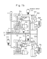
- Figs. 1a and 1b show a mechanical arrangement of an apparatus which supports a carrosserie or car body.
- An oil pressure pump 1 which is of radial type, is disposed within an engine room, and is driven for rotation by an onboard engine, not shown, thus drawing an oil from a reservoir 2 and discharging a given flow rate of oil to a high pressure port 3 at a rotational speed equal to or greater than a given value.
- High pressure port 3 of the radial pump is connected to an accumulator 4 which serves suppressing pulsations, to a main check valve 50 and to a relief valve 60m.
- a high pressure oil from the port 3 is fed to a high pressure piping 8 through the valve 50.
- the check valve 50 blocks a reverse flow of the oil from the piping 8 to the port 3 whenever the port 3 assumes a lower pressure than the piping
- the relief valve 60m drains the port 3 to a reservoir return piping 11, which represents one of the port 3 assumes a greater than a given value, thus maintaining the pressure of the port 3 substantially at a given pressure.
- the high pressure feed piping 8 communicates with a front wheel high pressure feed piping 6 which feeds a high pressure to front wheel suspensions 100fL, 100fr, and a rear wheel high pressure feed piping 9 which feeds high pressure to rear wheel suspensions 100rL, 100rr.
- the piping 6 communicates with an accumulator 7 for the front wheels while the piping 9 commumicates with an accumulator 10 for the rear wheels.
- the piping 6 is also connected to a pressure control valve 80fr through an oil filter, and the valve 80fr is effective to regulate or reduce the pressure from the piping 6, which will be hereinafter referred to as a front wheel line pressure, to a required pressure before supplying it to a cut valve 70fr and a relief valve 60fr.
- the required pressure is substantially proportional to a current level which is used to energize an electrical coil of the valve 80fr and represents a suspension sustain pressure.
- the cut valve 70fr interrupts a communication between the output port 84(to the suspension) of the pressure control valve 80fr and a hollow piston rod 102fr associated with a shock absorber 101fr of the suspension 100 fr, thus preventing the pressure of the piston rod 102fr from being released to the pressure control valve 80fr.
- the cut valve 70fr allows the output pressure from th pressure control valve 80fr to be directly fed to the piston rod 102fr.
- the relief valve 60fr restricts the internal pressure of the shock absorber 101fr at or below an upper limit. Specifically, when the suspension sustain pressure from the output port 84 of the pressure control valve 80fr exceeds a given high pressure, the output port 84 is drained to the reservoir return path or piping 11, thus maintaining the output port of the valve 80fr substantially at or below the given high pressure.
- the relief valve 60fr is also effective to provide a buffering action upon the transmission to the pressure control valve 80fr of any shocking rise in the internal pressure of the shock absorber 101fr, as when a front, right wheel of the vehicle strikes against a bump on the road. In response to such rise, the internal pressure of the shock absorber 101fr is drained to the reservoir return path 11 through the piston rod 100fr and the cut valve.
- the suspension 100fr essentially comprises the shock absorber 101fr and a coiled suspension spring 119fr, and operate to maintain a car body at an elevation relative to the front, right wheel, which corresponds to the pressure supplied to the shock absorber 101fr from the output port 84 of the pressure control valve 80fr through the piston rod 102fr, or a pressure which is regulated by the pressure control valve 80fr or the suspension sustain pressure.
- the sustain pressure fed to the shock absorber 101fr is detected by a pressure sensor 13fr, which produces an analog signal representing a detected sustain pressure.
- a vehicle elevation sensor 15fr is mounted on the car body adjacent to the suspension 100fr, and includes a rotor connected to link which is coupled to the front, right wheel. In this manner, the sensor 15fr, produces a digital data representing the elevation of a car body with respect to the front, right wheel.
- a suspension 100fL associated with a front, left wheel is equipped with a pressure control valve 80fL, a cut valve 70fL, a relief valve 60fL, a vehicle elevation sensor 50fL, and a pressure sensor 13fL.
- the pressure control valve 80fL is connected to the front wheel high pressure feed piping 6, thus feeding a required pressure to the piston rod 102fL of the shock absorber 101fL of the suspension 100fL.
- a suspension 100rr associated with a rear, right wheel is equipped with a pressure control valve 80rr, a cut valve 70rr, a relief valve 60rr, a vehicle elevation sensor 15rr and a pressure sensor 13rr.
- the valve 80rr is connected to the rear wheel high pressure feed piping 9, feeding a required pressure to the piston rod 102rr of a shock absorber 101rr of the suspension 100rr.
- a suspension 100rL associated with a rear, left wheel is equipped with a pressure control valve 80rL, a cut valve 70rL, a relief valve 60rL, a vehicle elevation sensor 15rL and a pressure sensor 13rL.
- the pressure control valve 80rL is connected to the rear wheel high pressure feed piping 9, feeding a required pressure to the piston rod 102rL of a shock absorber 101rL of the suspension 100rL.
- an engine is mounted on the front wheel side, and accordingly the pump 1 is also mounted on the front wheel side or in the engine room, whereby the length of pipings from the pump 1 to the rear wheel suspensions 100fr, 100fL. Accordingly, a pressure drop caused by the piping path is greater for the rear wheels, and if an oil leakage occurs in the piping, the pressure drop will be greatest for the rear wheels. Accordingly, a line pressure detecting sensor 13rm is connected to the rear wheel high pressure feed piping 9. On the other hand, the pressure of the reservoir return path 11 will be lowest at its end located nearer the reservoir 1, and will tend to increase in a direction away from the reservoir 2. Accordingly, the pressure of the reservoir return path 11 is also detected by a pressure sensor 13rr which is located toward the rear wheel.
- the piping is connected to a bypass valve 120, which is effective to regulate a pressure in the high pressure feed piping 8 to a valve 4 which corresponds to a current level used to energize an electrical coil of the valve 120, thus obtaining a required line pressure.
- a bypass valve 120 which is effective to regulate a pressure in the high pressure feed piping 8 to a valve 4 which corresponds to a current level used to energize an electrical coil of the valve 120, thus obtaining a required line pressure.
- Fig. 2 shows a longitudinal section, to an enlarged scale, of the suspension 100fr.
- a piston 103 is fixedly mounted on the piston rod 102fr of the shock absorber lolfr, and extends through an inner sleeve 104 to divide its interior into an upper chamber 105 and a lower chamber 106.
- An oil pump pressure which represents the suspension sustain pressure is fed to the piston rod 102fr from the output port of the cut valve 70fr, which pressure is passed through a side opening 107 in the piston rod 102fr to be applied to the upper chamber 105 disposed inside the inner sleeve 104, and thence passed through a vertical through-opening 108 formed in the piston rod 103 to be applied to lower chamber 106.
- a sustain pressure which is proportional to the product of the pressure applied to the lower chamber 106 and cross-sectional area (the square of the rod radius multiplied by ⁇ ) of the piston rod 102fr is applied to the piston rod 102fr.
- the lower chamber 106 communicates with a lower space 110 in an attenuator valve unit 109, which has an upper space that is divided by a piston 111 into a lower chamber 112 and an upper chamber 113.
- An oil from the lower space 110 passes through the valve unit 109 into the lower chamber 112 while a high pressure gas is confines in the upper chamber 113.
- the pressure in the lower chamber 112 rises, which in turn causes the piston 111 to be raised, allowing the latter to assume a position which corresponds to a loading upon the car body.
- a seal between the inner sleeve 104 and the piston rod 102fr prevents any substantial oil leakage from the inner sleeve 104 to an outer sleeve 114.
- it is desirable that such seal exhibits a sealing characteristic which permits a very limited amount of oil leakage during the vertical movement of the piston rod 102fr in order to reduce a resistance presented to such movement of the rod 102fr.
- a drain 14fr (Fig 1a) which is open to the atmosphere and a drain return piping 12 (Fig 1a), which represents a second return path
- the reservoir 2 is equipped with a level sensor 28 (Fig. 1a), which produces an oil shortage signal when the oil level within the reservoir 2 is below a lower limit.
- suspensions 100fL 100rr and 100rL are constructed in substantially the same manner as the suspension 100fr mentioned above.
- Fig. 3 shows a longitudinal section, to an enlarged scale, of the pressure control valve 80fr. It includes a sleeve 81, which is centrally formed with a spool receiving opening, the inner surface of which is formed with an annular groove 83 communicating with a line pressure port 82 and another annular groove 86 communicating with a low pressure port 85.
- An output port 84 opens into the sleeve at a location intermediate the both annular grooves 83, 86.
- a spool 90 is inserted into the spool receiving opening, and intermediate its length, its peripheral surface is formed with an annular groove 91 having a width which corresponds to the distance between a right edge of the groove 83 and a left edge of the groove 86.
- the left end of the spool 90 is formed with a valve receiving opening, which communicates with the groove 91, and into which a valve element 93 is inserted and held in place by a coiled compression spring 92.
- the valve element 93 is centrally formed with an orifice extending therethrough, which provides a communication between the space in which the groove 91 and hence the output port 84 is located and the space in which the valve element 93 and the spring 92 are received Accordingly, at its left end, the spool 90 is subject to a pressure from the output port 84 or a regulated pressure which is applied to the suspension 100fr, whereby it is urged to the right.
- valve element 93 In the event a pressure from the output port 84 increases in an impulse manner, the valve element 93 is driven to the left against the resilience of the spring 92, creating a buffering space to the right of the valve element 93. Accordingly, when the pressure from the output port 94 rises in an impulse manner, such pressure rise is not immediately applied to the left end face of the spool 90, and thus the valve element 93 provides a buffering action upon a movement of the spool 90 to the right in response to an impulse-like pressure rise, or pressure surge from the output port 84. Conversely, it also exerts a buffering action upon a movement of the spool 90 to the left in response to an impulse-like pressure fall from the output port 84.
- the right end face of the spool 90 is subject to a pressure from a target pressure space 88 communicating with a high pressure port 87, which pressure is supplied through an orifice 88f, whereby the spool 90 is urged to the left.
- a lime pressure is fed to the high pressure port 87 while the target pressure space 88 communicates with a low pressure port 89 through a channel 94, the channel opening of which is determined by a needle valve 95.
- the target pressure space 88 which communicates with the high pressure port 87 through the orifice 88f assumes the line pressure of the port 87, whereby the spool 90 is driven to the left, allowing the groove 91 in the spool 90 to communicate with the groove 83 or the line pressure port 82 thus causing the pressure of the port 91 or output port 84 to rise which is then transmitted to the left of the valve element 93, thus imparting a rightward driving force to the left end of the spool 90.
- the needle valve 95 is located to leave the channel 94 fully open, the pressure from the space 88 will be substantially reduced below the line pressure from the high pressure port 87 because of the restriction presented by the orifice 88f.
- the spool 90 moves to the right, allowing the groove 91 in the spool 90 to communicate with the groove 86 or the low pressure port 85, reducing the pressure in the port 91 or the output port 84.
- Such pressure is transmitted to the left of the valve element 93, thus reducing the rightward driving force which is applied to the left end of the spool 90.
- the spool 90 assumes a position where the pressure from the target pressure which is substantially proportional to the pressure from the target pressure space 88 appears at the output port 84.
- the pressure in the target pressure space 88 is determined by the position of the needle valve 95, which is in turn substantially in inverse proportion to the distance of the needle valve 95 from the channel 94, and hence there appears at the output port 84 a pressure which is substantially inversely proportional to the distance of the needle valve 95.
- a stationary core 96 of magnetizable material is shaped to allow the needle valve 95 to extend therethrough, and has a right end which is in the form of truncated cone, which is opposed by a conical end face of a plunger 97, also formed of a magnetizable material, which defines an opening having a closed bottom.
- the needle valve 95 is secured to the plunger 97.
- the core 96 and the plunger 97 extend into a bobbin which carries an electrical coil 99 thereon.
- the left end of the needle valve 95 is subject to a pressure from the target pressure space 88 which acts to drive it to the right while the right end of the needle valve 95 is subject to the atmospheric pressure through a low pressure port 98c which is open to the atmosphere, so that the needle valve 95 will be driven to the right by the pressure from the target pressure space 88 with a force which depends on the magnitude of such pressure (it will be noted that this corresponds to the position of the needle valve 95).
- the needle valve 95 is spaced from the channel 94 by a distance which is virtually inversely proportional to the current level which is used to energize the coil 99.
- One of the core and the plunger is shaped as a truncated cone while the other is shaped as a complementary conical opening in order to achieve a linear relationship between the current level and distance.
- the pressure of the suspension 100fr increases and consequently the pressure of the output port 84 of the pressure control valve 80fr increases to drive the spool 90 toward pressure down direction (toward right in Fig. 3), substantially eliminating a transmission of an up impact of the wheel to the body of the vehicle.
- the movement of the spool 90 toward right causes an increase of the pressure in the target pressure space 88.
- the pressure in the target pressure space 88 is applied to the top of the needle valve 95 through the channel 94.
- the needle valve 95 goes back (moves toward right) to have a space from the channel 94.
- the communication from the target pressure space 88 to the return path 11 through the channel 94 and the low pressure port 89 is increased
- the wheel falls down and consequently the pressure of the suspension 100fr decreases, whereby the pressure of the output port 84 of the pressure control valve 80fr decreases to drive the spool 90 toward a pressure up direction (toward left in Fig. 3), substantially eliminating a transmission of a down impact of the wheel to the body of the vehicle.
- the movement of the spool 90 toward left causes a decrease of the pressure in the target pressure space 88, whereby the needle valve 95 goes forward (toward left) to close the channel 94 and consequently the communication of the target pressure space 88 to the return path 11 decreases.
- the pressure in the target pressure space 88 increases.
- the main check valve 50 supplies oil from the high pressure port 3 to the high pressure piping 98, but blocks a reverse flow from the piping 8 to the port 3.
- the relief valve 60m suppresses the pressure at the high pressure port 3 or the high pressure piping 8 at or below a given high pressure, and in the event a high pressure surge is applied to the port 3, it releases such surge to the return path 11, thus buffering the transmission of a pressure surge to the piping 8.
- the bypass valve 120 controls the pressure of the rear wheel high pressure feed piping 9 substantially linearly in a given range, and maintains the pressure of the piping 9 at a given value during a steady-state operation.
- the constant pressure control takes place by controlling the current level 0 the bypass valve 120 with reference to a pressure detected by the pressure sensor 13rm.
- the valve releases it to the return path 11, thus buffering its transmission to the piping 8.
- the ignition switch is open, and the engine as well as the pump 1 cease to operate, the energization is interrupted, whereby the piping 9 is made to communicate with the return path 11, thus decompressing,
- Pressure control valves 80fr, 80fL, 80rr and 80rL deliver the required sustain pressure to output ports (84) by controlling the current level of the electrical coil (99) so that the required sustain pressure is applied to the suspension through the suspension pressure control.
- the transmission of a pressure surge to the suspension is buffered, thus suppressing a hunting of the pressure controlling spool (91), thus allowing the pressure applied to the suspension to be stabilized.
- Cut valves 70fr, 70fL 70rr and 70rL interrupt the suspension pressure feeding line between the output port 84 of the pressure control valve and the suspension to prevent the pressure from being released from the suspension when the line pressure (front wheel high pressure feed piping 9) is below a given low pressure, and fully opens the feed line whenever the line pressure is equal to or greater than the given low pressure. In this manner, the suspension pressure is automatically prevented from going abnormally low value when the line pressure is low.
- Relief valves 60fr, 60fL 60rr and 60rL limit the pressure of the suspension feed line between the output port 84 of the pressure control valve and the suspension or principally the suspension pressure to less than an upper limit so that any high pressure surge applied to the feed line or the suspension as when the vehicle is bumped or a load of high mass is thrown onto the vehicle may be released to the return path, thus buffering the impact upon the suspension and enhancing the durability of the feed line and its connected mechanical elements.
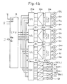
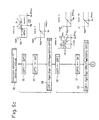
- Figs. 4a and 4b show an electrical control system which determines the driving condition and the attitude of a vehicle in response to the status of various switches and sensors mounted on the vehicle and establishes required pressures in the individual suspensions shown in Figs. 1a and 1b so as to bring the attitude of the car body to a desired one.
- Vehicle elevation sensors 15fL, 15fr, 15rL and 15rr are connected to a low pass filter 31a, which cuts off high frequency components or noises in an analog signal which is detected by the respective sensors, and smoothes a relatively high frequency component which is shaped to provide a vehicle elevation signal, which is then amplifies to reach a given range of levels by an amplifier 30a before it is applied to A/D converter (IC) 29a
- IC A/D converter
- Pressure sensors 13fL, 13fr, 13rL and 13rr which detect the oil pressure of the individual suspensions are connected to a low pass filter 31b, which cuts off high frequency components or noises from an analog signal representing a pressure detected by individual pressure sensors and smoothes a relatively high frequency component, which is then shaped to provide a pressure signal, that is in turn amplified to reach a given range of levels by an amplifier 30b before it is applied to A/D converter (IC) 29b.
- IC A/D converter
- Pressure sensor 13rm which detects the pressure of the rear wheel high pressure feed piping 9 and pressure sensor 13rt which detects the pressure of the rear wheel side of the return path 11 are connected to a low pass filter 31c, which cuts off high frequency components or noises from an analog signal representing a pressure detected by the respective pressure sensors and smoothes a relatively high frequency component to provide a shapes pressure signal, which is then amplified to reach a given range of levels by an amplifier 30c before it is applied to A/D converter (IC) 29c.
- IC A/D converter
- a longitudinal acceleration sensor 16p which detects the acceleration in the fore-and-aft direction of the vehicle (a positive value representing an acceleration and a negative value representing acceleration) and a lateral acceleration sensor 16r which detects the acceleration in the lateral direction of a vehicle ( a positive value representing an acceleration directed from left to right and a negative value representing an acceleration directed from right to left) are also connected to the low pass filter 31c, which cuts off high frequency components or noises from an analog signal representing a pressure detected by the respective acceleration sensor and smoothes a relatively high frequency component to provide a shaped acceleration signal, which is then amplified to reach a given range of levels by an amplifier 30c before it is applied to A/D converter (IC) 29c.
- IC A/D converter
- the electrical coils 99 of the pressure control valves 80fL, 80fr, 80rL and 80rr as well as the electrical coil 129 of the bypass valve 120 are connected to coil drivers 33.
- Each driver 33 comprises a switching circuit which is operative to energize individual electrical coil, and a current detector which detects the current level of the respective coil and produce an analog signal representing same.
- a duty controller (IC) 32 provides an ON(energization)/OFF(deenergization) command.
- the driver 33 completes the connection between a selected coil and the output of a constant current circuit.
- the OFF command causes such connection to be disconnected
- Analog voltages representing the current levels detected are normally fed to A/D converter (IC) 29c.
- the duty controller 32 receives data representing the current level to be used in the energization for each of the electrical coils (which are associated with the pressure control valves and the bypass valve) and which is supplied from a microprocessor (hereafter abbreviated as CPU) 18 and stores it in a latch feeds a detected current level to CPU 18 through A/D converter (IC) 29c for feedback purpose, controls the duty cycle so as to achieve the current level specified by CPU 18, and deliver a time sequence of ON/OFF commands which corresponds to the duty cycle to the coil driver 33.
- a microprocessor hereafter abbreviated as CPU
- IC A/D converter
- Each of A/D converters 29a to 29c is formed by an integrated circuit internally housing a sample-and-hold circuit having four input ports, except for the converter 29c which is fed with analog voltages from the coil driver 33. representing detected current levels of the pressure control valve and the bypass valve.
- the converter samples an analog voltage at its input port in its sample-and-hold circuit and converts it to digital data which may be vehicle elevation, pressure or acceleration data which is then transferred to CPU 18 serially in synchronism with a clock pulse fed from CPU 18.
- the sampling, the conversion and the transfer operation take place successively with respect to the input ports 1 to 4.
- a single conversion command from CPU 18 is effective to cause the converter to sample four analog voltages at its input ports successively and to transfer resulting digital data serially to CPU 18.
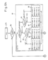
- CPU 18 is arranged to communicate data with CPU 17, which receives a number of signals including an open (L:no pressure control command)/ close(H:command) signal from a command switch CSW which commands a pressure control of the suspension; a signal from a brake pedal having H(depressed)/L(no depression) level; an open(L)/ close(H) signal from the ignition switch 20; pulses from a vehicle speed synchronized pulse generator 25 which generates one pulse per incremental angle of rotation of an output shaft of an onboard transmission; a first set and a second set of pulses from a rotary encoder 26 which produces one pulse per incremental angle of rotation of a steering shaft, the pulses in the second set being 90° phase displaced from the pulses in the first set; data generated by an absolute encoder 27 coupled to the rotary shaft of a throttle valve of the engine and producing 3-bit data representing the opening of the throttle valve; and a signal from a level sensor 28 which detects the oil level in the reservoir 2(H:below a lower limit level, L:
- signals from other sensors are fed to CPU 17 through an input/output circuit 34.
- An indicator such as a warning light is also connected to the input/output circuit 34, and is operated by CPU 17 through the input/output circuit 34 in the event the occurrence of any abnormality in the pressure control of the suspension is determined
- An onboard battery 19 is connected to a backup poor supply circuit 23 having a reduced capacity and which feeds a constant voltage to CPU 17. Accordingly, as long as the battery 19 provides an output voltage which is at or above a given value, CPU 17 is normally maintained operative to preserve data in its internal memories.
- the onboard battery 19 is also connected through the ignition switch 20 to a constant voltage power supply circuit 21 having an increased capacity, which deliver constant voltages of low level to electronic elements and circuits such as CPU 18 and also delivers constant voltages of high levels to selected circuits such as low pass filters 31a to 31c and input/output circuit 34.
- the ignition switch 20 is shunted by a self holding contact of a relay 22, which may be turned ON and OFF by CPU 17.
- CPU's 17 and 18 has respective programs stored therein which controls the pressures of the suspensions.
- CPU 18 operates according to such program, principally operating to read values detected by vehicle elevation sensors 15fL 15fr, 15rL, 15rr, the pressure sensors 13fL, I3fr, 13rL, 13rr, 13rm, 13rt and the onboard longitudinal and lateral acceleration sensors 16t, 16r and to control the current level which is used to energize the electrical coils 99, 129 of the pressure control valves 80fL, 80fr, 80rr and the bypass valve 120.
- CPU 17 operates to establish or terminate the line pressure for the suspension system Figs. 1a and 1b), to determine the driving condition of the vehicle, and to calculate pressures required of the suspension in order to establish a vehicle elevation and vehicle attitude which are appropriate to the result of the determination during an interval from the turn-ON the turn-OFF of the ignition switch 20 as well as during a short time internal thereafter.
- CPU 17 receives various detected values from CPU 18 in order to determine the driving condition of a vehicle, and delivers the current level required for the energization to estabib the required pressure to CPU 18.
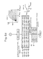
- Table 1 register data entered description of data entered PFLo PfLo initial pressure of shock absorber 101fL PFRo Pfro initial pressure of shock absorber 101fr PRLo PrLo initial pressure of shock absorber 101rL PRRo Prro initial pressure of shock absorber 101rr DPH Dph rear wheel pressure of high pressure line 8 DPL DpL rear wheel pressure of return path 11 SS Ss steering angular velocity TP Tp throttle opening St St period during which CPU 17 reads a detected value VS Vs vehicle speed PG Pg longitudinal acceleration(sensor 16t) RG Rg lateral acceleration(sensor 16r) DFL DfL vehicle elevation to front, left wheel DFR Dfr vehicle elevation to front, right wheel DRL DrL vehicle elevation to rear, left wheel DRR Drr vehicle elevation to rear, right wheel HT Ht heave target value PT Pt pitching target value RT Rt rolling target value WT Wt warp target value .. .. ............................
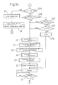
- step 1 when the power supply is turned on (step 1 where the backup power supply circuit 23 is activated to produce constant voltages or the battery 19 is mounted on the vehicle), CPU 17 initializes its internal registers, counters and timers, and deliver signal levels at its output ports which establish initial standby conditions (this involves no energization of mechanical elements) (step 2).
- step 3 more precisely, if the command switch CSW and the ignition switch 20 are closed), and if it remains open, it waits for the switch to be closed
- the coil of the relay 22 is energized to close the self-holding contacts (step 4).
- the power supply circuit 21 having an increased capacity is connected to the battery 19, and operates to deliver constant voltages of low level to electronic components such as CPU 18 and other electrical circuits and to deliver constant voltages of high level to low pass filters 31a to 31c and input/output circuit 34.
- CPU 18 is also electrically activated to be operative. Since the relay contacts are closed to maintain the power supply circuit 21 connected to the battery 19, the electrical circuit system shown in Figs. 4a and 4b are entirely electrically activated to remain operative if the ignition switch 20 is subsequently opened unless the relay 22 is turned OFF by CPU 17.
- CPU 17 After energizing the relay coil, CPU 17 enables an interrupt operation which is executed in response to an oncoming pulse signal to its interrupt input ports ASRO to ASR2 (step 5).
- the interrupt operation will be initially described Considering an interrupt operation which takes place in response to a pulse generated by the vehicle speed synchronized pulse generator 25 (applied to input port ASR2), as the generator 25 generates a single pulse, CPU 17 advances to an interrupt operation (ASR2) where the content of a vehicle speed measuring register is read and the register is re-started. A vehicle speed is calculated on the basis of the content read (representing the time period for the pulses), a weighted mean Vs is derived over previous several values of the vehicle speed calculated which have been stored and the weighted mean written into a vehicle speed register VS, and then the operation returns to the main program. As a result of the execution of the interrupt operation (ASR2), data Vs representing the prevailing vehicle speed or a value which is smoothed over previous calculated values in the time sequence is always maintained in the vehicle speed register VS.
- ASR2 interrupt operation
- CPU 17 When CPU 17 has enabled the interrupt operation, it examines if CPU 18 issues a ready signal (step 6).
- CPU 18 then delivers a maximum current level data which causes the full closure of the bypass valve 120, and then commands the energization of the bypass valve 120.
- the current level for all of the pressure control valves 80fL, 80fr, 80rL and 80rr are equal to zero, and a pressure equivalent to that prevailing in the return path 11 is delivered to its output port (84). Since the bypass valve 120 is in full closure and since the ignition switch 20 is closed and the pump 1 is being drive for rotation the pressure in the high pressure feed piping 8, the front wheel high pressure feed piping 6 (accumulator 7) and the rear wheel high pressure feed piping 9 (accumulator 10) begins to rise.
- CPU 18 reads values detected by vehicle elevation sensors 15fL, 15fr, 15rL 15rr, the pressure sensors 13fL, 13fr, 13rL 13rr, 13rm, 13rt, longitudinal acceleration sensor 16p and lateral acceleration sensor 16r as well as the current levels detected from the coil drivers 33, all of which are used to update its internal registers.
- CPU 17 delivers data representing the current levels of the pressure control valves 80fL, 80fr, 80rL, 80rr and the bypass valve 120, CPU 18 transfers it to the duty controller 32.
- CPU 17 finds at step 6 that CPU 18 delivers a busy signal, it loops around stnsby loop (steps 8 to 11). If CPU 18 delivers a ready signal, the standby looping is terminated (step 13).
- CPU 17 requests CPU 18 to transfer detected pressure data Dph from the pressure sensor 13rm, and then receives it and writes it into register DPH (step 14), and then examines if the detected pressure Dph representing the rear wheel side pressure of the high pressure feed piping 8 has become equal to or greater than a given value Pph, which is less than a given low pressure at which the cut valves 70fL, 70fr, 70rL, 70rr begin to be opened or if the line pressure has risen to a degree (step 15). If the line pressure has not risen, the operation returns to step 6.
- CPU 17 commands CPU 18 to transfer data pfLo, Pfro, prLo, Prro representing the initial pressures detected by the pressure sensors 13fL, 13fr, 13rL, 13rr, which are then written into registers PFLo, PFRo, PRLo, PRRo upon receipt (step 16).
- the content PfLo, Pfro, PrLo, Prro of the registers PFLo, PFRo, PRLo, PRRo are used to access data representing the current level which is required to achieve a required pressures and which are stored in a given region (Table 1) of the internal ROM, thus the reading from the Table 1 the current level IhfL which is required to the coil 99 to deliver the pressure pfLo to the output port 84 of the pressure control valve 80fL; the current level Ihfr which is required to deliver the pressure Pfro to the output port of the pressure control valve 80fr; the current level AliL required to deliver the pressure PrLo to the output port of the pressure control valve 80rL and the current level Negr required to deliver the pressure Prro to the output port of the pressure control valve 80rr, all of which are written into output registers IHfL IHfr, IHrL and IHrr (step 17). Data in these output registers are transferred to CPU 18, which delivers them to the duty controller 32 upon receipt.
- the duty controller 32 stores data representing the current levels IhfL Ihfr, JackpotL and Bitr in respective latches and then regulates the ON/OFF duty of the coil 99 associated with the pressure control valve 80fL so that the current level which is fed back from the pressure control valve 80fL through CPU 18 becomes equal to IhfL.
- a time sequence of ON/OFF commands which corresponds to such duty is applied to the coil driver 33 so as to control the pressure control valve 80fL.
- the duty control of the remaining pressure control valves 80fr, 80e, 80rr takes place in a similar manner, applying a time sequence of ON/OFF commands to the coil driver 33.
- the pressure control valves 80fL, 80fr, 80rL 80rr deliver the pressures which are substantially equal to PfLo, Pfro, PrLo, Prro, to the output port (84) if the line pressure is equal to or greater than a given low pressure.
- the command switch CSW when the command switch CSW is closed and the ignition switch 20 changes from its open (the engine and the pump 1 not operating) to its closed (the pump 1 being driven) condition and the cut valves 70fL, 70fr, 70rL, 70rr are open to achieve the line pressure which is equal to or greater than the given low pressure and the oil pressure lines of the suspension communicate with the output ports of the pressure control valve or when the ignition switch 20 is closed and the command switch CSW changes from its open condition to its closed condition, the pressures delivered by the pressure control valves will be substantially equal to the suspension pressures, preventing a rapid pressure variation in the suspensions. In other words, an impulse-like change in the attitude of the vehicle is avoided.
- the above description covers the establishment of initial output pressures from the pressure control valves 80fL, 80fr, 80rL, 80rr when the command switch CSW is closed and the ignition switch 20 is changed from its open to its closed condition or immediately after the engine has started. Also the above description covers the establishment of initial output pressures from the pressure control valves 80fL, 80fr, 80rL, 80rr when the ignition switch 20 is closed and the command switch CSW is changed from its open to its closed condition
- CPU 17 starts timer ST which provides a time limit ST (step 19).
- the content of the register ST is represented by ST, and data ST representing a second time period which is longer than the first time period during which CPU 18 reads detected values is written into the register ST.
- CPU 17 Upon starting the timer ST, CPU 17 reads the status (step 20). Specifically, the open/close signal of switch which detects the depression of the brake pedal, data representing the throttle opening from the absolute encoder 27, and a signal from the reservoir level detecting switch 28 are read and written into internal registers.
- CPU 17 commands CPU 18 to transfer detected data, whereby data DfL, Dfr, DrL, Drr representing the vehicle elevations detected by the sensors 15fL, 15fr, 15rL, 15rr, data PFL, Pfr, PrL, Prr, Prm, Prt representing the pressures detected by the sensors 13fL, 13fr, 13rL, 13rr, 13rm, 13rt, and data representing the detected current level of the pressure control valves 80fL, 80fr, 80rL, 80rr and the bypass valve 120 are transferred to CPU 17, which then write them into internal registers. A reference to these read value is made to render a decision concerning the abnormality/normality, and in the event an abnormality is found, the program proceeds to step 8.
- CPU 17 executes a line pressure control (LPC). Specifically, it derives the absolute value and the polarity (high/low) of a deviation of a detected line pressure Prm with respect to a reference pressure which is a fixed value slightly less than a relief pressure (which is referred to as a given high pressure) of the relief valve 60m, and adds a correction value which reduces the deviation to zero to the current level that is currently fed to the bypass valve 120 to derive a new current level for the bypass valve 120, which is then written into an output register. The content of this output register is transferred to CPU 18 at a subsequent step 36.
- LPC line pressure control
- the current level of the bypass valve 120 will be controlled so that the pressure of the rear wheel high pressure feed piping 9 assumes a given value slightly less than the relief pressure (the given high pressure) of the relief valve 60m.
- step 23 the relay 22 is deenergized and the interrupt operations (ASR0 to ASR2) are inhibited.
- the bypass valve 120 is initially deenergized so that it becomes fully open, thus releasing the line pressure to the return path 11.
- CPU 17 operates to deenergize the pressure control valves 80fL, 80fr, 80rL, 80rr.
- CPU 17 examines if "tests is indicated or not, and if "test” is indicated CPU 17 examines if the vehicle speed Vs is lower than a predetermined value A or not (steps 22B to 22D). Namely CPU 17 examines if test indication switches TSW1 and TSW2 are closed (steps 22b and 22B), and if they are closed CPU 17 examines if the vehicle speed Vs is lower than A or not (step 22D).
- CPU 17 executes a subroutine "test” (CTS), the content of which is shown in Figs. 6h and 6i and described later.
- CTS subroutine "test”
- CPU 17 executes "output" (subroutine 36) in which CPU 17 supplies CPU 18 with pressure indication data calculated in the "test" subroutine CTS and assigned to the pressure control valves 80fL, 80fr, 80rL, 80rr.
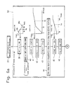
- CPU 17 calculates a parameter representing the running condition of the vehicle (step 25). Then CPU 17 executes "calculation of vehicle elevation deviation” (step 31) where a deviation of the actual vehicle elevation with respect to a target elevation is calculated, and a correction to be applied to the suspension pressures, hereafter referred to as a first correction for each of the suspensions, is calculated which reduces the deviation to zero.
- a correction to be applied to the suspension pressures hereafter referred to as a first correction for each of the suspensions
- step 31 “Calculation of vehicle elevation deviation” (step 31) is followed by “predictive calculation of pitching/rolling” (step 32) where a correctin to the suspension pressure (which is hereafter referred to a second correction for each of the suspensions), is calculated in accordance with longitudinal and lateral accelerations which the vehicle actually experiences, the deriving an interim value" initial suspension pressure (PfLo, Pfro, PrLo, Prro) + first correction + second correction".
- initial suspension pressure PfLo, Pfro, PrLo, Prro
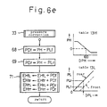
- CPU 17 then executes "pressure correction" (step 33) where the "interim value” mentioned above is again corrected in accordance with the line pressure (high pressure) detected by the pressure sensor 13rm and the return pressure (low pressure) detected by the pressure sensor 13rt. The detail of this operation will be described later in connection with Fig. 6e.
- CPU 17 then effects "pressure/current conversion” (step 34) where the corrected “interim value” for each of the suspensions is converted into the current level which is to be used in energizing the pressure control valves (80fL, 80fr, 80rL, 80rr). The detail of this operation will be described later in connection with Fig. 6f.
- CPU 17 then effects "correction of warp" (step 35) where a turning warp correction, representing a correction to be applied to the current level, which depends on the lateral acceleration Rg and the steering rate Ss, is calculated and is added to the current level to be applied to the pressure control valve.
- a turning warp correction representing a correction to be applied to the current level, which depends on the lateral acceleration Rg and the steering rate Ss, is calculated and is added to the current level to be applied to the pressure control valve.
- CPU 17 then comes to "output" (step 36) where it delivers the current levels to be applied to the respective pressure control valves which are calculated in the manner mentioned above to CPU 18 so as to be fed to the individual pressure control valves, and also deliver the current level which is to be applied to the bypass valve 120 as calculated by the "line pressure control” (LPC) to CPU 18 so as to be fed to the bypass valve 120.
- LPC line pressure control
- CPU 17 has completed all the tasks which are contained in one cycle of the suspension pressure control.
- CPU 17 then waits for the timer ST to time out (step 37), whereupon it returns to step 19, re-starting the timer ST and initiating the execution of tasks in the suspentsion pressure control of next cycle.
- CPU 17 demands CPU 18 to effect a transfer of detected values from the sensors with ST period (second period) (subroutine 20).
- CPU 18 transfers sensor data to CPU 17, which is a smoothed version of a weighted mean of several past values which are read during the first period.
- Data representing the current levels which are to be applied to the respective pressure control valves and the bypass valves 120 are transferred form CPU 17 to CPU 18 with the ST period.
- CPU 18 deliver such current level data to the duty controller 32, where they are latched.
- the duty controller 32 controls the duty cycle of the energization so that the actual current levels of the pressure control valves and the bypass valve 120 as detected by the coil drivers 33, coincide with the target current levels while updating the target current levels themselves with the ST period.
- data DfL, Dfr, DrL, Drr which are contents of the registers DFL, DFR, DRL, DRR, representing vehicle elevations detected by the sensors 15fL, 15fr, 15rL, 15rr are used to determine an overall vehicle heave (height) DHT, pitch DPT representing a difference in the vehicle elevation between the front wheel and the rear wheel, a roll DRT representing a difference in the vehicle elevation between the right wheel and the left wheel, a warp DWT representing a difference between the sum of the vehicle elevations of the front, right wheel and the rear, left wheel and the sum of the vehicle elevations of the front, left wheel and the rear, right wheel.
- the vehicle elevations of the respective wheels as represented by the content of the registers DFL, DFR, DRL, DRR are converted into a heave DHT, a pitch DPT, a roll DRT, a warp DWT, which are attitude parameters of the overall vehicle.
- DHT DFL+DFR+DRL+DRR
- DPT -(DFL+DFR) + (DRL+DRR)
- DRT (DFL-DFR) + (DRL-DRR)
- DWT (DFL-DFR) - (DRL-DRR)
- the calculation of the parameter DHT is executed in "calculation of heave error CH" (subroutine 50), the calculation of the parameter DPT is executed in “calculation of pitching error CP" (subroutine 51), the calculation of the parameter DRT is executed in “calculation of rolling error CR” (subroutine 52), and the calculation of the parameter DWT is executed in "calculation of heave error CW" (subroutine 53).
- a target heave Ht is derived from the vehicle speed Vs and an indication of "normal” or “high” which is determined by a closure state of a height indication switch HSW by accessing an internal ROM (table 2H) of the CPU 17 with "normal” or “high” and Vs, the target heave Ht is written in the heave target register HT, and a heave error of the calculated heave DHT with respect to the target heave Ht is calculated.
- PID proportional, intergral and differential
- a target pitch Pt is derived from the longitudinal acceleration Pg, and the pitch error of the calculated pitch DPT with respect to the target pitch Pt is calculated, and the calculated pitch error is subject to PID processing, thus deriving a pitch correction CP which depends on the particular pitch error.
- a target roll Rt is derived from the lateral acceleration Rg, and a roll error of the calculated roll DRT with respect to the target roll Rt is calculated, which is then subjects to PID processing, thus deriving a roll correction CR which depends on the particular roll error.
- a target warp Wt is initially assumed to be zero, and the warp error of the calculated warp DWT with respect to the target warp Wt is calculated, and is then subject to PID processing, hus deriving a warp correction CW which depends on the particular warp error.
- the warp error which is equivalent to DWT since the target warp is assumed to be zero has a absolute value which is less tha a given value representing a permissible range
- the warp error which is subject to PID processing is made equal to zero.
- the warp error which is subject to PID processing is changed to -DWT.
- CPU 17 initially reads a target heave Ht corresponding to the vehicle speed Vs from a region (table 2H) of the internal ROM and writes it into a heave target register Ht (step 39).
- the target heave Ht which is given in correspondence to the vehicle speed Vs assumes a high value Ht 1 at low vehicle speed Vs equal to or less than 80 Km/h, and a low value Ht2 for high vehicle speed Vs equal to or greater than 120 Km/h, the target changes linearly with respect to the vehicle speed Vs, although it may follow a curve.
- the purpose of linearly changing the target is to prevent a degradation in th stability of the vehicle elevation as a result of a frequent change of the vehicle speed at high speeds, which would be experienced if Vs is around 100 Km/h, as a result of a stepwise variation in the target heave in response to a slight change in Vs when a target value of Ht1 is used for Vs equal to or less than 100 Km/h, while a target value Ht2 is used for VS which is equal to or above 100 Km/h.
- any slight change in the vehicle speed Vs will only result in a slight change in the target value, thus enhancing the stability of the vehicle elevation.
- CPU 17 then calculates the heave DHT (step 40).
- the content of the register EHT2 in which the previously calculated heave error is written is then rewritten into register EHT1 (step 41), and the heave error of the present pass HT-DHT is calculated, and is written into register EHT2 (step 42).
- the registr EHT1 stores the heave error of the previous pass while the register EHT2 stores the current heave error.
- Kh2 ⁇ (EHT2+Kh3 ⁇ ITH1) represents I (integral) term
- Kh2 represents an integrating coefficient
- ITH1 represents a correction intergral up to the previous pass or an intergral of a correction output since the steps 16 to 18 where the initial pressure is established.
- Kh3 represents a weighting coefficient which relates to the current error EHT2 and the correction integral ITH1 together.
- Kh4 ⁇ Kh5 ⁇ (EHT2-EHT1) represents a D (differential) term having a coefficient Kh4 ⁇ Kh5, where Kh4 has a value corresponding to the vehicle speed Vs and Kh5 has a value corresponding to the steering angular velocity Ss.
- a vehicle speed correcting coefficient Kh4 which corresponds to the prevailing vehicle speed Vs is read from a region (table 3H) of the internal ROM
- a steering angular velocity correcting coefficient Kh5 which corresponds to the prevailing steering angular velocity Vs is read from a region (table 4H) of the internal ROM, deriving their products Kh4 ⁇ Kh5 as the coefficient for the differential term.
- the vehicle speed correcting coefficient Kh4 may be regarded as assuming a higher value for a higher vehicle speed Vs, thus increasing the significance of the differential term. It will be seen that the differential term provides a correction which is effective to converge as rapidly to a target value as possible in response to a change in the heave. This would be accomplished by increasing the value of the coefficient in proportion to the vehicle speed inasmuch as a change in the vehicle elevation occurs rapidly in response to disturbances when the vehicle speed is higher.
- the vehicle speed correcting coefficient Kh4 in the table 3H is designed to allow a greater change for a low vehicle speed Vs and to allow a smaller change for a higher vehicle speed Vs.
- the steering angular velocity correcting coefficient Kh5 can be summarized as exhibiting a greater value for a higher steering angular velocity Ss, thus increasing the significance of the differential term.
- the differential term provides a correction which is designed so that a convergence toward the target value takes place rapidly in response to a change in the heave, and since the rate of change in the vehicle elevation in response to disturbances increases as the steering angular velocity Ss is higher, the differential term is designed to be enhanced in accordance with the steering angular velocity.
- the coefficient Kh5 for the differential term is chosen to be a constant value for Ss equal to or less than 50°/msec, and is made relatively high in substantial proportion to Ss when the latter exceeds 50°/msec until 400°/msec is reached, and again assumes a constant value at or above 400°/msec.
- CPU 17 When the heave error correction ITh is calculated in a PID calculation subroutine (step 44), CPU 17 then writes the calculated heave error correction ITh into register ITH2 (step 45), and multiplies it by a weighting coefficient Kh6, representing a weighting relative to a pitch error correction, a roll error correction, and a warp error correction, which will be described later, or stated differently, a specific contribution in the total correction, and writes the result into heave error register CH.
- Kh6 representing a weighting relative to a pitch error correction, a roll error correction, and a warp error correction
- a pitch target value PT which corresponds to a heave target value HT is obtained by reading data Pt, representing a target value depending on the longitudinal acceleration Pg, from one region (table 2P) of the internal ROM.
- Fig. 7a shows the content of the table 2P.
- the pitch target value Pt acts to cancel the pitch which would appear as a result of the longitudinal acceleration Pg.
- the purpose of a region a is to increase the target pitch as the longitudinal acceleration Pg increases, thereby achieving a power saving.
- the purpose of a region b to prevent any abnormality of the sensor in response to an abnormal value of Pg from providing a pitch target value even though there is no Pg developed in actuality, by reducing the pitch target value.
- the operation which occurs in this subroutine is similar to the subroutine 50 to calculate the heave error CH.
- HT,Ht in step 39 may be replaced by PT, Pt; the equation to calculate DHT at step 40 may be replaced by the foregoing equation to calculate DPT; ETH1, ETH2 appearing in step 41 may be replaced by EPT1, EPT2; EHT2, HT, DHT appearing in step 42 may be replaced by EPT2, PT, DPT; ITH1, ITH2 appearing in step 43 may be replaced by ITP1, ITP2; the equation to calculate ITh in the subroutine 44 may be replaced by a corresponding equation to calculate the pitch error correction ITp; table 3H may be replaced by a coefficient table (4P) which is used to calculate the pitch correction ITp; ITH2, ITh appearing in step 45 may be replaced by ITP2, ITp; and CH, Kh6, ITh appearing in step 46 may be replaced by CP, Kp6, ITp.
- a flow chart showing the subroutine 51 to calculate the pitch error CP in detail can be obtained CPU 17 executes the processing operation represented by such flow chart.
- CPU 17 executes the subroutine 52 to calculate the rolling error CR, and the rolling correction CR is calculated in the similar manner as the heave error CH, and is then written into rolling error register CR.
- a roll target value RT corresponding to the heave target value HT may be obtained by reading data Rt which corresponds to the lateral acceleration Rg from one region (Table 2R) of the internal ROM.
- Fig. 7b shows the content of the table 2R.
- the roll target value Rt which corresponds to the lateral acceleration Rg acts in a direction to cancel the roll which would be developed as a result of the lateral acceleration Rg.
- the purpose of a region a is to increase the target roll as the lateral acceleration Rg increases, thereby achieving a power saving.
- the purpose of a region b is to prevent any abnormality of a sensor which responds to an abnormal value of Rg from providing a roll target value even though no Rg is developed in actuality, by reducing the roll target value.
- the operation in this subroutine is similar to the subroutine 50 to calculate the heave error CH stipulated above.
- a flow chart indicating the subroutine 51 to calculate the roll error CR in detail may be obtained, and is executed by CPU 17.
- CPU 17 then executes the subroutine 53 to calculate the warp error CW.
- the warp error correction CW is calculated in the similar manner as the heave error CH is calculated, and is then written into warp error register CW.
- a warp target value Wt corresponding to the heave target value Ht is chosen to be equal to zero.
- the operation in this subroutine is similar to the subroutine 50 to calculate the heave error CH mentioned above.
- HT, Ht in step 39 may be replaced by ET, O;
- the equation to calculate DHT at step 40 may be replaced by the foregoing equation to calculate DWT;
- EHT1, EHT2 at step 41 may be replaced by ETW1, ETW2;
- the content of step 42 is modified to a content which specifies WT to be 0 when the absolute value of DWT is equal to or below a given value or a permissible range, specifies WT to be -TWT when Wm is exceeded and writes WT into register TWT2;
- ITH1, ITH2 at step 43 may be replaced by ITW1, ITW2;
- the equation to calculate ITh at the subroutine 44 may be replaced by a corresponding equation to calculate the warp error correction ITw;
- the table 3H may be replaced by a coefficient table (3W) which is used to calculate the warp correction ITw;
- the table 4H may be replaced by a coefficient table (4W) which is used to calculate the warp correction ITw;
- Coefficients KfL, Kfr, KrL, Krr are correction coefficients which compensate for differences among suspension feed pressures due to differential lengths of the pipings leading to the suspensions 100fL, 100fr, 100rL, 100rr with respect to the line pressure reference l3rm and the return pressure reference 13rt.
- Kh7 represents a coefficient which increases or decreases a vehicle elevation deviation correction in accordance with the steering angular velocity Ss, and is read as a function of the steering angular velocity Ss from one region (table 5) of the internal ROM. It is expected that there will be a greater change in the attitude when the steering angular velocity Ss is high, so that the error in the attitude will also increase.
- the coefficient Khs is chosen to be substantially proportional to the steering angular velocity Ss.
- a steering angular velocity Ss which is below a given level which is chosen to be 50°/msec in the table 5
- a change in the travelling direction will occur very slowly as is a change in the attitude.
- a velocity Ss above 50°/msec and below 400°/msec a change in the attitude will occur at a rate which is substantially proportional to the steering angular velocity Ss.
- the correction coefficient Kh7 as a function of the steering angular velocity Ss is chosen to be a constant value for Ss at or below 50°/msec, to assume a high value which is substantially proportional to Ss for a range from 50°/msec to 400°/msec, and again assume a constant value which it assumes at 400°/msec when the velocity exceeds 400°/msec.
- the subroutine 32 which effects a predictive calculation of pitching/rolling will be described more specifically.
- the preceding subroutine 31 to calculate a deviation of vehicle elevation has served substantially regulating the suspension pressures, through a feedback control by determining the current vehicle elevation as well as the current attitude of the car body on the basis of the longitudinal and the lateral acceleration in order to maintain a proper attitude of the car body.
- the subroutine 32 which effects a predictive calculation of pitching/rolling principally serves controlling the longitudinal and the lateral acceleration of the car body, thus suppressing a change in the longitudinal acceleration Pg and the lateral acceleration Rg of the car body.
- CPU 17 calculates a correction which is used to suppress a change in the pitch which is caused by a change in the longitudinal acceleration Pg (steps 55 to 58).
- the content of register GPT2 which stores the correction corresponding to Pg during the previous pass is written into the register GPT1 (step 55), and a correction Gpt corresponding to Vs and Pg is read from one region (table 6) of the internal ROM and is written into register GPT2 (step 57).
- Data Gpt from the table 6 is specified for groups of Vs as index. Accordingly, CPU 17 initially specifies a particular group of Vs, and then reads data Gpt corresponding to Pt in a specified group.
- the gain is increased with an increase in the longitudinal acceleration Pg, thus enhancing the control performance.
- the control performance is suppressed because of the] likelihood that an abnormality is occurring with a sensor or sensors.
- CPU 17 calculates the correction CGP which is used to suppress a change in the longitudinal acceleration Pg according to the following equation, and writes it into register CGP (step 58) :
- CGP Kgp3 ⁇ [Kgp1 ⁇ GPT2+Kgp2 ⁇ (GPT2-GPT1)]
- GPT2 represents the content of register GPT2, and represents the correction Gpt which is now read from the table 6.
- GPT1 represents the content of register GPT1, and is the correction which was read from the table 6 during the previous pass.
- P (proportional) term Kgp1 ⁇ GPT2 has a factor of proportionality Kgp1.
- D (differential) term Kgp2 ⁇ (GPT2-GPT1) has a coefficient Kgp2, which is read from one region (table 7) of the internal ROM in correspondence to the vehicle speed Vs.
- Table 7 shown in Fig. 6c illustrates generally that the coefficient Kgp2 assumes a greater value for a greater value of the vehicle speed Vs, thus increasing the significance of the differential term. This is because the differential term represents a correction which tends to suppress rapidly a change in the longitudinal acceleration Pg.
- the coefficient Kgp2 in the table 7 is chosen to undergo a large variation when the vehicle speed Vs is low and assumes a constant value at and above a given value of the vehicle speed Vs.
- the significance of the differential term changes greatly in response to a change in the vehicle speed, but the significance of the differential term ceases to change in response to a change in the vehicle speed when the vehicle speed Vs is high.
- the calculated correction CGP which is used to suppress a change in the longitudinal acceleration Pg represents a pitch correction with respect to the suspension
- Kgp3 represents a weighting factor applied to roll corrections CGR and GES which will be described later.
- CPU 17 calculates a correction CGR which is used to suppress a change in the roll as caused by a change in the lateral acceleration or thus to suppress a change in the lateral acceleration Pg (steps 59 to 62).
- the content of register GRT2 which stores the correction corresponding to Rg which is obtained during the previous pass is written into register GRT1 (step 59), and a correction Grt corresponding to Vs and Rg is read from one region (table 8) of the internal ROM and is written inregister GRT2 (step 61).
- the data Grt in the table 8 is specified for groups of Vs as an index. Accordingly, CPU 17 specifies a particular group of Vs, and then reads data Grt corresponding to Rg within the specidied group.
- the purpose of a region b is to encrease the gain with an increased in the lateral accelerationRg, thus enhancing the control performance.
- the control perforance is suppressed because of the likelihood that an abnormality is occurring with a sensor or sensors.
- CPU 17 calculates a correction CGR which is used to suppress a change in the lateral acceleration Rg according to the following equation, and writes it into register CGR (step 62) :
- CGR Kgr3 ⁇ [Kgr1 ⁇ GRT2+Kgr2 ⁇ (GRT2-GRT1)]
- GRT2 represents the content of register GRT2, and is a correction Grt which is read from the table 8 during the current pass.
- GRT1 is the content of register GRT1, and is a correction which was read from the table 8 during the previous pass.
- P (proportional) term Kgr1 ⁇ GRT2 has a factor of proportionality Kgr1.
- D (differential) term Kgr2 ⁇ (GRT2-GRT1) has a coefficient Kgr2, which is read from one region (table 9) of the internal ROM incorrespondence to the vehicle speed Vs.
- the coefficient Kgr2 has a greater value for a greater value of vehicle speed Vs, thus increasing the significance of the differential term. This is because the differential term represents a correction to suppress a change in the lateral acceleration Rg rapidly. It is desired to suppress any rapid change in the lateral acceleration Rg caused by a turning or turn back of a steering wheel for higher values of the vehicle speed.
- the lateral acceleration Rg will change rapid ly and excessively, if a turning or turn back of a steering wheel takes place rapidly. Any excessive differential term which is effective to provide a rapid suppression of such rapid change will degrade the stability of the suppressing of the lateral acceleration Accordingly, the coefficient Kgr2 in the table 9 is chosen to undergo a large variation for low values of the vehicle speed Vs, and assumes a constant value for vehicle speed Vs which exceeds a given value. In this manner, the significance of the differential term changes greatly inresponse to a change in the vehicle speed when the vehicle speed Vs is low, but ceases to change when the vehicle speed Vs is higher.
- the calculated correction CGR represents a roll correction for the suspension and Kgr3 represents a weighting factor applied to pitch correction CGP mentioned above and a roll correction GES which will be described later. Since the rate of change in the lateral acceleration Rg is low for low values of the vehicle speed Vs, the specific contribution of the roll correction CGR is reduces in a low speed range while the roll correction is given a constant value in a high speed range.
- the coefficient data Kgr3 is stored as a function of the vehicle speed Vs in one region (table 10) of the internal ROM so as to achieve such relationship.
- CPU 17 reads the coefficient Kgr3 corresponding to the speed Vs for use in the calculation of the correction CGR.
- the lateral acceleration Rg changes in response to a change in the steering position or the steering angular velocity Ss, and the rate at which such change occurs also depends on the vehicle speed Vs. In other words, a change in the lateral acceleration Rg depends on both the steering angular velocity Ss and the vehicle speed Vs. Accordingly, a roll correction Ges which is required to suppress such change is written into one region (table 11) of the internal ROM of CPU 17. Referring to Fig. 6d, a roll correction Ges corresponding to a particular combination of Vs snd Ss is read from the table 11, and is written into register GES (step 65).
- the roll correction Ges read during the previous pass may be used as the roll correction for the current pass, and hence no updating of register GES (step 65) takes place.
- CPU 17 then converts the calculated pitch correction CGP, roll correction CGR and the roll correction GES into the pressure corrections for each of the suspensions, and adds such pressure corrections to the values EHfL, EHfr, EHrL, EHrr (the content of registers EHFL, EHFR, EHRL, EHRR) which have been calculated during the subroutine 31, and utilize their sums EhfL, Ehfr, EhrL, Ehrr to update registers EHfL, EHfr, EHrL, EHrr (step 66).
- the first term on the right side represent values calculated during the subroutine 31 which were written into registers EHfL, EHfr, EHrL, EHrr while the second term on the right side represents the pitch correction CGP, the roll correction CGR and the roll condition GES mentioned above which have been converted into pressure corrections for the respective suspensions.
- KfL, Kfr, KrL, Krr are coefficients which are used to correct pressure errors caused by variations among the piping length leading to the respective suspension with respect to the pressure reference while Kgs represents a coefficient which has a predetermined relationship with the steering angular velocity Ss as indicated in the table 12 and which defines a weighting factor applied to the pressure correction which is calculated in the subroutine 32 and used to suppress a change in the acceleration such as the second term in the right of above four equations, (1/4) ⁇ (-CGP+KcgrL ⁇ CGR+KgefL ⁇ GES), relative to the pressure correction calculated in the subroutine 31.
- the coefficient Kgs is generally chosen to be greater in proportion to the steering angular velocity Ss.
- a steering angular velocity Ss at or below a given level, which is chosen to be 50°/msec in the table 12, a change in the acceleration will be minimal.
- the acceleration will change at a rate which is substantially proportional to the steering angular velocity Ss.
- the weighting factor Kgs is chosen as a function of the velocity Ss. Specifically, it assumes a constant value for Ss at or below 50°/msec, and assumes a higher value which is substantiallyproportional to Ss for a range from 50°/msec to 400°/msec, and again assumes a constant value which is equvalent to the value reached at 400°/msec when 400°/msec is exceeded
- CPU 17 then adds the initial pressure data which are stored in the initial pressure registers PFLo, PFRo, PRLo, PRRo and which have been determined at steps 16 to 18 to the sum of the correction pressure used to regulate a deviation in the vehicle elevation and the correction pressure used to control suppressing the acceleration which is calculated in a subroutine 66 (the content of registers EHfL EHfr, EHrL EHrr), thus determining the pressures to be applied to the individual suspensions and updating registers EHfL, EHfr, EHrL, EHrr with these values (step 67).
- a correction PH which is designed to compensate an error or a deviation of the output pressure of the pressure control valves due to a change or a fluctuation of the line pressure, corresponding to the pressure Dph (the content of register DPH) detected by the pressure sensor 13rm from a region (table 13H shown in Fig.
- a correction PLf for front wheel side and a correction PLr for rear wheel side which are designed to compensate an error or a deviation of the output pressure of the pressure control valves due to a change or a fluctuation of the return pressure, corresponding to the pressure DpL (the content of register DPL) detected by the pressure sensor 13rt from a region (table 13L shown in Fig. 6e) of the internal ROM.
- CPU 17 reads a correction value which corresponds to the return pressure detected by the sensor 13rt from the group assigned to the front wheel side for the suspensions of the front wheel side and reads a correction value from the other group assigned to the rear wheel side for the suspensions of the rear wheel side.
- CPU 17 After the calculation of the corrections PDf and Pdr, CPU 17 adds each one of them to the contents in the registers EHfL, EHfr and EHrL, EHrr and writes the resulting sums into the registers HfL, EHfr, EHrL, EHrr (subroutine 71).
- CPU 17 reads current levels IhfL, Ihfr, JackpotL, Incr which are to be applied to the pressure control valves 80fL, 80fr, 80rL and 80rr, respectively, in order to produce the pressures indicated by data EHfL, EHfr, EHrL and EHrr of registers EHfL, EHfr, EHrL, EHrr from pressure/current conversion table 1, and write them into current output registers IHfL, IHfr, IHrL and IHrr (step 34).
- an appropriate target warp DWT is calculated on the basis of the lateral acceleration Rg and the steering angular velocity Ss (step 73), and a warp which would result when the content of registers IHfL, IHfr, IHrL, IHrr is delivered is also calculated.
- step 77 Its error warp with respect to the target warp DWT is calculated (step 77), and current corrections dIfL, dIfr, dIrL, dIrr which are required to reduce the error warp to zero are calculated (step 77), and these current corrections are added to the content of registers IHfR, IHfr, IHrL, IHrr, with these registers updated by the resulting sum (step 78).
- One region (table 14) of the internal rom of CPU 17 has warp target values Idr stored therein in a manner corresponding to the magnitude of the lateral acceleration Rg. Also table 15 has warp target values Ids stored therein which correspond to the steering angular velocity Ss. Table 16 has warp corrections Idrs stored therein which correspond to the inclination of the car body in the fore-and-aft direction as well as the lateral acceleration Rg (representing the inclination in the lateral direction) as defined by the values in registers IHfL, IHfr, IHrL, IHrr which are to be delivered.
- K
- Table 16 includes groups of data corresponding to different magnitudes of K, and data in each group is given in correspondence to the lateral acceleration Rg.
- the calculated warp (IhfL-Ihfr)-(IhrL-Ihrr) is subtracted from the target warp DWT, and the result is written into a warp error correction register DWT (step 75). If it remains within the permissible range, the content (DWT) of the register DWT remains unchanged.
- the warp error correction DWT (the content of register DWT) is multiplied by the fighting factor Kdw4 to provide a product, which is used to update register DWT (step 76).
- the warp error correction DWT is converted into a correction for each of the suspension pressures, or more exactly, a correction to be applied to the current setting of the respective pressure control valve which corresponds to the pressure correction (step77), and the resulting correction is added to the content of current output registers IHfL, IHfr, IHrL, IHrr (step 78).
- the subroutine CTS for "test” will be described in detail. Note that the subroutine "test” (CTS) is executed when the test indication switches TSW1 and TSW2 are closed and the vehicle speed Vs is lower than the predetermined value A and that it is executed repeatedly substantially with the ST period through a loop CTS-36-37-19-20-LPC-22A to 22D-CTS (Figs. 5c and 5b).
- step 80, 89 and 90 Steering angle regions are as follows: Sp ⁇ B, B > Sp ⁇ C, C > Sp ⁇ D, D > Sp, wherein B > C > D.
- CPU 17 executes "determination of roll/pitch of ⁇ E" (subroutine 81) when Sp ⁇ B “determination of roll/pitch of ⁇ F” (subroutine 91) when B>Sp ⁇ C, "determination of roll/pitch of ⁇ G” (subroutine 92) when C>Sp ⁇ D or "determination of roll/pitch of ⁇ H" (subroutine 93) when D>Sp, wherein E>F>G>H.
- CPU 17 examines if the height indication switch HSW indicates "high” (which indicates rolling in this case) or not (step 82), and if the switch HSW indicates "high", CPU 17 examines a content in a direction register (step 83). If the content in the direction register is "L" (which means that the steering wheel is rotated toward right), this means that the steering wheel is rotated toward right by B or more.
- CPU 17 for lowering the right side of the vehicle remarkably and for rising up the left side of the vehicle remarkably, writes into target elevation registers DFLt and DRLt assigned to front and rear, left wheels a value greater than a reference value Htln (which is a quarter of Htln shown in the table 2H in Fig. 6a) by E, and CPU 17 writes into target elevation registers DFRt and DRRt assigned to front and rear, right wheels a value smaller than the reference value Htln by E (step 85). If the content in the direction register is "H" (which means that the steering wheel is rotated toward left), this means that the steering wheel is rotated toward left by B or more.
- H the content in the direction register
- CPU 17 for rising up the right side of the vehicle remarkably and for lowering the left side of the vehicle remarkably, writes into target elevation registers DFRt and DRRt assigned to front and rear, right wheels a value greater than the reference value Htln by E, and CPU 17 writes into target elevation registers DFLt and DRLt assigned to front and rear, left wheels a value smaller than the reference value Htln by E (step 86).
- CPU 17 examines the content in the direction register (step 84). If the content in the direction register is "L" (which means that the steering wheel is rotated toward right), CPU 17, for lowering the front side of the vehicle remarkably and for rising up the rear side of the vehicle remarkably, writes into target elevation registers DFLt and DFRt assigned to left and right. front wheels a value smaller than the reference value Htln by E, and CPU 17 writes into target elevation registers DFLt and DFRt assigned to left and right, rear wheels a value greater than the reference value Htln by E (step 87).
- CPU 17 for rising up the front side of the vehicle remarkably and for lowering the rear side of the vehicle remarkably, writes into target elevation registers DFLt and DFRt assigned to left and right, front wheels a value greater than the reference value Htln by E, and CPU 17 writes into target elevation registers DRLt and DRRt assigned to left and right, rear wheels a value smaller than the reference value Htln by E (step 88).
- CPU 17 executes "determination of roll/pitch of ⁇ F" (subroutine 91) when B>Sp ⁇ C, "determination of roll/pitch of ⁇ G" (subroutine 92) when C>Sp ⁇ D or "determination of roll/pitch of ⁇ H" (subroutine 93) when D>Sp in a similar manner as described in "determination of roll/pitch of ⁇ E" (subroutine 81) shown in Fig. 6h. However, E should be replaced by F, G or H respectively.
- CPU 17 executes "pressure correction for suspension 100fL” (subroutine 94), "pressure correction for suspension 100fr” (subroutine 98), “pressure correction for suspension 100rL” (subroutine 99) and "pressure correction for suspension 100rr” (subroutine 100) successively in this order.
- CPU 17 examines if the detected height DFL at suspension 100fL is equal with or higher than the target value DFLt in the target elevation register DFLt (step 95), CPU 17 decreases the pressure correction EHfL by one step (a predetermined small value) (step 97) when the height DFL is equal with or greater than the target value DFLt.
- CPU 17 increases the pressure correction EHfL by one step (step 96) when the height DFL is smaller than the target value DFLt.
- CPU 17 executes "pressure correction for suspension 100fr" (subroutine 98), "pressure correction for suspension 100rL” (subroutine 99) and "pressure correction for suspension 100rr” (subroutine 100) in a similar manner as described in pressure correction for suspension 100fL" (subroutine 94) shown in Fig. 6i.
- DFL should be replaced by DFR, DRL, and DRR respectively
- DFLt should be replaced by DFRt, DRLt and DRRt respectively
- EHfL should be replaced by EHfr, EHrL and EHrr respectively.
- CPU 17 After the execution of pressure correction of suspensions (subroutines 94, 98, 99 and 100), CPU 17 adds the initial pressure data PFLo, PFRo, PRLo and PRRo to the pressure correction data EHfL, EHfr, EHrL and EHrr respectively, then reads current levels IhfL, Ihfr, JackpotL and Bitr which are to be applied to the pressure control valves 80fL, 80fr, 80rL and 80rr respectively in order to produce the pressures indicated by EHfL, EHfr, EHrL and EHrr from pressure/current conversion table 1, and writes them into current registers IHfL, IHfr, IHrL and IHrr (subroutine 101).
- the vehicle rolls toward right namely the right side of the vehicle falls under a reference level by E and the left side of the vehicle rises over the reference level by E .
- the steering wheel rotates toward left the vehicle rolls in inverse direction.
- the rotation Sp of the steering wheel is B>Sp ⁇ C
- the rotation Sp of the steering wheel is C>sp ⁇ D
- an initial suspension pressure control (subroutines 25, 31 to 36) is executed by CPU 17 when the ignition key switch 20 and the pressure control indication switch 20 are both closed by the driver, providing that at least one of the test indication switches TSW1 and TSW2 is open.
- the height of the vehicle is determined to a standard height by CPU 17 when the height indication switch HSW indicates "normal"
- the height of the vehicle is determined to a height which is higher than the standard height when the height indication switch HSW indicates "high”. Accordingly, the height of the vehicle goes up or down by switching the height indication switch HSW from "normal" to "high” or from "high” to "normal".
- the driver can test if the pressure control system correctly change the height (heave) responding to the switching of the height indication switch HSW.
- the pressure of each one of the suspensions is controlled responding to the rotation of the steering wheel so as to suppress a rolling of the vehicle which might be arisen by the rotation of the steering wheel and responding to a longitudinal acceleration and a lateral accelerations so as to suppress a pitching and a rolling of the vehicle which might be arisen by the accelerations.
- the driver when he intends to test the attitude control of the pressure control system, stops the vehicle and closes the test indication switches TSW1 and TSW2. Then he indicates "high” or "normal”, for example "high” which indicates a test of rolling, by the height indication switch HSW and rotates the steering wheel by B toward right (a test of rightward rolling). Then the vehicle laterally inclines such that the height of the left side of the vehicle rises up and the right side falls down corresponding to the rotation of the steering wheel. The inclination increases responding to the increase of the rotation of the steering wheel. The inclination decreases when the steering wheel rotates inverse (leftward) direction toward the neutral position.
- the vehicle When the steering wheel rotates beyond the neutral position toward left (a test of leftward rolling), the vehicle laterally inclines such that the height of the left side of the vehicle falls down and the right side rises up corresponding to the rotation of the steering wheel.
- the inclination increases responding to the increase of the rotation of the steering wheel.
- the inclination decreases when the steering wheel rotates inverse (rightward) direction toward the neutral position Then the inclination becomes substantially zero at the neutral position.
- the vehicle pitches such that the height of the rear side of the vehicle rises up and the front side falls down corresponding to the rotation of the steering wheel.
- the pitching inclination increases responding to the increase of the rotation of the steering wheel.
- the inclination decreases when the steering wheel rotates inverse (leftward) direction toward the neutral position.
- the vehicle pitches such that the height of the rear side of the vehicle falls down and the front side rises up corresponding to the rotation of the steering wheel.
- the pitching inclination increases responding to the increase of the rotation of the steering wheel.
- the pitching inclination decreases when the steering wheel rotates inverse (rightward) direction toward the neutral position Then the pitching inclination becomes substantially zero at the neutral position.
- CPU 17 stops the "test" subroutine CTS and starts the execution of the subroutines "calculate parameter" (25), “calculate deviation in elevation” (31), “predictive calculation of pitching/rolling” (32) and etc. for regulating or adjusting the height and the attitude of the vehicle responding to getting on or off of a person to the vehicle, running condition of the vehicle on a road or driving operation of the driver to the vehicle.
- a suspension pressure control system on a vehicle applies a pressure which is proportional to a current level supplied to a solenoid of a pressure control valve to a shock absorber associated with respective one of suspensions from the valve.
- An electronic controller controls the current level to maintain an attitude of a vehicle substantially constant in spite of any change of longitudinal and lateral acceleration, which are detected by acceleration sensors. If a driver on the vehicle closes test indication switches TSW1 and TSW2, indicates "high" by a height indication switch HSW and rotates a steering wheel on the vehicle by B toward right, the vehicle laterally inclines such that a height of the left side of the vehicle rises up and a right side falls down responding to the rotation of the steering wheel. The inclination increases as the rotation of the steering wheel increases.
- the inclination decreases when the steering wheel rotates inverse direction toward the neutral position.
- the vehicle laterally inclines such that the height of the left side of the vehicle falls down and the right side rises up responding to the rotation of the steering wheel.
Abstract
Description
- The invention relates to a pressure control of vehicular suspension, in particular, to a system rich controls a suspension pressure in a manner to suppress a change in the attitude of a car body as caused by a steering operation or acceleration/deceleration thereof.
- Japanese Laid-Open Patent Application No. 106, 133/1988 discloses a pressure control system in which a turning pattern of a vehicle is determined on the basis of a steering angle and a steering angular velocity, and is utilized to modify a constant of proportionality or gain which is to be applied to a corrected suspension pressure, and a required suspension pressure is calculated in accordance with a gain and a lateral acceleration of the vehicle so as to supply the required pressure to the suspension.
- Japanese Laid-Open Utility Model Patent Application No. 202, 404/1987 discloses an attitude control device which detects a height of a car body with a height detector and controls a pressure of a suspension responding to the height detected There are many other well known height control systems.
- The height or attitude of the car body may become abnormal if a sensor for detecting a running condition of the car, a pressure determining device or an electronic circuit or computer for controlling the pressure of the suspension through the pressure determining device responding to the running condition detected fails.
- A height control system in the prior arts includes a height indication switch for indicating "high" or "normal". A driver may test a failure of the system by switching the indication through the switch and monitoring whether the height of the car increases or decreases responding to the switching. The height of the car body at respective one of all wheels (four:4) increases or decreases at the same time when the system is normal. However, a failure of a height control of a suspension at a wheel may not be detected because the height at the wheel may increase or decreases when remaining the other height controls at respective one of remaining three wheels are normal and thus the car body is supported with the remaining three suspensions.
- The control system disclosed in the Japanese Laid-Open Patent Application No. 106, 133/1988 controls the pressure of the right side suspension and the left side suspension seprately responding to a steering speed for suppressing a rolling of the car body which may arise by a steering. A failure of a steering detector and a failure of the pressure control responding to the steering speed may not be detected by the test described above.
- The present patent application is one of a group of copending patent applications which concern the same overall pressure control system or modifications thereof but which individually claim different inventive concepts embodied. These related patent applications are specifically incorporated by reference herein, and are more particularly described as follows:
- (1) Application Ser. No. 89124083.0 entitled "Pressure Control System for Suspension", filed on December 28, 1989, the inventors being Messrs. Osamu Komazawa et al;
- (2) Application Ser. No. 89124009.5 entitled "Pressure Control System for Suspension", filed on December 27, 1989, the inventors being Messrs. Kouichi Kokubo et al;
- (3) Application Ser. No. 90102413.3 entitled "Pressure Control System for Suspension", filed on February 7, 1990, the inventors being Messrs. Tsukasa Watanabe et al;
- (4) Application Ser. No. 90106342.0 entitled "Pressure Control Valve Device", filed on April 3, 1990, the inventors being Messrs. Masahiro Fukuta et al.
- It is an object of the invention to provide a pressure control system which will be easily tested by a driver on a vehicle for detecting correctly a failure of a suspension control.
- A pressure control system of the invention comprises pressure determining devices, respective one of which determines, responding to a pressure instruction, a pressure of respective one of suspensions on a vehicle, sensors for detecting running conditions of the vehicle and an electronic controller for calculating pressures responding to the running conditions detected and instructing pressures to respective one of the pressure determining devices. The system of the invention further comprises test indication switches for indicating test controls of the suspensions to the electronic controller and a test pressure indicator which indicates test pressures for the suspensions to the electronic controller.
- The electronic controller, responding to an indication of a first test control from the test indication switches, generates a first pressure instruction for causing a pressure difference, which corresponds to a test pressure indicated by the test pressure indicator, between the suspensions at the front side and the reat side. The electronic controller, responding to an indication of a second control from the test indication switches, generates a second pressure instruction for causing a pressure indicated by th test pressure indicator, between the suspensions at the right side and the left side.
- According to the invention, a forward or backward inclination (pitching) of the vehicle arises when a driver on the vehicle operates the test switches so as to generates the first control instruction. The inclination increases when the driver operates the test pressure indicator so as to generates a higher pressure. If a pressure control of a suspension should fail, there will arise a rightward or leftward inclination (rolling) in addition to the pitching. A rightward or leftward inclination (rolling) of the vehicle arises when a driver on the vehicle operates the test switches so as to generates the second control instruction. The inclination increases when the driver operates the test pressure indicator so as to generates a higher pressure. If a pressure control of a suspension should fail, there will arise a forward or backward inclination (pitching) in addition to the rolling. Thus the driver may test the operation of the system of the invention and may determine a failure of a pressure control of a suspension by monitoring whether there arises an normal change of the attitude of the vehicle or not.
- Other objects and features of the invention will become apparent form the following description of an embodiment thereof with reference to the drawings.
-
- Figs. 1a and 1b are block diagrams of a suspension pressure feeding system according to a first embodiment of the invention, each Figure representing one of halves of a single system;
- Fig. 2 is a longitudinal section, to 1n enlarged scale, of a suspension 100fr shown in Fig 1a;
- Fig. 3 is a longitudinal section, to an enlarged scale, of a pressure control valve 80fr shown in Fig 1a;
- Fig. 4a and 4b are block diagrams of an electrical control system which controls a suspension pressure in response to values detected by a vehicle elevation sensor, pressure sensor or the like, of the suspension pressure feeding system shown in Figs. 1a and 1b, both Figures being halves of a single electrical control system;
- Fig. 5a, 5b and 5c are flow charts illustrating a control operation by a
microprocessor 17 shown in Fig.4a; - Fig. 6a, 6b, 6c, 6d, 6e, 6f, 6g, 6h and 6i are flow charts showing subroutines shown in Fig 5c in detail;and
- Fig. 7a and 7b graphically show data content which is written into an internal ROM of
CPU 17 shown in Fig. 4a. - Figs. 1a and 1b show a mechanical arrangement of an apparatus which supports a carrosserie or car body. An
oil pressure pump 1, which is of radial type, is disposed within an engine room, and is driven for rotation by an onboard engine, not shown, thus drawing an oil from areservoir 2 and discharging a given flow rate of oil to ahigh pressure port 3 at a rotational speed equal to or greater than a given value. -
High pressure port 3 of the radial pump is connected to anaccumulator 4 which serves suppressing pulsations, to amain check valve 50 and to arelief valve 60m. A high pressure oil from theport 3 is fed to ahigh pressure piping 8 through thevalve 50. Thecheck valve 50 blocks a reverse flow of the oil from thepiping 8 to theport 3 whenever theport 3 assumes a lower pressure than the piping Therelief valve 60m drains theport 3 to areservoir return piping 11, which represents one of theport 3 assumes a greater than a given value, thus maintaining the pressure of theport 3 substantially at a given pressure. - The high
pressure feed piping 8 communicates with a front wheel highpressure feed piping 6 which feeds a high pressure to front wheel suspensions 100fL, 100fr, and a rear wheel highpressure feed piping 9 which feeds high pressure to rear wheel suspensions 100rL, 100rr. Thepiping 6 communicates with anaccumulator 7 for the front wheels while thepiping 9 commumicates with anaccumulator 10 for the rear wheels. - The
piping 6 is also connected to a pressure control valve 80fr through an oil filter, and the valve 80fr is effective to regulate or reduce the pressure from thepiping 6, which will be hereinafter referred to as a front wheel line pressure, to a required pressure before supplying it to a cut valve 70fr and a relief valve 60fr. The required pressure is substantially proportional to a current level which is used to energize an electrical coil of the valve 80fr and represents a suspension sustain pressure. - When the pressure of the
piping 6 or the front wheel line pressure is below a given value, the cut valve 70fr interrupts a communication between the output port 84(to the suspension) of the pressure control valve 80fr and a hollow piston rod 102fr associated with a shock absorber 101fr of thesuspension 100 fr, thus preventing the pressure of the piston rod 102fr from being released to the pressure control valve 80fr. When the front rear line pressure remains at or above the given value, the cut valve 70fr allows the output pressure from th pressure control valve 80fr to be directly fed to the piston rod 102fr. - The relief valve 60fr restricts the internal pressure of the shock absorber 101fr at or below an upper limit. Specifically, when the suspension sustain pressure from the
output port 84 of the pressure control valve 80fr exceeds a given high pressure, theoutput port 84 is drained to the reservoir return path or piping 11, thus maintaining the output port of the valve 80fr substantially at or below the given high pressure. The relief valve 60fr is also effective to provide a buffering action upon the transmission to the pressure control valve 80fr of any shocking rise in the internal pressure of the shock absorber 101fr, as when a front, right wheel of the vehicle strikes against a bump on the road. In response to such rise, the internal pressure of the shock absorber 101fr is drained to thereservoir return path 11 through the piston rod 100fr and the cut valve. - The suspension 100fr essentially comprises the shock absorber 101fr and a coiled suspension spring 119fr, and operate to maintain a car body at an elevation relative to the front, right wheel, which corresponds to the pressure supplied to the shock absorber 101fr from the
output port 84 of the pressure control valve 80fr through the piston rod 102fr, or a pressure which is regulated by the pressure control valve 80fr or the suspension sustain pressure. - The sustain pressure fed to the shock absorber 101fr is detected by a pressure sensor 13fr, which produces an analog signal representing a detected sustain pressure. A vehicle elevation sensor 15fr is mounted on the car body adjacent to the suspension 100fr, and includes a rotor connected to link which is coupled to the front, right wheel. In this manner, the sensor 15fr, produces a digital data representing the elevation of a car body with respect to the front, right wheel.
- In a similar manner, a suspension 100fL associated with a front, left wheel is equipped with a pressure control valve 80fL, a cut valve 70fL, a relief valve 60fL, a vehicle elevation sensor 50fL, and a pressure sensor 13fL. The pressure control valve 80fL is connected to the front wheel high pressure feed piping 6, thus feeding a required pressure to the piston rod 102fL of the shock absorber 101fL of the suspension 100fL.
- Furthermore, a suspension 100rr associated with a rear, right wheel is equipped with a pressure control valve 80rr, a cut valve 70rr, a relief valve 60rr, a vehicle elevation sensor 15rr and a pressure sensor 13rr. The valve 80rr is connected to the rear wheel high pressure feed piping 9, feeding a required pressure to the piston rod 102rr of a shock absorber 101rr of the suspension 100rr.
- Finally, a suspension 100rL associated with a rear, left wheel is equipped with a pressure control valve 80rL, a cut valve 70rL, a relief valve 60rL, a vehicle elevation sensor 15rL and a pressure sensor 13rL. The pressure control valve 80rL is connected to the rear wheel high pressure feed piping 9, feeding a required pressure to the piston rod 102rL of a shock absorber 101rL of the suspension 100rL.
- In this embodiment, an engine is mounted on the front wheel side, and accordingly the
pump 1 is also mounted on the front wheel side or in the engine room, whereby the length of pipings from thepump 1 to the rear wheel suspensions 100fr, 100fL. Accordingly, a pressure drop caused by the piping path is greater for the rear wheels, and if an oil leakage occurs in the piping, the pressure drop will be greatest for the rear wheels. Accordingly, a line pressure detecting sensor 13rm is connected to the rear wheel highpressure feed piping 9. On the other hand, the pressure of thereservoir return path 11 will be lowest at its end located nearer thereservoir 1, and will tend to increase in a direction away from thereservoir 2. Accordingly, the pressure of thereservoir return path 11 is also detected by a pressure sensor 13rr which is located toward the rear wheel. - The piping is connected to a
bypass valve 120, which is effective to regulate a pressure in the high pressure feed piping 8 to avalve 4 which corresponds to a current level used to energize an electrical coil of thevalve 120, thus obtaining a required line pressure. When an ignition switch is opened to stop the operation of the engine and hence thepump 1, the line pressure is reduced substantially to zero or drained through thereservoir return path 11 to the atmospheric pressure which prevails in thereservoir 2, thus reducing the loading upon the engine or pump when restarting The reduction in the line pressure turns the cut valves 70fr, 70fL, 70rr, 70rL off, thus preventing a pressure release from the shock absorbers. - Fig. 2 shows a longitudinal section, to an enlarged scale, of the suspension 100fr. A
piston 103 is fixedly mounted on the piston rod 102fr of the shock absorber lolfr, and extends through aninner sleeve 104 to divide its interior into anupper chamber 105 and alower chamber 106. An oil pump pressure which represents the suspension sustain pressure is fed to the piston rod 102fr from the output port of the cut valve 70fr, which pressure is passed through aside opening 107 in the piston rod 102fr to be applied to theupper chamber 105 disposed inside theinner sleeve 104, and thence passed through a vertical through-opening 108 formed in thepiston rod 103 to be applied tolower chamber 106. A sustain pressure which is proportional to the product of the pressure applied to thelower chamber 106 and cross-sectional area (the square of the rod radius multiplied by π) of the piston rod 102fr is applied to the piston rod 102fr. - The
lower chamber 106 communicates with alower space 110 in anattenuator valve unit 109, which has an upper space that is divided by apiston 111 into alower chamber 112 and anupper chamber 113. An oil from thelower space 110 passes through thevalve unit 109 into thelower chamber 112 while a high pressure gas is confines in theupper chamber 113. - If the piston rod 102fr plunges rapidly downward into the
inner sleeve 104 as a result of a bumping reaction of the front, right wheel, the internal pressure of theinner sleeve 104 increases rapidly, and similarly, the pressure in thelower space 110 tends to increase above the pressure in thelower pressure 112 rapidly. At this time, oil flows from thelower space 110 into thelower chamber 112 through a check valve which permits a flow of the oil from thelower space 110 to thelower chamber 112 above a given pressure differential across thevalve unit 109, but which blocks a passage of the oil in the opposite direction, whereby thepiston 111 moves up, thus buffering the transmission of upward impact applied from the wheel to the piston rod 102fr. In this manner, the transmission of bumping effect of the wheel to the car body is buffered. - If the piston rod 102fr tends to be withdrawn upwardly from within the
inner sleeve 104 as the front, right wheel goes down rapidly, the internal pressure of theinner sleeve 104 reduces rapidly, again causing the pressure of thelower space 110 to be rapidly reduced below the pressure of thelower chamber 112. At this time, oil flows from thelower chamber 112 to thelower space 110 through a check valve which permits a flow of the oil from thelower chamber 112 to thelower space 110 above a given pressure differential across thevalve unit 109, but which blocks a passage of the oil in the opposite direction, whereby thepiston 111 moves down, buffering the transmission of downward impact applied from the wheel to the piston rod 102fr. In this manner, the transmission of impact applied to the wheel or falling effect to the car body is buffered. - As the pressure applied to the shock absorber 101fr increases in order to increase the vehicle elevation, the pressure in the
lower chamber 112 rises, which in turn causes thepiston 111 to be raised, allowing the latter to assume a position which corresponds to a loading upon the car body. - When there is no vertical movement of the piston rod 102fr relative to the
inner sleeve 104 as during a parking condition, a seal between theinner sleeve 104 and the piston rod 102fr prevents any substantial oil leakage from theinner sleeve 104 to anouter sleeve 114. However, it is desirable that such seal exhibits a sealing characteristic which permits a very limited amount of oil leakage during the vertical movement of the piston rod 102fr in order to reduce a resistance presented to such movement of the rod 102fr. Any oil leaking to theouter sleeve 114 is returned to thereservoir 2 through a drain 14fr (Fig 1a) which is open to the atmosphere and a drain return piping 12 (Fig 1a), which represents a second return path Thereservoir 2 is equipped with a level sensor 28 (Fig. 1a), which produces an oil shortage signal when the oil level within thereservoir 2 is below a lower limit. - It should be understood that other suspensions 100fL 100rr and 100rL are constructed in substantially the same manner as the suspension 100fr mentioned above.
- Fig. 3 shows a longitudinal section, to an enlarged scale, of the pressure control valve 80fr. It includes a
sleeve 81, which is centrally formed with a spool receiving opening, the inner surface of which is formed with anannular groove 83 communicating with aline pressure port 82 and anotherannular groove 86 communicating with alow pressure port 85. Anoutput port 84 opens into the sleeve at a location intermediate the bothannular grooves spool 90 is inserted into the spool receiving opening, and intermediate its length, its peripheral surface is formed with anannular groove 91 having a width which corresponds to the distance between a right edge of thegroove 83 and a left edge of thegroove 86. The left end of thespool 90 is formed with a valve receiving opening, which communicates with thegroove 91, and into which avalve element 93 is inserted and held in place by a coiledcompression spring 92. Thevalve element 93 is centrally formed with an orifice extending therethrough, which provides a communication between the space in which thegroove 91 and hence theoutput port 84 is located and the space in which thevalve element 93 and thespring 92 are received Accordingly, at its left end, thespool 90 is subject to a pressure from theoutput port 84 or a regulated pressure which is applied to the suspension 100fr, whereby it is urged to the right. In the event a pressure from theoutput port 84 increases in an impulse manner, thevalve element 93 is driven to the left against the resilience of thespring 92, creating a buffering space to the right of thevalve element 93. Accordingly, when the pressure from theoutput port 94 rises in an impulse manner, such pressure rise is not immediately applied to the left end face of thespool 90, and thus thevalve element 93 provides a buffering action upon a movement of thespool 90 to the right in response to an impulse-like pressure rise, or pressure surge from theoutput port 84. Conversely, it also exerts a buffering action upon a movement of thespool 90 to the left in response to an impulse-like pressure fall from theoutput port 84. - The right end face of the
spool 90 is subject to a pressure from atarget pressure space 88 communicating with ahigh pressure port 87, which pressure is supplied through an orifice 88f, whereby thespool 90 is urged to the left. A lime pressure is fed to thehigh pressure port 87 while thetarget pressure space 88 communicates with alow pressure port 89 through achannel 94, the channel opening of which is determined by aneedle valve 95. When theneedle valve 95 closes thechannel 94, thetarget pressure space 88 which communicates with thehigh pressure port 87 through the orifice 88f assumes the line pressure of theport 87, whereby thespool 90 is driven to the left, allowing thegroove 91 in thespool 90 to communicate with thegroove 83 or theline pressure port 82 thus causing the pressure of theport 91 oroutput port 84 to rise which is then transmitted to the left of thevalve element 93, thus imparting a rightward driving force to the left end of thespool 90. When theneedle valve 95 is located to leave thechannel 94 fully open, the pressure from thespace 88 will be substantially reduced below the line pressure from thehigh pressure port 87 because of the restriction presented by the orifice 88f. Accordingly, thespool 90 moves to the right, allowing thegroove 91 in thespool 90 to communicate with thegroove 86 or thelow pressure port 85, reducing the pressure in theport 91 or theoutput port 84. Such pressure is transmitted to the left of thevalve element 93, thus reducing the rightward driving force which is applied to the left end of thespool 90. In this manner, thespool 90 assumes a position where the pressure from the target pressure which is substantially proportional to the pressure from thetarget pressure space 88 appears at theoutput port 84. - The pressure in the
target pressure space 88 is determined by the position of theneedle valve 95, which is in turn substantially in inverse proportion to the distance of theneedle valve 95 from thechannel 94, and hence there appears at the output port 84 a pressure which is substantially inversely proportional to the distance of theneedle valve 95. - A
stationary core 96 of magnetizable material is shaped to allow theneedle valve 95 to extend therethrough, and has a right end which is in the form of truncated cone, which is opposed by a conical end face of aplunger 97, also formed of a magnetizable material, which defines an opening having a closed bottom. Theneedle valve 95 is secured to theplunger 97. Thecore 96 and theplunger 97 extend into a bobbin which carries anelectrical coil 99 thereon. - When the
coil 99 is energized, there is established a loop for a magnetic flux comprising thecore 96, a yoke ofmagnetizable material 98a, an end plate of amagnetizable material 98b and theplunger 97 and then back to thecore 96. Theplunger 97 is attracted toward thecore 96 and thus moves to the left, bringing theneedle valve 95 closer to thechannel 94 or reducing the distance mentioned above. It will be noted that the left end of theneedle valve 95 is subject to a pressure from thetarget pressure space 88 which acts to drive it to the right while the right end of theneedle valve 95 is subject to the atmospheric pressure through alow pressure port 98c which is open to the atmosphere, so that theneedle valve 95 will be driven to the right by the pressure from thetarget pressure space 88 with a force which depends on the magnitude of such pressure (it will be noted that this corresponds to the position of the needle valve 95). As a consequence, theneedle valve 95 is spaced from thechannel 94 by a distance which is virtually inversely proportional to the current level which is used to energize thecoil 99. One of the core and the plunger is shaped as a truncated cone while the other is shaped as a complementary conical opening in order to achieve a linear relationship between the current level and distance. - As a consequence of such arrangement, there appears an output at the
output port 84 which is substantially proportional to the current level used to energize thecoil 99. The pressure control valve 80fr delivers at theoutput port 84 which is proportional to the current level within a given range. - When the
coil 99 is energized with a current level for maintaining the height of the vehicle to a desired level and when a wheel associated with the suspension 100fr rides on a hill on a bumpy road and rises up, the pressure of the suspension 100fr increases and consequently the pressure of theoutput port 84 of the pressure control valve 80fr increases to drive thespool 90 toward pressure down direction (toward right in Fig. 3), substantially eliminating a transmission of an up impact of the wheel to the body of the vehicle. The movement of thespool 90 toward right causes an increase of the pressure in thetarget pressure space 88. The pressure in thetarget pressure space 88 is applied to the top of theneedle valve 95 through thechannel 94. Thus theneedle valve 95 goes back (moves toward right) to have a space from thechannel 94. In other words, the communication from thetarget pressure space 88 to thereturn path 11 through thechannel 94 and thelow pressure port 89 is increased After the rising up of the wheel, the wheel falls down and consequently the pressure of the suspension 100fr decreases, whereby the pressure of theoutput port 84 of the pressure control valve 80fr decreases to drive thespool 90 toward a pressure up direction (toward left in Fig. 3), substantially eliminating a transmission of a down impact of the wheel to the body of the vehicle. The movement of thespool 90 toward left causes a decrease of the pressure in thetarget pressure space 88, whereby theneedle valve 95 goes forward (toward left) to close thechannel 94 and consequently the communication of thetarget pressure space 88 to thereturn path 11 decreases. Thus the pressure in thetarget pressure space 88 increases. - When the wheel falls down into a hollow of a bumpy road, the pressure in the suspension 100fr decreases and consequently the
spool 90 moves toward left, substantially eliminating a transmission of a down impact of the wheel to the body of the vehicle as mentioned above, and when the wheel rises up from the hollow of the bumpy road, the pressure in the suspension 100fr increases and consequently thespool 90 moves toward right, substantially eliminating a transmission of an up impact of the wheel to the body of the vehicle as mentioned above. - In the apparatus for supporting a carrosserie as shown in Figs. 1a and 1b, the
main check valve 50 supplies oil from thehigh pressure port 3 to the high pressure piping 98, but blocks a reverse flow from thepiping 8 to theport 3. Therelief valve 60m suppresses the pressure at thehigh pressure port 3 or the high pressure piping 8 at or below a given high pressure, and in the event a high pressure surge is applied to theport 3, it releases such surge to thereturn path 11, thus buffering the transmission of a pressure surge to thepiping 8. - The
bypass valve 120 controls the pressure of the rear wheel high pressure feed piping 9 substantially linearly in a given range, and maintains the pressure of thepiping 9 at a given value during a steady-state operation. The constant pressure control takes place by controlling thecurrent level 0 thebypass valve 120 with reference to a pressure detected by the pressure sensor 13rm. In the event a high pressure surge is applied to the rear wheel suspension, the valve releases it to thereturn path 11, thus buffering its transmission to thepiping 8. When the ignition switch is open, and the engine as well as thepump 1 cease to operate, the energization is interrupted, whereby thepiping 9 is made to communicate with thereturn path 11, thus decompressing, - Pressure control valves 80fr, 80fL, 80rr and 80rL deliver the required sustain pressure to output ports (84) by controlling the current level of the electrical coil (99) so that the required sustain pressure is applied to the suspension through the suspension pressure control. The transmission of a pressure surge to the suspension is buffered, thus suppressing a hunting of the pressure controlling spool (91), thus allowing the pressure applied to the suspension to be stabilized.
- Cut valves 70fr, 70fL 70rr and 70rL interrupt the suspension pressure feeding line between the
output port 84 of the pressure control valve and the suspension to prevent the pressure from being released from the suspension when the line pressure (front wheel high pressure feed piping 9) is below a given low pressure, and fully opens the feed line whenever the line pressure is equal to or greater than the given low pressure. In this manner, the suspension pressure is automatically prevented from going abnormally low value when the line pressure is low. - Relief valves 60fr, 60fL 60rr and 60rL limit the pressure of the suspension feed line between the
output port 84 of the pressure control valve and the suspension or principally the suspension pressure to less than an upper limit so that any high pressure surge applied to the feed line or the suspension as when the vehicle is bumped or a load of high mass is thrown onto the vehicle may be released to the return path, thus buffering the impact upon the suspension and enhancing the durability of the feed line and its connected mechanical elements. - Figs. 4a and 4b show an electrical control system which determines the driving condition and the attitude of a vehicle in response to the status of various switches and sensors mounted on the vehicle and establishes required pressures in the individual suspensions shown in Figs. 1a and 1b so as to bring the attitude of the car body to a desired one.
- Vehicle elevation sensors 15fL, 15fr, 15rL and 15rr are connected to a
low pass filter 31a, which cuts off high frequency components or noises in an analog signal which is detected by the respective sensors, and smoothes a relatively high frequency component which is shaped to provide a vehicle elevation signal, which is then amplifies to reach a given range of levels by anamplifier 30a before it is applied to A/D converter (IC) 29a - Pressure sensors 13fL, 13fr, 13rL and 13rr which detect the oil pressure of the individual suspensions are connected to a
low pass filter 31b, which cuts off high frequency components or noises from an analog signal representing a pressure detected by individual pressure sensors and smoothes a relatively high frequency component, which is then shaped to provide a pressure signal, that is in turn amplified to reach a given range of levels by anamplifier 30b before it is applied to A/D converter (IC) 29b. - Pressure sensor 13rm which detects the pressure of the rear wheel high pressure feed piping 9 and pressure sensor 13rt which detects the pressure of the rear wheel side of the
return path 11 are connected to a low pass filter 31c, which cuts off high frequency components or noises from an analog signal representing a pressure detected by the respective pressure sensors and smoothes a relatively high frequency component to provide a shapes pressure signal, which is then amplified to reach a given range of levels by an amplifier 30c before it is applied to A/D converter (IC) 29c. - A
longitudinal acceleration sensor 16p which detects the acceleration in the fore-and-aft direction of the vehicle (a positive value representing an acceleration and a negative value representing acceleration) and alateral acceleration sensor 16r which detects the acceleration in the lateral direction of a vehicle ( a positive value representing an acceleration directed from left to right and a negative value representing an acceleration directed from right to left) are also connected to the low pass filter 31c, which cuts off high frequency components or noises from an analog signal representing a pressure detected by the respective acceleration sensor and smoothes a relatively high frequency component to provide a shaped acceleration signal, which is then amplified to reach a given range of levels by an amplifier 30c before it is applied to A/D converter (IC) 29c. - The
electrical coils 99 of the pressure control valves 80fL, 80fr, 80rL and 80rr as well as theelectrical coil 129 of thebypass valve 120 are connected tocoil drivers 33. Eachdriver 33 comprises a switching circuit which is operative to energize individual electrical coil, and a current detector which detects the current level of the respective coil and produce an analog signal representing same. A duty controller (IC) 32 provides an ON(energization)/OFF(deenergization) command. In response to the on command, thedriver 33 completes the connection between a selected coil and the output of a constant current circuit. The OFF command causes such connection to be disconnected Analog voltages representing the current levels detected are normally fed to A/D converter (IC) 29c. - The
duty controller 32 receives data representing the current level to be used in the energization for each of the electrical coils (which are associated with the pressure control valves and the bypass valve) and which is supplied from a microprocessor (hereafter abbreviated as CPU) 18 and stores it in a latch feeds a detected current level toCPU 18 through A/D converter (IC) 29c for feedback purpose, controls the duty cycle so as to achieve the current level specified byCPU 18, and deliver a time sequence of ON/OFF commands which corresponds to the duty cycle to thecoil driver 33. - Each of A/D converters 29a to 29c is formed by an integrated circuit internally housing a sample-and-hold circuit having four input ports, except for the
converter 29c which is fed with analog voltages from thecoil driver 33. representing detected current levels of the pressure control valve and the bypass valve. In response to a conversion command fromCPU 18, the converter samples an analog voltage at its input port in its sample-and-hold circuit and converts it to digital data which may be vehicle elevation, pressure or acceleration data which is then transferred toCPU 18 serially in synchronism with a clock pulse fed fromCPU 18. The sampling, the conversion and the transfer operation take place successively with respect to theinput ports 1 to 4. In this manner, a single conversion command fromCPU 18 is effective to cause the converter to sample four analog voltages at its input ports successively and to transfer resulting digital data serially toCPU 18. -
CPU 18 is arranged to communicate data withCPU 17, which receives a number of signals including an open (L:no pressure control command)/ close(H:command) signal from a command switch CSW which commands a pressure control of the suspension; a signal from a brake pedal having H(depressed)/L(no depression) level; an open(L)/ close(H) signal from theignition switch 20; pulses from a vehicle speed synchronizedpulse generator 25 which generates one pulse per incremental angle of rotation of an output shaft of an onboard transmission; a first set and a second set of pulses from arotary encoder 26 which produces one pulse per incremental angle of rotation of a steering shaft, the pulses in the second set being 90° phase displaced from the pulses in the first set; data generated by anabsolute encoder 27 coupled to the rotary shaft of a throttle valve of the engine and producing 3-bit data representing the opening of the throttle valve; and a signal from alevel sensor 28 which detects the oil level in the reservoir 2(H:below a lower limit level, L:a level higher than the lower limit level). In addition, signals from other sensors, not shown, are fed toCPU 17 through an input/output circuit 34. An indicator such as a warning light is also connected to the input/output circuit 34, and is operated byCPU 17 through the input/output circuit 34 in the event the occurrence of any abnormality in the pressure control of the suspension is determined - An
onboard battery 19 is connected to a backuppoor supply circuit 23 having a reduced capacity and which feeds a constant voltage toCPU 17. Accordingly, as long as thebattery 19 provides an output voltage which is at or above a given value,CPU 17 is normally maintained operative to preserve data in its internal memories. - The
onboard battery 19 is also connected through theignition switch 20 to a constant voltagepower supply circuit 21 having an increased capacity, which deliver constant voltages of low level to electronic elements and circuits such asCPU 18 and also delivers constant voltages of high levels to selected circuits such aslow pass filters 31a to 31c and input/output circuit 34. Theignition switch 20 is shunted by a self holding contact of arelay 22, which may be turned ON and OFF byCPU 17. - Each of CPU's 17 and 18 has respective programs stored therein which controls the pressures of the suspensions.
CPU 18 operates according to such program, principally operating to read values detected by vehicle elevation sensors 15fL 15fr, 15rL, 15rr, the pressure sensors 13fL, I3fr, 13rL, 13rr, 13rm, 13rt and the onboard longitudinal andlateral acceleration sensors 16t, 16r and to control the current level which is used to energize theelectrical coils bypass valve 120. - By contrast,
CPU 17 operates to establish or terminate the line pressure for the suspension system Figs. 1a and 1b), to determine the driving condition of the vehicle, and to calculate pressures required of the suspension in order to establish a vehicle elevation and vehicle attitude which are appropriate to the result of the determination during an interval from the turn-ON the turn-OFF of theignition switch 20 as well as during a short time internal thereafter. At this end,CPU 17 receives various detected values fromCPU 18 in order to determine the driving condition of a vehicle, and delivers the current level required for the energization to establich the required pressure toCPU 18. - Referring to Fig.5a and subsequent Figures, the control operation performed by
CPU CPU 17 as well as the description of principal data which are entered in the respective registers are summarized in Table 1. It is to be understood that in the description to follow as will as in the flow charts shown in the drawings, the momenclature used to designate the register itself may also indicate the content which is stored in the register.Table 1 register data entered description of data entered PFLo PfLo initial pressure of shock absorber 101fL PFRo Pfro initial pressure of shock absorber 101fr PRLo PrLo initial pressure of shock absorber 101rL PRRo Prro initial pressure of shock absorber 101rr DPH Dph rear wheel pressure of high pressure line 8DPL DpL rear wheel pressure of return path 11SS Ss steering angular velocity TP Tp throttle opening St St period during which CPU 17 reads a detected valueVS Vs vehicle speed PG Pg longitudinal acceleration(sensor 16t) RG Rg lateral acceleration( sensor 16r)DFL DfL vehicle elevation to front, left wheel DFR Dfr vehicle elevation to front, right wheel DRL DrL vehicle elevation to rear, left wheel DRR Drr vehicle elevation to rear, right wheel HT Ht heave target value PT Pt pitching target value RT Rt rolling target value WT Wt warp target value .. .. ............................ - Initially referring to Fig. 5a, when the power supply is turned on (
step 1 where the backuppower supply circuit 23 is activated to produce constant voltages or thebattery 19 is mounted on the vehicle),CPU 17 initializes its internal registers, counters and timers, and deliver signal levels at its output ports which establish initial standby conditions (this involves no energization of mechanical elements) (step 2).CPU 17 then examines if the command switch CSW is closed (step 3: more precisely, if the command switch CSW and theignition switch 20 are closed), and if it remains open, it waits for the switch to be closed - When the command switch CSW is closed, the coil of the
relay 22 is energized to close the self-holding contacts (step 4). As a result of a closure of theignition switch 20, thepower supply circuit 21 having an increased capacity is connected to thebattery 19, and operates to deliver constant voltages of low level to electronic components such asCPU 18 and other electrical circuits and to deliver constant voltages of high level tolow pass filters 31a to 31c and input/output circuit 34. In this manner,CPU 18 is also electrically activated to be operative. Since the relay contacts are closed to maintain thepower supply circuit 21 connected to thebattery 19, the electrical circuit system shown in Figs. 4a and 4b are entirely electrically activated to remain operative if theignition switch 20 is subsequently opened unless therelay 22 is turned OFF byCPU 17. - After energizing the relay coil,
CPU 17 enables an interrupt operation which is executed in response to an oncoming pulse signal to its interrupt input ports ASRO to ASR2 (step 5). - The interrupt operation will be initially described Considering an interrupt operation which takes place in response to a pulse generated by the vehicle speed synchronized pulse generator 25 (applied to input port ASR2), as the
generator 25 generates a single pulse,CPU 17 advances to an interrupt operation (ASR2) where the content of a vehicle speed measuring register is read and the register is re-started. A vehicle speed is calculated on the basis of the content read (representing the time period for the pulses), a weighted mean Vs is derived over previous several values of the vehicle speed calculated which have been stored and the weighted mean written into a vehicle speed register VS, and then the operation returns to the main program. As a result of the execution of the interrupt operation (ASR2), data Vs representing the prevailing vehicle speed or a value which is smoothed over previous calculated values in the time sequence is always maintained in the vehicle speed register VS. - When a first set of pulses are produced by the
rotary encoder 36 which detects the direction of rotation of the steering shaft to initiate the interrupt operation (input port ASRO), the interrupt operation (ASRO) is entered in response to a rising and a falling edge of the pulses in the first set. When the interrupt operation(ASRO) is entered in response to the rising edge, "H" is written into a flag register which is used to determine the direction of the register. When the interrupt operation (ASRO) is entered in response to the falling edge, the flag register is cleared (or "L" is entered), subsequently returning to the main program. - It will be seen that if a rising edge of a pulse in the first set from the rotary encoder 26 (flag register=H), this means that the steering shaft is driven to rotate counter-clockwise. On the contrary, if the falling edge of a pulse in the first set (flag register=L) is followed by the rising edge of a pulse of the second set, the steering shaft is driven for clockwise rotation.
- When an interrupt operation (input port ASR1) is entered in response to a second set of pulses generated by the
rotary encoder 36 which detects the rotational speed (steering angular velocity) of the steering shaft, a pulse (or its falling edge) in the second set initiates the interrupt operation (ASR1) wherein the content of a steering measuring register is read and the register re-started, a positive (counter-clockwise rotation) or a negative (clockwise rotation) sign is applied to the read content which indicates the time period of pulses generated in synchronism with the steering angular velocity when the content of the flag register is "H" or "L", respectively, and a speed value inclusive of the direction sign is calculated therefrom, a weighted mean Ss over previous several values calculated is derived and written into a steering angular velocity register Ss, and then the operation returns to the main program. As a result of the execution of the interrupt operation (ASR1), data Ss (where a positive value represents a counter-clockwise rotation while a negative value indicates a clockwise rotation) representing the prevailing steering angular velocity register SS. - When
CPU 17 has enabled the interrupt operation, it examines ifCPU 18 issues a ready signal (step 6). When the power supply toCPU 18 is turned ON as when theignition switch 20 is closed or thepower supply circuit 21 delivers an output of Vc=5V,CPU 18 initializes its internal registers, counters and timers, and delivers at its output ports signal levels for establishing initial standby conditions which involves no electrical energization of mechanical elements. Data are supplied to the duty controller which designate all of the electrical coils to be turned off.CPU 18 then delivers a maximum current level data which causes the full closure of thebypass valve 120, and then commands the energization of thebypass valve 120. As a result of above arrangement, the current level for all of the pressure control valves 80fL, 80fr, 80rL and 80rr are equal to zero, and a pressure equivalent to that prevailing in thereturn path 11 is delivered to its output port (84). Since thebypass valve 120 is in full closure and since theignition switch 20 is closed and thepump 1 is being drive for rotation the pressure in the high pressure feed piping 8, the front wheel high pressure feed piping 6 (accumulator 7) and the rear wheel high pressure feed piping 9 (accumulator 10) begins to rise. Subsequently, during a first period,CPU 18 reads values detected by vehicle elevation sensors 15fL, 15fr, 15rL 15rr, the pressure sensors 13fL, 13fr, 13rL 13rr, 13rm, 13rt,longitudinal acceleration sensor 16p andlateral acceleration sensor 16r as well as the current levels detected from thecoil drivers 33, all of which are used to update its internal registers. WhenCPU 17 delivers data representing the current levels of the pressure control valves 80fL, 80fr, 80rL, 80rr and thebypass valve 120,CPU 18 transfers it to theduty controller 32. - If
CPU 17 finds atstep 6 thatCPU 18 delivers a busy signal, it loops around stnsby loop (steps 8 to 11). IfCPU 18 delivers a ready signal, the standby looping is terminated (step 13). -
CPU 17requests CPU 18 to transfer detected pressure data Dph from the pressure sensor 13rm, and then receives it and writes it into register DPH (step 14), and then examines if the detected pressure Dph representing the rear wheel side pressure of the high pressure feed piping 8 has become equal to or greater than a given value Pph, which is less than a given low pressure at which the cut valves 70fL, 70fr, 70rL, 70rr begin to be opened or if the line pressure has risen to a degree (step 15). If the line pressure has not risen, the operation returns to step 6. - Referring to Fig. 5b, when the line pressure has risen (up to Phs),
CPU 17commands CPU 18 to transfer data pfLo, Pfro, prLo, Prro representing the initial pressures detected by the pressure sensors 13fL, 13fr, 13rL, 13rr, which are then written into registers PFLo, PFRo, PRLo, PRRo upon receipt (step 16). - The content PfLo, Pfro, PrLo, Prro of the registers PFLo, PFRo, PRLo, PRRo are used to access data representing the current level which is required to achieve a required pressures and which are stored in a given region (Table 1) of the internal ROM, thus the reading from the Table 1 the current level IhfL which is required to the
coil 99 to deliver the pressure pfLo to theoutput port 84 of the pressure control valve 80fL; the current level Ihfr which is required to deliver the pressure Pfro to the output port of the pressure control valve 80fr; the current level IhrL required to deliver the pressure PrLo to the output port of the pressure control valve 80rL and the current level Ihrr required to deliver the pressure Prro to the output port of the pressure control valve 80rr, all of which are written into output registers IHfL IHfr, IHrL and IHrr (step 17). Data in these output registers are transferred toCPU 18, which delivers them to theduty controller 32 upon receipt. - The
duty controller 32 stores data representing the current levels IhfL Ihfr, IhrL and Ihrr in respective latches and then regulates the ON/OFF duty of thecoil 99 associated with the pressure control valve 80fL so that the current level which is fed back from the pressure control valve 80fL throughCPU 18 becomes equal to IhfL. A time sequence of ON/OFF commands which corresponds to such duty is applied to thecoil driver 33 so as to control the pressure control valve 80fL. The duty control of the remaining pressure control valves 80fr, 80e, 80rr takes place in a similar manner, applying a time sequence of ON/OFF commands to thecoil driver 33. When the current levels are established in this manner, the pressure control valves 80fL, 80fr, 80rL 80rr deliver the pressures which are substantially equal to PfLo, Pfro, PrLo, Prro, to the output port (84) if the line pressure is equal to or greater than a given low pressure. When the cut valves 70fL, 70fr, 70rL, 70rr are opened in response to the line pressure rising to or above the given low pressure, pressures which are substantially equal to the initial pressure PfLo, Pfro, PrLo, Prro of the individual suspensions are supplied through the cut valves 70f, 70fr, 70rL, 70rr and the pressure control valves 80fL, 80fr, 80rL 80rr to the suspensions 100fL, 100fr, 100rL, 100rr, respectively. Accordingly, when the command switch CSW is closed and theignition switch 20 changes from its open (the engine and thepump 1 not operating) to its closed (thepump 1 being driven) condition and the cut valves 70fL, 70fr, 70rL, 70rr are open to achieve the line pressure which is equal to or greater than the given low pressure and the oil pressure lines of the suspension communicate with the output ports of the pressure control valve or when theignition switch 20 is closed and the command switch CSW changes from its open condition to its closed condition, the pressures delivered by the pressure control valves will be substantially equal to the suspension pressures, preventing a rapid pressure variation in the suspensions. In other words, an impulse-like change in the attitude of the vehicle is avoided. - The above description covers the establishment of initial output pressures from the pressure control valves 80fL, 80fr, 80rL, 80rr when the command switch CSW is closed and the
ignition switch 20 is changed from its open to its closed condition or immediately after the engine has started. Also the above description covers the establishment of initial output pressures from the pressure control valves 80fL, 80fr, 80rL, 80rr when theignition switch 20 is closed and the command switch CSW is changed from its open to its closed condition - Subsequently,
CPU 17 starts timer ST which provides a time limit ST (step 19). The content of the register ST is represented by ST, and data ST representing a second time period which is longer than the first time period during whichCPU 18 reads detected values is written into the register ST. - Upon starting the timer ST,
CPU 17 reads the status (step 20). Specifically, the open/close signal of switch which detects the depression of the brake pedal, data representing the throttle opening from theabsolute encoder 27, and a signal from the reservoirlevel detecting switch 28 are read and written into internal registers. At the same time,CPU 17commands CPU 18 to transfer detected data, whereby data DfL, Dfr, DrL, Drr representing the vehicle elevations detected by the sensors 15fL, 15fr, 15rL, 15rr, data PFL, Pfr, PrL, Prr, Prm, Prt representing the pressures detected by the sensors 13fL, 13fr, 13rL, 13rr, 13rm, 13rt, and data representing the detected current level of the pressure control valves 80fL, 80fr, 80rL, 80rr and thebypass valve 120 are transferred toCPU 17, which then write them into internal registers. A reference to these read value is made to render a decision concerning the abnormality/normality, and in the event an abnormality is found, the program proceeds to step 8. - In the event a normality is found,
CPU 17 then executes a line pressure control (LPC). Specifically, it derives the absolute value and the polarity (high/low) of a deviation of a detected line pressure Prm with respect to a reference pressure which is a fixed value slightly less than a relief pressure (which is referred to as a given high pressure) of therelief valve 60m, and adds a correction value which reduces the deviation to zero to the current level that is currently fed to thebypass valve 120 to derive a new current level for thebypass valve 120, which is then written into an output register. The content of this output register is transferred toCPU 18 at asubsequent step 36. As a result of this line pressure control (LPC), the current level of thebypass valve 120 will be controlled so that the pressure of the rear wheel high pressure feed piping 9 assumes a given value slightly less than the relief pressure (the given high pressure) of therelief valve 60m. - Referring to Fig. 5c, upon completion of the line pressure control (LPC)
CPU 17 examines the switch CSW to see if it is open or closed (step 22A), and if it is open, it executes a stop operation (step 23) where therelay 22 is deenergized and the interrupt operations (ASR0 to ASR2) are inhibited. In the stop operation (step 23), thebypass valve 120 is initially deenergized so that it becomes fully open, thus releasing the line pressure to thereturn path 11. When theswitch 20 is open and hence the engine as well as thepump 1 cease to operate, and the discharge of a high pressure from thepump 1 ceases, or when the command switch CSW is open even if theignition switch 20 is closed, thebypass valve 120 which is now fully open allows the pressures in the high pressure feed piping 8, the front wheel high pressure feed piping 6 (accumulator 7) and the rear wheel high pressure feed piping 9 (accumulator 10) to be reduced to the pressure of thereturn path 11, which is in turn released to thereservoir 2. Thus all of the pipings assume an atomospheric pressure. At a timing when all of the pipings reduces to or below the given low pressure at which the cut valves 70fL, 70fr, 70rL 70rr are fully closed,CPU 17 operates to deenergize the pressure control valves 80fL, 80fr, 80rL, 80rr. - When the
switches 20 and CSW are closed,CPU 17 examines if "tests is indicated or not, and if "test" is indicatedCPU 17 examines if the vehicle speed Vs is lower than a predetermined value A or not (steps 22B to 22D). NamelyCPU 17 examines if test indication switches TSW1 and TSW2 are closed (steps 22b and 22B), and if they are closedCPU 17 examines if the vehicle speed Vs is lower than A or not (step 22D). - If the switches TSW1 and TSW2 are closed and the vehicle speed Vs is lower than A,
CPU 17 executes a subroutine "test" (CTS), the content of which is shown in Figs. 6h and 6i and described later. After the execution of "test" (CTS),CPU 17 executes "output" (subroutine 36) in whichCPU 17supplies CPU 18 with pressure indication data calculated in the "test" subroutine CTS and assigned to the pressure control valves 80fL, 80fr, 80rL, 80rr. - If "test" is not indicated,
CPU 17 calculates a parameter representing the running condition of the vehicle (step 25). ThenCPU 17 executes "calculation of vehicle elevation deviation" (step 31) where a deviation of the actual vehicle elevation with respect to a target elevation is calculated, and a correction to be applied to the suspension pressures, hereafter referred to as a first correction for each of the suspensions, is calculated which reduces the deviation to zero. The detail of this operation will be described later in connection with Figs. 6a and 6b. - "Calculation of vehicle elevation deviation" (step 31) is followed by "predictive calculation of pitching/rolling" (step 32) where a correctin to the suspension pressure (which is hereafter referred to a second correction for each of the suspensions), is calculated in accordance with longitudinal and lateral accelerations which the vehicle actually experiences, the deriving an interim value" initial suspension pressure (PfLo, Pfro, PrLo, Prro) + first correction + second correction". The detail of this operation will be described later in connection with Figs. 6c and 6d.
-
CPU 17 then executes "pressure correction" (step 33) where the "interim value" mentioned above is again corrected in accordance with the line pressure (high pressure) detected by the pressure sensor 13rm and the return pressure (low pressure) detected by the pressure sensor 13rt. The detail of this operation will be described later in connection with Fig. 6e. -
CPU 17 then effects "pressure/current conversion" (step 34) where the corrected "interim value" for each of the suspensions is converted into the current level which is to be used in energizing the pressure control valves (80fL, 80fr, 80rL, 80rr). The detail of this operation will be described later in connection with Fig. 6f. -
CPU 17 then effects "correction of warp" (step 35) where a turning warp correction, representing a correction to be applied to the current level, which depends on the lateral acceleration Rg and the steering rate Ss, is calculated and is added to the current level to be applied to the pressure control valve. The detail of this operation will be described later in connection with Fig. 6g. -
CPU 17 then comes to "output" (step 36) where it delivers the current levels to be applied to the respective pressure control valves which are calculated in the manner mentioned above toCPU 18 so as to be fed to the individual pressure control valves, and also deliver the current level which is to be applied to thebypass valve 120 as calculated by the "line pressure control" (LPC) toCPU 18 so as to be fed to thebypass valve 120. - At this point,
CPU 17 has completed all the tasks which are contained in one cycle of the suspension pressure control.CPU 17 then waits for the timer ST to time out (step 37), whereupon it returns to step 19, re-starting the timer ST and initiating the execution of tasks in the suspentsion pressure control of next cycle. - In controlling the suspension pressures as described above,
CPU 17demands CPU 18 to effect a transfer of detected values from the sensors with ST period (second period) (subroutine 20). In response thereto,CPU 18 transfers sensor data toCPU 17, which is a smoothed version of a weighted mean of several past values which are read during the first period. Data representing the current levels which are to be applied to the respective pressure control valves and thebypass valves 120 are transferredform CPU 17 toCPU 18 with the ST period. In response to each transfer,CPU 18 deliver such current level data to theduty controller 32, where they are latched. Accordingly, theduty controller 32 controls the duty cycle of the energization so that the actual current levels of the pressure control valves and thebypass valve 120 as detected by thecoil drivers 33, coincide with the target current levels while updating the target current levels themselves with the ST period. - Referring to Figs. 6a and 6b, "calculation of vehicle elevation deviation" as represented by
step 31 will be described. To give a general summary initially, data DfL, Dfr, DrL, Drr, which are contents of the registers DFL, DFR, DRL, DRR, representing vehicle elevations detected by the sensors 15fL, 15fr, 15rL, 15rr are used to determine an overall vehicle heave (height) DHT, pitch DPT representing a difference in the vehicle elevation between the front wheel and the rear wheel, a roll DRT representing a difference in the vehicle elevation between the right wheel and the left wheel, a warp DWT representing a difference between the sum of the vehicle elevations of the front, right wheel and the rear, left wheel and the sum of the vehicle elevations of the front, left wheel and the rear, right wheel. Specifically, the vehicle elevations of the respective wheels as represented by the content of the registers DFL, DFR, DRL, DRR are converted into a heave DHT, a pitch DPT, a roll DRT, a warp DWT, which are attitude parameters of the overall vehicle.
DHT=DFL+DFR+DRL+DRR
DPT=-(DFL+DFR) + (DRL+DRR)
DRT=(DFL-DFR) + (DRL-DRR)
DWT=(DFL-DFR) - (DRL-DRR) - The calculation of the parameter DHT is executed in "calculation of heave error CH" (subroutine 50), the calculation of the parameter DPT is executed in "calculation of pitching error CP" (subroutine 51), the calculation of the parameter DRT is executed in "calculation of rolling error CR" (subroutine 52), and the calculation of the parameter DWT is executed in "calculation of heave error CW" (subroutine 53).
- In the "calculation of heave error CH" (subroutine 50), a target heave Ht is derived from the vehicle speed Vs and an indication of "normal" or "high" which is determined by a closure state of a height indication switch HSW by accessing an internal ROM (table 2H) of the
CPU 17 with "normal" or "high" and Vs, the target heave Ht is written in the heave target register HT, and a heave error of the calculated heave DHT with respect to the target heave Ht is calculated. For purpose of PID (proportional, intergral and differential) control, the calculated heave error is passed through PID processing, which derives a heave correction CH corresponding to the particular heave error. - Similarly, in the "calculation of the pitching error CR" (subroutine 51), a target pitch Pt is derived from the longitudinal acceleration Pg, and the pitch error of the calculated pitch DPT with respect to the target pitch Pt is calculated, and the calculated pitch error is subject to PID processing, thus deriving a pitch correction CP which depends on the particular pitch error.
- Also, in the "calculation of rolling error CR" (subroutine 52), a target roll Rt is derived from the lateral acceleration Rg, and a roll error of the calculated roll DRT with respect to the target roll Rt is calculated, which is then subjects to PID processing, thus deriving a roll correction CR which depends on the particular roll error.
- Finally, in the "calculation of warp error CW" (subroutine 53), a target warp Wt is initially assumed to be zero, and the warp error of the calculated warp DWT with respect to the target warp Wt is calculated, and is then subject to PID processing, hus deriving a warp correction CW which depends on the particular warp error. When the calculated warp error, which is equivalent to DWT since the target warp is assumed to be zero, has a absolute value which is less tha a given value representing a permissible range, the warp error which is subject to PID processing is made equal to zero. When the error exceeds the given value, the warp error which is subject to PID processing is changed to -DWT.
- Describing the "calculation of the heave error CH" (subroutine 50) in detail,
CPU 17 initially reads a target heave Ht corresponding to the vehicle speed Vs from a region (table 2H) of the internal ROM and writes it into a heave target register Ht (step 39). - As indicated by "table 2H" in Fig. 6a, the target heave Ht which is given in correspondence to the vehicle speed Vs assumes a
high value Ht 1 at low vehicle speed Vs equal to or less than 80 Km/h, and a low value Ht2 for high vehicle speed Vs equal to or greater than 120 Km/h, the target changes linearly with respect to the vehicle speed Vs, although it may follow a curve. The purpose of linearly changing the target is to prevent a degradation in th stability of the vehicle elevation as a result of a frequent change of the vehicle speed at high speeds, which would be experienced if Vs is around 100 Km/h, as a result of a stepwise variation in the target heave in response to a slight change in Vs when a target value of Ht1 is used for Vs equal to or less than 100 Km/h, while a target value Ht2 is used for VS which is equal to or above 100 Km/h. As utilizing the setting as shown in the table 2H, any slight change in the vehicle speed Vs will only result in a slight change in the target value, thus enhancing the stability of the vehicle elevation. -
CPU 17 then calculates the heave DHT (step 40). The content of the register EHT2 in which the previously calculated heave error is written is then rewritten into register EHT1 (step 41), and the heave error of the present pass HT-DHT is calculated, and is written into register EHT2 (step 42). As a consequence, the registr EHT1 stores the heave error of the previous pass while the register EHT2 stores the current heave error.CPU 17 then writes the content of register ITH2 in which an error integral up to the previous pass is stored into register ITH1 (step 43), and the current PID correction ITh is calculated as follows:
ITh=Kh1·EHT2+Kn=h2· (EHT2+Kh3· ITH1) +Kh4·Kh5· (EHT2-EHT1)
where Kh1·EHT2 represents the proportional term in the PID calculation, Kh1 represents a factor of proportionality and EHT2 represents the content of register EHT2 or the current heave error. Kh2· (EHT2+Kh3·ITH1) represents I (integral) term, Kh2 represents an integrating coefficient, and ITH1 represents a correction intergral up to the previous pass or an intergral of a correction output since thesteps 16 to 18 where the initial pressure is established. Kh3 represents a weighting coefficient which relates to the current error EHT2 and the correction integral ITH1 together. - Kh4·Kh5· (EHT2-EHT1) represents a D (differential) term having a coefficient Kh4·Kh5, where Kh4 has a value corresponding to the vehicle speed Vs and Kh5 has a value corresponding to the steering angular velocity Ss. Thus, a vehicle speed correcting coefficient Kh4 which corresponds to the prevailing vehicle speed Vs is read from a region (table 3H) of the internal ROM, and a steering angular velocity correcting coefficient Kh5 which corresponds to the prevailing steering angular velocity Vs is read from a region (table 4H) of the internal ROM, deriving their products Kh4·Kh5 as the coefficient for the differential term.
- As illustrated by "table 3H" in Fig. 6a, the vehicle speed correcting coefficient Kh4 may be regarded as assuming a higher value for a higher vehicle speed Vs, thus increasing the significance of the differential term. It will be seen that the differential term provides a correction which is effective to converge as rapidly to a target value as possible in response to a change in the heave. This would be accomplished by increasing the value of the coefficient in proportion to the vehicle speed inasmuch as a change in the vehicle elevation occurs rapidly in response to disturbances when the vehicle speed is higher. On the other hand, when the vehicle speed Vs exceeds a certain value which is chosen to be 40 Km/h in the table 3H, it will be seen that a depression and release of a brake pedal, an operation of an accelerator pedal, a turning of a steering wheel to effect a turning or a turn-back operation, if allowed to occur rapidly, will result in a rapid and excessive change in the attitude of the car body. Accordingly, any different term which provides a rapid compensation for such a rapid change in the attitude will degrade the stability of controlling the vehicle elevation For this reason, the vehicle speed correcting coefficient Kh4 in the table 3H is designed to allow a greater change for a low vehicle speed Vs and to allow a smaller change for a higher vehicle speed Vs. In this manner, the significance of the differential term changes greatly in response to a change in the vehicle speed when the vehicle Vs is low, but a change which occurs in the significance of the differential term in response to a change in the vehicle speed will be reduces when the vehicle speed Vs is high
- As shown at "table 4H" in Fig 6a, the steering angular velocity correcting coefficient Kh5 can be summarized as exhibiting a greater value for a higher steering angular velocity Ss, thus increasing the significance of the differential term. This means that the differential term provides a correction which is designed so that a convergence toward the target value takes place rapidly in response to a change in the heave, and since the rate of change in the vehicle elevation in response to disturbances increases as the steering angular velocity Ss is higher, the differential term is designed to be enhanced in accordance with the steering angular velocity. On the other hand, for a steering angular velocity Ss equal to or less than a certain value, which is chosen to be 50°/msec in the table 4H, a change in the travelling direction takes place very slowly, and accordingly the significance of the differential term is chosen small. For a velocity in excess of 50°/msec and not exceeding 400°/msec, a change in the vehicle elevation takes place at a rate which is substantially proportional to the steering angular velocity Ss. At or above an angular velocity of 400°/msec, a change in the attitude of a vehicle will occur very rapidly and excessively, and any differential term which provides a rapid and excessive compensation for such rapid change in the attitude will degrade the stability of controlling the vehicle elevation For this reason, the coefficient Kh5 for the differential term is chosen to be a constant value for Ss equal to or less than 50°/msec, and is made relatively high in substantial proportion to Ss when the latter exceeds 50°/msec until 400°/msec is reached, and again assumes a constant value at or above 400°/msec.
- The introduction of the differential term Kh4·Kh5· (EHT2-EHT1) and the choice of the coefficient Kh4 which increases with the vehicle speed Vs and of the coefficient Kh5 which increases with the steering angular velocity Ss achive a differential control over the weighting in accordance with the vehicle speed Vs and the steering angular velocity Ss to accomplish a high stability control over the vehicle elevation in response to a change in the vehicle speed Vs and the steering angular velocity Ss.
- When the heave error correction ITh is calculated in a PID calculation subroutine (step 44),
CPU 17 then writes the calculated heave error correction ITh into register ITH2 (step 45), and multiplies it by a weighting coefficient Kh6, representing a weighting relative to a pitch error correction, a roll error correction, and a warp error correction, which will be described later, or stated differently, a specific contribution in the total correction, and writes the result into heave error register CH. - After the execution of the
subroutine 50 to calculate the heave error CH,CPU 17 executes thesubroutine 51 to calculate the pitching error CP. The pitch error correction CP is calculated in the similar manner as the calculation of the heave error CH, andCPU 17 writes it into pitch error register CP. A pitch target value PT, which corresponds to a heave target value HT is obtained by reading data Pt, representing a target value depending on the longitudinal acceleration Pg, from one region (table 2P) of the internal ROM. - Fig. 7a shows the content of the table 2P. The pitch target value Pt acts to cancel the pitch which would appear as a result of the longitudinal acceleration Pg. The purpose of a region a is to increase the target pitch as the longitudinal acceleration Pg increases, thereby achieving a power saving. The purpose of a region b to prevent any abnormality of the sensor in response to an abnormal value of Pg from providing a pitch target value even though there is no Pg developed in actuality, by reducing the pitch target value. In other respects, the operation which occurs in this subroutine is similar to the
subroutine 50 to calculate the heave error CH. Specifically, HT,Ht instep 39 may be replaced by PT, Pt; the equation to calculate DHT atstep 40 may be replaced by the foregoing equation to calculate DPT; ETH1, ETH2 appearing instep 41 may be replaced by EPT1, EPT2; EHT2, HT, DHT appearing instep 42 may be replaced by EPT2, PT, DPT; ITH1, ITH2 appearing instep 43 may be replaced by ITP1, ITP2; the equation to calculate ITh in thesubroutine 44 may be replaced by a corresponding equation to calculate the pitch error correction ITp; table 3H may be replaced by a coefficient table (4P) which is used to calculate the pitch correction ITp; ITH2, ITh appearing instep 45 may be replaced by ITP2, ITp; and CH, Kh6, ITh appearing instep 46 may be replaced by CP, Kp6, ITp. In this manner, a flow chart showing thesubroutine 51 to calculate the pitch error CP in detail can be obtainedCPU 17 executes the processing operation represented by such flow chart. - Then
CPU 17 executes thesubroutine 52 to calculate the rolling error CR, and the rolling correction CR is calculated in the similar manner as the heave error CH, and is then written into rolling error register CR. In this instance, a roll target value RT corresponding to the heave target value HT may be obtained by reading data Rt which corresponds to the lateral acceleration Rg from one region (Table 2R) of the internal ROM. - Fig. 7b shows the content of the table 2R. The roll target value Rt which corresponds to the lateral acceleration Rg acts in a direction to cancel the roll which would be developed as a result of the lateral acceleration Rg. The purpose of a region a is to increase the target roll as the lateral acceleration Rg increases, thereby achieving a power saving. The purpose of a region b is to prevent any abnormality of a sensor which responds to an abnormal value of Rg from providing a roll target value even though no Rg is developed in actuality, by reducing the roll target value. In other respects, the operation in this subroutine is similar to the
subroutine 50 to calculate the heave error CH mentined above. - Specifically, HT, Ht at
step 39 may be replaced by RT, Rt; the equation to calculate DHT appearing instep 40 may be replaced by a foregoing equation to calculate DRT; ETH1, EHT2 instep 42 may be replaced by ERT1, ERT2; EHT2, HT,DHT instep 42 may be replaced by ERT2, RT, DRT; ITH1, ITH2 instep 43 may be replaced by ITR1, ITR2; the equation to calculate ITh in thesubroutine 44 may be replaced by a corresponding equation to calculate a roll error correction ITr; the table 3H may be replaced by a coefficient table (3R) which is used to calculate the roll correction ITr; the table 4H may be replaced by a coefficient table (4R) which is used to calculate the roll correction ITr; ITH2, ITh appearing instep 46 may be replaced by CR, Kr6, ITr. In this manner, a flow chart indicating thesubroutine 51 to calculate the roll error CR in detail may be obtained, and is executed byCPU 17. -
CPU 17 then executes thesubroutine 53 to calculate the warp error CW. The warp error correction CW is calculated in the similar manner as the heave error CH is calculated, and is then written into warp error register CW. A warp target value Wt corresponding to the heave target value Ht is chosen to be equal to zero. In other respects, the operation in this subroutine is similar to thesubroutine 50 to calculate the heave error CH mentioned above. Specifically, HT, Ht instep 39 may be replaced by ET, O; the equation to calculate DHT atstep 40 may be replaced by the foregoing equation to calculate DWT; EHT1, EHT2 atstep 41 may be replaced by ETW1, ETW2; the content ofstep 42 is modified to a content which specifies WT to be 0 when the absolute value of DWT is equal to or below a given value or a permissible range, specifies WT to be -TWT when Wm is exceeded and writes WT into register TWT2; ITH1, ITH2 atstep 43 may be replaced by ITW1, ITW2; the equation to calculate ITh at thesubroutine 44 may be replaced by a corresponding equation to calculate the warp error correction ITw; the table 3H may be replaced by a coefficient table (3W) which is used to calculate the warp correction ITw; the table 4H may be replaced by a coefficient table (4W) which is used to calculate the warp correction ITw; ITH2, ITh atstep 45 may be replaced by ITW2, ITw; and CH, Kh6, ITh instep 46 may be replaced by CW, Kw6, ITw. In this manner, a flow chart which represents thesubroutine 53 to calculate the warp error CW in detail is obtained, and is executed byCPU 17. - When the heave error correction CH, the pitch error correction CP, the roll error correction CR the warp error correction CW have been calculated,
CPU 17 converts these corrections into suspension pressure correction EHfL (for the suspension 100fL), EHfr (for suspension 100fr), EHrL (for suspension 100rL) and EHrr (for suspension 100rr) for each of the wheels; thus, the suspension pressure correction is calculated as follows:
EHfL=KfL·Kh7· (1/4) · (CH-CP+CR+CW)
EHfr=Kfr·Kh7· (1/4) · (CH-CP-CR-CW)
EHrL=KrL·Kh7· (1/4) · (CH+CP+CR-CW)
EHrr=Krr·Kh7· (1/4) · (CH+CP-CR+CW) - Coefficients KfL, Kfr, KrL, Krr are correction coefficients which compensate for differences among suspension feed pressures due to differential lengths of the pipings leading to the suspensions 100fL, 100fr, 100rL, 100rr with respect to the line pressure reference l3rm and the return pressure reference 13rt. Kh7 represents a coefficient which increases or decreases a vehicle elevation deviation correction in accordance with the steering angular velocity Ss, and is read as a function of the steering angular velocity Ss from one region (table 5) of the internal ROM. It is expected that there will be a greater change in the attitude when the steering angular velocity Ss is high, so that the error in the attitude will also increase. Accordingly, the coefficient Khs is chosen to be substantially proportional to the steering angular velocity Ss. However, for a steering angular velocity Ss which is below a given level, which is chosen to be 50°/msec in the table 5, a change in the travelling direction will occur very slowly as is a change in the attitude. For a velocity Ss above 50°/msec and below 400°/msec, a change in the attitude will occur at a rate which is substantially proportional to the steering angular velocity Ss. At a steering angular velocity exceeding 400°/msec, a change in the attitude of the vehicle will occur very rapidly and excessively, and any excessive correction which rapidly compensates for such a rapid change in the attitude will degrade the stability of controlling the vehicle elevation Accordingly, the correction coefficient Kh7 as a function of the steering angular velocity Ss is chosen to be a constant value for Ss at or below 50°/msec, to assume a high value which is substantially proportional to Ss for a range from 50°/msec to 400°/msec, and again assume a constant value which it assumes at 400°/msec when the velocity exceeds 400°/msec.
- Referring to Figs. 6c and 6d, the
subroutine 32 which effects a predictive calculation of pitching/rolling will be described more specifically. The precedingsubroutine 31 to calculate a deviation of vehicle elevation has served substantially regulating the suspension pressures, through a feedback control by determining the current vehicle elevation as well as the current attitude of the car body on the basis of the longitudinal and the lateral acceleration in order to maintain a proper attitude of the car body. By contrast, thesubroutine 32 which effects a predictive calculation of pitching/rolling principally serves controlling the longitudinal and the lateral acceleration of the car body, thus suppressing a change in the longitudinal acceleration Pg and the lateral acceleration Rg of the car body. - Initially,
CPU 17 calculates a correction which is used to suppress a change in the pitch which is caused by a change in the longitudinal acceleration Pg (steps 55 to 58). At this end, the content of register GPT2 which stores the correction corresponding to Pg during the previous pass is written into the register GPT1 (step 55), and a correction Gpt corresponding to Vs and Pg is read from one region (table 6) of the internal ROM and is written into register GPT2 (step 57). Data Gpt from the table 6 is specified for groups of Vs as index. Accordingly,CPU 17 initially specifies a particular group of Vs, and then reads data Gpt corresponding to Pt in a specified group. For each group, a deadband a has a width, as indicated by the horizontal width where Gpt0=0 in the table 6 shown in Fig. 6c, which is greater for a group having lesser values of Vs. In a region b, the gain is increased with an increase in the longitudinal acceleration Pg, thus enhancing the control performance. In a region c, the control performance is suppressed because of the] likelihood that an abnormality is occurring with a sensor or sensors. -
CPU 17 then calculates the correction CGP which is used to suppress a change in the longitudinal acceleration Pg according to the following equation, and writes it into register CGP (step 58) :
CGP=Kgp3· [Kgp1·GPT2+Kgp2· (GPT2-GPT1)]
GPT2 represents the content of register GPT2, and represents the correction Gpt which is now read from the table 6. GPT1 represents the content of register GPT1, and is the correction which was read from the table 6 during the previous pass. P (proportional) term Kgp1·GPT2 has a factor of proportionality Kgp1. - D (differential) term Kgp2· (GPT2-GPT1) has a coefficient Kgp2, which is read from one region (table 7) of the internal ROM in correspondence to the vehicle speed Vs. "Table 7" shown in Fig. 6c illustrates generally that the coefficient Kgp2 assumes a greater value for a greater value of the vehicle speed Vs, thus increasing the significance of the differential term. This is because the differential term represents a correction which tends to suppress rapidly a change in the longitudinal acceleration Pg. This is because since the greater the vehicle speed, any change which occurs in the longitudinal acceleration pg as a result of a depression or release of a brake pedal, the operation of an accelerator pedal or a turning or turn back of a steering wheel occurs more rapidly, and hence such rapid change must be suppressed rapidly. On the other hand, for a vehicle speed Vs which exceeds a certain value, the depression or release of a brake pedal, the operation of an accelerator pedal or a turning or turn back of a steering wheel, if allowed to take place rapidly, will cause a very rapid and excessive change in the longitudinal acceleration Pg, and an excessive differential term which provides a rapid suppression of such rapid change will degrade the stability of suppressing the longitudinal acceleration. Accordingly, the coefficient Kgp2 in the table 7 is chosen to undergo a large variation when the vehicle speed Vs is low and assumes a constant value at and above a given value of the vehicle speed Vs. In this manner, the significance of the differential term changes greatly in response to a change in the vehicle speed, but the significance of the differential term ceases to change in response to a change in the vehicle speed when the vehicle speed Vs is high.
- The calculated correction CGP which is used to suppress a change in the longitudinal acceleration Pg represents a pitch correction with respect to the suspension, and Kgp3 represents a weighting factor applied to roll corrections CGR and GES which will be described later.
-
CPU 17 then calculates a correction CGR which is used to suppress a change in the roll as caused by a change in the lateral acceleration or thus to suppress a change in the lateral acceleration Pg (steps 59 to 62). The content of register GRT2 which stores the correction corresponding to Rg which is obtained during the previous pass is written into register GRT1 (step 59), and a correction Grt corresponding to Vs and Rg is read from one region (table 8) of the internal ROM and is written inregister GRT2 (step 61). The data Grt in the table 8 is specified for groups of Vs as an index. Accordingly,CPU 17 specifies a particular group of Vs, and then reads data Grt corresponding to Rg within the specidied group. Each group has a deadband a having a width as indicated by the lateral dimension of the line representing Grt=0 in the table 8 shown in Fig. 6c, which is greater for a group of Vs habing lesser values. The purpose of a region b is to encrease the gain with an increased in the lateral accelerationRg, thus enhancing the control performance. In a region c, the control perforance is suppressed because of the likelihood that an abnormality is occurring with a sensor or sensors. -
CPU 17 then calculates a correction CGR which is used to suppress a change in the lateral acceleration Rg according to the following equation, and writes it into register CGR (step 62) :
CGR=Kgr3· [Kgr1·GRT2+Kgr2· (GRT2-GRT1)]
GRT2 represents the content of register GRT2, and is a correction Grt which is read from the table 8 during the current pass. GRT1 is the content of register GRT1, and is a correction which was read from the table 8 during the previous pass. P (proportional) term Kgr1·GRT2 has a factor of proportionality Kgr1. - D (differential) term Kgr2· (GRT2-GRT1) has a coefficient Kgr2, which is read from one region (table 9) of the internal ROM incorrespondence to the vehicle speed Vs. Generally, the coefficient Kgr2 has a greater value for a greater value of vehicle speed Vs, thus increasing the significance of the differential term. This is because the differential term represents a correction to suppress a change in the lateral acceleration Rg rapidly. It is desired to suppress any rapid change in the lateral acceleration Rg caused by a turning or turn back of a steering wheel for higher values of the vehicle speed. On the other hand, for a vehicle speed Vs exceeding a certain value, the lateral acceleration Rg will change rapid ly and excessively, if a turning or turn back of a steering wheel takes place rapidly. Any excessive differential term which is effective to provide a rapid suppression of such rapid change will degrade the stability of the suppressing of the lateral acceleration Accordingly, the coefficient Kgr2 in the table 9 is chosen to undergo a large variation for low values of the vehicle speed Vs, and assumes a constant value for vehicle speed Vs which exceeds a given value. In this manner, the significance of the differential term changes greatly inresponse to a change in the vehicle speed when the vehicle speed Vs is low, but ceases to change when the vehicle speed Vs is higher.
- The calculated correction CGR represents a roll correction for the suspension and Kgr3 represents a weighting factor applied to pitch correction CGP mentioned above and a roll correction GES which will be described later. Since the rate of change in the lateral acceleration Rg is low for low values of the vehicle speed Vs, the specific contribution of the roll correction CGR is reduces in a low speed range while the roll correction is given a constant value in a high speed range. The coefficient data Kgr3 is stored as a function of the vehicle speed Vs in one region (table 10) of the internal ROM so as to achieve such relationship.
CPU 17 reads the coefficient Kgr3 corresponding to the speed Vs for use in the calculation of the correction CGR. - The lateral acceleration Rg changes in response to a change in the steering position or the steering angular velocity Ss, and the rate at which such change occurs also depends on the vehicle speed Vs. In other words, a change in the lateral acceleration Rg depends on both the steering angular velocity Ss and the vehicle speed Vs. Accordingly, a roll correction Ges which is required to suppress such change is written into one region (table 11) of the internal ROM of
CPU 17. Referring to Fig. 6d, a roll correction Ges corresponding to a particular combination of Vs snd Ss is read from the table 11, and is written into register GES (step 65). If it is substantially equal to zero, indicating that the steering angular velocity of the previous pass is equal to that of the current pass, the roll correction Ges read during the previous pass may be used as the roll correction for the current pass, and hence no updating of register GES (step 65) takes place. -
CPU 17 then converts the calculated pitch correction CGP, roll correction CGR and the roll correction GES into the pressure corrections for each of the suspensions, and adds such pressure corrections to the values EHfL, EHfr, EHrL, EHrr (the content of registers EHFL, EHFR, EHRL, EHRR) which have been calculated during thesubroutine 31, and utilize their sums EhfL, Ehfr, EhrL, Ehrr to update registers EHfL, EHfr, EHrL, EHrr (step 66).
EhfL=EHfL+KgfL· (1/4) · (-CGP+Kcgrf·CGR+KgefL·GES)
Ehfr=EHfr+Kgfr· (1/4) · (-CGP-Kcgrf·CGR-Kgefr·GES)
EhrL=EHrL+kgrL· (1/4) · (CGP+Kcgrr·CGR-KgerL·GES)
Ehrr=EHrr+Kgrr· (1/4) · (CGP·Kcgrr·CGR+Kgerr·GES) - The first term on the right side represent values calculated during the
subroutine 31 which were written into registers EHfL, EHfr, EHrL, EHrr while the second term on the right side represents the pitch correction CGP, the roll correction CGR and the roll condition GES mentioned above which have been converted into pressure corrections for the respective suspensions. The coefficients KgfL, Kgfr, KgrL and Kgrr appearing in the second term of the right hand are related as follows:
KgfL=KfL·Kgs
Kgfr=Kfr·Kgs
KgrL=KrL·Kgs
Kgrr=Krr·Kgs - KfL, Kfr, KrL, Krr are coefficients which are used to correct pressure errors caused by variations among the piping length leading to the respective suspension with respect to the pressure reference while Kgs represents a coefficient which has a predetermined relationship with the steering angular velocity Ss as indicated in the table 12 and which defines a weighting factor applied to the pressure correction which is calculated in the
subroutine 32 and used to suppress a change in the acceleration such as the second term in the right of above four equations,
(1/4) · (-CGP+KcgrL·CGR+KgefL·GES),
relative to the pressure correction calculated in thesubroutine 31. Since it is expected that a change in the acceleration will occur rapidly for a greater value of the steering angular velocity Ss, it is preferred to choose a greater weighting factor for the pressure correction which is used to suppress a change in the acceleration. Accordingly, the coefficient Kgs is generally chosen to be greater in proportion to the steering angular velocity Ss. However, for a steering angular velocity Ss, at or below a given level, which is chosen to be 50°/msec in the table 12, a change in the acceleration will be minimal. For a range from 50°/msec to 400°/msec, the acceleration will change at a rate which is substantially proportional to the steering angular velocity Ss. For a steering angular velocity exceeding 400°/msec, a change in the turning radius will occur rapidly and excessively, causing an excessively large change in the acceleration in particular in the lateral acceleration. An excessive correction which provides a rapid compensation of such a rapid change in the acceleration will degrade the stability of controlling the acceleration Accordingly, the weighting factor Kgs is chosen as a function of the velocity Ss. Specifically, it assumes a constant value for Ss at or below 50°/msec, and assumes a higher value which is substantiallyproportional to Ss for a range from 50°/msec to 400°/msec, and again assumes a constant value which is equvalent to the value reached at 400°/msec when 400°/msec is exceeded -
CPU 17 then adds the initial pressure data which are stored in the initial pressure registers PFLo, PFRo, PRLo, PRRo and which have been determined atsteps 16 to 18 to the sum of the correction pressure used to regulate a deviation in the vehicle elevation and the correction pressure used to control suppressing the acceleration which is calculated in a subroutine 66 (the content of registers EHfL EHfr, EHrL EHrr), thus determining the pressures to be applied to the individual suspensions and updating registers EHfL, EHfr, EHrL, EHrr with these values (step 67). - Referring to Fig. 6e, the
subroutine 33 which effects "pressure correction" will be describedCPU 17 reads a correction PH, which is designed to compensate an error or a deviation of the output pressure of the pressure control valves due to a change or a fluctuation of the line pressure, corresponding to the pressure Dph (the content of register DPH) detected by the pressure sensor 13rm from a region (table 13H shown in Fig. 6e) of the internal ROM and reads a correction PLf for front wheel side and a correction PLr for rear wheel side, which are designed to compensate an error or a deviation of the output pressure of the pressure control valves due to a change or a fluctuation of the return pressure, corresponding to the pressure DpL (the content of register DPL) detected by the pressure sensor 13rt from a region (table 13L shown in Fig. 6e) of the internal ROM. ThenCPU 17 calculates pressure correction values PDF=Ph-PLf (for front wheel side) and PDr=PH-PLr (for rear wheel side) for compensating the errors of the output pressure of the pressure control valves due to the change or fluctuation of the line pressure and the return pressure (steps 68 and 69). Since the distance from thereservoir 2 to the suspensions of front wheel side is shorter than that from thereservoir 2 to the suspensions of rear wheel side, since the return pressure sensor 13rt detects the return pressure at the rear wheel side and since the return pressure difference between the front wheel side and the rear wheel side is relatively high, the pressure corrections of each suspension responding to the return pressure is separated as described for reducing error of the pressure compensation. As indicated by "table 13L" in Fig. 6e, it includes two groups of correction values, one of which is assigned to the front wheel side and the other to the rear wheel side.CPU 17 reads a correction value which corresponds to the return pressure detected by the sensor 13rt from the group assigned to the front wheel side for the suspensions of the front wheel side and reads a correction value from the other group assigned to the rear wheel side for the suspensions of the rear wheel side. - After the calculation of the corrections PDf and Pdr,
CPU 17 adds each one of them to the contents in the registers EHfL, EHfr and EHrL, EHrr and writes the resulting sums into the registers HfL, EHfr, EHrL, EHrr (subroutine 71). - Referring to Fig. 6f, the
subroutine 34 for "pressure-current conversion" will be described in detail.CPU 17 reads current levels IhfL, Ihfr, IhrL, Ihrr which are to be applied to the pressure control valves 80fL, 80fr, 80rL and 80rr, respectively, in order to produce the pressures indicated by data EHfL, EHfr, EHrL and EHrr of registers EHfL, EHfr, EHrL, EHrr from pressure/current conversion table 1, and write them into current output registers IHfL, IHfr, IHrL and IHrr (step 34). - Referring to Fig. 6g, the
subroutine 35 for "warp correction" will now be described In thesubroutine 35, an appropriate target warp DWT is calculated on the basis of the lateral acceleration Rg and the steering angular velocity Ss (step 73), and a warp which would result when the content of registers IHfL, IHfr, IHrL, IHrr is delivered is also calculated. Its error warp with respect to the target warp DWT is calculated (step 77), and current corrections dIfL, dIfr, dIrL, dIrr which are required to reduce the error warp to zero are calculated (step 77), and these current corrections are added to the content of registers IHfR, IHfr, IHrL, IHrr, with these registers updated by the resulting sum (step 78). - One region (table 14) of the internal rom of
CPU 17 has warp target values Idr stored therein in a manner corresponding to the magnitude of the lateral acceleration Rg. Also table 15 has warp target values Ids stored therein which correspond to the steering angular velocity Ss. Table 16 has warp corrections Idrs stored therein which correspond to the inclination of the car body in the fore-and-aft direction as well as the lateral acceleration Rg (representing the inclination in the lateral direction) as defined by the values in registers IHfL, IHfr, IHrL, IHrr which are to be delivered. It is to be understood that the inclination in the fore-and-aft direction is indicated as follows:
K=| (IhfL+Ihfr)/(IhrL+Ihrr) |
Table 16 includes groups of data corresponding to different magnitudes of K, and data in each group is given in correspondence to the lateral acceleration Rg. -
CPU 17 reads warp target value Idr corresponding to the lateral acceleration Rg from table 14, reads warp target value Idr corresponding to the steering angular velocity Ss, and reads the warp correction Idrs corresponding to the inclination in the fore-and-aft direction as well as in the lateral direction, as defined by the values in registers IHfL, IHfr, IHrL, IHrr from table 16, and calculates warp target value DWT as follows (step 73) :
DWT=Kdw1·Idr+ Kdw2·Ids+Kdw3·Idrs
CPU 17 then calculates a warp, which is defined as follows:
(IhfL-Ihfr) - (IhrL-Ihrr)
as defined by the content of registers IHfL, IHfr, IHrL, IHrr, and examines if it remains within a permissible range or deadband (step 74). If it is out of the permissible range, the calculated warp (IhfL-Ihfr)-(IhrL-Ihrr) is subtracted from the target warp DWT, and the result is written into a warp error correction register DWT (step 75). If it remains within the permissible range, the content (DWT) of the register DWT remains unchanged. The warp error correction DWT (the content of register DWT) is multiplied by the fighting factor Kdw4 to provide a product, which is used to update register DWT (step 76). The warp error correction DWT is converted into a correction for each of the suspension pressures, or more exactly, a correction to be applied to the current setting of the respective pressure control valve which corresponds to the pressure correction (step77), and the resulting correction is added to the content of current output registers IHfL, IHfr, IHrL, IHrr (step 78). - Data from these current output registers IHfL, IHfr, IHrL, IHrr are transferred to
CPU 18 so as to be supplied to the pressure control valves 80fL, 80fr, 80rL, 80rr during the output subroutine 36 (fig. 5c), andCPU 18 applies them to theduty controller 32. - Referring to Figs. 6h and 6i, the subroutine CTS for "test" will be described in detail. Note that the subroutine "test" (CTS) is executed when the test indication switches TSW1 and TSW2 are closed and the vehicle speed Vs is lower than the predetermined value A and that it is executed repeatedly substantially with the ST period through a loop CTS-36-37-19-20-LPC-22A to 22D-CTS (Figs. 5c and 5b).
- In the "test" subroutine CTS, at
first CPU 17 reads a content Sp in a steering angle register SP and determines a region in which the steering position or angle Sp belongs (steps
Sp ≧ B,
B > Sp ≦ C,
C > Sp ≦ D,
D > Sp,
wherein B > C > D. -
CPU 17 executes "determination of roll/pitch of ±E" (subroutine 81) when Sp≧B "determination of roll/pitch of ±F" (subroutine 91) when B>Sp≦C, "determination of roll/pitch of ±G" (subroutine 92) when C>Sp≦D or "determination of roll/pitch of ±H" (subroutine 93) when D>Sp, wherein E>F>G>H. - In the "determination of roll/pitch of ±E" (subroutine 81) when Sp≧B,
CPU 17 examines if the height indication switch HSW indicates "high" (which indicates rolling in this case) or not (step 82), and if the switch HSW indicates "high",CPU 17 examines a content in a direction register (step 83). If the content in the direction register is "L" (which means that the steering wheel is rotated toward right), this means that the steering wheel is rotated toward right by B or more. ThusCPU 17, for lowering the right side of the vehicle remarkably and for rising up the left side of the vehicle remarkably, writes into target elevation registers DFLt and DRLt assigned to front and rear, left wheels a value greater than a reference value Htln ( which is a quarter of Htln shown in the table 2H in Fig. 6a) by E, andCPU 17 writes into target elevation registers DFRt and DRRt assigned to front and rear, right wheels a value smaller than the reference value Htln by E (step 85). If the content in the direction register is "H" (which means that the steering wheel is rotated toward left), this means that the steering wheel is rotated toward left by B or more. ThusCPU 17, for rising up the right side of the vehicle remarkably and for lowering the left side of the vehicle remarkably, writes into target elevation registers DFRt and DRRt assigned to front and rear, right wheels a value greater than the reference value Htln by E, andCPU 17 writes into target elevation registers DFLt and DRLt assigned to front and rear, left wheels a value smaller than the reference value Htln by E (step 86). - If the height indication switch HSW indicates "normal" (which indicates pitching in this case) and if the switch HSW indicates "high",
CPU 17 examines the content in the direction register (step 84). If the content in the direction register is "L" (which means that the steering wheel is rotated toward right),CPU 17, for lowering the front side of the vehicle remarkably and for rising up the rear side of the vehicle remarkably, writes into target elevation registers DFLt and DFRt assigned to left and right. front wheels a value smaller than the reference value Htln by E, andCPU 17 writes into target elevation registers DFLt and DFRt assigned to left and right, rear wheels a value greater than the reference value Htln by E (step 87). If the content in the direction register is "H" (which means that the steering wheel is rotated toward left), this means that the steering wheel is rotated toward left by B or more. ThusCPU 17, for rising up the front side of the vehicle remarkably and for lowering the rear side of the vehicle remarkably, writes into target elevation registers DFLt and DFRt assigned to left and right, front wheels a value greater than the reference value Htln by E, andCPU 17 writes into target elevation registers DRLt and DRRt assigned to left and right, rear wheels a value smaller than the reference value Htln by E (step 88). -
CPU 17 executes "determination of roll/pitch of ±F" (subroutine 91) when B>Sp≦C, "determination of roll/pitch of ±G" (subroutine 92) when C>Sp≦D or "determination of roll/pitch of ±H" (subroutine 93) when D>Sp in a similar manner as described in "determination of roll/pitch of ±E" (subroutine 81) shown in Fig. 6h. However, E should be replaced by F, G or H respectively. - After the execution of
subroutine CPU 17 executes "pressure correction for suspension 100fL" (subroutine 94), "pressure correction for suspension 100fr" (subroutine 98), "pressure correction for suspension 100rL" (subroutine 99) and "pressure correction for suspension 100rr" (subroutine 100) successively in this order. - In the "pressure correction for suspension 100fL" (subroutine 94),
CPU 17 examines if the detected height DFL at suspension 100fL is equal with or higher than the target value DFLt in the target elevation register DFLt (step 95),CPU 17 decreases the pressure correction EHfL by one step (a predetermined small value) (step 97) when the height DFL is equal with or greater than the target value DFLt.CPU 17 increases the pressure correction EHfL by one step (step 96) when the height DFL is smaller than the target value DFLt. -
CPU 17 executes "pressure correction for suspension 100fr" (subroutine 98), "pressure correction for suspension 100rL" (subroutine 99) and "pressure correction for suspension 100rr" (subroutine 100) in a similar manner as described in pressure correction for suspension 100fL" (subroutine 94) shown in Fig. 6i. However, DFL should be replaced by DFR, DRL, and DRR respectively, DFLt should be replaced by DFRt, DRLt and DRRt respectively, and EHfL should be replaced by EHfr, EHrL and EHrr respectively. - After the execution of pressure correction of suspensions (
subroutines CPU 17 adds the initial pressure data PFLo, PFRo, PRLo and PRRo to the pressure correction data EHfL, EHfr, EHrL and EHrr respectively, then reads current levels IhfL, Ihfr, IhrL and Ihrr which are to be applied to the pressure control valves 80fL, 80fr, 80rL and 80rr respectively in order to produce the pressures indicated by EHfL, EHfr, EHrL and EHrr from pressure/current conversion table 1, and writes them into current registers IHfL, IHfr, IHrL and IHrr (subroutine 101). Data from these current output registers IHfL, IHfr, IHrL, IHrr are transferred toCPU 18 so as to be supplied to the pressure control valves 80fL, 80fr, 80rL, 80rr during the output subroutine 36 (fig. 5c), andCPU 18 applies them to theduty controller 32. - Since "test" (subroutine CTS) is executed repeatedly substantially with the ST period through a loop CTS-36-37-19-20-LPC-22A to 22D-CTS (Figs. 5c and 5b), the height DFL, DFR, DRL and DRR at suspensions 100fL 100fr, 100rL and 100rr become substantially equal to the target values DFLt, DFRt, DRLt and DRRt which are determined in the "determination of pitch/roll" (
subroutines - Thus, if the height indication switch HSW indicates "high" and the steering wheel rotates toward right by B or more, the vehicle rolls toward right, namely the right side of the vehicle falls under a reference level by E and the left side of the vehicle rises over the reference level by E. If the steering wheel rotates toward left, the vehicle rolls in inverse direction. If the rotation Sp of the steering wheel is B>Sp≧C, the vehicle rolls such that one of the right and left sides rises by F and the other side falls by F. If the rotation Sp of the steering wheel is C>sp≧D, the vehicle rolls such that one of the right and left sides rises by G and the other side falls by G. However, the rolling of the vehicle do not appear when D>Sp (providing that H=0).
- If the height indication switch HSW indicates "normal" and the steering wheel rotates toward right by B or more, the vehicle pitches toward the front side, namely the front side of the vehicle falls under a reference level by E and the rear side of the vehicle rises over the reference level by E. If the steering wheel rotates toward left, the vehicle pitches in inverse direction If the rotation Sp of the steering wheel is B>Sp≧C, the vehicle pitches such that one of the front and rear sides rises by F and the other side falls by F. If the rotation Sp of the steering wheel is C>Sp≧D, the vehicle pitches such that one of the front and rear sides rises by G and the other side falls by G. However, the pitching of the vehicle do not appear when D>Sp (providing that H=0).
- According to the embodiment described above. an initial suspension pressure control (
subroutines CPU 17 when the ignitionkey switch 20 and the pressurecontrol indication switch 20 are both closed by the driver, providing that at least one of the test indication switches TSW1 and TSW2 is open. In this initial suspension pressure control, the height of the vehicle is determined to a standard height byCPU 17 when the height indication switch HSW indicates "normal", whereas the height of the vehicle is determined to a height which is higher than the standard height when the height indication switch HSW indicates "high". Accordingly, the height of the vehicle goes up or down by switching the height indication switch HSW from "normal" to "high" or from "high" to "normal". Thus the driver can test if the pressure control system correctly change the height (heave) responding to the switching of the height indication switch HSW. During a running of the vehicle, the pressure of each one of the suspensions is controlled responding to the rotation of the steering wheel so as to suppress a rolling of the vehicle which might be arisen by the rotation of the steering wheel and responding to a longitudinal acceleration and a lateral accelerations so as to suppress a pitching and a rolling of the vehicle which might be arisen by the accelerations. - The driver, when he intends to test the attitude control of the pressure control system, stops the vehicle and closes the test indication switches TSW1 and TSW2. Then he indicates "high" or "normal", for example "high" which indicates a test of rolling, by the height indication switch HSW and rotates the steering wheel by B toward right (a test of rightward rolling). Then the vehicle laterally inclines such that the height of the left side of the vehicle rises up and the right side falls down corresponding to the rotation of the steering wheel. The inclination increases responding to the increase of the rotation of the steering wheel. The inclination decreases when the steering wheel rotates inverse (leftward) direction toward the neutral position. When the steering wheel rotates beyond the neutral position toward left (a test of leftward rolling), the vehicle laterally inclines such that the height of the left side of the vehicle falls down and the right side rises up corresponding to the rotation of the steering wheel. The inclination increases responding to the increase of the rotation of the steering wheel. The inclination decreases when the steering wheel rotates inverse (rightward) direction toward the neutral position Then the inclination becomes substantially zero at the neutral position.
- If the driver indicates "normal" which indicates a test of pitching by the height indication switch HSW and rotates the steering wheel by B toward right (a test of frontward pitching). Then the vehicle pitches such that the height of the rear side of the vehicle rises up and the front side falls down corresponding to the rotation of the steering wheel. The pitching inclination increases responding to the increase of the rotation of the steering wheel. The inclination decreases when the steering wheel rotates inverse (leftward) direction toward the neutral position. When the steering wheel rotates beyond the neutral position toward left (a test of rearward pitching), the vehicle pitches such that the height of the rear side of the vehicle falls down and the front side rises up corresponding to the rotation of the steering wheel. The pitching inclination increases responding to the increase of the rotation of the steering wheel. The pitching inclination decreases when the steering wheel rotates inverse (rightward) direction toward the neutral position Then the pitching inclination becomes substantially zero at the neutral position.
- If a pressure control for the attitude control responding to the rotation of the steering wheel should fail, the rolling and the pitching as described do not arise. Also, if a pressure control for the attitude control responding to the longitudinal acceleration and the lateral acceleration should fail, the rolling and the pitching as described do not arise in a predetermined inclination mode.
- If a pressure control of a suspension, for example the suspension 100fr for front, right wheel, should fail, the height at front, right side of the vehicle do not change substantially during the test as described, which causes an unexpected pitching or rolling when the height indication switch HSW indicates "high" (test of rolling) or "normal" (test of pitching) respectively.
- If a pressure control of two suspensions should fail, the rolling as described do not arise between the two suspensions when the two suspensions are 100fr, 100fL or 100rr, 100rL the pitching as described do not arise between the two suspensions when the two suspensions are 100fr, 100rr or 100fL, 100rL, or an unexpected pitching or rolling arises when the two suspensions are 100fL, 100rr or 100fr, 100rL. If a pressure control of three or four suspensions should fail, the rolling and the pitching as described do not arise,
- If the driver turns at least one of the test indication switches TSW1 and TSW2 to open state, or the driver starts the vehicle to run remaining the switches TSW1 and TSW2 closed and then the vehicle speed Vs become to or greater than A,
CPU 17 stops the "test" subroutine CTS and starts the execution of the subroutines "calculate parameter" (25), "calculate deviation in elevation" (31), "predictive calculation of pitching/rolling" (32) and etc. for regulating or adjusting the height and the attitude of the vehicle responding to getting on or off of a person to the vehicle, running condition of the vehicle on a road or driving operation of the driver to the vehicle. - While a preferred embodiment of the invention have been illustrated and described, it is to be understood that here is no intention to limit the invention to the precise constructions disclosed herein and the right is reserved to all changes and modifications coming within the scope of the invention as defined in the appended claims.
- A suspension pressure control system on a vehicle applies a pressure which is proportional to a current level supplied to a solenoid of a pressure control valve to a shock absorber associated with respective one of suspensions from the valve. An electronic controller controls the current level to maintain an attitude of a vehicle substantially constant in spite of any change of longitudinal and lateral acceleration, which are detected by acceleration sensors. If a driver on the vehicle closes test indication switches TSW1 and TSW2, indicates "high" by a height indication switch HSW and rotates a steering wheel on the vehicle by B toward right, the vehicle laterally inclines such that a height of the left side of the vehicle rises up and a right side falls down responding to the rotation of the steering wheel. The inclination increases as the rotation of the steering wheel increases. The inclination decreases when the steering wheel rotates inverse direction toward the neutral position. When the steering wheel rotates beyond the neutral position toward left, the vehicle laterally inclines such that the height of the left side of the vehicle falls down and the right side rises up responding to the rotation of the steering wheel.
Claims (6)
- (1) A pressure control system for suspension comprising:
pressure determining devices, respective one of which determines, responding to a pressure instruction, a pressure of respective one of suspensions on a vehicle;
sensors for detecting running conditions of the vehicle;
an electronic controller for calculating pressures responding to the running conditions detected and instructing pressures to respective one of the pressure determining devices;
test indication means for indicating a test control of the suspensions to the electronic controller;
a test pressure indicator which indicates a test pressure for the suspensions to the electronic controller; and
said electronic controller, responding to the indication of the test control from the test indication means, generates a pressure instruction for causing a pressure difference, which corresponds to the test pressure indicated by the test pressure indicator, between the suspensions at the front side and the rear side. - (2) A pressure control system as defined in claim 1, wherein the sensors for detecting running conditions of the vehicle include vehicle elevation sensors respective one of which detects a height of the vehicle at respective one of the suspensions, a longitudinal acceleration sensor which detects an acceleration in longitudinal direction of the vehicle, a lateral acceleration sensor which detects a lateral acceleration of the vehicle and a rotation sensor which detects a rotational position of a steering wheel on the vehicle and the test pressure indicator is the rotation sensor.
- (3) A pressure control system for suspension comprising:
pressure determining devices, respective one of which determines, responding to a pressure instruction, a pressure of respective one of suspensions on a vehicle;
sensors for detecting running conditions of the vehicle;
an electronic controller for calculating pressures responding to the running conditions detected and instructing pressures to respective one of the pressure determining devices;
test indication means for indicating a test control of the suspensions to the electronic controller;
a test pressure indicator which indicates a test pressure for the suspensions to the electronic controller; and
said electronic controller, responding to the indication of the test control from the test indication means, generates a pressure instruction for causing a pressure difference, which corresponds to the test pressure indicated by the test pressure indicator, between the suspensions at the right side and the left side. - (4) A pressure control system as defined in claim 3, wherein the sensors for detecting running conditions of the vehicle include vehicle elevation sensors respective one of which detects a height of the vehicle at respective one of the suspensions, a longitudinal acceleration sensor which detects an acceleration in longitudinal direction of the vehicle, a lateral acceleration sensor which detects a lateral acceleration of the vehicle and a rotation sensor which detects a rotational position of a steering wheel on the vehicle and the test pressure indicator is the rotation sensor.
- (5) A pressure control system for suspension comprises:
pressure determining devices, respective one of which determines, responding to a pressure instruction a pressure of respective one of suspensions on a vehicle;
sensors for detecting running conditions of the vehicle;
an electronic controller for calculating pressures responding to the running conditions detected and instructing pressures to respective one of the pressure determining devices;
test indication switches for indicating test controls of the suspensions to the electronic controller;
a test pressure indicator which indicates test pressures for the suspensions to the electronic controller;
said electronic controller, responding to an indication of a first test control from the test indication switches, generates a first pressure instruction for causing a pressure difference, which corresponds to a test pressure indicated by the test pressure indicator, between the suspensions at the front side and the rear side; and
said electronic controller, responding to an indication of a second control from the test indication switches, generates a second pressure instruction for causing a pressure difference, which corresponds to a test pressure indicated by the test pressure indicator, between the suspensions at the right side and the left side. - (6) A pressure control system as defined in claim 5, wherein the sensors for detecting running conditions of the vehicle include vehicle elevation sensors respective one of which detects a height of the vehicle at respective one of the suspensions, a longitudinal acceleration sensor which detects an acceleration in longitudinal direction of the vehicle, a lateral acceleration sensor which detects a lateral acceleration of the vehicle and a rotation sensor which detects a rotational position of a steering wheel on the vehicle and the test pressure indicator is the rotation sensor.
Applications Claiming Priority (2)
| Application Number | Priority Date | Filing Date | Title |
|---|---|---|---|
| JP221241/89 | 1989-08-28 | ||
| JP1221241A JP2530372B2 (en) | 1989-08-28 | 1989-08-28 | Suspension pressure controller |
Publications (2)
| Publication Number | Publication Date |
|---|---|
| EP0419865A1 true EP0419865A1 (en) | 1991-04-03 |
| EP0419865B1 EP0419865B1 (en) | 1993-12-08 |
Family
ID=16763679
Family Applications (1)
| Application Number | Title | Priority Date | Filing Date |
|---|---|---|---|
| EP90116401A Expired - Lifetime EP0419865B1 (en) | 1989-08-28 | 1990-08-27 | Pressure control system for suspension |
Country Status (4)
| Country | Link |
|---|---|
| US (1) | US5078421A (en) |
| EP (1) | EP0419865B1 (en) |
| JP (1) | JP2530372B2 (en) |
| DE (1) | DE69005073T2 (en) |
Cited By (11)
| Publication number | Priority date | Publication date | Assignee | Title |
|---|---|---|---|---|
| FR2668739A1 (en) * | 1990-11-02 | 1992-05-07 | Dunlop Ltd | MOTOR VEHICLE INCLUDING IN PARTICULAR A PNEUMATIC SUSPENSION SYSTEM. |
| DE19517972A1 (en) * | 1994-05-18 | 1995-11-30 | Delphi France Automotive Sys | Warning circuit for a level control system |
| WO2023064171A1 (en) * | 2021-10-12 | 2023-04-20 | DRiV Automotive Inc. | Valve diagnostic systems and methods |
| US11685220B2 (en) | 2021-10-12 | 2023-06-27 | DRiV Automotive Inc. | Control systems and methods for suspension systems |
| US11691474B2 (en) | 2021-10-12 | 2023-07-04 | DRiV Automotive Inc. | Suspension system tank filling systems and methods |
| US11697319B2 (en) | 2021-10-12 | 2023-07-11 | DRiV Automotive Inc. | Suspension system with comfort valve integration |
| US11865887B2 (en) | 2021-10-12 | 2024-01-09 | DRiV Automotive Inc. | Suspension system with incremental roll and pitch stiffness control |
| US11865889B2 (en) | 2021-10-12 | 2024-01-09 | DRiV Automotive Inc. | Suspension system with comfort valves between cross-over hydraulic circuits |
| US11904841B2 (en) | 2021-10-12 | 2024-02-20 | DRiV Automotive Inc. | Suspension system integration with advanced driver assistance system |
| US11912092B2 (en) | 2021-10-12 | 2024-02-27 | DRiV Automotive Inc. | Suspension leak check systems and methods |
| US11938772B2 (en) | 2021-10-12 | 2024-03-26 | DRiV Automotive Inc. | System for grading filling of a hydraulic suspension system |
Families Citing this family (10)
| Publication number | Priority date | Publication date | Assignee | Title |
|---|---|---|---|---|
| JP3855209B2 (en) * | 1996-12-09 | 2006-12-06 | 株式会社日立製作所 | Suspension control device |
| US7311314B2 (en) * | 2003-03-12 | 2007-12-25 | Toyota Jidosha Kabushiki Kaisha | Vehicular suspension system |
| JP4427964B2 (en) * | 2003-03-31 | 2010-03-10 | 株式会社アドヴィックス | Vehicle control device |
| DE102004046671B3 (en) * | 2004-09-24 | 2006-04-13 | Continental Aktiengesellschaft | Method for operating a control device of a vehicle and use of such a method |
| JP3895357B2 (en) * | 2005-06-21 | 2007-03-22 | 日東光学株式会社 | Signal processing device |
| SE532590C2 (en) * | 2007-11-09 | 2010-03-02 | Bae Systems Haegglunds Ab | Suspension device and method of suspension and / or damping of vehicles |
| US8897966B2 (en) | 2011-05-12 | 2014-11-25 | Carlos A. Saez | Methods and apparatus for variable reduced effort steering in electric steering systems |
| US10730359B2 (en) * | 2017-12-11 | 2020-08-04 | Cnh Industrial America Llc | Suspension control system providing suspension height corrections for an agricultural machine |
| JP7189514B2 (en) * | 2020-06-02 | 2022-12-14 | トヨタ自動車株式会社 | Damping control device and damping control method |
| JP7180638B2 (en) * | 2020-06-08 | 2022-11-30 | トヨタ自動車株式会社 | VEHICLE RUNNING STATE CONTROL DEVICE AND METHOD |
Citations (4)
| Publication number | Priority date | Publication date | Assignee | Title |
|---|---|---|---|---|
| US4517832A (en) * | 1984-01-12 | 1985-05-21 | Ford Motor Company | Air suspension system service diagnostics |
| US4744239A (en) * | 1986-11-28 | 1988-05-17 | Caterpillar Inc. | Method for monitoring a work vehicle suspension |
| DE3708294A1 (en) * | 1987-03-14 | 1988-09-29 | Graubremse Gmbh | Control system for raising and lowering the vehicle body of pneumatically sprung vehicles with level control |
| GB2211154A (en) * | 1987-10-15 | 1989-06-28 | Mitsubishi Motors Corp | Anti-dive vehicle suspension apparatus |
Family Cites Families (7)
| Publication number | Priority date | Publication date | Assignee | Title |
|---|---|---|---|---|
| JPS58191546U (en) * | 1982-06-15 | 1983-12-20 | トヨタ自動車株式会社 | Vehicle height adjustment device operation inspection device |
| JPS62202404A (en) * | 1986-02-28 | 1987-09-07 | 株式会社小糸製作所 | Head lamp for vehicle |
| JPS62299418A (en) * | 1986-06-20 | 1987-12-26 | Tokico Ltd | Suspension controller for vehicle |
| JPH0737204B2 (en) * | 1986-10-24 | 1995-04-26 | 日産自動車株式会社 | Suspension device for vehicles |
| JPH0439560Y2 (en) * | 1988-03-15 | 1992-09-16 | ||
| DE8810344U1 (en) * | 1988-08-16 | 1988-12-01 | I.M.E. Werkzeuge Und Apparate Vertriebs Gmbh, 6501 Ober-Olm, De | |
| US4993744A (en) * | 1988-08-25 | 1991-02-19 | Nhk Spring Co., Ltd. | Vehicular anti-roll system for stabilizing the orientation of a vehicle body |
-
1989
- 1989-08-28 JP JP1221241A patent/JP2530372B2/en not_active Expired - Fee Related
-
1990
- 1990-08-27 DE DE90116401T patent/DE69005073T2/en not_active Expired - Lifetime
- 1990-08-27 EP EP90116401A patent/EP0419865B1/en not_active Expired - Lifetime
- 1990-08-28 US US07/573,706 patent/US5078421A/en not_active Expired - Lifetime
Patent Citations (4)
| Publication number | Priority date | Publication date | Assignee | Title |
|---|---|---|---|---|
| US4517832A (en) * | 1984-01-12 | 1985-05-21 | Ford Motor Company | Air suspension system service diagnostics |
| US4744239A (en) * | 1986-11-28 | 1988-05-17 | Caterpillar Inc. | Method for monitoring a work vehicle suspension |
| DE3708294A1 (en) * | 1987-03-14 | 1988-09-29 | Graubremse Gmbh | Control system for raising and lowering the vehicle body of pneumatically sprung vehicles with level control |
| GB2211154A (en) * | 1987-10-15 | 1989-06-28 | Mitsubishi Motors Corp | Anti-dive vehicle suspension apparatus |
Cited By (13)
| Publication number | Priority date | Publication date | Assignee | Title |
|---|---|---|---|---|
| FR2668739A1 (en) * | 1990-11-02 | 1992-05-07 | Dunlop Ltd | MOTOR VEHICLE INCLUDING IN PARTICULAR A PNEUMATIC SUSPENSION SYSTEM. |
| DE19517972A1 (en) * | 1994-05-18 | 1995-11-30 | Delphi France Automotive Sys | Warning circuit for a level control system |
| DE19517972C2 (en) * | 1994-05-18 | 1998-04-16 | Delphi France Automotive Sys | Warning circuit for a level control system |
| WO2023064171A1 (en) * | 2021-10-12 | 2023-04-20 | DRiV Automotive Inc. | Valve diagnostic systems and methods |
| US11685220B2 (en) | 2021-10-12 | 2023-06-27 | DRiV Automotive Inc. | Control systems and methods for suspension systems |
| US11691474B2 (en) | 2021-10-12 | 2023-07-04 | DRiV Automotive Inc. | Suspension system tank filling systems and methods |
| US11697319B2 (en) | 2021-10-12 | 2023-07-11 | DRiV Automotive Inc. | Suspension system with comfort valve integration |
| US11865887B2 (en) | 2021-10-12 | 2024-01-09 | DRiV Automotive Inc. | Suspension system with incremental roll and pitch stiffness control |
| US11865889B2 (en) | 2021-10-12 | 2024-01-09 | DRiV Automotive Inc. | Suspension system with comfort valves between cross-over hydraulic circuits |
| US11904841B2 (en) | 2021-10-12 | 2024-02-20 | DRiV Automotive Inc. | Suspension system integration with advanced driver assistance system |
| US11912092B2 (en) | 2021-10-12 | 2024-02-27 | DRiV Automotive Inc. | Suspension leak check systems and methods |
| US11919355B2 (en) | 2021-10-12 | 2024-03-05 | DRiV Automotive Inc. | Valve diagnostic systems and methods |
| US11938772B2 (en) | 2021-10-12 | 2024-03-26 | DRiV Automotive Inc. | System for grading filling of a hydraulic suspension system |
Also Published As
| Publication number | Publication date |
|---|---|
| JPH0382622A (en) | 1991-04-08 |
| JP2530372B2 (en) | 1996-09-04 |
| US5078421A (en) | 1992-01-07 |
| DE69005073D1 (en) | 1994-01-20 |
| DE69005073T2 (en) | 1994-04-14 |
| EP0419865B1 (en) | 1993-12-08 |
Similar Documents
| Publication | Publication Date | Title |
|---|---|---|
| EP0419865B1 (en) | Pressure control system for suspension | |
| EP0415269B1 (en) | Pressure control system for suspension | |
| EP0318721B1 (en) | Actively controlled suspension system with power supply control | |
| US4948164A (en) | Actively controlled suspension system with compensation of delay in phase in control system | |
| US5087068A (en) | Anti-rolling control for actively controlled automobile suspension system with enhanced rolling detecting ability | |
| EP0382191B1 (en) | Pressure control system for suspension | |
| US5087072A (en) | Attitude change suppressive control system for active suspension system for automotive vehicle | |
| EP0314164A2 (en) | Actively controlled suspension system with control characteristics variable depending upon vehicular speed | |
| EP0377211B1 (en) | Pressure control system for suspension | |
| US4953890A (en) | Suspension apparatus of a vehicle | |
| US5044662A (en) | Active suspension system with enhanced suspension control characteristics at on/off transition of suspension control | |
| US5105358A (en) | Active suspension system with enhanced system start-up activity | |
| US5044661A (en) | Active suspension system with enhanced suspension control characteristics at ON/OFF transition of suspension control | |
| JP2895517B2 (en) | Suspension control device | |
| JP2895516B2 (en) | Suspension control device | |
| JPH0248207A (en) | Suspension control device for vehicle | |
| JP2530371B2 (en) | Suspension control device | |
| JP2941839B2 (en) | Suspension pressure control device | |
| JP2758424B2 (en) | Suspension pressure control device | |
| JP2941838B2 (en) | Suspension pressure control device | |
| JP2619047B2 (en) | Suspension pressure control device | |
| JP2529378B2 (en) | Suspension pressure controller | |
| JPH0735122B2 (en) | Suspension pressure controller | |
| JPH082725B2 (en) | Suspension control device | |
| JPH0392416A (en) | Active suspension |
Legal Events
| Date | Code | Title | Description |
|---|---|---|---|
| PUAI | Public reference made under article 153(3) epc to a published international application that has entered the european phase |
Free format text: ORIGINAL CODE: 0009012 |
|
| AK | Designated contracting states |
Kind code of ref document: A1 Designated state(s): DE FR GB |
|
| 17P | Request for examination filed |
Effective date: 19910621 |
|
| 17Q | First examination report despatched |
Effective date: 19920903 |
|
| GRAA | (expected) grant |
Free format text: ORIGINAL CODE: 0009210 |
|
| AK | Designated contracting states |
Kind code of ref document: B1 Designated state(s): DE FR GB |
|
| REF | Corresponds to: |
Ref document number: 69005073 Country of ref document: DE Date of ref document: 19940120 |
|
| ET | Fr: translation filed | ||
| PLBE | No opposition filed within time limit |
Free format text: ORIGINAL CODE: 0009261 |
|
| STAA | Information on the status of an ep patent application or granted ep patent |
Free format text: STATUS: NO OPPOSITION FILED WITHIN TIME LIMIT |
|
| 26N | No opposition filed | ||
| REG | Reference to a national code |
Ref country code: GB Ref legal event code: IF02 |
|
| REG | Reference to a national code |
Ref country code: GB Ref legal event code: 746 Effective date: 20061025 |
|
| PGFP | Annual fee paid to national office [announced via postgrant information from national office to epo] |
Ref country code: FR Payment date: 20090814 Year of fee payment: 20 |
|
| PGFP | Annual fee paid to national office [announced via postgrant information from national office to epo] |
Ref country code: GB Payment date: 20090826 Year of fee payment: 20 Ref country code: DE Payment date: 20090821 Year of fee payment: 20 |
|
| REG | Reference to a national code |
Ref country code: GB Ref legal event code: PE20 Expiry date: 20100826 |
|
| PG25 | Lapsed in a contracting state [announced via postgrant information from national office to epo] |
Ref country code: GB Free format text: LAPSE BECAUSE OF EXPIRATION OF PROTECTION Effective date: 20100826 |
|
| PG25 | Lapsed in a contracting state [announced via postgrant information from national office to epo] |
Ref country code: DE Free format text: LAPSE BECAUSE OF EXPIRATION OF PROTECTION Effective date: 20100827 |