EP0246772B1 - A suspension system for a motor vehicle - Google Patents
A suspension system for a motor vehicle Download PDFInfo
- Publication number
- EP0246772B1 EP0246772B1 EP87303863A EP87303863A EP0246772B1 EP 0246772 B1 EP0246772 B1 EP 0246772B1 EP 87303863 A EP87303863 A EP 87303863A EP 87303863 A EP87303863 A EP 87303863A EP 0246772 B1 EP0246772 B1 EP 0246772B1
- Authority
- EP
- European Patent Office
- Prior art keywords
- suspension system
- damping
- setting
- sprung mass
- settings
- Prior art date
- Legal status (The legal status is an assumption and is not a legal conclusion. Google has not performed a legal analysis and makes no representation as to the accuracy of the status listed.)
- Expired
Links
- 239000000725 suspension Substances 0.000 title claims description 42
- 238000013016 damping Methods 0.000 claims description 50
- 230000001133 acceleration Effects 0.000 claims description 34
- 230000033001 locomotion Effects 0.000 claims description 34
- 239000006096 absorbing agent Substances 0.000 claims description 30
- 230000035939 shock Effects 0.000 claims description 29
- 230000000694 effects Effects 0.000 claims description 13
- 230000004044 response Effects 0.000 claims description 7
- 230000008859 change Effects 0.000 claims description 6
- 238000006073 displacement reaction Methods 0.000 claims description 3
- 238000001914 filtration Methods 0.000 claims description 3
- 230000010355 oscillation Effects 0.000 claims 1
- 230000005540 biological transmission Effects 0.000 description 5
- 239000012530 fluid Substances 0.000 description 5
- 238000010586 diagram Methods 0.000 description 4
- 230000004048 modification Effects 0.000 description 3
- 238000012986 modification Methods 0.000 description 3
- 230000008901 benefit Effects 0.000 description 2
- 230000006872 improvement Effects 0.000 description 2
- 230000003750 conditioning effect Effects 0.000 description 1
- 238000010276 construction Methods 0.000 description 1
- 238000011217 control strategy Methods 0.000 description 1
- 230000000977 initiatory effect Effects 0.000 description 1
- 230000010354 integration Effects 0.000 description 1
- 238000005259 measurement Methods 0.000 description 1
- 238000000034 method Methods 0.000 description 1
- 230000003534 oscillatory effect Effects 0.000 description 1
- 230000008569 process Effects 0.000 description 1
- 230000009467 reduction Effects 0.000 description 1
Images


Classifications
-
- B—PERFORMING OPERATIONS; TRANSPORTING
- B60—VEHICLES IN GENERAL
- B60G—VEHICLE SUSPENSION ARRANGEMENTS
- B60G17/00—Resilient suspensions having means for adjusting the spring or vibration-damper characteristics, for regulating the distance between a supporting surface and a sprung part of vehicle or for locking suspension during use to meet varying vehicular or surface conditions, e.g. due to speed or load
- B60G17/015—Resilient suspensions having means for adjusting the spring or vibration-damper characteristics, for regulating the distance between a supporting surface and a sprung part of vehicle or for locking suspension during use to meet varying vehicular or surface conditions, e.g. due to speed or load the regulating means comprising electric or electronic elements
- B60G17/018—Resilient suspensions having means for adjusting the spring or vibration-damper characteristics, for regulating the distance between a supporting surface and a sprung part of vehicle or for locking suspension during use to meet varying vehicular or surface conditions, e.g. due to speed or load the regulating means comprising electric or electronic elements characterised by the use of a specific signal treatment or control method
-
- F—MECHANICAL ENGINEERING; LIGHTING; HEATING; WEAPONS; BLASTING
- F16—ENGINEERING ELEMENTS AND UNITS; GENERAL MEASURES FOR PRODUCING AND MAINTAINING EFFECTIVE FUNCTIONING OF MACHINES OR INSTALLATIONS; THERMAL INSULATION IN GENERAL
- F16F—SPRINGS; SHOCK-ABSORBERS; MEANS FOR DAMPING VIBRATION
- F16F9/00—Springs, vibration-dampers, shock-absorbers, or similarly-constructed movement-dampers using a fluid or the equivalent as damping medium
- F16F9/06—Springs, vibration-dampers, shock-absorbers, or similarly-constructed movement-dampers using a fluid or the equivalent as damping medium using both gas and liquid
- F16F9/08—Springs, vibration-dampers, shock-absorbers, or similarly-constructed movement-dampers using a fluid or the equivalent as damping medium using both gas and liquid where gas is in a chamber with a flexible wall
- F16F9/088—Springs, vibration-dampers, shock-absorbers, or similarly-constructed movement-dampers using a fluid or the equivalent as damping medium using both gas and liquid where gas is in a chamber with a flexible wall comprising a gas spring with a flexible wall provided within the cylinder on the piston rod of a monotubular damper or within the inner tube of a bitubular damper
-
- B—PERFORMING OPERATIONS; TRANSPORTING
- B60—VEHICLES IN GENERAL
- B60G—VEHICLE SUSPENSION ARRANGEMENTS
- B60G2400/00—Indexing codes relating to detected, measured or calculated conditions or factors
- B60G2400/10—Acceleration; Deceleration
- B60G2400/102—Acceleration; Deceleration vertical
-
- B—PERFORMING OPERATIONS; TRANSPORTING
- B60—VEHICLES IN GENERAL
- B60G—VEHICLE SUSPENSION ARRANGEMENTS
- B60G2400/00—Indexing codes relating to detected, measured or calculated conditions or factors
- B60G2400/10—Acceleration; Deceleration
- B60G2400/106—Acceleration; Deceleration longitudinal with regard to vehicle, e.g. braking
-
- B—PERFORMING OPERATIONS; TRANSPORTING
- B60—VEHICLES IN GENERAL
- B60G—VEHICLE SUSPENSION ARRANGEMENTS
- B60G2400/00—Indexing codes relating to detected, measured or calculated conditions or factors
- B60G2400/20—Speed
- B60G2400/204—Vehicle speed
-
- B—PERFORMING OPERATIONS; TRANSPORTING
- B60—VEHICLES IN GENERAL
- B60G—VEHICLE SUSPENSION ARRANGEMENTS
- B60G2400/00—Indexing codes relating to detected, measured or calculated conditions or factors
- B60G2400/20—Speed
- B60G2400/206—Body oscillation speed; Body vibration frequency
-
- B—PERFORMING OPERATIONS; TRANSPORTING
- B60—VEHICLES IN GENERAL
- B60G—VEHICLE SUSPENSION ARRANGEMENTS
- B60G2400/00—Indexing codes relating to detected, measured or calculated conditions or factors
- B60G2400/30—Propulsion unit conditions
- B60G2400/33—Throttle position
-
- B—PERFORMING OPERATIONS; TRANSPORTING
- B60—VEHICLES IN GENERAL
- B60G—VEHICLE SUSPENSION ARRANGEMENTS
- B60G2400/00—Indexing codes relating to detected, measured or calculated conditions or factors
- B60G2400/40—Steering conditions
-
- B—PERFORMING OPERATIONS; TRANSPORTING
- B60—VEHICLES IN GENERAL
- B60G—VEHICLE SUSPENSION ARRANGEMENTS
- B60G2401/00—Indexing codes relating to the type of sensors based on the principle of their operation
- B60G2401/10—Piezoelectric elements
-
- B—PERFORMING OPERATIONS; TRANSPORTING
- B60—VEHICLES IN GENERAL
- B60G—VEHICLE SUSPENSION ARRANGEMENTS
- B60G2500/00—Indexing codes relating to the regulated action or device
- B60G2500/10—Damping action or damper
- B60G2500/102—Damping action or damper stepwise
-
- B—PERFORMING OPERATIONS; TRANSPORTING
- B60—VEHICLES IN GENERAL
- B60G—VEHICLE SUSPENSION ARRANGEMENTS
- B60G2600/00—Indexing codes relating to particular elements, systems or processes used on suspension systems or suspension control systems
- B60G2600/02—Retarders, delaying means, dead zones, threshold values, cut-off frequency, timer interruption
-
- B—PERFORMING OPERATIONS; TRANSPORTING
- B60—VEHICLES IN GENERAL
- B60G—VEHICLE SUSPENSION ARRANGEMENTS
- B60G2600/00—Indexing codes relating to particular elements, systems or processes used on suspension systems or suspension control systems
- B60G2600/14—Differentiating means, i.e. differential control
-
- B—PERFORMING OPERATIONS; TRANSPORTING
- B60—VEHICLES IN GENERAL
- B60G—VEHICLE SUSPENSION ARRANGEMENTS
- B60G2600/00—Indexing codes relating to particular elements, systems or processes used on suspension systems or suspension control systems
- B60G2600/22—Magnetic elements
- B60G2600/26—Electromagnets; Solenoids
-
- B—PERFORMING OPERATIONS; TRANSPORTING
- B60—VEHICLES IN GENERAL
- B60G—VEHICLE SUSPENSION ARRANGEMENTS
- B60G2600/00—Indexing codes relating to particular elements, systems or processes used on suspension systems or suspension control systems
- B60G2600/60—Signal noise suppression; Electronic filtering means
- B60G2600/602—Signal noise suppression; Electronic filtering means high pass
-
- B—PERFORMING OPERATIONS; TRANSPORTING
- B60—VEHICLES IN GENERAL
- B60G—VEHICLE SUSPENSION ARRANGEMENTS
- B60G2600/00—Indexing codes relating to particular elements, systems or processes used on suspension systems or suspension control systems
- B60G2600/60—Signal noise suppression; Electronic filtering means
- B60G2600/604—Signal noise suppression; Electronic filtering means low pass
-
- B—PERFORMING OPERATIONS; TRANSPORTING
- B60—VEHICLES IN GENERAL
- B60G—VEHICLE SUSPENSION ARRANGEMENTS
- B60G2800/00—Indexing codes relating to the type of movement or to the condition of the vehicle and to the end result to be achieved by the control action
- B60G2800/01—Attitude or posture control
- B60G2800/012—Rolling condition
-
- B—PERFORMING OPERATIONS; TRANSPORTING
- B60—VEHICLES IN GENERAL
- B60G—VEHICLE SUSPENSION ARRANGEMENTS
- B60G2800/00—Indexing codes relating to the type of movement or to the condition of the vehicle and to the end result to be achieved by the control action
- B60G2800/01—Attitude or posture control
- B60G2800/014—Pitch; Nose dive
-
- B—PERFORMING OPERATIONS; TRANSPORTING
- B60—VEHICLES IN GENERAL
- B60G—VEHICLE SUSPENSION ARRANGEMENTS
- B60G2800/00—Indexing codes relating to the type of movement or to the condition of the vehicle and to the end result to be achieved by the control action
- B60G2800/22—Braking, stopping
Definitions
- This invention relates to a suspension system for a motor vehicle.
- the suspension of a vehicle has traditionally consisted of a hub and wheel supported by a rubber tyre with a relatively soft spring supporting the body above the hub.
- the mass supported by the spring is considered “sprung” and the mass not supported by the spring, but supported by the tyre is considered “unsprung”.
- the purpose of the spring is to isolate the body from road undulations.
- the first of these, the resonance of the sprung mass on the spring manifests itself in a four-wheel car as the "primary ride' resonances and these are usually described by the terms “bounce”, “heave”, “pitch” and “roll”.
- the frequencies of these resonances typically occur in the range 0.8-4.0 Hz.
- the second resonance, that of the unsprung mass on the spring stiffness offered by the tyre is called 'wheel-hop', and typically occurs at frequencies in the range 10-15 Hz.
- the traditional suspension described above will isolate the body, or sprung mass, from road inputs above the primary ride frequencies, with the exception that, at wheel hop frequency, the resonance enhances transmission to the body of any road inputs of that frequency. Resonance at any of the primary ride frequencies also enhances transmission giving larger body motions than would occur if the suspension were infinitely rigid.
- EP-A-0151 421 It is known from European Patent Application number EP-A-0151 421 to provide a suspension system having a sensor to sense vertical displacement of the vehicle body from the road and to supply a signal indicative of that measurement to a filter means which filters the signal into a high frequency component which is rectified to produce a direct-current signal indicative of unsprung mass vibration and a low frequency component which is rectified to produce a direct-current signal indicative of body vibration the system being arranged to automatically switch the damping strength of the shock absorbers to a stiffer mode of operation in both directions of operation when the direct-current signal indicative of low frequency vibration exceeds a reference level.
- This system has the disadvantage that it is relatively complex and hence expensive to produce.
- a suspension system for a vehicle comprising: at least one resilient means connecting a sprung mass and an unsprung mass; at least one damping means switchable between a relatively soft setting and a relatively stiff setting in both the bump and rebound directions for damping relative motion between the sprung mass and the unsprung mass; a sensor means for sensing vertical acceleration of the sprung mass; filter means for filtering a signal from the sensor to select a pre-determined band width of frequencies of motion of the sprung mass; and control means for switching the damping means between the relatively soft and relatively stiff settings in response to a signal received from the sensor means characterised in that each of the damping means is switched to the relatively stiff setting when the vertical acceleration of the sprung mass in the bump direction exceeds a pre-determined level set for that direction of motion, or when the vertical acceleration of the sprung mass in the rebound direction exceeds a pre-determined level set for that direction of motion and that the pre- determined level set for the bump direction is different to the pre-determined level set for the rebound direction.
- the damping means may be switched to their relatively stiffer setting only while the pre-determined level is exceeded.
- the damping settings may be switched to the relatively stiff setting at the first peak vertical acceleration of the sprung mass following the pre-determined level being exceeded.
- the damping effect in each direction may be restored to the relatively soft settings at the first peak in acceleration of the sprung mass which does not exceed the pre-determined level.
- damping settings may be restored to the relatively soft setting.
- the suspension system may have in addition to the relatively stiff and soft settings a further relatively harder setting the control means being arranged to switch the damping means between the relatively stiff and soft settings below a pre- determined vehicle speed and between the relatively stiff and harder settings above the pre- determined vehicle speed.
- Figure 1 is a schematic diagram of a conventional suspension system as described above in which a spring 1 and damper 2 connect a sprung mass 3 and an unsprung mass 4.
- a spring 5 is also shown to represent the spring provided by the tyre between the ground and the unsprung mass 4.
- the suspension system according to the first embodiment of the invention seeks to compromise between the requirement to provide low damping, to prevent the transmission of vibration at 'wheel-hop', and the requirement to provide high damping to prevent 'float' at primary ride frequency.
- a motor vehicle having a body 13, a number of road wheels 15 and a suspension system to provide a damped resilient connection between the wheels 15 and the body 13 forming a sprung mass.
- the suspension system comprises a number of dampers or shock absorbers 12, a number of road springs (not shown) an accelerometer 16 connected to the body 13, a microprocessor based control system 18, and a vehicle forward speed transducer 17.
- Each of the shock absorbers 12 has a casing 26 in which is slidably supported a piston 25 adapted for connection to part of the body 13 of the vehicle by means of a tubular rod 22.
- the piston 25 includes a number of bypass passages 28 and first and second solenoid valves 21, 24.
- the first solenoid valve 21 closes when energised to increase the stiffness of the shock absorber in the bump directon of travel and the second solenoid valve 24 closes when energised to increase the stiffness of the shock absorber in the rebound direction of travel.
- the first and second solenoid valves 21 and 24 are connected to the control system 18 by means of a multi-cored wire 23 which passes along the bore of the tubular rod 22.
- the position that the sphere 33 adopts therefore determines the damping effect of the shock absorber 12, if the orifice 32 is closed off by the sphere 33 then fluid 7 can only be transferred from one side of the piston 25 to the other through the bypass passages 28 thereby greatly increasing the damping effect of the shock absorber. If the solenoid is not energised then the sphere 33 is moved back by the flow of the fluid 7 through the orifice 32 and the restriction to flow is that primarily caused by the orifice 32 itself and the damping effect is thus reduced.
- the other solenoid valve operates in the same manner as that previously described but being mounted in the piston 25 in the opposite sense so that it controls the flow of fluid 7 during rebound motion of the body 13.
- the piston 25 may of course be provided with conventional valves in addition to the solenoid valves mentioned to provide different damping effects in opposite directions when the solenoid valve for that direction of motion is closed.
- the remainder of each of the shock absorbers 12 is entirely conventional in construction and need no further description.
- the accelerometer 16 in the form of a piezoelectric accelerometer measures the vertical acceleration of the vehicle body 13, and sends a signal indicative of this movement to the control system 18 to act as the primary control parameter for the suspension system.
- the control system 18 comprises a first filter 40 to filter out frequencies below 0.3 Hz, a second filter 41 to filter out frequencies above 4.5 Hz, a central processor unit including a pre-programmed RAM unit 45A, 45B, a pre-programmed ROM unit 46 and a pair of power amplifiers 43A, 43B.
- a signal from the accelerometer 16 is transmitted to the filters 40, 41 for signal conditioning.
- the filtered signal which represents acceleration of the body 13 only in the range of primary ride frequency is then sent to the central processor unit 42.
- the signal is converted into a digital signal and then is read in as the primary data for the program stored in the RAM part of the central processor 42.
- the program reads the data from the accelerometer 16 and compares it with predetermined threshold levels of vertical acceleration for the bump and rebound directions of motion which are stored in digital form in the ROM 46.
- the logical processes that occur are illustrated by the flowchart shown in Figure 6.
- a control signal is sent to the amplifiers 43A, 43B by the respective RAM 45A.
- the signal received by the amplifiers 43A, 43B causes them to be activated and supply an energising signal to each of the solenoid valves 21, 24.
- the energisation of the valves 21, 24 will cause the damping of the body 13 to be increased from its normally relatively soft setting to a relatively stiff setting.
- the damping will stay at this relatively stiff setting until the central processor unit 42 senses that the level of acceleration in that direction has fallen below the pre- determined threshold level X1 such as at point B2 at which time the control signal to the amplifier 43A, 43B and the energising signal to the solenoid valves 21, 24 will be switched off restoring the shock absorbers 12 to their normally relatively soft setting.
- a control signal is sent from RAM 45B to the amplifiers 43A, 43B.
- the signal received by the amplifier 43A, 43B causes them to be activated and supply an energising signal to each of the solenoid valves 21, 24.
- the energisation of the valves 21, 24 will cause the damping of the body 13 to be increased from its normally relatively soft setting to a relatively stiff setting.
- the damping will stay at this relatively stiff setting until the central processor unit 42 senses that the level of acceleration in that direction has fallen below the pre-determined threshold level X2 such as at point R2 at which time the control signal to the amplifiers 43A, 43B and the energising signal to the sole 1' oid valves 21, 24 will be switched off restoring the shock absorbers to their normally relatively soft setting.
- the pre-determined threshold level X2 such as at point R2 at which time the control signal to the amplifiers 43A, 43B and the energising signal to the sole 1' oid valves 21, 24 will be switched off restoring the shock absorbers to their normally relatively soft setting.
- the pre-determined level X1 of vertical acceleration in the bump direction is set at a higher level than the pre- determined level X2 for the rebound direction. Normally the level X1 is set at 1.5 to 3.0 times that of level X2.
- Figure 8 illustrates typical characteristics of the soft and stiff settings of the shock absorbers 12.
- the vehicle is thus controlled to within set limits of vertical acceleration within the limited frequency range related to the body primary ride frequency by increasing the damping only under these clearly defined conditions.
- the softer damping can then be used at all other times to reduce high frequency input transmission to the sprung mass.
- the system is able to respond very quickly whenever the acceleration thresholds are exceeded due to the rapid response times of the solenoid valves 21, 24 used within the shock absorbers 12.
- a response time of 10 msec can be achieved with this arrangement which means that the shock absorbers 12 are quite capable of being switched into and out of the stiffer setting within one cycle of the motion of the vehicle body.
- the shck absorbers 12 can be otherwise conventional so there is no difficulty in arranging different levels of damping to be applied in the bump and rebound directions.
- a time delay TD is therefore provided as part of the control program, if the time delay TD is exceeded then the shock absorbers 12 are restored to their relatively soft setting.
- the acceleration signal from the accelerometer 16 is integrated to provide a signal indicative of vertical velocity of the body 13 which is then compared to pre-determined threshold levels UL, LL of velocity. If the vertical velocity of the body exceeds one of the pre-determined threshold levels UL, LL such as at point V1 then the shock absorbers 12 are switched from their relatively soft setting to their relatively stiff setting on the next occasion when the direction of motion changes, that is to say when the velocity is zero, such as at point S1. The shock absorbers 12 will remain in this relatively stiff setting until the first occasion, following a peak in velocity that does not exceed one of the levels UL, LL, when the direction of motion changes such as at point S2.
- the integration of the signal from the accelerometer 16 may be done electronically by providing an integrator unit 29 as shown on Figures 9 and 10 or it can be done mathematically as part of the control system program.
- the signal from the forward speed transducer 17 for example may be used to alter the pre- determined threshold levels so that as the forward speed of the vehicle increases the threshold levels of vertical acceleration or velocity are reduced thereby taking into account the increasing dynamic effects on the vehicle.
- the system may be provided with shock absorbers having more than two settings.
- the shock absorber has a third solenoid valve operable to change the damping effect in the bump direction from the relatively stiff setting to a relatively hard setting when actuated and a fourth solenoid valve operable to change the damping effect in the rebound direction from the relatively stiff setting to the relatively hard setting when actuated.
- a signal indicative of vehicle forward speed is supplied by the forward speed transducer 17 to the central processor 42 and is used to determine which of the settings is most appropriate. For example the shock absorbers are switched between the relatively soft setting and the relatively stiff setting at low speeds and between the relatively stiff setting and the relatively hard settings at higher speeds.
- the system may also be extended to provide individual control at each corner of the vehicle body by the provision of an accelerometer at each corner above the adjacent wheel.
- an accelerometer at each corner above the adjacent wheel.
- ride thresholds as described above, but also roll and pitch control with their own discrete threshold levels and frequency filtering can be provided. This can apply to roll and pitch movements induced by ride motion or those resulting from braking, acceleration or steering manoeuv- ers.
- suitable sensors are provided in the braking, throttle and steering systems to sense movements therein and particularly the rate of change of movement.
- the relative movement between the wheel and the vehicle body may be sensed by displacement transducers, accelerometers or any other means, and the initiation of stiffer damping prevented when the wheel and body are moving in the same direction.
- this system is able to provide a marked improvement in ride quality by means of a relatively simple and inexpensive modification of a conventional suspension system.
Landscapes
- Engineering & Computer Science (AREA)
- Mechanical Engineering (AREA)
- General Engineering & Computer Science (AREA)
- Vehicle Body Suspensions (AREA)
Description
- This invention relates to a suspension system for a motor vehicle.
- The suspension of a vehicle has traditionally consisted of a hub and wheel supported by a rubber tyre with a relatively soft spring supporting the body above the hub. The mass supported by the spring is considered "sprung" and the mass not supported by the spring, but supported by the tyre is considered "unsprung". The purpose of the spring is to isolate the body from road undulations. However, there are two resonances associated with such systems which tend to transmit undulations to the body. The first of these, the resonance of the sprung mass on the spring, manifests itself in a four-wheel car as the "primary ride' resonances and these are usually described by the terms "bounce", "heave", "pitch" and "roll". The frequencies of these resonances typically occur in the range 0.8-4.0 Hz. The second resonance, that of the unsprung mass on the spring stiffness offered by the tyre, is called 'wheel-hop', and typically occurs at frequencies in the range 10-15 Hz.
- The traditional suspension described above will isolate the body, or sprung mass, from road inputs above the primary ride frequencies, with the exception that, at wheel hop frequency, the resonance enhances transmission to the body of any road inputs of that frequency. Resonance at any of the primary ride frequencies also enhances transmission giving larger body motions than would occur if the suspension were infinitely rigid.
- These two resonant transmissin peaks are controlled by the final element of the conventional suspension, the hydraulic damper. This operates in parallel with the spring, between the sprung and unsprung masses. The introduction of damping reduces vibration levels at the resonant frequencies, but at the expens of higher transmission over the remaining frequency range. The value of damping chosen is thus a compromise between control of the resonances and reduction of vibration levels transmitted at frequencies away from the resonant frequencies. This compromise is a result of the nature of the hydraulic dampers conventionally used in the automotive industry, in that the damping force produced is defined solely by the relative velocity of the sprung and unsprung masses. Thus, for a given instantaneous relative velocity, the same damping force is produced regardless of whether the velocity is produced by large, low frequency, motions or by smaller, higher frequency, motions. This is a fundamental limitation on the suitability of the conventional damper for controlling the suspension under all conditions.
- It is known from European Patent Application number EP-A-0151 421 to provide a suspension system having a sensor to sense vertical displacement of the vehicle body from the road and to supply a signal indicative of that measurement to a filter means which filters the signal into a high frequency component which is rectified to produce a direct-current signal indicative of unsprung mass vibration and a low frequency component which is rectified to produce a direct-current signal indicative of body vibration the system being arranged to automatically switch the damping strength of the shock absorbers to a stiffer mode of operation in both directions of operation when the direct-current signal indicative of low frequency vibration exceeds a reference level.
- This system has the disadvantage that it is relatively complex and hence expensive to produce.
- It is an object of this invention to produce a simpler and hence cheaper suspension system.
- According to this invention there is provided a suspension system for a vehicle comprising: at least one resilient means connecting a sprung mass and an unsprung mass; at least one damping means switchable between a relatively soft setting and a relatively stiff setting in both the bump and rebound directions for damping relative motion between the sprung mass and the unsprung mass; a sensor means for sensing vertical acceleration of the sprung mass; filter means for filtering a signal from the sensor to select a pre-determined band width of frequencies of motion of the sprung mass; and control means for switching the damping means between the relatively soft and relatively stiff settings in response to a signal received from the sensor means characterised in that each of the damping means is switched to the relatively stiff setting when the vertical acceleration of the sprung mass in the bump direction exceeds a pre-determined level set for that direction of motion, or when the vertical acceleration of the sprung mass in the rebound direction exceeds a pre-determined level set for that direction of motion and that the pre- determined level set for the bump direction is different to the pre-determined level set for the rebound direction.
- This has the advantage that different levels of acceleration can be set in the bump and rebound directions to take account of the different characteristics of body motion in these directions.
- The damping means may be switched to their relatively stiffer setting only while the pre-determined level is exceeded.
- Alternatively, the damping settings may be switched to the relatively stiff setting at the first peak vertical acceleration of the sprung mass following the pre-determined level being exceeded.
- This results in switching occurring more smoothly and with less noise.
- Preferably, the damping effect in each direction may be restored to the relatively soft settings at the first peak in acceleration of the sprung mass which does not exceed the pre-determined level.
- This results in switching occurring more smoothly and with less noise.
- Additionally, if no further peak acceleration is sensed within a pre-determined period of time then the damping settings may be restored to the relatively soft setting.
- This prevents the damping means remaining in their relatively stiff setting for long periods of time.
- The suspension system may have in addition to the relatively stiff and soft settings a further relatively harder setting the control means being arranged to switch the damping means between the relatively stiff and soft settings below a pre- determined vehicle speed and between the relatively stiff and harder settings above the pre- determined vehicle speed.
- This has the advantage that greater control over body movement is provided at high vehicle speeds without sacrificing ride comfort at low vehicle speeds.
- Other preferred features of the invention will be apparent from the following description and from the subsidiary claims of the specification.
- The invention will now be described by way of example with reference to the accompanying drawings, in which:
- Figure 1 is a schematic diagram of a conventional suspension system;
- Figure 2 is a schematic side view of a vehicle having a suspension system according to this invention;
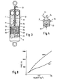
- Figure 3 is a cross section through a shock absorber forming part of the suspension system shown in Figure 2;
- Figure 4 is a cross section through a valve member forming part of the shock absorber shown in Figure 3;
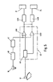
- Figure 5 is a block diagram of a control system forming part of the suspension system shown on Figure 2 according to a first embodiment of the invention;
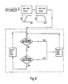
- Figure 6 is a flow chart of the control program for the control system according to the first embodiment of the invention;
- Figure 7 is a flow chart of the control program for the conrol system according to a first modification of the first embodiment of the invention;
- Figure 8 is a graph showing typical characteristics of the shock absorber shown in Figure 3 when set to a stiff or soft setting;
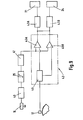
- Figure 9 is a block diagram of a control system forming part of the suspension system shown in Figures 2 to 4 according to a second embodiment of the invention;
- Figure 10 is a flow chart of the control program for the control system according to the second embodiment of the invention;
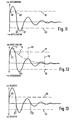
- Figure 11 is a graph of sprung mass vertical acceleration against time for the suspension system shown in Figures 2 to 6 showing the switching points;
- Figure 12 is a graph of sprung mass vertical acceleration against time for the suspension system shown in Figures 2 to 5 and 7 showing the switching points;
- Figure 13 is a graph of sprung mass vertical velocity against time for the suspension system shown in Figures 2 to 4 and 9 to 10 according to the second embodiment of the invention showing the switching points.
- Figure 1 is a schematic diagram of a conventional suspension system as described above in which a spring 1 and damper 2 connect a sprung mass 3 and an unsprung mass 4. A spring 5 is also shown to represent the spring provided by the tyre between the ground and the unsprung mass 4.
- The suspension system according to the first embodiment of the invention seeks to compromise between the requirement to provide low damping, to prevent the transmission of vibration at 'wheel-hop', and the requirement to provide high damping to prevent 'float' at primary ride frequency.
- With reference to Figures 2 to 6, 8 and 11 there is shown a motor vehicle having a body 13, a number of road wheels 15 and a suspension system to provide a damped resilient connection between the wheels 15 and the body 13 forming a sprung mass.
- The suspension system comprises a number of dampers or shock absorbers 12, a number of road springs (not shown) an accelerometer 16 connected to the body 13, a microprocessor based control system 18, and a vehicle forward speed transducer 17.
- Each of the shock absorbers 12 has a casing 26 in which is slidably supported a piston 25 adapted for connection to part of the body 13 of the vehicle by means of a tubular rod 22.
- The piston 25 includes a number of bypass passages 28 and first and second solenoid valves 21, 24. The first solenoid valve 21 closes when energised to increase the stiffness of the shock absorber in the bump directon of travel and the second solenoid valve 24 closes when energised to increase the stiffness of the shock absorber in the rebound direction of travel.
- The first and second solenoid valves 21 and 24 are connected to the control system 18 by means of a multi-cored wire 23 which passes along the bore of the tubular rod 22.
- The principle of operation of the two solenoid valves can be best understood with reference to figure 4 of the drawings. As the shock absorber is compressed the fluid 7 is forced into the valve 21 through the bleed orifice 32 which is partially obstructed by a sphere 33. The sphere 33 is urged towards the orifice 32 by the solenoid 34, when energised in response to a signal from the control system 18, to close off the orifice 32.
- The position that the sphere 33 adopts therefore determines the damping effect of the shock absorber 12, if the orifice 32 is closed off by the sphere 33 then fluid 7 can only be transferred from one side of the piston 25 to the other through the bypass passages 28 thereby greatly increasing the damping effect of the shock absorber. If the solenoid is not energised then the sphere 33 is moved back by the flow of the fluid 7 through the orifice 32 and the restriction to flow is that primarily caused by the orifice 32 itself and the damping effect is thus reduced. Flow of the fluid 7 in the other direction will cause the sphere 33 to be moved against the orifice thereby preventing flow in this direction once contact between the sphere 33 and the orifice 32 has been obtained so that the damping effect in the opposite direction of motion is not effected, each of the solenoid valves 21, 24 acting as a non-return valve.
- The other solenoid valve operates in the same manner as that previously described but being mounted in the piston 25 in the opposite sense so that it controls the flow of fluid 7 during rebound motion of the body 13.
- The piston 25 may of course be provided with conventional valves in addition to the solenoid valves mentioned to provide different damping effects in opposite directions when the solenoid valve for that direction of motion is closed. The remainder of each of the shock absorbers 12 is entirely conventional in construction and need no further description.
- The accelerometer 16, in the form of a piezoelectric accelerometer measures the vertical acceleration of the vehicle body 13, and sends a signal indicative of this movement to the control system 18 to act as the primary control parameter for the suspension system.
- The control system 18 comprises a first filter 40 to filter out frequencies below 0.3 Hz, a second filter 41 to filter out frequencies above 4.5 Hz, a central processor unit including a pre-programmed RAM unit 45A, 45B, a pre-programmed ROM unit 46 and a pair of power amplifiers 43A, 43B.
- In operation a signal from the accelerometer 16 is transmitted to the filters 40, 41 for signal conditioning. The filtered signal which represents acceleration of the body 13 only in the range of primary ride frequency is then sent to the central processor unit 42. Initially, the signal is converted into a digital signal and then is read in as the primary data for the program stored in the RAM part of the central processor 42. The program reads the data from the accelerometer 16 and compares it with predetermined threshold levels of vertical acceleration for the bump and rebound directions of motion which are stored in digital form in the ROM 46. The logical processes that occur are illustrated by the flowchart shown in Figure 6.
- With particular reference to Figure 11, if the data from the accelerometer 16 indicates that the value of vertical acceleration in the bump direction has exceeded the pre-determined threshold value X1 such as a point B1 then a control signal is sent to the amplifiers 43A, 43B by the respective RAM 45A. The signal received by the amplifiers 43A, 43B causes them to be activated and supply an energising signal to each of the solenoid valves 21, 24. The energisation of the valves 21, 24 will cause the damping of the body 13 to be increased from its normally relatively soft setting to a relatively stiff setting. The damping will stay at this relatively stiff setting until the central processor unit 42 senses that the level of acceleration in that direction has fallen below the pre- determined threshold level X1 such as at point B2 at which time the control signal to the amplifier 43A, 43B and the energising signal to the solenoid valves 21, 24 will be switched off restoring the shock absorbers 12 to their normally relatively soft setting.
- Similarly, if the data from the accelerometer 16 indicates that the value of vertical acceleration in the rebound direction has exceeded the pre- determined threshold level X2 such as at point R1 then a control signal is sent from RAM 45B to the amplifiers 43A, 43B. The signal received by the amplifier 43A, 43B causes them to be activated and supply an energising signal to each of the solenoid valves 21, 24. The energisation of the valves 21, 24 will cause the damping of the body 13 to be increased from its normally relatively soft setting to a relatively stiff setting. The damping will stay at this relatively stiff setting until the central processor unit 42 senses that the level of acceleration in that direction has fallen below the pre-determined threshold level X2 such as at point R2 at which time the control signal to the amplifiers 43A, 43B and the energising signal to the sole1'oid valves 21, 24 will be switched off restoring the shock absorbers to their normally relatively soft setting.
- As can be seen on Figure 11 the pre-determined level X1 of vertical acceleration in the bump direction is set at a higher level than the pre- determined level X2 for the rebound direction. Normally the level X1 is set at 1.5 to 3.0 times that of level X2.
- There is therefore control over the stiffness of the shock absorbers 12 in both directions of motion and the level at which switching from a relatively soft setting to a relatively stiff setting occurs is different for the bump and rebound directions.
- Figure 8 illustrates typical characteristics of the soft and stiff settings of the shock absorbers 12.
- The vehicle is thus controlled to within set limits of vertical acceleration within the limited frequency range related to the body primary ride frequency by increasing the damping only under these clearly defined conditions. The softer damping can then be used at all other times to reduce high frequency input transmission to the sprung mass.
- The electronic circuitry required to achieve these control strategies is well understood and will not therefore be described in detail.
- The system is able to respond very quickly whenever the acceleration thresholds are exceeded due to the rapid response times of the solenoid valves 21, 24 used within the shock absorbers 12. A response time of 10 msec can be achieved with this arrangement which means that the shock absorbers 12 are quite capable of being switched into and out of the stiffer setting within one cycle of the motion of the vehicle body. Besides being provided with the electromagnetically controlled valves, the shck absorbers 12 can be otherwise conventional so there is no difficulty in arranging different levels of damping to be applied in the bump and rebound directions.
- In a first modification of the first embodiment of the invention as shown in Figures 7 and 12 the suspension system is substantially as described with reference to the first embodiment, differing only in the control program and architecture of the central processor 42 as described hereafter.
- With reference to Figure 12 switching from the relatively soft setting to the relatively still setting is effected not when the pre-determined threshold level Y1 is exceeded at point F1 but at the first peak in acceleration thereafter, T1 in this case. The shock absorbers 12 will remain in their relatively stiff setting until the first peak in acceleration which does not exceed one of the pre- determined threshold level Y1, Y2 which in this case is point T1. The shock absorbers 12 will not revert to their soft setting at point Tx for this peak acceleration is greater than the pre-determined threshold level Y2 set for the rebound direction and would be the point where the shock absorbers 12 would be switched to their relatively stiff setting if point T1 did not exist.
- If the damping of the system is very high then the motion of the body 13 will decay exponentially as shown by the line TZ and not as an oscillatory exponential decay as so far described. In this case after the initial peak T1 there will be no further peaks and so the shock absorbers would remain in their relatively stiff setting indefinitely. A time delay TD is therefore provided as part of the control program, if the time delay TD is exceeded then the shock absorbers 12 are restored to their relatively soft setting.
- According to a second embodiment of the invention the acceleration signal from the accelerometer 16 is integrated to provide a signal indicative of vertical velocity of the body 13 which is then compared to pre-determined threshold levels UL, LL of velocity. If the vertical velocity of the body exceeds one of the pre-determined threshold levels UL, LL such as at point V1 then the shock absorbers 12 are switched from their relatively soft setting to their relatively stiff setting on the next occasion when the direction of motion changes, that is to say when the velocity is zero, such as at point S1. The shock absorbers 12 will remain in this relatively stiff setting until the first occasion, following a peak in velocity that does not exceed one of the levels UL, LL, when the direction of motion changes such as at point S2.
- The integration of the signal from the accelerometer 16 may be done electronically by providing an integrator unit 29 as shown on Figures 9 and 10 or it can be done mathematically as part of the control system program.
- Further improvements of the system are possible the signal from the forward speed transducer 17 for example may be used to alter the pre- determined threshold levels so that as the forward speed of the vehicle increases the threshold levels of vertical acceleration or velocity are reduced thereby taking into account the increasing dynamic effects on the vehicle.
- Alternatively, the system may be provided with shock absorbers having more than two settings. In one arrangement having three settings, the shock absorber has a third solenoid valve operable to change the damping effect in the bump direction from the relatively stiff setting to a relatively hard setting when actuated and a fourth solenoid valve operable to change the damping effect in the rebound direction from the relatively stiff setting to the relatively hard setting when actuated. A signal indicative of vehicle forward speed is supplied by the forward speed transducer 17 to the central processor 42 and is used to determine which of the settings is most appropriate. For example the shock absorbers are switched between the relatively soft setting and the relatively stiff setting at low speeds and between the relatively stiff setting and the relatively hard settings at higher speeds.
- The system may also be extended to provide individual control at each corner of the vehicle body by the provision of an accelerometer at each corner above the adjacent wheel. In this case, not only ride thresholds as described above, but also roll and pitch control with their own discrete threshold levels and frequency filtering can be provided. This can apply to roll and pitch movements induced by ride motion or those resulting from braking, acceleration or steering manoeuv- ers. In the latter cases, suitable sensors are provided in the braking, throttle and steering systems to sense movements therein and particularly the rate of change of movement.
- The relative movement between the wheel and the vehicle body may be sensed by displacement transducers, accelerometers or any other means, and the initiation of stiffer damping prevented when the wheel and body are moving in the same direction.
- As it is believed that ride comfort depends more on the rate of change in movements of the vehicle body rather than simply on the magnitude of the movements involved, this system is able to provide a marked improvement in ride quality by means of a relatively simple and inexpensive modification of a conventional suspension system.
Claims (15)
Applications Claiming Priority (2)
| Application Number | Priority Date | Filing Date | Title |
|---|---|---|---|
| GB8610842 | 1986-05-02 | ||
| GB868610842A GB8610842D0 (en) | 1986-05-02 | 1986-05-02 | Suspension system |
Publications (2)
| Publication Number | Publication Date |
|---|---|
| EP0246772A1 EP0246772A1 (en) | 1987-11-25 |
| EP0246772B1 true EP0246772B1 (en) | 1990-08-22 |
Family
ID=10597286
Family Applications (1)
| Application Number | Title | Priority Date | Filing Date |
|---|---|---|---|
| EP87303863A Expired EP0246772B1 (en) | 1986-05-02 | 1987-04-30 | A suspension system for a motor vehicle |
Country Status (4)
| Country | Link |
|---|---|
| US (1) | US4765648A (en) |
| EP (1) | EP0246772B1 (en) |
| DE (1) | DE3764399D1 (en) |
| GB (1) | GB8610842D0 (en) |
Families Citing this family (80)
| Publication number | Priority date | Publication date | Assignee | Title |
|---|---|---|---|---|
| US4869444A (en) * | 1986-09-30 | 1989-09-26 | The Boeing Company | Adjustable two-stage aircraft landing gear system |
| DE3738284A1 (en) * | 1986-12-09 | 1988-06-30 | Bosch Gmbh Robert | DEVICE FOR ACTIVE CHASSIS CONTROL IN MOTOR VEHICLES |
| GB2205285B (en) * | 1987-04-24 | 1991-05-08 | Fuji Heavy Ind Ltd | Active suspension system of vehicle |
| JPH069846Y2 (en) * | 1987-11-05 | 1994-03-16 | 三菱自動車工業株式会社 | Active suspension controller |
| DE3810638C1 (en) * | 1988-03-29 | 1989-08-10 | Boge Ag, 5208 Eitorf, De | |
| US4953089A (en) * | 1988-05-09 | 1990-08-28 | Lord Corporation | Hybrid analog digital control method and apparatus for estimation of absolute velocity in active suspension systems |
| JPH0667684B2 (en) * | 1988-06-16 | 1994-08-31 | 富士重工業株式会社 | Control device for automobile active suspension |
| JP2752668B2 (en) * | 1988-11-18 | 1998-05-18 | 株式会社ユニシアジェックス | Suspension system |
| JPH082724B2 (en) * | 1988-12-20 | 1996-01-17 | マツダ株式会社 | Vehicle suspension system |
| FR2645981B1 (en) * | 1989-04-17 | 1991-07-26 | Aerospatiale | DEVICE FOR CONTROLLING THE MOVEMENT WITHOUT VIBRATION OF AN OPTICAL ELEMENT IN A STELLAR INTERFEROMETER AND STELLAR INTERFEROMETER COMPRISING SAME |
| JP3056748B2 (en) * | 1989-05-15 | 2000-06-26 | 富士重工業株式会社 | Active suspension control system for vehicles |
| DE4017255C2 (en) * | 1989-05-29 | 1996-02-29 | Mitsubishi Electric Corp | Control device for a vehicle suspension |
| DE4042452C2 (en) * | 1989-05-29 | 1996-03-07 | Mitsubishi Electric Corp | Variable damping controller for vehicle suspension system |
| KR930009381B1 (en) * | 1989-05-29 | 1993-10-02 | 미쓰비시덴키 가부시키가이샤 | Controller for suspension stabilizer |
| DE4042453C2 (en) * | 1989-05-29 | 1996-03-07 | Mitsubishi Electric Corp | Variable damping control system for vehicle suspension |
| JP2616141B2 (en) * | 1989-05-29 | 1997-06-04 | 三菱電機株式会社 | Suspension or stabilizer control |
| DE4017421C2 (en) * | 1989-05-31 | 1994-09-15 | Mitsubishi Electric Corp | Method and device for adjusting the damping on a vehicle |
| DE3918735A1 (en) * | 1989-06-08 | 1990-12-13 | Bosch Gmbh Robert | METHOD AND DEVICE FOR DAMPING MOVEMENT PROCESSES |
| JP2605883B2 (en) * | 1989-09-04 | 1997-04-30 | 日産自動車株式会社 | Active suspension |
| EP0417702B1 (en) * | 1989-09-11 | 1997-01-08 | Toyota Jidosha Kabushiki Kaisha | Suspension control system |
| DE69018009T2 (en) * | 1989-11-02 | 1995-07-20 | Gen Motors Corp | Vehicle suspension device. |
| GB2239506B (en) * | 1989-12-08 | 1993-08-25 | Toyota Motor Co Ltd | Suspension control system |
| JPH03189218A (en) * | 1989-12-19 | 1991-08-19 | Mitsubishi Electric Corp | Suspension control device |
| DE4136224A1 (en) * | 1991-01-31 | 1992-08-06 | Fichtel & Sachs Ag | METHOD AND DEVICE FOR CONTROLLING A VIBRATION DAMPER |
| GB2279425B (en) * | 1991-01-31 | 1995-08-16 | Fichtel & Sachs Ag | Process and arrangement for controlling a vibration damper |
| US5430646A (en) * | 1991-02-22 | 1995-07-04 | Atsugi Unisia Corporation | System and method for controlling damping force coefficient of shock absorber applicable to automotive supension |
| US5235512A (en) * | 1991-06-24 | 1993-08-10 | Ford Motor Company | Self-tuning speed control for a vehicle |
| US5490068A (en) * | 1991-07-30 | 1996-02-06 | Atsugi Unisia Corporation | Suspension control system for automotive vehicle including apparatus for controlling shock absorber damping force coefficient |
| DE69212443T2 (en) * | 1991-12-06 | 1996-11-28 | Kayaba Industry Co Ltd | Suspension system |
| JP2954411B2 (en) * | 1991-12-19 | 1999-09-27 | 株式会社ユニシアジェックス | Vehicle suspension system |
| KR970011089B1 (en) * | 1992-02-14 | 1997-07-07 | 미쯔비시 지도샤 고교 가부시끼가이샤 | Road surface state determining method and suspension controlling device |
| US5255191A (en) * | 1992-03-26 | 1993-10-19 | General Motors Corporation | Vehicle suspension control with relative suspension position sensor and differentiator |
| JPH06143968A (en) * | 1992-10-30 | 1994-05-24 | Mitsubishi Motors Corp | Suspension control device |
| DE4240614A1 (en) * | 1992-12-03 | 1994-06-09 | Bosch Gmbh Robert | System for regulating and / or controlling an adjustable and / or controllable undercarriage |
| US5483448A (en) * | 1992-12-14 | 1996-01-09 | Ford Motor Company | Adaptive vehicle suspension system with mechanism for varying controller gains in response to changing road roughness conditions |
| US5363300A (en) * | 1993-02-01 | 1994-11-08 | General Motors Corporation | Vehicle acceleration sensor |
| GB9321056D0 (en) * | 1993-10-08 | 1993-12-01 | Acg France | Vehicle damping system |
| DE4430931A1 (en) * | 1994-08-31 | 1996-03-07 | Blaupunkt Werke Gmbh | Device for controlling the volume of a car radio based on driving noise |
| US5955855A (en) * | 1997-04-09 | 1999-09-21 | Medar, Inc. | Method and system for tuning a drive to its coupled motor to minimize motor resonance and sensing device for use therein |
| JP4200404B2 (en) * | 1999-03-31 | 2008-12-24 | 株式会社日立製作所 | Suspension control device |
| US6637561B1 (en) * | 1999-11-11 | 2003-10-28 | Raytheon Company | Vehicle suspension system |
| US6418856B2 (en) | 1999-11-11 | 2002-07-16 | Raytheon Company | Passive steering assembly for a guided vehicle |
| US6298791B1 (en) | 1999-11-11 | 2001-10-09 | Raytheon Company | Lateral suspension assembly for a guided vehicle system |
| US6308636B1 (en) | 1999-11-11 | 2001-10-30 | Raytheon Company | In-vehicle switch mechanism |
| US20040258254A1 (en) | 2003-06-17 | 2004-12-23 | Mollon Eric L. | Automotive audio system adapted to roadway conditions |
| US7364003B2 (en) * | 2005-02-25 | 2008-04-29 | Caterpillar Inc. | Systems and methods for the mitigation of hop |
| JP2009137545A (en) * | 2007-12-10 | 2009-06-25 | Toyota Motor Corp | Damping force control device |
| US10047817B2 (en) | 2009-01-07 | 2018-08-14 | Fox Factory, Inc. | Method and apparatus for an adjustable damper |
| US9452654B2 (en) | 2009-01-07 | 2016-09-27 | Fox Factory, Inc. | Method and apparatus for an adjustable damper |
| US8627932B2 (en) | 2009-01-07 | 2014-01-14 | Fox Factory, Inc. | Bypass for a suspension damper |
| US11306798B2 (en) | 2008-05-09 | 2022-04-19 | Fox Factory, Inc. | Position sensitive suspension damping with an active valve |
| US9033122B2 (en) | 2009-01-07 | 2015-05-19 | Fox Factory, Inc. | Method and apparatus for an adjustable damper |
| US10060499B2 (en) | 2009-01-07 | 2018-08-28 | Fox Factory, Inc. | Method and apparatus for an adjustable damper |
| US20100170760A1 (en) | 2009-01-07 | 2010-07-08 | John Marking | Remotely Operated Bypass for a Suspension Damper |
| US8857580B2 (en) | 2009-01-07 | 2014-10-14 | Fox Factory, Inc. | Remotely operated bypass for a suspension damper |
| US8393446B2 (en) | 2008-08-25 | 2013-03-12 | David M Haugen | Methods and apparatus for suspension lock out and signal generation |
| US9422018B2 (en) | 2008-11-25 | 2016-08-23 | Fox Factory, Inc. | Seat post |
| US9140325B2 (en) | 2009-03-19 | 2015-09-22 | Fox Factory, Inc. | Methods and apparatus for selective spring pre-load adjustment |
| US10036443B2 (en) | 2009-03-19 | 2018-07-31 | Fox Factory, Inc. | Methods and apparatus for suspension adjustment |
| US9556925B2 (en) | 2009-01-07 | 2017-01-31 | Fox Factory, Inc. | Suspension damper with by-pass valves |
| US10821795B2 (en) | 2009-01-07 | 2020-11-03 | Fox Factory, Inc. | Method and apparatus for an adjustable damper |
| US11299233B2 (en) | 2009-01-07 | 2022-04-12 | Fox Factory, Inc. | Method and apparatus for an adjustable damper |
| US9038791B2 (en) | 2009-01-07 | 2015-05-26 | Fox Factory, Inc. | Compression isolator for a suspension damper |
| US8936139B2 (en) | 2009-03-19 | 2015-01-20 | Fox Factory, Inc. | Methods and apparatus for suspension adjustment |
| DK177094B1 (en) | 2009-09-15 | 2011-08-22 | Ecomove Aps | A transport means and a vehicle |
| US8672106B2 (en) | 2009-10-13 | 2014-03-18 | Fox Factory, Inc. | Self-regulating suspension |
| EP2312180B1 (en) | 2009-10-13 | 2019-09-18 | Fox Factory, Inc. | Apparatus for controlling a fluid damper |
| US10697514B2 (en) | 2010-01-20 | 2020-06-30 | Fox Factory, Inc. | Remotely operated bypass for a suspension damper |
| DE102010015425A1 (en) * | 2010-04-19 | 2011-10-20 | Audi Ag | Device for operating a drive unit of a motor vehicle |
| EP2402239B1 (en) | 2010-07-02 | 2020-09-02 | Fox Factory, Inc. | Adjustable seat post |
| EP3636953B1 (en) | 2011-05-31 | 2023-09-27 | Fox Factory, Inc. | Apparatus for position sensitive and/or adjustable suspension damping |
| EP2567839B1 (en) | 2011-09-12 | 2019-03-13 | Fox Factory, Inc. | Methods and apparatus for suspension set up |
| US11279199B2 (en) | 2012-01-25 | 2022-03-22 | Fox Factory, Inc. | Suspension damper with by-pass valves |
| US10330171B2 (en) | 2012-05-10 | 2019-06-25 | Fox Factory, Inc. | Method and apparatus for an adjustable damper |
| US10737546B2 (en) | 2016-04-08 | 2020-08-11 | Fox Factory, Inc. | Electronic compression and rebound control |
| JP6478063B2 (en) * | 2016-05-13 | 2019-03-06 | トヨタ自動車株式会社 | Damping force control device for vehicle |
| WO2018187580A1 (en) * | 2017-04-05 | 2018-10-11 | ClearMotion, Inc. | Active force cancellation at structural interfaces |
| US11117781B2 (en) * | 2018-05-02 | 2021-09-14 | Otis Elevator Company | Vertical bounce detection and mitigation |
| US20230271594A1 (en) * | 2020-07-10 | 2023-08-31 | ClearMotion, Inc. | Integrated vehicle braking system |
| US20220266939A1 (en) * | 2021-02-23 | 2022-08-25 | Fox Factory, Inc. | Orientationally flexible bump sensor |
Family Cites Families (13)
| Publication number | Priority date | Publication date | Assignee | Title |
|---|---|---|---|---|
| US3124368A (en) * | 1964-03-10 | Electronic controlled vehicle suspension system | ||
| US3861696A (en) * | 1972-06-01 | 1975-01-21 | Bofors Ab | Device for damping rocking movements occurring in a chassis |
| DE2943486C2 (en) * | 1979-10-27 | 1986-07-17 | Messerschmitt-Boelkow-Blohm Gmbh, 8012 Ottobrunn | Device for shock and vibration damping for vehicles |
| GB2068308B (en) * | 1980-01-23 | 1983-09-14 | Lucas Industries Ltd | Control system for vehicle hydraulic suspension |
| JPS58112819A (en) * | 1981-12-28 | 1983-07-05 | Nippon Denso Co Ltd | Method of controlling shock absorbers |
| JPS59120509A (en) * | 1982-12-27 | 1984-07-12 | Toyota Motor Corp | Damping force control device of shock absorber in suspension mechanism of car |
| JPS6069711U (en) * | 1983-10-20 | 1985-05-17 | トキコ株式会社 | Damping force adjustable hydraulic shock absorber |
| US4770438A (en) * | 1984-01-20 | 1988-09-13 | Nissan Motor Co., Ltd. | Automotive suspension control system with road-condition-dependent damping characteristics |
| US4540188A (en) * | 1984-04-19 | 1985-09-10 | General Motors Corporation | Automatic vehicle level control |
| IT1196700B (en) * | 1984-05-11 | 1988-11-25 | Fiat Auto Spa | DEVICE FOR THE CONTROL OF THE SUSPENSION SHOCK ABSORBERS PARTICULARLY FOR CARS |
| JPS60248417A (en) * | 1984-05-21 | 1985-12-09 | Toyota Central Res & Dev Lab Inc | Active suspension apparatus |
| JPS6118513A (en) * | 1984-07-04 | 1986-01-27 | Nissan Motor Co Ltd | Suspension controller for vehicle |
| EP0205645A1 (en) * | 1985-06-26 | 1986-12-30 | Hitachi, Ltd. | Suspension control system |
-
1986
- 1986-05-02 GB GB868610842A patent/GB8610842D0/en active Pending
-
1987
- 1987-04-30 DE DE8787303863T patent/DE3764399D1/en not_active Expired - Lifetime
- 1987-04-30 EP EP87303863A patent/EP0246772B1/en not_active Expired
- 1987-04-30 US US07/044,998 patent/US4765648A/en not_active Expired - Fee Related
Also Published As
| Publication number | Publication date |
|---|---|
| EP0246772A1 (en) | 1987-11-25 |
| DE3764399D1 (en) | 1990-09-27 |
| GB8610842D0 (en) | 1986-06-11 |
| US4765648A (en) | 1988-08-23 |
Similar Documents
| Publication | Publication Date | Title |
|---|---|---|
| EP0246772B1 (en) | A suspension system for a motor vehicle | |
| US5089966A (en) | Actively controlled automotive suspension system with improved damping characteristics | |
| US5467280A (en) | Vehicular suspension system utilizing variable damping force shock absorber | |
| US4826205A (en) | Anti-squat control system for automotive suspension system | |
| EP0157181B1 (en) | Vehicular suspension control system with variable damping characteristics depending upon road condition and vehicle speed | |
| KR940010682B1 (en) | Car suspension device | |
| US5390121A (en) | Banded on-off control method for semi-active dampers | |
| CA1324646C (en) | Hybrid suspension position and body velocity sensing system for automotive suspension control system | |
| US5062658A (en) | Vehicle suspension control with real time gain switching | |
| EP1707407A1 (en) | Air suspension and electronically controlled suspension system | |
| EP0255720B1 (en) | Vehicle suspension system | |
| JPS6337725B2 (en) | ||
| JPH0662052B2 (en) | Spring mechanism for wheel suspension | |
| US5521821A (en) | Suspension control system for automotive vehicle | |
| US5979885A (en) | Damping coefficient control apparatus for damping mechanism in vehicle suspension system | |
| US4934732A (en) | Actively controller suspension system for automotive vehicle for controlling suspension characteristics with vehicular speed dependent variable damping characteristics | |
| US5526262A (en) | Automotive suspension control system utilizing variable damping force shock absorber | |
| US5802478A (en) | Automotive vehicle suspension control system | |
| US5161816A (en) | Suspension control apparatus | |
| GB2255389A (en) | Shock absorber adjustment | |
| US5555173A (en) | Damping factor switching in vehicle shock absorbers | |
| US5706196A (en) | Method and apparatus for determining the velocity of a vehicle body | |
| EP1391332A2 (en) | Semi-active damper for vehicle suspension | |
| GB2270659A (en) | System for controlling damping force characteristic of shock absorber for vehicles | |
| EP0426338B1 (en) | Vehicle suspension apparatus |
Legal Events
| Date | Code | Title | Description |
|---|---|---|---|
| PUAI | Public reference made under article 153(3) epc to a published international application that has entered the european phase |
Free format text: ORIGINAL CODE: 0009012 |
|
| AK | Designated contracting states |
Kind code of ref document: A1 Designated state(s): DE FR GB IT |
|
| 17P | Request for examination filed |
Effective date: 19880426 |
|
| 17Q | First examination report despatched |
Effective date: 19880727 |
|
| RAP1 | Party data changed (applicant data changed or rights of an application transferred) |
Owner name: ROVER GROUP LIMITED |
|
| GRAA | (expected) grant |
Free format text: ORIGINAL CODE: 0009210 |
|
| AK | Designated contracting states |
Kind code of ref document: B1 Designated state(s): DE FR GB IT |
|
| REF | Corresponds to: |
Ref document number: 3764399 Country of ref document: DE Date of ref document: 19900927 |
|
| ET | Fr: translation filed | ||
| ITF | It: translation for a ep patent filed |
Owner name: ING. C. GREGORJ S.P.A. |
|
| REG | Reference to a national code |
Ref country code: GB Ref legal event code: 732 |
|
| ITTA | It: last paid annual fee | ||
| PLBE | No opposition filed within time limit |
Free format text: ORIGINAL CODE: 0009261 |
|
| STAA | Information on the status of an ep patent application or granted ep patent |
Free format text: STATUS: NO OPPOSITION FILED WITHIN TIME LIMIT |
|
| 26N | No opposition filed | ||
| PGFP | Annual fee paid to national office [announced via postgrant information from national office to epo] |
Ref country code: DE Payment date: 19950629 Year of fee payment: 9 |
|
| PG25 | Lapsed in a contracting state [announced via postgrant information from national office to epo] |
Ref country code: DE Effective date: 19970101 |
|
| REG | Reference to a national code |
Ref country code: FR Ref legal event code: CA |
|
| PGFP | Annual fee paid to national office [announced via postgrant information from national office to epo] |
Ref country code: FR Payment date: 19980312 Year of fee payment: 12 |
|
| PGFP | Annual fee paid to national office [announced via postgrant information from national office to epo] |
Ref country code: GB Payment date: 19980320 Year of fee payment: 12 |
|
| PG25 | Lapsed in a contracting state [announced via postgrant information from national office to epo] |
Ref country code: GB Free format text: LAPSE BECAUSE OF NON-PAYMENT OF DUE FEES Effective date: 19990430 |
|
| GBPC | Gb: european patent ceased through non-payment of renewal fee |
Effective date: 19990430 |
|
| PG25 | Lapsed in a contracting state [announced via postgrant information from national office to epo] |
Ref country code: FR Free format text: LAPSE BECAUSE OF NON-PAYMENT OF DUE FEES Effective date: 19991231 |
|
| REG | Reference to a national code |
Ref country code: FR Ref legal event code: ST |
|
| PG25 | Lapsed in a contracting state [announced via postgrant information from national office to epo] |
Ref country code: IT Free format text: LAPSE BECAUSE OF NON-PAYMENT OF DUE FEES;WARNING: LAPSES OF ITALIAN PATENTS WITH EFFECTIVE DATE BEFORE 2007 MAY HAVE OCCURRED AT ANY TIME BEFORE 2007. THE CORRECT EFFECTIVE DATE MAY BE DIFFERENT FROM THE ONE RECORDED. Effective date: 20050430 |