CN108780316B - Method and system for movement control of a flying device - Google Patents
Method and system for movement control of a flying device Download PDFInfo
- Publication number
- CN108780316B CN108780316B CN201680082603.8A CN201680082603A CN108780316B CN 108780316 B CN108780316 B CN 108780316B CN 201680082603 A CN201680082603 A CN 201680082603A CN 108780316 B CN108780316 B CN 108780316B
- Authority
- CN
- China
- Prior art keywords
- coordinate system
- movable object
- axis
- perspective
- signal
- Prior art date
- Legal status (The legal status is an assumption and is not a legal conclusion. Google has not performed a legal analysis and makes no representation as to the accuracy of the status listed.)
- Expired - Fee Related
Links
- 238000000034 method Methods 0.000 title claims abstract description 103
- 230000033001 locomotion Effects 0.000 title claims description 188
- 230000008447 perception Effects 0.000 claims description 77
- 238000004891 communication Methods 0.000 claims description 39
- 230000008569 process Effects 0.000 claims description 21
- 238000005259 measurement Methods 0.000 claims description 12
- 230000001131 transforming effect Effects 0.000 claims 2
- 238000003384 imaging method Methods 0.000 description 50
- 238000006073 displacement reaction Methods 0.000 description 39
- 230000001133 acceleration Effects 0.000 description 22
- 230000008859 change Effects 0.000 description 21
- RZVHIXYEVGDQDX-UHFFFAOYSA-N 9,10-anthraquinone Chemical compound C1=CC=C2C(=O)C3=CC=CC=C3C(=O)C2=C1 RZVHIXYEVGDQDX-UHFFFAOYSA-N 0.000 description 11
- 238000012545 processing Methods 0.000 description 11
- 239000011159 matrix material Substances 0.000 description 10
- 230000003287 optical effect Effects 0.000 description 9
- 238000013016 damping Methods 0.000 description 7
- 238000006243 chemical reaction Methods 0.000 description 6
- 238000003860 storage Methods 0.000 description 6
- 230000009466 transformation Effects 0.000 description 6
- 230000000694 effects Effects 0.000 description 5
- 239000000463 material Substances 0.000 description 5
- 230000002452 interceptive effect Effects 0.000 description 4
- 230000007246 mechanism Effects 0.000 description 4
- 230000001953 sensory effect Effects 0.000 description 4
- 230000001413 cellular effect Effects 0.000 description 3
- 230000024703 flight behavior Effects 0.000 description 3
- 238000003331 infrared imaging Methods 0.000 description 3
- 238000012986 modification Methods 0.000 description 3
- 230000004048 modification Effects 0.000 description 3
- 238000013519 translation Methods 0.000 description 3
- 238000007792 addition Methods 0.000 description 2
- 238000013459 approach Methods 0.000 description 2
- 230000000712 assembly Effects 0.000 description 2
- 238000000429 assembly Methods 0.000 description 2
- 230000005540 biological transmission Effects 0.000 description 2
- 230000006870 function Effects 0.000 description 2
- 230000007935 neutral effect Effects 0.000 description 2
- 238000006467 substitution reaction Methods 0.000 description 2
- 230000000007 visual effect Effects 0.000 description 2
- 244000025254 Cannabis sativa Species 0.000 description 1
- 239000006096 absorbing agent Substances 0.000 description 1
- 230000009471 action Effects 0.000 description 1
- 230000006978 adaptation Effects 0.000 description 1
- 239000000853 adhesive Substances 0.000 description 1
- 230000001070 adhesive effect Effects 0.000 description 1
- 230000008901 benefit Effects 0.000 description 1
- 238000002485 combustion reaction Methods 0.000 description 1
- 238000004883 computer application Methods 0.000 description 1
- 230000007123 defense Effects 0.000 description 1
- 238000013461 design Methods 0.000 description 1
- 230000002708 enhancing effect Effects 0.000 description 1
- 238000001914 filtration Methods 0.000 description 1
- 239000006260 foam Substances 0.000 description 1
- 239000007789 gas Substances 0.000 description 1
- 239000007788 liquid Substances 0.000 description 1
- 230000003137 locomotive effect Effects 0.000 description 1
- 238000012423 maintenance Methods 0.000 description 1
- 238000004519 manufacturing process Methods 0.000 description 1
- 230000000116 mitigating effect Effects 0.000 description 1
- 239000000203 mixture Substances 0.000 description 1
- 230000004044 response Effects 0.000 description 1
- 230000035939 shock Effects 0.000 description 1
- 238000004904 shortening Methods 0.000 description 1
- 239000007787 solid Substances 0.000 description 1
- 230000007704 transition Effects 0.000 description 1
- 238000002604 ultrasonography Methods 0.000 description 1
- 239000013598 vector Substances 0.000 description 1
- XLYOFNOQVPJJNP-UHFFFAOYSA-N water Substances O XLYOFNOQVPJJNP-UHFFFAOYSA-N 0.000 description 1
Images


Classifications
-
- B—PERFORMING OPERATIONS; TRANSPORTING
- B64—AIRCRAFT; AVIATION; COSMONAUTICS
- B64D—EQUIPMENT FOR FITTING IN OR TO AIRCRAFT; FLIGHT SUITS; PARACHUTES; ARRANGEMENTS OR MOUNTING OF POWER PLANTS OR PROPULSION TRANSMISSIONS IN AIRCRAFT
- B64D47/00—Equipment not otherwise provided for
- B64D47/08—Arrangements of cameras
-
- G—PHYSICS
- G05—CONTROLLING; REGULATING
- G05D—SYSTEMS FOR CONTROLLING OR REGULATING NON-ELECTRIC VARIABLES
- G05D1/00—Control of position, course or altitude of land, water, air, or space vehicles, e.g. automatic pilot
- G05D1/08—Control of attitude, i.e. control of roll, pitch, or yaw
- G05D1/0808—Control of attitude, i.e. control of roll, pitch, or yaw specially adapted for aircraft
-
- B—PERFORMING OPERATIONS; TRANSPORTING
- B64—AIRCRAFT; AVIATION; COSMONAUTICS
- B64C—AEROPLANES; HELICOPTERS
- B64C39/00—Aircraft not otherwise provided for
- B64C39/02—Aircraft not otherwise provided for characterised by special use
- B64C39/024—Aircraft not otherwise provided for characterised by special use of the remote controlled vehicle type, i.e. RPV
-
- G—PHYSICS
- G03—PHOTOGRAPHY; CINEMATOGRAPHY; ANALOGOUS TECHNIQUES USING WAVES OTHER THAN OPTICAL WAVES; ELECTROGRAPHY; HOLOGRAPHY
- G03B—APPARATUS OR ARRANGEMENTS FOR TAKING PHOTOGRAPHS OR FOR PROJECTING OR VIEWING THEM; APPARATUS OR ARRANGEMENTS EMPLOYING ANALOGOUS TECHNIQUES USING WAVES OTHER THAN OPTICAL WAVES; ACCESSORIES THEREFOR
- G03B15/00—Special procedures for taking photographs; Apparatus therefor
- G03B15/006—Apparatus mounted on flying objects
-
- G—PHYSICS
- G05—CONTROLLING; REGULATING
- G05D—SYSTEMS FOR CONTROLLING OR REGULATING NON-ELECTRIC VARIABLES
- G05D1/00—Control of position, course or altitude of land, water, air, or space vehicles, e.g. automatic pilot
- G05D1/0094—Control of position, course or altitude of land, water, air, or space vehicles, e.g. automatic pilot involving pointing a payload, e.g. camera, weapon, sensor, towards a fixed or moving target
-
- G—PHYSICS
- G05—CONTROLLING; REGULATING
- G05D—SYSTEMS FOR CONTROLLING OR REGULATING NON-ELECTRIC VARIABLES
- G05D1/00—Control of position, course or altitude of land, water, air, or space vehicles, e.g. automatic pilot
- G05D1/10—Simultaneous control of position or course in three dimensions
- G05D1/101—Simultaneous control of position or course in three dimensions specially adapted for aircraft
-
- B—PERFORMING OPERATIONS; TRANSPORTING
- B64—AIRCRAFT; AVIATION; COSMONAUTICS
- B64U—UNMANNED AERIAL VEHICLES [UAV]; EQUIPMENT THEREFOR
- B64U10/00—Type of UAV
- B64U10/10—Rotorcrafts
-
- B—PERFORMING OPERATIONS; TRANSPORTING
- B64—AIRCRAFT; AVIATION; COSMONAUTICS
- B64U—UNMANNED AERIAL VEHICLES [UAV]; EQUIPMENT THEREFOR
- B64U10/00—Type of UAV
- B64U10/10—Rotorcrafts
- B64U10/13—Flying platforms
-
- B—PERFORMING OPERATIONS; TRANSPORTING
- B64—AIRCRAFT; AVIATION; COSMONAUTICS
- B64U—UNMANNED AERIAL VEHICLES [UAV]; EQUIPMENT THEREFOR
- B64U10/00—Type of UAV
- B64U10/10—Rotorcrafts
- B64U10/13—Flying platforms
- B64U10/14—Flying platforms with four distinct rotor axes, e.g. quadcopters
-
- B—PERFORMING OPERATIONS; TRANSPORTING
- B64—AIRCRAFT; AVIATION; COSMONAUTICS
- B64U—UNMANNED AERIAL VEHICLES [UAV]; EQUIPMENT THEREFOR
- B64U2101/00—UAVs specially adapted for particular uses or applications
- B64U2101/30—UAVs specially adapted for particular uses or applications for imaging, photography or videography
-
- B—PERFORMING OPERATIONS; TRANSPORTING
- B64—AIRCRAFT; AVIATION; COSMONAUTICS
- B64U—UNMANNED AERIAL VEHICLES [UAV]; EQUIPMENT THEREFOR
- B64U2101/00—UAVs specially adapted for particular uses or applications
- B64U2101/60—UAVs specially adapted for particular uses or applications for transporting passengers; for transporting goods other than weapons
-
- B—PERFORMING OPERATIONS; TRANSPORTING
- B64—AIRCRAFT; AVIATION; COSMONAUTICS
- B64U—UNMANNED AERIAL VEHICLES [UAV]; EQUIPMENT THEREFOR
- B64U2201/00—UAVs characterised by their flight controls
- B64U2201/20—Remote controls
Abstract
A method of controlling a movable object having a first perspective is disclosed. The method may include: receiving an input signal emanating from a second perspective; and converting the input signal from the second perspective to the first perspective. The method may further include moving the movable object based on the converted signal.
Description
Copyright notice
A portion of the disclosure of this patent document contains material which is subject to copyright protection. The copyright owner has no objection to the facsimile reproduction by anyone of the patent document or the patent disclosure, as it appears in the patent and trademark office patent file or records, but otherwise reserves all copyright rights whatsoever.
Technical Field
The present disclosure relates generally to device movement control, and more particularly to methods and systems for movement control of flying devices.
Background
Unmanned aerial vehicles ("UAVs") (sometimes referred to as "drones") include drones of various sizes and configurations that can be remotely operated by a user and/or programmed for automatic flight. UAVs can be used for a variety of purposes and are often used in a variety of personal, commercial, and tactical applications. In many applications, UAVs may also be equipped with auxiliary devices to perform various tasks. For example, drones equipped with imaging equipment (e.g., cameras, video cameras, etc.) may capture images or video clips that are difficult, impractical, or not possible to capture at all. UAVs equipped with imaging devices are particularly useful in surveillance, defense, and professional video industries, and are also popular with fans for entertainment.
Image quality can be affected by multiple aspects of UAV flight control and it is difficult to control the movement of the UAV while simultaneously operating imaging equipment attached to the UAV. For example, it is difficult to efficiently operate imaging equipment attached to a UAV while also accurately controlling the UAV's distance from an object or target, the UAV's multi-axis spatial orientation, and the UAV's flight stability, which can affect image quality. Controlling both the UAV and attached imaging equipment can be more challenging when the target is in motion or during complex flight maneuvers during which the user's spatial reference frame is different from that of the UAV control system.
Disclosure of Invention
In one aspect, the present disclosure is directed to a method of controlling a movable object having a first perspective. The method may include: receiving an input signal from a second perspective; converting the input signal from the second perspective to the first perspective; causing movement of the movable object based on the converted signal.
In another aspect, the present disclosure is directed to a system for controlling a movable object having a first perspective. The system may include a controller having one or more processors. The controller may be configured to: receiving an input signal from a second perspective; converting the input signal from the second perspective to the first perspective; and causing movement of the movable object based on the converted signal.
In yet another aspect, the present disclosure is directed to an Unmanned Aerial Vehicle (UAV) system having a first perspective. The UAV system may include one or more propulsion devices and a controller in communication with the one or more propulsion devices. The controller may be configured to control the UAV to track a target object, the controller comprising: one or more processors configured to receive an input signal emanating from a second perspective; converting the input signal from the second perspective to the first perspective; and generating one or more signals to control the one or more propulsion devices and causing movement of the UAV based on the converted signals.
In yet another aspect, the present disclosure relates to a non-transitory computer-readable medium storing instructions that, when executed, cause a computer to perform a method of controlling a movable object having a first perspective, wherein the method may include: receiving an input signal from a second perspective; converting the input signal from the second perspective to the first perspective; causing movement of the movable object based on the converted signal.
In yet another aspect, the present disclosure is directed to a method for controlling a movable object having a first coordinate system. The method may include: determining an offset between the first coordinate system and the second coordinate system; receiving user input indicative of a desired movement of the movable object in a second coordinate system; and generating a control signal in the first coordinate system based on the user input and an offset between the first coordinate system and the second coordinate system, wherein the control signal is configured to: causing the movable object to move in a first coordinate system in accordance with the control signal, and the movement in the first coordinate system corresponds to a desired movement in a second coordinate system.
In yet another aspect, the present disclosure is directed to a system for controlling a movable object having a first coordinate system. The system may include a controller having one or more processors and configured to: determining an offset between the first coordinate system and the second coordinate system; receiving user input indicative of a desired movement of the movable object in a second coordinate system; generating a control signal in the first coordinate system based on the user input and an offset between the first coordinate system and the second coordinate system, wherein the control signal is configured to: the movable object is caused to move in the first coordinate system in accordance with the control signal, and the movement in the first coordinate system corresponds to a desired movement in the second coordinate system.
In yet another aspect, the present disclosure is directed to an Unmanned Aerial Vehicle (UAV) system having a first perspective. The UAV system may include one or more propulsion devices and a controller in communication with the one or more propulsion devices. The controller may be configured to control the UAV to track a target object, the controller including one or more processors configured to: determining an offset between the first coordinate system and the second coordinate system; receiving user input indicative of a desired movement of the movable object in a second coordinate system; and generating a control signal in the first coordinate system based on the user input and a difference between the first coordinate system and the second coordinate system, wherein the control signal is configured to control the one or more propulsion devices and cause the movable object to make a movement in the first coordinate system corresponding to the desired movement in the second coordinate system.
In yet another aspect, the present disclosure relates to a non-transitory computer-readable medium storing instructions that, when executed, cause a computer to perform a method for controlling a movable object having a first coordinate system, wherein the method comprises: determining an offset between the first coordinate system and the second coordinate system; receiving user input indicative of a desired movement of the movable object in a second coordinate system; and generating a control signal in the first coordinate system based on the user input and an offset between the first coordinate system and the second coordinate system, wherein the control signal is configured to: the movable object is caused to move in the first coordinate system in accordance with the control signal, and the movement in the first coordinate system corresponds to a desired movement in the second coordinate system.
In yet another aspect, the present disclosure is directed to a method for controlling a movable object. The method may include: receiving a user input indicating a command to adjust perception of a target while tracking the target; determining a subsequent perception of the target based on the user input; and generating one or more control signals for moving the movable object based on the subsequent perception of the target.
In yet another aspect, the present disclosure is directed to a system for controlling a movable object. The system may include a controller having one or more processors configured to: receiving a user input indicating a command to adjust perception of a target while tracking the target; determining a subsequent perception of the target based on the user input; and generating one or more control signals for moving the movable object based on the subsequent perception of the target.
In yet another aspect, the present disclosure is directed to an Unmanned Aerial Vehicle (UAV) system having a first perspective. The UAV system may include one or more propulsion devices and a controller in communication with the one or more propulsion devices and configured to control the UAV to track a target object, the controller including one or more processors configured to: receiving a user input indicating a command to adjust perception of a target while tracking the target; determining a subsequent perception of the target based on the user input; and generating one or more signals for moving the movable object based on the subsequent perception of the target.
In yet another aspect, the present disclosure relates to a non-transitory computer-readable medium storing instructions that, when executed, cause a computer to perform a method for controlling a movable object, wherein the method comprises: receiving a user input indicating a command to adjust perception of a target while tracking the target; determining a subsequent perception of the target based on the user input; and generating one or more control signals for moving the movable object based on the subsequent perception of the target.
Drawings
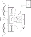
FIG. 1 illustrates a movable object with a carrier and a ballast and a control terminal according to the present disclosure;
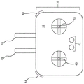
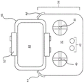
fig. 2A and 2B illustrate a control terminal that may be used with embodiments in accordance with the present disclosure;
FIG. 3 illustrates a controller that may be used with embodiments of the present disclosure;
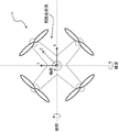
4A-4B illustrate coordinate systems that may be used with embodiments in accordance with the present disclosure;
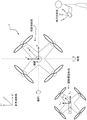
fig. 5A-5C illustrate a movable object with a cargo in accordance with an embodiment of the present disclosure;
6A-6C illustrate a movable object having a carrier and a carry object in accordance with an embodiment of the present disclosure;
FIG. 7 illustrates operation of a movable object according to the present disclosure;
FIG. 8 illustrates a coordinate system that may be used with embodiments of the present disclosure;
FIGS. 9A and 9B illustrate a movable object, a control terminal, and a coordinate system according to an embodiment of the disclosure;
FIG. 10 illustrates a system for controlling a movable object according to the present disclosure;
FIG. 11 illustrates a system for controlling a movable object according to the present disclosure;
FIG. 12 illustrates a system for controlling a movable object according to the present disclosure;
FIG. 13 illustrates a system for controlling a movable object while tracking a target according to the present disclosure;
14A and 14B illustrate a system for controlling a movable object while tracking a target according to the present disclosure;
15A and 15B illustrate a system for controlling a movable object while tracking a target according to the present disclosure; and
16-22 illustrate a system for controlling a movable object while tracking a target according to the present disclosure.
Detailed Description
The following detailed description refers to the accompanying drawings. Wherever possible, the same reference numbers will be used throughout the drawings and the following description to refer to the same or like parts. While several illustrative embodiments have been described herein, modifications, adaptations, and other implementations are possible. For example, substitutions, additions or modifications may be made to the components illustrated in the drawings, and the illustrative methods described herein may be modified by performing the substitution, reordering, removal or addition steps to the disclosed methods. The following detailed description is, therefore, not to be limited to the disclosed embodiments and examples. Rather, the appropriate scope is defined by the appended claims.
In many industries and in many cases, Unmanned Aerial Vehicles (UAVs) are considered useful tools for mitigating responsible personnel who directly perform certain tasks. For example, drones have been used to deliver goods, perform surveillance, and collect various types of imaging and sensory data (e.g., photographs, video, ultrasound, infrared, etc.) in professional and recreational settings, providing great flexibility and enhancing the ability of people.
Although UAVs may be "unmanned" (i.e., operated without onboard personnel), UAVs are typically operated in whole or in part by off-board personnel who may be responsible for controlling aspects of flight and/or other associated tasks (e.g., controlling cargo, operating imaging equipment, etc.). In many cases, the associated tasks (e.g., operating imaging equipment mounted on a UAV) must be performed concurrently with flight control, which can be challenging.
For example, in professional photography, cinematography, and videography, UAVs may be used to capture segments from fixed and/or mobile perspectives that may be too challenging, impractical, or impossible for a person to capture. In this case, however, the convenience of the UAV does not eliminate the need for the UAV operator to carefully control the imaging equipment to achieve high quality results. Furthermore, using imaging equipment on the UAV requires skilled control of UAV flight parameters, as inconsistent or unstable flight (e.g., when flight parameters (e.g., roll, pitch, yaw, altitude, throttle, relative position or velocity with respect to a target, etc.) are made to fluctuate or vary considerably or are otherwise poorly controlled) can degrade image quality.
As with many types of UAVs, an operator may control multiple flight parameters separately via an input device (e.g., a remote control). During complex flight maneuvers and/or when collecting imaging data, it is difficult for even highly skilled UAV operators to maintain an adequate level of control over each flight parameter while attempting to obtain high quality image results. In these and other situations requiring altitude control of each flight parameter, UAV operators may wish to reduce the complexity of overall flight control. Exemplary embodiments of methods, systems, and apparatus for controlling a movable object (e.g., a UAV) are disclosed herein that may allow an operator to control the movable object relatively easily and with greater precision. In particular, embodiments described herein allow a user to operate a UAV from the perspective of the user, rather than flight parameters from the perspective of the UAV. For example, a user may simply operate a remote control to send commands for raising the UAV, as opposed to controlling the pitch angle of the UAV, and methods and systems according to the present disclosure transform such intuitive commands into flight control signals or flight parameters that may be used directly to adjust the flight behavior of the UAV.
FIG. 1 illustrates an exemplary movable object 10 that may be configured to move or travel within an environment. Movable object 10 may be any suitable object, device, mechanism, system, or machine configured to travel on or within a suitable medium (e.g., surface, air, water, track, space, subsurface, etc.). For example, the movable object 10 may be an Unmanned Aerial Vehicle (UAV). Although the movable object 10 is shown and described herein as a UAV for exemplary purposes of this description, it should be understood that other types of movable objects (e.g., wheeled objects, marine objects, locomotive objects, other airborne objects, etc.) may also or alternatively be used in embodiments according to the present disclosure. As used herein, the term UAV may refer to a flying apparatus configured to be operated and/or controlled automatically (e.g., via an electronic control system) and/or manually by off-board personnel.
The movable object 10 may include one or more (e.g., 1, 2, 3, 4, 5, 10, 15, 20, etc.) propulsion devices 12, with the propulsion devices 12 being located at different locations (e.g., top, sides, front, back, and/or bottom of the movable object 10) where the movable object 10 is propelled and guided. Propulsion device 12 may be a device or system operable to generate forces for maintaining controlled flight. The propulsion devices 12 may share or may each include or be operatively connected to a power source, such as an electric machine (e.g., an electric motor, a hydraulic motor, a pneumatic motor, etc.), an engine (e.g., an internal combustion engine, a turbine engine, etc.), a battery pack, etc., or a combination thereof. Each propulsion device 12 may also include one or more rotating assemblies 24 drivably connected to the power source and configured to participate in generating forces for maintaining controlled flight. For example, rotating assembly 24 may include rotors, propellers, blades, nozzles, etc. driven on or by: an axle, a wheel, a hydraulic system, a pneumatic system, or other component or system configured to transmit power from a power source. Propulsion devices 12 and/or rotating assembly 24 may be adjustable (e.g., tiltable) relative to each other and/or relative to movable object 10. Alternatively, propulsion device 12 and rotating assembly 24 may have a fixed orientation relative to each other and/or mobile device 10. In some embodiments, each propulsion device 12 may be of the same type. In other embodiments, propulsion device 12 may be of a variety of different types. In some embodiments, all of the propulsion devices 12 may be controlled cooperatively (e.g., all at the same speed and/or angle). In other embodiments, one or more of the propulsion devices may be independently controlled with respect to, for example, speed and/or angle.
The load 14 may include one or more sensing devices 19. The sensing device 19 may include a device for collecting or generating data or information, such as surveying, tracking, and capturing images or video of a target (e.g., an object, a landscape, a photo or video capture object, etc.)). The sensing device 19 may comprise an imaging device configured to collect data that may be used to generate an image. For example, the imaging device may include a camera, a video camera, an infrared imaging device, an ultraviolet imaging device, an X-ray device, an ultrasonic imaging device, a radar device, and the like. The sensing means 19 may also or alternatively comprise means for capturing audio data, such as a microphone or an ultrasonic detector. The sensing device 19 may also or alternatively comprise other suitable sensors for capturing visual, audio and/or electromagnetic signals.
The carrier 16 may include one or more devices configured to receive the load 14 and/or allow the load 14 to adjust (e.g., rotate) relative to the movable object 10. For example, the carrier 16 may be a pan-tilt-head (gimbal). The carrier 16 may be configured to allow the weight 14 to rotate about one or more axes, as described below. In some embodiments, the carrier 16 may be configured to allow 360 ° rotation about each axis to allow for better control of the viewing angle of the cargo 14. In other embodiments, the carrier 16 can limit the range of rotation of the carry 14 about one or more axes thereof to less than 360 (e.g., ≦ 270 °, 210 °, 180 °, 120 °, 90 °, 45 °, 30 °, 15 °, etc.).
The carrier 16 may include a frame assembly 26, one or more actuator members 28, and one or more carrier sensors 30. Frame assembly 26 may be configured to couple load 14 to moveable object 10 and, in some embodiments, allow load 14 to move relative to moveable object 10. In some embodiments, the frame assembly 26 may include one or more subframes or components that are movable relative to each other. The actuator members 28 may be configured to drive the components of the frame assembly relative to each other to provide translational and/or rotational movement of the load 14 relative to the moveable object 10. In other embodiments, the actuator member 28 may be configured to act directly on the load 14 to cause movement of the load 14 relative to the frame assembly 26 and the movable object 10. The actuator member 28 may be or include a suitable actuator and/or force transmission component. The actuator member 28 may include a motor configured to provide linear or rotational motion to the components of the frame assembly 26 and/or the load 14 along with an axle, shaft, track, belt, chain, gear, and/or other component.
The carrier sensor 30 may include a device configured to measure, sense, detect, or determine status information of the carrier 16 and/or the cargo 14. The state information may include position information (e.g., relative position, orientation, attitude, linear displacement, angular displacement, etc.), velocity information (e.g., linear velocity, angular velocity, etc.), acceleration information (e.g., linear acceleration, angular acceleration), and/or other information related to control of movement of the carrier 16 or the rider 14 relative to the movable object 10. The carrier sensor 30 may include one or more types of suitable sensors, such as potentiometers, optical sensors, visual sensors, magnetic sensors, motion or rotation sensors (e.g., gyroscopes, accelerometers, inertial sensors, etc.). The carrier sensors 30 may be associated with or attached to various components of the carrier 16 or the movable object 10 (e.g., components of the frame assembly 26, the actuator members 28) or the movable object 10. The carrier sensor 30 may be configured to communicate data and information with the controller 22 via a wired or wireless connection (e.g., RFID, bluetooth, Wi-Fi, radio, cellular, etc.). The data and information generated by the carrier sensor 30 and communicated to the controller 22 may be used by the controller 22 for further processing, such as for determining status information of the movable object 10 and/or the target.
The carrier 16 may be coupled to the movable object 10 via one or more damping elements configured to reduce or eliminate unwanted vibration or other force transmission from the movable object 10 to the load 14. The damping element may be active, passive, or hybrid (i.e., have both active and passive characteristics). The damping element may be formed of any suitable material or combination of materials including solids, liquids and gases. Compressible or deformable materials (e.g., rubber, springs, gel, foam, and/or other materials) may be used as the damping element. The damping element may serve to isolate the load 14 from the movable object 10 and/or dissipate force propagation from the movable object 10 to the load 14. The damping element may also include mechanisms or devices configured to provide a damping effect, such as pistons, springs, hydraulic devices, pneumatic devices, bumpers, shock absorbers, and/or other devices or combinations thereof.
The terminal 32 may be configured to receive an input, such as an input from a user (i.e., a user input), and transmit a signal indicative of the input to the controller 22. The terminal 32 may be configured to receive input and generate corresponding signals indicative of information for one or more types, such as control data (e.g., signals) for moving or manipulating the mobile device 10 (e.g., via the propulsion device 12), the cargo 14, and/or the carrier 16. The terminal 32 may also be configured to receive data and information from the movable object 10, such as operational data related to position data, velocity data, acceleration data, sensory data, and other data and information related to the movable object 10, its components, and/or its surroundings. The terminal 32 may be a remote control with a physical stick configured to control flight parameters, or a touch screen device (such as a smart phone or tablet) with virtual controls for the same purpose, or an application on a smart phone or tablet, or a combination thereof.
In the example shown in fig. 2A and 2B, the terminal 32 may include a communication device 34 that facilitates communication of information between the terminal 32 and other entities, such as the movable object 10. The communication device 34 may include an antenna or other device configured to transmit or receive signals. The terminal 32 may also include one or more input devices 36 configured to receive input from a user to communicate with the movable object 10. Fig. 2A shows an exemplary embodiment of a terminal 32 having a plurality of input devices 36 configured to receive user input indicative of a desired movement of the movable object 10 or a component thereof. However, it should be understood that other possible embodiments or layouts of the terminal may be possible and are within the scope of the present disclosure.
The terminal 32 may include input devices such as input wrenches 38 and 40, buttons 42, triggers 44, and/or other types of input devices for receiving one or more inputs from a user. Each input device of the terminal 32 may be configured to generate an input signal that may be communicated to the controller 22 and may be used as an input by the controller 22 for processing. In addition to flight control inputs, the terminal 32 may also be used to receive user inputs of other information, such as manual control settings, automatic control settings, control assistance settings, etc., which may be received, for example, via the buttons 42 and/or triggers 44. It should be understood that the terminal 32 may include other or additional input devices such as buttons, switches, dials, wrenches, triggers, touch pads, touch screens, soft keys, a mouse, a keyboard, and/or other types of input devices.
As shown in fig. 2B, terminal 32 may also include a display device 46 configured to display information to a user and/or receive information from a user. For example, the terminal 32 may be configured to receive a signal from the movable object 10, which may be indicative of information or data related to movement of the movable object 10 and/or data (e.g., imaging data) captured using the movable object 10 (e.g., in conjunction with the cargo 14). In some embodiments, display device 46 may be a multi-function display device configured to display information on multi-function screen 48 and to receive user input via multi-function screen 48. For example, in one embodiment, the display device 46 may be configured to receive one or more user inputs via the multi-function screen 48. In another embodiment, the multi-function screen 48 may constitute a separate input device for receiving user input.
In some embodiments, terminal 32 may be or include an interactive graphical interface for receiving one or more user inputs. That is, the terminal 32 may be a Graphical User Interface (GUI) and/or include one or more graphical versions of the input device 36 for receiving user input. The graphical version of the terminal 32 and/or the input device 36 may be displayable on a display device (e.g., display device 46) or a multi-function screen (e.g., multi-function screen 48) and include graphical features, such as interactive graphical features (e.g., graphical buttons, text boxes, drop-down menus, interactive images, etc.). For example, in one embodiment, the terminal 32 may include graphical representations of the input wrenches 38 and 40, the button 42, and the trigger 44, which may be displayed on the multifunction screen 48 and configured to receive user input via the multifunction screen 48. In some embodiments, terminal 32 may be configured to receive all user input via a graphical input device (e.g., a graphical version of input device 36). The terminal 32 may be configured to generate a graphical version of the input device 36 in conjunction with a computer application (e.g., an "app") to provide an interactive interface on a multifunction screen of a display device or any suitable electronic device for receiving user input (e.g., a cell phone, tablet, etc.).
In some embodiments, the display device 46 may be an integral component of the terminal 32. That is, the display device 46 may be attached or secured to the terminal 32. In other embodiments, the display device may be connectable to the terminal 32 (and disconnectable from the terminal 32). That is, the terminal 32 may be configured to be electrically connectable to the display device 46 (e.g., via a connection port or wireless communication link) and/or otherwise connected to the terminal 32 via the mounting device 50, such as by a clip, clasp, snap, adhesive, or other type of mounting device.
In some embodiments, terminal 32 may be configured to communicate with an electronic device that may be configured to control movement and/or other operational aspects of movable object 10. For example, the display device 46 may be a display component of an electronic device (e.g., a cellular telephone, a tablet, a personal digital assistant, a laptop computer, or other device). In this way, the user is able to incorporate the functionality of other electronic devices into controlling aspects of the movable object 10, which may allow for more flexible and adaptable control schemes to be used. For example, the terminal 32 may be configured to communicate with an electronic device having a memory and at least one processor, and then a control device of the electronic device may be used to provide user input via an input device (e.g., a multifunction display, buttons, stored app, web-based application, etc.) associated with the electronic device. The communication between the terminal 32 and the electronic device may also be configured to allow software update packages and/or other information to be received and then communicated to the controller 22 (e.g., via the communication system 20).
It should be noted that other control conventions relating input received via the terminal 32 to desired or actual movement of the mobile device 10 may be used, if desired.
As shown in fig. 3, the controller 22 may include one or more components, such as a memory 52 and at least one processor 54. The memory 52 may be or include a non-transitory computer readable medium, and may include one or more storage units of the non-transitory computer readable medium. The non-transitory computer readable medium of the memory 52 may be or include any type of disk including: floppy disks, optical disks, DVDs, CD-ROMs, microdrives, and magneto-optical disks, ROMs, RAMs, EPROMs, EEPROMs, DRAMs, VRAMs, flash memory devices, magnetic or optical cards, nanosystems (including molecular memory ICs), or any type of media or device suitable for storing instructions and/or data. The storage unit may include permanent and/or removable portions of a non-transitory computer-readable medium (e.g., a removable medium or an external storage device such as an SD card, RAM, etc.).
Information and data from sensing system 18 may be communicated to and stored in a non-transitory computer readable medium in memory 52. The non-transitory computer-readable medium associated with the memory 52 may also be configured to store logic, code, and/or program instructions executable by the processor 54 to perform any suitable embodiment of the methods described herein. For example, a non-transitory computer readable medium associated with memory 52 may be configured to store computer readable instructions that, when executed by processor 54, cause the processor to perform a method comprising one or more steps. The method performed by the processor based on instructions stored in the non-transitory computer-readable medium may involve processing various inputs, such as inputs of data or information stored in the non-transitory computer-readable medium of the memory 52, inputs received from the terminal 32, inputs received from the sensing system 18 (e.g., received directly from the sensing system or retrieved from the memory), and/or other inputs received via the communication system 20. The non-transitory computer readable medium may be configured to store sensed data from the sensing module to be processed by the processing unit. In some embodiments, a non-transitory computer readable medium may be used to store processing results produced by the processing unit.
The processor 54 may include one or more processors and may be embodied as a programmable processor (e.g., a Central Processing Unit (CPU)). The processor 54 may be operatively connected to the memory 52 or another storage device configured to store a program or instructions executable by the processor 54 for performing one or more method steps. Note that the method steps described herein may be stored in the memory 52 and configured to be executed by the processor 54 such that the method steps will be executed by the processor 54.
In some embodiments, the processor 54 may include and/or alternatively be operatively coupled to one or more control modules, such as a conversion module 56 and a tracking control module 58, which will be described in greater detail below. Conversion module 56 may be configured to control the method of converting information (e.g., inputs, commands, and other signals) from one perspective (e.g., the perspective of the user, the perspective of movable object 10, etc.) to another perspective (e.g., the user, the other perspective of the movable object, or another perspective). Tracking control module 58 may be configured to help control propulsion devices 12 of movable object 10 to adjust the spatial layout, velocity, and/or acceleration of movable object 10 with respect to six degrees of freedom (e.g., three translational directions along its coordinate axis and three rotational directions about its coordinate axis). Conversion module 56 and tracking control model 58 may be implemented in software executing on processor 54 (as shown in FIG. 6) or may be implemented in a hardware or software component (not shown) separate from processor 54.
The processor 54 may be operatively connected to the communication system 20 and configured to receive data from and/or transmit data to one or more external devices (e.g., the terminal 32, the display device 46, or other remote controls). Any suitable communication device may be used to transmit data and information to controller 22 or receive data and information from controller 22, such as via wired or wireless communication. For example, the communication system 20 may utilize one or more of a Local Area Network (LAN), a Wide Area Network (WAN), infrared, radio, WiFi, peer-to-peer (P2P) network, telecommunications network, cloud communications, and the like. Alternatively, relay stations such as towers, satellites or mobile stations may be used. The wireless communication may be proximity-related or proximity-unrelated. In some embodiments, communication may or may not require line of sight. The communication system 20 may transmit and/or receive one or more of the following: sensed data from the sensing module 18, processing results generated by the processor 54, predetermined control data, user commands from the terminal 32 or remote control, and the like.
The components of the controller 22 may be arranged in any suitable configuration. For example, one or more components of controller 22 may be located on movable object 10, carrier 16, cargo 14, terminal 32, sensing system 18, or an additional external device in communication with one or more of the above. In some embodiments, one or more processors or storage devices may be located at different locations (e.g., on movable object 10, carrier 16, mount 14, terminal 32, sensing module 18, an additional external device in communication with one or more of the above, or a suitable combination thereof) such that any suitable aspect of the processing and/or storage functions performed by the system may occur at one or more of the above locations.
The flight behavior of the movable object 10 can be understood and controlled in a defined coordinate system. For example, FIG. 4A shows a local coordinate system defined with respect to the movable object 10 for describing movement from the perspective of the movable object 10. The local coordinate system may include three axes, such as an X-axis (e.g., a first transverse axis), a Y-axis (e.g., a second transverse axis), and a Z-axis (e.g., a longitudinal axis). The movement of movable object 10 may include roll, pitch, yaw, horizontal translation (e.g., left, right, forward, backward, etc.), vertical translation (e.g., height or altitude), horizontal velocity, vertical velocity, rotational velocity (e.g., angular, radial, tangential, axial, etc.), and acceleration (e.g., horizontal, vertical, rotational, etc.). Each axis of the local coordinate system may be associated with one or more particular position or movement parameters that may be changed or adjusted during flight to facilitate efficient control of the movable object 10.
For example, in the exemplary local coordinate system of fig. 4A, each of the X, Y, and Z axes may be associated with translational and linear displacements in the direction of the respective axis and with rotational and angular displacements about the respective axis. In the example of fig. 4A, the X-axis, which may also be referred to as the pitch axis, about which the movable object 10 may undergo a pitch rotational movement (e.g., a movement that tends to tilt one of the front or rear of the movable object 10 upward and the other downward), and along which the movable object 10 may undergo a translational movement from side to side (e.g., left or right). The Y-axis may be referred to as a roll axis about which the movable object 10 may undergo roll rotational movement (i.e., movement that tends to tilt one of the left or right sides of the movable object 10 upward and the other downward), and along which the movable object 10 may undergo fore-and-aft translational movement. The Z-axis may be referred to as the yaw axis about which the movable object 10 may undergo yaw rotational movement (i.e., rotational movement in a plane defined by the X-axis and the Y-axis, or rotational movement parallel to the plane), and along which the movable object 10 may undergo up-down (i.e., vertical or longitudinal) translational movement. One of ordinary skill in the art will appreciate that more or fewer axes or different axis conventions may be used. It should also be noted that the orientation and planar descriptions (e.g., side-to-side, front-to-back, up-and-down, horizontal, vertical, etc.) are for purposes of illustration and description only and are not limiting.
Conventionally, control of the flight of the movable object 10 requires control of flight parameters, such as speed, pitch amount and direction, yaw amount and direction, etc. along a certain axis, in the local coordinate system of the movable object 10. The terminal 32 may include a control mechanism for enabling a user to control flight parameters relative to the local coordinate system.
For example, referring to fig. 2A and 2B, a first input wrench 38 on terminal 32 may be configured to receive one or more user inputs indicative of one or more aspects of controlling movement of movable object 10. Aspects of controlling the movement of the movable object 10 may include flight control aspects and load control aspects. The flight control aspects may include control of one or more aspects of the flight achievable by the movable object. For example, the flight control aspects may include a desired translational movement, a desired rotational movement, a desired velocity, and a desired acceleration of the mobile device 10. The desired translational movement may include a desired vertical or horizontal movement relative to a user's perspective, a perspective of movable object 10, a reference perspective, or a different perspective. The desired rotational movement may include a desired rotational movement of movable object 10 about one or more axes of a coordinate system associated with a viewing angle (e.g., a user's viewing angle, a viewing angle of movable object 10, a reference viewing angle, etc.) or relative to another object (e.g., a target). That is, in addition to rotating about an axis of a coordinate system associated with a perspective, a desired rotational movement may refer to movement about a reference point associated with a stationary or moving object or target.
In one embodiment, first input wrench 38 may be configured to receive one or more inputs corresponding to one or more desired translational or rotational movements of moveable object 10. For example, the first input wrench 38 may be a multi-axis control device (e.g., a joystick) configured to be displaced in a plurality of directions, each direction corresponding to a type and sign (e.g., positive, negative, forward, backward, etc.) of a command indicating a desired movement. The amount of displacement of the first input wrench 38 from the neutral position may indicate the degree or magnitude of the corresponding desired movement. For example, in one embodiment, the first input wrench 38 may be movable (e.g., tiltable) in a forward direction, a rearward direction, a left direction, and a right direction from the perspective of the user. The displacement in the forward and rearward directions may correspond to a desired movement along a first axis of a coordinate system to sense, describe or define movement of the movable apparatus 10. For example, a displacement in a forward direction may indicate a desired linear movement in a forward direction, while a displacement in a rearward direction may indicate a desired linear movement in a rearward (i.e., opposite) direction. The displacement of the first input wrench 38 in the forward direction may also or alternatively correspond to a desired rotational movement of the mobile device 10 about its pitch axis. For example, a displacement in a forward direction may indicate a desired rotational movement in a first rotational direction about the pitch axis of movable object 10, while a displacement in a rearward direction may indicate a desired rotational movement in a second (i.e., opposite) rotational direction about the pitch axis of movable object 10. The amount or degree of displacement of the first input wrench 38 in the forward or rearward direction may be indicative of a desired linear velocity or acceleration along the first axis and/or a desired rotational velocity or acceleration about the first axis. One of ordinary skill in the art will appreciate that other control conventions may be used and that the control functions may be divided among a greater or different number of input devices.
Displacement of the first input wrench 38 in the side-to-side (i.e., side-to-side) direction may correspond to a desired movement along a second axis of the coordinate system to sense, describe, or define movement of the mobile device 10. For example, a displacement in a rightward (i.e., first side) direction may indicate a desired linear movement in a rightward (i.e., first side) direction, while a displacement in a leftward direction may indicate a desired linear movement in a leftward (i.e., opposite or second side) direction. The displacement of the first input wrench 38 in the rightward and leftward directions may also or alternatively correspond to a desired rotational movement of the mobile device 10 about its roll axis. For example, a displacement in a rightward direction may indicate a desired rotational movement in a first rotational direction, while a displacement in a leftward direction may indicate a desired rotational movement in a second (i.e., opposite) rotational direction, both of which are rotations about the roll axis of the movable object 10. The amount or degree of displacement of the first input wrench 38 in the right or left direction may be indicative of a desired linear velocity or acceleration along the second axis and/or a desired rotational velocity or acceleration about the second axis.
The displacement of the second input wrench 40 in the left and right (i.e., side-to-side) directions may correspond to a desired rotational movement about a third axis of the coordinate system to sense, describe or define the movement of the mobile device 10. For example, a displacement of the second input wrench 40 in a rightward direction may indicate a desired rotational movement in a first rotational direction about the third axis, while a displacement in a leftward direction may indicate a desired rotational movement in a second (i.e., opposite) rotational direction, both of which are rotations about the yaw axis of the movable object 10. The amount or degree of displacement of the second input wrench 40 in the right or left direction may be indicative of a desired rotational speed or acceleration about the third axis.
As described above, the user requires experience and skill to control various aspects of the movement of the movable object 10, particularly during complex flight maneuvers and/or when the user must control the operation of the attached equipment (e.g., camera), not only because consideration of flight parameters such as pitch, yaw, roll may be counterintuitive, but also because the perspectives of the user and the movable object 10 are typically independent of each other and different from each other. For example, when a user views the movable object 10 in a direction that is not aligned with the X-axis of the local coordinate system of the movable object 10, the user often must either try to psychologically adapt the viewing angle of the movable object 10, or to physically move or rotate his/her body and head to align with the viewing angle of the movable object 10, in order to achieve effective control.
According to embodiments of the present disclosure, user controls may be provided, received, and interpreted from the perspective of a user, and subsequently transformed into flight control signals from the perspective of movable object 10 (e.g., its local coordinate system shown in FIG. 4A). In this way, the user can issue commands (typically intuitive commands such as turn left, turn right, go up, approach a target, move faster, etc.) at his/her own perspective, and can then translate the issued commands into commands understandable by the movable object 10 (e.g., pitch, yaw, roll, throttle, etc.). The terminal 32 may be configured to receive user input corresponding to such commands. The terminal 32 may transform or convert the user input of the user's perspective into a signal of the perspective of the movable object 10 and transmit the signal to the movable object 10. Alternatively, terminal 32 may send a user input of the user perspective to movable object 10, which movable object 10 then transforms or converts into a signal of the perspective of movable object 10 before applying the user input to the flight parameters.
In some embodiments, the terminal 32 and controller 22 may be configured to switch between a first mode in which user input received via the terminal 32 directly corresponds to movement of the movable object 10 from the perspective of the movable object 10, as described above in connection with fig. 2A-B and 4A; in the second mode, the user input received via the terminal 32 corresponds to movement of the movable object 10 from the user's perspective. For example, the terminal 32 may include a button, a switch, a knob, a touch screen icon, or some other type of input or input device configured to receive a user input indicating a user selection for entering the first mode or the second mode. The mode of operation of the wrench may also be predefined to enable switching between modes or selection of modes. Alternatively, the controller 22 may assume a default mode, such as either of the first or second modes employed upon power-up or upon receipt of an initial user input indicative of a flight command. When in the first mode, the controller 22 may be configured to receive user inputs indicative of flight parameters (e.g., roll, pitch, yaw, throttle, etc.) of the user's perspective and generate commands for the movable object 10 indicative of corresponding flight parameters of the perspective of the movable object 10 without conversion. That is, in the first mode, the user input may indicate an adjustment to a flight parameter of the movable object 10 at the perspective of the movable object 10. When in the second mode, the controller 22 may be configured to: user input indicative of a user perspective for causing a desired movement of the movable object 10 (e.g., roll, pitch, yaw, throttle, etc.) is received, and a converted command for the movable object 10 indicative of the flight parameters of the movable object 10 perspective is generated that causes movement of the movable object 10 corresponding to the desired movement of the movable object 10 from the user perspective. That is, in the second mode, the user input may indicate an adjustment to a flight parameter of the movable object 10 at the user's perspective.
As used herein, the term "perspective" may refer to the convention that: the position and movement of movable object 10 and other objects may be determined, observed, measured or quantified, controlled or commanded for this convention. For example, the perspective of the movable object 10 may be or include the exemplary local coordinate system shown in FIG. 4A. The local coordinate system may allow for the movement and movement commands of the movable object 10 to be perceived or defined from the perspective of the movable object 10 (i.e., relative to the local coordinate system). For example, a local coordinate system may be defined or established in terms of a fixed point on the movable object 10 (e.g., a center point of the movable object 10) and defined directions (e.g., X and Y axes pointing to a midpoint between the rotating assemblies 24 and a Z axis perpendicular to the X and Y axes) allowing movement of the movable object 10 and commands for movement of the movable object 10 to be sensed, understood, characterized, or defined relative to the fixed point and the local coordinate system. In this way, movement of the movable object 10 and commands for movement of the movable object 10 may be defined and understood independently of other coordinate systems (e.g., reference coordinate systems such as global coordinate systems, universal coordinate systems, positioning system coordinate systems, etc.), as means for directly detecting movement of the movable object 10 relative to other perspectives or coordinate systems are not available in all circumstances.
The movement and location of other objects or features may also be described from the perspective of the movable object 10 relative to a local coordinate system. For example, the relative position (e.g., distance, orientation, etc.) and relative movement (e.g., velocity, acceleration, rotation, etc.) of other objects (such as people, landscape features, vehicles, buildings, etc.) may be described from the perspective of movable object 10 with respect to a local coordinate system. In this way, the local coordinate system may be used to generate control signals for commanding the movable object 10 to achieve a desired change in the relative position, velocity, and/or acceleration of the movable object 10 with respect to other objects.
The command to move movable object 10 may be received from any suitable source (e.g., a user) that may have its own perspective with respect to the position and movement of movable object 10 relative to itself or other objects. Alternatively, a command to move movable object 10 may be received from a reference perspective associated with a user or another command source.
For example, referring to fig. 4B, other perspectives associated with movement control of movable object 10 may include a perspective of an operator or user, a perspective of a cargo 14, and/or other perspectives. For example, as shown in FIG. 4B, the perspective of the user may be or include a user coordinate system. The user coordinate system may be a 3-axis coordinate system (e.g., X ', Y', Z ') and similar to the local coordinate system, but is defined from the perspective of the user, which may allow the position and movement of the movable object 10 (and commands for changing the position and movement) to be perceived, understood, characterized, or defined relative to the user's perspective. In this way, movement of the movable object 10 and commands for movement of the movable object 10 can be defined and understood independently of other coordinate systems and viewing angles. The user's angle and perspective and the user coordinate system may be defined or established relative to aspects of the user, such as a fixed point on the user or aspects of a user, such as a controller station (e.g., a control terminal, an input device for receiving user input, a controller seat, a remote control used by the controller, etc.).
The other views may include a reference view associated with a reference coordinate system. The reference perspective may be associated with a person, equipment, or other object that participates in controlling the movement of the movable object 10. For example, the reference perspective may be a perspective of a management or control facility, a perspective of a server or computer for performing a control process, or a perspective of a sensing device used in a movement control process, such as a positioning system or a positioning device (e.g., a GPS device). It should be understood that other reference perspectives are possible and are not limited to the aforementioned perspectives.
As also shown in fig. 4B, other perspectives may include a perspective of the cargo 14, the carrier 16, or a sensor device 19 attached to the carrier 16, and such a perspective may be referred to as a cargo perspective for simplicity and convenience of the present disclosure. The load view may be associated with a load coordinate system. The load coordinate system may have 3 axes (e.g., X)vis、YvisAnd Zvis) And is similar to the local coordinate system, but is defined from the perspective of the load 14, the carrier 16, or the sensing device 19 attached to the carrier 16, the load coordinate system may allow the position and movement (and commands for changing position and movement) of the movable object 10 to be perceived, understood, characterized, or defined relative to the load perspective.
The pickup view may be different from the view of the movable object 10 (i.e., the pickup view is offset from the view of the movable object 10) as the pickup 14 or its components (e.g., the carrier 16 or the sensing device 19) move relative to the movable object 10. Referring to fig. 5A-5C, when the load 14 is directly secured to the movable object 10 (i.e., without the carrier 16 or with the carrier 16 in a fixed orientation), the perspective of the load 14 (e.g., with three axes X)vis、YvisAnd ZvisThe defined pick-up view in a view coordinate system) may be the same as the view of the movable object 10. Alternatively, the cargo 14 may be mounted directly to the movable object 10 such that there may be a known or determinable (e.g., measurable, calculable, etc.) fixed offset between the perspective of the cargo 14 and the perspective of the movable object 10, which may allow for simpler relationships between movement of the movable object 10 or commands for movement of the movable object 10 and movement sensed from the cargo 14. For example, as shown in fig. 5A, when the movable object 10 is tilted during flight, the cargo 14 may rotate with the movable object 10 about a first axis. Similarly, as shown in fig. 5B, the cargo 14 may be carried when the movable object 10 is rotated during flightTo rotate with the movable object 10 about a second axis. And as shown in fig. 5C, the cargo 14 may rotate with the movable object 10 when the movable object 10 is tilted during flight. As used herein, an offset in the case of a difference between a first perspective (e.g., having a first coordinate system) and a second perspective (e.g., having a second coordinate system) may refer to an angular difference (i.e., an angle or an angular displacement) between at least one aspect of the first perspective (e.g., at least a first axis of the first coordinate system) and at least one aspect of the second perspective (e.g., at least a first axis of the second coordinate system).
When the cargo 14 is attached or connected to the movable object 10 via the adjustable carrier 16, the viewing angle of the cargo 14 may vary with respect to the viewing angle of the movable object 10. For example, referring to fig. 6A-6C, carrier 16 may allow for a load 14 to surround one or more axes (e.g., X) in a load coordinate systemvis、YvisAnd/or ZvisShaft) is rotated. For example, as shown in FIG. 6A, the load 14 may surround a first axis (e.g., X) regardless of the orientation of the moveable object 10vis) Rotate independently. Similarly, as shown in fig. 6B, the cargo 14 may surround a second axis (e.g., Z) regardless of the orientation of the movable object 10vis) Rotate independently. And as shown in fig. 6C, the cargo 14 may surround a third axis (e.g., Y) regardless of the orientation of the moveable object 10vis) Rotate independently. In such a configuration, movement of the load 14 about one or more axes thereof and/or in combination with movement of the movable object 10 about an axis thereof may allow a user to adjust the viewing angle of the load 14 with high precision. The ability to precisely control the viewing angle of the cargo 14 can be particularly important when the movable object 10 is configured to carry optical equipment (e.g., cameras, video cameras, sensors, etc.) to capture imaging data, for example, during professional photography or video capture.
Referring to fig. 7, the user may be located at a first position where the user can control and observe the movement of the movable object 10. The movable object 10 may track and capture video or photographs of the target while circling around the target. Most of the time, the viewing angle of the movable object 10 (i.e., the local coordinate system of the movable object 10) is offset from the viewing angle of the user (i.e., the user coordinate system). A command input by the user to indicate, for example, a forward translational movement causes a forward translational movement of the movable object 10 at the perspective of the movable object 10 such that the movable object 10 is closer to the target, but such movement does not necessarily appear as a forward translational movement at the user perspective. In other words, when there is an offset between the user's perspective and the perspective of movable object 10, user-generated directional commands for causing movement in certain directions along the perspective of movable object 10 appear, in effect, just counter intuitively, to cause movement in directions other than those perceived by the user, rather than as the user might expect.
Fig. 8 and 9A-9B help illustrate the inconsistency between user expectations and perception caused by the offset between coordinate systems. Fig. 8 shows three coordinate systems, each offset from the other. When all axes are aligned, the perception obtained from one coordinate system will be the same as the perception obtained from the other coordinate system, which may allow commands generated in the first coordinate system to cause the movement of the movable object 10 in the other coordinate system to be the same as the movement perceived from the first coordinate system. However, when the coordinate systems are offset from one another, commands for causing movement along an axis of a first coordinate system (e.g., along the positive X-direction of the user coordinate system) may produce movement along a different direction relative to the other coordinate system (e.g., the positive X-direction in the local coordinate system). During fast-paced and/or complex flight maneuvers, the perception of movement from the perspective of the user may be difficult to reconcile with the resulting movement from the perspective of the movable object.
As shown in fig. 9A, when the user coordinate system is aligned with the local coordinate system of the movable object 10, the final movement in the coordinate system of the movable object 10 matches the desired movement in the user coordinate system. However, when the user coordinate system is offset from the local coordinate system of the movable object 10, the user's command may cause the movable object 10 to move in a direction different from the direction desired from the user's perspective. The difference between the desired movement and the final movement perceived varies with the degree of offset between the user's perspective and the perspective of the movable object 10.
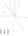
In accordance with embodiments of the present disclosure, to assist a user in achieving a desired movement of the movable object 10 during flight, particularly where the user's perspective is offset from the perspective of the movable object, the controller 22 may be configured to convert the user input from the user's perspective to the perspective of the movable object 10. For example, referring to FIG. 9B, the signal 80 from the terminal 32 (e.g., the signal used to move or rotate the movable object 10 along or about the yaw axis) is assumed to come out of the user's perspective, i.e., along the Z ' axis in the user's coordinate system. Controller 22 converts signal 80 to the perspective of movable object 10 and generates three components 80-X, 80-Y, and 80-Z along the X-axis, axis Y, and Z-axis, respectively, of the local coordinate system. These three components may then be used to command or cause corresponding movement along the X, Y, and Z axes.
By assuming that the user input on terminal 32 is from the user perspective and translating the user input to the perspective of movable object 10, controller 22 and system according to embodiments of the present disclosure allow the user to ignore any offset between the two perspectives and simply indicate the desired movement of movable object 10 from his/her own perspective. For example, if the user wishes to move movable object 10 up and forward (i.e., fly far upward) from his/her perspective, the user may simply tilt the pitch lever on terminal 32. Conventionally, this user input on the terminal 32 would be received by the movable object 10 as a command for movement in the pitch direction of the perspective of the movable object 10. When the movement may actually encompass movement in some or all of the yaw, roll, and pitch directions along the perspective of the movable object 10, through the translation of the controller 22, the movable object 10 will instead move up and forward from the perspective of the user as if the movable object 10 had now presented the perspective of the user.
The controller 22 may perform the conversion between the two views by a matrix transformation, which is implemented by: for example, a matrix representation of the user input is constructed (i.e., in terms of the user coordinate system); the matrix is transformed into a matrix representation of the command input by the user (i.e., in terms of a local coordinate system) based on the offset between the user's perspective and the perspective of the movable object 10.
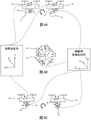
The difference or offset between the user perspective and the perspective of the movable object may be determined in a variety of ways. In one example, as shown in fig. 10, controller 22 may be configured to determine a direction of at least one axis of the user coordinate system and a direction of at least one axis of the local coordinate system based on one or more inputs indicating a direction of each respective axis relative to a reference direction. For example, the controller 22 may be configured to receive a first orientation signal indicative of a direction of a first axis of a local coordinate system of the movable object. The controller 22 may receive a first orientation signal from a first orientation indicator (e.g., a compass, a pointing device, or an inertial measurement unit).
As shown in fig. 10, first orientation indicator 60 may be located on movable object 10 or within movable object 10 and in communication with controller 22. The orientation indicator 60 may be configured to generate a signal indicative of a reference direction (e.g., a compass heading, or other reference direction) and transmit the reference direction to the controller 22. The controller 22 may be configured to determine that the reference direction is the direction of the first axis of the local coordinate system and store the direction in memory for further processing.
The controller 22 may also be configured to receive a second orientation signal indicative of a direction of a first axis of the user coordinate system. The controller 22 may receive a second orientation signal from a second orientation indicator (e.g., a compass, a pointing device, or an inertial measurement unit). As also shown in fig. 10, the second orientation indicator 62 may be located at any location where a user may be positioned or control the movement of the movable object. For example, the second orientation indicator 62 may be located on the terminal 32 or within the terminal 32 and in electronic communication with the controller 22 (e.g., via the communication system 20). The second orientation indicator 62 may be configured to generate a signal indicative of a second reference direction (e.g., a compass heading, or other reference direction) and transmit the second reference direction to the controller 22. The controller 22 may be configured to determine that the reference direction is the direction of the first axis of the user coordinate system and store the direction in memory for further processing.
The controller 22 may be configured to perform a mathematical comparison of the first reference heading indicated by the first orientation indicator 60 and the second reference heading indicated by the second orientation indicator 62 to determine an offset between the local coordinate system of the movable object 10 and the user coordinate system. In this manner, the controller is able to determine an orientation (e.g., angular) offset between a command generated at the user's perspective (i.e., relative to the user's coordinate system) and the final movement of the movable object 10 at the user's perspective based on the command. This offset can then be applied to the command generated at the user's perspective using the perspective transformation to obtain a corresponding command at the perspective of the movable object 10.
Similar mechanisms may be included in movable object 10 and terminal 32 to identify two other axes of the respective coordinate systems and allow controller 22 to determine the difference or offset for each corresponding pair of axes.
Once the three-dimensional offset is determined, controller 22 may generate a transformation matrix to represent such offset, as follows:

the controller 22 will then transform the user input r on the terminal 32, which is then transformed by matrix transformation to produce a signal s of the perspective of the movable object 10:
S=T·r [2]
where r and T are both three-dimensional signals.
The above-described conversion or transformation may take into account the nature of the signal or user-entered command on the terminal 32, i.e. whether the user wishes the movable object 10 to perform a translational or rotational movement.
FIG. 11 illustrates another exemplary embodiment for determining an offset between the perspective of movable object 10 and the perspective of a user. In the example shown in fig. 11, controller 22 may be configured to determine an offset between the perspective of movable object 10 and the perspective of the user based on input from positioning system 64. Controller 22 may be in communication with positioning system 64 (e.g., via communication system 20) and configured to track the position of movable object 10 and the position of a reference point (e.g., terminal 32) relative to a user perspective of a reference coordinate system. That is, the reference point of the user perspective and the movable object 10 may each include a positioning device 66, the positioning device 66 configured to receive and/or generate positioning signals usable by the positioning system 64 to determine the position and/or movement of the movable object 10 and the reference point of the user perspective (e.g., the terminal 32).
Another exemplary method of determining the orientation of at least one axis of the local coordinate system and the user coordinate system of the movable object 10 and determining the offset between the two coordinate systems comprises: the two coordinate systems are initially aligned and their subsequent movement in a single coordinate system is tracked. For example, at the start of a flight maneuver, the user may align his or her perspective with the known direction of at least one axis of the local coordinate system of the movable object 10. For example, before the flight begins, the user may stand in front of, behind, or near the movable object 10, facing himself in the direction of the known axis of the movable object. The user may then provide an input (e.g., button 42) indicating an alignment calibration or simply begin operating the movable object 10. At this point, the controller 22 may begin tracking the movement of the movable object in each direction of the local coordinate system during flight based on the orientation indicators (e.g., inertial measurement units). Using the signals from the orientation indicators, the controller is able to determine the angular displacement of at least one axis of the local coordinate system relative to an initial position at the start of the flight. The difference may indicate a current direction of at least one axis of the local coordinate system. In this way, the controller may be configured to: assuming that the user coordinate system is always aligned with the initial direction at the start of the flight or at calibration, it is determined that the difference between the initial direction and the current direction is the offset between the local coordinate system and the user coordinate system.
Additionally or alternatively, embodiments of the present disclosure may provide for user input that is not necessarily relative to a multi-axis user coordinate system, but rather provide for natural commands, such as commands for turning the movable object 10 to the left or to the right from the user perspective, regardless of the heading of the movable object 10. Controller 22 may be configured to translate such user commands into signals of the perspective of movable object 10 (e.g., the local coordinate system of movable object 10) to effect a change in flight behavior corresponding to the user's requirements. For example, a user input that expects a higher altitude may be translated into a pitch command for the head of movable object 10 to be pointed upward. Typically, the user input will be converted to some combination of linear and/or rotational movement (e.g., pitch, yaw, speed change, etc., as in the case of target tracking).
Target tracking is useful in many situations, such as surveillance and movie or video filming, where a camera carried on the movable object 10 is always filming a moving target and the movable object 10 must be able to follow the target and sometimes move around the target to give the camera a different perspective. Especially in professional film shooting and video production, object tracking offers the following advantages: the user may only need to consider controlling the flight of the movable object 10, while the movable object 10 automatically follows the target and ensures that the target remains in the line of sight of the shot, resulting in more precise flight control, resulting in higher quality imaging results (e.g., photographs and videos).
For example, referring to fig. 12, during target tracking, a user may position movable object 10 to obtain a desired target perception, and then use flight tracking to maintain that perception. To position the movable object 10 to obtain a desired perception, the user may initially control the movable object 10 to fly to a desired position relative to the target and then command the movable object 10 to begin tracking the target. The movable object 10 will then automatically adjust its flight parameters to maintain the target in view. Flight parameters for achieving and maintaining target tracking may include relative position (e.g., linear, angular, etc.), velocity (e.g., linear, angular, etc.), and acceleration parameters (e.g., linear, angular, etc.) of the movable object with respect to the target. In some embodiments, the desired flight parameters may be user specified. For example, controller 22 may be configured to receive one or more input signals from a user via terminal 32 that may indicate the relative height and distance movable object 10 is held relative to a target during flight tracking. In other embodiments, as described above, the user may simply position the movable object so as to give the movable object 10 a desired perception of the target and provide input indicating a desire to track the target in accordance with that perception.
Inputs received by controller 22 from a user relating to target tracking may be received from the perspective of the user and then may be converted to the perspective of movable object 10 in accordance with the exemplary processes discussed above for generating control signals that cause movable object 10 to track a target from a desired location and with desired movement characteristics (e.g., velocity, acceleration, etc.) desired by the user. While the movable object 10 is tracking a target, the user may wish to change one or more tracking parameters (such as the relative distance, velocity or acceleration between the movable object 10 and the target) and generate a command via the terminal 32 to cause such a change from the user's perspective. Such a command may correspond to a user-desired change in perspective of movable object 10 or cargo 14 (e.g., carrier 16, sensing device 19, etc.). The controller 22 may be configured to: a command from the user's perspective is received indicating a desired change to the perspective of movable object 10 or pickup 14, and the command is translated to the perspective of movable object 10 to generate a control signal that causes movable object 10 to track the target from the user's desired perspective in accordance with the exemplary process described above.
In some embodiments, the controller 22 may be configured to receive an input signal from an input device (e.g., button 42 of the terminal 32) as an indication to begin tracking with the current perception of the movable device. In other embodiments, controller 22 may automatically initiate target tracking based on other factors, such as power-on, elapsed time of operation, an indication of the presence of a trackable target, or any other suitable input.
During target tracking, the controller 22 may be configured to make the necessary adjustments to flight parameters (e.g., roll, pitch, yaw, throttle, etc.) in order to track the target, i.e., maintain the perception of the target by the movable object. Perception of the target may refer to characterizing the target by one or more perception parameters corresponding to one or more determinable relative parameters between the movable object and the target. The determinable relative parameters may include, for example, relative position and rotation parameters between the movable object 10 and a reference point or reference object (e.g., a target, the earth's surface, or another object). The relative position parameters and rotation parameters may include a relative distance (e.g., linear distance, radial distance, angular distance, vertical distance, horizontal distance, etc.) between the movable object 10 and the target and a relative velocity (e.g., linear velocity, axial velocity, radial velocity, tangential velocity, angular velocity, etc.) between the movable object 10 and the target.
The perceptual parameters used to characterize perception may vary depending on the method used to perceive the target. For example, as shown in fig. 13, controller 22 may be configured to receive signals indicative of the perception parameters from positioning system 64. The controller 22 may be configured to: signals indicative of the position of the target and the movable object 10 are constantly received from the positioning system. The controller 22 may be configured to: the perceived position of the movable object 10 is continuously compared to the perceived position of the target to continuously determine, for example, the relative distance between the movable object 10 and the target, the relative velocity between the movable objects, and/or other relative parameters.
In other embodiments, a computer vision system may be used to determine perception parameters for characterizing the perception of a target. For example, as shown in FIG. 14A, the movable object may include an imaging device 68 supported by the carrier 16. The imaging device 68 may be configured to generate optical data of the target to identify and track the target. For example, the imaging device 18 may be an optical device (e.g., a camera or a video camera). The imaging device 68 may be configured to generate imaging data indicative of one or more characteristics of the target, such as the height or width of the target. The controller 22 may include or be in communication with an image analyzer 70, the image analyzer 70 being configured to analyze iterations of the imaging data to identify features of the target that may be used to determine relative parameters between the movable object 10 and the target. For example, the image analyzer 70 may be configured to establish a bounding box 72 around the target and monitor how aspects of the bounding box 72 change. For example, as shown in FIG. 14A, in a first imaging iteration, the bounding box 72 may begin near the center of the image window 74. In a second imaging iteration, as shown in FIG. 14B, the image analyzer 70 may determine the position of the bounding box 72 in the image window 74 along the horizontalIs directionally moved by an amount Δ PxAnd is moved by an amount deltap in the vertical directiony. Based on this information, the image analyzer 70 may be configured to determine in which direction the horizontal distance between the movable object 10 and the target has changed. Further, the image analyzer 70 may be configured to observe changes in the height H and width W of the bounding box 72 to determine whether the relative height between the movable object 10 and the target changes.
As shown in fig. 15A, the image analyzer 70 may be configured to detect changes in the width W and height H of the bounding box 72, and determine changes in the relative distance between the movable object 10 and the target. For example, as shown in FIG. 15B, the size of the bounding box 72 may increase in width W and height H as the movable object 10 approaches the target the image analyzer 70 may also be configured to determine a rate of change of a feature of the bounding box 72 to determine a relative velocity between the movable object 10 and the target.
Fig. 15A and 15B illustrate exemplary perception of a target from the perspective of the movable object 10. That is, bounding box 72 at a particular location within image window 74 and having a particular size (e.g., width W and height H) may indicate the current perception of the target from the perspective of movable object 10. The current perspective of the target may also include the relative linear, radial, tangential, and angular velocities of the movable object relative to the target as determined by changes in the bounding box parameters with respect to time. When the perception of the target does not change from the perspective of the movable object 10, the image analyzer 70 may be configured to determine that all relative parameters between the movable object 10 and the target are constant, and thus that the movable object 10 is currently tracking the target with desired tracking parameters.
To maintain a current perception of the target from the perspective of the movable object 10, the controller 22 may be configured to automatically generate one or more control signals for adjusting flight parameters (e.g., roll, pitch, yaw, throttle, etc.) when a change in perception is detected. In one example, the controller 22 may be configured to generate and directly apply control signals to achieve desired flight parameters. In this example, controller 22 may simply generate a command that will cause movable object 10 to conveniently achieve the desired viewing angle. This method may be referred to as a "violence" method. In this case, the user input indicating a longer tracking distance between the movable object 10 and the target may be converted, for example, into a flight control signal that is used to fly the movable object off the target for a period of time and then revert to its previous flight mode once the desired distance is achieved.
In another example, as shown in fig. 16, the controller 22 may be configured to: feedback control of flight parameters is used to maintain the current perception of the target from the perspective of the movable object 10 while providing smoother movement and continuous tracking during flight parameter adjustment. For example, image analyzer 70 may receive imaging data from imaging device 68 and determine a current relative distance D between movable object 10 and the target1. The controller 22 may determine the current relative distance D1At an initial relative distance D0(which may be the desired relative distance or the relative distance from the previous iteration). The feedback controller 76 may be configured to determine an initial relative distance D0And the current relative distance D1Whether there is a difference between them. When the two are the same, the movable object 10 follows at the correct distance and no change in flight parameters is required. When there is a difference, the feedback controller 76 may be configured to determine the control velocity V of the movable object 10 in the direction of the relative distanceCySo as to adjust the current relative distance to match the initial relative distance.
The feedback controller 76 may be configured to perform feedback control using any suitable feedback process. For example, the feedback controller may be configured to perform proportional control (P), integral control (I), derivative control (D), proportional-integral control (PI), or proportional-integral-derivative control (PID). The feedback controller 76 may also or alternatively be configured to apply one or more mathematical filters to perform or enhance the feedback control process. It should be understood that other or additional feedback control and filtering processes may be used.
The actuation system 78 may be configured to generate motion control signals for one or more actuators to achieve a control velocity determined by the feedback controller 76. The control signals generated by the actuation system 78 may control flight parameters (e.g., pitch) in order to move the movable object closer to or further away from the target to achieve the initial relative distance. This process may be repeated a number of times until the initial or desired distance is reached.
Please note that, except for the relative distance D0The process shown in fig. 16 and described above may be performed for other tracking control parameters (e.g., relative altitude, relative radial distance, relative axial distance, relative angular displacement, relative linear velocity, relative radial velocity, relative tangential velocity, relative vertical velocity, etc.), among others. Whenever a difference in one of the tracking control parameters (between the initial value and the current value or between the desired value and the current value) is detected, the feedback process shown in FIG. 16 determines the appropriate flight parameters of the movable object 10 (e.g., the translational velocity in the correct direction and/or the rotational velocity about the correct axis) to reduce the difference between the initial and current parameters and provides a corresponding motion control signal to the movable object 10 to effect any necessary adjustment to the flight parameters. For example, roll, pitch, yaw, and throttle may be adjusted to achieve a determined control velocity along (i.e., translationally) or about (i.e., rotationally) any axis of movement of the movable object 10.
During photo or video capture, the user may change the positional relationship with the moveable object 10 and the camera or other imaging equipment carried thereon, and may also change the positional relationship with the target, due to the user's desire to change the viewing angle of capture or due to movement of the target and the moveable object 10. Thus, the user may wish to have a controlled transition from the first perception to the subsequent perception, and once the movable object reaches the subsequent perception, the controlled maintenance of the subsequent perception continues to produce high quality imaging results.
As one example, the user may wish to change perception by gradually approaching the perception of the target (i.e., shortening the distance between the movable object 10 and the target). To this end, the user may simply actuate an input device (e.g., the first input wrench 38 or of the terminal 32)A second input wrench 40) to generate a command signal. Controller 22 may receive this user input and respond by adjusting one or more flight parameters corresponding to the user input to achieve the desired change in distance. However, the feedback control process shown in FIG. 16 is designed to maintain the initial or desired distance D0(or, a desired perception of a target in the field of view of the movable object 10). Any attempt to adjust the distance by simply changing the flying speed of the movable object 10 will be counteracted by the action of the feedback control process.
According to an embodiment of the present disclosure, the controller 22 may be configured to: determining subsequent or future perception of the target from the perspective of the movable object 10 based on a user command to change a tracking parameter (e.g., following distance) to adjust an initial or desired tracking distance D0To allow the feedback control process to control the movable object 10 in cooperation with the user. For example, as shown in fig. 17, the controller 22 may be configured to perform a feedback control method similar to the method described above in connection with fig. 16 to determine a subsequent or future perception of the target from the perspective of the movable object 10 using the initial position estimator 80. The initial position estimator 80 may be configured to receive data from the image analyzer 70 and input from a user to determine what the future perception of the target from the perspective of the movable object 10 will be based on this information. In the example shown in FIG. 17, this process results in a modified initial or desired distance D0Thereafter, the feedback control process will attempt to maintain this modified distance D between the movable object 10 and the target0。
Referring to fig. 18 and 19, the user input may be a signal generated by an input device, such as the first input wrench 38 or the second input wrench 40 of the terminal 32. The generated signal may be related to changes in target perception, such as changes in the size (e.g., width W and height H) of the bounding box 72 and the resulting corresponding changes in flight parameters (e.g., roll, pitch, yaw, throttle, etc.). In this manner, the initial position estimator 80 (fig. 17) may be configured to determine a subsequent perception of the target that corresponds to a subsequent or desired difference in one or more relative parameters (e.g., relative linear distance, relative angular displacement, relative altitude, relative linear velocity, relative angular velocity, relative radial velocity, relative vertical velocity, etc.) between the movable object and the target.
Referring to fig. 17, subsequent relative parameters determined by the initial position estimator 80 may then be compared to corresponding current relative parameters (e.g., based on the current perception of the target), and the difference may be used for feedback control. In this way, a difference between the current perception and the subsequent perception may result in a difference between the subsequent relative parameter and the current relative parameter, and such a difference in relative parameter may be used to generate a control speed V for moving the movable object 10CyTo hold the object (i.e., bounding box 72) in the image window 74 (refer to fig. 18 and 19) of the image analyzer 70.
In some embodiments, the determined control speed VCyMay be fed back to the initial position estimator 80, and during subsequent iterations of the feedback control process, the initial position estimator 80 may be configured to re-determine subsequent perceptions of the target based on the control velocity to more accurately determine the subsequent perceptions of the target. For example, the feedback controller 76 may determine a control speed for allowing a relative parameter between the movable object 10 and the target to be changed based on the user's input command while preventing the user's input command from moving a bounding box (refer to fig. 18 and 19) in the image window to prevent the tracking process from stopping. Thus, the determined control velocity may be a more realistic velocity at which the movable object 10 will respond to the user input. Thus, a more accurate estimation of the subsequent perception of the target may account for the fact that: the subsequent perception is not actually different from the current perception, since only the user input (and not the control speed) determines the response of the movable object.
In some cases, the accuracy of the perception and perception estimates may also be improved by converting the perception information received by the perception device (e.g., imaging device 68) from the perspective of the sensing device to the perspective of movable object 10. For example, during certain maneuvers (e.g., tracking the target while circling around the target, following an arcuate path, or while performing a slightly abrupt maneuver (e.g., high speed turns, sharp turns, small radius turns, etc.)), the ability to quickly adjust the load 14 (i.e., the imaging device 68) to track the carrier 16 of the target may lead to such situations: the perception of the target from the perspective of the imaging device is slightly different from the perception of the target from the perspective of the movable object 10. In this case, the subsequent perception determined by initial position estimator 80 may be slightly inaccurate, which may result in feedback controller 76 determining that the control speed of movable object 10 is controlled during target tracking to be slightly inaccurate. To account for any offset in the viewing angle between the imaging device 68 or carrier 16 and the movable object 10, the controller may be configured to: the perception information as seen from the perspective of the imaging device 68 or the carrier 16 is received and transformed from the perspective of the imaging device 68 or the carrier 16 to the perspective of the moving object 10. In this manner, subsequent views and commands for controlling flight parameters may more accurately reflect the true view of movable object 10. To perform the perspective transformation, the controller of the movable object 10 may be configured to: constructing a matrix representation of the sensory input from a coordinate system associated with the imaging device 68 or the carrier 16; and transforms the matrix into a matrix representation of the sensory input according to the local coordinate system of the movable object based on the offset between the angle of view of the imaging device 68 or carrier and the angle of view of the movable object 10. The techniques for determining the viewing angle offset as described above may be used.
Sometimes, the movable object 10 is moved around a target (e.g., circular movement) to provide a different perspective to the camera. Fig. 20 shows such a case: the movable object 10 follows a circle of radius r with a radial velocity component VRADV component of tangential velocityTANAnd angular velocity ω to move around the target. The radius r may be maintained or adjusted using the tracking control process described above in connection with fig. 16 and 17. The user may wish to move the movable object 10 faster or slower in order to cause the effect of the imaging result to change. The centrifugal force associated with the circular movement pulling the movable object 10 radially outward may be passed throughThe inward flight of the moving object 10 (e.g., via pitch control) is counteracted. However, the amount of pitch or tilt of the movable object 10 typically has physical limitations due to limitations in the amount by which the carrier or pan/tilt head 16 can tilt. If the tangential velocity VTANExceeds a threshold value VTmaxThe pitch of the movable object 10 will not be able to counteract the centrifugal forces that may eventually cause the movable object 10 to leave the circular orbit, resulting in lost target tracking.
In order to prevent the user from exceeding the maximum allowable tangential velocity VTmaxThe controller of the movable object 10 may be configured to: a maximum allowable tangential velocity for maintaining target tracking is determined and the user's ability to increase the tangential velocity of the movable object 10 as the movable object 10 tracks the target along the circular pattern is limited. For example, the controller 22 may be configured to first determine the radius r of rotation of the movable object 10 about the target. A method for determining a radius r may comprise: the arc length L of the stroke is divided by the angular displacement theta along the arc length, i.e., the arc length L of the stroke may be determined in a number of ways. For example,
 controller 22 may be configured to integrate the tangential velocity of movable object 10 with respect to time to calculate arc length L. And as described above, the tangential velocity of movable object 10 may be determined by analyzing image data collected by imaging device 68 (e.g., a perceived change in the size, shape, and position of a target from the perspective of imaging device 68). In other embodiments, data from a sensing device, such as a GPS system or an Inertial Measurement Unit (IMU), may be collected and analyzed to determine the arc length L traveled by movable object 10 over a period of time. The angular displacement θ of the movable object 10 over the arc length L may be determined as described above by analyzing image data collected by the imaging device 68, such as a perceived change in the size, shape, and position of the target from the perspective of the imaging device 68 (i.e., the optical sensing device), or from image data collected from an infrared imaging device, an ultraviolet imaging device, an x-ray device, an ultrasonic imaging device, a radar device, or the like.
Another method for determining the radius r may be to measure the tangential velocity VTANDivided by the angular velocity ω of the movable object 10, i.e. As described above, the tangential and angular velocities of the
 movable object 10 may be determined by comparing multiple perceptions of the target as seen from the perspective of the movable object with multiple perceptions generated using data collected by the imaging device 68 or other devices (e.g., infrared imaging device, ultraviolet imaging device, X-ray device, ultrasonic imaging device, radar device, etc.). The changes in the size, shape, and position of the target (i.e., bounding box 72) determined during the comparison may correspond to a value of tangential velocity and a value of angular velocity that may be used to determine a radius of rotation of movable object 10.
Another method of determining the radius r is described with reference to fig. 21. As shown in fig. 21, the movable object 10 with the carrier 16 may carry an imaging device (e.g., a camera 82). The camera 82 may capture an image of a target having image coordinates 86 on an image plane 84. Bounding box 72 may also be generated using techniques similar to those described above to analyze geometry and provide continuous and stable results.
As shown in fig. 21, an image of an object may be represented based on an aperture imaging model that assumes that rays from an object point in three-dimensional space may be projected on an image plane to form an image point. The optical axis 88 may pass through the mirror center 90 and the image center. The distance between the mirror center and the image center may be equal to or substantially similar to focal length 92. For illustrative purposes only, the image plane 84 may be moved to a mirror position on the optical axis 88 between the mirror center 90 and the target.
According to various embodiments of the invention, the system may perform initialization steps including estimating a target distance and a target height. Here, the system may determine the relative distance 94 projected onto the ground between the mirror center 90 and the target based on the geometric relationship. The system may then determine a target height.
During the initialization phase (i.e., when t is 0), the system may assume that: the height of the movable object 10 (i.e., camera 82) is measured from the same bottom surface (or horizontal line) as the target is located. Without limitation, when the bottom surface is not a horizontal line, the system may measure the target distance and the target height using an effective height considering a height difference instead of the height of the movable object 10 actually measured.
In the example shown in FIG. 21, in world coordinates, the target may have a top target point (x)t,yt,zt) And a bottom target point (x)b,yb,zb) The two object points are projected on the image plane 84 as top image points (u) in the object image 96t,vt) And bottom image point (u)b,vb). The top line passes through the mirror center 90, the top image point and the top target point and may have an inclination angle 98 with respect to the axis Z of the world coordinates. Furthermore, the base line passes through the mirror center 90, the base image point and the base target point and may have an inclination angle 100 with respect to the axis Z.
Thus, the target top and bottom direction vectors And
And can be expressed as follows.


Where K denotes an inherent matrix of the camera and R denotes a camera rotation.
The system may then estimate the target distance based on the measured or effective camera height 102 and the position of the bounding box 104 in the image coordinates 86. E.g. distance106 may be calculated as d-hc/zb*PbAnd target height 108 may be calculated as ho=hc+ztd/PtWherein P isbIs that Projected length on the ground, and PtIs that
 The projected length on the ground, both defined below.


After the initialization step, the system can estimate the distance to the target 106 even when the target altitude changes (e.g., when the target is off the ground) and when the altitude of the movable object 10 (e.g., UAV) is unknown. This is advantageous because during tracking, objects may climb or descend, and the height of the UAV may be unreliable when it flies through grass or climbs (e.g., 5 meters above the ground).
As shown in FIG. 21, after initialization, the relative distance projected on the ground 106 between the target 10 and the movable object 10 may be calculated as hcWhere dh represents the estimated height of the target in units of distance from the camera, which can be calculated using the following formula.

Thus, the method may be efficient when initialized and may have very few limitations, as the system may estimate the distance to the object 106 based on the height of the target after initialization.
After the radius r of rotation has been determined, the maximum tangential velocity VTmaxCan be controlled by the maximum centripetal acceleration Is determined. The maximum centripetal acceleration of the
 movable object 10 can be determined inherently by its structural design, since, regardless of other flight parameters, the movable object 10 can always reach a certain maximum inclination angle at which it can no longer maintain flight and will stop. In other words, since the movable object 10 is tilted to increase its centripetal acceleration, the maximum acceleration will be reached when the movable object 10 reaches a tilt angle at which it can no longer maintain controlled flight. The maximum angle may be determined empirically or may be provided by the manufacturer of the movable object 10. Thus, let us assume that a is knownmaxCan determine the maximum tangential velocity VTmax。
As the moveable object 10 makes a turn around the target, the controller of the moveable object 10 may be configured to receive a user input (e.g., via one or more input wrenches 38, 40 of the terminal 32) indicating a selection of a desired tangential velocity between the maximum desired tangential velocity and the minimum desired tangential velocity. The controller of the movable object 10 may be configured to receive user input via one or more of a wrench, lever, button, dial, knob, touch screen, or electronic device. In some embodiments, an electronic device may include: a memory and at least one processor configured to execute a program to provide an "app" or one or more graphical user interfaces to receive input from a user for selecting a desired tangential velocity.
As used herein, the term "between" used with reference to a range of values may include the endpoints. That is, the user may provide input indicating a roll setting that may, for example, increase or decrease the tangential velocity of the movable object while circling around the target. When the user moves the input device to adjust the scroll setting up to the maximum displacement, a signal for the maximum scroll setting may be generated. However, applying maximum roll to the movable object may cause it to stop during flight, so the controller 22 may be configured to limit user input and only allow roll-over-position to ensure that the movable object always remains below the maximum tangential velocity determined for the current radius of rotation. That is, the controller of the movable object 10 may set the maximum desired tangential velocity that may be selected to be no greater than a limit value of the maximum allowable tangential velocity of the movable object 10. In this way, the user is prevented from applying too much roll to stop the movable object 10. In some embodiments, the maximum desired tangential velocity that may be selected may be further limited, for example, to a value below the maximum tangential velocity or a percentage of the maximum tangential velocity (e.g., 95%, 90%, 85%, etc.). In this way, the movable object may be made less likely to reach a maximum roll value and suddenly fail to maintain controlled flight.
In some cases, such as when the movable apparatus is wrapping around and tracking a target, the user may wish to increase the radius of rotation r of the movable object or gradually wrap away from the target and terminate the tracking operation, as shown in FIG. 22. To allow the user to perform such manipulations, the user controls of the movable object 10 may be configured to: the maximum desired tangential velocity that can be selected is set to a limit value that is higher than the maximum allowable tangential velocity of the movable object. For example, the maximum desired tangential velocity that can be selected can be set to a value or percentage that will allow the user to gradually increase the radius of rotation of the movable object 10 by increasing the tangential velocity and overcoming the centripetal force acting on the movable object 10. In this way, the controller may be configured to allow the movable object 10 to track the target with a larger radius of rotation or to gradually circle away from the target, and terminate the tracking operation.
It will be apparent to those skilled in the art that various modifications and variations can be made to the disclosed methods and systems. Other embodiments will be apparent to those skilled in the art from consideration of the specification and practice of the disclosed method and system. It is intended that the specification and examples be considered as exemplary only, with a true scope being indicated by the following claims and their equivalents.
Claims (64)
1. A method of controlling a movable object having a first perspective, comprising:
receiving an input signal emanating from a second perspective;
converting the input signal from the second perspective to the first perspective; and
moving the movable object based on the converted signal;
wherein the first perspective corresponds to a first coordinate system with respect to the movable object and the second perspective corresponds to a second coordinate system,
the method further comprises the following steps:
determining a direction of at least a first axis of the first coordinate system;
determining a direction of at least a first axis of the second coordinate system; and
aligning a direction of a first axis of the first coordinate system with a direction of a first axis of the second coordinate system and tracking subsequent movements of the first coordinate system and the second coordinate system.
2. The method of claim 1, further comprising: determining a difference between the first view and the second view.
3. The method of claim 1, wherein the input signal is indicative of a desired movement of the movable object from the second perspective.
4. The method of claim 1, wherein converting the input signal from the second perspective to the first perspective comprises: transforming the desired movement of the movable object as seen from the second perspective into a corresponding movement of the movable object as seen from the first perspective.
5. The method of claim 1, further comprising: determining a difference between the first coordinate system and the second coordinate system.
6. The method of claim 5, wherein the input signal is indicative of a desired movement of the movable object in the second coordinate system.
7. The method of claim 1, further comprising:
receiving a first signal indicative of a direction of a first axis of the first coordinate system; and
determining a direction of a first axis of the first coordinate system based on the first signal.
8. The method of claim 7, wherein the first signal is indicative of at least one of a compass reading, a positioning system signal, or an inertial measurement signal.
9. The method of claim 1, further comprising:
receiving a second signal indicative of a direction of a first axis of the second coordinate system; and
determining a direction of a first axis of the second coordinate system based on the second signal.
10. The method of claim 9, wherein the second signal is indicative of at least one of a compass reading, a positioning system signal, or an inertial measurement signal.
11. The method of claim 10, wherein the second signal is received from an input device configured to generate the input signal.
12. The method of claim 11, further comprising:
tracking the input signal over a period of time to produce a tracking input; and
determining a current direction of the first coordinate system based on the tracking input.
13. The method of claim 1, wherein the difference between the direction of the first axis of the first coordinate system and the direction of the first axis of the second coordinate system is an angular difference.
14. The method of claim 1, wherein:
the input signal is indicative of a command for adjusting perception of a target; and is
The method also includes determining a subsequent perception of the target based on the user input.
15. The method of claim 14, further comprising: generating one or more control signals for moving the movable object based on subsequent perception of the target.
16. The method of claim 14, wherein subsequent perception of the target is determined while tracking the target.
17. The method of claim 16, further comprising:
re-determining subsequent perception of the target using a feedback process; and
generating one or more control signals for moving the movable object based on the re-determined subsequent perception of the target.
18. A system for controlling a movable object having a first perspective, the system comprising:
a controller having one or more processors and configured to:
receiving an input signal emanating from a second perspective;
converting the input signal from the second perspective to the first perspective; and
moving the movable object based on the converted signal;
wherein the first perspective corresponds to a first coordinate system with respect to the movable object and the second perspective corresponds to a second coordinate system,
the controller is configured to:
determining a direction of at least a first axis of the first coordinate system;
determining a direction of at least a first axis of the second coordinate system; and
aligning a direction of a first axis of the first coordinate system with a direction of a first axis of the second coordinate system and tracking subsequent movements of the first coordinate system and the second coordinate system.
19. The system of claim 18, wherein the controller is configured to determine a difference between the first perspective and the second perspective.
20. The system of claim 18, wherein the input signal is indicative of a desired movement of the movable object from the second perspective.
21. The system of claim 18, wherein the controller is configured to: converting the input signal from the second perspective to the first perspective by transforming a desired movement of the movable object from the second perspective to a corresponding movement of the movable object from the first perspective.
22. The system of claim 18, wherein the controller is configured to: determining a difference between the first coordinate system and the second coordinate system.
23. The system of claim 22, wherein the input signal is indicative of a desired movement of the movable object in the second coordinate system.
24. The system of claim 18, wherein the controller is configured to:
receiving a first signal indicative of a direction of a first axis of the first coordinate system; and
determining a direction of a first axis of the first coordinate system based on the first signal.
25. The system of claim 24, wherein the first signal is indicative of at least one of a compass reading, a positioning system signal, or an inertial measurement signal.
26. The system of claim 18, wherein the controller is configured to:
receiving a second signal indicative of a direction of a first axis of the second coordinate system; and
determining a direction of a first axis of the second coordinate system based on the second signal.
27. The system of claim 26, wherein the second signal is indicative of at least one of a compass reading, a positioning system signal, or an inertial measurement signal.
28. The system of claim 27, wherein the second signal is received from an input device configured to generate the input signal.
29. The system of claim 28, wherein the controller is configured to:
tracking the input signal over a period of time to produce a tracking input; and
determining a current direction of the first coordinate system based on the tracking input.
30. The system of claim 18, wherein the difference between the direction of the first axis of the first coordinate system and the direction of the first axis of the second coordinate system is an angular difference.
31. The system of claim 18, wherein
The input signal is indicative of a command for adjusting perception of a target; and
the controller is configured to determine a subsequent perception of the target based on the user input.
32. The system of claim 31, wherein the controller is configured to: generating one or more control signals for moving the movable object based on the subsequent perception of the target.
33. The system of claim 31, wherein the controller is configured to determine a subsequent perception of the target while tracking the target.
34. The system of claim 33, wherein the controller is configured to:
re-determining subsequent perception of the target using a feedback process; and
generating one or more control signals for moving the movable object based on the re-determined subsequent perception of the target.
35. An Unmanned Aerial Vehicle (UAV) system having a first perspective, comprising:
one or more propulsion devices; and
a controller in communication with the one or more propulsion devices and configured to control the UAV to track a target object, the controller comprising one or more processors configured to:
receiving an input signal emanating from a second perspective;
converting the input signal from the second perspective to the first perspective; and
generating one or more signals to control the one or more propulsion devices and move the UAV based on the converted signals;
wherein the first perspective corresponds to a first coordinate system with respect to the movable object and the second perspective corresponds to a second coordinate system,
the processor is configured to:
determining a direction of at least a first axis of the first coordinate system;
determining a direction of at least a first axis of the second coordinate system; and
aligning a direction of a first axis of the first coordinate system with a direction of a first axis of the second coordinate system and tracking subsequent movements of the first coordinate system and the second coordinate system.
36. A non-transitory computer-readable medium storing instructions that, when executed, cause a computer to perform a method of controlling a movable object having a first perspective, the method comprising:
receiving an input signal emanating from a second perspective;
converting the input signal from the second perspective to the first perspective; and
moving the movable object based on the converted signal;
wherein the first perspective corresponds to a first coordinate system with respect to the movable object and the second perspective corresponds to a second coordinate system,
the method further comprises the following steps:
determining a direction of at least a first axis of the first coordinate system;
determining a direction of at least a first axis of the second coordinate system; and
aligning a direction of a first axis of the first coordinate system with a direction of a first axis of the second coordinate system and tracking subsequent movements of the first coordinate system and the second coordinate system.
37. A method for controlling a movable object having a first coordinate system, comprising:
determining a difference between the first and second coordinate systems;
receiving user input indicative of a desired movement of the movable object in the second coordinate system; and
generating a control signal in the first coordinate system based on the user input and a difference between the first coordinate system and the second coordinate system, wherein the control signal is configured to: causing the movable object to move in the first coordinate system corresponding to a desired movement in the second coordinate system;
wherein the method further comprises aligning an initial direction of the first coordinate system with an initial direction of the second coordinate system and tracking subsequent movements of the first and second coordinate systems.
38. The method of claim 37, further comprising:
receiving a first signal indicative of a direction of at least a first axis of the first coordinate system; and
determining a direction of the first coordinate system based on a direction of a first axis of the first coordinate system.
39. The method of claim 38, wherein the first signal is indicative of at least one of a compass reading, a positioning system signal, or an inertial measurement signal.
40. The method of claim 38, further comprising: determining a direction of a second axis of the first coordinate system based on the direction of the first axis of the first coordinate system.
41. The method of claim 38, wherein the user input indicates a desired movement of the movable object along one or more of a first axis and a second axis of the first coordinate system and a rotation about a third axis.
42. The method of claim 38, further comprising:
receiving a second signal indicative of a direction of at least a first axis of the second coordinate system; and
setting a direction of the second coordinate system equal to a direction of a first axis of the second coordinate system.
43. The method of claim 42, wherein the second signal is indicative of at least one of a compass reading, a positioning system signal, or an inertial measurement signal.
44. The method of claim 42, further comprising: determining a direction of a second axis of the first coordinate system based on the direction of the first axis of the first coordinate system.
45. The method of claim 40, wherein the user input indicates a desired movement of the movable object along one or more of a first axis and a second axis of the second coordinate system and a rotation about a third axis.
46. The method of claim 37, wherein the second coordinate system is associated with a control device configured to receive the user input.
47. The method of claim 37, wherein the second coordinate system is associated with a positioning system.
48. The method of claim 47, further comprising determining a direction of a first axis of the first coordinate system based on information received from the positioning system, the direction of the first axis of the first coordinate system indicating the direction of the movable object.
49. The method of claim 37, further comprising:
tracking user input over a period of time to produce tracked user input; and
determining a current direction of the first coordinate system based on the tracked user input.
50. A system for controlling a movable object having a first coordinate system, comprising:
a controller having one or more processors and configured to:
determining an offset between the first coordinate system and a second coordinate system;
receiving user input indicative of a desired movement of the movable object in the second coordinate system; and
generating a control signal in the first coordinate system based on the user input and a difference between the first coordinate system and the second coordinate system, wherein the control signal is configured to: causing the movable object to move in the first coordinate system corresponding to a desired movement in the second coordinate system;
wherein the controller is configured to: aligning an initial direction of the first coordinate system with an initial direction of the second coordinate system and tracking subsequent movements of the first and second coordinate systems.
51. The system of claim 50, wherein the controller is configured to:
receiving a first signal indicative of a direction of at least a first axis of the first coordinate system; and
determining a direction of the first coordinate system based on a direction of a first axis of the first coordinate system.
52. The system of claim 51, wherein the first signal is indicative of at least one of a compass reading, a positioning system signal, or an inertial measurement signal.
53. The system of claim 51, wherein the controller is configured to: determining a direction of a second axis of the first coordinate system based on the direction of the first axis of the first coordinate system.
54. The system of claim 51, wherein the user input indicates a desired movement of the movable object along one or more of a first axis and a second axis of the first coordinate system and a rotation about a third axis.
55. The system of claim 51, wherein the controller is configured to:
receiving a second signal indicative of a direction of at least a first axis of the second coordinate system; and
setting a direction of the second coordinate system equal to a direction of a first axis of the second coordinate system.
56. The system of claim 55, wherein the second signal is indicative of at least one of a compass reading, a positioning system signal, or an inertial measurement signal.
57. The system of claim 55, wherein the controller is configured to: determining a direction of a second axis of the first coordinate system based on the direction of the first axis of the first coordinate system.
58. The system of claim 53, wherein the user input indicates a desired movement of the movable object along one or more of a first axis and a second axis of the second coordinate system and a rotation about a third axis.
59. The system of claim 50, wherein the second coordinate system is associated with a control device configured to receive the user input.
60. The system of claim 50, wherein the second coordinate system is associated with a positioning system.
61. The system of claim 60, further the controller configured to determine a direction of a first axis of the first coordinate system based on information received from the positioning system, the direction of the first axis of the first coordinate system indicating the direction of the movable object.
62. The system of claim 50, wherein the controller is configured to:
tracking user input over a period of time to produce tracked user input; and
determining a current direction of the first coordinate system based on the tracked user input.
63. An Unmanned Aerial Vehicle (UAV) system having a first perspective, comprising:
one or more propulsion devices; and
a controller in communication with the one or more propulsion devices and configured to control the UAV to track a target object, the controller comprising one or more processors configured to:
determining an offset between the first coordinate system and the second coordinate system;
receiving user input indicative of a desired movement of the movable object in the second coordinate system; and
generating a control signal in the first coordinate system based on the user input and a difference between the first coordinate system and the second coordinate system, wherein the control signal is configured to: controlling the one or more propelling devices and causing the movable object to make a movement in the first coordinate system corresponding to a desired movement in the second coordinate system;
wherein the processor is configured to: aligning an initial direction of the first coordinate system with an initial direction of the second coordinate system and tracking subsequent movements of the first and second coordinate systems.
64. A non-transitory computer-readable medium storing instructions that, when executed, cause a computer to perform a method for controlling a movable object having a first coordinate system, the method comprising:
determining an offset between the first coordinate system and a second coordinate system;
receiving user input indicative of a desired movement of the movable object in the second coordinate system; and
generating a control signal in the first coordinate system based on the user input and a difference between the first coordinate system and the second coordinate system, wherein the control signal is configured to: causing the movable object to move in the first coordinate system corresponding to a desired movement in the second coordinate system;
wherein the method further comprises aligning an initial direction of the first coordinate system with an initial direction of the second coordinate system and tracking subsequent movements of the first and second coordinate systems.
Priority Applications (1)
| Application Number | Priority Date | Filing Date | Title |
|---|---|---|---|
| CN202210690884.2A CN114935937A (en) | 2016-02-29 | 2016-02-29 | Method and system for controlling a movable object |
Applications Claiming Priority (1)
| Application Number | Priority Date | Filing Date | Title |
|---|---|---|---|
| PCT/CN2016/074824 WO2017147749A1 (en) | 2016-02-29 | 2016-02-29 | Methods and systems for movement control of flying devices |
Related Child Applications (1)
| Application Number | Title | Priority Date | Filing Date |
|---|---|---|---|
| CN202210690884.2A Division CN114935937A (en) | 2016-02-29 | 2016-02-29 | Method and system for controlling a movable object |
Publications (2)
| Publication Number | Publication Date |
|---|---|
| CN108780316A CN108780316A (en) | 2018-11-09 |
| CN108780316B true CN108780316B (en) | 2022-07-08 |
Family
ID=59742409
Family Applications (2)
| Application Number | Title | Priority Date | Filing Date |
|---|---|---|---|
| CN201680082603.8A Expired - Fee Related CN108780316B (en) | 2016-02-29 | 2016-02-29 | Method and system for movement control of a flying device |
| CN202210690884.2A Pending CN114935937A (en) | 2016-02-29 | 2016-02-29 | Method and system for controlling a movable object |
Family Applications After (1)
| Application Number | Title | Priority Date | Filing Date |
|---|---|---|---|
| CN202210690884.2A Pending CN114935937A (en) | 2016-02-29 | 2016-02-29 | Method and system for controlling a movable object |
Country Status (7)
| Country | Link |
|---|---|
| US (2) | US10946980B2 (en) |
| EP (2) | EP3936961A1 (en) |
| JP (1) | JP6933656B2 (en) |
| CN (2) | CN108780316B (en) |
| DK (1) | DK3398019T3 (en) |
| ES (1) | ES2902469T3 (en) |
| WO (1) | WO2017147749A1 (en) |
Families Citing this family (18)
| Publication number | Priority date | Publication date | Assignee | Title |
|---|---|---|---|---|
| CN105974940B (en) * | 2016-04-29 | 2019-03-19 | 优利科技有限公司 | Method for tracking target suitable for aircraft |
| US9663227B1 (en) * | 2015-12-22 | 2017-05-30 | Gopro, Inc. | Systems and methods for controlling an unmanned aerial vehicle |
| CN106454069B (en) * | 2016-08-31 | 2019-11-08 | 歌尔股份有限公司 | A kind of method, apparatus and wearable device of the shooting of control unmanned plane |
| US10788428B2 (en) * | 2017-09-25 | 2020-09-29 | The Boeing Company | Positioning system for aerial non-destructive inspection |
| JP6560479B1 (en) * | 2018-01-10 | 2019-08-14 | 楽天株式会社 | Unmanned aircraft control system, unmanned aircraft control method, and program |
| CN108596116B (en) * | 2018-04-27 | 2021-11-05 | 深圳市商汤科技有限公司 | Distance measuring method, intelligent control method and device, electronic equipment and storage medium |
| CN113677412B (en) * | 2019-04-08 | 2023-10-10 | 索尼集团公司 | Information processing device, information processing method, and program |
| US20220291679A1 (en) * | 2019-09-11 | 2022-09-15 | Sony Group Corporation | Information processing device, information processing method, information processing program, and control device |
| CN112788227B (en) * | 2019-11-07 | 2022-06-14 | 富泰华工业(深圳)有限公司 | Target tracking shooting method, target tracking shooting device, computer device and storage medium |
| CN114126964A (en) * | 2020-03-31 | 2022-03-01 | 深圳市大疆创新科技有限公司 | Control method and device for movable platform, movable platform and storage medium |
| WO2021199286A1 (en) * | 2020-03-31 | 2021-10-07 | 日本電気株式会社 | Object tracking device, object tracking method, and recording medium |
| JP2021193538A (en) * | 2020-06-09 | 2021-12-23 | ソニーグループ株式会社 | Information processing device, mobile device, information processing system and method, and program |
| JP2022077386A (en) * | 2020-11-11 | 2022-05-23 | ソニーグループ株式会社 | Information processing method, information processing unit and information processing system |
| KR102538666B1 (en) * | 2020-12-04 | 2023-06-01 | 주식회사 팀그릿 | Remote control method for radio control toy and apparatus therefor |
| CN114902151A (en) * | 2020-12-30 | 2022-08-12 | 深圳市大疆创新科技有限公司 | Unmanned aerial vehicle control method and device, unmanned aerial vehicle, terminal, system and storage medium |
| CN113311861B (en) * | 2021-05-14 | 2023-06-16 | 国家电投集团青海光伏产业创新中心有限公司 | Automatic detection method and system for hidden crack characteristics of photovoltaic module |
| CN114674405B (en) * | 2022-03-21 | 2024-03-01 | 广州极飞科技股份有限公司 | Gravity measurement method, gravity measurement device, computer equipment and computer readable storage medium |
| CN114842056A (en) * | 2022-04-19 | 2022-08-02 | 深圳鳍源科技有限公司 | Multi-machine-position first machine visual angle following method, system, device and equipment |
Citations (2)
| Publication number | Priority date | Publication date | Assignee | Title |
|---|---|---|---|---|
| CN103285599A (en) * | 2012-01-04 | 2013-09-11 | 鹦鹉股份有限公司 | Method for intuitive piloting of drone by means of remote control |
| WO2016015251A1 (en) * | 2014-07-30 | 2016-02-04 | SZ DJI Technology Co., Ltd. | Systems and methods for target tracking |
Family Cites Families (18)
| Publication number | Priority date | Publication date | Assignee | Title |
|---|---|---|---|---|
| US8965578B2 (en) * | 2006-07-05 | 2015-02-24 | Battelle Energy Alliance, Llc | Real time explosive hazard information sensing, processing, and communication for autonomous operation |
| US20100250022A1 (en) * | 2006-12-29 | 2010-09-30 | Air Recon, Inc. | Useful unmanned aerial vehicle |
| US8200375B2 (en) * | 2008-02-12 | 2012-06-12 | Stuckman Katherine C | Radio controlled aircraft, remote controller and methods for use therewith |
| US8751063B2 (en) * | 2011-01-05 | 2014-06-10 | Orbotix, Inc. | Orienting a user interface of a controller for operating a self-propelled device |
| FR2972364B1 (en) * | 2011-03-08 | 2014-06-06 | Parrot | METHOD FOR CONTROLLING FOLLOWING A CURVED TURNING OF A MULTI - ROTOR ROTOR SAILING DRONE. |
| EP2511781A1 (en) * | 2011-04-14 | 2012-10-17 | Hexagon Technology Center GmbH | Method and system for controlling an unmanned aircraft |
| JP5854348B2 (en) * | 2011-08-02 | 2016-02-09 | 株式会社マイスタジオ | Remote control method and remote control system |
| KR101978740B1 (en) * | 2012-02-15 | 2019-05-15 | 삼성전자주식회사 | Tele-operation system and control method thereof |
| US20140008496A1 (en) * | 2012-07-05 | 2014-01-09 | Zhou Ye | Using handheld device to control flying object |
| WO2014182730A1 (en) * | 2013-05-06 | 2014-11-13 | Orbotix, Inc. | Multi-purposed self-propelled device |
| CN103345259B (en) * | 2013-07-01 | 2015-09-30 | 哈尔滨工程大学 | Dynamically positioning boats and ships realize the geometric coordinate conversion Guidance control method of position rotating |
| CN106103280B (en) * | 2014-02-28 | 2018-03-30 | 庞巴迪公司 | For controlling the method, system and executable program product of passenger services |
| US9457901B2 (en) * | 2014-04-22 | 2016-10-04 | Fatdoor, Inc. | Quadcopter with a printable payload extension system and method |
| US9817396B1 (en) * | 2014-06-09 | 2017-11-14 | X Development Llc | Supervisory control of an unmanned aerial vehicle |
| CN104898699B (en) * | 2015-05-28 | 2020-03-17 | 小米科技有限责任公司 | Flight control method and device and electronic equipment |
| CN104906805B (en) * | 2015-06-03 | 2017-05-17 | 南京邮电大学 | Safe remote model aerocraft control method and safe remote model aerocraft control system based on active attitude detection |
| US10086309B2 (en) * | 2015-11-25 | 2018-10-02 | Casio Computer Co., Ltd. | Flight device, flight method thrown by user and storage medium |
| US20170269594A1 (en) * | 2016-03-16 | 2017-09-21 | Bryan Sydnor | Controlling an Unmanned Aerial System |
-
2016
- 2016-02-29 EP EP21194307.1A patent/EP3936961A1/en not_active Withdrawn
- 2016-02-29 JP JP2018545148A patent/JP6933656B2/en active Active
- 2016-02-29 WO PCT/CN2016/074824 patent/WO2017147749A1/en unknown
- 2016-02-29 CN CN201680082603.8A patent/CN108780316B/en not_active Expired - Fee Related
- 2016-02-29 DK DK16891942.1T patent/DK3398019T3/en active
- 2016-02-29 EP EP16891942.1A patent/EP3398019B1/en active Active
- 2016-02-29 CN CN202210690884.2A patent/CN114935937A/en active Pending
- 2016-02-29 ES ES16891942T patent/ES2902469T3/en active Active
-
2018
- 2018-08-28 US US16/115,149 patent/US10946980B2/en active Active
-
2021
- 2021-03-01 US US17/189,237 patent/US11572196B2/en active Active
Patent Citations (2)
| Publication number | Priority date | Publication date | Assignee | Title |
|---|---|---|---|---|
| CN103285599A (en) * | 2012-01-04 | 2013-09-11 | 鹦鹉股份有限公司 | Method for intuitive piloting of drone by means of remote control |
| WO2016015251A1 (en) * | 2014-07-30 | 2016-02-04 | SZ DJI Technology Co., Ltd. | Systems and methods for target tracking |
Also Published As
| Publication number | Publication date |
|---|---|
| EP3398019A1 (en) | 2018-11-07 |
| JP2019511044A (en) | 2019-04-18 |
| US20180362185A1 (en) | 2018-12-20 |
| US11572196B2 (en) | 2023-02-07 |
| DK3398019T3 (en) | 2021-12-13 |
| ES2902469T3 (en) | 2022-03-28 |
| US20210276731A1 (en) | 2021-09-09 |
| EP3398019B1 (en) | 2021-10-13 |
| EP3936961A1 (en) | 2022-01-12 |
| JP6933656B2 (en) | 2021-09-08 |
| WO2017147749A1 (en) | 2017-09-08 |
| CN114935937A (en) | 2022-08-23 |
| EP3398019A4 (en) | 2019-04-03 |
| US10946980B2 (en) | 2021-03-16 |
| CN108780316A (en) | 2018-11-09 |
Similar Documents
| Publication | Publication Date | Title |
|---|---|---|
| CN108780316B (en) | Method and system for movement control of a flying device | |
| US10447912B2 (en) | Systems, methods, and devices for setting camera parameters | |
| US10860040B2 (en) | Systems and methods for UAV path planning and control | |
| US11262760B2 (en) | Carrier for unmanned aerial vehicle | |
| EP3317576B1 (en) | Gimbal for image capturing | |
| CN109219785B (en) | Multi-sensor calibration method and system | |
| JP6816156B2 (en) | Systems and methods for adjusting UAV orbits | |
| EP3446190B1 (en) | Systems and methods for coordinating device actions | |
| US11340634B2 (en) | Systems and methods for height control of a movable object | |
| JP6671375B2 (en) | How to fly a drone | |
| US9030149B1 (en) | Systems and methods for payload stabilization | |
| CN103394199A (en) | Method for controlling rotary-wing drone to operate photography by on-board camera with minimisation of interfering movements | |
| EP2964526A1 (en) | Assisted takeoff | |
| US10983535B2 (en) | System and method for positioning a movable object | |
| WO2022134024A1 (en) | Unmanned aerial vehicle with user-interactive components and a foldable structure | |
| JP2021036452A (en) | System and method for adjusting uav locus |
Legal Events
| Date | Code | Title | Description |
|---|---|---|---|
| PB01 | Publication | ||
| PB01 | Publication | ||
| SE01 | Entry into force of request for substantive examination | ||
| SE01 | Entry into force of request for substantive examination | ||
| GR01 | Patent grant | ||
| GR01 | Patent grant | ||
| CF01 | Termination of patent right due to non-payment of annual fee | ||
| CF01 | Termination of patent right due to non-payment of annual fee |
Granted publication date: 20220708 |