CN108495582B - Instrument for advancing an endoscope through the small intestine - Google Patents
Instrument for advancing an endoscope through the small intestine Download PDFInfo
- Publication number
- CN108495582B CN108495582B CN201680062772.5A CN201680062772A CN108495582B CN 108495582 B CN108495582 B CN 108495582B CN 201680062772 A CN201680062772 A CN 201680062772A CN 108495582 B CN108495582 B CN 108495582B
- Authority
- CN
- China
- Prior art keywords
- vacuum
- grasping mechanism
- vacuum port
- blocking element
- endoscope
- Prior art date
- Legal status (The legal status is an assumption and is not a legal conclusion. Google has not performed a legal analysis and makes no representation as to the accuracy of the status listed.)
- Active
Links
Images


Classifications
-
- A—HUMAN NECESSITIES
- A61—MEDICAL OR VETERINARY SCIENCE; HYGIENE
- A61B—DIAGNOSIS; SURGERY; IDENTIFICATION
- A61B1/00—Instruments for performing medical examinations of the interior of cavities or tubes of the body by visual or photographical inspection, e.g. endoscopes; Illuminating arrangements therefor
- A61B1/00064—Constructional details of the endoscope body
- A61B1/00071—Insertion part of the endoscope body
- A61B1/0008—Insertion part of the endoscope body characterised by distal tip features
- A61B1/00094—Suction openings
-
- A—HUMAN NECESSITIES
- A61—MEDICAL OR VETERINARY SCIENCE; HYGIENE
- A61B—DIAGNOSIS; SURGERY; IDENTIFICATION
- A61B1/00—Instruments for performing medical examinations of the interior of cavities or tubes of the body by visual or photographical inspection, e.g. endoscopes; Illuminating arrangements therefor
- A61B1/00064—Constructional details of the endoscope body
- A61B1/00071—Insertion part of the endoscope body
- A61B1/0008—Insertion part of the endoscope body characterised by distal tip features
- A61B1/00082—Balloons
-
- A—HUMAN NECESSITIES
- A61—MEDICAL OR VETERINARY SCIENCE; HYGIENE
- A61B—DIAGNOSIS; SURGERY; IDENTIFICATION
- A61B1/00—Instruments for performing medical examinations of the interior of cavities or tubes of the body by visual or photographical inspection, e.g. endoscopes; Illuminating arrangements therefor
- A61B1/00131—Accessories for endoscopes
- A61B1/00135—Oversleeves mounted on the endoscope prior to insertion
-
- A—HUMAN NECESSITIES
- A61—MEDICAL OR VETERINARY SCIENCE; HYGIENE
- A61B—DIAGNOSIS; SURGERY; IDENTIFICATION
- A61B1/00—Instruments for performing medical examinations of the interior of cavities or tubes of the body by visual or photographical inspection, e.g. endoscopes; Illuminating arrangements therefor
- A61B1/00142—Instruments for performing medical examinations of the interior of cavities or tubes of the body by visual or photographical inspection, e.g. endoscopes; Illuminating arrangements therefor with means for preventing contamination, e.g. by using a sanitary sheath
-
- A—HUMAN NECESSITIES
- A61—MEDICAL OR VETERINARY SCIENCE; HYGIENE
- A61B—DIAGNOSIS; SURGERY; IDENTIFICATION
- A61B1/00—Instruments for performing medical examinations of the interior of cavities or tubes of the body by visual or photographical inspection, e.g. endoscopes; Illuminating arrangements therefor
- A61B1/00147—Holding or positioning arrangements
- A61B1/00148—Holding or positioning arrangements using anchoring means
-
- A—HUMAN NECESSITIES
- A61—MEDICAL OR VETERINARY SCIENCE; HYGIENE
- A61B—DIAGNOSIS; SURGERY; IDENTIFICATION
- A61B1/00—Instruments for performing medical examinations of the interior of cavities or tubes of the body by visual or photographical inspection, e.g. endoscopes; Illuminating arrangements therefor
- A61B1/00147—Holding or positioning arrangements
- A61B1/00151—Holding or positioning arrangements using everted tubes
-
- A—HUMAN NECESSITIES
- A61—MEDICAL OR VETERINARY SCIENCE; HYGIENE
- A61B—DIAGNOSIS; SURGERY; IDENTIFICATION
- A61B1/00—Instruments for performing medical examinations of the interior of cavities or tubes of the body by visual or photographical inspection, e.g. endoscopes; Illuminating arrangements therefor
- A61B1/00147—Holding or positioning arrangements
- A61B1/00154—Holding or positioning arrangements using guiding arrangements for insertion
-
- A—HUMAN NECESSITIES
- A61—MEDICAL OR VETERINARY SCIENCE; HYGIENE
- A61B—DIAGNOSIS; SURGERY; IDENTIFICATION
- A61B1/00—Instruments for performing medical examinations of the interior of cavities or tubes of the body by visual or photographical inspection, e.g. endoscopes; Illuminating arrangements therefor
- A61B1/12—Instruments for performing medical examinations of the interior of cavities or tubes of the body by visual or photographical inspection, e.g. endoscopes; Illuminating arrangements therefor with cooling or rinsing arrangements
- A61B1/126—Instruments for performing medical examinations of the interior of cavities or tubes of the body by visual or photographical inspection, e.g. endoscopes; Illuminating arrangements therefor with cooling or rinsing arrangements provided with means for cleaning in-use
-
- A—HUMAN NECESSITIES
- A61—MEDICAL OR VETERINARY SCIENCE; HYGIENE
- A61M—DEVICES FOR INTRODUCING MEDIA INTO, OR ONTO, THE BODY; DEVICES FOR TRANSDUCING BODY MEDIA OR FOR TAKING MEDIA FROM THE BODY; DEVICES FOR PRODUCING OR ENDING SLEEP OR STUPOR
- A61M25/00—Catheters; Hollow probes
- A61M25/01—Introducing, guiding, advancing, emplacing or holding catheters
- A61M25/0105—Steering means as part of the catheter or advancing means; Markers for positioning
- A61M25/0113—Mechanical advancing means, e.g. catheter dispensers
Abstract
A device for advancing an instrument through the gastrointestinal tract. In some embodiments, the device comprises a first grasping mechanism and a second grasping mechanism adapted to grasp and release tissue of the gastrointestinal tract, the first grasping mechanism being releasably attachable to an instrument, the second grasping mechanism being attached to an outer member configured to at least partially surround the device, the first grasping mechanism and the second grasping mechanism being axially movable relative to each other along the gastrointestinal tract; and a radially expandable blocking element disposed proximal to the first grasping mechanism and movable with the first grasping mechanism relative to the second grasping mechanism, the blocking element adapted to move intestinal tissue relative to the second grasping mechanism when the blocking element is moved toward the second grasping mechanism. The invention also includes a corresponding method.
Description
Cross Reference to Related Applications
This application claims priority from U.S. provisional application No. 62/213,908 entitled "DEVICE FOR initiating patent THROUGH root THE SMALL INTESTINE" filed on 3.9.2015 and U.S. provisional application No. 62/339,593 entitled "DEVICE FOR initiating patent THROUGH root THE SMALLINTESTINE" filed on 20.5.2016, which are all incorporated herein by reference.
Is added by reference
All publications and patent applications mentioned in this specification are herein incorporated by reference in their entirety to the same extent as if each individual publication or patent application was specifically and individually indicated to be incorporated by reference.
Background
Endoscopic insertion into the small intestine is important, for example, for retrieving foreign bodies, obtaining biopsies, removing small bowel tumors or polyps, diagnosing crohn's disease, performing hemostasis of ulcers, adenomas, arteriovenous malformations, or other gastrointestinal bleeding, marking for small bowel surgery. However, current endoscopic procedures cannot be rapidly and reliably advanced through the small intestine.
One system for propulsion through the small intestine is the FujiFilm Double Balloon ('DB') system, which is used as an accessory for an endoscope. The DB system consists of a first latex balloon attached to the end of a scope (scope) and a second latex balloon attached to an outer sleeve. The small intestine may be moved over the endoscope by sequentially inflating the tip balloon to grasp the inside of the small intestine, advancing the deflated overtube balloon, inflating the overtube balloon once the balloon has been fully advanced, pulling back both the overtube and the scope to pleat the small intestine, deflating the tip balloon, re-advancing the scope tip, and repeating the cycle, allowing the small intestine to be probed with the scope. However, the DB system has many disadvantages, resulting in long operation time, poor clinical effect of the operation, and low professional adoption rate.
Thus, there is an unmet clinical need for an instrument that allows easier and faster navigation over the entire length of the small intestine.
Disclosure of Invention
One aspect of the present invention provides a device for advancing an instrument (e.g., an endoscope) through the gastrointestinal tract, the device comprising a first grasping mechanism and a second grasping mechanism adapted to grasp and release tissue of the gastrointestinal tract, the first grasping mechanism being releasably attachable to the instrument, the second grasping mechanism being attached to an external member configured to at least partially surround the instrument, the first grasping mechanism and the second grasping mechanism being axially movable relative to each other along the gastrointestinal tract; and a radially expandable blocking element disposed adjacent to the first grasping means and movable with the first grasping means relative to the second grasping means, the blocking element being adapted to move tissue of the intestinal tract relative to the second grasping means when the blocking element is moved toward the second grasping means.
In some embodiments, the device further comprises an actuator adapted to actuate the first and second grasping mechanisms to grasp and release tissue. The device may further include a connection mechanism configured to releasably attach the first grasping mechanism to the instrument. The outer element may be an outer sleeve, and the outer sleeve may support an actuator line extending to the first and second grasping mechanisms.
In some embodiments, at least one of the first and second grasping mechanisms includes a vacuum port. In some embodiments, in which the second grasping mechanism includes a vacuum port and the instrument is an endoscope, the apparatus further includes a distal cap adapted to cover a distal end of the endoscope and a seal adapted to seal against an outer surface of the endoscope proximal of the cap to form a vacuum chamber in fluid communication with the working channel and the vacuum port of the endoscope. The cap may also have an opening adapted to align with a working channel of an endoscope and a valve disposed in the opening.
In some embodiments, the blocking element comprises a balloon. The device may also include an outer sleeve attached to the balloon and defining a balloon inflation channel in communication with an interior of the balloon.
In some embodiments, the blocking element comprises a plurality of radially movable elements. In some embodiments, the barrier element has a wiping element. In any of the preceding embodiments, the blocking element is configured to slide over at least a portion of the second grasping mechanism.
Another aspect of the invention provides a method of advancing a device through the gastrointestinal tract, comprising the steps of: inserting an instrument comprising a first vacuum port and a second vacuum port into the gastrointestinal tract; advancing a first vacuum port distally through the gastrointestinal tract; initiating a vacuum through the first vacuum port to draw tissue of the gastrointestinal tract to the first vacuum port; sliding the second vacuum port toward the first vacuum port while vacuum is initiated through the first vacuum port; moving tissue proximally through at least a portion of the second vacuum port using a blocking element located proximal to the first vacuum port; initiating a vacuum through the second vacuum port to draw tissue of the gastrointestinal tract to the second vacuum port; and releasing the vacuum on the first vacuum port to allow the first vacuum port to move further distally through the gastrointestinal tract.
In some embodiments, the moving step includes sliding the blocking element over the second vacuum port before initiating the vacuum through the second vacuum port. In some embodiments, the blocking element comprises a balloon.
Some embodiments of the method include the step of expanding the barrier element. Some such embodiments further comprise the step of maintaining the barrier element inflated during all of the advancing, initiating vacuum through the first vacuum port, sliding, resisting, initiating vacuum through the second vacuum port, and releasing steps.
Some embodiments of the invention repeat the following steps: advancing, activating vacuum through the first vacuum port, sliding, blocking, and activating vacuum through the second port, for example, until the instrument has moved through a desired distance, for example, until the instrument has completely passed through the small intestine of the gastrointestinal tract. Some embodiments of the method include the steps of: a viewer (e.g., an endoscope) is inserted into the instrument and passed through the gastrointestinal tract as the instrument is advanced through the tract.
In a further aspect the present invention provides a device for advancement through the gastrointestinal tract, the device comprising first and second grasping mechanisms adapted to grasp and release tissue of the gastrointestinal tract, the first and second grasping mechanisms being movable relative to each other in an axial direction along the gastrointestinal tract; and a radially expandable blocking element disposed proximal to and movable with the first grasping mechanism, the blocking element adapted to enable movement of tissue of the intestinal tract relative to the second grasping mechanism. In some embodiments, the device further comprises an actuator adapted to actuate the first and second grasping mechanisms to grasp and release tissue.
In some embodiments, the first grasping mechanism may be attached to the inner element and the second grasping mechanism is attached to the outer element configured to at least partially surround the inner element. Some such embodiments further comprise a connection mechanism configured to releasably attach the first grasping mechanism to the inner element. The inner element may be, for example, an endoscope and the outer element may be, for example, an overtube. In embodiments provided with an outer sleeve, the outer sleeve may support actuator lines extending to the first and second grasping mechanisms.
In some embodiments, at least one of the first and second grasping mechanisms includes a vacuum port. In some embodiments, the second grasping mechanism includes a vacuum port and the instrument is an endoscope, wherein the device further includes a distal cap adapted to cover a distal end of the endoscope and a seal adapted to seal against an outer surface of the endoscope proximal of the cap to form a vacuum chamber in fluid communication with the working channel and the vacuum port of the endoscope. In some such embodiments, the device may further include an opening in the cap adapted to align with a working channel of an endoscope and a valve disposed in the opening.
In some embodiments, the blocking element comprises a balloon. Some such embodiments further include an outer sleeve attached to the balloon and defining a balloon inflation channel in communication with an interior of the balloon.
In some embodiments, the blocking element comprises a plurality of radially movable elements. In some embodiments, the blocking mechanism comprises a wiping element. In any of the preceding embodiments, the blocking element may be configured to slide over at least a portion of the second grasping mechanism.
In yet another aspect of the invention, a method of advancing a device through the gastrointestinal tract is provided, the method comprising the steps of: inserting an instrument comprising a first port and a second port into the gastrointestinal tract; advancing the first port distally through the gastrointestinal tract away from the second port; sliding the second port toward the first port; moving tissue proximally through the second port using a blocking element located proximal to the first port; activating a vacuum through the second port to draw tissue of the gastrointestinal tract to the second port; and advancing the first port distally through the gastrointestinal tract while activating the vacuum through the second port.
Some embodiments of the method include the step of sliding the barrier element over the second port prior to initiating the vacuum through the second port. In some embodiments, the blocking element comprises a balloon.
Some embodiments of the method include the step of expanding the barrier element. Some such embodiments further comprise the step of maintaining the barrier element expanded throughout the advancing, sliding, arresting, and actuating steps.
Some embodiments of the method repeat the following steps while initiating vacuum through the second port: sliding, blocking, activating, and distally advancing the first port through the gastrointestinal tract, e.g., until the instrument has moved a desired distance, e.g., completely through the small intestine of the gastrointestinal tract.
Some embodiments of the method include the steps of: the viewer is inserted into the instrument and advanced through the gastrointestinal tract as the instrument is advanced through the gastrointestinal tract.
Another aspect of the invention provides a method of advancing a device through the gastrointestinal tract, the method comprising the steps of: inserting an instrument having a first grasping mechanism and a second grasping mechanism into the gastrointestinal tract; actuating a first grasping mechanism to grasp tissue of the gastrointestinal tract; moving the first and second grasping mechanisms toward each other; using a blocking element to push tissue of the gastrointestinal tract proximal to the second grasping mechanism during the moving step; actuating a second grasping mechanism to grasp tissue of the gastrointestinal tract; deactivating the first grasping mechanism; and advancing the first grasping mechanism distally while the second grasping mechanism is activated. In some embodiments, at least one of the first and second grasping mechanisms is a vacuum port.
Some embodiments of the method include the step of sliding the blocking element over the second grasping mechanism prior to activating the second grasping mechanism. In some such embodiments, sliding the blocking element over the second grasping mechanism pushes the pleated tissue of the gastrointestinal tract proximally over the second grasping mechanism.
In some embodiments, the blocking element comprises a balloon. Some embodiments include the step of expanding the barrier element. In some such embodiments, the blocking element remains inflated during all of the steps of activating the first grasping mechanism, moving, arresting, activating the second grasping mechanism, deactivating and advancing.
Some embodiments of the method include the step of deactivating the second grasping mechanism after advancing the first grasping mechanism distally. Some embodiments of the method repeat the steps of: activating the first grasping mechanism, moving, arresting, activating the second grasping mechanism, deactivating the first grasping mechanism, advancing the first grasping mechanism, and deactivating the second grasping mechanism until the instrument has been advanced a desired distance, e.g., until the instrument has completely passed through the small intestine of the gastrointestinal tract.
Some embodiments of the method include the steps of: the viewer is inserted into the instrument and advanced through the gastrointestinal tract as the instrument is advanced through the gastrointestinal tract.
In yet another aspect, the present invention provides a method of advancing a device through the gastrointestinal tract, the method comprising the steps of: inserting an instrument having a first grasping mechanism and a second grasping mechanism into the gastrointestinal tract; actuating a first grasping mechanism to grasp tissue of the gastrointestinal tract; moving the first and second grasping mechanisms toward each other to form a fold of tissue therebetween; moving a fold of tissue proximal to a portion of the second grasping mechanism; actuating a second grasping mechanism to grasp tissue of the gastrointestinal tract distal to substantially all of the tissue plication; and advancing the first grasping mechanism distally while the second grasping mechanism is activated. In some embodiments, at least one of the grasping mechanisms is a vacuum port.
Some embodiments of the method include the step of moving tissue proximally past the second grasping mechanism using a blocking element located proximal to the first grasping mechanism. Some such methods further comprise the step of sliding the blocking element over the second grasping mechanism prior to activating the second grasping mechanism. Sliding the blocking element over the second grasping mechanism may push proximally pleated tissue of the gastrointestinal tract located over the second grasping mechanism. In some embodiments, the blocking element comprises a balloon. In some embodiments, the method may include the step of expanding the barrier element. The blocking element may remain inflated during all steps of activating the first grasping mechanism, moving the first and second grasping mechanisms, moving the tissue plication, activating the second grasping mechanism, and advancing the first grasping mechanism.
Some embodiments of the method repeat the steps of activating the first grasping mechanism, moving the first and second grasping mechanisms, moving the tissue fold, activating the second grasping mechanism, and advancing the first grasping mechanism, e.g., until the instrument has moved a desired distance, e.g., completely through the small intestine of the gastrointestinal tract.
Some embodiments of the method include the step of inserting a scope into the instrument to advance the scope through the gastrointestinal tract as the instrument is advanced through the gastrointestinal tract. In some embodiments, the step of moving the tissue fold proximal to a portion of the second grasping mechanism includes sliding an element of the instrument over the second grasping mechanism.
Basically, in one embodiment, a method of advancing an instrument through a gastrointestinal tract comprises: (1) inserting an instrument comprising a first vacuum port and a second vacuum port into the gastrointestinal tract; (2) advancing a first vacuum port distally through the gastrointestinal tract; (3) initiating a vacuum through the first vacuum port to draw tissue of the gastrointestinal tract to the first vacuum port; (4) sliding the second vacuum port toward the first vacuum port when the first vacuum port is activated; (5) preventing tissue from moving distally past a blocking element positioned proximal to the first vacuum port; (6) initiating a vacuum through the second vacuum port to draw tissue of the gastrointestinal tract to the second port; (7) releasing the vacuum of the first vacuum port; and (8) advancing the first vacuum port distally through the gastrointestinal tract.
This and other embodiments may include one or more of the following features. The method may further include sliding the barrier element over the second vacuum port prior to initiating vacuum through the second vacuum port. Sliding the blocking element over the second vacuum port may push the pleated tissue of the gastrointestinal tract proximally over the second vacuum port. The blocking element may comprise a balloon. The method may further comprise expanding the barrier element. The method may further comprise maintaining the barrier element inflated throughout the advancing.
Basically, in one embodiment, a method of advancing an instrument through a gastrointestinal tract comprises: (1) inserting an instrument comprising a first port and a second port into the gastrointestinal tract; (2) advancing the first port distally through the gastrointestinal tract away from the second port; (3) sliding the second port toward the first port; (4) preventing tissue from moving distally past a blocking element proximal to the first port; (5) activating a vacuum through the second port to draw tissue of the gastrointestinal tract to the second port; and (6) advancing the first port distally through the gastrointestinal tract.
This and other embodiments may include one or more of the following features. The method may further include sliding the barrier element over the second vacuum port prior to initiating vacuum through the second port. Sliding the blocking element over the second port may push the pleated tissue of the gastrointestinal tract over the second port proximally. The blocking element may comprise a balloon. The method may further comprise expanding the barrier element. The method may further comprise maintaining the barrier element inflated throughout the advancing.
Basically, in one embodiment, an apparatus for advancing a scope through a gastrointestinal tract includes a first vacuum, a second vacuum and a blocking element proximal to a first vacuum port. The first vacuum port is configured to maintain a fixed position relative to the viewer. The second vacuum port is configured to slide relative to the first vacuum port. A blocking element proximal to the first vacuum port includes a radially expandable portion.
This and other embodiments may include one or more of the following features. The first vacuum port or the second vacuum port may further include a plurality of vacuum holes extending therearound. The blocking element may be a balloon. The blocking element may be configured to slide over at least a portion of the second vacuum port.
Basically, in one embodiment, a method of advancing an instrument through a gastrointestinal tract comprises: (1) inserting an instrument having a first grasping mechanism and a second grasping mechanism into the gastrointestinal tract; (2) actuating a first grasping mechanism to grasp tissue of the gastrointestinal tract; (3) moving the first and second grasping mechanisms toward each other; (4) stopping tissue of the gastrointestinal tract from moving distally past the first grasping mechanism with the blocking element; (5) actuating a second grasping mechanism to grasp tissue of the gastrointestinal tract; (6) deactivating the first grasping mechanism; and (7) advancing the first grasping mechanism distally while the second grasping mechanism is activated.
This and other embodiments may include one or more of the following features. At least one of the gripping mechanisms may be a vacuum port. The method may further include sliding the blocking element over the second grasping mechanism prior to activating the second grasping mechanism. Sliding the blocking element over the second vacuum port may push proximally pleated tissue of the gastrointestinal tract over the second grasping mechanism. The blocking element may comprise a balloon. The method may further comprise expanding the barrier element. The method may further comprise maintaining the barrier element inflated throughout the advancing.
Basically, in one embodiment, an apparatus for advancing a viewer through a gastrointestinal tract includes a first tissue grasping mechanism, a second tissue grasping mechanism, and a blocking element proximal to the first tissue grasping mechanism. The first tissue grasping mechanism is configured to maintain a fixed position relative to the viewer. The second tissue grasping mechanism is configured to slide relative to the first tissue grasping mechanism. A blocking element proximal to the first tissue grasping mechanism includes a radially expandable portion.
This and other embodiments may include one or more of the following features. The blocking element may be configured to slide over at least a portion of the second tissue-grasping mechanism. The blocking element may be a balloon. The first or second grasping mechanism may be a vacuum port.
Basically, in one embodiment, a method of advancing an instrument through a gastrointestinal tract comprises: (1) inserting an instrument having a first grasping mechanism and a second grasping mechanism into the gastrointestinal tract; (2) actuating a first grasping mechanism to grasp tissue of the gastrointestinal tract; (3) moving the first and second grasping mechanisms toward each other to form a fold of tissue therebetween; (4) moving a fold of tissue proximal to a portion of the second grasping mechanism; (5) actuating a second grasping mechanism to grasp tissue of the gastrointestinal tract distal to substantially all of the tissue plication; and (6) advancing the first grasping mechanism distally while the second grasping mechanism is activated.
This and other embodiments may include one or more of the following features. At least one of the gripping mechanisms may be a vacuum port. The method may further include preventing tissue of the gastrointestinal tract from moving distally past the first grasping mechanism with the blocking element. The method may further include sliding the blocking element over the second grasping mechanism prior to activating the second grasping mechanism. Sliding the blocking element over the second vacuum port may push proximally pleated tissue of the gastrointestinal tract over the second grasping mechanism. The blocking element may comprise a balloon. The method may further comprise expanding the barrier element. The method may further comprise maintaining the barrier element inflated throughout the advancing. Moving the tissue fold proximal to a portion of the second grasping mechanism may include sliding an element of the instrument over the second grasping mechanism.
Basically, in one embodiment, an apparatus for advancing a viewer through a gastrointestinal tract includes a first vacuum port, a second vacuum port, and a blocking element configured to slide over a portion of the second vacuum port. The first vacuum port is configured to maintain a fixed position relative to the viewer. The second vacuum port is configured to slide relative to the first vacuum port.
This and other embodiments may include one or more of the following features. The first vacuum port or the second vacuum port may further include a plurality of vacuum holes extending therearound. The blocking element may be a balloon. The blocking element may be configured to slide over at least a portion of the second vacuum port.
Basically, in one embodiment, a device for advancing a viewer through a gastrointestinal tract includes a blocking element and a vacuum port. The blocking element is configured to be in a fixed position relative to the viewer. The blocking element includes a radially expandable portion. The vacuum port is configured to slide relative to the first blocking element.
This and other embodiments may include one or more of the following features. The first vacuum port may include a plurality of vacuum holes extending therearound. The blocking element may be a balloon. The blocking element may be configured to slide over at least a portion of the second vacuum port.
Basically, in one embodiment, an instrument for advancing a scope through a gastrointestinal tract includes a blocking element and a grasping mechanism proximal to the blocking element. The blocking element is configured to be in a fixed position relative to the viewer. The blocking element includes a radially expandable portion. A grasping mechanism proximal to the blocking element is configured to slide over at least a portion of the grasping mechanism.
This and other embodiments may include one or more of the following features. The grasping mechanism may be a vacuum port. The blocking element may be a balloon. The blocking element may be configured to slide over at least a portion of the second vacuum port.
Basically, in one embodiment, an instrument for advancing an endoscope through a gastrointestinal tract includes a vacuum port attached to an outer cannula. The outer sleeve is configured to be positioned around the viewer. The outer sleeve is configured to create a reciprocating enclosed volume and vacuum seal between an inner periphery of the outer sleeve and an outer periphery of the endoscope.
Drawings
The novel features of the invention are set forth with particularity in the appended claims. A better understanding of the features and advantages of the present invention will be obtained by reference to the following detailed description that sets forth illustrative embodiments, in which the principles of the invention are utilized, and the accompanying drawings of which:
fig. 1A-1C show various views of an instrument for endoscopic advancement through the small intestine.
Fig. 2A-2B illustrate various views of a distal vacuum port of an instrument for endoscopic advancement through the small intestine.
Fig. 3A-3D illustrate various views of another embodiment of a distal vacuum port.
Fig. 4 illustrates another embodiment of a distal vacuum port.
Fig. 5 illustrates another embodiment of a distal vacuum port.
Fig. 6 illustrates another embodiment of a distal vacuum port.
Fig. 7A-7C illustrate various views of another embodiment of a distal vacuum port.
Figures 8A-8E illustrate various views of a blocking element of an instrument for endoscopic advancement through the small intestine.
Fig. 9A-9C show various views of the legs of the blocking element.
Fig. 10A-10B illustrate various views of a seal of a barrier element.
Fig. 11 shows the strut of the blocking element and the return spring.
Fig. 12A-G illustrate an exemplary method of activating a blocking element.
Figures 13A-13B illustrate various views of another embodiment of a blocking element.
Figures 14A-14B illustrate various views of another embodiment of a blocking element.
Fig. 15 shows a further embodiment of the blocking element.
Figures 16A-16D illustrate various views of another embodiment of a blocking element.
Fig. 17 shows another embodiment of the blocking element.
Figures 18A-18D illustrate various views of another embodiment of a blocking element.
Fig. 19A-19D illustrate various embodiments of an overtube for an instrument for endoscopic advancement through the small intestine.
20A-20B illustrate various views of one mechanism for attaching a telescoping vacuum tube to the outer tube of an instrument for endoscopic advancement through the small intestine.
Figures 21A-21C show various views of another mechanism for attaching a telescoping vacuum tube to the outer tube of an instrument for endoscopic advancement through the small intestine.
FIG. 22 shows an embodiment of a telescoping vacuum tube attached to the outer tube of an instrument for endoscopic advancement through the small intestine.
FIG. 23 shows another embodiment of a telescoping vacuum tube attached to the outer tube of an instrument for endoscopic advancement through the small intestine.
Fig. 24A-24B illustrate different modes of extending the distal vacuum line from the distal vacuum port.
Fig. 25A-C show various views of the handle of the instrument for endoscopic advancement through the small intestine.
Fig. 26A-26C show various views of the handle of the instrument for endoscopic advancement through the small intestine.
27A-27B illustrate a cross section of a spool valve of a handle of an instrument for endoscopic advancement through the small intestine.
Fig. 28 shows another embodiment of a blocking element of an instrument for advancement through the small intestine.
Fig. 29A-E illustrate attachment of an instrument for endoscopic advancement to an endoscope.
Fig. 30A-30H illustrate use of the instrument for endoscopic advancement within the small intestine.
Fig. 31A-F illustrate the use of the instrument for endoscopic advancement in the small intestine.
FIGS. 32A-G illustrate an embodiment of an endoscopic propulsion instrument having an inflatable blocking element.
Fig. 33A-33C illustrate a distal vacuum port that includes axially extending arms for increased flexibility.
Fig. 34A-34C illustrate another embodiment of a distal vacuum port that includes axially extending arms for increased flexibility.
Fig. 35A-C illustrate a distal vacuum port that includes a laser cutting coil for added flexibility.
Fig. 36A-36C illustrate a distal vacuum port that includes an annular connector for added flexibility connected to a wire connector.
Fig. 37A-37C illustrate another embodiment of a distal vacuum port that includes a loop connector for increased flexibility connected to a wire connector.
Fig. 38A-38C illustrate a distal vacuum port that includes a living hinge for increased flexibility.
39A-39D illustrate an instrument for endoscopic advancement in the small intestine with a blocking element axially spaced from the distal vacuum port.
Fig. 40A-40C illustrate a proximal vacuum port comprising a single wall.
Fig. 41 illustrates another embodiment of a proximal vacuum port comprising a single wall.
42A-42B illustrate a proximal vacuum port that includes two aperture arrays.
FIGS. 43A-43B illustrate another embodiment of a proximal vacuum port.
Fig. 44A-44D illustrate a proximal vacuum port formed as an extension of an outer cannula.
Fig. 45 shows a proximal vacuum port with a stiffening coil.
FIG. 46 shows the sealed space between the endoscope and the overtube.
Fig. 47A-I illustrate an instrument having an extendable needle for inflation of a balloon blocking element.
Fig. 48A-D illustrate another embodiment of the instrument with an extendable needle for inflation of the balloon blocking element.
Fig. 49A-B illustrate a distal vacuum port that includes an indicator element for indicating proper docking of the proximal vacuum port within the blocking element.
Figures 50A-F illustrate exemplary wiping elements.
FIGS. 51A-F illustrate another exemplary wiping element.
Fig. 52A-F illustrate an exemplary blocking element.
Fig. 53A-53H illustrate an exemplary handle for controlling inflation of the proximal vacuum port.
Fig. 54A-D illustrate a portion of an exemplary handle for controlling inflation of a proximal vacuum port.
Fig. 55A-C illustrate exemplary valves at the working channel end of the scope.
56A-D illustrate an exemplary proximal vacuum port having a rib extending on an inner circumference and a circular aperture.
57A-D illustrate an exemplary proximal vacuum port having a rib and rectangular aperture extending on an inner circumference.
Fig. 58A-C illustrate another example of a balloon stop element.
FIG. 59 shows another embodiment of an instrument for endoscopic advancement through the small intestine.
FIG. 60 illustrates another embodiment of an instrument for endoscopic advancement through the small intestine.
Figures 61A-61C illustrate various designs of a dual overtube instrument for endoscopic advancement through the small intestine.
62A-B illustrate various views of another embodiment of an instrument for endoscopic advancement through the small intestine.
Fig. 63A-B illustrate various views of another embodiment of an instrument for endoscopic advancement through the small intestine.
FIG. 64 shows another embodiment of an instrument for endoscopic advancement through the small intestine.
Fig. 65 shows an exemplary system configuration.
Fig. 66A-H illustrate another embodiment of an instrument for endoscopic advancement through the small intestine, the instrument including an outer cannula connected to a balloon blocking element for inflating the balloon blocking element.
FIG. 67 shows an instrument for endoscopic advancement through the small intestine having an inflatable element located on the proximal vacuum port.
Fig. 68 shows an instrument for endoscopic advancement through the small intestine with the proximal vacuum port replaced by an inflatable element.
Figures 69A-69C illustrate various radial expansion mechanisms for the blocking element.
Fig. 70A-70B illustrate another embodiment of a proximal vacuum port.
Detailed Description
Basically, the instruments described herein are configured to allow an endoscope or other instrument to be advanced through the small intestine. These instruments include first and second grasping mechanisms, such as vacuum ports, that are slidable relative to each other and that can be sequentially activated to grasp and release tissue of the small intestine. These instruments may also include a blocking element that pushes the grasped tissue proximally, allowing the tissue to fold and ensuring effective movement of the instrument and endoscope through the small intestine.
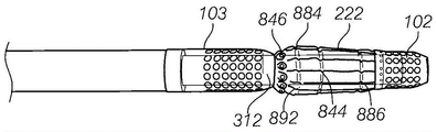
Referring to fig. 1A-1C, an exemplary instrument 100 is configured to straddle an internal element such as an endoscope 101. Other internal components such as sheaths, tools, etc. may be used with the propulsion device of the present invention. Instrument 100 includes a distal vacuum port 102 and a proximal vacuum port 103. The distal vacuum port 102 is configured to attach to the endoscope 101, while the proximal vacuum port 103 attaches to an outer sleeve 104 that extends over the endoscope 101. Further, the vacuum ports 102/103 are configured to be axially slidable relative to each other (see, e.g., the transition from fig. 1A to fig. 1C). A telescoping vacuum line 105 extends from the distal vacuum port 102 and through the outer cannula 104. In addition, another vacuum line 106 extends to the proximal vacuum port 103. Instrument 100 further includes a blocking element 222 axially movable with distal vacuum port 102 and located proximal to distal vacuum port 102, distal vacuum port 102 being configured to expand upon initiation of axial movement by proximal vacuum port 103. Handle 107 controls the relative movement of ports 102, 103, blocking element 222 and the vacuum applied thereto through vacuum lines 105, 106.
Referring to fig. 31A-31F, another exemplary instrument 3100 is configured to straddle an endoscope 3100 to advance a viewer through a lumen 3131, such as the small intestine. The instrument 3100 is similar to the instrument 100 and includes a distal vacuum port 3102 and a proximal vacuum port 3103. However, the distal vacuum port 3102 in this configuration is attached to the endmost end of the endoscope 3101, while the proximal vacuum port 3103 is attached to an outer sleeve 3104 that extends over the endoscope 3101. Vacuum ports 3102/3103 are configured to be axially slidable relative to one another, as described for instrument 100. Instrument 3100 also includes a strut 3110 extending connected to and proximally from the distal vacuum port 3102, and a blocking element 3122 connected to strut 3110 proximal to the distal vacuum port 3102, such that blocking element 3122 and distal vacuum port 3102 move with endoscope 3101. In this embodiment the blocking element 3222 is an inflatable balloon, and the proximal vacuum port 3103 is configured to slide thereunder when the endoscope 3101 is pulled proximally relative to the outer sleeve 3104.
Gripping mechanism/vacuum port
The instruments described herein may include a distal grasping mechanism, such as a distal vacuum port, configured to grasp tissue, and a proximal grasping mechanism, such as a proximal vacuum port, configured to grasp tissue. The proximal and distal grasping mechanisms may be movable relative to each other. Many of the embodiments described herein include a vacuum gripping mechanism. However, for any of these embodiments, the proximal and/or distal vacuum gripping mechanisms may be replaced with an inflatable element such as a balloon. Further, although many of the embodiments described herein include two grasping mechanisms, these instruments may be used with only one grasping mechanism, e.g., only a proximal grasping mechanism.
Distal vacuum port
The distal vacuum port can be configured to connect to a scope and/or remain axially fixed relative to the scope. In some embodiments, as shown in fig. 1A-1C, the distal vacuum port 102 can be configured to attach to the endoscope 101 just proximal of the steerable portion of the scope, e.g., just proximal of a bump formed at the connection between the steerable and flexible portions. In this embodiment, the port 102 leaves the steerable portion substantially uncovered. In other embodiments, referring to fig. 32A-32C, the distal vacuum port 3202 can be configured to be attached to the distal-most tip of the endoscope 3201 (see also instrument 3100 in fig. 31).
Referring to fig. 2A-2B, in some embodiments, a connection mechanism 123, such as a split collet, can allow the distal vacuum port 102 to be clamped around the endoscope. The attachment mechanism 123 can also include mating threads 145, 147 that tighten around the distal vacuum port 102 of the endoscope when the mating threads 145, 147 are rotated relative to each other. Alternative attachment mechanisms include set screws or interference fit components. Referring to fig. 32A-G, in some embodiments, the distal vacuum port 3202 can be attached with a shear clip 3245 (see fig. 32E), which can be placed within a shear clip dropout prevention feature 3246 (see fig. 32D-E). Other attachment mechanisms are possible, such as split clamps or set screws (see fig. 33A-33C) or elastic bands.
In some embodiments, the distal vacuum port may comprise a double wall port, wherein a vacuum is created between the walls. For example, referring to fig. 2A-2B, distal vacuum port 102 includes an inner cylindrical portion 202B and an outer cylindrical portion 202A with a sealed space 220 therebetween. A plurality of holes 230 extend through the outer cylindrical portion 202a into the sealed space 220. Further, a vacuum line 105 extends into the sealed space 220 to provide a vacuum thereto. The holes 230 may be disposed along the outer circumference of the outer cylindrical portion 202 a. The holes 230, which may be circular, may be further arranged in an array around the periphery of the outer cylindrical portion 202 a. In one embodiment, there may be five circumferential rows of holes 230.
In other embodiments, the distal vacuum port may comprise a single wall port, wherein a vacuum is created between the single wall and the viewer. Thus, for example, as shown in fig. 32A-32C, the distal vacuum port 3202 can be sealed to the scope 3201 with an end cap 3296 and an O-ring 3271a or sealing box, thereby providing a sealed vacuum chamber between a single wall of the distal vacuum port 3202 and the scope 3201. A hole 3230 extending through the wall of port 3202 allows tissue to be suctioned thereto.
In some embodiments, the distal vacuum port may include a connector therein to ensure that the distal tip of the endoscope can still flex or move without being obstructed by the distal vacuum port. Thus, the connector can be passed over the steering portion of the endoscope without interfering with its original articulating capabilities, thereby allowing the distal vacuum port to be placed at the end of the scope (as shown in FIGS. 32A-32C). The connector may be useful even if the distal vacuum port is placed at a more proximal location by allowing the scope to flex more easily, for example, when it is bent within a narrow radius inside the patient. The hinge portion may withstand and/or accommodate torsion, tension and compression, and may have low bending forces.
For example, referring to fig. 33A-33C, distal vacuum port 3302 may include axially extending arms 333 having vacuum channels therethrough that may enhance the flexibility of distal tip 3302. Fig. 34A-34C illustrate another distal vacuum port 3402 that includes a long axially extending arm 3434. In contrast to port 3302 of fig. 33A-33C, port 3402 comprises a single wall vacuum design, allowing for sealing around the inflation port of a viewer for inflation of the barrier element, and attachment with a shear clip rather than a set screw. Referring to fig. 35A-35C, as another example, distal vacuum port 3502 includes a laser cutting coil 3535 extending therearound to enhance flexibility. As another example, referring to fig. 36A-36C, the distal tip 3602 can include a loop-shaped plastic connector 3661 coupled with a wire connector 3663. The wire connector 3663 may be a portion of a single wire (or two) that is wrapped and bonded around all of the connectors 3661. Connector 3661 may be made from, for example, a high stiffness plastic such as Acrylonitrile Butadiene Styrene (ABS), polycarbonate, thermoplastic polyurethane, high density polyethylene, PEEK, Ultem, or mineral filled plastic. The wire may be made of, for example, stainless steel or nitinol, and may be a solid wire, a spring wire, or a multi-wire cable. Referring to fig. 37A-C, as another example, similar to the distal tip 3602, the distal tip 3702 can include an annular plastic connector 3771 connected together with a wire connector 3762. However, in this embodiment, the wire connection 3762 is a stub portion (i.e., not part of a continuous wire) present at each junction. Referring to fig. 38A-38C, as another example, the distal tip 3802 includes a living hinge 3881 cut therein to allow bending or flexing. Thus, the tip 3802 may be made, for example, from a laser cut cylindrical material or by depositing a different material with rapid prototyping. In some embodiments, the tip 2802 may be made from injection molded polypropylene or from nitinol.
All of the distal tip embodiments shown in fig. 33A-38C advantageously help increase the flexibility of the distal vacuum port to avoid interfering with the movement of the scope (e.g., for portions that substantially include maneuverability and/or more proximal region bending for the scope). Other mechanisms for increasing the flexibility of the distal vacuum port are also possible. For example, the distal tip may include a coil reinforced elastomer, a braid over an angled spiral cut, a connector made so that they may be angled relative to each other when captured, or steel metal that is cut, bent, and welded with a joint. In one example, the instrument distal vacuum port may include a braided covering with a thin elastomeric or plastic sealing tube. The sealed tube may be coated or plated to provide enhanced features, such as stiffness.
Other embodiments of the distal vacuum port are shown in fig. 3A-6. As shown in fig. 3A-3D and 5-6, the aperture of the distal vacuum port may be circular or non-circular (e.g., square, oval, rectangular, hexagonal, or hexagonal with rounded corners), as shown in fig. 4. Further, as shown in fig. 6, the distal vacuum port may have raised ridges around the edges of the hole to help increase suction. The ridge may be made of a single material or multiple materials and may include a flexible elastomer and/or a highly conformable flange. Further, in some embodiments, the distal vacuum port may be slidable relative to the endoscope rather than being attached to the endoscope. In some embodiments, a strut may connect the inner and outer cylindrical portions of the distal vacuum port to provide structural support therebetween.
The aperture of the proximal and/or distal vacuum ports may be between 0.02 inches and 0.16 inches. The size of the holes may be selected to optimize redundancy, manufacturability, vacuum strength, and resistance to external and internal debris blockage.
The distal vacuum port may include a distal tip. For example, as shown in fig. 2A-2B, the distal vacuum port 102 can include a rounded atraumatic distal end 112.
Proximal vacuum port
The proximal vacuum port may be attached to the outer cannula and may be configured to slide relative to the endoscope.
In some embodiments, the proximal vacuum port may include a double wall and a vacuum chamber therebetween. 7A-7C, proximal vacuum port 103 can include inner and outer cylindrical portions 302b and 302a and a sealed space 320 therebetween. A plurality of apertures 330 extend through the outer cylindrical portion 302a and into the sealed space 320. Further, a vacuum line 106 extends into the sealed space 320 to provide a vacuum thereto. Also, a channel 335 may extend axially therethrough to pass a vacuum line of the distal port.
In other embodiments, the proximal vacuum port can include a single wall, and a vacuum can be created between the wall and the viewer. For example, fig. 40A-40C illustrate a single wall port 4003 configured to form a vacuum chamber with the outer wall of the viewer 4001. Further, the proximal vacuum port 4003 can comprise a seal 4040. As shown in fig. 40A-40C, the seal 4040 may be a conical seal, which may advantageously be tolerant of irregular surfaces. As shown in fig. 40A-40C, in some embodiments, the seal 4040 can have a taper facing in the distal direction. As shown in fig. 41, in some embodiments, the seal 4140 may have a taper facing in the proximal direction. The seal may be made of a material such as silicone or thermoplastic polyurethane, which provides low resistance as the seal moves along the viewer. In some embodiments, the seal may be mounted in a rigid box to maintain dimensional integrity. In addition, the seal may help maintain the vacuum (i.e., avoid vacuum leakage) while allowing the tissue region distal to the seal to be insufflated, as described further below.
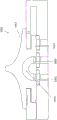
Referring to fig. 46, in some embodiments, the instrument 4600 may include a distal seal 4640 and a proximal seal 4646. The two seals may form a trapping volume between them and between the inner surface of the outer sleeve 4604 and the outer surface of the endoscope 4601. This volume may be filled with water and/or other fluids to provide a lubricious layer between the outer sleeve 6404 and the endoscope 4601. The two seals 4604, 4646 may prevent lubricant from leaking out during operation.
The aperture of the proximal vacuum port may be between 0.02 inches and 0.16 inches. The size of the holes may be selected to optimize redundancy, manufacturability, vacuum strength, and resistance to external and internal debris blockage. The holes may have various shapes, such as circular, square, oval, rectangular, hexagonal, or hexagonal with rounded corners. Further, the apertures of the vacuum ports may be arranged in a variety of different patterns. For example, referring to FIGS. 7A-7C, the apertures 330 may be disposed along the outer periphery of the outer cylindrical portion 302 a. The holes 330, which may be circular, may be further arranged in an array around the periphery of the outer cylindrical portion 302 a. For proximal vacuum port 103, aperture 330 may extend through a longer axial length than distal vacuum port 102. For example, in one embodiment, there may be seven circumferential rows of holes 330 (as opposed to five of the distal vacuum ports 102). The increased length of the area covered by the aperture 330 may advantageously increase the grip of the proximal vacuum port 103. 40A-40C, the apertures 4030 may be part of a single array or, as shown in FIGS. 42A-42B, the apertures 4230 may be arranged in a plurality of different arrays 4224a, 4224B axially separated from one another. In some embodiments, the different arrays 4224a, 4224b may be activated independently of each other. For example, distal-most array 4224b may be released when pushed under the blocking element to prevent it from aspirating portions of the blocking element and/or trapping tissue between the blocking element and the distal portion of port 4203.
The proximal vacuum port may also include a tapered distal end. The tapered distal end of the proximal vacuum port may be longer than the tapered distal end of the distal port. Referring to fig. 7A-7C, in some embodiments, the tapered distal end 312 can include a plurality of flexures 313 therein, the flexures 313 being configured to allow the end 312 to closely ride on the outer diameter of the endoscope (e.g., to prevent tissue from being pinched between the scope and the port 103) while providing a degree of flexure at locations where the outer diameter of the endoscope is increased (e.g., at a ridge between the steerable end and the flexible portion). Alternatively, referring to fig. 43A-43B, the tapered end 4312 may be made of an elastomeric material such that it remains against the viewer, limits grip, goes under the blocking element, does not bend, and has no cracks or lacerations that could trap things.
In some embodiments, referring to fig. 44A-44C, the proximal vacuum port 4403 can be formed as an extension of the outer sleeve itself (i.e., rather than being bonded or otherwise attached thereto). Further, as shown in fig. 45, in embodiments where the proximal vacuum port is formed as an extension of an overtube and/or in embodiments where the proximal vacuum port is a separate piece, a stiffening coil 4554 or spring may be placed around the distal vacuum port 4503 to prevent port 4503 from collapsing under vacuum.
In some embodiments, the proximal vacuum port may include ribs along its inner perimeter to help prevent the port from collapsing under vacuum. For example, fig. 56A-D illustrate a proximal vacuum port 5603 that includes a longitudinal rib 5616 extending therein. The ribs 5616 are rounded so as to allow the proximal vacuum port 5603 to slide freely along the viewer 5601. Fig. 57A-D show a similar proximal vacuum port 5703 with ribs 5716, but the holes 5730 in this embodiment are square instead of circular.
In some embodiments, referring to fig. 70A-70B, the proximal vacuum port 7003 can include a flexible portion 7070 and a rigid portion 7071 along its length. For example, the flexible portions 7070 and the rigid portions 7071 may be in an alternating pattern along the length. Rigid portion 7071 may include vacuum holes 7030 therein. In some embodiments, flexible portion 7071 can comprise a helical material (as shown in fig. 70B). The vacuum port 7003 can be made, for example, by laser cutting a vacuum hole 7030 in the tube and a spiral design. As shown in fig. 70A, the vacuum port 7003 can also include a tapered distal tip 7012. In some embodiments, the distal tip 7012 may comprise a separate piece of material that is attached to the remainder of the port 7003. Additionally, the tip 7012 and/or the entire port 7003 can be wrapped and/or coated with a material, such as urethane and/or a hydrophilic material, to help smooth the tip and prevent trauma. The flexible portion 7070 may advantageously ensure that the proximal vacuum port 7003 flexes with the endoscope during advancement through the small intestine.
Barrier element
The blocking elements described herein may be configured to radially expand (i.e., such that the overall radial dimension of the blocking element increases from the collapsed configuration to the expanded configuration). The increased radial dimension of the blocking element may prevent the pleated tissue from moving distally past the blocking element, thereby ensuring proper transfer of the tissue to the proximal vacuum port. In some embodiments, the proximal vacuum port extends between 0.5 inches and 2 inches, such as about 1 inch, below the blocking element. The blocking element moves with the distal grasping mechanism and in various embodiments is attached to the distal grasping mechanism or to an endoscope (or other instrument) to which the distal grasping mechanism is attached.
Referring to fig. 8A-8E, in one embodiment, blocking element 222 of instrument 100 may include a flexure 842, a return spring 844, and a rolling seal 846. The flexure 842 may be configured to attach to the distal vacuum port 102. Further, as shown in fig. 8A-8E and 9A-9C, the flexure 842 may include a plurality of rigid struts 882, with two hinges 884, 886 in each rigid strut 882. There may be a circumferential array of struts 882, for example 6 to 12 struts, for example 9 struts. The flexures 842 may be configured to bend at the hinges 884, 886 to allow the struts to extend radially outward such that the blocking element 222 may expand to a larger overall diameter. Proximal hinge 884 can be configured to flex inwardly, while distal hinge 886 can be configured to flex outwardly, such that when hinges 884, 886 flex, a proximal wall is formed by proximal end 892 of strut 882. Moreover, as described further below, the flexure 842 may be configured to expand when axially compressed by the proximal vacuum port 103. In some embodiments, the flexures 842 may be injection molded from polypropylene. In some embodiments, the hinges 884, 886 are living hinges.
Referring to fig. 8A and 11, the return spring 844 may be configured to return the flexure to its unexpanded, neutral position. In one embodiment, the spring 844 may be located within a groove 832 (see fig. 8B and 8C) of the flexure 842. The spring 844 may be, for example, an elastic band or ring that surrounds the strut 882. Alternatively, the return spring function may be achieved by fabricating the high stiffness flexure 886.
Referring to fig. 8A-8E, rolling seal 846 may be attached to a proximal end of flexure 842 and may be configured to tightly slide along an outer diameter of proximal vacuum port 103 when moved relative to proximal vacuum port 103. With reference to fig. 8A-8E and 10A-11B, seal 846 may thus include a resilient annular member 863 and a plurality of attachment mechanisms 865 configured to attach to attachment mechanisms 887 on flexure 842. For example, attachment mechanism 887 on flexure 842 may be a radially extending post or pin, while attachment mechanism 865 on rolling seal 846 may be a small annular elastic ring configured to fit over the post or pin to attach seal 846 to flexure 842. The resilient annular member 863 may be configured to stretch radially as it slides along the tapered distal surface 312 of the proximal vacuum port 103. In one embodiment, rolling seal 846 may be cast from urethane. Alternatively, the rolling seal 846 may be attached to the flexure 842 by insert molding the rolling seal 846 and flexure 842 together.
Referring to fig. 12A-12G, the position of the blocking element 222 is fixed relative to the position of the distal vacuum port 102. The blocking element 222 may be activated (i.e., radially expanded) by axial relative movement between the proximal vacuum port 103 and the distal vacuum port 102. In the initial configuration shown in fig. 12A, the proximal vacuum port 103 may be in a retracted position relative to the blocking element 222 and the distal vacuum port 102. Proximal vacuum port 103 and distal vacuum port 102 may then be moved axially toward each other to bring proximal vacuum port 103 into contact with blocking element 222, as shown in fig. 12B. Referring to fig. 12C, when proximal vacuum port 103 is pushed against seal 846, it causes flexure 222 to bend at hinges 884, 886 such that distal portion 892 extends radially outward. As shown in fig. 12D, once the flexure 222 is fully expanded by movement of the hinges 884, 886, the proximal and distal vacuum ports 103, 102 may continue to move axially toward each other, forcing the tapered end 312 to slide under the seal 846. The flexure 222 may thus continue to expand as the seal 846 moves along the taper 312 and over the aperture 330 of the proximal vacuum port 103. Relative axial movement of proximal vacuum port 103 relative to distal vacuum port 102 may continue until proximal vacuum port 103 encounters the proximal end of distal vacuum port 102 and/or until aperture 330 of proximal vacuum port 103 is fully covered by blocking element 222. Referring to fig. 12E, as the vacuum port 103 and blocking element 222 move apart, the diameter of the blocking element 222 will decrease due to the radially inward force provided by the return spring 844. The proximal vacuum port 103 may then be fully retracted, as shown in fig. 12F-12G.
Other embodiments of the blocking element are shown in fig. 13A-18D and 28. In the embodiment of fig. 13A-13B, blocking element 1322 comprises a rigid link 1313 configured to pivot. The O-ring 1314 holds the blocking member 1322 in the constrained configuration. Connector 1313 may be configured to pivot out and increase its diameter when activated by axial movement of the proximal vacuum port. In the embodiment of fig. 14A-B, stop member 1422 may be similar to fig. 1322, but may be fully resilient. The stop member 1422 may flex or stretch. In the embodiment of fig. 15, the blocking element 1522 may include a connection 1513 that may be integrated directly into the distal vacuum port. In the embodiment of fig. 16A-16D, the blocking element 1622 may include both rigid and flex regions. In the embodiment of fig. 17, the blocking element 1722 may comprise an inflatable cuff 1717. In the embodiment of fig. 18, blocking element 1822 may comprise a sheath, such as a braided sheath, configured to be compressed to produce radial expansion when activated by axial movement of the proximal vacuum port. The braids may be configured to move relative to one another and/or may be welded or attached at some or all of the intersections. The blocking element 1822 may advantageously be flexible, smooth, small, and simple. The braid and connector may be formed with a continuous skin so that there are no pinch points. In the embodiment of fig. 28, the blocking element and the distal vacuum port are combined into a single unitary structure. As shown, in such embodiments, the vacuum holes may be positioned along the legs of the barrier element.
Another example blocking element 5222 is shown in fig. 52A-52F. As described with reference to the blocking element 222, the blocking element 5222 is activated by contact with the proximal vacuum port and includes a plurality of connections 5252a-5252e at the proximal end of the tube 5253. The connectors 5252A-5252e can be configured to pivot such that the tips of the connectors 5252A-5252e rotate from a distal position flush with the tube 5253 (fig. 52A-C) to a proximal position extending radially outward from the tube 5253 (fig. 52D-F). In some embodiments, the spring mechanism may be configured to hold the connections 5252a-5252c downward when in the collapsed position.
In some embodiments, the blocking element may be an inflatable element, such as a balloon. For example, fig. 39A-D illustrate a balloon barrier element 3922 (fig. 39C-D illustrate a deflated balloon barrier element 3922, while fig. 39A-B illustrate an inflated balloon barrier element 3922). The balloon 3922 is advantageously flexible and atraumatic to avoid damaging tissue as instruments are passed therethrough. In some embodiments, balloon 3922 may be a compliant balloon. In other embodiments, the balloon may be non-compliant. 39A-39B, the balloon blocking element 3922 may have a larger radius than the scope 3901 after inflation. Further, in some embodiments, the radius of the proximal portion of the balloon may be greater than the radius of the distal portion of the balloon. For example, the balloon may have a conical shape. The balloon may be symmetrical about viewer 3901 to help center the viewer during movement through the lumen.
Further, in some embodiments, the blocking element is separate from (i.e., not integral with) the distal vacuum port. For example, as shown in fig. 39A-39D, the instrument 3900 may include a balloon blocking element 3922 separate from the distal port 3902. Separating blocking element 3922 from distal port 3902 advantageously allows blocking element 3922 to be placed proximal to the steering portion of scope 3901, thereby improving the docking of the proximal port within blocking element 3922. Thus, as shown in fig. 39A, the balloon blocking element 3922 may be configured to be located directly proximal to the bump 3992 on the scope 3901.
Any of the barrier elements described herein may include a wiper element on a proximal end thereof that is configured to facilitate movement of the pleated tissue over the proximal vacuum port while ensuring that no tissue is pinched thereunder during relative movement between the proximal vacuum port and the barrier element. For example, referring to fig. 32G, balloon stop element 3222 is attached over wiper element 3250, wiper element 3250 includes a rigid sleeve 3261 and a plurality of flexures 3293 at its proximal end. As the proximal port moves toward it, the flexure 3293 expands outward, thereby enabling the proximal port to move within the space 3265 to interface within the stop element 3222. The blocking element 3222 may be attached to the viewer by a friction fit.
As yet another example, referring to fig. 58A-C, balloon barrier element 5822 is attached to wiper element 5850 (see fig. 58C) which includes an elastomeric sleeve 5891 reinforced with a coil. The coil reinforcement sleeve 5891 advantageously prevents collapse under vacuum while allowing some flexibility without buckling when bent. The wiper element also includes an outwardly extending flexure 5893, similar to flexure 3293. The bayonet fitting 5882 on the distal end twists into the rest of the unit and compresses the conical piece below it to hold the unit in place proximal to the bump in the viewer.
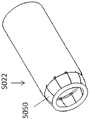
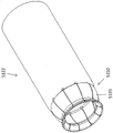
As yet another example, referring to FIGS. 50A-F, the barrier element 5022 (a radially expandable element of the barrier element 5022, such as a balloon, not shown for clarity) includes a wiper element 5050. The wiping element 5050 includes a plurality of flexures 5093 configured to expand (fig. 50D-E) or contract (fig. 50A-C) as the vacuum port extends thereunder which it extends over the vacuum port. An elastomeric O-ring 5095 at the proximal end holds the proximal end of the flexure 5093 together and expands and contracts with the flexure. Fig. 51A-51F illustrate another embodiment of a barrier element 5122 having a wiper element 5150 (again, for clarity, a radially expandable element such as a balloon is not shown). The wiping element 5150 includes a flexure 5193 that is similarly configured to expand and contract. In this embodiment, the flexure 5193 is hinged. FIGS. 51A-51C show an expanded flexure 4193, while FIGS. 51D-F show a contracted flexure.
Other embodiments of the wiping element are also possible. For example, the wiping element may include a teflon segment, a coated O-ring, a hinged segment, a coil spring, or an iris pattern. In some embodiments, the wiping element can also include a low friction coating or be made of an inherently low friction material (e.g., polypropylene, Teflon @, or FEP). The wiping element can be configured to minimize contact with the proximal vacuum port, thereby reducing friction. For example, only the O-ring and/or only the tip of the flexure may contact the proximal vacuum port as it passes from below.
In some embodiments, when the blocking element is a balloon, inflation of the balloon blocking element may occur by inflation through an existing inflation port on the viewer. For example, as shown in fig. 32A, inflation port 3292 from endoscope 3201 may be sealed using O- rings 3271a, 3271b to provide inflation to balloon blocking element 3222. An enlarged view of the inflation port 3292 and surrounding O- rings 3271a, 3271b can be seen in fig. 32F.
In embodiments where the balloon blocking element is moved distally, the line may travel from the inflation port to the blocking element for inflation. For example, fig. 39A-D show an inflation line 3939 extending from the distal end of the inflation port of the viewer back to the balloon blocking element 3922.
In other embodiments, the balloon blocking element may be inflated by an inflation line (e.g., a telescoping inflation line) extending down the working channel of the viewer, or by an inflation line extending through the outer sleeve or along the outer perimeter of the viewer.
Referring to fig. 47A-1, in some embodiments, an extendable tube or needle 4774 (see fig. 47B) may be attached to the proximal port 4703 to assist in inflation of the balloon blocking element 4722. Thus, needle 4774 may be stored within the walls of proximal port 4703 (fig. 47C). When the proximal port 4703 is fully seated within the blocking element 4722, the needle 4774 may extend outward to provide access to the inflation port 4792 (fig. 47D), and fluid may be supplied through the needle 4774 and the port 4792 to inflate the balloon blocking element 4722 (fig. 47E). The needle may then be withdrawn into proximal port 4703 (fig. 47F). Fig. 47H-I illustrate a cross-section of the distal end of proximal port 4703 that may include a plurality of self-sealing apertures 4747 for delivering a plurality of needles therethrough.
A similar embodiment is shown in fig. 48A-D. The distal end of proximal port 4803 can include a solid rubber element instead of an array of holes. Needle 4874 may be used to pierce a rubber element to inflate barrier element 4822.
In other embodiments, the balloon blocking element may be inflated through an annular channel formed between the additional outer sleeve and the viewer. That is, referring to fig. 66A-H, the apparatus 6600 may include a balloon stop element 6622 attached to an additional outer sleeve 6666, the additional outer sleeve 6666 extending through the handle 6607 to the balloon stop element 6622. An annular space or lumen 6667 is formed between the outer sleeve 6666 and the viewer 6601 through which fluid or gas can be supplied to the balloon barrier element 6622 (e.g., through a balloon inflation inlet port 6669). An insufflation supply port 6668 in communication with the annular space or lumen 6667 may be located on the outer sleeve 6666 and/or configured as part of the handle 6607. This embodiment also has a tissue grasping mechanism (distal vacuum port 6602 and proximal vacuum port 6603) as discussed above for other embodiments.
The blocking element herein is described as radially expanded. This radial expansion includes any increase in the overall radius from the collapsed configuration to the expanded configuration, regardless of the process or direction of expansion. Thus, for example, referring to FIG. 69A, the blocking element 6922a may extend only in the radial direction. Further, as shown in fig. 69B, the blocking element 6922B may extend in a tangential direction while still causing overall radial expansion. Similarly, as shown in fig. 69C, the blocking element 6922C may extend in the direction of rotation while causing a general radial expansion.
Outer sleeve design
Referring back to fig. 1A-1C, the outer sleeve 104 can be configured to straddle the endoscope 101 and can be attached to the proximal vacuum port 103. In addition, referring to fig. 19A-19D, the overtube can be designed to include multiple lumens configured to retain the endoscope and vacuum lines 105, 106 therein.
For example, as shown in fig. 19A, the overtube 1904 may be a multi-lumen extrusion having a large central lumen 1921 for the endoscope, a side lumen 1923 for one of the vacuum lines 105, 106, and a separate tube 1925 attached thereto for the other vacuum line 105, 106. The outer sleeve 1904 may advantageously allow for the joining of different structures made of different materials, potentially providing an effective composite structure (e.g., having very high push stiffness but very low bending stiffness).
Referring to fig. 19B, the overtube 2004 may include a single lumen extrusion with an inner lumen 2021 for the endoscope and two separate tubes 2035, 2033 attached for the vacuum lines 105, 106. The two separate tubes 2035, 2033 may be inside the inner chamber 2021 as shown, or may be outside the inner chamber 2021. Further, the shape of the inner cavity 2021 or the outer diameter of the tube 2004 may be modified to include grooves or channels/dimples for the individual tubes 2035, 2033.
Referring to fig. 19C, the outer sleeve 2104 may be a multi-lumen extrusion having a large central lumen 2121 for the endoscope and two lumens 2145, 2145 for the vacuum lines 105, 106.
Referring finally to fig. 19D, the outer cannula 2204 may include a large central lumen 2221 for the endoscope and redundant small lumens 2245a-2245D in the wall for the vacuum lines. The redundant lumens advantageously ensure a working vacuum even if one of the lumens is blocked.
Vacuum connection to distal port
The distal vacuum port may be connected to the vacuum by a vacuum line running down the side of the viewer (e.g., a telescoping line), by a tube extending down the working channel, or by a vacuum applied to the working channel itself.
Referring to fig. 1A and 1C, in some embodiments, the vacuum tube 105 connected to the distal vacuum port may be a telescoping tube that telescopes within the outer sleeve 104 to allow movement and/or vacuum supply of the distal vacuum port 102 and endoscope 101 relative to the handle 107.
Referring to fig. 20A-23, a telescoping vacuum tube 105 may be attached to the endoscope 101 to ensure that the proximal vacuum port can be easily moved thereon. The attachment mechanism may be configured to: (1) holding tube 105 against endoscope 101; (2) freely slide relative to the proximal vacuum structure and the small intestine; (3) preventing lateral movement of the vacuum tube 105; and/or (4) ease of installation. An exemplary method of attachment is shown in fig. 20A-23. Referring to fig. 20A-20B, vacuum tube 105 may be attached to endoscope 101 with an adhesive such as tape (e.g., an adhesive or heat seal). Referring to fig. 21A-21C, tube 105 may be attached to endoscope 101 with coil 2072. The coil 2072 may extend entirely around the endoscope 101 or partially around the endoscope 101. The coil 2072 may be made of, for example, stainless steel (e.g., 007 "), nitinol, or plastic. Referring to fig. 22, a vacuum tube 105 may be retracted onto the endoscope 101, for example activated by heat, chemical or UV light. Finally, referring to fig. 23, the tube 105 may be sealed by a stretchable material 2372 made of, for example, urethane or latex, which is rolled over the endoscope 101 and the tube 105.
Referring to fig. 24A, in some embodiments, a vacuum line 105 may extend from the distal vacuum port 102 to access the working channel of the endoscope 101. In this embodiment, the vacuum line 105 may be coiled around the tip of the endoscope 101 so as not to interfere with tip deflection. In embodiments where the distal vacuum port is mounted on the tip, the vacuum line may enter the working channel directly. In addition, the working channel may be used to provide vacuum to the vacuum line 105. At the outlet there may be a flapper valve that is normally closed to maintain the vacuum path, but the flapper valve may be pushed open by the instrument so that the working channel may still act as the instrument working channel. In other embodiments, referring to fig. 24B, vacuum line 105 may extend proximally from distal vacuum port 102 toward the handle.
Referring to fig. 32A, in some embodiments, working channel 3233 itself can be used to provide vacuum through channel 3297. A valve 3232 (e.g., a duckbill valve) in an opening in the end cap 3296 prevents vacuum from being drawn out of the distal end of the channel 3233, but still allows the working element to pass therethrough. Another embodiment of a distal tip 5502 with a duckbill valve 5532 is shown in figures 55A-55C.
Handle (CN)
The instruments described herein may have a handle, actuator, or controller for actuating the grasping mechanism and/or blocking element.
For example, referring to fig. 25A-25C, handle 107 may include a handle body 2510, handle body 2510 having a distal opening 2505 configured to mount to an outer cannula. Handle 107 may also include a large central lumen 2504 configured to straddle an endoscope and a vacuum attachment 2502. Handle 107 can also include a slide valve assembly 2508, slide valve assembly 2508 configured to control the release of vacuum to the proximal or distal vacuum lines via vacuum lumen connectors 2507a, 2507 b. User-activated buttons 2503a, 2503b may be configured to interface with spool valve assembly 2508 to manually control the release of vacuum. Vents 2509a, 2509b may also be positioned within the system to release vacuum pressure substantially immediately upon release of the vacuum.
As shown in fig. 26A-26C, the handle 107 may be configured to easily fit in a user's hand. In addition, handle 107 may be designed to allow a user to both grasp the handle and actuate buttons 2503a, 2503b with one hand.
In some embodiments, the vacuum input 2502 may be removed to provide flushing. In other embodiments, handle 107 may include a separate flush port with a valve for the vacuum line.
The spool valve assembly 2508 is shown in greater detail in fig. 27A-27B. The spool valve housing 2648 includes annular or curved (toroidal) grooves or rings 2601, 2602, 2603, 2604, 2605. In addition, annular grooves 2610, 2612, 2614 may extend along the spool 2638. Each ring may be connected to a different component of the system. For example, ring 2601 can be connected to a first vent 2509a, ring 2602 can be connected to a vacuum lumen 2507a for a distal vacuum port, ring 2603 can be connected to a vacuum input 2502, ring 2604 can be connected to a vacuum lumen 2507b for a proximal vacuum port, and ring 2605 can be connected to a second vent 2509 b. Thus, referring to fig. 27A, when button 2503a is fully pushed in, a first connection is made between annular ring 2603 (connected to vacuum input 2502) and annular ring 2604 (connected to vacuum lumen 2508b for the proximal vacuum port) through groove 2612, and a second connection is made between annular ring 2601 (connected to first vent 2509a) and annular ring 2602 (connected to vacuum lumen 2507A for the distal vacuum port) through groove 2610. As a result, a vacuum may be applied to the proximal vacuum port and a vent may be applied to the distal vacuum port. Conversely, referring to fig. 27B, when the button 2503B is fully pushed in, a first connection may be made between the ring 2602 (connected to the vacuum lumen 2507a for the distal vacuum port) and the ring 2603 (connected to the vacuum input 2502) by the groove 2612, and a second connection may be made between 2604 (connected to the vacuum lumen 2508B for the proximal vacuum port) and 2605 (connected to the second vent 2509B) by the groove 2614. As a result, a vacuum may be applied to the distal vacuum port while the proximal vacuum port is used for ventilation.
Another exemplary handle 5307 is shown in fig. 53A-53H. The handle 5307 can include a reel mechanism 5359 configured to connect the proximal vacuum port to a vacuum source. Thus, as shown in fig. 53A, the reel mechanism 5359 can include a vacuum input chamber 5331, a proximal vacuum chamber 5332 connected to the second vacuum port, and a third chamber 5333 configured to vent to atmosphere. The spool 5336 can be moved proximally and distally using the button 5353 (via the connector 5354). Thus, fig. 53A shows a spool 5356 configured to connect chambers 5331 and 5332 together, allowing a vacuum to be applied to the proximal vacuum port through line 5355. In contrast, fig. 53B shows chambers 5332 and 5333 connected together, thereby deactivating the proximal vacuum port (and venting to atmosphere).
In this embodiment, vacuum is supplied to the distal port through the working channel of the endoscope. As such, vacuum control through the distal vacuum port may be performed by a button or vacuum activation mechanism on the viewer itself.
Fig. 54A-D illustrate an alternative embodiment of a handle 5407 that can be used to control the vacuum supplied to the proximal vacuum port. In this embodiment, the handle 5407 includes three chambers: 5431 (for vacuum input), 5432 (for proximal vacuum port), and 5433 (for venting to atmosphere). The U-shaped channel 5455 moves back and forth with the button 5453 to connect the chambers as desired. Thus, fig. 54C shows suction disconnected (chamber 5432 for vacuum port connected to chamber 4333 for venting to atmosphere). In contrast, fig. 54D shows suction/vacuum on (chamber 5431 for vacuum input connected to chamber 5432 for proximal vacuum port). In use
The instruments described herein may be used to quickly and efficiently move an endoscope through the small intestine.
For example, referring to fig. 29A-E, instrument 100 may first be coupled to an internal member desired by a user to be advanced through the gastrointestinal tract (or other lumen), such as endoscope 101. First, referring to FIG. 29A, an endoscope 101 may be placed through a handle 107. As shown in fig. 29B, the endoscope 101 may be advanced through the overtube 104 until the endoscope 101 exits the overtube 104 and the handle 107 is proximate to the proximal end of the endoscope 101. As shown in fig. 29C, the telescopic line 105 may then be attached to the endoscope 101 (e.g., to avoid entanglement during use). As shown in fig. 29D, the distal tip 102 may then be attached to the endoscope 101. Finally, as shown in fig. 29E, a vacuum may be attached to vacuum input 2502 on handle 107.
Once established (as shown in FIGS. 29A-29E), endoscope 101 and attached instrument 100 may be inserted into the small intestine, such as the mouth or rectum (as shown in FIGS. 30A-30H). As shown in fig. 30A, the endoscope 101 and instrument 100 can be advanced to the beginning of the small intestine 3001. As shown in fig. 30B, the distal vacuum port 102 of the instrument 100 and the endoscope 101 can then be advanced further into the small intestine 3001, for example, approximately 18 to 24 inches, by pushing the endoscope forward. As shown in fig. 30C, the distal vacuum port 102 can then be activated to draw tissue of the small intestine 3001 therein. As shown in fig. 30D, the space between the distal vacuum port 102 and the proximal vacuum port 103 can be reduced by pulling on the proximal end of the endoscope until the proximal vacuum port hits the blocking element 222. As this relative movement between the vacuum sections 102, 103 occurs, the tissue of the small intestine 3001 is pleated. Referring to fig. 30E, distal vacuum port 102 may continue to be pulled proximally over proximal vacuum port 103, causing blocking element 222 to radially expand. As the blocking element 222 expands, a wall is formed that blocks the tissue plication from moving distally over the distal vacuum port 102. Further, as the distal vacuum port 102 is pulled proximally, the proximal vacuum port 103 moves completely inside the blocking element 222, moving the plication proximally of the proximal vacuum port 103. Referring to fig. 30F, proximal vacuum port 103 can then be activated and distal vacuum port 102 released. As shown in fig. 30G, with the proximal vacuum port 103 holding tissue, the distal vacuum port 102 can then be pushed distally through the tissue of the small intestine 3001 for about 18 to 24 inches. Referring to fig. 30H, once the distal vacuum port 102 is in place, the distal vacuum 102 can be activated and the proximal vacuum 103 released, and these steps can be performed again until the endoscope 101 has reached the desired location, such as until the endoscope has traveled the entire length of the small intestine. It should be understood that while described herein as being performed by moving the distal vacuum port 102 distally or proximally, the proximal vacuum port 103 may also be moved proximally or distally to achieve the same relative motion between the two ports 102, 103 and advance the scope through the small intestine.
As another example, referring to fig. 31A-31F, an instrument 3100 operates similarly to instrument 100 for advancing a viewer 3100 through a lumen 3131. Thus, in fig. 31A, the instrument 3100 is inserted into the lumen 3131 in a distal direction (shown by the arrow) when the balloon blocking element 3122 is deflated and the vacuum ports 3102, 3104 are deactivated. In fig. 31B, the balloon blocking element 3122 is inflated (and may remain inflated throughout). The distal vacuum port 3102 is then activated, drawing tissue of the lumen 3101 toward the distal port 3102 (and pulling a vacuum on the lumen 3131 distal to the distal port 3102). In fig. 31C, when the distal vacuum port 3102 is activated, the proximal vacuum port 3103 and the distal vacuum port 3102 move toward each other. The expanded blocking element 3122 prevents tissue of the lumen 3131 from traveling distally past the blocking element 3122 and/or the distal vacuum 3102, thereby creating a fold 3133 of tissue in the lumen. In fig. 31D, the blocking element 3122 is slid over the proximal vacuum port 3103 so as to transfer the plication 3133 proximal of the proximal vacuum port 3103. In fig. 31E, the vacuum on the distal vacuum port 3102 is released and the vacuum on the proximal vacuum port 3103 is activated, thereby aspirating tissue of the lumen 3131 thereon (distal of the plication 3133). As shown in fig. 31F, the distal vacuum port 3102 may then be moved further distally through the inner lumen 3131. The process may then be repeated to incrementally move the instrument viewer 3101 and instrument 3101 distally through the lumen 3131.
Visual indicator
In some embodiments, the instrument may include visual indicators thereon to indicate the status of the instrument (e.g., vacuum on/off, balloon inflation/deflation, full docking of the proximal vacuum port inside the balloon blocking element, etc.). For example, a "red output" in the viewer may indicate that the distal tip vacuum port is open (i.e., tissue is drawn to the viewer lens). Further, referring to fig. 49A-B, in some embodiments, the indicator element 4991 on the distal vacuum port 4902 may be configured to be pushed distally (thus indicating that all of the pleated tissue has been pushed proximally of the proximal vacuum port 4903, similar to that shown in fig. 31D) when the proximal vacuum port 4903 is fully docked or positioned within the balloon barrier element 4922. In some embodiments, a spring, such as a coil spring, a wave spring, a partial compression spring, or a "strike plate," when acted upon by the proximal vacuum port 4903, may urge the element 4991 distally. In some embodiments, the indicator element 4991 acts as a visual indicator indicating that docking is complete by placing it on the viewer's camera so as to be visible in the resulting image. In some embodiments, the indicator element 4991 acts as a visual indicator that docking is complete by moving tissue away from the end of the viewer, thereby partially lifting the red-output tissue. Thus, fig. 49A shows proximal vacuum port 4903 not fully docked, while fig. 49B shows proximal vacuum port 4903 fully docked. Another example of an indicator includes an electronic indicator, such as an LED that lights up when sensors (e.g., magnetic sensors or hall sensors) on the proximal and distal vacuum ports are in proximity. Yet another example of an indicator includes a magnetic indicator arranged such that a magnet on the proximal vacuum port and a magnet on the distal vacuum port repel or attract when in proximity to produce a change in the image seen distal to the camera. The visual indicator may be a flexible reciprocating cable extending through a tube coiled around the axis of the viewer and extending to its exit at the distal end of element 4902.
Other embodiments
While the instruments described herein have been described as including a distal vacuum port attached to an endoscope, other arrangements are possible. For example, fig. 59 shows an instrument 5900 that includes only a single vacuum port 5902 attached to an outer cannula 5904. Fig. 60 shows an instrument including two outer sleeves that slide relative to one another. Distal vacuum port 6002 is attached to inner outer sleeve 6004a, while proximal vacuum port 6003 is attached to outer sleeve 6004 b.
As shown in fig. 61A-C, various arrangements of a dual outer sleeve system may be used (as shown in fig. 60). Referring to fig. 61A, inner outer sleeve 3204a, and outer sleeve 3204b may be multi-lumen extrusions. The inner outer cannula 6104a includes a central lumen 6121 for an endoscope and a side lumen 6123 for one of the vacuum lines 105, 106. The outer sleeve 6104b may extend around it and have inner lumens 3343a, 3343b, the inner lumens 3343a, 3343b extending on either side of the inner lumen 6123 for redundant vacuum lines. FIG. 61B is similar to the structure of FIG. 61A, but includes a built-in reinforcement coil 6133 in the inner tube 6104 a. Fig. 61C is also similar, but includes only a single outer cannula lumen 6143.
62A-B, rather than having vacuum ports that are movable relative to one another, the instrument 6200 can include one or more movable planar vacuum belts 6234. A movable planar vacuum belt 6234 can be rolled across the cylindrical features 6236a, 6236b at either end (e.g., similar to a can-tread or conveyor belt) to form a perforated belt through which a vacuum is drawn. As the belt 6234 is rotated (e.g., by embedding the toothed teeth in mating recessed features in the belt surface), tissue drawn onto the belt may move with the belt 6234, thereby moving the tissue along the instrument (and/or through the tissue). The viewer can be configured to pass through the central lumen 6230. The apparatus 6200 may include a plurality of vacuum belts arranged circumferentially thereabout. For example, as shown in FIGS. 62A-B, there may be four different vacuum belts.
Referring to fig. 63A-63B, an instrument 6300 may include a distal vacuum port having multiple portions 6302a, 6302B, 6302c, 6302d that may be moved relative to each other. For example, the first group ( portions 6302a, 6302c) may be axially displaced relative to the second group ( portions 6302b, 6302 d). Likewise, a vacuum may be applied to each set to move through the tissue.
Referring to fig. 64, in some embodiments, one or more balloons 6406 may be used instead of vacuum ports. In some embodiments, the balloon may act independently as a clamping mechanism rather than using a vacuum. In other embodiments, the balloon may include an inner wall that maintains pressure, a perforated outer wall, and an intermediate space that may be maintained therebetween by a spacer. When the balloon is inflated, it may expand to contact the tissues of the intestine. At this point, the vacuum may be turned on, drawing the vacuum into the intermediate space and away from the perforations. As a result, tissue may be sucked out of the balloon, enabling subsequent manipulation. In another embodiment, the inner wall of the balloon may include an outward force generated by a spring, including a wire that is pre-set to an outward geometry. When the spring is released, the diameter increases, the surface is brought out of the tissue, and then the vacuum is turned on to draw the tissue onto the outer surface. Fig. 68 shows another instrument 6800 in which the proximal vacuum port has been replaced with a balloon 6886. The balloon 6886 is still configured to fit radially within the blocking element 6822.
Although the instrument herein has been described as being used on an endoscope, the instrument may also be configured to operate independently without having to use a pre-existing stand-alone unit of the endoscope. The independent unit may operate untethered (i.e., with onboard elements) or tethered (with umbilical cord). In some embodiments, the umbilical cord may have features that allow it to unwind as it advances, so that the umbilical cord is not dragged and is not subjected to significant winch traction relative to the small intestine through which it is woven.
Although the grasping mechanisms of the instruments described herein have been described as being moved relative to each other by manual actuation, other actuation mechanisms are possible, such as bellows, electric motors, or pneumatic/hydraulic actuators.
In embodiments where one or more of the gripping mechanisms is a vacuum device, a vacuum line may extend from the port back to the vacuum source. To adjust adhesion and tissue response, vacuum pressure and flow rate may be adjusted. For example, the system may be operated at full vacuum (760 mm Hg) or near full vacuum or partial vacuum (600, 500, 300, 250, 120, 50 mm Hg). The vacuum may be applied continuously or intermittently. The flow rate may vary, for example from 10 to 40 to 100 litres per minute.
In embodiments where the blocking element is an inflatable element or balloon and one or more vacuum ports are used as the grasping mechanism, the balloon may be configured to remain inflated throughout the procedure. Doing so may advantageously create two regions-a proximal region located proximal to the inflatable balloon and a distal balloon located distal to the inflatable balloon. The proximal region may be under vacuum (through a vacuum port) while the distal region may be insufflated (e.g., with an insufflator). Placing the proximal region under vacuum may advantageously assist in tissue plication, while allowing the distal region to be insufflated may advantageously increase visibility through the lens of a viewer in the lumen.
In some embodiments, referring to fig. 67, an instrument 6700 having a balloon blocking element 6722 (or other type of blocking element) may also include an inflatable element or balloon 6776 attached to the distal end of the proximal vacuum port 6703, thereby preventing the distal movement of the vacuum to the balloon 6776.
It should be understood that any feature described in relation to one embodiment herein may be replaced or supplemented by any feature described in relation to any other embodiment described herein.
System configuration
Referring to fig. 65, the instruments described herein may be connected to a variety of different control components. For example, the instrument 100 (or any other instrument described herein) may be positioned on an endoscope 101, which endoscope 101 may be attached to the monitor 10, the video processor 6512, the tip cleaner 6516, the instrument 6518 used therewith, a pressurized air or insufflation source 6501, and a vacuum source 6505. The instrument 100 may likewise be connected to a vacuum source via an aspiration fluid collection canister and line 6503.
Final phrase
Additional details concerning the invention, including materials and manufacturing techniques, may be set forth within the level of those skilled in the relevant art. To the extent that additional acts are employed, either generally or logically, the same applies to the method-based aspects of the invention. Furthermore, it is contemplated that any optional feature of the described inventive variations may be set forth and claimed independently, or in combination with any one or more of the features described herein. Also, reference to a singular item includes the possibility that there are plural of the same items present. More specifically, as used herein and in the appended claims, the singular forms "a," "and," "said," and "the" include plural referents unless the context clearly dictates otherwise. It is further noted that the claims may be drafted to exclude any optional element. Thus, this statement is intended to serve as antecedent basis for use of such exclusive terminology as "solely," "only," and the like in connection with the recitation of claim elements or use of a "negative" limitation. Unless defined otherwise herein, all technical and scientific terms used herein have the same meaning as commonly understood by one of ordinary skill in the art to which this invention belongs. The breadth of the present invention is not to be limited by the subject specification, but only by the general meaning of the terms of the claims that are used.
When a feature or element is described herein as being "on" another feature or element, it can be directly on the other feature or element or intervening features and/or elements may also be present. In contrast, when a feature or element is described as being "directly on" another feature or element, there are no intervening features or elements present. It will also be understood that when a feature or element is described as being "connected," "attached," or "coupled" to another feature or element, it can be directly connected, attached, or coupled to the other feature or element or intervening features or elements may be present. In contrast, when a feature or element is described as being "directly connected," "directly attached" or "directly coupled" to another feature or element, there are no intervening features or elements present. Although described or illustrated with respect to one embodiment, features and elements so described or illustrated may be applicable to other embodiments. One of ordinary skill in the art will also appreciate that a structure or feature described as being "adjacent" another feature arrangement may have portions that overlap or underlie the adjacent feature.
The terminology used herein is for the purpose of describing particular embodiments only and is not intended to be limiting of the invention. For example, as used herein, the singular forms "a", "an" and "the" are intended to include the plural forms as well, unless the context clearly indicates otherwise. It will be further understood that the terms "comprises" and/or "comprising," when used in this specification, specify the presence of stated features, steps, operations, elements, and/or components, but do not preclude the presence or addition of one or more other features, steps, operations, elements, components, and/or groups thereof. As used herein, the term "and/or" includes any and all combinations of one or more of the associated listed items and may be abbreviated as "/".
Spatially relative terms, such as "below," "lower," "below," "over," "upper," and the like, may be used herein for ease of description to describe one element or feature's relationship to another element or feature as illustrated in the figures. It will be understood that the spatially relative terms are intended to encompass different orientations of the device in use or operation in addition to the orientation depicted in the figures. For example, if the device in the figures is turned over, elements described as "below" or "beneath" another element or feature may also be oriented "above" the other element or feature. Thus, the exemplary term "below" can include both an orientation of above and below. The instrument may be otherwise oriented (rotated 90 degrees or at other orientations) and the spatially relative descriptors used herein interpreted accordingly. Similarly, the terms "upward," "downward," "vertical," "horizontal," and the like are used herein for illustrative purposes only, unless specifically indicated otherwise.
Although the terms "first" and "second" may be used herein to describe various features/elements, these features/elements should not be limited by these terms unless the context indicates otherwise. These terms may be used to distinguish one feature/element from another feature/element. Thus, a first feature/element described below may be termed a second feature/element, and similarly, a second feature/element described below may be termed a first feature/element, without departing from the teachings of the present invention.
As used herein in the specification and claims, including as used in the examples, unless otherwise expressly specified, all numbers may be read as if prefaced by the word "about" or "approximately", even if the term does not expressly appear. The phrases "about" or "approximately" may be used when describing magnitude and/or position to indicate that the described value and/or position is within a reasonable expected range. For example, a numerical value can be +/-0.1% of the stated value (or range of values), +/-1% of the stated value (or range of values), or +/-2% of the stated value (or range of values), +/-5% of the stated value (or range of values), or +/-10% of the stated value (or range of values), and the like. Any numerical range recited herein is intended to include all sub-ranges subsumed therein.
Claims (27)
1. A device for advancing an instrument through the gastrointestinal tract, the device comprising:
a first grasping mechanism adapted to grasp and release tissue of the gastrointestinal tract, the first grasping mechanism releasably attachable to the instrument, and a second grasping mechanism attached to an external member configured to at least partially surround the instrument,
wherein the second grasping mechanism includes a vacuum port and the instrument is an endoscope, the device further comprising a distal cap adapted to cover a distal end of the endoscope and a seal adapted to seal against an outer surface of the endoscope proximal of the cap to form a vacuum chamber in fluid communication with the working channel and the vacuum port of the endoscope;
wherein the first and second grasping mechanisms are axially movable relative to each other along the gastrointestinal tract; and
a radially expandable blocking element disposed proximal to the first grasping mechanism and movable with the first grasping mechanism relative to the second grasping mechanism, the blocking element adapted to move tissue of the intestinal tract relative to the second grasping mechanism as the blocking element is moved toward the second grasping mechanism.
2. The device of claim 1, further comprising an actuator adapted to actuate the first and second grasping mechanisms to grasp and release tissue.
3. The device of claim 1, further comprising a connection mechanism configured to releasably attach the first grasping mechanism to the instrument.
4. The device of claim 1, wherein the instrument comprises an endoscope.
5. The device of claim 1, wherein the outer element comprises an outer sleeve.
6. The apparatus of claim 5, wherein the outer sleeve supports an actuator line that extends to the first and second grasping mechanisms.
7. The apparatus of claim 1, wherein at least one of the first and second grasping mechanisms includes a vacuum port.
8. The device of claim 1, further comprising an opening in the cap adapted to align with a working channel of an endoscope and a valve disposed in the opening.
9. The device of claim 1, wherein the blocking element comprises a balloon.
10. The device of claim 9, further comprising an outer sleeve attached to the balloon and defining a balloon inflation channel in communication with an interior of the balloon.
11. The device of claim 1, wherein the blocking element comprises a plurality of radially movable elements.
12. The device of claim 1, wherein the blocking element has a wiping element.
13. The device of any one of claims 1 to 12, wherein the blocking element is configured to slide over at least a portion of the second grasping mechanism.
14. A device for advancing through the gastrointestinal tract, the device comprising:
a first and a second grasping mechanism adapted to grasp and release tissue of the gastrointestinal tract, the first and second grasping mechanisms being axially movable relative to each other along the gastrointestinal tract; and
a radially expandable blocking element disposed proximal to and movable with the first grasping mechanism, wherein the blocking element is configured to slide over at least a portion of the second grasping mechanism, the blocking element adapted to enable movement of tissue of the intestinal tract relative to the second grasping mechanism.
15. The device of claim 14, further comprising an actuator adapted to actuate the first and second grasping mechanisms to grasp and release tissue.
16. The device of claim 14, wherein the first grasping mechanism is attachable to the inner element and the second grasping mechanism is attached to the outer element configured to at least partially surround the inner element.
17. The device of claim 16, further comprising a connection mechanism configured to releasably attach the first grasping mechanism to the inner element.
18. The device of claim 16, wherein the internal element comprises an endoscope.
19. The device of claim 16, wherein the outer element comprises an outer sleeve.
20. The apparatus of claim 19, wherein the outer sleeve supports an actuator line that extends to the first and second grasping mechanisms.
21. The apparatus of claim 14, wherein at least one of the first and second grasping mechanisms includes a vacuum port.
22. The apparatus of claim 14, wherein the second grasping mechanism includes a vacuum port and the first grasping mechanism is releasably attachable to the endoscope, wherein the apparatus further comprises a distal cover adapted to cover a distal end of the endoscope and a seal adapted to seal against an outer surface of the endoscope proximal of the cap to form a vacuum chamber in fluid communication with the working channel and the vacuum port of the endoscope.
23. The device of claim 22, further comprising an opening in the cap adapted to align with a working channel of an endoscope and a valve disposed in the opening.
24. The device of claim 14, wherein the blocking element comprises a balloon.
25. The device of claim 24, further comprising an outer sleeve attached to the balloon and defining a balloon inflation channel in communication with an interior of the balloon.
26. The device of claim 14, wherein the blocking element comprises a plurality of radially movable elements.
27. The device of claim 14, wherein the blocking element comprises a wiper element.
Applications Claiming Priority (5)
| Application Number | Priority Date | Filing Date | Title |
|---|---|---|---|
| US201562213908P | 2015-09-03 | 2015-09-03 | |
| US62/213,908 | 2015-09-03 | ||
| US201662339593P | 2016-05-20 | 2016-05-20 | |
| US62/339,593 | 2016-05-20 | ||
| PCT/US2016/050290 WO2017041052A1 (en) | 2015-09-03 | 2016-09-02 | Device for endoscopic advancement through the small intestine |
Publications (2)
| Publication Number | Publication Date |
|---|---|
| CN108495582A CN108495582A (en) | 2018-09-04 |
| CN108495582B true CN108495582B (en) | 2020-10-02 |
Family
ID=58188612
Family Applications (1)
| Application Number | Title | Priority Date | Filing Date |
|---|---|---|---|
| CN201680062772.5A Active CN108495582B (en) | 2015-09-03 | 2016-09-02 | Instrument for advancing an endoscope through the small intestine |
Country Status (5)
| Country | Link |
|---|---|
| US (2) | US11219351B2 (en) |
| EP (1) | EP3344113B1 (en) |
| JP (1) | JP7082052B2 (en) |
| CN (1) | CN108495582B (en) |
| WO (1) | WO2017041052A1 (en) |
Families Citing this family (13)
| Publication number | Priority date | Publication date | Assignee | Title |
|---|---|---|---|---|
| WO2017041052A1 (en) | 2015-09-03 | 2017-03-09 | Neptune Medical | Device for endoscopic advancement through the small intestine |
| US11122971B2 (en) | 2016-08-18 | 2021-09-21 | Neptune Medical Inc. | Device and method for enhanced visualization of the small intestine |
| US20200146530A1 (en) * | 2016-09-28 | 2020-05-14 | Lumendi LLC | Method and apparatus for manipulating the side wall of a body lumen or body cavity so as to provide increased visualization of the same and/or increased access to the same, and/or for stabilizing instruments relative to the same |
| WO2018194136A1 (en) * | 2017-04-19 | 2018-10-25 | Hoya株式会社 | Attachment device for endoscope top part |
| JP7379321B2 (en) * | 2017-07-20 | 2023-11-14 | ネプチューン メディカル インク. | Dynamically rigid overtube |
| EP3755253A1 (en) * | 2018-02-21 | 2020-12-30 | United States Endoscopy Group, Inc. | Systems and methods to enhance radial spray from a catheter |
| JP2021531111A (en) | 2018-07-19 | 2021-11-18 | ネプチューン メディカル インク. | Dynamic hardening medical composite structure |
| US11793392B2 (en) | 2019-04-17 | 2023-10-24 | Neptune Medical Inc. | External working channels |
| CN110867249A (en) * | 2019-09-01 | 2020-03-06 | 厦门影诺医疗科技有限公司 | Intelligent real-time detection platform for lower alimentary canal uplift type lesion |
| CN110974141A (en) * | 2019-12-20 | 2020-04-10 | 杨豪 | Disposable fiber bronchus endoscope protective sleeve and disinfection-free method thereof |
| US11547782B2 (en) * | 2020-01-31 | 2023-01-10 | Covidien Lp | Fluid collecting sheaths for endoscopic devices and systems |
| EP4126095A4 (en) | 2020-03-30 | 2024-04-24 | Neptune Medical Inc | Layered walls for rigidizing devices |
| US20230346205A1 (en) | 2022-04-27 | 2023-11-02 | Neptune Medical Inc. | Multi-lumen port adapter manifold devices and methods of use |
Family Cites Families (320)
| Publication number | Priority date | Publication date | Assignee | Title |
|---|---|---|---|---|
| US2268321A (en) | 1940-11-20 | 1941-12-30 | Wardlyn Corp | Catheter |
| US2767705A (en) * | 1954-10-08 | 1956-10-23 | Technical Oil Tool Corp | Sigmoidoscope with suction attachment for immobilizing adjacent tissue |
| US3859986A (en) | 1973-06-20 | 1975-01-14 | Jiro Okada | Surgical device |
| JPS5061890A (en) | 1973-10-04 | 1975-05-27 | ||
| US4066071A (en) | 1975-08-15 | 1978-01-03 | Nagel John G | Extension pull through device to allow for easier passage of flexible fiber endoscope |
| US4141364A (en) | 1977-03-18 | 1979-02-27 | Jorge Schultze | Expandable endotracheal or urethral tube |
| US4176662A (en) | 1977-06-17 | 1979-12-04 | The United States Of America As Represented By The Administrator Of The National Aeronautics And Space Administration | Apparatus for endoscopic examination |
| US4425919A (en) | 1981-07-27 | 1984-01-17 | Raychem Corporation | Torque transmitting catheter apparatus |
| JPS58173558A (en) | 1982-04-01 | 1983-10-12 | テルモ株式会社 | Tube for medical device |
| SE442377B (en) | 1984-06-29 | 1985-12-23 | Mediplast Ab | CATS, HEALTH OR SIMILAR DEVICE |
| US4690131A (en) | 1985-05-31 | 1987-09-01 | The United States Of America As Represented By The Department Of Health And Human Services | Medical apparatus |
| US4696544A (en) | 1985-11-18 | 1987-09-29 | Olympus Corporation | Fiberscopic device for inspection of internal sections of construction, and method for using same |
| US4961738A (en) | 1987-01-28 | 1990-10-09 | Mackin Robert A | Angioplasty catheter with illumination and visualization within angioplasty balloon |
| US4817613A (en) | 1987-07-13 | 1989-04-04 | Devices For Vascular Intervention, Inc. | Guiding catheter |
| US4794912A (en) | 1987-08-17 | 1989-01-03 | Welch Allyn, Inc. | Borescope or endoscope with fluid dynamic muscle |
| US4893613A (en) | 1987-11-25 | 1990-01-16 | Hake Lawrence W | Endoscope construction with means for controlling rigidity and curvature of flexible endoscope tube |
| US4815450A (en) | 1988-02-01 | 1989-03-28 | Patel Jayendra I | Endoscope having variable flexibility |
| US4794412A (en) | 1988-05-16 | 1988-12-27 | Xerox Corporation | Vertical line width control ionographic system |
| DE3829603A1 (en) | 1988-09-01 | 1990-03-15 | Kontron Holding Ag | ULTRASONIC DOSCOPE DEVICE |
| GB2226245A (en) | 1988-11-18 | 1990-06-27 | Alan Crockard | Endoscope, remote actuator and aneurysm clip applicator. |
| US4959058A (en) * | 1989-03-17 | 1990-09-25 | Michelson Gary K | Cannula having side opening |
| US4962751A (en) | 1989-05-30 | 1990-10-16 | Welch Allyn, Inc. | Hydraulic muscle pump |
| DE3935256C1 (en) | 1989-10-23 | 1991-01-03 | Bauerfeind, Peter, Dr., 8264 Waldkraiburg, De | |
| US5037386A (en) | 1989-11-17 | 1991-08-06 | Minnesota Mining And Manufacturing Company | Pressure sensing scope cannula |
| US5019121A (en) | 1990-05-25 | 1991-05-28 | Welch Allyn, Inc. | Helical fluid-actuated torsional motor |
| US5018436A (en) | 1990-07-31 | 1991-05-28 | Welch Allyn, Inc. | Folded bladder for fluid dynamic muscle |
| US5123421A (en) | 1991-01-16 | 1992-06-23 | C. R. Bard, Inc. | Liquid activated steerable catheter guidewire |
| US5244619A (en) | 1991-05-03 | 1993-09-14 | Burnham Warren R | Method of making catheter with irregular inner and/or outer surfaces to reduce travelling friction |
| US5251611A (en) | 1991-05-07 | 1993-10-12 | Zehel Wendell E | Method and apparatus for conducting exploratory procedures |
| US5188595A (en) | 1991-06-28 | 1993-02-23 | Laserscope | Method for enhanced retention of balloon catheter in body cavity |
| JPH05293077A (en) | 1992-04-20 | 1993-11-09 | Olympus Optical Co Ltd | Intraluminal inserting apparatus |
| US5662587A (en) | 1992-09-16 | 1997-09-02 | Cedars Sinai Medical Center | Robotic endoscopy |
| US5431676A (en) | 1993-03-05 | 1995-07-11 | Innerdyne Medical, Inc. | Trocar system having expandable port |
| US5531685A (en) | 1993-06-11 | 1996-07-02 | Catheter Research, Inc. | Steerable variable stiffness device |
| JP3383009B2 (en) | 1993-06-29 | 2003-03-04 | テルモ株式会社 | Vascular catheter |
| US5577992A (en) | 1993-10-05 | 1996-11-26 | Asahi Kogaku Kogyo Kabushiki Kaisha | Bendable portion of endoscope |
| US5746692A (en) | 1994-05-05 | 1998-05-05 | Imagen Medical, Inc. | Catheter and endoscope system with distal protruding ball tip and method |
| US5607435A (en) | 1994-05-23 | 1997-03-04 | Memory Medical Systems, Inc. | Instrument for endoscopic-type procedures |
| US5624381A (en) | 1994-08-09 | 1997-04-29 | Kieturakis; Maciej J. | Surgical instrument and method for retraction of an anatomic structure defining an interior lumen |
| JP3614943B2 (en) | 1994-09-29 | 2005-01-26 | オリンパス株式会社 | Endoscopic puncture needle |
| US5891112A (en) | 1995-04-28 | 1999-04-06 | Target Therapeutics, Inc. | High performance superelastic alloy braid reinforced catheter |
| US5759151A (en) | 1995-06-07 | 1998-06-02 | Carnegie Mellon University | Flexible steerable device for conducting exploratory procedures |
| US5662621A (en) | 1995-07-06 | 1997-09-02 | Scimed Life Systems, Inc. | Guide catheter with shape memory retention |
| US5632734A (en) | 1995-10-10 | 1997-05-27 | Guided Medical Systems, Inc. | Catheter shape control by collapsible inner tubular member |
| US5810715A (en) | 1995-09-29 | 1998-09-22 | Olympus Optical Co., Ltd. | Endoscope provided with function of being locked to flexibility of insertion part which is set by flexibility modifying operation member |
| US6726677B1 (en) | 1995-10-13 | 2004-04-27 | Transvascular, Inc. | Stabilized tissue penetrating catheters |
| GB9610765D0 (en) | 1996-05-23 | 1996-07-31 | Axon Anthony T R | Improvements in or relating to endoscopes |
| US5782811A (en) * | 1996-05-30 | 1998-07-21 | Target Therapeutics, Inc. | Kink-resistant braided catheter with distal side holes |
| NL1003984C2 (en) | 1996-09-09 | 1998-03-10 | Cordis Europ | Catheter with internal stiffening bridges. |
| IT1285533B1 (en) * | 1996-10-22 | 1998-06-08 | Scuola Superiore Di Studi Universitari E Di Perfezionamento Sant Anna | ENDOSCOPIC ROBOT |
| US6599316B2 (en) | 1996-11-04 | 2003-07-29 | Advanced Stent Technologies, Inc. | Extendible stent apparatus |
| US5779624A (en) | 1996-12-05 | 1998-07-14 | Boston Scientific Corporation | Sigmoid splint device for endoscopy |
| US6159187A (en) | 1996-12-06 | 2000-12-12 | Target Therapeutics, Inc. | Reinforced catheter with a formable distal tip |
| US5951539A (en) | 1997-06-10 | 1999-09-14 | Target Therpeutics, Inc. | Optimized high performance multiple coil spiral-wound vascular catheter |
| US5916147A (en) | 1997-09-22 | 1999-06-29 | Boury; Harb N. | Selectively manipulable catheter |
| CA2311935A1 (en) * | 1997-12-22 | 1999-07-01 | Celgard, Llc | Device for removal of gas bubbles and dissolved gasses in liquid |
| US7214230B2 (en) | 1998-02-24 | 2007-05-08 | Hansen Medical, Inc. | Flexible instrument |
| US6190357B1 (en) | 1998-04-21 | 2001-02-20 | Cardiothoracic Systems, Inc. | Expandable cannula for performing cardiopulmonary bypass and method for using same |
| GB9808426D0 (en) | 1998-04-21 | 1998-06-17 | Univ London | Device with means for propelling it along a passage |
| DE69937683D1 (en) | 1998-07-16 | 2008-01-17 | Mark Cohen | REINFORCED TUBE WITH CHANGING STIFFNESS |
| US5916145A (en) | 1998-08-07 | 1999-06-29 | Scimed Life Systems, Inc. | Device and method of using a surgical assembly with mesh sheath |
| US6162171A (en) | 1998-12-07 | 2000-12-19 | Wan Sing Ng | Robotic endoscope and an autonomous pipe robot for performing endoscopic procedures |
| IL128286A (en) * | 1999-01-29 | 2004-01-04 | Sightline Techn Ltd | Propulsion of a probe in the colon using a flexible sleeve |
| US6179776B1 (en) | 1999-03-12 | 2001-01-30 | Scimed Life Systems, Inc. | Controllable endoscopic sheath apparatus and related method of use |
| US20040044350A1 (en) | 1999-04-09 | 2004-03-04 | Evalve, Inc. | Steerable access sheath and methods of use |
| AU4701800A (en) | 1999-05-04 | 2000-11-17 | Cardiothoracic Systems, Inc. | Surgical instruments for accessing and stabilizing a localized portion of a beating heart |
| US6547724B1 (en) | 1999-05-26 | 2003-04-15 | Scimed Life Systems, Inc. | Flexible sleeve slidingly transformable into a large suction sleeve |
| JP3793368B2 (en) | 1999-06-07 | 2006-07-05 | ペンタックス株式会社 | Swallowing endoscope device |
| US7637905B2 (en) | 2003-01-15 | 2009-12-29 | Usgi Medical, Inc. | Endoluminal tool deployment system |
| US6364878B1 (en) | 1999-07-07 | 2002-04-02 | Cardiac Pacemakers, Inc. | Percutaneous transluminal ablation catheter manipulation tool |
| US6506149B2 (en) | 1999-09-07 | 2003-01-14 | Origin Medsystems, Inc. | Organ manipulator having suction member supported with freedom to move relative to its support |
| WO2001023022A1 (en) | 1999-09-24 | 2001-04-05 | Omnisonics Medical Technologies, Inc. | Variable stiffness medical device |
| US6780151B2 (en) | 1999-10-26 | 2004-08-24 | Acmi Corporation | Flexible ureteropyeloscope |
| US6533752B1 (en) | 2000-01-05 | 2003-03-18 | Thomas C Waram | Variable shape guide apparatus |
| US6699179B2 (en) * | 2000-01-27 | 2004-03-02 | Scimed Life Systems, Inc. | Catheter introducer system for exploration of body cavities |
| US6517477B1 (en) * | 2000-01-27 | 2003-02-11 | Scimed Life Systems, Inc. | Catheter introducer system for exploration of body cavities |
| EP1267702A1 (en) | 2000-03-23 | 2003-01-02 | Atropos Limited | An insertion device for an endoscope |
| US6800056B2 (en) | 2000-04-03 | 2004-10-05 | Neoguide Systems, Inc. | Endoscope with guiding apparatus |
| US6610007B2 (en) | 2000-04-03 | 2003-08-26 | Neoguide Systems, Inc. | Steerable segmented endoscope and method of insertion |
| US6858005B2 (en) | 2000-04-03 | 2005-02-22 | Neo Guide Systems, Inc. | Tendon-driven endoscope and methods of insertion |
| US6468203B2 (en) | 2000-04-03 | 2002-10-22 | Neoguide Systems, Inc. | Steerable endoscope and improved method of insertion |
| US6984203B2 (en) * | 2000-04-03 | 2006-01-10 | Neoguide Systems, Inc. | Endoscope with adjacently positioned guiding apparatus |
| US8517923B2 (en) * | 2000-04-03 | 2013-08-27 | Intuitive Surgical Operations, Inc. | Apparatus and methods for facilitating treatment of tissue via improved delivery of energy based and non-energy based modalities |
| US6974411B2 (en) | 2000-04-03 | 2005-12-13 | Neoguide Systems, Inc. | Endoscope with single step guiding apparatus |
| US6837846B2 (en) | 2000-04-03 | 2005-01-04 | Neo Guide Systems, Inc. | Endoscope having a guide tube |
| EP1662972A4 (en) | 2000-04-03 | 2010-08-25 | Intuitive Surgical Inc | Activated polymer articulated instruments and methods of insertion |
| US6309346B1 (en) | 2000-06-29 | 2001-10-30 | Ashkan Farhadi | Creeping colonoscope |
| JP4429495B2 (en) | 2000-07-28 | 2010-03-10 | オリンパス株式会社 | Endoscope |
| JP3927764B2 (en) | 2000-09-01 | 2007-06-13 | ペンタックス株式会社 | Endoscope flexible tube |
| DE10049175A1 (en) | 2000-09-22 | 2002-04-25 | Tea Gmbh | Biodegradable functional fluid for mechanical drives |
| JP3600194B2 (en) | 2000-10-02 | 2004-12-08 | オリンパス株式会社 | Endoscope |
| JP2002125921A (en) | 2000-10-20 | 2002-05-08 | Norikazu Hattori | Attachment of endoscope and endoscope |
| US6793661B2 (en) | 2000-10-30 | 2004-09-21 | Vision Sciences, Inc. | Endoscopic sheath assemblies having longitudinal expansion inhibiting mechanisms |
| US6793621B2 (en) | 2001-03-08 | 2004-09-21 | Atropos Limited | Colonic overtube |
| US6558400B2 (en) * | 2001-05-30 | 2003-05-06 | Satiety, Inc. | Obesity treatment tools and methods |
| JP4744026B2 (en) | 2001-07-30 | 2011-08-10 | オリンパス株式会社 | Capsule endoscope and capsule endoscope system |
| WO2003013348A1 (en) | 2001-08-02 | 2003-02-20 | Tadanori Munemoto | Endoscope device |
| US6712832B2 (en) | 2001-10-15 | 2004-03-30 | Tilak M. Shah | Low-pressure medical balloons and method of making same |
| EP1443851A1 (en) * | 2001-10-18 | 2004-08-11 | Atropos Limited | A device to aid advancement of a colonoscope |
| US20030153866A1 (en) | 2001-11-09 | 2003-08-14 | Long Gary L. | Self-propelled, intraluminal device with hollow, cylindrical head and method of use |
| US6616628B2 (en) | 2001-11-16 | 2003-09-09 | Cardiac Pacemakers, Inc. | Steerable catheter with a longitudinally adjustable curved core |
| US7493156B2 (en) | 2002-01-07 | 2009-02-17 | Cardiac Pacemakers, Inc. | Steerable guide catheter with pre-shaped rotatable shaft |
| CA2472207A1 (en) * | 2002-01-09 | 2003-07-24 | Neoguide Systems, Inc. | Apparatus and method for endoscopic colectomy |
| US7717899B2 (en) | 2002-01-28 | 2010-05-18 | Cardiac Pacemakers, Inc. | Inner and outer telescoping catheter delivery system |
| AU2003209967A1 (en) | 2002-03-06 | 2003-09-16 | Atropos Limited | A steerable colonoscope probe with variable stiffness |
| US7141055B2 (en) * | 2002-04-24 | 2006-11-28 | Surgical Connections, Inc. | Resection and anastomosis devices and methods |
| US20030216622A1 (en) | 2002-04-25 | 2003-11-20 | Gavriel Meron | Device and method for orienting a device in vivo |
| US7384422B2 (en) | 2002-05-06 | 2008-06-10 | Pressure Products Medical Supplies, Inc. | Telescopic, separable introducer and method of using the same |
| US20050085829A1 (en) * | 2002-05-17 | 2005-04-21 | Esophyx, Inc. | Transoral endoscopic gastroesophageal flap valve restoration device, assembly, system and method |
| US20030216691A1 (en) | 2002-05-17 | 2003-11-20 | Endo-Aid, Inc. | Laproscopic pump |
| US9226825B2 (en) | 2002-06-13 | 2016-01-05 | Guided Delivery Systems, Inc. | Delivery devices and methods for heart valve repair |
| US6837847B2 (en) | 2002-06-13 | 2005-01-04 | Usgi Medical, Inc. | Shape lockable apparatus and method for advancing an instrument through unsupported anatomy |
| US20040243227A1 (en) | 2002-06-13 | 2004-12-02 | Guided Delivery Systems, Inc. | Delivery devices and methods for heart valve repair |
| US20060058582A1 (en) | 2002-06-13 | 2006-03-16 | Usgi Medical Inc. | Disposable shapelocking system |
| US7591781B2 (en) | 2002-07-15 | 2009-09-22 | Olympus Corporation | Endoscope system with insertion direction changing guides |
| KR100482275B1 (en) | 2002-08-09 | 2005-04-13 | 한국과학기술연구원 | Micro capsule robot |
| US7947000B2 (en) | 2003-09-12 | 2011-05-24 | Intuitive Surgical Operations, Inc. | Cannula system for free-space navigation and method of use |
| US8298161B2 (en) | 2002-09-12 | 2012-10-30 | Intuitive Surgical Operations, Inc. | Shape-transferring cannula system and method of use |
| US9808597B2 (en) | 2002-09-12 | 2017-11-07 | Intuitive Surgical Operations, Inc. | Shape-transferring cannula system and method of use |
| CH696424A5 (en) | 2002-10-15 | 2007-06-15 | Alexander Von Weymarn Schaerli | Guide device, in particular for positioning catheters in a body passage. |
| US6936003B2 (en) | 2002-10-29 | 2005-08-30 | Given Imaging Ltd | In-vivo extendable element device and system, and method of use |
| US6923754B2 (en) | 2002-11-06 | 2005-08-02 | Senorx, Inc. | Vacuum device and method for treating tissue adjacent a body cavity |
| AU2003290806A1 (en) | 2002-11-15 | 2004-06-15 | The Government Of The United States As Represented By The Secretary Of The Department Of Health And Human Services | Variable curve catheter |
| JP3965108B2 (en) | 2002-11-29 | 2007-08-29 | オリンパス株式会社 | Endoscope flexible tube |
| US20040186349A1 (en) | 2002-12-24 | 2004-09-23 | Usgi Medical Corp. | Apparatus and methods for achieving endoluminal access |
| US20040186350A1 (en) | 2003-01-13 | 2004-09-23 | Usgi Medical Corp. | Apparatus and methods for guiding an endoscope via a rigidizable wire guide |
| US7438712B2 (en) | 2003-03-05 | 2008-10-21 | Scimed Life Systems, Inc. | Multi-braid exterior tube |
| US20060041188A1 (en) | 2003-03-25 | 2006-02-23 | Dirusso Carlo A | Flexible endoscope |
| CN2613655Y (en) | 2003-03-27 | 2004-04-28 | 刘堂贵 | Quick demountable pressure-regulating valve set |
| US7291127B2 (en) | 2003-07-28 | 2007-11-06 | Boston Scientific Scimed, Inc. | Variable manipulative strength catheter |
| US20050124875A1 (en) | 2003-10-01 | 2005-06-09 | Olympus Corporation | Vivo observation device |
| US20080234546A1 (en) | 2003-10-01 | 2008-09-25 | Olympus Corporation | In vivo observation device |
| US20070088367A1 (en) | 2004-10-22 | 2007-04-19 | Alexander Von Weymarn-Scharli | Device, especially tube or catheter, for at least partially introducing into a body passage |
| JP4217587B2 (en) | 2003-11-26 | 2009-02-04 | オリンパス株式会社 | Endoscope cap |
| JP3791011B2 (en) | 2003-12-08 | 2006-06-28 | 有限会社エスアールジェイ | Balloon mounting jig |
| DE102004003166B4 (en) | 2004-01-21 | 2011-09-15 | Siemens Ag | catheter |
| US20050165275A1 (en) | 2004-01-22 | 2005-07-28 | Kenneth Von Felten | Inspection device insertion tube |
| AU2013207571B2 (en) | 2004-01-28 | 2015-08-27 | Applied Medical Resources Corporation | Medical tubing |
| JP3877075B2 (en) | 2004-01-28 | 2007-02-07 | 有限会社エスアールジェイ | Endoscope device |
| EP1559361B1 (en) | 2004-01-30 | 2011-04-27 | FUJIFILM Corporation | Endoscope applicator and endoscope apparatus |
| CN101095277A (en) | 2004-03-12 | 2007-12-26 | 斯里国际 | Mechanical meta-materials |
| JP4756851B2 (en) | 2004-03-19 | 2011-08-24 | オリンパス株式会社 | Endoscope balloon control device |
| JP3981364B2 (en) | 2004-03-19 | 2007-09-26 | オリンパス株式会社 | Double balloon endoscope system |
| US7727228B2 (en) | 2004-03-23 | 2010-06-01 | Medtronic Cryocath Lp | Method and apparatus for inflating and deflating balloon catheters |
| JP3962999B2 (en) | 2004-03-29 | 2007-08-22 | 有限会社エスアールジェイ | Endoscope device |
| US9801527B2 (en) | 2004-04-19 | 2017-10-31 | Gearbox, Llc | Lumen-traveling biological interface device |
| US7837615B2 (en) | 2004-05-10 | 2010-11-23 | Usgi Medical, Inc. | Shape lockable apparatus and method for advancing an instrument through unsupported anatomy |
| US7970455B2 (en) | 2004-05-20 | 2011-06-28 | Spectrum Dynamics Llc | Ingestible device platform for the colon |
| US7736379B2 (en) | 2004-06-09 | 2010-06-15 | Usgi Medical, Inc. | Compressible tissue anchor assemblies |
| US7931661B2 (en) | 2004-06-14 | 2011-04-26 | Usgi Medical, Inc. | Apparatus and methods for performing transluminal gastrointestinal procedures |
| JP4980899B2 (en) | 2004-06-25 | 2012-07-18 | カーネギー メロン ユニバーシティ | Steerable follow-the-reader device |
| US8075476B2 (en) | 2004-07-27 | 2011-12-13 | Intuitive Surgical Operations, Inc. | Cannula system and method of use |
| WO2006028763A2 (en) | 2004-09-01 | 2006-03-16 | Chul Hi Park | Inflatable guide device |
| KR101048916B1 (en) | 2004-09-08 | 2011-07-12 | 올림푸스 가부시키가이샤 | Capsule Type Medical Device |
| US7559916B2 (en) | 2004-09-24 | 2009-07-14 | Syntheon, Llc | Catheter with controllable stiffness and method for operating a selective stiffening catheter |
| US7771411B2 (en) | 2004-09-24 | 2010-08-10 | Syntheon, Llc | Methods for operating a selective stiffening catheter |
| US7938307B2 (en) * | 2004-10-18 | 2011-05-10 | Tyco Healthcare Group Lp | Support structures and methods of using the same |
| JP3834820B2 (en) | 2004-11-04 | 2006-10-18 | フジノン株式会社 | Balloon control device for endoscope apparatus |
| JP3874298B2 (en) | 2004-11-05 | 2007-01-31 | フジノン株式会社 | Balloon control device for endoscope apparatus |
| US20060129130A1 (en) | 2004-11-18 | 2006-06-15 | Tal Michael G | Sheath/catheter system with controlled hardness and flexibility |
| US8206287B2 (en) | 2005-02-14 | 2012-06-26 | Olympus Corporation | Endoscope having flexible tube |
| JP4000485B2 (en) | 2005-02-28 | 2007-10-31 | フジノン株式会社 | Endoscope device |
| KR100702155B1 (en) | 2005-05-12 | 2007-04-02 | 한국과학기술연구원 | Capsule type micro-robot moving system |
| WO2006124880A2 (en) | 2005-05-16 | 2006-11-23 | Kenneth Binmoeller | Systems and methods to facilitate endoscopic interventions |
| US20060264707A1 (en) * | 2005-05-20 | 2006-11-23 | Kinney Timothy P | Endoscope sheath |
| US20060287666A1 (en) | 2005-06-15 | 2006-12-21 | Usgi Medical Inc. | Apparatus and methods for endoluminal advancement |
| US20070015965A1 (en) * | 2005-07-13 | 2007-01-18 | Usgi Medical Inc. | Methods and apparatus for colonic cleaning |
| WO2007019811A1 (en) * | 2005-08-17 | 2007-02-22 | Axenic Medical Inc. | Hygiene protector for endoscopes, endoscope with hygiene protector, and method for fitting a hygiene protector onto an endoscope |
| DE102005039601A1 (en) | 2005-08-19 | 2007-02-22 | Karl Storz Gmbh & Co. Kg | Endoscope, especially duodenoscope for mother-baby cholangioscopy |
| JP2007054125A (en) | 2005-08-22 | 2007-03-08 | Olympus Medical Systems Corp | Endoscope |
| US20080188928A1 (en) | 2005-09-16 | 2008-08-07 | Amr Salahieh | Medical device delivery sheath |
| US20070100414A1 (en) | 2005-11-02 | 2007-05-03 | Cardiomind, Inc. | Indirect-release electrolytic implant delivery systems |
| US7798992B2 (en) | 2005-11-04 | 2010-09-21 | Ethicon Endo-Surgery, Inc. | Lumen traversing device |
| DE102005057479A1 (en) | 2005-11-30 | 2007-05-31 | Philipps-Universität Marburg | Arrangement for guidance of instrument within hollow chamber, has fixing means, at distance from each other, which can be activated in form that each fixing means is implemented independent from other |
| US20070219411A1 (en) | 2006-01-13 | 2007-09-20 | Olympus Medical Systems Corp. | Overtube and endoscopic treatment system |
| DE102006018489A1 (en) | 2006-02-15 | 2007-10-25 | Epflex Feinwerktechnik Gmbh | Controlled stiffenable hose |
| US7988621B2 (en) | 2006-08-10 | 2011-08-02 | Syntheon, Llc | Torque-transmitting, variably-flexible, corrugated insertion device and method for transmitting torque and variably flexing a corrugated insertion device |
| US8092374B2 (en) | 2006-03-02 | 2012-01-10 | Kevin Smith | Variably flexible insertion device and method for variably flexing an insertion device |
| US9814372B2 (en) * | 2007-06-27 | 2017-11-14 | Syntheon, Llc | Torque-transmitting, variably-flexible, locking insertion device and method for operating the insertion device |
| US8556804B2 (en) | 2006-05-22 | 2013-10-15 | Syntheon, Llc | Torque-transmitting, variably flexible insertion device and method for transmitting torque and variably flexing an insertion device |
| US9155451B2 (en) | 2006-03-02 | 2015-10-13 | Syntheon, Llc | Variably flexible insertion device and method for variably flexing an insertion device |
| US20120035437A1 (en) | 2006-04-12 | 2012-02-09 | Searete Llc, A Limited Liability Corporation Of The State Of Delaware | Navigation of a lumen traveling device toward a target |
| JP4981344B2 (en) | 2006-04-13 | 2012-07-18 | 富士フイルム株式会社 | Endoscope balloon unit |
| US7993303B2 (en) | 2006-04-21 | 2011-08-09 | Abbott Laboratories | Stiffening support catheter and methods for using the same |
| US20070260121A1 (en) | 2006-05-08 | 2007-11-08 | Ethicon Endo-Surgery, Inc. | Endoscopic Translumenal Surgical Systems |
| US7905877B1 (en) | 2006-05-12 | 2011-03-15 | Micrus Design Technology, Inc. | Double helix reinforced catheter |
| DE102006024094A1 (en) | 2006-05-17 | 2007-11-22 | Epflex Feinwerktechnik Gmbh | Controlled stiffenable guidewire unit |
| JP4716922B2 (en) | 2006-05-23 | 2011-07-06 | オリンパスメディカルシステムズ株式会社 | Capsule type medical device and drug introduction system using the same |
| EP2037794B1 (en) | 2006-06-13 | 2021-10-27 | Intuitive Surgical Operations, Inc. | Minimally invasive surgical system |
| US8109953B1 (en) | 2006-08-14 | 2012-02-07 | Volcano Corporation | Catheter device, hub assembly and method for traversing total occlusions |
| EP2056706B1 (en) | 2006-08-14 | 2014-04-09 | Medrobotics Corporation | Steerable multi-linked device having multiple working ports |
| JP5006596B2 (en) | 2006-08-21 | 2012-08-22 | オリンパスメディカルシステムズ株式会社 | Capsule endoscope |
| WO2008041809A1 (en) | 2006-10-02 | 2008-04-10 | University Industry Cooperation Foundation Korea Aerospace University | Capsule type endoscope device |
| US20080091073A1 (en) | 2006-10-16 | 2008-04-17 | Chul Hi Park | Inflatable actuation device |
| US20080103360A1 (en) | 2006-11-01 | 2008-05-01 | Boris Shtul | Endoscopic device insertable into a body cavity and movable in a predetermined direction, and method of moving the endoscopic device in the body cavity |
| US20080172037A1 (en) | 2006-11-01 | 2008-07-17 | Percutaneous Systems, Inc. | Catheter with adjustable column stability and methods for its use |
| US20080139887A1 (en) | 2006-12-07 | 2008-06-12 | International Polymer Engineering, Inc. | Endoscopic working channel and method of making same |
| US10278682B2 (en) | 2007-01-30 | 2019-05-07 | Loma Vista Medical, Inc. | Sheaths for medical devices |
| SE0700313L (en) | 2007-02-09 | 2008-07-29 | Danielsson Innovation Ab | fishing reel |
| US20080200762A1 (en) | 2007-02-16 | 2008-08-21 | Stokes Michael J | Flexible endoscope shapelock |
| DE602007007995D1 (en) | 2007-04-04 | 2010-09-02 | Korea Inst Sci & Tech | REMOTE-CONTROLLED ENDOSCOPIC CAPSULE |
| US20080262300A1 (en) | 2007-04-20 | 2008-10-23 | Usgi Medical, Inc. | Endoscopic system with disposable sheath |
| US20080275299A1 (en) | 2007-05-01 | 2008-11-06 | Chul Hi Park | Actuation device |
| EP2150167B1 (en) * | 2007-05-10 | 2014-08-27 | Technion Research & Development Foundation Ltd. | Semi disposable endoscope |
| US8226548B2 (en) | 2007-07-07 | 2012-07-24 | Cannuflow, Inc. | Rigid arthroscope system |
| JP5001082B2 (en) * | 2007-07-18 | 2012-08-15 | 富士フイルム株式会社 | Endoscope device |
| JP2010534529A (en) | 2007-07-26 | 2010-11-11 | エスアールアイ インターナショナル | Controllable agile endoscope device |
| JP2009045141A (en) | 2007-08-16 | 2009-03-05 | Fujifilm Corp | Endoscope insertion auxiliary tool and endoscope |
| US8287447B2 (en) | 2007-08-29 | 2012-10-16 | Minos Medical | Outer tube for natural orifice surgery |
| JP2009055955A (en) * | 2007-08-29 | 2009-03-19 | Olympus Medical Systems Corp | Endoscope apparatus |
| US20090157068A1 (en) * | 2007-10-01 | 2009-06-18 | Faouzi Kallel | Intraoperative electrical conduction mapping system |
| US9220398B2 (en) | 2007-10-11 | 2015-12-29 | Intuitive Surgical Operations, Inc. | System for managing Bowden cables in articulating instruments |
| WO2009050668A2 (en) * | 2007-10-16 | 2009-04-23 | Inmotion Medical Ltd. | Lumen probe apparatuses and methods for using the same |
| US20090112063A1 (en) | 2007-10-31 | 2009-04-30 | Bakos Gregory J | Endoscopic overtubes |
| US20100268025A1 (en) | 2007-11-09 | 2010-10-21 | Amir Belson | Apparatus and methods for capsule endoscopy of the esophagus |
| US8663096B2 (en) | 2007-11-13 | 2014-03-04 | Covidien Lp | System and method for rigidizing flexible medical implements |
| US20090131752A1 (en) | 2007-11-19 | 2009-05-21 | Chul Hi Park | Inflatable artificial muscle for elongated instrument |
| US9066655B2 (en) | 2007-12-07 | 2015-06-30 | Ethicon Endo-Surgery, Inc. | Selective stiffening devices and methods |
| WO2009094434A2 (en) | 2008-01-22 | 2009-07-30 | University Of South Florida | Endoscopic overtube |
| ES2334303A1 (en) * | 2008-02-04 | 2010-03-08 | Universidad Politecnica De Valencia | Method and device for automated translational movement of an endoscope through the digestive tract |
| US8246575B2 (en) | 2008-02-26 | 2012-08-21 | Tyco Healthcare Group Lp | Flexible hollow spine with locking feature and manipulation structure |
| US8550989B2 (en) | 2008-02-29 | 2013-10-08 | The University Of Tokyo | Flexibility/rigidity adjustable apparatus |
| US20090240202A1 (en) | 2008-03-21 | 2009-09-24 | William Joseph Drasler | Expandable introducer sheath |
| US8496648B2 (en) | 2008-05-27 | 2013-07-30 | Intuitive Surgical Operations, Inc. | Stiffening assembly |
| US8945096B2 (en) | 2008-06-05 | 2015-02-03 | Carnegie Mellon University | Extendable articulated probe device |
| US8047236B2 (en) | 2008-09-12 | 2011-11-01 | Boston Scientific Scimed, Inc. | Flexible conduit with locking element |
| JP5297732B2 (en) | 2008-09-12 | 2013-09-25 | オリンパスメディカルシステムズ株式会社 | Parent-child endoscope |
| US20100076451A1 (en) | 2008-09-19 | 2010-03-25 | Ethicon Endo-Surgery, Inc. | Rigidizable surgical instrument |
| US8663196B2 (en) * | 2008-09-23 | 2014-03-04 | Kassab Kughn Endovascular Devices Llc | Endovascular sheath with gradable stiffness device and method |
| US20100087711A1 (en) | 2008-10-06 | 2010-04-08 | Gyrus Ent, L.L.C. | Repeatably flexible surgical instrument |
| US8894643B2 (en) | 2008-10-10 | 2014-11-25 | Intuitive Surgical Operations, Inc. | Integral electrode placement and connection systems |
| JP2010136834A (en) | 2008-12-10 | 2010-06-24 | Fujifilm Corp | Endoscope soft portion and endoscope |
| US8348834B2 (en) | 2008-12-18 | 2013-01-08 | Ethicon Endo-Surgery, Inc. | Steerable surgical access devices and methods |
| WO2010111461A1 (en) | 2009-03-25 | 2010-09-30 | The Cleveland Clinic Foundation | Medical device sheath |
| WO2010114972A2 (en) | 2009-04-01 | 2010-10-07 | University Of Florida Research Foundation, Inc. | Apparatuses for advancing an endoscope through a passage |
| US9254123B2 (en) | 2009-04-29 | 2016-02-09 | Hansen Medical, Inc. | Flexible and steerable elongate instruments with shape control and support elements |
| DE102009042490A1 (en) | 2009-05-29 | 2010-12-09 | Aesculap Ag | control device |
| US10080482B2 (en) | 2009-06-30 | 2018-09-25 | Intuitive Surgical Operations, Inc. | Compliant surgical device |
| US8439970B2 (en) | 2009-07-14 | 2013-05-14 | Edwards Lifesciences Corporation | Transapical delivery system for heart valves |
| US20110306950A1 (en) | 2010-06-10 | 2011-12-15 | Cucin Robert L | Coaxially-Driven Tissue Aspiration Instruments |
| DE102009037046A1 (en) | 2009-08-13 | 2011-02-17 | Olympus Winter & Ibe Gmbh | Tubular shaft of a surgical instrument and surgical instrument |
| DE102009037047A1 (en) | 2009-08-13 | 2011-02-17 | Olympus Winter & Ibe Gmbh | Tubular shaft of a surgical instrument |
| JP5448637B2 (en) | 2009-08-18 | 2014-03-19 | 富士フイルム株式会社 | Insertion path securing device |
| DE102009049143B3 (en) | 2009-10-12 | 2010-12-30 | Sopro-Comeg Gmbh | Rigid, rod shaped endoscope for examining inner organ of patient, has magnet within inner space, where movement of inner hollow tubes against innermost hollow tube takes place by forces produced by magnet |
| EP2488093A4 (en) | 2009-10-15 | 2013-04-03 | Inventio Llc | Disposable and reusable complex shaped see-through endoscope |
| US8241299B2 (en) | 2009-10-22 | 2012-08-14 | Devicor Medical Products, Inc. | Biopsy marker delivery configured to retain marker prior to intended deployment |
| CN101732082B (en) | 2009-11-06 | 2011-06-22 | 广州宝胆医疗器械科技有限公司 | Soft and hard son-mother gall bladder and choledochoscope system |
| JP5852008B2 (en) | 2009-12-16 | 2016-02-03 | マクロプラタ、インコーポレイテッドMacroplata,Inc. | System for treating gastrointestinal lesions with endoscopy |
| US10595711B2 (en) | 2009-12-16 | 2020-03-24 | Boston Scientific Scimed, Inc. | System for a minimally-invasive, operative gastrointestinal treatment |
| US9565998B2 (en) | 2009-12-16 | 2017-02-14 | Boston Scientific Scimed, Inc. | Multi-lumen-catheter retractor system for a minimally-invasive, operative gastrointestinal treatment |
| CN101797147B (en) | 2010-01-21 | 2011-09-14 | 广州宝胆医疗器械科技有限公司 | Soft-hard son-mother hysteroscope and oviductlens systems |
| WO2011096994A1 (en) | 2010-02-05 | 2011-08-11 | Exxonmobil Chemical Patents Inc. | Dehydrogenation process |
| JP5563852B2 (en) * | 2010-03-12 | 2014-07-30 | 富士フイルム株式会社 | Overtube with balloon and endoscope system |
| JP2011194126A (en) | 2010-03-23 | 2011-10-06 | Fujifilm Corp | Guide tube for endoscope or treatment tool |
| JP2011200356A (en) | 2010-03-25 | 2011-10-13 | Fujifilm Corp | Endoscope insertion auxiliary tool |
| JP2011200358A (en) | 2010-03-25 | 2011-10-13 | Fujifilm Corp | Endoscope insertion aid |
| US20110245611A1 (en) | 2010-03-30 | 2011-10-06 | Chuen-Tai Yeh | Expandable capsule endoscope and expandable capsule endoscopy system |
| CN102858227B (en) | 2010-04-26 | 2013-12-18 | 奥林巴斯医疗株式会社 | Endoscope |
| EP2575590B2 (en) | 2010-05-25 | 2018-12-26 | Arc Medical Design Limited | Covering for a medical scoping device |
| US9358073B2 (en) | 2010-10-04 | 2016-06-07 | George Piligian | Expandable devices, rail systems, and motorized devices |
| US8968213B2 (en) * | 2010-10-19 | 2015-03-03 | United States Endoscopy Group, Inc. | Cytology brush apparatus with improvements |
| EP2629655B1 (en) | 2010-10-22 | 2018-12-19 | Medrobotics Corporation | Highly articulated robotic probes and methods of production and use of such probes |
| US20120108992A1 (en) | 2010-10-29 | 2012-05-03 | Patel Amisha S | Morphology change detection for cardiac signal analysis |
| CN201899767U (en) | 2010-11-23 | 2011-07-20 | 天津捷希医疗设备有限公司 | Lighting type anorectal internal expanding device |
| US9211140B2 (en) | 2010-11-24 | 2015-12-15 | Kyphon Sarl | Dynamically expandable cannulae and systems and methods for performing percutaneous surgical procedures employing same |
| TW201223493A (en) | 2010-12-02 | 2012-06-16 | Chung Shan Inst Of Science | Expandable capsule endoscope |
| IT1402844B1 (en) | 2010-12-13 | 2013-09-27 | Scuola Superiore Di Studi Universitari E Di Perfez | ROBOTIC DEVICE FOR MAGNETIC DRIVING FOR ENDOSCOPY PROCEDURES |
| US20120165792A1 (en) | 2010-12-22 | 2012-06-28 | Ethicon Endo-Surgery, Inc. | Pill Catchers |
| JP5174140B2 (en) | 2010-12-24 | 2013-04-03 | 富士フイルム株式会社 | Endoscope insertion aid |
| US9283402B2 (en) | 2011-01-03 | 2016-03-15 | Best Medical International, Inc. | Apparatus and method for providing a double balloon breast brachytherapy device |
| US20120179097A1 (en) | 2011-01-06 | 2012-07-12 | Cully Edward H | Methods and apparatus for an adjustable stiffness catheter |
| US10092291B2 (en) | 2011-01-25 | 2018-10-09 | Ethicon Endo-Surgery, Inc. | Surgical instrument with selectively rigidizable features |
| US10709449B2 (en) | 2011-02-18 | 2020-07-14 | Ancora Heart, Inc. | Systems and methods for variable stiffness tethers |
| CN103781394B (en) | 2011-04-05 | 2016-09-28 | 可视化气囊有限责任公司 | Inflatable balloon-like access arrangement for endoscope |
| US20150094656A1 (en) | 2011-05-03 | 2015-04-02 | Amr Salahieh | Steerable medical devices, systems, and methods of use |
| US20130116705A1 (en) | 2011-05-03 | 2013-05-09 | Amr Salahieh | Steerable Delivery Sheaths |
| JP5788239B2 (en) | 2011-06-23 | 2015-09-30 | オリンパス株式会社 | Orbit forming device |
| WO2013039999A2 (en) | 2011-09-13 | 2013-03-21 | Medrobotics Corporation | Highly articulated probes with anti-twist link arrangement, methods of formation thereof, and methods of performing medical procedures |
| US9585546B2 (en) | 2011-11-21 | 2017-03-07 | Cook Medical Technologies Llc | Endoscope stabilization system |
| US9364955B2 (en) | 2011-12-21 | 2016-06-14 | Medrobotics Corporation | Stabilizing apparatus for highly articulated probes with link arrangement, methods of formation thereof, and methods of use thereof |
| US20130190565A1 (en) | 2012-01-20 | 2013-07-25 | The General Hospital Corporation | System, method and apparatus for optical imaging of luminal organs, and for centering within and contacting a luminal organ |
| KR101941569B1 (en) | 2012-03-30 | 2019-04-15 | 삼성전자주식회사 | Pipe having variable flexibility and manipulator having the same |
| US9192284B2 (en) | 2012-04-03 | 2015-11-24 | Easynotes Ltd. | Endoscopic accessory for endoscopic device |
| US9386910B2 (en) | 2012-07-18 | 2016-07-12 | Apollo Endosurgery, Inc. | Endoscope overtube for insertion through a natural body orifice |
| US9125653B2 (en) | 2012-08-02 | 2015-09-08 | St. Jude Medical, Cardiology Division, Inc. | Flexible nosecone for percutaneous device |
| US9610068B2 (en) | 2012-08-29 | 2017-04-04 | Boston Scientific Scimed, Inc. | Articulation joint with bending member |
| US20140081169A1 (en) | 2012-09-17 | 2014-03-20 | Vanderbilt University | System and method of tetherless insufflation in colon capsule endoscopy |
| US9604339B2 (en) | 2012-10-29 | 2017-03-28 | Wayne O. Duescher | Vacuum-grooved membrane wafer polishing workholder |
| EP2934347B1 (en) | 2012-12-21 | 2023-02-22 | Ircad | Applicators for modular magnetic anastomosis device |
| US9526862B2 (en) | 2012-12-27 | 2016-12-27 | Samsung Electronics Co., Ltd | Medical tube and flexibility-variable mechanism with the same |
| US10299662B2 (en) | 2013-02-07 | 2019-05-28 | Endoaid Ltd. | Endoscopic sleeve |
| US10369328B2 (en) | 2013-02-19 | 2019-08-06 | Beth Israel Deaconess Medical Center, Inc. | Adjustable stiffness catheter |
| US9474882B2 (en) | 2013-02-26 | 2016-10-25 | Prytime Medical Devices, Inc. | Fluoroscopy-independent balloon guided occlusion catheter and methods |
| US10206588B2 (en) | 2013-03-15 | 2019-02-19 | Given Imaging Ltd. | Device and system for sensing within in-vivo fluids |
| WO2014200764A1 (en) | 2013-06-12 | 2014-12-18 | The United States Of America, As Represented By The Secretary, Department Of Health & Human Services | Encircling implant delivery systems and methods |
| CN105163644B (en) | 2013-06-19 | 2017-05-10 | 奥林巴斯株式会社 | Endoscope |
| CN105658270B (en) | 2013-10-25 | 2019-12-27 | 直观外科手术操作公司 | Flexible instrument with embedded actuation catheter |
| KR101523598B1 (en) * | 2013-11-04 | 2015-05-29 | 최재홍 | The device and method of fixing and shortening of intestine during endoscopy |
| US9949618B2 (en) * | 2013-11-21 | 2018-04-24 | Motus Gi Medical Technologies Ltd. | Apparatus and method for coupling between a colonoscope and add-on tubes |
| US10688284B2 (en) | 2013-11-22 | 2020-06-23 | Massachusetts Institute Of Technology | Steering techniques for surgical instruments |
| US20150164314A1 (en) | 2013-12-16 | 2015-06-18 | Medical Instrument Development Laboratories, Inc. | Steerable laser probe |
| US9730755B2 (en) | 2014-01-31 | 2017-08-15 | Medtronic Cryocath Lp | Medical device with adjustable flexibility |
| KR101584542B1 (en) | 2014-05-15 | 2016-01-13 | 주식회사 인트로메딕 | capsule endoscope |
| EP3195784A4 (en) | 2014-09-17 | 2018-07-04 | Olympus Corporation | Bending tube and endoscope device provided with bending tube |
| US10363398B2 (en) | 2014-10-06 | 2019-07-30 | Sanovas Intellectual Property, Llc | Steerable catheter with flexing tip member |
| CN104287684B (en) | 2014-10-08 | 2016-03-02 | 南京航空航天大学 | Parked and the pose adjusting device of ratchet pawl reset formula capsule Inner mirror robot and method |
| DK3247444T3 (en) | 2015-01-20 | 2023-06-19 | Qapel Medical Inc | Tubular structures with variable support |
| US9931026B2 (en) * | 2015-03-30 | 2018-04-03 | Acclarent, Inc. | Balloon catheter with image capture and light emission features |
| US10307042B2 (en) | 2015-04-28 | 2019-06-04 | Opportunity/Discovery Llc | Disposable sheath device |
| US9498108B1 (en) | 2015-04-28 | 2016-11-22 | Opportunity/Discovery Llc | Disposable sheath device |
| ES2881748T3 (en) | 2015-06-29 | 2021-11-30 | Gyrus Acmi Inc D B A Olympus Surgical Tech America | Cover for an endoscope |
| US9913570B2 (en) | 2015-08-07 | 2018-03-13 | Enlightenvue Llc | Endoscope with variable profile tip |
| WO2017041052A1 (en) | 2015-09-03 | 2017-03-09 | Neptune Medical | Device for endoscopic advancement through the small intestine |
| US10448805B2 (en) * | 2015-09-28 | 2019-10-22 | Bio-Medical Engineering (HK) Limited | Endoscopic systems, devices and methods |
| EP3363344A4 (en) | 2015-11-20 | 2019-10-09 | Olympus Corporation | Endoscope system |
| WO2017096362A1 (en) | 2015-12-04 | 2017-06-08 | Barrish Mark D | Lateral articulation anchors for catheters and other uses |
| EP3389757A4 (en) | 2015-12-18 | 2019-08-21 | Inari Medical, Inc. | Catheter shaft and associated devices, systems, and methods |
| US11122971B2 (en) | 2016-08-18 | 2021-09-21 | Neptune Medical Inc. | Device and method for enhanced visualization of the small intestine |
| CN112512396A (en) | 2018-05-31 | 2021-03-16 | 海王星医疗公司 | Apparatus and method for enhanced visualization of small intestine |
| JP2021531111A (en) | 2018-07-19 | 2021-11-18 | ネプチューン メディカル インク. | Dynamic hardening medical composite structure |
-
2016
- 2016-09-02 WO PCT/US2016/050290 patent/WO2017041052A1/en active Application Filing
- 2016-09-02 JP JP2018531302A patent/JP7082052B2/en active Active
- 2016-09-02 EP EP16843153.4A patent/EP3344113B1/en active Active
- 2016-09-02 CN CN201680062772.5A patent/CN108495582B/en active Active
- 2016-09-02 US US15/757,230 patent/US11219351B2/en active Active
-
2021
- 2021-12-16 US US17/644,758 patent/US20220104690A1/en active Pending
Also Published As
| Publication number | Publication date |
|---|---|
| WO2017041052A1 (en) | 2017-03-09 |
| EP3344113A4 (en) | 2019-04-03 |
| JP2018535064A (en) | 2018-11-29 |
| US11219351B2 (en) | 2022-01-11 |
| JP7082052B2 (en) | 2022-06-07 |
| US20180271354A1 (en) | 2018-09-27 |
| CN108495582A (en) | 2018-09-04 |
| EP3344113B1 (en) | 2023-01-18 |
| US20220104690A1 (en) | 2022-04-07 |
| EP3344113A1 (en) | 2018-07-11 |
Similar Documents
| Publication | Publication Date | Title |
|---|---|---|
| CN108495582B (en) | Instrument for advancing an endoscope through the small intestine | |
| AU2001220504B2 (en) | Catheter introducer system for exploration of body cavities | |
| AU2002351327B2 (en) | Catheter introducer system with everted tube | |
| AU2020202360B2 (en) | Method and apparatus for manipulating the side wall of a body lumen or body cavity so as to provide increased visualization of the same and/or increased access to the same, and/or for stabilizing instruments relative to the same | |
| US6793661B2 (en) | Endoscopic sheath assemblies having longitudinal expansion inhibiting mechanisms | |
| US6913610B2 (en) | Endoscopic retractor instrument and associated method | |
| JP2021053425A (en) | Balloon-equipped endoscopic devices and methods thereof | |
| AU2001220504A1 (en) | Catheter introducer system for exploration of body cavities | |
| EP2278908A1 (en) | Biological navigation device | |
| CN113056225A (en) | Apparatus and system for body cavity and method of use | |
| JP5268926B2 (en) | Instrument with inflatable balloon | |
| WO2018231857A2 (en) | Regroomable balloon catheter system and methods of use |
Legal Events
| Date | Code | Title | Description |
|---|---|---|---|
| PB01 | Publication | ||
| PB01 | Publication | ||
| SE01 | Entry into force of request for substantive examination | ||
| SE01 | Entry into force of request for substantive examination | ||
| GR01 | Patent grant | ||
| GR01 | Patent grant |