WO2024089812A1 - Robot system - Google Patents
Robot system Download PDFInfo
- Publication number
- WO2024089812A1 WO2024089812A1 PCT/JP2022/039969 JP2022039969W WO2024089812A1 WO 2024089812 A1 WO2024089812 A1 WO 2024089812A1 JP 2022039969 W JP2022039969 W JP 2022039969W WO 2024089812 A1 WO2024089812 A1 WO 2024089812A1
- Authority
- WO
- WIPO (PCT)
- Prior art keywords
- robot
- robot system
- operator
- mode
- arm
- Prior art date
Links
- 239000000523 sample Substances 0.000 claims abstract description 43
- 238000012423 maintenance Methods 0.000 claims description 13
- 238000012545 processing Methods 0.000 claims description 10
- 230000007704 transition Effects 0.000 claims description 10
- 230000008859 change Effects 0.000 claims description 8
- 230000006870 function Effects 0.000 description 56
- 238000012544 monitoring process Methods 0.000 description 37
- 230000036544 posture Effects 0.000 description 33
- 230000033001 locomotion Effects 0.000 description 31
- 238000002604 ultrasonography Methods 0.000 description 28
- 238000004891 communication Methods 0.000 description 21
- 210000002683 foot Anatomy 0.000 description 20
- 238000010586 diagram Methods 0.000 description 19
- 238000000034 method Methods 0.000 description 18
- 238000003825 pressing Methods 0.000 description 17
- 230000008569 process Effects 0.000 description 15
- 230000007246 mechanism Effects 0.000 description 13
- 238000001514 detection method Methods 0.000 description 12
- 238000012790 confirmation Methods 0.000 description 10
- 238000003860 storage Methods 0.000 description 8
- 210000004204 blood vessel Anatomy 0.000 description 7
- 210000003811 finger Anatomy 0.000 description 7
- 238000007689 inspection Methods 0.000 description 7
- 238000001356 surgical procedure Methods 0.000 description 7
- 238000006073 displacement reaction Methods 0.000 description 5
- 238000003745 diagnosis Methods 0.000 description 4
- 230000008929 regeneration Effects 0.000 description 4
- 238000011069 regeneration method Methods 0.000 description 4
- 210000004247 hand Anatomy 0.000 description 3
- 230000009467 reduction Effects 0.000 description 3
- 230000005856 abnormality Effects 0.000 description 2
- 230000004913 activation Effects 0.000 description 2
- 238000013459 approach Methods 0.000 description 2
- 238000006243 chemical reaction Methods 0.000 description 2
- 238000012217 deletion Methods 0.000 description 2
- 230000037430 deletion Effects 0.000 description 2
- 238000012905 input function Methods 0.000 description 2
- 210000004936 left thumb Anatomy 0.000 description 2
- 230000002093 peripheral effect Effects 0.000 description 2
- 210000004935 right thumb Anatomy 0.000 description 2
- 238000004092 self-diagnosis Methods 0.000 description 2
- 208000031481 Pathologic Constriction Diseases 0.000 description 1
- 230000001174 ascending effect Effects 0.000 description 1
- 230000005540 biological transmission Effects 0.000 description 1
- 230000000994 depressogenic effect Effects 0.000 description 1
- 229910003460 diamond Inorganic materials 0.000 description 1
- 239000010432 diamond Substances 0.000 description 1
- 230000006872 improvement Effects 0.000 description 1
- 230000007257 malfunction Effects 0.000 description 1
- 238000004519 manufacturing process Methods 0.000 description 1
- 238000005096 rolling process Methods 0.000 description 1
- 230000036262 stenosis Effects 0.000 description 1
- 208000037804 stenosis Diseases 0.000 description 1
- 210000003371 toe Anatomy 0.000 description 1
Images


Classifications
-
- A—HUMAN NECESSITIES
- A61—MEDICAL OR VETERINARY SCIENCE; HYGIENE
- A61B—DIAGNOSIS; SURGERY; IDENTIFICATION
- A61B8/00—Diagnosis using ultrasonic, sonic or infrasonic waves
Definitions
- This specification discloses a robot system.
- a robot system of this type includes a robot arm that holds an ultrasound probe and moves the ultrasound probe along the body surface of a subject, a storage unit that stores instruction trajectory information for moving the ultrasound probe by the robot arm, and a robot arm control unit that controls the drive of the robot arm to move the ultrasound probe according to the stored instruction movement trajectory (see, for example, Patent Document 1).
- This robot system also includes a tactile input device that is connected to the robot arm control unit via a network such as the Internet, and that remotely detects living body contact pressure information of the ultrasound probe held by the robot arm and remotely controls the drive of the robot arm.
- the primary objective of this disclosure is to improve the convenience of users when using a robot for ultrasound echo guidance.
- the robot system of the present disclosure comprises: a robot having an arm capable of holding an ultrasonic probe; a wireless operation terminal that is wirelessly connected to the robot and is used by an operator when performing ultrasonic echo guidance using the robot;
- the gist of the project is to provide the following:
- the wireless operation terminal is wirelessly connected to the robot, which reduces restrictions on the location where the wireless operation terminal can be used when performing ultrasonic echo guidance. As a result, it is possible to improve the convenience for the user when using the robot for ultrasonic echo guidance.
- FIG. 1 is an external perspective view of a robot system according to an embodiment of the present invention.
- FIG. 1 is a schematic configuration diagram of a robot.
- FIG. 2 is a partial enlarged view of the robot including the hand portion.
- FIG. 2 is a partial enlarged view of the robot including the hand portion.
- FIG. 2 is a block diagram showing electrical connections of the robot system.
- FIG. 2 is an explanatory diagram showing the movement direction of an ultrasonic probe.
- FIG. 2 is an explanatory diagram for explaining a mode transition from power-on to power-off of the robot system.
- FIG. 4 is an explanatory diagram showing an example of an operation mode screen displayed on an operation panel.
- FIG. 11 is an explanatory diagram showing a 90-degree rotation operation of the ultrasonic probe.
- FIG. 4 is an explanatory diagram showing the correspondence between each operation button of the ESR controller and the movement direction of the ultrasonic probe.
- FIG. FIG. 2 is an explanatory diagram showing the correspondence between each switch of the foot switch and its function.
- 13 is a flowchart illustrating an example of a wireless connection confirmation process. 13 is a flowchart illustrating an example of a point sorting process.
- FIG. 13 is an explanatory diagram showing the positional relationship between a type A human body and a robot.
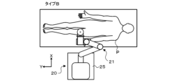
- FIG. 13 is an explanatory diagram showing the positional relationship between a type B human body and a robot.
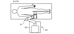
- FIG. 13 is an explanatory diagram showing the positional relationship between a type C human body and a robot.
- FIG. 13 is an explanatory diagram showing the positional relationship between a type D human body and a robot.
- FIG. 13 is an explanatory diagram showing the state of point sorting.
- FIG. 13 is an explanatory diagram showing the state of point sorting.
- FIG. 2 is an explanatory diagram for explaining a monitoring function.
- FIG. 1 is an external perspective view of the robot system 10 of this embodiment.
- FIG. 2 is a schematic diagram of the robot 20.
- FIGS. 3 and 4 are partial enlarged views of the robot 20 including the hand unit 60.
- FIG. 5 is a block diagram showing the electrical connections of the robot system 10.
- the front-to-back direction is the X-axis
- the left-to-right direction is the Y-axis
- the up-down direction is the Z-axis.
- the robot system 10 of this embodiment includes a robot 20 having a multi-joint robot arm 21, a foot switch 91, an ESR controller 92, a tablet terminal 93, and an emergency stop switch 94.
- the robot system 10 holds the ultrasonic probe 101 of the ultrasonic diagnostic device 100 at the tip of the robot arm 21, and controls the robot 20 to move while pressing the ultrasonic probe 101 against the surface of the human body, thereby making the ultrasonic diagnostic device 100 acquire ultrasonic echo images of the human body.
- the robot system 10 is used as an ultrasonic echo guide during surgery, such as catheter surgery.
- the operator (surgeon) who operates the catheter guide wire instructs the robot 20 to press the ultrasonic probe 101 against the surface of the human body (patient), and while recognizing the positional relationship between the tip of the guide wire and the blood vessel from the obtained ultrasonic echo image, advances the guide wire, thereby allowing the guide wire to accurately pass through the center of the occlusion or stenosis of the blood vessel.
- the operator manually operates the robot arm 21, and while checking the ultrasonic echo image acquired by placing the ultrasonic probe 101 held by the robot arm 21 against the patient, determines the points (images) to be reproduced during surgery and performs direct teaching to register them in the robot 20 (robot control device 80).
- the ultrasound diagnostic device 100 comprises an ultrasound probe 101 and an ultrasound diagnostic device main body 110 connected to the ultrasound probe 101 via a cable 102.
- the ultrasound diagnostic device main body 110 comprises an ultrasound diagnosis control unit 111 that controls the entire device, an image processing unit 112 that processes the received signal from the ultrasound probe 101 to generate an ultrasound echo image, an image display unit 113 that displays the ultrasound echo image, and various operation switches (not shown).
- the robot 20 includes a base 25, a robot arm 21 mounted on the base 25, a hand 60 attached to the tip of the robot arm 21, a height adjustment mechanism 45 that manually adjusts the height of the robot arm 21, a robot control device 80 that controls the robot arm 21, and an operation panel 90.
- casters 26 with stoppers are attached to the four corners of the back surface of the base 25.
- the robot 20 can be moved freely by the casters 26.
- locking parts 28 are provided at multiple points (e.g., three points) on the back surface of the base 25, which protrude vertically downward when a lever 27 is pressed down to lock (fix) the robot 20 so that it cannot move.
- the robot arm 21 is a seven-axis articulated arm, and as shown in Figures 1 and 2, has a first arm 22, a second arm 23, a base 24, a first arm driver 35, a second arm driver 36, a position holding device 37, a three-axis rotating mechanism 50, and a brake lever 65 (see Figure 4).
- the base end of the first arm 22 is connected to the base 24 via a first joint shaft 31 that extends in the vertical direction (Z-axis direction).
- the first arm driving device 35 includes a motor 35a, an encoder 35b, and an amplifier 35c.
- the rotation shaft of the motor 35a is connected to the first joint shaft 31 via a reduction gear (not shown).
- the first arm driving device 35 rotates (pivots) the first arm 22 along a horizontal plane (XY plane) around the first joint shaft 31 as a fulcrum by driving the first joint shaft 31 to rotate with the motor 35a.
- the encoder 35b is attached to the rotation shaft of the motor 35a and is configured as a rotary encoder that detects the amount of rotational displacement of the motor 35a.
- the amplifier 35c is a driving unit for driving the motor 35a by switching the switching element.
- the base end of the second arm 23 is connected to the tip end of the first arm 22 via a second joint shaft 32 extending in the vertical direction.
- the second arm driving device 36 includes a motor 36a, an encoder 36b, and an amplifier 36c.
- the rotating shaft of the motor 36a is connected to the second joint shaft 32 via a reduction gear (not shown).
- the second arm driving device 36 rotates (pivots) the second arm 23 along a horizontal plane around the second joint shaft 32 as a fulcrum by driving the second joint shaft 32 to rotate with the motor 36a.
- the encoder 36b is attached to the rotating shaft of the motor 36a and is configured as a rotary encoder that detects the amount of rotational displacement of the motor 36a.
- the amplifier 35c is a driving unit for driving the motor 35a by switching the switching element.
- the robot 20 has two arm postures: a right arm posture mode in which the robot arm 21 operates in a right arm posture, and a left arm posture mode in which the robot arm 21 operates in a left arm posture.
- the base 24 is provided so as to be movable up and down with respect to the base 25 by a lifting device 40 installed on the base 25.
- the lifting device 40 includes a first slider 41 fixed to the base 24, a first guide member 42 extending in the vertical direction to guide the movement of the first slider 41, a first ball screw shaft 43 (lifting shaft) extending in the vertical direction and screwed into a ball screw nut (not shown) fixed to the first slider 41, a motor 44a that rotates the first ball screw shaft 43, an encoder 44b (see FIG. 3), and an amplifier 44c that drives the motor 44a.
- the lifting device 40 moves the base 24 fixed to the first slider 41 up and down along the first guide member 42 by rotating the first ball screw shaft 43 with the motor 44a.
- the encoder 44b is configured as a linear encoder that detects the vertical position (lifted position) of the first slider 41 (base 24).
- the height adjustment mechanism 45 includes a second slider 46 fixed to the first guide member 42 of the lifting device 40, a second guide member 47 fixed to the base 25 and extending in the vertical direction to guide the movement of the second slider 46, a second ball screw shaft 48 (lifting shaft) extending in the vertical direction and screwed into a ball screw nut (not shown) fixed to the second slider 46, and a rotating handle 49 connected to the second ball screw shaft 48 via a power transmission mechanism (bevel gear).
- the height adjustment mechanism 45 moves the first guide member 42 of the lifting device 40 fixed to the second slider 46 up and down along the second guide member 47 by manually operating the rotating handle 49 to rotate the second ball screw shaft 48.
- the base end of the robot arm 21 is fixed to the base 24, which is supported by the first guide member 42. Therefore, the height of the robot arm 21 can be adjusted by moving the first guide member 42 up and down using the height adjustment mechanism 45. This allows the height of the robot arm 21 to be adjusted according to the height of a bed on which a patient for ultrasound diagnosis lies, for example.
- the three-axis rotating mechanism 50 is connected to the tip of the second arm 23 via the attitude-maintaining shaft 33 extending in the vertical direction.
- the three-axis rotating mechanism 50 includes a first rotation shaft 51, a second rotation shaft 52, and a third rotation shaft 53 that are perpendicular to one another, a first rotation device 55 that rotates the first rotation shaft 51, a second rotation device 56 that rotates the second rotation shaft 52, and a third rotation device 57 as a hand drive device that rotates the third rotation shaft 53 to which the hand portion 60 is connected.
- the first rotation shaft 51 is supported in an orthogonal position relative to the attitude-maintaining shaft 33.
- the second rotation shaft 52 is supported in an orthogonal position relative to the first rotation shaft 51.
- the third rotation shaft 53 is supported in an orthogonal position relative to the second rotation shaft 52.
- the first rotating device 55 has a motor 55a that rotates the first rotating shaft 51, an encoder 55b that is attached to the rotating shaft of the motor 55a and detects the amount of rotational displacement of the motor 55a, and an amplifier 55c that drives the motor 55a.
- the second rotating device 56 has a motor 56a that rotates the second rotating shaft 52, an encoder 56b that is attached to the rotating shaft of the motor 56a and detects the amount of rotational displacement of the motor 56a, and an amplifier 56c that drives the motor 56a.
- the third rotating device 57 has a motor 57a that rotates the third rotating shaft 53, an encoder 57b that is attached to the rotating shaft of the motor 57a and detects the amount of rotational displacement of the motor 57a, and an amplifier 57c that drives the motor 56a.
- the third rotation device 57 (hand drive device) includes a housing 54 to which the second rotation shaft 52 is connected and which rotatably supports the third rotation shaft 53 so that the third rotation shaft 53 extends in a direction perpendicular to the second rotation shaft 52, a motor 57c that rotates the third rotation shaft 53, a force sensor 68, etc.
- the housing 54 is a box-shaped member having a first surface 54b, a second surface 54t, a third surface 54r, and a fourth surface 54f that are connected in the circumferential direction.
- the second rotating shaft 52 is connected to the third surface 54r.
- the third rotating shaft 53 is rotatably supported on the housing 54 so as to extend outward from the first surface 54b perpendicular to the third surface 54r, and is driven to rotate by a motor 57a.
- the first surface 54b is the lower surface
- the second surface 54t is the upper surface
- the third surface 54r is the back surface
- the fourth surface 54f is the front surface.
- FIG. 1 the first surface 54b
- the second surface 54t is the upper surface
- the third surface 54r is the back surface
- the fourth surface 54f is the front surface.
- the second surface 54t (top surface) of the housing 54 is provided with an operating handle 66 that is held by the operator when the operator manually operates the ultrasound probe 101 held by the robot arm 21 during direct teaching, and a stop switch 67 that the operator can operate to temporarily stop the operation of the robot arm 21 when an unexpected operation occurs in the robot arm 21.
- the force sensor 68 is attached to the third rotation shaft 53 of the robot arm 21.
- the force sensor 68 transmits power from the motor 57a to the third rotation shaft 53 (hand end portion 60), and detects the force components acting in the axial directions of the X-axis, Y-axis, and Z-axis as external forces acting on the hand end portion 60 and the operating handle 66, as well as the torque components acting around the axes Ra, Rb, and Rc.
- the hand 60 is attached to the tip of the third rotating shaft 53.
- the hand 60 has a base 601, a holding part 602 that holds the ultrasonic probe 101 so as to be coaxial with the third rotating shaft 53, and a gripping part 603 that is a part that is held by the operator.
- the base 601 is a plate-shaped member and is detachably attached to the third rotating shaft 53 by a snap lock 64.
- the hand 60 (base 601) may be attached to the third rotating shaft 53 by other fixing devices (e.g., a ratchet-type fixing device, a screw, etc.).
- the holding part 602 has a holder provided on one surface of the base 601, and holds the ultrasonic probe 101 by the holder.
- the gripping part 603 is held by the operator when the operator moves the ultrasonic probe 101 held by the robot arm 21 by hand, for example, in direct teaching.
- the gripping portion 603 is provided on the surface of the base 601 opposite to the surface on which the holding portion 602 is provided, and is formed so as to protrude outward in a convex shape from the other surface.
- the gripping portion 603 is formed with a convex curved surface as shown in Figures 3 and 4, but it may be formed in any shape, such as a rod shape, a hemisphere shape, a rectangular parallelepiped shape, or a cube shape, as long as it is a shape that can be held by an operator.
- a direct teaching switch 61 is provided at the top of the convex portion (convex curved surface portion) of the gripping portion 603 to allow the operator to manually operate the robot arm 21 in direct teaching.
- the direct teaching switch 61 is configured as a three-position enable switch.
- One end of a cable 62 is connected to a terminal of the direct teaching switch 61.
- a cable guide 63 that guides one end of the cable 62 to the direct teaching switch 61 is fixed to the other surface of the base 601 of the hand 60, closer to the housing 54 than the grip 603.
- the other end of the cable 62 is connected to a wiring that runs from the housing 54 along the robot arm 21 to the robot control device 80.
- a connector 621 is provided at the other end of the cable 62, and is removably connected to a connector provided on the housing 54. Therefore, by unlocking the snap lock 64 and pulling out the connector 621, the hand 60 can be easily detached from the housing 54, improving maintainability.
- the robot 20 of this embodiment operates the robot arm 21 by a combination of translational motion in three directions, the X-axis direction, the Y-axis direction, and the Z-axis direction, by the first arm driving device 35, the second arm driving device 36, and the lifting device 40, and rotational motion in three directions, the X-axis direction Rb (pitching), the Y-axis direction (rolling) Ra, and the Z-axis direction (yawing) Rc, by the three-axis rotation mechanism 50.
- the robot 20 can move the ultrasonic probe 101 in each of the X-axis, Y-axis, and Z-axis directions (both forward and reverse directions) and rotate it around each of the Ra, Rb, and Rc axes (both forward and reverse rotation directions), as shown in FIG. 6.
- the attitude holding device 37 holds the attitude of the three-axis rotating mechanism 50 (the orientation of the first rotating shaft 51) in a constant orientation regardless of the orientation of the first arm 22 and the second arm 23.
- the attitude holding device 37 includes a motor 37a, an encoder 37b, and an amplifier 37c.
- the rotating shaft of the motor 37a is connected to the attitude holding shaft 33 via a reduction gear (not shown).
- the attitude holding device 37 sets a target rotation angle of the attitude holding shaft 33 based on the rotation angle of the first joint shaft 31 and the rotation angle of the second joint shaft 32 so that the axial direction of the first rotating shaft 51 is always in the left-right direction (X-axis direction), and drives and controls the motor 37a so that the attitude holding shaft 33 is at the target rotation angle. This makes it possible to control the translational motion in three directions and the rotational motion in three directions independently, making control easier.
- the brake lever 65 is a generally L-shaped member that extends downward (in the direction of extension of the attitude-maintaining shaft 33) from the three-axis rotating mechanism 50 and bends at an orthogonal direction at the end of the extension.
- Mechanical brakes e.g., disk brakes
- the mechanical brakes are attached to each axis of the robot arm 21 except for the horizontally rotating axis (first joint axis 31, second joint axis 32, and attitude-maintaining shaft 33), and the mechanical brakes are configured to be activated when the corresponding motor stops operating.
- the operator can release the mechanical brake by operating the brake lever 65 upward in the figure. This allows the operator to manually release the mechanical brake even if the power supply is cut off due to some abnormality in the robot 20, and to move the robot arm 21 to a safe position.
- the operation panel 90 is a touch panel display that displays various information related to the robot system 10 and allows various instructions to be input to the robot system 10.
- the operation panel 90 is installed on the top surface of the housing 29 that houses the lifting device 40 of the robot 20 and the robot control device 80.
- the foot switch 91 is a pedal switch that is turned on when the operator steps on it, and is connected to the robot control device 80 of the robot 20 via a cable.
- the foot switch 91 has four switches (a first switch 911, a second switch 912, a third switch 913, and a fourth switch 914) arranged horizontally.
- the ESR controller 92 is an operation controller that is operated by the operator while being held with both hands and pressed down, and is connected wirelessly to the robot control device 80 of the robot 20.
- the ESR controller 92 may also be connected to the robot control device 80 of the robot 20 by wire. In this embodiment, as shown in FIG.
- the ESR controller 92 has a directional key button 921 (up button, down button, left button, and right button) operated by the left thumb, four push buttons 922 (A button, B button, X button, and Y button) arranged in a diamond shape operated by the right thumb, L1 and L2 buttons 923 operated by the index finger and middle finger of the left hand, respectively, R1 and R2 buttons 924 operated by the index finger and middle finger of the right hand, respectively, and multiple push buttons 925 and 926 arranged between the directional key button 921 and the four push buttons 922.
- a directional key button 921 up button, down button, left button, and right button
- four push buttons 922 A button, B button, X button, and Y button
- L1 and L2 buttons 923 operated by the index finger and middle finger of the left hand, respectively
- R1 and R2 buttons 924 operated by the index finger and middle finger of the right hand, respectively
- multiple push buttons 925 and 926 arranged between the directional key button 921 and
- the tablet terminal 93 is equipped with a control device including a CPU, ROM, RAM, and storage (SSD), a touch panel display that displays various information and allows the operator to input operations, and a communication unit.
- the tablet terminal 93 is communicatively connected to the robot control device 80 of the robot 20 via wireless communication.
- the tablet terminal 93 has a remote desktop function that allows the operation panel 90 to be remotely operated from the tablet terminal 93 via wireless communication.
- the emergency stop switch 94 is a button that forcibly stops the robot 20 in the event of an emergency, and is connected to the robot control device 80 via a cable.
- the emergency stop switch 94 may also be provided on the robot arm 21.
- the robot control device 80 comprises a robot control unit 81, a monitoring unit 82, an IO unit 83, a communication unit 84, and a memory unit 85.
- the robot control unit 81 is configured as a processor including a CPU, ROM, RAM, peripheral circuits, etc.
- the monitoring unit 82 is configured as a one-chip microcomputer including a CPU, ROM, RAM, peripheral circuits, etc. The monitoring unit 82 may also be duplicated.
- the robot control unit 81 performs various processes related to the control of the robot arm 21 (motors 35a-37a, 44a, 55a-57a).
- the monitoring unit 82 monitors the status of each unit, such as the IO unit 83, communication unit 84, amplifiers 35c-37c, 44c, 55c-57c, encoders 35b-37b, 44b, 55b-57b, and a sensor unit including a direct teaching switch 61, etc.
- the IO unit 83 is an I/O port that inputs detection signals from the direct teaching switch 61, detection signals from the stop switch 67, operation signals from the operation panel 90, etc., and outputs display signals to the operation panel 90.
- the communication unit 84 communicates with the robot control device 80 and external devices (foot switch 91, ESR controller 92, tablet terminal 93, emergency stop switch 94, etc.) via wired or wireless means, and exchanges various signals and data.
- Each of the amplifiers 35c-37c, 44c, 55c-57c includes a motor control unit 71, a drive power supply unit 72, and an IO unit 73.
- the motor control unit 71 has switching elements, and controls the motors 35a-37a, 44a, 55a-57a by controlling the switching of the switching elements based on feedback signals from the encoders 35b-37b, 44b, 55b-57b, etc.
- the drive power supply unit 72 supplies the power required to drive the motors 35a-37a, 44a, 55a-57a.
- the IO unit 83 is an I/O port that inputs various signals such as position signals from the encoders 35b-37b, 44b, 55b-57b, current signals from current sensors that detect the current flowing through each of the motors 35a-37a, 44a, 55a-57a, and command signals (control signals) from the robot control unit 81 to each of the motors 35a-37a, 44a, 55a-57a.
- the robot 20 has three robot statuses: control off, control on, and robot on.
- Control off is a state in which the robot control unit 81 has stopped supplying power to the amplifiers 35c to 37c, 44c, and 55c to 57c, making the robot arm 21 (motor) uncontrollable.
- Control on is a state in which the robot control unit 81 is supplying power to the amplifiers 35c to 37c, 44c, and 55c to 57c, making the robot arm 21 controllable. In this state, it is possible to change the posture of the robot arm 21 by directly touching it.
- Robot on is a state in which the robot control unit 81, in the control on state, outputs a control signal to the amplifiers 35c to 37c, 44c, and 55c to 57c to control the robot arm 21.
- the robot status is changed based on the operator's instructions and based on the monitoring results of the monitoring unit 82.
- Figure 7 is an explanatory diagram explaining the modes through which the robot system 10 transitions from power-on to power-off.
- the robot control device 80 of the robot system 10 first executes a startup mode in which the system is prepared for use.
- pre-use inspection In the start-up mode, pre-use inspection, user selection/user setting, self-diagnosis, posture conversion, etc. are performed.
- images and explanations are used to present inspection points on the operation panel 90 to encourage the user to inspect the system before using it.
- the operation panel 90 accepts the selection of a user registered in advance and various settings for each user.
- the parameter setting function described later can be used to set the operating feel (assist force) when the user (operator) manually operates the robot arm 21 in direct teaching for each user.
- the posture change involves accepting a selection on the operation panel 90 between a right-arm posture mode in which the robot arm 21, including the horizontal joint arm (first arm 22, second arm 23), operates in a right-arm posture, or a left-arm posture mode in which the robot arm 21 operates in a left-arm posture, and automatically changing the posture of the robot arm 21 according to the selected posture mode.
- the robot control device 80 transitions to the operation mode.
- the modes available after the system has started up also include a maintenance mode and a setting mode. The mode transitions between the three modes occur when the operator operates the operation panel 90 or tablet terminal 93. Then, when an instruction to turn off the power is given, the robot control device 80 executes the shutdown mode, which performs a specified shutdown process, and then turns off the power.
- the operation panel 90 includes a "tablet connection start” button.
- the “tablet connection start” button When the operator touches the "tablet connection start” button on the operation panel 90, wireless connection between the tablet terminal 93 and the robot control device 80 is permitted. For this reason, when the operator wirelessly connects the tablet terminal 93 to the robot control device 80, it is necessary for the operator to approach close to the robot 20 and directly operate the operation panel 90.
- the tablet terminal 93 When the tablet terminal 93 is wirelessly connected to the robot control device 80, the same screen as that displayed on the operation panel 90 is displayed on the display of the tablet terminal 93 by the remote desktop function.
- the operator can remotely operate the operation panel 90 from a position away from the robot 20 by operating the tablet terminal 93.
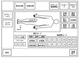
- the screen displayed on the operation panel 90 or the remotely connected tablet terminal 93 includes an "operation” button, a "maintenance” button, and a “setting” button, as shown in FIG. 8, and the operator can transition to any of the operation mode, maintenance mode, and setting mode by touching (operating) any of the three buttons.
- maintenance mode can only be used by maintenance personnel, and a password is required to switch modes.
- the operation mode is the mode used during surgery.
- the various functions of the operation mode include direct teaching, point registration, point display, point sorting, point deletion, point playback, interpolation movement, 90 degree rotation, fine adjustment, movement to storage position, movement to origin position, etc. These functions are executed by the operator operating the operation panel 90, tablet terminal 93, foot switch 91, ESR controller 92, etc.
- Direct teaching is a function that allows the operator to directly operate the robot arm 21 by gripping the gripping portion 603 of the hand portion 60 or the operating handle 66 and applying force, and generates an assist force from the motors of each axis in the direction of the force applied so that the operator can operate the robot arm 21 with less force.
- Direct teaching is performed only while the direct teaching switch 61 is on. When the direct teaching switch 61 is turned off, the motor assistance is stopped, making it difficult for the operator to manually operate the robot arm 21. Note that point regeneration, which will be described later, is performed with the direct teaching switch 61 turned off.
- point registration the operator manually operates the robot arm 21 in direct teaching, and while checking the ultrasound echo image acquired by placing the ultrasound probe 101 held by the robot arm 21 on the patient, determines and registers points (images) to be reproduced during surgery.
- the registered points include the position and orientation of the ultrasound probe 101 (X, Y, Z coordinate values and the angle values of Rb, Rb, Rc), the position of each axis of the robot arm 21 (angle values and elevation coordinate values), etc.
- Point registration can be performed by touching (operating) the "point record" button on the operation panel 90 or the remotely connected tablet terminal 93.
- point registration can also be performed by stepping on the foot switch 91 (for example, the first switch 911). This makes it possible to reliably perform point registration operations even if the operator manually operates the robot arm 21 and the operator's hands are occupied.
- the point display is a function that displays the registered points on the operation panel 90 or a remotely connected tablet terminal 93.
- the point display is a function that displays the registered points on the operation panel 90 or a remotely connected tablet terminal 93.
- the operable range of the ultrasound probe 101 is also displayed on the operation panel 90 or the tablet terminal 93.
- Point sorting is a function that rearranges the registered points.
- the order in which the points are played back is from the base of the patient's feet to the soles. For this reason, the robot control device 80 automatically rearranges the recorded points based on the conditions received from the user when changing posture in the startup mode. Details of point sorting will be described later.
- Point deletion is a function for deleting registered points.
- the points to be deleted can be selected individually or deleted all at once.
- the former operation is performed by touching (operating) the "Delete selected” button on the operation panel 90 or on the remotely connected tablet terminal 93, and the latter operation is performed by touching (operating) the "Delete all" button.
- Point replay is a function that replays registered points.
- point replay By executing point replay during surgery, ultrasonic echo images for each point are automatically acquired, and the surgeon can operate the catheter while viewing the images.
- the surgeon can move the point from the current point to the next point or the previous point by touching (operating) the operation panel 90 or the remotely connected tablet terminal 93, or by stepping on the foot switch 91.
- the surgeon can move the point from the current point to the next point by stepping on the third switch 913 of the foot switch 91, and can move from the current point to the previous point by stepping on the second switch 912 of the foot switch 91.
- the replay mode of point replay also includes interpolation movement and continuous movement.
- the robot control device 80 When continuous movement is selected, the robot control device 80 continues to operate while the operator is touching the operation panel 90 or stepping on the foot switch 91, and stops the robot arm 21 at that position when the touch or stepping is released. This allows the operator to stop the robot arm 21 at any point.
- Interpolation movement is a function that sets an arbitrary movement distance and moves the robot arm 21 (ultrasound probe 101) to that position. When an arbitrary movement distance is set, the position is calculated by automatic interpolation from registered points. Note that movement methods for point playback movement and interpolation movement include linear interpolation, joint interpolation, and circular interpolation. The operator can select one of the movement methods by operating the operation panel 90 or a remotely connected tablet terminal 93.
- the 90-degree rotation is a function that rotates the ultrasonic probe 101 by 90 degrees while maintaining the current posture of the robot arm 21.
- ultrasonic echo guidance in catheter surgery is performed by applying the long axis direction of the ultrasonic probe 101 to the direction of blood vessel progression.
- the uniaxial direction of the ultrasonic probe 101 is applied to the direction of blood vessel progression so that an ultrasonic echo image of a cross section in the width direction of the blood vessel is obtained to check whether the position of the catheter in the blood vessel is not displaced from the center of the blood vessel.
- the 90-degree rotation reproduces this series of operations.
- the ultrasonic probe 101 is rotated while being applied to the patient, the patient may feel pain or discomfort.
- the 90-degree rotation is performed by temporarily moving the ultrasonic probe 101 away from the patient's body surface, rotating the ultrasonic probe 101 by 90 degrees, and then contacting the ultrasonic probe 101 with the body surface, as shown in FIG. 9.
- the 90-degree rotation is performed by touching (operating) the "90-degree rotation" button on the operation panel 90 or the remotely connected tablet terminal 93, or by pressing the push button 925 on the ESR controller 92.
- the 90-degree rotation may be slightly off-angle as long as it changes the direction from the long axis to the short axis.
- the fine adjustment function allows fine position adjustment from the playback position by point playback. This is because even if the robot arm 21 is moved to a point registered by point playback, it rarely matches perfectly with the ultrasonic echo image acquired by direct teaching.
- the fine adjustment function can be performed individually for each of the X-axis, Y-axis, and Z-axis directions, and for each of the Y-axis Ra, X-axis Rb, and Z-axis Rc.
- the fine adjustment method includes a step operation that operates a preset step amount, and a continue operation that continues while a button is operated.
- the fine adjustment function can be performed by touching the corresponding button on the operation panel 90 or the remotely connected tablet terminal 93, or by pressing the corresponding button on the ESR controller 92.
- the operator can adjust to the + side of the X-axis direction by pressing the up button of the directional key buttons 921 operated by the left thumb, adjust to the - side of the X-axis direction by pressing the down button, adjust to the + side of the Y-axis direction by pressing the left button, and adjust to the - side of the Y-axis direction by pressing the right button.
- the operator can adjust to the + side of the Z-axis direction by pressing the L1 button of the L1 button operated by the index finger of the left hand and adjust to the - side of the Z-axis direction by pressing the L2 button.
- the operator can adjust to the + side of the Y-axis Ra by pressing the A button of the four diamond-shaped push buttons 922 operated by the right thumb, adjust to the - side of the Y-axis Ra by pressing the B button, adjust to the + side of the X-axis Rb by pressing the X button, and adjust to the - side of the X-axis Rb by pressing the Y button.
- the operator can adjust Rc around the Z axis to the + side by pressing the R1 button, which is operated with the index finger of the right hand, and R2 button, which is operated with the middle finger of the right hand, and can adjust Rc around the Z axis to the - side by pressing the R2 button.
- the ESR controller 92 also has an inversion function that inverts the positive and negative directions associated with each button for each set, with the X-axis and Rb around the X-axis, the Y-axis and Ra around the Y-axis, and the Z-axis and Rc around the Z-axis. This is because the direction of movement of the robot 20 seen by the operator changes, for example, when the operator operates the ESR controller 92 alongside the robot 20 and when the operator operates the ESR controller 92 in a position facing the robot 20.
- the inversion function is executed by pressing the push button 926 on the ESR controller 92 or by operating the operation panel 90 or a remotely connected tablet terminal 93.
- one of the foot switches 91 (e.g., the fourth switch 914) connected by wire to the robot control device 80 is provided with an enable button for enabling operation of the ESR controller 92, and the robot control device 80 only accepts operation of the ESR controller 92 within the range in which the foot switch 91 can be depressed.
- the movement to the storage position is a function that moves the robot arm 21 to a predetermined storage position (for example, a position where the robot arm 21 is folded to make the robot 20 compact).
- the movement to the origin position is a function that moves the robot arm 21 to a predetermined origin position (for example, a position where the robot arm 21 extends forward from the storage position and the tip of the ultrasound probe 101 is oriented to point straight down).
- the movement to the storage position is performed by touching (operating) the "storage position" button on the operation panel 90 or the remotely connected tablet terminal 93, and the movement to the origin position is performed by touching (operating) the "origin position" button on the operation panel 90 or the remotely connected tablet terminal 93.
- the maintenance mode is a mode that can only be used by maintenance personnel.
- the various functions of the maintenance mode include jog operation, status acquisition, regular inspection, and version management.
- the jog operation is a function that executes the operation of each axis of the robot arm 21, the reference operation of the hand, and the reference operation of the tip of the ultrasonic probe 101 by specifying any amount.
- the status acquisition is a function that can acquire the current state of the robot 20 (the angle of each axis of the robot arm 21, the position of the hand, the value of the force sensor 68, etc.).
- the regular inspection is a function that notifies that the time for inspection is approaching and encourages regular inspection of the device.
- the version management is a function that upgrades the software to the robot control device 80 via USB (Universal Serial Bus) in order to improve the functions of the system and deal with malfunctions.
- the setting mode is a mode in which various settings can be changed.
- the various functions of the setting mode include IO allocation setting, parameter setting, and user setting.
- the parameter setting is a function that allows you to change any parameter in this system.
- the parameter items that can be changed differ depending on the user level.
- the IO allocation setting is a function that allows you to change the allocation of functions to the foot switch 91 and the stop switch 67.
- the first switch 911, the second switch 912, the third switch 913, and the fourth switch 914 are assigned the following functions as the default settings for the foot switch 91: point registration, previous point in point regeneration, next point in point regeneration, and activation of the ESR controller 92, respectively.
- the allocation of each function such as point registration, previous point in point regeneration, next point, and activation of the ESR controller 92, can be changed to any of the first to fourth switches 911 to 914.
- the user setting has been described above.
- FIG. 12 is a flowchart showing an example of wireless connection confirmation processing executed by the robot control device 80.
- the robot control device 80 first determines whether the connection in progress flag F is set to a value of 0 (S100).
- the connection in progress flag F is a flag that is initially set to a value of 0 and is set to a value of 1 when a communication connection between the tablet terminal 93 and the communication unit 84 of the robot control device 80 is established.
- the robot control device 80 determines whether a connection start operation has been performed on the operation panel 90 (S102). The determination of whether a connection start operation has been performed is performed by determining whether the operator has touched (operated) the "tablet connection start” button (see FIG. 8) on the operation panel 90. When the robot control device 80 determines that a connection start operation has not been performed, it ends the wireless connection confirmation processing as it is. On the other hand, when the robot control device 80 determines that the "tablet connection start” button has been touched, it establishes a communication connection between the tablet terminal 93 and the communication unit 84 (S104), and then sets the connection flag F to a value of 1 (S106).
- the robot control device 80 permits a remote connection from the tablet terminal 93 (S108), and ends the wireless connection confirmation process.
- the tablet terminal 93 displays the same screen as the screen of the operation panel 90, and the operator can remotely operate the operation panel 90 by operating the tablet terminal 93. Since the operator can use the tablet terminal 93 in a place where the robot 20 is not visible, which may compromise safety, in this embodiment, in order to wirelessly connect the tablet terminal 93 to the robot control device 80, it is necessary to approach the robot 20 and operate the operation panel 80.
- the robot control device 80 determines whether or not a disconnection operation has been performed (S110). Whether or not a disconnection operation has been performed is determined by determining whether or not a "disconnect tablet connection" button on the operation panel 90 or on the remotely connected tablet terminal 93 has been touched (operated). If the robot control device 80 determines that a disconnection operation has been performed, it disconnects the communication connection with the tablet terminal 93 (S112), sets the connection in progress flag F to a value of 0 (S114), and ends the wireless connection confirmation process. Then, for example, the process returns to operation on the operation panel 90.
- the robot control device 80 acquires the radio wave intensity between the robot control device 80 and the tablet terminal 93 and determines whether the acquired radio wave intensity is equal to or greater than a threshold value (S116). If the robot control device 80 determines that the radio wave intensity is less than the threshold value, it disconnects the communication connection with the tablet terminal 93 (S112), sets the connection flag F to a value of 0 (S114), and ends the wireless connection confirmation process. This makes it possible to prevent the robot arm 21 from performing unexpected movements due to signal exchange between the robot control device 80 and the tablet terminal 93 in an unstable communication situation.
- the robot control device 80 determines whether the radio wave intensity is equal to or greater than the threshold value, it determines whether the communication connection with the tablet terminal 93 has been interrupted (S118). If the robot control device 80 determines that the communication connection has not been interrupted, it ends the connection confirmation process while maintaining the wireless connection state. On the other hand, when the robot control device 80 determines that the communication connection has been cut off, it transitions to a safe state (e.g., control off) (S120), sets the connection flag F to a value of 0 (S122), and ends the wireless connection confirmation process.
- a safe state e.g., control off
- FIG. 13 is a flowchart showing an example of the point sorting process executed by the robot control device 80.
- the robot control device 80 first acquires the posture type of the robot arm 21 relative to the patient (S200).
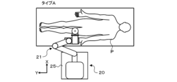
- the posture types include types A to D.
- Type A is a posture type in which the robot 20 is placed on the left hand side of the patient P and the robot arm 21 is operated in a left arm posture, as shown in FIG. 14A.
- Type B is a posture type in which the robot 20 is placed on the left hand side of the patient P and the robot arm 21 is operated in a right arm posture, as shown in FIG. 14B.
- Type C is a posture type in which the robot 20 is placed on the right hand side of the patient P and the robot arm 21 is operated in a left arm posture, as shown in FIG. 14C.
- Type D is a posture type in which the robot 20 is placed on the right hand side of the patient P and the robot arm 21 is operated in a right arm posture, as shown in FIG. 14D.
- the posture type is acquired by acquiring the posture type selected by the operator during posture conversion in the start-up mode.
- the robot control device 80 judges whether the acquired posture type is type A or type B (S202).
- the robot control device 80 judges that the posture type is type A or type B, it sorts the registered points in ascending order in the Y-axis direction (from right to left in FIG. 15) based on the Y-coordinate value of each point (S204), and ends the point sorting process.
- the robot control device 80 judges that the acquired posture type is type C or type D, it sorts the registered points in descending order in the Y-axis direction (from left to right in FIG. 16) based on the Y-coordinate value of each point (S206), and ends the point sorting process.
- the monitoring function of the monitoring unit 82 of the robot control device 80 will be described.
- the functions of the monitoring unit 82 include a monitoring function, a fault detection function, and a safety IO function.
- the robot control device 80 determines that an abnormality has occurred in any of the functions, it transitions the state of the robot 20 to a safe state (e.g., control off).
- the monitoring functions include amplifier encoder monitoring, amplifier current sensor monitoring, amplifier output voltage monitoring, input voltage monitoring, microcomputer power supply monitoring, microcomputer temperature monitoring, microcomputer failure monitoring, emergency stop signal monitoring, safety IO input signal monitoring, safety IO output signal monitoring, communication monitoring, and direct teaching switch monitoring.
- Amplifier encoder monitoring is used to determine failures in the encoders 35b-37b, 44b, and 55b-57b.
- Amplifier current sensor monitoring is used to determine failures in the current sensor that detects the output current to the motors 35a-37a, 44a, and 55a-57a.
- Amplifier output voltage monitoring is used to determine failures in the motor control unit 71 (switching element).
- Input voltage monitoring is used to monitor the voltage supplied to the robot control device 80 (main board).
- Microcomputer power start is used to monitor the voltage supplied to the microcomputer (robot control unit 81, monitoring unit 82).
- Microcomputer temperature monitoring is used to monitor the ambient temperature of the microcomputer.
- Microcomputer failure monitoring is used to determine failures in the microcomputer.
- Emergency stop signal monitoring is used to determine failures in the emergency stop switch 94.
- Safety IO input signal monitoring monitors input signals other than emergency stop signals that are input to the robot controller 80.
- Safety IO output signal monitoring monitors output signals that are output from the robot controller 80.
- Communication monitoring monitors communications in the communication unit 84.
- Direct teaching switch monitoring monitors failures of the direct teaching switch 61.
- the obstacle detection function includes a torque obstacle detection function, a speed obstacle detection function, a position obstacle detection function, and an external force obstacle detection function.
- the torque obstacle detection function detects a state in which a torque exceeding a set torque is output to each axis or hand of the robot arm 21.
- the speed obstacle detection function detects a state in which each axis or hand of the robot arm 21 operates at a speed exceeding a set speed.
- the position obstacle detection function detects a state in which each axis or hand of the robot arm 21 is positioned outside a set range.
- the external force obstacle detection function detects a state in which each axis or hand of the robot arm 21 is subjected to an external force exceeding an allowable range.
- the safety IO function includes an emergency stop function, a safety IO input function, and a safety IO output function.
- the emergency stop function detects the pressing of the emergency stop switch 94.
- the safety IO input function inputs input signals other than the emergency stop signal to the robot control device 80.
- the safety IO output function transmits an output signal according to the state of the robot 20 from the robot control device 80 to the outside (for example, a laser curtain or another robot).
- the ultrasonic probe 101 of the present embodiment corresponds to the ultrasonic probe of the present disclosure
- the robot arm 21 corresponds to the arm section
- the robot 20 corresponds to the robot
- the tablet terminal 93 corresponds to the wireless operation terminal.
- the ESR controller 92 corresponds to the operation controller.
- the foot switch 91 (first to fourth switches 911 to 914) corresponds to the foot switch.
- the operation mode corresponds to the first mode
- the maintenance mode corresponds to the second mode
- the setting mode corresponds to the third mode.
- the robot control device 80 corresponds to the processing unit.
- the robot 20 is configured as a seven-axis articulated robot capable of translational movement in three directions and rotational movement in three directions.
- the number of axes can be any number.
- the robot 20 may also be configured as a so-called vertical articulated robot or horizontal articulated robot.
- the wireless operation terminal is wirelessly connected to the robot, which reduces restrictions on the location where the wireless operation terminal can be used when performing ultrasonic echo guidance. As a result, it is possible to improve the convenience for the user when using the robot for ultrasonic echo guidance.
- the robot system of the present disclosure includes an operation controller that is manually operated by an operator and can instruct the robot to perform a predetermined operation
- the predetermined operation may include a fine adjustment operation for finely adjusting a point recorded by direct teaching, or a rotation operation for rotating the ultrasonic probe around an axis to change the angle of the ultrasonic probe pressed against the human body.
- the operation controller may include a plurality of operation buttons used to instruct the fine adjustment operation, each of which is associated with a different operation direction in the coordinate system of the robot, and may be capable of reversing the operation directions associated with each of the plurality of operation buttons. This can allow the fine adjustment operation to be performed correctly using the operation controller even if the positional relationship between the operator and the robot changes.
- the robot system of the present disclosure may further include at least one footswitch that is operated by the operator's footswitch, and the footswitch may include a switch for enabling the operation of the operation controller. This can prevent the operation controller from being operated in a location where the operator cannot see the robot, further improving safety.
- the robot system of the present disclosure may also include at least one footswitch that is operated by the operator's footswitch, and the footswitch may include a switch for instructing playback of a point recorded in direct teaching. In this way, ultrasonic echo guidance can be performed appropriately even if the operator's hands are occupied.
- the robot may have a first mode that allows direct teaching and playback of points recorded by direct teaching, a second mode for maintenance, and a third mode that allows various settings, and transitions may be made between the first mode, the second mode, and the third mode.
- a first mode that allows direct teaching and playback of points recorded by direct teaching
- a second mode for maintenance a second mode for maintenance
- a third mode that allows various settings, and transitions may be made between the first mode, the second mode, and the third mode.
- the robot system disclosed herein may include a processing unit that, when multiple points are recorded by direct teaching, sorts the multiple recorded points so that the multiple points are played back in a predetermined direction in order, and the processing unit may obtain a positional relationship between the robot and the human body, and change the predetermined direction based on the obtained positional relationship. In this way, the recorded points can be automatically rearranged even if the order in which the points are recorded does not match the order in which the points are played back.
- This disclosure can be used in the manufacturing industry for robotic systems used in ultrasonic echo guidance.
Landscapes
- Life Sciences & Earth Sciences (AREA)
- Health & Medical Sciences (AREA)
- Biomedical Technology (AREA)
- Biophysics (AREA)
- Nuclear Medicine, Radiotherapy & Molecular Imaging (AREA)
- Pathology (AREA)
- Radiology & Medical Imaging (AREA)
- Engineering & Computer Science (AREA)
- Physics & Mathematics (AREA)
- Heart & Thoracic Surgery (AREA)
- Medical Informatics (AREA)
- Molecular Biology (AREA)
- Surgery (AREA)
- Animal Behavior & Ethology (AREA)
- General Health & Medical Sciences (AREA)
- Public Health (AREA)
- Veterinary Medicine (AREA)
- Manipulator (AREA)
Abstract
This robot system comprises: a robot having an arm that is capable of holding an ultrasonic probe; and a wireless operation terminal that is wirelessly connected to the robot and is used by an operator when ultrasonic echo guidance is implemented using the robot.
Description
本明細書は、ロボットシステムについて開示する。
This specification discloses a robot system.
従来、この種のロボットシステムとしては、超音波プローブを保持して被検体の体表面に沿って超音波プローブを移動させるロボットアームと、ロボットアームによって超音波プローブを移動させるための指示軌跡情報を記憶する記憶部と、記憶された指示移動軌跡に従って超音波プローブを移動させるようにロボットアームの駆動を制御するロボットアーム制御部と、を備えるものが提案されている(例えば、特許文献1参照)。このロボットシステムでは、更に、ロボットアーム制御部とインターネット等のネットワークを介して接続され、ロボットアームに保持された超音波プローブの生体接触圧力情報を遠隔で検出すると共に、ロボットアームの駆動を遠隔から制御する触覚付き入力デバイスも備える。
Conventionally, a robot system of this type has been proposed that includes a robot arm that holds an ultrasound probe and moves the ultrasound probe along the body surface of a subject, a storage unit that stores instruction trajectory information for moving the ultrasound probe by the robot arm, and a robot arm control unit that controls the drive of the robot arm to move the ultrasound probe according to the stored instruction movement trajectory (see, for example, Patent Document 1). This robot system also includes a tactile input device that is connected to the robot arm control unit via a network such as the Internet, and that remotely detects living body contact pressure information of the ultrasound probe held by the robot arm and remotely controls the drive of the robot arm.
ロボットを超音波エコーガイドに用いるにあたり、操作者の利便性を向上させる上で、尚、改善の余地がある。
There is still room for improvement in terms of improving the convenience of the operator when using a robot for ultrasound echo guidance.
本開示は、ロボットを超音波エコーガイドに用いる場合の使用者の利便性を向上させることを主目的とする。
The primary objective of this disclosure is to improve the convenience of users when using a robot for ultrasound echo guidance.
本開示は、上述の主目的を達成するために以下の手段を採った。
This disclosure takes the following steps to achieve the above-mentioned primary objective:
本開示のロボットシステムは、
超音波プローブを保持可能なアーム部を有するロボットと、
前記ロボットに無線接続され、前記ロボットを用いた超音波エコーガイドの実施の際に操作者により使用される無線操作端末と、
を備えることを要旨とする。 The robot system of the present disclosure comprises:
a robot having an arm capable of holding an ultrasonic probe;
a wireless operation terminal that is wirelessly connected to the robot and is used by an operator when performing ultrasonic echo guidance using the robot;
The gist of the project is to provide the following:
この本開示のロボットシステムでは、無線操作端末がロボットに無線接続されて用いられるため、超音波エコーガイドの実施に際して無線操作端末を使用する場所に対する制約を軽減することができる。この結果、ロボットを超音波エコーガイドに用いる場合の使用者の利便性を向上させることができる。
In the robot system disclosed herein, the wireless operation terminal is wirelessly connected to the robot, which reduces restrictions on the location where the wireless operation terminal can be used when performing ultrasonic echo guidance. As a result, it is possible to improve the convenience for the user when using the robot for ultrasonic echo guidance.
次に、本開示を実施するための形態について図面を参照しながら説明する。
Next, the form for implementing this disclosure will be explained with reference to the drawings.
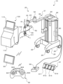
図1は、本実施形態のロボットシステム10の外観斜視図である。図2は、ロボット20の概略構成図である。図3および図4は、手先部60を含むロボット20の部分拡大図である。図5は、ロボットシステム10の電気的な接続関係を示すブロック図である。なお、図1中、前後方向がX軸であり、左右方向がY軸方向であり、上下方向がZ軸方向である。
FIG. 1 is an external perspective view of the robot system 10 of this embodiment. FIG. 2 is a schematic diagram of the robot 20. FIGS. 3 and 4 are partial enlarged views of the robot 20 including the hand unit 60. FIG. 5 is a block diagram showing the electrical connections of the robot system 10. In FIG. 1, the front-to-back direction is the X-axis, the left-to-right direction is the Y-axis, and the up-down direction is the Z-axis.
本実施形態のロボットシステム10は、図1~図5に示すように、多関節のロボットアーム21を有するロボット20と、フットスイッチ91と、ESRコントローラ92と、タブレット端末93と、非常停止スイッチ94と、を備える。
As shown in Figures 1 to 5, the robot system 10 of this embodiment includes a robot 20 having a multi-joint robot arm 21, a foot switch 91, an ESR controller 92, a tablet terminal 93, and an emergency stop switch 94.
ロボットシステム10は、図1~図4に示すように、ロボットアーム21の手先に超音波診断装置100の超音波プローブ101を保持し、超音波プローブ101を人体の体表面に押し当てて移動するようにロボット20を制御することにより、超音波診断装置100に人体の超音波エコー画像を取得させる。ロボットシステム10は、例えばカテーテル手術などの手術時の超音波エコーガイドとして用いられる。カテーテルのガイドワイヤを操作する操作者(術者)は、ロボット20に指示して超音波プローブ101を人体(患者)の体表面に押し当て、得られる超音波エコー画像からガイドワイヤの先端と血管との位置関係を認識しながら、ガイドワイヤを進めることで、ガイドワイヤを正確に血管の閉塞部位や狭窄部位の中央を通すことができる。操作者は、事前準備として、ロボットアーム21を手動操作し、ロボットアーム21に保持された超音波プローブ101を患者に当てて取得される超音波エコー画像を確認しつつ、手術中に再現したいポイント(画像)を決定してロボット20(ロボット制御装置80)に登録するダイレクトティーチングを行なう。
As shown in Figs. 1 to 4, the robot system 10 holds the ultrasonic probe 101 of the ultrasonic diagnostic device 100 at the tip of the robot arm 21, and controls the robot 20 to move while pressing the ultrasonic probe 101 against the surface of the human body, thereby making the ultrasonic diagnostic device 100 acquire ultrasonic echo images of the human body. The robot system 10 is used as an ultrasonic echo guide during surgery, such as catheter surgery. The operator (surgeon) who operates the catheter guide wire instructs the robot 20 to press the ultrasonic probe 101 against the surface of the human body (patient), and while recognizing the positional relationship between the tip of the guide wire and the blood vessel from the obtained ultrasonic echo image, advances the guide wire, thereby allowing the guide wire to accurately pass through the center of the occlusion or stenosis of the blood vessel. As a preliminary step, the operator manually operates the robot arm 21, and while checking the ultrasonic echo image acquired by placing the ultrasonic probe 101 held by the robot arm 21 against the patient, determines the points (images) to be reproduced during surgery and performs direct teaching to register them in the robot 20 (robot control device 80).
超音波診断装置100は、図1に示すように、超音波プローブ101と、超音波プローブ101とケーブル102を介して接続された超音波診断装置本体110と、を備える。超音波診断装置本体110は、図5に示すように、装置全体の制御を司る超音波診断制御部111と、超音波プローブ101からの受信信号を処理して超音波エコー画像を生成する画像処理部112と、超音波エコー画像を表示する画像表示部113と、各種操作スイッチ(図示せず)と、を備える。
As shown in FIG. 1, the ultrasound diagnostic device 100 comprises an ultrasound probe 101 and an ultrasound diagnostic device main body 110 connected to the ultrasound probe 101 via a cable 102. As shown in FIG. 5, the ultrasound diagnostic device main body 110 comprises an ultrasound diagnosis control unit 111 that controls the entire device, an image processing unit 112 that processes the received signal from the ultrasound probe 101 to generate an ultrasound echo image, an image display unit 113 that displays the ultrasound echo image, and various operation switches (not shown).
ロボット20は、図1,図2に示すように、基台25と、基台25上に設置されたロボットアーム21と、ロボットアーム21の先端部に取り付けられた手先部60と、手動操作によりロボットアーム21の高さを調整する高さ調整機構45と、ロボットアーム21を制御するロボット制御装置80と、操作パネル90と、を備える。
As shown in Figures 1 and 2, the robot 20 includes a base 25, a robot arm 21 mounted on the base 25, a hand 60 attached to the tip of the robot arm 21, a height adjustment mechanism 45 that manually adjusts the height of the robot arm 21, a robot control device 80 that controls the robot arm 21, and an operation panel 90.
基台25の裏面の四隅には、図1,図2に示すように、ストッパ付きのキャスター26が取り付けられている。ロボット20は、キャスター26により自由に移動させることが可能である。また、基台25の裏面の複数箇所(例えば3箇所)には、レバー27を押し下げることにより鉛直下方向に突出してロボット20を移動不能にロック(固定)するロック部28が設けられている。
As shown in Figures 1 and 2, casters 26 with stoppers are attached to the four corners of the back surface of the base 25. The robot 20 can be moved freely by the casters 26. In addition, locking parts 28 are provided at multiple points (e.g., three points) on the back surface of the base 25, which protrude vertically downward when a lever 27 is pressed down to lock (fix) the robot 20 so that it cannot move.
ロボットアーム21は、本実施形態では、7軸の多関節アームであり、図1,図2に示すように、第1アーム22と第2アーム23とベース24と第1アーム駆動装置35と第2アーム駆動装置36と姿勢保持装置37と回転3軸機構50とブレーキレバー65(図4参照)とを有する。
In this embodiment, the robot arm 21 is a seven-axis articulated arm, and as shown in Figures 1 and 2, has a first arm 22, a second arm 23, a base 24, a first arm driver 35, a second arm driver 36, a position holding device 37, a three-axis rotating mechanism 50, and a brake lever 65 (see Figure 4).
第1アーム22の基端部は、上下方向(Z軸方向)に延在する第1関節軸31を介してベース24に連結されている。第1アーム駆動装置35は、モータ35aとエンコーダ35bとアンプ35cとを備える。モータ35aの回転軸は、図示しない減速機を介して第1関節軸31に接続されている。第1アーム駆動装置35は、モータ35aにより第1関節軸31を回転駆動することにより、第1関節軸31を支点に第1アーム22を水平面(XY平面)に沿って回動(旋回)させる。エンコーダ35bは、モータ35aの回転軸に取り付けられ、モータ35aの回転変位量を検出するロータリエンコーダとして構成される。アンプ35cは、スイッチング素子のスイッチングによりモータ35aを駆動するための駆動部である。
The base end of the first arm 22 is connected to the base 24 via a first joint shaft 31 that extends in the vertical direction (Z-axis direction). The first arm driving device 35 includes a motor 35a, an encoder 35b, and an amplifier 35c. The rotation shaft of the motor 35a is connected to the first joint shaft 31 via a reduction gear (not shown). The first arm driving device 35 rotates (pivots) the first arm 22 along a horizontal plane (XY plane) around the first joint shaft 31 as a fulcrum by driving the first joint shaft 31 to rotate with the motor 35a. The encoder 35b is attached to the rotation shaft of the motor 35a and is configured as a rotary encoder that detects the amount of rotational displacement of the motor 35a. The amplifier 35c is a driving unit for driving the motor 35a by switching the switching element.
第2アーム23の基端部は、上下方向に延在する第2関節軸32を介して第1アーム22の先端部に連結されている。第2アーム駆動装置36は、モータ36aとエンコーダ36bとアンプ36cとを備える。モータ36aの回転軸は、図示しない減速機を介して第2関節軸32に接続されている。第2アーム駆動装置36は、モータ36aにより第2関節軸32を回転駆動することにより、第2関節軸32を支点に第2アーム23を水平面に沿って回動(旋回)させる。エンコーダ36bは、モータ36aの回転軸に取り付けられ、モータ36aの回転変位量を検出するロータリエンコーダとして構成される。アンプ35cは、スイッチング素子のスイッチングによりモータ35aを駆動するための駆動部である。
The base end of the second arm 23 is connected to the tip end of the first arm 22 via a second joint shaft 32 extending in the vertical direction. The second arm driving device 36 includes a motor 36a, an encoder 36b, and an amplifier 36c. The rotating shaft of the motor 36a is connected to the second joint shaft 32 via a reduction gear (not shown). The second arm driving device 36 rotates (pivots) the second arm 23 along a horizontal plane around the second joint shaft 32 as a fulcrum by driving the second joint shaft 32 to rotate with the motor 36a. The encoder 36b is attached to the rotating shaft of the motor 36a and is configured as a rotary encoder that detects the amount of rotational displacement of the motor 36a. The amplifier 35c is a driving unit for driving the motor 35a by switching the switching element.
本実施形態では、第1アーム22と第2アーム23は、水平関節アームを構成する。このため、ロボット20は、腕姿勢として、ロボットアーム21を右腕姿勢で動作させる右腕姿勢モードと、ロボットアーム21を左腕姿勢で動作させる左腕姿勢モードと、を有する。
In this embodiment, the first arm 22 and the second arm 23 form a horizontal joint arm. Therefore, the robot 20 has two arm postures: a right arm posture mode in which the robot arm 21 operates in a right arm posture, and a left arm posture mode in which the robot arm 21 operates in a left arm posture.
ベース24は、図2に示すように、基台25上に設置された昇降装置40により、基台25に対して昇降可能に設けられている。昇降装置40は、ベース24に固定された第1スライダ41と、上下方向に延出して第1スライダ41の移動をガイドする第1ガイド部材42と、上下方向に延出すると共に第1スライダ41に固定されたボールねじナット(図示せず)に螺合される第1ボールねじ軸43(昇降軸)と、第1ボールねじ軸43を回転駆動するモータ44aと、エンコーダ44b(図3参照)と、モータ44aを駆動するアンプ44cと、を備える。昇降装置40は、モータ44aにより第1ボールねじ軸43を回転駆動することにより、第1スライダ41に固定されたベース24を第1ガイド部材42に沿って上下に移動させる。エンコーダ44bは、第1スライダ41(ベース24)の上下方向における位置(昇降位置)を検出するリニアエンコーダとして構成される。
2, the base 24 is provided so as to be movable up and down with respect to the base 25 by a lifting device 40 installed on the base 25. The lifting device 40 includes a first slider 41 fixed to the base 24, a first guide member 42 extending in the vertical direction to guide the movement of the first slider 41, a first ball screw shaft 43 (lifting shaft) extending in the vertical direction and screwed into a ball screw nut (not shown) fixed to the first slider 41, a motor 44a that rotates the first ball screw shaft 43, an encoder 44b (see FIG. 3), and an amplifier 44c that drives the motor 44a. The lifting device 40 moves the base 24 fixed to the first slider 41 up and down along the first guide member 42 by rotating the first ball screw shaft 43 with the motor 44a. The encoder 44b is configured as a linear encoder that detects the vertical position (lifted position) of the first slider 41 (base 24).
高さ調整機構45は、図2に示すように、昇降装置40の第1ガイド部材42に固定された第2スライダ46と、基台25に固定されると共に上下方向に延出して第2スライダ46の移動をガイドする第2ガイド部材47と、上下方向に延出すると共に第2スライダ46に固定されたボールねじナット(図示せず)に螺合される第2ボールねじ軸48(昇降軸)と、動力伝達機構(傘歯車)を介して第2ボールねじ軸48に連結された回転ハンドル49と、を備える。高さ調整機構45は、回転ハンドル49の手動操作により第2ボールねじ軸48を回転駆動することにより、第2スライダ46に固定された昇降装置40の第1ガイド部材42を第2ガイド部材47に沿って上下に移動させる。ロボットアーム21の基端は、ベース24に固定され、当該ベース24は、第1ガイド部材42に支持されているから、高さ調整機構45により第1ガイド部材42を上下に移動させることで、ロボットアーム21の高さを調整することができる。これにより、例えば、超音波診断の患者が横たわるベッドの高さに応じてロボットアーム21の高さを調整することができる。
2, the height adjustment mechanism 45 includes a second slider 46 fixed to the first guide member 42 of the lifting device 40, a second guide member 47 fixed to the base 25 and extending in the vertical direction to guide the movement of the second slider 46, a second ball screw shaft 48 (lifting shaft) extending in the vertical direction and screwed into a ball screw nut (not shown) fixed to the second slider 46, and a rotating handle 49 connected to the second ball screw shaft 48 via a power transmission mechanism (bevel gear). The height adjustment mechanism 45 moves the first guide member 42 of the lifting device 40 fixed to the second slider 46 up and down along the second guide member 47 by manually operating the rotating handle 49 to rotate the second ball screw shaft 48. The base end of the robot arm 21 is fixed to the base 24, which is supported by the first guide member 42. Therefore, the height of the robot arm 21 can be adjusted by moving the first guide member 42 up and down using the height adjustment mechanism 45. This allows the height of the robot arm 21 to be adjusted according to the height of a bed on which a patient for ultrasound diagnosis lies, for example.
回転3軸機構50は、図1,図2に示すように、上下方向に延在する姿勢保持用軸33を介して第2アーム23の先端部に連結されている。回転3軸機構50は、互いに直交する第1回転軸51,第2回転軸52および第3回転軸53と、第1回転軸51を回転させる第1回転装置55と、第2回転軸52を回転させる第2回転装置56と、手先部60が連結される第3回転軸53を回転させる手先駆動装置としての第3回転装置57と、を備える。第1回転軸51は、姿勢保持用軸33に対して直交姿勢で支持されている。第2回転軸52は、第1回転軸51に対して直交姿勢で支持されている。第3回転軸53は、第2回転軸52に対して直交姿勢で支持されている。第1回転装置55は、第1回転軸51を回転駆動するモータ55aと、モータ55aの回転軸に取り付けられモータ55aの回転変位量を検出するエンコーダ55bと、モータ55aを駆動するアンプ55cと、を有する。第2回転装置56は、第2回転軸52を回転駆動するモータ56aと、モータ56aの回転軸に取り付けられモータ56aの回転変位量を検出するエンコーダ56bと、モータ56aを駆動するアンプ56cと、を有する。第3回転装置57は、第3回転軸53を回転駆動するモータ57aと、モータ57aの回転軸に取り付けられモータ57aの回転変位量を検出するエンコーダ57bと、モータ56aを駆動するアンプ57cと、を有する。
As shown in Figs. 1 and 2, the three-axis rotating mechanism 50 is connected to the tip of the second arm 23 via the attitude-maintaining shaft 33 extending in the vertical direction. The three-axis rotating mechanism 50 includes a first rotation shaft 51, a second rotation shaft 52, and a third rotation shaft 53 that are perpendicular to one another, a first rotation device 55 that rotates the first rotation shaft 51, a second rotation device 56 that rotates the second rotation shaft 52, and a third rotation device 57 as a hand drive device that rotates the third rotation shaft 53 to which the hand portion 60 is connected. The first rotation shaft 51 is supported in an orthogonal position relative to the attitude-maintaining shaft 33. The second rotation shaft 52 is supported in an orthogonal position relative to the first rotation shaft 51. The third rotation shaft 53 is supported in an orthogonal position relative to the second rotation shaft 52. The first rotating device 55 has a motor 55a that rotates the first rotating shaft 51, an encoder 55b that is attached to the rotating shaft of the motor 55a and detects the amount of rotational displacement of the motor 55a, and an amplifier 55c that drives the motor 55a. The second rotating device 56 has a motor 56a that rotates the second rotating shaft 52, an encoder 56b that is attached to the rotating shaft of the motor 56a and detects the amount of rotational displacement of the motor 56a, and an amplifier 56c that drives the motor 56a. The third rotating device 57 has a motor 57a that rotates the third rotating shaft 53, an encoder 57b that is attached to the rotating shaft of the motor 57a and detects the amount of rotational displacement of the motor 57a, and an amplifier 57c that drives the motor 56a.
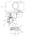
第3回転装置57(手先駆動装置)は、第2回転軸52が連結されると共に第2回転軸52に対して直交方向に延出するように第3回転軸53を回転可能に支持する筐体54や、第3回転軸53を回転駆動するモータ57c、力覚センサ68等を備える。
The third rotation device 57 (hand drive device) includes a housing 54 to which the second rotation shaft 52 is connected and which rotatably supports the third rotation shaft 53 so that the third rotation shaft 53 extends in a direction perpendicular to the second rotation shaft 52, a motor 57c that rotates the third rotation shaft 53, a force sensor 68, etc.
筐体54は、図3に示すように、それぞれ周方向につながる第1面54b、第2面54t、第3面54rおよび第4面54fを有する箱形の部材である。第2回転軸52は、第3面54rに連結される。第3回転軸53は、第3面54rに対して直交する第1面54bから外方へ延出するように筐体54に対して回転可能に支持され、モータ57aにより回転駆動される。ここで、ロボットアーム21が後述する原点位置に位置した状態(図2に示す状態)において、第1面54bは下面となり、第2面54tは上面となり、第3面54rは背面となり、第4面54fは前面となる。筐体54の第2面54t(上面)には、図3に示すように、ダイレクトティーチングにおいて、ロボットアーム21に保持された超音波プローブ101を操作者が手動操作する際に、操作者により把持される操作ハンドル66や、ロボットアーム21に予期しない動作が発生した際に操作者の操作によりロボットアーム21の動作を一時的に停止させるための停止スイッチ67が配置される。
As shown in Figure 3, the housing 54 is a box-shaped member having a first surface 54b, a second surface 54t, a third surface 54r, and a fourth surface 54f that are connected in the circumferential direction. The second rotating shaft 52 is connected to the third surface 54r. The third rotating shaft 53 is rotatably supported on the housing 54 so as to extend outward from the first surface 54b perpendicular to the third surface 54r, and is driven to rotate by a motor 57a. Here, when the robot arm 21 is positioned at the origin position described below (the state shown in Figure 2), the first surface 54b is the lower surface, the second surface 54t is the upper surface, the third surface 54r is the back surface, and the fourth surface 54f is the front surface. As shown in FIG. 3, the second surface 54t (top surface) of the housing 54 is provided with an operating handle 66 that is held by the operator when the operator manually operates the ultrasound probe 101 held by the robot arm 21 during direct teaching, and a stop switch 67 that the operator can operate to temporarily stop the operation of the robot arm 21 when an unexpected operation occurs in the robot arm 21.
力覚センサ68は、ロボットアーム21の第3回転軸53に取り付けられる。力覚センサ68は、モータ57aからの動力を第3回転軸53(手先部60)に伝達すると共に、手先部60や操作ハンドル66に加わる外力としてX軸,Y軸およびZ軸の各軸方向に作用する力成分とRa,RbおよびRcの各軸周りに作用するトルク成分とを検出する。
The force sensor 68 is attached to the third rotation shaft 53 of the robot arm 21. The force sensor 68 transmits power from the motor 57a to the third rotation shaft 53 (hand end portion 60), and detects the force components acting in the axial directions of the X-axis, Y-axis, and Z-axis as external forces acting on the hand end portion 60 and the operating handle 66, as well as the torque components acting around the axes Ra, Rb, and Rc.
手先部60は、第3回転軸53の先端部に取り付けられる。手先部60は、基部601と、第3回転軸53と同軸になるように超音波プローブ101を保持する保持部602と、操作者により把持される部分である把持部603と、を有する。基部601は、プレート状の部材であり、パッチン錠64により第3回転軸53に対して着脱可能に取り付けられている。なお、手先部60(基部601)は、他の固定具(例えば、ラチェット式固定具や、ねじ等)により第3回転軸53に取り付けられてもよい。保持部602は、基部601の一方の表面に設けられた保持具を有し、当該保持具により超音波プローブ101を保持する。把持部603は、例えば、ダイレクトティーチングにおいて、ロボットアーム21に保持された超音波プローブ101を操作者が手で動かす際に、当該操作者により把持される。把持部603は、基部601の保持部602が設けられた一方の表面とは反対側の他方の表面に設けられ、当該他方の表面から外側に凸状に突出するように形成されている。本実施形態では、把持部603は、図3,図4に示すように、凸曲面により形成されるが、操作者が把持可能な形状であれば、例えば棒状や半球状、直方体状、立方体状など如何なる形状により形成されてもよい。また、把持部603における凸状部(凸曲面部)の頂部には、ダイレクトティーチングにおいて操作者によるロボットアーム21の手動操作を許可するためのダイレクトティーチングスイッチ61が設けられている。
The hand 60 is attached to the tip of the third rotating shaft 53. The hand 60 has a base 601, a holding part 602 that holds the ultrasonic probe 101 so as to be coaxial with the third rotating shaft 53, and a gripping part 603 that is a part that is held by the operator. The base 601 is a plate-shaped member and is detachably attached to the third rotating shaft 53 by a snap lock 64. The hand 60 (base 601) may be attached to the third rotating shaft 53 by other fixing devices (e.g., a ratchet-type fixing device, a screw, etc.). The holding part 602 has a holder provided on one surface of the base 601, and holds the ultrasonic probe 101 by the holder. The gripping part 603 is held by the operator when the operator moves the ultrasonic probe 101 held by the robot arm 21 by hand, for example, in direct teaching. The gripping portion 603 is provided on the surface of the base 601 opposite to the surface on which the holding portion 602 is provided, and is formed so as to protrude outward in a convex shape from the other surface. In this embodiment, the gripping portion 603 is formed with a convex curved surface as shown in Figures 3 and 4, but it may be formed in any shape, such as a rod shape, a hemisphere shape, a rectangular parallelepiped shape, or a cube shape, as long as it is a shape that can be held by an operator. In addition, a direct teaching switch 61 is provided at the top of the convex portion (convex curved surface portion) of the gripping portion 603 to allow the operator to manually operate the robot arm 21 in direct teaching.
ダイレクトティーチングスイッチ61は、本実施形態では、3ポジションのイネーブルスイッチとして構成される。ダイレクトティーチングスイッチ61の端子には、ケーブル62の一端が接続される。手先部60の基部601における上記他方の表面であって把持部603よりも筐体54側には、ケーブル62の一端をダイレクトティーチングスイッチ61に導くケーブルガイド63が固定されている。ケーブル62の他端は、筐体54からロボットアーム21に沿ってロボット制御装置80につながる配線と接続される。本実施形態では、ケーブル62の他端には、コネクタ621が設けられており、筐体54に設けられたコネクタに対して抜き差し可能に接続される。このため、パッチン錠64を解錠すると共にコネクタ621を引き抜くことで、筐体54から手先部60を容易に切り離すことができ、メンテナンス性を向上させることができる。
In this embodiment, the direct teaching switch 61 is configured as a three-position enable switch. One end of a cable 62 is connected to a terminal of the direct teaching switch 61. A cable guide 63 that guides one end of the cable 62 to the direct teaching switch 61 is fixed to the other surface of the base 601 of the hand 60, closer to the housing 54 than the grip 603. The other end of the cable 62 is connected to a wiring that runs from the housing 54 along the robot arm 21 to the robot control device 80. In this embodiment, a connector 621 is provided at the other end of the cable 62, and is removably connected to a connector provided on the housing 54. Therefore, by unlocking the snap lock 64 and pulling out the connector 621, the hand 60 can be easily detached from the housing 54, improving maintainability.
本実施形態のロボット20は、第1アーム駆動装置35と第2アーム駆動装置36と昇降装置40とによるX軸方向,Y軸方向およびZ軸方向の3方向の並進運動と、回転3軸機構50によるX軸回りRb(ピッチング),Y軸回り(ローリング)RaおよびZ軸回り(ヨーイング)Rcの3方向の回転運動との組み合わせにより、ロボットアーム21を動作させる。これにより、ロボット20は、図6に示すように、超音波プローブ101をX軸,Y軸およびZ軸の各軸方向(正逆両方向)に移動させると共にRa,RbおよびRcの各軸周り(正逆両回転方向)に回転させることができる。
The robot 20 of this embodiment operates the robot arm 21 by a combination of translational motion in three directions, the X-axis direction, the Y-axis direction, and the Z-axis direction, by the first arm driving device 35, the second arm driving device 36, and the lifting device 40, and rotational motion in three directions, the X-axis direction Rb (pitching), the Y-axis direction (rolling) Ra, and the Z-axis direction (yawing) Rc, by the three-axis rotation mechanism 50. As a result, the robot 20 can move the ultrasonic probe 101 in each of the X-axis, Y-axis, and Z-axis directions (both forward and reverse directions) and rotate it around each of the Ra, Rb, and Rc axes (both forward and reverse rotation directions), as shown in FIG. 6.
姿勢保持装置37は、第1アーム22および第2アーム23の姿勢によらず回転3軸機構50の姿勢(第1回転軸51の向き)を一定の向きに保持するものである。姿勢保持装置37は、モータ37aとエンコーダ37bとアンプ37cとを備える。モータ37aの回転軸は、図示しない減速機を介して姿勢保持用軸33に接続されている。姿勢保持装置37は、第1回転軸51の軸方向が常時、左右方向(X軸方向)となるように第1関節軸31の回転角度と第2関節軸32の回転角度とに基づいて姿勢保持用軸33の目標回転角度を設定し、姿勢保持用軸33が目標回転角度となるようにモータ37aを駆動制御する。これにより、3方向の並進運動の制御と3方向の回転運動の制御とをそれぞれ独立して行なうことが可能となり、制御が容易となる。
The attitude holding device 37 holds the attitude of the three-axis rotating mechanism 50 (the orientation of the first rotating shaft 51) in a constant orientation regardless of the orientation of the first arm 22 and the second arm 23. The attitude holding device 37 includes a motor 37a, an encoder 37b, and an amplifier 37c. The rotating shaft of the motor 37a is connected to the attitude holding shaft 33 via a reduction gear (not shown). The attitude holding device 37 sets a target rotation angle of the attitude holding shaft 33 based on the rotation angle of the first joint shaft 31 and the rotation angle of the second joint shaft 32 so that the axial direction of the first rotating shaft 51 is always in the left-right direction (X-axis direction), and drives and controls the motor 37a so that the attitude holding shaft 33 is at the target rotation angle. This makes it possible to control the translational motion in three directions and the rotational motion in three directions independently, making control easier.
ブレーキレバー65は、図4に示すように、回転3軸機構50から図中、下方向(姿勢保持用軸33の延在方向)に延出すると共に延出端において直交方向に屈曲する略L字状の部材である。ロボットアーム21には、水平旋回する軸(第1関節軸31,第2関節軸32および姿勢保持用軸33)を除いた各軸に対して機械ブレーキ(例えば、ディスクブレーキ)が取り付けられており、当該機械ブレーキは、対応するモータの動作の停止により作動するように構成されている。操作者は、ブレーキレバー65を図中、上方向に操作することで、機械ブレーキの作動を解除することができる。これにより、ロボット20の何らかの異常により電源が遮断されても、操作者は、機械ブレーキを手動により解除することができ、ロボットアーム21を動かして安全な位置に退避させることが可能となる。
As shown in FIG. 4, the brake lever 65 is a generally L-shaped member that extends downward (in the direction of extension of the attitude-maintaining shaft 33) from the three-axis rotating mechanism 50 and bends at an orthogonal direction at the end of the extension. Mechanical brakes (e.g., disk brakes) are attached to each axis of the robot arm 21 except for the horizontally rotating axis (first joint axis 31, second joint axis 32, and attitude-maintaining shaft 33), and the mechanical brakes are configured to be activated when the corresponding motor stops operating. The operator can release the mechanical brake by operating the brake lever 65 upward in the figure. This allows the operator to manually release the mechanical brake even if the power supply is cut off due to some abnormality in the robot 20, and to move the robot arm 21 to a safe position.
操作パネル90は、ロボットシステム10に関する各種情報を表示すると共にロボットシステム10に対する各種指示を入力可能なタッチパネル式のディスプレイである。操作パネル90は、本実施形態では、ロボット20の昇降装置40やロボット制御装置80が収容された筐体29の上面に設置されている。
The operation panel 90 is a touch panel display that displays various information related to the robot system 10 and allows various instructions to be input to the robot system 10. In this embodiment, the operation panel 90 is installed on the top surface of the housing 29 that houses the lifting device 40 of the robot 20 and the robot control device 80.
フットスイッチ91は、図1に示すように、操作者による踏み込みによってオンするペダルスイッチであり、ケーブルを介してロボット20のロボット制御装置80に接続される。本実施形態では、フットスイッチ91は、横方向に並ぶ4つのスイッチ(第1スイッチ911,第2スイッチ912,第3スイッチ913および第4スイッチ914)を有する。
As shown in FIG. 1, the foot switch 91 is a pedal switch that is turned on when the operator steps on it, and is connected to the robot control device 80 of the robot 20 via a cable. In this embodiment, the foot switch 91 has four switches (a first switch 911, a second switch 912, a third switch 913, and a fourth switch 914) arranged horizontally.
ESRコントローラ92は、操作者により両手で把持した状態で押下操作される操作コントローラであり、無線によりロボット20のロボット制御装置80に接続される。なお、ESRコントローラ92は、有線によりロボット20のロボット制御装置80に接続されてもよい。ESRコントローラ92は、本実施形態では、図1に示すように、左手親指により操作される方向キーボタン921(上ボタン、下ボタン、左ボタンおよび右ボタン)と、右手親指により操作されるひし形に配置された4つの押しボタン922(Aボタン、Bボタン、XボタンおよびYボタン)と、それぞれ左手人差し指、左手中指により操作されるL1,L2ボタン923と、それぞれ右手人差し指、右手中指により操作されるR1,R2ボタン924と、方向キーボタン921と4つの押しボタン922との間に配置される複数の押しボタン925,926と、を有する。
The ESR controller 92 is an operation controller that is operated by the operator while being held with both hands and pressed down, and is connected wirelessly to the robot control device 80 of the robot 20. The ESR controller 92 may also be connected to the robot control device 80 of the robot 20 by wire. In this embodiment, as shown in FIG. 1, the ESR controller 92 has a directional key button 921 (up button, down button, left button, and right button) operated by the left thumb, four push buttons 922 (A button, B button, X button, and Y button) arranged in a diamond shape operated by the right thumb, L1 and L2 buttons 923 operated by the index finger and middle finger of the left hand, respectively, R1 and R2 buttons 924 operated by the index finger and middle finger of the right hand, respectively, and multiple push buttons 925 and 926 arranged between the directional key button 921 and the four push buttons 922.
タブレット端末93は、CPUやROM,RAM,ストレージ(SSD)を含む制御装置と、各種情報を表示すると共に操作者による入力操作が可能なタッチパネル式のディスプレイと、通信部と、を備える。タブレット端末93は、無線通信によりロボット20のロボット制御装置80と通信可能に接続される。本実施形態では、タブレット端末93は、操作パネル90を無線通信によって当該タブレット端末93から遠隔操作することができるリモートディスクトップ機能を有する。
The tablet terminal 93 is equipped with a control device including a CPU, ROM, RAM, and storage (SSD), a touch panel display that displays various information and allows the operator to input operations, and a communication unit. The tablet terminal 93 is communicatively connected to the robot control device 80 of the robot 20 via wireless communication. In this embodiment, the tablet terminal 93 has a remote desktop function that allows the operation panel 90 to be remotely operated from the tablet terminal 93 via wireless communication.
非常停止スイッチ94は、非常時にロボット20を強制的に停止させるボタンであり、ケーブルを介してロボット制御装置80に接続されている。なお、非常停止スイッチ94は、ロボットアーム21に設けられてもよい。
The emergency stop switch 94 is a button that forcibly stops the robot 20 in the event of an emergency, and is connected to the robot control device 80 via a cable. The emergency stop switch 94 may also be provided on the robot arm 21.
ロボット制御装置80は、図5に示すように、ロボット制御部81と監視部82とIO部83と通信部84と記憶部85とを備える。ロボット制御部81は、CPUやROM,RAM、周辺回路などを含むプロセッサとして構成されるものである。監視部82は、CPUやROM,RAM、周辺回路などを含むワンチップマイクロコンピュータとして構成されるものである。また、監視部82は、二重化されることもある。ロボット制御部81は、ロボットアーム21(モータ35a~37a,44a,55a~57a)の制御に係る各種処理を行なう。監視部82は、IO部83や、通信部84、アンプ35c~37c,44c,55c~57c、エンコーダ35b~37b,44b,55b~57b、ダイレクトティーチングスイッチ61等を含むセンサ部といった各部の状態を監視する。IO部83は、I/Oポートであり、ダイレクトティーチングスイッチ61からの検出信号や停止スイッチ67からの検出信号、操作パネル90からの操作信号等を入力し、操作パネル90への表示信号等を出力する。通信部84は、有線または無線によりロボット制御装置80と外部機器(フットスイッチ91やESRコントローラ92、タブレット端末93、非常停止スイッチ94等)との通信を行ない、各種信号やデータのやり取りを行なう。
As shown in FIG. 5, the robot control device 80 comprises a robot control unit 81, a monitoring unit 82, an IO unit 83, a communication unit 84, and a memory unit 85. The robot control unit 81 is configured as a processor including a CPU, ROM, RAM, peripheral circuits, etc. The monitoring unit 82 is configured as a one-chip microcomputer including a CPU, ROM, RAM, peripheral circuits, etc. The monitoring unit 82 may also be duplicated. The robot control unit 81 performs various processes related to the control of the robot arm 21 (motors 35a-37a, 44a, 55a-57a). The monitoring unit 82 monitors the status of each unit, such as the IO unit 83, communication unit 84, amplifiers 35c-37c, 44c, 55c-57c, encoders 35b-37b, 44b, 55b-57b, and a sensor unit including a direct teaching switch 61, etc. The IO unit 83 is an I/O port that inputs detection signals from the direct teaching switch 61, detection signals from the stop switch 67, operation signals from the operation panel 90, etc., and outputs display signals to the operation panel 90. The communication unit 84 communicates with the robot control device 80 and external devices (foot switch 91, ESR controller 92, tablet terminal 93, emergency stop switch 94, etc.) via wired or wireless means, and exchanges various signals and data.
アンプ35c~37c,44c,55c~57cには、それぞれ、モータ制御部71と駆動電力供給部72とIO部73とが含まれる。モータ制御部71は、スイッチング素子を有し、エンコーダ35b~37b,44b,55b~57b等からのフィードバック信号に基づいて当該スイッチング素子をスイッチング制御することで各モータ35a~37a,44a,55a~57aを制御する。駆動電力供給部72は、モータ35a~37a,44a,55a~57aの駆動に必要な電力を供給する。IO部83は、I/Oポートであり、エンコーダ35b~37b,44b,55b~57bからの位置信号や各モータ35a~37a,44a,55a~57aを流れる電流を検知する電流センサからの電流信号、ロボット制御部81から各モータ35a~37a,44a,55a~57aへの指令信号(制御信号)等の各種信号を入力する。
Each of the amplifiers 35c-37c, 44c, 55c-57c includes a motor control unit 71, a drive power supply unit 72, and an IO unit 73. The motor control unit 71 has switching elements, and controls the motors 35a-37a, 44a, 55a-57a by controlling the switching of the switching elements based on feedback signals from the encoders 35b-37b, 44b, 55b-57b, etc. The drive power supply unit 72 supplies the power required to drive the motors 35a-37a, 44a, 55a-57a. The IO unit 83 is an I/O port that inputs various signals such as position signals from the encoders 35b-37b, 44b, 55b-57b, current signals from current sensors that detect the current flowing through each of the motors 35a-37a, 44a, 55a-57a, and command signals (control signals) from the robot control unit 81 to each of the motors 35a-37a, 44a, 55a-57a.
ロボット20は、ロボットステータスとして、制御オフと制御オンとロボットオンとを有する。制御オフは、ロボット制御部81がロボットアーム21(モータ)を制御不能にアンプ35c~37c,44c,55c~57cへの電源供給を停止した状態である。制御オンは、ロボット制御部81がロボットアーム21を制御可能にアンプ35c~37c,44c,55c~57cへ電源供給している状態である。この状態では、ロボットアーム21を直接触ってその姿勢を変えることが可能である。ロボットオンは、制御オン状態からロボット制御部81がアンプ35c~37c,44c,55c~57cに制御信号を出力してロボットアーム21を制御している状態である。ロボットステータスは、作業者の指示に基づいて変更されると共に、監視部82の監視結果に基づいて変更される。
The robot 20 has three robot statuses: control off, control on, and robot on. Control off is a state in which the robot control unit 81 has stopped supplying power to the amplifiers 35c to 37c, 44c, and 55c to 57c, making the robot arm 21 (motor) uncontrollable. Control on is a state in which the robot control unit 81 is supplying power to the amplifiers 35c to 37c, 44c, and 55c to 57c, making the robot arm 21 controllable. In this state, it is possible to change the posture of the robot arm 21 by directly touching it. Robot on is a state in which the robot control unit 81, in the control on state, outputs a control signal to the amplifiers 35c to 37c, 44c, and 55c to 57c to control the robot arm 21. The robot status is changed based on the operator's instructions and based on the monitoring results of the monitoring unit 82.
次に、こうして構成されたロボットシステム10が備えるロボット20のモードについて説明する。図7は、ロボットシステム10の電源オンから電源オフまでに遷移するモードを説明する説明図である。ロボットシステム10のロボット制御装置80は、電源オンが指示されると、まず、本システムを使用するための準備を行なう起動モードを実行する。
Next, the modes of the robot 20 provided in the robot system 10 thus configured will be described. Figure 7 is an explanatory diagram explaining the modes through which the robot system 10 transitions from power-on to power-off. When an instruction to power on is given, the robot control device 80 of the robot system 10 first executes a startup mode in which the system is prepared for use.
起動モードでは、利用前点検やユーザ選択・ユーザ設定、自己診断、姿勢変換等が実行される。利用前点検は、本システムを使用前にユーザ自身による点検を促すために、画像や説明によって操作パネル90に点検箇所を提示するものである。ユーザ選択・ユーザ設定は、操作パネル90上で、予め登録されたユーザの選択を受け付けたり、ユーザ毎の各種設定を受け付けたりするものである。ユーザを選択することで、例えば、後述するパラメータ設定機能により、ダイレクトティーチングにおいてロボットアーム21をユーザ(操作者)が手動操作する際の操作感(アシスト力)をユーザ毎に設定することが可能である。本実施形態では、ユーザには、操作者、管理者、メンテナンス員の3段階のユーザレベルがある。ユーザレベル毎に本システムを使用できる機能が制限されるため、管理者やメンテナンス員のユーザレベルで本システムを使用する場合には、パスワードが必要とされる。自己診断は、電源投入後に各種ハードウェアの自動診断を行なうものである。姿勢変換は、水平関節アーム(第1アーム22,第2アーム23)を含むロボットアーム21を右腕姿勢で動作させる右腕姿勢モードか左腕姿勢で動作させる左腕姿勢モードかの選択を操作パネル90上で受け付け、選択した姿勢モードに応じたロボットアーム21の姿勢変換の動作を自動的に行なうものである。
In the start-up mode, pre-use inspection, user selection/user setting, self-diagnosis, posture conversion, etc. are performed. In the pre-use inspection, images and explanations are used to present inspection points on the operation panel 90 to encourage the user to inspect the system before using it. In the user selection/user setting, the operation panel 90 accepts the selection of a user registered in advance and various settings for each user. By selecting a user, for example, the parameter setting function described later can be used to set the operating feel (assist force) when the user (operator) manually operates the robot arm 21 in direct teaching for each user. In this embodiment, there are three user levels for users: operator, administrator, and maintenance worker. Since the functions that can be used in this system are limited for each user level, a password is required when using this system at the user level of administrator or maintenance worker. In the self-diagnosis, automatic diagnosis of various hardware is performed after power is turned on. The posture change involves accepting a selection on the operation panel 90 between a right-arm posture mode in which the robot arm 21, including the horizontal joint arm (first arm 22, second arm 23), operates in a right-arm posture, or a left-arm posture mode in which the robot arm 21 operates in a left-arm posture, and automatically changing the posture of the robot arm 21 according to the selected posture mode.
起動モードを経てシステムが起動すると、ロボット制御装置80は、オペレーションモードに移行する。システムが起動した後のモードには、オペレーションモードの他に、メンテナンスモードと設定モードとが含まれる。操作者による操作パネル90やタブレット端末93の操作により、3つのモード間でモードが遷移する。そして、電源オフが指示されると、ロボット制御装置80は、所定の終了処理を行なう終了モードを実行してから電源をオフする。
When the system starts up after passing through the startup mode, the robot control device 80 transitions to the operation mode. In addition to the operation mode, the modes available after the system has started up also include a maintenance mode and a setting mode. The mode transitions between the three modes occur when the operator operates the operation panel 90 or tablet terminal 93. Then, when an instruction to turn off the power is given, the robot control device 80 executes the shutdown mode, which performs a specified shutdown process, and then turns off the power.
図8は、操作パネル90に表示されるオペレーションモード画面の一例を示す説明図である。図示するように、操作パネル90には、「タブレット接続開始」ボタンが含まれる。操作者が操作パネル90の「タブレット接続開始」ボタンをタッチすることで、タブレット端末93とロボット制御装置80との無線接続が許可される。このため、操作者は、タブレット端末93をロボット制御装置80と無線接続する場合には、ロボット20のそばまで近づいて操作パネル90を直接操作することが必要である。タブレット端末93は、ロボット制御装置80と無線接続されると、リモートディスクトップ機能により操作パネル90で表示される画面と同じ画面が当該タブレット端末93のディスプレイに表示される。操作者は、タブレット端末93を操作することで、ロボット20から離れた位置から操作パネル90を遠隔操作することができる。操作パネル90やリモート接続したタブレット端末93に表示される画面には、図8に示すように、「オペレーション」ボタンと「メンテナンス」ボタンと「設定」ボタンとが含まれ、操作者は、3つのボタンのうち任意のボタンをタッチ(操作)することで、オペレーションモードとメンテナンスモードと設定モードとのうち任意のモードに遷移させることが可能である。但し、メンテナンスモードは、メンテナンス員のみが使用可能であり、モードの遷移には、パスワードが必要とされる。
8 is an explanatory diagram showing an example of an operation mode screen displayed on the operation panel 90. As shown in the figure, the operation panel 90 includes a "tablet connection start" button. When the operator touches the "tablet connection start" button on the operation panel 90, wireless connection between the tablet terminal 93 and the robot control device 80 is permitted. For this reason, when the operator wirelessly connects the tablet terminal 93 to the robot control device 80, it is necessary for the operator to approach close to the robot 20 and directly operate the operation panel 90. When the tablet terminal 93 is wirelessly connected to the robot control device 80, the same screen as that displayed on the operation panel 90 is displayed on the display of the tablet terminal 93 by the remote desktop function. The operator can remotely operate the operation panel 90 from a position away from the robot 20 by operating the tablet terminal 93. The screen displayed on the operation panel 90 or the remotely connected tablet terminal 93 includes an "operation" button, a "maintenance" button, and a "setting" button, as shown in FIG. 8, and the operator can transition to any of the operation mode, maintenance mode, and setting mode by touching (operating) any of the three buttons. However, maintenance mode can only be used by maintenance personnel, and a password is required to switch modes.
オペレーションモードは、手術中に使用するモードである。オペレーションモードの各種機能には、ダイレクトティーチングや、ポイント登録、ポイント表示、ポイントソート、ポイント削除、ポイント再生、補間移動、90度回転、微調整、収容位置移動、原点位置移動等が含まれる。これらの機能は、操作者が操作パネル90やタブレット端末93、フットスイッチ91、ESRコントローラ92等を操作することにより実行される。
The operation mode is the mode used during surgery. The various functions of the operation mode include direct teaching, point registration, point display, point sorting, point deletion, point playback, interpolation movement, 90 degree rotation, fine adjustment, movement to storage position, movement to origin position, etc. These functions are executed by the operator operating the operation panel 90, tablet terminal 93, foot switch 91, ESR controller 92, etc.
ダイレクトティーチングは、操作者が手先部60の把持部603や操作ハンドル66等を把持して力を加えることでロボットアーム21を直接に操作することができ、操作者が少ない力で操作が可能となるように力が加わる方向に各軸のモータによるアシスト力を発生させる機能である。ダイレクトティーチングは、ダイレクトティーチングスイッチ61がオンしている間のみ実行される。ダイレクトティーチングスイッチ61がオフされると、モータによるアシストが停止されるため、操作者は、ロボットアーム21を手動で操作することが困難となる。なお、後述するポイント再生は、ダイレクトティーチングスイッチ61がオフされている状態で実行される。
Direct teaching is a function that allows the operator to directly operate the robot arm 21 by gripping the gripping portion 603 of the hand portion 60 or the operating handle 66 and applying force, and generates an assist force from the motors of each axis in the direction of the force applied so that the operator can operate the robot arm 21 with less force. Direct teaching is performed only while the direct teaching switch 61 is on. When the direct teaching switch 61 is turned off, the motor assistance is stopped, making it difficult for the operator to manually operate the robot arm 21. Note that point regeneration, which will be described later, is performed with the direct teaching switch 61 turned off.
ポイント登録は、ダイレクトティーチングにおいて操作者によりロボットアーム21を手動操作し、ロボットアーム21に保持された超音波プローブ101を患者に当てて取得される超音波エコー画像を確認しつつ、手術中に再現したいポイント(画像)を決定して登録するものである。登録されるポイントには、超音波プローブ101の位置や姿勢(X,Y,Z座標値やRb,Rb,Rcの各角度値)、ロボットアーム21の各軸の位置(角度値や昇降座標値)等が含まれる。ポイント登録は、操作パネル90やリモート接続したタブレット端末93の「ポイント記録」ボタンをタッチ(操作)することにより行なうことができる。また、本実施形態では、ポイント登録は、フットスイッチ91(例えば第1スイッチ911)を踏み込むことによっても行なうことができる。これにより、操作者がロボットアーム21を手動操作して操作者の両手が塞がっていても、ポイント登録の操作を確実に行なうことが可能となる。
In point registration, the operator manually operates the robot arm 21 in direct teaching, and while checking the ultrasound echo image acquired by placing the ultrasound probe 101 held by the robot arm 21 on the patient, determines and registers points (images) to be reproduced during surgery. The registered points include the position and orientation of the ultrasound probe 101 (X, Y, Z coordinate values and the angle values of Rb, Rb, Rc), the position of each axis of the robot arm 21 (angle values and elevation coordinate values), etc. Point registration can be performed by touching (operating) the "point record" button on the operation panel 90 or the remotely connected tablet terminal 93. In addition, in this embodiment, point registration can also be performed by stepping on the foot switch 91 (for example, the first switch 911). This makes it possible to reliably perform point registration operations even if the operator manually operates the robot arm 21 and the operator's hands are occupied.
ポイント表示は、登録したポイントを操作パネル90やリモート接続したタブレット端末93に表示させる機能である。ポイント表示では、操作パネル90やタブレット端末93の操作により、拡大や縮小、視点変更等が可能である。また、操作パネル90やタブレット端末93には、超音波プローブ101の操作可能範囲も表示される。
The point display is a function that displays the registered points on the operation panel 90 or a remotely connected tablet terminal 93. When displaying the points, it is possible to zoom in and out, change the viewpoint, and so on, by operating the operation panel 90 or the tablet terminal 93. In addition, the operable range of the ultrasound probe 101 is also displayed on the operation panel 90 or the tablet terminal 93.
ポイントソートは、登録したポイントを並び替える機能である。本実施形態では、ポイントの再生順序は、患者の足の付け根から足先に向かって行なわれる。このため、ロボット制御装置80は、起動モードの姿勢変換時にユーザから受け付けた条件に基づいて、記録されたポイントを自動的に並び替える。なお、ポイントソートの詳細については後述する。
Point sorting is a function that rearranges the registered points. In this embodiment, the order in which the points are played back is from the base of the patient's feet to the soles. For this reason, the robot control device 80 automatically rearranges the recorded points based on the conditions received from the user when changing posture in the startup mode. Details of point sorting will be described later.
ポイント削除は、登録したポイントを削除する機能である。ポイント削除は、削除するポイントを個別に選択したり、一括で削除したりすることができる。前者の操作は、操作パネル90やリモート接続したタブレット端末93の「選択削除」ボタンをタッチ(操作)することにより実行され、後者の操作は、「全削除」ボタンをタッチ(操作)することにより実行される。
Point deletion is a function for deleting registered points. When deleting points, the points to be deleted can be selected individually or deleted all at once. The former operation is performed by touching (operating) the "Delete selected" button on the operation panel 90 or on the remotely connected tablet terminal 93, and the latter operation is performed by touching (operating) the "Delete all" button.
ポイント再生は、登録したポイントを再生する機能である。手術中にポイント再生を実行することにより、ポイント毎の超音波エコー画像が自動で取得され、術者は、画像を見ながらカテーテルを操作することができる。術者は、操作パネル90やリモート接続したタブレット端末93をタッチ(操作)したり、フットスイッチ91を踏み込み操作したりすることにより現ポイントから次ポイントあるいは前ポイントにポイントを移動させることができる。例えば、術者は、フットスイッチ91の第3スイッチ913を踏み込むことで現ポイントから次ポイントへポイントを移動させることができ、フットスイッチ91の第2スイッチ912を踏み込むことで現ポイントから前ポイントへ移動させることができる。ポイント再生の再生モードには、登録したポイント位置をそのまま再生する通常移動の他、補間移動や連続移動もある。連続移動が選択されると、ロボット制御装置80は、操作者が操作パネル90等をタッチしている間や、フットスイッチ91を踏み込んでいる間、動作し続け、タッチや踏み込みが解除されると、その位置でロボットアーム21を停止させる。これにより、操作者は、任意のポイントでロボットアーム21を停止させることが可能である。
Point replay is a function that replays registered points. By executing point replay during surgery, ultrasonic echo images for each point are automatically acquired, and the surgeon can operate the catheter while viewing the images. The surgeon can move the point from the current point to the next point or the previous point by touching (operating) the operation panel 90 or the remotely connected tablet terminal 93, or by stepping on the foot switch 91. For example, the surgeon can move the point from the current point to the next point by stepping on the third switch 913 of the foot switch 91, and can move from the current point to the previous point by stepping on the second switch 912 of the foot switch 91. In addition to normal movement, which plays back the registered point position as is, the replay mode of point replay also includes interpolation movement and continuous movement. When continuous movement is selected, the robot control device 80 continues to operate while the operator is touching the operation panel 90 or stepping on the foot switch 91, and stops the robot arm 21 at that position when the touch or stepping is released. This allows the operator to stop the robot arm 21 at any point.
補間移動は、任意の移動距離を設定し、その位置にロボットアーム21(超音波プローブ101)を移動させる機能である。任意の移動距離が設定されると、登録したポイントから自動で補間して位置を算出する。なお、ポイント再生移動や補間移動の移動方法には、直線補間や関節補間、円弧補間が含まれる。操作者は、操作パネル90やリモート接続したタブレット端末93を操作していずれかの移動方法を選択することができる。
Interpolation movement is a function that sets an arbitrary movement distance and moves the robot arm 21 (ultrasound probe 101) to that position. When an arbitrary movement distance is set, the position is calculated by automatic interpolation from registered points. Note that movement methods for point playback movement and interpolation movement include linear interpolation, joint interpolation, and circular interpolation. The operator can select one of the movement methods by operating the operation panel 90 or a remotely connected tablet terminal 93.
90度回転は、現在のロボットアーム21の姿勢を保持しつつ、超音波プローブ101を90度回転させる機能である。カテーテル手術の超音波エコーガイドは、基本的には、血管の進む方向に対して超音波プローブ101の長軸方向を当てて行なわれる。しかし、血管内のカテーテルの位置が血管の中心からずれていないかを確認するために、血管の幅方向断面の超音波エコー画像が取得されるように、血管の進む方向に対して超音波プローブ101の単軸方向を当てる場面も少なくない。90度回転は、この一連の動作を再現するものである。ここで、超音波プローブ101を患者に当てた状態で超音波プローブ101を回転させると、患者に苦痛や不快感を与えるおそれがある。このため、本実施形態では、90度回転は、図9に示すように、超音波プローブ101を患者の体表面から一旦、離間させ、超音波プローブ101を90度回転させてから、超音波プローブ101を体表面に接触させることにより行なわれる。90度回転は、操作パネル90やリモート接続したタブレット端末93の「90度回転」ボタンをタッチ(操作)したり、ESRコントローラ92の押しボタン925を押下したりすることにより実行される。なお、90度回転は、長軸方向から短軸方向へ変更するものであれば、多少角度がずれていてもよい。
The 90-degree rotation is a function that rotates the ultrasonic probe 101 by 90 degrees while maintaining the current posture of the robot arm 21. Basically, ultrasonic echo guidance in catheter surgery is performed by applying the long axis direction of the ultrasonic probe 101 to the direction of blood vessel progression. However, in many cases, the uniaxial direction of the ultrasonic probe 101 is applied to the direction of blood vessel progression so that an ultrasonic echo image of a cross section in the width direction of the blood vessel is obtained to check whether the position of the catheter in the blood vessel is not displaced from the center of the blood vessel. The 90-degree rotation reproduces this series of operations. Here, if the ultrasonic probe 101 is rotated while being applied to the patient, the patient may feel pain or discomfort. For this reason, in this embodiment, the 90-degree rotation is performed by temporarily moving the ultrasonic probe 101 away from the patient's body surface, rotating the ultrasonic probe 101 by 90 degrees, and then contacting the ultrasonic probe 101 with the body surface, as shown in FIG. 9. The 90-degree rotation is performed by touching (operating) the "90-degree rotation" button on the operation panel 90 or the remotely connected tablet terminal 93, or by pressing the push button 925 on the ESR controller 92. Note that the 90-degree rotation may be slightly off-angle as long as it changes the direction from the long axis to the short axis.
微調整機能は、ポイント再生による再生位置から細かい位置調整を可能とする機能である。ポイント再生によって登録したポイントにロボットアーム21を移動させても、ダイレクトティーチングにおいて取得された超音波エコー画像とは完全に一致することは少ないためである。微調整機能は、X軸、Y軸およびZ軸の各軸方向とY軸周りRa、X軸周りRbおよびZ軸周りRcの各軸周りとに対して個別に行なうことができる。微調整方法は、予め設定されたステップ量を動作するステップ動作と、ボタンを操作している間、動作し続けるコンティニュー動作を有する。微調整機能は、操作パネル90やリモート接続したタブレット端末93の対応するボタンをタッチ操作することにより行なうことができる他、ESRコントローラ92の対応するボタンを押下することにより行なうこともできる。
The fine adjustment function allows fine position adjustment from the playback position by point playback. This is because even if the robot arm 21 is moved to a point registered by point playback, it rarely matches perfectly with the ultrasonic echo image acquired by direct teaching. The fine adjustment function can be performed individually for each of the X-axis, Y-axis, and Z-axis directions, and for each of the Y-axis Ra, X-axis Rb, and Z-axis Rc. The fine adjustment method includes a step operation that operates a preset step amount, and a continue operation that continues while a button is operated. The fine adjustment function can be performed by touching the corresponding button on the operation panel 90 or the remotely connected tablet terminal 93, or by pressing the corresponding button on the ESR controller 92.
例えば、ESRコントローラ92において、図10に示すように、操作者は、左手親指で操作される方向キーボタン921のうち、上ボタンを押下することでX軸方向の+側に調整することができ、下ボタンを押下することでX軸方向の-側に調整することができ、左ボタンを押下することでY軸方向の+側に調整することができ、右ボタンを押下することでY軸方向の-側に調整することができる。また、操作者は、左手人差し指で操作されるL1と左手中指で操作されるL2ボタンとのうち、L1ボタンを押下することでZ軸方向の+側に調整することができ、L2ボタンを押下することでZ軸方向の-側に調整することができる。さらに、操作者は、右手親指で操作されるひし形配置された4つの押しボタン922のうち、Aボタンを押下することでY軸周りRaの+側に調整することができ、Bボタンを押下することでY軸周りRaの-側に調整することができ、Xボタンを押下することでX軸周りRbの+側に調整することができ、Yボタンを押下することでX軸周りRbの-側に調整することができる。また、操作者は、右手人差し指で操作されるR1と右手中指で操作されるR2ボタンとのうち、R1ボタンを押下することでZ軸周りRcの+側に調整することができ、R2ボタンを押下することでZ軸周りRcの-側に調整することができる。
For example, in the ESR controller 92, as shown in FIG. 10, the operator can adjust to the + side of the X-axis direction by pressing the up button of the directional key buttons 921 operated by the left thumb, adjust to the - side of the X-axis direction by pressing the down button, adjust to the + side of the Y-axis direction by pressing the left button, and adjust to the - side of the Y-axis direction by pressing the right button. In addition, the operator can adjust to the + side of the Z-axis direction by pressing the L1 button of the L1 button operated by the index finger of the left hand and adjust to the - side of the Z-axis direction by pressing the L2 button. Furthermore, the operator can adjust to the + side of the Y-axis Ra by pressing the A button of the four diamond-shaped push buttons 922 operated by the right thumb, adjust to the - side of the Y-axis Ra by pressing the B button, adjust to the + side of the X-axis Rb by pressing the X button, and adjust to the - side of the X-axis Rb by pressing the Y button. Additionally, the operator can adjust Rc around the Z axis to the + side by pressing the R1 button, which is operated with the index finger of the right hand, and R2 button, which is operated with the middle finger of the right hand, and can adjust Rc around the Z axis to the - side by pressing the R2 button.
また、ESRコントローラ92は、X軸およびX軸周りRb、Y軸およびY軸周りRa、Z軸およびZ軸周りRcをそれぞれセットとして、セット毎に各ボタンに対する正負方向の対応付けを反転させる反転機能も有している。これは、例えば操作者がロボット20と並んでESRコントローラ92を操作する場合と操作者がロボット20と向かい合う位置でESRコントローラ92を操作する場合とで操作者から見るロボット20の動作方向が変わるためである。反転機能は、ESRコントローラ92の押しボタン926を押下したり、操作パネル90やリモート接続したタブレット端末93を操作したりすることにより実行される。
The ESR controller 92 also has an inversion function that inverts the positive and negative directions associated with each button for each set, with the X-axis and Rb around the X-axis, the Y-axis and Ra around the Y-axis, and the Z-axis and Rc around the Z-axis. This is because the direction of movement of the robot 20 seen by the operator changes, for example, when the operator operates the ESR controller 92 alongside the robot 20 and when the operator operates the ESR controller 92 in a position facing the robot 20. The inversion function is executed by pressing the push button 926 on the ESR controller 92 or by operating the operation panel 90 or a remotely connected tablet terminal 93.
なお、ESRコントローラ92は、ロボット制御装置80に無線接続している場合、ロボット20が見えない場所での操作も可能であり、安全性を損なう。このため、ロボット制御装置80に有線接続されたフットスイッチ91の一つ(例えば、第4スイッチ914)に、ESRコントローラ92の操作を有効化するための有効ボタンを設け、ロボット制御装置80は、フットスイッチ91を踏み込むことができる範囲でのみESRコントローラ92の操作を受け付けるものとした。
When the ESR controller 92 is wirelessly connected to the robot control device 80, it is possible to operate the robot 20 in places where it is not visible, compromising safety. For this reason, one of the foot switches 91 (e.g., the fourth switch 914) connected by wire to the robot control device 80 is provided with an enable button for enabling operation of the ESR controller 92, and the robot control device 80 only accepts operation of the ESR controller 92 within the range in which the foot switch 91 can be depressed.
収容位置移動は、ロボットアーム21を予め定められた収容位置(例えば、ロボットアーム21が折り畳まれてロボット20がコンパクトになる位置)に移動させる機能である。原点位置移動は、ロボットアーム21を予め定められた原点位置(例えば、ロボットアーム21が収容位置よりも前方に延び、かつ、超音波プローブ101の先端が真下を向く姿勢となる位置)に移動させる機能である。収容位置移動は、操作パネル90やリモート接続したタブレット端末93の「収容位置」ボタンをタッチ(操作)することにより行なわれ、原点位置移動は、操作パネル90やリモート接続したタブレット端末93の「原点位置」ボタンをタッチ(操作)することにより行なわれる。
The movement to the storage position is a function that moves the robot arm 21 to a predetermined storage position (for example, a position where the robot arm 21 is folded to make the robot 20 compact). The movement to the origin position is a function that moves the robot arm 21 to a predetermined origin position (for example, a position where the robot arm 21 extends forward from the storage position and the tip of the ultrasound probe 101 is oriented to point straight down). The movement to the storage position is performed by touching (operating) the "storage position" button on the operation panel 90 or the remotely connected tablet terminal 93, and the movement to the origin position is performed by touching (operating) the "origin position" button on the operation panel 90 or the remotely connected tablet terminal 93.
メンテナンスモードは、メンテナンス員のみが使用できるモードである。メンテナンスモードの各種機能には、JOG動作や状態取得、定期点検、バージョン管理が含まれる。JOG動作は、ロボットアーム21の各軸動作や手先の基準動作、超音波プローブ101の先端基準動作を、それぞれ任意の量を指示して実行する機能である。状態取得は、現在のロボット20の状態(ロボットアーム21の各軸の角度や手先位置、力覚センサ68の値など)を取得することができる機能である。定期点検は、点検時期が近づいていることを通知して装置の定期点検を促すための機能である。バージョン管理は、本システムの機能向上や不具合対応のために、ロボット制御装置80にUSB(Universal Serial Bus)を経由してソフトウェアのバージョンアップを行なう機能である。
The maintenance mode is a mode that can only be used by maintenance personnel. The various functions of the maintenance mode include jog operation, status acquisition, regular inspection, and version management. The jog operation is a function that executes the operation of each axis of the robot arm 21, the reference operation of the hand, and the reference operation of the tip of the ultrasonic probe 101 by specifying any amount. The status acquisition is a function that can acquire the current state of the robot 20 (the angle of each axis of the robot arm 21, the position of the hand, the value of the force sensor 68, etc.). The regular inspection is a function that notifies that the time for inspection is approaching and encourages regular inspection of the device. The version management is a function that upgrades the software to the robot control device 80 via USB (Universal Serial Bus) in order to improve the functions of the system and deal with malfunctions.
設定モードは、各種設定を変更できるモードである。設定モードの各種機能には、IO割付設定やパラメータ設定、ユーザ設定が含まれる。パラメータ設定は、本システムに任意のパラメータを変更することができる機能である。なお、変更可能なパラメータ項目は、ユーザレベルによって異なる。IO割付設定は、フットスイッチ91や停止スイッチ67の機能の割り付けを変更できる機能である。例えば、フットスイッチ91のデフォルト設定として、図11に示すように、第1スイッチ911,第2スイッチ912,第3スイッチ913,第4スイッチ914には、それぞれ、ポイント登録,ポイント再生の前ポイント,ポイント再生の次ポイント,ESRコントローラ92の有効化が割り当てられている。IO割付設定では、ポイント登録,ポイント再生の前ポイント,次ポイント,ESRコントローラ92の有効化といった各機能の割り付けを、第1~第4スイッチ911~914のうち任意のスイッチに変更することができる。なお、ユーザ設定については上述した。
The setting mode is a mode in which various settings can be changed. The various functions of the setting mode include IO allocation setting, parameter setting, and user setting. The parameter setting is a function that allows you to change any parameter in this system. The parameter items that can be changed differ depending on the user level. The IO allocation setting is a function that allows you to change the allocation of functions to the foot switch 91 and the stop switch 67. For example, as shown in FIG. 11, the first switch 911, the second switch 912, the third switch 913, and the fourth switch 914 are assigned the following functions as the default settings for the foot switch 91: point registration, previous point in point regeneration, next point in point regeneration, and activation of the ESR controller 92, respectively. In the IO allocation setting, the allocation of each function, such as point registration, previous point in point regeneration, next point, and activation of the ESR controller 92, can be changed to any of the first to fourth switches 911 to 914. The user setting has been described above.
次に、タブレット端末93をロボット制御装置80と無線接続して操作パネル90を遠隔操作する際の無線接続確認についての詳細を説明する。図12は、ロボット制御装置80により実行される無線接続確認処理の一例を示すフローチャートである。無線接続確認処理では、ロボット制御装置80は、まず、接続中フラグFが値0であるか否かを判定する(S100)。ここで、接続中フラグFは、初期値には値0が設定され、タブレット端末93とロボット制御装置80の通信部84との通信接続が確立した際に値1が設定されるフラグである。ロボット制御装置80は、接続中フラグFが値0であると判定すると、操作パネル90上で接続開始操作がなされたか否かを判定する(S102)。接続開始操作がなされたか否かの判定は、操作者により操作パネル90の「タブレット接続開始」ボタン(図8参照)がタッチ(操作)されたか否かを判定することにより行なわれる。ロボット制御装置80は、接続開始操作がなされていないと判定すると、そのまま無線接続確認処理を終了する。一方、ロボット制御装置80は、「タブレット接続開始」ボタンがタッチされたと判定すると、タブレット端末93と通信部84との通信接続を確立した後(S104)、接続中フラグFを値1に設定する(S106)。そして、ロボット制御装置80は、タブレット端末93からのリモート接続を許可して(S108)、無線接続確認処理を終了する。これにより、タブレット端末93には、操作パネル90の画面と同じ画面が表示され、操作者は、タブレット端末93を操作することで、操作パネル90を遠隔操作することが可能となる。操作者は、タブレット端末93をロボット20が見えない場所で使用することができ、安全性を損なうおそれがあるため、本実施形態では、タブレット端末93をロボット制御装置80と無線接続するには、ロボット20のそばまで近づいて操作パネル80を操作することが必要である。
Next, the details of wireless connection confirmation when the tablet terminal 93 is wirelessly connected to the robot control device 80 to remotely operate the operation panel 90 will be described. FIG. 12 is a flowchart showing an example of wireless connection confirmation processing executed by the robot control device 80. In the wireless connection confirmation processing, the robot control device 80 first determines whether the connection in progress flag F is set to a value of 0 (S100). Here, the connection in progress flag F is a flag that is initially set to a value of 0 and is set to a value of 1 when a communication connection between the tablet terminal 93 and the communication unit 84 of the robot control device 80 is established. When the robot control device 80 determines that the connection in progress flag F is set to a value of 0, it determines whether a connection start operation has been performed on the operation panel 90 (S102). The determination of whether a connection start operation has been performed is performed by determining whether the operator has touched (operated) the "tablet connection start" button (see FIG. 8) on the operation panel 90. When the robot control device 80 determines that a connection start operation has not been performed, it ends the wireless connection confirmation processing as it is. On the other hand, when the robot control device 80 determines that the "tablet connection start" button has been touched, it establishes a communication connection between the tablet terminal 93 and the communication unit 84 (S104), and then sets the connection flag F to a value of 1 (S106). Then, the robot control device 80 permits a remote connection from the tablet terminal 93 (S108), and ends the wireless connection confirmation process. As a result, the tablet terminal 93 displays the same screen as the screen of the operation panel 90, and the operator can remotely operate the operation panel 90 by operating the tablet terminal 93. Since the operator can use the tablet terminal 93 in a place where the robot 20 is not visible, which may compromise safety, in this embodiment, in order to wirelessly connect the tablet terminal 93 to the robot control device 80, it is necessary to approach the robot 20 and operate the operation panel 80.
S100で接続中フラグFが値1であると判定すると、ロボット制御装置80は、接続解除操作がなされたか否かを判定する(S110)。接続解除操作がなされたか否かの判定は、操作パネル90やリモート接続したタブレット端末93の「タブレット接続解除」ボタンがタッチ(操作)されたか否かを判定することにより行なわれる。ロボット制御装置80は、接続解除操作がなされたと判定すると、タブレット端末93との通信接続を解除すると共に(S112)、接続中フラグFに値0を設定して(S114)、無線接続確認処理を終了する。そして、例えば、操作パネル90での操作に戻る。
If it is determined in S100 that the connection in progress flag F has a value of 1, the robot control device 80 determines whether or not a disconnection operation has been performed (S110). Whether or not a disconnection operation has been performed is determined by determining whether or not a "disconnect tablet connection" button on the operation panel 90 or on the remotely connected tablet terminal 93 has been touched (operated). If the robot control device 80 determines that a disconnection operation has been performed, it disconnects the communication connection with the tablet terminal 93 (S112), sets the connection in progress flag F to a value of 0 (S114), and ends the wireless connection confirmation process. Then, for example, the process returns to operation on the operation panel 90.
S110で接続解除操作がなされていないと判定すると、ロボット制御装置80は、タブレット端末93との間の無線の電波強度を取得し、取得した電波強度が閾値以上であるか否かを判定する(S116)。ロボット制御装置80は、電波強度が閾値未満であると判定すると、タブレット端末93との通信接続を解除すると共に(S112)、接続中フラグFに値0を設定して(S114)、無線接続確認処理を終了する。これにより、不安定な通信状況でのロボット制御装置80とタブレット端末93との信号のやり取りにより、ロボットアーム21に予期しない動作が発生するのを抑制することができる。一方、ロボット制御装置80は、電波強度が閾値以上であると判定すると、タブレット端末93との通信接続が遮断したか否かを判定する(S118)。ロボット制御装置80は、通信接続が遮断していないと判定すると、無線接続の状態を維持したまま、接続確認処理を終了する。一方、ロボット制御装置80は、通信接続が遮断したと判定すると、安全状態(例えば、制御オフ)に移行すると共に(S120)、接続中フラグFに値0を設定して(S122)、無線接続確認処理を終了する。安全状態(制御オフ)に移行すると、アンプ35c~37c,44c,55c~57cへの電源供給が停止され、ロボット制御部81は、ロボットアーム21(モータ)を制御することができなくなる。これにより、安全性が担保される。
If it is determined in S110 that the disconnection operation has not been performed, the robot control device 80 acquires the radio wave intensity between the robot control device 80 and the tablet terminal 93 and determines whether the acquired radio wave intensity is equal to or greater than a threshold value (S116). If the robot control device 80 determines that the radio wave intensity is less than the threshold value, it disconnects the communication connection with the tablet terminal 93 (S112), sets the connection flag F to a value of 0 (S114), and ends the wireless connection confirmation process. This makes it possible to prevent the robot arm 21 from performing unexpected movements due to signal exchange between the robot control device 80 and the tablet terminal 93 in an unstable communication situation. On the other hand, if the robot control device 80 determines that the radio wave intensity is equal to or greater than the threshold value, it determines whether the communication connection with the tablet terminal 93 has been interrupted (S118). If the robot control device 80 determines that the communication connection has not been interrupted, it ends the connection confirmation process while maintaining the wireless connection state. On the other hand, when the robot control device 80 determines that the communication connection has been cut off, it transitions to a safe state (e.g., control off) (S120), sets the connection flag F to a value of 0 (S122), and ends the wireless connection confirmation process. When it transitions to the safe state (control off), the power supply to the amplifiers 35c to 37c, 44c, and 55c to 57c is stopped, and the robot control unit 81 is no longer able to control the robot arm 21 (motor). This ensures safety.
次に、オペレーションモードの機能の一つであるポイントソートの詳細について説明する。図13は、ロボット制御装置80により実行されるポイントソート処理の一例を示すフローチャートである。ポイントソート処理では、ロボット制御装置80は、まず、患者に対するロボットアーム21の姿勢タイプを取得する(S200)。姿勢タイプには、タイプA~Dが含まれる。タイプAは、図14Aに示すように、患者Pの左手側にロボット20を配置すると共にロボットアーム21を左腕姿勢で動作させる姿勢タイプである。タイプBは、図14Bに示すように、患者Pの左手側にロボット20を配置すると共にロボットアーム21を右腕姿勢で動作させる姿勢タイプである。タイプCは、図14Cに示すように、患者Pの右手側にロボット20を配置すると共にロボットアーム21を左腕姿勢で動作させる姿勢タイプである。タイプDは、図14Dに示すように、患者Pの右手側にロボット20を配置すると共にロボットアーム21を右腕姿勢で動作させる姿勢タイプである。姿勢タイプの取得は、起動モードの姿勢変換時において、操作者により選択された姿勢タイプを取得することにより行なわれる。
Next, details of point sorting, which is one of the functions of the operation mode, will be described. FIG. 13 is a flowchart showing an example of the point sorting process executed by the robot control device 80. In the point sorting process, the robot control device 80 first acquires the posture type of the robot arm 21 relative to the patient (S200). The posture types include types A to D. Type A is a posture type in which the robot 20 is placed on the left hand side of the patient P and the robot arm 21 is operated in a left arm posture, as shown in FIG. 14A. Type B is a posture type in which the robot 20 is placed on the left hand side of the patient P and the robot arm 21 is operated in a right arm posture, as shown in FIG. 14B. Type C is a posture type in which the robot 20 is placed on the right hand side of the patient P and the robot arm 21 is operated in a left arm posture, as shown in FIG. 14C. Type D is a posture type in which the robot 20 is placed on the right hand side of the patient P and the robot arm 21 is operated in a right arm posture, as shown in FIG. 14D. The posture type is acquired by acquiring the posture type selected by the operator during posture conversion in the start-up mode.
次に、ロボット制御装置80は、取得した姿勢タイプがタイプAまたはタイプBであるか否かを判定する(S202)。ロボット制御装置80は、姿勢タイプがタイプAまたはタイプBであると判定すると、登録した各ポイントのY座標値に基づいて各ポイントをY軸方向昇順(図15中、右から左へ向かう順)に並ぶようにソートして(S204)、ポイントソート処理を終了する。一方、ロボット制御装置80は、取得した姿勢タイプがタイプCまたはタイプDであると判定すると、登録した各ポイントのY座標値に基づいて各ポイントをY軸方向降順(図16中、左から右へ向かう順)に並ぶようにソートして(S206)、ポイントソート処理を終了する。これにより、ロボット20と患者Pとの位置関係から、患者Pの足の付け根から足先に向かう方向に並ぶように登録したポイントを自動的に並び替えることができる。このため、操作者は、起動モード時に姿勢タイプを選択しておくだけでよく、登録したポイントを並び替えるための操作は不要である。
Next, the robot control device 80 judges whether the acquired posture type is type A or type B (S202). When the robot control device 80 judges that the posture type is type A or type B, it sorts the registered points in ascending order in the Y-axis direction (from right to left in FIG. 15) based on the Y-coordinate value of each point (S204), and ends the point sorting process. On the other hand, when the robot control device 80 judges that the acquired posture type is type C or type D, it sorts the registered points in descending order in the Y-axis direction (from left to right in FIG. 16) based on the Y-coordinate value of each point (S206), and ends the point sorting process. This allows the registered points to be automatically sorted in the direction from the base of the patient P's foot to the toes based on the positional relationship between the robot 20 and the patient P. Therefore, the operator only needs to select the posture type in the start-up mode, and no operation is required to sort the registered points.
次に、ロボット制御装置80の監視部82の監視機能について説明する。監視部82の機能には、図17に示すように、監視機能と障害検知機能と安全IO機能とが含まれる。ロボット制御装置80は、いずれかの機能に異常が生じたと判断すると、ロボット20の状態を安全状態(例えば、制御オフ)に移行させる。
Next, the monitoring function of the monitoring unit 82 of the robot control device 80 will be described. As shown in FIG. 17, the functions of the monitoring unit 82 include a monitoring function, a fault detection function, and a safety IO function. When the robot control device 80 determines that an abnormality has occurred in any of the functions, it transitions the state of the robot 20 to a safe state (e.g., control off).
監視機能には、アンプエンコーダ監視やアンプ電流センサ監視、アンプ出力電圧監視、入力電圧監視、マイコン電源監視、マイコン温度監視、マイコン故障監視、非常停止信号監視、安全IO入力信号監視、安全IO出力信号監視、通信監視、ダイレクトティーチングスイッチ監視が含まれる。アンプエンコーダ監視は、エンコーダ35b~37b,44b,55b~57bの故障を判定するものである。アンプ電流センサ監視は、モータ35a~37a,44a,55a~57aへの出力電流を検出する電流センサの故障を判定するものである。アンプ出力電圧監視は、モータ制御部71(スイッチング素子)の故障を判定するものである。入力電圧監視は、ロボット制御装置80(メイン基板)に供給される電圧を監視するものである。マイコン電源開始は、マイコン(ロボット制御部81、監視部82)へ供給される電圧を監視するものである。マイコン温度監視は、マイコンの周囲温度を監視するものである。マイコン故障監視は、マイコンの故障を判定するものである。非常停止信号監視は、非常停止スイッチ94の故障を判定するものである。安全IO入力信号監視は、非常停止信号以外でロボット制御装置80に入力される入力信号を監視するものである。安全IO出力信号監視は、ロボット制御装置80から出力される出力信号を監視するものである。通信監視は、通信部84での通信を監視するものである。ダイレクトティーチングスイッチ監視は、ダイレクトティーチングスイッチ61の故障を監視するものである。
The monitoring functions include amplifier encoder monitoring, amplifier current sensor monitoring, amplifier output voltage monitoring, input voltage monitoring, microcomputer power supply monitoring, microcomputer temperature monitoring, microcomputer failure monitoring, emergency stop signal monitoring, safety IO input signal monitoring, safety IO output signal monitoring, communication monitoring, and direct teaching switch monitoring. Amplifier encoder monitoring is used to determine failures in the encoders 35b-37b, 44b, and 55b-57b. Amplifier current sensor monitoring is used to determine failures in the current sensor that detects the output current to the motors 35a-37a, 44a, and 55a-57a. Amplifier output voltage monitoring is used to determine failures in the motor control unit 71 (switching element). Input voltage monitoring is used to monitor the voltage supplied to the robot control device 80 (main board). Microcomputer power start is used to monitor the voltage supplied to the microcomputer (robot control unit 81, monitoring unit 82). Microcomputer temperature monitoring is used to monitor the ambient temperature of the microcomputer. Microcomputer failure monitoring is used to determine failures in the microcomputer. Emergency stop signal monitoring is used to determine failures in the emergency stop switch 94. Safety IO input signal monitoring monitors input signals other than emergency stop signals that are input to the robot controller 80. Safety IO output signal monitoring monitors output signals that are output from the robot controller 80. Communication monitoring monitors communications in the communication unit 84. Direct teaching switch monitoring monitors failures of the direct teaching switch 61.
また、障害検知機能には、トルク障害検知機能や速度障害検知機能、位置障害検知機能、外力障害検知機能が含まれる。トルク障害検知機能は、ロボットアーム21の各軸や手先に設定トルクを超えるトルクが出力された状態を検知するものである。速度障害検知機能は、ロボットアーム21の各軸や手先が設定速度を超える速度で動作した状態を検知するものである。位置障害検知機能は、ロボットアーム21の各軸や手先が設定範囲外に位置した状態を検知するものである。外力障害検知機能は、ロボットアーム21の各軸や手先に許容範囲を超える外力を受けた状態を検知するものである。
Furthermore, the obstacle detection function includes a torque obstacle detection function, a speed obstacle detection function, a position obstacle detection function, and an external force obstacle detection function. The torque obstacle detection function detects a state in which a torque exceeding a set torque is output to each axis or hand of the robot arm 21. The speed obstacle detection function detects a state in which each axis or hand of the robot arm 21 operates at a speed exceeding a set speed. The position obstacle detection function detects a state in which each axis or hand of the robot arm 21 is positioned outside a set range. The external force obstacle detection function detects a state in which each axis or hand of the robot arm 21 is subjected to an external force exceeding an allowable range.
安全IO機能には、非常停止機能や安全IO入力機能、安全IO出力機能が含まれる。非常停止機能は、非常停止スイッチ94の押下操作を検知するものである。安全IO入力機能は、非常停止信号以外のロボット制御装置80に入力される入力信号を入力するものである。安全IO出力機能は、ロボット20の状態に応じた出力信号をロボット制御装置80から外部(例えば、レーザーカーテンや別ロボット)へ送信するものである。
The safety IO function includes an emergency stop function, a safety IO input function, and a safety IO output function. The emergency stop function detects the pressing of the emergency stop switch 94. The safety IO input function inputs input signals other than the emergency stop signal to the robot control device 80. The safety IO output function transmits an output signal according to the state of the robot 20 from the robot control device 80 to the outside (for example, a laser curtain or another robot).
ここで、実施形態の主要な要素と請求の範囲に記載した本開示の主要な要素との対応関係について説明する。即ち、本実施形態の超音波プローブ101が本開示の超音波プローブに相当し、ロボットアーム21がアーム部に相当し、ロボット20がロボットに相当し、タブレット端末93が無線操作端末に相当する。また、ESRコントローラ92が操作コントローラに相当する。また、フットスイッチ91(第1~第4スイッチ911~914)が踏み込みスイッチに相当する。また、オペレーションモードが第1モードに相当し、メンテナンスモードが第2モードに相当し、設定モードが第3モードに相当する。また、ロボット制御装置80が処理部に相当する。
Here, the correspondence between the main elements of the embodiment and the main elements of the present disclosure described in the claims will be explained. That is, the ultrasonic probe 101 of the present embodiment corresponds to the ultrasonic probe of the present disclosure, the robot arm 21 corresponds to the arm section, the robot 20 corresponds to the robot, and the tablet terminal 93 corresponds to the wireless operation terminal. The ESR controller 92 corresponds to the operation controller. The foot switch 91 (first to fourth switches 911 to 914) corresponds to the foot switch. The operation mode corresponds to the first mode, the maintenance mode corresponds to the second mode, and the setting mode corresponds to the third mode. The robot control device 80 corresponds to the processing unit.
なお、本開示は上述した実施形態に何ら限定されることはなく、本開示の技術的範囲に属する限り種々の態様で実施し得ることはいうまでもない。
It goes without saying that this disclosure is in no way limited to the above-described embodiments, and can be implemented in various forms as long as they fall within the technical scope of this disclosure.
例えば、上述した実施形態では、ロボット20は、3方向の並進運動と3方向の回転運動とが可能な7軸の多関節ロボットとして構成されるものとした。しかし、軸の数はいくつであっても構わない。また、ロボット20は、いわゆる垂直多関節ロボットや水平多関節ロボットなどにより構成されてもよい。
For example, in the above-described embodiment, the robot 20 is configured as a seven-axis articulated robot capable of translational movement in three directions and rotational movement in three directions. However, the number of axes can be any number. The robot 20 may also be configured as a so-called vertical articulated robot or horizontal articulated robot.
以上説明したように、本開示のロボットシステムでは、無線操作端末がロボットに無線接続されて用いられるため、超音波エコーガイドの実施に際して無線操作端末を使用する場所に対する制約を軽減することができる。この結果、ロボットを超音波エコーガイドに用いる場合の使用者の利便性を向上させることができる。
As described above, in the robot system disclosed herein, the wireless operation terminal is wirelessly connected to the robot, which reduces restrictions on the location where the wireless operation terminal can be used when performing ultrasonic echo guidance. As a result, it is possible to improve the convenience for the user when using the robot for ultrasonic echo guidance.
こうした本開示のロボットシステムにおいて、操作者により手動操作され、前記ロボットに対して所定の動作を指示可能な操作コントローラを備え、前記所定の動作は、ダイレクトティーチングにより記録されたポイントを微調整するための微調整動作、または、前記超音波プローブを軸周りに回転させて人体に押し当てる前記超音波プローブの角度を変更する回転動作を含んでもよい。こうすれば、微調整動作や回転動作を指示する操作者の操作性をより向上させることができる。この場合、前記操作コントローラは、前記微調整動作の指示に用いられ、前記ロボットの座標系においてそれぞれ異なる動作方向が対応付けられた複数の操作ボタンを含み、前記複数の操作ボタンにそれぞれ対応付けられた動作方向を反転可能であってもよい。こうすれば、操作者とロボットとの位置関係が変わっても、操作コントローラを用いて微調整動作を正しく行なうことが可能である。
The robot system of the present disclosure includes an operation controller that is manually operated by an operator and can instruct the robot to perform a predetermined operation, and the predetermined operation may include a fine adjustment operation for finely adjusting a point recorded by direct teaching, or a rotation operation for rotating the ultrasonic probe around an axis to change the angle of the ultrasonic probe pressed against the human body. This can further improve the operability of the operator who instructs the fine adjustment operation or rotation operation. In this case, the operation controller may include a plurality of operation buttons used to instruct the fine adjustment operation, each of which is associated with a different operation direction in the coordinate system of the robot, and may be capable of reversing the operation directions associated with each of the plurality of operation buttons. This can allow the fine adjustment operation to be performed correctly using the operation controller even if the positional relationship between the operator and the robot changes.
また、本開示のロボットシステムにおいて、操作者の踏み込みにより操作される少なくとも1つの踏み込みスイッチを備え、前記踏み込みスイッチは、前記操作コントローラの操作を有効化させるためのスイッチを含んでもよい。こうすれば、操作者からロボットが見えない場所で操作コントローラが操作されるのを防止することができ、安全性をより向上させることができる。
The robot system of the present disclosure may further include at least one footswitch that is operated by the operator's footswitch, and the footswitch may include a switch for enabling the operation of the operation controller. This can prevent the operation controller from being operated in a location where the operator cannot see the robot, further improving safety.
また、本開示のロボットシステムにおいて、操作者の踏み込みにより操作される少なくとも1つの踏み込みスイッチを備え、前記踏み込みスイッチは、ダイレクトティーチングにおいて記録されたポイントの再生を指示するためのスイッチを含んでもよい。こうすれば、操作者の手が塞がっていても、超音波エコーガイドを適切に実施することができる。
The robot system of the present disclosure may also include at least one footswitch that is operated by the operator's footswitch, and the footswitch may include a switch for instructing playback of a point recorded in direct teaching. In this way, ultrasonic echo guidance can be performed appropriately even if the operator's hands are occupied.
また、本開示のロボットシステムにおいて、前記ロボットのモードとして、ダイレクトティーチングとダイレクトティーチングで記録されたポイントの再生とが可能な第1モードと、メンテナンス用の第2モードと、各種設定が可能な第3モードと、を有し、前記第1モードと前記第2モードと前記第3モードとの間でモードが遷移してもよい。こうすれば、モードの種類を必要以上に細分化させることなく、ユーザレベル等に応じてロボットの状態を適切に遷移させることができる。
Furthermore, in the robot system of the present disclosure, the robot may have a first mode that allows direct teaching and playback of points recorded by direct teaching, a second mode for maintenance, and a third mode that allows various settings, and transitions may be made between the first mode, the second mode, and the third mode. In this way, the state of the robot can be appropriately transitioned according to the user level, etc., without unnecessarily dividing the types of modes.
また、本開示のロボットシステムにおいて、ダイレクトティーチングにより複数のポイントが記録された場合に、記録された前記複数のポイントが所定方向に向かって順に再生されるように前記複数のポイントをソートする処理部を備え、前記処理部は、前記ロボットと人体との位置関係を取得し、取得した位置関係に基づいて前記所定方向を変更してもよい。こうすれば、ポイントを記録した順番とポイントを再生する順番とが一致していなくても、記録したポイントを自動的に並び替えることができる。
In addition, the robot system disclosed herein may include a processing unit that, when multiple points are recorded by direct teaching, sorts the multiple recorded points so that the multiple points are played back in a predetermined direction in order, and the processing unit may obtain a positional relationship between the robot and the human body, and change the predetermined direction based on the obtained positional relationship. In this way, the recorded points can be automatically rearranged even if the order in which the points are recorded does not match the order in which the points are played back.
本明細書では、出願当初の請求項4において「請求項1に記載のロボットシステム」を「請求項1ないし3いずれか1項に記載のロボットシステム」に変更した技術思想や、出願当初の請求項5において「請求項1に記載のロボットシステム」を「請求項1ないし4いずれか1項に記載のロボットシステム」に変更した技術思想、出願当初の請求項7において「請求項1ないし5いずれか1項に記載のロボットシステム」を「請求項1ないし6いずれか1項に記載のロボットシステム」に変更した技術思想も開示されている。
This specification also discloses the technical idea of changing "the robot system described in claim 1" to "the robot system described in any one of claims 1 to 3" in claim 4 as originally filed, the technical idea of changing "the robot system described in claim 1" to "the robot system described in any one of claims 1 to 4" in claim 5 as originally filed, and the technical idea of changing "the robot system described in any one of claims 1 to 5" to "the robot system described in any one of claims 1 to 6" in claim 7 as originally filed.
本開示は、超音波エコーガイドに用いられるロボットシステムの製造産業などに利用可能である。
This disclosure can be used in the manufacturing industry for robotic systems used in ultrasonic echo guidance.
10 ロボットシステム、20 ロボット、21 ロボットアーム、22 第1アーム、23 第2アーム、24 ベース、25 基台、26 キャスター、27 レバー、28 ロック部、29 筐体、31 第1関節軸、32 第2関節軸、33 姿勢保持用軸、35 第1アーム駆動装置、35a モータ、35b エンコーダ、35c アンプ、36 第2アーム駆動装置、36a モータ、36b エンコーダ、36c アンプ、37 姿勢保持装置、37a モータ、37b エンコーダ、37c アンプ、40 昇降装置、41 第1スライダ、42 第1ガイド部材、43 第1ボールねじ軸、44a モータ、44b エンコーダ、44c アンプ、45 高さ調整機構、46 第2スライダ、47 第2ガイド部材、48 第2ボールねじ軸、49 回転ハンドル、50 回転3軸機構、51 第1回転軸、52 第2回転軸、53 第3回転軸、54 筐体、54b 第1面、54t 第2面、54r 第3面、54f 第4面、55 第1回転装置、55a モータ、55b エンコーダ、55c アンプ、56 第2回転装置、56a モータ、56b エンコーダ、56c アンプ、57 第3回転装置、57a モータ、57b エンコーダ、57c アンプ、60 手先部 、61 ダイレクトティーチングスイッチ、62 ケーブル、63 ケーブルガイド、64 パッチン錠、65 ブレーキレバー、66 操作ハンドル、67 停止スイッチ、68 力覚センサ、71 モータ制御部、72 駆動電力供給部、73 IO部、80 ロボット制御装置、81 ロボット制御部、82 監視部、83 IO部、84 通信部、85 記憶部、90 操作パネル、91 フットスイッチ、92 ESRコントローラ、93 タブレット端末、94 非常停止スイッチ、100 超音波診断装置、101 超音波プローブ、102 ケーブル、110 超音波診断装置本体、111 超音波診断制御部、112 画像処理部、113 画像表示部、601 基部、602 保持部、603 把持部、621 コネクタ、911 第1スイッチ、912 第2スイッチ、913 第3スイッチ、914 第4スイッチ、921 方向キーボタン、922,925,926 押しボタン、923 L2ボタン、924 R2ボタン。
10 robot system, 20 robot, 21 robot arm, 22 first arm, 23 second arm, 24 base, 25 base, 26 caster, 27 lever, 28 locking section, 29 housing, 31 first joint shaft, 32 second joint shaft, 33 attitude maintaining shaft, 35 first arm driving device, 35a motor, 35b encoder, 35c amplifier, 36 second arm driving device, 36a motor, 36b encoder, 36c amplifier, 37 attitude maintaining device, 37a motor, 37b encoder, 37c amplifier, 40 lifting device, 41 first slider, 42 first guide member, 43 first ball screw shaft, 44a motor, 44b encoder, 44c amplifier, 45 height adjustment mechanism, 46 second slider, 47 second guide member, 48 second ball screw shaft, 49 rotating handle, 50 three-axis rotating mechanism, 51 first rotating shaft, 52 second rotating shaft, 53 third rotating shaft, 54 housing, 54b first surface, 54t second surface, 54r third surface, 54f fourth surface, 55 first rotating device, 55a motor, 55b encoder, 55c amplifier, 56 second rotating device, 56a motor, 56b Encoder, 56c Amplifier, 57 Third rotation device, 57a Motor, 57b Encoder, 57c Amplifier, 60 Hand unit, 61 Direct teaching switch, 62 Cable, 63 Cable guide, 64 Snap lock, 65 Brake lever, 66 Operating handle, 67 Stop switch, 68 Force sensor, 71 Motor control unit, 72 Driving power supply unit, 73 IO unit, 80 Robot control device, 81 Robot control unit, 82 Monitoring unit, 83 IO unit, 84 Communication unit, 85 Memory unit, 90 Operation panel, 91 Foot switch , 92 ESR controller, 93 tablet terminal, 94 emergency stop switch, 100 ultrasound diagnostic device, 101 ultrasound probe, 102 cable, 110 ultrasound diagnostic device main body, 111 ultrasound diagnosis control unit, 112 image processing unit, 113 image display unit, 601 base unit, 602 holding unit, 603 gripping unit, 621 connector, 911 first switch, 912 second switch, 913 third switch, 914 fourth switch, 921 directional key button, 922, 925, 926 push button, 923 L2 button, 924 R2 button.
Claims (7)
- 超音波プローブを保持可能なアーム部を有するロボットと、
前記ロボットに無線接続され、前記ロボットを用いた超音波エコーガイドの実施の際に操作者により使用される無線操作端末と、
を備えるロボットシステム。 a robot having an arm capable of holding an ultrasonic probe;
a wireless operation terminal that is wirelessly connected to the robot and is used by an operator when performing ultrasonic echo guidance using the robot;
A robot system comprising: - 請求項1に記載のロボットシステムであって、
操作者により手動操作され、前記ロボットに対して所定の動作を指示可能な操作コントローラを備え、
前記所定の動作は、ダイレクトティーチングにより記録されたポイントを微調整するための微調整動作、または、前記超音波プローブを軸周りに回転させて人体に押し当てる前記超音波プローブの角度を変更する回転動作を含む、
ロボットシステム。 The robot system according to claim 1 ,
an operation controller that is manually operated by an operator and is capable of instructing the robot to perform a predetermined operation;
The predetermined operation includes a fine-tuning operation for fine-tuning the points recorded by direct teaching, or a rotation operation for rotating the ultrasonic probe around an axis to change the angle of the ultrasonic probe pressed against the human body.
Robot system. - 請求項2に記載のロボットシステムであって、
前記操作コントローラは、前記微調整動作の指示に用いられ、前記ロボットの座標系においてそれぞれ異なる動作方向が対応付けられた複数の操作ボタンを含み、
前記複数の操作ボタンにそれぞれ対応付けられた動作方向を反転可能である、
ロボットシステム。 The robot system according to claim 2,
the operation controller includes a plurality of operation buttons used for instructing the fine adjustment operation, each of which corresponds to a different operation direction in a coordinate system of the robot;
The operation directions associated with the plurality of operation buttons can be reversed.
Robot system. - 請求項1に記載のロボットシステムであって、
操作者の踏み込みにより操作される少なくとも1つの踏み込みスイッチを備え、
前記踏み込みスイッチは、前記操作コントローラの操作を有効化させるためのスイッチを含む、
ロボットシステム。 The robot system according to claim 1 ,
At least one foot switch is provided which is operated by an operator's foot press,
The footswitch includes a switch for enabling the operation of the operation controller.
Robot system. - 請求項1に記載のロボットシステムであって、
操作者の踏み込みにより操作される少なくとも1つの踏み込みスイッチを備え、
前記踏み込みスイッチは、ダイレクトティーチングにおいて記録されたポイントの再生を指示するためのスイッチを含む、
ロボットシステム。 The robot system according to claim 1 ,
At least one foot switch is provided which is operated by an operator's foot press,
The footswitch includes a switch for instructing playback of a point recorded in direct teaching.
Robot system. - 請求項1ないし5いずれか1項に記載のロボットシステムであって、
前記ロボットのモードとして、ダイレクトティーチングとダイレクトティーチングで記録されたポイントの再生とが可能な第1モードと、メンテナンス用の第2モードと、各種設定が可能な第3モードと、を有し、
前記第1モードと前記第2モードと前記第3モードとの間でモードが遷移する、
ロボットシステム。 The robot system according to any one of claims 1 to 5,
The robot has a first mode in which direct teaching and playback of points recorded by the direct teaching are possible, a second mode for maintenance, and a third mode in which various settings are possible,
A mode transition occurs between the first mode, the second mode, and the third mode.
Robot system. - 請求項1ないし5いずれか1項に記載のロボットシステムであって、
ダイレクトティーチングにより複数のポイントが記録された場合に、記録された前記複数のポイントが所定方向に向かって順に再生されるように前記複数のポイントをソートする処理部を備え、
前記処理部は、前記ロボットと人体との位置関係を取得し、取得した位置関係に基づいて前記所定方向を変更する、
ロボットシステム。 The robot system according to any one of claims 1 to 5,
a processing unit that, when a plurality of points are recorded by direct teaching, sorts the plurality of recorded points so that the plurality of points are reproduced in order in a predetermined direction;
the processing unit acquires a positional relationship between the robot and a human body, and changes the predetermined direction based on the acquired positional relationship.
Robot system.
Priority Applications (1)
| Application Number | Priority Date | Filing Date | Title |
|---|---|---|---|
| PCT/JP2022/039969 WO2024089812A1 (en) | 2022-10-26 | 2022-10-26 | Robot system |
Applications Claiming Priority (1)
| Application Number | Priority Date | Filing Date | Title |
|---|---|---|---|
| PCT/JP2022/039969 WO2024089812A1 (en) | 2022-10-26 | 2022-10-26 | Robot system |
Publications (1)
| Publication Number | Publication Date |
|---|---|
| WO2024089812A1 true WO2024089812A1 (en) | 2024-05-02 |
Family
ID=90830392
Family Applications (1)
| Application Number | Title | Priority Date | Filing Date |
|---|---|---|---|
| PCT/JP2022/039969 WO2024089812A1 (en) | 2022-10-26 | 2022-10-26 | Robot system |
Country Status (1)
| Country | Link |
|---|---|
| WO (1) | WO2024089812A1 (en) |
Citations (9)
| Publication number | Priority date | Publication date | Assignee | Title |
|---|---|---|---|---|
| JPS60160411A (en) * | 1984-02-01 | 1985-08-22 | Nec Corp | Robot controller |
| JPH02257312A (en) * | 1989-03-30 | 1990-10-18 | Toyota Motor Corp | Method for generating data for teaching robot |
| US6425865B1 (en) * | 1998-06-12 | 2002-07-30 | The University Of British Columbia | Robotically assisted medical ultrasound |
| JP2009276683A (en) * | 2008-05-16 | 2009-11-26 | Nikon Corp | Controller and optical device having the same |
| CN202397505U (en) * | 2011-11-30 | 2012-08-29 | 王红卫 | Auxiliary equipment for medical treatment ultrasound machine |
| WO2017126076A1 (en) * | 2016-01-21 | 2017-07-27 | オリンパス株式会社 | Medical manipulator system |
| JP2019165840A (en) * | 2018-03-22 | 2019-10-03 | 株式会社デンソー | Treatment device |
| JP2021035507A (en) * | 2016-09-16 | 2021-03-04 | バーブ サージカル インコーポレイテッドVerb Surgical Inc. | Robotic arm |
| WO2022153478A1 (en) * | 2021-01-15 | 2022-07-21 | 株式会社Fuji | Force sensor, collaborative robot, and robot |
-
2022
- 2022-10-26 WO PCT/JP2022/039969 patent/WO2024089812A1/en unknown
Patent Citations (9)
| Publication number | Priority date | Publication date | Assignee | Title |
|---|---|---|---|---|
| JPS60160411A (en) * | 1984-02-01 | 1985-08-22 | Nec Corp | Robot controller |
| JPH02257312A (en) * | 1989-03-30 | 1990-10-18 | Toyota Motor Corp | Method for generating data for teaching robot |
| US6425865B1 (en) * | 1998-06-12 | 2002-07-30 | The University Of British Columbia | Robotically assisted medical ultrasound |
| JP2009276683A (en) * | 2008-05-16 | 2009-11-26 | Nikon Corp | Controller and optical device having the same |
| CN202397505U (en) * | 2011-11-30 | 2012-08-29 | 王红卫 | Auxiliary equipment for medical treatment ultrasound machine |
| WO2017126076A1 (en) * | 2016-01-21 | 2017-07-27 | オリンパス株式会社 | Medical manipulator system |
| JP2021035507A (en) * | 2016-09-16 | 2021-03-04 | バーブ サージカル インコーポレイテッドVerb Surgical Inc. | Robotic arm |
| JP2019165840A (en) * | 2018-03-22 | 2019-10-03 | 株式会社デンソー | Treatment device |
| WO2022153478A1 (en) * | 2021-01-15 | 2022-07-21 | 株式会社Fuji | Force sensor, collaborative robot, and robot |
Similar Documents
| Publication | Publication Date | Title |
|---|---|---|
| US11484379B2 (en) | Microsurgery-specific haptic hand controller | |
| US20190216411A1 (en) | Patient Positioner System | |
| US6120433A (en) | Surgical manipulator system | |
| US10921842B2 (en) | Pedal with sliding and locking mechanisms for surgical robots | |
| CN110799144B (en) | System and method for haptic feedback of selection of menu items in a remote control system | |
| US9763739B2 (en) | Robotic hand controller | |
| US7391177B2 (en) | Master-slave manipulator system and this operation input devices | |
| JPH0871072A (en) | Manipulator system for operation | |
| WO2017020081A1 (en) | Apparatus, system and method for controlling motion of a robotic manipulator | |
| US11511424B2 (en) | Surgical robot and method of manipulating positioner | |
| US20210161606A1 (en) | Controlling a surgical instrument | |
| US20230064265A1 (en) | Moveable display system | |
| WO2024089812A1 (en) | Robot system | |
| US20220296323A1 (en) | Moveable display unit on track | |
| WO2024089815A1 (en) | Robot | |
| WO2024089813A1 (en) | Robot | |
| WO2023062737A1 (en) | Ultrasound diagnostic system and monitoring method therefor | |
| US20240008942A1 (en) | Steerable viewer mode activation and de-activation | |
| WO2023248327A1 (en) | Robot device and method for assisting direct teaching | |
| WO2023185699A1 (en) | Surgical robot and control method | |
| JP2023010761A (en) | Camera control | |
| CN115279292A (en) | Surgeon detachment detection during teleoperation termination |