WO2024024262A1 - Stirring device and stirring method - Google Patents
Stirring device and stirring method Download PDFInfo
- Publication number
- WO2024024262A1 WO2024024262A1 PCT/JP2023/020292 JP2023020292W WO2024024262A1 WO 2024024262 A1 WO2024024262 A1 WO 2024024262A1 JP 2023020292 W JP2023020292 W JP 2023020292W WO 2024024262 A1 WO2024024262 A1 WO 2024024262A1
- Authority
- WO
- WIPO (PCT)
- Prior art keywords
- blade
- stirring
- stirring tank
- tank
- fluidizing
- Prior art date
Links
- 238000003756 stirring Methods 0.000 title claims abstract description 171
- 238000000034 method Methods 0.000 title claims description 8
- 239000012530 fluid Substances 0.000 claims abstract description 74
- 238000010008 shearing Methods 0.000 abstract description 56
- 238000000889 atomisation Methods 0.000 description 4
- 238000005243 fluidization Methods 0.000 description 4
- 239000010419 fine particle Substances 0.000 description 3
- 230000002093 peripheral effect Effects 0.000 description 3
- 238000003466 welding Methods 0.000 description 3
- VYPSYNLAJGMNEJ-UHFFFAOYSA-N Silicium dioxide Chemical compound O=[Si]=O VYPSYNLAJGMNEJ-UHFFFAOYSA-N 0.000 description 2
- 239000006229 carbon black Substances 0.000 description 2
- 238000006243 chemical reaction Methods 0.000 description 2
- 238000009434 installation Methods 0.000 description 2
- 238000012986 modification Methods 0.000 description 2
- 230000004048 modification Effects 0.000 description 2
- 230000009974 thixotropic effect Effects 0.000 description 2
- 239000003638 chemical reducing agent Substances 0.000 description 1
- 238000004590 computer program Methods 0.000 description 1
- 230000000694 effects Effects 0.000 description 1
- 230000014509 gene expression Effects 0.000 description 1
- 239000007788 liquid Substances 0.000 description 1
- 239000003921 oil Substances 0.000 description 1
- 229920000642 polymer Polymers 0.000 description 1
- 239000011347 resin Substances 0.000 description 1
- 229920005989 resin Polymers 0.000 description 1
- 239000005060 rubber Substances 0.000 description 1
- 239000000377 silicon dioxide Substances 0.000 description 1
- 239000002966 varnish Substances 0.000 description 1
Images


Classifications
-
- B—PERFORMING OPERATIONS; TRANSPORTING
- B01—PHYSICAL OR CHEMICAL PROCESSES OR APPARATUS IN GENERAL
- B01F—MIXING, e.g. DISSOLVING, EMULSIFYING OR DISPERSING
- B01F27/00—Mixers with rotary stirring devices in fixed receptacles; Kneaders
- B01F27/05—Stirrers
- B01F27/09—Stirrers characterised by the mounting of the stirrers with respect to the receptacle
-
- B—PERFORMING OPERATIONS; TRANSPORTING
- B01—PHYSICAL OR CHEMICAL PROCESSES OR APPARATUS IN GENERAL
- B01F—MIXING, e.g. DISSOLVING, EMULSIFYING OR DISPERSING
- B01F27/00—Mixers with rotary stirring devices in fixed receptacles; Kneaders
- B01F27/05—Stirrers
- B01F27/11—Stirrers characterised by the configuration of the stirrers
- B01F27/112—Stirrers characterised by the configuration of the stirrers with arms, paddles, vanes or blades
- B01F27/1125—Stirrers characterised by the configuration of the stirrers with arms, paddles, vanes or blades with vanes or blades extending parallel or oblique to the stirrer axis
-
- B—PERFORMING OPERATIONS; TRANSPORTING
- B01—PHYSICAL OR CHEMICAL PROCESSES OR APPARATUS IN GENERAL
- B01F—MIXING, e.g. DISSOLVING, EMULSIFYING OR DISPERSING
- B01F27/00—Mixers with rotary stirring devices in fixed receptacles; Kneaders
- B01F27/05—Stirrers
- B01F27/11—Stirrers characterised by the configuration of the stirrers
- B01F27/114—Helically shaped stirrers, i.e. stirrers comprising a helically shaped band or helically shaped band sections
-
- B—PERFORMING OPERATIONS; TRANSPORTING
- B01—PHYSICAL OR CHEMICAL PROCESSES OR APPARATUS IN GENERAL
- B01F—MIXING, e.g. DISSOLVING, EMULSIFYING OR DISPERSING
- B01F27/00—Mixers with rotary stirring devices in fixed receptacles; Kneaders
- B01F27/05—Stirrers
- B01F27/11—Stirrers characterised by the configuration of the stirrers
- B01F27/19—Stirrers with two or more mixing elements mounted in sequence on the same axis
- B01F27/192—Stirrers with two or more mixing elements mounted in sequence on the same axis with dissimilar elements
-
- B—PERFORMING OPERATIONS; TRANSPORTING
- B01—PHYSICAL OR CHEMICAL PROCESSES OR APPARATUS IN GENERAL
- B01F—MIXING, e.g. DISSOLVING, EMULSIFYING OR DISPERSING
- B01F27/00—Mixers with rotary stirring devices in fixed receptacles; Kneaders
- B01F27/80—Mixers with rotary stirring devices in fixed receptacles; Kneaders with stirrers rotating about a substantially vertical axis
- B01F27/808—Mixers with rotary stirring devices in fixed receptacles; Kneaders with stirrers rotating about a substantially vertical axis with stirrers driven from the bottom of the receptacle
-
- B—PERFORMING OPERATIONS; TRANSPORTING
- B01—PHYSICAL OR CHEMICAL PROCESSES OR APPARATUS IN GENERAL
- B01F—MIXING, e.g. DISSOLVING, EMULSIFYING OR DISPERSING
- B01F27/00—Mixers with rotary stirring devices in fixed receptacles; Kneaders
- B01F27/80—Mixers with rotary stirring devices in fixed receptacles; Kneaders with stirrers rotating about a substantially vertical axis
- B01F27/84—Mixers with rotary stirring devices in fixed receptacles; Kneaders with stirrers rotating about a substantially vertical axis with two or more stirrers rotating at different speeds or in opposite directions about the same axis
-
- B—PERFORMING OPERATIONS; TRANSPORTING
- B01—PHYSICAL OR CHEMICAL PROCESSES OR APPARATUS IN GENERAL
- B01F—MIXING, e.g. DISSOLVING, EMULSIFYING OR DISPERSING
- B01F27/00—Mixers with rotary stirring devices in fixed receptacles; Kneaders
- B01F27/80—Mixers with rotary stirring devices in fixed receptacles; Kneaders with stirrers rotating about a substantially vertical axis
- B01F27/90—Mixers with rotary stirring devices in fixed receptacles; Kneaders with stirrers rotating about a substantially vertical axis with paddles or arms
-
- B—PERFORMING OPERATIONS; TRANSPORTING
- B01—PHYSICAL OR CHEMICAL PROCESSES OR APPARATUS IN GENERAL
- B01F—MIXING, e.g. DISSOLVING, EMULSIFYING OR DISPERSING
- B01F27/00—Mixers with rotary stirring devices in fixed receptacles; Kneaders
- B01F27/80—Mixers with rotary stirring devices in fixed receptacles; Kneaders with stirrers rotating about a substantially vertical axis
- B01F27/92—Mixers with rotary stirring devices in fixed receptacles; Kneaders with stirrers rotating about a substantially vertical axis with helices or screws
- B01F27/921—Mixers with rotary stirring devices in fixed receptacles; Kneaders with stirrers rotating about a substantially vertical axis with helices or screws with helices centrally mounted in the receptacle
Definitions
- the present invention relates to a stirring device and the like.
- Patent Document 1 discloses one that includes a fluidizing blade and a disc-shaped shearing blade (disper blade). A disper vane provided at a central position in contact with the flow formed by the rotation of the fluid vane effectively shears the fluid.
- the blade diameter of the disper blade of Patent Document 1 must be made small. Specifically, as described in paragraph 0031 of Patent Document 1, the diameter of the disper blade is between 10% and 30% of the diameter of the stirring tank. In this case, for example, if the viscosity of the fluid to be stirred by the stirring device increases, the blade diameter of the disper blade must be made smaller due to power issues, and there is a risk that the fluid will have difficulty reaching the small diameter disper blade.
- the present invention has been made in view of these circumstances, and it is an object of the present invention to provide a stirring device etc. that can effectively stir even highly viscous fluids and highly thixotropic fluids.
- a stirring device includes a stirring tank that accommodates a fluid, a fluidizing blade that causes the fluid to flow in the stirring tank by rotation, and a space between the bottom of the stirring tank and the fluidizing blade.
- the stirring blade includes a stirring blade that is provided and that stirs a fluid by rotation, and includes a blade portion that extends from the rotation axis toward the side wall of the stirring tank.
- Another aspect of the present invention is a stirring method.
- This method consists of rotating a fluidizing blade to cause the fluid to flow in a stirring tank, and a blade section provided between the bottom of the stirring tank and the fluidizing blade and extending from the rotation axis toward the side wall of the stirring tank. and stirring the fluid by rotating an agitating blade equipped with the fluidizing blade at a higher speed than the fluidizing blade.
- the present invention also encompasses any combination of the above components and the conversion of these expressions into methods, devices, systems, recording media, computer programs, etc.
- FIG. 3 is a longitudinal cross-sectional view of the stirring device.
- FIG. 3 is a schematic side perspective view of a shearing blade.
- FIG. 3 is a top or bottom view of a shearing blade.
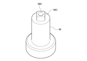
- FIG. 3 is a perspective view of a shear blade rotating shaft.
- FIG. 1 is a longitudinal cross-sectional view of a stirring device 10 according to an embodiment of the present invention.
- the stirring device 10 is installed in the vertical direction, which is the vertical direction or vertical direction in FIG. Use horizontal direction interchangeably.
- the present invention is also applicable to a stirring device 10 that is not installed vertically, and in such a case, the vertical direction, the vertical direction, and the vertical direction are different, and the horizontal direction, the horizontal direction, and the horizontal direction are different.
- the fluidizing blade rotating shaft 34 of the fluidizing blade 14 the shearing blade rotating shaft 46 of the shearing blade 16, the gate blade rotating shaft 52 of the gate blade 18, etc.
- each blade has a rotating axis
- the vertical direction, longitudinal direction, and vertical direction are also referred to as axial directions.
- the left-right direction, the lateral direction, and the horizontal direction determine the diameters of the stirring tank 12, the fluidizing blades 14, the shearing blades 16, the gate blades 18, etc., so the left-right direction, the lateral direction, and the horizontal direction are also referred to as radial directions.
- the stirring device 10 includes a stirring tank 12 that accommodates a fluid to be stirred, a fluidizing blade 14 as a rotary blade that can rotate around rotational shafts 34, 46, and 52 in the axial direction within the stirring tank 12, a shearing blade 16, A gate wing 18 is provided.
- the stirring tank 12 includes a cylindrical or tubular straight body part 20 that is provided above and extends in the axial direction, a bottom part 22 that is continuous with the straight body part 20 and provided below, and a bottom part 22 that is continuous with the straight body part 20. It has a top portion 24 provided above.
- the bottom portion 22 of the stirring tank 12 in this embodiment has a planar shape with the axial direction as the normal direction. As will be described later, forming the bottom portion 22 in a planar shape has the advantage that the distance in the axial direction from the shearing blade 16 can be reduced. It is applicable to the stirring tank 12 having the bottom 22 of any shape.
- the planar bottom portion 22 of the stirring tank 12 can be attached to a flange portion 21 formed to project in the radial direction at the bottom or lowest part of the cylindrical side wall 12a or the straight body portion 20 of the stirring tank 12. . That is, when assembling the stirring tank 12, the flat bottom portion 22 may be brought into contact with the flange portion 21 of the straight body portion 20 from below and fixed using a fixing device such as a screw. At this time, the shearing blades 16, shearing blade rotation shaft 46, shearing blade drive unit 47, etc., which will be described later, may be attached to the bottom part 22 in advance, or after the bottom part 22 is attached to the flange part 21, the shearing blades 16, the shearing blade drive part 47, etc.
- a blade rotation shaft 46, a shear blade drive unit 47, etc. may be attached to the bottom portion 22.
- the top part 24 of the stirring tank 12 in this embodiment has a planar shape with the axial direction as the normal direction.
- the planar top portion 24 of the stirring tank 12 can be attached to a flange portion 23 formed to project in the radial direction at the top or top of the cylindrical side wall 12a or the straight body portion 20 of the stirring tank 12. . That is, when assembling the stirring tank 12, the flat top portion 24 may be brought into contact with the flange portion 23 of the straight body portion 20 from above and fixed using a fixing device such as a screw.
- a fluidizing blade 14, a fluidizing blade rotating shaft 34 which will be described later, a fluidizing blade driving section (not shown) provided above in FIG.
- the gate blade drive unit, etc. may be attached to the top portion 24 in advance, or after the top portion 24 is attached to the flange portion 23, the fluidization blade 14, fluidization vane rotation shaft 34, fluidization vane drive unit, gate blade 18, and gate blade A rotating shaft 52, a gate blade drive unit, etc. may be attached to the top portion 24.
- the inner circumferential wall or side wall 12a of the straight body portion 20 of the stirring tank 12 has a circular cross section when viewed from above, and its diameter D is hereinafter also referred to as tank diameter D.
- tank diameter D the cross section of the straight body portion 20 and/or the stirring tank 12 when viewed from above may have any non-circular shape.
- the tank diameter D of the stirring tank 12 may be the diameter of the inscribed circle of the cross-sectional shape, the diameter of the circumscribed circle of the cross-sectional shape, or the average value or intermediate value thereof.
- At least a portion of the upper part of the straight body part 20 is opened so that a fluid to be stirred can be introduced thereinto, and can be closed with a lid or the like while the fluid is being stirred by the stirring device 10.
- the fluid to be stirred may be supplied into the stirring tank 12 from a fluid supply port such as a supply nozzle provided on the side surface of the straight body portion 20.
- the fluidizing blades 14, shearing blades 16, and gate blades 18 are each individually driven to rotate around a rotation axis in the vertical direction (vertical direction in FIG. 1) by a drive unit such as a motor or a speed reducer provided outside the stirring tank 12. be done.
- a drive unit such as a motor or a speed reducer provided outside the stirring tank 12.
- the flow blade rotation axis 34 of the flow blade 14, the shear blade rotation axis 46 of the shear blade 16, and the gate blade rotation axis 52 of the gate blade 18 do not have to be provided on the same straight line as in the example of FIG. Often, the respective directions may be different from each other.
- the rotation direction and rotation speed of the fluidizing blade 14, shearing blade 16, and gate blade 18 can be set or controlled independently of each other, and can be set or controlled independently of each other, depending on the capacity and shape of the stirring tank 12, the properties of the fluid in the stirring tank 12, and what should occur in the stirring tank 12. It is optimally set or controlled by taking into consideration various conditions such as the speed and phase of chemical reactions.
- the rotation speed of the shear blade 16, which is responsible for shearing and atomizing the fluid itself, fine particles in the fluid, aggregates thereof, etc., is higher than the rotation speed of the flow blade 14 and/or the gate blade 18, which is responsible for the flow of the fluid. big.
- the capacity of the stirring tank 12 is about 10 [l]
- the typical rotation speed of the fluidizing blade 14 is 20-30 [rpm]
- the rotation speed of the shearing blade 16 is about 1,200 [rpm].
- the capacity of the stirring tank 12 is about 1,000 [l]
- the typical rotational speed of the fluidizing blades 14 is 20-30[rpm]
- the rotational speed of the shearing blades 16 is 600-900[rpm]. ] is preferable.
- the rotational speed of the shearing blades 16 is preferably at least 20 times the rotational speed of the flow blades 14. Note that in order to obtain the same shearing performance as the large-diameter shearing blade 16 in this embodiment with the small-diameter disper blade in Patent Document 1, a rotation speed of about 3,600 [rpm] is required. According to the shearing blade 16 that can be made larger in diameter as described later, the rotational speed required to obtain the desired shearing performance or atomization performance is low, so by employing a low-power shearing blade drive unit 47, stirring can be improved. The device 10 can be made smaller or lower in cost.
- the fluidizing vane rotation shaft 34 of the fluidizing vane 14 is formed into a cylindrical or tubular shape, and the gate vane rotating shaft 52 of the gate vane 18 passes through the inside thereof.
- the fluidizing blade rotation shaft 34 of the fluidizing blade 14 and the gate blade rotating shaft 52 of the gate blade 18 extend from the top 24 of the stirring tank 12 into the stirring tank 12 .
- the fluidized vane rotation shaft 34 is rotationally driven by a fluidized vane drive unit (not shown) provided above in FIG. It is rotationally driven inside the rotating shaft 34.
- the flow blade drive unit and the gate blade drive unit be configured by different motors, it is preferable that they be configured integrally as one drive unit including the plurality of motors.
- the shear blade rotating shaft 46 of the shear blade 16 as a stirring blade extends into the stirring tank 12 from the bottom 22 of the stirring tank 12.
- the shearing blade rotation shaft 46 is rotationally driven by a shearing blade driving section 47 provided below in FIG.
- the drive unit below the stirring tank 12 that constitutes the shear blade drive section 47 is different from the drive unit above the stirring tank 12 that constitutes the aforementioned fluidization blade drive section and/or gate blade drive section.
- the fluidizing vane 14 is rotated around the fluidizing vane rotating shaft 34 by the fluidizing vane driving section to cause the fluid to flow within the stirring tank 12 .
- the fluidized vanes 14 in the illustrated example are a pair of ribbon vanes that are spirally formed around a vertical fluidized vane rotation axis 34 .
- the shape of the fluidizing blade 14 is not limited to a spiral shape or a ribbon shape, but in order to secure a sufficient space for installing a shearing blade 16, which will be described later, in an area facing the bottom 22 of the stirring tank 12, It is preferable to have a shape that has few portions that are close to each other. For this reason, the illustrated ribbon wing is preferable to the anchor wing having a shape that follows the bottom portion 22.
- the ribbon blades in the illustrated example face the bottom portion 22 at a location close to the side wall 12a of the stirring tank 12, but as will be described later, the shear blades 16 are located in the radially central region of the stirring tank 12 (shear blade rotation axis 46).
- the fluidizing blades 14 (ribbon blades) and shearing blades 16 (stirring blades) do not interfere with each other.
- the bottom 22 of the stirring tank 12 is often provided with a discharge port through which the fluid to be stirred settles and the fluid after stirring is discharged. Balance is required.
- the quality of the agitated fluid in the bottom 22 can be improved by configuring the flow blade 14 to rotate in the outer peripheral area of the bottom 22 and the shear blade 16 to rotate in the central area of the bottom 22. Furthermore, since the flow blades 14 are present only in the outer peripheral region of the bottom portion 22, the diameter of the shear blades 16 in the central region of the bottom portion 22 can be increased.
- the fluid vane 14 includes a plurality of band-shaped fluid vane bodies 26 (two in the example of FIG. 1) having a predetermined width, and a plurality of fluid vane bodies 26 that engage with the inner circumferential portion of each fluid vane body 26 at the upper and lower ends of each fluid vane body 26. (Two in the example of FIG. 1) support rods 28 are provided.
- the plurality of flow blade bodies 26 and the plurality of support rods 28 are integrated by welding or the like in a combined state as shown in the figure.
- Each support rod 28 is a rod-shaped member extending in the axial direction, and is supported by being engaged with the upper and lower ends of each fluid vane main body 26.
- each support rod 28 is engaged with a plurality of different fluid vane bodies 26, and each fluid vane body 26 is engaged with a plurality of different support bars 28.
- each support rod 28 may be provided on the same circumference as the two support rods 28 shown in FIG. 1 in a top view, and at intermediate positions therebetween. These two support rods 28 provided at the front and back of the plane of the drawing of FIG. maintains the desired spiral shape.
- the upper end of each support rod 28 is connected to a vertical fluidizing vane rotating shaft 34 .
- the fluid vane drive unit (not shown) rotationally drives the fluid vane rotating shaft 34
- the fluid vane 14 which is made up of the mutually connected support rod 28 and fluid vane main body 26, rotates integrally, and the above-mentioned downward induced flow is caused. It is formed.
- Each fluidized vane main body 26 is formed to rotate 180 degrees around the fluidized vane rotation axis 34 when viewed from above. Therefore, as described above, the upper end of each fluid vane main body 26 engages with one of the support rods 28, and the lower end of each fluid vane main body 26 engages with one of the support rods 28 when viewed from above.
- the other support rod 28 is engaged with the other support rod 28 in a point-symmetrical position (rotated position of 180 degrees) about the axis 34 .
- a gate blade 18 as an auxiliary blade or an internal blade having a smaller diameter than the flow blade 14 is installed on the radially central side or inside of the flow blade 14 .
- the gate blade 18 is rotationally driven around the gate blade rotating shaft 52 by a gate blade drive unit, and causes the fluid to flow in the stirring tank 12 inside the fluidizing blade 14 in a manner different from that of the fluidizing blade 14 .
- a shearing blade 16 described below is installed below the gate blade 18, the axial distance between the bottom 22 of the stirring tank 12 and the gate blade 18 (lower member 48D described later) is determined by the installation of the shearing blade 16. larger than the space or installation height. In other words, the space below the gate blades 18 can be utilized to the fullest by the shear blades 16.
- the gate blade 18 includes a rectangular frame-shaped gate blade main body 48 that is symmetrical about a vertical rotation axis (gate blade rotation axis 52), and a gate blade main body 48 that is connected to the upper part of the gate blade main body 48 and rotated by a gate blade drive unit (not shown).
- a driven axial gate blade rotation shaft 52 is provided.
- the gate wing main body 48 includes a radially upper member 48U, an axially left member 48L, an axially right member 48R, and a radially lower member 48D, which are each formed into a rod shape or columnar shape and are integrally formed in a rectangular shape. It has a standardized frame structure.
- the rotational direction and rotational speed of the gate blade 18 are arbitrary, typically the gate blade 18 rotates in the opposite direction to the flow blade 14, or rotates in the same direction as the flow blade 14 at a different speed or rotational speed. .
- the moving speed of the object to be stirred due to the rotation of the fluidizing blade 14 and the moving speed of the object to be stirred due to the rotation of the gate blade 18 can be changed. It makes a difference. Therefore, "co-rotation" in which the object to be stirred in the stirring tank 12 rotates together with the fluidizing blade 14 can be suppressed, and the object to be stirred in the stirring tank 12 can be made to flow efficiently. Furthermore, by appropriately setting the rotational direction and/or rotational speed of the gate blades 18, it is possible to generate a flow that causes the object to be stirred, which has been sheared by the shear blades 16 below the gate blades 18, to flow upward.
- the guided flow directed upward in the center of the stirring tank 12 generated by the gate blade 18 is changed by the fluidizing blade 14 into a guided flow directed downward along the side wall 12a of the stirring tank 12, and then flows back into the shear blade 16. Head towards. Since a circulating flow is thus formed between the fluidizing blades 14, the shearing blades 16, and the gate blades 18, the object to be stirred can be efficiently stirred.
- the shearing blade 16 as a stirring blade provided between the bottom 22 of the stirring tank 12 and the fluidizing blade 14 rotates around the shearing blade rotating shaft 46 by a shearing blade drive unit 47 to shear or shear the fluid in the stirring tank 12.
- the shearing blade 16 includes a pair of blade parts 17A and 17B (hereinafter also collectively referred to as the blade part 17) extending in the radial direction from the shearing blade rotating shaft 46 toward the side wall 12a of the stirring tank 12.
- the blade portion 17 In the radial direction (horizontal direction), the blade portion 17 is arranged in a central region on the center side or inside the lower end portion of the fluidizing blade 14 that rotates in the outer circumferential region of the stirring tank 12 or the bottom portion 22. Therefore, at least a portion (lower end portion) of the fluidizing blade 14 does not interfere with the blade portion 17 between the tip portion (the left end portion and the right end portion in FIG. 1) of the blade portion 17 and the side wall 12a of the stirring tank 12. It rotates without any problem. Further, the blade portion 17 is arranged between the upper gate blade 18 and the bottom portion 22 of the lower stirring tank 12 in the axial direction (vertical direction). That is, the blade portion 17 is arranged in the central region facing the bottom portion 22 of the stirring tank 12 .
- the shearing blade 16 including the blade part 17 extending in the radial direction approximately parallel to the bottom part 22 is connected to the upper gate blade 18 in the left-right direction. It can be efficiently or compactly arranged in a substantially rectangular parallelepiped region surrounded by the fluidizing blades 14 (lower end portion) and the bottom portion 22 of the stirring tank 12 below.
- FIG. 2 is a schematic side perspective view of the shear blade 16, and FIG. 3 is a top or bottom view of the shear blade 16.
- the shear blade 16 includes a cylindrical boss 161 whose height is in the axial direction (vertical direction in FIG. 2), and a pair of wing portions extending from the boss 161 in the radial direction (horizontal direction in FIGS. 2 and 3). 17A and 17B (wing parts 17).
- An axial attachment hole 46A into which the shear blade rotating shaft 46 is inserted and attached is provided in the radial center of the boss 161. As shown in FIG. 3, the attachment hole 46A is provided at the center of the recess 46B having a substantially rectangular or square cross section.
- a protrusion 46C (FIG. 4) that engages or fits therewith is provided at the upper end of the substantially cylindrical shear blade rotation shaft 46.
- the cross-sectional shape of the convex portion 46C is approximately rectangular or square, and is congruent with or slightly smaller in cross-sectional shape than the recessed portion 46B.
- a mounting hole 46D that communicates with the mounting hole 46A of the boss 161 is provided at the center of the convex portion 46C.
- the wing portion 17 is fixed to the boss 161 by, for example, welding. Note that the wing portion 17 may be directly fixed to the shear blade rotating shaft 46 by welding or the like, without using the boss 161.
- the normal direction of the stirring surface (surface) of each of the flat blades 17A, 17B is the axial direction of the shearing blade rotating shaft 46 (the vertical direction in FIG. 2) and the rotational direction of each of the blades 17A, 17B (the shearing blade It is inclined with respect to either direction (rotation direction around the rotation axis 46).
- a stirring blade or shearing blade including such a blade portion 17 is sometimes called an inclined paddle blade.
- the angle between the normal direction of the stirring surface of each blade part 17A, 17B and the axial direction of the shear blade rotating shaft 46 is 15 degrees or less (the angle formed with the rotation direction of each blade part 17A, 17B is 75 degrees or more) It is preferable that As a result, the stirring surfaces of the blades 17A, 17B are approximately parallel to the bottom 22 of the stirring tank 12 (forming an angle of 15 degrees or less), so the resistance that the rotating stirring surfaces receive from the fluid is reduced. Therefore, even if the diameter of the blade portion 17 is increased, it can be driven with relatively low power, and it is possible to prevent the shear blade drive portion 47 from increasing in size and cost. Furthermore, by inclining the wing section 17 as described above, the wing section 17 is less likely to idle even when using a fluid with high thixotropy or a fluid with low stringiness, so shearing efficiency or atomization efficiency is improved. .
- the non-disc-shaped shearing blade 16 or blade part 17 has a relatively small load power, so the blade diameter can be increased, and since it is light in weight, it is easy to balance the rotation. Therefore, the blade diameter in the extending direction of the blade part 17 (the radial distance between the left end of the blade part 17A and the right end of the blade part 17B in FIGS. 2 and 3) is 35% of the tank diameter D of the stirring tank 12. and 85%, preferably between 45% and 75%, more preferably between 50% and 70% of the tank diameter D of the stirring tank 12. Therefore, the shearing area can be made larger than that of conventional disk-shaped stirring blades, and shearing efficiency or atomization efficiency is improved.
- the shear blades 16 or the entire stirring device 10 of this embodiment are suitable for shearing and atomizing fluids with relatively high viscosity (at least fluids with a viscosity of 1,000 cP or more, for example, 10,000 cP or more).
- a high viscosity fluid include any fluid (oil, varnish, rubber, polymer solution, molten resin, etc.) containing fine particles such as carbon black and silica. Fine particles such as carbon black form aggregates in the fluid, but are efficiently made fine and/or dispersed by the shear blades 16 of this embodiment.
- the width w (Fig. 3) of the tip of the blade section 17 in the rotational direction is set to 5% or less of the tank diameter D of the stirring tank 12. It is preferable to do so.
- the blades 17 and the stirring tank 12 are The distance h (FIG. 1) of the bottom portion 22 is preferably 15% or less of the tank diameter D of the stirring tank 12.
- the shape of the stirring blade of the present invention is not limited to the shape of the shearing blade 16 illustrated in the embodiment.
- the stirring blade provided between the bottom of the stirring tank and the fluidizing blade has one or more blade portions extending from its rotation axis toward the side wall of the stirring tank. Any non-disk shape may be used.
- each device and each method described in the embodiments can be realized by hardware resources or software resources, or by cooperation of hardware resources and software resources.
- hardware resources for example, a processor, ROM, RAM, and various integrated circuits can be used.
- software resources for example, programs such as operating systems and applications can be used.
- the present invention relates to a stirring device and the like.
Abstract
This stirring device 10 comprises: a stirring tank 12 that accommodates a fluid; a fluidizing blade 14 that causes the fluid to flow within the stirring tank 12 by rotating; and a shearing blade 16 that is provided between a bottom part 22 of the stirring tank 12 and the fluidizing blade 14, the shearing blade 16 stirring the fluid by rotating, and the shearing blade 16 being provided with a blade part 17 extending from a shearing blade rotating shaft 46 toward a side wall 12a of the stirring tank 12. At least a part (lower end part) of the fluidizing blade 14 rotates between a distal-end section of the blade part 17 and the side wall 12a of the stirring tank 12. The direction normal to the stirring surface of the blade part 17 is inclined with respect to both the axial direction of the shear blade rotating shaft 46 and the rotation direction of the blade part 17. The bottom part 22 of the stirring tank is a flat surface.
Description
本発明は撹拌装置等に関する。
The present invention relates to a stirring device and the like.
撹拌槽内の流体を撹拌する撹拌装置として、特許文献1には流動翼と円板状の剪断翼(ディスパー翼)を備えるものが開示されている。流動翼の回転によって形成される流れに接する中央位置に設けられるディスパー翼が流体を効果的に剪断する。
As a stirring device that stirs the fluid in a stirring tank, Patent Document 1 discloses one that includes a fluidizing blade and a disc-shaped shearing blade (disper blade). A disper vane provided at a central position in contact with the flow formed by the rotation of the fluid vane effectively shears the fluid.
特許文献1のディスパー翼はディスク状であるため、翼径を大きくすると負荷動力が大きく、また、回転バランスが取りづらくなる。このため、特許文献1のディスパー翼の翼径は小さくしなければならない。具体的には、特許文献1における段落0031にあるように、ディスパー翼の翼径は撹拌槽の槽径の10%と30%の間とされる。この場合、例えば撹拌装置の撹拌対象の流体の粘度が高くなると、動力の問題からディスパー翼の翼径をより小さくする必要があり、流体が小径のディスパー翼に到達しにくくなる恐れがある。
Since the disper blade of Patent Document 1 is disk-shaped, increasing the blade diameter increases the load power and makes it difficult to maintain rotational balance. For this reason, the blade diameter of the disper blade of Patent Document 1 must be made small. Specifically, as described in paragraph 0031 of Patent Document 1, the diameter of the disper blade is between 10% and 30% of the diameter of the stirring tank. In this case, for example, if the viscosity of the fluid to be stirred by the stirring device increases, the blade diameter of the disper blade must be made smaller due to power issues, and there is a risk that the fluid will have difficulty reaching the small diameter disper blade.
本発明はこうした状況に鑑みてなされたものであり、粘度の高い流体やチキソトロピー性の高い流体であっても効果的に撹拌できる撹拌装置等を提供することを目的とする。
The present invention has been made in view of these circumstances, and it is an object of the present invention to provide a stirring device etc. that can effectively stir even highly viscous fluids and highly thixotropic fluids.
上記課題を解決するために、本発明のある態様の撹拌装置は、流体を収容する撹拌槽と、回転によって流体を撹拌槽内で流動させる流動翼と、撹拌槽の底部と流動翼の間に設けられ、回転によって流体を撹拌する撹拌翼であって、その回転軸から撹拌槽の側壁に向かって延在する翼部を備える撹拌翼と、を備える。
In order to solve the above problems, a stirring device according to an embodiment of the present invention includes a stirring tank that accommodates a fluid, a fluidizing blade that causes the fluid to flow in the stirring tank by rotation, and a space between the bottom of the stirring tank and the fluidizing blade. The stirring blade includes a stirring blade that is provided and that stirs a fluid by rotation, and includes a blade portion that extends from the rotation axis toward the side wall of the stirring tank.
この態様では、回転軸から撹拌槽の側壁に向かって延在する翼部を備える非ディスク状の撹拌翼を利用することで、特許文献1のディスク状のディスパー翼のように翼径を小さくする必要がない。このように従来に比べて大径化できる撹拌翼には、流動翼が発生させる流れが到達しやすくなるため、粘度の高い流体であっても効果的に撹拌される。
In this aspect, by using a non-disk-shaped stirring blade having a blade extending from the rotating shaft toward the side wall of the stirring tank, the blade diameter is reduced like the disk-shaped disper blade of Patent Document 1. There's no need. In this way, the flow generated by the fluidizing blades can more easily reach the stirring blades, which can have a larger diameter than conventional ones, so that even highly viscous fluids can be effectively stirred.
本発明の別の態様は、撹拌方法である。この方法は、流動翼を回転させて撹拌槽内で流体を流動させることと、撹拌槽の底部と流動翼の間に設けられ、その回転軸から撹拌槽の側壁に向かって延在する翼部を備える撹拌翼を、流動翼より高速に回転させて流体を撹拌することと、を備える。
Another aspect of the present invention is a stirring method. This method consists of rotating a fluidizing blade to cause the fluid to flow in a stirring tank, and a blade section provided between the bottom of the stirring tank and the fluidizing blade and extending from the rotation axis toward the side wall of the stirring tank. and stirring the fluid by rotating an agitating blade equipped with the fluidizing blade at a higher speed than the fluidizing blade.
なお、以上の構成要素の任意の組合せや、これらの表現を方法、装置、システム、記録媒体、コンピュータプログラム等に変換したものも、本発明に包含される。
It should be noted that the present invention also encompasses any combination of the above components and the conversion of these expressions into methods, devices, systems, recording media, computer programs, etc.
本発明によれば、粘度の高い流体やチキソトロピー性の高い流体であっても効果的に撹拌できる。
According to the present invention, even highly viscous fluids or highly thixotropic fluids can be effectively stirred.
以下では、図面を参照しながら、本発明を実施するための形態(以下では実施形態ともいう)について詳細に説明する。説明および/または図面においては、同一または同等の構成要素、部材、処理等に同一の符号を付して重複する説明を省略する。図示される各部の縮尺や形状は、説明の簡易化のために便宜的に設定されており、特に言及がない限り限定的に解釈されるものではない。実施形態は例示であり、本発明の範囲を何ら限定するものではない。実施形態に記載される全ての特徴やそれらの組合せは、必ずしも本発明の本質的なものであるとは限らない。
Hereinafter, modes for carrying out the present invention (hereinafter also referred to as embodiments) will be described in detail with reference to the drawings. In the description and/or drawings, the same or equivalent components, members, processes, etc. are denoted by the same reference numerals, and redundant description will be omitted. The scales and shapes of the parts shown in the drawings are set for convenience to simplify the explanation, and should not be interpreted in a limited manner unless otherwise stated. The embodiments are illustrative and do not limit the scope of the present invention. Not all features or combinations thereof described in the embodiments are necessarily essential to the present invention.
図1は、本発明の実施形態に係る撹拌装置10の縦断面図である。本実施形態では、撹拌装置10が図1の上下方向または縦方向である鉛直方向に設置されるものとし、上下方向、縦方向、鉛直方向を同義的に使用すると共に、左右方向、横方向、水平方向を同義的に使用する。なお、本発明は鉛直方向に設置されない撹拌装置10にも適用可能であり、そのような場合には上下方向、縦方向と鉛直方向が異なり、左右方向、横方向と水平方向が異なる。また、後述するように、上下方向、縦方向、鉛直方向には、流動翼14の流動翼回転軸34、剪断翼16の剪断翼回転軸46、ゲート翼18のゲート翼回転軸52等の各翼の各回転軸が設けられるため、上下方向、縦方向、鉛直方向を軸方向ともいう。更に、左右方向、横方向、水平方向は撹拌槽12、流動翼14、剪断翼16、ゲート翼18等の径を定めるため、左右方向、横方向、水平方向を径方向ともいう。
FIG. 1 is a longitudinal cross-sectional view of a stirring device 10 according to an embodiment of the present invention. In this embodiment, the stirring device 10 is installed in the vertical direction, which is the vertical direction or vertical direction in FIG. Use horizontal direction interchangeably. Note that the present invention is also applicable to a stirring device 10 that is not installed vertically, and in such a case, the vertical direction, the vertical direction, and the vertical direction are different, and the horizontal direction, the horizontal direction, and the horizontal direction are different. In addition, as will be described later, in the vertical, longitudinal, and vertical directions, the fluidizing blade rotating shaft 34 of the fluidizing blade 14, the shearing blade rotating shaft 46 of the shearing blade 16, the gate blade rotating shaft 52 of the gate blade 18, etc. Since each blade has a rotating axis, the vertical direction, longitudinal direction, and vertical direction are also referred to as axial directions. Furthermore, the left-right direction, the lateral direction, and the horizontal direction determine the diameters of the stirring tank 12, the fluidizing blades 14, the shearing blades 16, the gate blades 18, etc., so the left-right direction, the lateral direction, and the horizontal direction are also referred to as radial directions.
撹拌装置10は、撹拌対象の流体を収容する撹拌槽12と、撹拌槽12内で軸方向の回転軸34、46、52の周りに回転可能な回転翼としての流動翼14、剪断翼16、ゲート翼18を備える。撹拌槽12は、上方に設けられて軸方向に延在する筒状または管状の直胴部20と、直胴部20と連続して下方に設けられる底部22と、直胴部20と連続して上方に設けられる頂部24を備える。本実施形態における撹拌槽12の底部22は、軸方向を法線方向とする平面状である。後述するように、底部22を平面状に形成することで剪断翼16との軸方向の距離を小さくできるという利点があるが、本発明は曲面状や特許文献1のような逆円錐状等の任意の形状の底部22を有する撹拌槽12に適用可能である。
The stirring device 10 includes a stirring tank 12 that accommodates a fluid to be stirred, a fluidizing blade 14 as a rotary blade that can rotate around rotational shafts 34, 46, and 52 in the axial direction within the stirring tank 12, a shearing blade 16, A gate wing 18 is provided. The stirring tank 12 includes a cylindrical or tubular straight body part 20 that is provided above and extends in the axial direction, a bottom part 22 that is continuous with the straight body part 20 and provided below, and a bottom part 22 that is continuous with the straight body part 20. It has a top portion 24 provided above. The bottom portion 22 of the stirring tank 12 in this embodiment has a planar shape with the axial direction as the normal direction. As will be described later, forming the bottom portion 22 in a planar shape has the advantage that the distance in the axial direction from the shearing blade 16 can be reduced. It is applicable to the stirring tank 12 having the bottom 22 of any shape.
撹拌槽12の平面状の底部22は、当該撹拌槽12の筒状の側壁12aまたは直胴部20の底部または最下部において径方向に張り出すように形成されるフランジ部21に取付可能である。すなわち、撹拌槽12を組み立てる際には、平板状の底部22を下方から直胴部20のフランジ部21に接触させ、ねじ等の固定具によって固定すればよい。この際、後述する剪断翼16、剪断翼回転軸46、剪断翼駆動部47等が予め底部22に取り付けられていてもよいし、底部22がフランジ部21に取り付けられた後に剪断翼16、剪断翼回転軸46、剪断翼駆動部47等が底部22に取り付けられてもよい。このように、撹拌槽12の底部22を平面状に形成することで、撹拌槽12および撹拌装置10の組立性を向上できる。
The planar bottom portion 22 of the stirring tank 12 can be attached to a flange portion 21 formed to project in the radial direction at the bottom or lowest part of the cylindrical side wall 12a or the straight body portion 20 of the stirring tank 12. . That is, when assembling the stirring tank 12, the flat bottom portion 22 may be brought into contact with the flange portion 21 of the straight body portion 20 from below and fixed using a fixing device such as a screw. At this time, the shearing blades 16, shearing blade rotation shaft 46, shearing blade drive unit 47, etc., which will be described later, may be attached to the bottom part 22 in advance, or after the bottom part 22 is attached to the flange part 21, the shearing blades 16, the shearing blade drive part 47, etc. A blade rotation shaft 46, a shear blade drive unit 47, etc. may be attached to the bottom portion 22. By forming the bottom portion 22 of the stirring tank 12 in a planar shape in this way, the ease of assembling the stirring tank 12 and the stirring device 10 can be improved.
底部22と同様に、本実施形態における撹拌槽12の頂部24は、軸方向を法線方向とする平面状である。撹拌槽12の平面状の頂部24は、当該撹拌槽12の筒状の側壁12aまたは直胴部20の頂部または最上部において径方向に張り出すように形成されるフランジ部23に取付可能である。すなわち、撹拌槽12を組み立てる際には、平板状の頂部24を上方から直胴部20のフランジ部23に接触させ、ねじ等の固定具によって固定すればよい。この際、後述する流動翼14、流動翼回転軸34、図1の上方に設けられる不図示の流動翼駆動部、ゲート翼18、ゲート翼回転軸52、図1の上方に設けられる不図示のゲート翼駆動部等が予め頂部24に取り付けられていてもよいし、頂部24がフランジ部23に取り付けられた後に流動翼14、流動翼回転軸34、流動翼駆動部、ゲート翼18、ゲート翼回転軸52、ゲート翼駆動部等が頂部24に取り付けられてもよい。
Similar to the bottom part 22, the top part 24 of the stirring tank 12 in this embodiment has a planar shape with the axial direction as the normal direction. The planar top portion 24 of the stirring tank 12 can be attached to a flange portion 23 formed to project in the radial direction at the top or top of the cylindrical side wall 12a or the straight body portion 20 of the stirring tank 12. . That is, when assembling the stirring tank 12, the flat top portion 24 may be brought into contact with the flange portion 23 of the straight body portion 20 from above and fixed using a fixing device such as a screw. At this time, a fluidizing blade 14, a fluidizing blade rotating shaft 34, which will be described later, a fluidizing blade driving section (not shown) provided above in FIG. 1, a gate blade 18, a gate blade rotating shaft 52, The gate blade drive unit, etc. may be attached to the top portion 24 in advance, or after the top portion 24 is attached to the flange portion 23, the fluidization blade 14, fluidization vane rotation shaft 34, fluidization vane drive unit, gate blade 18, and gate blade A rotating shaft 52, a gate blade drive unit, etc. may be attached to the top portion 24.
撹拌槽12の直胴部20の内周壁または側壁12aは上面視で円状の断面を有し、その直径Dを以下では槽径Dともいう。なお、直胴部20および/または撹拌槽12の上面視の断面は非円状の任意の形状でよい。この場合の撹拌槽12の槽径Dは、断面形状の内接円の直径でもよいし、断面形状の外接円の直径でもよいし、これらの平均値や中間値でもよい。直胴部20の上方の少なくとも一部は撹拌対象の流体を投入できるように開口されており、撹拌装置10による流体の撹拌中には蓋等によって閉塞可能になっている。なお、撹拌対象の流体は、直胴部20の側面に設けられる供給ノズル等の流体供給口から撹拌槽12内に供給されてもよい。
The inner circumferential wall or side wall 12a of the straight body portion 20 of the stirring tank 12 has a circular cross section when viewed from above, and its diameter D is hereinafter also referred to as tank diameter D. Note that the cross section of the straight body portion 20 and/or the stirring tank 12 when viewed from above may have any non-circular shape. In this case, the tank diameter D of the stirring tank 12 may be the diameter of the inscribed circle of the cross-sectional shape, the diameter of the circumscribed circle of the cross-sectional shape, or the average value or intermediate value thereof. At least a portion of the upper part of the straight body part 20 is opened so that a fluid to be stirred can be introduced thereinto, and can be closed with a lid or the like while the fluid is being stirred by the stirring device 10. Note that the fluid to be stirred may be supplied into the stirring tank 12 from a fluid supply port such as a supply nozzle provided on the side surface of the straight body portion 20.
流動翼14、剪断翼16、ゲート翼18は、撹拌槽12外に設けられるモータや減速機等の駆動部によって、それぞれ鉛直方向(図1における上下方向)の回転軸の周りに個別に回転駆動される。なお、流動翼14の流動翼回転軸34、剪断翼16の剪断翼回転軸46、ゲート翼18のゲート翼回転軸52は、図1の例のように互いに同一直線上に設けられなくてもよく、それぞれの方向が互いに異なっていてもよい。流動翼14、剪断翼16、ゲート翼18の回転方向や回転速度は互いに独立に設定または制御でき、撹拌槽12の容量や形状、撹拌槽12内の流体の性質、撹拌槽12内で起こすべき化学反応の速度やフェーズ等の各種の条件を考慮の上で最適に設定または制御される。
The fluidizing blades 14, shearing blades 16, and gate blades 18 are each individually driven to rotate around a rotation axis in the vertical direction (vertical direction in FIG. 1) by a drive unit such as a motor or a speed reducer provided outside the stirring tank 12. be done. Note that the flow blade rotation axis 34 of the flow blade 14, the shear blade rotation axis 46 of the shear blade 16, and the gate blade rotation axis 52 of the gate blade 18 do not have to be provided on the same straight line as in the example of FIG. Often, the respective directions may be different from each other. The rotation direction and rotation speed of the fluidizing blade 14, shearing blade 16, and gate blade 18 can be set or controlled independently of each other, and can be set or controlled independently of each other, depending on the capacity and shape of the stirring tank 12, the properties of the fluid in the stirring tank 12, and what should occur in the stirring tank 12. It is optimally set or controlled by taking into consideration various conditions such as the speed and phase of chemical reactions.
典型的には、流体自体、流体中の微粒子、その凝集体等の剪断や微細化を担う剪断翼16の回転速度は、流体の流動を担う流動翼14および/またはゲート翼18の回転速度より大きい。例えば、撹拌槽12の容量が10[l]程度の場合の流動翼14の典型的な回転速度が20-30[rpm]であるのに対し、剪断翼16の回転速度は1,200[rpm]程度とするのが好ましい。また、撹拌槽12の容量が1,000[l]程度の場合の流動翼14の典型的な回転速度が20-30[rpm]であるのに対し、剪断翼16の回転速度は600-900[rpm]とするのが好ましい。このように、剪断翼16の回転速度は、流動翼14の回転速度の少なくとも20倍とするのが好ましい。なお、本実施形態における大径の剪断翼16と同等の剪断性能を特許文献1における小径のディスパー翼で得るためには、3,600[rpm]程度の回転速度が必要になる。後述するように大径化が可能な剪断翼16によれば、所望の剪断性能または微細化性能を得るための回転速度が小さくなるため、低動力の剪断翼駆動部47を採用することで撹拌装置10を小型化または低コスト化できる。
Typically, the rotation speed of the shear blade 16, which is responsible for shearing and atomizing the fluid itself, fine particles in the fluid, aggregates thereof, etc., is higher than the rotation speed of the flow blade 14 and/or the gate blade 18, which is responsible for the flow of the fluid. big. For example, when the capacity of the stirring tank 12 is about 10 [l], the typical rotation speed of the fluidizing blade 14 is 20-30 [rpm], whereas the rotation speed of the shearing blade 16 is about 1,200 [rpm]. It is preferable that Furthermore, when the capacity of the stirring tank 12 is about 1,000 [l], the typical rotational speed of the fluidizing blades 14 is 20-30[rpm], whereas the rotational speed of the shearing blades 16 is 600-900[rpm]. ] is preferable. Thus, the rotational speed of the shearing blades 16 is preferably at least 20 times the rotational speed of the flow blades 14. Note that in order to obtain the same shearing performance as the large-diameter shearing blade 16 in this embodiment with the small-diameter disper blade in Patent Document 1, a rotation speed of about 3,600 [rpm] is required. According to the shearing blade 16 that can be made larger in diameter as described later, the rotational speed required to obtain the desired shearing performance or atomization performance is low, so by employing a low-power shearing blade drive unit 47, stirring can be improved. The device 10 can be made smaller or lower in cost.
流動翼14の流動翼回転軸34は筒状または管状に形成されており、その内部をゲート翼18のゲート翼回転軸52が挿通している。流動翼14の流動翼回転軸34およびゲート翼18のゲート翼回転軸52は、撹拌槽12の頂部24から当該撹拌槽12内に延在する。流動翼回転軸34は、図1の上方に設けられる不図示の流動翼駆動部によって回転駆動され、ゲート翼回転軸52は、図1の上方に設けられる不図示のゲート翼駆動部によって流動翼回転軸34の内部で回転駆動される。流動翼駆動部とゲート翼駆動部は異なるモータによって構成されるのが好ましいが、当該複数のモータを含む一つの駆動ユニットとして一体的に構成されるのが好ましい。
The fluidizing vane rotation shaft 34 of the fluidizing vane 14 is formed into a cylindrical or tubular shape, and the gate vane rotating shaft 52 of the gate vane 18 passes through the inside thereof. The fluidizing blade rotation shaft 34 of the fluidizing blade 14 and the gate blade rotating shaft 52 of the gate blade 18 extend from the top 24 of the stirring tank 12 into the stirring tank 12 . The fluidized vane rotation shaft 34 is rotationally driven by a fluidized vane drive unit (not shown) provided above in FIG. It is rotationally driven inside the rotating shaft 34. Although it is preferable that the flow blade drive unit and the gate blade drive unit be configured by different motors, it is preferable that they be configured integrally as one drive unit including the plurality of motors.
撹拌翼としての剪断翼16の剪断翼回転軸46は、撹拌槽12の底部22から当該撹拌槽12内に延在する。剪断翼回転軸46は、図1の下方に設けられる剪断翼駆動部47によって回転駆動される。剪断翼駆動部47を構成する撹拌槽12の下方の駆動ユニットは、前述の流動翼駆動部および/またはゲート翼駆動部を構成する撹拌槽12の上方の駆動ユニットと異なる。
The shear blade rotating shaft 46 of the shear blade 16 as a stirring blade extends into the stirring tank 12 from the bottom 22 of the stirring tank 12. The shearing blade rotation shaft 46 is rotationally driven by a shearing blade driving section 47 provided below in FIG. The drive unit below the stirring tank 12 that constitutes the shear blade drive section 47 is different from the drive unit above the stirring tank 12 that constitutes the aforementioned fluidization blade drive section and/or gate blade drive section.
流動翼14は、流動翼駆動部によって流動翼回転軸34の周りに回転して流体を撹拌槽12内で流動させる。図示の例の流動翼14は、鉛直方向の流動翼回転軸34の周りに螺旋状に形成される一対のリボン翼である。なお、流動翼14の形状は螺旋状またはリボン状に限られるものではないが、撹拌槽12の底部22に対向する領域に後述する剪断翼16を設置するスペースを十分に確保するため、底部22と近接する部分が少ない形状とするのが好ましい。このため、底部22に沿った形状を有するアンカー翼より図示の例のリボン翼の方が好ましい。
The fluidizing vane 14 is rotated around the fluidizing vane rotating shaft 34 by the fluidizing vane driving section to cause the fluid to flow within the stirring tank 12 . The fluidized vanes 14 in the illustrated example are a pair of ribbon vanes that are spirally formed around a vertical fluidized vane rotation axis 34 . Note that the shape of the fluidizing blade 14 is not limited to a spiral shape or a ribbon shape, but in order to secure a sufficient space for installing a shearing blade 16, which will be described later, in an area facing the bottom 22 of the stirring tank 12, It is preferable to have a shape that has few portions that are close to each other. For this reason, the illustrated ribbon wing is preferable to the anchor wing having a shape that follows the bottom portion 22.
なお、図示の例のリボン翼は撹拌槽12の側壁12aに近接する箇所において底部22に対向するが、後述するように剪断翼16は撹拌槽12の径方向の中央領域(剪断翼回転軸46等の回転軸を中心とする領域)に設置されるため、流動翼14(リボン翼)と剪断翼16(撹拌翼)は干渉しない。撹拌槽12の底部22には、撹拌対象の流体が沈降すると共に撹拌後の流体を排出する排出口が設けられることも多く、流動翼14による流動と剪断翼16による剪断(撹拌)の緻密なバランスが求められる。図示の例のように、底部22の外周領域において流動翼14が回転し、底部22の中央領域において剪断翼16が回転する構成とすることで、底部22における撹拌流体の品質を高められる。また、流動翼14は底部22の外周領域のみに存在するため、底部22の中央領域における剪断翼16を大径化できる。
Note that the ribbon blades in the illustrated example face the bottom portion 22 at a location close to the side wall 12a of the stirring tank 12, but as will be described later, the shear blades 16 are located in the radially central region of the stirring tank 12 (shear blade rotation axis 46). The fluidizing blades 14 (ribbon blades) and shearing blades 16 (stirring blades) do not interfere with each other. The bottom 22 of the stirring tank 12 is often provided with a discharge port through which the fluid to be stirred settles and the fluid after stirring is discharged. Balance is required. As in the illustrated example, the quality of the agitated fluid in the bottom 22 can be improved by configuring the flow blade 14 to rotate in the outer peripheral area of the bottom 22 and the shear blade 16 to rotate in the central area of the bottom 22. Furthermore, since the flow blades 14 are present only in the outer peripheral region of the bottom portion 22, the diameter of the shear blades 16 in the central region of the bottom portion 22 can be increased.
流動翼駆動部によって流動翼回転軸34と一体的に流動翼14が回転すると、直胴部20の側壁12aに沿って下方に向かう誘導流が形成される。この誘導流に乗った撹拌槽12内の流体は底部22まで移動し、その外周領域から剪断翼16が存在する中央領域に導かれて効率的に剪断または撹拌される。
When the fluidizing vane 14 is rotated integrally with the fluidizing vane rotation shaft 34 by the fluidizing vane drive unit, a guided flow directed downward along the side wall 12a of the straight body portion 20 is formed. The fluid in the stirring tank 12 riding on this induced flow moves to the bottom 22, and is led from the outer peripheral region to the central region where the shear blades 16 are present, where it is efficiently sheared or stirred.
流動翼14は、所定幅を有する帯状の複数(図1の例では二つ)の流動翼本体26と、各流動翼本体26の上端部および下端部においてそれぞれの内周部と係合する複数(図1の例では二つ)の支持棒28を備える。複数の流動翼本体26および複数の支持棒28は、図示のように組み合わされた状態で溶接等によって一体化されている。各支持棒28は軸方向に延びる棒状部材であり、各流動翼本体26の上端部および下端部が係合されて支持される。
The fluid vane 14 includes a plurality of band-shaped fluid vane bodies 26 (two in the example of FIG. 1) having a predetermined width, and a plurality of fluid vane bodies 26 that engage with the inner circumferential portion of each fluid vane body 26 at the upper and lower ends of each fluid vane body 26. (Two in the example of FIG. 1) support rods 28 are provided. The plurality of flow blade bodies 26 and the plurality of support rods 28 are integrated by welding or the like in a combined state as shown in the figure. Each support rod 28 is a rod-shaped member extending in the axial direction, and is supported by being engaged with the upper and lower ends of each fluid vane main body 26.
支持棒28および流動翼本体26がそれぞれ二つ設けられる図1の例では、第1の支持棒28には、上方で第1の流動翼本体26の上部翼36の上端部が係合され、下方で第2の流動翼本体26の下部翼38の下端部が係合される。同様に、第2の支持棒28には、上方で第2の流動翼本体26の上部翼36の上端部が係合され、下方で第1の流動翼本体26の下部翼38の下端部が係合される。このように、各支持棒28の上方と下方で係合される流動翼本体26は互いに異なる。換言すれば、各支持棒28には複数の異なる流動翼本体26が係合し、各流動翼本体26は複数の異なる支持棒28に係合する。
In the example of FIG. 1 in which two support rods 28 and two flow blade bodies 26 are provided, the upper end portion of the upper blade 36 of the first flow blade body 26 is engaged with the first support rod 28 above, The lower end of the lower wing 38 of the second flow wing body 26 is engaged below. Similarly, the second support rod 28 is engaged with the upper end of the upper wing 36 of the second fluid vane main body 26 on the upper side, and the lower end of the lower wing 38 of the first fluid vane main body 26 is engaged with the second support rod 28 on the lower side. engaged. In this manner, the fluid vane bodies 26 engaged above and below each support rod 28 are different from each other. In other words, each support rod 28 is engaged with a plurality of different fluid vane bodies 26, and each fluid vane body 26 is engaged with a plurality of different support bars 28.
なお、図1に示される二つの支持棒28と上面視において同一の円周上であって、これらの中間位置に更に他の(例えば二つの)支持棒28が設けられてもよい。これらの図1の紙面の手前と奥に設けられる二つの支持棒28は、Oで図示される各流動翼本体26の軸方向の中央部を内側から支持またはガイドすることで各流動翼本体26を所期の螺旋形状に維持する。各支持棒28の上端は鉛直方向の流動翼回転軸34に連結される。不図示の流動翼駆動部が流動翼回転軸34を回転駆動すると、互いに連結された支持棒28および流動翼本体26からなる流動翼14が一体的に回転し、前述の下方への誘導流が形成される。
Note that other (for example, two) support rods 28 may be provided on the same circumference as the two support rods 28 shown in FIG. 1 in a top view, and at intermediate positions therebetween. These two support rods 28 provided at the front and back of the plane of the drawing of FIG. maintains the desired spiral shape. The upper end of each support rod 28 is connected to a vertical fluidizing vane rotating shaft 34 . When the fluid vane drive unit (not shown) rotationally drives the fluid vane rotating shaft 34, the fluid vane 14, which is made up of the mutually connected support rod 28 and fluid vane main body 26, rotates integrally, and the above-mentioned downward induced flow is caused. It is formed.
全体として螺旋帯状に形成される二つの流動翼本体26は、上面視において流動翼回転軸34を中心として点対称に形成される。各流動翼本体26は上面視において流動翼回転軸34を中心として180度旋回するように形成される。このため、前述のように、各流動翼本体26の上端部が一方の支持棒28に係合すると共に、当該各流動翼本体26の下端部が上面視において一方の支持棒28と流動翼回転軸34について点対称の位置(180度の回転位置)にある他方の支持棒28に係合する。
The two fluid vane bodies 26, which are formed in a spiral band shape as a whole, are formed point-symmetrically with respect to the fluid vane rotation axis 34 when viewed from above. Each fluidized vane main body 26 is formed to rotate 180 degrees around the fluidized vane rotation axis 34 when viewed from above. Therefore, as described above, the upper end of each fluid vane main body 26 engages with one of the support rods 28, and the lower end of each fluid vane main body 26 engages with one of the support rods 28 when viewed from above. The other support rod 28 is engaged with the other support rod 28 in a point-symmetrical position (rotated position of 180 degrees) about the axis 34 .
流動翼14の径方向の中央側または内側には、流動翼14より小径の補助翼または内部翼としてのゲート翼18が設置される。ゲート翼18は、ゲート翼駆動部によってゲート翼回転軸52の周りに回転駆動され、流動翼14の内側において流動翼14と異なる態様で流体を撹拌槽12内で流動させる。なお、ゲート翼18の下方には後述する剪断翼16が設置されるため、撹拌槽12の底部22とゲート翼18(後述する下側部材48D)の軸方向の距離は、剪断翼16の設置スペースまたは設置高さより大きい。換言すれば、ゲート翼18の下方のスペースを剪断翼16によって最大限に活用できる。
A gate blade 18 as an auxiliary blade or an internal blade having a smaller diameter than the flow blade 14 is installed on the radially central side or inside of the flow blade 14 . The gate blade 18 is rotationally driven around the gate blade rotating shaft 52 by a gate blade drive unit, and causes the fluid to flow in the stirring tank 12 inside the fluidizing blade 14 in a manner different from that of the fluidizing blade 14 . Note that since a shearing blade 16 described below is installed below the gate blade 18, the axial distance between the bottom 22 of the stirring tank 12 and the gate blade 18 (lower member 48D described later) is determined by the installation of the shearing blade 16. larger than the space or installation height. In other words, the space below the gate blades 18 can be utilized to the fullest by the shear blades 16.
ゲート翼18は、鉛直方向の回転軸(ゲート翼回転軸52)について線対称な矩形枠状のゲート翼本体48と、ゲート翼本体48の上部に連結されて不図示のゲート翼駆動部によって回転駆動される軸方向のゲート翼回転軸52を備える。ゲート翼本体48は、それぞれ棒状または柱状に形成された径方向の上側部材48Uと、軸方向の左側部材48Lと、軸方向の右側部材48Rと、径方向の下側部材48Dが矩形状に一体化されたフレーム構造を有する。ゲート翼18の回転方向や回転速度は任意であるが、典型的には、ゲート翼18は流動翼14と逆方向に回転するか、流動翼14と同方向に異なる速度または回転数で回転する。
The gate blade 18 includes a rectangular frame-shaped gate blade main body 48 that is symmetrical about a vertical rotation axis (gate blade rotation axis 52), and a gate blade main body 48 that is connected to the upper part of the gate blade main body 48 and rotated by a gate blade drive unit (not shown). A driven axial gate blade rotation shaft 52 is provided. The gate wing main body 48 includes a radially upper member 48U, an axially left member 48L, an axially right member 48R, and a radially lower member 48D, which are each formed into a rod shape or columnar shape and are integrally formed in a rectangular shape. It has a standardized frame structure. Although the rotational direction and rotational speed of the gate blade 18 are arbitrary, typically the gate blade 18 rotates in the opposite direction to the flow blade 14, or rotates in the same direction as the flow blade 14 at a different speed or rotational speed. .
流動翼14およびゲート翼18を異なる方向および/または異なる速度で回転させることで、流動翼14の回転に伴う撹拌対象物の移動速度と、ゲート翼18の回転に伴う撹拌対象物の移動速度に差が生じる。このため、撹拌槽12内の撹拌対象物が流動翼14と一緒に回転してしまう「供回り」を抑制でき、撹拌槽12内で撹拌対象物を効率的に流動させられる。また、ゲート翼18の回転方向および/または回転速度を適切に設定することで、ゲート翼18の下方の剪断翼16で剪断された撹拌対象物を上方に流動させる流れを生成できる。このようにゲート翼18が生成した撹拌槽12内の中央部を上方に向かう誘導流は、流動翼14によって撹拌槽12の側壁12aに沿って下方に向かう誘導流に変わって再び剪断翼16に向かう。このように流動翼14、剪断翼16、ゲート翼18の間で循環する流れが形成されるため、撹拌対象物を効率的に撹拌できる。
By rotating the fluidizing blade 14 and the gate blade 18 in different directions and/or at different speeds, the moving speed of the object to be stirred due to the rotation of the fluidizing blade 14 and the moving speed of the object to be stirred due to the rotation of the gate blade 18 can be changed. It makes a difference. Therefore, "co-rotation" in which the object to be stirred in the stirring tank 12 rotates together with the fluidizing blade 14 can be suppressed, and the object to be stirred in the stirring tank 12 can be made to flow efficiently. Furthermore, by appropriately setting the rotational direction and/or rotational speed of the gate blades 18, it is possible to generate a flow that causes the object to be stirred, which has been sheared by the shear blades 16 below the gate blades 18, to flow upward. The guided flow directed upward in the center of the stirring tank 12 generated by the gate blade 18 is changed by the fluidizing blade 14 into a guided flow directed downward along the side wall 12a of the stirring tank 12, and then flows back into the shear blade 16. Head towards. Since a circulating flow is thus formed between the fluidizing blades 14, the shearing blades 16, and the gate blades 18, the object to be stirred can be efficiently stirred.
撹拌槽12の底部22と流動翼14の間に設けられる撹拌翼としての剪断翼16は、剪断翼駆動部47によって剪断翼回転軸46の周りに回転して撹拌槽12内の流体を剪断または撹拌する。剪断翼16は、剪断翼回転軸46から撹拌槽12の側壁12aに向かって径方向に延在する一対の翼部17A、17B(以下では総称して翼部17ともいう)を備える。
The shearing blade 16 as a stirring blade provided between the bottom 22 of the stirring tank 12 and the fluidizing blade 14 rotates around the shearing blade rotating shaft 46 by a shearing blade drive unit 47 to shear or shear the fluid in the stirring tank 12. Stir. The shearing blade 16 includes a pair of blade parts 17A and 17B (hereinafter also collectively referred to as the blade part 17) extending in the radial direction from the shearing blade rotating shaft 46 toward the side wall 12a of the stirring tank 12.
翼部17は、径方向(左右方向)においては、撹拌槽12または底部22の外周領域を回転する流動翼14の下端部より中央側または内側の中央領域に配置される。このため、流動翼14の少なくとも一部(下端部)は、翼部17の先端部(図1における左端部および右端部)と撹拌槽12の側壁12aの間を、翼部17と干渉することなく回転する。また、翼部17は、軸方向(上下方向)においては、上方のゲート翼18と下方の撹拌槽12の底部22の間に配置される。すなわち、翼部17は、撹拌槽12の底部22に面した中央領域に配置される。前述のように、本実施形態における撹拌槽12の底部22は平面状であるため、それと略平行に径方向に延在する翼部17を備える剪断翼16を、上方のゲート翼18、左右方向の流動翼14(下端部)、下方の撹拌槽12の底部22に囲まれた略直方体の領域に効率的またはコンパクトに配置できる。
In the radial direction (horizontal direction), the blade portion 17 is arranged in a central region on the center side or inside the lower end portion of the fluidizing blade 14 that rotates in the outer circumferential region of the stirring tank 12 or the bottom portion 22. Therefore, at least a portion (lower end portion) of the fluidizing blade 14 does not interfere with the blade portion 17 between the tip portion (the left end portion and the right end portion in FIG. 1) of the blade portion 17 and the side wall 12a of the stirring tank 12. It rotates without any problem. Further, the blade portion 17 is arranged between the upper gate blade 18 and the bottom portion 22 of the lower stirring tank 12 in the axial direction (vertical direction). That is, the blade portion 17 is arranged in the central region facing the bottom portion 22 of the stirring tank 12 . As mentioned above, since the bottom part 22 of the stirring tank 12 in this embodiment is planar, the shearing blade 16 including the blade part 17 extending in the radial direction approximately parallel to the bottom part 22 is connected to the upper gate blade 18 in the left-right direction. It can be efficiently or compactly arranged in a substantially rectangular parallelepiped region surrounded by the fluidizing blades 14 (lower end portion) and the bottom portion 22 of the stirring tank 12 below.
図2は剪断翼16の略側面視の斜視図であり、図3は剪断翼16の上面図または下面図である。剪断翼16は、軸方向(図2における上下方向)を高さ方向とする円柱状のボス161と、ボス161から径方向(図2および図3における左右方向)に延在する一対の翼部17A、17B(翼部17)を備える。ボス161の径方向の中央部には、剪断翼回転軸46が挿入されて取り付けられる軸方向の取付孔46Aが設けられる。図3に示されるように、取付孔46Aは、略矩形状または略正方形状の断面を有する凹部46B内の中央に設けられる。凹部46Bがボス161の下面に設けられる場合、それと係合または嵌合する凸部46C(図4)が、略円柱状の剪断翼回転軸46の上端部に設けられる。上面視において、凸部46Cの断面形状は略矩形状または略正方形状であり、凹部46Bの断面形状と合同形状または僅かに小さい相似形状である。また、上面視において、凸部46Cの中央には、ボス161の取付孔46Aと連通する取付孔46Dが設けられる。剪断翼回転軸46の上部の凸部46Cがボス161の下部の凹部46Bに挿入された状態で、取付孔46Aおよび取付孔46Dに締結される不図示のねじ等によって、剪断翼回転軸46および剪断翼16(ボス161)が固定される。このため、剪断翼回転軸46および剪断翼16は一体的に回転可能である。
2 is a schematic side perspective view of the shear blade 16, and FIG. 3 is a top or bottom view of the shear blade 16. The shear blade 16 includes a cylindrical boss 161 whose height is in the axial direction (vertical direction in FIG. 2), and a pair of wing portions extending from the boss 161 in the radial direction (horizontal direction in FIGS. 2 and 3). 17A and 17B (wing parts 17). An axial attachment hole 46A into which the shear blade rotating shaft 46 is inserted and attached is provided in the radial center of the boss 161. As shown in FIG. 3, the attachment hole 46A is provided at the center of the recess 46B having a substantially rectangular or square cross section. When the recess 46B is provided on the lower surface of the boss 161, a protrusion 46C (FIG. 4) that engages or fits therewith is provided at the upper end of the substantially cylindrical shear blade rotation shaft 46. In a top view, the cross-sectional shape of the convex portion 46C is approximately rectangular or square, and is congruent with or slightly smaller in cross-sectional shape than the recessed portion 46B. Furthermore, in a top view, a mounting hole 46D that communicates with the mounting hole 46A of the boss 161 is provided at the center of the convex portion 46C. With the upper protrusion 46C of the shearing blade rotating shaft 46 inserted into the lower recess 46B of the boss 161, the shearing blade rotating shaft 46 and The shear blade 16 (boss 161) is fixed. Therefore, the shear blade rotation shaft 46 and the shear blade 16 can rotate together.
翼部17は、例えば溶接によりボス161に固定される。なお、翼部17は、ボス161を介さずに、直接剪断翼回転軸46に溶接などにより固定されてもよい。平板状の各翼部17A、17Bの撹拌面(表面)の法線方向は、剪断翼回転軸46の軸方向(図2における上下方向)および当該各翼部17A、17Bの回転方向(剪断翼回転軸46の周りの回転方向)のいずれに対しても傾斜している。このような翼部17を備える攪拌翼または剪断翼を傾斜パドル翼と呼ぶことがある。例えば、各翼部17A、17Bの撹拌面の法線方向が剪断翼回転軸46の軸方向となす角度は15度以下(当該各翼部17A、17Bの回転方向となす角度は75度以上)とするのが好ましい。この結果、各翼部17A、17Bの撹拌面が撹拌槽12の底部22と略平行になる(15度以下の角度をなす)ため、回転中の撹拌面が流体から受ける抵抗が低減される。このため、翼部17を大径化しても比較的低い動力で駆動でき、剪断翼駆動部47の大型化や高コスト化を防止できる。また、上記のように翼部17を傾斜させることで、チキソトロピー性が高い流体や曳糸性が低い流体であっても翼部17が空回りしにくくなるため、剪断効率または微細化効率が向上する。
The wing portion 17 is fixed to the boss 161 by, for example, welding. Note that the wing portion 17 may be directly fixed to the shear blade rotating shaft 46 by welding or the like, without using the boss 161. The normal direction of the stirring surface (surface) of each of the flat blades 17A, 17B is the axial direction of the shearing blade rotating shaft 46 (the vertical direction in FIG. 2) and the rotational direction of each of the blades 17A, 17B (the shearing blade It is inclined with respect to either direction (rotation direction around the rotation axis 46). A stirring blade or shearing blade including such a blade portion 17 is sometimes called an inclined paddle blade. For example, the angle between the normal direction of the stirring surface of each blade part 17A, 17B and the axial direction of the shear blade rotating shaft 46 is 15 degrees or less (the angle formed with the rotation direction of each blade part 17A, 17B is 75 degrees or more) It is preferable that As a result, the stirring surfaces of the blades 17A, 17B are approximately parallel to the bottom 22 of the stirring tank 12 (forming an angle of 15 degrees or less), so the resistance that the rotating stirring surfaces receive from the fluid is reduced. Therefore, even if the diameter of the blade portion 17 is increased, it can be driven with relatively low power, and it is possible to prevent the shear blade drive portion 47 from increasing in size and cost. Furthermore, by inclining the wing section 17 as described above, the wing section 17 is less likely to idle even when using a fluid with high thixotropy or a fluid with low stringiness, so shearing efficiency or atomization efficiency is improved. .
非ディスク状の剪断翼16または翼部17は、負荷動力が比較的小さいため、翼径を大きくでき、また、重量が軽いため、回転バランスがとりやすい。そのため、翼部17の延在方向の翼径(図2および図3における翼部17Aの左端と翼部17Bの右端の間の径方向の距離)は、撹拌槽12の槽径Dの35%と85%の間、好ましくは撹拌槽12の槽径Dの45%と75%の間、より好ましくは50%と70%の間とすることができる。そのため、従来のディスク状の撹拌翼よりも、剪断領域を大きくすることができ、剪断効率または微細化効率が向上する。
The non-disc-shaped shearing blade 16 or blade part 17 has a relatively small load power, so the blade diameter can be increased, and since it is light in weight, it is easy to balance the rotation. Therefore, the blade diameter in the extending direction of the blade part 17 (the radial distance between the left end of the blade part 17A and the right end of the blade part 17B in FIGS. 2 and 3) is 35% of the tank diameter D of the stirring tank 12. and 85%, preferably between 45% and 75%, more preferably between 50% and 70% of the tank diameter D of the stirring tank 12. Therefore, the shearing area can be made larger than that of conventional disk-shaped stirring blades, and shearing efficiency or atomization efficiency is improved.
また、従来のディスク状の撹拌翼(例えば、特許文献1のディスパー翼)は、ディスク部により撹拌槽内が上下に分断されてしまい、流体の流動が大きく阻害されてしまう。これにより、特に高粘度溶液ではディスク部の下側にて液だまりが生じやすい。これに対して、本実施形態によれば、剪断翼回転軸46から撹拌槽12の側壁12aに向かって延在する翼部17を備える非ディスク状の剪断翼16を利用することで、従来のディスク状の撹拌翼のように撹拌槽12内を上下に分断することがない。このため、剪断翼16の翼部17の翼径を大きくしても、流動翼14やゲート翼18による流体の流動を大きく阻害することがない。このように、従来に比べて大径化できる剪断翼16には、流動翼14やゲート翼18が発生させる流れが到達しやすくなるため、粘度の高い流体であっても効果的に剪断または撹拌される。
Further, in conventional disk-shaped stirring blades (for example, the disper blade of Patent Document 1), the inside of the stirring tank is divided into upper and lower portions by the disk portion, which greatly impedes fluid flow. As a result, especially in high viscosity solutions, liquid pools tend to form under the disk portion. In contrast, according to the present embodiment, by using a non-disc-shaped shearing blade 16 including a blade portion 17 extending from the shearing blade rotating shaft 46 toward the side wall 12a of the stirring tank 12, Unlike disc-shaped stirring blades, the inside of the stirring tank 12 is not divided into upper and lower parts. Therefore, even if the blade diameter of the blade portion 17 of the shear blade 16 is increased, the flow of fluid by the flow blade 14 and the gate blade 18 is not significantly inhibited. In this way, the flow generated by the flow blades 14 and the gate blades 18 can more easily reach the shear blades 16, which can have a larger diameter than conventional ones, so that even highly viscous fluids can be effectively sheared or stirred. be done.
このように、本実施形態の剪断翼16または撹拌装置10全体は、粘度が比較的高い流体(少なくとも粘度が1,000cP以上の流体、例えば10,000cP以上の流体)の剪断や微細化に好適である。このような高粘度の流体としては、カーボンブラックやシリカ等の微粒子を含む任意の流体(油、ワニス、ゴム、ポリマー溶液、溶融樹脂など)が例示される。カーボンブラック等の微粒子は流体中で凝集体を形成するが、本実施形態の剪断翼16によって効率的に微細化および/または分散される。
As described above, the shear blades 16 or the entire stirring device 10 of this embodiment are suitable for shearing and atomizing fluids with relatively high viscosity (at least fluids with a viscosity of 1,000 cP or more, for example, 10,000 cP or more). . Examples of such a high viscosity fluid include any fluid (oil, varnish, rubber, polymer solution, molten resin, etc.) containing fine particles such as carbon black and silica. Fine particles such as carbon black form aggregates in the fluid, but are efficiently made fine and/or dispersed by the shear blades 16 of this embodiment.
このような高粘度流体に対する好適な剪断性能または微細化性能を得るために、翼部17の先端部の回転方向の幅w(図3)は、撹拌槽12の槽径Dの5%以下とするのが好ましい。また、撹拌対象の流体が沈降すると共に撹拌後の流体を排出する排出口が設けられることも多い撹拌槽12の底部22において所期の撹拌性能を得るために、翼部17と撹拌槽12の底部22の距離h(図1)は、当該撹拌槽12の槽径Dの15%以下とするのが好ましい。
In order to obtain suitable shearing performance or atomization performance for such high viscosity fluids, the width w (Fig. 3) of the tip of the blade section 17 in the rotational direction is set to 5% or less of the tank diameter D of the stirring tank 12. It is preferable to do so. In addition, in order to obtain the desired stirring performance at the bottom 22 of the stirring tank 12 where the fluid to be stirred settles and a discharge port is often provided to discharge the fluid after stirring, the blades 17 and the stirring tank 12 are The distance h (FIG. 1) of the bottom portion 22 is preferably 15% or less of the tank diameter D of the stirring tank 12.
以上、本発明を実施形態に基づいて説明した。例示としての実施形態における各構成要素や各処理の組合せには様々な変形例が可能であり、そのような変形例が本発明の範囲に含まれることは当業者にとって自明である。
The present invention has been described above based on the embodiments. It will be obvious to those skilled in the art that various modifications can be made to the combinations of components and processes in the exemplary embodiments, and such modifications are within the scope of the present invention.
例えば、本発明の撹拌翼の形状は、実施形態で例示した剪断翼16の形状に限られない。本発明の効果の少なくとも一部を得るために、撹拌槽の底部と流動翼の間に設けられる撹拌翼は、その回転軸から撹拌槽の側壁に向かって延在する一または複数の翼部を備える非ディスク状であればよい。
For example, the shape of the stirring blade of the present invention is not limited to the shape of the shearing blade 16 illustrated in the embodiment. In order to obtain at least part of the effects of the present invention, the stirring blade provided between the bottom of the stirring tank and the fluidizing blade has one or more blade portions extending from its rotation axis toward the side wall of the stirring tank. Any non-disk shape may be used.
なお、実施形態で説明した各装置や各方法の構成、作用、機能は、ハードウェア資源またはソフトウェア資源によって、あるいは、ハードウェア資源とソフトウェア資源の協働によって実現できる。ハードウェア資源としては、例えば、プロセッサ、ROM、RAM、各種の集積回路を利用できる。ソフトウェア資源としては、例えば、オペレーティングシステム、アプリケーション等のプログラムを利用できる。
Note that the configuration, operation, and function of each device and each method described in the embodiments can be realized by hardware resources or software resources, or by cooperation of hardware resources and software resources. As hardware resources, for example, a processor, ROM, RAM, and various integrated circuits can be used. As software resources, for example, programs such as operating systems and applications can be used.
本発明は撹拌装置等に関する。
The present invention relates to a stirring device and the like.
10 撹拌装置、12 撹拌槽、12a 側壁、14 流動翼、16 剪断翼、17 翼部、18 ゲート翼、20 直胴部、21 フランジ部、22 底部、34 流動翼回転軸、46 剪断翼回転軸、47 剪断翼駆動部、52 ゲート翼回転軸。
10 Stirring device, 12 Stirring tank, 12a Side wall, 14 Fluid blade, 16 Shear blade, 17 Wing part, 18 Gate blade, 20 Straight body part, 21 Flange part, 22 Bottom part, 34 Fluid blade rotation axis, 46 Shear blade rotation axis , 47 Shearing blade drive unit, 52 Gate blade rotation axis.
Claims (14)
- 流体を収容する撹拌槽と、
回転によって前記流体を前記撹拌槽内で流動させる流動翼と、
前記撹拌槽の底部と前記流動翼の間に設けられ、回転によって前記流体を撹拌する撹拌翼であって、その回転軸から前記撹拌槽の側壁に向かって延在する翼部を備える撹拌翼と、
を備える撹拌装置。 a stirring tank containing a fluid;
a fluidizing blade that causes the fluid to flow in the stirring tank by rotation;
A stirring blade that is provided between the bottom of the stirring tank and the fluidizing blade and stirs the fluid by rotation, the stirring blade having a blade portion extending from the rotation axis toward the side wall of the stirring tank; ,
A stirring device equipped with. - 前記流動翼の少なくとも一部は、前記翼部の先端部と前記撹拌槽の側壁の間を回転する、請求項1に記載の撹拌装置。 The stirring device according to claim 1, wherein at least a portion of the fluidized blade rotates between a tip of the blade portion and a side wall of the stirring tank.
- 前記翼部の撹拌面の法線方向は、前記回転軸の軸方向および当該翼部の回転方向のいずれに対しても傾斜している、請求項1または2に記載の撹拌装置。 The stirring device according to claim 1 or 2, wherein the normal direction of the stirring surface of the blade section is inclined with respect to both the axial direction of the rotating shaft and the rotation direction of the blade section.
- 前記翼部の撹拌面の法線方向が前記軸方向となす角度は15度以下である、請求項3に記載の撹拌装置。 The stirring device according to claim 3, wherein the angle between the normal direction of the stirring surface of the blade portion and the axial direction is 15 degrees or less.
- 前記翼部の延在方向の翼径は、前記撹拌槽の槽径の50%と70%の間である、請求項1または2に記載の撹拌装置。 The stirring device according to claim 1 or 2, wherein the blade diameter in the extending direction of the blade portion is between 50% and 70% of the tank diameter of the stirring tank.
- 前記翼部の先端部の幅は、前記撹拌槽の槽径の5%以下である、請求項1または2に記載の撹拌装置。 The stirring device according to claim 1 or 2, wherein the width of the tip of the blade portion is 5% or less of the tank diameter of the stirring tank.
- 前記翼部と前記撹拌槽の底部の距離は、当該撹拌槽の槽径の15%以下である、請求項1または2に記載の撹拌装置。 The stirring device according to claim 1 or 2, wherein the distance between the blade portion and the bottom of the stirring tank is 15% or less of the diameter of the stirring tank.
- 前記撹拌槽の底部は平面状である、請求項1または2に記載の撹拌装置。 The stirring device according to claim 1 or 2, wherein the bottom of the stirring tank is flat.
- 前記撹拌槽の平面状の底部は、当該撹拌槽の筒状の側壁の底部に形成されるフランジ部に取付可能である、請求項8に記載の撹拌装置。 The stirring device according to claim 8, wherein the flat bottom of the stirring tank is attachable to a flange formed at the bottom of a cylindrical side wall of the stirring tank.
- 前記撹拌翼の回転軸は、前記撹拌槽の底部から当該撹拌槽内に延在する、請求項1または2に記載の撹拌装置。 The stirring device according to claim 1 or 2, wherein the rotation shaft of the stirring blade extends into the stirring tank from the bottom of the stirring tank.
- 前記流動翼の回転軸は、前記撹拌槽の頂部から当該撹拌槽内に延在する、請求項1または2に記載の撹拌装置。 The stirring device according to claim 1 or 2, wherein the rotating shaft of the fluidized blade extends into the stirring tank from the top of the stirring tank.
- 前記撹拌翼の回転速度は、前記流動翼の回転速度より大きい、請求項1または2に記載の撹拌装置。 The stirring device according to claim 1 or 2, wherein the rotational speed of the stirring blade is higher than the rotational speed of the fluidizing blade.
- 前記撹拌翼の回転軸と前記流動翼の回転軸は略同一直線上に設けられる、請求項1または2に記載の撹拌装置。 The stirring device according to claim 1 or 2, wherein the rotation axis of the stirring blade and the rotation axis of the fluidizing blade are provided approximately on the same straight line.
- 流動翼を回転させて撹拌槽内で流体を流動させることと、
前記撹拌槽の底部と前記流動翼の間に設けられ、その回転軸から前記撹拌槽の側壁に向かって延在する翼部を備える撹拌翼を、前記流動翼より高速に回転させて前記流体を撹拌することと、
を備える撹拌方法。 rotating a fluidizing blade to cause fluid to flow in the stirring tank;
A stirring blade provided between the bottom of the stirring tank and the fluidizing blade and having a blade portion extending from its rotation axis toward the side wall of the stirring tank is rotated at a higher speed than the fluidizing blade to circulate the fluid. stirring and
A stirring method comprising:
Applications Claiming Priority (2)
| Application Number | Priority Date | Filing Date | Title |
|---|---|---|---|
| JP2022121386 | 2022-07-29 | ||
| JP2022-121386 | 2022-07-29 |
Publications (1)
| Publication Number | Publication Date |
|---|---|
| WO2024024262A1 true WO2024024262A1 (en) | 2024-02-01 |
Family
ID=89706037
Family Applications (1)
| Application Number | Title | Priority Date | Filing Date |
|---|---|---|---|
| PCT/JP2023/020292 WO2024024262A1 (en) | 2022-07-29 | 2023-05-31 | Stirring device and stirring method |
Country Status (2)
| Country | Link |
|---|---|
| TW (1) | TW202404695A (en) |
| WO (1) | WO2024024262A1 (en) |
Citations (3)
| Publication number | Priority date | Publication date | Assignee | Title |
|---|---|---|---|---|
| JPS51134872U (en) * | 1975-04-22 | 1976-10-30 | ||
| JPH01179731U (en) * | 1988-06-08 | 1989-12-25 | ||
| JP2008012449A (en) * | 2006-07-06 | 2008-01-24 | Akira Kiko Kk | Stirring granulator |
-
2023
- 2023-05-31 WO PCT/JP2023/020292 patent/WO2024024262A1/en unknown
- 2023-06-28 TW TW112124036A patent/TW202404695A/en unknown
Patent Citations (3)
| Publication number | Priority date | Publication date | Assignee | Title |
|---|---|---|---|---|
| JPS51134872U (en) * | 1975-04-22 | 1976-10-30 | ||
| JPH01179731U (en) * | 1988-06-08 | 1989-12-25 | ||
| JP2008012449A (en) * | 2006-07-06 | 2008-01-24 | Akira Kiko Kk | Stirring granulator |
Also Published As
| Publication number | Publication date |
|---|---|
| TW202404695A (en) | 2024-02-01 |
Similar Documents
| Publication | Publication Date | Title |
|---|---|---|
| WO2017002905A1 (en) | Stirring device | |
| CN102271794A (en) | Flange stirrer | |
| JP4785355B2 (en) | Annular bead mill, a pigment dispersion system provided with the bead mill, and a pigment dispersion method using the pigment dispersion system | |
| JP3994319B2 (en) | Stirrer | |
| CN215428731U (en) | Catalyst particle mixing apparatus for chemical industry | |
| US5762417A (en) | High solidity counterflow impeller system | |
| CN111151211A (en) | Reactor and use method thereof | |
| JP5046557B2 (en) | Media stirring type wet disperser and fine particle dispersion method | |
| WO2024024262A1 (en) | Stirring device and stirring method | |
| CN114177807A (en) | Stirring device | |
| KR102153523B1 (en) | Impeller for high viscosity stirring | |
| CN111530330B (en) | High-viscosity nano powder slurry mixing device | |
| JP2010155220A (en) | Stirring apparatus | |
| JP5947773B2 (en) | Stirrer | |
| CN107519788A (en) | Agitator | |
| JP2022064730A (en) | Stirring device | |
| CN112705091A (en) | Fluid feeding device with stirring function | |
| CN204073996U (en) | A kind of wide ribbon sawtooth agitator | |
| CN212130438U (en) | Vibrator for well cementation | |
| CN104043371B (en) | A kind of Centrifugal dispersion device | |
| US20110261644A1 (en) | Mixer flow direction apparatus and method | |
| CN205903819U (en) | Take agitating unit of fog nozzle | |
| CN205903817U (en) | Multifunctional stirring device of area vibration | |
| CN205903818U (en) | Stirring apparatus | |
| CN205903848U (en) | Multi -functional stirring device |
Legal Events
| Date | Code | Title | Description |
|---|---|---|---|
| 121 | Ep: the epo has been informed by wipo that ep was designated in this application |
Ref document number: 23844525 Country of ref document: EP Kind code of ref document: A1 |