WO2024009436A1 - Carbon management system and computation processing device - Google Patents
Carbon management system and computation processing device Download PDFInfo
- Publication number
- WO2024009436A1 WO2024009436A1 PCT/JP2022/026846 JP2022026846W WO2024009436A1 WO 2024009436 A1 WO2024009436 A1 WO 2024009436A1 JP 2022026846 W JP2022026846 W JP 2022026846W WO 2024009436 A1 WO2024009436 A1 WO 2024009436A1
- Authority
- WO
- WIPO (PCT)
- Prior art keywords
- equipment
- amount
- exhaust gas
- carbon
- recovery
- Prior art date
Links
- 229910052799 carbon Inorganic materials 0.000 title claims abstract description 182
- OKTJSMMVPCPJKN-UHFFFAOYSA-N Carbon Chemical compound [C] OKTJSMMVPCPJKN-UHFFFAOYSA-N 0.000 title claims abstract description 181
- 238000012545 processing Methods 0.000 title claims abstract description 147
- 238000011084 recovery Methods 0.000 claims abstract description 217
- 239000007789 gas Substances 0.000 claims description 215
- 238000001514 detection method Methods 0.000 claims description 103
- 238000003860 storage Methods 0.000 claims description 79
- 238000004064 recycling Methods 0.000 claims description 63
- 238000013461 design Methods 0.000 claims description 47
- 239000000446 fuel Substances 0.000 claims description 47
- 238000004519 manufacturing process Methods 0.000 claims description 22
- UFHFLCQGNIYNRP-UHFFFAOYSA-N Hydrogen Chemical compound [H][H] UFHFLCQGNIYNRP-UHFFFAOYSA-N 0.000 claims description 20
- 229910052739 hydrogen Inorganic materials 0.000 claims description 20
- 239000001257 hydrogen Substances 0.000 claims description 20
- CURLTUGMZLYLDI-UHFFFAOYSA-N Carbon dioxide Chemical compound O=C=O CURLTUGMZLYLDI-UHFFFAOYSA-N 0.000 claims description 18
- 230000009467 reduction Effects 0.000 claims description 16
- 238000004364 calculation method Methods 0.000 claims description 9
- 229910002092 carbon dioxide Inorganic materials 0.000 claims description 9
- 239000002994 raw material Substances 0.000 claims description 6
- 239000001569 carbon dioxide Substances 0.000 claims description 2
- 150000001721 carbon Chemical class 0.000 abstract 1
- 238000007726 management method Methods 0.000 description 52
- 238000000034 method Methods 0.000 description 34
- 238000010586 diagram Methods 0.000 description 32
- 230000006870 function Effects 0.000 description 27
- 239000000126 substance Substances 0.000 description 21
- 230000007423 decrease Effects 0.000 description 10
- 238000013480 data collection Methods 0.000 description 9
- 238000010521 absorption reaction Methods 0.000 description 6
- 230000008859 change Effects 0.000 description 6
- 239000003463 adsorbent Substances 0.000 description 5
- 230000008569 process Effects 0.000 description 5
- 238000001179 sorption measurement Methods 0.000 description 5
- 238000005516 engineering process Methods 0.000 description 4
- 238000009434 installation Methods 0.000 description 4
- 238000012552 review Methods 0.000 description 4
- 238000000926 separation method Methods 0.000 description 4
- 239000007788 liquid Substances 0.000 description 3
- 239000012528 membrane Substances 0.000 description 3
- 239000007787 solid Substances 0.000 description 3
- LFQSCWFLJHTTHZ-UHFFFAOYSA-N Ethanol Chemical compound CCO LFQSCWFLJHTTHZ-UHFFFAOYSA-N 0.000 description 2
- 229910000831 Steel Inorganic materials 0.000 description 2
- 238000005411 Van der Waals force Methods 0.000 description 2
- 238000002485 combustion reaction Methods 0.000 description 2
- 238000005265 energy consumption Methods 0.000 description 2
- 239000000284 extract Substances 0.000 description 2
- 230000007246 mechanism Effects 0.000 description 2
- VNWKTOKETHGBQD-UHFFFAOYSA-N methane Chemical compound C VNWKTOKETHGBQD-UHFFFAOYSA-N 0.000 description 2
- 239000010959 steel Substances 0.000 description 2
- 238000004566 IR spectroscopy Methods 0.000 description 1
- 238000009825 accumulation Methods 0.000 description 1
- 238000005054 agglomeration Methods 0.000 description 1
- 230000002776 aggregation Effects 0.000 description 1
- 238000000180 cavity ring-down spectroscopy Methods 0.000 description 1
- 239000004568 cement Substances 0.000 description 1
- 239000003795 chemical substances by application Substances 0.000 description 1
- 238000004891 communication Methods 0.000 description 1
- 238000009826 distribution Methods 0.000 description 1
- 230000005611 electricity Effects 0.000 description 1
- 239000002803 fossil fuel Substances 0.000 description 1
- 238000004817 gas chromatography Methods 0.000 description 1
- 238000004949 mass spectrometry Methods 0.000 description 1
- 239000000463 material Substances 0.000 description 1
- 230000004048 modification Effects 0.000 description 1
- 238000012986 modification Methods 0.000 description 1
- 230000003647 oxidation Effects 0.000 description 1
- 238000007254 oxidation reaction Methods 0.000 description 1
- 230000007704 transition Effects 0.000 description 1
Images


Classifications
-
- G—PHYSICS
- G06—COMPUTING; CALCULATING OR COUNTING
- G06Q—INFORMATION AND COMMUNICATION TECHNOLOGY [ICT] SPECIALLY ADAPTED FOR ADMINISTRATIVE, COMMERCIAL, FINANCIAL, MANAGERIAL OR SUPERVISORY PURPOSES; SYSTEMS OR METHODS SPECIALLY ADAPTED FOR ADMINISTRATIVE, COMMERCIAL, FINANCIAL, MANAGERIAL OR SUPERVISORY PURPOSES, NOT OTHERWISE PROVIDED FOR
- G06Q50/00—Information and communication technology [ICT] specially adapted for implementation of business processes of specific business sectors, e.g. utilities or tourism
- G06Q50/10—Services
Definitions
- the present invention relates to a carbon management system and an arithmetic processing device.
- Patent Document 2 describes the identification information of the user of the CO 2 recovery device, the amount of CO 2 recovered, and information regarding its intended use and amount, etc., at the CO 2 collection stand, transportation vehicle, processing of CO 2 fuel, etc.
- An information management system for managing between a factory and an information management center is disclosed.
- Patent Documents 1 and 2 do not disclose the operation of CO 2 recovery equipment and CO 2 resource recovery equipment in consideration of the supply and demand balance of CO 2 and carbon-containing substances including CO 2 .
- an object of the present invention is to provide a carbon management system and the like that can adjust the supply and demand balance of CO 2 or carbon-containing substances.
- the carbon management system includes a plurality of emission sources that emit exhaust gas containing CO2 , and a system that separates and recovers CO2 from the exhaust gas emitted from the plurality of emission sources.
- a conduit provided between the emission source and the CO 2 recovery equipment so that exhaust gas emitted from the plurality of emission sources is collected in the CO 2 recovery equipment ; and a processing device that sets operating conditions for at least one of the plurality of emission sources or operating conditions for the CO 2 recovery equipment.
- FIG. 1 is a configuration diagram of a carbon management system according to a first embodiment. It is a flow chart showing processing of a carbon management system concerning a 1st embodiment.
- the carbon management system according to the first embodiment it is an explanatory diagram of a CO 2 emissions plan when it is predicted that the upper limit of the amount of CO 2 recovered in the CO 2 recovery equipment will be temporarily exceeded.
- the carbon management system according to the first embodiment it is an explanatory diagram of the CO 2 emissions plan after the CO 2 emissions plan has been reviewed.
- FIG. 2 is an explanatory diagram regarding actual CO 2 emissions in the carbon management system according to the first embodiment.
- FIG. 2 is a configuration diagram of a carbon management system according to a second embodiment.
- FIG. 2 is a configuration diagram of a carbon management system according to a third embodiment. It is a flow chart which shows processing in a carbon management system concerning a 3rd embodiment.
- the carbon management system according to the third embodiment it is an explanatory diagram showing changes in predicted values of CO 2 emissions and CO 2 concentration of factories 31a, 31b, and 31n in area B when CO 2 concentration equipment is operated. .
- it is an explanatory diagram showing actual values of the CO 2 recovery amount and CO 2 concentration in the CO 2 recovery equipment. It is a block diagram of the carbon management system based on 4th and 5th embodiment.
- a carbon management system 100 (see FIG. 1) according to an embodiment of the present invention aggregates a plurality of exhaust gases containing CO 2 in an area such as an industrial agglomeration area, and releases CO 2 all at once. It is configured to be collected and supplied to downstream equipment. This makes it possible to distribute the cost burden associated with the introduction of CO 2 reduction technology, as well as reduce the load on each elemental facility and manage supply and demand.
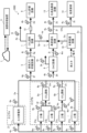
- FIG. 1 is a configuration diagram of a carbon management system 100 according to the first embodiment.
- the carbon management system 100 has a plurality of emission sources (in the example of FIG. 1, a thermal power plant 21 and factories 31a to 31n) that emit exhaust gas containing CO 2 (carbon dioxide), and A CO 2 recovery facility 1 that accumulates exhaust gas and separates and recovers CO 2 from the accumulated exhaust gas, conduits 2a to 2c that guide exhaust gas discharged from a plurality of emission sources to the CO 2 recovery facility 1, and a plurality of conduits 2a to 2c.
- It includes an arithmetic processing device 3 that sets an operation plan (operating condition) for at least one of the emission sources or an operation plan (operating condition) for the CO 2 recovery equipment 1.
- the plurality of emission sources include, for example, an emission source that emits a large amount and high concentration of CO 2 and an emission source that emits a lower concentration or a smaller amount of CO 2 than this emission source.
- Area A has an emission source that emits a large amount of CO 2 at a high concentration.
- a thermal power plant 21 is provided as such an emission source. Examples of the thermal power plant 21 include a gas-fired power plant, a coal-fired power plant, and a steel plant.
- the conduits 2a to 2c are provided between the emission sources and the CO 2 recovery equipment 1, and are configured so that the exhaust gases discharged from the plurality of emission sources are collected in the CO 2 recovery equipment 1.
- Area B which has facilities equipped with emission sources that have lower concentrations of CO 2 and lower emissions than the emission sources in Area A.
- area B may include an industrial area or an industrial cluster area.
- Area B includes factories 31a to 31n. Examples of industries in these factories 31a to 31n include chemical product manufacturing, food processing, steel, and cement industries.
- Each of the factories 31a to 31n in area B is connected to a conduit 2b. Then, the exhaust gas discharged from each of the factories 31a to 31n and the exhaust gas discharged from the thermal power plant 21 flow through the conduit 2b and the conduit 2a, respectively, and join together at the conduit 2c, and the combined exhaust gas flows through the conduit 2c. It is designed to be guided to the CO 2 recovery equipment 1. That is, exhaust gas discharged from area A and area B is supplied to the CO 2 recovery facility 1 via the conduits 2a and 2b.
- a transport vehicle (not shown) can also be used to supply the exhaust gas.
- the CO 2 recovery equipment 1 may be installed at a site different from the emission source, or may be installed at the same site (inside a factory) as the emission source. That is, the CO 2 recovery facility 1 may be provided at a site where any of a plurality of emission sources is located.
- exhaust gas generated from multiple emission sources is collectively supplied to the CO 2 recovery equipment 1 and CO 2 is separated and recovered, thereby reducing the cost burden associated with reducing CO 2 emissions. It becomes possible to do so. Furthermore, for those who own the CO 2 recovery equipment 1, the operating rate of the CO 2 recovery equipment 1 can be improved.
- carbon detectors 4a to 4i capable of measuring the concentration of carbon-containing components in the exhaust gas in terms of carbon and the flow rate of the exhaust gas are provided at predetermined locations of the conduits 2a to 2e.
- the carbon detection units 4a to 4e are installed near the exits of exhaust gas generation sources (thermal power plant 21 and factories 31a to 31n), respectively.
- the carbon detection unit 4f is installed at a point where the outlet pipes of the factories 31a and 31b, which are the exhaust gas generation sources in the area B, merge.
- the carbon detection unit 4g is installed near the entrance of the CO 2 recovery equipment 1 (a place where the combined exhaust gas flows).
- the "first detection section” that obtains the carbon-equivalent concentration of carbon-containing components in the exhaust gas emitted from the emission source (hereinafter referred to as carbon concentration) and the exhaust gas flow rate includes the carbon detection sections 4a to 4g. It is composed of:
- the carbon detection unit 4h shown in FIG. 1 is installed in the CO 2 conduit 2 d flowing out from the CO 2 recovery equipment 1. Further, the carbon detection unit 4i is installed in a conduit 2e (outlet gas conduit) through which gas other than CO 2 flows out from the CO 2 recovery equipment 1. Note that the "second detection section" that obtains the carbon-equivalent concentration and gas flow rate of the carbon-containing component in the gas discharged from the CO 2 recovery equipment 1 includes carbon detection sections 4h and 4i.
- Carbon-containing components in the exhaust gas include CO 2 , CO, and CH 4 .
- a method for measuring carbon-containing components in exhaust gas it is possible to use, for example, mass spectrometry, gas chromatography, infrared spectroscopy, cavity ring-down spectroscopy, or the like.
- the exhaust gas flow rate can be detected using a process gas flow meter or the like.
- the concentration and flow rate of these carbon components may be calculated based on the amount of fuel used by the exhaust gas generation source.
- Information from the carbon detection units 4a to 4i is aggregated into a data collection system 7 (database) via a network (not shown).
- the arithmetic processing device 3 of the carbon management system 100 is capable of communicating with the data collection system 7 via a network (not shown).
- the arithmetic processing unit 3 uses information from the carbon detection units 4a to 4i collected in the data collection system 7 to set an operation plan for the CO 2 recovery equipment 1 and each emission source. That is, the arithmetic processing device 3 detects at least one of the plurality of emission sources or CO 2 A calculation processing function for setting operating conditions of the CO 2 recovery equipment 1 , and a management function for managing at least one of the plurality of emission sources and the CO 2 recovery equipment 1 .
- FIG. 2 is a flowchart showing processing in the carbon management system (see also FIG. 1 as appropriate). Although not particularly shown in FIG. 2, there is an “accumulation process” in which exhaust gas discharged from multiple emission sources via conduits 2a to 2c is accumulated in the CO 2 recovery equipment 1, and a process in which the CO 2 recovery equipment 1 is It is assumed that a “separation process” is being performed to separate CO 2 from the accumulated exhaust gas.
- Step S101 The arithmetic processing device 3 collects data of a CO 2 emission plan from each area in a predetermined period. For example, the arithmetic processing device 3 sets the predetermined period to be one month, and manages the amount of CO 2 discharged and the amount of CO 2 recovered on a daily basis.
- the exhaust gas generation sources ie, the thermal power plant 21 in area A and the factories 31a to 31n in area B in FIG. 1 transmit data of the daily CO 2 emission plan to the processing unit 3. Then, the arithmetic processing device 3 registers the daily CO 2 emission amount and CO 2 recovery amount at the exhaust gas generation source.
- the processing unit 3 calculates the total value of the daily CO 2 emission plans of all the exhaust gas generation sources. This is the planned initial value of the amount of CO 2 recovered by recovery equipment 1.
- Step S102 The processing unit 3 determines whether the amount of CO 2 recovered in the CO 2 recovery facility 1 (for example, the amount recovered per day) exceeds a predetermined upper limit. If the amount of CO 2 recovered does not exceed the upper limit in step S102 (S102: No), the process of the arithmetic processing unit 3 returns to "START". Further, if the amount of CO 2 recovered exceeds the upper limit value in step S102 (S102: Yes), the processing of the arithmetic processing device 3 proceeds to step S103.
- the amount of CO 2 recovered in the CO 2 recovery facility 1 for example, the amount recovered per day
- Step S103 The processing unit 3 instructs to review the CO 2 emissions plan. For example, in the management function of the emission source and the CO 2 recovery equipment 1, the processing unit 3 controls the period during which this planned initial value exceeds the design upper limit value of the amount of CO 2 that can be recovered by the CO 2 recovery equipment 1 (time in FIG. 3A). t1 to t2), the exhaust gas generating source is instructed to review the CO 2 emission plan for the period (time t1 to t2) in which the upper limit value is exceeded. That is, the processing unit 3 transmits a predetermined instruction signal regarding the review of the CO 2 emission plan to the thermal power plant 21 and the factories 31a to 31n.
- the thermal power plant 21 and factories 31a to 31n in each area reset the CO 2 emissions plan based on the instructions from the processing unit 3 (S103), and calculate the data of the reset CO 2 emissions plan. It is transmitted to the processing device 3.
- the processing unit 3 acquires the data of the CO 2 emissions plan again (S101). As a result, the reset CO 2 emissions plan is re-registered in the arithmetic processing unit 3.
- the arithmetic processing unit 3 in its arithmetic processing function for setting operating conditions, again compiles the daily CO 2 emission plans for all exhaust gas generation sources.
- the management function of the emission source and the CO 2 recovery equipment 1 if it is determined that the amount of CO 2 recovered by the CO 2 recovery equipment during a predetermined period does not exceed the design upper limit (upper limit value) (S103: No), calculation processing is performed.
- the device 3 determines that the CO 2 recovery equipment 1 is ready for operation, and proceeds to the process of step S104.
- Step S104 The arithmetic processing device 3 sets operating conditions for the CO 2 recovery equipment 1 (arithmetic processing).
- the arithmetic processing unit 3 measures the amount of CO 2 emitted from the carbon detection units 4a to 4e provided in the conduits 2a and 2b of the exhaust gas generation source, and For each of 4e to 4e, calculate the difference from the reset plan value.
- the arithmetic processing unit 3 determines that the detected value of CO 2 emissions exceeds the re-planned value, it identifies the carbon detection unit that caused it to exceed the planned value, although it is omitted in FIG. A further reduction in the amount of CO 2 emitted and the amount of the reduction are notified to the exhaust gas generation source that is the source of the carbon detection unit.
- the detected value of the CO 2 recovery amount in the calculation processing function that sets the operating conditions of the CO 2 recovery equipment 1 is based on the CO 2 concentration in the exhaust gas and the exhaust gas amount of the carbon detection units 4g and 4h shown in FIG. Calculated from measured values.
- CO 2 recovery amount (exhaust gas amount of carbon detection unit 4g x CO 2 concentration of carbon detection unit 4g) - (exhaust gas amount of carbon detection unit 4i x CO 2 concentration of carbon detection unit 4i), or CO 2
- the amount of recovery is obtained as follows: (amount of exhaust gas from the carbon detection section 4h x CO 2 concentration of the carbon detection section 4h).
- the exhaust gas generation source that has been notified of the reduction in the amount of CO 2 emissions and the reduction amount executes the reduction in the amount of CO 2 emissions.
- the arithmetic processing unit 3 confirms whether or not this exhaust gas generation source has reduced the amount of CO 2 emissions based on the information from the carbon detection unit. In this way, the arithmetic processing device 3 calculates the amount of CO supplied to the CO 2 recovery equipment 1 from a plurality of emission sources based on the carbon concentration and exhaust gas flow rate acquired by the carbon detection units 4a to 4g (first detection unit). 2 Calculate the supply amount, and calculate the reduction amount of CO 2 emissions emitted from the emission source so that the CO 2 supply amount supplied to the CO 2 recovery equipment 1 falls within the design value of the CO 2 recovery equipment 1. .
- FIG. 3A is an explanatory diagram of a CO 2 emissions plan when it is predicted that the upper limit of the CO 2 recovery amount in the CO 2 recovery facility will be temporarily exceeded.
- a total of five graphs included in FIG. 3A in order from the top, show changes in CO 2 emissions at the thermal power plant 21 in area A, changes in CO 2 emissions at factories 31a, 31b, and 31n, and 2 shows the transition of the predicted value of CO 2 recovery amount in recovery equipment 1.
- the total amount of CO 2 emissions from the thermal power plant 21 and factories 31a, 31b, and 31n at each time is the amount of CO 2 recovered by the CO 2 recovery equipment 1.
- it is predicted that the CO 2 recovery amount in the CO 2 recovery facility 1 will exceed the predetermined upper limit Q0 during the time period from time t1 to t2.
- FIG. 3B is an explanatory diagram of the CO 2 emissions plan after the CO 2 emissions plan has been reviewed.
- the CO 2 emission plan is reviewed in the factories 31a and 31b, and the CO 2 emission plan for the time period including time t1 to t2 is Emissions are reduced.
- the CO 2 recovery amount (replanned value) in the CO 2 recovery equipment 1 is suppressed to a predetermined upper limit value Q0 or less.
- FIG. 3C is an explanatory diagram regarding actual CO 2 emissions. Note that the thick lines in each graph in FIG. 3 indicate the detected values of the amount of CO 2 discharged and the amount of CO 2 recovered. As described above, when the arithmetic processing unit 3 determines that the detected value of CO 2 emissions for each emission source exceeds the re-planned value, it notifies the further reduction of the amount of CO 2 emissions and the amount of the reduction. do.
- the carbon management system 100 collects exhaust gas discharged from a plurality of emission sources through the conduits 2a to 2g, and performs CO2 recovery that separates CO2 from the collected exhaust gas. It is equipped with an arithmetic processing device 3 that communicates with the equipment 1.
- the processing unit 3 sets operating conditions for at least one of the plurality of emission sources or operating conditions for the CO 2 recovery equipment. According to such a configuration, the processing unit 3 determines whether or not to adjust the amount of CO 2 emissions from the emission source based on the design upper limit value of the CO 2 recovery equipment 1 and the CO 2 emission plan of the emission source. , it is possible to give instructions to emission sources to reduce CO 2 emissions.
- CO 2 reduction can be achieved by consolidating exhaust gas in industrial clusters and collecting it all at once.
- the cost burden related to the introduction of reduction technology can be distributed.
- By keeping the CO 2 supply amount of the CO 2 recovery equipment 1, recycling equipment, etc. within the design range and adjusting the supply and demand it is possible to reduce the operational load and also ensure product purity and the balance between supply and demand.
- carbon-containing substances also include CO 2 .
- the second embodiment differs from the first embodiment in that an exhaust gas storage facility (see FIG. 4) is provided between the plurality of emission sources and the CO 2 recovery facility 1 (see FIG. 4). Further, the second embodiment differs from the first embodiment in that a DAC equipment 6 (see FIG. 4) is provided. Note that other aspects are the same as those in the first embodiment. Therefore, the parts that are different from the first embodiment will be explained, and the explanation of the overlapping parts will be omitted.
- FIG. 4 is a configuration diagram of a carbon management system 100A according to the second embodiment.
- the CO 2 emission plan can be changed without changing the CO 2 emission plan.
- a method for controlling the amount of CO 2 supplied so that the amount of CO 2 recovered by the recovery equipment 1 is suppressed below the upper limit will be described.
- the installation location further includes an arbitrary DAC (Direct Air Capture) equipment 6.
- DAC Direct Air Capture
- the exhaust gas storage facility 5 has a function of storing exhaust gas from emission sources such as the thermal power plant 21 and the factories 31a to 31n.
- the amount of exhaust gas stored in the exhaust gas storage facility 5 has a predetermined upper limit, and is managed so as not to exceed the upper limit.
- the amount of exhaust gas present in the exhaust gas storage facility 5 is calculated based on the relationship between the supply amount and release amount of exhaust gas in the exhaust gas storage facility 5, as well as the internal pressure of the exhaust gas storage facility 5. ing.
- the exhaust gas storage facility 5 is connected to a conduit 2f where exhaust gas from each CO 2 emission source joins.
- the exhaust gas stored in the exhaust gas storage facility 5 is led to the CO 2 recovery facility 1 via the conduit 2g.
- exhaust gas storage equipment may be installed separately after each emission source, and the installation location and number of installation equipment are not limited. Further, the conduit itself connecting the emission source and the CO 2 recovery equipment 1 may be regarded as the exhaust gas storage equipment, and the equipment form is not particularly limited.
- the DAC equipment 6 has a function of recovering CO 2 from the atmosphere.
- the recovery method of the DAC equipment 6 may be the same as that of the CO 2 recovery equipment 1.
- CO 2 recovery methods include chemical absorption methods in which CO 2 in the exhaust gas is absorbed into the CO 2 absorption solution by bringing the exhaust gas into contact with an alkaline CO 2 absorption solution, as well as adsorption methods using van der Waals forces.
- the conduit 2h on the inlet side of the DAC equipment 6 may be connected to, for example, any one of the conduits 2a to 2g, or may be connected to another predetermined location.
- the carbon management system 100A is capable of measuring the carbon-equivalent concentration of carbon-containing components in exhaust gas and the exhaust gas flow rate, in addition to the carbon detection units 4a to 4i described in the first embodiment. It further includes carbon detection units 4j to 4n.
- the carbon detection unit 4j is installed in the conduit 2g on the exit side of the exhaust gas storage facility 5.
- the carbon detection unit 4k is installed in the conduit 2h on the inlet side of the DAC equipment 6.
- the carbon detection unit 4m is installed in a conduit 2i that guides recovered CO 2 flowing out from the DAC equipment 6.
- the carbon detection unit 4n is installed in a conduit 2k (outlet gas conduit) that guides gas other than recovered CO 2 flowing out from the DAC equipment 6.
- the data detected by these carbon detectors 4a to 4n is collected into a data collection system 7 connected to the arithmetic processing device 3, as in the first embodiment.
- FIG. 5 is a flowchart showing processing in the carbon management system (see also FIG. 4 as appropriate). Note that steps S201, S202, and S204 in FIG. 5 are the same as steps S101, S102, and S104 in the first embodiment (see FIG. 2) in this order.
- Step S201 The processing unit 3 collects CO 2 emission plans from each area in a predetermined period. For example, the arithmetic processing device 3 sets the predetermined period to be one month, and manages the amount of CO 2 discharged and the amount of CO 2 recovered on a daily basis.
- the exhaust gas generation sources ie, the thermal power plant 21 in area A and the factories 31a to 31n in area B in FIG. 4) transmit data of the daily CO 2 emission plan to the processing unit 3. Then, the arithmetic processing device 3 registers the daily CO 2 emission amount and CO 2 recovery amount at the exhaust gas generation source.
- the processing unit 3 calculates the total value of the daily CO 2 emission plan of all the exhaust gas generation sources. 2 This is the planned initial value of the CO 2 recovery amount at recovery equipment 1.
- Step S202 The processing unit 3 determines whether the amount of CO 2 recovered in the CO 2 recovery facility 1 (for example, the amount recovered per day) exceeds a predetermined upper limit. If the amount of CO 2 recovered does not exceed the upper limit in step S202 (S202: No), the processing of the arithmetic processing unit 3 returns to "START". Further, if the amount of CO 2 recovered exceeds the upper limit value in step S202 (S202: Yes), the processing of the arithmetic processing unit 3 proceeds to step S203.
- the amount of CO 2 recovered in the CO 2 recovery facility 1 for example, the amount recovered per day
- Step S203 The arithmetic processing unit 3 instructs the exhaust gas storage facility 5 to store the amount of exhaust gas.
- the arithmetic processing unit 3 performs a period during which the planned initial value of the CO 2 recovery equipment 1 exceeds the upper limit of the amount of CO 2 that can be collected by the CO 2 collection equipment 1 (time t1 in FIG. 4). ⁇ t2) (S202: Yes), the exhaust gas storage equipment 5 is instructed to store the exhaust gas so that it falls within the upper limit (S203).
- the processing unit 3 transmits a predetermined instruction signal to the exhaust gas storage facility 5 requesting a review of the amount of CO 2 stored.
- the arithmetic processing unit 3 acquires the actual values of CO 2 emissions from the emission sources in each area from the carbon detection units 4a to 4n, and Exhaust gas is supplied to the exhaust gas storage facility 5 in accordance with operating conditions. At this time, if the amount of exhaust gas from the emission source increases or decreases from the plan based on the data from the carbon detection units 4b, 4c, 4d, and 4e, the arithmetic processing unit 3 stores the exhaust gas as appropriate according to the increase or decrease. Change the operation plan for equipment 5. In addition, during the time period when the planned initial value of the CO 2 recovery equipment 1 is below the design upper limit (t ⁇ t1, t>t2 in FIG. 6A), the exhaust gas stored in the exhaust gas storage equipment 5 is transferred to the CO 2 recovery equipment 1. It may be supplied within a range that does not exceed the design upper limit of .
- the arithmetic processing unit 3 will control the amount of CO 2 that exceeds the design upper limit during the time period exceeding the upper limit.
- DAC equipment 6 is instructed to recover CO 2 .
- the DAC equipment 6 recovers CO 2 according to the plan, but when the amount of exhaust gas from the emission source is larger than the plan, the operating conditions of the DAC equipment 6 are changed as appropriate. Note that during this time period (t1 to t2 in FIG. 6A), exhaust gas exceeding the design value may not be supplied to the CO 2 recovery equipment 1, but may be released into the atmosphere, for example.
- the CO 2 recovery equipment 1 and the DAC equipment 6 may be equipped with, for example, CO 2 storage equipment or CO 2 recycling equipment at the subsequent stage, so it is better to keep the amount of CO 2 recovered as constant as possible. Equipment operation becomes easier. Therefore, it is preferable to set the operating time of the DAC equipment 6 to a period other than the time period (t1 to t2) in FIG. 6A, which will be described next.
- FIG. 6A is an explanatory diagram of a CO 2 emissions plan when it is predicted that the upper limit of the CO 2 recovery amount in the CO 2 recovery facility will be temporarily exceeded. Note that FIG. 6A is similar to FIG. 3A used in the description of the first embodiment, and in the CO 2 recovery equipment 1, the CO 2 recovery amount exceeds the predetermined upper limit Q0 in the time period from time t1 to t2. is predicted. In such a case, the processing unit 3 transmits a predetermined instruction signal to the exhaust gas storage facility 5 so that the amount of CO 2 recovered at each time is suppressed to below the upper limit value Q0.
- FIG. 6B is an explanatory diagram after the CO 2 storage amount has been reviewed. As shown in FIG. 6B, by adjusting the amount of CO 2 stored at each time in the exhaust gas storage equipment 5, the amount of CO 2 recovered in the CO 2 recovery equipment 1 is suppressed below the upper limit value Q0, and It is trending around Q0. Note that the thermal power plant 21 in Area A and the factories 31a to 31n in Area B can operate without any particular changes to the original CO 2 emission plan (see FIG. 6A).
- FIG. 6C is an explanatory diagram showing another example after the CO 2 storage amount has been reviewed.
- the CO 2 recovery amount in the CO 2 recovery equipment 1 exceeds the predetermined upper limit Q0 during the time period t1 to t2.
- the remaining amount is stored in the exhaust gas storage facility 5. Even with such processing, the amount of CO 2 recovered in the CO 2 recovery equipment 1 can be suppressed to below the upper limit value Q0.
- the detected value of the CO 2 storage amount in the arithmetic processing function that sets the operating conditions of the exhaust gas storage equipment 5 is based on the measured values of the CO 2 concentration in the gas and the gas amount of the carbon detection units 4g and 4j in FIG. Calculated.
- CO 2 storage amount (gas amount of carbon detection section 4g x CO 2 concentration of carbon detection section 4g) - (gas amount of carbon detection section 4j x CO 2 concentration of carbon detection section 4j), exhaust gas storage equipment A CO 2 storage amount of 5 is obtained.
- the amount of CO 2 stored in the exhaust gas storage equipment 5 can also be calculated by a method that does not use a carbon detection unit, for example, based on the detected value of a pressure gauge (not shown) provided in the exhaust gas storage equipment 5. It is.
- the processing unit 3 calculates the amount of CO 2 supplied from the plurality of emission sources to the CO 2 recovery equipment 1 based on the carbon concentration and exhaust gas flow rate acquired by the carbon detection units 4a to 4g (first detection unit). . Then, when the CO 2 recovery amount exceeds the design value (upper limit) of the CO 2 recovery equipment 1, the arithmetic processing unit 3 stores the exhaust gas in excess of this design value into the exhaust gas storage equipment 5 (exhaust gas storage means). ) to be temporarily stored. Thereafter, when the CO 2 supply amount becomes less than the design value of the CO 2 recovery equipment 1 , the processing unit 3 extracts exhaust gas from the exhaust gas storage equipment 5 within a range that does not exceed the design value of the CO 2 recovery equipment 1 . The operating conditions of the exhaust gas storage equipment 5 are set so that the exhaust gas storage equipment 5 is supplied to the CO 2 recovery equipment 1.
- the detected value of the CO 2 recovery amount in the arithmetic processing function that sets the operating conditions of the DAC equipment 6 is obtained from the measured values of the CO 2 concentration in the gas and the gas amount of the carbon detection units 4k, 4m, and 4n in FIG. Calculated.
- the processing unit 3 calculates the amount of CO 2 supplied from the plurality of emission sources to the CO 2 recovery equipment 1 based on the carbon concentration and exhaust gas flow rate acquired by the carbon detection units 4a to 4g (first detection unit). . Then, when the CO 2 supply amount exceeds the design value (upper limit) of the CO 2 recovery equipment 1, the arithmetic processing unit 3 extracts exhaust gas from multiple emission sources in an amount equal to the design value of the CO 2 recovery equipment 1. Supplied to CO 2 recovery equipment 1. Furthermore, the processing unit 3 calculates the surplus CO 2 amount exceeding the design value of the CO 2 recovery equipment 1 from the CO 2 supply amount and the design value, and sets the operating conditions of the DAC equipment 6 so as to recover the surplus CO 2 amount. Set.
- the second embodiment a control method for a case where the emission source in each area cannot flexibly change the CO 2 emission plan has been described, but the control method is not limited to this.
- the second embodiment can be applied even in a case where the emission source in each area can change the CO 2 emission plan as in the first embodiment, and the conditions are not limited.
- the third embodiment is characterized in that CO 2 concentration equipment 8a, 8b (CO 2 concentration adjustment equipment: see FIG. 7) is provided between the plurality of emission sources and the exhaust gas storage equipment 5 (see FIG. 7).
- CO 2 concentration equipment 8a, 8b CO 2 concentration adjustment equipment: see FIG. 7
- This is different from the second embodiment. Note that other aspects are the same as those in the second embodiment. Therefore, portions that are different from the second embodiment will be described, and descriptions of overlapping portions will be omitted.
- FIG. 7 is a configuration diagram of a carbon management system 100B according to the third embodiment.
- CO 2 recovery equipment 1 (see Figure 7) is designed assuming the CO 2 concentration of the gas supplied from the inlet, and if the CO 2 concentration in the supplied gas falls below that, CO 2 recovery There is a possibility that the energy consumption when separating CO 2 in the equipment 1 increases, or the concentration of recovered CO 2 at the outlet decreases. Further, if the amount of exhaust gas from the emission source is large, the conduit connecting the emission source in each area and the CO 2 recovery equipment 1 or the exhaust gas storage equipment 5 needs to be designed to be large.
- FIG. 7 shows CO 2 concentration equipment 8a, 8b (CO 2 It is also equipped with concentration adjustment equipment). Note that the configurations and connection forms of elements other than the CO 2 concentration equipment 8a and 8b are the same as in the second embodiment. Furthermore, since the method for controlling the amount of CO 2 supplied to the CO 2 recovery equipment 1 to be equal to or less than the design upper limit value of the CO 2 recovery equipment 1 is the same as in the second embodiment, the explanation will be omitted.
- the CO 2 concentration equipment 8a, 8b is equipment that adjusts the CO 2 concentration of exhaust gas discharged from at least one of a plurality of emission sources (in the example of FIG. 7, factories 31a, 31b, 31c), and It is provided between the emission source and the CO 2 recovery equipment 1.
- These CO 2 concentration facilities 8a and 8b have a function of increasing the CO 2 concentration in the exhaust gas.
- CO 2 separation membranes can be used to remove CO 2 .
- One method is to separate CO2 and combine it with exhaust gas from other emission sources to increase the CO2 concentration.
- a conduit (not shown) that separates CO 2 with a CO 2 separation membrane and bypasses one CO 2 concentration equipment is also available. ), the bypassed exhaust gas and concentrated CO 2 gas may be combined to adjust the CO 2 concentration.
- a carbon detection unit 4p is installed in the conduit 2m downstream of the CO 2 concentration equipment 8a, and a carbon detection unit 4q is installed in the conduit 2n downstream of the CO 2 concentration equipment 8b.
- the carbon detection units 4p and 4q have a function of measuring the carbon-equivalent concentration of carbon-containing components in the gas and the exhaust gas flow rate.
- the data detected by these carbon detectors 4p and 4q is collected into a data collection system 7 connected to the arithmetic processing device 3, as in the first and second embodiments.
- FIG. 8 is a flowchart showing processing in the carbon management system (see also FIG. 7 as appropriate). Note that steps S301 and S304 in FIG. 8 are the same as steps S101 and S104 in the first embodiment (see FIG. 2) in this order.
- the arithmetic processing unit 3 performs the arithmetic processing function for setting the operating conditions of the CO 2 concentration equipment 8a, 8b based on the amount of CO 2 recovered and the exhaust gas flow rate collected from each exhaust gas generation source in the CO 2 recovery equipment 1. Therefore, the CO 2 concentration at the entrance of the CO 2 recovery equipment 1 is set as the planned initial value.
- Step S303 The arithmetic processing device 3 transmits a predetermined operation instruction to the CO 2 concentration equipment 8a, 8b. That is, the arithmetic processing device 3 transmits an operation instruction to the CO 2 concentration equipment 8a, 8b so that the CO 2 concentration exceeds the design CO 2 concentration of the CO 2 recovery equipment 1. At this time, it is sufficient that the CO 2 concentration is at least the design CO 2 concentration at the inlet side of the CO 2 recovery equipment 1, and there is no particular need for the design CO 2 concentration to be at least the design CO 2 concentration at the outlet sides of all the CO 2 concentration equipment 8a, 8b. .
- the exhaust gas generation source and exhaust gas storage equipment 5 are In addition, predetermined operating conditions based on each management function of the arithmetic processing device 3 may be instructed to the DAC equipment 6.
- the arithmetic processing unit 3 determines, based on the data from the carbon detection units 4b, 4c, 4d, and 4e, if the actual values of the exhaust gas amount from the emission source and the CO 2 concentration increase or decrease from the planned values, Depending on the increase or decrease, the operating conditions of the CO 2 concentration equipment 8a, 8b are changed as appropriate so that the CO 2 concentration on the inlet side of the CO 2 recovery equipment 1 becomes equal to or higher than the design value (design CO 2 concentration).
- the arithmetic processing device 3 determines that the carbon concentration in the exhaust gas supplied to the CO 2 recovery equipment 1 is within the set numerical value range based on the carbon concentration acquired by the carbon detection units 4a to 4g (first detection unit).
- the operating conditions of the CO 2 concentration equipment 8a, 8b (CO 2 concentration adjustment equipment) are set so that
- FIG. 9A is an explanatory diagram showing changes in predicted values of CO 2 emissions and CO 2 concentration of a thermal power plant in Area A.
- the CO 2 emissions of the thermal power plant 21 in area A will increase and then begin to decrease.
- the concentration of CO 2 discharged from the thermal power plant 21 will exceed the design concentration of the CO 2 recovery equipment 1.
- FIG. 9B is an explanatory diagram showing changes in predicted values of CO 2 emissions and CO 2 concentrations of factories 31a, 31b, and 31n in area B. As shown in FIG. 9B, it is predicted that the CO 2 emissions of the factories 31a, 31b, and 31c (see FIG. 7) in area B will increase or decrease in a predetermined manner. In addition, the concentration of CO 2 discharged from the factory 31n exceeds the design concentration of the CO 2 recovery equipment 1, but the concentration of CO 2 discharged from the factories 31a and 31b exceeds the design concentration of the CO 2 recovery equipment 1. It is predicted that it will fall below.
- FIG. 9C is an explanatory diagram showing changes in the CO 2 recovery amount and CO 2 concentration in the CO 2 recovery equipment.
- the amount of CO 2 recovered in the CO 2 recovery equipment 1 will exceed the predetermined upper limit Q0 during the time period from time t1 to time t2.
- the CO 2 concentration in the CO 2 recovery facility 1 will be lower than a predetermined design concentration.
- FIG. 9D is an explanatory diagram showing changes in predicted values of CO 2 emissions and CO 2 concentration of the thermal power plant in area A when the CO 2 concentration equipment is operated.
- the thermal power plant 21 in area A see FIG. 7
- the CO 2 concentration has exceeded the design concentration of the CO 2 recovery equipment 1 from the beginning, so the CO 2 emission plan is not particularly changed.
- FIG. 9E is an explanatory diagram showing changes in predicted values of CO 2 emissions and CO 2 concentrations of factories 31a, 31b, and 31n in area B when the CO 2 concentration equipment is operated.
- the CO 2 emissions are reduced in the factories 31a and 31b so that the CO 2 recovery amount in the CO 2 recovery equipment 1 is suppressed to the upper limit Q0 or less in the time period including time t1 to t2 (see FIG. 9C). is being reviewed.
- the CO 2 concentration equipment 8a, 8b see Figure 7 as specified, the concentration of CO 2 discharged from the factories 31a, 31b in addition to the factory 31n will also exceed the design concentration of the CO 2 recovery equipment. is predicted.
- the processing unit 3 measures and manages the CO 2 concentration using carbon detection units 4p and 4q installed on the exit sides of the CO 2 concentrators 8a and 8b, and changes the operating conditions of the CO 2 concentrators 8a and 8b.
- a carbon detection unit (not shown) may be provided in an outlet gas conduit (not shown) connected to the CO 2 concentration equipment 8a, 8b and through which gas other than concentrated CO 2 flows. Then, the carbon detection unit installed in the outlet gas pipe detects the gas amount and CO 2 concentration, and based on the detected values, the processing unit 3 adjusts the operating conditions of the CO 2 concentration equipment 8a, 8b as appropriate. It may be updated.
- the concentration reduces the flow rate of exhaust gas from the exhaust gas generation source, it also contributes to reducing the initial cost of the conduit.
- a carbon management system 100C includes a CO 2 storage facility 9 (see FIG. 10), a hydrogen production facility 10 (see FIG. 10), and a recycling facility 11 (see FIG. 10).
- This embodiment differs from the third embodiment (see FIG. 7) in that it includes a CO 2 storage flow rate adjustment means 12 (see FIG. 10). Note that the other aspects are the same as those in the third embodiment. Therefore, the parts that are different from the third embodiment will be explained, and the explanation of the overlapping parts will be omitted.
- FIG. 10 is a configuration diagram of a carbon management system 100C according to the fourth embodiment.
- the carbon management system 100C shown in FIG. 10 includes a CO 2 storage facility 9, a hydrogen production facility 10, a recycling facility 11, and a CO 2
- the storage flow rate adjusting means 12 is provided.
- the CO 2 storage facility 9 is a facility that stores CO 2 supplied from the CO 2 recovery facility 1 and is provided downstream of the CO 2 recovery facility 1 .
- the substances to be recycled by the recycling equipment 11 include, for example, methane and ethanol, but they vary widely depending on the consumer. In the fourth embodiment, this is described as “fuel” or “resource,” but the number of types of substances may be one or more.
- the "third detection section” that acquires the carbon-equivalent concentration and gas flow rate of carbon-containing components in the gas supplied from the recycling equipment 11 to at least one of the plurality of emission sources is the carbon detection section 4s to 4s. 4z.
- the arithmetic processing unit 3 calculates the amount of combustion or resources used in exhaust gas generation sources, chemical product manufacturing, etc. from the data of the carbon detection units 4s to 4z acquired by the data collection system 7, and uses the information to calculate the amount of combustion or resources used in the production of chemical products.
- the amount of CO 2 supplied to the oxidation equipment 11 is calculated.
- the arithmetic processing unit 3 determines the amount of fuel used at the emission source based on the carbon-equivalent concentration of the carbon-containing component in the gas and the gas flow rate obtained by the carbon detection units 4s to 4z (third detection unit). is calculated, and the amount of CO 2 supplied required by the recycling equipment 11 is calculated from the amount of fuel used at the emission source.
- the processing unit 3 calculates the CO 2 flow rate to be supplied to the CO 2 storage equipment 9 from the difference between the CO 2 recovery amount calculated from the data of the carbon detection unit 4j and the CO 2 supply amount to the recycling equipment 11. .
- the processing unit 3 determines the operating conditions of the CO 2 storage flow rate adjustment means 12 from the CO 2 supply amount to the recycling equipment 11 and the CO 2 supply amount to the CO 2 storage equipment 9, and determines the CO 2 storage flow rate adjustment unit 12. An instruction is given to the adjustment means 12. That is, the processing unit 3 sets the operating conditions for the CO 2 storage flow rate adjustment means 12 based on the difference between the amount of CO 2 recovered in the CO 2 recovery equipment 1 and the amount of CO 2 supplied by the recycling equipment 11.
- the processing unit 3 may set the operating conditions of the hydrogen production facility 10 based on the amount of renewable power supplied to the hydrogen production facility 10 and the demand for synthetic fuel.
- the resource recycling facility 11 can produce the amount of fuel or resources required by the exhaust gas generation source and other consumers. Further, according to the fourth embodiment, it is possible to adjust the supply and demand of all carbon-containing substances including not only CO 2 but also synthetic fuels that are recycled using CO 2 as a raw material.
- the fifth embodiment describes a method for supplying an appropriate amount of recycled fuel or resources to an exhaust gas generation source when the operating conditions of the exhaust gas generation source are changed and the amount of fuel or raw materials used changes. .
- fuels and resources are manufactured in the recycling equipment 11 (see FIG. 10), they are collectively referred to as "fuel" in the fifth embodiment.
- the configuration of the carbon management system according to the fifth embodiment is the same as that of the fourth embodiment (see FIG. 10), so descriptions of each configuration will be omitted.
- the processing unit 3 controls the DAC to supply the additional required amount of CO 2 to the recycling equipment 11.
- the operating conditions of equipment 6 are set.
- the arithmetic processing device 3 causes the DAC equipment 6 to supply the necessary amount of CO 2 to the recycling equipment 11 .
- the arithmetic processing unit 3 first detects the fuel obtained from the carbon detection units 4s to 4z (third detection unit).
- the CO 2 recycling equipment supply amount required by the recycling equipment 11 is calculated from the usage amount.
- the processing unit 3 selects additional CO 2 recycling equipment that is required.
- the operating conditions of the DAC equipment 6 that recovers CO 2 from the atmosphere are set so that the supplied amount is supplied to the recycling equipment 11 . Thereby, the fuel supply amount detected by the carbon detection unit 4s can be adjusted to match the fuel demand amount of the entire system.
- the supply amount of the recycled fuel produced by the recycling equipment 11 is further adjusted by the carbon detection units 4t to 4z so as to match the demand of each exhaust gas generation source or consumer.
- the DAC equipment 6 is mentioned as an additional amount of CO 2 needed to be supplied to the recycling equipment 11, but the required amount of CO 2 is supplied from a predetermined CO 2 storage equipment (not shown). Good too.
- the arithmetic processing unit 3 calculates the fuel demand of the entire system based on the data of the carbon detection units 4s to 4z acquired by the data collection system 7. Further, the processing unit 3 calculates the amount of recycled fuel that can be manufactured by the recycling equipment 11 from the amount of fuel used and the amount of carbon equivalent obtained from the carbon detectors 4a to 4f.
- the arithmetic processing unit 3 sets the operating conditions of the CO 2 storage flow rate adjustment means 12 and removes the excess CO 2 is stored in the CO 2 storage facility 9.
- the processing unit 3 calculates the amount of CO 2 necessary for the recycling equipment 11 from the amount of fuel used from the carbon detection units 4s to 4z (third detection unit).
- the recycling equipment supply amount is calculated, and the operating conditions of the CO 2 storage flow rate adjustment means 12 are set based on the difference between the CO 2 supply amount and the CO 2 recycling equipment supply amount.
- the CO 2 flow rate detected by the carbon detection unit 4h is determined by the difference between the amount of carbon detected by the carbon detection units 4a to 4f and the amount of carbon adjusted to match the demand for recycled fuel of the entire system. adjusted to match.
- the demand for recycled fuel in each area increases or decreases, it is possible to control the amount of CO 2 supplied to the recycling equipment 11 to an appropriate value.
- one or more computers such as a server (not shown) may execute all or part of the program that implements the functions (carbon management method) of the carbon management system 100 etc. described in each embodiment. You can. All or part of the program described above may be realized in hardware by designing an integrated circuit or the like. Further, the configurations and functions described in the embodiments may be realized by software by a processor interpreting and executing programs for realizing the respective functions. Information such as programs, tables, files, etc. that realize each function is stored in memory, hard disks, recording devices such as SSD (Solid State Drive), or recording media such as IC cards, SD cards, CD-ROMs, DVDs, etc. It is also possible to do so. The above-described program can also be provided via a communication line.
- SSD Solid State Drive
Landscapes
- Business, Economics & Management (AREA)
- Tourism & Hospitality (AREA)
- Health & Medical Sciences (AREA)
- Economics (AREA)
- General Health & Medical Sciences (AREA)
- Human Resources & Organizations (AREA)
- Marketing (AREA)
- Primary Health Care (AREA)
- Strategic Management (AREA)
- Physics & Mathematics (AREA)
- General Business, Economics & Management (AREA)
- General Physics & Mathematics (AREA)
- Engineering & Computer Science (AREA)
- Theoretical Computer Science (AREA)
- Treating Waste Gases (AREA)
- Carbon And Carbon Compounds (AREA)
Abstract
Provided is a carbon management system, etc., with which it is possible to adjust the supply/demand balance of CO2. This carbon management system (100) comprises a plurality of discharge sources that discharge a CO2-containing exhaust gas, a CO2 recovery facility (1) that separates and recovers CO2 from the exhaust gas discharged from the plurality of discharge sources, conduit tubes (2a to 2c) that are provided between the discharge sources and the CO2 recovery facility (1) so that the exhaust gas discharged from the plurality of discharge sources is collected in the CO2 recovery facility (1), and a computation processing device (3) that sets an operating condition for at least one of the plurality of discharge sources or an operating condition for the CO2 recovery facility (1).
Description
本発明は、炭素管理システム及び演算処理装置に関する。
The present invention relates to a carbon management system and an arithmetic processing device.
カーボンニュートラル社会を実現するために再エネ導入拡大、設備電動化が進められているが、IEA(International Energy Agency)の予測においても化石燃料を使用する設備は一定割合で残存する。そのためCO2削減技術導入は必須である。例えば、工場等から排出されるCO2の回収に関して、特許文献1,2に記載の技術が知られている。
In order to realize a carbon-neutral society, the introduction of renewable energy is being expanded and equipment is being electrified, but the International Energy Agency (IEA) predicts that a certain percentage of equipment that uses fossil fuels will remain. Therefore, the introduction of CO2 reduction technology is essential. For example, the techniques described in Patent Documents 1 and 2 are known regarding the recovery of CO 2 discharged from factories and the like.
すなわち、特許文献1には、CO2排出をコストに換算し、そのプロセスパスのコストを評価し、最適パスを提案するシステムが開示されている。
That is, Patent Document 1 discloses a system that converts CO 2 emissions into costs, evaluates the cost of the process path, and proposes an optimal path.
また、特許文献2には、CO2回収装置の使用者の識別情報やCO2回収量やその使用用途や使用量に関する情報等を、CO2収集スタンド、運搬車両、CO2燃料化等の処理工場および情報管理センターとの間で管理するための情報管理システムが開示されている。
Furthermore, Patent Document 2 describes the identification information of the user of the CO 2 recovery device, the amount of CO 2 recovered, and information regarding its intended use and amount, etc., at the CO 2 collection stand, transportation vehicle, processing of CO 2 fuel, etc. An information management system for managing between a factory and an information management center is disclosed.
特許文献1及び2には、CO2やCO2を含む炭素含有物質の需給バランスを考慮したCO2回収設備やCO2資源化設備の運用については開示されていない。複数の設備が接続される構想においては、主要な構成要素であるCO2回収設備やCO2資源化設備等を運用するためにはCO2、ないしは再資源化した炭素含有物質の需給バランスを調整するシステムが求められている。
Patent Documents 1 and 2 do not disclose the operation of CO 2 recovery equipment and CO 2 resource recovery equipment in consideration of the supply and demand balance of CO 2 and carbon-containing substances including CO 2 . In a concept where multiple facilities are connected, it is necessary to adjust the supply and demand balance of CO 2 or recycled carbon-containing materials in order to operate the main components such as CO 2 recovery equipment and CO 2 resource recovery equipment. There is a need for a system that does this.
そこで、本発明は、CO2又は炭素含有物質の需給バランスを調整可能な炭素管理システム等を提供することを課題とする。
Therefore, an object of the present invention is to provide a carbon management system and the like that can adjust the supply and demand balance of CO 2 or carbon-containing substances.
前記した課題を解決するために、本発明に係る炭素管理システムは、CO2を含む排気ガスを排出する複数の排出源と、前記複数の排出源から排出された排気ガスからCO2を分離回収するCO2回収設備と、前記複数の排出源から排出された排気ガスが前記CO2回収設備に集積されるように、前記排出源と前記CO2回収設備との間に設けられた導管と、前記複数の排出源の少なくとも一つの稼働条件又は前記CO2回収設備の稼働条件を設定する演算処理装置と、を備えることとした。
In order to solve the above-mentioned problems, the carbon management system according to the present invention includes a plurality of emission sources that emit exhaust gas containing CO2 , and a system that separates and recovers CO2 from the exhaust gas emitted from the plurality of emission sources. a conduit provided between the emission source and the CO 2 recovery equipment so that exhaust gas emitted from the plurality of emission sources is collected in the CO 2 recovery equipment ; and a processing device that sets operating conditions for at least one of the plurality of emission sources or operating conditions for the CO 2 recovery equipment.
本発明によれば、CO2又は炭素含有物質の需給バランスを調整可能な炭素管理システム等を提供できる。
According to the present invention, it is possible to provide a carbon management system and the like that can adjust the supply and demand balance of CO 2 or carbon-containing substances.
以下、本発明の各実施形態を、図面を用いて説明する。なお、同一の構成には、同一の符号を付し、説明が重複する場合は、その説明を省略する場合がある。また、本発明は、以下の各実施形態に限定されるものではない。
本発明の一実施形態に係る炭素管理システム100(図1参照)は、産業集積地等の複数のCO2を含む排気ガスを排出するエリアにおいてそれらの排気ガスを集約し、一括でCO2を回収し、その下流の設備に供給するように構成されている。これによって、CO2削減技術導入に係るコスト負担を分散できる他、各要素設備の負荷低減や需給管理を行うことができる。 Hereinafter, each embodiment of the present invention will be described using the drawings. Note that the same configurations are denoted by the same reference numerals, and if the description is repeated, the description may be omitted. Further, the present invention is not limited to the following embodiments.
A carbon management system 100 (see FIG. 1) according to an embodiment of the present invention aggregates a plurality of exhaust gases containing CO 2 in an area such as an industrial agglomeration area, and releases CO 2 all at once. It is configured to be collected and supplied to downstream equipment. This makes it possible to distribute the cost burden associated with the introduction of CO 2 reduction technology, as well as reduce the load on each elemental facility and manage supply and demand.
≪第1実施形態≫
図1は、第1実施形態に係る炭素管理システム100の構成図である。炭素管理システム100は、CO2(二酸化炭素)を含む排気ガスを排出する複数の排出源(図1の例では、火力発電所21や工場31a~31n)と、複数の排出源から排出された排気ガスを集積し、集積した排気ガスからCO2を分離回収するCO2回収設備1と、複数の排出源から排出された排気ガスをCO2回収設備1に導く導管2a~2cと、複数の排出源の少なくとも一つの稼働計画(稼働条件)又はCO2回収設備1の稼働計画(稼動条件)を設定する演算処理装置3と、を備える。複数の排出源は、例えば、多量かつ高濃度のCO2を排出する排出源と、この排出源よりも低濃度又は少量のCO2を排出する排出源と、を含む。エリアAには大量かつ高濃度のCO2を排出する排出源がある。このような排出源として、図1の例では、火力発電所21が設けられている。火力発電所21として、例えばガス火力発電所、石炭火力発電所や製鉄所などがある。導管2a~2cは、排出源とCO2回収設備1との間に設けられ、複数の排出源から排出された排気ガスがCO2回収設備1に集積されるように、構成されている。 ≪First embodiment≫
FIG. 1 is a configuration diagram of acarbon management system 100 according to the first embodiment. The carbon management system 100 has a plurality of emission sources (in the example of FIG. 1, a thermal power plant 21 and factories 31a to 31n) that emit exhaust gas containing CO 2 (carbon dioxide), and A CO 2 recovery facility 1 that accumulates exhaust gas and separates and recovers CO 2 from the accumulated exhaust gas, conduits 2a to 2c that guide exhaust gas discharged from a plurality of emission sources to the CO 2 recovery facility 1, and a plurality of conduits 2a to 2c. It includes an arithmetic processing device 3 that sets an operation plan (operating condition) for at least one of the emission sources or an operation plan (operating condition) for the CO 2 recovery equipment 1. The plurality of emission sources include, for example, an emission source that emits a large amount and high concentration of CO 2 and an emission source that emits a lower concentration or a smaller amount of CO 2 than this emission source. Area A has an emission source that emits a large amount of CO 2 at a high concentration. In the example of FIG. 1, a thermal power plant 21 is provided as such an emission source. Examples of the thermal power plant 21 include a gas-fired power plant, a coal-fired power plant, and a steel plant. The conduits 2a to 2c are provided between the emission sources and the CO 2 recovery equipment 1, and are configured so that the exhaust gases discharged from the plurality of emission sources are collected in the CO 2 recovery equipment 1.
図1は、第1実施形態に係る炭素管理システム100の構成図である。炭素管理システム100は、CO2(二酸化炭素)を含む排気ガスを排出する複数の排出源(図1の例では、火力発電所21や工場31a~31n)と、複数の排出源から排出された排気ガスを集積し、集積した排気ガスからCO2を分離回収するCO2回収設備1と、複数の排出源から排出された排気ガスをCO2回収設備1に導く導管2a~2cと、複数の排出源の少なくとも一つの稼働計画(稼働条件)又はCO2回収設備1の稼働計画(稼動条件)を設定する演算処理装置3と、を備える。複数の排出源は、例えば、多量かつ高濃度のCO2を排出する排出源と、この排出源よりも低濃度又は少量のCO2を排出する排出源と、を含む。エリアAには大量かつ高濃度のCO2を排出する排出源がある。このような排出源として、図1の例では、火力発電所21が設けられている。火力発電所21として、例えばガス火力発電所、石炭火力発電所や製鉄所などがある。導管2a~2cは、排出源とCO2回収設備1との間に設けられ、複数の排出源から排出された排気ガスがCO2回収設備1に集積されるように、構成されている。 ≪First embodiment≫
FIG. 1 is a configuration diagram of a
エリアAの近隣にエリアAの排出源より低濃度CO2かつ低排出量の排出源を備える設備が集まったエリアBがある。例えば、エリアBとして工業地帯や産業集積地などがある。エリアBの中には工場31a~31nがある。これらの工場31a~31nにおける業種としては、例えば化成品製造業や食品加工業、鉄鋼業、セメント業などが挙げられる。
Near Area A, there is Area B, which has facilities equipped with emission sources that have lower concentrations of CO 2 and lower emissions than the emission sources in Area A. For example, area B may include an industrial area or an industrial cluster area. Area B includes factories 31a to 31n. Examples of industries in these factories 31a to 31n include chemical product manufacturing, food processing, steel, and cement industries.
エリアB内の各工場31a~31nには、それぞれ、導管2bが接続されている。そして、各工場31a~31nから排出された排気ガスと、火力発電所21から排出された排気ガスと、がそれぞれ導管2b、導管2aを流れ、導管2cで合流し、合流した排気ガスが導管2cによりCO2回収設備1に導かれるようになっている。つまり、エリアAとエリアBから排出される排気ガスは導管2a,2bを介してCO2回収設備1へ供給される。なお、第1実施形態では、エリアA、BからCO2回収設備1に供給される排気ガスを導管2a,2bで供給する例を説明するが、CO2排出源からCO2回収設備1への排気ガスの供給には、例えば、運搬車両(図示せず)を用いることもできる。
Each of the factories 31a to 31n in area B is connected to a conduit 2b. Then, the exhaust gas discharged from each of the factories 31a to 31n and the exhaust gas discharged from the thermal power plant 21 flow through the conduit 2b and the conduit 2a, respectively, and join together at the conduit 2c, and the combined exhaust gas flows through the conduit 2c. It is designed to be guided to the CO 2 recovery equipment 1. That is, exhaust gas discharged from area A and area B is supplied to the CO 2 recovery facility 1 via the conduits 2a and 2b. In the first embodiment, an example will be described in which exhaust gas is supplied from areas A and B to the CO 2 recovery equipment 1 through conduits 2a and 2b. For example, a transport vehicle (not shown) can also be used to supply the exhaust gas.
CO2回収設備1は、排気ガス中のCO2を回収する機能を有する。CO2の回収方法として、例えば、アルカリ性のCO2吸収液と排気ガスを接触させて排気ガス中のCO2をCO2吸収液に吸収させる化学吸収方法がある。その他にも、ファンデルワールス力を利用した吸着剤による物理吸着法や、アルカリ性のCO2吸着材(固体)と排気ガスを接触させて排気ガス中のCO2をCO2吸着材に吸着させる化学吸着方法などがある。CO2回収設備1は、排出源とは別のサイトも設置されていてもよいし、排出源と同じサイト(工場内)に設置されていてもよい。すなわち、CO2回収設備1が、複数の排出源のいずれかが配置されているサイトに設けられていてもよい。
The CO 2 recovery equipment 1 has a function of recovering CO 2 in exhaust gas. As a CO 2 recovery method, for example, there is a chemical absorption method in which an alkaline CO 2 absorption liquid and exhaust gas are brought into contact with each other to absorb CO 2 in the exhaust gas into the CO 2 absorption liquid. In addition, there are physical adsorption methods using adsorbents that utilize van der Waals forces, and chemical methods in which CO 2 in the exhaust gas is adsorbed by the CO 2 adsorbent by bringing the exhaust gas into contact with an alkaline CO 2 adsorbent (solid). There are adsorption methods. The CO 2 recovery equipment 1 may be installed at a site different from the emission source, or may be installed at the same site (inside a factory) as the emission source. That is, the CO 2 recovery facility 1 may be provided at a site where any of a plurality of emission sources is located.
なお、図1の例では、エリアAから排出された排気ガスが流通する導管2aと、エリアBから排出された排気ガスが流通する導管2bとが、導管2cに接続することで合流した後に、CO2回収設備1へ排気ガスが供給される構成になっているが、これに限らない。例えば、エリアAからの排気ガスと、エリアBからの排気ガスと、がそれぞれ個別にCO2回収設備1へ供給されてもよい。なお、エリアAの導管2aと、エリアBの導管2bとは、CO2回収設備1の前段の導管2cで集合(合流)させた後にCO2回収設備1へ供給された方がCO2回収設備1へ供給されるCO2を一括管理できるため好ましい。
In the example of FIG. 1, after the conduit 2a through which exhaust gas discharged from area A flows and the conduit 2b through which exhaust gas discharged from area B flows are connected to conduit 2c and merge, Although the configuration is such that exhaust gas is supplied to the CO 2 recovery facility 1, the present invention is not limited to this. For example, the exhaust gas from area A and the exhaust gas from area B may be separately supplied to the CO 2 recovery facility 1. Note that the conduit 2a in area A and the conduit 2b in area B are combined (combined) in the conduit 2c at the front stage of the CO 2 recovery equipment 1, and then the CO 2 recovery equipment is supplied to the CO 2 recovery equipment 1. This is preferable because CO 2 supplied to 1 can be managed all at once.
第1実施形態のように、複数の排出源で発生した排気ガスをまとめてCO2回収設備1に供給し、CO2の分離回収を行うことにより、CO2排出量削減に係るコスト負担を低減することが可能となる。また、CO2回収設備1を保有している者にとっては、CO2回収設備1の稼働率を向上させることができる。
As in the first embodiment, exhaust gas generated from multiple emission sources is collectively supplied to the CO 2 recovery equipment 1 and CO 2 is separated and recovered, thereby reducing the cost burden associated with reducing CO 2 emissions. It becomes possible to do so. Furthermore, for those who own the CO 2 recovery equipment 1, the operating rate of the CO 2 recovery equipment 1 can be improved.
図1に示すように、導管2a~2eの所定箇所には、排気ガス中の含炭素成分の炭素換算の濃度及び排気ガス流量を計測可能な炭素検出部4a~4iが備えられている。第1実施形態では、炭素検出部4a~4eは、それぞれ排気ガス発生源(火力発電所21や工場31a~31n)の出口付近に設置されている。また、炭素検出部4fは、エリアBの排気ガス発生源である工場31a,31bの出口導管が合流した点に設置されている。また、炭素検出部4gは、CO2回収設備1の入口付近(合流した排気ガスが通流する箇所)に設置されている。なお、排出源から排出される排気ガス中の含炭素成分の炭素換算の濃度(以下、炭素濃度という。)及び排気ガス流量を取得する「第1検出部」は、炭素検出部4a~4gを含んで構成されている。
As shown in FIG. 1, carbon detectors 4a to 4i capable of measuring the concentration of carbon-containing components in the exhaust gas in terms of carbon and the flow rate of the exhaust gas are provided at predetermined locations of the conduits 2a to 2e. In the first embodiment, the carbon detection units 4a to 4e are installed near the exits of exhaust gas generation sources (thermal power plant 21 and factories 31a to 31n), respectively. Further, the carbon detection unit 4f is installed at a point where the outlet pipes of the factories 31a and 31b, which are the exhaust gas generation sources in the area B, merge. Further, the carbon detection unit 4g is installed near the entrance of the CO 2 recovery equipment 1 (a place where the combined exhaust gas flows). Note that the "first detection section" that obtains the carbon-equivalent concentration of carbon-containing components in the exhaust gas emitted from the emission source (hereinafter referred to as carbon concentration) and the exhaust gas flow rate includes the carbon detection sections 4a to 4g. It is composed of:
図1に示す炭素検出部4hは、CO2回収設備1から流出するCO2の導管2dに設置されている。また、炭素検出部4iは、CO2回収設備1からCO2以外のガスが流出する導管2e(出口ガス導管)に設置されている。なお、CO2回収設備1から排出されるガス中の含炭素成分の炭素換算の濃度及びガス流量を取得する「第2検出部」は、炭素検出部4h,4iを含んで構成されている。
The carbon detection unit 4h shown in FIG. 1 is installed in the CO 2 conduit 2 d flowing out from the CO 2 recovery equipment 1. Further, the carbon detection unit 4i is installed in a conduit 2e (outlet gas conduit) through which gas other than CO 2 flows out from the CO 2 recovery equipment 1. Note that the "second detection section" that obtains the carbon-equivalent concentration and gas flow rate of the carbon-containing component in the gas discharged from the CO 2 recovery equipment 1 includes carbon detection sections 4h and 4i.
排気ガス中の含炭素成分としては、CO2、CO、CH4などがある。排気ガス中の含炭素成分の計測方法としては、例えば、質量分析、ガスクロ分析、赤外分光法、キャビティリングダウン分光法などを利用することで可能である。また、排気ガス流量は、プロセスガス流量計などを用いて検出できる。また、これらの炭素分(CO2、CO、CH4)の濃度や流量は、排気ガス発生源の燃料使用量に基づいて算出してもよい。排気ガス中の含炭素成分の炭素換算の濃度を取得することにより、CO2だけでなく、COやCH4等の炭素含有物質の流通も管理することができる。
Carbon-containing components in the exhaust gas include CO 2 , CO, and CH 4 . As a method for measuring carbon-containing components in exhaust gas, it is possible to use, for example, mass spectrometry, gas chromatography, infrared spectroscopy, cavity ring-down spectroscopy, or the like. Further, the exhaust gas flow rate can be detected using a process gas flow meter or the like. Further, the concentration and flow rate of these carbon components (CO 2 , CO, CH 4 ) may be calculated based on the amount of fuel used by the exhaust gas generation source. By obtaining the carbon-equivalent concentration of carbon-containing components in exhaust gas, it is possible to manage not only CO 2 but also the distribution of carbon-containing substances such as CO and CH 4 .
炭素検出部4a~4iの情報は、ネットワーク(図示せず)を介して、データ収集システム7(データベース)へ集約される。炭素管理システム100の演算処理装置3は、ネットワーク(図示せず)を介して、データ収集システム7との間で通信可能になっている。
Information from the carbon detection units 4a to 4i is aggregated into a data collection system 7 (database) via a network (not shown). The arithmetic processing device 3 of the carbon management system 100 is capable of communicating with the data collection system 7 via a network (not shown).
演算処理装置3は、データ収集システム7に集約された炭素検出部4a~4iの情報を用いて、CO2回収設備1や各排出源の稼働計画を設定する。すなわち、演算処理装置3は、炭素検出部4a~4g(第1検出部)及び炭素検出部4h,4i(第2検出部)が取得したデータに基づき、複数の排出源の少なくとも一つ又はCO2回収設備1の稼働条件を設定する演算処理機能と、複数の排出源の少なくとも一つ及びCO2回収設備1を管理する管理機能と、を備えている。
The arithmetic processing unit 3 uses information from the carbon detection units 4a to 4i collected in the data collection system 7 to set an operation plan for the CO 2 recovery equipment 1 and each emission source. That is, the arithmetic processing device 3 detects at least one of the plurality of emission sources or CO 2 A calculation processing function for setting operating conditions of the CO 2 recovery equipment 1 , and a management function for managing at least one of the plurality of emission sources and the CO 2 recovery equipment 1 .
図2は、炭素管理システムにおける処理を示すフローチャートである(適宜、図1も参照)。
なお、図2には特に示していないが、複数の排出源から導管2a~2cを介して排出される排気ガスをCO2回収設備1に集積する「集積処理」と、CO2回収設備1に集積した排気ガスからCO2を分離する「分離処理」と、が行われているものとする。 FIG. 2 is a flowchart showing processing in the carbon management system (see also FIG. 1 as appropriate).
Although not particularly shown in FIG. 2, there is an "accumulation process" in which exhaust gas discharged from multiple emission sources viaconduits 2a to 2c is accumulated in the CO 2 recovery equipment 1, and a process in which the CO 2 recovery equipment 1 is It is assumed that a "separation process" is being performed to separate CO 2 from the accumulated exhaust gas.
なお、図2には特に示していないが、複数の排出源から導管2a~2cを介して排出される排気ガスをCO2回収設備1に集積する「集積処理」と、CO2回収設備1に集積した排気ガスからCO2を分離する「分離処理」と、が行われているものとする。 FIG. 2 is a flowchart showing processing in the carbon management system (see also FIG. 1 as appropriate).
Although not particularly shown in FIG. 2, there is an "accumulation process" in which exhaust gas discharged from multiple emission sources via
(a)ステップS101:演算処理装置3は、予め決められた期間における各エリアからのCO2排出量計画のデータを収集する。例えば、演算処理装置3は、予め決められた期間を1カ月とし、日単位でのCO2排出量やCO2回収量を管理する。排気ガス発生源(即ち、図1のエリアAの火力発電所21とエリアBの工場31a~31n)は、日単位のCO2排出量計画のデータを演算処理装置3に送信する。そして、演算処理装置3は、排気ガス発生源における日単位でのCO2排出量やCO2回収量を登録する。
(a) Step S101: The arithmetic processing device 3 collects data of a CO 2 emission plan from each area in a predetermined period. For example, the arithmetic processing device 3 sets the predetermined period to be one month, and manages the amount of CO 2 discharged and the amount of CO 2 recovered on a daily basis. The exhaust gas generation sources (ie, the thermal power plant 21 in area A and the factories 31a to 31n in area B in FIG. 1) transmit data of the daily CO 2 emission plan to the processing unit 3. Then, the arithmetic processing device 3 registers the daily CO 2 emission amount and CO 2 recovery amount at the exhaust gas generation source.
さらに、演算処理装置3は、CO2回収設備1の稼働条件(稼動計画)を設定する演算処理機能において、排気ガス発生源の全ての日単位のCO2排出量計画を集計した値をCO2回収設備1でのCO2回収量の計画初期値とする。
Furthermore, in the calculation processing function that sets the operating conditions (operation plan) of the CO 2 recovery equipment 1, the processing unit 3 calculates the total value of the daily CO 2 emission plans of all the exhaust gas generation sources. This is the planned initial value of the amount of CO 2 recovered by recovery equipment 1.
(b)ステップS102:演算処理装置3は、CO2回収設備1におけるCO2の回収量(例えば、1日当たりの回収量)が所定の上限値を超えるか否かを判定する。ステップS102においてCO2の回収量が上限値を超えていない場合(S102:No)、演算処理装置3の処理は「START」に戻る。また、ステップS102においてCO2の回収量が上限値を超えている場合(S102:Yes)、演算処理装置3の処理はステップS103に進む。
(b) Step S102: The processing unit 3 determines whether the amount of CO 2 recovered in the CO 2 recovery facility 1 (for example, the amount recovered per day) exceeds a predetermined upper limit. If the amount of CO 2 recovered does not exceed the upper limit in step S102 (S102: No), the process of the arithmetic processing unit 3 returns to "START". Further, if the amount of CO 2 recovered exceeds the upper limit value in step S102 (S102: Yes), the processing of the arithmetic processing device 3 proceeds to step S103.
(c)ステップS103:演算処理装置3は、CO2排出量計画の見直しを指示する。例えば、演算処理装置3は、排出源とCO2回収設備1の管理機能において、この計画初期値がCO2回収設備1に回収可能なCO2量の設計上限値を超える期間(図3Aの時刻t1~t2)がある場合、排気ガス発生源へ上限値を超える期間(時刻t1~t2)のCO2排出量計画の見直しを指示する。つまり、演算処理装置3は、CO2排出量計画の見直しに関する所定の指示信号を火力発電所21や工場31a~31nに送信する。
(c) Step S103: The processing unit 3 instructs to review the CO 2 emissions plan. For example, in the management function of the emission source and the CO 2 recovery equipment 1, the processing unit 3 controls the period during which this planned initial value exceeds the design upper limit value of the amount of CO 2 that can be recovered by the CO 2 recovery equipment 1 (time in FIG. 3A). t1 to t2), the exhaust gas generating source is instructed to review the CO 2 emission plan for the period (time t1 to t2) in which the upper limit value is exceeded. That is, the processing unit 3 transmits a predetermined instruction signal regarding the review of the CO 2 emission plan to the thermal power plant 21 and the factories 31a to 31n.
各エリアの火力発電所21や工場31a~31nは、演算処理装置3からの指示(S103)に基づいてCO2排出量計画を再設定し、再設定後のCO2排出量計画のデータを演算処理装置3に送信する。演算処理装置3は、CO2排出量計画のデータを再び取得する(S101)。これによって、再設定後のCO2排出量計画が演算処理装置3に再登録される。
The thermal power plant 21 and factories 31a to 31n in each area reset the CO 2 emissions plan based on the instructions from the processing unit 3 (S103), and calculate the data of the reset CO 2 emissions plan. It is transmitted to the processing device 3. The processing unit 3 acquires the data of the CO 2 emissions plan again (S101). As a result, the reset CO 2 emissions plan is re-registered in the arithmetic processing unit 3.
演算処理装置3は、稼働条件を設定する演算処理機能において、再度排気ガス発生源の全ての日単位のCO2排出量計画を集計する。排出源とCO2回収設備1の管理機能において、予め決められた期間におけるCO2回収設備のCO2回収量が設計上限(上限値)を超えないと判断した場合(S103:No)、演算処理装置3は、CO2回収設備1の稼働準備が整ったと判断して、ステップS104の処理に進む。
The arithmetic processing unit 3, in its arithmetic processing function for setting operating conditions, again compiles the daily CO 2 emission plans for all exhaust gas generation sources. In the management function of the emission source and the CO 2 recovery equipment 1, if it is determined that the amount of CO 2 recovered by the CO 2 recovery equipment during a predetermined period does not exceed the design upper limit (upper limit value) (S103: No), calculation processing is performed. The device 3 determines that the CO 2 recovery equipment 1 is ready for operation, and proceeds to the process of step S104.
(d)ステップS104:演算処理装置3は、CO2回収設備1の稼働条件を設定する(演算処理)。演算処理装置3は、排出源とCO2回収設備1の管理機能において排気ガス発生源の導管2a,2bに備えられた炭素検出部4a~4eの排出CO2量を計測し、炭素検出部4a~4eのそれぞれについて、再設定計画値との差異を算出する。演算処理装置3は、CO2排出量の検出値が再計画値を超えたと判断すると、図2では省略しているが、計画値を超える原因となった炭素検出部を特定し、特定された炭素検出部の元となる排気ガス発生源に排出CO2量のさらなる削減と、その削減量と、を通達する。
(d) Step S104: The arithmetic processing device 3 sets operating conditions for the CO 2 recovery equipment 1 (arithmetic processing). In the management function of the emission source and CO 2 recovery equipment 1, the arithmetic processing unit 3 measures the amount of CO 2 emitted from the carbon detection units 4a to 4e provided in the conduits 2a and 2b of the exhaust gas generation source, and For each of 4e to 4e, calculate the difference from the reset plan value. When the arithmetic processing unit 3 determines that the detected value of CO 2 emissions exceeds the re-planned value, it identifies the carbon detection unit that caused it to exceed the planned value, although it is omitted in FIG. A further reduction in the amount of CO 2 emitted and the amount of the reduction are notified to the exhaust gas generation source that is the source of the carbon detection unit.
また、演算処理装置3は、CO2回収設備1でのCO2回収量の再計画値と検出値を管理し、CO2量の検出値が上限値を超えそうになった場合(例えば、CO2量が増加して、上限値よりも小さい所定値に達した場合)、計画値を超えそうな原因となった炭素検出部を特定する。そして、演算処理装置3は、特定された炭素検出部の元となる排気ガス発生源(火力発電所21や工場31a~31n)に排出CO2量のさらなる削減と、その削減量と、を通達する。
In addition, the processing unit 3 manages the re-planned value and detected value of the CO 2 recovery amount in the CO 2 recovery equipment 1, and when the detected value of the CO 2 amount is about to exceed the upper limit (for example, CO 2 increases to a predetermined value smaller than the upper limit value), the carbon detection unit that is likely to exceed the planned value is identified. Then, the processing unit 3 notifies the exhaust gas generation source (thermal power plant 21 and factories 31a to 31n) that is the source of the identified carbon detection unit of the further reduction in the amount of CO 2 emitted and the amount of the reduction. do.
なお、CO2回収設備1の稼働条件を設定する演算処理機能における、CO2回収量の検出値は、図1に示す炭素検出部4g,4hの排気ガス中のCO2濃度と排気ガス量の計測値から算出される。例えば、CO2回収量=(炭素検出部4gの排気ガス量×炭素検出部4gのCO2濃度)-(炭素検出部4iの排気ガス量×炭素検出部4iのCO2濃度)、またはCO2回収量=(炭素検出部4hの排気ガス量×炭素検出部4hのCO2濃度)で得られる。
Note that the detected value of the CO 2 recovery amount in the calculation processing function that sets the operating conditions of the CO 2 recovery equipment 1 is based on the CO 2 concentration in the exhaust gas and the exhaust gas amount of the carbon detection units 4g and 4h shown in FIG. Calculated from measured values. For example, CO 2 recovery amount = (exhaust gas amount of carbon detection unit 4g x CO 2 concentration of carbon detection unit 4g) - (exhaust gas amount of carbon detection unit 4i x CO 2 concentration of carbon detection unit 4i), or CO 2 The amount of recovery is obtained as follows: (amount of exhaust gas from the carbon detection section 4h x CO 2 concentration of the carbon detection section 4h).
排出CO2量の削減と削減量を通達された排気ガス発生源はCO2排出量の削減を実行する。演算処理装置3は、この排気ガス発生源がCO2排出量の削減を実行したか否かを炭素検出部の情報で確認する。このように、演算処理装置3は、炭素検出部4a~4g(第1検出部)が取得した炭素濃度及び排気ガス流量に基づいて、複数の排出源からCO2回収設備1に供給されるCO2供給量を算出し、CO2回収設備1に供給されるCO2供給量がCO2回収設備1の設計値に収まるように、排出源から排出されるCO2排出量の削減量を算出する。
The exhaust gas generation source that has been notified of the reduction in the amount of CO 2 emissions and the reduction amount executes the reduction in the amount of CO 2 emissions. The arithmetic processing unit 3 confirms whether or not this exhaust gas generation source has reduced the amount of CO 2 emissions based on the information from the carbon detection unit. In this way, the arithmetic processing device 3 calculates the amount of CO supplied to the CO 2 recovery equipment 1 from a plurality of emission sources based on the carbon concentration and exhaust gas flow rate acquired by the carbon detection units 4a to 4g (first detection unit). 2 Calculate the supply amount, and calculate the reduction amount of CO 2 emissions emitted from the emission source so that the CO 2 supply amount supplied to the CO 2 recovery equipment 1 falls within the design value of the CO 2 recovery equipment 1. .
図3Aは、CO2回収設備におけるCO2回収量の上限が一時的に超えることが予測される場合のCO2排出量計画の説明図である。
なお、図3Aに含まれる計5つのグラフは、上から順に、エリアAの火力発電所21におけるCO2排出量の推移の他、工場31a,31b,31nにおけるCO2排出量の推移や、CO2回収設備1におけるCO2回収量の予測値の推移を示している。火力発電所21及び工場31a,31b,31nのCO2排出量の各時刻での合計が、CO2回収設備1のCO2回収量になっている。図3Aの例では、CO2回収設備1において、時刻t1~t2の時間帯でCO2回収量が所定の上限値Q0を超えることが予測されている。 FIG. 3A is an explanatory diagram of a CO 2 emissions plan when it is predicted that the upper limit of the CO 2 recovery amount in the CO 2 recovery facility will be temporarily exceeded.
In addition, a total of five graphs included in FIG. 3A, in order from the top, show changes in CO 2 emissions at thethermal power plant 21 in area A, changes in CO 2 emissions at factories 31a, 31b, and 31n, and 2 shows the transition of the predicted value of CO 2 recovery amount in recovery equipment 1. The total amount of CO 2 emissions from the thermal power plant 21 and factories 31a, 31b, and 31n at each time is the amount of CO 2 recovered by the CO 2 recovery equipment 1. In the example of FIG. 3A, it is predicted that the CO 2 recovery amount in the CO 2 recovery facility 1 will exceed the predetermined upper limit Q0 during the time period from time t1 to t2.
なお、図3Aに含まれる計5つのグラフは、上から順に、エリアAの火力発電所21におけるCO2排出量の推移の他、工場31a,31b,31nにおけるCO2排出量の推移や、CO2回収設備1におけるCO2回収量の予測値の推移を示している。火力発電所21及び工場31a,31b,31nのCO2排出量の各時刻での合計が、CO2回収設備1のCO2回収量になっている。図3Aの例では、CO2回収設備1において、時刻t1~t2の時間帯でCO2回収量が所定の上限値Q0を超えることが予測されている。 FIG. 3A is an explanatory diagram of a CO 2 emissions plan when it is predicted that the upper limit of the CO 2 recovery amount in the CO 2 recovery facility will be temporarily exceeded.
In addition, a total of five graphs included in FIG. 3A, in order from the top, show changes in CO 2 emissions at the
図3Bは、CO2排出量計画の見直しが行われた後のCO2排出量計画の説明図である。
図3Bの例では、演算処理装置3からの指示(図2のS103)に基づいて、工場31a,31bでCO2排出量計画の見直しが行われ、時刻t1~t2を含む時間帯のCO2排出量が低減されている。これによって、CO2回収設備1におけるCO2回収量(再計画値)が所定の上限値Q0以下に抑えられる。 FIG. 3B is an explanatory diagram of the CO 2 emissions plan after the CO 2 emissions plan has been reviewed.
In the example of FIG. 3B, based on the instruction from the processing unit 3 (S103 in FIG. 2), the CO 2 emission plan is reviewed in the factories 31a and 31b, and the CO 2 emission plan for the time period including time t1 to t2 is Emissions are reduced. As a result, the CO 2 recovery amount (replanned value) in the CO 2 recovery equipment 1 is suppressed to a predetermined upper limit value Q0 or less.
図3Bの例では、演算処理装置3からの指示(図2のS103)に基づいて、工場31a,31bでCO2排出量計画の見直しが行われ、時刻t1~t2を含む時間帯のCO2排出量が低減されている。これによって、CO2回収設備1におけるCO2回収量(再計画値)が所定の上限値Q0以下に抑えられる。 FIG. 3B is an explanatory diagram of the CO 2 emissions plan after the CO 2 emissions plan has been reviewed.
In the example of FIG. 3B, based on the instruction from the processing unit 3 (S103 in FIG. 2), the CO 2 emission plan is reviewed in the
図3Cは、実際のCO2排出量に関する説明図である。
なお、図3の各グラフの太線は、CO2排出量やCO2回収量の検出値を示している。
演算処理装置3は、前記したように、それぞれの排出源についてCO2排出量の検出値が再計画値を超えたと判定した場合、排出CO2量のさらなる削減と、その削減量と、を通達する。 FIG. 3C is an explanatory diagram regarding actual CO 2 emissions.
Note that the thick lines in each graph in FIG. 3 indicate the detected values of the amount of CO 2 discharged and the amount of CO 2 recovered.
As described above, when thearithmetic processing unit 3 determines that the detected value of CO 2 emissions for each emission source exceeds the re-planned value, it notifies the further reduction of the amount of CO 2 emissions and the amount of the reduction. do.
なお、図3の各グラフの太線は、CO2排出量やCO2回収量の検出値を示している。
演算処理装置3は、前記したように、それぞれの排出源についてCO2排出量の検出値が再計画値を超えたと判定した場合、排出CO2量のさらなる削減と、その削減量と、を通達する。 FIG. 3C is an explanatory diagram regarding actual CO 2 emissions.
Note that the thick lines in each graph in FIG. 3 indicate the detected values of the amount of CO 2 discharged and the amount of CO 2 recovered.
As described above, when the
以上のように、第1実施形態に係る炭素管理システム100は、複数の排出源から導管2a~2gを介して排出される排気ガスを集積し、集積した排気ガスからCO2を分離するCO2回収設備1との間で通信を行う演算処理装置3を備えている。演算処理装置3は、複数の排出源の少なくとも一つの稼働条件又はCO2回収設備の稼働条件を設定する。このような構成によれば、演算処理装置3は、CO2回収設備1の設計上限値と排出源のCO2排出計画とに基づいて、排出源からのCO2排出量の調整有無を判断し、排出源にCO2排出量削減の指示を与えることができる。
As described above, the carbon management system 100 according to the first embodiment collects exhaust gas discharged from a plurality of emission sources through the conduits 2a to 2g, and performs CO2 recovery that separates CO2 from the collected exhaust gas. It is equipped with an arithmetic processing device 3 that communicates with the equipment 1. The processing unit 3 sets operating conditions for at least one of the plurality of emission sources or operating conditions for the CO 2 recovery equipment. According to such a configuration, the processing unit 3 determines whether or not to adjust the amount of CO 2 emissions from the emission source based on the design upper limit value of the CO 2 recovery equipment 1 and the CO 2 emission plan of the emission source. , it is possible to give instructions to emission sources to reduce CO 2 emissions.
また、仮に、個々でCO2削減技術を導入した場合にはコスト的な負担が大きくなるが、第1実施形態では、産業集積地等では排気ガスを集約し、一括で回収することでCO2削減技術導入に係るコスト負担を分散させることができる。そして、CO2回収設備1や再資源化設備等のCO2供給量を設計範囲内に収め、その需給を調整することで、運用負荷を低減できるとともに、製品純度や需給のバランスも確保できる。このように、第1実施形態によれば、CO2又は炭素含有物質の需給バランスを調整可能な炭素管理システム100を提供できる。なお、「炭素含有物質」にはCO2も含まれるものとする。
Furthermore, if CO 2 reduction technologies were introduced individually, the cost burden would be large, but in the first embodiment, CO 2 reduction can be achieved by consolidating exhaust gas in industrial clusters and collecting it all at once. The cost burden related to the introduction of reduction technology can be distributed. By keeping the CO 2 supply amount of the CO 2 recovery equipment 1, recycling equipment, etc. within the design range and adjusting the supply and demand, it is possible to reduce the operational load and also ensure product purity and the balance between supply and demand. In this way, according to the first embodiment, it is possible to provide the carbon management system 100 that can adjust the supply and demand balance of CO 2 or carbon-containing substances. Note that "carbon-containing substances" also include CO 2 .
≪第2実施形態≫
第2実施形態は、複数の排出源とCO2回収設備1(図4参照)との間に排気ガス貯留設備(図4参照)が設けられる点が、第1実施形態とは異なっている。また、第2実施形態は、DAC設備6(図4参照)が設けられる点が、第1実施形態とは異なっている。なお、その他については第1実施形態と同様である。したがって、第1実施形態とは異なる部分について説明し、重複する部分については説明を省略する。 ≪Second embodiment≫
The second embodiment differs from the first embodiment in that an exhaust gas storage facility (see FIG. 4) is provided between the plurality of emission sources and the CO 2 recovery facility 1 (see FIG. 4). Further, the second embodiment differs from the first embodiment in that a DAC equipment 6 (see FIG. 4) is provided. Note that other aspects are the same as those in the first embodiment. Therefore, the parts that are different from the first embodiment will be explained, and the explanation of the overlapping parts will be omitted.
図4は、第2実施形態に係る炭素管理システム100Aの構成図である。
第2実施形態では、第1実施形態で説明したような各排気ガス発生源がCO2排出量計画を柔軟に変更できない場合に、それらのCO2排出量計画を特に変更せずとも、CO2回収設備1のCO2回収量が上限値以下に抑えられるようにCO2供給量を制御する方法を説明する。 FIG. 4 is a configuration diagram of acarbon management system 100A according to the second embodiment.
In the second embodiment, when each exhaust gas generation source cannot flexibly change the CO 2 emission plan as described in the first embodiment, the CO 2 emission plan can be changed without changing the CO 2 emission plan. A method for controlling the amount of CO 2 supplied so that the amount of CO 2 recovered by therecovery equipment 1 is suppressed below the upper limit will be described.
第2実施形態では、第1実施形態で説明したような各排気ガス発生源がCO2排出量計画を柔軟に変更できない場合に、それらのCO2排出量計画を特に変更せずとも、CO2回収設備1のCO2回収量が上限値以下に抑えられるようにCO2供給量を制御する方法を説明する。 FIG. 4 is a configuration diagram of a
In the second embodiment, when each exhaust gas generation source cannot flexibly change the CO 2 emission plan as described in the first embodiment, the CO 2 emission plan can be changed without changing the CO 2 emission plan. A method for controlling the amount of CO 2 supplied so that the amount of CO 2 recovered by the
図4に示す炭素管理システム100Aは、第1実施形態と同様の構成に加えて、CO2を排出する排出源とCO2回収設備1の間に設けられた排気ガス貯留設備5(排気ガス貯蔵手段)を備えるとともに、設置場所は任意のDAC(Direct Air Capture)設備6をさらに備えている。なお、排出源やCO2回収設備1、炭素検出部4a~4iの他、各設備を繋ぐ導管の接続形態に関しては、第1実施形態と同様である。
The carbon management system 100A shown in FIG . In addition, the installation location further includes an arbitrary DAC (Direct Air Capture) equipment 6. Note that, in addition to the emission source, the CO 2 recovery equipment 1, and the carbon detection units 4a to 4i, the connection form of the conduit connecting each equipment is the same as in the first embodiment.
排気ガス貯留設備5は、火力発電所21や工場31a~31nといった排出源からの排気ガスを貯留する機能を有する。排気ガス貯留設備5における排気ガス貯留量には所定の上限値があり、その上限値を超えないように管理されている。例えば、排気ガス貯留設備5の内部の圧力の他、排気ガス貯留設備5における排気ガスの供給量と放出量の関係から、排気ガス貯留設備5に存在する排気ガス量が算出されるようになっている。排気ガス貯留設備5は、図4に示すように、CO2の各排出源からの排気ガスが合流する導管2fに接続されている。そして、排気ガス貯留設備5に貯留された排気ガスが導管2gを介して、CO2回収設備1に導かれるようになっている。なお、それぞれの排出源の後段に排気ガス貯留設備を個別に設置してもよく、その設置場所や設置設備数は限定されない。また、排出源とCO2回収設備1を繋ぐ導管自体を排気ガス貯留設備として捉えてもよく、設備形態は特に限定されない。
The exhaust gas storage facility 5 has a function of storing exhaust gas from emission sources such as the thermal power plant 21 and the factories 31a to 31n. The amount of exhaust gas stored in the exhaust gas storage facility 5 has a predetermined upper limit, and is managed so as not to exceed the upper limit. For example, the amount of exhaust gas present in the exhaust gas storage facility 5 is calculated based on the relationship between the supply amount and release amount of exhaust gas in the exhaust gas storage facility 5, as well as the internal pressure of the exhaust gas storage facility 5. ing. As shown in FIG. 4, the exhaust gas storage facility 5 is connected to a conduit 2f where exhaust gas from each CO 2 emission source joins. The exhaust gas stored in the exhaust gas storage facility 5 is led to the CO 2 recovery facility 1 via the conduit 2g. Note that exhaust gas storage equipment may be installed separately after each emission source, and the installation location and number of installation equipment are not limited. Further, the conduit itself connecting the emission source and the CO 2 recovery equipment 1 may be regarded as the exhaust gas storage equipment, and the equipment form is not particularly limited.
DAC設備6は、大気中のCO2を回収する機能を有する。DAC設備6の回収方式は、CO2回収設備1と同様のものであってもよい。すなわち、CO2の回収方式として、アルカリ性のCO2吸収液と排気ガスを接触させて排気ガス中のCO2をCO2吸収液に吸収させる化学吸収方法の他、ファンデルワールス力を利用した吸着剤による物理吸着法、アルカリ性のCO2吸着材(固体)と排気ガスを接触させて排気ガス中のCO2をCO2吸着材に吸着させる化学吸着方法など、がある。なお、DAC設備6の入口側の導管2hは、例えば、導管2a~2gのいずれかに接続されていてもよいし、他の所定箇所に接続されていてもよい。
The DAC equipment 6 has a function of recovering CO 2 from the atmosphere. The recovery method of the DAC equipment 6 may be the same as that of the CO 2 recovery equipment 1. In other words, CO 2 recovery methods include chemical absorption methods in which CO 2 in the exhaust gas is absorbed into the CO 2 absorption solution by bringing the exhaust gas into contact with an alkaline CO 2 absorption solution, as well as adsorption methods using van der Waals forces. There are physical adsorption methods using agents, and chemical adsorption methods in which CO 2 in the exhaust gas is adsorbed by the CO 2 adsorbent by bringing the exhaust gas into contact with an alkaline CO 2 adsorbent (solid). Note that the conduit 2h on the inlet side of the DAC equipment 6 may be connected to, for example, any one of the conduits 2a to 2g, or may be connected to another predetermined location.
図4に示すように、炭素管理システム100Aは、第1実施形態で説明した炭素検出部4a~4iの他に、排気ガス中の含炭素成分の炭素換算の濃度及び排気ガス流量を計測可能な炭素検出部4j~4nをさらに備えている。炭素検出部4jは排気ガス貯留設備5の出口側の導管2gに設置されている。また、炭素検出部4kは、DAC設備6の入口側の導管2hに設置されている。炭素検出部4mは、DAC設備6から流出する回収CO2を導く導管2iに設置されている。炭素検出部4nは、DAC設備6から流出する回収CO2以外のガスを導く導管2k(出口ガス導管)に設置されている。
これらの炭素検出部4a~4nで検出されたデータに関しては、第1実施形態と同様、演算処理装置3と接続されたデータ収集システム7へ集約される。 As shown in FIG. 4, thecarbon management system 100A is capable of measuring the carbon-equivalent concentration of carbon-containing components in exhaust gas and the exhaust gas flow rate, in addition to the carbon detection units 4a to 4i described in the first embodiment. It further includes carbon detection units 4j to 4n. The carbon detection unit 4j is installed in the conduit 2g on the exit side of the exhaust gas storage facility 5. Further, the carbon detection unit 4k is installed in the conduit 2h on the inlet side of the DAC equipment 6. The carbon detection unit 4m is installed in a conduit 2i that guides recovered CO 2 flowing out from the DAC equipment 6. The carbon detection unit 4n is installed in a conduit 2k (outlet gas conduit) that guides gas other than recovered CO 2 flowing out from the DAC equipment 6.
The data detected by thesecarbon detectors 4a to 4n is collected into a data collection system 7 connected to the arithmetic processing device 3, as in the first embodiment.
これらの炭素検出部4a~4nで検出されたデータに関しては、第1実施形態と同様、演算処理装置3と接続されたデータ収集システム7へ集約される。 As shown in FIG. 4, the
The data detected by these
図5は、炭素管理システムにおける処理を示すフローチャートである(適宜、図4も参照)。
なお、図5のステップS201,S202,S204については、この順で、第1実施形態(図2参照)のステップS101,S102,S104と同様である。 FIG. 5 is a flowchart showing processing in the carbon management system (see also FIG. 4 as appropriate).
Note that steps S201, S202, and S204 in FIG. 5 are the same as steps S101, S102, and S104 in the first embodiment (see FIG. 2) in this order.
(a)ステップS201:演算処理装置3は、予め決められた期間における各エリアからのCO2排出量計画を収集する。例えば、演算処理装置3は、予め決められた期間を1カ月とし、日単位でのCO2排出量やCO2回収量を管理する。排気ガス発生源(即ち、図4のエリアAの火力発電所21とエリアBの工場31a~31n)は、日単位のCO2排出量計画のデータを演算処理装置3に送信する。そして、演算処理装置3は、排気ガス発生源における日単位でのCO2排出量やCO2回収量を登録する。
(a) Step S201: The processing unit 3 collects CO 2 emission plans from each area in a predetermined period. For example, the arithmetic processing device 3 sets the predetermined period to be one month, and manages the amount of CO 2 discharged and the amount of CO 2 recovered on a daily basis. The exhaust gas generation sources (ie, the thermal power plant 21 in area A and the factories 31a to 31n in area B in FIG. 4) transmit data of the daily CO 2 emission plan to the processing unit 3. Then, the arithmetic processing device 3 registers the daily CO 2 emission amount and CO 2 recovery amount at the exhaust gas generation source.
さらに、演算処理装置3は、排気ガス貯留設備5等の稼働条件(稼働計画)を設定する演算処理機能において、排気ガス発生源の全ての日単位のCO2排出量計画を集計した値をCO2回収設備1でのCO2回収量の計画初期値とする。
Furthermore, in the calculation processing function that sets the operating conditions (operation plan) of the exhaust gas storage equipment 5, etc., the processing unit 3 calculates the total value of the daily CO 2 emission plan of all the exhaust gas generation sources. 2 This is the planned initial value of the CO 2 recovery amount at recovery equipment 1.
(b)ステップS202:演算処理装置3は、CO2回収設備1におけるCO2の回収量(例えば、1日当たりの回収量)が所定の上限値を超えるか否かを判定する。ステップS202においてCO2の回収量が上限値を超えていない場合(S202:No)、演算処理装置3の処理は「START」に戻る。また、ステップS202においてCO2の回収量が上限値を超えている場合(S202:Yes)、演算処理装置3の処理はステップS203に進む。
(b) Step S202: The processing unit 3 determines whether the amount of CO 2 recovered in the CO 2 recovery facility 1 (for example, the amount recovered per day) exceeds a predetermined upper limit. If the amount of CO 2 recovered does not exceed the upper limit in step S202 (S202: No), the processing of the arithmetic processing unit 3 returns to "START". Further, if the amount of CO 2 recovered exceeds the upper limit value in step S202 (S202: Yes), the processing of the arithmetic processing unit 3 proceeds to step S203.
(c):ステップS203:演算処理装置3は、排気ガス貯留設備5に排気ガスの貯留量を指示する。演算処理装置3は、排気ガス貯留設備5の管理機能において、CO2回収設備1の計画初期値がCO2回収設備1に回収可能なCO2量の上限値を超える期間(図4の時刻t1~t2)がある場合(S202:Yes)、上限値内に収まるように排気ガス貯留設備5に排気ガスを貯留するよう指示する(S203)。具体的には、演算処理装置3は、CO2の貯留量の見直しを要求する所定の指示信号を排気ガス貯留設備5に送信する。
(c): Step S203: The arithmetic processing unit 3 instructs the exhaust gas storage facility 5 to store the amount of exhaust gas. In the management function of the exhaust gas storage equipment 5, the arithmetic processing unit 3 performs a period during which the planned initial value of the CO 2 recovery equipment 1 exceeds the upper limit of the amount of CO 2 that can be collected by the CO 2 collection equipment 1 (time t1 in FIG. 4). ~t2) (S202: Yes), the exhaust gas storage equipment 5 is instructed to store the exhaust gas so that it falls within the upper limit (S203). Specifically, the processing unit 3 transmits a predetermined instruction signal to the exhaust gas storage facility 5 requesting a review of the amount of CO 2 stored.
(d)そして、図5では省略しているが、演算処理装置3は、各エリアの排出源のCO2排出量の実績値を炭素検出部4a~4nから取得し、排気ガス貯留設備5の稼働条件に沿って排気ガスを排気ガス貯留設備5に供給させる。この時、演算処理装置3は、炭素検出部4b,4c,4d,4eからのデータにより、排出源からの排気ガス量について計画より増減がある場合は、その増減に応じて適宜に排気ガス貯留設備5の稼働計画を変更する。なお、CO2回収設備1の計画初期値が設計上限以下の時間帯(図6Aのt<t1,t>t2)において、排気ガス貯留設備5に貯留されていた排気ガスをCO2回収設備1の設計上限値を超えない範囲で供給するようにしてもよい。
(d) Although not shown in FIG. 5, the arithmetic processing unit 3 acquires the actual values of CO 2 emissions from the emission sources in each area from the carbon detection units 4a to 4n, and Exhaust gas is supplied to the exhaust gas storage facility 5 in accordance with operating conditions. At this time, if the amount of exhaust gas from the emission source increases or decreases from the plan based on the data from the carbon detection units 4b, 4c, 4d, and 4e, the arithmetic processing unit 3 stores the exhaust gas as appropriate according to the increase or decrease. Change the operation plan for equipment 5. In addition, during the time period when the planned initial value of the CO 2 recovery equipment 1 is below the design upper limit (t<t1, t>t2 in FIG. 6A), the exhaust gas stored in the exhaust gas storage equipment 5 is transferred to the CO 2 recovery equipment 1. It may be supplied within a range that does not exceed the design upper limit of .
排気ガスは回収するCO2と比較してボリュームが大きいため、排出源の規模によっては排気ガス貯留設備5の設置が困難になる場合がある。そこでDAC設備6を使用する方法を以下に示す。なお、この方法については、図5のフローチャートでは省略している。
Since the exhaust gas has a larger volume than the CO 2 to be recovered, it may be difficult to install the exhaust gas storage facility 5 depending on the scale of the exhaust source. Therefore, a method of using the DAC equipment 6 will be described below. Note that this method is omitted in the flowchart of FIG. 5.
ステップS202での計画時にCO2回収設備1のCO2回収量が設計上限値を超える場合、演算処理装置3は、上限値を超える時間帯では、その設計上限値を超えている分の量のCO2を回収するようにDAC設備6に指示する。DAC設備6は、その計画に沿ってCO2を回収するが、排出源からの排気ガス量が計画より多い時には適宜DAC設備6の稼働条件を変更する。なお、この時間帯(図6Aのt1~t2)に関しては、設計値以上の排気ガスをCO2回収設備1に供給せず、例えば大気に放出するようにしてもよい。また、CO2回収設備1やDAC設備6は、その後段に、例えばCO2貯留設備やCO2再資源化設備を備える場合もあるため、CO2回収量を可能な限り一定にした方が後段設備の運用が簡易となる。そのため、DAC設備6の稼働時間は、次に説明する図6Aの(t1~t2)の時間帯以外に設定するのが好ましい。
If the CO 2 recovery amount of the CO 2 recovery equipment 1 exceeds the design upper limit during planning in step S202, the arithmetic processing unit 3 will control the amount of CO 2 that exceeds the design upper limit during the time period exceeding the upper limit. DAC equipment 6 is instructed to recover CO 2 . The DAC equipment 6 recovers CO 2 according to the plan, but when the amount of exhaust gas from the emission source is larger than the plan, the operating conditions of the DAC equipment 6 are changed as appropriate. Note that during this time period (t1 to t2 in FIG. 6A), exhaust gas exceeding the design value may not be supplied to the CO 2 recovery equipment 1, but may be released into the atmosphere, for example. In addition, the CO 2 recovery equipment 1 and the DAC equipment 6 may be equipped with, for example, CO 2 storage equipment or CO 2 recycling equipment at the subsequent stage, so it is better to keep the amount of CO 2 recovered as constant as possible. Equipment operation becomes easier. Therefore, it is preferable to set the operating time of the DAC equipment 6 to a period other than the time period (t1 to t2) in FIG. 6A, which will be described next.
図6Aは、CO2回収設備におけるCO2回収量の上限が一時的に超えることが予測される場合のCO2排出量計画の説明図である。
なお、図6Aは、第1実施形態の説明で用いた図3Aと同様であり、CO2回収設備1において、時刻t1~t2の時間帯でCO2回収量が所定の上限値Q0を超えることが予測されている。このような場合、演算処理装置3は、各時刻でのCO2回収量が上限値Q0以下に抑えられるように、排気ガス貯留設備5に所定の指示信号を送信する。 FIG. 6A is an explanatory diagram of a CO 2 emissions plan when it is predicted that the upper limit of the CO 2 recovery amount in the CO 2 recovery facility will be temporarily exceeded.
Note that FIG. 6A is similar to FIG. 3A used in the description of the first embodiment, and in the CO 2 recovery equipment 1, the CO 2 recovery amount exceeds the predetermined upper limit Q0 in the time period from time t1 to t2. is predicted. In such a case, theprocessing unit 3 transmits a predetermined instruction signal to the exhaust gas storage facility 5 so that the amount of CO 2 recovered at each time is suppressed to below the upper limit value Q0.
なお、図6Aは、第1実施形態の説明で用いた図3Aと同様であり、CO2回収設備1において、時刻t1~t2の時間帯でCO2回収量が所定の上限値Q0を超えることが予測されている。このような場合、演算処理装置3は、各時刻でのCO2回収量が上限値Q0以下に抑えられるように、排気ガス貯留設備5に所定の指示信号を送信する。 FIG. 6A is an explanatory diagram of a CO 2 emissions plan when it is predicted that the upper limit of the CO 2 recovery amount in the CO 2 recovery facility will be temporarily exceeded.
Note that FIG. 6A is similar to FIG. 3A used in the description of the first embodiment, and in the CO 2 recovery equipment 1, the CO 2 recovery amount exceeds the predetermined upper limit Q0 in the time period from time t1 to t2. is predicted. In such a case, the
図6Bは、CO2貯留量の見直しが行われた後の説明図である。
図6Bに示すように、排気ガス貯留設備5における各時刻でのCO2貯留量が調整されることで、CO2回収設備1におけるCO2回収量が上限値Q0以下に抑えられつつ、上限値Q0の付近で推移している。なお、エリアAの火力発電所21や、エリアBの工場31a~31nでは、当初のCO2排出量計画(図6A参照)を特に変更することなく稼働できる。 FIG. 6B is an explanatory diagram after the CO 2 storage amount has been reviewed.
As shown in FIG. 6B, by adjusting the amount of CO 2 stored at each time in the exhaustgas storage equipment 5, the amount of CO 2 recovered in the CO 2 recovery equipment 1 is suppressed below the upper limit value Q0, and It is trending around Q0. Note that the thermal power plant 21 in Area A and the factories 31a to 31n in Area B can operate without any particular changes to the original CO 2 emission plan (see FIG. 6A).
図6Bに示すように、排気ガス貯留設備5における各時刻でのCO2貯留量が調整されることで、CO2回収設備1におけるCO2回収量が上限値Q0以下に抑えられつつ、上限値Q0の付近で推移している。なお、エリアAの火力発電所21や、エリアBの工場31a~31nでは、当初のCO2排出量計画(図6A参照)を特に変更することなく稼働できる。 FIG. 6B is an explanatory diagram after the CO 2 storage amount has been reviewed.
As shown in FIG. 6B, by adjusting the amount of CO 2 stored at each time in the exhaust
図6Cは、CO2貯留量の見直しが行われた後の別の例を示す説明図である。
図6Cの例では、当初のCO2排出量計画(図6A参照)に沿った場合にCO2回収設備1におけるCO2回収量が所定の上限値Q0を超える時間帯t1~t2において、この超えた分が排気ガス貯留設備5に貯留されている。このような処理でも、CO2回収設備1におけるCO2回収量が上限値Q0以下に抑えられる。 FIG. 6C is an explanatory diagram showing another example after the CO 2 storage amount has been reviewed.
In the example of FIG. 6C, if the initial CO 2 emissions plan (see FIG. 6A) is followed, the CO 2 recovery amount in the CO 2 recovery equipment 1 exceeds the predetermined upper limit Q0 during the time period t1 to t2. The remaining amount is stored in the exhaustgas storage facility 5. Even with such processing, the amount of CO 2 recovered in the CO 2 recovery equipment 1 can be suppressed to below the upper limit value Q0.
図6Cの例では、当初のCO2排出量計画(図6A参照)に沿った場合にCO2回収設備1におけるCO2回収量が所定の上限値Q0を超える時間帯t1~t2において、この超えた分が排気ガス貯留設備5に貯留されている。このような処理でも、CO2回収設備1におけるCO2回収量が上限値Q0以下に抑えられる。 FIG. 6C is an explanatory diagram showing another example after the CO 2 storage amount has been reviewed.
In the example of FIG. 6C, if the initial CO 2 emissions plan (see FIG. 6A) is followed, the CO 2 recovery amount in the CO 2 recovery equipment 1 exceeds the predetermined upper limit Q0 during the time period t1 to t2. The remaining amount is stored in the exhaust
なお、排気ガス貯留設備5の稼働条件を設定する演算処理機能における、CO2貯留量の検出値は、図4の炭素検出部4g,4jのガス中のCO2濃度とガス量の計測値から算出される。例えば、CO2貯留量=(炭素検出部4gのガス量×炭素検出部4gのCO2濃度)-(炭素検出部4jのガス量×炭素検出部4jのCO2濃度)、で排気ガス貯留設備5のCO2貯留量が得られる。なお、排気ガス貯留設備5のCO2貯留量は、炭素検出部を用いない方法、例えば排気ガス貯留設備5に設けられた圧力計(図示せず)の検出値に基づいて算出することも可能である。
Note that the detected value of the CO 2 storage amount in the arithmetic processing function that sets the operating conditions of the exhaust gas storage equipment 5 is based on the measured values of the CO 2 concentration in the gas and the gas amount of the carbon detection units 4g and 4j in FIG. Calculated. For example, CO 2 storage amount = (gas amount of carbon detection section 4g x CO 2 concentration of carbon detection section 4g) - (gas amount of carbon detection section 4j x CO 2 concentration of carbon detection section 4j), exhaust gas storage equipment A CO 2 storage amount of 5 is obtained. Note that the amount of CO 2 stored in the exhaust gas storage equipment 5 can also be calculated by a method that does not use a carbon detection unit, for example, based on the detected value of a pressure gauge (not shown) provided in the exhaust gas storage equipment 5. It is.
演算処理装置3は、炭素検出部4a~4g(第1検出部)が取得した炭素濃度及び排気ガス流量に基づいて、複数の排出源からCO2回収設備1へのCO2供給量を算出する。そして、演算処理装置3は、CO2回収量がCO2回収設備1の設計値(上限値)を超える場合に、この設計値を超える分の排気ガスを排気ガス貯留設備5(排気ガス貯蔵手段)に一時的に貯蔵させる。その後、CO2供給量がCO2回収設備1の設計値以下となった場合に、演算処理装置3は、排気ガス貯留設備5からCO2回収設備1の設計値を超えない範囲で排気ガスをCO2回収設備1に供給するよう排気ガス貯留設備5の稼働条件を設定する。
The processing unit 3 calculates the amount of CO 2 supplied from the plurality of emission sources to the CO 2 recovery equipment 1 based on the carbon concentration and exhaust gas flow rate acquired by the carbon detection units 4a to 4g (first detection unit). . Then, when the CO 2 recovery amount exceeds the design value (upper limit) of the CO 2 recovery equipment 1, the arithmetic processing unit 3 stores the exhaust gas in excess of this design value into the exhaust gas storage equipment 5 (exhaust gas storage means). ) to be temporarily stored. Thereafter, when the CO 2 supply amount becomes less than the design value of the CO 2 recovery equipment 1 , the processing unit 3 extracts exhaust gas from the exhaust gas storage equipment 5 within a range that does not exceed the design value of the CO 2 recovery equipment 1 . The operating conditions of the exhaust gas storage equipment 5 are set so that the exhaust gas storage equipment 5 is supplied to the CO 2 recovery equipment 1.
また、DAC設備6の稼働条件を設定する演算処理機能における、CO2回収量の検出値は、図4の炭素検出部4k,4m,4nのガス中のCO2濃度とガス量の計測値から算出される。例えば、CO2回収量=(炭素検出部4kのガス量×炭素検出部4kのCO2濃度)-(炭素検出部4nのガス量×炭素検出部4nのCO2濃度)、またはCO2回収量=(炭素検出部4mのガス量×炭素検出部4mCO2濃度)、で得られる。
In addition, the detected value of the CO 2 recovery amount in the arithmetic processing function that sets the operating conditions of the DAC equipment 6 is obtained from the measured values of the CO 2 concentration in the gas and the gas amount of the carbon detection units 4k, 4m, and 4n in FIG. Calculated. For example, CO 2 recovery amount = (gas amount of carbon detection section 4k x CO 2 concentration of carbon detection section 4k) - (gas amount of carbon detection section 4n x CO 2 concentration of carbon detection section 4n), or CO 2 recovery amount = (Gas amount in the carbon detection section 4m x CO 2 concentration in the carbon detection section 4m).
演算処理装置3は、炭素検出部4a~4g(第1検出部)が取得した炭素濃度及び排気ガス流量に基づいて、複数の排出源からCO2回収設備1へのCO2供給量を算出する。そして、演算処理装置3は、CO2供給量がCO2回収設備1の設計値(上限値)を超える場合に、CO2回収設備1の設計値の量だけの排気ガスを複数の排出源からCO2回収設備1に供給する。さらに、演算処理装置3は、CO2回収設備1の設計値を超える余剰CO2量をCO2供給量と設計値から算出し、余剰CO2量を回収するようにDAC設備6の稼働条件を設定する。
The processing unit 3 calculates the amount of CO 2 supplied from the plurality of emission sources to the CO 2 recovery equipment 1 based on the carbon concentration and exhaust gas flow rate acquired by the carbon detection units 4a to 4g (first detection unit). . Then, when the CO 2 supply amount exceeds the design value (upper limit) of the CO 2 recovery equipment 1, the arithmetic processing unit 3 extracts exhaust gas from multiple emission sources in an amount equal to the design value of the CO 2 recovery equipment 1. Supplied to CO 2 recovery equipment 1. Furthermore, the processing unit 3 calculates the surplus CO 2 amount exceeding the design value of the CO 2 recovery equipment 1 from the CO 2 supply amount and the design value, and sets the operating conditions of the DAC equipment 6 so as to recover the surplus CO 2 amount. Set.
第2実施形態では、各エリアの排出源がCO2排出量計画を柔軟に変更できない場合についての制御方法を説明したが、これに限らない。例えば、第1実施形態のように各エリアの排出源がCO2排出量計画を変更できる場合においても第2実施形態を適用することができその条件を限定するものではない。
以上の構成にすることで、各エリアの排出源のCO2排出量計画を変更せずに排気ガスをCO2回収設備1に供給した場合でも、CO2回収設備1の設計上限値以下にCO2回収量を抑えることができる。 In the second embodiment, a control method for a case where the emission source in each area cannot flexibly change the CO 2 emission plan has been described, but the control method is not limited to this. For example, the second embodiment can be applied even in a case where the emission source in each area can change the CO 2 emission plan as in the first embodiment, and the conditions are not limited.
With the above configuration, even if exhaust gas is supplied to the CO 2 recovery equipment 1 without changing the CO 2 emission plan of the emission source in each area, theCO 2 will be kept below the design upper limit of the CO 2 recovery equipment 1. 2. The amount of recovery can be suppressed.
以上の構成にすることで、各エリアの排出源のCO2排出量計画を変更せずに排気ガスをCO2回収設備1に供給した場合でも、CO2回収設備1の設計上限値以下にCO2回収量を抑えることができる。 In the second embodiment, a control method for a case where the emission source in each area cannot flexibly change the CO 2 emission plan has been described, but the control method is not limited to this. For example, the second embodiment can be applied even in a case where the emission source in each area can change the CO 2 emission plan as in the first embodiment, and the conditions are not limited.
With the above configuration, even if exhaust gas is supplied to the CO 2 recovery equipment 1 without changing the CO 2 emission plan of the emission source in each area, the
≪第3実施形態≫
第3実施形態は、複数の排出源と排気ガス貯留設備5(図7参照)との間にCO2濃縮設備8a,8b(CO2濃度調整設備:図7参照)が設けられる点が、第2実施形態とは異なっている。なお、その他については第2実施形態と同様である。したがって、第2実施形態とは異なる部分について説明し、重複する部分については説明を省略する。 ≪Third embodiment≫
The third embodiment is characterized in that CO 2 concentration equipment 8a, 8b (CO 2 concentration adjustment equipment: see FIG. 7) is provided between the plurality of emission sources and the exhaust gas storage equipment 5 (see FIG. 7). This is different from the second embodiment. Note that other aspects are the same as those in the second embodiment. Therefore, portions that are different from the second embodiment will be described, and descriptions of overlapping portions will be omitted.
図7は、第3実施形態に係る炭素管理システム100Bの構成図である。
一般的にCO2回収設備1(図7参照)は、入口から供給されるガスのCO2濃度を想定して設計されており、供給ガス中のCO2濃度がそれを下回ると、CO2回収設備1でCO2を分離する際の消費エネルギーが増大したり、出口の回収されたCO2の濃度が低下したりする可能性がある。また、各エリアの排出源とCO2回収設備1ないしは排気ガス貯留設備5を接続する導管は、排出源からの排気ガスの量が多いと、それに合わせて大きく設計する必要がある。以上より、CO2回収設備1の運用負荷低減や導管の初期コスト低減のため、排出源から排出された排気ガスのCO2濃度が、特にCO2回収設備1の設計値を下回っている場合は、導管に供給する前に排気ガスのCO2濃度を増加させることが望ましい。第3実施形態では、このような問題点を解決する方法を説明する。 FIG. 7 is a configuration diagram of acarbon management system 100B according to the third embodiment.
Generally, CO 2 recovery equipment 1 (see Figure 7) is designed assuming the CO 2 concentration of the gas supplied from the inlet, and if the CO 2 concentration in the supplied gas falls below that, CO 2 recovery There is a possibility that the energy consumption when separating CO 2 in theequipment 1 increases, or the concentration of recovered CO 2 at the outlet decreases. Further, if the amount of exhaust gas from the emission source is large, the conduit connecting the emission source in each area and the CO 2 recovery equipment 1 or the exhaust gas storage equipment 5 needs to be designed to be large. From the above, in order to reduce the operational load of the CO 2 recovery equipment 1 and the initial cost of the conduit, if the CO 2 concentration of the exhaust gas discharged from the emission source is lower than the design value of the CO 2 recovery equipment 1, , it is desirable to increase the CO 2 concentration of the exhaust gas before supplying it to the conduit. In the third embodiment, a method for solving such problems will be described.
一般的にCO2回収設備1(図7参照)は、入口から供給されるガスのCO2濃度を想定して設計されており、供給ガス中のCO2濃度がそれを下回ると、CO2回収設備1でCO2を分離する際の消費エネルギーが増大したり、出口の回収されたCO2の濃度が低下したりする可能性がある。また、各エリアの排出源とCO2回収設備1ないしは排気ガス貯留設備5を接続する導管は、排出源からの排気ガスの量が多いと、それに合わせて大きく設計する必要がある。以上より、CO2回収設備1の運用負荷低減や導管の初期コスト低減のため、排出源から排出された排気ガスのCO2濃度が、特にCO2回収設備1の設計値を下回っている場合は、導管に供給する前に排気ガスのCO2濃度を増加させることが望ましい。第3実施形態では、このような問題点を解決する方法を説明する。 FIG. 7 is a configuration diagram of a
Generally, CO 2 recovery equipment 1 (see Figure 7) is designed assuming the CO 2 concentration of the gas supplied from the inlet, and if the CO 2 concentration in the supplied gas falls below that, CO 2 recovery There is a possibility that the energy consumption when separating CO 2 in the
図7には、第2実施形態のシステム構成(図4参照)に加えて、エリアBの各排出源と排気ガス貯留設備5との間に設けられたCO2濃縮設備8a,8b(CO2濃度調整設備)をさらに備えている。なお、CO2濃縮設備8a,8b以外の要素の構成、接続形態に関しては第2実施形態と同様である。また、CO2回収設備1に供給されるCO2の量をCO2回収設備1の設計上限値以下に制御する方法についても第2実施形態と同様であるから、説明を省略する。
In addition to the system configuration of the second embodiment (see FIG. 4), FIG. 7 shows CO 2 concentration equipment 8a, 8b (CO 2 It is also equipped with concentration adjustment equipment). Note that the configurations and connection forms of elements other than the CO 2 concentration equipment 8a and 8b are the same as in the second embodiment. Furthermore, since the method for controlling the amount of CO 2 supplied to the CO 2 recovery equipment 1 to be equal to or less than the design upper limit value of the CO 2 recovery equipment 1 is the same as in the second embodiment, the explanation will be omitted.
CO2濃縮設備8a,8bは、複数の排出源の少なくとも一つ(図7の例では、工場31a,31b,31c)から排出された排気ガスのCO2濃度を調整する設備であり、複数の排出源とCO2回収設備1の間に設けられている。これらのCO2濃縮設備8a,8bは排気ガス中のCO2濃度を増加させる機能を有する。例えば、CO2以外の排気ガス成分であるN2を分離するN2分離膜や、第1実施形態で説明したCO2回収設備1におけるCO2の回収方式の他、CO2分離膜でCO2を分離し、他の排出源の排気ガスと合わせてCO2濃度を向上させる方法が挙げられる。また、例えば、第1実施形態で説明したCO2回収設備1におけるCO2の回収方式の他、CO2分離膜でCO2を分離し、1つのCO2濃縮設備をバイパスする導管(図示せず)を設け、バイパスした排気ガスと濃縮したCO2ガスを合流させてCO2濃度を調整するようにしてもよい。
The CO 2 concentration equipment 8a, 8b is equipment that adjusts the CO 2 concentration of exhaust gas discharged from at least one of a plurality of emission sources (in the example of FIG. 7, factories 31a, 31b, 31c), and It is provided between the emission source and the CO 2 recovery equipment 1. These CO 2 concentration facilities 8a and 8b have a function of increasing the CO 2 concentration in the exhaust gas. For example, in addition to the N 2 separation membrane that separates N 2 which is an exhaust gas component other than CO 2 and the CO 2 recovery method in the CO 2 recovery equipment 1 described in the first embodiment, CO 2 separation membranes can be used to remove CO 2 . One method is to separate CO2 and combine it with exhaust gas from other emission sources to increase the CO2 concentration. For example, in addition to the CO 2 recovery method in the CO 2 recovery equipment 1 described in the first embodiment, a conduit (not shown) that separates CO 2 with a CO 2 separation membrane and bypasses one CO 2 concentration equipment is also available. ), the bypassed exhaust gas and concentrated CO 2 gas may be combined to adjust the CO 2 concentration.
CO2濃縮設備8a,8bは各排出源の後段に設置してもよいし、複数の排出源の排気ガスを合流させた場所に設置してもよく、その設置場所は限定されない。また、すべての排出源にCO2濃縮設備を設置してもよいし、例えば定常的にCO2回収設備1の設計CO2濃度以下で排気ガスを排出している排出源にのみ設置してもよく、CO2濃縮設備が設置される数や位置は限定されない。
The CO 2 concentration equipment 8a, 8b may be installed after each emission source, or may be installed at a place where exhaust gases from a plurality of emission sources are combined, and the installation location is not limited. Also, CO 2 concentration equipment may be installed at all emission sources, or, for example, it may be installed only at emission sources that regularly emit exhaust gas at a concentration below the design CO 2 concentration of CO 2 recovery equipment 1. Often, there is no limit to the number or locations in which CO 2 enrichment equipment is installed.
図7に示すように、CO2濃縮設備8aの後段の導管2mには炭素検出部4pが設置され、また、CO2濃縮設備8bの後段の導管2nには炭素検出部4qが設置されている。炭素検出部4p,4qは、ガス中の含炭素成分の炭素換算の濃度及び排気ガス流量を計測する機能を有している。これらの炭素検出部4p,4qで検出されたデータに関しては、第1実施形態や第2実施形態と同様、演算処理装置3と接続されたデータ収集システム7へ集約される。
As shown in FIG. 7, a carbon detection unit 4p is installed in the conduit 2m downstream of the CO 2 concentration equipment 8a, and a carbon detection unit 4q is installed in the conduit 2n downstream of the CO 2 concentration equipment 8b. . The carbon detection units 4p and 4q have a function of measuring the carbon-equivalent concentration of carbon-containing components in the gas and the exhaust gas flow rate. The data detected by these carbon detectors 4p and 4q is collected into a data collection system 7 connected to the arithmetic processing device 3, as in the first and second embodiments.
図8は、炭素管理システムにおける処理を示すフローチャートである(適宜、図7も参照)。
なお、図8のステップS301,S304については、この順で、第1実施形態(図2参照)のステップS101,S104と同様である。 FIG. 8 is a flowchart showing processing in the carbon management system (see also FIG. 7 as appropriate).
Note that steps S301 and S304 in FIG. 8 are the same as steps S101 and S104 in the first embodiment (see FIG. 2) in this order.
なお、図8のステップS301,S304については、この順で、第1実施形態(図2参照)のステップS101,S104と同様である。 FIG. 8 is a flowchart showing processing in the carbon management system (see also FIG. 7 as appropriate).
Note that steps S301 and S304 in FIG. 8 are the same as steps S101 and S104 in the first embodiment (see FIG. 2) in this order.
(a)ステップS301:演算処理装置3は、予め決められた期間における各エリアからのCO2排出量計画(排気ガス流量計画)を収集し、CO2回収設備1のCO2回収量、CO2濃度を予測する。例えば、演算処理装置3は、予め決められた期間を1カ月とし、日単位でのCO2排出量やCO2回収量、CO2濃度を管理する。排気ガス発生源(即ち、図7のエリアAの火力発電所21とエリアBの工場31a~31n)は、日単位のCO2排出量計画、及び排気ガス流量計画のデータを演算処理装置3に送信する。そして、演算処理装置3は、日単位のCO2排出量計画や排気ガス流量計画を登録する。
(a) Step S301: The processing unit 3 collects the CO 2 emissions plan (exhaust gas flow rate plan) from each area in a predetermined period, and collects the CO 2 recovery amount of the CO 2 recovery equipment 1, the CO 2 Predict concentration. For example, the processing unit 3 sets the predetermined period to be one month, and manages the CO 2 emissions, the CO 2 recovery amount, and the CO 2 concentration on a daily basis. The exhaust gas generation sources (i.e., the thermal power plant 21 in area A and the factories 31a to 31n in area B in FIG. Send. The processing unit 3 then registers the daily CO 2 emissions plan and exhaust gas flow rate plan.
また、演算処理装置3は、CO2濃縮設備8a,8bの稼働条件を設定する演算処理機能において、CO2回収設備1で各排気ガス発生源から集計したCO2回収量と排気ガス流量に基づいて、CO2回収設備1の入口でのCO2濃度を計画初期値とする。
In addition, the arithmetic processing unit 3 performs the arithmetic processing function for setting the operating conditions of the CO 2 concentration equipment 8a, 8b based on the amount of CO 2 recovered and the exhaust gas flow rate collected from each exhaust gas generation source in the CO 2 recovery equipment 1. Therefore, the CO 2 concentration at the entrance of the CO 2 recovery equipment 1 is set as the planned initial value.
(b)ステップS302:演算処理装置3は、CO2回収設備1の入口側のCO2濃度が設計CO2濃度未満であるか否かを判定する。CO2回収設備1の入口側のCO2濃度が設計CO2濃度以上である場合(S302:No)、演算処理装置3の処理はステップS304に進む。ステップS304において演算処理装置3は、各設備の稼働条件を所定に設定する。また、CO2濃縮設備8a,8bの管理機能において、CO2回収設備1の入口側のCO2濃度が設計CO2濃度未満である場合(S302:Yes)、演算処理装置3の処理はステップS303に進む。
(b) Step S302: The processing unit 3 determines whether the CO 2 concentration on the inlet side of the CO 2 recovery equipment 1 is less than the design CO 2 concentration. When the CO 2 concentration on the inlet side of the CO 2 recovery equipment 1 is equal to or higher than the design CO 2 concentration (S302: No), the processing of the arithmetic processing device 3 proceeds to step S304. In step S304, the arithmetic processing device 3 sets the operating conditions of each facility to predetermined values. In addition, in the management function of the CO 2 concentration equipment 8a, 8b, if the CO 2 concentration on the inlet side of the CO 2 recovery equipment 1 is less than the design CO 2 concentration (S302: Yes), the processing of the arithmetic processing unit 3 is performed in step S303. Proceed to.
(c)ステップS303:演算処理装置3は、CO2濃縮設備8a,8bに所定の稼働指示を送信する。すなわち、演算処理装置3は、CO2濃度がCO2回収設備1の設計CO2濃度を超えるように、CO2濃縮設備8a,8bに稼働指示を送信する。この際、CO2回収設備1の入口側で設計CO2濃度以上となっていればよく、すべてのCO2濃縮設備8a,8bの出口側で設計CO2濃度以上になっている必要は特にない。また、前記した稼働指示と並行して、第2実施形態と同様に、CO2回収設備1でのCO2回収量が設計上限値を超えないように、排気ガス発生源や排気ガス貯留設備5の他、DAC設備6に対して、演算処理装置3の各管理機能に基づく所定の稼働条件が指示されるようにしてもよい。
(c) Step S303: The arithmetic processing device 3 transmits a predetermined operation instruction to the CO 2 concentration equipment 8a, 8b. That is, the arithmetic processing device 3 transmits an operation instruction to the CO 2 concentration equipment 8a, 8b so that the CO 2 concentration exceeds the design CO 2 concentration of the CO 2 recovery equipment 1. At this time, it is sufficient that the CO 2 concentration is at least the design CO 2 concentration at the inlet side of the CO 2 recovery equipment 1, and there is no particular need for the design CO 2 concentration to be at least the design CO 2 concentration at the outlet sides of all the CO 2 concentration equipment 8a, 8b. . In addition, in parallel with the above-mentioned operation instructions, similar to the second embodiment, the exhaust gas generation source and exhaust gas storage equipment 5 are In addition, predetermined operating conditions based on each management function of the arithmetic processing device 3 may be instructed to the DAC equipment 6.
そして、図8では省略しているが、演算処理装置3は、各エリアの排気ガス発生源の他、CO2濃縮設備8a,8bやCO2回収設備1のCO2流量とCO2濃度の実績値を炭素検出部4a~4qから取得し、CO2濃縮設備の稼働条件に沿って各設備を運転する。この時、演算処理装置3は、炭素検出部4b,4c,4d,4eからのデータにより、排出源からの排気ガス量やCO2濃度の実績値が計画値に対して増減がある場合は、その増減に応じて、CO2回収設備1の入口側のCO2濃度が設計値(設計CO2濃度)以上になるようにCO2濃縮設備8a,8bの稼働条件を適宜に変更する。
Although not shown in FIG. 8, the arithmetic processing unit 3 calculates the actual CO 2 flow rate and CO 2 concentration of the CO 2 concentration equipment 8a, 8b and the CO 2 recovery equipment 1, in addition to the exhaust gas generation sources in each area. The values are acquired from the carbon detection units 4a to 4q, and each equipment is operated in accordance with the operating conditions of the CO 2 concentration equipment. At this time, the arithmetic processing unit 3 determines, based on the data from the carbon detection units 4b, 4c, 4d, and 4e, if the actual values of the exhaust gas amount from the emission source and the CO 2 concentration increase or decrease from the planned values, Depending on the increase or decrease, the operating conditions of the CO 2 concentration equipment 8a, 8b are changed as appropriate so that the CO 2 concentration on the inlet side of the CO 2 recovery equipment 1 becomes equal to or higher than the design value (design CO 2 concentration).
このように、演算処理装置3は、炭素検出部4a~4g(第1検出部)が取得した炭素濃度に基づいて、CO2回収設備1に供給される排気ガス中の炭素濃度が設定数値範囲に収まるようにCO2濃縮設備8a,8b(CO2濃度調整設備)の稼働条件を設定する。
In this way, the arithmetic processing device 3 determines that the carbon concentration in the exhaust gas supplied to the CO 2 recovery equipment 1 is within the set numerical value range based on the carbon concentration acquired by the carbon detection units 4a to 4g (first detection unit). The operating conditions of the CO 2 concentration equipment 8a, 8b (CO 2 concentration adjustment equipment) are set so that
図9Aは、エリアAの火力発電所のCO2排出量及びCO2濃度の予測値の推移を示す説明図である。
図9Aの例では、エリアAの火力発電所21(図7参照)のCO2排出量が上昇した後、低下に転じることが予測されている。また、火力発電所21(図7参照)から排出されるCO2の濃度は、CO2回収設備1の設計濃度を上回ることが予測されている。 FIG. 9A is an explanatory diagram showing changes in predicted values of CO 2 emissions and CO 2 concentration of a thermal power plant in Area A.
In the example of FIG. 9A, it is predicted that the CO 2 emissions of thethermal power plant 21 in area A (see FIG. 7) will increase and then begin to decrease. Furthermore, it is predicted that the concentration of CO 2 discharged from the thermal power plant 21 (see FIG. 7) will exceed the design concentration of the CO 2 recovery equipment 1.
図9Aの例では、エリアAの火力発電所21(図7参照)のCO2排出量が上昇した後、低下に転じることが予測されている。また、火力発電所21(図7参照)から排出されるCO2の濃度は、CO2回収設備1の設計濃度を上回ることが予測されている。 FIG. 9A is an explanatory diagram showing changes in predicted values of CO 2 emissions and CO 2 concentration of a thermal power plant in Area A.
In the example of FIG. 9A, it is predicted that the CO 2 emissions of the
図9Bは、エリアBの工場31a,31b,31nのCO2排出量及びCO2濃度の予測値の推移を示す説明図である。
図9Bに示すように、エリアBの工場31a,31b,31c(図7参照)のCO2排出量が所定に増減することが予測されている。また、工場31nから排出されるCO2の濃度はCO2回収設備1の設計濃度を上回っているが、工場31a,31bから排出されるCO2の濃度はCO2回収設備1の設計濃度を大きく下回ることが予測されている。 FIG. 9B is an explanatory diagram showing changes in predicted values of CO 2 emissions and CO 2 concentrations of factories 31a, 31b, and 31n in area B.
As shown in FIG. 9B, it is predicted that the CO 2 emissions of the factories 31a, 31b, and 31c (see FIG. 7) in area B will increase or decrease in a predetermined manner. In addition, the concentration of CO 2 discharged from the factory 31n exceeds the design concentration of the CO 2 recovery equipment 1, but the concentration of CO 2 discharged from the factories 31a and 31b exceeds the design concentration of the CO 2 recovery equipment 1. It is predicted that it will fall below.
図9Bに示すように、エリアBの工場31a,31b,31c(図7参照)のCO2排出量が所定に増減することが予測されている。また、工場31nから排出されるCO2の濃度はCO2回収設備1の設計濃度を上回っているが、工場31a,31bから排出されるCO2の濃度はCO2回収設備1の設計濃度を大きく下回ることが予測されている。 FIG. 9B is an explanatory diagram showing changes in predicted values of CO 2 emissions and CO 2 concentrations of
As shown in FIG. 9B, it is predicted that the CO 2 emissions of the
図9Cは、CO2回収設備におけるCO2回収量及びCO2濃度の推移を示す説明図である。
図9Cの例では、時刻t1~t2の時間帯で、CO2回収設備1におけるCO2回収量が所定の上限値Q0を上回ることが予測されている。また、CO2回収設備1におけるCO2濃度が、所定の設計濃度を下回ることが予測されている。 FIG. 9C is an explanatory diagram showing changes in the CO 2 recovery amount and CO 2 concentration in the CO 2 recovery equipment.
In the example of FIG. 9C, it is predicted that the amount of CO 2 recovered in the CO 2 recovery equipment 1 will exceed the predetermined upper limit Q0 during the time period from time t1 to time t2. Furthermore, it is predicted that the CO 2 concentration in the CO 2 recovery facility 1 will be lower than a predetermined design concentration.
図9Dは、CO2濃縮設備を稼働させた場合のエリアAの火力発電所のCO2排出量及びCO2濃度の予測値の推移を示す説明図である。
エリアAの火力発電所21(図7参照)については、当初からCO2濃度がCO2回収設備1の設計濃度を上回っていたため、CO2排出量計画は特に変更されない。 FIG. 9D is an explanatory diagram showing changes in predicted values of CO 2 emissions and CO 2 concentration of the thermal power plant in area A when the CO 2 concentration equipment is operated.
Regarding thethermal power plant 21 in area A (see FIG. 7), the CO 2 concentration has exceeded the design concentration of the CO 2 recovery equipment 1 from the beginning, so the CO 2 emission plan is not particularly changed.
エリアAの火力発電所21(図7参照)については、当初からCO2濃度がCO2回収設備1の設計濃度を上回っていたため、CO2排出量計画は特に変更されない。 FIG. 9D is an explanatory diagram showing changes in predicted values of CO 2 emissions and CO 2 concentration of the thermal power plant in area A when the CO 2 concentration equipment is operated.
Regarding the
図9Eは、CO2濃縮設備を稼働させた場合のエリアBの工場31a,31b,31nのCO2排出量及びCO2濃度の予測値の推移を示す説明図である。
図9Eの例では、時刻t1~t2(図9C参照)を含む時間帯でCO2回収設備1におけるCO2回収量が上限値Q0以下に抑えられるように、工場31a,31bでCO2排出量の見直しが行われている。また、CO2濃縮設備8a,8b(図7参照)が所定に稼働することで、工場31nの他、工場31a,31bから排出されるCO2の濃度もCO2回収設備の設計濃度を上回ることが予測されている。 FIG. 9E is an explanatory diagram showing changes in predicted values of CO 2 emissions and CO 2 concentrations of factories 31a, 31b, and 31n in area B when the CO 2 concentration equipment is operated.
In the example of FIG. 9E, theCO 2 emissions are reduced in the factories 31a and 31b so that the CO 2 recovery amount in the CO 2 recovery equipment 1 is suppressed to the upper limit Q0 or less in the time period including time t1 to t2 (see FIG. 9C). is being reviewed. In addition, by operating the CO 2 concentration equipment 8a, 8b (see Figure 7) as specified, the concentration of CO 2 discharged from the factories 31a, 31b in addition to the factory 31n will also exceed the design concentration of the CO 2 recovery equipment. is predicted.
図9Eの例では、時刻t1~t2(図9C参照)を含む時間帯でCO2回収設備1におけるCO2回収量が上限値Q0以下に抑えられるように、工場31a,31bでCO2排出量の見直しが行われている。また、CO2濃縮設備8a,8b(図7参照)が所定に稼働することで、工場31nの他、工場31a,31bから排出されるCO2の濃度もCO2回収設備の設計濃度を上回ることが予測されている。 FIG. 9E is an explanatory diagram showing changes in predicted values of CO 2 emissions and CO 2 concentrations of
In the example of FIG. 9E, the
図9Fは、CO2回収設備におけるCO2回収量及びCO2濃度の実績値を示す説明図である。
なお、図9Fの上側のグラフの太い実線は、CO2回収設備1におけるCO2回収量の実績値の推移を示している。また、図9Fの下側のグラフの太い実線は、CO2回収設備1から排出されるCO2の濃度の実績値の推移を示している。図9Fに示すように、CO2回収設備1におけるCO2回収量の実績値が、所定の上限値Q0以下に抑えられている。また、CO2回収設備1から排出されるCO2の濃度の実績値が、CO2回収設備1の設計濃度を上回っている。これによって、CO2回収設備1の能力の範囲内で効率的にCO2を回収できる。 FIG. 9F is an explanatory diagram showing actual values of the CO 2 recovery amount and CO 2 concentration in the CO 2 recovery equipment.
Note that the thick solid line in the upper graph of FIG. 9F indicates the change in the actual value of the CO 2 recovery amount in the CO 2 recovery facility 1. Moreover, the thick solid line in the lower graph of FIG. 9F shows the change in the actual value of the concentration of CO 2 discharged from the CO 2 recovery equipment 1. As shown in FIG. 9F, the actual value of the CO 2 recovery amount in the CO 2 recovery equipment 1 is suppressed to a predetermined upper limit value Q0 or less. Moreover, the actual value of the concentration of CO 2 discharged from the CO 2 recovery equipment 1 exceeds the design concentration of the CO 2 recovery equipment 1. Thereby, CO 2 can be efficiently recovered within the capacity of the CO 2 recovery equipment 1.
再び、図7に戻って説明を続ける。演算処理装置3は、CO2濃縮設備8a,8bの出口側に設置されている炭素検出部4p,4qでCO2濃度を測定、管理し、CO2濃縮設備8a,8bの稼働条件を変更する。なお、CO2濃縮設備8a,8bに接続された、濃縮CO2以外のガスが通流する出口ガス導管(図示せず)に炭素検出部(図示せず)が設けられていてもよい。そして、出口ガス導管に設置された炭素検出部によって、ガス量やCO2濃度を検出し、その検出値等に基づいて、演算処理装置3がCO2濃縮設備8a,8bの稼働条件を適宜に更新するようにしてもよい。
The explanation will be continued by returning to FIG. 7 again. The processing unit 3 measures and manages the CO 2 concentration using carbon detection units 4p and 4q installed on the exit sides of the CO 2 concentrators 8a and 8b, and changes the operating conditions of the CO 2 concentrators 8a and 8b. . Note that a carbon detection unit (not shown) may be provided in an outlet gas conduit (not shown) connected to the CO 2 concentration equipment 8a, 8b and through which gas other than concentrated CO 2 flows. Then, the carbon detection unit installed in the outlet gas pipe detects the gas amount and CO 2 concentration, and based on the detected values, the processing unit 3 adjusts the operating conditions of the CO 2 concentration equipment 8a, 8b as appropriate. It may be updated.
このように、第3実施形態によれば、排気ガスCO2濃度を増加させることで、CO2回収設備1の消費エネルギー低減、設計した回収CO2純度の確保が可能となる。また、濃縮したことにより排気ガス発生源からの排気ガス流量が小さくなるため、導管の初期コスト低減にも貢献する。
In this way, according to the third embodiment, by increasing the exhaust gas CO 2 concentration, it is possible to reduce the energy consumption of the CO 2 recovery equipment 1 and ensure the designed recovery CO 2 purity. Furthermore, since the concentration reduces the flow rate of exhaust gas from the exhaust gas generation source, it also contributes to reducing the initial cost of the conduit.
≪第4実施形態≫
第4実施形態は、炭素管理システム100C(図10参照)がCO2貯留設備9(図10参照)を備えている他、水素製造設備10(図10参照)や再資源化設備11(図10参照)やCO2貯留流量調整手段12(図10参照)を備えている点が、第3実施形態(図7参照)とは異なっている。なお、その他については、第3実施形態と同様である。したがって、第3実施形態とは異なる部分について説明し、重複する部分については説明を省略する。 ≪Fourth embodiment≫
In the fourth embodiment, acarbon management system 100C (see FIG. 10) includes a CO 2 storage facility 9 (see FIG. 10), a hydrogen production facility 10 (see FIG. 10), and a recycling facility 11 (see FIG. 10). This embodiment differs from the third embodiment (see FIG. 7) in that it includes a CO 2 storage flow rate adjustment means 12 (see FIG. 10). Note that the other aspects are the same as those in the third embodiment. Therefore, the parts that are different from the third embodiment will be explained, and the explanation of the overlapping parts will be omitted.
第4実施形態は、炭素管理システム100C(図10参照)がCO2貯留設備9(図10参照)を備えている他、水素製造設備10(図10参照)や再資源化設備11(図10参照)やCO2貯留流量調整手段12(図10参照)を備えている点が、第3実施形態(図7参照)とは異なっている。なお、その他については、第3実施形態と同様である。したがって、第3実施形態とは異なる部分について説明し、重複する部分については説明を省略する。 ≪Fourth embodiment≫
In the fourth embodiment, a
」
図10は、第4実施形態に係る炭素管理システム100Cの構成図である。
第4実施形態では、再資源化設備11やCO2貯留設備9の運用方法等について説明する。
図10に示す炭素管理システム100Cは、第3実施形態で説明したシステム構成(図7参照)に加えて、CO2貯留設備9と、水素製造設備10と、再資源化設備11と、CO2貯留流量調整手段12と、を備えている。CO2貯留設備9は、CO2回収設備1から供給されるCO2を貯留する設備であり、CO2回収設備1の下流側に設けられている。 ”
FIG. 10 is a configuration diagram of acarbon management system 100C according to the fourth embodiment.
In the fourth embodiment, a method of operating therecycling equipment 11 and the CO 2 storage equipment 9 will be described.
In addition to the system configuration described in the third embodiment (see FIG. 7), thecarbon management system 100C shown in FIG. 10 includes a CO 2 storage facility 9, a hydrogen production facility 10, a recycling facility 11, and a CO 2 The storage flow rate adjusting means 12 is provided. The CO 2 storage facility 9 is a facility that stores CO 2 supplied from the CO 2 recovery facility 1 and is provided downstream of the CO 2 recovery facility 1 .
図10は、第4実施形態に係る炭素管理システム100Cの構成図である。
第4実施形態では、再資源化設備11やCO2貯留設備9の運用方法等について説明する。
図10に示す炭素管理システム100Cは、第3実施形態で説明したシステム構成(図7参照)に加えて、CO2貯留設備9と、水素製造設備10と、再資源化設備11と、CO2貯留流量調整手段12と、を備えている。CO2貯留設備9は、CO2回収設備1から供給されるCO2を貯留する設備であり、CO2回収設備1の下流側に設けられている。 ”
FIG. 10 is a configuration diagram of a
In the fourth embodiment, a method of operating the
In addition to the system configuration described in the third embodiment (see FIG. 7), the
水素製造設備10は、再エネ電力を利用して水素を製造し、製造した水素を再資源化設備11に供給する設備である。再資源化設備11は、CO2回収設備1やDAC設備6で回収されたCO2を原料として使用する他、水素製造設備10から供給される水素を利用して再資源化を行う設備である。再資源化した燃料を排気ガス発生源である火力発電所21や工場31a~31n、ないし化成品製造設備13や他需要家14に供給する手段として、導管2r,2s,2t,2u等を備えている。なお、再資源化設備11で製造された資源を再資源化設備11から排出源に導く「導管」は、図10に示す導管2r,2uを含んで構成されている。
The hydrogen production facility 10 is a facility that produces hydrogen using renewable energy power and supplies the produced hydrogen to the resource recycling facility 11. The recycling equipment 11 is a equipment that uses the CO 2 recovered by the CO 2 recovery equipment 1 and the DAC equipment 6 as a raw material, as well as the hydrogen supplied from the hydrogen production equipment 10 for recycling. . Conduits 2r, 2s, 2t, 2u, etc. are provided as means for supplying recycled fuel to the thermal power plant 21 and factories 31a to 31n, which are exhaust gas generation sources, or the chemical product manufacturing equipment 13 and other consumers 14. ing. Note that the "conduit" that guides the resources produced in the recycling equipment 11 from the recycling equipment 11 to the emission source is configured to include the pipes 2r and 2u shown in FIG. 10.
CO2貯留流量調整手段12は、CO2回収設備1からCO2貯留設備9に供給するCO2供給量を調整する機能を有している。なお、図10の水素製造設備10に再生可能エネルギーが供給される構成としているが、これに限らない。例えば、再生可能エネルギーを利用しない方法で化成品等を製造してもよいし、また、海外から水素を輸入してきてもよく、水素の調達源は限定されない。
The CO 2 storage flow rate adjustment means 12 has a function of adjusting the amount of CO 2 supplied from the CO 2 recovery equipment 1 to the CO 2 storage equipment 9. Note that although renewable energy is supplied to the hydrogen production facility 10 in FIG. 10, the present invention is not limited to this. For example, chemical products and the like may be manufactured using methods that do not use renewable energy, or hydrogen may be imported from overseas, and the source of hydrogen is not limited.
再資源化設備11で再資源化する物質としては、例えば、メタンやエタノールが挙げられるが、需要家によって多岐にわたる。第4実施形態では、これを「燃料」ないしは「資源」として記載するが、物質の種類は1つであってもよいし、また、複数であってもよい。
The substances to be recycled by the recycling equipment 11 include, for example, methane and ethanol, but they vary widely depending on the consumer. In the fourth embodiment, this is described as "fuel" or "resource," but the number of types of substances may be one or more.
CO2貯留設備9は、CO2回収設備1から供給されたCO2を一時的、または恒久的に貯留する機能を有する。一時的貯留の例として、CO2を高圧にして貯留するタンクや、CO2を冷凍して貯留するタンクなどが挙げられる(気体や液体、温度によっては超臨界の状態で貯留)。また恒久的に貯留する方法としては、例えば回収されたCO2を液化して、地中のCO2が漏れない遮蔽層の中に圧入するなどの方法が挙げられる。これらはシステムの稼働条件によって適宜に選択される。なお、一時貯留のみを用いてもよいし、また、恒久貯留のみを用いてもよいし、状況に応じて2種類の両方が用いられてもよい。
The CO 2 storage facility 9 has a function of temporarily or permanently storing the CO 2 supplied from the CO 2 recovery facility 1 . Examples of temporary storage include tanks that store CO 2 under high pressure and tanks that freeze and store CO 2 (stored in a supercritical state depending on the gas or liquid and temperature). Further, as a method for permanently storing CO 2 , for example, a method of liquefying the recovered CO 2 and pressurizing it into a shielding layer that prevents CO 2 from leaking underground can be mentioned. These are appropriately selected depending on the operating conditions of the system. Note that only temporary storage may be used, only permanent storage may be used, or both of the two types may be used depending on the situation.
図10に示すように、第3実施形態(図7参照)で説明した炭素検出部4a~4qの他、ガス中の含炭素成分の炭素換算の濃度及び排気ガス流量を計測可能な炭素検出部4r~4zが備えられている。炭素検出部4rは、CO2回収設備1の回収CO2側と再資源化設備11を繋ぐ導管2pに設置されている。また、炭素検出部4sは、再資源化設備11の出口側に設置されている。炭素検出部4t~4zは、再資源化設備11で製造した燃料ないし資源を利用する排気ガス発生源、化成品製造設備13、他需要家14の入口側に設置されている。また、炭素検出部4hが設置されている導管2dは、CO2貯留設備9に接続されている。炭素検出部4mが設置されている導管2iは、再資源化設備11に接続されている。
As shown in FIG. 10, in addition to the carbon detection units 4a to 4q described in the third embodiment (see FIG. 7), a carbon detection unit capable of measuring the carbon-equivalent concentration of carbon-containing components in the gas and the exhaust gas flow rate is provided. 4r to 4z are provided. The carbon detection unit 4r is installed in a conduit 2p that connects the recovered CO 2 side of the CO 2 recovery equipment 1 and the recycling equipment 11. Further, the carbon detection section 4s is installed on the exit side of the recycling equipment 11. The carbon detection units 4t to 4z are installed at the entrance side of an exhaust gas generation source that uses fuel or resources produced by the recycling equipment 11, the chemical product manufacturing equipment 13, and other consumers 14. Further, the conduit 2d in which the carbon detection section 4h is installed is connected to the CO 2 storage facility 9. The conduit 2i in which the carbon detection unit 4m is installed is connected to the recycling equipment 11.
なお、再資源化設備11から複数の排出源の少なくとも一つに供給されるガス中の含炭素成分の炭素換算の濃度及びガス流量を取得する「第3検出部」は、炭素検出部4s~4zを含んで構成されている。
Note that the "third detection section" that acquires the carbon-equivalent concentration and gas flow rate of carbon-containing components in the gas supplied from the recycling equipment 11 to at least one of the plurality of emission sources is the carbon detection section 4s to 4s. 4z.
演算処理装置3は、データ収集システム7が取得した炭素検出部4s~4zのデータから排気ガス発生源や化成品製造などで使用する燃焼使用量ないし資源使用量を算出し、その情報から再資源化設備11へのCO2供給量を算出する。言い換えると、演算処理装置3は、炭素検出部4s~4z(第3検出部)が取得したガス中の含炭素成分の炭素換算の濃度及びガス流量に基づいて、排出源で使用する燃料使用量を算出し、排出源で使用する燃料使用量から再資源化設備11で必要なCO2供給量を算出する。さらに、演算処理装置3は、炭素検出部4jのデータから算出したCO2回収量と再資源化設備11へのCO2供給量の差からCO2貯留設備9に供給するCO2流量を算出する。
The arithmetic processing unit 3 calculates the amount of combustion or resources used in exhaust gas generation sources, chemical product manufacturing, etc. from the data of the carbon detection units 4s to 4z acquired by the data collection system 7, and uses the information to calculate the amount of combustion or resources used in the production of chemical products. The amount of CO 2 supplied to the oxidation equipment 11 is calculated. In other words, the arithmetic processing unit 3 determines the amount of fuel used at the emission source based on the carbon-equivalent concentration of the carbon-containing component in the gas and the gas flow rate obtained by the carbon detection units 4s to 4z (third detection unit). is calculated, and the amount of CO 2 supplied required by the recycling equipment 11 is calculated from the amount of fuel used at the emission source. Furthermore, the processing unit 3 calculates the CO 2 flow rate to be supplied to the CO 2 storage equipment 9 from the difference between the CO 2 recovery amount calculated from the data of the carbon detection unit 4j and the CO 2 supply amount to the recycling equipment 11. .
そして、演算処理装置3は、再資源化設備11へのCO2供給量、CO2貯留設備9へのCO2供給量からCO2貯留流量調整手段12の稼働条件を決定し、CO2貯留流量調整手段12へ指示する。つまり、演算処理装置3は、CO2回収設備1におけるCO2回収量と再資源化設備11で必要なCO2供給量との差から、CO2貯留流量調整手段12の稼働条件を設定する。
Then, the processing unit 3 determines the operating conditions of the CO 2 storage flow rate adjustment means 12 from the CO 2 supply amount to the recycling equipment 11 and the CO 2 supply amount to the CO 2 storage equipment 9, and determines the CO 2 storage flow rate adjustment unit 12. An instruction is given to the adjustment means 12. That is, the processing unit 3 sets the operating conditions for the CO 2 storage flow rate adjustment means 12 based on the difference between the amount of CO 2 recovered in the CO 2 recovery equipment 1 and the amount of CO 2 supplied by the recycling equipment 11.
なお、演算処理装置3は、再生可能エネルギー由来の電力の供給量及び合成燃料の需要に関する情報を取得し、これらの情報に基づき水素製造設備10の稼働条件を決定する機能を有していてもよい。つまり、演算処理装置3が、水素製造設備10への再エネ電力の供給量、及び合成燃料の需要に基づき、水素製造設備10の稼働条件を設定するようにしてもよい。
Note that even if the arithmetic processing unit 3 has a function of acquiring information regarding the supply amount of electricity derived from renewable energy and the demand for synthetic fuel, and determining the operating conditions of the hydrogen production equipment 10 based on this information, good. In other words, the processing unit 3 may set the operating conditions of the hydrogen production facility 10 based on the amount of renewable power supplied to the hydrogen production facility 10 and the demand for synthetic fuel.
また、再資源化設備11で生成した合成燃料を複数の排出源の少なくとも一つ又は他の需要家に供給する手段として、導管2r,2s,2t,2uを備える構成において、演算処理装置3が、それぞれの需要家に供給される合成燃料に含まれる炭素の量(例えば、CO2やCOの量)を算出するようにしてもよい。
第4実施形態によれば、再資源化設備11にて排気ガス発生源やその他の需要家で必要な量の燃料ないし資源を製造することが可能となる。また、第4実施形態によれば、CO2だけでなく、CO2を原料して再資源化された合成燃料を含む炭素含有物質全体の需給調整が可能となる。 Further, in a configuration including conduits 2r, 2s, 2t, and 2u as a means for supplying the synthetic fuel generated in the recycling equipment 11 to at least one of the plurality of emission sources or other consumers, the arithmetic processing device 3 , the amount of carbon (for example, the amount of CO 2 or CO) contained in the synthetic fuel supplied to each consumer may be calculated.
According to the fourth embodiment, theresource recycling facility 11 can produce the amount of fuel or resources required by the exhaust gas generation source and other consumers. Further, according to the fourth embodiment, it is possible to adjust the supply and demand of all carbon-containing substances including not only CO 2 but also synthetic fuels that are recycled using CO 2 as a raw material.
第4実施形態によれば、再資源化設備11にて排気ガス発生源やその他の需要家で必要な量の燃料ないし資源を製造することが可能となる。また、第4実施形態によれば、CO2だけでなく、CO2を原料して再資源化された合成燃料を含む炭素含有物質全体の需給調整が可能となる。 Further, in a
According to the fourth embodiment, the
≪第5実施形態≫
第5実施形態では、排気ガス発生源の稼働条件が変更され、燃料ないし原料使用量が変化した場合に、排気ガス発生源に適切な量の再資源化燃料ないし資源を供給する方法について説明する。なお、再資源化設備11(図10参照)で製造されるのは燃料や資源など多岐にわたるが、第5実施形態ではまとめて「燃料」として記載する。なお、第5実施形態に係る炭素管理システムの構成は、第4実施形態(図10参照)と同様であるから、各構成についての説明を省略する。 ≪Fifth embodiment≫
The fifth embodiment describes a method for supplying an appropriate amount of recycled fuel or resources to an exhaust gas generation source when the operating conditions of the exhaust gas generation source are changed and the amount of fuel or raw materials used changes. . Although a wide variety of fuels and resources are manufactured in the recycling equipment 11 (see FIG. 10), they are collectively referred to as "fuel" in the fifth embodiment. Note that the configuration of the carbon management system according to the fifth embodiment is the same as that of the fourth embodiment (see FIG. 10), so descriptions of each configuration will be omitted.
まず、図10に示す構成において、排気ガス発生源である火力発電所21や工場31a~31nの他、需要家である化成品製造設備13や他需要家14の稼働条件が変更され、燃料使用量が増加するケースについて説明する。演算処理装置3は、システム全体の燃料の需要量を、データ収集システム7が取得した炭素検出部4t~4zのデータに基づいて算出する。また、演算処理装置3は、炭素検出部4a~4fから取得した燃料使用量および炭素換算量から、再資源化設備11で製造可能な再資源化燃料製造量を算出する。
First, in the configuration shown in FIG. 10, the operating conditions of the thermal power plant 21 and factories 31a to 31n, which are exhaust gas generation sources, as well as the chemical product manufacturing equipment 13 and other consumers 14, which are consumers, are changed, and the fuel usage Let us explain the case where the amount increases. The arithmetic processing unit 3 calculates the fuel demand of the entire system based on the data of the carbon detection units 4t to 4z acquired by the data collection system 7. Further, the processing unit 3 calculates the amount of recycled fuel that can be manufactured by the recycling equipment 11 from the amount of fuel used and the amount of carbon equivalent obtained from the carbon detectors 4a to 4f.
前記したシステム全体の燃料需要量が、再資源化設備11で製造可能な製造量を上回る場合、演算処理装置3は、再資源化設備11に追加で必要なCO2供給量を供給するようDAC設備6の稼働条件を設定する。そして、演算処理装置3は、DAC設備6から再資源化設備11に必要なCO2量が供給されるようにする。
When the amount of fuel demanded by the entire system exceeds the production amount that can be produced by the recycling equipment 11, the processing unit 3 controls the DAC to supply the additional required amount of CO 2 to the recycling equipment 11. The operating conditions of equipment 6 are set. Then, the arithmetic processing device 3 causes the DAC equipment 6 to supply the necessary amount of CO 2 to the recycling equipment 11 .
すなわち、演算処理装置3は、複数の排出源の少なくとも一つの稼働条件が変更され、燃料使用量が増加する場合には、まず、炭素検出部4s~4z(第3検出部)から取得した燃料使用量から再資源化設備11で必要なCO2再資源化設備供給量を算出する。そして、演算処理装置3は、複数の排出源からCO2回収設備1へのCO2供給量とCO2再資源化設備供給量との差に基づいて、追加で必要なCO2再資源化設備供給量を再資源化設備11に供給するように、大気中のCO2を回収するDAC設備6の稼働条件を設定する。これによって、炭素検出部4sで検出される燃料供給量が、システム全体の燃料需要量に一致するよう調整できる。
That is, when the operating condition of at least one of the plurality of emission sources is changed and the amount of fuel used increases, the arithmetic processing unit 3 first detects the fuel obtained from the carbon detection units 4s to 4z (third detection unit). The CO 2 recycling equipment supply amount required by the recycling equipment 11 is calculated from the usage amount. Based on the difference between the amount of CO 2 supplied from the plurality of emission sources to the CO 2 recovery equipment 1 and the amount of CO 2 recycling equipment supplied, the processing unit 3 selects additional CO 2 recycling equipment that is required. The operating conditions of the DAC equipment 6 that recovers CO 2 from the atmosphere are set so that the supplied amount is supplied to the recycling equipment 11 . Thereby, the fuel supply amount detected by the carbon detection unit 4s can be adjusted to match the fuel demand amount of the entire system.
再資源化設備11で生成される再資源化燃料はさらに、炭素検出部4t~4zによりそれぞれの排気ガス発生源ないし需要家の需要と一致するように、その供給量が調整される。ここで、再資源化設備11に追加で必要なCO2供給量としてDAC設備6を挙げているが、所定のCO2貯留設備(図示せず)から必要なCO2量を供給するようにしてもよい。
The supply amount of the recycled fuel produced by the recycling equipment 11 is further adjusted by the carbon detection units 4t to 4z so as to match the demand of each exhaust gas generation source or consumer. Here, the DAC equipment 6 is mentioned as an additional amount of CO 2 needed to be supplied to the recycling equipment 11, but the required amount of CO 2 is supplied from a predetermined CO 2 storage equipment (not shown). Good too.
続いて、排気ガス発生源である火力発電所21や工場31a~31nの他、需要家である化成品製造設備13や他需要家14の稼働条件が変更され。燃料使用量が減少するケースについて説明する。演算処理装置3は、システム全体の燃料の需要量を、データ収集システム7が取得した炭素検出部4s~4zのデータに基づいて算出する。また、演算処理装置3は、炭素検出部4a~4fから取得した燃料使用量および炭素換算量から、再資源化設備11で製造可能な再資源化燃料製造量を算出する。
前記したシステム全体の燃料需要量が、再資源化設備11で製造可能な製造量を下回る場合、演算処理装置3は、CO2貯留流量調整手段12の稼働条件を設定し、過剰分のCO2をCO2貯留設備9に貯留させる。 Subsequently, the operating conditions of thethermal power plant 21 and factories 31a to 31n, which are exhaust gas generation sources, as well as the chemical product manufacturing equipment 13 and other consumers 14, which are consumers, are changed. A case in which fuel consumption decreases will be explained. The arithmetic processing unit 3 calculates the fuel demand of the entire system based on the data of the carbon detection units 4s to 4z acquired by the data collection system 7. Further, the processing unit 3 calculates the amount of recycled fuel that can be manufactured by the recycling equipment 11 from the amount of fuel used and the amount of carbon equivalent obtained from the carbon detectors 4a to 4f.
When the fuel demand of the entire system described above is lower than the production amount that can be produced by therecycling equipment 11, the arithmetic processing unit 3 sets the operating conditions of the CO 2 storage flow rate adjustment means 12 and removes the excess CO 2 is stored in the CO 2 storage facility 9.
前記したシステム全体の燃料需要量が、再資源化設備11で製造可能な製造量を下回る場合、演算処理装置3は、CO2貯留流量調整手段12の稼働条件を設定し、過剰分のCO2をCO2貯留設備9に貯留させる。 Subsequently, the operating conditions of the
When the fuel demand of the entire system described above is lower than the production amount that can be produced by the
すなわち、演算処理装置3は、排出源の燃料使用量が減少する場合には、炭素検出部4s~4z(第3検出部)から取得した燃料使用量から再資源化設備11で必要なCO2再資源化設備供給量を算出し、CO2供給量とCO2再資源化設備供給量との差に基づいて、CO2貯留流量調整手段12の稼働条件を設定する。これによって、炭素検出部4hで検出CO2流量が、炭素検出部4a~4fにより検出された炭素量と、システム全体の再資源化燃料の需要に一致するよう調整された炭素量と、の差分に一致するよう調整される。
第5実施形態によれば、各エリアの再資源化燃料の需要が増減した場合に、再資源化設備11へのCO2供給量を適正な値に制御することが可能となる。 That is, when the amount of fuel used at the emission source decreases, theprocessing unit 3 calculates the amount of CO 2 necessary for the recycling equipment 11 from the amount of fuel used from the carbon detection units 4s to 4z (third detection unit). The recycling equipment supply amount is calculated, and the operating conditions of the CO 2 storage flow rate adjustment means 12 are set based on the difference between the CO 2 supply amount and the CO 2 recycling equipment supply amount. As a result, the CO 2 flow rate detected by the carbon detection unit 4h is determined by the difference between the amount of carbon detected by the carbon detection units 4a to 4f and the amount of carbon adjusted to match the demand for recycled fuel of the entire system. adjusted to match.
According to the fifth embodiment, when the demand for recycled fuel in each area increases or decreases, it is possible to control the amount of CO 2 supplied to therecycling equipment 11 to an appropriate value.
第5実施形態によれば、各エリアの再資源化燃料の需要が増減した場合に、再資源化設備11へのCO2供給量を適正な値に制御することが可能となる。 That is, when the amount of fuel used at the emission source decreases, the
According to the fifth embodiment, when the demand for recycled fuel in each area increases or decreases, it is possible to control the amount of CO 2 supplied to the
≪変形例≫
以上、本発明に係る炭素管理システム100等について各実施形態で説明したが、本発明はこれらの記載に限定されるものではなく、種々の変更を行うことができる。
例えば、各実施形態で説明した構成の一部を適宜に省略してもよい。また、各実施形態は、適宜に組み合わせることが可能である。
例えば、第4、第5実施形態(図10参照)では、CO2回収設備1及びDAC設備6の両方から再資源化設備11にCO2が供給される構成について説明したが、これに限らない。すなわち、CO2回収設備1で回収したCO2、又は大気中のCO2を回収するDAC設備6で回収したCO2が再資源化設備11の原料として使用されるようにしてもよい。 ≪Modification example≫
Although thecarbon management system 100 and the like according to the present invention have been described above in each embodiment, the present invention is not limited to these descriptions, and various changes can be made.
For example, some of the configurations described in each embodiment may be omitted as appropriate. Moreover, each embodiment can be combined as appropriate.
For example, in the fourth and fifth embodiments (see FIG. 10), a configuration has been described in which CO 2 is supplied from both the CO 2 recovery equipment 1 and theDAC equipment 6 to the recycling equipment 11, but the invention is not limited to this. . That is, the CO 2 recovered by the CO 2 recovery equipment 1 or the CO 2 recovered by the DAC equipment 6 that recovers CO 2 from the atmosphere may be used as the raw material for the recycling equipment 11.
以上、本発明に係る炭素管理システム100等について各実施形態で説明したが、本発明はこれらの記載に限定されるものではなく、種々の変更を行うことができる。
例えば、各実施形態で説明した構成の一部を適宜に省略してもよい。また、各実施形態は、適宜に組み合わせることが可能である。
例えば、第4、第5実施形態(図10参照)では、CO2回収設備1及びDAC設備6の両方から再資源化設備11にCO2が供給される構成について説明したが、これに限らない。すなわち、CO2回収設備1で回収したCO2、又は大気中のCO2を回収するDAC設備6で回収したCO2が再資源化設備11の原料として使用されるようにしてもよい。 ≪Modification example≫
Although the
For example, some of the configurations described in each embodiment may be omitted as appropriate. Moreover, each embodiment can be combined as appropriate.
For example, in the fourth and fifth embodiments (see FIG. 10), a configuration has been described in which CO 2 is supplied from both the CO 2 recovery equipment 1 and the
また、各実施形態で説明した炭素管理システム100等の機能(炭素管理方法)を実現するプログラムの全部又は一部を、サーバ(図示せず)等の一つ又は複数のコンピュータが実行するようにしてもよい。前記したプログラムの全部又は一部を集積回路で設計する等によりハードウェアで実現してもよい。また、実施形態で説明した構成や機能は、プロセッサがそれぞれの機能を実現するプログラムを解釈し、実行することによりソフトウェアで実現してもよい。各機能を実現するプログラム、テーブル、ファイル等の情報が、メモリやハードディスクの他、SSD(Solid State Drive)等の記録装置、又はICカード、SDカード、CD-ROM、DVD等の記録媒体に格納されるようにしてもよい。前記したプログラムは、通信回線を介して提供することも可能である。
In addition, one or more computers such as a server (not shown) may execute all or part of the program that implements the functions (carbon management method) of the carbon management system 100 etc. described in each embodiment. You can. All or part of the program described above may be realized in hardware by designing an integrated circuit or the like. Further, the configurations and functions described in the embodiments may be realized by software by a processor interpreting and executing programs for realizing the respective functions. Information such as programs, tables, files, etc. that realize each function is stored in memory, hard disks, recording devices such as SSD (Solid State Drive), or recording media such as IC cards, SD cards, CD-ROMs, DVDs, etc. It is also possible to do so. The above-described program can also be provided via a communication line.
また、各実施形態は本発明を分かりやすく説明するために詳細に記載したものであり、必ずしも説明した全ての構成を備えるものに限定されない。また、実施形態の構成の一部について、他の構成の追加・削除・置換をすることが可能である。また、前記した機構や構成は説明上必要と考えられるものを示しており、製品上必ずしも全ての機構や構成を示しているとは限らない。
Furthermore, each embodiment is described in detail to explain the present invention in an easy-to-understand manner, and the present invention is not necessarily limited to having all the configurations described. Furthermore, it is possible to add, delete, or replace some of the configurations of the embodiments with other configurations. Further, the mechanisms and configurations described above are those considered necessary for explanation, and not all mechanisms and configurations are necessarily shown in the product.
1 CO2回収設備
2a,2b,2c,2d,2e,2f,2g,2h,2i,2k,2m,2n,2p,2q,2r,2s,2t,2u 導管
3 演算処理装置
4a,4b,4c,4d,4e,4f,4g 炭素検出部(第1検出部)
4h,4i 炭素検出部(第2検出部)
4s,4t,4u,4v,4w,4x,4y,4z 炭素検出部(第3検出部)
5 排気ガス貯留設備(排気ガス貯蔵手段)
6 DAC設備
7 データ収集システム
8a,8b CO2濃縮設備(CO2濃度調整設備)
9 CO2貯留設備
10 水素製造設備
11 再資源化設備
12 CO2貯留流量調整手段
21 火力発電所(排出源)
31a,31b,31c,・・・,31n 工場(排出源)
100,100A,100B,100C 炭素管理システム 1 CO 2 recovery equipment 2a, 2b, 2c, 2d, 2e, 2f, 2g, 2h, 2i, 2k, 2m, 2n, 2p, 2q, 2r, 2s, 2t,2u Conduit 3 Processing unit 4a, 4b, 4c , 4d, 4e, 4f, 4g Carbon detection section (first detection section)
4h, 4i Carbon detection section (second detection section)
4s, 4t, 4u, 4v, 4w, 4x, 4y, 4z Carbon detection section (third detection section)
5 Exhaust gas storage equipment (exhaust gas storage means)
6DAC equipment 7 Data collection system 8a, 8b CO 2 concentration equipment (CO 2 concentration adjustment equipment)
9 CO 2 storage equipment 10Hydrogen production equipment 11 Recycling equipment 12 CO 2 storage flow rate adjustment means 21 Thermal power plant (emission source)
31a, 31b, 31c,..., 31n Factory (emission source)
100, 100A, 100B, 100C carbon management system
2a,2b,2c,2d,2e,2f,2g,2h,2i,2k,2m,2n,2p,2q,2r,2s,2t,2u 導管
3 演算処理装置
4a,4b,4c,4d,4e,4f,4g 炭素検出部(第1検出部)
4h,4i 炭素検出部(第2検出部)
4s,4t,4u,4v,4w,4x,4y,4z 炭素検出部(第3検出部)
5 排気ガス貯留設備(排気ガス貯蔵手段)
6 DAC設備
7 データ収集システム
8a,8b CO2濃縮設備(CO2濃度調整設備)
9 CO2貯留設備
10 水素製造設備
11 再資源化設備
12 CO2貯留流量調整手段
21 火力発電所(排出源)
31a,31b,31c,・・・,31n 工場(排出源)
100,100A,100B,100C 炭素管理システム 1 CO 2 recovery equipment 2a, 2b, 2c, 2d, 2e, 2f, 2g, 2h, 2i, 2k, 2m, 2n, 2p, 2q, 2r, 2s, 2t,
4h, 4i Carbon detection section (second detection section)
4s, 4t, 4u, 4v, 4w, 4x, 4y, 4z Carbon detection section (third detection section)
5 Exhaust gas storage equipment (exhaust gas storage means)
6
9 CO 2 storage equipment 10
31a, 31b, 31c,..., 31n Factory (emission source)
100, 100A, 100B, 100C carbon management system
Claims (11)
- CO2を含む排気ガスを排出する複数の排出源と、
前記複数の排出源から排出された排気ガスからCO2を分離回収するCO2回収設備と、
前記複数の排出源から排出された排気ガスが前記CO2回収設備に集積されるように、前記排出源と前記CO2回収設備との間に設けられた導管と、
前記複数の排出源の少なくとも一つの稼働条件又は前記CO2回収設備の稼働条件を設定する演算処理装置と、
を備える炭素管理システム。 a plurality of emission sources that emit exhaust gas including CO 2 ;
CO 2 recovery equipment that separates and recovers CO 2 from exhaust gas discharged from the plurality of emission sources;
a conduit provided between the emission source and the CO 2 recovery equipment so that exhaust gases emitted from the plurality of emission sources are collected in the CO 2 recovery equipment;
a processing device that sets operating conditions for at least one of the plurality of emission sources or operating conditions for the CO 2 recovery equipment;
Carbon management system with - CO2を含む排気ガスを排出する複数の排出源と、前記複数の排出源から排出された排気ガスからCO2を分離回収するCO2回収設備と、前記複数の排出源から排出された排気ガスが前記CO2回収設備に集積されるように、前記排出源と前記CO2回収設備との間に設けられた導管と、を含む炭素管理システムに用いられる演算処理装置であって、
前記炭素管理システムは、
前記排出源から排出される排気ガス中の含炭素成分の炭素換算の濃度及び排気ガス流量を取得する第1検出部と、
前記CO2回収設備から排出されるガス中の含炭素成分の炭素換算の濃度及びガス流量を取得する第2検出部と、を備え、
前記演算処理装置は、前記第1検出部及び前記第2検出部が取得したデータに基づき、前記複数の排出源の少なくとも一つ又は前記CO2回収設備の稼働条件を設定する演算処理機能と、前記複数の排出源の少なくとも一つ及び前記CO2回収設備を管理する管理機能と、を備える演算処理装置。 A plurality of emission sources that discharge exhaust gas containing CO 2 , a CO 2 recovery facility that separates and recovers CO 2 from the exhaust gas discharged from the plurality of emission sources, and exhaust gas discharged from the plurality of emission sources. A calculation processing device used in a carbon management system, comprising: a conduit provided between the emission source and the CO 2 recovery equipment so that the carbon dioxide is accumulated in the CO 2 recovery equipment,
The carbon management system includes:
a first detection unit that obtains the carbon-equivalent concentration of carbon-containing components in the exhaust gas discharged from the emission source and the exhaust gas flow rate;
a second detection unit that acquires the carbon-equivalent concentration of carbon-containing components in the gas discharged from the CO 2 recovery equipment and the gas flow rate;
The calculation processing unit has a calculation processing function that sets operating conditions for at least one of the plurality of emission sources or the CO 2 recovery equipment based on the data acquired by the first detection unit and the second detection unit; An arithmetic processing device comprising a management function for managing at least one of the plurality of emission sources and the CO 2 recovery equipment. - 請求項2に記載の演算処理装置であって、
前記炭素管理システムは、前記複数の排出源と前記CO2回収設備の間に、前記複数の排出源の少なくとも一つから排出された排気ガスのCO2濃度を調整するCO2濃度調整設備を備え、
前記演算処理装置は、前記第1検出部が取得した炭素濃度に基づいて、前記CO2回収設備に供給される排気ガス中の炭素濃度が設定数値範囲に収まるように前記CO2濃度調整設備の稼働条件を設定する、演算処理装置。 The arithmetic processing device according to claim 2,
The carbon management system includes a CO 2 concentration adjustment equipment between the plurality of emission sources and the CO 2 recovery equipment, which adjusts the CO 2 concentration of exhaust gas discharged from at least one of the plurality of emission sources. ,
The arithmetic processing device controls the CO 2 concentration adjustment equipment so that the carbon concentration in the exhaust gas supplied to the CO 2 recovery equipment falls within a set numerical range based on the carbon concentration acquired by the first detection unit. A processing unit that sets operating conditions. - 請求項2に記載の演算処理装置であって、
前記炭素管理システムは、大気中のCO2を回収するDAC設備をさらに備え、
前記演算処理装置は、前記第1検出部が取得した炭素濃度及び排気ガス流量に基づいて、前記複数の排出源から前記CO2回収設備へのCO2供給量を算出し、前記CO2供給量が前記CO2回収設備の設計値を超える場合に、前記CO2回収設備の設計値の量だけの排気ガスを前記複数の排出源から前記CO2回収設備に供給し、前記CO2回収設備の設計値を超える余剰CO2量を前記CO2供給量と前記設計値から算出し、前記余剰CO2量を回収するように前記DAC設備の稼働条件を設定する、演算処理装置。 The arithmetic processing device according to claim 2,
The carbon management system further includes a DAC equipment that recovers CO 2 from the atmosphere,
The arithmetic processing device calculates the CO 2 supply amount from the plurality of emission sources to the CO 2 recovery equipment based on the carbon concentration and exhaust gas flow rate acquired by the first detection unit, and calculates the CO 2 supply amount from the plurality of emission sources . exceeds the design value of the CO 2 recovery equipment, exhaust gas in an amount equal to the design value of the CO 2 recovery equipment is supplied from the plurality of emission sources to the CO 2 recovery equipment, and the CO 2 recovery equipment is An arithmetic processing device that calculates an amount of surplus CO 2 that exceeds a design value from the amount of CO 2 supplied and the design value, and sets operating conditions for the DAC equipment so that the amount of surplus CO 2 is recovered. - 請求項2に記載の演算処理装置であって、
前記炭素管理システムは、排気ガス貯蔵手段をさらに備え、
前記演算処理装置は、前記第1検出部が取得した炭素濃度及び排気ガス流量に基づいて、前記複数の排出源から前記CO2回収設備へのCO2供給量を算出し、CO2回収量が前記CO2回収設備の設計値を超える場合に、前記設計値を超える分の排気ガスを前記排気ガス貯蔵手段に一時的に貯蔵し、前記CO2供給量が前記CO2回収設備の設計値以下となった場合に、前記排気ガス貯蔵手段から前記CO2回収設備の設計値を超えない範囲で排気ガスを前記CO2回収設備に供給するよう前記排気ガス貯蔵手段の稼働条件を設定する、演算処理装置。 The arithmetic processing device according to claim 2,
The carbon management system further comprises exhaust gas storage means,
The arithmetic processing device calculates the amount of CO 2 supplied from the plurality of emission sources to the CO 2 recovery equipment based on the carbon concentration and exhaust gas flow rate acquired by the first detection unit, and determines the amount of CO 2 recovered. When the design value of the CO 2 recovery equipment is exceeded, the amount of exhaust gas exceeding the design value is temporarily stored in the exhaust gas storage means, and the CO 2 supply amount is equal to or less than the design value of the CO 2 recovery equipment. If , the operating conditions of the exhaust gas storage means are set so that the exhaust gas is supplied from the exhaust gas storage means to the CO 2 recovery equipment within a range that does not exceed the design value of the CO 2 recovery equipment. Processing equipment. - 請求項2に記載の演算処理装置であって、
前記演算処理装置は、前記第1検出部が取得した炭素濃度及び排気ガス流量に基づいて、前記複数の排出源から前記CO2回収設備に供給されるCO2供給量を算出し、前記CO2回収設備に供給されるCO2供給量が前記CO2回収設備の設計値に収まるように、前記排出源から排出されるCO2排出量の削減量を算出する、演算処理装置。 The arithmetic processing device according to claim 2,
The arithmetic processing device calculates the amount of CO 2 supplied from the plurality of emission sources to the CO 2 recovery equipment based on the carbon concentration and exhaust gas flow rate acquired by the first detection unit, and calculates the amount of CO 2 supplied to the CO 2 recovery equipment from the plurality of emission sources, An arithmetic processing device that calculates a reduction in the amount of CO 2 discharged from the emission source so that the amount of CO 2 supplied to the recovery equipment falls within a design value of the CO 2 recovery equipment. - 請求項2に記載の演算処理装置であって、
前記炭素管理システムは、前記CO2回収設備で回収したCO2、又は大気中のCO2を回収するDAC設備で回収したCO2を原料として使用する再資源化設備と、
前記CO2回収設備から供給されるCO2を貯留するCO2貯留設備と、
前記CO2回収設備から前記CO2貯留設備に供給するCO2供給量を調整するCO2貯留流量調整手段と、
前記再資源化設備で製造された資源を前記再資源化設備から前記排出源に導く導管と、
前記再資源化設備から前記複数の排出源の少なくとも一つに供給されるガス中の含炭素成分の炭素換算の濃度及びガス流量を取得する第3検出部と、をさらに備え、
前記演算処理装置は、前記第3検出部が取得したガス中の含炭素成分の炭素換算の濃度及びガス流量に基づいて、前記排出源で使用する燃料使用量を算出し、前記排出源で使用する燃料使用量から前記再資源化設備で必要なCO2供給量を算出し、前記CO2貯留設備におけるCO2回収量と前記再資源化設備で必要なCO2供給量との差から、前記CO2貯留流量調整手段の稼働条件を設定する、演算処理装置。 The arithmetic processing device according to claim 2,
The carbon management system includes a recycling facility that uses CO 2 recovered by the CO 2 recovery facility or CO 2 recovered by a DAC facility that recovers atmospheric CO 2 as a raw material;
CO 2 storage equipment that stores CO 2 supplied from the CO 2 recovery equipment;
CO 2 storage flow rate adjustment means for adjusting the amount of CO 2 supplied from the CO 2 recovery equipment to the CO 2 storage equipment;
a conduit that guides resources produced in the recycling equipment from the recycling equipment to the emission source;
further comprising a third detection unit that acquires the carbon-equivalent concentration and gas flow rate of a carbon-containing component in the gas supplied from the recycling equipment to at least one of the plurality of emission sources,
The arithmetic processing unit calculates the amount of fuel used at the emission source based on the carbon-equivalent concentration of the carbon-containing component in the gas and the gas flow rate acquired by the third detection unit, and calculates the amount of fuel used at the emission source. The amount of CO 2 supplied required by the recycling equipment is calculated from the amount of fuel used, and the amount of CO 2 supplied required by the recycling equipment is calculated from the difference between the amount of CO 2 recovered in the CO 2 storage equipment and the amount of CO 2 supplied required by the recycling equipment. A calculation processing device that sets operating conditions for the CO 2 storage flow rate adjustment means. - 請求項7に記載の演算処理装置であって、
前記炭素管理システムは、前記再資源化設備に水素を供給する水素製造設備をさらに備え、
前記再資源化設備は、CO2と前記水素製造設備からの水素を原料として再資源化し、
前記演算処理装置は、前記水素製造設備への再エネ電力の供給量、及び合成燃料の需要に基づき、前記水素製造設備の稼働条件を設定することを特徴とする演算処理装置。 The arithmetic processing device according to claim 7,
The carbon management system further includes hydrogen production equipment that supplies hydrogen to the recycling equipment,
The recycling equipment recycles CO 2 and hydrogen from the hydrogen production equipment as raw materials,
The arithmetic processing device is characterized in that the arithmetic processing device sets operating conditions for the hydrogen production facility based on the amount of renewable power supplied to the hydrogen production facility and the demand for synthetic fuel. - 請求項8に記載の演算処理装置であって、
前記再資源化設備で生成した合成燃料を前記複数の排出源の少なくとも一つ又は他の需要家に供給する手段を備え、
前記演算処理装置は、それぞれの需要家に供給される合成燃料に含まれる炭素の量を算出することを特徴とする演算処理装置。 The arithmetic processing device according to claim 8,
comprising means for supplying the synthetic fuel produced by the resource recycling facility to at least one of the plurality of emission sources or another consumer;
The arithmetic processing device is characterized in that the arithmetic processing device calculates the amount of carbon contained in the synthetic fuel supplied to each consumer. - 請求項8に記載の演算処理装置であって、
前記演算処理装置は、前記複数の排出源の少なくとも一つの稼働条件が変更され、燃料使用量が増加する場合には、前記第3検出部から取得した前記燃料使用量から前記再資源化設備で必要なCO2再資源化設備供給量を算出し、前記複数の排出源から前記CO2回収設備へのCO2供給量と前記CO2再資源化設備供給量との差に基づいて、追加で必要なCO2再資源化設備供給量を前記再資源化設備に供給するように、大気中のCO2を回収するDAC設備の稼働条件を設定し、さらに前記排出源の燃料使用量が減少する場合には、前記第3検出部から取得した前記燃料使用量から前記再資源化設備で必要なCO2再資源化設備供給量を算出し、前記CO2供給量と前記CO2再資源化設備供給量との差に基づいて、前記CO2貯留流量調整手段の稼働条件を設定することを特徴とした演算処理装置。 The arithmetic processing device according to claim 8,
When the operating condition of at least one of the plurality of emission sources is changed and the amount of fuel used increases, the arithmetic processing device determines whether the amount of fuel used in the recycling equipment is determined based on the amount of fuel used obtained from the third detection unit. Calculate the necessary supply amount of CO 2 recycling equipment, and additionally calculate the amount of CO 2 recycled from the plurality of emission sources based on the difference between the amount of CO 2 supplied to the CO 2 recovery equipment and the amount of CO 2 recycling equipment supplied. The operating conditions of the DAC equipment that recovers CO 2 in the atmosphere are set so as to supply the required amount of CO 2 recycling equipment to the recycling equipment, and the amount of fuel used by the emission source is further reduced. In this case, the CO 2 recycling equipment supply amount necessary for the recycling equipment is calculated from the fuel usage amount acquired from the third detection unit, and the CO 2 recycling equipment supply amount is calculated from the CO 2 recycling equipment supply amount and the CO 2 recycling equipment. An arithmetic processing device that sets operating conditions for the CO 2 storage flow rate adjusting means based on the difference between the CO 2 storage flow rate and the supply amount. - 請求項1に記載の炭素管理システムであって、
前記CO2回収設備は、前記複数の排出源のいずれかが配置されているサイトに設けられていることを特徴とする炭素管理システム。 The carbon management system according to claim 1,
The carbon management system, wherein the CO 2 recovery equipment is installed at a site where any of the plurality of emission sources is located.
Priority Applications (1)
| Application Number | Priority Date | Filing Date | Title |
|---|---|---|---|
| PCT/JP2022/026846 WO2024009436A1 (en) | 2022-07-06 | 2022-07-06 | Carbon management system and computation processing device |
Applications Claiming Priority (1)
| Application Number | Priority Date | Filing Date | Title |
|---|---|---|---|
| PCT/JP2022/026846 WO2024009436A1 (en) | 2022-07-06 | 2022-07-06 | Carbon management system and computation processing device |
Publications (1)
| Publication Number | Publication Date |
|---|---|
| WO2024009436A1 true WO2024009436A1 (en) | 2024-01-11 |
Family
ID=89453053
Family Applications (1)
| Application Number | Title | Priority Date | Filing Date |
|---|---|---|---|
| PCT/JP2022/026846 WO2024009436A1 (en) | 2022-07-06 | 2022-07-06 | Carbon management system and computation processing device |
Country Status (1)
| Country | Link |
|---|---|
| WO (1) | WO2024009436A1 (en) |
Citations (8)
| Publication number | Priority date | Publication date | Assignee | Title |
|---|---|---|---|---|
| US5724805A (en) * | 1995-08-21 | 1998-03-10 | University Of Massachusetts-Lowell | Power plant with carbon dioxide capture and zero pollutant emissions |
| JP2011035952A (en) * | 2009-07-29 | 2011-02-17 | Toshiba Corp | Information processor, program, and storage medium |
| WO2011114703A1 (en) * | 2010-03-18 | 2011-09-22 | 株式会社 東芝 | Plant operation supporting system, plant operation supporting program, and plant operation supporting method |
| JP2012010455A (en) * | 2010-06-23 | 2012-01-12 | Toshiba Corp | Ccs operation plan setting system |
| JP2018043176A (en) * | 2016-09-12 | 2018-03-22 | 株式会社大林組 | Gas injection system and storage method in carbon dioxide ground |
| JP2021069974A (en) * | 2019-10-30 | 2021-05-06 | 三菱重工エンジニアリング株式会社 | Carbon dioxide recovery system and carbon dioxide recovery method |
| JP2021116294A (en) * | 2020-01-24 | 2021-08-10 | 株式会社日立製作所 | Effective utilization system of recovered carbon dioxide, utilization method of recovered carbon dioxide, control method of effective utilization system of recovered carbon dioxide, and display unit |
| WO2021230045A1 (en) * | 2020-05-14 | 2021-11-18 | 日東電工株式会社 | Carbon-dioxide capture and treatment system and carbon-dioxide negative emission plant |
-
2022
- 2022-07-06 WO PCT/JP2022/026846 patent/WO2024009436A1/en unknown
Patent Citations (8)
| Publication number | Priority date | Publication date | Assignee | Title |
|---|---|---|---|---|
| US5724805A (en) * | 1995-08-21 | 1998-03-10 | University Of Massachusetts-Lowell | Power plant with carbon dioxide capture and zero pollutant emissions |
| JP2011035952A (en) * | 2009-07-29 | 2011-02-17 | Toshiba Corp | Information processor, program, and storage medium |
| WO2011114703A1 (en) * | 2010-03-18 | 2011-09-22 | 株式会社 東芝 | Plant operation supporting system, plant operation supporting program, and plant operation supporting method |
| JP2012010455A (en) * | 2010-06-23 | 2012-01-12 | Toshiba Corp | Ccs operation plan setting system |
| JP2018043176A (en) * | 2016-09-12 | 2018-03-22 | 株式会社大林組 | Gas injection system and storage method in carbon dioxide ground |
| JP2021069974A (en) * | 2019-10-30 | 2021-05-06 | 三菱重工エンジニアリング株式会社 | Carbon dioxide recovery system and carbon dioxide recovery method |
| JP2021116294A (en) * | 2020-01-24 | 2021-08-10 | 株式会社日立製作所 | Effective utilization system of recovered carbon dioxide, utilization method of recovered carbon dioxide, control method of effective utilization system of recovered carbon dioxide, and display unit |
| WO2021230045A1 (en) * | 2020-05-14 | 2021-11-18 | 日東電工株式会社 | Carbon-dioxide capture and treatment system and carbon-dioxide negative emission plant |
Similar Documents
| Publication | Publication Date | Title |
|---|---|---|
| Chauvy et al. | Production of synthetic natural gas from industrial carbon dioxide | |
| Roussanaly et al. | Towards improved cost evaluation of Carbon Capture and Storage from industry | |
| Seo et al. | Design and optimization of a hydrogen supply chain using a centralized storage model | |
| Subraveti et al. | Cycle design and optimization of pressure swing adsorption cycles for pre-combustion CO2 capture | |
| Yan et al. | Techno-economic analysis of low-carbon hydrogen production by sorption enhanced steam methane reforming (SE-SMR) processes | |
| US20190013532A1 (en) | Distributed hydrogen extraction system | |
| Matzen et al. | Chemical storage of wind energy by renewable methanol production: Feasibility analysis using a multi-criteria decision matrix | |
| Uebbing et al. | Exergetic assessment of CO2 methanation processes for the chemical storage of renewable energies | |
| Ho et al. | Comparison of MEA capture cost for low CO2 emissions sources in Australia | |
| Singh et al. | Techno-economic study of CO2 capture from an existing coal-fired power plant: MEA scrubbing vs. O2/CO2 recycle combustion | |
| Tang et al. | Life cycle environmental and economic analysis of pulverized coal oxy-fuel combustion combining with calcium looping process or chemical looping air separation | |
| Wang | Systems engineering | |
| Kraussler et al. | Hydrogen production within a polygeneration concept based on dual fluidized bed biomass steam gasification | |
| Johansson et al. | CO2 capture in oil refineries: Assessment of the capture avoidance costs associated with different heat supply options in a future energy market | |
| Wu et al. | Optimization of hydrogen networks with constraints on hydrogen concentration and pure hydrogen load considered | |
| Gai et al. | Total Site Hydrogen Integration with fresh hydrogen of multiple quality and waste hydrogen recovery in refineries | |
| Šulc et al. | A technical and economic evaluation of two different oxygen sources for a small oxy-combustion unit | |
| Qi et al. | Proposal and surrogate-based cost-optimal design of an innovative green ammonia and electricity co-production system via liquid air energy storage | |
| Usman et al. | Assessment of a membrane contactor process for pre-combustion CO2 capture by modelling and integrated process simulation | |
| Liao et al. | Systematic design and optimization of a membrane–cryogenic hybrid system for CO2 capture | |
| WO2024009436A1 (en) | Carbon management system and computation processing device | |
| Ruan et al. | Multi-technique integration separation frameworks after steam reforming for coal-based hydrogen generation | |
| Alptekin | Pilot testing of a highly efficient pre-combustion sorbent-based carbon capture system | |
| Chen et al. | Process parametric testing and simulation of carbon membranes for H2 recovery from natural gas pipeline networks | |
| Li et al. | Techno-economic analysis for hydrogen-burning power plant with onsite hydrogen production unit based on methane catalytic decomposition |
Legal Events
| Date | Code | Title | Description |
|---|---|---|---|
| 121 | Ep: the epo has been informed by wipo that ep was designated in this application |
Ref document number: 22950230 Country of ref document: EP Kind code of ref document: A1 |