WO2023275984A1 - Virtualization system restoration device and virtualization system restoration method - Google Patents
Virtualization system restoration device and virtualization system restoration method Download PDFInfo
- Publication number
- WO2023275984A1 WO2023275984A1 PCT/JP2021/024528 JP2021024528W WO2023275984A1 WO 2023275984 A1 WO2023275984 A1 WO 2023275984A1 JP 2021024528 W JP2021024528 W JP 2021024528W WO 2023275984 A1 WO2023275984 A1 WO 2023275984A1
- Authority
- WO
- WIPO (PCT)
- Prior art keywords
- cluster
- container
- anomaly
- detection unit
- clusters
- Prior art date
Links
- 238000000034 method Methods 0.000 title claims description 29
- 238000001514 detection method Methods 0.000 claims abstract description 151
- 230000005856 abnormality Effects 0.000 claims abstract description 98
- 230000002159 abnormal effect Effects 0.000 claims abstract description 48
- 238000004891 communication Methods 0.000 claims description 79
- 238000011084 recovery Methods 0.000 claims description 65
- 230000004044 response Effects 0.000 claims description 40
- 230000008569 process Effects 0.000 claims description 23
- 238000012545 processing Methods 0.000 claims description 23
- 238000012790 confirmation Methods 0.000 claims description 8
- 238000010586 diagram Methods 0.000 description 24
- 230000006870 function Effects 0.000 description 21
- 238000012544 monitoring process Methods 0.000 description 12
- 239000000523 sample Substances 0.000 description 9
- 238000012986 modification Methods 0.000 description 6
- 230000004048 modification Effects 0.000 description 6
- 238000012360 testing method Methods 0.000 description 6
- 238000005516 engineering process Methods 0.000 description 5
- 230000000694 effects Effects 0.000 description 3
- 230000004913 activation Effects 0.000 description 2
- 230000005540 biological transmission Effects 0.000 description 2
- 230000008859 change Effects 0.000 description 2
- 230000003287 optical effect Effects 0.000 description 2
- 239000004020 conductor Substances 0.000 description 1
- 238000007796 conventional method Methods 0.000 description 1
- 238000010606 normalization Methods 0.000 description 1
- 238000004806 packaging method and process Methods 0.000 description 1
- 239000004065 semiconductor Substances 0.000 description 1
Images


Classifications
-
- G—PHYSICS
- G06—COMPUTING; CALCULATING OR COUNTING
- G06F—ELECTRIC DIGITAL DATA PROCESSING
- G06F11/00—Error detection; Error correction; Monitoring
- G06F11/07—Responding to the occurrence of a fault, e.g. fault tolerance
Abstract
The present invention includes: a plurality of clusters (12A, 12B) in which containers related to applications (15a, 15b) virtually created on a physical machine by container virtualization software are clustered and arranged; and internal abnormality detection units (17A, 17B) and an external abnormality detection unit (23) that are virtually created outside the clusters 12A, 12B. The external abnormality detection unit (23) is configured to detect, when the internal abnormality detection units (17A, 17B) detect abnormality related to the applications (15a, 15b), a cluster (cluster 12A or 12B) where containers related to the applications (15a, 15b) with abnormality are arranged as being abnormal.
Description
本発明は、仮想マシンやコンテナをベースとするコンピューティング基盤において、コンテナやコンテナ上で動作するアプリケーションの異常検知及び障害復旧を実現する仮想化システム復旧装置及び仮想化システム復旧方法に関する。
The present invention relates to a virtualization system recovery device and a virtualization system recovery method for realizing abnormality detection and failure recovery of containers and applications operating on containers in a computing infrastructure based on virtual machines and containers.
上述した仮想マシンは、物理コンピュータと同機能をソフトウェアで実現したコンピュータである。コンテナは、アプリケーションを「コンテナ」と呼ばれる環境にパッケージ化して作成され、コンテナエンジン上で作動する仮想化技術である。従来のコンテナ系の技術では、主に後述するクーバネテス(kubernetes)が持つ後述のLiveness/Readiness Probe機能(プローブ機能ともいう)により、コンテナやコンテナ上で動作するアプリケーションの異常検知及び障害復旧が実現されている。
The virtual machine mentioned above is a computer that realizes the same functions as a physical computer with software. A container is a virtualization technology created by packaging an application in an environment called a "container" and running on a container engine. In conventional container-based technology, anomaly detection and failure recovery of containers and applications running on containers are realized mainly by Liveness/Readiness Probe functions (also called probe functions) of kubernetes, which will be described later. ing.
クーバネテスは、Docker等のコンテナを作成してクラスタ化するコンテナ仮想化ソフトウェアであり、且つオープンソースソフトウェアである。Liveness Probe機能は、コンテナを再起動する等の制御を行い、Readiness Probe機能は、コンテナがリクエストを受け付けるか否か等の制御を行うものである。この種の従来技術として非特許文献1に記載の技術がある。
Kubernetes is container virtualization software that creates and clusters containers such as Docker, and is open source software. The Liveness Probe function performs control such as restarting the container, and the Readiness Probe function performs control such as whether or not the container accepts requests. There is a technique described in Non-Patent Document 1 as this type of conventional technique.
ところで、上述したコンテナに限らず仮想化技術領域としての仮想化システムにおいては、仮想化システム内の障害が検知されて発報されたアラートに基づいて、人力による復旧作業等が行われている。しかし、アラート発報後に人力で復旧作業を行うので、障害発生から正常化までの時間短縮が難しい。
By the way, in the virtualization system as a virtualization technology area, not only for the container described above, recovery work etc. are performed manually based on an alert issued when a failure in the virtualization system is detected. However, it is difficult to shorten the time from failure occurrence to normalization because recovery work is performed manually after an alert is issued.
その障害をクーバネテスが持つ異常検知及び障害復旧を行うプローブ機能で障害を検知して復旧させる場合、障害監視を行う周期を、予め定められた1秒等の遅い周期にしか設定できない。このため、極力早い異常検知及び障害復旧が必要な場合に、デフォルト状態のクーバネテスが持つ異常検知復旧機能よりも早く、異常検知及び障害復旧を行うことができない、という課題があった。
If the failure is detected and restored by the probe function of Kubernetes that performs anomaly detection and failure recovery, the failure monitoring cycle can only be set to a predetermined slow cycle such as 1 second. Therefore, when it is necessary to detect anomalies and recover from failures as quickly as possible, there is a problem that it is not possible to detect anomalies and recover from anomalies faster than the anomaly detection and recovery functions of Kubernetes in the default state.
本発明は、このような事情に鑑みてなされたものであり、仮想化システムで発生した障害をコンテナ仮想化ソフトウェアが持つ異常検知復旧機能よりも、早く異常検知及び障害復旧を行うことを課題とする。
The present invention has been made in view of such circumstances, and an object of the present invention is to detect anomalies and recover from failures occurring in a virtualization system faster than the anomaly detection and recovery functions of container virtualization software. do.
上記課題を解決するため、本発明の仮想化システム復旧装置は、物理マシン上にコンテナ仮想化ソフトウェアにより仮想的に作成され、当該仮想的に作成されるコンテナをクラスタ化して配置する計算資源クラスタと、前記仮想的に作成され、前記クラスタ化されたコンテナの配置及び動作に係る制御を管理するクラスタ管理部と、各々が、前記計算資源クラスタ及び前記クラスタ管理部を有して構成される複数のクラスタと、前記複数のクラスタ毎に配置され、且つ前記仮想的に作成された計算資源クラスタ及びクラスタ管理部の外部に前記仮想的に作成され、前記コンテナの異常を検知する内部異常検知部と、前記複数のクラスタの外部に前記仮想的に作成され、前記内部異常検知部でのコンテナの異常検知時に当該異常のコンテナが配置されたクラスタを異常と検知する外部異常検知部とを備えることを特徴とする。
In order to solve the above-mentioned problems, the virtualized system recovery device of the present invention is a computing resource cluster that is virtually created on a physical machine by container virtualization software, and clusters and arranges the virtualized containers. , a cluster management unit that manages the placement and operation of the virtually created clustered containers, and a plurality of cluster management units, each of which includes the computing resource cluster and the cluster management unit a cluster, an internal anomaly detection unit that is arranged for each of the plurality of clusters and that is virtually created outside the virtually created computational resource cluster and cluster management unit that detects an anomaly in the container; and an external anomaly detection unit that is virtually created outside the plurality of clusters and detects an anomaly in the cluster in which the abnormal container is arranged when the internal anomaly detection unit detects an anomaly in the container. and
本発明によれば、仮想化システムで発生した障害をコンテナ仮想化ソフトウェアが持つ異常検知復旧機能よりも、早く異常検知及び障害復旧を行うことができる。
According to the present invention, anomaly detection and failure recovery can be performed faster than the anomaly detection and recovery function of container virtualization software when a failure occurs in a virtualization system.
以下、本発明の実施形態を、図面を参照して説明する。但し、本明細書の全図において機能が対応する構成部分には同一符号を付し、その説明を適宜省略する。
<実施形態の構成>
図1は、本発明の実施形態に係る仮想化システム復旧装置の構成を示すブロック図である。 BEST MODE FOR CARRYING OUT THE INVENTION Hereinafter, embodiments of the present invention will be described with reference to the drawings. However, in all the drawings of this specification, the same reference numerals are given to components having corresponding functions, and descriptions thereof will be omitted as appropriate.
<Configuration of Embodiment>
FIG. 1 is a block diagram showing the configuration of a virtualization system restoration device according to an embodiment of the present invention.
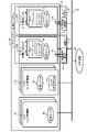
図1に示すコンテナシステム20は、コンテナがクラスタ化された複数のクラスタ(本例では第1クラスタ12A及び第2クラスタ12Bとする)により構成された仮想化システムである。第1クラスタ12Aは、クラスタ管理部14A及び計算資源クラスタ15Aを有して構成されている。第2クラスタ12Bは、クラスタ管理部14B及び計算資源クラスタ15Bを有して構成されている。
The container system 20 shown in FIG. 1 is a virtualization system configured by a plurality of clusters (in this example, a first cluster 12A and a second cluster 12B) in which containers are clustered. The first cluster 12A is composed of a cluster manager 14A and a computational resource cluster 15A. The second cluster 12B is composed of a cluster manager 14B and a computational resource cluster 15B.
クラスタ管理部14A,14Bは、通信振分部14aと、計算資源操作部14bと、計算資源管理部14cと、コンテナ構成受付部14dと、コンテナ配置先決定部14eと、コンテナ管理部14fとを備えて構成されている。計算資源クラスタ15A,15Bは、複数のアプリケーション15a,15bを備えて構成されている。
The cluster management units 14A and 14B include a communication distribution unit 14a, a computational resource operation unit 14b, a computational resource management unit 14c, a container configuration reception unit 14d, a container placement destination determination unit 14e, and a container management unit 14f. configured with. The computational resource clusters 15A, 15B are configured with a plurality of applications 15a, 15b.
なお、クラスタ管理部14A,14Bは、クラスタ管理部14とも称し、計算資源クラスタ15A,15Bは、計算資源クラスタ15とも称す。
The cluster management units 14A and 14B are also called the cluster management unit 14, and the computational resource clusters 15A and 15B are also called the computational resource cluster 15.
図1に示す仮想化システム復旧装置(復旧装置ともいう)10は、コンテナシステム20において障害が発生したコンテナの異常検知と障害復旧を行うものである。この復旧装置10は、クラスタ管理部14A,14Bと、計算資源クラスタ15A,15Bと、内部異常検知部17A,17Bと、異常復旧対応部18A,18Bと、障害対応デプロイ指示部19A,19Bと、振分先切替部21と、外部異常検知部23とを備えて構成されている。
The virtualization system recovery device (also referred to as recovery device) 10 shown in FIG. The recovery device 10 includes cluster management units 14A and 14B, computational resource clusters 15A and 15B, internal anomaly detection units 17A and 17B, anomaly recovery handling units 18A and 18B, failure handling deployment instruction units 19A and 19B, It comprises a distribution destination switching unit 21 and an external abnormality detection unit 23 .
なお、内部異常検知部17A,17Bは、内部異常検知部17とも称し、異常復旧対応部18A,18Bは、異常復旧対応部18とも称し、障害対応デプロイ指示部19A,19Bは、障害対応デプロイ指示部19とも称す。
The internal abnormality detection units 17A and 17B are also referred to as the internal abnormality detection unit 17, the abnormality recovery response units 18A and 18B are also referred to as the abnormality recovery response unit 18, and the failure response deployment instruction units 19A and 19B are failure response deployment instructions. Also referred to as part 19.
各クラスタ12A,12Bの内部には、内部異常検知部17と、異常復旧対応部18と、障害対応デプロイ指示部19とが配備されている。各クラスタ12A,12Bの外部には、振分先切替部21及び外部異常検知部23が配備されている。但し、内部異常検知部17、異常復旧対応部18、障害対応デプロイ指示部19、振分先切替部21及び外部異常検知部23は、コンテナ仮想化ソフトウェアにより仮想的に作成されるクラスタ管理部14及び計算資源クラスタ15の外部に配備されている。また、内部異常検知部17、異常復旧対応部18及び障害対応デプロイ指示部19は、振分先切替部21及び外部異常検知部23と同様に、各クラスタ12A,12Bの外部に配備してもよい。
Inside each cluster 12A, 12B, an internal anomaly detection unit 17, an anomaly recovery handling unit 18, and a failure handling deployment instruction unit 19 are deployed. A distribution destination switching unit 21 and an external abnormality detection unit 23 are provided outside each of the clusters 12A and 12B. However, the internal abnormality detection unit 17, the abnormality recovery response unit 18, the failure response deployment instruction unit 19, the distribution destination switching unit 21, and the external abnormality detection unit 23 are the cluster management unit 14 virtually created by the container virtualization software. and outside the computing resource cluster 15 . Also, the internal anomaly detection unit 17, the anomaly recovery response unit 18, and the failure handling deployment instruction unit 19 can be deployed outside the respective clusters 12A and 12B in the same way as the allocation destination switching unit 21 and the external anomaly detection unit 23. good.
第1及び第2クラスタ12A,12Bは実質上同構成であるため、第1クラスタ12Aを代表して機能構成を説明する。
Since the first and second clusters 12A and 12B have substantially the same configuration, the functional configuration will be described on behalf of the first cluster 12A.
計算資源クラスタ15は、複数のアプリケーション15a,15bを備えて構成されている。アプリケーション15a,15bは、言い換えれば、1又は複数のコンテナの集合体の管理単位としてのPod(図3に示すPod15a,15b参照)である。Podは、クーバネテス(コンテナ仮想化ソフトウェア)で実行できるアプリケーションの最小単位である。つまり、Podとしてのアプリケーション15a,15bでコンテナを作成してクラスタ化し、このクラスタをコンテナエンジン上で作動させるようになっている。この計算資源クラスタ15は、物理マシン上にコンテナ仮想化ソフトウェアにより仮想的に作成され、当該仮想的に作成されるコンテナをクラスタ化して配置するものである。
The computational resource cluster 15 is configured with a plurality of applications 15a and 15b. The applications 15a and 15b are, in other words, Pods (see Pods 15a and 15b shown in FIG. 3) as management units for a collection of one or more containers. A Pod is the smallest unit of an application that can be executed on Kubernetes (container virtualization software). That is, the applications 15a and 15b as pods create containers and cluster them, and the clusters are operated on the container engine. The computing resource cluster 15 is virtually created on a physical machine by container virtualization software, and clusters and arranges the virtually created containers.
クラスタ管理部14は、上記仮想的に作成され、上記クラスタ化されたコンテナの配置及び動作に係る制御を管理するものである。このクラスタ管理部14は、通信振分部14aと、計算資源操作部14bと、計算資源管理部14cと、コンテナ構成受付部14dと、コンテナ配置先決定部14eと、コンテナ管理部14fとを備えて構成されている。
The cluster management unit 14 manages the placement and operation of the virtually created and clustered containers. The cluster management unit 14 includes a communication allocation unit 14a, a computational resource operation unit 14b, a computational resource management unit 14c, a container configuration reception unit 14d, a container arrangement destination determination unit 14e, and a container management unit 14f. configured as follows.
このような構成の復旧装置10において、障害対応デプロイ指示部(デプロイ指示部ともいう)19は、図2に示すエンドポイント(終点)設定部14j,14kとPod15a,15bとを、1:1の構成としてデプロイ(配置)する処理を行う。エンドポイント設定部14j,14kは、複数のPod15a,15b毎に対応付けられ、各Pod15a,15bへのトラフィックの振分割合(%)が設定され、通信データの終点となる。
In the recovery device 10 having such a configuration, the failure handling deployment instruction unit (also referred to as the deployment instruction unit) 19 connects the endpoint (end point) setting units 14j and 14k and the Pods 15a and 15b shown in FIG. Perform the process of deploying (arranging) as a configuration. The endpoint setting units 14j and 14k are associated with each of the plurality of Pods 15a and 15b, set the distribution ratio (%) of traffic to each of the Pods 15a and 15b, and serve as the end point of communication data.
図1に示す内部異常検知部17は、コンテナシステム20内の1又は複数のコンテナであるPod(アプリケーション)15a,15bの異常を検知する。
The internal anomaly detection unit 17 shown in FIG. 1 detects an anomaly in Pods (applications) 15a and 15b, which are one or more containers in the container system 20.
異常復旧対応部18は、内部異常検知部17で異常が検知されたPod(例えばPod15a)に対応付けられたデプロイ指示部19のウエイト値を0%に変更して、異常Pod15aを切り離すための変更コマンドを通信振分部14aへ送信する。また、異常復旧対応部18は、その切り離したPod15aを復旧する場合、復旧対象のPod15aへのトラフィックを予め定められた所定トラフィック値まで徐々に上げるための復旧コマンドを通信振分部14aへ送信する。
The error recovery handling unit 18 changes the weight value of the deployment instruction unit 19 associated with the Pod (for example, Pod 15a) in which an error has been detected by the internal error detection unit 17 to 0%, thereby isolating the error Pod 15a. The command is sent to the communication distribution unit 14a. Further, when restoring the disconnected Pod 15a, the abnormality restoration handling unit 18 transmits a restoration command for gradually increasing the traffic to the Pod 15a to be restored to a predetermined traffic value to the communication distribution unit 14a. .
クラスタ管理部14において、通信振分部14aは、ルータであり、異常復旧対応部18からの変更コマンド又は復旧コマンドを該当する各部14b~14fへ振り分けて通知する。また、通信振分部14aは、後述のエンドポイント設定部14j,14k毎に設定されるトラフィック振分割合を示すウエイト値(%)をもとに、送信先のエンドポイント設定部14j,14k(後述)へのトラフィックの振り分けを行う。
In the cluster management unit 14, the communication distribution unit 14a is a router, and distributes and notifies the change command or recovery command from the failure recovery response unit 18 to the corresponding units 14b to 14f. In addition, the communication distribution unit 14a determines the destination endpoint setting units 14j and 14k ( (described later).
コンテナ構成受付部(受付部ともいう)14dは、計算資源クラスタ15にコンテナをデプロイする構成情報を外部サーバ等から受け取る。
The container configuration reception unit (also referred to as reception unit) 14d receives configuration information for deploying containers to the computational resource cluster 15 from an external server or the like.
コンテナ配置先決定部(配置先決定部ともいう)14eは、受付部14dで受け付けた構成情報をもとに、どのコンテナを、どのワーカーノード(計算資源クラスタ15)に配置するかを決める。
The container placement destination determination unit (also referred to as placement destination determination unit) 14e determines which container to place on which worker node (computation resource cluster 15) based on the configuration information received by the reception unit 14d.
コンテナ管理部14fは、コンテナが正常に動作中か否か等をチェックする。
The container management unit 14f checks whether the container is operating normally.
計算資源管理部14cは、ワーカーノードが動作可能か否か、ワーカーノードを構成するサーバの計算資源の使用量、CPU(Central Processing Unit)残量等を把握して管理する。
The computational resource management unit 14c grasps and manages whether the worker node is operable, the usage amount of computational resources of the server that constitutes the worker node, the remaining amount of CPU (Central Processing Unit), and the like.
計算資源操作部14bは、あるコンテナに対して一定量のCPU等の計算資源を、所定量割り当てる操作、言い換えれば、ストレージ容量の割り当て、CPU時間、コンテナが使用可能なメモリ容量等を割り当てる操作を行う。
The computational resource operation unit 14b performs an operation of allocating a predetermined amount of computational resources such as a certain amount of CPU to a certain container, in other words, an operation of allocating storage capacity, CPU time, memory capacity usable by the container, and the like. conduct.
次に、復旧装置10の内部異常検知部17によるコンテナシステム20のコンテナに係る各種の異常検知処理(第1~第6異常検知処理)について、図3~図8を参照して説明する。
Next, various abnormality detection processes (first to sixth abnormality detection processes) related to the container of the container system 20 by the internal abnormality detection unit 17 of the recovery device 10 will be described with reference to FIGS. 3 to 8. FIG.
<第1異常検知処理>
図3は、本実施形態の仮想化システム復旧装置10のPod(アプリケーション)15a,15bによるコンテナの第1異常検知処理を説明するためのブロック図である。但し、各Pod15a,15bは、1又は複数のコンテナを構成している。 <First abnormality detection process>
FIG. 3 is a block diagram for explaining the first container abnormality detection processing by the Pods (applications) 15a and 15b of the virtualizationsystem restoration device 10 of the present embodiment. However, each Pod 15a, 15b constitutes one or more containers.
図3は、本実施形態の仮想化システム復旧装置10のPod(アプリケーション)15a,15bによるコンテナの第1異常検知処理を説明するためのブロック図である。但し、各Pod15a,15bは、1又は複数のコンテナを構成している。 <First abnormality detection process>
FIG. 3 is a block diagram for explaining the first container abnormality detection processing by the Pods (applications) 15a and 15b of the virtualization
図3において、コンテナシステム20内には、仮想マシンによってマスタノード14Aと、インフラノード14Bと、ワーカーノード15A,15Bとが構成され、各々が仮想スイッチ{OVS(Open vSwitch)}30によって接続されるようになっている。但し、仮想スイッチは、OVS以外に他の仮想スイッチであってもよい。マスタノード14A及びインフラノード14Bは、クラスタ管理部14A,14B(図1)に対応し、ワーカーノード15A,15Bは、計算資源クラスタ15A,15B(図1)に対応している。
In FIG. 3, a master node 14A, an infrastructure node 14B, and worker nodes 15A and 15B are configured by virtual machines in the container system 20, and are connected by a virtual switch {OVS (Open vSwitch)} 30. It's like However, the virtual switch may be a virtual switch other than OVS. The master node 14A and the infrastructure node 14B correspond to the cluster management units 14A and 14B (Fig. 1), and the worker nodes 15A and 15B correspond to the computing resource clusters 15A and 15B (Fig. 1).
更に、マスタノード14A及びワーカーノード15Aで1つ目のクラスタ12が構成され、インフラノード14B及びワーカーノード15Bで2つ目のクラスタ12が構成されている。これらのクラスタ12でコンテナシステム20が構成されているとする。
Further, the master node 14A and the worker node 15A constitute the first cluster 12, and the infrastructure node 14B and the worker node 15B constitute the second cluster 12. Assume that the container system 20 is composed of these clusters 12 .
コンテナシステム20の外部には、図1の構成と同様に内部異常検知部17が配置されている。図3では内部異常検知部17をワーカーノード15A,15B毎に合計2つ記載しているが、1つであってもよい。マスタノード14A、インフラノード14B、ワーカーノード15A,15B、及び内部異常検知部17は、ネットワーク22によって対向装置24に接続されている。対向装置24は、コンテナシステム20に対して要求信号等を送信する外部サーバ等の通信装置である。
An internal abnormality detection unit 17 is arranged outside the container system 20 in the same manner as in the configuration of FIG. Although a total of two internal abnormality detection units 17 are shown for each of the worker nodes 15A and 15B in FIG. 3, the number may be one. The master node 14A, the infrastructure node 14B, the worker nodes 15A and 15B, and the internal anomaly detector 17 are connected to the opposite device 24 via the network 22. FIG. The opposing device 24 is a communication device such as an external server that transmits request signals and the like to the container system 20 .
内部異常検知部17は、往復矢印Y1,Y2で示すポーリングによって、所定のコマンド(例えば「sudo crictl ps」)をワーカーノード15A,15BのPod15a,15bへ送信し、コマンドに応じてPod15a,15bから返信されてくる応答結果により正常か異常かを判断する。このポーリング実試験においては、ポーリングを10回実行した際の往復時間の平均値が0.06秒であった。
The internal anomaly detection unit 17 transmits a predetermined command (for example, "sudo crictl ps") to the Pods 15a and 15b of the worker nodes 15A and 15B by polling indicated by the two-way arrows Y1 and Y2. It determines whether it is normal or abnormal based on the returned response result. In this actual polling test, the average round-trip time was 0.06 seconds when polling was performed 10 times.
内部異常検知部17での異常判断は、ポーリングによってPod15a,15bから返信されてくるコマンド応答結果に記載された正常又は異常を示す文字列を読み取って行う。例えば、文字列の「Running」はコンテナ(Pod15a,15b)の動作が正常であることを示し、「Running」以外の文字列は異常であることを示す。このため、内部異常検知部17は、コマンド応答結果に「Running」が記載の場合はコンテナ(Pod15a,15b)の動作が正常と判断し、「Running」以外の文字列が記載の場合は異常と判断する。
The abnormality determination by the internal abnormality detection unit 17 is performed by reading the character string indicating normality or abnormality described in the command response results returned from the Pods 15a and 15b by polling. For example, the character string "Running" indicates that the operation of the container ( Pods 15a, 15b) is normal, and character strings other than "Running" indicate that it is abnormal. Therefore, the internal abnormality detection unit 17 determines that the operation of the container ( Pods 15a, 15b) is normal when "Running" is described in the command response result, and determines that the operation is abnormal when a character string other than "Running" is described. to decide.
<第2異常検知処理>
次に、図4は、本実施形態の仮想化システム復旧装置10のワーカーノード15A,15B毎に備えられたルーティングテーブル15cによる第2異常検知処理を説明するためのブロック図である。 <Second abnormality detection process>
Next, FIG. 4 is a block diagram for explaining the second abnormality detection processing by the routing table 15c provided for each of the worker nodes 15A and 15B of the virtualization system recovery device 10 of this embodiment.
次に、図4は、本実施形態の仮想化システム復旧装置10のワーカーノード15A,15B毎に備えられたルーティングテーブル15cによる第2異常検知処理を説明するためのブロック図である。 <Second abnormality detection process>
Next, FIG. 4 is a block diagram for explaining the second abnormality detection processing by the routing table 15c provided for each of the
ルーティングテーブル(テーブルともいう)15cは、対向装置24からネットワーク22を介して、ワーカーノード15A,15BのPod15a,15bへ送信されるパケットの送信先のコンテナを、送信先を示す経路情報で管理している。このテーブル15cの送信先管理が正しくないと、適切なコンテナにパケットが届かないこととなる。このため、内部異常検知部17でテーブル15cの送信先管理の正常又は異常を検知するようにした。
The routing table (also referred to as a table) 15c manages destination containers of packets transmitted from the remote device 24 to the Pods 15a and 15b of the worker nodes 15A and 15B via the network 22, using route information indicating the destination. ing. If the destination management of this table 15c is not correct, the packet will not reach the appropriate container. For this reason, the internal abnormality detection unit 17 detects whether the transmission destination management of the table 15c is normal or abnormal.
但し、ルーティングテーブル15cは、「iptables」と「nftables」の一対のテーブルから構成されている。この他、ルーティングテーブル15cは、「iptbles」のみ、又は「nftables」のみで構成されていてもよい。
However, the routing table 15c consists of a pair of tables "iptables" and "nftables". Alternatively, the routing table 15c may consist of only "iptbles" or only "nftables".
内部異常検知部17は、往復矢印Y3,Y4で示すポーリングによって、所定のコマンドをワーカーノード15A,15Bの各テーブル15cへ送信し、コマンドに応じて各テーブル15cから返信されてくる応答結果により正常か異常かを判断する。
The internal abnormality detection unit 17 transmits a predetermined command to each table 15c of the worker nodes 15A and 15B by polling indicated by the two-way arrows Y3 and Y4, and according to the response result returned from each table 15c in response to the command, the normal state is detected. or abnormal.
上記所定のコマンドは、「sudo iptables -L│wc-│」、及び、「sudo nft list ruleset」の一対である。コマンド「sudo iptables -L│wc-│」がテーブル15cの「iptables」に通知され、コマンド「sudo nft list ruleset」が「nftables」に通知される。そして、「iptables」及び「nftables」の各テーブルがコマンドに応じた応答を内部異常検知部17へ返信するようになっている。
The predetermined command above is a pair of "sudo iptables -L|wc-|" and "sudo nft list ruleset". The command "sudo iptables -L|wc-|" is notified to "iptables" of the table 15c, and the command "sudo nft list ruleset" is notified to "nftables". Then, each of the “iptables” and “nftables” tables sends a response to the command to the internal abnormality detection unit 17 .
一対のコマンドによるポーリング実試験においては、ポーリングを10回実行した際の往復時間の平均値が、コマンド「sudo iptables -L│wc-│」の場合に0.03秒であり、コマンド「sudo nft list ruleset」の場合に0.08秒であった。
In actual polling tests using a pair of commands, the average round-trip time when polling was executed 10 times was 0.03 seconds for the command "sudo iptables -L |wc-|", and for the command "sudo nft 0.08 seconds for "list ruleset".
内部異常検知部17での異常判断は、各テーブル15cから返信されてくるコマンド応答結果に、送信先の経路情報が記載されていれば正常と判断し、何も記載されていなければ異常と判断する。
The abnormality determination by the internal abnormality detection unit 17 is determined as normal if the destination route information is described in the command response result returned from each table 15c, and determined as abnormal if nothing is described. do.
<第3異常検知処理>
次に、図5は、本実施形態の仮想化システム復旧装置10のワーカーノード15A,15B毎に備えられた仮想スイッチ30のデーモンの監視による第3異常検知処理を説明するためのブロック図である。なお、仮想スイッチ30のデーモンを、OVSデーモンとも称す。 <Third anomaly detection process>
Next, FIG. 5 is a block diagram for explaining the third abnormality detection processing by monitoring the daemon of thevirtual switch 30 provided for each of the worker nodes 15A and 15B of the virtualization system recovery device 10 of this embodiment. . Note that the daemon of the virtual switch 30 is also called an OVS daemon.
次に、図5は、本実施形態の仮想化システム復旧装置10のワーカーノード15A,15B毎に備えられた仮想スイッチ30のデーモンの監視による第3異常検知処理を説明するためのブロック図である。なお、仮想スイッチ30のデーモンを、OVSデーモンとも称す。 <Third anomaly detection process>
Next, FIG. 5 is a block diagram for explaining the third abnormality detection processing by monitoring the daemon of the
デーモンは、仮想スイッチ30においてパケットの送信先を管理するプログラムである。内部異常検知部17で、OVSデーモンを監視し、パケットが適正に送信されていれば正常、送信されていなければ異常と検知するようにした。
A daemon is a program that manages the destination of packets in the virtual switch 30. The internal anomaly detection unit 17 monitors the OVS daemon, and detects that it is normal if the packet is properly transmitted, and that it is abnormal if it is not transmitted.
内部異常検知部17は、往復矢印Y5,Y6で示すポーリングによって、所定のコマンド(例えば「ps aux|grep ovs-vswitchd|grep "db.sock"|wc-│」)をワーカーノード15A,15B毎の仮想スイッチ30へ送信し、コマンドに応じて仮想スイッチ30から返信されてくる応答結果により正常か異常かを判断する。
The internal abnormality detection unit 17 sends a predetermined command (for example, "ps aux|grep ovs-vswitchd|grep "db.sock"|wc-|") to each of the worker nodes 15A and 15B by polling indicated by the two-way arrows Y5 and Y6. is transmitted to the virtual switch 30, and whether the command is normal or abnormal is determined based on the response result returned from the virtual switch 30 in response to the command.
このポーリング実試験においては、ポーリングを10回実行した際の往復時間の平均値が0.03秒であった。
In this actual polling test, the average round-trip time when polling was performed 10 times was 0.03 seconds.
内部異常検知部17での異常判断は、各仮想スイッチ30から返信されてくるコマンド応答結果に、送信先に係る例えば「db.sockプロセス」が記載されていれば正常と判断し、記載されていなければ異常と判断する。
The abnormality determination by the internal abnormality detection unit 17 is performed by determining that the command response result returned from each virtual switch 30 is normal if, for example, "db.sock process" related to the transmission destination is described. If not, it is judged to be abnormal.
<第4異常検知処理>
次に、図6は、本実施形態の仮想化システム復旧装置10のワーカーノード15A,15B毎に備えられたコンテナランタイム15dのデーモンの監視による第4異常検知処理を説明するためのブロック図である。なお、上記デーモンは、crioデーモンとも称し、コンテナランタイム15dの一例である。crio(cri-o)は、コンテナ型仮想化技術で使われるオープンソースのコミュニティ主導型のコンテナエンジンである。 <Fourth abnormality detection process>
Next, FIG. 6 is a block diagram for explaining the fourth anomaly detection processing by monitoring the daemon of thecontainer runtime 15d provided for each of the worker nodes 15A and 15B of the virtualization system recovery device 10 of this embodiment. . The above daemon is also called a crio daemon, and is an example of the container runtime 15d. crio (cri-o) is an open-source, community-driven container engine used in containerized virtualization technology.
次に、図6は、本実施形態の仮想化システム復旧装置10のワーカーノード15A,15B毎に備えられたコンテナランタイム15dのデーモンの監視による第4異常検知処理を説明するためのブロック図である。なお、上記デーモンは、crioデーモンとも称し、コンテナランタイム15dの一例である。crio(cri-o)は、コンテナ型仮想化技術で使われるオープンソースのコミュニティ主導型のコンテナエンジンである。 <Fourth abnormality detection process>
Next, FIG. 6 is a block diagram for explaining the fourth anomaly detection processing by monitoring the daemon of the
コンテナランタイム15dは、Pod15a,15bのコンテナを起動する役割を担うので、コンテナランタイム15dを監視することでコンテナが正常に起動しているか否かを検知できる。そこで、内部異常検知部17で、crioデーモンを監視し、コンテナが起動していれば正常、起動していなければ異常と検知するようにした。
The container runtime 15d is responsible for starting the containers of the Pods 15a and 15b, so by monitoring the container runtime 15d, it is possible to detect whether the containers are starting normally. Therefore, the internal anomaly detector 17 monitors the crio daemon, and detects that the container is normal if it has started, and that it is abnormal if it has not started.
内部異常検知部17は、往復矢印Y7,Y8で示すポーリングによって、所定のコマンド(例えば「systemctl│status crio|grep Active」)をワーカーノード15A,15B毎のコンテナランタイム15dへ送信し、コマンドに応じて各コンテナランタイム15dから返信されてくる応答結果により正常か異常かを判断する。
The internal abnormality detection unit 17 transmits a predetermined command (for example, "systemctl|status crio|grep Active") to the container runtime 15d of each of the worker nodes 15A and 15B by polling indicated by the two-way arrows Y7 and Y8, and responds to the command. It determines whether it is normal or abnormal based on the response result returned from each container runtime 15d.
このポーリング実試験においては、ポーリングを10回実行した際の往復時間の平均値が0.03秒であった。
In this actual polling test, the average round-trip time when polling was performed 10 times was 0.03 seconds.
内部異常検知部17での異常判断は、各仮想スイッチ30から返信されてくるコマンド応答結果において、crioデーモンの起動状態を示す”active(running)”が記載されていれば正常と判断し、”active(running)”以外の記載であれば異常と判断する。
The abnormality determination by the internal abnormality detection unit 17 is determined as normal if "active (running)" indicating the activation state of the crio daemon is described in the command response result returned from each virtual switch 30, and " Any description other than "active (running)" is judged to be abnormal.
<第5異常検知処理>
次に、図7は、本実施形態の仮想化システム復旧装置10のワーカーノード15A,15B毎の監視による第5異常検知処理を説明するためのブロック図である。 <Fifth anomaly detection process>
Next, FIG. 7 is a block diagram for explaining the fifth anomaly detection processing by monitoring each of the worker nodes 15A and 15B of the virtualization system recovery device 10 of this embodiment.
次に、図7は、本実施形態の仮想化システム復旧装置10のワーカーノード15A,15B毎の監視による第5異常検知処理を説明するためのブロック図である。 <Fifth anomaly detection process>
Next, FIG. 7 is a block diagram for explaining the fifth anomaly detection processing by monitoring each of the
但し、ワーカーノード15A,15Bが、物理マシン32による仮想化技術(仮想マシン)で作成されている構成を前提とする。この構成の場合、仮想マシンの外側の物理マシン32上に内部異常検知部17が存在し、この内部異常検知部17で仮想マシンが起動していればコンテナが正常と検知し、起動していなければコンテナが異常と検知するようにした。
However, it is assumed that the worker nodes 15A and 15B are created by virtualization technology (virtual machines) using physical machines 32. In this configuration, the internal anomaly detector 17 exists on the physical machine 32 outside the virtual machine, and the internal anomaly detector 17 detects that the container is normal if the virtual machine is running. container will detect anomalies.
内部異常検知部17は、往復矢印Y9,Y10で示すポーリングによって、所定のコマンド(例えば「sudo virsh list」)をワーカーノード15A,15B毎へ送信し、コマンドに応じて各ワーカーノード15A,15Bから返信されてくる応答結果により正常か異常かを判断する。
The internal anomaly detection unit 17 transmits a predetermined command (for example, "sudo virsh list") to each of the worker nodes 15A and 15B by polling indicated by the two-way arrows Y9 and Y10. It determines whether it is normal or abnormal based on the returned response result.
このポーリング実試験においては、ポーリングを10回実行した際の往復時間の平均値が0.03秒であった。
In this actual polling test, the average round-trip time when polling was performed 10 times was 0.03 seconds.
内部異常検知部17での異常判断は、各ワーカーノード15A,15Bから返信されてくるコマンド応答結果において、対象のワーカーノード15A,15Bの起動状態を示す”running”が記載されていれば正常と判断し、”running”以外の記載であれば異常と判断する。
The abnormality determination by the internal abnormality detection unit 17 is normal if "running" indicating the activation state of the target worker node 15A, 15B is described in the command response result returned from each worker node 15A, 15B. If the description is anything other than "running", it is determined to be abnormal.
<第6異常検知処理>
次に、図8は、本実施形態の仮想化システム復旧装置10のコンテナシステム20のクラスタ12に外付けされたDB(Data Base)26a,26bの監視による第6異常検知処理を説明するためのブロック図である。 <Sixth anomaly detection process>
Next, FIG. 8 is for explaining the sixth anomaly detection processing by monitoring DBs (Data Bases) 26a and 26b externally attached to the cluster 12 of thecontainer system 20 of the virtualization system recovery device 10 of this embodiment. It is a block diagram.
次に、図8は、本実施形態の仮想化システム復旧装置10のコンテナシステム20のクラスタ12に外付けされたDB(Data Base)26a,26bの監視による第6異常検知処理を説明するためのブロック図である。 <Sixth anomaly detection process>
Next, FIG. 8 is for explaining the sixth anomaly detection processing by monitoring DBs (Data Bases) 26a and 26b externally attached to the cluster 12 of the
各クラスタ12A,12B(図1)の外付けの装置として、コンテナに係るデータを記憶するDB(外部DBともいう)26a,26bを、ネットワーク22を介してワーカーノード15A,15Bに接続する構成がある。この際、内部異常検知部17もネットワーク22を介してワーカーノード15A,15Bに接続されている。
As an external device of each cluster 12A, 12B (FIG. 1), there is a configuration in which DBs (also referred to as external DBs) 26a, 26b that store data related to containers are connected to the worker nodes 15A, 15B via the network 22. be. At this time, the internal abnormality detection unit 17 is also connected to the worker nodes 15A and 15B via the network 22. FIG.
ここで、各クラスタ12A,12Bがネットワーク22を介して相互に接続される構成もあるので、図8に示すように、内部異常検知部17がネットワーク22を介してクラスタ12に接続されていても、図1に示したと同様に、各クラスタ12A,12B内の内部異常検知部17と位置付ける。
Here, since each cluster 12A, 12B may be connected to each other via the network 22, as shown in FIG. , are positioned as the internal abnormality detection units 17 in the respective clusters 12A and 12B in the same manner as shown in FIG.
内部異常検知部17は、往復矢印Y11,Y12で示すポーリングによって、ネットワーク22を介して外部DB26a,26bに所定のコマンドを送信し、コマンドに応じて各外部DB26a,26bから返信されてくる応答結果により正常か異常かを判断する。この場合のコマンドは、外部DB26a,26bの種類に依存したものとなる。
The internal abnormality detection unit 17 transmits predetermined commands to the external DBs 26a and 26b via the network 22 by polling indicated by the two-way arrows Y11 and Y12, and response results returned from the external DBs 26a and 26b in response to the commands. determines whether it is normal or abnormal. The commands in this case depend on the types of the external DBs 26a and 26b.
応答結果としては、応答・死活監視に係る結果と、コネクション数上限オーバーに係る結果とがある。応答・死活監視は、外部DB26a,26bが正常に起動しているか否かを監視するものである。つまり、内部異常検知部17は、応答結果に、外部DB26a,26bが正常に起動していない内容が記載されていれば異常と判断する。
The response results include the results related to responses and life-and-death monitoring, and the results related to exceeding the upper limit on the number of connections. The response/life-and-death monitoring monitors whether the external DBs 26a and 26b are operating normally. In other words, the internal abnormality detection unit 17 determines that there is an abnormality if the response result indicates that the external DBs 26a and 26b have not started normally.
コネクション数上限オーバーは、外部DB26a,26bが接続されているコンテナ数が、予め定められた閾値を超えていることを表す。つまり、内部異常検知部17は、応答結果に、外部DB26a,26bの接続コンテナ数が閾値を超えていることが記載されていれば異常と判断する。
"Exceeding the upper limit of the number of connections" indicates that the number of containers to which the external DBs 26a and 26b are connected exceeds a predetermined threshold. In other words, the internal abnormality detection unit 17 determines that there is an abnormality if the response result indicates that the number of connected containers in the external DBs 26a and 26b exceeds the threshold.
このポーリング実試験においては、ポーリング往復時間は外部DB26a,26bの種類に依存したものとなる。
In this polling actual test, the polling round-trip time depends on the types of the external DBs 26a and 26b.
<複数クラスタ異常検知1>
次に、図9に示す外部異常検知部23によって、複数のクラスタ12A,12Bにおいて障害が発生した場合に、その障害に係る異常検知の処理について説明する。但し、クラスタ12A,12B毎の異常検知1は、上述した第1~第6異常検知の何れか1つであるとする。 <Multi-cluster anomaly detection 1>
Next, when a failure occurs in a plurality of clusters 12A and 12B by the external anomaly detection unit 23 shown in FIG. 9, an anomaly detection process related to the failure will be described. However, it is assumed that the abnormality detection 1 for each of the clusters 12A and 12B is one of the first to sixth abnormality detections described above.
次に、図9に示す外部異常検知部23によって、複数のクラスタ12A,12Bにおいて障害が発生した場合に、その障害に係る異常検知の処理について説明する。但し、クラスタ12A,12B毎の異常検知1は、上述した第1~第6異常検知の何れか1つであるとする。 <Multi-cluster anomaly detection 1>
Next, when a failure occurs in a plurality of
図9に示すように、外部異常検知部23は、第1クラスタ12Aの内部異常検知部17Aと、第2クラスタ12Bの内部異常検知部17Bとに接続されている。外部異常検知部23は、内部異常検知部17A,17Bで上記第1~第6異常検知の何れか1つに係る異常が検知された際に、矢印Y31a又はY31bで示すように、異常のアプリケーション15a,15bに係るコンテナが配置されたクラスタ12A又は12Bを異常と検知する。
As shown in FIG. 9, the external anomaly detector 23 is connected to the internal anomaly detector 17A of the first cluster 12A and the internal anomaly detector 17B of the second cluster 12B. When the internal abnormality detection units 17A and 17B detect an abnormality related to any one of the first to sixth abnormality detections, the external abnormality detection unit 23 detects an abnormality application as indicated by an arrow Y31a or Y31b. The cluster 12A or 12B in which the containers related to 15a and 15b are arranged is detected as abnormal.
<複数クラスタの異常検知2>
図9に示す外部異常検知部23は、第1クラスタ12Aにおけるクラスタ管理部14Aの通信振分部14aと、第2クラスタ12Bにおけるクラスタ管理部14Bの通信振分部14aとに接続されている。通信振分部14aは、クラスタ管理部14の信号入力部分に配備されており、入力信号を後段へ振り分けて出力すると共に、クラスタ12A,12B毎の確認通信に応じて、クラスタ12A,12Bの正常時に応答を返信する。 <Anomaly detection 2 for multiple clusters>
The externalanomaly detection unit 23 shown in FIG. 9 is connected to the communication allocation unit 14a of the cluster management unit 14A in the first cluster 12A and the communication allocation unit 14a of the cluster management unit 14B in the second cluster 12B. The communication distribution unit 14a is arranged in the signal input part of the cluster management unit 14, and distributes the input signal to the subsequent stage and outputs it. Send a response at times.
図9に示す外部異常検知部23は、第1クラスタ12Aにおけるクラスタ管理部14Aの通信振分部14aと、第2クラスタ12Bにおけるクラスタ管理部14Bの通信振分部14aとに接続されている。通信振分部14aは、クラスタ管理部14の信号入力部分に配備されており、入力信号を後段へ振り分けて出力すると共に、クラスタ12A,12B毎の確認通信に応じて、クラスタ12A,12Bの正常時に応答を返信する。 <Anomaly detection 2 for multiple clusters>
The external
外部異常検知部23は、双方向矢印Y33a,Y33bで示すように、クラスタ12A,12B毎の通信振分部14aと一定周期でクラスタ12A,12B毎の確認通信を行い、正常に応答が帰ってくるか否かを検知する。応答が帰ってこない場合に、該当クラスタ12A,12Bの異常と検知する。
As indicated by the two-way arrows Y33a and Y33b, the external abnormality detection unit 23 performs confirmation communication for each cluster 12A and 12B with the communication distribution unit 14a for each cluster 12A and 12B at regular intervals. Detect whether or not it comes. If no response is returned, it is detected that the corresponding clusters 12A and 12B are abnormal.
この複数クラスタの異常検知2では、内部異常検知部17A,17Bを介さず各クラスタ12A,12Bの異常検知が可能となる。
In this multi-cluster anomaly detection 2, anomaly detection of each cluster 12A, 12B is possible without going through the internal anomaly detection units 17A, 17B.
<複数クラスタの異常検知3>
複数クラスタの異常検知3は、外部異常検知部23が、上記異常検知1,2の双方によって、各クラスタ12A,12Bの異常検知を行う処理である。この処理では、各クラスタ12A,12Bの異常検知を、より適正に行うことができる。 <Anomaly detection for multiple clusters 3>
Anomaly detection 3 for a plurality of clusters is a process in which the externalanomaly detection unit 23 performs anomaly detection for each of the clusters 12A and 12B based on both of the anomaly detections 1 and 2 described above. In this process, abnormality detection of each cluster 12A, 12B can be performed more appropriately.
複数クラスタの異常検知3は、外部異常検知部23が、上記異常検知1,2の双方によって、各クラスタ12A,12Bの異常検知を行う処理である。この処理では、各クラスタ12A,12Bの異常検知を、より適正に行うことができる。 <Anomaly detection for multiple clusters 3>
Anomaly detection 3 for a plurality of clusters is a process in which the external
図10は、本実施形態の仮想化システム復旧装置10の異常対応処理を説明するためのブロック図である。異常対応処理を行う異常検知は、上記複数クラスタの異常検知1~3の何れか1つである。
FIG. 10 is a block diagram for explaining the anomaly handling processing of the virtualization system recovery device 10 of this embodiment. The abnormality detection for which the abnormality handling process is performed is any one of the abnormality detections 1 to 3 of the plurality of clusters.
振分先切替部21は、復旧装置10の外部のDNS(Domain Name System)25に接続されている。DNS25は、各クラスタ12A,12Bのアプリケーション15a,15bの名称を示すドメイン(又はドメイン名)と、各クラスタ12A,12Bの通信振分部14aの住所に該当する解決先IP(Internet Protocol)アドレスとを対応付けて管理するサーバである。このDNS25は、ドメインとIPアドレスとを相互に変換するものであり、DNSレコードテーブル25aを備えている。
The distribution destination switching unit 21 is connected to a DNS (Domain Name System) 25 outside the recovery device 10 . The DNS 25 contains domains (or domain names) indicating the names of the applications 15a and 15b of the respective clusters 12A and 12B, and resolution destination IP (Internet Protocol) addresses corresponding to the addresses of the communication distribution units 14a of the respective clusters 12A and 12B. is a server that associates and manages The DNS 25 converts between domains and IP addresses, and includes a DNS record table 25a.
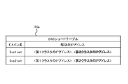
図11に示すように、DNSレコードテーブル(テーブルともいう)25aは、ドメイン名と解決先IPアドレスとを対応付けて記憶している。本例では、テーブル25aにおいて、クラスタ12A,12B毎のアプリケーション15aのドメイン名としての「Svc1.net」に、クラスタ12A,12B毎の通信振分部14aの解決先IPアドレスとしての「第1クラスタ12AのIPアドレス」及び「第2クラスタ12BのIPアドレス」が対応付けられている。
As shown in FIG. 11, the DNS record table (also referred to as table) 25a stores domain names and resolution destination IP addresses in association with each other. In this example, in the table 25a, "Svc1.net" as the domain name of the application 15a for each of the clusters 12A and 12B is added to "first cluster 12A' and 'the IP address of the second cluster 12B' are associated with each other.
この対応付け関係は、「Svc1.net」のアプリケーション15aが、第1クラスタ12A又は第2クラスタ12Bで作動することを表している。
This correspondence relationship indicates that the "Svc1.net" application 15a operates in the first cluster 12A or the second cluster 12B.
更に、テーブル25aにおいて、クラスタ12A,12B毎のアプリケーション15bのドメイン名としての「Svc2.net」に、クラスタ12A,12B毎の通信振分部14aの解決先IPアドレスとしての「第1クラスタ12AのIPアドレス」及び「第2クラスタ12BのIPアドレス」が対応付けられている。
Furthermore, in the table 25a, "Svc2.net" as the domain name of the application 15b for each of the clusters 12A and 12B is added to "Svc2.net" as the resolution destination IP address of the communication distribution unit 14a for each of the clusters 12A and 12B. "IP address" and "IP address of the second cluster 12B" are associated with each other.
この対応付け関係は、「Svc2.net」のアプリケーション15bが、第1クラスタ12A又は第2クラスタ12Bで作動することを表している。
This correspondence relationship indicates that the "Svc2.net" application 15b operates in the first cluster 12A or the second cluster 12B.
このようなテーブル25aを備えるDNS25に、外部サーバ(図示せず)が解決先IPアドレスを問い合わせると、DNS25から、各クラスタ12A,12Bの双方のIPアドレスが返信されてくる。このため、外部サーバは、各クラスタ12A,12Bの何れにもデータ送信が可能となる。
When an external server (not shown) queries the DNS 25 having such a table 25a for the resolution destination IP address, the DNS 25 returns the IP addresses of both clusters 12A and 12B. Therefore, the external server can transmit data to both clusters 12A and 12B.
ここで、図10に示す外部異常検知部23において、複数クラスタ12A,12Bの異常検知1~3の何れか1つの異常(例えば第2クラスタ12Bの異常)が検知されたとする。外部異常検知部23は、その第2クラスタ12Bの異常検知を矢印Y34で示すように、振分先切替部21へ通知する。
Here, it is assumed that the external anomaly detection unit 23 shown in FIG. 10 detects an anomaly in any one of the anomaly detections 1 to 3 of the plurality of clusters 12A and 12B (for example, an anomaly of the second cluster 12B). The external anomaly detection unit 23 notifies the allocation destination switching unit 21 of the anomaly detection of the second cluster 12B as indicated by an arrow Y34.
振分先切替部21は、第2クラスタ12Bへの通信振り分けを中止する指示(通信振分中止指示)を、矢印Y35で示すようにDNS25へ通知する。DNS25は、通信振分中止指示に応じて、図12に示すテーブル25aにおけるドメイン名の「Svc1.net」及び「Svc2.net」の双方に対応付けられた解決先IPアドレスにおいて、第2クラスタ12BのIPアドレスを消去する処理を行う。
The distribution destination switching unit 21 notifies the DNS 25 of an instruction to stop the communication distribution to the second cluster 12B (communication distribution stop instruction) as indicated by an arrow Y35. In response to the communication distribution stop instruction, the DNS 25 resolves the second cluster 12B to the resolution destination IP address associated with both the domain names "Svc1.net" and "Svc2.net" in the table 25a shown in FIG. process to delete the IP address of
<実施形態の動作>
次に、異常対応処理の動作を、図13に示すフローチャートを参照して説明する。 <Operation of Embodiment>
Next, the operation of the abnormality handling process will be described with reference to the flowchart shown in FIG.
次に、異常対応処理の動作を、図13に示すフローチャートを参照して説明する。 <Operation of Embodiment>
Next, the operation of the abnormality handling process will be described with reference to the flowchart shown in FIG.
図13に示すステップS1において、第2クラスタ12Bのアプリケーション15a,15bに障害(×印)が発生し、この異常が内部異常検知部17Bで検知されたとする。この場合、内部異常検知部17Bで第2クラスタ12Bの異常が矢印Y31bに示すように、外部異常検知部23へ通知される。
Assume that in step S1 shown in FIG. 13, a failure (x mark) occurs in the applications 15a and 15b of the second cluster 12B, and this abnormality is detected by the internal abnormality detection unit 17B. In this case, the internal abnormality detection section 17B notifies the external abnormality detection section 23 of the abnormality of the second cluster 12B as indicated by an arrow Y31b.
ステップS2において、外部異常検知部23は、上記通知によって第2クラスタ12Bの異常を検知し、矢印Y34で示すように、振分先切替部21へ通知する。
In step S2, the external anomaly detection unit 23 detects an anomaly in the second cluster 12B from the above notification, and notifies the allocation destination switching unit 21 as indicated by an arrow Y34.
ステップS3において、振分先切替部21は、第2クラスタ12Bへの通信振分中止指示を、矢印Y35で示すようにDNS25へ通知する。
In step S3, the distribution destination switching unit 21 notifies the DNS 25 of an instruction to stop communication distribution to the second cluster 12B, as indicated by an arrow Y35.
ステップS4において、DNS25は、図12に示すテーブル25aにおけるドメイン名の「Svc1.net」及び「Svc2.net」の双方に対応付けられた解決先IPアドレスにおいて、第2クラスタ12BのIPアドレスを消去する。これによって、テーブル25aのドメイン名の「Svc1.net」及び「Svc2.net」の双方に対応付けられた解決先IPアドレスは、第1クラスタ12AのIPアドレスのみとなる。
In step S4, the DNS 25 deletes the IP address of the second cluster 12B from the resolution destination IP addresses associated with both the domain names "Svc1.net" and "Svc2.net" in the table 25a shown in FIG. do. As a result, the resolution destination IP address associated with both of the domain names "Svc1.net" and "Svc2.net" in the table 25a is only the IP address of the first cluster 12A.
このため、ステップS5において、外部サーバがDNS25に解決先IPアドレスを問い合わせた場合に、DNS25からは第1クラスタ12AのIPアドレスのみが返信される。言い換えれば、障害が発生した第2クラスタ12Bへはアクセス出来なくなるので、第2クラスタ12Bへの通信が止められることになる。
Therefore, in step S5, when the external server inquires of the DNS 25 about the resolution destination IP address, the DNS 25 returns only the IP address of the first cluster 12A. In other words, access to the failed second cluster 12B becomes impossible, and communication to the second cluster 12B is stopped.
<実施形態の効果>
本発明の実施形態に係る仮想化システム復旧装置10の効果について説明する。 <Effects of Embodiment>
Effects of the virtualizationsystem recovery device 10 according to the embodiment of the present invention will be described.
本発明の実施形態に係る仮想化システム復旧装置10の効果について説明する。 <Effects of Embodiment>
Effects of the virtualization
(1a)復旧装置10は、計算資源クラスタ15と、クラスタ管理部14と、複数のクラスタ12A,12Bと、内部異常検知部17と、外部異常検知部23とを備える。計算資源クラスタ15は、物理マシン上にコンテナ仮想化ソフトウェアにより仮想的に作成され、当該仮想的に作成されるコンテナをクラスタ化して配置する。クラスタ管理部14は、仮想的に作成され、クラスタ化されたコンテナの配置及び動作に係る制御を管理する。
(1a) The restoration device 10 includes a computational resource cluster 15, a cluster management unit 14, a plurality of clusters 12A and 12B, an internal anomaly detection unit 17, and an external anomaly detection unit 23. The computational resource cluster 15 is virtually created on a physical machine by container virtualization software, and clusters and arranges the virtually created containers. The cluster management unit 14 manages the placement and operation of virtually created and clustered containers.
各クラスタ12A,12Bは、計算資源クラスタ15及びクラスタ管理部14を有して構成される。内部異常検知部17は、クラスタ12A,12B毎に配置され、且つ仮想的に作成された計算資源クラスタ15及びクラスタ管理部14の外部に仮想的に作成され、コンテナの異常を検知する。外部異常検知部23は、各クラスタ12A,12Bの外部に仮想的に作成され、内部異常検知部17でのコンテナの異常検知時に当該異常のコンテナが配置されたクラスタを異常と検知する構成とした。
Each cluster 12A, 12B is configured with a computational resource cluster 15 and a cluster management unit 14. The internal anomaly detector 17 is arranged for each of the clusters 12A and 12B and is virtually created outside the virtually created computational resource cluster 15 and the cluster manager 14 to detect an anomaly of the container. The external anomaly detector 23 is virtually created outside each of the clusters 12A and 12B, and configured to detect an anomaly in the cluster in which the abnormal container is arranged when the internal anomaly detector 17 detects an anomaly in the container. .
この構成によれば、クラスタ12A,12B毎の内部異常検知部17でコンテナの異常が検知された際に、外部異常検知部23で、その異常のコンテナが配置されたクラスタを異常と検知するようにした。内部異常検知部17及び外部異常検知部23は、クラスタ管理部14及び計算資源クラスタ15を仮想的に作成するコンテナ仮想化ソフトウェアに関与しない。このため、各クラスタ12A,12Bで発生した障害をコンテナ仮想化ソフトウェアが持つ異常検知復旧機能よりも、早く異常検知できる。この早い異常検知によってクラスタの障害に係るコンテナ等を早く復旧できる。
According to this configuration, when the internal abnormality detection unit 17 of each of the clusters 12A and 12B detects an abnormality in the container, the external abnormality detection unit 23 detects that the cluster in which the abnormal container is arranged is abnormal. made it The internal anomaly detector 17 and the external anomaly detector 23 are not involved in container virtualization software that virtually creates the cluster manager 14 and the computational resource cluster 15 . Therefore, failures occurring in the respective clusters 12A and 12B can be detected earlier than the abnormality detection recovery function of the container virtualization software. This early detection of anomalies enables quick recovery of containers and the like related to cluster failures.
(2a)クラスタ管理部14は、当該クラスタ管理部14の信号入力部分に配備され、入力信号を後段へ振り分けて出力すると共に、クラスタの確認通信に応じて当該クラスタの正常時に応答を返信する通信振分部14aを備える。外部異常検知部23は、通信振分部14aに所定周期でクラスタの確認通信を行い、応答が返信されない場合にクラスタの異常と検知する構成とした。
(2a) The cluster management unit 14 is arranged in the signal input part of the cluster management unit 14, distributes the input signal to the subsequent stage and outputs it, and communicates to return a response when the cluster is normal according to the confirmation communication of the cluster. A distribution unit 14a is provided. The external anomaly detection unit 23 is configured to perform cluster confirmation communication to the communication distribution unit 14a at predetermined intervals, and to detect an anomaly in the cluster when no response is returned.
この構成によれば、クラスタ12A,12B毎の内部異常検知部17を介さず各クラスタの異常を検知できる。
According to this configuration, the abnormality of each cluster can be detected without going through the internal abnormality detection unit 17 of each cluster 12A, 12B.
(3a)外部異常検知部23は、内部異常検知部17でのコンテナの異常検知時に当該コンテナが配置されたクラスタを異常と検知する処理と、通信振分部14aに所定周期でクラスタの確認通信を行い、応答が返信されない場合にクラスタの異常と検知する処理との双方の処理によって異常を検知する構成とした。
(3a) The external anomaly detection unit 23 detects an anomaly in the cluster in which the container is placed when the internal anomaly detection unit 17 detects an anomaly in the container. , and when no response is returned, the abnormality is detected by both the process of detecting the abnormality of the cluster and the process of detecting it.
この構成によれば、各クラスタの異常検知を、より適正に行うことができる。
According to this configuration, anomaly detection of each cluster can be performed more appropriately.
(4a)コンテナに係るアプリケーションの名称を示すドメイン名と、クラスタ毎のIPアドレスとを対応付けて管理するDNS25を、各クラスタ12A,12Bを構成するサーバの外部に備える。各クラスタ12A,12Bの外部に仮想的に作成され、外部異常検知部23で検知された異常のクラスタに係る通信振分中止指示をDNS25へ通知する振分先切替部を、クラスタ毎に備える。DNS25は、通信振分中止指示で示される異常のクラスタのIPアドレスを消去する構成とした。
(4a) The DNS 25 that manages the domain name indicating the name of the application related to the container in association with the IP address of each cluster is provided outside the servers that constitute each cluster 12A and 12B. A distribution destination switching unit, which is virtually created outside each cluster 12A, 12B and notifies the DNS 25 of a communication distribution stop instruction related to an abnormal cluster detected by the external abnormality detection unit 23, is provided for each cluster. The DNS 25 is configured to delete the IP address of the abnormal cluster indicated by the communication distribution stop instruction.
この構成によれば、DNS25で管理されるクラスタのIPアドレスにおいて、外部異常検知部23で異常検知されたクラスタのIPアドレスが消去される。このため、外部サーバがDNS25にクラスタのIPアドレスを問い合わせた場合に、障害が発生したクラスタのIPアドレスにはアクセス出来なくなる。つまり、異常のクラスタへの通信を止めることができる。外部異常検知部23、振分先切替部及びDNS25は、上述したコンテナ仮想化ソフトウェアに関与しない。このため、クラスタで発生した障害をコンテナ仮想化ソフトウェアが持つ異常検知復旧機能よりも、早く異常検知できるので、この異常検知されたクラスタの障害に係るコンテナ等を早く復旧できる。
According to this configuration, the IP address of the cluster detected as abnormal by the external abnormality detection unit 23 is deleted from the cluster IP addresses managed by the DNS 25 . Therefore, when the external server queries the DNS 25 for the IP address of the cluster, it cannot access the IP address of the failed cluster. In other words, communication to the abnormal cluster can be stopped. The external abnormality detection unit 23, the allocation destination switching unit, and the DNS 25 are not involved in the container virtualization software described above. For this reason, a failure occurring in a cluster can be detected earlier than the failure detection and recovery function of the container virtualization software, so that the container or the like related to the failure of the cluster in which the failure has been detected can be quickly restored.
<実施形態の変形例1>
図14は、本発明の実施形態の変形例1に係る仮想化システム復旧装置10Aの構成を示すブロック図である。 <Modification 1 of Embodiment>
FIG. 14 is a block diagram showing the configuration of a virtualizationsystem restoration device 10A according to Modification 1 of the embodiment of the present invention.
図14は、本発明の実施形態の変形例1に係る仮想化システム復旧装置10Aの構成を示すブロック図である。 <Modification 1 of Embodiment>
FIG. 14 is a block diagram showing the configuration of a virtualization
図14に示す変形例1の復旧装置10Aが、復旧装置10(図10)と異なる点は、振分先切替部21からの矢印Y35で示す通信振分中止指示を、DNS25の他に、各クラスタ12A,12Bの通信振分部14aへも通知するようにしたことにある。
14 differs from the recovery device 10 (FIG. 10) in that the communication distribution stop instruction indicated by the arrow Y35 from the distribution destination switching unit 21 is The reason for this is that the notification is also sent to the communication distribution units 14a of the clusters 12A and 12B.
通信振分部14aは、その通知された通信振分中止指示で示される第1クラスタ12A又は第2クラスタ12Bの通信を停止する。つまり、各クラスタ12A,12Bへの通信は、必ず入力側の通信振分部14aを経由して行われるので、その通信振分部14aの通信機能を通信振分中止指示に応じて停止するようにした。
The communication distribution unit 14a stops the communication of the first cluster 12A or the second cluster 12B indicated by the notified communication distribution stop instruction. That is, since communication to each cluster 12A, 12B is always performed via the communication distribution unit 14a on the input side, the communication function of the communication distribution unit 14a is stopped in response to the communication distribution stop instruction. made it
この構成によれば、異常のクラスタ(例えば第2クラスタ12B)に係る通信振分中止指示を、異常クラスタ12Bの通信振分部14aへ通知して、通信振分部14aの通信機能を停止できる。この停止によって、異常クラスタ12Bへはアクセス出来なくなる。このため、外部サーバのDNS25への問い合わせを省略できる。
According to this configuration, the communication distribution stop instruction for the abnormal cluster (for example, the second cluster 12B) can be sent to the communication distribution unit 14a of the abnormal cluster 12B, and the communication function of the communication distribution unit 14a can be stopped. . This stop makes it impossible to access the abnormal cluster 12B. Therefore, it is possible to omit the inquiry to the DNS 25 of the external server.
<実施形態の変形例2>
図15は、本実施形態の変形例2に係る仮想化システム復旧装置10Bの構成を示すブロック図である。 <Modification 2 of Embodiment>
FIG. 15 is a block diagram showing the configuration of a virtualizationsystem recovery device 10B according to Modification 2 of this embodiment.
図15は、本実施形態の変形例2に係る仮想化システム復旧装置10Bの構成を示すブロック図である。 <Modification 2 of Embodiment>
FIG. 15 is a block diagram showing the configuration of a virtualization
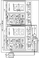
図15に示す変形例2の復旧装置10Bが、復旧装置10(図10)と異なる点は、第1クラスタ12Aに内部DNS25Aを備えると共に、第2クラスタ12Bに内部DNS25Bを備え、振分先切替部21からの矢印Y35で示す通信振分中止指示を、DNS25の他に、各内部DNS25A,25Bへも通知するようにしたことにある。
15 differs from the recovery device 10 (FIG. 10) in that the first cluster 12A is equipped with an internal DNS 25A, the second cluster 12B is equipped with an internal DNS 25B, and the distribution destination switching is performed. In addition to the DNS 25, the internal DNS 25A and 25B are also notified of the communication distribution stop instruction indicated by the arrow Y35 from the unit 21. FIG.
内部DNS25A,25Bは、DNS25と同様にDNSレコードテーブル25aを備えるが、異なる点は、テーブル25aをキャッシュメモリに備えている。従って、内部DNS25A,25Bでは、テーブル25aの情報が所定時間で消去される。しかし、内部DNS25A,25Bは、その消去後に、必要に応じてDNS25から必要情報を取得可能となっている。
The internal DNS 25A, 25B have a DNS record table 25a like the DNS 25, but the difference is that the table 25a is provided in cache memory. Therefore, in the internal DNS 25A, 25B, the information in the table 25a is deleted after a predetermined period of time. However, the internal DNS 25A, 25B can acquire necessary information from the DNS 25 as needed after the erasure.
内部異常検知部17A(又は内部異常検知部17B)は、第2クラスタ12Bの異常が検知された際の通信振分中止指示(矢印Y35参照)に応じて、図12に示すテーブル25aの第2クラスタ12BのIPアドレスを消去する処理を行う。
The internal anomaly detection unit 17A (or the internal anomaly detection unit 17B) responds to the communication distribution stop instruction (see arrow Y35) when the anomaly of the second cluster 12B is detected. A process of deleting the IP address of the cluster 12B is performed.
この構成によれば、外部サーバが、クラスタ毎の内部DNS25A,25Bに各クラスタ12A,12BのIPアドレスの問い合わせを行うことができるので、外部のDNS25への負荷を減少できる。
According to this configuration, the external server can query the internal DNS 25A, 25B of each cluster for the IP address of each cluster 12A, 12B, so the load on the external DNS 25 can be reduced.
<ハードウェア構成>
上述した実施形態に係る仮想化システム復旧装置10,10A,10Bの何れか1つは、例えば図16に示すような構成のコンピュータ100によって実現される。コンピュータ100は、CPU(Central Processing Unit)101、ROM(Read Only Memory)102、RAM(Random Access Memory)103、HDD(Hard Disk Drive)104、入出力I/F(Interface)105、通信I/F106、及びメディアI/F107を有する。 <Hardware configuration>
Any one of the virtualization system recovery apparatuses 10, 10A, and 10B according to the above-described embodiments is implemented by a computer 100 configured as shown in FIG. 16, for example. The computer 100 includes a CPU (Central Processing Unit) 101, a ROM (Read Only Memory) 102, a RAM (Random Access Memory) 103, a HDD (Hard Disk Drive) 104, an input/output I/F (Interface) 105, and a communication I/F 106. , and a media I/F 107 .
上述した実施形態に係る仮想化システム復旧装置10,10A,10Bの何れか1つは、例えば図16に示すような構成のコンピュータ100によって実現される。コンピュータ100は、CPU(Central Processing Unit)101、ROM(Read Only Memory)102、RAM(Random Access Memory)103、HDD(Hard Disk Drive)104、入出力I/F(Interface)105、通信I/F106、及びメディアI/F107を有する。 <Hardware configuration>
Any one of the virtualization
CPU101は、ROM102又はHDD104に記憶されたプログラムに基づき作動し、各機能部の制御を行う。ROM102は、コンピュータ100の起動時にCPU101により実行されるブートプログラムや、コンピュータ100のハードウェアに係るプログラム等を記憶する。
The CPU 101 operates based on programs stored in the ROM 102 or HDD 104, and controls each functional unit. The ROM 102 stores a boot program executed by the CPU 101 when the computer 100 is started, a program related to the hardware of the computer 100, and the like.
CPU101は、入出力I/F105を介して、プリンタやディスプレイ等の出力装置111及び、マウスやキーボード等の入力装置110を制御する。CPU101は、入出力I/F105を介して、入力装置110からデータを取得し、又は、生成したデータを出力装置111へ出力する。
The CPU 101 controls an output device 111 such as a printer or display and an input device 110 such as a mouse or keyboard via the input/output I/F 105 . The CPU 101 acquires data from the input device 110 or outputs generated data to the output device 111 via the input/output I/F 105 .
HDD104は、CPU101により実行されるプログラム及び当該プログラムによって使用されるデータ等を記憶する。通信I/F106は、通信網112を介して図示せぬ他の装置からデータを受信してCPU101へ出力し、また、CPU101が生成したデータを、通信網112を介して他の装置へ送信する。
The HDD 104 stores programs executed by the CPU 101 and data used by the programs. Communication I/F 106 receives data from another device (not shown) via communication network 112 and outputs the data to CPU 101, and also transmits data generated by CPU 101 to another device via communication network 112. .
メディアI/F107は、記録媒体113に格納されたプログラム又はデータを読み取り、RAM103を介してCPU101へ出力する。CPU101は、目的の処理に係るプログラムを、メディアI/F107を介して記録媒体113からRAM103上にロードし、ロードしたプログラムを実行する。記録媒体113は、DVD(Digital Versatile Disc)、PD(Phase change rewritable Disk)等の光学記録媒体、MO(Magneto Optical disk)等の光磁気記録媒体、磁気記録媒体、導体メモリテープ媒体又は半導体メモリ等である。
The media I/F 107 reads programs or data stored in the recording medium 113 and outputs them to the CPU 101 via the RAM 103 . The CPU 101 loads a program related to target processing from the recording medium 113 onto the RAM 103 via the media I/F 107, and executes the loaded program. The recording medium 113 is an optical recording medium such as a DVD (Digital Versatile Disc) or a PD (Phase change rewritable Disk), a magneto-optical recording medium such as an MO (Magneto Optical disk), a magnetic recording medium, a conductor memory tape medium, a semiconductor memory, or the like. is.
例えば、コンピュータ100が実施形態に係る仮想化システム復旧装置10,10A,10Bの何れか1つとして機能する場合、コンピュータ100のCPU101は、RAM103上にロードされたプログラムを実行することにより、仮想化システム復旧装置10の機能を実現する。また、HDD104には、RAM103内のデータが記憶される。CPU101は、目的の処理に係るプログラムを記録媒体113から読み取って実行する。この他、CPU101は、他の装置から通信網112を介して目的の処理に係るプログラムを読み込んでもよい。
<効果>
(1)物理マシン上にコンテナ仮想化ソフトウェアにより仮想的に作成され、当該仮想的に作成されるコンテナをクラスタ化して配置する計算資源クラスタと、前記仮想的に作成され、前記クラスタ化されたコンテナの配置及び動作に係る制御を管理するクラスタ管理部と、各々が、前記計算資源クラスタ及び前記クラスタ管理部を有して構成される複数のクラスタと、前記複数のクラスタ毎に配置され、且つ前記仮想的に作成された計算資源クラスタ及びクラスタ管理部の外部に前記仮想的に作成され、前記コンテナの異常を検知する内部異常検知部と、前記複数のクラスタの外部に前記仮想的に作成され、前記内部異常検知部でのコンテナの異常検知時に当該異常のコンテナが配置されたクラスタを異常と検知する外部異常検知部とを備えることを特徴とする仮想化システム復旧装置である。 For example, when thecomputer 100 functions as one of the virtualization system recovery apparatuses 10, 10A, and 10B according to the embodiment, the CPU 101 of the computer 100 executes a program loaded on the RAM 103 to perform virtualization. The function of the system recovery device 10 is realized. Data in the RAM 103 is also stored in the HDD 104 . The CPU 101 reads a program related to target processing from the recording medium 113 and executes it. In addition, the CPU 101 may read a program related to target processing from another device via the communication network 112 .
<effect>
(1) A computational resource cluster that is virtually created on a physical machine by container virtualization software and that clusters and arranges the virtually created containers, and the virtually created and clustered containers a plurality of clusters each configured to include the computing resource cluster and the cluster management unit; arranged for each of the plurality of clusters, and the an internal anomaly detection unit that is virtually created outside the virtually created computational resource cluster and the cluster management unit and detects an anomaly in the container; and the virtually created outside of the plurality of clusters, The virtualization system recovery device is characterized by comprising an external anomaly detection unit that detects an anomaly in a cluster in which the abnormal container is arranged when the internal anomaly detection unit detects an anomaly in the container.
<効果>
(1)物理マシン上にコンテナ仮想化ソフトウェアにより仮想的に作成され、当該仮想的に作成されるコンテナをクラスタ化して配置する計算資源クラスタと、前記仮想的に作成され、前記クラスタ化されたコンテナの配置及び動作に係る制御を管理するクラスタ管理部と、各々が、前記計算資源クラスタ及び前記クラスタ管理部を有して構成される複数のクラスタと、前記複数のクラスタ毎に配置され、且つ前記仮想的に作成された計算資源クラスタ及びクラスタ管理部の外部に前記仮想的に作成され、前記コンテナの異常を検知する内部異常検知部と、前記複数のクラスタの外部に前記仮想的に作成され、前記内部異常検知部でのコンテナの異常検知時に当該異常のコンテナが配置されたクラスタを異常と検知する外部異常検知部とを備えることを特徴とする仮想化システム復旧装置である。 For example, when the
<effect>
(1) A computational resource cluster that is virtually created on a physical machine by container virtualization software and that clusters and arranges the virtually created containers, and the virtually created and clustered containers a plurality of clusters each configured to include the computing resource cluster and the cluster management unit; arranged for each of the plurality of clusters, and the an internal anomaly detection unit that is virtually created outside the virtually created computational resource cluster and the cluster management unit and detects an anomaly in the container; and the virtually created outside of the plurality of clusters, The virtualization system recovery device is characterized by comprising an external anomaly detection unit that detects an anomaly in a cluster in which the abnormal container is arranged when the internal anomaly detection unit detects an anomaly in the container.
この構成によれば、複数のクラスタ毎の内部異常検知部でコンテナの異常が検知された際に、外部異常検知部で、その異常のコンテナが配置されたクラスタを異常と検知するようにした。内部異常検知部及び外部異常検知部は、クラスタ管理部及び計算資源クラスタを仮想的に作成するコンテナ仮想化ソフトウェアに関与しない。このため、複数のクラスタで発生した障害をコンテナ仮想化ソフトウェアが持つ異常検知復旧機能よりも、早く異常検知できる。この早い異常検知によってクラスタの障害に係るコンテナ等を早く復旧できる。
According to this configuration, when an internal anomaly detection unit for each cluster detects an anomaly in a container, the external anomaly detection unit detects an anomaly in the cluster in which the abnormal container is located. The internal anomaly detector and the external anomaly detector do not participate in the container virtualization software that virtually creates the cluster manager and computational resource cluster. Therefore, failures that occur in multiple clusters can be detected more quickly than the failure detection and recovery function of container virtualization software. This early detection of anomalies enables quick recovery of containers and the like related to cluster failures.
(2)前記クラスタ管理部は、当該クラスタ管理部の信号入力部分に配備され、入力信号を後段へ振り分けて出力すると共に、前記クラスタの確認通信に応じて当該クラスタの正常時に応答を返信する通信振分部を備え、前記外部異常検知部は、前記通信振分部に所定周期でクラスタの確認通信を行い、前記応答が返信されない場合に前記クラスタの異常と検知することを特徴とする上記(1)に記載の仮想化システム復旧装置である。
(2) The cluster management unit is arranged in the signal input part of the cluster management unit, distributes the input signal to the subsequent stage and outputs it, and communicates to return a response when the cluster is normal according to the confirmation communication of the cluster. The above ( 1) is the virtualization system recovery device according to the above.
この構成によれば、複数のクラスタ毎の内部異常検知部を介さず各クラスタの異常を検知できる。
According to this configuration, an abnormality in each cluster can be detected without going through the internal abnormality detection units for each of the clusters.
(3)前記外部異常検知部は、前記内部異常検知部でのコンテナの異常検知時に当該コンテナが配置されたクラスタを異常と検知する処理と、前記通信振分部に所定周期でクラスタの確認通信を行い、前記応答が返信されない場合に前記クラスタの異常と検知する処理との双方の処理によって異常を検知することを特徴とする上記(2)に記載の仮想化システム復旧装置である。
(3) The external anomaly detection unit performs processing for detecting an anomaly in the cluster in which the container is placed when the internal anomaly detection unit detects an anomaly in the container, and performs cluster confirmation communication to the communication distribution unit at a predetermined cycle. and, if the response is not returned, the abnormality is detected by both the process of detecting the abnormality of the cluster.
この構成によれば、各クラスタの異常検知を、より適正に行うことができる。
According to this configuration, anomaly detection of each cluster can be performed more appropriately.
(4)前記コンテナに係るアプリケーションの名称を示すドメイン名と、前記クラスタ毎のIP(Internet Protocol)アドレスとを対応付けて管理するDNS(Domain Name System)を、当該クラスタを構成するサーバの外部に備え、前記複数のクラスタの外部に前記仮想的に作成され、前記外部異常検知部で検知された異常のクラスタに係る通信振分中止指示を前記DNSへ通知する振分先切替部を、前記クラスタ毎に備え、前記DNSは、前記通信振分中止指示で示される異常のクラスタのIPアドレスを消去することを特徴とする上記(1)~(3)の何れか1項に記載の仮想化システム復旧装置である。
(4) A DNS (Domain Name System) that manages the domain name indicating the name of the application related to the container in association with the IP (Internet Protocol) address for each cluster is provided outside the server that constitutes the cluster. a distribution destination switching unit that is virtually created outside the plurality of clusters and notifies the DNS of a communication distribution stop instruction related to the abnormal cluster detected by the external abnormality detection unit; The virtualization system according to any one of (1) to (3) above, wherein the DNS deletes the IP address of the abnormal cluster indicated by the communication distribution stop instruction every time. It is a recovery device.
この構成によれば、DNSで管理されるクラスタのIPアドレスにおいて、外部異常検知部で異常検知されたクラスタのIPアドレスが消去される。このため、外部サーバがDNSにクラスタのIPアドレスを問い合わせた場合に、障害が発生したクラスタのIPアドレスにはアクセス出来なくなる。つまり、異常のクラスタへの通信を止めることができる。外部異常検知部、振分先切替部及びDNSは、上述したコンテナ仮想化ソフトウェアに関与しない。このため、クラスタで発生した障害をコンテナ仮想化ソフトウェアが持つ異常検知復旧機能よりも、早く異常検知できるので、この異常検知されたクラスタの障害に係るコンテナ等を早く復旧できる。
According to this configuration, the IP addresses of clusters detected as abnormal by the external abnormality detection unit are deleted from the IP addresses of clusters managed by DNS. Therefore, when the external server queries the DNS for the IP address of the cluster, it cannot access the IP address of the failed cluster. In other words, communication to the abnormal cluster can be stopped. The external anomaly detection unit, allocation destination switching unit, and DNS are not involved in the container virtualization software described above. For this reason, a failure occurring in a cluster can be detected earlier than the failure detection and recovery function of the container virtualization software, so that the container or the like related to the failure of the cluster in which the failure has been detected can be quickly restored.
(5)前記振分先切替部は、前記外部異常検知部で検知された異常のクラスタに係る通信振分中止指示を前記複数のクラスタにおける通信振分部へ通知し、前記通信振分部は、前記外部異常検知部で検知された異常のクラスタに係る通信振分中止指示の通知時に通信機能を停止する処理を行うことを特徴とする上記(4)に記載の仮想化システム復旧装置である。
(5) The distribution destination switching unit notifies the communication distribution units in the plurality of clusters of a communication distribution stop instruction related to the abnormal cluster detected by the external abnormality detection unit, and the communication distribution unit , the virtualization system recovery device according to the above (4), characterized in that a process of stopping a communication function is performed when a communication distribution stop instruction relating to an abnormal cluster detected by the external abnormality detection unit is notified. .
この構成によれば、異常のクラスタに係る通信振分中止指示を、異常クラスタの通信振分部へ通知して、通信振分部の通信機能を停止できる。この停止によって、異常クラスタへはアクセス出来なくなる。このため、外部サーバのDNSへの問い合わせを省略できる。
According to this configuration, it is possible to notify the communication distribution unit of the abnormal cluster of the communication distribution stop instruction related to the abnormal cluster, and stop the communication function of the communication distribution unit. This outage prevents access to the abnormal cluster. Therefore, it is possible to omit the inquiry to the DNS of the external server.
(6)前記複数のクラスタ毎に、前記DNSと同様に、前記コンテナに係るアプリケーションの名称を示すドメイン名と、前記クラスタ毎のIPアドレスとを対応付けて管理する内部DNSを備え、前記振分先切替部からの通信振分中止指示を前記内部DNSへ通知することを特徴とする上記(4)に記載の仮想化システム復旧装置である。
(6) For each of the plurality of clusters, an internal DNS for managing a domain name indicating the name of an application related to the container and an IP address for each cluster in association with each other, similar to the DNS, is provided; The virtualization system recovery device according to (4) above, characterized in that the internal DNS is notified of a communication distribution stop instruction from the previous switching unit.
この構成によれば、外部サーバが、クラスタ毎の内部DNSにクラスタのIPアドレスの問い合わせを行うことができるので、外部のDNSへの負荷を減少できる。
According to this configuration, the external server can query the internal DNS of each cluster for the IP address of the cluster, so the load on the external DNS can be reduced.
その他、具体的な構成について、本発明の主旨を逸脱しない範囲で適宜変更が可能である。
In addition, the specific configuration can be changed as appropriate without departing from the gist of the present invention.
10,10A,10B 仮想化システム復旧装置
12A 第1クラスタ(クラスタ)
12B 第2クラスタ(クラスタ)
14A,14B クラスタ管理部
14a 通信振分部
14b 計算資源操作部
14c 計算資源管理部
14d コンテナ構成受付部
14e コンテナ配置先決定部
14f コンテナ管理部
15A,15B 計算資源クラスタ
15a,15b アプリケーション
17A,17B 内部異常検知部
21 振分先切替部
23 外部異常検知部
25 DNS
25a DNSレコードテーブル
25A,25B 内部DNS 10, 10A, 10B Virtualizedsystem recovery device 12A First cluster (cluster)
12B second cluster (cluster)
14A, 14BCluster management unit 14a Communication distribution unit 14b Computational resource operation unit 14c Computational resource management unit 14d Container configuration reception unit 14e Container placement destination determination unit 14f Container management unit 15A, 15B Computational resource cluster 15a, 15b Application 17A, 17B Inside Abnormality detection unit 21 Distribution destination switching unit 23 External abnormality detection unit 25 DNS
25a DNS record table 25A, 25B Internal DNS
12A 第1クラスタ(クラスタ)
12B 第2クラスタ(クラスタ)
14A,14B クラスタ管理部
14a 通信振分部
14b 計算資源操作部
14c 計算資源管理部
14d コンテナ構成受付部
14e コンテナ配置先決定部
14f コンテナ管理部
15A,15B 計算資源クラスタ
15a,15b アプリケーション
17A,17B 内部異常検知部
21 振分先切替部
23 外部異常検知部
25 DNS
25a DNSレコードテーブル
25A,25B 内部DNS 10, 10A, 10B Virtualized
12B second cluster (cluster)
14A, 14B
25a DNS record table 25A, 25B Internal DNS
Claims (8)
- 物理マシン上にコンテナ仮想化ソフトウェアにより仮想的に作成され、当該仮想的に作成されるコンテナをクラスタ化して配置する計算資源クラスタと、
前記仮想的に作成され、前記クラスタ化されたコンテナの配置及び動作に係る制御を管理するクラスタ管理部と、
各々が、前記計算資源クラスタ及び前記クラスタ管理部を有して構成される複数のクラスタと、
前記複数のクラスタ毎に配置され、且つ前記仮想的に作成された計算資源クラスタ及びクラスタ管理部の外部に前記仮想的に作成され、前記コンテナの異常を検知する内部異常検知部と、
前記複数のクラスタの外部に前記仮想的に作成され、前記内部異常検知部でのコンテナの異常検知時に当該異常のコンテナが配置されたクラスタを異常と検知する外部異常検知部と
を備えることを特徴とする仮想化システム復旧装置。 a computational resource cluster that is virtually created on a physical machine by container virtualization software and that clusters and arranges the virtually created containers;
a cluster management unit that manages control related to the placement and operation of the virtually created clustered containers;
a plurality of clusters, each configured with the computing resource cluster and the cluster management unit;
an internal anomaly detection unit that is arranged for each of the plurality of clusters and that is virtually created outside the virtually created computational resource cluster and cluster management unit that detects an anomaly in the container;
an external anomaly detection unit that is virtually created outside the plurality of clusters and detects an anomaly in the cluster in which the abnormal container is arranged when the internal anomaly detection unit detects an anomaly in the container; virtual system recovery device. - 前記クラスタ管理部は、当該クラスタ管理部の信号入力部分に配備され、入力信号を後段へ振り分けて出力すると共に、前記クラスタの確認通信に応じて当該クラスタの正常時に応答を返信する通信振分部を備え、
前記外部異常検知部は、前記通信振分部に所定周期でクラスタの確認通信を行い、前記応答が返信されない場合に前記クラスタの異常と検知する
ことを特徴とする請求項1に記載の仮想化システム復旧装置。 The cluster management unit is arranged in the signal input part of the cluster management unit, distributes the input signal to the subsequent stage and outputs it, and responds to the confirmation communication of the cluster when the cluster is normal. with
2. The virtualization according to claim 1, wherein the external anomaly detection unit performs cluster confirmation communication to the communication distribution unit at predetermined intervals, and detects an anomaly in the cluster when the response is not returned. System recovery device. - 前記外部異常検知部は、前記内部異常検知部でのコンテナの異常検知時に当該コンテナが配置されたクラスタを異常と検知する処理と、前記通信振分部に所定周期でクラスタの確認通信を行い、前記応答が返信されない場合に前記クラスタの異常と検知する処理との双方の処理によって異常を検知する
ことを特徴とする請求項2に記載の仮想化システム復旧装置。 The external anomaly detection unit performs processing for detecting an anomaly in a cluster in which the container is placed when the internal anomaly detection unit detects an anomaly in a container, and performs cluster confirmation communication with the communication distribution unit at a predetermined cycle, 3. The virtualization system recovery device according to claim 2, wherein when said response is not returned, an abnormality is detected by both processing for detecting an abnormality in said cluster. - 前記コンテナに係るアプリケーションの名称を示すドメイン名と、前記クラスタ毎のIP(Internet Protocol)アドレスとを対応付けて管理するDNS(Domain Name System)を、当該クラスタを構成するサーバの外部に備え、
前記複数のクラスタの外部に前記仮想的に作成され、前記外部異常検知部で検知された異常のクラスタに係る通信振分中止指示を前記DNSへ通知する振分先切替部を、前記クラスタ毎に備え、
前記DNSは、前記通信振分中止指示で示される異常のクラスタのIPアドレスを消去する
ことを特徴とする請求項1~3の何れか1項に記載の仮想化システム復旧装置。 A DNS (Domain Name System) for managing a domain name indicating the name of an application related to the container and an IP (Internet Protocol) address for each cluster in association with each other is provided outside the server that constitutes the cluster,
a distribution destination switching unit that is virtually created outside the plurality of clusters and that notifies the DNS of a communication distribution stop instruction related to the abnormal cluster detected by the external abnormality detection unit for each of the clusters; prepared,
4. The virtualization system recovery device according to any one of claims 1 to 3, wherein said DNS deletes an IP address of an abnormal cluster indicated by said communication distribution stop instruction. - 前記振分先切替部は、前記外部異常検知部で検知された異常のクラスタに係る通信振分中止指示を前記複数のクラスタにおける通信振分部へ通知し、
前記通信振分部は、前記外部異常検知部で検知された異常のクラスタに係る通信振分中止指示の通知時に通信機能を停止する処理を行う
ことを特徴とする請求項4に記載の仮想化システム復旧装置。 The distribution destination switching unit notifies the communication distribution units in the plurality of clusters of a communication distribution stop instruction related to the abnormal cluster detected by the external abnormality detection unit,
5. The virtualization according to claim 4, wherein the communication distribution unit performs a process of stopping the communication function at the time of notification of the communication distribution stop instruction related to the abnormal cluster detected by the external abnormality detection unit. System recovery device. - 前記複数のクラスタ毎に、前記DNSと同様に、前記コンテナに係るアプリケーションの名称を示すドメイン名と、前記クラスタ毎のIPアドレスとを対応付けて管理する内部DNSを備え、
前記振分先切替部からの通信振分中止指示を前記内部DNSへ通知する
ことを特徴とする請求項4に記載の仮想化システム復旧装置。 For each of the plurality of clusters, similarly to the DNS, an internal DNS that associates and manages a domain name indicating the name of the application related to the container and the IP address of each cluster,
5. The virtualization system restoration device according to claim 4, wherein a communication distribution stop instruction from said distribution destination switching unit is notified to said internal DNS. - 仮想化システム復旧装置による仮想化システム復旧方法であって、
仮想化システム復旧装置は、
物理マシン上にコンテナ仮想化ソフトウェアにより仮想的に作成されるコンテナをクラスタ化して配置した複数のクラスタと、
前記複数のクラスタの外部に前記仮想的に作成された内部異常検知部及び外部異常検知部とを備え、
前記内部異常検知部が、前記複数のクラスタ毎のコンテナの異常を検知するステップと、
前記外部異常検知部が、前記内部異常検知部でのコンテナの異常検知時に当該異常のコンテナが配置されたクラスタを異常と検知するステップと
を実行することを特徴とする仮想化システム復旧方法。 A virtualization system restoration method by a virtualization system restoration device,
The virtual system recovery device is
a plurality of clusters arranged by clustering containers virtually created by container virtualization software on physical machines;
An internal anomaly detection unit and an external anomaly detection unit that are virtually created outside the plurality of clusters,
a step in which the internal anomaly detection unit detects an anomaly in the container for each of the plurality of clusters;
a virtualization system recovery method, wherein the external anomaly detection unit detects an anomaly in a cluster in which the abnormal container is arranged when the internal anomaly detection unit detects an anomaly in the container. - 前記コンテナに係るアプリケーションの名称を示すドメイン名と、前記クラスタ毎のIPアドレスとを対応付けて管理するDNSを、当該クラスタを構成するサーバの外部に備え、
前記仮想化システム復旧装置は、
前記外部異常検知部で検知された異常のクラスタに係る通信振分中止指示を前記DNSへ通知するステップを実行し、
前記DNSは、前記通信振分中止指示で示される異常のクラスタのIPアドレスを消去するステップを実行する
ことを特徴とする請求項7に記載の仮想化システム復旧方法。 A DNS for managing the domain name indicating the name of the application related to the container and the IP address for each cluster in association with each other is provided outside the server constituting the cluster,
The virtualization system recovery device,
performing a step of notifying the DNS of a communication distribution stop instruction related to the abnormal cluster detected by the external anomaly detection unit;
8. The virtualization system restoration method according to claim 7, wherein said DNS executes a step of deleting an IP address of an abnormal cluster indicated by said communication distribution stop instruction.
Priority Applications (2)
| Application Number | Priority Date | Filing Date | Title |
|---|---|---|---|
| JP2023531190A JPWO2023275984A1 (en) | 2021-06-29 | 2021-06-29 | |
| PCT/JP2021/024528 WO2023275984A1 (en) | 2021-06-29 | 2021-06-29 | Virtualization system restoration device and virtualization system restoration method |
Applications Claiming Priority (1)
| Application Number | Priority Date | Filing Date | Title |
|---|---|---|---|
| PCT/JP2021/024528 WO2023275984A1 (en) | 2021-06-29 | 2021-06-29 | Virtualization system restoration device and virtualization system restoration method |
Publications (1)
| Publication Number | Publication Date |
|---|---|
| WO2023275984A1 true WO2023275984A1 (en) | 2023-01-05 |
Family
ID=84691607
Family Applications (1)
| Application Number | Title | Priority Date | Filing Date |
|---|---|---|---|
| PCT/JP2021/024528 WO2023275984A1 (en) | 2021-06-29 | 2021-06-29 | Virtualization system restoration device and virtualization system restoration method |
Country Status (2)
| Country | Link |
|---|---|
| JP (1) | JPWO2023275984A1 (en) |
| WO (1) | WO2023275984A1 (en) |
Citations (3)
| Publication number | Priority date | Publication date | Assignee | Title |
|---|---|---|---|---|
| CN111414229A (en) * | 2020-03-09 | 2020-07-14 | 网宿科技股份有限公司 | Application container exception handling method and device |
| WO2020184362A1 (en) * | 2019-03-08 | 2020-09-17 | ラトナ株式会社 | Sensor information processing system using container orchestration |
| JP2021027398A (en) * | 2019-07-31 | 2021-02-22 | 日本電気株式会社 | Container daemon, information processing device, container-type virtualization system, packet distribution method, and program |
-
2021
- 2021-06-29 JP JP2023531190A patent/JPWO2023275984A1/ja active Pending
- 2021-06-29 WO PCT/JP2021/024528 patent/WO2023275984A1/en active Application Filing
Patent Citations (3)
| Publication number | Priority date | Publication date | Assignee | Title |
|---|---|---|---|---|
| WO2020184362A1 (en) * | 2019-03-08 | 2020-09-17 | ラトナ株式会社 | Sensor information processing system using container orchestration |
| JP2021027398A (en) * | 2019-07-31 | 2021-02-22 | 日本電気株式会社 | Container daemon, information processing device, container-type virtualization system, packet distribution method, and program |
| CN111414229A (en) * | 2020-03-09 | 2020-07-14 | 网宿科技股份有限公司 | Application container exception handling method and device |
Also Published As
| Publication number | Publication date |
|---|---|
| JPWO2023275984A1 (en) | 2023-01-05 |
Similar Documents
| Publication | Publication Date | Title |
|---|---|---|
| US10348577B2 (en) | Discovering and monitoring server clusters | |
| US9405640B2 (en) | Flexible failover policies in high availability computing systems | |
| US8910172B2 (en) | Application resource switchover systems and methods | |
| JP4349871B2 (en) | File sharing apparatus and data migration method between file sharing apparatuses | |
| US7321992B1 (en) | Reducing application downtime in a cluster using user-defined rules for proactive failover | |
| JP6141189B2 (en) | Provides transparent failover in file systems | |
| US7992032B2 (en) | Cluster system and failover method for cluster system | |
| US9450700B1 (en) | Efficient network fleet monitoring | |
| US7930583B1 (en) | System and method for domain failure analysis of a storage area network | |
| US7356531B1 (en) | Network file system record lock recovery in a highly available environment | |
| JPWO2007077600A1 (en) | Operation management program, operation management method, and operation management apparatus | |
| JP2006114040A (en) | Failover scope for node of computer cluster | |
| US11706162B2 (en) | Dynamic, distributed, and scalable single endpoint solution for a service in cloud platform | |
| US8990608B1 (en) | Failover of applications between isolated user space instances on a single instance of an operating system | |
| US20230104007A1 (en) | Policy-based failure handling for edge services | |
| JP2018055481A (en) | Log monitoring apparatus, log monitoring method, and log monitoring program | |
| JP5712714B2 (en) | Cluster system, virtual machine server, virtual machine failover method, virtual machine failover program | |
| WO2023275984A1 (en) | Virtualization system restoration device and virtualization system restoration method | |
| US8595349B1 (en) | Method and apparatus for passive process monitoring | |
| WO2023275985A1 (en) | Virtualization system failure isolation device and virtualization system failure isolation method | |
| JP2009271858A (en) | Computing system and program | |
| WO2023275983A1 (en) | Virtualization system failure separation device and virtualization system failure separation device method | |
| US8533331B1 (en) | Method and apparatus for preventing concurrency violation among resources | |
| JP5594668B2 (en) | Node, clustering system, clustering system control method, and program | |
| US7558858B1 (en) | High availability infrastructure with active-active designs |
Legal Events
| Date | Code | Title | Description |
|---|---|---|---|
| 121 | Ep: the epo has been informed by wipo that ep was designated in this application |
Ref document number: 21948293 Country of ref document: EP Kind code of ref document: A1 |
|
| WWE | Wipo information: entry into national phase |
Ref document number: 2023531190 Country of ref document: JP |
|
| NENP | Non-entry into the national phase |
Ref country code: DE |