WO2023248387A1 - Maintenance device and maintenance system - Google Patents
Maintenance device and maintenance system Download PDFInfo
- Publication number
- WO2023248387A1 WO2023248387A1 PCT/JP2022/024938 JP2022024938W WO2023248387A1 WO 2023248387 A1 WO2023248387 A1 WO 2023248387A1 JP 2022024938 W JP2022024938 W JP 2022024938W WO 2023248387 A1 WO2023248387 A1 WO 2023248387A1
- Authority
- WO
- WIPO (PCT)
- Prior art keywords
- communication line
- communication
- unit
- air conditioning
- conditioning system
- Prior art date
Links
- 238000012423 maintenance Methods 0.000 title claims abstract description 79
- 238000004891 communication Methods 0.000 claims abstract description 168
- 238000004378 air conditioning Methods 0.000 claims abstract description 59
- 230000008859 change Effects 0.000 claims description 15
- 238000012545 processing Methods 0.000 claims description 14
- 239000000470 constituent Substances 0.000 abstract 1
- 238000000034 method Methods 0.000 description 31
- 230000008569 process Effects 0.000 description 15
- 238000010586 diagram Methods 0.000 description 11
- 238000012986 modification Methods 0.000 description 11
- 230000004048 modification Effects 0.000 description 11
- 230000005540 biological transmission Effects 0.000 description 4
- 238000007689 inspection Methods 0.000 description 4
- 230000004044 response Effects 0.000 description 4
- 230000006870 function Effects 0.000 description 3
- 239000003550 marker Substances 0.000 description 3
- 230000008878 coupling Effects 0.000 description 2
- 238000010168 coupling process Methods 0.000 description 2
- 238000005859 coupling reaction Methods 0.000 description 2
- 238000013480 data collection Methods 0.000 description 2
- 239000004973 liquid crystal related substance Substances 0.000 description 2
- 239000004065 semiconductor Substances 0.000 description 2
- RYGMFSIKBFXOCR-UHFFFAOYSA-N Copper Chemical group [Cu] RYGMFSIKBFXOCR-UHFFFAOYSA-N 0.000 description 1
- 230000001133 acceleration Effects 0.000 description 1
- 239000004020 conductor Substances 0.000 description 1
- 239000011889 copper foil Substances 0.000 description 1
- 230000000694 effects Effects 0.000 description 1
- 230000007613 environmental effect Effects 0.000 description 1
- 230000007257 malfunction Effects 0.000 description 1
- 238000005259 measurement Methods 0.000 description 1
- 230000001681 protective effect Effects 0.000 description 1
- 238000012797 qualification Methods 0.000 description 1
- 239000003507 refrigerant Substances 0.000 description 1
Images


Classifications
-
- F—MECHANICAL ENGINEERING; LIGHTING; HEATING; WEAPONS; BLASTING
- F24—HEATING; RANGES; VENTILATING
- F24F—AIR-CONDITIONING; AIR-HUMIDIFICATION; VENTILATION; USE OF AIR CURRENTS FOR SCREENING
- F24F11/00—Control or safety arrangements
- F24F11/30—Control or safety arrangements for purposes related to the operation of the system, e.g. for safety or monitoring
- F24F11/49—Control or safety arrangements for purposes related to the operation of the system, e.g. for safety or monitoring ensuring correct operation, e.g. by trial operation or configuration checks
-
- F—MECHANICAL ENGINEERING; LIGHTING; HEATING; WEAPONS; BLASTING
- F24—HEATING; RANGES; VENTILATING
- F24F—AIR-CONDITIONING; AIR-HUMIDIFICATION; VENTILATION; USE OF AIR CURRENTS FOR SCREENING
- F24F2110/00—Control inputs relating to air properties
- F24F2110/50—Air quality properties
Definitions
- the present disclosure relates to a maintenance device and a maintenance system.
- Air conditioning systems for buildings are known that include a central control device, multiple outdoor units, and multiple indoor units connected by communication lines such as centralized transmission lines and internal/external transmission lines.
- a maintenance device which is a maintenance device, is temporarily connected to the communication line of the air conditioning system.
- These operations may be performed from the maintenance device.
- Patent Document 1 describes a data collection system in which a collection device is temporarily connected to an air conditioning system via a hypothetical cable, and the collection device performs data collection processing.
- Some air conditioning systems are known that supply power to each device via communication lines. When connecting a maintenance device to such a communication line, it is necessary to cut off power supply to each device before connecting. Therefore, there is a problem that the air conditioning system cannot be used during that time. It is also conceivable to connect the maintenance device to the air conditioning system by working with a live line while maintaining the power supply. However, in this case, special skills and qualifications are required of the workers, and protective measures are required to prevent electric shock. Furthermore, if the connection is made incorrectly, there is a risk that the equipment will malfunction.
- the present disclosure has been made in view of the above circumstances, and an object of the present disclosure is to provide a maintenance device and a maintenance system that can be easily connected to an air conditioning system for communication while maintaining power supply to the air conditioning system. With the goal.
- the maintenance device includes: A connection means for connecting in a contactless manner to a communication line of an air conditioning system in which at least some of the plurality of component devices are connected by a communication line that transmits and receives high-frequency signals; Communication means for communicating with the air conditioning system via the connection means using electromagnetic waves having the same frequency as the high frequency signal; Equipped with.
- a diagram showing the overall configuration of a maintenance system in an embodiment of the present disclosure Block diagram showing the configuration of a central management device in an embodiment of the present disclosure
- a block diagram showing the configuration of an outdoor unit in an embodiment of the present disclosure A block diagram showing the configuration of an indoor unit in an embodiment of the present disclosure
- Block diagram showing the configuration of a maintenance device in an embodiment of the present disclosure A diagram showing the relationship between cables used for communication lines, ease of occurrence of crosstalk, and recommended mounting positions of connection parts in an embodiment of the present disclosure.
- a diagram showing a functional configuration of a control unit of a maintenance device in an embodiment of the present disclosure Flowchart showing the procedure of maintenance processing in the embodiment of the present disclosure
- a block diagram showing the configuration of a maintenance device in Modification 1 of the present disclosure Diagram for explaining modification example 2 of the present disclosure A diagram showing the overall configuration of a maintenance system in Modification 4 of the present disclosure
- FIG. 1 is a diagram showing the overall configuration of a maintenance system 100 according to an embodiment of the present disclosure.
- the maintenance system 100 includes an air conditioning system 1 and a maintenance device 10 temporarily connected to the air conditioning system 1.
- the air conditioning system 1 is, for example, a multi-air conditioning system for buildings that air-conditions buildings such as office buildings and commercial facilities.
- the air conditioning system 1 includes a central control device 20, a plurality of outdoor units 30a to 30c, and a plurality of indoor units 40a to 40f as a plurality of component devices.
- the central control device 20 and each of the outdoor units 30a to 30c are connected in a daisy chain via a communication line 50A, which is a so-called centralized transmission line.
- the central management device 20 and each of the outdoor units 30a to 30c communicate with each other by transmitting and receiving a high frequency signal of a first frequency of 100 kHz or more via the communication line 50A.
- the communication line 50A is connected to a power source (not shown), and supplies power to the central management device 20 and the outdoor units 30a to 30c.
- the outdoor unit 30a and indoor units 40a and 40b, the outdoor unit 30b and indoor units 40c and 40d, and the outdoor unit 30c and indoor units 40e and 40f are connected by a communication line 50B, which is a so-called internal and external transmission line.
- the outdoor unit 30a and the indoor units 40a, 40b, the outdoor unit 30b and the indoor units 40c, 40d, and the outdoor unit 30c and the indoor units 40e, 40f each communicate at a frequency of 100 kHz or more different from the first frequency via the communication line 50B. Communication is performed by transmitting and receiving high frequency signals of a certain second frequency. Further, the communication line 50B is connected to a power source (not shown), and supplies power to the indoor units 40a to 40f.
- the outdoor units 30 without specifically specifying each one.
- the indoor units 40a to 40f will be referred to as indoor units 40 for common explanations without specifying each individual unit.
- the communication lines 50A and 50B are not distinguished, they are referred to as communication lines 50.
- the centralized management device 20 is a device for centrally managing the outdoor unit 30 and the indoor unit 40, and is installed, for example, in a management room in a building. As shown in FIG. 2, the centralized management device 20 includes a terminal block 21, a communication section 22, an input section 23, a display section 24, a storage section 25, and a control section 26.
- the terminal block 21 is an interface for connecting the central management device 20 to each outdoor unit 30.
- a connection port of the terminal block 21 is exposed to the outside of the casing of the central management device 20, and a communication line 50A is connected to the connection port. Note that the communication line 50A may be directly connected to the communication section 22 without providing the terminal block 21.
- the communication unit 22 communicates with each outdoor unit 30 connected via the terminal block 21 and the communication line 50A using a communication method using a high-frequency signal of the first frequency.
- the input unit 23 is, for example, an input device such as a keyboard, a mouse, a keypad, a push button, a touch panel, a touch pad, etc., and receives an input operation from a user and outputs a signal related to the received input operation to the control unit 26.
- the display unit 24 is, for example, a CRT display, a liquid crystal display, an organic EL display, a plasma display, etc., and displays screens and status for operating the outdoor unit 30 and the indoor unit 40 under the control of the control unit 26. Display screens etc.
- the storage unit 25 is composed of an EEPROM (Electrically Erasable Programmable Read-Only Memory), a readable/writable nonvolatile semiconductor memory such as a flash memory, an HDD (Hard Disk Drive), and the like.
- the storage unit 25 stores management programs, data, etc. for managing the outdoor unit 30.
- the control unit 26 is configured to include a CPU (Central Processing Unit), a ROM (Read Only Memory), a RAM (Random Access Memory), etc., and performs overall control of the central management device 20.
- a CPU Central Processing Unit
- ROM Read Only Memory
- RAM Random Access Memory
- the outdoor unit 30 includes a terminal block 31, a first communication section 32, a second communication section 33, a main unit 34, and a control section 35.
- the terminal block 31 is an interface for connecting the outdoor unit 30 to the central management device 20 and the indoor unit 40.
- a connection port of the terminal block 31 is exposed to the outside of the casing of the outdoor unit 30, and a communication line 50A and a communication line 50B are connected to the connection port.
- the communication line 50A may be directly connected to the first communication section 32 and the communication line 50B may be directly connected to the second communication section 33 without providing the terminal block 31.
- the first communication unit 32 communicates with the central management device 20 connected via the terminal block 31 and the communication line 50A under the control of the control unit 35 using a communication method using a high-frequency signal of a first frequency. conduct.
- the second communication unit 33 communicates with each indoor unit 40 connected via the terminal block 31 and the communication line 50B using a communication method using a high-frequency signal of a second frequency. conduct.
- the main unit 34 is a component for realizing the original functions of the general outdoor unit 30, and includes a refrigerant circuit including a compressor, a heat exchanger, an expansion valve, a four-way valve, etc., a fan, and various other components. Equipped with sensors (current sensor, temperature sensor, pressure sensor, frequency sensor, acceleration sensor, etc.).
- the control unit 35 is configured to include a CPU, ROM, RAM, etc. (all not shown), and centrally controls the outdoor unit 30.
- the indoor unit 40 includes a terminal block 41, a communication section 42, a main unit 43, and a control section 44.
- the terminal block 41 is an interface for connecting the indoor unit 40 to the outdoor unit 30.
- a connection port of the terminal block 41 is exposed to the outside of the casing of the indoor unit 40, and a communication line 50B is connected to the connection port. Note that the communication line 50B may be directly connected to the communication section 42 without providing the terminal block 41.
- the communication unit 42 communicates with the outdoor unit 30 connected via the terminal block 41 and the communication line 50B under the control of the control unit 44 using a communication method using a high-frequency signal of the second frequency.
- the main unit 43 is a component for realizing the original functions of a general indoor unit 40, and includes, for example, a fan, a heat exchanger, a temperature sensor, a humidity sensor, and the like.
- the measurement results of each sensor included in the main unit 43 are periodically transmitted to the outdoor unit 30 connected via a communication line 50B.
- the control unit 44 includes a CPU, ROM, RAM, etc. (all not shown), and controls the indoor unit 40 in an integrated manner.
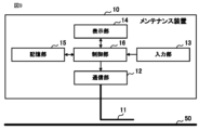
- the maintenance device 10 is a device that temporarily connects to the communication line 50 of the air conditioning system 1 to perform maintenance work, inspection work, work to identify the cause of a failure, etc. of the air conditioning system 1. It is. Although the maintenance device 10 is connected to the communication line 50B in FIG. 1, it can also be connected to the communication line 50A. As shown in FIG. 5, the maintenance device 10 includes a connection section 11, a communication section 12, an input section 13, a display section 14, a storage section 15, and a control section 16.
- the connection unit 11 is configured to electromagnetically connect to the communication line 50 of the air conditioning system 1 in a non-contact manner.
- the connecting portion 11 includes a cable portion whose one end is connected to the communication portion 12, and a clamp portion made of a highly conductive material provided at the other end of the cable.
- the connecting portion 11 connects to the communication line 50 in a non-contact manner by sandwiching and surrounding the communication line 50 with the clamp portion, that is, by clamping the communication line 50 .
- communication is performed between the components of the air conditioning system 1 using a communication method using high frequency signals, and the high frequency signals flow through the communication line 50.
- the communication unit 12 can receive the high frequency signal flowing through the communication line 50 via the connection unit 11. Further, the communication unit 12 can transmit a signal, which is an electromagnetic wave having the same frequency as the high-frequency signal flowing through the communication line 50, from the communication line 50 clamped at the connection unit 11 to the destination device.
- the connecting portion 11 is an example of a connecting means of the present disclosure.
- Figure 6 shows the characteristics of the cable used for the communication line 50, information indicating the ease with which crosstalk occurs in the cable in three stages of " ⁇ ", " ⁇ ", and " ⁇ " in order of ease of occurrence, and recommended information.
- 12 is a table summarizing the relationship between the mounting position of the connecting portion 11 and the mounting position of the connecting portion 11.
- the connecting portion 11 can be attached to any position on the communication line 50.
- connection part 11 to the part of the communication line 50 in the vicinity of the connection port of the terminal blocks 21, 31, 41 where the sheet is removed.
- the communication unit 12 communicates between the connection unit 11 and the communication line 50 using a communication method using electromagnetic waves having the same frequency as the high frequency signal used for communication in the air conditioning system 1. It communicates with each component of the air conditioning system 1 connected via. For example, when the connection unit 11 is connected to the communication line 50A, the communication unit 12 communicates with each component of the air conditioning system 1 using a communication method using a high frequency signal of the first frequency. Moreover, when the connection part 11 is connected to the communication line 50B, the communication part 12 communicates with each component of the air conditioning system 1 by a communication method using a high frequency signal of the second frequency.
- the communication unit 12 is an example of communication means of the present disclosure.
- the input unit 13 is, for example, an input device such as a keyboard, a mouse, a keypad, a push button, a touch panel, a touch pad, etc., and receives an input operation from a user and sends a signal related to the accepted input operation to the control unit 16.
- the display unit 14 is, for example, a liquid crystal display, an organic EL display, or the like, and displays screens for operating the outdoor unit 30 and indoor unit 40, screens for displaying operating status, etc. under the control of the control unit 16. indicate.
- the storage unit 15 is composed of an EEPROM (Electrically Erasable Programmable Read-Only Memory), a readable/writable nonvolatile semiconductor memory such as a flash memory, an HDD (Hard Disk Drive), and the like.
- the storage unit 15 stores management programs, data, etc. for maintaining and inspecting the outdoor unit 30 and the indoor unit 40.
- the control unit 16 is configured to include a CPU, ROM, RAM, etc. (all not shown), and performs overall control of the maintenance device 10. As shown in FIG. 7, the control unit 16 includes a communication determination unit 161, a connection position change notification unit 162, a frequency identification unit 163, and a maintenance processing unit 164 as functional configurations.
- the communication determination unit 161 determines whether the communication unit 12 can communicate well with the air conditioning system 1.
- the connection position change notification unit 162 executes a process for prompting the user to change the connection position of the connection unit 11 to the communication line 50 when the communication determination unit 161 determines that good communication with the air conditioning system 1 is not possible. do.
- the communication determination unit 161 is an example of communication determination means of the present disclosure.
- the connection position change notification unit 162 is an example of connection position change notification means of the present disclosure. The details of the processing executed by the communication determination section 161 and the connection position change notification section 162 will be described later.
- the frequency identification unit 163 identifies the frequency of the high frequency signal flowing through the communication line 50 to which the connection unit 11 is connected in a non-contact manner. That is, when the connecting section 11 is connected to the communication line 50A, the frequency specifying section 163 specifies the first frequency, and when the connecting section 11 is connected to the communication line 50B, the frequency specifying section 163 specifies the second frequency. Identify.
- the frequency specifying unit 163 is an example of a frequency specifying means of the present disclosure.
- the maintenance processing unit 164 executes various processes necessary for maintenance work, inspection work, etc. For example, the maintenance processing unit 164 executes a process of acquiring and analyzing operating data from the indoor unit 40 via the connection unit 11 and the communication unit 12, a process of transmitting a control command, and the like.
- a user who is an administrator, worker, etc. of the air conditioning system 1 clamps the communication line 50 of the air conditioning system 1 with the clamp part of the connection part 11 of the maintenance device 10 in order to perform maintenance work, inspection work, etc. of the air conditioning system 1. do. At this time, there is no need to stop the power supply to the air conditioning system 1.
- the user then operates the input unit 13 of the maintenance device 10 to instruct the start of maintenance work.
- the control unit 16 of the maintenance device 10 executes the maintenance process shown in FIG. 8. Note that the control unit 16 may automatically start the maintenance process when the connection unit 11 is clamped to the communication line 50 without waiting for an operation from the user.
- the communication determination unit 161 of the maintenance device 10 first determines whether the communication unit 12 can communicate well with the air conditioning system 1 connected via the connection unit 11 (step S101). Specifically, the communication determination unit 161 causes the communication unit 12 to transmit a response request signal to the outdoor unit 30. Then, the communication determining unit 161 makes the above determination based on the time from when the communication unit 12 transmits the response request signal to when the outdoor unit 30 receives the response signal. Note that the above-described determination method is an example, and the communication determination unit 161 may determine whether or not the communication unit 12 can communicate well with the air conditioning system 1 using other methods.
- connection position change notification unit 162 performs a process for prompting the user to change the connection position of the connection unit 11 (step S102).
- connection position change notification section 162 causes the display section 14 to display a message saying "Please clamp the communication line near the terminal block."
- the connection position change notification unit 162 may output a similar message by voice, or if the maintenance device 10 has an Internet connection function, a similar message may be output on the user's smartphone. The message may be sent by email, SMS, etc. The maintenance process then ends.
- the frequency identification unit 163 detects the high frequency that is flowing through the communication line 50 to which the connection unit 11 is connected in a non-contact manner.
- the frequency of the signal is specified (step S103).
- the frequency specifying unit 163 may analyze the response signal received from the outdoor unit 30 and specify the frequency in order to make the determination in step S101. If the connection unit 11 is connected to the communication line 50A, the first frequency is specified in step S103. If the connection unit 11 is connected to the communication line 50B, the second frequency is specified in step S103.
- Step S103 the user operates the input unit 13 of the maintenance device 10 to perform various operations for performing maintenance work, and the maintenance processing unit 164 executes various processes in accordance with the operations ( Step S104). Furthermore, at this time, the maintenance processing unit 164 controls the communication unit 12 as necessary to communicate with each component of the air conditioning system 1 connected via the connection unit 11 and the communication line 50.
- the maintenance processing unit 164 instructs the communication unit 12 to transmit data such as control commands and information acquisition request commands as necessary.
- the communication section 12 Upon receiving the instruction, the communication section 12 generates an electromagnetic wave having the same frequency as the frequency specified in step S103, on which the instructed data is superimposed, and causes the electromagnetic wave to be output from the connection section 11. Thereby, data can be transmitted to the target device via the communication line 50 that is connected to the connection unit 11 in a non-contact manner.
- the maintenance processing unit 164 acquires data such as operating data of the indoor unit 40 and environmental information from the high frequency signal received by the communication unit 12 via the connection unit 11, as necessary.
- step S105 the user performs an operation to end the maintenance process from the input unit 13 (step S105; Yes), and the maintenance process ends.
- the maintenance device 10 by utilizing crosstalk, power can be supplied to the air conditioning system 1 by simply clamping the communication line 50 through which a high-frequency signal is flowing at the connection part 11. It becomes possible to easily connect to this air conditioning system 1 in a communicable manner while maintaining the same.
- the maintenance device 10 when the connection state with the air conditioning system 1 is not good, a process for prompting the user to change the connection position of the connection part 11 is executed. Therefore, the effect of improving communication problems with the air conditioning system 1 can be expected.
- connection unit 11 was electromagnetically connected to the communication line 50 in a non-contact manner by clamping the communication line 50.
- the connecting portion 11 may be electromagnetically connected to the communication line 50 in a non-contact manner by other methods.
- crosstalk with the communication line 50 will occur even if the connection part 11 is made up of only a cable part and at least a part of the connection part 11 is placed along the communication line.
- the connecting portion 11 can be electromagnetically connected to the communication line 50 without contact. In this case, it is desirable that the cable portion of the connecting portion 11 be a CVV cable, which is likely to cause crosstalk.
- the communication lines 50A and 50B of the air conditioning system 1 communicate using high frequency signals of different frequencies, but the communication lines 50A and 50B both communicate using high frequency signals of the same frequency. You can. In this case, no matter which communication line 50A or 50B the connection unit 11 is connected to, the frequency of the received high-frequency signal is the same, so the process of identifying the frequency in step S103 of the maintenance process can be omitted. . Furthermore, communication using high-frequency signals may be performed using only one of the communication lines 50A and 50B of the air conditioning system 1. In this case, the connection unit 11 needs to be connected to the communication lines 50A and 50B that communicate using high-frequency signals.
- the portion of the communication line 50 within a predetermined range from the connection port of the terminal blocks 21, 31, 41 can be distinguished from other portions. May be displayed. For example, in FIG. 10, a marker M1 is attached to the communication line 50 within 10 cm from the connection port of the terminal blocks 21, 31, 41. The connecting portion 11 of the maintenance device 10 is clamped to the communication line 50 of this marker portion. By doing so, the user can connect the connection unit 11 to an appropriate position of the communication line 50 where crosstalk is likely to occur.
- a terminal block 70 is connected to the terminal block 41 of the indoor unit 40b, which is a component of the air conditioning system 1, via a coupling circuit 60.
- the maintenance device 10 may be communicably connected to the connection port of the terminal block 70 via a general cable 80. This makes it possible to easily connect the maintenance device 10 to the air conditioning system 1 in a communicable manner while maintaining power supply to the air conditioning system 1. Note that in this case, the maintenance device 10 does not need to be provided with the connection portion 11. Further, the terminal block 70 for connecting the maintenance device 10 may be similarly connected to the terminal blocks 21, 31, and 41 of component devices other than the indoor unit 40b.
- the air conditioning system 1 including one central control device 20, three outdoor units 30a to 30c, and six indoor units 40a to 40f is used as an example.
- the number of these devices constituting the air conditioning system 1 is arbitrary.
- the air conditioning system 1 may include devices other than the central control device 20, the outdoor unit 30, and the indoor unit 40.
Landscapes
- Engineering & Computer Science (AREA)
- Chemical & Material Sciences (AREA)
- Combustion & Propulsion (AREA)
- Mechanical Engineering (AREA)
- General Engineering & Computer Science (AREA)
- Air Conditioning Control Device (AREA)
Abstract
This maintenance device (10) comprises: a connection means (11) that contactlessly connects to communication lines (50A, 50B) that transmit/receive high-frequency signals in an air-conditioning system (1), in which at least some of a plurality of constituent apparatuses are connected by the communication lines (50A, 50B); and a communication means that communicates with the air-conditioning system (1) via the connection means (11) by using electromagnetic waves having the same frequency as the high-frequency signals.
Description
本開示は、メンテナンス装置及びメンテナンスシステムに関する。
The present disclosure relates to a maintenance device and a maintenance system.
集中伝送ライン、内外伝送ライン等の通信線によって接続された集中管理装置と複数の室外機と複数の室内機とを備えたビル用の空調システムが知られている。このような空調システムでは、保守作業、点検作業、障害が発生した場合の原因特定作業などをする際に、メンテナンス用の機器であるメンテナンス装置を一時的に空調システムの通信線に接続して、当該メンテナンス装置からこれらの作業をする場合がある。例えば、特許文献1には、仮説ケーブルを介して空調システムに収集装置を一時的に接続し、収集装置でデータ収集処理を行うデータ収集システムについて記載されている。
Air conditioning systems for buildings are known that include a central control device, multiple outdoor units, and multiple indoor units connected by communication lines such as centralized transmission lines and internal/external transmission lines. In such air conditioning systems, when performing maintenance work, inspection work, work to identify the cause of a failure, etc., a maintenance device, which is a maintenance device, is temporarily connected to the communication line of the air conditioning system. These operations may be performed from the maintenance device. For example, Patent Document 1 describes a data collection system in which a collection device is temporarily connected to an air conditioning system via a hypothetical cable, and the collection device performs data collection processing.
空調システムでは、通信線によって各機器へ電力供給を行うものが知られている。このような通信線にメンテナンス装置を接続する際には、各機器への電力供給を遮断してから接続する必要がある。従って、その間は空調システムを利用できなくなってしまうという課題がある。また、電力供給を維持したまま、活線での作業によってメンテナンス装置を空調システムに接続することも考えられる。しかしこの場合は作業員に特別な技術、資格が要求されるとともに、感電防止のための防護対策が必要となる。また、接続作業を誤ると機器が故障してしまう虞がある。
Some air conditioning systems are known that supply power to each device via communication lines. When connecting a maintenance device to such a communication line, it is necessary to cut off power supply to each device before connecting. Therefore, there is a problem that the air conditioning system cannot be used during that time. It is also conceivable to connect the maintenance device to the air conditioning system by working with a live line while maintaining the power supply. However, in this case, special skills and qualifications are required of the workers, and protective measures are required to prevent electric shock. Furthermore, if the connection is made incorrectly, there is a risk that the equipment will malfunction.
本開示は、上記実情に鑑みてなされたものであり、空調システムへの電力供給を維持したまま、容易にこの空調システムと通信可能に接続することが可能なメンテナンス装置及びメンテナンスシステムを提供することを目的とする。
The present disclosure has been made in view of the above circumstances, and an object of the present disclosure is to provide a maintenance device and a maintenance system that can be easily connected to an air conditioning system for communication while maintaining power supply to the air conditioning system. With the goal.
上記目的を達成するため、本開示に係るメンテナンス装置は、
複数の構成機器のうちの少なくとも一部が高周波信号を送受信する通信線で接続されている空調システムの当該通信線に非接触で接続する接続手段と、
前記接続手段を介して、前記高周波信号と同一周波数の電磁波によって前記空調システムと通信する通信手段と、
を備える。 In order to achieve the above object, the maintenance device according to the present disclosure includes:
A connection means for connecting in a contactless manner to a communication line of an air conditioning system in which at least some of the plurality of component devices are connected by a communication line that transmits and receives high-frequency signals;
Communication means for communicating with the air conditioning system via the connection means using electromagnetic waves having the same frequency as the high frequency signal;
Equipped with.
本開示によれば、空調システムへの電力供給を維持したまま、容易にこの空調システムと通信可能に接続することが可能となる。
According to the present disclosure, it is possible to easily connect to the air conditioning system for communication while maintaining power supply to the air conditioning system.
以下、本開示の実施形態について、図面を参照しながら詳細に説明する。なお、図中同一または相当部分には同一符号を付す。
Hereinafter, embodiments of the present disclosure will be described in detail with reference to the drawings. In addition, the same reference numerals are given to the same or corresponding parts in the figures.
図1は、本開示の実施形態に係るメンテナンスシステム100の全体構成を示す図である。メンテナンスシステム100は、空調システム1と、当該空調システム1に一時的に接続されているメンテナンス装置10とを備える。
FIG. 1 is a diagram showing the overall configuration of a maintenance system 100 according to an embodiment of the present disclosure. The maintenance system 100 includes an air conditioning system 1 and a maintenance device 10 temporarily connected to the air conditioning system 1.
空調システム1は、例えば、オフィスビル、商業施設等の建物の空調を行うビル用のマルチ空調システムである。空調システム1は、複数の構成機器として、集中管理装置20と、複数の室外機30a~30cと、複数の室内機40a~40fとを備える。
The air conditioning system 1 is, for example, a multi-air conditioning system for buildings that air-conditions buildings such as office buildings and commercial facilities. The air conditioning system 1 includes a central control device 20, a plurality of outdoor units 30a to 30c, and a plurality of indoor units 40a to 40f as a plurality of component devices.
集中管理装置20と各室外機30a~30cとは、いわゆる集中伝送ラインである通信線50Aを介してデイジーチェーン接続されている。集中管理装置20と各室外機30a~30cとは、通信線50Aを介して、100kHz以上である第1周波数の高周波信号を送受信することによって通信を行う。また、通信線50Aは、図示せぬ電源に接続されており、集中管理装置20と室外機30a~30cとに電力を供給する。
The central control device 20 and each of the outdoor units 30a to 30c are connected in a daisy chain via a communication line 50A, which is a so-called centralized transmission line. The central management device 20 and each of the outdoor units 30a to 30c communicate with each other by transmitting and receiving a high frequency signal of a first frequency of 100 kHz or more via the communication line 50A. Further, the communication line 50A is connected to a power source (not shown), and supplies power to the central management device 20 and the outdoor units 30a to 30c.
室外機30aと室内機40a,40b、室外機30bと室内機40c,40d、および室外機30cと室内機40e,40fは、いわゆる内外伝送ラインである通信線50Bによって接続されている。室外機30aと室内機40a,40b、室外機30bと室内機40c,40d、および室外機30cと室内機40e,40fは、それぞれ、通信線50Bを介して、第1周波数とは異なる100kHz以上である第2周波数の高周波信号を送受信することによって通信を行う。また、通信線50Bは、図示せぬ電源に接続されており、室内機40a~40fに電力を供給する。
The outdoor unit 30a and indoor units 40a and 40b, the outdoor unit 30b and indoor units 40c and 40d, and the outdoor unit 30c and indoor units 40e and 40f are connected by a communication line 50B, which is a so-called internal and external transmission line. The outdoor unit 30a and the indoor units 40a, 40b, the outdoor unit 30b and the indoor units 40c, 40d, and the outdoor unit 30c and the indoor units 40e, 40f each communicate at a frequency of 100 kHz or more different from the first frequency via the communication line 50B. Communication is performed by transmitting and receiving high frequency signals of a certain second frequency. Further, the communication line 50B is connected to a power source (not shown), and supplies power to the indoor units 40a to 40f.
以下、室外機30a~30cにて共通する説明については、特に個々を指定せずに室外機30と表記する。室内機40a~40fも同様に、共通する説明については、特に個々を指定せずに室内機40と表記する。また、通信線50A,50Bを区別しない場合は、通信線50と表記する。
Hereinafter, descriptions common to the outdoor units 30a to 30c will be referred to as the outdoor units 30 without specifically specifying each one. Similarly, the indoor units 40a to 40f will be referred to as indoor units 40 for common explanations without specifying each individual unit. Moreover, when the communication lines 50A and 50B are not distinguished, they are referred to as communication lines 50.
続いて、空調システム1の各構成機器について説明する。
Next, each component of the air conditioning system 1 will be explained.
集中管理装置20は、室外機30と室内機40を集中して管理するための装置であり、例えば、建物内の管理室に設置される。集中管理装置20は、図2に示すように、端子台21と、通信部22と、入力部23と、表示部24と、記憶部25と、制御部26とを備える。
The centralized management device 20 is a device for centrally managing the outdoor unit 30 and the indoor unit 40, and is installed, for example, in a management room in a building. As shown in FIG. 2, the centralized management device 20 includes a terminal block 21, a communication section 22, an input section 23, a display section 24, a storage section 25, and a control section 26.
端子台21は、集中管理装置20が各室外機30と接続するためのインタフェースである。端子台21の接続口は、集中管理装置20の筐体の外部に露出しており、当該接続口には通信線50Aが接続されている。なお、端子台21を設けずに、通信部22に通信線50Aを直接接続してもよい。
The terminal block 21 is an interface for connecting the central management device 20 to each outdoor unit 30. A connection port of the terminal block 21 is exposed to the outside of the casing of the central management device 20, and a communication line 50A is connected to the connection port. Note that the communication line 50A may be directly connected to the communication section 22 without providing the terminal block 21.
通信部22は、制御部26の制御の下、第1周波数の高周波信号を用いた通信方式によって、端子台21と通信線50Aとを介して接続されている各室外機30と通信を行う。
Under the control of the control unit 26, the communication unit 22 communicates with each outdoor unit 30 connected via the terminal block 21 and the communication line 50A using a communication method using a high-frequency signal of the first frequency.
入力部23は、例えば、キーボード、マウス、キーパッド、押しボタン、タッチパネル、タッチパッド等の入力デバイスであり、ユーザからの入力操作を受け付け、受け付けた入力操作に係る信号を制御部26に出力する。表示部24は、例えば、CRTディスプレイ、液晶ディスプレイ、有機ELディスプレイ、プラズマディスプレイ等であり、制御部26の制御の下、室外機30、及び室内機40を操作するための画面、状態を表示するための画面などを表示する。
The input unit 23 is, for example, an input device such as a keyboard, a mouse, a keypad, a push button, a touch panel, a touch pad, etc., and receives an input operation from a user and outputs a signal related to the received input operation to the control unit 26. . The display unit 24 is, for example, a CRT display, a liquid crystal display, an organic EL display, a plasma display, etc., and displays screens and status for operating the outdoor unit 30 and the indoor unit 40 under the control of the control unit 26. Display screens etc.
記憶部25は、EEPROM(Electrically Erasable Programmable Read-Only Memory)、フラッシュメモリ等の読み書き可能な不揮発性の半導体メモリ、HDD(Hard Disk Drive)等で構成される。記憶部25には、室外機30を管理するための管理プログラム、データ等が記憶される。
The storage unit 25 is composed of an EEPROM (Electrically Erasable Programmable Read-Only Memory), a readable/writable nonvolatile semiconductor memory such as a flash memory, an HDD (Hard Disk Drive), and the like. The storage unit 25 stores management programs, data, etc. for managing the outdoor unit 30.
制御部26は、CPU(Central Processing Unit)、ROM(Read Only Memory)、RAM(Random Access Memory)等を含んで構成され、集中管理装置20を統括制御する。
The control unit 26 is configured to include a CPU (Central Processing Unit), a ROM (Read Only Memory), a RAM (Random Access Memory), etc., and performs overall control of the central management device 20.
室外機30は、図3に示すように、端子台31と、第1通信部32と、第2通信部33と、メインユニット34と、制御部35とを備える。
As shown in FIG. 3, the outdoor unit 30 includes a terminal block 31, a first communication section 32, a second communication section 33, a main unit 34, and a control section 35.
端子台31は、室外機30が集中管理装置20、及び室内機40と接続するためのインタフェースである。端子台31の接続口は、室外機30の筐体の外部に露出しており、当該接続口には通信線50Aと通信線50Bとが接続されている。なお、端子台31を設けずに、第1通信部32に通信線50A、第2通信部33に通信線50Bを直接接続してもよい。
The terminal block 31 is an interface for connecting the outdoor unit 30 to the central management device 20 and the indoor unit 40. A connection port of the terminal block 31 is exposed to the outside of the casing of the outdoor unit 30, and a communication line 50A and a communication line 50B are connected to the connection port. Note that the communication line 50A may be directly connected to the first communication section 32 and the communication line 50B may be directly connected to the second communication section 33 without providing the terminal block 31.
第1通信部32は、制御部35の制御の下、第1周波数の高周波信号を用いた通信方式によって、端子台31と通信線50Aとを介して接続されている集中管理装置20と通信を行う。第2通信部33は、制御部35の制御の下、第2周波数の高周波信号を用いた通信方式によって、端子台31と通信線50Bとを介して接続されている各室内機40と通信を行う。
The first communication unit 32 communicates with the central management device 20 connected via the terminal block 31 and the communication line 50A under the control of the control unit 35 using a communication method using a high-frequency signal of a first frequency. conduct. Under the control of the control unit 35, the second communication unit 33 communicates with each indoor unit 40 connected via the terminal block 31 and the communication line 50B using a communication method using a high-frequency signal of a second frequency. conduct.
メインユニット34は、一般的な室外機30の本来的な機能を実現するための構成部であり、圧縮機、熱交換器、膨張弁、四方弁等で構成される冷媒回路、ファン、各種のセンサ(電流センサ、温度センサ、圧力センサ、周波数センサ、加速度センサ等)等を備える。
The main unit 34 is a component for realizing the original functions of the general outdoor unit 30, and includes a refrigerant circuit including a compressor, a heat exchanger, an expansion valve, a four-way valve, etc., a fan, and various other components. Equipped with sensors (current sensor, temperature sensor, pressure sensor, frequency sensor, acceleration sensor, etc.).
制御部35は、CPU、ROM、RAM等(何れも図示せず)を含んで構成され、当該室外機30を統括制御する。
The control unit 35 is configured to include a CPU, ROM, RAM, etc. (all not shown), and centrally controls the outdoor unit 30.
室内機40は、図4に示すように、端子台41と、通信部42と、メインユニット43と、制御部44とを備える。
As shown in FIG. 4, the indoor unit 40 includes a terminal block 41, a communication section 42, a main unit 43, and a control section 44.
端子台41は、室内機40が室外機30と接続するためのインタフェースである。端子台41の接続口は、室内機40の筐体の外部に露出しており、当該接続口に通信線50Bが接続されている。なお、端子台41を設けずに、通信部42に通信線50Bを直接接続してもよい。
The terminal block 41 is an interface for connecting the indoor unit 40 to the outdoor unit 30. A connection port of the terminal block 41 is exposed to the outside of the casing of the indoor unit 40, and a communication line 50B is connected to the connection port. Note that the communication line 50B may be directly connected to the communication section 42 without providing the terminal block 41.
通信部42は、制御部44の制御の下、第2周波数の高周波信号を用いた通信方式によって、端子台41と通信線50Bとを介して接続されている室外機30と通信を行う。
The communication unit 42 communicates with the outdoor unit 30 connected via the terminal block 41 and the communication line 50B under the control of the control unit 44 using a communication method using a high-frequency signal of the second frequency.
メインユニット43は、一般的な室内機40の本来的な機能を実現するための構成部であり、例えば、ファン、熱交換器、温度センサ、湿度センサ等を備える。メインユニット43に含まれる各センサの計測結果は、通信線50Bによって接続されている室外機30に周期的に送信される。
The main unit 43 is a component for realizing the original functions of a general indoor unit 40, and includes, for example, a fan, a heat exchanger, a temperature sensor, a humidity sensor, and the like. The measurement results of each sensor included in the main unit 43 are periodically transmitted to the outdoor unit 30 connected via a communication line 50B.
制御部は44、CPU、ROM、RAM等(何れも図示せず)を含んで構成され、当該室内機40を統括制御する。
The control unit 44 includes a CPU, ROM, RAM, etc. (all not shown), and controls the indoor unit 40 in an integrated manner.
メンテナンス装置10は、空調システム1の保守作業、点検作業、障害が発生した場合の原因特定作業などをする際に、空調システム1の通信線50に一時的に接続してこれらの作業を行う装置である。なお、図1では、メンテナンス装置10は通信線50Bに接続しているが、通信線50Aに接続することも可能である。メンテナンス装置10は、図5に示すように、接続部11と、通信部12と、入力部13と、表示部14と、記憶部15と、制御部16とを備える。
The maintenance device 10 is a device that temporarily connects to the communication line 50 of the air conditioning system 1 to perform maintenance work, inspection work, work to identify the cause of a failure, etc. of the air conditioning system 1. It is. Although the maintenance device 10 is connected to the communication line 50B in FIG. 1, it can also be connected to the communication line 50A. As shown in FIG. 5, the maintenance device 10 includes a connection section 11, a communication section 12, an input section 13, a display section 14, a storage section 15, and a control section 16.
接続部11は、空調システム1の通信線50に非接触で電磁的に接続するための構成である。具体的には、接続部11は、一端が通信部12に接続されているケーブル部分と、当該ケーブルの他端に設けられている導電性の高い素材からなるクランプ部分とを備える。接続部11は、クランプ部分で通信線50を挟み込むように囲む、即ちクランプすることで通信線50に非接触で接続する。上述したように、空調システム1の構成機器間では、高周波信号を用いた通信方式による通信が行われており、通信線50には高周波信号が流れている。そのため、通信線50をクランプすると、通信線50とクランプ部分との間でクロストークが発生して、通信線50に流れている高周波信号が接続部11に漏電する。これにより、通信部12は、接続部11を介して通信線50に流れる高周波信号を受信することができる。また、通信部12は、通信線50に流れている高周波信号と同一周波数の電磁波である信号を、接続部11でクランプされている通信線50から送信先の機器に送信することができる。接続部11は、本開示の接続手段の一例である。
The connection unit 11 is configured to electromagnetically connect to the communication line 50 of the air conditioning system 1 in a non-contact manner. Specifically, the connecting portion 11 includes a cable portion whose one end is connected to the communication portion 12, and a clamp portion made of a highly conductive material provided at the other end of the cable. The connecting portion 11 connects to the communication line 50 in a non-contact manner by sandwiching and surrounding the communication line 50 with the clamp portion, that is, by clamping the communication line 50 . As described above, communication is performed between the components of the air conditioning system 1 using a communication method using high frequency signals, and the high frequency signals flow through the communication line 50. Therefore, when the communication line 50 is clamped, crosstalk occurs between the communication line 50 and the clamped portion, and the high frequency signal flowing through the communication line 50 leaks to the connection part 11. Thereby, the communication unit 12 can receive the high frequency signal flowing through the communication line 50 via the connection unit 11. Further, the communication unit 12 can transmit a signal, which is an electromagnetic wave having the same frequency as the high-frequency signal flowing through the communication line 50, from the communication line 50 clamped at the connection unit 11 to the destination device. The connecting portion 11 is an example of a connecting means of the present disclosure.
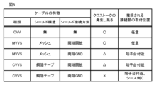
なお、通信線50に用いるケーブルの種類、シールドの接続方法等によって、クロストークの発生のし易さは異なるため、これに応じて接続部11を取り付ける位置を適宜変更するのが望ましい。図6は、通信線50に用いるケーブルの特徴と、当該ケーブルでのクロストークの発生し易さを発生し易い順に「○」、「△」、「×」の3段階で示す情報と、推奨される接続部11の取り付け位置との関係をまとめた表である。
Note that since the ease with which crosstalk occurs varies depending on the type of cable used for the communication line 50, the method of connecting the shield, etc., it is desirable to appropriately change the position at which the connecting portion 11 is attached accordingly. Figure 6 shows the characteristics of the cable used for the communication line 50, information indicating the ease with which crosstalk occurs in the cable in three stages of "○", "△", and "×" in order of ease of occurrence, and recommended information. 12 is a table summarizing the relationship between the mounting position of the connecting portion 11 and the mounting position of the connecting portion 11.
この表に示すように、シールドが無いCVVケーブル、若しくはシールド構造がメッシュタイプであるMVVSケーブルであってシールド接続方法が両端開放であるものを通信線50に採用した場合は、クロストークが非常に発生し易い。この場合、通信線50の任意の位置に接続部11を取り付けることができる。
As shown in this table, when a CVV cable without a shield or an MVVS cable with a mesh type shield structure and the shield connection method is open at both ends is adopted as the communication line 50, crosstalk is extremely high. Easy to occur. In this case, the connecting portion 11 can be attached to any position on the communication line 50.
また、MVVSケーブルであってシールド接続方法が両端グラウンドであるもの、若しくはシールド構造が銅箔テープであるCVVSケーブルであってシールド接続方法が両端開放であるものを通信線50に採用した場合は、上述したケーブルよりは劣るもののクロストークはある程度発生する。この場合、クロストークが発生し易い端子台21,31,41の接続口付近の通信線50に接続部11を取り付けるのが望ましい。
In addition, if an MVVS cable in which the shield connection method is grounded at both ends, or a CVVS cable in which the shield structure is copper foil tape and the shield connection method is open at both ends is adopted as the communication line 50, Although it is worse than the cables mentioned above, crosstalk still occurs to some extent. In this case, it is desirable to attach the connection part 11 to the communication line 50 near the connection ports of the terminal blocks 21, 31, and 41 where crosstalk is likely to occur.
また、CVVSケーブルであってシールド接続方法が両端グラウンドであるものを通信線50に採用した場合は、ほとんどクロストークは発生しない。この場合、端子台21,31,41の接続口付近の通信線50のシーツを剥いだ部分に接続部11を取り付けるのが望ましい。
Further, if a CVVS cable in which the shield is connected to ground at both ends is used for the communication line 50, almost no crosstalk occurs. In this case, it is desirable to attach the connection part 11 to the part of the communication line 50 in the vicinity of the connection port of the terminal blocks 21, 31, 41 where the sheet is removed.
図5に戻り、通信部12は、制御部16の制御の下、空調システム1での通信で使用されている高周波信号と同一周波数の電磁波を用いた通信方式によって、接続部11と通信線50とを介して接続されている空調システム1の各構成機器と通信を行う。例えば、接続部11が通信線50Aに接続されている場合、通信部12は、第1周波数の高周波数信号を用いた通信方式によって空調システム1の各構成機器と通信を行う。また、接続部11が通信線50Bに接続されている場合、通信部12は、第2周波数の高周波数信号を用いた通信方式によって空調システム1の各構成機器と通信を行う。通信部12は、本開示の通信手段の一例である。
Returning to FIG. 5, under the control of the control unit 16, the communication unit 12 communicates between the connection unit 11 and the communication line 50 using a communication method using electromagnetic waves having the same frequency as the high frequency signal used for communication in the air conditioning system 1. It communicates with each component of the air conditioning system 1 connected via. For example, when the connection unit 11 is connected to the communication line 50A, the communication unit 12 communicates with each component of the air conditioning system 1 using a communication method using a high frequency signal of the first frequency. Moreover, when the connection part 11 is connected to the communication line 50B, the communication part 12 communicates with each component of the air conditioning system 1 by a communication method using a high frequency signal of the second frequency. The communication unit 12 is an example of communication means of the present disclosure.
入力部13は、例えば、キーボード、マウス、キーパッド、押しボタン、タッチパネル、タッチパッド等の入力デバイスであり、ユーザからの入力操作を受け付け、受け付けた入力操作に係る信号を制御部16に送出する。表示部14は、例えば、液晶ディスプレイ、有機ELディスプレイ等であり、制御部16の制御の下、室外機30、及び室内機40を操作するための画面、運転状態を表示するための画面などを表示する。
The input unit 13 is, for example, an input device such as a keyboard, a mouse, a keypad, a push button, a touch panel, a touch pad, etc., and receives an input operation from a user and sends a signal related to the accepted input operation to the control unit 16. . The display unit 14 is, for example, a liquid crystal display, an organic EL display, or the like, and displays screens for operating the outdoor unit 30 and indoor unit 40, screens for displaying operating status, etc. under the control of the control unit 16. indicate.
記憶部15は、EEPROM(Electrically Erasable Programmable Read-Only Memory)、フラッシュメモリ等の読み書き可能な不揮発性の半導体メモリ、HDD(Hard Disk Drive)等で構成される。記憶部15には、室外機30と室内機40とを保守、点検するための管理プログラム、データ等が記憶される。
The storage unit 15 is composed of an EEPROM (Electrically Erasable Programmable Read-Only Memory), a readable/writable nonvolatile semiconductor memory such as a flash memory, an HDD (Hard Disk Drive), and the like. The storage unit 15 stores management programs, data, etc. for maintaining and inspecting the outdoor unit 30 and the indoor unit 40.
制御部16は、CPU、ROM、RAM等(何れも図示せず)を含んで構成され、当該メンテナンス装置10を統括制御する。図7に示すように、制御部16は、機能的な構成として、通信判別部161と、接続位置変更報知部162と、周波数特定部163と、メンテナンス処理部164とを備える。
The control unit 16 is configured to include a CPU, ROM, RAM, etc. (all not shown), and performs overall control of the maintenance device 10. As shown in FIG. 7, the control unit 16 includes a communication determination unit 161, a connection position change notification unit 162, a frequency identification unit 163, and a maintenance processing unit 164 as functional configurations.
通信判別部161は、通信部12が空調システム1と良好に通信できるか否かを判別する。接続位置変更報知部162は、通信判別部161が、空調システム1と良好に通信できないと判別した場合に、接続部11の通信線50への接続位置の変更をユーザに促すための処理を実行する。通信判別部161は、本開示の通信判別手段の一例である。接続位置変更報知部162は、本開示の接続位置変更報知手段の一例である。通信判別部161と接続位置変更報知部162が実行する処理の詳細については後述する。
The communication determination unit 161 determines whether the communication unit 12 can communicate well with the air conditioning system 1. The connection position change notification unit 162 executes a process for prompting the user to change the connection position of the connection unit 11 to the communication line 50 when the communication determination unit 161 determines that good communication with the air conditioning system 1 is not possible. do. The communication determination unit 161 is an example of communication determination means of the present disclosure. The connection position change notification unit 162 is an example of connection position change notification means of the present disclosure. The details of the processing executed by the communication determination section 161 and the connection position change notification section 162 will be described later.
周波数特定部163は、接続部11が非接触で接続している通信線50に流れている高周波信号の周波数を特定する。即ち、接続部11が通信線50Aに接続されている場合、周波数特定部163は第1周波数を特定し、接続部11が通信線50Bに接続されている場合、周波数特定部163は第2周波数を特定する。周波数特定部163は、本開示の周波数特定手段の一例である。
The frequency identification unit 163 identifies the frequency of the high frequency signal flowing through the communication line 50 to which the connection unit 11 is connected in a non-contact manner. That is, when the connecting section 11 is connected to the communication line 50A, the frequency specifying section 163 specifies the first frequency, and when the connecting section 11 is connected to the communication line 50B, the frequency specifying section 163 specifies the second frequency. Identify. The frequency specifying unit 163 is an example of a frequency specifying means of the present disclosure.
メンテナンス処理部164は、保守作業、点検作業等をするために必要な各種の処理を実行する。例えば、メンテナンス処理部164は、接続部11と通信部12とを介して室内機40から運転データを取得して解析する処理、制御コマンドを送信する処理等を実行する。
The maintenance processing unit 164 executes various processes necessary for maintenance work, inspection work, etc. For example, the maintenance processing unit 164 executes a process of acquiring and analyzing operating data from the indoor unit 40 via the connection unit 11 and the communication unit 12, a process of transmitting a control command, and the like.
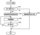
続いて、メンテナンス装置10が実行するメンテナンス処理について説明する。空調システム1の管理者、作業員等であるユーザは、空調システム1の保守作業、点検作業等をするために、メンテナンス装置10の接続部11のクランプ部分で空調システム1の通信線50をクランプする。このとき、空調システム1への電力供給を止める必要はない。そして、ユーザは、メンテナンス装置10の入力部13を操作してメンテナンス作業の開始を指示する。当該指示を受けて、メンテナンス装置10の制御部16は、図8に示すメンテナンス処理を実行する。なお、制御部16は、ユーザからの操作を待たずに、接続部11が通信線50へクランプしたときに、自動的にメンテナンス処理を開始してもよい。
Next, maintenance processing executed by the maintenance device 10 will be explained. A user who is an administrator, worker, etc. of the air conditioning system 1 clamps the communication line 50 of the air conditioning system 1 with the clamp part of the connection part 11 of the maintenance device 10 in order to perform maintenance work, inspection work, etc. of the air conditioning system 1. do. At this time, there is no need to stop the power supply to the air conditioning system 1. The user then operates the input unit 13 of the maintenance device 10 to instruct the start of maintenance work. Upon receiving the instruction, the control unit 16 of the maintenance device 10 executes the maintenance process shown in FIG. 8. Note that the control unit 16 may automatically start the maintenance process when the connection unit 11 is clamped to the communication line 50 without waiting for an operation from the user.
メンテナンス処理が開始されると、まずメンテナンス装置10の通信判別部161は、通信部12が、接続部11を介して接続されている空調システム1と良好に通信できるか否かを判別する(ステップS101)。具体的には、通信判別部161は、通信部12から応答要求信号を室外機30に送信させる。そして、通信判別部161は、通信部12が応答要求信号を送信してから、室外機30が返信した応答信号を受信するまでの時間に基づいて、上記判別をする。なお、上述した判別の手法は一例であり、通信判別部161は、他の手法によって、通信部12が空調システム1と良好に通信できるか否かを判別してもよい。
When the maintenance process is started, the communication determination unit 161 of the maintenance device 10 first determines whether the communication unit 12 can communicate well with the air conditioning system 1 connected via the connection unit 11 (step S101). Specifically, the communication determination unit 161 causes the communication unit 12 to transmit a response request signal to the outdoor unit 30. Then, the communication determining unit 161 makes the above determination based on the time from when the communication unit 12 transmits the response request signal to when the outdoor unit 30 receives the response signal. Note that the above-described determination method is an example, and the communication determination unit 161 may determine whether or not the communication unit 12 can communicate well with the air conditioning system 1 using other methods.
通信部12が空調システム1と良好に通信できないと判別した場合(ステップS101;No)、メンテナンス装置10からメンテナンス作業をすることは困難である。またこの場合、高周波信号を受信しにくい端子台21,31,41から離れた位置にある通信線50に接続部11が取り付けられている可能性がある。そのため、接続位置変更報知部162は、接続部11の接続位置の変更をユーザに促すための処理を行う(ステップS102)。具体的には、接続位置変更報知部162は、「端子台近辺の通信線をクランプして下さい」とのメッセージを表示部14に表示させる。なお、メンテナンス装置10がスピーカを備えている場合、接続位置変更報知部162は、同様のメッセージを音声で出力させてもよいし、インターネット接続機能を有している場合は、ユーザのスマートフォンに同様のメッセージをメール、SMS等で送信してもよい。そしてメンテナンス処理は終了する。
If it is determined that the communication unit 12 cannot communicate well with the air conditioning system 1 (step S101; No), it is difficult to perform maintenance work from the maintenance device 10. Furthermore, in this case, there is a possibility that the connecting portion 11 is attached to the communication line 50 at a position away from the terminal blocks 21, 31, and 41, where it is difficult to receive high-frequency signals. Therefore, the connection position change notification unit 162 performs a process for prompting the user to change the connection position of the connection unit 11 (step S102). Specifically, the connection position change notification section 162 causes the display section 14 to display a message saying "Please clamp the communication line near the terminal block." Note that if the maintenance device 10 is equipped with a speaker, the connection position change notification unit 162 may output a similar message by voice, or if the maintenance device 10 has an Internet connection function, a similar message may be output on the user's smartphone. The message may be sent by email, SMS, etc. The maintenance process then ends.
一方、接続部11が空調システム1と良好に通信できると判別した場合(ステップS101;Yes)、周波数特定部163は、接続部11が非接触で接続している通信線50に流れている高周波信号の周波数を特定する(ステップS103)。例えば、周波数特定部163は、ステップS101の判別をするために室外機30から受信した応答信号を解析して、その周波数を特定すればよい。接続部11が通信線50Aに接続されている場合、ステップS103では第1周波数が特定される。接続部11が通信線50Bに接続されている場合、ステップS103では第2周波数が特定される。
On the other hand, if it is determined that the connection unit 11 can communicate well with the air conditioning system 1 (step S101; Yes), the frequency identification unit 163 detects the high frequency that is flowing through the communication line 50 to which the connection unit 11 is connected in a non-contact manner. The frequency of the signal is specified (step S103). For example, the frequency specifying unit 163 may analyze the response signal received from the outdoor unit 30 and specify the frequency in order to make the determination in step S101. If the connection unit 11 is connected to the communication line 50A, the first frequency is specified in step S103. If the connection unit 11 is connected to the communication line 50B, the second frequency is specified in step S103.
ステップS103の後、ユーザは、メンテナンス装置10の入力部13を操作してメンテナンス用の作業をするための各種の操作を行い、当該操作に応じてメンテナンス処理部164は各種の処理を実行する(ステップS104)。また、この際、必要に応じてメンテナンス処理部164は、通信部12を制御して、接続部11と通信線50とを介して接続されている空調システム1の各構成機器と通信を行う。
After step S103, the user operates the input unit 13 of the maintenance device 10 to perform various operations for performing maintenance work, and the maintenance processing unit 164 executes various processes in accordance with the operations ( Step S104). Furthermore, at this time, the maintenance processing unit 164 controls the communication unit 12 as necessary to communicate with each component of the air conditioning system 1 connected via the connection unit 11 and the communication line 50.
例えば、メンテナンス処理部164は、必要に応じて、制御コマンド、情報取得要求コマンド等のデータの送信を通信部12に指示する。当該指示を受けた通信部12は、指示されたデータを重畳した、ステップS103で特定した周波数と同一周波数の電磁波を生成して接続部11から出力させる。これにより、接続部11と非接触で接続されている通信線50を介して、対象とする機器にデータを送信することができる。
For example, the maintenance processing unit 164 instructs the communication unit 12 to transmit data such as control commands and information acquisition request commands as necessary. Upon receiving the instruction, the communication section 12 generates an electromagnetic wave having the same frequency as the frequency specified in step S103, on which the instructed data is superimposed, and causes the electromagnetic wave to be output from the connection section 11. Thereby, data can be transmitted to the target device via the communication line 50 that is connected to the connection unit 11 in a non-contact manner.
また、メンテナンス処理部164は、必要に応じて、通信部12が接続部11を介して受信した高周波信号から、室内機40の運転データ、環境情報等のデータを取得する。
Furthermore, the maintenance processing unit 164 acquires data such as operating data of the indoor unit 40 and environmental information from the high frequency signal received by the communication unit 12 via the connection unit 11, as necessary.
その後、メンテナンス用の作業が完了すると、ユーザは、入力部13からメンテナンス処理を終了させるための操作を行い(ステップS105;Yes)、メンテナンス処理は終了する。
Thereafter, when the maintenance work is completed, the user performs an operation to end the maintenance process from the input unit 13 (step S105; Yes), and the maintenance process ends.
このように本実施の形態に係るメンテナンス装置10によれば、クロストークを利用することにより、高周波信号が流れている通信線50を接続部11でクランプするだけで、空調システム1への電力供給を維持したまま、容易にこの空調システム1と通信可能に接続することが可能となる。
As described above, according to the maintenance device 10 according to the present embodiment, by utilizing crosstalk, power can be supplied to the air conditioning system 1 by simply clamping the communication line 50 through which a high-frequency signal is flowing at the connection part 11. It becomes possible to easily connect to this air conditioning system 1 in a communicable manner while maintaining the same.
また、本実施の形態に係るメンテナンス装置10によれば、空調システム1との接続状態が良好でない場合、接続部11の接続位置の変更をユーザに促すための処理が実行される。そのため、空調システム1との通信不具合を改善する効果が期待できる。
Furthermore, according to the maintenance device 10 according to the present embodiment, when the connection state with the air conditioning system 1 is not good, a process for prompting the user to change the connection position of the connection part 11 is executed. Therefore, the effect of improving communication problems with the air conditioning system 1 can be expected.
(変形例1)
上述した実施形態では、接続部11は、通信線50をクランプすることによって、通信線50と非接触で電磁的に接続した。しかしながら、接続部11は、他の方法によって通信線50と非接触で電磁的に接続してもよい。例えば、図9に示すように、接続部11をケーブル部分のみで構成して、接続部11の少なくとも一部を通信線に沿わせることによっても、通信線50とのクロストークが発生するため、接続部11は非接触で電磁的に通信線50と接続することが可能となる。なお、この場合、接続部11のケーブル部分は、クロストークが発生し易いCVVケーブルにするのが望ましい。 (Modification 1)
In the embodiment described above, theconnection unit 11 was electromagnetically connected to the communication line 50 in a non-contact manner by clamping the communication line 50. However, the connecting portion 11 may be electromagnetically connected to the communication line 50 in a non-contact manner by other methods. For example, as shown in FIG. 9, crosstalk with the communication line 50 will occur even if the connection part 11 is made up of only a cable part and at least a part of the connection part 11 is placed along the communication line. The connecting portion 11 can be electromagnetically connected to the communication line 50 without contact. In this case, it is desirable that the cable portion of the connecting portion 11 be a CVV cable, which is likely to cause crosstalk.
上述した実施形態では、接続部11は、通信線50をクランプすることによって、通信線50と非接触で電磁的に接続した。しかしながら、接続部11は、他の方法によって通信線50と非接触で電磁的に接続してもよい。例えば、図9に示すように、接続部11をケーブル部分のみで構成して、接続部11の少なくとも一部を通信線に沿わせることによっても、通信線50とのクロストークが発生するため、接続部11は非接触で電磁的に通信線50と接続することが可能となる。なお、この場合、接続部11のケーブル部分は、クロストークが発生し易いCVVケーブルにするのが望ましい。 (Modification 1)
In the embodiment described above, the
(変形例2)
上述した実施形態では、空調システム1の通信線50A、50Bのそれぞれで、異なる周波数の高周波信号による通信がなされていたが、通信線50A,50Bの両方で同一周波数の高周波信号による通信がなされていてもよい。この場合は、接続部11はどちらの通信線50A,50Bに接続しても、受信する高周波信号の周波数は同じであるため、メンテナンス処理のステップS103で周波数を特定する処理を省略することができる。また、空調システム1の通信線50A,50Bのうち、一方の通信線50A,50Bのみで高周波信号による通信がなされていてもよい。この場合、接続部11は、高周波信号による通信がなされている方の通信線50A,50Bに接続する必要がある。 (Modification 2)
In the embodiment described above, the communication lines 50A and 50B of the air conditioning system 1 communicate using high frequency signals of different frequencies, but the communication lines 50A and 50B both communicate using high frequency signals of the same frequency. You can. In this case, no matter which communication line 50A or 50B the connection unit 11 is connected to, the frequency of the received high-frequency signal is the same, so the process of identifying the frequency in step S103 of the maintenance process can be omitted. . Furthermore, communication using high-frequency signals may be performed using only one of the communication lines 50A and 50B of the air conditioning system 1. In this case, the connection unit 11 needs to be connected to the communication lines 50A and 50B that communicate using high-frequency signals.
上述した実施形態では、空調システム1の通信線50A、50Bのそれぞれで、異なる周波数の高周波信号による通信がなされていたが、通信線50A,50Bの両方で同一周波数の高周波信号による通信がなされていてもよい。この場合は、接続部11はどちらの通信線50A,50Bに接続しても、受信する高周波信号の周波数は同じであるため、メンテナンス処理のステップS103で周波数を特定する処理を省略することができる。また、空調システム1の通信線50A,50Bのうち、一方の通信線50A,50Bのみで高周波信号による通信がなされていてもよい。この場合、接続部11は、高周波信号による通信がなされている方の通信線50A,50Bに接続する必要がある。 (Modification 2)
In the embodiment described above, the
(変形例3)
端子台21,31,41の近辺でクロストークが発生し易いことから、端子台21,31,41の接続口から予め定めた範囲内の通信線50の部分を他の部分と区別できるように表示してもよい。例えば、図10では、端子台21,31,41の接続口から10cm以内の通信線50にマーカM1が付されている。そして、このマーカ部分の通信線50にメンテナンス装置10の接続部11がクランプされている。このようにすることで、ユーザは、クロストークが発生し易い適切な通信線50の位置に、接続部11を接続させることが可能となる。 (Modification 3)
Since crosstalk is likely to occur near the terminal blocks 21, 31, 41, the portion of thecommunication line 50 within a predetermined range from the connection port of the terminal blocks 21, 31, 41 can be distinguished from other portions. May be displayed. For example, in FIG. 10, a marker M1 is attached to the communication line 50 within 10 cm from the connection port of the terminal blocks 21, 31, 41. The connecting portion 11 of the maintenance device 10 is clamped to the communication line 50 of this marker portion. By doing so, the user can connect the connection unit 11 to an appropriate position of the communication line 50 where crosstalk is likely to occur.
端子台21,31,41の近辺でクロストークが発生し易いことから、端子台21,31,41の接続口から予め定めた範囲内の通信線50の部分を他の部分と区別できるように表示してもよい。例えば、図10では、端子台21,31,41の接続口から10cm以内の通信線50にマーカM1が付されている。そして、このマーカ部分の通信線50にメンテナンス装置10の接続部11がクランプされている。このようにすることで、ユーザは、クロストークが発生し易い適切な通信線50の位置に、接続部11を接続させることが可能となる。 (Modification 3)
Since crosstalk is likely to occur near the terminal blocks 21, 31, 41, the portion of the
(変形例4)
また、図11に示すように、空調システム1の構成機器である室内機40bの端子台41に結合回路60を介して端子台70を接続する。そして、この端子台70の接続口に一般的なケーブル80を介してメンテナンス装置10を通信可能に接続してもよい。これにより、メンテナンス装置10を、空調システム1の電力供給を維持したまま容易にこの空調システム1と通信可能に接続することが可能となる。なお、この場合、メンテナンス装置10は、接続部11を設ける必要はない。また、室内機40b以外の構成機器の端子台21,31,41にも同様に、メンテナンス装置10を接続するための端子台70を接続してもよい。 (Modification 4)
Further, as shown in FIG. 11, aterminal block 70 is connected to the terminal block 41 of the indoor unit 40b, which is a component of the air conditioning system 1, via a coupling circuit 60. The maintenance device 10 may be communicably connected to the connection port of the terminal block 70 via a general cable 80. This makes it possible to easily connect the maintenance device 10 to the air conditioning system 1 in a communicable manner while maintaining power supply to the air conditioning system 1. Note that in this case, the maintenance device 10 does not need to be provided with the connection portion 11. Further, the terminal block 70 for connecting the maintenance device 10 may be similarly connected to the terminal blocks 21, 31, and 41 of component devices other than the indoor unit 40b.
また、図11に示すように、空調システム1の構成機器である室内機40bの端子台41に結合回路60を介して端子台70を接続する。そして、この端子台70の接続口に一般的なケーブル80を介してメンテナンス装置10を通信可能に接続してもよい。これにより、メンテナンス装置10を、空調システム1の電力供給を維持したまま容易にこの空調システム1と通信可能に接続することが可能となる。なお、この場合、メンテナンス装置10は、接続部11を設ける必要はない。また、室内機40b以外の構成機器の端子台21,31,41にも同様に、メンテナンス装置10を接続するための端子台70を接続してもよい。 (Modification 4)
Further, as shown in FIG. 11, a
(その他の変形例)
なお、本開示は、上述した実施形態、変形例1~4に限定されず、本開示の要旨を逸脱しない範囲での種々の変更は勿論可能である。 (Other variations)
Note that the present disclosure is not limited to the above-described embodiments and modifications 1 to 4, and various changes can of course be made without departing from the gist of the present disclosure.
なお、本開示は、上述した実施形態、変形例1~4に限定されず、本開示の要旨を逸脱しない範囲での種々の変更は勿論可能である。 (Other variations)
Note that the present disclosure is not limited to the above-described embodiments and modifications 1 to 4, and various changes can of course be made without departing from the gist of the present disclosure.
例えば、上述した実施形態と変形例1~4では、1台の集中管理装置20と、3台の室外機30a~30cと、6台の室内機40a~40fとを備える空調システム1を例に説明したが、空調システム1を構成するこれらの機器の数は任意である。また、空調システム1は、集中管理装置20、室外機30及び室内機40以外の他の機器を含んでいてもよい。
For example, in the above-described embodiment and modifications 1 to 4, the air conditioning system 1 including one central control device 20, three outdoor units 30a to 30c, and six indoor units 40a to 40f is used as an example. Although described above, the number of these devices constituting the air conditioning system 1 is arbitrary. Furthermore, the air conditioning system 1 may include devices other than the central control device 20, the outdoor unit 30, and the indoor unit 40.
本開示は、本開示の広義の精神と範囲を逸脱することなく、様々な実施形態及び変形が可能とされるものである。また、上述した実施形態は、本開示を説明するためのものであり、本開示の範囲を限定するものではない。つまり、本開示の範囲は、実施形態ではなく、請求の範囲によって示される。そして、請求の範囲内及びそれと同等の開示の意義の範囲内で施される様々な変形が、本開示の範囲内とみなされる。
The present disclosure is capable of various embodiments and modifications without departing from the broad spirit and scope of the present disclosure. Further, the embodiments described above are for explaining the present disclosure, and do not limit the scope of the present disclosure. That is, the scope of the present disclosure is indicated by the claims rather than the embodiments. Various modifications made within the scope of the claims and the meaning of the disclosure equivalent thereto are considered to be within the scope of the present disclosure.
100 メンテナンスシステム、1 空調システム、10 メンテナンス装置、20 集中管理装置、30,30a,30b,30c 室外機、40,40a,40b,40c,40d,40e,40f 室内機、50,50A,50B 通信線、60 結合回路、11 接続部、21,31,41,70 端子台、80 ケーブル、12,22,42 通信部、32 第1通信部、33 第2通信部、13,23 入力部、14,24 表示部、15,25 記憶部、16,26,35,44 制御部、161 通信判別部、162 接続位置変更報知部、163 周波数特定部、164 メンテナンス処理部、34,43 メインユニット、M1 マーカ
100 Maintenance system, 1 Air conditioning system, 10 Maintenance device, 20 Central control device, 30, 30a, 30b, 30c Outdoor unit, 40, 40a, 40b, 40c, 40d, 40e, 40f Indoor unit, 50, 50A, 50B Communication line , 60 coupling circuit, 11 connection section, 21, 31, 41, 70 terminal block, 80 cable, 12, 22, 42 communication section, 32 first communication section, 33 second communication section, 13, 23 input section, 14, 24 Display unit, 15, 25 Storage unit, 16, 26, 35, 44 Control unit, 161 Communication determination unit, 162 Connection position change notification unit, 163 Frequency identification unit, 164 Maintenance processing unit, 34, 43 Main unit, M1 marker
Claims (8)
- 複数の構成機器のうちの少なくとも一部が高周波信号を送受信する通信線で接続されている空調システムの当該通信線に非接触で接続する接続手段と、
前記接続手段を介して、前記高周波信号と同一周波数の電磁波によって前記空調システムと通信する通信手段と、
を備えるメンテナンス装置。 A connection means for connecting in a contactless manner to a communication line of an air conditioning system in which at least some of the plurality of component devices are connected by a communication line that transmits and receives high-frequency signals;
Communication means for communicating with the air conditioning system via the connection means using electromagnetic waves having the same frequency as the high frequency signal;
A maintenance device equipped with - 前記通信手段が前記空調システムと良好に通信できるか否かを判別する通信判別手段と、
前記通信判別手段が、前記空調システムと良好に通信できないと判別した場合に、前記接続手段の前記通信線への接続位置の変更をユーザに促すための処理を行う接続位置変更報知手段と、
をさらに備える請求項1に記載のメンテナンス装置。 communication determining means for determining whether or not the communication means can communicate well with the air conditioning system;
connection position change notification means for performing processing for prompting a user to change the connection position of the connection means to the communication line when the communication determination means determines that good communication with the air conditioning system is not possible;
The maintenance device according to claim 1, further comprising: - 前記接続手段が非接触で接続している前記通信線に流れている前記高周波信号の周波数を特定する周波数特定手段をさらに備える、
請求項1又は2に記載のメンテナンス装置。 further comprising frequency identifying means for identifying the frequency of the high frequency signal flowing through the communication line to which the connecting means connects in a non-contact manner;
The maintenance device according to claim 1 or 2. - 前記接続手段は、前記通信線が接続されている前記構成機器の端子台の接続口から予め定めた範囲内の前記通信線の部分に非接触で接続する、
請求項1から3の何れか1項に記載のメンテナンス装置。 The connection means connects in a non-contact manner to a portion of the communication line within a predetermined range from a connection port of a terminal block of the component device to which the communication line is connected.
The maintenance device according to any one of claims 1 to 3. - 前記接続手段は、前記通信線をクランプすることにより、前記通信線に非接触で接続する、
請求項1から4の何れか1項に記載のメンテナンス装置。 The connecting means connects to the communication line in a non-contact manner by clamping the communication line.
The maintenance device according to any one of claims 1 to 4. - 前記接続手段は、前記通信線に沿うことによって、前記通信線に非接触で接続する、
請求項1から4の何れか1項に記載のメンテナンス装置。 The connecting means connects to the communication line in a non-contact manner by running along the communication line.
The maintenance device according to any one of claims 1 to 4. - 複数の構成機器のうちの少なくとも一部が高周波信号を送受信する通信線で接続されている空調システムとメンテナンス装置とを備えるメンテナンスシステムであって、
前記メンテナンス装置は、
前記通信線に非接触で接続する接続手段と、
前記接続手段を介して、前記高周波信号と同一周波数の電磁波によって前記空調システムと通信する通信手段と、を備える、
メンテナンスシステム。 A maintenance system comprising an air conditioning system and a maintenance device in which at least some of the plurality of component devices are connected by a communication line that transmits and receives high frequency signals,
The maintenance device includes:
a connection means for connecting to the communication line in a contactless manner;
communication means for communicating with the air conditioning system via the connection means using electromagnetic waves having the same frequency as the high frequency signal;
maintenance system. - 前記構成機器の端子台の接続口に接続されている前記通信線のうち、当該接続口から予め定めた範囲にある部分を、他の部分と区別する態様で表示する、
請求項7に記載のメンテナンスシステム。 displaying a portion of the communication line connected to a connection port of a terminal block of the component device within a predetermined range from the connection port in a manner to distinguish it from other portions;
The maintenance system according to claim 7.
Priority Applications (1)
| Application Number | Priority Date | Filing Date | Title |
|---|---|---|---|
| PCT/JP2022/024938 WO2023248387A1 (en) | 2022-06-22 | 2022-06-22 | Maintenance device and maintenance system |
Applications Claiming Priority (1)
| Application Number | Priority Date | Filing Date | Title |
|---|---|---|---|
| PCT/JP2022/024938 WO2023248387A1 (en) | 2022-06-22 | 2022-06-22 | Maintenance device and maintenance system |
Publications (1)
| Publication Number | Publication Date |
|---|---|
| WO2023248387A1 true WO2023248387A1 (en) | 2023-12-28 |
Family
ID=89379255
Family Applications (1)
| Application Number | Title | Priority Date | Filing Date |
|---|---|---|---|
| PCT/JP2022/024938 WO2023248387A1 (en) | 2022-06-22 | 2022-06-22 | Maintenance device and maintenance system |
Country Status (1)
| Country | Link |
|---|---|
| WO (1) | WO2023248387A1 (en) |
Citations (5)
| Publication number | Priority date | Publication date | Assignee | Title |
|---|---|---|---|---|
| JP2002031394A (en) * | 2000-07-14 | 2002-01-31 | Sanyo Electric Co Ltd | Controller and air conditioner using the same |
| JP2009273203A (en) * | 2008-05-01 | 2009-11-19 | Nishimu Electronics Industries Co Ltd | Method and device for locating fault point or searching route of communication cable for wired remote supervisory control of distribution line |
| CN102890205A (en) * | 2011-07-20 | 2013-01-23 | 珠海格力电器股份有限公司 | Data acquiring analyzing instrument for variable frequency air conditioner |
| WO2018100655A1 (en) * | 2016-11-30 | 2018-06-07 | 株式会社日立製作所 | Data collection system, abnormality detection system, and gateway device |
| JP2020167576A (en) * | 2019-03-29 | 2020-10-08 | ダイキン工業株式会社 | Apparatus network |
-
2022
- 2022-06-22 WO PCT/JP2022/024938 patent/WO2023248387A1/en unknown
Patent Citations (5)
| Publication number | Priority date | Publication date | Assignee | Title |
|---|---|---|---|---|
| JP2002031394A (en) * | 2000-07-14 | 2002-01-31 | Sanyo Electric Co Ltd | Controller and air conditioner using the same |
| JP2009273203A (en) * | 2008-05-01 | 2009-11-19 | Nishimu Electronics Industries Co Ltd | Method and device for locating fault point or searching route of communication cable for wired remote supervisory control of distribution line |
| CN102890205A (en) * | 2011-07-20 | 2013-01-23 | 珠海格力电器股份有限公司 | Data acquiring analyzing instrument for variable frequency air conditioner |
| WO2018100655A1 (en) * | 2016-11-30 | 2018-06-07 | 株式会社日立製作所 | Data collection system, abnormality detection system, and gateway device |
| JP2020167576A (en) * | 2019-03-29 | 2020-10-08 | ダイキン工業株式会社 | Apparatus network |
Similar Documents
| Publication | Publication Date | Title |
|---|---|---|
| CN100495462C (en) | Apparatus for testing air conditioner | |
| US9377210B2 (en) | HVAC communication bus decoders and corresponding methods | |
| WO2016117371A1 (en) | Air conditioner maintenance system and method | |
| US11708982B2 (en) | HVAC system including smart diagnostic capabilities | |
| CN105864964A (en) | Fault handling method and device for air conditioner and air conditioner | |
| US8301763B2 (en) | Air conditioning system | |
| CN104807129A (en) | Control method of air conditioner | |
| EP2351971A2 (en) | Air-conditioning monitoring system, control method therefor, air conditioner, and centralized monitoring apparatus | |
| CN110260461B (en) | Method and device for accurately detecting state of communication line in multi-split air conditioning system | |
| JP2007010223A (en) | System for supporting correspondence in air conditioner | |
| WO2015194041A1 (en) | Display device, method, and program | |
| WO2023248387A1 (en) | Maintenance device and maintenance system | |
| US10001430B2 (en) | Environmental conditioning unit testing | |
| CN110800315B (en) | Device maintenance support system and device maintenance support apparatus | |
| US20190212025A1 (en) | Hvac system configured for automated failure triage, inventory analysis, and customer feedback communication | |
| US11913661B2 (en) | Air-conditioning system | |
| CN112113308A (en) | Air conditioner indoor unit diagnosis system and diagnosis method | |
| JP6964797B2 (en) | Air conditioning system and air conditioning management system | |
| JP3858827B2 (en) | Information management system | |
| EP4270180A1 (en) | Update device, indoor and outdoor units, update system, update method and programme | |
| KR101587175B1 (en) | Central control apparatus, facility control system and user interface for for controlling facilities | |
| KR20210030052A (en) | Air conditioner and inspection method thereof | |
| JP3933365B2 (en) | Maintenance system for air conditioner | |
| EP3540601A2 (en) | Detection of wiring faults in serial bus connected components | |
| JP2002031391A (en) | Communication device between different models of centralized control system |
Legal Events
| Date | Code | Title | Description |
|---|---|---|---|
| 121 | Ep: the epo has been informed by wipo that ep was designated in this application |
Ref document number: 22947948 Country of ref document: EP Kind code of ref document: A1 |