WO2023223504A1 - Device and method for controlling oxygen storage amount in three-way catalyst - Google Patents
Device and method for controlling oxygen storage amount in three-way catalyst Download PDFInfo
- Publication number
- WO2023223504A1 WO2023223504A1 PCT/JP2022/020843 JP2022020843W WO2023223504A1 WO 2023223504 A1 WO2023223504 A1 WO 2023223504A1 JP 2022020843 W JP2022020843 W JP 2022020843W WO 2023223504 A1 WO2023223504 A1 WO 2023223504A1
- Authority
- WO
- WIPO (PCT)
- Prior art keywords
- oxygen storage
- storage amount
- way catalyst
- air
- fuel ratio
- Prior art date
Links
- 239000001301 oxygen Substances 0.000 title claims abstract description 82
- 229910052760 oxygen Inorganic materials 0.000 title claims abstract description 82
- QVGXLLKOCUKJST-UHFFFAOYSA-N atomic oxygen Chemical compound [O] QVGXLLKOCUKJST-UHFFFAOYSA-N 0.000 title claims abstract description 80
- 239000003054 catalyst Substances 0.000 title claims abstract description 62
- 238000000034 method Methods 0.000 title claims description 10
- 239000000446 fuel Substances 0.000 claims abstract description 73
- 239000007789 gas Substances 0.000 claims abstract description 38
- 238000002485 combustion reaction Methods 0.000 claims abstract description 14
- 238000002347 injection Methods 0.000 claims description 11
- 239000007924 injection Substances 0.000 claims description 11
- 230000007423 decrease Effects 0.000 claims description 8
- 238000010586 diagram Methods 0.000 description 6
- 238000011144 upstream manufacturing Methods 0.000 description 4
- 230000001276 controlling effect Effects 0.000 description 3
- 239000000919 ceramic Substances 0.000 description 2
- 230000000875 corresponding effect Effects 0.000 description 2
- 238000001514 detection method Methods 0.000 description 2
- 150000002926 oxygen Chemical class 0.000 description 2
- 238000000746 purification Methods 0.000 description 2
- 230000003197 catalytic effect Effects 0.000 description 1
- 239000000498 cooling water Substances 0.000 description 1
- 230000002596 correlated effect Effects 0.000 description 1
- 230000006866 deterioration Effects 0.000 description 1
- 239000002184 metal Substances 0.000 description 1
- 230000003647 oxidation Effects 0.000 description 1
- 238000007254 oxidation reaction Methods 0.000 description 1
- 230000001590 oxidative effect Effects 0.000 description 1
- XLYOFNOQVPJJNP-UHFFFAOYSA-N water Substances O XLYOFNOQVPJJNP-UHFFFAOYSA-N 0.000 description 1
Images


Classifications
-
- F—MECHANICAL ENGINEERING; LIGHTING; HEATING; WEAPONS; BLASTING
- F01—MACHINES OR ENGINES IN GENERAL; ENGINE PLANTS IN GENERAL; STEAM ENGINES
- F01N—GAS-FLOW SILENCERS OR EXHAUST APPARATUS FOR MACHINES OR ENGINES IN GENERAL; GAS-FLOW SILENCERS OR EXHAUST APPARATUS FOR INTERNAL COMBUSTION ENGINES
- F01N3/00—Exhaust or silencing apparatus having means for purifying, rendering innocuous, or otherwise treating exhaust
- F01N3/08—Exhaust or silencing apparatus having means for purifying, rendering innocuous, or otherwise treating exhaust for rendering innocuous
- F01N3/10—Exhaust or silencing apparatus having means for purifying, rendering innocuous, or otherwise treating exhaust for rendering innocuous by thermal or catalytic conversion of noxious components of exhaust
- F01N3/18—Exhaust or silencing apparatus having means for purifying, rendering innocuous, or otherwise treating exhaust for rendering innocuous by thermal or catalytic conversion of noxious components of exhaust characterised by methods of operation; Control
- F01N3/22—Control of additional air supply only, e.g. using by-passes or variable air pump drives
-
- F—MECHANICAL ENGINEERING; LIGHTING; HEATING; WEAPONS; BLASTING
- F01—MACHINES OR ENGINES IN GENERAL; ENGINE PLANTS IN GENERAL; STEAM ENGINES
- F01N—GAS-FLOW SILENCERS OR EXHAUST APPARATUS FOR MACHINES OR ENGINES IN GENERAL; GAS-FLOW SILENCERS OR EXHAUST APPARATUS FOR INTERNAL COMBUSTION ENGINES
- F01N3/00—Exhaust or silencing apparatus having means for purifying, rendering innocuous, or otherwise treating exhaust
- F01N3/08—Exhaust or silencing apparatus having means for purifying, rendering innocuous, or otherwise treating exhaust for rendering innocuous
- F01N3/10—Exhaust or silencing apparatus having means for purifying, rendering innocuous, or otherwise treating exhaust for rendering innocuous by thermal or catalytic conversion of noxious components of exhaust
- F01N3/24—Exhaust or silencing apparatus having means for purifying, rendering innocuous, or otherwise treating exhaust for rendering innocuous by thermal or catalytic conversion of noxious components of exhaust characterised by constructional aspects of converting apparatus
Definitions
- the present invention relates to a control method and apparatus for appropriately controlling the amount of oxygen storage in a three-way catalyst provided in an exhaust passage of an internal combustion engine.
- a three-way catalyst is capable of oxidizing CO and HC and reducing NOx in exhaust gas, but in order to achieve both oxidation and reduction at a high level through catalytic action, the catalyst must absorb and release oxygen.
- the so-called oxygen storage capacity is important. Therefore, there is a technology that monitors the oxygen storage amount of the three-way catalyst and variably controls the target air-fuel ratio in air-fuel ratio feedback control so that this oxygen storage amount maintains an intermediate target oxygen storage amount (for example, 50%, etc.).
- Patent Document 1 states that, based on the load and rotational speed of the internal combustion engine, the target oxygen storage amount is set relatively small under operating conditions where the amount of NOx emissions increases, and under operating conditions where the amount of CO and HC emissions increases. It is disclosed that the target oxygen storage amount is relatively large.
- the optimal target oxygen storage amount is correlated with the gas flow rate flowing into the three-way catalyst.
- the gas flow rate through the three-way catalyst is large, the flow rate of the gas passing through the catalyst layer of the three-way catalyst becomes high, and the slip rate of NOx (the rate of NOx passing through without being converted) increases. Therefore, it is desirable to lower the oxygen storage amount of the three-way catalyst as the gas flow rate increases.
- Patent Document 1 does not disclose such control of the oxygen storage amount related to the gas flow rate.
- This invention provides feedback control of the air-fuel ratio of an internal combustion engine equipped with a three-way catalyst in the exhaust passage so that it follows a target air-fuel ratio near the stoichiometric air-fuel ratio, and the oxygen storage amount of the three-way catalyst becomes the target oxygen storage amount.
- the target oxygen storage amount is set in accordance with the gas flow rate flowing into the three-way catalyst such that the larger the gas flow rate, the smaller the target oxygen storage amount.
- FIG. 1 is an explanatory diagram of a configuration of an internal combustion engine according to an embodiment including a three-way catalyst.
- FIG. 2 is an explanatory diagram showing the flow of control in one embodiment.
- FIG. 3 is a characteristic diagram showing the characteristics of the target oxygen storage amount with respect to the intake air amount. A time chart showing an example of changes in (a) intake air amount, (b) oxygen storage amount, (c) target air-fuel ratio, and (d) actual air-fuel ratio.
- FIG. 1 is an explanatory diagram showing a schematic configuration of an internal combustion engine 1 according to an embodiment to which the present invention is applied.
- An internal combustion engine 1 according to one embodiment is a four-stroke cycle spark ignition internal combustion engine (so-called gasoline engine), and each cylinder is provided with an intake valve 2, an exhaust valve 3, and a spark plug 4.
- the illustrated example is configured as a cylinder direct injection type engine, and a fuel injection valve 5 that injects fuel into the cylinder is arranged, for example, on the intake valve 2 side.
- a port injection type configuration in which fuel is injected toward the intake port 6 may be used.
- An electronically controlled throttle valve 10 whose opening degree is controlled by a control signal from an engine controller 9 is installed on the upstream side of the collector portion 8 of the intake passage 7 connected to the intake port 6 of each cylinder.
- An air flow meter 11 for detecting the amount of intake air is disposed upstream of the throttle valve 10, and an air cleaner 12 is disposed further upstream.
- the exhaust ports 13 of each cylinder are combined into one exhaust passage 14, and this exhaust passage 14 is provided with a three-way catalyst 15 for purifying exhaust gas.
- the three-way catalyst 15 is, for example, a so-called monolithic ceramic catalyst in which a catalyst layer containing a catalyst metal is coated on the surface of a monolithic ceramic body in which fine passages are formed.
- the three-way catalyst 15 may include a plurality of catalysts (for example, a manifold catalyst and an underfloor catalyst) arranged in series.
- An air-fuel ratio sensor 19 for detecting the exhaust air-fuel ratio is arranged in the exhaust passage 14 on the inlet side of the three-way catalyst 15, that is, at a position upstream of the three-way catalyst 15.
- This air-fuel ratio sensor 19 is a so-called wide-range air-fuel ratio sensor that can obtain an output according to the exhaust air-fuel ratio.
- a second air-fuel ratio sensor such as an O2 sensor, is provided downstream of the three-way catalyst 15 for calibrating the air-fuel ratio feedback control system including the air-fuel ratio sensor 19 and diagnosing deterioration of the three-way catalyst 15. It's okay.
- the engine controller 9 further includes a crank angle sensor 21 for detecting the engine rotation speed, a water temperature sensor 22 for detecting the cooling water temperature, an accelerator opening sensor 23 for detecting the amount of depression of the accelerator pedal operated by the driver, Detection signals from a large number of sensors such as the following are input. Based on these input signals, the engine controller 9 optimally controls the fuel injection amount and injection timing by the fuel injection valve 5, the ignition timing by the spark plug 4, the opening degree of the throttle valve 10, etc.
- the engine controller 9 performs air-fuel ratio control to optimize the exhaust purification performance of the three-way catalyst 15.
- the air-fuel ratio control is to control the fuel injection amount by feedback control (for example, PID control) based on the exhaust air-fuel ratio detected by the air-fuel ratio sensor 19 so as to follow a target air-fuel ratio near the stoichiometric air-fuel ratio.
- the target air-fuel ratio is controlled so that the oxygen storage amount of the three-way catalyst 15 estimated from the exhaust air-fuel ratio becomes the target oxygen storage amount.
- FIG. 2 is an explanatory diagram showing the flow of air-fuel ratio control based on this oxygen storage amount in a form similar to a flowchart.
- the intake air amount detected by the air flow meter 11 is input as a parameter corresponding to the gas flow rate flowing into the three-way catalyst 15, respectively.
- the "intake air amount” does not refer to the amount of air per cylinder cycle, but refers to the flow rate of air taken into the internal combustion engine 1 (that is, passing through the air flow meter 11) per unit time.
- the exhaust air-fuel ratio (catalyst inlet air-fuel ratio) detected by the air-fuel ratio sensor 19 is input to the processes shown as steps S1 and S5, respectively.
- step S1 the oxygen storage amount of the three-way catalyst 15 is estimated based on the exhaust air-fuel ratio detected by the air-fuel ratio sensor 19 and the gas flow rate flowing into the three-way catalyst 15, that is, the amount of intake air. This is estimated by adding or subtracting the oxygen storage amount based on the exhaust air-fuel ratio at each calculation cycle of the engine controller 9. In other words, to put it simply, if the exhaust air-fuel ratio of the exhaust gas flowing into the three-way catalyst 15 is lean, the amount of oxygen storage increases, and if it is rich, the amount of oxygen storage decreases, so it is necessary to integrate both positive and negative. The amount of oxygen storage at that point in time is estimated. In the following, this will be referred to as "estimated oxygen storage amount.”
- a target oxygen storage amount is set based on the gas flow rate flowing into the three-way catalyst 15, that is, the amount of intake air.
- FIG. 3 shows the characteristics of the target oxygen storage amount with respect to the intake air amount.
- characteristics as shown in FIG. 3 are given to the engine controller 9 in the form of a table, and a target oxygen storage amount is output for an input intake air amount.
- the target oxygen storage amount has a characteristic that the larger the intake air amount, the smaller the value. More specifically, the correlation between the intake air amount and the target oxygen storage amount is that in regions where the intake air amount is relatively small, the target oxygen storage amount decreases rapidly as the intake air amount increases; In the region where is relatively large (the region on the right side of FIG. 3), the target oxygen storage amount decreases gradually with respect to the increase in the intake air amount.
- step S3 the target oxygen storage amount obtained in step S2 and the estimated oxygen storage amount obtained in step S1 are compared to determine the difference between the two.
- a target air-fuel ratio (target air-fuel ratio at the inlet side of the three-way catalyst 15) is calculated using the value of this difference and the gas flow rate flowing into the three-way catalyst 15, that is, the amount of intake air. For example, if the estimated oxygen storage amount is larger than the target oxygen storage amount, the target air-fuel ratio is controlled to be richer than the stoichiometric air-fuel ratio. If the gas flow rate flowing into the three-way catalyst 15 is large, the oxygen storage amount will decrease relatively rapidly due to enriching the air-fuel ratio, so the oxygen storage amount should be changed at an appropriate speed.
- the target air-fuel ratio is set in consideration of the gas flow rate, that is, the intake air amount.
- step S5 the difference between the target air-fuel ratio obtained in step S4 and the exhaust air-fuel ratio (that is, the actual air-fuel ratio) detected by the air-fuel ratio sensor 19 is determined, and the fuel injection amount is fed back by feedback control such as PID control. Output the correction amount. Finally, the amount of fuel injected from the fuel injection valve 5 in each cycle is corrected using this feedback correction amount.
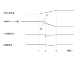
- FIG. 4 is a time chart showing an example of changes in the target oxygen storage amount, etc. due to the control of the above embodiment. From the top of the diagram, (a) intake air amount, (b) oxygen storage amount, (c) target air-fuel ratio, and (d) actual air-fuel ratio are shown. (b) In the oxygen storage amount column, the estimated oxygen storage amount b1 and the target oxygen storage amount b2 are shown superimposed.
- the amount of intake air is constant until time t1, and gradually increases from time t1 to t3.
- the estimated oxygen storage amount b1 and the target oxygen storage amount b2 in the oxygen storage amount column agree with each other until time t1.
- the target oxygen storage amount b2 tends to decrease and deviates from the estimated oxygen storage amount b1.
- the target air-fuel ratio changes to the rich side at time t2 as shown in column (c).
- the target air-fuel ratio is, for example, a constant value near the stoichiometric air-fuel ratio.
- the fuel injection amount is feedback-controlled in the increasing direction, and the actual air-fuel ratio shown in column (d) changes to the rich side. Therefore, the estimated oxygen storage amount b1 also gradually decreases.
- FIG. 4 is an explanatory time chart for explaining the behavior according to the above embodiment, and does not necessarily accurately depict the actual waveform. For example, in the period from time t1 to time t2, the delay due to the calculation cycle is exaggerated.
- the target oxygen storage amount of the three-way catalyst 15 is controlled based on the intake air amount, that is, the gas flow rate flowing into the three-way catalyst 15, and when the gas flow rate is large, the oxygen storage is relatively low. Controlled by quantity.
- the gas flow rate flowing into the three-way catalyst 15 is large, the flow rate of gas passing through the catalyst layer of the three-way catalyst 15 becomes high, and the slip rate of NOx tends to increase.
- the oxygen storage amount by controlling the oxygen storage amount to be relatively low, an increase in the slip rate of NOx due to an increase in the gas flow rate is offset, and NOx can be purified more reliably.
- the intake air amount is used as a parameter corresponding to the gas flow rate flowing into the three-way catalyst 15, but the exhaust gas flow rate is calculated based on the intake air amount and taking into account combustion.
- the flow rate of exhaust gas flowing through the exhaust passage may be detected by some means.
- the "intake air amount” may be either a mass flow rate or a volumetric flow rate.
Landscapes
- Engineering & Computer Science (AREA)
- Chemical & Material Sciences (AREA)
- Chemical Kinetics & Catalysis (AREA)
- Health & Medical Sciences (AREA)
- Toxicology (AREA)
- Combustion & Propulsion (AREA)
- Mechanical Engineering (AREA)
- General Engineering & Computer Science (AREA)
- Electrical Control Of Air Or Fuel Supplied To Internal-Combustion Engine (AREA)
- Exhaust Gas After Treatment (AREA)
Abstract
An exhaust passage (14) of an internal combustion engine (1) is provided with a three-way catalyst (15), and the air-fuel ratio is feedback controlled so as to maintain the oxygen storage amount in the three-way catalyst (15) at a target oxygen storage amount. An estimated oxygen storage amount (b1) is obtained from an intake air amount and an exhaust air-fuel ratio detected by an air-fuel ratio sensor (19), and a target air-fuel ratio is set in accordance with the difference between the target oxygen storage amount (b2) and the estimated oxygen storage amount (b1). The target oxygen storage amount (b2) is set with the characteristic of becoming lower as the intake air amount becomes higher, on the basis of the intake air amount corresponding to the flow rate of gas flowing into the three-way catalyst (15). The foregoing cancels out an increase in the NOx slip ratio when the gas flow rate is high.
Description
この発明は、内燃機関の排気通路に設けられる三元触媒の酸素ストレージ量を適切に制御する制御方法および装置に関する。
The present invention relates to a control method and apparatus for appropriately controlling the amount of oxygen storage in a three-way catalyst provided in an exhaust passage of an internal combustion engine.
三元触媒では排気中のCOならびにHCの酸化およびNOxの還元が可能であるが、触媒作用によるこれらの酸化と還元とを高いレベルで両立させるためには、触媒が酸素を吸蔵・放出する、いわゆる酸素ストレージ能力が重要である。そのため、三元触媒の酸素ストレージ量を監視し、この酸素ストレージ量が中間的な目標酸素ストレージ量(例えば50%等)を維持するように空燃比フィードバック制御における目標空燃比を可変制御する技術が知られている。
A three-way catalyst is capable of oxidizing CO and HC and reducing NOx in exhaust gas, but in order to achieve both oxidation and reduction at a high level through catalytic action, the catalyst must absorb and release oxygen. The so-called oxygen storage capacity is important. Therefore, there is a technology that monitors the oxygen storage amount of the three-way catalyst and variably controls the target air-fuel ratio in air-fuel ratio feedback control so that this oxygen storage amount maintains an intermediate target oxygen storage amount (for example, 50%, etc.). Are known.
さらに特許文献1には、内燃機関の負荷と回転速度とに基づき、NOxの排出量が多くなる運転条件では目標酸素ストレージ量を比較的小さくし、CO、HCの排出量が多くなる運転条件では目標酸素ストレージ量を比較的大きくする、ことが開示されている。
Further, Patent Document 1 states that, based on the load and rotational speed of the internal combustion engine, the target oxygen storage amount is set relatively small under operating conditions where the amount of NOx emissions increases, and under operating conditions where the amount of CO and HC emissions increases. It is disclosed that the target oxygen storage amount is relatively large.
本発明者の新たな知見によると、最適な目標酸素ストレージ量は三元触媒に流入するガス流量に相関する。三元触媒を流れるガス流量が大であると、三元触媒の触媒層を通過するガスの流速が高くなり、NOxのスリップ率(転化されずに通過してしまう割合)が増加する。従って、ガス流量が大であるほど三元触媒の酸素ストレージ量を低くすることが望ましい。
According to the new findings of the present inventors, the optimal target oxygen storage amount is correlated with the gas flow rate flowing into the three-way catalyst. When the gas flow rate through the three-way catalyst is large, the flow rate of the gas passing through the catalyst layer of the three-way catalyst becomes high, and the slip rate of NOx (the rate of NOx passing through without being converted) increases. Therefore, it is desirable to lower the oxygen storage amount of the three-way catalyst as the gas flow rate increases.
特許文献1には、このようなガス流量に関連した酸素ストレージ量の制御については開示がない。
Patent Document 1 does not disclose such control of the oxygen storage amount related to the gas flow rate.
この発明は、排気通路に三元触媒を備えた内燃機関の空燃比を理論空燃比付近の目標空燃比に沿うようにフィードバック制御するとともに、三元触媒の酸素ストレージ量が目標酸素ストレージ量となるように上記目標空燃比を制御する三元触媒の酸素ストレージ量制御方法において、
上記三元触媒に流入するガス流量に応じて、当該ガス流量が大であるほど目標酸素ストレージ量が小となるように、上記目標酸素ストレージ量を設定する。 This invention provides feedback control of the air-fuel ratio of an internal combustion engine equipped with a three-way catalyst in the exhaust passage so that it follows a target air-fuel ratio near the stoichiometric air-fuel ratio, and the oxygen storage amount of the three-way catalyst becomes the target oxygen storage amount. In the oxygen storage amount control method of a three-way catalyst for controlling the target air-fuel ratio,
The target oxygen storage amount is set in accordance with the gas flow rate flowing into the three-way catalyst such that the larger the gas flow rate, the smaller the target oxygen storage amount.
このように三元触媒に流入するガス流量が大であるほど目標酸素ストレージ量を低くすることで、ガス流速の上昇に起因したNOxのスリップ率の増加が相殺され、NOxのより確実な浄化が図れる。
In this way, by lowering the target oxygen storage amount as the gas flow rate flowing into the three-way catalyst increases, the increase in the NOx slip rate caused by the increase in gas flow rate is offset, and NOx purification is achieved more reliably. I can figure it out.
以下、この発明の一実施例を図面に基づいて詳細に説明する。図1は、この発明が適用される一実施例の内燃機関1の概略的な構成を示した説明図である。一実施例の内燃機関1は、4ストロークサイクルの火花点火式内燃機関(いわゆるガソリン機関)であって、各気筒に、吸気弁2ならびに排気弁3および点火プラグ4を備えている。また図示例は、筒内直接噴射式機関として構成されており、筒内に向けて燃料を噴射する燃料噴射弁5が、例えば吸気弁2側に配置されている。なお、吸気ポート6へ向けて燃料を噴射するポート噴射型の構成であってもよい。
Hereinafter, one embodiment of the present invention will be described in detail based on the drawings. FIG. 1 is an explanatory diagram showing a schematic configuration of an internal combustion engine 1 according to an embodiment to which the present invention is applied. An internal combustion engine 1 according to one embodiment is a four-stroke cycle spark ignition internal combustion engine (so-called gasoline engine), and each cylinder is provided with an intake valve 2, an exhaust valve 3, and a spark plug 4. Further, the illustrated example is configured as a cylinder direct injection type engine, and a fuel injection valve 5 that injects fuel into the cylinder is arranged, for example, on the intake valve 2 side. Note that a port injection type configuration in which fuel is injected toward the intake port 6 may be used.
各気筒の吸気ポート6に接続された吸気通路7のコレクタ部8上流側には、エンジンコントローラ9からの制御信号によって開度が制御される電子制御型スロットルバルブ10が介装されている。スロットルバルブ10の上流側に、吸入空気量を検出するエアフロメータ11が配設されており、さらに上流側に、エアクリーナ12が配設されている。
An electronically controlled throttle valve 10 whose opening degree is controlled by a control signal from an engine controller 9 is installed on the upstream side of the collector portion 8 of the intake passage 7 connected to the intake port 6 of each cylinder. An air flow meter 11 for detecting the amount of intake air is disposed upstream of the throttle valve 10, and an air cleaner 12 is disposed further upstream.
各気筒の排気ポート13は、1本の排気通路14として集合し、この排気通路14に、排気浄化のための三元触媒15が設けられている。三元触媒15は、例えば、微細な通路が形成されたモノリスセラミックス体の表面に触媒金属を含む触媒層をコーティングした、いわゆるモノリスセラミックス触媒である。なお、三元触媒15は、直列に配置された複数の触媒(例えば、マニホルド触媒と床下触媒)を含む構成であってもよい。
The exhaust ports 13 of each cylinder are combined into one exhaust passage 14, and this exhaust passage 14 is provided with a three-way catalyst 15 for purifying exhaust gas. The three-way catalyst 15 is, for example, a so-called monolithic ceramic catalyst in which a catalyst layer containing a catalyst metal is coated on the surface of a monolithic ceramic body in which fine passages are formed. Note that the three-way catalyst 15 may include a plurality of catalysts (for example, a manifold catalyst and an underfloor catalyst) arranged in series.
排気通路14の三元触媒15の入口側つまり該三元触媒15よりも上流側の位置には、排気空燃比を検出するための空燃比センサ19が配置されている。この空燃比センサ19は、排気空燃比に応じた出力が得られるいわゆる広域空燃比センサである。なお、空燃比センサ19を含む空燃比フィードバック制御系の較正や三元触媒15の劣化診断等のために三元触媒15の下流側に例えばO2センサ等からなる第2の空燃比センサを備えていてもよい。
An air-fuel ratio sensor 19 for detecting the exhaust air-fuel ratio is arranged in the exhaust passage 14 on the inlet side of the three-way catalyst 15, that is, at a position upstream of the three-way catalyst 15. This air-fuel ratio sensor 19 is a so-called wide-range air-fuel ratio sensor that can obtain an output according to the exhaust air-fuel ratio. Note that a second air-fuel ratio sensor, such as an O2 sensor, is provided downstream of the three-way catalyst 15 for calibrating the air-fuel ratio feedback control system including the air-fuel ratio sensor 19 and diagnosing deterioration of the three-way catalyst 15. It's okay.
空燃比センサ19やエアフロメータ11の検出信号は、エンジンコントローラ9に入力される。エンジンコントローラ9には、さらに、機関回転速度を検出するためのクランク角センサ21、冷却水温を検出する水温センサ22、運転者に操作されるアクセルペダルの踏込量を検出するアクセル開度センサ23、等の多数のセンサ類の検出信号が入力されている。エンジンコントローラ9は、これらの入力信号に基づき、燃料噴射弁5による燃料噴射量および噴射時期、点火プラグ4による点火時期、スロットルバルブ10の開度、等を最適に制御している。
Detection signals from the air-fuel ratio sensor 19 and the air flow meter 11 are input to the engine controller 9. The engine controller 9 further includes a crank angle sensor 21 for detecting the engine rotation speed, a water temperature sensor 22 for detecting the cooling water temperature, an accelerator opening sensor 23 for detecting the amount of depression of the accelerator pedal operated by the driver, Detection signals from a large number of sensors such as the following are input. Based on these input signals, the engine controller 9 optimally controls the fuel injection amount and injection timing by the fuel injection valve 5, the ignition timing by the spark plug 4, the opening degree of the throttle valve 10, etc.
エンジンコントローラ9は、内燃機関1の種々の制御の中の1つとして、三元触媒15による排気浄化性能を最適化するための空燃比制御を行う。空燃比制御は、空燃比センサ19が検出した排気空燃比に基づき、理論空燃比付近の目標空燃比に沿うようにフィードバック制御(例えばPID制御)によって燃料噴射量を制御するものである。ここで、目標空燃比は、排気空燃比から推定される三元触媒15の酸素ストレージ量が目標酸素ストレージ量となるように制御される。
As one of various controls of the internal combustion engine 1, the engine controller 9 performs air-fuel ratio control to optimize the exhaust purification performance of the three-way catalyst 15. The air-fuel ratio control is to control the fuel injection amount by feedback control (for example, PID control) based on the exhaust air-fuel ratio detected by the air-fuel ratio sensor 19 so as to follow a target air-fuel ratio near the stoichiometric air-fuel ratio. Here, the target air-fuel ratio is controlled so that the oxygen storage amount of the three-way catalyst 15 estimated from the exhaust air-fuel ratio becomes the target oxygen storage amount.
図2は、この酸素ストレージ量に基づく空燃比制御の流れをフローチャートに準じた形で示した説明図である。ステップS1,S2,S4として示す処理には、それぞれ、三元触媒15に流入するガス流量に相当するパラメータとして、エアフロメータ11が検出した吸入空気量が入力される。なお、「吸入空気量」は、気筒のサイクル当たりの空気量ではなく、内燃機関1に吸入される(つまりエアフロメータ11を通過する)単位時間当たりの空気の流量を意味している。また、ステップS1,S5として示す処理には、それぞれ空燃比センサ19が検出した排気空燃比(触媒入口空燃比)が入力される。ステップS1では、空燃比センサ19が検出した排気空燃比と三元触媒15に流入するガス流量つまり吸入空気量とに基づいて三元触媒15の酸素ストレージ量の推定を行う。これは、エンジンコントローラ9の演算サイクル毎にそのときの排気空燃比に基づく酸素ストレージ量の加減算を行うことで推定する。つまり、簡単に言えば、三元触媒15に流入する排気の排気空燃比がリーンであれば酸素ストレージ量が増え、リッチであれば酸素ストレージ量が減るので、正負の双方で積分していくことによって、その時点の酸素ストレージ量が推定される。以下では、これを「推定酸素ストレージ量」とする。
FIG. 2 is an explanatory diagram showing the flow of air-fuel ratio control based on this oxygen storage amount in a form similar to a flowchart. In the processes shown as steps S1, S2, and S4, the intake air amount detected by the air flow meter 11 is input as a parameter corresponding to the gas flow rate flowing into the three-way catalyst 15, respectively. Note that the "intake air amount" does not refer to the amount of air per cylinder cycle, but refers to the flow rate of air taken into the internal combustion engine 1 (that is, passing through the air flow meter 11) per unit time. Furthermore, the exhaust air-fuel ratio (catalyst inlet air-fuel ratio) detected by the air-fuel ratio sensor 19 is input to the processes shown as steps S1 and S5, respectively. In step S1, the oxygen storage amount of the three-way catalyst 15 is estimated based on the exhaust air-fuel ratio detected by the air-fuel ratio sensor 19 and the gas flow rate flowing into the three-way catalyst 15, that is, the amount of intake air. This is estimated by adding or subtracting the oxygen storage amount based on the exhaust air-fuel ratio at each calculation cycle of the engine controller 9. In other words, to put it simply, if the exhaust air-fuel ratio of the exhaust gas flowing into the three-way catalyst 15 is lean, the amount of oxygen storage increases, and if it is rich, the amount of oxygen storage decreases, so it is necessary to integrate both positive and negative. The amount of oxygen storage at that point in time is estimated. In the following, this will be referred to as "estimated oxygen storage amount."
ステップS2では、三元触媒15に流入するガス流量つまり吸入空気量に基づいて、目標酸素ストレージ量を設定する。図3は、吸入空気量に対する目標酸素ストレージ量の特性を示している。例えば、図3に示すような特性がテーブルの形でエンジンコントローラ9に与えられており、入力となる吸入空気量に対して目標酸素ストレージ量が出力される。図3に示すように、目標酸素ストレージ量は、吸入空気量が大となるほど小さな値となる特性を有する。より詳しくは、吸入空気量と目標酸素ストレージ量との間の相関関係として、吸入空気量が相対的に少ない領域では吸入空気量の増加に対する目標酸素ストレージ量の低下が急激であり、吸入空気量が相対的に多い領域(図3の右側の領域)では吸入空気量の増加に対する目標酸素ストレージ量の低下が緩やかな特性を有している。
In step S2, a target oxygen storage amount is set based on the gas flow rate flowing into the three-way catalyst 15, that is, the amount of intake air. FIG. 3 shows the characteristics of the target oxygen storage amount with respect to the intake air amount. For example, characteristics as shown in FIG. 3 are given to the engine controller 9 in the form of a table, and a target oxygen storage amount is output for an input intake air amount. As shown in FIG. 3, the target oxygen storage amount has a characteristic that the larger the intake air amount, the smaller the value. More specifically, the correlation between the intake air amount and the target oxygen storage amount is that in regions where the intake air amount is relatively small, the target oxygen storage amount decreases rapidly as the intake air amount increases; In the region where is relatively large (the region on the right side of FIG. 3), the target oxygen storage amount decreases gradually with respect to the increase in the intake air amount.
ステップS3においては、ステップS2で得られる目標酸素ストレージ量とステップS1で得られる推定酸素ストレージ量とを比較して、両者の差分を求める。
In step S3, the target oxygen storage amount obtained in step S2 and the estimated oxygen storage amount obtained in step S1 are compared to determine the difference between the two.
この差分の値は、ステップS4の処理の入力の一つとなる。ステップS4では、この差分の値と三元触媒15に流入するガス流量つまり吸入空気量とを用いて、目標空燃比(三元触媒15入口側での目標空燃比)を算出する。例えば推定酸素ストレージ量が目標酸素ストレージ量よりも大であれば、理論空燃比よりもリッチ側へ目標空燃比が制御される。三元触媒15に流入するガス流量が大であると、空燃比をリッチ化したことに伴う酸素ストレージ量の低下が相対的に急となるので、適当な速度で酸素ストレージ量が変化するように、ガス流量つまり吸入空気量を考慮して目標空燃比が設定される。
The value of this difference becomes one of the inputs for the process in step S4. In step S4, a target air-fuel ratio (target air-fuel ratio at the inlet side of the three-way catalyst 15) is calculated using the value of this difference and the gas flow rate flowing into the three-way catalyst 15, that is, the amount of intake air. For example, if the estimated oxygen storage amount is larger than the target oxygen storage amount, the target air-fuel ratio is controlled to be richer than the stoichiometric air-fuel ratio. If the gas flow rate flowing into the three-way catalyst 15 is large, the oxygen storage amount will decrease relatively rapidly due to enriching the air-fuel ratio, so the oxygen storage amount should be changed at an appropriate speed. The target air-fuel ratio is set in consideration of the gas flow rate, that is, the intake air amount.
ステップS5では、ステップS4で得られた目標空燃比と空燃比センサ19が検出した排気空燃比(つまり実空燃比)との差分を求め、例えばPID制御等のフィードバック制御によって、燃料噴射量のフィードバック補正量を出力する。最終的に、燃料噴射弁5から各サイクル毎に噴射される燃料噴射量が、このフィードバック補正量を用いて補正される。
In step S5, the difference between the target air-fuel ratio obtained in step S4 and the exhaust air-fuel ratio (that is, the actual air-fuel ratio) detected by the air-fuel ratio sensor 19 is determined, and the fuel injection amount is fed back by feedback control such as PID control. Output the correction amount. Finally, the amount of fuel injected from the fuel injection valve 5 in each cycle is corrected using this feedback correction amount.
図4は、上記実施例の制御による目標酸素ストレージ量等の変化の一例を示したタイムチャートである。図の上から順に、(a)吸入空気量、(b)酸素ストレージ量、(c)目標空燃比、(d)実空燃比、を示している。(b)酸素ストレージ量の欄には、推定酸素ストレージ量b1と、目標酸素ストレージ量b2と、が重ねて示してある。
FIG. 4 is a time chart showing an example of changes in the target oxygen storage amount, etc. due to the control of the above embodiment. From the top of the diagram, (a) intake air amount, (b) oxygen storage amount, (c) target air-fuel ratio, and (d) actual air-fuel ratio are shown. (b) In the oxygen storage amount column, the estimated oxygen storage amount b1 and the target oxygen storage amount b2 are shown superimposed.
このタイムチャートの例では、時間t1までは吸入空気量が一定であり、時間t1からt3までの間は、吸入空気量が徐々に増加する。酸素ストレージ量の欄における推定酸素ストレージ量b1と目標酸素ストレージ量b2とは、時間t1までは互いに一致している。時間t1において吸入空気量が増加し始めると、目標酸素ストレージ量b2が低下傾向となり、推定酸素ストレージ量b1から乖離する。
In the example of this time chart, the amount of intake air is constant until time t1, and gradually increases from time t1 to t3. The estimated oxygen storage amount b1 and the target oxygen storage amount b2 in the oxygen storage amount column agree with each other until time t1. When the intake air amount starts to increase at time t1, the target oxygen storage amount b2 tends to decrease and deviates from the estimated oxygen storage amount b1.
そのため、目標酸素ストレージ量b2と推定酸素ストレージ量b1との差分に基づき、時間t2において(c)欄に示すように目標空燃比がリッチ側へ変化する。時間t2までは、目標空燃比は例えば理論空燃比付近の一定値である。時間t2において目標空燃比がリッチ側へ変化することで、燃料噴射量が増加方向へフィードバック制御され、(d)欄に示す実空燃比がリッチ側へ変化する。従って、推定酸素ストレージ量b1も徐々に低下していく。
Therefore, based on the difference between the target oxygen storage amount b2 and the estimated oxygen storage amount b1, the target air-fuel ratio changes to the rich side at time t2 as shown in column (c). Until time t2, the target air-fuel ratio is, for example, a constant value near the stoichiometric air-fuel ratio. As the target air-fuel ratio changes to the rich side at time t2, the fuel injection amount is feedback-controlled in the increasing direction, and the actual air-fuel ratio shown in column (d) changes to the rich side. Therefore, the estimated oxygen storage amount b1 also gradually decreases.
なお、図4は、上記実施例による挙動を説明するための説明的なタイムチャートであり、必ずしも実際の波形を正しく描いたものではない。例えば、時間t1から時間t2までの期間は、演算サイクルによる遅れを誇張して描いている。
Note that FIG. 4 is an explanatory time chart for explaining the behavior according to the above embodiment, and does not necessarily accurately depict the actual waveform. For example, in the period from time t1 to time t2, the delay due to the calculation cycle is exaggerated.
上記実施例によれば、三元触媒15の目標酸素ストレージ量が吸入空気量つまり三元触媒15に流入するガス流量に基づいて制御され、ガス流量が大である場合に相対的に低い酸素ストレージ量に制御される。三元触媒15に流入するガス流量が大であると、三元触媒15の触媒層を通過するガスの流速が高くなり、NOxのスリップ率が増加傾向となる。上記実施例では、酸素ストレージ量が相対的に低く制御されることで、ガス流速の上昇に起因したNOxのスリップ率の増加が相殺され、NOxのより確実な浄化が図れる。
According to the above embodiment, the target oxygen storage amount of the three-way catalyst 15 is controlled based on the intake air amount, that is, the gas flow rate flowing into the three-way catalyst 15, and when the gas flow rate is large, the oxygen storage is relatively low. Controlled by quantity. When the gas flow rate flowing into the three-way catalyst 15 is large, the flow rate of gas passing through the catalyst layer of the three-way catalyst 15 becomes high, and the slip rate of NOx tends to increase. In the embodiment described above, by controlling the oxygen storage amount to be relatively low, an increase in the slip rate of NOx due to an increase in the gas flow rate is offset, and NOx can be purified more reliably.
以上、この発明の一実施例を説明したが、この発明は上記実施例に限定されるものではなく、種々の変更が可能である。例えば、上記実施例では、三元触媒15に流入するガス流量に相当するパラメータとして吸入空気量を用いているが、吸入空気量を基礎に燃焼を考慮して排気ガス流量を算出するようにしてもよく、あるいは、何らかの手段で排気通路を流れる排気ガス流量を検出するようにしてもよい。
Although one embodiment of this invention has been described above, this invention is not limited to the above embodiment, and various changes are possible. For example, in the above embodiment, the intake air amount is used as a parameter corresponding to the gas flow rate flowing into the three-way catalyst 15, but the exhaust gas flow rate is calculated based on the intake air amount and taking into account combustion. Alternatively, the flow rate of exhaust gas flowing through the exhaust passage may be detected by some means.
なお、上記実施例において「吸入空気量」は質量流量および体積流量のいずれであってもよく、例えば、図3に示したような目標酸素ストレージ量と吸入空気量との関係をそれぞれに適した形で設定すればよい。
In the above embodiment, the "intake air amount" may be either a mass flow rate or a volumetric flow rate. For example, the relationship between the target oxygen storage amount and the intake air amount as shown in FIG. You can set it in the form.
Claims (4)
- 排気通路に三元触媒を備えた内燃機関の空燃比を理論空燃比付近の目標空燃比に沿うようにフィードバック制御するとともに、三元触媒の酸素ストレージ量が目標酸素ストレージ量となるように上記目標空燃比を制御する三元触媒の酸素ストレージ量制御方法において、
上記三元触媒に流入するガス流量に応じて、当該ガス流量が大であるほど目標酸素ストレージ量が小となるように、上記目標酸素ストレージ量を設定する、
三元触媒の酸素ストレージ量制御方法。 The air-fuel ratio of an internal combustion engine equipped with a three-way catalyst in the exhaust passage is feedback-controlled so as to follow the target air-fuel ratio near the stoichiometric air-fuel ratio, and the oxygen storage amount of the three-way catalyst is controlled to match the target oxygen storage amount. In a method for controlling the amount of oxygen storage in a three-way catalyst that controls the air-fuel ratio,
Setting the target oxygen storage amount in accordance with the gas flow rate flowing into the three-way catalyst such that the larger the gas flow rate, the smaller the target oxygen storage amount;
A method for controlling the amount of oxygen storage in a three-way catalyst. - 上記ガス流量と上記目標酸素ストレージ量との間の相関関係として、ガス流量が相対的に少ない領域ではガス流量の増加に対する目標酸素ストレージ量の低下が急激であり、ガス流量が相対的に多い領域ではガス流量の増加に対する目標酸素ストレージ量の低下が緩やかな特性を有している、
請求項1に記載の三元触媒の酸素ストレージ量制御方法。 The correlation between the above gas flow rate and the above target oxygen storage amount is that in regions where the gas flow rate is relatively low, the target oxygen storage amount decreases rapidly with respect to an increase in the gas flow rate, and in regions where the gas flow rate is relatively high. In this case, the target oxygen storage amount decreases gradually as the gas flow rate increases.
The method for controlling the amount of oxygen storage in a three-way catalyst according to claim 1. - 内燃機関に吸入される空気の流量を上記ガス流量とみなす、
請求項1に記載の三元触媒の酸素ストレージ量制御方法。 The flow rate of air taken into the internal combustion engine is regarded as the above gas flow rate,
The method for controlling the amount of oxygen storage in a three-way catalyst according to claim 1. - 内燃機関の排気通路に設けられた三元触媒と、この三元触媒の入口側に設けられた空燃比センサと、燃料噴射量を制御するコントローラと、を備え、上記コントローラによって内燃機関の空燃比を理論空燃比付近の目標空燃比に沿うようにフィードバック制御するとともに、三元触媒の酸素ストレージ量が目標酸素ストレージ量となるように上記目標空燃比を制御する三元触媒の酸素ストレージ量制御装置において、
上記コントローラは、
上記三元触媒に流入するガス流量に応じて、当該ガス流量が大であるほど目標酸素ストレージ量が小となるように、上記目標酸素ストレージ量を設定する、
三元触媒の酸素ストレージ量制御装置。 The controller includes a three-way catalyst provided in the exhaust passage of the internal combustion engine, an air-fuel ratio sensor provided on the inlet side of the three-way catalyst, and a controller that controls the amount of fuel injection. A three-way catalyst oxygen storage amount control device that performs feedback control to follow a target air-fuel ratio near the stoichiometric air-fuel ratio, and controls the target air-fuel ratio so that the oxygen storage amount of the three-way catalyst becomes the target oxygen storage amount. In,
The above controller is
Setting the target oxygen storage amount in accordance with the gas flow rate flowing into the three-way catalyst such that the larger the gas flow rate, the smaller the target oxygen storage amount.
Three-way catalyst oxygen storage amount control device.
Priority Applications (1)
| Application Number | Priority Date | Filing Date | Title |
|---|---|---|---|
| PCT/JP2022/020843 WO2023223504A1 (en) | 2022-05-19 | 2022-05-19 | Device and method for controlling oxygen storage amount in three-way catalyst |
Applications Claiming Priority (1)
| Application Number | Priority Date | Filing Date | Title |
|---|---|---|---|
| PCT/JP2022/020843 WO2023223504A1 (en) | 2022-05-19 | 2022-05-19 | Device and method for controlling oxygen storage amount in three-way catalyst |
Publications (1)
| Publication Number | Publication Date |
|---|---|
| WO2023223504A1 true WO2023223504A1 (en) | 2023-11-23 |
Family
ID=88834931
Family Applications (1)
| Application Number | Title | Priority Date | Filing Date |
|---|---|---|---|
| PCT/JP2022/020843 WO2023223504A1 (en) | 2022-05-19 | 2022-05-19 | Device and method for controlling oxygen storage amount in three-way catalyst |
Country Status (1)
| Country | Link |
|---|---|
| WO (1) | WO2023223504A1 (en) |
Citations (3)
| Publication number | Priority date | Publication date | Assignee | Title |
|---|---|---|---|---|
| JP2008255973A (en) * | 2007-04-09 | 2008-10-23 | Mitsubishi Motors Corp | Exhaust emission control device for internal combustion engine |
| JP2010169020A (en) * | 2009-01-23 | 2010-08-05 | Nissan Motor Co Ltd | Exhaust emission control device |
| JP2015068224A (en) * | 2013-09-27 | 2015-04-13 | トヨタ自動車株式会社 | Control device for internal combustion engine |
-
2022
- 2022-05-19 WO PCT/JP2022/020843 patent/WO2023223504A1/en unknown
Patent Citations (3)
| Publication number | Priority date | Publication date | Assignee | Title |
|---|---|---|---|---|
| JP2008255973A (en) * | 2007-04-09 | 2008-10-23 | Mitsubishi Motors Corp | Exhaust emission control device for internal combustion engine |
| JP2010169020A (en) * | 2009-01-23 | 2010-08-05 | Nissan Motor Co Ltd | Exhaust emission control device |
| JP2015068224A (en) * | 2013-09-27 | 2015-04-13 | トヨタ自動車株式会社 | Control device for internal combustion engine |
Similar Documents
| Publication | Publication Date | Title |
|---|---|---|
| JP4314636B2 (en) | Air-fuel ratio control device for internal combustion engine | |
| JPWO2012059984A1 (en) | Control device for internal combustion engine | |
| JP2013204511A (en) | Control apparatus for internal combustion engine | |
| JP4943873B2 (en) | In-cylinder injection spark ignition internal combustion engine control device | |
| WO2023223504A1 (en) | Device and method for controlling oxygen storage amount in three-way catalyst | |
| JPH11107827A (en) | Catalyst temperature controller for internal combustion engine | |
| WO2024047839A1 (en) | Air–fuel ratio control method and device for internal combustion engine | |
| JP3991292B2 (en) | Exhaust purification device and exhaust purification method for internal combustion engine | |
| JPH06294342A (en) | Air-fuel ratio feedback controller of internal combustion engine | |
| JP4333264B2 (en) | Diesel engine control device | |
| JP4063743B2 (en) | Fuel injection timing control device for internal combustion engine | |
| JP3309776B2 (en) | Ignition timing control device for internal combustion engine | |
| JP3009228B2 (en) | Exhaust gas purification method and apparatus for natural gas engine | |
| WO2024004117A1 (en) | Method and device for controlling injection amount of cylinder direct injection-type spark ignition internal combustion engine | |
| JP5308875B2 (en) | Exhaust gas purification device for internal combustion engine | |
| JPH0633749A (en) | Secondary air control device for internal combustion engine | |
| JP3879342B2 (en) | Exhaust gas purification device for internal combustion engine | |
| JP2002122018A (en) | Catalyst-temperature estimating device | |
| JP3161248B2 (en) | Air-fuel ratio control device for internal combustion engine with EGR device | |
| JP2599941B2 (en) | Engine fuel control device | |
| JPH077568Y2 (en) | Engine controller | |
| JP2024005172A (en) | Method and device for controlling warming-up of three-way catalyst | |
| JP4075827B2 (en) | Engine exhaust purification system | |
| JPH0460135A (en) | Control device of engine | |
| JP2022059349A (en) | Controller of internal combustion engine |
Legal Events
| Date | Code | Title | Description |
|---|---|---|---|
| 121 | Ep: the epo has been informed by wipo that ep was designated in this application |
Ref document number: 22941873 Country of ref document: EP Kind code of ref document: A1 |