WO2023218523A1 - Second endoscopic system, first endoscopic system, and endoscopic inspection method - Google Patents
Second endoscopic system, first endoscopic system, and endoscopic inspection method Download PDFInfo
- Publication number
- WO2023218523A1 WO2023218523A1 PCT/JP2022/019794 JP2022019794W WO2023218523A1 WO 2023218523 A1 WO2023218523 A1 WO 2023218523A1 JP 2022019794 W JP2022019794 W JP 2022019794W WO 2023218523 A1 WO2023218523 A1 WO 2023218523A1
- Authority
- WO
- WIPO (PCT)
- Prior art keywords
- information
- endoscope system
- image
- operation unit
- unit
- Prior art date
Links
- 238000000034 method Methods 0.000 title claims abstract description 115
- 238000007689 inspection Methods 0.000 title abstract description 14
- 210000000056 organ Anatomy 0.000 claims abstract description 128
- 230000008859 change Effects 0.000 claims abstract description 75
- 230000008569 process Effects 0.000 claims abstract description 72
- 238000003384 imaging method Methods 0.000 claims description 84
- 238000003780 insertion Methods 0.000 claims description 46
- 230000037431 insertion Effects 0.000 claims description 46
- 238000005452 bending Methods 0.000 claims description 33
- 230000033001 locomotion Effects 0.000 claims description 18
- 238000001839 endoscopy Methods 0.000 claims description 14
- 210000003484 anatomy Anatomy 0.000 claims description 13
- XLYOFNOQVPJJNP-UHFFFAOYSA-N water Substances O XLYOFNOQVPJJNP-UHFFFAOYSA-N 0.000 claims description 12
- 210000004400 mucous membrane Anatomy 0.000 claims description 8
- 239000000049 pigment Substances 0.000 claims description 6
- 230000005484 gravity Effects 0.000 claims description 5
- 239000007788 liquid Substances 0.000 claims description 3
- 238000005507 spraying Methods 0.000 claims description 2
- 238000012545 processing Methods 0.000 description 47
- 238000004891 communication Methods 0.000 description 35
- 238000011282 treatment Methods 0.000 description 35
- 230000006870 function Effects 0.000 description 24
- 238000013473 artificial intelligence Methods 0.000 description 20
- 230000003902 lesion Effects 0.000 description 17
- 210000002784 stomach Anatomy 0.000 description 15
- 238000003745 diagnosis Methods 0.000 description 14
- 210000003238 esophagus Anatomy 0.000 description 13
- 210000001187 pylorus Anatomy 0.000 description 13
- 238000012360 testing method Methods 0.000 description 11
- 210000000214 mouth Anatomy 0.000 description 10
- 230000003287 optical effect Effects 0.000 description 9
- 238000013528 artificial neural network Methods 0.000 description 8
- 238000010586 diagram Methods 0.000 description 7
- 230000002496 gastric effect Effects 0.000 description 7
- 210000002318 cardia Anatomy 0.000 description 5
- 238000001514 detection method Methods 0.000 description 5
- 210000001198 duodenum Anatomy 0.000 description 5
- 238000005286 illumination Methods 0.000 description 5
- 238000002347 injection Methods 0.000 description 5
- 239000007924 injection Substances 0.000 description 5
- 230000013016 learning Effects 0.000 description 5
- 238000010801 machine learning Methods 0.000 description 5
- 210000002569 neuron Anatomy 0.000 description 5
- 210000001835 viscera Anatomy 0.000 description 5
- 210000001260 vocal cord Anatomy 0.000 description 5
- 230000005540 biological transmission Effects 0.000 description 4
- 210000001035 gastrointestinal tract Anatomy 0.000 description 4
- 210000003128 head Anatomy 0.000 description 4
- 208000037062 Polyps Diseases 0.000 description 3
- 230000009471 action Effects 0.000 description 3
- 230000008901 benefit Effects 0.000 description 3
- 238000013135 deep learning Methods 0.000 description 3
- 230000004044 response Effects 0.000 description 3
- 238000010186 staining Methods 0.000 description 3
- 210000003437 trachea Anatomy 0.000 description 3
- 238000012549 training Methods 0.000 description 3
- 238000002604 ultrasonography Methods 0.000 description 3
- 238000004140 cleaning Methods 0.000 description 2
- 230000002183 duodenal effect Effects 0.000 description 2
- 239000000284 extract Substances 0.000 description 2
- 238000000605 extraction Methods 0.000 description 2
- 238000010191 image analysis Methods 0.000 description 2
- 230000006872 improvement Effects 0.000 description 2
- 239000011159 matrix material Substances 0.000 description 2
- 239000000203 mixture Substances 0.000 description 2
- 210000003800 pharynx Anatomy 0.000 description 2
- 230000000306 recurrent effect Effects 0.000 description 2
- 239000000523 sample Substances 0.000 description 2
- 210000000813 small intestine Anatomy 0.000 description 2
- 238000001356 surgical procedure Methods 0.000 description 2
- RBTBFTRPCNLSDE-UHFFFAOYSA-N 3,7-bis(dimethylamino)phenothiazin-5-ium Chemical compound C1=CC(N(C)C)=CC2=[S+]C3=CC(N(C)C)=CC=C3N=C21 RBTBFTRPCNLSDE-UHFFFAOYSA-N 0.000 description 1
- 208000032544 Cicatrix Diseases 0.000 description 1
- 206010052804 Drug tolerance Diseases 0.000 description 1
- 235000000177 Indigofera tinctoria Nutrition 0.000 description 1
- 206010028980 Neoplasm Diseases 0.000 description 1
- 206010060862 Prostate cancer Diseases 0.000 description 1
- 208000000236 Prostatic Neoplasms Diseases 0.000 description 1
- 208000004680 Rectal Fistula Diseases 0.000 description 1
- 206010002156 anal fistula Diseases 0.000 description 1
- 238000004458 analytical method Methods 0.000 description 1
- 238000013459 approach Methods 0.000 description 1
- 210000000013 bile duct Anatomy 0.000 description 1
- 230000000903 blocking effect Effects 0.000 description 1
- 210000004556 brain Anatomy 0.000 description 1
- 238000004364 calculation method Methods 0.000 description 1
- 239000002775 capsule Substances 0.000 description 1
- 238000006243 chemical reaction Methods 0.000 description 1
- 239000003795 chemical substances by application Substances 0.000 description 1
- 238000004590 computer program Methods 0.000 description 1
- 238000004195 computer-aided diagnosis Methods 0.000 description 1
- 239000000470 constituent Substances 0.000 description 1
- 238000013527 convolutional neural network Methods 0.000 description 1
- 230000001186 cumulative effect Effects 0.000 description 1
- 230000004069 differentiation Effects 0.000 description 1
- 230000000694 effects Effects 0.000 description 1
- 238000005265 energy consumption Methods 0.000 description 1
- 210000000887 face Anatomy 0.000 description 1
- 210000000232 gallbladder Anatomy 0.000 description 1
- 230000026781 habituation Effects 0.000 description 1
- 230000036541 health Effects 0.000 description 1
- 229940097275 indigo Drugs 0.000 description 1
- KHLVKKOJDHCJMG-QDBORUFSSA-L indigo carmine Chemical compound [Na+].[Na+].N/1C2=CC=C(S([O-])(=O)=O)C=C2C(=O)C\1=C1/NC2=CC=C(S(=O)(=O)[O-])C=C2C1=O KHLVKKOJDHCJMG-QDBORUFSSA-L 0.000 description 1
- 229960003988 indigo carmine Drugs 0.000 description 1
- COHYTHOBJLSHDF-UHFFFAOYSA-N indigo powder Natural products N1C2=CC=CC=C2C(=O)C1=C1C(=O)C2=CC=CC=C2N1 COHYTHOBJLSHDF-UHFFFAOYSA-N 0.000 description 1
- 235000012738 indigotine Nutrition 0.000 description 1
- 239000004179 indigotine Substances 0.000 description 1
- 208000015181 infectious disease Diseases 0.000 description 1
- 230000001678 irradiating effect Effects 0.000 description 1
- 210000004185 liver Anatomy 0.000 description 1
- 238000007477 logistic regression Methods 0.000 description 1
- 210000003750 lower gastrointestinal tract Anatomy 0.000 description 1
- 230000003211 malignant effect Effects 0.000 description 1
- 230000003340 mental effect Effects 0.000 description 1
- 229960000907 methylthioninium chloride Drugs 0.000 description 1
- 210000003097 mucus Anatomy 0.000 description 1
- 210000003928 nasal cavity Anatomy 0.000 description 1
- 210000000496 pancreas Anatomy 0.000 description 1
- 210000000277 pancreatic duct Anatomy 0.000 description 1
- 238000003909 pattern recognition Methods 0.000 description 1
- 230000002093 peripheral effect Effects 0.000 description 1
- 238000003825 pressing Methods 0.000 description 1
- 238000013102 re-test Methods 0.000 description 1
- 230000011514 reflex Effects 0.000 description 1
- 231100000241 scar Toxicity 0.000 description 1
- 230000037387 scars Effects 0.000 description 1
- 238000012706 support-vector machine Methods 0.000 description 1
- 230000002123 temporal effect Effects 0.000 description 1
- 230000007704 transition Effects 0.000 description 1
- 210000002438 upper gastrointestinal tract Anatomy 0.000 description 1
Images


Classifications
-
- A—HUMAN NECESSITIES
- A61—MEDICAL OR VETERINARY SCIENCE; HYGIENE
- A61B—DIAGNOSIS; SURGERY; IDENTIFICATION
- A61B1/00—Instruments for performing medical examinations of the interior of cavities or tubes of the body by visual or photographical inspection, e.g. endoscopes; Illuminating arrangements therefor
- A61B1/04—Instruments for performing medical examinations of the interior of cavities or tubes of the body by visual or photographical inspection, e.g. endoscopes; Illuminating arrangements therefor combined with photographic or television appliances
- A61B1/045—Control thereof
Definitions
- the present invention provides a second endoscope system capable of acquiring time-series operation content information from a first endoscope system and performing operations for examination based on this operation content information. , a first endoscope system therefor, and an endoscope inspection method.
- Patent Document 1 describes, in performing dental treatment, an imaging unit that photographs the inside of the oral cavity of a patient to be treated, a storage unit that stores a plurality of product information and processing procedure information for each application of each product, and a photographed image. a photographed image analysis section that detects the treatment target in the image and identifies the treatment steps; a processing procedure control section that selects the processing procedure corresponding to the treatment step; and a display control section that displays the processing procedure and the photographed images side by side. , a dental treatment support device is disclosed.
- Patent Document 1 describes displaying the processing procedure during treatment, and the dentist or the like can perform the treatment according to the displayed processing procedure.
- the target area for treatment can be easily found.
- the present invention has been made in view of the above circumstances, and provides a second endoscope system, a first endoscope system, and an endoscope system that allows easy access to target areas such as affected areas.
- the purpose is to provide a mirror inspection method.
- a second endoscope system provides an observation method for a subject who has undergone an organ examination using the first endoscope system.
- a second endoscope system for observing a target organ an acquisition unit that acquires time-series operation content information in the first endoscope system as operation unit information; an insertion operation determination unit that estimates an operation process when undergoing an examination using the second endoscope system, and compares the operation process estimated by the insertion operation determination unit with the operation unit information, and an operation guide unit that outputs operation guide information for operating the second endoscope system in order to observe a characteristic site in the target organ with the second endoscope system;
- the operation unit information is image change information estimated using the asymmetry of the organ to be observed.
- a second endoscope system is characterized in that, in the first invention, the asymmetry information of the organ to be observed is determined based on the anatomical positional relationship of a plurality of parts within the specific organ. .
- the operation unit information is information regarding an operation that continues for a predetermined period of time.
- a second endoscope system is the third invention, wherein the operation unit information is information regarding an operation start image and operations from the start to the end of the operation.
- a second endoscope system is characterized in that, in the first invention, the operation guide information outputted by the operation guide section identifies the characteristic part of the observation target organ. This is guide information for observing under observation conditions similar to those of the endoscopy system.
- the operation unit information is image change information indicating a series of the same operations.
- a second endoscope system in the first invention, determines the first direction when detecting asymmetry of the organ to be observed.
- a second endoscope system according to an eighth invention in the first invention, detects the asymmetry of the organ to be observed by detecting the direction in which the liquid accumulates, which is determined by the direction of gravity, or the already detected internal structure. Refers to the direction determined by the positional relationship.
- a second endoscope system according to a ninth invention is a second endoscope system according to the first invention, wherein the operation unit information reflects an angle at which a lever or a knob for rotating a distal end portion of the endoscope system is turned. to be determined.
- a second endoscope system according to a tenth invention is characterized in that in the first invention, the operation unit information is information whose operation unit is a process until the observation direction of the distal end of the endoscope system changes. be.
- a second endoscope system according to an eleventh invention is a second endoscope system according to the tenth invention, in which the observation direction of the distal end of the endoscope system is determined by twisting the endoscope system or by It changes by angulating the mirror system or by pushing the endoscopic system into the body.
- the operation unit information is information in which the unit of operation is a process until the shape of the organ to be observed changes.
- a second endoscope system according to a thirteenth invention is a second endoscope system according to the twelfth invention, wherein the operation unit information is obtained by air supply, water supply, and/or suction using the endoscope system. , or the process by which the shape of an organ is estimated to change by pushing the endoscope system into it is information whose operation unit is the process of changing the shape of an estimated organ.
- a second endoscope system according to a fourteenth invention is a second endoscope system according to the twelfth invention, in which the operation unit information includes dispersing a pigment and/or a stain using the first endoscope system. This is information whose operation unit is a process until the state of the mucous membrane of an organ is estimated to change by performing water supply by using the first endoscope system or by using the first endoscope system.
- a second endoscope system in the first invention, includes an operation guide for operating the second endoscope system to observe a characteristic site in the organ to be observed.
- the information is determined by comparing a plurality of pieces of operation unit information, and if the overlapping parts do not require follow-up observation, the corresponding The information is corrected and compared to the operation unit information excluding the operations of the duplicate parts.
- a second endoscope system according to a sixteenth invention, in the first invention, performs observation of a characteristic part of the observation target organ in the same manner as the first endoscope system, based on the operation unit information. Observe by automatic operation under certain conditions.
- the endoscopic examination method provides an endoscopic examination method for examining a subject using a second endoscope system for examining an organ using a first endoscope system.
- time-series operation content information in the first endoscope system is acquired as operation unit information
- the second The operation process when undergoing an examination using the endoscope system is estimated, the estimated operation process is compared with the operation unit information, and the characteristic parts of the organ to be observed are detected using the second endoscope system.
- Operation guide information for operating the second endoscope system for observation is output, and the operation unit information is image change information estimated using the asymmetry of the observation target organ.
- the first endoscope system includes an input unit for inputting images of organs of a subject in chronological order, and an input unit for dividing images of the organs obtained in chronological order into operation units, an operation unit determination unit that determines the operation performed for each unit; and a recording unit that records information regarding the image and endoscope operation in the operation unit as operation unit information for each operation unit determined by the operation unit determination unit. and an output section that outputs the operation unit information recorded in the recording section.
- the operation unit determination unit determines the distal end of the first endoscope based on the image acquired by the imaging unit. The operation is divided into the above operation units based on whether at least one of the insertion direction, rotation direction, and bending direction has changed. In the first endoscope system according to a twentieth invention, in the eighteenth invention, the operation unit determination unit determines the operation based on the asymmetry of the anatomical structure with respect to the image acquired by the imaging unit. Determine the direction of.
- the recording unit records a start image and an end image among the continuous images belonging to the operation unit, and Record the operation information indicating the operation status in.
- the recording section records operation information after a target object serving as a landmark near the target is discovered.
- the endoscopy method acquires images of organs of a subject in chronological order, divides the images of the organs acquired in chronological order into operation units, and performs a first operation for each operation unit.
- the operation performed by the endoscope is determined, and for each determined operation unit, the image and information regarding the endoscope operation in the operation unit are recorded in the recording unit as operation unit information, and the information recorded in the recording unit is recorded. Output the above operation unit information.
- the second endoscope system according to the twenty-fourth invention provides a second endoscope system for observing the organs of a subject who has undergone an organ examination using the first endoscope system.
- the endoscope system includes an input section for inputting recorded operation unit information for a subject who has been examined using the first endoscope system, and an input section for inputting recorded operation unit information, and an input section for inputting images of the subject's organs in chronological order. divides the above-mentioned images acquired in chronological order into operation units, estimates the operation state of the second endoscope system for each operation unit, and compares the estimated operation state with the above-mentioned operation. and an operation guide unit that compares the unit information and outputs guide information for observation under the same observation conditions as the first endoscope system.
- the program according to the twenty-fifth invention is configured to provide an organ to be observed using a second endoscope system for a subject who has had an organ examined using a first endoscope system.
- the observation computer obtains time-series operation content information in the first endoscope system as operation unit information, and performs an examination on the subject using the second endoscope system. estimating the operation process when undergoing the operation, comparing the estimated operation process with the operation unit information, and observing the characteristic parts of the observation target organ under the same observation conditions as the first endoscope system.
- the program according to the twenty-sixth invention acquires images of organs of a subject in chronological order, divides the images of the organs acquired in chronological order into operation units, and sets a first endoscope for each operation unit. For each determined operation unit, the image and information regarding the endoscope operation in the operation unit are recorded in a recording unit as operation unit information, and the operation unit information recorded in the recording unit is recorded. Output something, make a computer do something.
- a second endoscope system it is possible to provide a second endoscope system, a first endoscope system, and an endoscopy method that allow easy access to a target site such as an affected area.
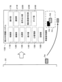
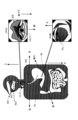
- FIG. 1 is a block diagram mainly showing the electrical configuration of an endoscope system according to an embodiment of the present invention.
- 1 is a block diagram mainly showing the electrical configuration of an endoscope system according to an embodiment of the present invention.
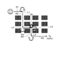
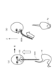
- FIG. 3 is a diagram illustrating an example of a route taken to reach an object serving as a landmark such as an affected area in an endoscope system according to an embodiment of the present invention.
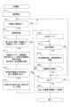
- the endoscope system according to one embodiment of the present invention it is a flowchart showing the operation in the first endoscope system.
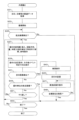
- the endoscope system according to one embodiment of the present invention it is a flowchart showing the operation in the second endoscope system.
- FIG. 3 is a diagram showing a process of inserting an endoscope in an endoscope system according to an embodiment of the present invention.
- FIG. 3 is a diagram showing a process of inserting an endoscope in an endoscope system according to an embodiment of the present invention.
- FIG. 2 is a diagram showing an example of a captured image when an endoscope is inserted in an endoscope system according to an embodiment of the present invention.
- FIG. 2 is a diagram showing an example of a captured image when an endoscope is inserted in an endoscope system according to an embodiment of the present invention.
- This endoscope system is ideal for examinations, examinations, and treatments by endoscopists (in this specification, examinations, examinations, and treatments may be collectively referred to as examinations or examinations, etc.), and reproduces examinations, etc.
- examinations or examinations, etc. examinations or examinations, etc.
- reproduces examinations, etc. We are making it possible to record and communicate information that can help. Furthermore, in order to reproduce the examination performed by an endoscopist, images during the examination are recorded and image changes and image characteristics are utilized.
- the operating state of the endoscopist is determined based on the following image changes. (1) If the change pattern of the inspection image is constant (for example, an image of driving through a tunnel), it is determined that the endoscope is moving straight; (2) the change pattern is unusual. If the rotation or twist is applied to the endoscope, it is determined that the endoscope has been rotated or twisted.
- up, down, left, and right are defined using the structure of the organ to be observed with the endoscope (for example, when viewed from the endoscope, the throat The vocal cord side is lower; in the stomach, the gastric angle side is upper).
- the position (direction) in an endoscopic image is displayed using the anatomical normal position (the anatomical normal position will be described later using FIG. 5). Using these clues, even non-endoscopy specialists can reproduce ideal examinations.
- Tg is a target site such as an affected area discovered by a specialist, and a non-specialist operates the endoscope so as to reach this target site Tg.
- Ob is an object that serves as a landmark on the route to reach the target site Tg. When this landmark Ob is found, the target region Tg is searched for using this landmark Ob as a clue. Although only one target region is depicted in FIG. 2, there may be a plurality of target regions.
- a specialist operates the first endoscope system, advances straight along route R1, and bends the endoscope at position L1. Change the direction of travel by rotating or rotating the vehicle. Thereafter, the endoscope is further advanced along route R2, and at position L2, the endoscope is bent or rotated to change the direction of travel to route R3. Proceeding in this state, the image of the landmark Ob is captured at position L3, the route is changed to route R4 at position L4, and the target area Tg, such as the affected area, is finally discovered.
- one operation unit is from the start of operation to position L1 along route R1
- one operation unit is from position L1 to position L2 along route R2
- one operation unit is from position L2 to position L2 along route R2.
- One operation unit is from position L3 to position L4 along route R4, and one operation unit is from position L4 to target region Tg along route R5. It is a unit of operation.
- the explanation is given by vertical and horizontal movement in two dimensions. However, since the object actually moves within a three-dimensional structure, operations involving rotation of the screen and operations that change the viewing position vertically and horizontally can also be assumed.
- an operating guide (operating advice) can be generated based on this information.
- a non-specialist can easily reach the target site Tg by operating the second endoscope system while receiving an operating guide.
- the second endoscope system uses the second endoscope system to perform an examination on the same patient (subject) on whom a specialist has performed an examination, by receiving the operation guide, the The target region Tg shown can be easily reached.
- operation guide information such as rotation and bending is displayed, and from then on, position L2 is displayed.
- position L3 position of landmark Ob
- position L4 position of landmark Ob
- Reference guide information is also displayed at locations other than this.
- the anatomical normal position is used to display the direction in the image. conduct.
- the specialist when looking at the lesser curvature side after insertion into the stomach, there are cases where the patient first looks at the greater curvature side from the cardia and then goes to the lesser curvature. If the final follow-up observation is on the lesser curvature side, the specialist (expert) will omit the part seen in the greater curvature, and only enter from the cardia and turn toward the lesser curvature (i.e., from the insertion of the cardia to the greater curvature). The operation of swinging back to the cardia and returning to the vicinity of the cardia insertion is omitted) may be recorded as a unit of operation.
- Operation unit information that remains as a history is included in the history if a specific guide starting point can be reset, such as ⁇ go forward and then go back'' or ⁇ look to the right and then look to the left.'' A plurality of pieces of operation unit information may be corrected to generate guide operation unit information in which the guide start point is reset, and this operation unit information may be referred to for guidance.
- this operation unit information may be referred to for guidance.
- the operation unit information may be corrected and compared.
- the operation unit information for the guide may be strictly corrected to create new data corresponding to the operation unit information for comparison, or the guide may be issued in anticipation without going to the trouble of creating new data.
- FIG. 5 A method for displaying directions within an image based on this anatomical orientation will be explained using FIG. 5.
- the tip of the endoscope is cylindrical, and the imaging unit is placed inside it, and images of the inside of the digestive tract, which has a complicated shape, are captured in either direction, upward or downward, or to the right. It's hard to tell if it's to the left.
- images of the inside of the digestive tract which has a complicated shape, are captured in either direction, upward or downward, or to the right. It's hard to tell if it's to the left.
- in general landscape photographs, portrait photographs, etc. it is possible to understand from the image which side of the screen is upward or downward, or whether it is forward or backward, whereas the digestive tract, etc. It is difficult to determine the direction from an image of the interior, and some definition is needed to represent the direction.
- Anatomical position is used to represent the direction.
- Anatomical upright position is a posture in which you stand straight with your palms facing forward (the direction your face is facing), and directions are expressed based on anatomical upright position. This premise is especially useful when expressing parts that easily change direction, such as limbs. However, even if anatomical orientation is assumed, representations of the directions of limbs, brains, etc. tend to cause confusion, so easy-to-understand representations as described below are preferred.
- the direction of the head is superior (superior) and the direction of feet is inferior (inferior).
- left and right are expressed as left and right as seen from the person being observed. That is, when a doctor is facing a patient, the left half of the patient's body is on the right side as viewed from the doctor. If a doctor is observing a patient's back, the right side of the patient's body is on the right side as seen from the doctor.
- the side facing the face is the front (anterior)
- the side facing the back is the back (posterior).
- Figure 5 shows the anatomical direction according to the normal position. Note that when gastric endoscopy is performed, the whole body is actually turned sideways (left lateral position), but in Figure 5, for convenience of drawing, the head is turned sideways (left side) and the head is turned sideways (left lateral position). The lower part of the neck is drawn facing forward.
- the insertion route Ro of the endoscope is shown by a broken line. The distal end of the endoscope is inserted from the oral cavity OC (depending on the model of the endoscope, it may be inserted from the nasal cavity NC), passes through the esophagus ES, and advances to the stomach St.
- Image P5A in FIG. 5 is an image before entering the esophagus ES when the distal end of the endoscope is inserted from the oral cavity OC.
- the vocal cords VC and the trachea Tr are on the lower side in the anatomically normal position, and the trachea Tr is on the front side, and the esophagus ES is on the upper side of the screen and on the back side in the anatomically normal position.
- FIG. 5 when the distal end of the endoscope advances in the direction of the duodenum, it advances toward the pylorus Py.
- the distal end of the endoscope may be advanced along the wall surface of the stomach St, and the endoscope may be turned in a direction in which the pylorus Py can be seen.
- Image P5B shown in FIG. 5 is an image of the pylorus Py viewed from the side. When this image P5B is visible, it is sufficient to perform a bending operation on the tip of the endoscope to change the direction of the tip.
- a specialist operates the first endoscope system 10A and records information until reaching the target site Tg such as an affected area, and a non-specialist performs an examination on the same subject.
- operation guide information is displayed based on the recorded information.
- FIG. 6 shows how the endoscope EDS is inserted from the oral cavity OC of the subject, passes through the stomach St of the subject, and inspects the pylorus Py. Note that in FIG. 6(a), similarly to FIG. 5, for convenience of drawing, the head is drawn sideways (facing the left), and the lower part of the neck is drawn forward.
- FIG. 6(a) shows the endoscope EDS being inserted into the oral cavity OC
- FIG. 6(b) shows the endoscope EDS being inserted into the esophagus ES and stomach St.
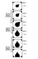
- FIG. 7 shows images P6a to P6f acquired when the endoscope EDS is inserted into the digestive tract, and these images change from moment to moment.
- Images P6a to P6c show the endoscope EDS being inserted into the esophagus ES at times T1 to T3, and at this time, the tip of the endoscope EDS is rotated or bent. It's not done and it's going straight. For this reason, the oval shape (hole shape) of the esophagus ES gradually becomes larger.
- Images P6a to P6c are images in the first operation unit.
- the endoscope EDS is rotated, and in the image acquired at this time, the elliptical (hole-shaped) protrusion portion is rotated.
- Images P6c to P6d are images in the second operation unit.
- the reason why the distal end of the endoscope EDS rotates from time T3 to time T4 is to search for the pylorus Py in the stomach St. That is, when the distal end of the endoscope EDS moves downward a predetermined distance along the wall surface of the stomach St, it reaches the vicinity of the pylorus Py, so at this timing, the distal end of the endoscope EDS is rotated. Find Pylorus Py. If the pylorus Py is found, it can be advanced to the duodenum.
- images P6e to P6f are images of the third operation unit.
- the operation unit information is image change information indicating a succession of the same motions estimated using the asymmetry of the observed organ.
- the operation unit information is image change information indicating a succession of the same motions estimated using the asymmetry of the observed organ.
- FIG. 7 shows the case where each of the straight operation, rotation operation, and bending operation is performed independently.
- multiple operations may be performed in a complex manner, and even in this case, by taking advantage of the asymmetry of internal organs, they can be broken down into individual operations. , just obtain the operation information.
- endoscopes will be developed that can perform bending operations other than the tip, as well as endoscopes that can bend in directions other than up, down, left, and right, and that will have functions similar to zoom lenses and will be able to control the tip toward and away from the tip.
- this embodiment can be applied in the same way in that case as well.
- the operation unit information does not need to be limited to operations related to changes in the observation position of the endoscope tip.
- the following operations are frequently performed when observing a target region using an endoscope system, and should be considered as a unit of operation. For example, by dispersing a pigment or stain, the shape of irregularities in the target region and the difference between a lesion and a normal region may be clearly visible.
- Visibility may also be improved by supplying water (for cleaning mucus, etc.) using an endoscope system.
- the estimated state of the mucous membrane of an organ may change due to active actions other than changing the position, and it is also important to use the process until the state of the mucous membrane of the organ changes as a unit of operation.
- the operation unit information is image information indicating a series of the same operations.
- the same action is simply inserting this amount, twisting and rotating this much, turning the knob this much to bend the tip (in Figure 7, "insertion direction, rotation, bending the tip”), etc.
- the "same operations" are classified in too short a period of time, the operation instructions may become too fragmented and difficult to understand.
- the guide becomes uneasy during the operation.
- the same operation be divided into periods of time (for example, from several seconds to several tens of seconds) that can be easily operated by the operator of the second endoscope system while referring to the guide.
- experienced experts can twist the device while inserting it, so it may be helpful to guide them in an easy-to-understand manner.
- the guide may be divided into two components, insertion and twisting, in a time-sharing manner.
- FIG. 6 shows the route for inserting the endoscope EDS from the oral cavity OC toward the pylorus Py.
- FIG. 8 shows an example of an image acquired by the endoscope EDS during this insertion.
- Image P11 is an image when the vocal cords VC are viewed from above
- image P12 is an image when the esophagus ES is viewed from above.
- Image P13 is an image when entering the stomach St
- image P14 is an image when the pylorus Py is viewed from above
- image P15 is an image when the pylorus Py is viewed from the side.
- internal organs are not symmetrical but asymmetrical, and by utilizing this asymmetry, the transition of operation during continuous motion can be estimated and the break in operation is taken as a unit. The unit of operation can be determined.
- operation unit information is recorded for each operation unit (for example, 1A, operation unit information 35b, see S11 in FIG. 3).
- This operation unit information can be said to be image change information indicating a succession of the same motions estimated using the asymmetry of the observed organ (for example, see FIG. 7).
- the asymmetry information of the organ to be observed is determined based on the anatomical positional relationship of a plurality of parts within the specific organ. It may be adapted to match the anatomical orientation representation.
- the operation unit information is information regarding an operation that continues for a predetermined period of time.
- the operation unit information may be information regarding an operation start image and operations from the start to the end of the operation.
- the operation unit information may include an end image, and/or information serving as a landmark for discovering the target region, and/or information regarding the target region, and/or pre-discovery operation information (for example, in FIG. (See S41, S48).
- the operation unit information may be determined by reflecting the angle at which a lever or knob for rotating the distal end of the endoscope system is turned. Further, the operation unit information may be information in which the operation unit is a process until the observation direction of the distal end of the endoscope system changes. The viewing direction of the distal end of the endoscopic system may be changed by twisting the endoscopic system, by angling the endoscopic system, or by pushing the endoscopic system into the body. .
- the operation unit information may be information in which the operation unit is a process until the shape of the organ to be observed changes.
- Operation unit information is information in which the operation unit is the process of changing the shape of an estimated organ by supplying air, water, or suction using an endoscope system, or by pushing the endoscope system. It may be.
- the operation unit information is estimated by spraying a pigment/staining agent using the first endoscope system or by delivering water (for mucous membrane cleaning) using the first endoscope system. This information is based on the process of changing the state of the mucous membrane of the organ being treated as a unit of operation.
- the operation unit information is not limited to operations related to changes in the observation position of the tip of the endoscope, but also changes in the observation state, visibility, etc. by changing the state of the target part or something blocking it during observation with the endoscope. Operations that improve detectability may also be included in the operation unit information.
- the anatomical normal position is used to represent the direction. Therefore, the first direction may be determined when detecting the asymmetry of the organ to be observed. Furthermore, in detecting the asymmetry of the organ to be observed, reference may be made to the direction in which liquid accumulates, which is determined by the direction of gravity, or the direction determined by the positional relationship of already detected structures within the body.
- the present invention is not limited to this, and characteristic parts of the observation target organ may be observed by automatic operation under the same observation conditions as the first endoscope system based on the operation unit information.
- the characteristic parts of the organ to be observed are Guide information is output so that observation can be performed under the same observation conditions as the endoscope system No. 1 (for example, see S37 and S47 in FIG. 4).
- similar observation conditions include the size of the object photographed within the screen, the angle of view, etc., and the positional relationship between the imaging unit and the observation object when observing the observation object is the same. This is the condition for making it.
- FIGS. 1A and 1B This endoscope system provides information on the organs to be observed by a subject (including a patient) who has undergone an organ examination (including diagnosis and treatment) using the first endoscope system. and a second endoscope system for observing.
- the endoscope system according to this embodiment includes an endoscope system 10A, an auxiliary device 30 provided in a hospital system server, etc., and a second endoscope system 10B.
- the endoscope system 10A and the second endoscope system 10B are endoscopes that are inserted from the oral cavity through the esophagus to examine the stomach or duodenum.
- the endoscope system 10A is an endoscope used for the first examination of the subject
- the second endoscope system 10B is an endoscope used for the second and subsequent examinations of the subject. explain.
- the endoscope system 10A and the second endoscope system 10B may be the same model of endoscope, but will be described here as different models.
- the second endoscope system 10B is the same model as the endoscope system 10A, it may be the same device or may be a different model/device.
- changes in the patient's physical and health conditions such as changes in the patient's affected area, physical and mental constraints such as changes in doctors, fatigue and habituation, or changes in availability, assistants, peripheral equipment, environment, etc.
- the results may not be exactly the same due to changes in surrounding conditions (including surrounding circumstances). Therefore, in this embodiment, information can be inherited when multiple tests are performed at different timings (in many cases, the test dates are different, but same-day retests can be assumed). It would be good if you could.
- the endoscope system 10A is used by a doctor to observe the inside of the pharynx, esophagus, stomach, and duodenum, and perform tests, treatments, surgeries, etc.
- This endoscope system 10A includes a control section 11A, an imaging section 12A, a light source section 13A, a display section 14A, an ID management section 15A, a recording section 16A, an operation section 17A, an inference engine 18A, a clock section 20A, and a communication section 21A. are doing.
- each of the above-mentioned parts may be provided in an integrated device, but may also be distributed and arranged in a plurality of devices.
- the control unit 11A is composed of one or more processors having a processing device such as a CPU (Central Processing Unit), a memory storing a program (the program may be stored in the recording unit 16A), etc., and executes the program. and controls each part within the endoscope system 10A.
- the CPU of the control unit 11A executes the program in cooperation with the CPU of the control unit 31 of the auxiliary device 30, and realizes the flow operation shown in FIG.
- the control unit 11A performs various controls when the endoscope system 10A performs an endoscopic examination of a subject (patient), and also transmits image data P1 acquired during the examination to an in-hospital system, a server, etc. Control is performed to transmit data to the auxiliary device 30 located there.
- the imaging unit 12A is provided at the distal end of the endoscope system 10A that is inserted into the body, and includes an optical lens, an image sensor, an imaging circuit, an image processing circuit, and the like.
- the imaging unit 12A is assumed to be composed of a small-sized imaging device and an imaging optical system that forms an image of the object on the imaging device, and specifications such as the focus position and the focal length of the optical lens are determined. Further, the imaging unit 12A may be provided with an autofocus function or an expanded depth of field function (EDOF function), and in this case, it is possible to determine the distance to the object, the size of the object, and the like. If the imaging unit 12A has an angle of view of approximately 140 degrees to 170 degrees, it is possible to photograph over a wide range.
- EEOF function expanded depth of field function
- the imaging optical system may include a zoom lens.
- the imaging unit 12A acquires image data of a moving image at predetermined time intervals determined by the frame rate, performs image processing on this image data, and then records it in the recording unit 16A. Furthermore, when the release button in the operating section 17A is operated, the imaging section 12A acquires still image data, and this still image data is recorded in the recording section 16A.
- the imaging unit 12A functions as an imaging unit that acquires images of the subject's organs in time series (for example, see S1 in FIG. 3).
- the image P1 is an image acquired by the imaging unit 12A, and is transmitted to the input unit 32 of the auxiliary device 30 through the communication unit 21A.
- Image P1 is a time series image
- image P11 is an image acquired immediately after inserting the tip of endoscope system 10A into the oral cavity
- image P20 is acquired immediately before removing endoscope system 10A from the oral cavity. It is an image.
- Images P11 to P16 are consecutive images belonging to the operation unit.
- images P15 to P19 are also images belonging to another operation unit.
- the unit of operation is the number of steps required to change the image pattern by changing the insertion direction, rotating the tip, bending the tip, etc., until the specialist reaches the target area such as the affected area. This is a series of images.
- images P11 to P16 are the first unit of operation
- images P15 to P19 are the second unit of operation.
- images P15 and P16 overlap in the first and second operation units.
- images do not need to overlap between the two operation units, and images between the two operation units do not need to belong to the operation unit (in the latter case, the operation is not performed).
- the light source section 13A includes a light source, a light source control section, and the like.
- the light source section 13A illuminates the object with appropriate brightness.
- a light source is placed at the distal end of the endoscope system 10A to illuminate the inside of the body, such as an affected area, and a light source control unit controls the illumination by the light source.
- a light source control unit controls the illumination by the light source.
- the display unit 14A displays an image inside the body based on the image data acquired by the imaging unit 12A. Further, the display unit 14A can display an operation guide superimposed on the inspection image. For example, a display indicating the vicinity of the site (affected area) is made. This operation guide may be displayed based on the inference result by the inference engine 18A. Furthermore, a menu screen for operating and displaying the endoscope system 10A can also be displayed.
- the ID management unit 15A performs ID management for identifying a subject (patient) when a specialist performs an examination using the endoscope system 10A. For example, a specialist may input the ID of the subject (patient) through the operation unit 17A of the endoscope system 10A. Further, the ID management unit 15A may associate an ID with the image data acquired by the imaging unit 12A.
- the recording unit 16A has an electrically rewritable nonvolatile memory, and records adjustment values for operating the endoscope system 10A, programs used in the control unit 11A, and the like. It also records image data acquired by the imaging unit 12A.
- the operation unit 17A is an operation unit (also referred to as an interface) for bending the distal end of the endoscope system 10A in an arbitrary direction, a light source operation unit, an operation unit for image capturing, a treatment instrument, etc. It has various operation parts such as an operation part.
- the ID of the subject (patient) may be input through the operation unit 17A.
- the inference model is placed within the inference engine 18A.
- This inference model can be used in various ways, such as an inference model that infers possible diseased areas such as tumors or polyps in images acquired by the imaging unit 12A, and an operation guide for operating the endoscope system 10A. It may be composed of an inference model.
- the inference engine 18A may be configured by hardware, software (program), or a combination of hardware and software.
- the clock section 20A has a calendar function and a timekeeping function.
- image data is acquired by the imaging unit 12A, the acquisition date and time may be output, or the elapsed time from the start of the examination may be output.
- this time information may also be recorded.
- this time information may be associated with the output.
- time information etc. output from the clock section 20A may be associated with the image data.
- the communication unit 21A has a communication circuit (including a transmission circuit and a reception circuit), and exchanges information with the auxiliary device 30. That is, the image data acquired by the imaging unit 12A is transmitted to the auxiliary device 30.
- the communication unit 21A may communicate information with the second endoscope 30 in addition to the auxiliary device 30.
- the communication unit 21A may communicate with other servers and in-hospital systems, and in this case, it can collect information from and provide information from other servers and in-hospital systems. Alternatively, an inference model generated by an external learning device may be received.
- the auxiliary device 30 is installed in an in-hospital system, a server, or the like.
- the in-hospital system is connected to devices such as endoscopes, personal computers (PCs), mobile devices such as smartphones, etc. in one or more hospitals through wired or wireless communication.
- the server is connected to equipment such as endoscopes, in-hospital systems, etc. through a communication network such as the Internet or an intranet.
- the endoscope system 10A may be connected to an auxiliary device 30 in a hospital system, directly connected to an auxiliary device 30 in a server, or connected to an auxiliary device 30 through an in-hospital system.
- the auxiliary device 30 includes a control section 31, an input section 32, an ID management section 33, a communication section 34, a recording section 35, an inference engine 37 in which an inference model is set, and an operation unit determination section 37.
- a control section 31 an input section 32, an ID management section 33, a communication section 34, a recording section 35, an inference engine 37 in which an inference model is set, and an operation unit determination section 37.
- each of the above-mentioned parts may be provided in an integrated device, but may also be distributed and arranged in a plurality of devices. Furthermore, each part may be connected through a communication network such as the Internet or an intranet.
- the control unit 31 is composed of one or more processors having a processing device such as a CPU (Central Processing Unit), a memory storing a program (the program may be recorded in the recording unit 35), etc., and executes the program. and controls each part within the auxiliary device 30.
- the control unit 31 allows a non-specialist to test a subject (patient) using the endoscope system 10A, and then a non-specialist to test the same subject (patient) using the second endoscope system 10B.
- the auxiliary device 30 is configured to output an operation guide for finding the affected area of the subject (patient). Performs overall control.
- the CPU of the control unit 31 of the auxiliary device 30 executes the program in cooperation with the CPU of the control unit 11A, and realizes the flow operation shown in FIG. 3.
- a CPU in a processor and a program stored in a memory implement functions such as an operation unit determination section.
- the input unit 32 has an input circuit (communication circuit), and inputs the input image P1 acquired by the imaging unit 12A. With respect to the image P1 input by the input unit 32, the operation unit determination unit 37 determines the image group of the operation unit. This group of images is output to the inference engine 37, and the inference engine 37 uses the inference model to infer operation information for reaching the position of a target region such as an affected area, and outputs operation information Iop.
- the operation information Iop includes operation information for operating the operation unit, an endoscopic image at this time, and the like. Note that in this embodiment, the operation information Iop is output by inference using an inference model, but the operation information Iop may be output based on image similarity determination.
- the input unit 32 functions as an input unit that inputs images of the subject's organs in chronological order (for example, see S1 in FIG. 3).
- the ID management unit 33 manages the ID of the subject (patient). As mentioned above, when a specialist performs an examination using the endoscope system 10A, the ID of the subject (patient) is input, and the image P1 associated with this ID is displayed in the endoscope system. It is transmitted from 10A. The ID management unit 33 associates the ID associated with this image P1 with ID information of the subject (patient) recorded in the recording unit 35 or the like. Further, when a non-specialist performs an examination or the like using the second endoscope system 10B, necessary operation information Iop is output based on the ID information.
- the communication unit 34 has a communication circuit and exchanges information with the endoscope system 10A and the second endoscope system 10B. Further, the communication unit 34 may communicate with other servers and in-hospital systems, and in this case, it can collect information from other servers and in-hospital systems, and can also provide information.
- the operation information Iop generated in the inference section 36 is transmitted to the second endoscope system 10B through the communication section 34. In this case, operation information Iop corresponding to the ID of the subject to be examined using the second endoscope system 10B is transmitted to the communication unit 21B of the second endoscope system 10B through the communication unit 34.
- Ru The communication unit 34 functions as an output unit that outputs the operation unit information recorded in the recording unit (for example, see S23 in FIG. 3).
- the recording unit 35 has an electrically rewritable non-volatile memory, and stores image data that the input unit 32 inputs from the imaging unit 12A, information such as the examinee's (patient) profile, examination history, examination results, etc. Programs and the like used in the control unit 31 can be recorded. Further, when the subject (patient) is examined using the endoscope system 10A (which may include the second endoscope system 10B), the recording unit 35 stores image data based on the image P1 at that time. The operation information Iop inferred and outputted by the inference engine 37 may also be recorded.
- the recording unit 35 records the inspection image 35a and operation unit information 35b. As described above, when a subject (patient) is examined using the endoscope system 10A, the recording unit 35 records image data based on the image P1 at that time. This image data is recorded as an inspection image 35a.
- the operation unit information 35b is recorded for each ID of a subject (patient) who undergoes an examination (including diagnosis and treatment) using the endoscope system 10A. In this case, since one subject may undergo multiple tests, it is preferable to distinguish them by the date and time of the test. Furthermore, as explained using FIG. 7, since there are multiple operation units in one examination, etc., the operation unit information 35b includes a start image 35ba, an end image 35bb, and operation information 35bc for each operation unit. , records time information 35bd.
- the operation unit information 35b records a start image 35ba, an end image 35bb, operation information 35bc, and time information 35bd.
- the start image 35ba is the first image belonging to the operation unit as a result of the determination by the operation unit determination section 37.
- image P12 is the start image belonging to the first operation unit
- image P15 is the start image belonging to the next operation unit.
- the end image 35bb is the last image belonging to the operation unit as a result of the determination by the operation unit determination section 37.
- image P16 is the end image belonging to the last operation unit
- image P19 is the end image belonging to the next operation unit.
- the image P11 is an image when the endoscope is inserted
- the image P20 is an image when the endoscope is pulled out.
- the operation information 35bc is information regarding the operation state of the endoscope system 10A, and the operation information is recorded for each image data and/or operation unit.
- the operation information may be acquired based on a change in the image acquired by the imaging unit 12A.
- the image changes depending on the operation. .
- the image also changes when a water injection operation, suction operation, etc. is performed.
- control unit 31 and the like acquire operation information and record it as operation information 35bc.
- operation information 35bc In addition to acquiring operation information based on images, for example, if operation information performed by the operation unit 17A in the endoscope system 10A is transmitted to the auxiliary device 30 in association with image data, This associated operation information may be acquired.
- the time information 35bd is time information for each individual image in the unit of operation.
- the time information may be information indicating what year, month, day, hour, minute, and second the image was acquired.
- the start of the operation may be set as a reference time, and the time elapsed from this reference time may be used as time information.
- operation unit information 35b an object that serves as a mark of the target part is determined in the vicinity of the target part such as an affected part (see mark Ob in Fig. 2), and an image of this mark Ob (including position information) is determined. (see S17 in FIG. 3). Furthermore, an image of the target region Tg (which may include positional information) is also recorded as operation unit information 35b. Further, information on the operations performed by the specialist from finding the landmark to reaching the target is also recorded in the recording unit 35 as operation unit information 35b (see S19 in FIG. 3).
- the recording unit 35 functions as a recording unit that records, for each operation unit determined by the operation unit determination unit, information regarding the image and endoscope operation in this operation unit as operation unit information (for example, see S11 in FIG. 3). ).
- the recording unit records a start image and an end image among the continuous images belonging to the operation unit, and also records operation information indicating the operation state in the operation unit (for example, see S11 in FIG. 3).
- the recording unit records operation information after finding a landmark near the target (for example, see S17 and S19 in FIG. 3).
- the operation unit determination section 36 performs a determination for dividing the images into operation units for the images inputted in chronological order by the input section 32 (for example, see S7, S11, etc. in FIG. 3). That is, it is determined based on the image, etc. whether the image is a case where the same operation/movement, etc. is continued. For example, suppose that a medical specialist linearly advances the distal end of an endoscope, moves forward while bending the distal end at a certain timing, and then moves the endoscope forward again in a straight line after a while. In this case, an image during a forward operation until the bending operation is performed becomes one operation unit, and then an image after the bending operation is performed until the object moves linearly forward again becomes one operation unit.
- the specialist's operation is not limited to just one, and may be performed in multiple ways. For example, there are cases where a bending operation or a rotation operation is performed while moving forward. There are times when it is better to distinguish such complex operations from simple operations, and there are times when it is better to distinguish them separately. It can be determined according to the
- the operation unit determination unit 36 determines the direction of the operation for the image acquired by the imaging unit based on the asymmetry of the anatomical structure (for example, see S13, S15, etc. in FIG. 3). As described above, it is not easy to express the direction in which the distal end of the endoscope faces, such as anterior, posterior, rightward, and leftward within the body cavity (see, for example, FIG. 5). Therefore, in this embodiment, the direction of operation is determined based on the asymmetry of the anatomical structure.
- the determination of the operation unit may be performed not only based on the image but also based on information such as operation information attached to image data, or may be determined based on information such as the image and operation information. You may also do so.
- a sensor or the like may be provided in the distal end portion and/or the insertion portion of the endoscope, and/or the operation portion, and operation information may be acquired based on the output from the sensor. If a sensor is provided in the so-called flexible tube part, the shape of the scope can be recognized, and as a result, it is possible to more accurately grasp situations such as pressing on the greater curvature of the stomach.
- a sensor may be mounted on the operation section.
- a transmission source may be provided at the distal end of the endoscope, a sensor may be provided outside the body to detect a signal from the transmission source, and operation information may be acquired based on the output from this sensor.
- the operation unit information determined by the operation unit determination section 36 is output to the inference engine 37.
- the operation unit determination unit 36 may include a hardware circuit for making the above-described determination, or may implement the above-described determination using software. Further, the control section 31 may also have this function. In other words, the determination may be made by the hardware circuit of the control unit 31 and/or software by the CPU. Further, the operation unit determination unit 36 may include an inference model and determine the operation unit by inference.
- the operation unit determination unit 36 functions as an operation unit determination unit that divides images of organs acquired in time series into operation units and determines the operation performed for each operation unit (for example, see S7, S11, etc. in FIG. 3). ).
- the operation unit determination section determines whether or not the operation unit is operated based on whether at least one of the insertion direction, rotation direction, and bending direction of the distal end of the first endoscope has changed based on the image acquired by the imaging section. Divide into units (for example, see S7 in FIG. 3 and FIG. 7).
- the operation unit determination unit determines the direction of the operation in the image acquired by the imaging unit based on the asymmetry of the anatomical structure (for example, see S13 in FIG. 3, P5A, P5B in FIG. 5, etc.).
- the inference engine 37 may be configured by hardware, software (program), or a combination of hardware and software. An inference model is set in this inference engine 37. In this embodiment, the inference engine 37 is provided in the auxiliary device 30, but it may also be provided in a device such as an endoscope and perform inference within the device.
- the inference engine 37 equipped with the inference model When the image data of the image P1 is input to the input layer of the inference engine 37, the inference engine 37 equipped with the inference model performs inference and outputs operation information Iop related to endoscope operation from the output layer.
- This operation information Iop is an operation guide (when a non-specialist inserts the second endoscope system 10B into a body cavity) to perform operations equivalent to those performed by a specialist to reach a target site such as an affected area.
- This is information for displaying operational advice). That is, it includes an image of each operation acquired by the specialist and information indicating the operation state of the operation unit at that time. Note that it is not necessary to include all images and information indicating the operation status, as long as there are images and information that are the key points of the operation.
- the inference engine 37 uses time-series images (containing operation information in FIG. 1A) obtained from an examination performed by a specialist using the endoscope system 10A, and uses the time-series images (containing operation information in FIG. An inference model for displaying an operation guide may be generated.
- training data based on a large number of time-series images is input to the input layer of the inference engine 37.
- FIG. 1A exemplarily shows image groups P2 and P3, but many other image groups are input.
- image P22 is the start image belonging to the first operation unit
- image P25 is the last image belonging to this operation unit
- image P26 is the next operation unit.
- the image P29 is the first image belonging to this operation unit
- image P29 is the last image belonging to this operation unit.
- image P21 is an image at the time of insertion among a series of time-series images
- image P30 is an image at the time of extraction.
- image P32 is the start image belonging to the first operation unit
- image P35 is the last image belonging to this operation unit
- image P36 belongs to the next operation unit. This is the first image
- image P39 is the last image belonging to this operation unit.
- the image P31 is an image at the time of insertion
- the image P40 is an image at the time of extraction out of a series of time-series images.
- operation information is added, information Isa indicates that the images are the same, and information Idi indicates that the images are different.
- operation information is added to the image group P3, and the information Isa indicates that the images are the same, and the information Idi indicates that the images are different.
- An inference model for operation guidance can be generated by using a large number of images such as image groups P2 and P3 as training data and performing machine learning such as deep learning using this training data.
- Deep learning is a multilayered version of the "machine learning” process that uses neural networks.
- a typical example is a forward propagation neural network, which sends information from front to back to make decisions.
- the simplest version of a forward propagation neural network consists of an input layer consisting of N1 neurons, a middle layer consisting of N2 neurons given by parameters, and N3 neurons corresponding to the number of classes to be discriminated. It is sufficient to have three output layers consisting of neurons. Each neuron in the input layer and the intermediate layer, and the intermediate layer and the output layer, are connected by connection weights, and a bias value is added to the intermediate layer and the output layer, thereby easily forming a logic gate.
- a neural network may have three layers if it performs simple discrimination, but by having a large number of intermediate layers, it is also possible to learn how to combine multiple features in the process of machine learning. In recent years, systems with 9 to 152 layers have become practical in terms of learning time, judgment accuracy, and energy consumption.
- a "convolutional neural network” that performs a process called “convolution” that compresses image features, operates with minimal processing, and is strong in pattern recognition may be used.
- a “recurrent neural network” (fully connected recurrent neural network) that can handle more complex information and that allows information to flow in both directions may be used to support information analysis whose meaning changes depending on order and order.
- NPUs neural network processing units
- AI artificial intelligence
- Machine learning methods include methods such as support vector machine and support vector regression.
- the learning here involves calculating the weights, filter coefficients, and offsets of the classifier, and in addition to this, there is also a method that uses logistic regression processing.
- a machine makes a decision
- humans need to teach the machine how to make a decision.
- a method of deriving the image judgment by machine learning is adopted, but a rule-based method that applies rules acquired by humans using empirical rules and heuristics may also be used.
- the second endoscope system 10B shown in FIG. This is an endoscope that is used by non-specialists when undergoing examinations.
- This second endoscope system 10B may be the same model as the endoscope system 10A, or may be completely the same device, but in this embodiment, it is shown as a different model of endoscope.
- the second endoscope system 10B provides information on the subject (including the patient) who has undergone organ examination (including diagnosis and treatment) using the first endoscope system. It functions as a second endoscope system for observing organs to be observed.
- the auxiliary device 30 outputs an operation auxiliary image group P4 to the second endoscope system 10B for providing operation guidance at the time of re-examination by a non-specialist.
- the operation auxiliary image group P4 at the time of re-examination is the image P4 from when the second endoscope system 10B is inserted into the body cavity to the image P43 corresponding to the position of the target site such as the affected area when re-examining using the second endoscope system 10B. These are chronological images.
- the operation auxiliary image group P4 for reexamination may be created based on images P11 to P20, etc. of the images P1 acquired during the first examination.
- the image P43 in the operation auxiliary image group P4 at the time of reexamination includes operation information Iop that is the result of inference by the inference engine 36, and may display a guide such as "Do this operation".
- a landmark may be placed in front of it.
- the image serving as Ob (the image at position L3 in FIG. 2) may be displayed.
- a specification may be adopted in which the robot temporarily stops in front of the landmark and provides more detailed guidance on how to access the target site from that position.
- the example shown in FIG. 2 is a case in which an easy-to-understand location (position L3) is set as a landmark (for example, the pylorus) and viewed by bending from there (target), and image P43 corresponds to the target site Tg.
- both the image of the landmark Ob and the image P43 corresponding to the goal Tg may be displayed, or only the image P43 of the target region may be displayed.
- the second endoscope system 10B includes a control section 11B, an imaging section 12B, a light source section 13B, a display section 14B, an ID management section 15B, a recording section 16B, and an operation section 17B. These are the same as the control unit 11A, imaging unit 12A, light source unit 13A, display unit 14A, ID management unit 15A, recording unit 16A, and operation unit 17A of the endoscope system 10A, so the second endoscope system Additional configurations and functions provided as 10B will be supplementarily described, and detailed explanations will be omitted.
- the control unit 11B is composed of one or more processors having a processing device such as a CPU (Central Processing Unit), a memory storing a program (the program may be stored in the recording unit 16B), etc., and executes the program. and controls each part within the second endoscope system 10B.
- the control unit 11B performs various controls when the endoscope system 10B reexamines the subject (patient).
- the CPU of the control unit 11B executes the program stored in the recording unit 16B, etc., and realizes the operation of the flow shown in FIG.
- the CPU in the processor and the program stored in the memory implement the functions of the acquisition section, operation determination section, operation guide section, and the like.
- control unit 11B uses the images obtained by the imaging unit 12B at the time of reexamination, the operation assistance image group P4 at the time of reexamination outputted from the auxiliary device 30, etc., in order to reach the target area such as the affected area.
- the guide unit 19B is caused to execute the operation guide.
- the guide unit 19B in which the inference model is set is used. Inference may be performed, or similar image determination may be performed by a similar image determination unit 23B, which will be described later.
- the operation guide created by the control unit 11B may be displayed on the display unit 14B, and the fact that the distal end of the endoscope is near the object or target region may be displayed on the display unit 14B.
- the imaging unit 12B is the same as the imaging unit 12A, so a detailed explanation will be omitted, but the imaging unit 12B functions as an imaging unit that acquires images of the subject's organs in chronological order. (For example, see S33 in FIG. 4).
- the communication unit 21B has a communication circuit (including a transmitting circuit and a receiving circuit), and exchanges information with the auxiliary device 30.
- the operation information Iop output from the auxiliary device 30 is received.
- the operation information Iop includes a start image, an end image, operation information, and time information for each operation unit (these are recorded in the recording unit 35 as operation unit information 35b).
- the operation information Iop includes a target region image (P43), and may also include a landmark image. If the specialist uses the first endoscope 10A to perform a re-examination of the organ that the specialist examined on the same person as the subject (patient) who performed the examination, etc., The ID of this subject (patient), etc.
- the operation information Iop may be only the necessary information of the operation unit information 35b.
- the image data acquired by the imaging section 12B may be transmitted to the auxiliary device 30.
- the communication unit 21B may communicate information with the endoscope system 10A other than the auxiliary device 30. Furthermore, the communication unit 21B may communicate with other servers and in-hospital systems, and in this case, it can collect information from other servers and in-hospital systems, and can also provide information. Alternatively, an inference model generated by an external learning device may be received.
- the communication unit 21B functions as an acquisition unit that acquires time-series operation content information in the first endoscope system as operation unit information (for example, see S31 in FIG. 4).
- the above-mentioned operation unit information is image change information estimated using the asymmetry of the observed organ (for example, see FIG. 7).
- the above-mentioned operation unit information is image change information indicating a succession of the same operations (for example, see image P1 in FIG. 1A and images P6a to P6f in FIG. 7).
- the asymmetry information of the organ to be observed is determined based on the anatomical positional relationship of a plurality of parts within the specific organ (see, for example, FIG. 7).
- the communication unit 21B functions as an input unit for inputting the recorded operation unit information for a subject who has undergone an examination using the first endoscope system (for example, see S31 in FIG. 4). .
- the signal output unit 22B outputs a signal indicating that when the distal end of the second endoscope system 10B reaches the vicinity of a target site such as an object or an affected area. For example, by irradiating a light source with the light source section 13B, the irradiated light may be visible from the outside of the gastrointestinal wall, thereby informing a doctor or the like of its position.
- the similar image determination unit 23B compares the image data acquired by the imaging unit 12B with the operation assistance image group P4 at the time of reexamination, and determines the degree of similarity.
- the operation auxiliary image group P4 at the time of reexamination includes a start image, an end image, etc. for each operation unit, so these images are compared with the current endoscopic image acquired by the imaging unit 12B. , determine whether the images are similar.
- There are various methods for determining the similarity of images such as a pattern matching method, and from among these methods, a method suitable for this embodiment may be used as appropriate.
- the similar image determination unit 23B determines whether each image of the operation auxiliary image group P4 and the image acquired by the imaging unit 12B are similar. Determine whether or not. In making this determination, since the operation auxiliary image group P4 is divided into operation units, the similar image determination unit 23B determines which operation unit the currently acquired image group is similar to. If the image acquired by the imaging unit 12B is similar to the end of the operation unit, the guide unit 19B displays the operation information on the display unit 14B based on the operation information Iop.
- the similar image determination unit 23B determines the operation process of the second endoscope system 10B by detecting changes in the endoscopic image pattern. Based on the operation unit information Iop, etc., the continuous images acquired by the imaging unit 12B are divided into operation units, and the operation process (such as insertion operation, rotation operation, bending operation, etc.) currently being performed for each operation unit is (see FIG. 7).
- the similar image determination unit 23B functions as an insertion operation determination unit that estimates the operation process when a subject undergoes an examination (including diagnosis and treatment) using the second endoscope system (see Fig. (See S37 of 4).
- the similar image determination unit 23B finds an image with a high degree of similarity to the image P43 indicating the target object (see landmark Ob in FIG. 2), it determines that a target region such as an affected area (target region Tg in FIG. 2) is located near this position. Therefore, the display unit 14B displays that the target area, such as the affected area, is near.
- a doctor can search for a target area such as an affected area by carefully examining the area in accordance with the operation information. If it cannot be found immediately, air may be supplied, or the endoscope may be pulled out a little to create a space for observation. If a target site such as an affected area is found, progress observation of the target site such as an affected area can be performed. Further, depending on the condition of the target site such as the affected area, treatment such as surgery may be necessary.
- similar image determination may be performed by inference instead of being determined by the similar image determination unit 23B based on the degree of similarity of images. That is, an inference engine may be provided in the similar image determination unit 23B, an inference model for similar image determination may be set in this inference engine, and similarity may be determined by inference.
- the inference engine functions as a similar image estimation unit having a similarity estimation model that estimates the similarity of images based on images of endoscopy. Even when a non-specialist operates the endoscope, it is possible to guide the endoscope to the vicinity of the target region, such as an affected region, by using the determination result of the similar image determination section 23B.
- the guide unit 24B provides operation guidance (which may also be called operation advice) to a non-specialist who uses the second endoscope system 10B, based on the determination result by the similar image determination unit 23B. That is, the guide unit 24B divides the time-series images acquired by the imaging unit 12B into operation units using the determination result of the similar image determination unit 23B, and divides the time-series images acquired by the imaging unit 12B into operation units, and divides the currently acquired operation information and the operation information included in the operation unit information.
- the successive images may be compared and the quality of the operation may be displayed based on the comparison result. In other words, it guides the user so that the operation is equivalent to that performed by a specialist, so that organs such as affected areas can be observed under the same observation conditions as those observed by the specialist.
- the guide section 24B may perform event determination and display a corresponding display. For example, in a certain operation unit, a rotation operation, a bending operation, or a guiding operation such as a water injection operation or an air supply operation may be performed.
- the guide unit 24 may display an operation guide for proceeding to the next operation unit at the timing of switching between operation units.
- This guide display may be displayed superimposed on the endoscopic image displayed on the display section 14B, or may be displayed by the display section 14B using an audio guide or the like. That is, the display unit 14B may not only visually display the guide, but may also convey the guide information to the non-specialist by voice or the like.
- the guide section 24B is configured to control the observation target in the same manner as when a specialist performs an examination.
- Guide information is output so that characteristic parts of organs can be observed under the same observation conditions as the first endoscope system 10A (for example, see S37 and S47 in FIG. 4).
- similar observation conditions include the size of the object photographed within the screen, the angle of view, etc., and the positional relationship between the imaging unit and the observation object when observing the observation object is the same. This is the condition for making it.
- the guide unit 24B compares the operation process estimated by the insertion operation determination unit with the operation unit information, and compares the operation process estimated by the insertion operation determination unit with the operation unit information, and connects the second endoscope system to the second endoscope system in order to observe the characteristic site in the observation target organ with the second endoscope system. It functions as an operation guide unit that outputs operation guide information for operating the (for example, see S37 and S39 in FIG. 4).
- the operation guide information output by the operation guide unit is guide information for observing the characteristic parts of the observation target organ under the same observation conditions as the first endoscope system (for example, S37 and S39 in FIG. 4). reference).
- the operation guide information for operating the second endoscope system to observe the characteristic part of the observation target organ is determined based on the temporal information when comparing the operation process estimated by the insertion operation determination unit with the operation unit information. A plurality of pieces of operation unit information adjacent to each other are compared, and if the overlapping part does not require follow-up observation during observation, the operation unit information is corrected and compared with the operation unit information excluding the operation of this overlapping part.
- the similar image determination unit 23B and the guide unit 24B divide the images acquired in time series into operation units, estimate the operation state of the second endoscope system for each operation unit, and estimate the operation state of the second endoscope system for each operation unit. It functions as an operation guide unit that compares the state and the operation unit information and outputs guide information for observation under the same observation conditions as the first endoscope system (for example, see S37 and S39 in FIG. 4).
- the tip of the second endoscope system 10B A guide display is displayed instructing the user to bend or rotate the part and proceed to route R2. Furthermore, when the vehicle approaches the landmark Ob while traveling along the route R3, a display indicating that the target region Tg such as the affected area is approaching is displayed.
- the specialist uses the endoscope system 10A to memorize the operation to be performed when reaching the target site Tg such as an affected area, and provides operational guidance for reaching this target site Tg. Even a specialist can operate the second endoscope system 10B, easily reach the target site Tg, and perform observation, treatment, etc.
- a non-specialist uses the second endoscope system 10B.
- the second endoscope system is used so that the endoscopist can observe the observation target area under the same observation conditions as when using the first endoscope system 10A. It is designed to be able to guide 10B. There are the following parts of the body to be observed that require such follow-up observation.
- the following auxiliary information can be acquired as clues for the examination, and the examination can be performed by using these auxiliary information.
- ⁇ Information for viewing the follow-up observation area such as the size, shape, unevenness, and color of the lesion.
- Imaging environment such as the following: Whether or not pigments such as indigo carmine or stains such as methylene blue are used; The use of observation light such as WLI (White Light Imaging) and NBI (Narrow Band Imaging), the presence or absence of image processing settings such as structure enhancement, air supply volume, and the patient's Body position, equipment information such as the type of video processor and scope, the condition of the mucous membrane around the lesion (is there anything confusing?), the distance between the lesion and the scope, the viewing angle, and the amount of insertion, amount of twisting, angle, and degree of bending of the scope.
- Information on imaging and past findings such as information on the degree of gag reflex and information on the time of day, such as time from the start of the test, timing of the test, etc.
- AI Artificial Intelligence
- ⁇ Detection AI for detecting areas that require follow-up observation such as AI for site recognition, CADe (Computer Aided Detection: Lesion Detection Support) using images, CADx (Computer Aided Diagnosis: Lesion Differentiation Support), AI that detects treated areas. Note that it is also possible to substitute information written in the electronic medical record.
- ⁇ AI to recognize the characteristics of areas that require follow-up observation such as AI to detect the size, shape, response, and color of the lesion, and AI to detect the condition of the surrounding mucous membranes.
- AI Artificial Intelligence
- - AI for recognizing the observation environment for example, AI for detecting whether a dye such as indigo is used from an image.
- - AI for estimating air supply amount for example, AI that estimates based on air pressure sensor output, AI that estimates based on cumulative air supply time, and AI that estimates based on images.
- ⁇ AI for estimating the distance to the lesion for example, the insertion amount of the endoscope tip, the degree of twisting, angle, bending of the endoscope tip, etc., is used to estimate the distance between the lesion and the endoscope tip.
- the operation of the endoscope 1 is realized by the cooperation of the control unit 11A in the endoscope system 10A and the control unit 31 in the auxiliary device 30. Specifically, the CPU provided in each control unit This is realized by controlling each part in the endoscope system 10A and the auxiliary device 30 according to a program stored in the memory.
- imaging is first started (S1).
- the imaging device in the imaging unit 12A acquires time-series image data at time intervals determined by the frame rate.
- image data inside the body cavity is acquired, and this image data is subjected to image processing by an image processing circuit in the imaging section 12A.
- the display unit 14A displays an image of the inside of the body cavity using image data that has undergone image processing.
- the specialist operates the endoscope system 10A while viewing this image, and moves the distal end toward the position of a target site such as an affected area.
- the image data subjected to image processing is transmitted to the input section 32 in the auxiliary device 30 through the communication section 21A. In this step, it can be said that images of the subject's organs are acquired in time series by the imaging unit.
- the operation unit determination unit 36 in the auxiliary device 30 determines whether the image of the inner wall surface in the body cavity acquired by the endoscope system 10A has changed.
- the operation unit determination section 36 makes a determination based on a change in the image.
- this determination is not limited to the operation unit determination unit 36, and may be performed by other blocks such as the control unit 31.
- an inference model for determining changes in the inner wall surface may be set in the inference engine 37, and the inference engine 37 may determine changes in the image of the inner wall surface. As a result of this determination, if there is no change in the image of the inner wall surface, a standby state is entered until a change occurs.
- step S5 if the image of the inner wall surface has changed, the image is temporarily recorded (S5).
- the image data input through the input section 32 is temporarily recorded in the recording section 35 as an inspection image 35a.
- the memory is not limited to the recording unit 35 and may be any memory that can temporarily record image data.
- the image change pattern has changed due to the insertion direction, rotation, tip bending, etc. (S7).
- the determination here is that the image of the inner wall surface has changed as a result of the determination in step S3, and the cause of this change is the endoscope operation by the specialist, for example, the insertion direction of the endoscope tip. It is determined whether the operation is a change, a rotation operation of the tip, a bending operation of the tip, etc. In other words, it is determined whether the change in the image change pattern is not simply due to a change in the part of the organ being observed, but is due to an operation by a specialist.
- the change in this image change pattern is determined by the operation unit determination section 36 based on the image input through the input section 32. For example, in FIG. 2, when traveling straight along route R1, the direction of the tip curves at position L1 and the image change pattern changes at this position L1. .
- the change in the image change pattern may be a case where the image pattern simply changes (for example, the image pattern changes from a circle to a square), or a case where the way the image pattern changes changes. In any case, it may be determined whether the image has changed due to an operation by a specialist or the like.
- operation information associated with image data and sensor output from a sensor provided at the distal end of the endoscope may be used instead of images.
- the determination may be made based on information such as operation information attached to the image data, or may be determined based on the image and information such as operation information.
- a sensor or the like may be provided at the distal end of the endoscope, and operation information may be acquired based on the output from this sensor or the like.
- a source may be provided at the tip of the endoscope, a sensor may be provided outside the body to detect signals from the source, and operation information may be obtained based on the output from this sensor.
- this determination may be made using an inference model set in the inference engine 37 (or the inference engine 18A) in addition to the operation determination unit 36.
- step S9 if the image pattern has not changed due to the insertion direction, rotation, or tip bending, other events are executed (S9).
- Other events include various events performed by medical specialists, such as air supply operations, water injection operations, suction operations, and still image photography.
- the specialist executes other events, the location and type of the event are recorded. This recorded event is displayed when a non-specialist performs an examination or the like (see S39 in FIG. 4).
- Other events include operations and processing other than the insertion direction, rotation (vertical relationship), and tip bending, such as the use of treatment instruments, changes in shooting parameters such as exposure and focus, HDR (High Dynamic Range), and depth Image processing including compositing, switching light sources such as special light observation, image processing that emphasizes specific structures, operations and processing to discover objects by adding some effort, such as dye scattering and staining, etc. It is.
- the information that you have put in the effort becomes a useful guide.
- the observation guide there may be a guide that instructs to remove a polyp when it is found. In order to realize this guide, it may be possible to appropriately select how far the record of the first endoscope system is used for the guide.
- step S7 if the image change pattern has changed due to the insertion direction, rotation, tip bending, etc., the operation content information is recorded in chronological order with the continuous part of the image change pattern as an "operation unit”. , an operation starting point, and an end point image are recorded (S11).
- an operation unit a series of images from the image for which it is determined that the image change pattern has changed until the next image for which it is determined that the image pattern has changed.
- the image data is recorded in the recording section 35 in chronological order.
- the image that is the starting point of the operation unit in this series of images is recorded as a start image 35ba, and the last image in the series of images is recorded as an end image 35bb.
- step S11 the operation unit determination unit 36 performs image analysis on a series of images to obtain operation information, extracts operation information attached to the images, and records these as operation information 35bc. Further, the operation unit determination unit 36 extracts time information from the time information of the first and last images for the images included in the operation unit, and records it as time information 35bd. Note that these pieces of information may not be recorded all at once, but may be extracted and recorded as appropriate while repeatedly performing steps S3 ⁇ S21 ⁇ S3.
- Step S11 can be said to be a determination step that divides the images of the organs acquired in chronological order into operation units, and determines the operation performed by the first endoscope for each operation unit. Further, step S11 can also be said to be a recording step of recording, for each determined operation unit, the image and information regarding the endoscope operation in this operation unit in the recording section as operation unit information.
- the operation unit determination unit 36 analyzes the image input by the input unit 32 and determines whether there is an image change based on the asymmetry of the anatomical structure. For example, in FIG. 7, from time T3 to time T4, the protrusion of the cavity changes from the 1 o'clock direction in the upper right corner to the 12 o'clock direction. In this way, image changes can be detected by utilizing the presence of asymmetry in organs.
- step S13 if there is a change in the image, it is determined that there has been a change in the direction of the tip, and the change in the operating direction is recorded (S15). Since the operating direction has been changed, this fact is recorded in the recording section 35.
- the direction of the tip of the endoscope can be determined using the asymmetry of the anatomical structure, and since there was a change in the image in step S13, it can be said that the direction of the tip has changed.
- the changed operation direction is recorded in the recording section 35. Note that when the operation direction changes, the next series of images may be recorded as an "operation unit.”
- a landmark is, for example, a landmark Ob in FIG. 2, an object that is located near the target site Tg such as an affected area and serves as a landmark when searching for the target site Tg. Since the image information and/or position information of this landmark Ob is included in the operation information output from the auxiliary device 30, the guide section 24B uses the image information and/or position information of the landmark Ob based on this information and the image acquired by the imaging section 12B. Determine whether or not it has been discovered.
- step S17 if a landmark is found, the landmark image is recorded and the operation before discovery is recorded (S19).
- a landmark image is recorded. Furthermore, since the target area such as the affected area is located near the landmark, the user searches for the target area in the vicinity and records the operations performed until the target area image is found. That is, the specialist records the operations performed from the landmark to the target site. If there is a record of this operation, even a non-specialist can easily reach the target site by operating the endoscope by referring to the operation record.
- the flow shown in FIG. 3 assumes that a method of accessing a target region using a landmark as a starting point is useful, and shows an example in which the process is performed in the order of landmark discovery and target region discovery.
- steps S17 and S19 may be omitted and the target region may be directly searched for.
- Whether or not to record it as a landmark may be determined by a specialist, or may be automatically recorded using AI or the like.
- the endoscope is pulled out or removed.
- it is difficult to pull out in which case the image of the end of the difficult place may be recorded in the operation unit information, and when the image of the end of the difficult place is detected, the target may be reset. .
- the specialist determines whether the target region has been found. Whether or not it is a target area may be determined by a specialist recording the fact, or by determining based on a specific operation such as taking a still image, or by AI based on an image or operation, etc. The determination may be made automatically. When a target region is found, an image of the target region may be recorded. As a result of this determination, for vias for which no target region has been found, the process returns to step S19.
- step S21 If the target region is found in step S20, or if no target object is found in step S17, it is then determined whether or not to end (S21). If the specialist finds the target site and completes the necessary recording, it may be determined that the process is complete. Furthermore, if there are multiple target parts, the process may be determined to be finished when the last target part is found. Alternatively, the process may be determined to have ended when all operations, such as pulling out the endoscope from the body cavity, have been completed. As a result of the determination in this step, if the process has not been completed, the process returns to step S3 and the above-described operation is executed.
- step S23 related data regarding the landmark, target region, etc. is transmitted (S23).
- the specialist since the specialist records operation information until reaching the target site, this information is transmitted to a terminal, server, etc. that requires the information. For example, if there is a request from the second endoscope system 10B to transmit related data regarding landmarks, target regions, etc., the corresponding data may be transmitted based on the ID of the designated subject, etc. . Further, the operation unit information 35b recorded in the recording section 35 may be transmitted to the outside all at once.
- This step S23 functions as an output step for outputting the operation unit information recorded in the recording section. After data transmission is performed in step S23, this flow ends.
- the target object exists near the target site, such as an affected area, and if the target object can be found, the target site can be easily found. Furthermore, if the pre-discovery operation at this time is recorded, it is possible to reach the target region more easily based on this operation record. That is, if a specialist records information on how to reach a target site such as an affected area, a non-specialist can use this information to easily reach the target site such as an affected area (see the flowchart in FIG. 4).
- operation unit information may be information that will be used by a non-specialist who uses the second endoscope system 10B to reach a target site such as an affected area, so it is limited to the information that is recorded in this flow. do not have.
- start image the starting point image
- an image change based on the asymmetry of the anatomical structure may be determined.
- time information such as elapsed time from the start of an examination or the like may be used as operation unit information.
- time information related to the end timing may be used as the operation unit information.
- an object having the character of a landmark
- it can encourage them to carefully observe it. It is also possible to record only the discovery of a target area such as an affected area. Further, in steps 7 and S11, recording was performed as a unit of operation based on the change in the image change pattern, and in steps S13 and S15, the distal direction was determined and recorded based on the asymmetry of the anatomical structure. . These processes may not be performed in separate steps, but may be performed all at once.
- the endoscope system 10A and the auxiliary device 30 perform processing in cooperation.
- the present invention is not limited to this, and the endoscope system 10A may independently record operation information until the specialist reaches the target site.
- the determination of the image change in step S3 is executed by the image processing circuit in the control unit 11A and/or the imaging unit 12A, and if there is a change in the image, the endoscope system 10A determines in step S5 that the image has changed.
- the data is temporarily recorded in a memory such as the recording unit 16A inside the computer.
- step S3, S7, S13, and S17 are also executed by the image processing circuit in the control unit 11A and/or the imaging unit 12A, and if there is a change, the recording unit 16A in the endoscope system 10A, etc. record in memory. Then, in step S21, when it is determined that the process has ended, all pieces of information recorded in the endoscope system 10A up to that point are collectively transmitted to the auxiliary device 30 (see S23).
- the operation of the endoscope 2 operated by a non-specialist using the second endoscope system 10B until reaching a target site such as an affected area will be described.
- the purpose of this operation is for a non-specialist to use the second endoscope system 10B to perform an examination on the same target area, such as an affected area, on the same subject who was examined by a specialist. shall be.
- the operation information (based on the operation unit information 35b in FIG. 1A etc.) used when the specialist performed the examination is provided to the second endoscope system 10B, and the non-specialist uses the operation information based on this operation information.
- the operation of the endoscope 2 is performed by a control section such as a CPU of a control section 11B in the second endoscope system 10B, which controls each section in the second endoscope system 10B according to a program recorded in the memory. Achieved through control.
- the flow of this endoscope 2 is that for a subject whose organs have been examined using the first endoscope system, the second endoscope system is used to examine the subject's organs to be observed. An endoscopic examination method for observation can be realized.
- the control unit 11B acquires related data such as landmarks and target parts from the auxiliary device 30 through the communication unit 21B.
- the operation unit information 35b is recorded in the recording unit 35 of the auxiliary device 30 (for example, see S23 in FIG. 3). Therefore, the control unit 11B transmits the ID (recorded in the ID management unit 15B) of the subject to be examined (including diagnosis and treatment) using the second endoscope system 10B to the auxiliary device 30. Then, data regarding test marks, target parts, etc. is acquired from the operation unit information 35b corresponding to the subject ID.
- This step can be said to be a step in which time-series operation content information in the endoscope system 10A is acquired as operation unit information. Further, this step S1 can be said to be a step in which time-series operation content information in the first endoscope system is acquired as operation unit information.
- imaging is then started (S33).
- the image sensor in the imaging unit 12B acquires time-series image data at time intervals determined by the frame rate.
- image data inside the body cavity is acquired, and this image data is subjected to image processing by an image processing circuit in the imaging section 12B.
- the display unit 14B displays an image inside the body cavity using the image data that has been subjected to image processing. While viewing this image, the non-specialist operates the endoscope system 10B and moves the distal end toward the position of a target site such as an affected area.
- step S31 the starting point image (starting image 35ba) for each operation unit is acquired, so in this step, the similar image determining section 23B compares the starting point image with the image acquired in the imaging section 12B, and Determine whether or not an image is detected.
- the starting point images are sequentially read out from the input operation unit information, and the read out starting point images are compared with the acquired image to determine whether the starting point image and the acquired image match or are similar. As a result of this determination, if the starting point image is not detected, the process advances to step S53 to determine whether the end point has been reached.
- step S35 if the starting image is detected, then the operation content information (insertion, rotation direction, amount, time) is referred to in chronological order and reference information is displayed (S37). .
- the similar image determination section 23B and the guide section 24B display the operation details (operation guide) in the operation unit corresponding to the starting point image detected in step S35 on the display section 14B.
- step S37 in order to display the operation guide, the similar image determination section 23B first determines the operation state of the second endoscope system 10B based on the image acquired by the imaging section 12B, such as straight insertion operation, rotation operation, etc. Determine the operation status such as operation, bending operation, etc. That is, in this step, it can be said that the operating process when the subject undergoes an examination using the second endoscope system is estimated.
- the similar image determination section 23B may also determine the operation state based on sensor information provided at the distal end of the second endoscope system 10B, etc., and may also determine the operation state of the operation section 17B. The determination may be made based on related information, or may be made by combining these pieces of information.
- the guide unit 24B After determining the operation state, the guide unit 24B then compares the operation state included in the operation unit information input from the auxiliary device 30 with the operation state determined by the similar image determination unit 23B, and based on the comparison result.
- An operation guide is created and displayed on the display section 14B. That is, the operation information recorded in the operation unit information corresponding to the current operation unit and the current operation information of the second endoscope system 10B determined by the similar image determination unit 23B are displayed as reference information. . Non-specialists can learn how to operate the second endoscope 10B by referring to this reference information.
- the operation is almost the same as an examination by a specialist, and the operation is aimed at the target area such as the affected area. It can be said.
- the estimated operation process and operation unit information are compared, and guide information for observing the characteristic parts of the observation target organ under the same observation conditions as the first endoscope system is output. .
- the control unit 11B compares the operation information of the specialist recorded as operation unit information with the state of the operation actually performed by the non-specialist, and determines whether the operation is good or insufficient. Based on the determination result, a pass/fail display is performed on the display section 14B. For example, if a forward bending operation is recorded as the operation unit state, but the result of the determination in step S37 is that a clockwise rotation operation has been performed, the operation state is different. Advice on correcting the operation.
- events such as air supply operation, water injection operation, suction operation, etc. are necessary, and based on the determination results, the operations that should be responded to are determined. indicate.
- other events include operations and processing other than the insertion direction, rotation (vertical relationship), and tip bending, such as the use of treatment instruments, changes in imaging parameters such as exposure and focus, and HDR ( Objects can be discovered by adding some effort, such as image processing such as High Dynamic Range) and depth compositing, switching light sources such as special light observation, image processing that emphasizes specific structures, pigment scattering, staining, etc.
- a landmark image As mentioned above, objects that serve as landmarks when searching for the target are determined in the vicinity of the target, such as the affected area (see landmark Ob in Figure 2), and this landmark image (which may also include position information) is recorded in the operation unit information 35b in the auxiliary device 30. Therefore, in this step, the similar image determination unit 23B compares the landmark image of the object to be a landmark with the current image acquired by the imaging unit 12B, and based on this comparison, determines whether or not a landmark image has been detected. Determine whether
- step S41 if no landmark image is detected, it is determined whether the end point image of the operation unit has been reached (S49). As described above, the end image 35bb is recorded in the recording unit 35 in the auxiliary device 30 for each operation unit. In this step, the similar image determination section 23B compares the end point image (end image 35bb) with the current image acquired by the imaging section 12B, and determines whether or not the end point image has been detected based on this comparison. do.
- step S49 If the result of the determination in step S49 is that it is not the end point image of the operation unit, it is determined whether or not to start over (S51).
- a non-specialist operates the second endoscope 10B aiming at a landmark or a target, but there are cases where he is unable to reach the landmark or target and has to repeat the operation.
- the control unit 11B determines whether a non-specialist is performing the redo operation based on the image acquired by the imaging unit 12B, the operation unit 17B, the sensor output provided in the device, etc. .
- the process returns to step S37 and repeats the above-described operation.
- the process returns to step S35 and the above-described operation is repeated.
- a discovery display is performed (S43).
- the control unit 11B or the guide unit 24B displays on the display unit 14B that a landmark for reaching the target region has been found. This display allows non-specialists to know that a target area such as an affected area exists near the landmark, so they carefully observe the area around the landmark and discover the target area.
- a mark is recorded (S45).
- an image of the landmark, etc. is recorded in the recording section 16B.
- pre-discovery operations are displayed (S45).
- Information about the operations performed by the specialist from finding the landmark to reaching the target site is recorded in the operation unit information 35b of the recording unit 35 (see S19 in FIG. 3). Therefore, in this step, the control section 11B or the guide section 24B performs operation display for guidance based on the recorded pre-discovery operation information.
- the similar image determination section 23B compares the image of the target region with the current image acquired by the imaging section 12B, and based on this comparison, , it is determined whether the target region has been detected. As a result of this determination, if the target region is not found, the process returns to step S47 and a pre-discovery operation display is performed. On the other hand, when the target part is found, the discovery of the target part is displayed, and the target part is recorded.
- step S53 it is determined whether or not the process is finished (S53).
- a non-specialist uses the second endoscope system 10B to determine whether a predetermined examination has been completed. When a target such as an affected area is found and an examination, imaging, etc. are performed, the process may be determined to be finished. Furthermore, if there are multiple target parts, the process may be determined to be finished when the last target part is found. When a non-specialist decides to end the examination, it may be determined that the examination is over. If the result of this determination is that the process has not ended, the process returns to step S35 and the above-described operations are executed. On the other hand, if the result of the determination is that it has ended, an operation to end this flow is performed.
- the endoscope system 10A acquires related data regarding the goal and object during diagnosis/examination (see S31), and the imaging in the second endoscope system 10B is performed.
- the image acquired by the unit 12B is the same as or similar to the starting point image of the operation unit (S35 Yes)
- an operation guide is displayed on the display unit 14B based on the operation content information (see S37).
- the mark of the target region is detected (see S41)
- operations for finding the target region are displayed (S47). That is, since a guide is displayed for each operation unit based on the content of the operation by the specialist, even a non-specialist can easily reach the goal.
- the operation content information recorded in chronological order in the first endoscope system is acquired as "operation unit information" that continues for a predetermined period of time (see S31)
- the operation process in the second endoscope system for the organ to be observed which is the organ of the same subject as in the first endoscope system, is estimated, and the estimated operation process and "operation unit information" are ” and outputs guide information for observing characteristic parts of the organ to be observed under observation conditions similar to those of the first endoscope system (see S35 to S39). Therefore, even a non-specialist can observe the target area, such as an affected area, in the same way as a specialist.
- operation unit information is image change information indicating a succession of the same actions.
- the second internal It can be used as an operation guide when inspecting using the viewing system 10B.
- the asymmetry information of the organ to be observed is determined based on the anatomical positional relationship of multiple parts within the specific organ (rather than the direction of gravity at the time of examination). Since the direction of gravity within a visceral organ is unknown, it is difficult to determine the positional relationships such as up, down, left, and right, but the asymmetry of the organ to be observed can be determined based on the positional relationships of multiple parts within a specific organ.
- an object having the character of a landmark
- the target region such as an affected region
- S41 an object that serves as a landmark
- the detection of the landmark may be omitted and only the detection and determination of a target region such as an affected region may be performed.
- the second endoscope system 10B may be implemented in cooperation with an external device such as the auxiliary device 30.
- the second endoscope system acquires an endoscopic image, transmits the acquired endoscopic image to an external device (including a server, etc.) such as the auxiliary device 30, and sends the acquired endoscopic image to the external device (including a server etc.).
- steps S35 to S51 and the like may be executed, and the second endoscope system 10B may perform display based on the processing results in the external device.
- a second endoscope system is configured including the external device and the second endoscope system 10B.
- one embodiment of the present invention provides a second endoscopic system for observing the target organ of the subject for an examinee who has had an organ examined using the first endoscope system.
- This second endoscope system includes an acquisition unit (for example, communication unit 21B shown in FIG. 1B, S31 in FIG. ), and an insertion operation determination unit that estimates the operation process when a subject undergoes an examination (including diagnosis and treatment) using the second endoscope system (for example, a similar image in The determination unit 23B (see S37 in FIG. 4) compares the operation process estimated by the insertion operation determination unit with the operation unit information, and determines the characteristic part of the organ to be observed under the same observation conditions as the first endoscope system.
- an acquisition unit for example, communication unit 21B shown in FIG. 1B, S31 in FIG.
- an insertion operation determination unit that estimates the operation process when a subject undergoes an examination (including diagnosis and treatment) using the second endoscope system
- the determination unit 23B compares the operation process
- the second endoscope system has an operation guide section (for example, see guide section 24B in FIG. 1B and S37 in FIG. 4) that outputs guide information for observation.
- the above-mentioned operation unit information is image change information indicating a succession of the same motions estimated using the asymmetry of the observed organ.
- the first endoscope system also includes an input unit (for example, input unit 32A in FIG. 1A, S1 in FIG. ), and an operation unit determination unit (for example, operation unit determination unit 36 in FIG. 1A, S11 in FIG. 3) that divides images of organs acquired in time series into operation units and determines the operation performed for each operation unit. , a recording unit (for example, the recording unit 35 in FIG. 1A, S11 in FIG. 3) that records information regarding the image and endoscope operation in this operation unit as operation unit information for each operation unit determined by the operation unit determination unit. and an output section (for example, the communication section 34 in FIG. 1A, S23 in FIG. 3) that outputs the operation unit information recorded in the recording section.
- the first endoscope system allows even a non-specialist to obtain information for observing a target region such as an affected area in the same manner as a specialist.
- an endoscope that is inserted from the oral cavity through the esophagus to examine the stomach or duodenum (including diagnosis and treatment) has been described as an example.
- gastric endoscopes and duodenal endoscopes includes, for example, laryngoscopes, bronchoscopes, cystoscopes, cholangioscopes, angioscopes, upper gastrointestinal endoscopes, duodenoscopes, and small intestine endoscopes.
- an example has been described in which an image obtained using an image sensor is used, but the example is not limited to this, and for example, an image using ultrasound may be used.
- ultrasound images can be used for examination, diagnosis, and treatment of lesions that cannot be observed with optical images from an endoscope, such as the pancreas, pancreatic duct, gallbladder, bile duct, and liver. It's okay.
- the operation unit was determined based on the image (see S7 and S11 in FIG. 3). However, in addition to the image, the determination may be made based on the output of a sensor provided in the endoscope, or the determination may be made based on operation information from the operation section of the endoscope. Also, in the second endoscope system 10B, the operation unit may be determined based on other information other than images, similar to the first endoscope 10A.
- the invention is not limited to flexible endoscopes; even so-called rigid endoscopes can be inserted and rotated, and the present invention can also be used as a guide during these operations.
- the insertion angle is an additional factor when inserted into a body cavity, but the invention described in this application can be applied to this as well if the operation guide is based on, for example, when the rigid scope is inserted approximately vertically. This is because it is possible to determine whether the angle at the time of insertion has changed based on the image obtained at the time of insertion.
- logic-based determination and inference-based determination have been described, but in this embodiment, either logic-based determination or inference-based determination is selected as appropriate. It may also be used as such. Further, in the process of determination, a hybrid type determination may be performed by partially utilizing the merits of each.
- control units 11A, 11B, and 31 have been described as devices composed of a CPU, memory, and the like.
- some or all of each part may also be configured as hardware circuits, such as those written in Verilog, VHDL (Verilog Hardware Description Language), etc.
- a hardware configuration such as a gate circuit generated based on a programming language may be used, or a hardware configuration using software such as a DSP (Digital Signal Processor) may be used. Of course, these may be combined as appropriate.
- control units 11A, 11B, and 31 are not limited to CPUs, and may be any element that functions as a controller, and the processing of each unit described above may be performed by one or more processors configured as hardware. good.
- each unit may be a processor configured as an electronic circuit, or each unit may be a circuit unit in a processor configured with an integrated circuit such as an FPGA (Field Programmable Gate Array).
- a processor including one or more CPUs may execute the functions of each unit by reading and executing a computer program recorded on a recording medium.
- the auxiliary device 30 includes a control section 31, an input section 32, an ID management section 33, a communication section 34, a recording section 35, an operation unit determination section 36, and an inference engine 37. I explained it as if it were there. However, these need not be provided in a single device; for example, the above-mentioned units may be distributed as long as they are connected via a communication network such as the Internet.
- the endoscope system 10A and the second endoscope system 10B include control units 11A, 11B, imaging units 12A, 12B, light source units 13A, 13B, display units 14A, 14B, ID management units 15A, 15B,
- the explanation has been made assuming that the recording sections 16A and 16B, the operation sections 17A and 17B, the inference engine 18A, the clock section 20A, the communication sections 21A and 21B, the signal output section 22B, the similar image determination section 23B, and the guide section 24B are included. However, these do not need to be provided in an integrated device, and each part may be distributed.
- control mainly explained in the flowcharts can often be set by a program, and may be stored in a recording medium or a recording unit.
- the method of recording on this recording medium and recording unit may be recorded at the time of product shipment, a distributed recording medium may be used, or a recording medium may be downloaded from the Internet.
- the present invention is not limited to the above-mentioned embodiment as it is, and can be embodied by modifying the constituent elements within the scope of the invention at the implementation stage.
- various inventions can be formed by appropriately combining the plurality of components disclosed in the above embodiments. For example, some components may be deleted from all the components shown in the embodiments. Furthermore, components of different embodiments may be combined as appropriate.
- ...Signal output unit 23B...Similar image determination unit, 24B...Guide unit, 30...Auxiliary device, 31...Control unit, 32...Input unit, 33...ID management unit , 34...Communication section, 35...Recording section, 35a...Inspection image, 35b...Operation unit information, 35ba...Start image, 35bb...End image, 35bc...Operation information , 35be... Time information, 36... Operation unit information, 37... Inference engine
Landscapes
- Health & Medical Sciences (AREA)
- Life Sciences & Earth Sciences (AREA)
- Surgery (AREA)
- Nuclear Medicine, Radiotherapy & Molecular Imaging (AREA)
- Biomedical Technology (AREA)
- Optics & Photonics (AREA)
- Pathology (AREA)
- Radiology & Medical Imaging (AREA)
- Biophysics (AREA)
- Engineering & Computer Science (AREA)
- Physics & Mathematics (AREA)
- Heart & Thoracic Surgery (AREA)
- Medical Informatics (AREA)
- Molecular Biology (AREA)
- Animal Behavior & Ethology (AREA)
- General Health & Medical Sciences (AREA)
- Public Health (AREA)
- Veterinary Medicine (AREA)
- Endoscopes (AREA)
Abstract
The present invention provides a second endoscopic system, a first endoscopic system, and an inspection method by an endoscope, that enable easy access to a target portion such as an affected part. Provided is an endoscopic inspection method using a second endoscopic system on a subject whose organ has been inspected using a first endoscopic system to observe an organ to be observed of the subject, the method including: acquiring time-series operation content information in the first endoscopic system as operation unit information (S31); estimating an operation process of a case where the subject is inspected using the second endoscopic system; comparing the estimated operation process and the operation unit information; and outputting operation guide information for operating the second endoscopic system in order to observe a characteristic portion in the organ to be observed by the second endoscopic system (S37). The operation unit information is image change information estimated using the asymmetric property of the organ to be observed.
Description
本発明は、第1の内視鏡システムから、時系列的な操作内容情報を取得し、この操作内容情報に基づいて、検査のために操作を行うことが可能な第2の内視鏡システム、このための第1の内視鏡システム、および内視鏡検査方法に関する。
The present invention provides a second endoscope system capable of acquiring time-series operation content information from a first endoscope system and performing operations for examination based on this operation content information. , a first endoscope system therefor, and an endoscope inspection method.
従来から、治療を行う際に、処理手順をガイド表示することが提案されている。例えば、特許文献1には、歯科治療を行うにあたって、治療対象者の口腔内を撮影する撮像部と、複数の製品情報および各製品の用途毎の処理手順情報を記憶する記憶部と、撮影画像中の治療対象を検出し、治療ステップを特定する撮影画像解析部と、治療ステップに対応する処理手順を選定する処理手順制御部と、処理手順および撮影画像を並べて表示する表示制御部を備えた、歯科治療支援装置が開示されている。
Conventionally, it has been proposed to display a guide for processing procedures when performing treatment. For example, Patent Document 1 describes, in performing dental treatment, an imaging unit that photographs the inside of the oral cavity of a patient to be treated, a storage unit that stores a plurality of product information and processing procedure information for each application of each product, and a photographed image. a photographed image analysis section that detects the treatment target in the image and identifies the treatment steps; a processing procedure control section that selects the processing procedure corresponding to the treatment step; and a display control section that displays the processing procedure and the photographed images side by side. , a dental treatment support device is disclosed.
上述したように、特許文献1には、治療の際に、処理手順を表示することが記載されており、歯科医等は表示された処理手順に従って治療を行うことができる。歯科治療を行った後、再度、患部を治療する場合には、治療の対象部位を簡単に見つけることができる。しかし、第1回目の内視鏡検査等の際に発見した患部等の対象部位を再検査する場合、その対象部位に再度、たどり着くのは容易ではない。
As mentioned above, Patent Document 1 describes displaying the processing procedure during treatment, and the dentist or the like can perform the treatment according to the displayed processing procedure. When treating the affected area again after dental treatment, the target area for treatment can be easily found. However, when reexamining a target site such as an affected area discovered during the first endoscopy, it is not easy to reach the target site again.
例えば、専門的な病院において、内視鏡専門医(エキスパート)によって内視鏡検査や治療が(例えば、後述する第1の内視鏡システムを用いて)行われたとしても、その後、検査・治療等の部位の経過観察等を行う場合に、患者が同じ病院でしか検査を受けることができないと不便である。そこで、別のクリニック等の医療機関において経過観察等を依頼できれば、その患者の負担を考えると便利である。しかし、その場合には、別の医療機関で、その部位を再度、見つけ出すことが必要である。一方で、クリニック等の小病院では必ずしも経過観察部位等を正しく観察できない可能性もある。そのため、装置(例えば、後述する第2の内視鏡システム)や医師等のリソースが異なっている別の医療機関においても、経過観察等が行えるように支援できる仕組みが望まれる。
For example, even if an endoscopy or treatment is performed by an endoscopist (expert) at a specialized hospital (for example, using the first endoscope system described below), the It would be inconvenient if the patient could only undergo the examination at the same hospital when performing follow-up observations on areas such as patients. Therefore, it would be convenient to request follow-up observation at another medical institution such as a clinic, considering the burden on the patient. However, in that case, it is necessary to find the site again at another medical institution. On the other hand, in small hospitals such as clinics, there is a possibility that it is not always possible to accurately observe the follow-up observation area. Therefore, a system is desired that can support follow-up observation even in different medical institutions that have different resources such as equipment (for example, a second endoscope system to be described later) and doctors.
本発明は、このような事情を鑑みてなされたものであり、患部等の目標部位に簡単にアクセスできるようにした、第2の内視鏡システム、第1の内視鏡システム、および内視鏡検査方法を提供することを目的とする。
The present invention has been made in view of the above circumstances, and provides a second endoscope system, a first endoscope system, and an endoscope system that allows easy access to target areas such as affected areas. The purpose is to provide a mirror inspection method.
上記目的を達成するため第1の発明に係る第2の内視鏡システムは、第1の内視鏡システムを用いて臓器の検査を受けた被検者に対して、該被検者の観察対象臓器を観察する第2の内視鏡システムにおいて、上記第1の内視鏡システムにおける時系列的な操作内容情報を、操作単位情報として取得する取得部と、上記被検者に対して、上記第2の内視鏡システムを用いて検査を受ける際の操作過程を推定する挿入操作判定部と、上記挿入操作判定部によって推定された上記操作過程と上記操作単位情報を比較し、上記観察対象臓器における特徴部位を上記第2の内視鏡システムで観察するために、上記第2の内視鏡システムを操作するための操作用ガイド情報を出力する操作ガイド部と、とを有し、上記操作単位情報は、上記観察対象臓器の非対称性を利用して推定された画像変化情報である。
In order to achieve the above object, a second endoscope system according to the first invention provides an observation method for a subject who has undergone an organ examination using the first endoscope system. In a second endoscope system for observing a target organ, an acquisition unit that acquires time-series operation content information in the first endoscope system as operation unit information; an insertion operation determination unit that estimates an operation process when undergoing an examination using the second endoscope system, and compares the operation process estimated by the insertion operation determination unit with the operation unit information, and an operation guide unit that outputs operation guide information for operating the second endoscope system in order to observe a characteristic site in the target organ with the second endoscope system; The operation unit information is image change information estimated using the asymmetry of the organ to be observed.
第2の発明に係る第2の内視鏡システムは、上記第1の発明において、上記観察対象臓器の非対称性情報は、特定臓器内の複数の部位の解剖学上の位置関係に基づいて決まる。
第3の発明に係る第2の内視鏡システムは、上記第1の発明において、上記操作単位情報は、所定の時間に亘って継続する操作に関する情報である。
第4の発明に係る第2の内視鏡システムは、上記第3の発明において、上記操作単位情報は、操作開始画像と、操作開始から終了までの操作に関する情報である。 A second endoscope system according to a second invention is characterized in that, in the first invention, the asymmetry information of the organ to be observed is determined based on the anatomical positional relationship of a plurality of parts within the specific organ. .
In a second endoscope system according to a third aspect of the present invention, in the first aspect, the operation unit information is information regarding an operation that continues for a predetermined period of time.
A second endoscope system according to a fourth invention is the third invention, wherein the operation unit information is information regarding an operation start image and operations from the start to the end of the operation.
第5の発明に係る第2の内視鏡システムは、上記第1の発明において、上記操作ガイド部が出力する操作用ガイド情報は、上記観察対象臓器の上記特徴部位を、上記第1の内視鏡システムと同様の観察条件で観察するためのガイド情報である。
第6の発明に係る第2の内視鏡システムは、上記第1の発明において、上記操作単位情報は、同一動作の連続を示す画像変化情報である。 A second endoscope system according to a fifth invention is characterized in that, in the first invention, the operation guide information outputted by the operation guide section identifies the characteristic part of the observation target organ. This is guide information for observing under observation conditions similar to those of the endoscopy system.
In a second endoscope system according to a sixth aspect of the present invention, in the first aspect, the operation unit information is image change information indicating a series of the same operations.
第7の発明に係る第2の内視鏡システムは、上記第1の発明において、上記観察対象臓器の非対称性の検出時に、第1の方向を決定する。
第8の発明に係る第2の内視鏡システムは、上記第1の発明において、上記観察対象臓器の非対称性の検出にあたって、重力方向で決まる液体の溜まる方向、または既に検出した体内の構造物の位置関係で決まる方向を参照する。 A second endoscope system according to a seventh invention, in the first invention, determines the first direction when detecting asymmetry of the organ to be observed.
A second endoscope system according to an eighth invention, in the first invention, detects the asymmetry of the organ to be observed by detecting the direction in which the liquid accumulates, which is determined by the direction of gravity, or the already detected internal structure. Refers to the direction determined by the positional relationship.
第9の発明に係る第2の内視鏡システムは、上記第1の発明において、上記操作単位情報は、内視鏡システムの先端部を回動させるためのレバーまたはノブを回す角度を反映させて決定する。
第10の発明に係る第2の内視鏡システムは、上記第1の発明において、上記操作単位情報は、内視鏡システムの先端部の観察方向が変わるまでの過程を操作単位とする情報である。
第11の発明に係る第2の内視鏡システムは、上記第10の発明において、上記内視鏡システムの先端部の観察方向は、上記内視鏡システムを捻じることによって、または上記内視鏡システムのアングルをかけることによって、または上記内視鏡システムを体内に押し込むことによって、変わる。 A second endoscope system according to a ninth invention is a second endoscope system according to the first invention, wherein the operation unit information reflects an angle at which a lever or a knob for rotating a distal end portion of the endoscope system is turned. to be determined.
A second endoscope system according to a tenth invention is characterized in that in the first invention, the operation unit information is information whose operation unit is a process until the observation direction of the distal end of the endoscope system changes. be.
A second endoscope system according to an eleventh invention is a second endoscope system according to the tenth invention, in which the observation direction of the distal end of the endoscope system is determined by twisting the endoscope system or by It changes by angulating the mirror system or by pushing the endoscopic system into the body.
第12の発明に係る第2の内視鏡システムは、上記第1の発明において、上記操作単位情報は、上記観察対象臓器の形状が変わるまでの過程を操作単位とする情報である。
第13の発明に係る第2の内視鏡システムは、上記第12の発明において、上記操作単位情報は、内視鏡システムを用いて送気、および/または送水、および/または吸引することによって、または内視鏡システムを押し込むことによって、推定される臓器の形状が変わるまでの過程を操作単位とする情報である。
第14の発明に係る第2の内視鏡システムは、上記第12の発明において、上記操作単位情報は、上記第1の内視鏡システムを用いて色素剤および/または染色剤を散布することによって、または上記第1の内視鏡システムを用いて送水を行うことによって、推定される臓器の粘膜の状態が変わるまでの過程を操作単位とする情報である。 In a second endoscope system according to a twelfth aspect of the present invention, in the first aspect, the operation unit information is information in which the unit of operation is a process until the shape of the organ to be observed changes.
A second endoscope system according to a thirteenth invention is a second endoscope system according to the twelfth invention, wherein the operation unit information is obtained by air supply, water supply, and/or suction using the endoscope system. , or the process by which the shape of an organ is estimated to change by pushing the endoscope system into it is information whose operation unit is the process of changing the shape of an estimated organ.
A second endoscope system according to a fourteenth invention is a second endoscope system according to the twelfth invention, in which the operation unit information includes dispersing a pigment and/or a stain using the first endoscope system. This is information whose operation unit is a process until the state of the mucous membrane of an organ is estimated to change by performing water supply by using the first endoscope system or by using the first endoscope system.
第15の発明に係る第2の内視鏡システムは、上記第1の発明において、上記観察対象臓器における特徴部位を観察するために上記第2の内視鏡システムを操作するための操作用ガイド情報は、上記挿入操作判定部によって推定された上記操作過程と上記操作単位情報を比較する時に、複数の上記操作単位情報を比較して、観察時に重複する部位が経過観察不要であれば、当該重複部位の操作を除いた操作単位情報に補正して比較する。
第16の発明に係る第2の内視鏡システムは、上記第1の発明において、上記操作単位情報に基づいて、上記観察対象臓器における特徴部位を上記第1の内視鏡システムと同様の観察条件で自動操作によって観察する。 A second endoscope system according to a fifteenth invention, in the first invention, includes an operation guide for operating the second endoscope system to observe a characteristic site in the organ to be observed. When comparing the operation process estimated by the insertion operation determination unit with the operation unit information, the information is determined by comparing a plurality of pieces of operation unit information, and if the overlapping parts do not require follow-up observation, the corresponding The information is corrected and compared to the operation unit information excluding the operations of the duplicate parts.
A second endoscope system according to a sixteenth invention, in the first invention, performs observation of a characteristic part of the observation target organ in the same manner as the first endoscope system, based on the operation unit information. Observe by automatic operation under certain conditions.
第17の発明に係る内視鏡検査方法は、第1の内視鏡システムを用いて臓器の検査を受けた被検者に対して、第2の内視鏡システムを用いて被検者の観察対象臓器を観察する内視鏡検査方法において、上記第1の内視鏡システムにおける時系列的な操作内容情報を、操作単位情報として取得し、上記被検者に対して、上記第2の内視鏡システムを用いて検査を受ける際の操作過程を推定し、推定された上記操作過程と上記操作単位情報を比較し、上記観察対象臓器における特徴部位を上記第2の内視鏡システムで観察するための上記第2の内視鏡システムを操作するための操作用ガイド情報を出力し、上記操作単位情報は、上記観察対象臓器の非対称性を利用して推定され画像変化情報である。
The endoscopic examination method according to the seventeenth invention provides an endoscopic examination method for examining a subject using a second endoscope system for examining an organ using a first endoscope system. In an endoscopy method for observing an organ to be observed, time-series operation content information in the first endoscope system is acquired as operation unit information, and the second The operation process when undergoing an examination using the endoscope system is estimated, the estimated operation process is compared with the operation unit information, and the characteristic parts of the organ to be observed are detected using the second endoscope system. Operation guide information for operating the second endoscope system for observation is output, and the operation unit information is image change information estimated using the asymmetry of the observation target organ.
第18の発明に係る第1の内視鏡システムは、被検者の臓器の画像を時系列的に入力する入力部と、時系列的に取得した上記臓器の画像を操作単位に分け、操作単位毎に行った操作を判定する操作単位判定部と、上記操作単位判定部において判定された操作単位毎に、該操作単位における画像と内視鏡操作に関する情報を操作単位情報として記録する記録部と、上記記録部に記録された上記操作単位情報を出力する出力部と、を有する。
The first endoscope system according to the eighteenth invention includes an input unit for inputting images of organs of a subject in chronological order, and an input unit for dividing images of the organs obtained in chronological order into operation units, an operation unit determination unit that determines the operation performed for each unit; and a recording unit that records information regarding the image and endoscope operation in the operation unit as operation unit information for each operation unit determined by the operation unit determination unit. and an output section that outputs the operation unit information recorded in the recording section.
第19の発明に係る第1の内視鏡システムは、上記第18の発明において、上記操作単位判定部は、上記撮像部によって取得した画像に基づいて、第1の内視鏡の先端部の挿入方向、回転方向、曲げ方向の少なくとも1つが変化したか否かに基づいて、上記操作単位に分ける。
第20の発明に係る第1の内視鏡システムは、上記第18の発明において、上記操作単位判定部は、上記撮像部によって取得した画像について、解剖学的構造の非対称性に基づいて、操作の方向について判定する。
第21の発明に係る第1の内視鏡システムは、上記第18の発明において、上記記録部は、上記操作単位に属する連続画像の中における開始画像および終了画像を記録すると共に、上記操作単位における操作状態を示す操作情報を記録する。
第22の発明に係る第1の内視鏡システムは、上記第18の発明において、上記記録部は、目標の近傍にある目印となる対象物を発見した以降の操作情報を記録する。 In the first endoscope system according to the nineteenth invention, in the eighteenth invention, the operation unit determination unit determines the distal end of the first endoscope based on the image acquired by the imaging unit. The operation is divided into the above operation units based on whether at least one of the insertion direction, rotation direction, and bending direction has changed.
In the first endoscope system according to a twentieth invention, in the eighteenth invention, the operation unit determination unit determines the operation based on the asymmetry of the anatomical structure with respect to the image acquired by the imaging unit. Determine the direction of.
In the first endoscope system according to a twenty-first invention, in the eighteenth invention, the recording unit records a start image and an end image among the continuous images belonging to the operation unit, and Record the operation information indicating the operation status in.
In the first endoscope system according to a twenty-second aspect of the invention, in the eighteenth aspect, the recording section records operation information after a target object serving as a landmark near the target is discovered.
第23の発明に係る内視鏡検査方法は、被検者の臓器の画像を時系列的に取得し、時系列的に取得した上記臓器の画像を操作単位に分け、操作単位毎に第1の内視鏡によって行った操作を判定し、判定された操作単位毎に、該操作単位における画像と内視鏡操作に関する情報を記録部に操作単位情報として記録し、上記記録部に記録された上記操作単位情報を出力する。
第24の発明に係る第2の内視鏡システムは、第1の内視鏡システムを用いて臓器の検査を受けた被検者に対して、該被検者の臓器を観察する第2の内視鏡システムにおいて、 第1の内視鏡システムを用いて検査を受けた被検者について、記録されている操作単位情報を入力する入力部と、被検者の臓器の画像を時系列的に取得する撮像部と、時系列的に取得した上記画像を操作単位に分割し、操作単位毎に上記第2の内視鏡システムの操作状態を推定し、この推定された操作状態と上記操作単位情報を比較して、上記第1の内視鏡システムと同様の観察条件で観察するためのガイド情報を出力する操作ガイド部と、を有する。 The endoscopy method according to the twenty-third invention acquires images of organs of a subject in chronological order, divides the images of the organs acquired in chronological order into operation units, and performs a first operation for each operation unit. The operation performed by the endoscope is determined, and for each determined operation unit, the image and information regarding the endoscope operation in the operation unit are recorded in the recording unit as operation unit information, and the information recorded in the recording unit is recorded. Output the above operation unit information.
The second endoscope system according to the twenty-fourth invention provides a second endoscope system for observing the organs of a subject who has undergone an organ examination using the first endoscope system. The endoscope system includes an input section for inputting recorded operation unit information for a subject who has been examined using the first endoscope system, and an input section for inputting recorded operation unit information, and an input section for inputting images of the subject's organs in chronological order. divides the above-mentioned images acquired in chronological order into operation units, estimates the operation state of the second endoscope system for each operation unit, and compares the estimated operation state with the above-mentioned operation. and an operation guide unit that compares the unit information and outputs guide information for observation under the same observation conditions as the first endoscope system.
第25の発明に係るプログラムは、第1の内視鏡システムを用いて臓器の検査を受けた被検者に対して、第2の内視鏡システムを用いて被検者の観察対象臓器を観察するコンピュータに、上記第1の内視鏡システムにおける時系列的な操作内容情報を、操作単位情報として取得し、上記被検者に対して、上記第2の内視鏡システムを用いて検査を受ける際の操作過程を推定し、推定された上記操作過程と上記操作単位情報を比較し、上記観察対象臓器における特徴部位を上記第1の内視鏡システムと同様の観察条件で観察するためのガイド情報を出力する、ことを上記コンピュータに実行させるプログラムであって、上記操作単位情報は、上記観察対象臓器の非対称性を利用して推定された同一動作の連続を示す画像変化情報である。
第26の発明に係るプログラムは、被検者の臓器の画像を時系列的に取得し、時系列的に取得した上記臓器の画像を操作単位に分け、操作単位毎に第1の内視鏡によって行った操作を判定し、判定された操作単位毎に、該操作単位における画像と内視鏡操作に関する情報を記録部に操作単位情報として記録し、上記記録部に記録された上記操作単位情報を出力する、ことをコンピュータに実行させる。 The program according to the twenty-fifth invention is configured to provide an organ to be observed using a second endoscope system for a subject who has had an organ examined using a first endoscope system. The observation computer obtains time-series operation content information in the first endoscope system as operation unit information, and performs an examination on the subject using the second endoscope system. estimating the operation process when undergoing the operation, comparing the estimated operation process with the operation unit information, and observing the characteristic parts of the observation target organ under the same observation conditions as the first endoscope system. A program that causes the computer to output guide information for the operation, wherein the operation unit information is image change information indicating a succession of the same motion estimated using the asymmetry of the observed organ. .
The program according to the twenty-sixth invention acquires images of organs of a subject in chronological order, divides the images of the organs acquired in chronological order into operation units, and sets a first endoscope for each operation unit. For each determined operation unit, the image and information regarding the endoscope operation in the operation unit are recorded in a recording unit as operation unit information, and the operation unit information recorded in the recording unit is recorded. Output something, make a computer do something.
本発明によれば、患部等の目標部位に簡単にアクセスできるようにした、第2の内視鏡システム、第1の内視鏡システム、および内視鏡検査方法を提供することができる。
According to the present invention, it is possible to provide a second endoscope system, a first endoscope system, and an endoscopy method that allow easy access to a target site such as an affected area.
以下、本発明の一実施形態として内視鏡システムに本発明を適用した例について説明する。この内視鏡システムは、内視鏡専門医の検査・診察・治療(本明細書では検査・診察・治療を総称的に検査または検査等と称する場合がある)を理想とし、検査等を再現するために手がかりとなる情報を記録・伝達できるようにしている。また、内視鏡専門医の検査等を再現するために、検査中の画像を記録しておき、画像変化および写っている画像特徴を利用する。
Hereinafter, an example in which the present invention is applied to an endoscope system will be described as an embodiment of the present invention. This endoscope system is ideal for examinations, examinations, and treatments by endoscopists (in this specification, examinations, examinations, and treatments may be collectively referred to as examinations or examinations, etc.), and reproduces examinations, etc. We are making it possible to record and communicate information that can help. Furthermore, in order to reproduce the examination performed by an endoscopist, images during the examination are recorded and image changes and image characteristics are utilized.
具体的には、下記のような画像変化に基づいて、内視鏡専門医の操作状態を判定する。 (1)検査画像の変化パターンが一定の場合には(例えば、トンネルの中を車で走っているようなイメージ)、内視鏡が直進していると判定し、(2)変化パターンが特殊なものとなる場合には、回転やひねりを内視鏡に加えたと判定する。また、内視鏡画像において、上下左右を判定することが容易でないことから、上下左右は内視鏡観察対象の臓器の構造を用いて定義する(例えば、内視鏡から見て、咽喉部では声帯側が下、胃内では胃角側が上等)。本明細書においては、内視鏡画像内の位置(方向)については、解剖学的正位を用いて表示する(解剖学的正位については、図5を用いて後述する)。これらの手がかりとなる情報を用いて、非内視鏡専門医であっても、理想の検査等を再現できるようにしている。
Specifically, the operating state of the endoscopist is determined based on the following image changes. (1) If the change pattern of the inspection image is constant (for example, an image of driving through a tunnel), it is determined that the endoscope is moving straight; (2) the change pattern is unusual. If the rotation or twist is applied to the endoscope, it is determined that the endoscope has been rotated or twisted. In addition, since it is not easy to determine up, down, left, and right in endoscopic images, up, down, left, and right are defined using the structure of the organ to be observed with the endoscope (for example, when viewed from the endoscope, the throat The vocal cord side is lower; in the stomach, the gastric angle side is upper). In this specification, the position (direction) in an endoscopic image is displayed using the anatomical normal position (the anatomical normal position will be described later using FIG. 5). Using these clues, even non-endoscopy specialists can reproduce ideal examinations.
内視鏡専門医が行った検査等を記録しておき、この記録された検査等に基づいて、非専門医が患部等の目標部位に到達する方法について、図2を用いて説明する。図2において、Tgは、専門医が発見した患部等の目標部位であり、非専門医はこの目標部位Tgに到達できるように、内視鏡を操作する。また、Obは、目標部位Tgにたどり着くまでのルートにおいて目印となる対象物である。この目印Obが見つかると、この目印Obを手かがりとして、目標部位Tgを探しだす。なお、目標部位は、図2には1つしか描かれていないが、複数、あっても構わない。
A method for recording examinations performed by an endoscopist and allowing a non-specialist to reach a target site, such as an affected area, based on the recorded examinations will be explained with reference to FIG. In FIG. 2, Tg is a target site such as an affected area discovered by a specialist, and a non-specialist operates the endoscope so as to reach this target site Tg. Further, Ob is an object that serves as a landmark on the route to reach the target site Tg. When this landmark Ob is found, the target region Tg is searched for using this landmark Ob as a clue. Although only one target region is depicted in FIG. 2, there may be a plurality of target regions.
目標部位Tgを発見するまでの操作過程を具体的に説明すると、図2において、専門医が第1の内視鏡システムを操作してルートR1をまっすぐ進め、位置L1にて内視鏡を曲げ操作や回転操作等を行って、進行方向を変える。この後、内視鏡をルートR2に沿って更に進め、位置L2において、内視鏡を曲げ操作や回転操作等を行って、進行方向をルートR3に変える。この状態で進むと、位置L3において目印Obの画像を捉え、位置L4において、ルートR4に変え、最終的に患部等の目標部位Tgを発見する。
To explain in detail the operation process until finding the target region Tg, in FIG. 2, a specialist operates the first endoscope system, advances straight along route R1, and bends the endoscope at position L1. Change the direction of travel by rotating or rotating the vehicle. Thereafter, the endoscope is further advanced along route R2, and at position L2, the endoscope is bent or rotated to change the direction of travel to route R3. Proceeding in this state, the image of the landmark Ob is captured at position L3, the route is changed to route R4 at position L4, and the target area Tg, such as the affected area, is finally discovered.
このとき、第1の内視鏡システムによって取得した画像およびその時の操作状態を、操作単位で記録しておく。すなわち、第1の内視鏡システムの先端部の挿入方向や、また回転、曲げ操作等によって画像変化が生じるまでの画像を、操作単位として記録する。図2の例では、操作開始からルートR1に沿って位置L1までが1つの操作単位であり、位置L1からルートR2に沿って位置L2までが1つの操作単位であり、位置L2からルートR3に沿って位置L3にある目印Obまでが1つの操作単位であり、位置L3からルートR4に沿って位置L4までが1つの操作単位であり、位置L4からルートR5に沿って目標部位Tgまでが1つの操作単位である。図2においては、単純化のため、二次元上を上下左右の移動で説明している。しかし、実際には三次元構造内を移動するので、画面の回転を伴う操作や上下左右に観察位置を変える操作なども想定すればよい。
At this time, the image acquired by the first endoscope system and the operation state at that time are recorded for each operation. That is, images until an image change occurs due to the insertion direction of the distal end of the first endoscope system, rotation, bending operation, etc. are recorded as a unit of operation. In the example of FIG. 2, one operation unit is from the start of operation to position L1 along route R1, one operation unit is from position L1 to position L2 along route R2, and one operation unit is from position L2 to position L2 along route R2. One operation unit is from position L3 to position L4 along route R4, and one operation unit is from position L4 to target region Tg along route R5. It is a unit of operation. In FIG. 2, for the sake of simplicity, the explanation is given by vertical and horizontal movement in two dimensions. However, since the object actually moves within a three-dimensional structure, operations involving rotation of the screen and operations that change the viewing position vertically and horizontally can also be assumed.
前述したように、専門医が患部等の目標部位Tgにたどり着くまでの画像および操作状態等の情報を記録部に記録しておくと、この情報に基づいて操作ガイド(操作アドバイス)を生成することができる。非専門医が、操作ガイドを受けながら、第2の内視鏡システムを操作することによって、目標部位Tgに容易にたどり着くことができる。すなわち、非専門医が第2の内視鏡システムを用いて、専門医が検査等を行った患者(被検者)と同一人について検査等を行う場合に、操作ガイドを受けることによって、図2に示す目標部位Tgに容易にたどり着くことができる。
As mentioned above, if the specialist records information such as images and operating conditions until the specialist reaches the target site Tg such as the affected area in the recording unit, an operating guide (operating advice) can be generated based on this information. can. A non-specialist can easily reach the target site Tg by operating the second endoscope system while receiving an operating guide. In other words, when a non-specialist uses the second endoscope system to perform an examination on the same patient (subject) on whom a specialist has performed an examination, by receiving the operation guide, the The target region Tg shown can be easily reached.
例えば、非専門医が第2の内視鏡システムの先端部を患者(被検者)の体内に挿入し、位置L1に達すると、回転や曲げ等の操作ガイド情報が表示され、以後、位置L2、位置L3(目印Obの位置)、位置L4等において操作ガイド情報が表示される。また、これの位置以外においても、参考ガイド情報が表示される。それぞれの位置等において、上方向、下方向、右方向、左方向と操作方向を示すガイド表示を行う場合には、本明細書では、解剖学的正位を用いて、画像内の方向表示を行う。
For example, when a non-specialist inserts the tip of the second endoscope system into the body of a patient (examined subject) and reaches position L1, operation guide information such as rotation and bending is displayed, and from then on, position L2 is displayed. , position L3 (position of landmark Ob), position L4, etc., the operation guide information is displayed. Reference guide information is also displayed at locations other than this. In this specification, when performing a guide display indicating the operating direction such as upward, downward, rightward, and leftward at each position, the anatomical normal position is used to display the direction in the image. conduct.
なお、経過観察部位のみをチェックする場合、前の診察・検査時で行った検査の過程をすべて操作単位で反映して操作するのは無駄が出る可能性がある。例えば、前の診察・検査時に、A→B、B→C、C→B、B→Dの順に観察を行った場合、すなわち、A、B、Cの順に観察してからBに戻り、その後にDを観察した場合に、次回以降は、Cは経過観察不要と判断すれば、次回以降の診察・検査時には、A→B、B→Dの順に、ガイドを行えばよい。すなわち、「B→C、C→B」を省略したガイドを行ってもよい。例えば、胃挿入後小彎側を見る場合、噴門から一旦大彎側を見たのち小彎に行くようなケースがある。最終的に経過観察等を行う部位が小彎側であれば、専門医(エキスパート)が大彎を見た部分は省略し、噴門から入り小彎側へ曲がることのみ(即ち、噴門挿入から大彎へ振って噴門挿入付近へ戻る動作は省略)を操作単位として記録すればよい。
In addition, when checking only the follow-up observation area, it may be wasteful to reflect the entire process of the examination performed at the previous examination/examination in each operation. For example, when observing in the order of A→B, B→C, C→B, B→D during the previous medical examination/examination, in other words, observe A, B, and C in the order, then return to B, and then If you observe D at the time, and if it is determined that C does not require follow-up observation from the next time onwards, you can guide him in the order of A→B and B→D during subsequent examinations and examinations. That is, a guide may be provided in which "B→C, C→B" is omitted. For example, when looking at the lesser curvature side after insertion into the stomach, there are cases where the patient first looks at the greater curvature side from the cardia and then goes to the lesser curvature. If the final follow-up observation is on the lesser curvature side, the specialist (expert) will omit the part seen in the greater curvature, and only enter from the cardia and turn toward the lesser curvature (i.e., from the insertion of the cardia to the greater curvature). The operation of swinging back to the cardia and returning to the vicinity of the cardia insertion is omitted) may be recorded as a unit of operation.
このように、観察した結果、経過観察対象部位が不要になる場合に対処するために、重複操作の重複部分の省略の可能性を判定し、省略可能な場合には、その観察対象部位でなくなった部位をガイドしないようにすればよい。こうした重複操作の省略を行うことができるのは、操作単位に分解されているからである。ポイント毎に経過観察対象であるか、経過観察対象ではないかを示す識別信号があれば、この識別信号に従ってガイド用の操作単位を絞り込んで、操作ガイドを単純化することが可能である。
In this way, in order to deal with the case where a part to be monitored becomes unnecessary as a result of observation, the possibility of omitting the overlapping part of the duplicate operation is determined, and if it is possible to omit it, the part to be observed is no longer needed. All you have to do is to avoid guiding the parts that have been touched. This kind of redundant operation can be omitted because it is broken down into operation units. If there is an identification signal indicating whether each point is a subject for follow-up observation or not, it is possible to simplify the operation guide by narrowing down the operation units for guidance according to this identification signal.
上述した重複操作の省略の可能性を判定し、可能な場合に重複部分の操作を省略する「省略操作」について、図2を用いて説明する。例えば、前回の検査において、位置L1から位置L2を通り過ぎて、その先の位置まで行き、その位置(例えばL2a)において観察し、その後、位置L2に戻り、以後、L3(目印Ob)、L4、Tg(目標物)の順に観察したとする。この前回の検査において、位置L2aにおける経過観察不要であると判断された場合には、次回以降の経過観察においては、位置L2から位置L2aにおける操作ガイドを省略してもよい。この場合には、次回以降の経過観察においては、位置L1→位置L2→位置L3の順に操作ガイドを変更すればよい。
The "omission operation" that determines the possibility of omitting the above-mentioned duplicate operation and omit the operation of the overlap part if possible will be explained using FIG. For example, in the previous inspection, you passed from position L1 to position L2, went to the next position, observed at that position (for example, L2a), then returned to position L2, and thereafter proceeded to L3 (mark Ob), L4, Assume that the objects are observed in the order of Tg (target object). In this previous inspection, if it is determined that follow-up observation at position L2a is unnecessary, the operation guide from position L2 to position L2a may be omitted in subsequent follow-up observations. In this case, in the next follow-up observation, the operation guide may be changed in the order of position L1 → position L2 → position L3.
履歴として残っていた操作単位情報が、「先に進んだ後、戻る」とか、「右を見て左を見る」等、特定のガイド開始点が再設定可能な場合には、履歴に含まれる複数の操作単位情報を補正し、ガイド開始点を再設定したガイド用の操作単位情報を生成し、この操作単位情報をガイド用に参照できるようにしてもよい。つまり、観察対象臓器などにおける特徴部位を観察するために再検査、あるいは経過観察で内視鏡の操作時用の操作用ガイド情報を作成するには、挿入操作判定部によって推定された操作過程と操作単位情報を、比較する。このとき、先立つ検査時に得られた操作単位情報群から、時間的に隣接する複数の操作単位情報を比較して、観察時に重複する部位が経過観察不要であれば、当該重複部位の操作を除いた操作単位情報に補正して比較すればよい。ガイド用に操作単位情報を厳密に補正して比較用の操作単位情報に相当する新しいデータを作ってもよく、わざわざデータを新作せずとも、見越してガイドを出すようにしてもよい。
Operation unit information that remains as a history is included in the history if a specific guide starting point can be reset, such as ``go forward and then go back'' or ``look to the right and then look to the left.'' A plurality of pieces of operation unit information may be corrected to generate guide operation unit information in which the guide start point is reset, and this operation unit information may be referred to for guidance. In other words, in order to create operation guide information for operating the endoscope during reexamination or follow-up observation to observe characteristic parts of organs to be observed, it is necessary to use the operation process estimated by the insertion operation determination unit. Compare operation unit information. At this time, from the group of operation unit information obtained during the previous examination, multiple pieces of temporally adjacent operation unit information are compared, and if the overlapped area does not require follow-up observation during observation, the operation of the overlapped area is removed. The operation unit information may be corrected and compared. The operation unit information for the guide may be strictly corrected to create new data corresponding to the operation unit information for comparison, or the guide may be issued in anticipation without going to the trouble of creating new data.
この解剖学的正位による画像内の方向の表示方法について、図5を用いて説明する。内視鏡の先端部は筒状であり、この中に撮像部が配置され、しかも複雑な形状をした消化管等の内部を撮像した画像は、どちらが上方向か下方向か、また右方向か左方向かが分かり難い。つまり、一般的な風景写真や人物写真等においては、画面内でどちらが上方向か下方向か、また前方向か後ろ方向かを、画像から理解することができるのに対して、消化管等の内部を写した画像では、画像から方向を判断することが困難であり、方向を表すための何らかの定義が必要である。
A method for displaying directions within an image based on this anatomical orientation will be explained using FIG. 5. The tip of the endoscope is cylindrical, and the imaging unit is placed inside it, and images of the inside of the digestive tract, which has a complicated shape, are captured in either direction, upward or downward, or to the right. It's hard to tell if it's to the left. In other words, in general landscape photographs, portrait photographs, etc., it is possible to understand from the image which side of the screen is upward or downward, or whether it is forward or backward, whereas the digestive tract, etc. It is difficult to determine the direction from an image of the interior, and some definition is needed to represent the direction.
そこで、解剖学的正位(anatomical position)を用いて方向を表す。解剖学的正位は、手のひらを正面(顔の向いている方)に向けてまっすぐ立った姿勢であり、方向の表現は解剖学的正位を基準にして行う。特に四肢など、向きが変わりやすい部分での表現にはこの前提が役に立つ。ただし、解剖学的正位を前提しても、なお四肢や脳などの方向表現は混乱を招きがちなので、後述するような、わかりやすい表現が好まれる。
Therefore, anatomical position is used to represent the direction. Anatomical upright position is a posture in which you stand straight with your palms facing forward (the direction your face is facing), and directions are expressed based on anatomical upright position. This premise is especially useful when expressing parts that easily change direction, such as limbs. However, even if anatomical orientation is assumed, representations of the directions of limbs, brains, etc. tend to cause confusion, so easy-to-understand representations as described below are preferred.
解剖学的正位では、上下について、頭のある方向が上(superior)、足のある方向が下(inferior)とする。また、左右については、観察される人から見た左右で表現する。すなわち、医師が患者と向かい合っている場合には、医師から見て右側には患者の左半身がある。医師が患者の背部を観察しているなら、医師から見て右側に患者の右半身がある。また、前後については、顔が向いている方が前(anterior)、背部が向いている方が後ろ(posterior)である。
In the anatomical orientation, the direction of the head is superior (superior) and the direction of feet is inferior (inferior). In addition, left and right are expressed as left and right as seen from the person being observed. That is, when a doctor is facing a patient, the left half of the patient's body is on the right side as viewed from the doctor. If a doctor is observing a patient's back, the right side of the patient's body is on the right side as seen from the doctor. Regarding the front and back, the side facing the face is the front (anterior), and the side facing the back is the back (posterior).
図5に、解剖学的に正位に従った方向を示す。なお、胃部内視鏡検査を行う場合、実際には、体全体を横向き(左側臥位)にして行うが、図5においては、作図の都合上、頭部は横向き(左向き)で、また首から下側は前向きで描いている。図5に示す例では、内視鏡の挿入経路Roを破線で示す。内視鏡の先端部を、口腔OCから挿入し(内視鏡の機種によっては、鼻腔NCから挿入する場合もある)、食道ESを通過して胃部Stに進む。食道ESを通過前には、声帯Vcおよび気管Trとの分岐点があり、誤って声帯Vc方向に進むと、目標部位にたどり着けない。
Figure 5 shows the anatomical direction according to the normal position. Note that when gastric endoscopy is performed, the whole body is actually turned sideways (left lateral position), but in Figure 5, for convenience of drawing, the head is turned sideways (left side) and the head is turned sideways (left lateral position). The lower part of the neck is drawn facing forward. In the example shown in FIG. 5, the insertion route Ro of the endoscope is shown by a broken line. The distal end of the endoscope is inserted from the oral cavity OC (depending on the model of the endoscope, it may be inserted from the nasal cavity NC), passes through the esophagus ES, and advances to the stomach St. Before passing through the esophagus ES, there is a branching point with the vocal cords Vc and the trachea Tr, and if the probe goes in the direction of the vocal cords Vc by mistake, it will not be able to reach the target site.
図5中の画像P5Aは、口腔OCから内視鏡の先端部を挿入した際、食道ESに入る手前の画像である。この画像P5Aの画面では下側が、解剖学的正位では前側が、声帯VCおよび気管Trであり、画面の上側が、解剖学的正位では後ろ側が食道ESである。内視鏡の先端部を胃部方向に挿入するためには、図5の画像P5Aにおいて、画面の上の方向、解剖学的正位では後ろ方向の食道ESに進めればよい。実際、内視鏡を食道に入る手前の画像では、どちらが上か下かは分かり難いことから、解剖学的正位に従って方向を示す。この場合、臓器には非対称性があり、この非対称性を利用して、連続動作の方向性を判定することができる。この点については、図6および図7を用いて説明する。
Image P5A in FIG. 5 is an image before entering the esophagus ES when the distal end of the endoscope is inserted from the oral cavity OC. On the screen of this image P5A, the vocal cords VC and the trachea Tr are on the lower side in the anatomically normal position, and the trachea Tr is on the front side, and the esophagus ES is on the upper side of the screen and on the back side in the anatomically normal position. In order to insert the distal end of the endoscope toward the stomach, it is sufficient to advance it toward the upper part of the screen, in the anatomical normal position, toward the esophagus ES in the backward direction in image P5A of FIG. In fact, in the image before the endoscope enters the esophagus, it is difficult to tell which side is upper or lower, so the direction is indicated according to the anatomical orientation. In this case, the organ has asymmetry, and this asymmetry can be used to determine the directionality of continuous motion. This point will be explained using FIGS. 6 and 7.
また、図5において、内視鏡の先端部が、十二指腸の方向に進む場合には、幽門Pyに進む。胃部Stから幽門Pyに進む場合には、胃部Stの壁面に沿って内視鏡の先端部を進め、幽門Pyが見える方向に、内視鏡の先端部の向きを変えればよい。図5に示す画像P5Bは、幽門Pyを横から見たときの画像である。この画像P5Bが見えたら、内視鏡先端部に曲げ操作を行い、先端部の向きを変えればよい。
Furthermore, in FIG. 5, when the distal end of the endoscope advances in the direction of the duodenum, it advances toward the pylorus Py. When proceeding from the stomach St to the pylorus Py, the distal end of the endoscope may be advanced along the wall surface of the stomach St, and the endoscope may be turned in a direction in which the pylorus Py can be seen. Image P5B shown in FIG. 5 is an image of the pylorus Py viewed from the side. When this image P5B is visible, it is sufficient to perform a bending operation on the tip of the endoscope to change the direction of the tip.
このように、非専門医が第2の内視鏡システムを操作して、患部等の目標部位Tgにたどり着くように、操作する際には、分岐点等において、内視鏡の先端部を適切な方向に向けなければならず簡単ではない。本実施形態においては、専門医が第1の内視鏡システム10Aを操作して、患部等の目標部位Tgにたどり着くまでの情報を記録しておき、非専門医が同一の被検者について検査を行う場合には、記録されている情報に基づいて、操作ガイド情報を表示するようにしている。非専門医は、操作ガイド情報に従って操作にすることによって、容易に専門医が発見した患部等の目標部位を探し出すことができる。
In this way, when a non-specialist operates the second endoscope system to reach the target site Tg such as an affected area, he or she must properly move the tip of the endoscope at a branch point, etc. It's not easy because you have to point in the right direction. In this embodiment, a specialist operates the first endoscope system 10A and records information until reaching the target site Tg such as an affected area, and a non-specialist performs an examination on the same subject. In this case, operation guide information is displayed based on the recorded information. By performing operations according to the operation guide information, a non-specialist can easily find a target region such as an affected area discovered by a specialist.
次に、図6(a)(b)および図7を用いて、内視鏡の先端部を体腔内に挿入したときの操作状態と、その時に得られる連続画像について説明する。図6は、内視鏡EDSを被検者の口腔OCから挿入し、被検者の胃部Stを通り、幽門Pyを検査する様子を示す。なお、図6(a)は、図5と同様に、作図の都合上、頭部は横向き(左向き)で、また首から下側は前向きで描いている。
Next, the operation state when the distal end of the endoscope is inserted into the body cavity and the continuous images obtained at that time will be explained using FIGS. 6(a), (b) and 7. FIG. 6 shows how the endoscope EDS is inserted from the oral cavity OC of the subject, passes through the stomach St of the subject, and inspects the pylorus Py. Note that in FIG. 6(a), similarly to FIG. 5, for convenience of drawing, the head is drawn sideways (facing the left), and the lower part of the neck is drawn forward.
図6(a)は、内視鏡EDSを口腔OCに入れるところを示し、図6(b)は、内視鏡EDSを食道ES、胃部Stに挿入しているところを示す。図7は、内視鏡EDSを消化器官内に挿入時において取得される画像P6a~P6fを示し、これらの画像は時々刻々変化する。画像P6a~P6cは、時刻T1~T3において、内視鏡EDSが食道ESに挿入されている様子を示しており、このときは、内視鏡EDSの先端部は、先端部が回転や曲げ操作がなされず、まっすぐに進んでいる。このため、食道ESの楕円形状(孔状)が次第に大きくなっている。
FIG. 6(a) shows the endoscope EDS being inserted into the oral cavity OC, and FIG. 6(b) shows the endoscope EDS being inserted into the esophagus ES and stomach St. FIG. 7 shows images P6a to P6f acquired when the endoscope EDS is inserted into the digestive tract, and these images change from moment to moment. Images P6a to P6c show the endoscope EDS being inserted into the esophagus ES at times T1 to T3, and at this time, the tip of the endoscope EDS is rotated or bent. It's not done and it's going straight. For this reason, the oval shape (hole shape) of the esophagus ES gradually becomes larger.
画像P6a~P6cは、最初の操作単位における画像である。時刻T4において、内視鏡EDSは、回転操作がなされ、この時取得される画像は、楕円形状(孔状)の突起部分が回転する。画像P6c~P6dは、2番目の操作単位における画像である。時刻T3から時刻T4において、内視鏡EDSの先端部が回転しているのは、胃部St内において幽門Pyを探すためである。すなわち、内視鏡EDSの先端部が胃部Stの壁面に沿って下方向に所定距離だけ進むと、幽門Pyの近傍に達するので、このタイミングで内視鏡EDSの先端部を回転させて、幽門Pyを探し出す。幽門Pyが見つかれば、十二指腸に進めることができる。
Images P6a to P6c are images in the first operation unit. At time T4, the endoscope EDS is rotated, and in the image acquired at this time, the elliptical (hole-shaped) protrusion portion is rotated. Images P6c to P6d are images in the second operation unit. The reason why the distal end of the endoscope EDS rotates from time T3 to time T4 is to search for the pylorus Py in the stomach St. That is, when the distal end of the endoscope EDS moves downward a predetermined distance along the wall surface of the stomach St, it reaches the vicinity of the pylorus Py, so at this timing, the distal end of the endoscope EDS is rotated. Find Pylorus Py. If the pylorus Py is found, it can be advanced to the duodenum.
時刻T5において、内視鏡EDSは、曲げ操作がなされ、この時取得される画像は、楕円形状(孔状)の中心部分が移動する。なお、画像P6e~P6fは、3番目の操作単位の画像である。
At time T5, the endoscope EDS is subjected to a bending operation, and in the image acquired at this time, the center portion of the elliptical shape (hole shape) moves. Note that images P6e to P6f are images of the third operation unit.
このように、臓器は非対称性を有しているので、この非対称性を利用して、動作の連続性を判定することができ、動作の連続性が途切れるまでの一連の連続画像を操作単位とする。管状の内視鏡には、挿入、引き抜き、先端の(4方向)曲げ、ねじり等の動きがあり、しかも、これらはいくつかの成分が混ざっているので、非対称性情報を利用しないと操作単位として分析することは容易ではない。例えば、パイプ形状の中は対称性のある空間しかなく非対称性ではないので、パイプ形状の中に挿入した場合、途中でねじれたとしても、操作単位に分解することができないが、内蔵の中は非対称性の空間となっている。つまり、操作単位情報は、観察対象臓器の非対称性を利用して推定された同一動作の連続を示す画像変化情報である。
In this way, since organs have asymmetry, this asymmetry can be used to determine the continuity of motion, and the unit of operation is a series of continuous images until the continuity of motion is interrupted. do. A tubular endoscope has movements such as insertion, withdrawal, bending of the tip (in four directions), and twisting, and these movements involve a mixture of several components, so unless asymmetry information is used, the operation unit It is not easy to analyze as such. For example, the inside of a pipe has symmetrical space and is not asymmetrical, so if it is inserted into a pipe, even if it is twisted in the middle, it cannot be disassembled into operational units, but the inside of the built-in It is an asymmetrical space. That is, the operation unit information is image change information indicating a succession of the same motions estimated using the asymmetry of the observed organ.
具体的には、図7において、時刻T1~T3に示すように、臓器の形状が相似形であって大きさが次第に変化する場合には、内視鏡先端部を挿入している場合の画像変化であり、また時刻T3~T4に示すように同一形状(大きさが同じ)であって、突起等の位置が回転している場合には、内視鏡先端部を回転されている場合の画像である。さらに、時刻T5~T6に示すように同一形状(大きさが同じ)であって、その中心位置が移動している場合には、内視鏡先端部が曲げられている場合の画像である。内蔵の臓器の非対称性を利用すれば、同一の動作が連続しているか否かを判定することができる。すなわち、操作単位情報は、観察対象臓器の非対称性を利用して推定された同一動作の連続を示す画像変化情報である。
Specifically, as shown at times T1 to T3 in FIG. 7, when the shapes of the organs are similar and the sizes gradually change, the image when the endoscope tip is inserted is In addition, as shown at times T3 to T4, if the shape (same size) is the same but the position of the protrusion etc. is rotated, the change will occur when the tip of the endoscope is rotated. It is an image. Further, as shown at times T5 to T6, if the shapes are the same (the same size) but the center position has moved, this is an image where the tip of the endoscope is bent. By utilizing the asymmetry of internal organs, it is possible to determine whether or not the same motion is continuous. That is, the operation unit information is image change information indicating a succession of the same motions estimated using the asymmetry of the observed organ.
なお、図7において、直進操作、回転操作、曲げ操作のそれぞれの操作は、単独である場合を示している。しかし、実際には、単独の操作以外にも、複数の操作が複合的になされる場合があり、この場合にも、内蔵の臓器の非対称性を利用することによって、それぞれの操作に分解して、操作情報を取得すればよい。つまり、図7で説明したような考え方によって、挿入方向、抜去方向、捻り方向、先端曲げ方向、それぞれの操作モードについての分解した判定(方向や量も含む)が可能で、どのような操作モードが複合した操作が、その時、なされているかを分離して判定することが出来る。将来、先端以外の曲げの操作を行える内視鏡や、上下左右以外の向きの曲げに加え、ズームレンズと類似機能を有し近づけ遠ざけの先端制御などが出来る仕様の内視鏡が開発される可能性があるが、その場合にも同様の考え方で本実施形態を応用できることは言うまでもない。
Note that FIG. 7 shows the case where each of the straight operation, rotation operation, and bending operation is performed independently. However, in reality, in addition to single operations, multiple operations may be performed in a complex manner, and even in this case, by taking advantage of the asymmetry of internal organs, they can be broken down into individual operations. , just obtain the operation information. In other words, using the concept explained in Figure 7, it is possible to make separate judgments (including direction and amount) for each operation mode, such as insertion direction, withdrawal direction, twisting direction, tip bending direction, and any operation mode. It is possible to separate and determine whether a combined operation is being performed at that time. In the future, endoscopes will be developed that can perform bending operations other than the tip, as well as endoscopes that can bend in directions other than up, down, left, and right, and that will have functions similar to zoom lenses and will be able to control the tip toward and away from the tip. Although there is a possibility, it goes without saying that this embodiment can be applied in the same way in that case as well.
また、操作単位情報は、内視鏡先端部の観察位置の変化に関する操作に限る必要はない。つまり、内視鏡での観察時に対象部、あるいはそれを遮るものなどの状態を変えて観察状態、視認性や検出性を向上させる操作についても、情報を引き継いだり、技術伝承したり、申し送ることが望ましいと考えられる。これらの操作をしなかったがゆえに、経過観察時に、前の検査と画像比較が出来なくなるようなケースも起こりうる。以下のような操作は内視鏡システムを用いて対象部位観察時によく行われる操作であり、操作単位として考慮した方が良い。例えば、色素剤や染色剤を散布することによって、対象部位の凹凸等の形状や病変部と正常部の違いをよく見えるようにする場合がある。また内視鏡システムを用いて送水(粘液等の洗浄を目的)を行うことによって、視認性を向上させることもある。つまり、位置変更以外のアクティブな働きかけで、推定される臓器の粘膜の状態が変わることがあり、臓器の粘膜の状態が変わるまでの過程を操作単位とすることも重要である。
Further, the operation unit information does not need to be limited to operations related to changes in the observation position of the endoscope tip. In other words, we can pass on information, pass on techniques, and pass on information regarding operations that improve observation conditions, visibility, and detectability by changing the state of the target part or objects that obstruct it during observation with an endoscope. It is considered desirable that Because these operations are not performed, there may be cases where images cannot be compared with previous examinations during follow-up observation. The following operations are frequently performed when observing a target region using an endoscope system, and should be considered as a unit of operation. For example, by dispersing a pigment or stain, the shape of irregularities in the target region and the difference between a lesion and a normal region may be clearly visible. Visibility may also be improved by supplying water (for cleaning mucus, etc.) using an endoscope system. In other words, the estimated state of the mucous membrane of an organ may change due to active actions other than changing the position, and it is also important to use the process until the state of the mucous membrane of the organ changes as a unit of operation.
また、前述したように、操作単位情報は、同一動作の連続を示す画像情報である。ここで、同一動作は、単にこれだけの量挿入する、とか、これだけ捩じって回転させるとか、これだけノブを回して先端を曲げるとか(図7では「挿入方向、回転、先端曲げ」)等の操作による動作がある。異なる動作が混ざらないように時間を区切ることのできる操作であり、他の操作を含まずに行われている時間の幅の中で行われる単純化された操作を想定している。しかし、あまりも短い時間で「同一の操作」を分類すると、あまりにも細分化されてかえって分かりにくい操作指示になる可能性がある。また単に挿入という操作単位でも、これが何分も続くような場合は、操作途中で不安になるガイドになってしまう。そこで、同一動作としては、第2の内視鏡システムの操作者がガイドを参照して操作しやすい時間(例えば、数秒から数十秒程度)に分割されていた方が好ましい。また、実際には、慣れた専門家では、挿入しながら捻るといった使い方が出来るので、それを分かりやすくガイドしてもよい。つまり、挿入と捻るという二つの成分に分けて時分割でガイドできるようにしてもよい。このような何々しながら何々するは、図7で説明したような考え方でどのような操作が複合しているかを分離して判定することが出来る。
Furthermore, as described above, the operation unit information is image information indicating a series of the same operations. Here, the same action is simply inserting this amount, twisting and rotating this much, turning the knob this much to bend the tip (in Figure 7, "insertion direction, rotation, bending the tip"), etc. There is a movement by operation. It is an operation that can be divided into time periods so that different operations do not mix together, and is intended to be a simplified operation that is performed within the time period that does not include other operations. However, if the "same operations" are classified in too short a period of time, the operation instructions may become too fragmented and difficult to understand. Furthermore, even if the operation is simply an insertion, if this continues for many minutes, the guide becomes uneasy during the operation. Therefore, it is preferable that the same operation be divided into periods of time (for example, from several seconds to several tens of seconds) that can be easily operated by the operator of the second endoscope system while referring to the guide. Furthermore, in practice, experienced experts can twist the device while inserting it, so it may be helpful to guide them in an easy-to-understand manner. In other words, the guide may be divided into two components, insertion and twisting, in a time-sharing manner. When performing such-and-such while doing so-and-so, it is possible to separate and determine what kind of operations are compounded using the concept explained in FIG.
前述した図6は、口腔OCから幽門Pyに向けて、内視鏡EDSを挿入する際の経路を示した。この挿入時に内視鏡EDSが取得する画像の例を図8に示す。画像P11は声帯VCを上から見た時の画像であり、画像P12は食道ESを上から見た時の画像である。画像P13は胃部St内に入った際の画像であり、画像P14は幽門Pyを上から見た時の画像であり、画像P15は幽門Pyを横から見た時の画像である。これらの図から分かるように、内蔵の臓器は、対称ではなく、非対称であることから、この非対称性を利用することによって、連続動作の際の操作推移を推定し、操作の切れ目を単位とする操作単位を判定することができる。
The above-mentioned FIG. 6 shows the route for inserting the endoscope EDS from the oral cavity OC toward the pylorus Py. FIG. 8 shows an example of an image acquired by the endoscope EDS during this insertion. Image P11 is an image when the vocal cords VC are viewed from above, and image P12 is an image when the esophagus ES is viewed from above. Image P13 is an image when entering the stomach St, image P14 is an image when the pylorus Py is viewed from above, and image P15 is an image when the pylorus Py is viewed from the side. As can be seen from these figures, internal organs are not symmetrical but asymmetrical, and by utilizing this asymmetry, the transition of operation during continuous motion can be estimated and the break in operation is taken as a unit. The unit of operation can be determined.
本実施形態においては、後述するように、専門医が内視鏡を操作した際に、連続的な画像を操作単位に分け、操作単位毎に操作単位情報を記録するようにしている(例えば、図1Aの操作単位情報35b、図3のS11参照)。この操作単位情報は、観察対象臓器の非対称性を利用して推定された同一動作の連続を示す画像変化情報であるといえる(例えば、図7参照)。また、観察対象臓器の非対称性情報は、特定臓器内の複数の部位の解剖学上の位置関係に基づいて決まる。解剖学的方向表現に合わせるようにしてもよい。また、操作単位情報は、所定の時間に亘って継続する操作に関する情報である。また、操作単位情報は、操作開始画像と、操作開始から終了までの操作に関する情報であってもよい。操作単位情報は、終了画像、および/または目標部位を発見するための目印となる情報、および/または目標部位に関する情報、および/または発見前操作情報を含んでいてもよい(例えば、図4のS41、S48参照)。
In this embodiment, as will be described later, when a specialist operates an endoscope, continuous images are divided into operation units, and operation unit information is recorded for each operation unit (for example, 1A, operation unit information 35b, see S11 in FIG. 3). This operation unit information can be said to be image change information indicating a succession of the same motions estimated using the asymmetry of the observed organ (for example, see FIG. 7). Further, the asymmetry information of the organ to be observed is determined based on the anatomical positional relationship of a plurality of parts within the specific organ. It may be adapted to match the anatomical orientation representation. Further, the operation unit information is information regarding an operation that continues for a predetermined period of time. Further, the operation unit information may be information regarding an operation start image and operations from the start to the end of the operation. The operation unit information may include an end image, and/or information serving as a landmark for discovering the target region, and/or information regarding the target region, and/or pre-discovery operation information (for example, in FIG. (See S41, S48).
また、専門医が内視鏡を用いて検査等を行う場合には、内視鏡システム先端部を回動させるためのレバーまたはノブ等の操作部を操作することによって行い、この操作がなされた際に、第1の操作単位から第2の操作単位に変化することが多い。そこで、操作単位情報は、内視鏡システムの先端部を回動させるためのレバーまたはノブを回す角度を反映させて決定するようにしてもよい。また、操作単位情報は、内視鏡システムの先端部の観察方向が変わるまでの過程を操作単位とする情報であってもよい。内視鏡システムの先端部の観察方向は、内視鏡システムを捻じることによって、または内視鏡システムのアングルをかけることによって、または内視鏡システムを体内に押し込むことによって、変えてもよい。
In addition, when a specialist performs an examination using an endoscope, he or she operates an operating part such as a lever or knob to rotate the tip of the endoscope system, and when this operation is performed, In many cases, the first unit of operation changes to the second unit of operation. Therefore, the operation unit information may be determined by reflecting the angle at which a lever or knob for rotating the distal end of the endoscope system is turned. Further, the operation unit information may be information in which the operation unit is a process until the observation direction of the distal end of the endoscope system changes. The viewing direction of the distal end of the endoscopic system may be changed by twisting the endoscopic system, by angling the endoscopic system, or by pushing the endoscopic system into the body. .
また、操作単位情報は、観察対象臓器の形状が変わるまでの過程を操作単位とする情報であってもよい。操作単位情報は、内視鏡システムを用いて送気、送水、吸引をすることによって、または内視鏡システムを押し込むことによって、推定される臓器の形状が変わるまでの過程を操作単位とする情報であってもよい。操作単位情報は、第1の内視鏡システムを用いて色素剤・染色剤を散布することによって、または第1の内視鏡システムを用いて送水(粘膜洗浄を目的)を行うことによって、推定される臓器の粘膜の状態が変わるまでの過程を操作単位とする情報である。すなわち、操作単位情報は、内視鏡先端部の観察位置の変化に関する操作に限られず、内視鏡での観察時に対象部、あるいはそれを遮るものなどの状態を変えて観察状態、視認性や検出性を向上させる操作も操作単位情報に含めるようにしてもよい。
Furthermore, the operation unit information may be information in which the operation unit is a process until the shape of the organ to be observed changes. Operation unit information is information in which the operation unit is the process of changing the shape of an estimated organ by supplying air, water, or suction using an endoscope system, or by pushing the endoscope system. It may be. The operation unit information is estimated by spraying a pigment/staining agent using the first endoscope system or by delivering water (for mucous membrane cleaning) using the first endoscope system. This information is based on the process of changing the state of the mucous membrane of the organ being treated as a unit of operation. In other words, the operation unit information is not limited to operations related to changes in the observation position of the tip of the endoscope, but also changes in the observation state, visibility, etc. by changing the state of the target part or something blocking it during observation with the endoscope. Operations that improve detectability may also be included in the operation unit information.
また、図5を用いて説明したように、本実施形態においては、解剖学的正位を用いて、方向を表すようにしている。そこで、観察対象臓器の非対称性の検出時に、第1の方向を決定してもよい。また、観察対象臓器の非対称性の検出にあたって、重力方向で決まる液体の溜まる方向、または既に検出した体内の構造物の位置関係で決まる方向を参照してもよい。
Furthermore, as explained using FIG. 5, in this embodiment, the anatomical normal position is used to represent the direction. Therefore, the first direction may be determined when detecting the asymmetry of the organ to be observed. Furthermore, in detecting the asymmetry of the organ to be observed, reference may be made to the direction in which liquid accumulates, which is determined by the direction of gravity, or the direction determined by the positional relationship of already detected structures within the body.
なお、本実施形態においては、専門医が内視鏡を操作した際に、操作単位情報を記録しておき、非専門医が内視鏡を操作する際に、操作単位情報に基づいて、操作ガイドを表示するようにしている。つまり、非専門医が操作ガイドに基づいて手動操作することによって観察対象臓器の観察を行うようにしている。しかし、これに限らず、操作単位情報に基づいて、観察対象臓器における特徴部位を第1の内視鏡システムと同様の観察条件で自動操作によって観察するようにしてもよい。
In this embodiment, when a specialist operates the endoscope, operation unit information is recorded, and when a non-specialist operates the endoscope, an operation guide is provided based on the operation unit information. I am trying to display it. In other words, the organ to be observed is observed by a non-specialist manually operating the organ based on the operating guide. However, the present invention is not limited to this, and characteristic parts of the observation target organ may be observed by automatic operation under the same observation conditions as the first endoscope system based on the operation unit information.
また、本実施形態においては、第2の内視鏡システムを用いて、非専門医が検査等を行う場合には、専門医が検査等を行ったときと同様に、観察対象臓器の特徴部位を第1の内視鏡システムと同様の観察条件で観察できるようにガイド情報を出力する(例えば、図4のS37、S47参照)。ここで、同様の観察条件としては、画面内に撮影された対象物の大きさや、見込み角等があり、観察対象物を観察する際の撮像部と観察対象物の位置関係が同様になるようにするための条件である。また、観察対象物に対する照明や露出の制御を同様にして色合いの変化などを判定できるようにするための条件や、ピントや画角(画面内の上下左右や、前回観察した人と今回観察する人の位置等を含む)等の光学的条件を揃えるようにしてもよい。
In addition, in this embodiment, when a non-specialist performs an examination using the second endoscope system, the characteristic parts of the organ to be observed are Guide information is output so that observation can be performed under the same observation conditions as the endoscope system No. 1 (for example, see S37 and S47 in FIG. 4). Here, similar observation conditions include the size of the object photographed within the screen, the angle of view, etc., and the positional relationship between the imaging unit and the observation object when observing the observation object is the same. This is the condition for making it. In addition, the conditions for determining changes in hue by controlling the illumination and exposure of the observed object in the same way, as well as the focus and angle of view (up, down, left, and right in the screen, and between the person who observed it last time and the person who observed it this time) Optical conditions such as (including the position of the person, etc.) may be made to be the same.
次に、図1Aおよび図1Bを用いて、本発明を適用した内視鏡システムの一実施形態の構成について説明する。この内視鏡システムは、第1の内視鏡システムを用いて臓器の検査(診察・治療を含む)を受けた被検者(患者を含む)に対して、この被検者の観察対象臓器を観察する第2の内視鏡システムとからなる。本実施形態に係る内視鏡システムは、具体的には、内視鏡システム10A、院内システム・サーバ等に設けられた補助装置30、第2の内視鏡システム10Bから構成される。ここでは、内視鏡システム10A、第2の内視鏡システム10Bは、説明を容易にするために、例えば口腔から食道を経て挿入して胃部または十二指腸を検査する内視鏡であり、被検者に対して胃部または十二指腸内視鏡検査を行う場合を例に挙げて説明する。内視鏡システム10Aは、被検者の1回目の検査に使用する内視鏡であり、第2の内視鏡システム10Bは、被検者の2回目以降の検査に使用する内視鏡として説明する。内視鏡システム10Aと第2の内視鏡システム10Bは、同一機種の内視鏡であってもよいが、ここでは異なる機種として説明する。
Next, the configuration of an embodiment of an endoscope system to which the present invention is applied will be described using FIGS. 1A and 1B. This endoscope system provides information on the organs to be observed by a subject (including a patient) who has undergone an organ examination (including diagnosis and treatment) using the first endoscope system. and a second endoscope system for observing. Specifically, the endoscope system according to this embodiment includes an endoscope system 10A, an auxiliary device 30 provided in a hospital system server, etc., and a second endoscope system 10B. Here, for ease of explanation, the endoscope system 10A and the second endoscope system 10B are endoscopes that are inserted from the oral cavity through the esophagus to examine the stomach or duodenum. An example will be explained in which a gastric or duodenal endoscopy is performed on an examiner. The endoscope system 10A is an endoscope used for the first examination of the subject, and the second endoscope system 10B is an endoscope used for the second and subsequent examinations of the subject. explain. The endoscope system 10A and the second endoscope system 10B may be the same model of endoscope, but will be described here as different models.
なお、第2の内視鏡システム10Bが内視鏡システム10Aと同じ機種の場合、同じ装置であってもよいし、異なる機種・装置であってもよい。つまり、異なるタイミングで検査が行われると、状況(患者の患部など身体、健康の状態でも医師の交代や疲労や慣れなど身体的、精神的制約や余裕の変化、あるいは補助者や周辺機器、環境など周辺の状況を含む)の変化によって、まったく同じような検査にならない場合がある。したがって、本実施形態においては、異なるタイミング(多くの場合、検査期日は異なるが、ときとしてあり得る即日再検査を想定してもよい)で検査が複数行われる場合に、情報が受け継げることができればよい。
Note that if the second endoscope system 10B is the same model as the endoscope system 10A, it may be the same device or may be a different model/device. In other words, if tests are performed at different times, changes in the patient's physical and health conditions (such as changes in the patient's affected area, physical and mental constraints such as changes in doctors, fatigue and habituation, or changes in availability, assistants, peripheral equipment, environment, etc.) The results may not be exactly the same due to changes in surrounding conditions (including surrounding circumstances). Therefore, in this embodiment, information can be inherited when multiple tests are performed at different timings (in many cases, the test dates are different, but same-day retests can be assumed). It would be good if you could.
内視鏡システム10Aは、医師が咽頭から食道、胃部や十二指腸内を観察し、検査、処置、手術等を行う際に使用する。この内視鏡システム10Aは、制御部11A、撮像部12A、光源部13A、表示部14A、ID管理部15A、記録部16A、操作部17A、推論エンジン18A、時計部20A,通信部21Aを有している。なお、上述の各部は、一体の装置内に備えられていてもよいが、複数の装置に分散して配置するようにしてもよい。
The endoscope system 10A is used by a doctor to observe the inside of the pharynx, esophagus, stomach, and duodenum, and perform tests, treatments, surgeries, etc. This endoscope system 10A includes a control section 11A, an imaging section 12A, a light source section 13A, a display section 14A, an ID management section 15A, a recording section 16A, an operation section 17A, an inference engine 18A, a clock section 20A, and a communication section 21A. are doing. Note that each of the above-mentioned parts may be provided in an integrated device, but may also be distributed and arranged in a plurality of devices.
制御部11Aは、CPU(Central Processing Unit)等の処理装置、プログラムを記憶したメモリ(プログラムは記録部16Aに記憶してもよい)等を有する1つ又は複数のプロセッサから構成され、プログラムを実行し、内視鏡システム10A内の各部を制御する。制御部11AのCPUは、補助装置30の制御部31のCPUと協働してプログラムを実行し、図3に示すフロー動作を実現する。制御部11Aは、内視鏡システム10Aが被検者(患者)の内視鏡検査を行う際の種々の制御を行い、また検査時に取得した画像データP1を院内システムやサーバ等に設けられている補助装置30に送信するための制御を行う。
The control unit 11A is composed of one or more processors having a processing device such as a CPU (Central Processing Unit), a memory storing a program (the program may be stored in the recording unit 16A), etc., and executes the program. and controls each part within the endoscope system 10A. The CPU of the control unit 11A executes the program in cooperation with the CPU of the control unit 31 of the auxiliary device 30, and realizes the flow operation shown in FIG. The control unit 11A performs various controls when the endoscope system 10A performs an endoscopic examination of a subject (patient), and also transmits image data P1 acquired during the examination to an in-hospital system, a server, etc. Control is performed to transmit data to the auxiliary device 30 located there.
撮像部12Aは、内視鏡システム10Aの体内への挿入部の先端部に設けられており、光学レンズ、撮像素子、撮像回路、画像処理回路等を有する。撮像部12Aは、小型撮像素子とこの撮像素子上に対象物画像の像を結ぶ撮像光学系からなり、ピント位置や光学レンズの焦点距離などの仕様が決められているものを想定している。また、撮像部12Aは、オートフォーカスや被写界深度拡大機能(EDOF機能)を設けていてもよく、この場合には対象物距離や対象物の大きさなどを判定可能である。撮像部12Aの撮影画角は140度~170度程度あれば、広範囲にわたって撮影することができる。撮像光学系はズームレンズを有するものであってもよい。撮像部12Aは、フレームレートで決まる所定時間間隔で動画の画像データを取得し、この画像データを画像処理した後に記録部16Aに記録する。また、撮像部12Aは、操作部17A内のレリーズ釦が操作されると、静止画データを取得し、この静止画データは記録部16Aに記録される。撮像部12Aは、被検者の臓器の画像を時系列的に取得する撮像部として機能する(例えば、図3のS1参照)。
The imaging unit 12A is provided at the distal end of the endoscope system 10A that is inserted into the body, and includes an optical lens, an image sensor, an imaging circuit, an image processing circuit, and the like. The imaging unit 12A is assumed to be composed of a small-sized imaging device and an imaging optical system that forms an image of the object on the imaging device, and specifications such as the focus position and the focal length of the optical lens are determined. Further, the imaging unit 12A may be provided with an autofocus function or an expanded depth of field function (EDOF function), and in this case, it is possible to determine the distance to the object, the size of the object, and the like. If the imaging unit 12A has an angle of view of approximately 140 degrees to 170 degrees, it is possible to photograph over a wide range. The imaging optical system may include a zoom lens. The imaging unit 12A acquires image data of a moving image at predetermined time intervals determined by the frame rate, performs image processing on this image data, and then records it in the recording unit 16A. Furthermore, when the release button in the operating section 17A is operated, the imaging section 12A acquires still image data, and this still image data is recorded in the recording section 16A. The imaging unit 12A functions as an imaging unit that acquires images of the subject's organs in time series (for example, see S1 in FIG. 3).
画像P1は、撮像部12Aが取得した画像であり、通信部21Aを通じて、補助装置30の入力部32に送信される。画像P1は、時系列画像であり、画像P11は内視鏡システム10Aの先端部を口腔に挿入した直後に取得した画像であり、画像P20は内視鏡システム10Aを口腔から抜き出す直前に取得した画像である。画像P11~画像P16は、操作単位に属する連続画像である。同様に、画像P15~画像P19も、別の操作単位に属する画像である。操作単位は、図2を用いて説明したように、専門医が患部等の目標部位に到達するまでに、挿入方向変更操作、回転操作、先端曲げ操作等によって、画像のパターンに変化が生じるまでの一連の画像群である。
The image P1 is an image acquired by the imaging unit 12A, and is transmitted to the input unit 32 of the auxiliary device 30 through the communication unit 21A. Image P1 is a time series image, image P11 is an image acquired immediately after inserting the tip of endoscope system 10A into the oral cavity, and image P20 is acquired immediately before removing endoscope system 10A from the oral cavity. It is an image. Images P11 to P16 are consecutive images belonging to the operation unit. Similarly, images P15 to P19 are also images belonging to another operation unit. As explained using Fig. 2, the unit of operation is the number of steps required to change the image pattern by changing the insertion direction, rotating the tip, bending the tip, etc., until the specialist reaches the target area such as the affected area. This is a series of images.
なお、図1Aでは、操作単位としては、2つだけしか示していないが、検査内容に応じて3つ以上の操作単位となる場合がある。また、図1Aでは、画像P11~P16が第1の操作単位であり、画像P15~P19が第2の操作単位である。この例では、画像P15、P16は、第1、第2の操作単位に重複している。しかし、2つの操作単位の間で画像が重複していなくてもよく、2つの操作単位の間の画像が、操作単位に属することがなくても構わない(後者の場合は、操作が実施されていない場合に相当する)。
Although only two operation units are shown in FIG. 1A, there may be three or more operation units depending on the inspection content. Furthermore, in FIG. 1A, images P11 to P16 are the first unit of operation, and images P15 to P19 are the second unit of operation. In this example, images P15 and P16 overlap in the first and second operation units. However, images do not need to overlap between the two operation units, and images between the two operation units do not need to belong to the operation unit (in the latter case, the operation is not performed). ).
光源部13Aは、光源と光源制御部等を有している。光源部13Aは、対象物を適正な明るさで照らすものである。光源は、内視鏡システム10Aの先端部に、患部等の体内を照明するために配置されており、光源制御部が光源による照明の制御を行う。なお、明るさを調整し、反射光の輝度を測定することによって、対象物の距離を測定することが可能である。また、所定の模様から成る光(明るい部分と暗い部分からなる光)を照射し、照射した模様と撮像された模様の差異から距離や被写体の凹凸を測定するようにすることも可能である。この場合には、赤外光のような可視光以外の波長域の光を用いることが望ましい。
The light source section 13A includes a light source, a light source control section, and the like. The light source section 13A illuminates the object with appropriate brightness. A light source is placed at the distal end of the endoscope system 10A to illuminate the inside of the body, such as an affected area, and a light source control unit controls the illumination by the light source. Note that it is possible to measure the distance to the object by adjusting the brightness and measuring the brightness of the reflected light. It is also possible to irradiate light consisting of a predetermined pattern (light consisting of bright and dark areas) and measure the distance and the unevenness of the subject from the difference between the irradiated pattern and the imaged pattern. In this case, it is desirable to use light in a wavelength range other than visible light, such as infrared light.
表示部14Aは、撮像部12Aによって取得された画像データに基づいて、体内の画像を表示する。また、表示部14Aは、検査画像に重畳して操作ガイドを表示できる。例えば、部位(患部)がある付近を指し示すような表示を行う。この操作ガイドは、推論エンジン18Aによる推論結果に基づいて表示してもよい。さらに、内視鏡システム10Aの操作や表示等のメニュー画面も表示可能である。
The display unit 14A displays an image inside the body based on the image data acquired by the imaging unit 12A. Further, the display unit 14A can display an operation guide superimposed on the inspection image. For example, a display indicating the vicinity of the site (affected area) is made. This operation guide may be displayed based on the inference result by the inference engine 18A. Furthermore, a menu screen for operating and displaying the endoscope system 10A can also be displayed.
ID管理部15Aは、専門医が内視鏡システム10Aを用いて検査する際に、被検者(患者)を特定するためのID管理を行う。例えば、専門医が内視鏡システム10Aの操作部17Aを通じて、被検者(患者)のIDを入力してもよい。また、ID管理部15Aが、撮像部12Aによって取得した画像データにIDを関連付けてもよい。
The ID management unit 15A performs ID management for identifying a subject (patient) when a specialist performs an examination using the endoscope system 10A. For example, a specialist may input the ID of the subject (patient) through the operation unit 17A of the endoscope system 10A. Further, the ID management unit 15A may associate an ID with the image data acquired by the imaging unit 12A.
記録部16Aは、電気的書き換え可能な不揮発性メモリを有し、内視鏡システム10Aを動作させるための調整値や、制御部11Aにおいて使用するプログラム等を記録する。また、撮像部12Aによって取得した画像データを記録する。操作部17Aは、内視鏡システム10Aの先端部を任意の方向に屈曲させるための操作部(インターフェースとも言う)や、光源の操作部や、画像の撮影用の操作部や、処置具等の操作部等、種々の操作部を有する。操作部17Aを通じて、被検者(患者)のIDを入力するようにしてもよい。
The recording unit 16A has an electrically rewritable nonvolatile memory, and records adjustment values for operating the endoscope system 10A, programs used in the control unit 11A, and the like. It also records image data acquired by the imaging unit 12A. The operation unit 17A is an operation unit (also referred to as an interface) for bending the distal end of the endoscope system 10A in an arbitrary direction, a light source operation unit, an operation unit for image capturing, a treatment instrument, etc. It has various operation parts such as an operation part. The ID of the subject (patient) may be input through the operation unit 17A.
推論モデルは、推論エンジン18A内に配置される。この推論モデルは、撮像部12Aによって取得された画像の中で腫瘍やポリープ等の患部の可能性のある部位を推論する推論モデルや、内視鏡システム10Aを操作する際の操作ガイド等、種々の推論モデルから構成されていてもよい。推論エンジン18Aは、ハードウエアによって構成れていてもよく、またソフトウエア(プログラム)によって構成されていてもよく、またハードウエアとソフトウエアの組み合わせであってもよい。
The inference model is placed within the inference engine 18A. This inference model can be used in various ways, such as an inference model that infers possible diseased areas such as tumors or polyps in images acquired by the imaging unit 12A, and an operation guide for operating the endoscope system 10A. It may be composed of an inference model. The inference engine 18A may be configured by hardware, software (program), or a combination of hardware and software.
時計部20Aは、カレンダー機能および計時機能を有する。撮像部12Aによって画像データを取得した際に、その取得日時を出力してもよく、また検査開始時からの経過時間を出力してもよい。記録部16Aに画像データを記録する際に、この時間情報を併せて記録してもよい。また、通信部21Aから補助装置30に画像データを出力する際に、この時間情報を関連付けて出力しても良い。また、操作単位で画像を取得する際に、時計部20Aから出力される時間情報等を画像データに関連付けてもよい。
The clock section 20A has a calendar function and a timekeeping function. When image data is acquired by the imaging unit 12A, the acquisition date and time may be output, or the elapsed time from the start of the examination may be output. When recording image data in the recording section 16A, this time information may also be recorded. Furthermore, when outputting image data from the communication unit 21A to the auxiliary device 30, this time information may be associated with the output. Further, when acquiring an image for each operation, time information etc. output from the clock section 20A may be associated with the image data.
通信部21Aは、通信回路(送信回路、受信回路を含む)を有し、補助装置30と情報のやり取りを行う。すなわち、撮像部12Aにおいて取得した画像データを補助装置30に送信する。なお、通信部21Aは、補助装置30以外にも第2の内視鏡30と情報の通信を行ってもよい。さらに、通信部21Aは、他のサーバや院内システムと通信を行うようにしてもよく、この場合には、他のサーバや院内システムから情報を収集し、また情報を提供することができる。また、外部の学習装置によって生成された推論モデルを受信してもよい。
The communication unit 21A has a communication circuit (including a transmission circuit and a reception circuit), and exchanges information with the auxiliary device 30. That is, the image data acquired by the imaging unit 12A is transmitted to the auxiliary device 30. Note that the communication unit 21A may communicate information with the second endoscope 30 in addition to the auxiliary device 30. Furthermore, the communication unit 21A may communicate with other servers and in-hospital systems, and in this case, it can collect information from and provide information from other servers and in-hospital systems. Alternatively, an inference model generated by an external learning device may be received.
補助装置30は、院内システムやサーバ等に設けられる。院内システムは、1つまたは複数の病院内の、内視鏡等の機器や、パーソナルコンピュータ(PC)や、スマートフォン等の携帯機器等と、有線通信や無線通信によって接続されている。サーバは、インターネットやイントラネット等の通信網を通じて、内視鏡等の機器や院内システム等と接続されている。内視鏡システム10Aは、院内システム内の補助装置30と接続してもよく、またサーバ内の補助装置30と直接に接続、または院内システムを通じて補助装置30と接続してもよい。
The auxiliary device 30 is installed in an in-hospital system, a server, or the like. The in-hospital system is connected to devices such as endoscopes, personal computers (PCs), mobile devices such as smartphones, etc. in one or more hospitals through wired or wireless communication. The server is connected to equipment such as endoscopes, in-hospital systems, etc. through a communication network such as the Internet or an intranet. The endoscope system 10A may be connected to an auxiliary device 30 in a hospital system, directly connected to an auxiliary device 30 in a server, or connected to an auxiliary device 30 through an in-hospital system.
補助装置30は、制御部31、入力部32、ID管理部33、通信部34、記録部35、推論モデルが設定された推論エンジン37、および操作単位判定部37を有する。なお、上述の各部は、一体の装置内に備えられていてもよいが、複数の装置に分散して配置するようにしてもよい。さらに、各部は、インターネットやイントラネット等の通信網を通じて接続するようにしてもよい。
The auxiliary device 30 includes a control section 31, an input section 32, an ID management section 33, a communication section 34, a recording section 35, an inference engine 37 in which an inference model is set, and an operation unit determination section 37. Note that each of the above-mentioned parts may be provided in an integrated device, but may also be distributed and arranged in a plurality of devices. Furthermore, each part may be connected through a communication network such as the Internet or an intranet.
制御部31は、CPU(Central Processing Unit)等の処理装置、プログラムを記憶したメモリ(プログラムは記録部35に記録してもよい)等を有する1つ又は複数のプロセッサから構成され、プログラムを実行し、補助装置30内の各部を制御する。制御部31は、専門医が内視鏡システム10Aを用いて被検者(患者)の検査を行った後、非専門医が同一の被検者(患者)に対して第2の内視鏡システム10B(内視鏡システム10Aでもよい)を用いて、同一または類似の検査を行う際に、被検者(患者)の患部に当たる部位を探し出すための操作ガイドを出力できるように、補助装置30内の全体制御を行う。補助装置30の制御部31のCPUは、制御部11AのCPUと協働してプログラムを実行し、図3に示すフロー動作を実現する。本実施形態においては、プロセッサ内のCPUと、メモリに記憶されたプログラムが、操作単位判定部等の機能を実現する。
The control unit 31 is composed of one or more processors having a processing device such as a CPU (Central Processing Unit), a memory storing a program (the program may be recorded in the recording unit 35), etc., and executes the program. and controls each part within the auxiliary device 30. The control unit 31 allows a non-specialist to test a subject (patient) using the endoscope system 10A, and then a non-specialist to test the same subject (patient) using the second endoscope system 10B. When performing the same or similar examination using the endoscope system 10A (the endoscope system 10A may also be used), the auxiliary device 30 is configured to output an operation guide for finding the affected area of the subject (patient). Performs overall control. The CPU of the control unit 31 of the auxiliary device 30 executes the program in cooperation with the CPU of the control unit 11A, and realizes the flow operation shown in FIG. 3. In this embodiment, a CPU in a processor and a program stored in a memory implement functions such as an operation unit determination section.
入力部32は、入力回路(通信回路)を有し、撮像部12Aが取得した入力画像P1を入力する。この入力部32が、入力した画像P1に対して、操作単位判定部37は操作単位の画像群を判別する。この画像群が推論エンジン37に出力され、推論エンジン37は推論モデルを用いて、患部等の目標部位の位置にたどり着くための操作情報を推論し、操作情報Iopが出力される。操作情報Iopは、操作部を操作するための操作情報と、このときの内視鏡画像等を有する。なお、本実施形態においては、推論モデルを用いて推論によって操作情報Iopを出力しているが、画像の類似判定に基づいて、操作情報Iopを出力するようにしてもよい。入力部32は、被検者の臓器の画像を時系列的に入力する入力部として機能する(例えば、図3のS1参照)。
The input unit 32 has an input circuit (communication circuit), and inputs the input image P1 acquired by the imaging unit 12A. With respect to the image P1 input by the input unit 32, the operation unit determination unit 37 determines the image group of the operation unit. This group of images is output to the inference engine 37, and the inference engine 37 uses the inference model to infer operation information for reaching the position of a target region such as an affected area, and outputs operation information Iop. The operation information Iop includes operation information for operating the operation unit, an endoscopic image at this time, and the like. Note that in this embodiment, the operation information Iop is output by inference using an inference model, but the operation information Iop may be output based on image similarity determination. The input unit 32 functions as an input unit that inputs images of the subject's organs in chronological order (for example, see S1 in FIG. 3).
ID管理部33は、被検者(患者)のIDを管理する。前述したように、専門医が内視鏡システム10Aを用いて検査等を行う際に、被検者(患者)のIDが入力されており、このIDが関連付けられた画像P1が、内視鏡システム10Aから送信されてくる。ID管理部33は、この画像P1に関連付けられたIDと、記録部35等に記録されている被検者(患者)のID情報を関連付けする。また、第2の内視鏡システム10Bを用いて非専門医が検査等を行う場合に、ID情報に基づいて、必要な操作情報Iopが出力される。
The ID management unit 33 manages the ID of the subject (patient). As mentioned above, when a specialist performs an examination using the endoscope system 10A, the ID of the subject (patient) is input, and the image P1 associated with this ID is displayed in the endoscope system. It is transmitted from 10A. The ID management unit 33 associates the ID associated with this image P1 with ID information of the subject (patient) recorded in the recording unit 35 or the like. Further, when a non-specialist performs an examination or the like using the second endoscope system 10B, necessary operation information Iop is output based on the ID information.
通信部34は、通信回路を有し、内視鏡システム10A、第2の内視鏡システム10Bと情報のやり取りを行う。また、通信部34は、他のサーバや院内システムと通信を行うようにしてもよく、この場合には、他のサーバや院内システムから情報を収集し、また情報を提供することができる。推論部36において生成された操作情報Iopは、通信部34を通じて第2の内視鏡システム10Bに送信される。この場合、第2の内視鏡システム10Bを用いて検査が行われる被検者のIDに応じた操作情報Iopが、通信部34を通じて第2の内視鏡システム10Bの通信部21Bに送信される。通信部34は、記録部に記録された操作単位情報を出力する出力部として機能する(例えば、図3のS23参照)。
The communication unit 34 has a communication circuit and exchanges information with the endoscope system 10A and the second endoscope system 10B. Further, the communication unit 34 may communicate with other servers and in-hospital systems, and in this case, it can collect information from other servers and in-hospital systems, and can also provide information. The operation information Iop generated in the inference section 36 is transmitted to the second endoscope system 10B through the communication section 34. In this case, operation information Iop corresponding to the ID of the subject to be examined using the second endoscope system 10B is transmitted to the communication unit 21B of the second endoscope system 10B through the communication unit 34. Ru. The communication unit 34 functions as an output unit that outputs the operation unit information recorded in the recording unit (for example, see S23 in FIG. 3).
記録部35は、電気的書き換え可能な不揮発性メモリを有し、入力部32が撮像部12Aから入力した画像データや、被検者(患者)のプロフィール・検査履歴・検査結果等の情報や、制御部31において使用するプログラム等を記録することができる。また、被検者(患者)が内視鏡システム10A(第2の内視鏡システム10Bを含めてもよい)を用いて検査した場合に、記録部35は、その時の画像P1に基づく画像データを記録し、また推論エンジン37が推論出力した操作情報Iopを記録してもよい。
The recording unit 35 has an electrically rewritable non-volatile memory, and stores image data that the input unit 32 inputs from the imaging unit 12A, information such as the examinee's (patient) profile, examination history, examination results, etc. Programs and the like used in the control unit 31 can be recorded. Further, when the subject (patient) is examined using the endoscope system 10A (which may include the second endoscope system 10B), the recording unit 35 stores image data based on the image P1 at that time. The operation information Iop inferred and outputted by the inference engine 37 may also be recorded.
記録部35は、検査画像35a、操作単位情報35bを記録する。前述したように、被検者(患者)が内視鏡システム10Aを用いて検査した場合に、記録部35は、その時の画像P1に基づく画像データが記録される。この画像データが検査画像35aとして記録される。
The recording unit 35 records the inspection image 35a and operation unit information 35b. As described above, when a subject (patient) is examined using the endoscope system 10A, the recording unit 35 records image data based on the image P1 at that time. This image data is recorded as an inspection image 35a.
操作単位情報35bは、内視鏡システム10Aを用いて検査(診察・治療を含む)を受ける被検者(患者)のID毎に記録される。この場合、一人の被検者が複数回の検査等を受ける場合があることから、検査日時等によって、区別できるようにしておくとよい。また、操作単位情報35bは、図7を用いて説明したように、1回の検査等において、複数の操作単位があることから、操作単位毎に、開始画像35ba、終了画像35bb、操作情報35bc、時間情報35bdを記録する。
The operation unit information 35b is recorded for each ID of a subject (patient) who undergoes an examination (including diagnosis and treatment) using the endoscope system 10A. In this case, since one subject may undergo multiple tests, it is preferable to distinguish them by the date and time of the test. Furthermore, as explained using FIG. 7, since there are multiple operation units in one examination, etc., the operation unit information 35b includes a start image 35ba, an end image 35bb, and operation information 35bc for each operation unit. , records time information 35bd.
操作単位情報35bは、開始画像35ba、終了画像35bb、操作情報35bc、時間情報35bdを記録する。開始画像35baは、操作単位判定部37における判定の結果、操作単位に属する最初の画像である。例えば、画像群P1では、画像P12が最初の操作単位に属するする開始画像であり、画像P15が次の操作単位に属する開始画像である。終了画像35bbは、操作単位判定部37における判定の結果、操作単位に属する最後の画像である。例えば、画像群P1では、画像P16が最後の操作単位に属する終了画像であり、画像P19が次の操作単位に属する終了画像である。なお、画像P11は内視鏡の挿入時画像であり、画像P20は内視鏡の引抜時画像である。
The operation unit information 35b records a start image 35ba, an end image 35bb, operation information 35bc, and time information 35bd. The start image 35ba is the first image belonging to the operation unit as a result of the determination by the operation unit determination section 37. For example, in the image group P1, image P12 is the start image belonging to the first operation unit, and image P15 is the start image belonging to the next operation unit. The end image 35bb is the last image belonging to the operation unit as a result of the determination by the operation unit determination section 37. For example, in the image group P1, image P16 is the end image belonging to the last operation unit, and image P19 is the end image belonging to the next operation unit. Note that the image P11 is an image when the endoscope is inserted, and the image P20 is an image when the endoscope is pulled out.
操作情報35bcは、内視鏡システム10Aの操作状態に関する情報であり、各画像データおよび/または操作単位で、操作情報が記録される。操作情報は、撮像部12Aによって取得された画像の変化に基づいて取得するようにしてもよい。前述したように、内蔵の臓器の非対称性を利用すれば、同一の連続動作であるか否かを判定することができ、同一の連続動作を1つの操作単位として判定できる。例えば、専門医が内視鏡システム10Aの先端部に対して、直進操作を行った場合や、回転操作を行った場合や、曲げ操作等を行った場合には、操作に応じて画像が変化する。また、注水操作や吸引操作等を行った場合にも、画像が変化する。これらの画像変化に応じて、制御部31等が操作情報を取得し、操作情報35bcとして記録する。なお、画像に基づいて操作情報を取得する以外にも、例えば、内視鏡システム10A内の操作部17Aが行った操作情報等を、画像データに関連付けて補助装置30に送信するのであれば、この関連付けられた操作情報を取得するようにしてもよい。
The operation information 35bc is information regarding the operation state of the endoscope system 10A, and the operation information is recorded for each image data and/or operation unit. The operation information may be acquired based on a change in the image acquired by the imaging unit 12A. As described above, by utilizing the asymmetry of internal organs, it is possible to determine whether or not they are the same continuous motion, and the same continuous motion can be determined as one unit of operation. For example, when a specialist performs a straight operation, rotation operation, bending operation, etc. on the distal end of the endoscope system 10A, the image changes depending on the operation. . The image also changes when a water injection operation, suction operation, etc. is performed. In response to these image changes, the control unit 31 and the like acquire operation information and record it as operation information 35bc. In addition to acquiring operation information based on images, for example, if operation information performed by the operation unit 17A in the endoscope system 10A is transmitted to the auxiliary device 30 in association with image data, This associated operation information may be acquired.
時間情報35bdは、操作単位の個々の画像毎の時間情報である。例えば、時間情報は、何年何月何日の何時何分何秒に取得されたかを示す情報であってもよい。また、操作開始を基準時刻とし、この基準時刻から経過時間を時間情報としてもよい。
The time information 35bd is time information for each individual image in the unit of operation. For example, the time information may be information indicating what year, month, day, hour, minute, and second the image was acquired. Alternatively, the start of the operation may be set as a reference time, and the time elapsed from this reference time may be used as time information.
また、操作単位情報35bとして、患部等の目標部位の近傍には、目標部位の目印となる対象物を決めておき(図2の目印Ob参照)、この目印Obの画像(位置情報を含めてもよい)も記録しておく(図3のS17参照)。さらに、目標部位Tgの画像(位置情報を含めてもよい)も操作単位情報35bとして記録しておく。また、専門医が目印発見から目標に至るまでに行った操作情報も、記録部35に操作単位情報35bとして記録しておく(図3のS19参照)。
In addition, as the operation unit information 35b, an object that serves as a mark of the target part is determined in the vicinity of the target part such as an affected part (see mark Ob in Fig. 2), and an image of this mark Ob (including position information) is determined. (see S17 in FIG. 3). Furthermore, an image of the target region Tg (which may include positional information) is also recorded as operation unit information 35b. Further, information on the operations performed by the specialist from finding the landmark to reaching the target is also recorded in the recording unit 35 as operation unit information 35b (see S19 in FIG. 3).
記録部35は、操作単位判定部において判定された操作単位毎に、この操作単位における画像と内視鏡操作に関する情報を操作単位情報として記録する記録部として機能する(例えば、図3のS11参照)。記録部は、操作単位に属する連続画像の中における開始画像および終了画像を記録すると共に、操作単位における操作状態を示す操作情報を記録する(例えば、図3のS11参照)。記録部は、目標の近傍にある目印を発見した以降の操作情報を記録する(例えば、図3のS17、S19参照)。
The recording unit 35 functions as a recording unit that records, for each operation unit determined by the operation unit determination unit, information regarding the image and endoscope operation in this operation unit as operation unit information (for example, see S11 in FIG. 3). ). The recording unit records a start image and an end image among the continuous images belonging to the operation unit, and also records operation information indicating the operation state in the operation unit (for example, see S11 in FIG. 3). The recording unit records operation information after finding a landmark near the target (for example, see S17 and S19 in FIG. 3).
操作単位判定部36は、入力部32が時系列的に入力した画像について、操作単位ごとに画像を区切るための判定を行う(例えば、図3のS7、S11等参照)。つまり、同じ操作・動作等を続けている場合の画像であるかどうかを、画像等に基づいて判定する。例えば、専門医が内視鏡の先端部を直線的に前進させ、あるタイミングで先端部を曲げ操作を行いながら前進し、暫く後に再び直線的に前進操作を行ったとする。この場合には、曲げ操作を行うまでの前進操作中の画像が一つの操作単位となり、次に、曲げ操作を行ってから、再び直線的に前進するまでの画像が一つの操作単位となる。なお、専門医の操作が1つだけとは限らず、複合的な操作を行っている場合がある。例えば、前方に進みながら曲げ操作や回転操作を行う場合もある。このような複合的な操作は、単純な操作と分けて判別した方が良いときと、分離して判別した方が良いときがあるので、操作の開始・終了時点等のタイミングを含めた操作状態に応じて判別すればよい。
The operation unit determination section 36 performs a determination for dividing the images into operation units for the images inputted in chronological order by the input section 32 (for example, see S7, S11, etc. in FIG. 3). That is, it is determined based on the image, etc. whether the image is a case where the same operation/movement, etc. is continued. For example, suppose that a medical specialist linearly advances the distal end of an endoscope, moves forward while bending the distal end at a certain timing, and then moves the endoscope forward again in a straight line after a while. In this case, an image during a forward operation until the bending operation is performed becomes one operation unit, and then an image after the bending operation is performed until the object moves linearly forward again becomes one operation unit. Note that the specialist's operation is not limited to just one, and may be performed in multiple ways. For example, there are cases where a bending operation or a rotation operation is performed while moving forward. There are times when it is better to distinguish such complex operations from simple operations, and there are times when it is better to distinguish them separately. It can be determined according to the
また、操作単位判定部36は、撮像部によって取得した画像について、解剖学的構造の非対称性に基づいて、操作の方向について判定する(例えば、図3のS13、S15等参照)。前述したように、体腔内において、前方向、後方向、右方向、左方向等の内視鏡先端部の向いている方向の表現は容易ではない(例えば、図5参照)。そこで、本実施形態においては、解剖学的構造の非対称性に基づいて、操作の方向を判別している。
Furthermore, the operation unit determination unit 36 determines the direction of the operation for the image acquired by the imaging unit based on the asymmetry of the anatomical structure (for example, see S13, S15, etc. in FIG. 3). As described above, it is not easy to express the direction in which the distal end of the endoscope faces, such as anterior, posterior, rightward, and leftward within the body cavity (see, for example, FIG. 5). Therefore, in this embodiment, the direction of operation is determined based on the asymmetry of the anatomical structure.
なお、操作単位の判定は、画像に基づいて行う以外にも、画像データに添付されている操作情報等の情報に基づいて判定してもよく、また画像および操作情報等の情報に基づいて判定するようにしてもよい。さらに、内視鏡の先端部および/または挿入部、および/または操作部にセンサ等を設けておき、このセンサからの出力に基づいて操作情報を取得するようにしてもよい。いわゆる、蛇管部分にセンサを設けておけば、スコープの形状を認識することができ、その結果、胃大彎部分を押しているような状況もより正確に把握することができる。また、ボタン操作(送気の場合には穴をふさぐだけなので)やアングル操作をより精度よく検出するためには、操作部にセンサを搭載してもよい。また、内視鏡の先端部に発信源を設けておき、体外等において発信源からの信号を検出するセンサを設け、このセンサからの出力に基づいて操作情報を取得するようにしてもよい。この操作単位判定部36によって判定された操作単位情報は、推論エンジン37に出力される。
Note that the determination of the operation unit may be performed not only based on the image but also based on information such as operation information attached to image data, or may be determined based on information such as the image and operation information. You may also do so. Furthermore, a sensor or the like may be provided in the distal end portion and/or the insertion portion of the endoscope, and/or the operation portion, and operation information may be acquired based on the output from the sensor. If a sensor is provided in the so-called flexible tube part, the shape of the scope can be recognized, and as a result, it is possible to more accurately grasp situations such as pressing on the greater curvature of the stomach. In addition, in order to more accurately detect button operations (in the case of air supply, simply closing the hole) and angle operations, a sensor may be mounted on the operation section. Alternatively, a transmission source may be provided at the distal end of the endoscope, a sensor may be provided outside the body to detect a signal from the transmission source, and operation information may be acquired based on the output from this sensor. The operation unit information determined by the operation unit determination section 36 is output to the inference engine 37.
操作単位判定部36は、上述の判定を行うためのハードウエア回路を備えていてもよく、またソフトウエアによって上述の判定を実現するようにしてもよい。また、制御部31が、その機能を兼ねるようにしてもよい。つまり、制御部31のハードウエア回路および/またはCPUによるソフトウエアによって、判定を行ってもよい。また、操作単位判定部36は、推論モデルを備え、推論によって操作単位を判定するようにしてもよい。
The operation unit determination unit 36 may include a hardware circuit for making the above-described determination, or may implement the above-described determination using software. Further, the control section 31 may also have this function. In other words, the determination may be made by the hardware circuit of the control unit 31 and/or software by the CPU. Further, the operation unit determination unit 36 may include an inference model and determine the operation unit by inference.
操作単位判定部36は、時系列的に取得した臓器の画像を操作単位に分け、操作単位毎に行った操作を判定する操作単位判定部として機能する(例えば、図3のS7、S11等参照)。また、操作単位判定部は、撮像部によって取得した画像に基づいて、第1の内視鏡の先端部の挿入方向、回転方向、曲げ方向の少なくとも1つが変化したか否かに基づいて、操作単位に分ける(例えば、図3のS7、図7参照)。操作単位判定部は、撮像部によって取得した画像について、解剖学的構造の非対称性に基づいて、操作の方向について判定する(例えば、図3のS13、図5のP5A、P5B等参照)。
The operation unit determination unit 36 functions as an operation unit determination unit that divides images of organs acquired in time series into operation units and determines the operation performed for each operation unit (for example, see S7, S11, etc. in FIG. 3). ). The operation unit determination section determines whether or not the operation unit is operated based on whether at least one of the insertion direction, rotation direction, and bending direction of the distal end of the first endoscope has changed based on the image acquired by the imaging section. Divide into units (for example, see S7 in FIG. 3 and FIG. 7). The operation unit determination unit determines the direction of the operation in the image acquired by the imaging unit based on the asymmetry of the anatomical structure (for example, see S13 in FIG. 3, P5A, P5B in FIG. 5, etc.).
推論エンジン37は、ハードウエアによって構成れていてもよく、またソフトウエア(プログラム)によって構成されていてもよく、またハードウエアとソフトウエアの組み合わせであってもよい。この推論エンジン37には、推論モデルが設定されている。なお、本実施形態においては、推論エンジン37は、補助装置30内に設けているが、内視鏡等の機器に設け、機器内において推論を行ってもよい。
The inference engine 37 may be configured by hardware, software (program), or a combination of hardware and software. An inference model is set in this inference engine 37. In this embodiment, the inference engine 37 is provided in the auxiliary device 30, but it may also be provided in a device such as an endoscope and perform inference within the device.
推論モデルを備えた推論エンジン37は、推論エンジン37の入力層に画像P1の画像データを入力すると、推論を行い、出力層から内視鏡操作に関する操作情報Iopを出力する。この操作情報Iopは、非専門医が第2の内視鏡システム10Bを体腔内に挿入した場合に、専門医が行ったと同等の操作を行って、患部等の目標部位まで到達するための操作ガイド(操作アドバイス)を表示するための情報である。すなわち、専門医が行った際に取得した操作単位の画像や、そのときの操作部の操作状態を示す情報を含んでいる。なお、全ての画像や操作状態を示す情報を含んでいなくても、操作のポイントなる画像・情報があればよい。
When the image data of the image P1 is input to the input layer of the inference engine 37, the inference engine 37 equipped with the inference model performs inference and outputs operation information Iop related to endoscope operation from the output layer. This operation information Iop is an operation guide (when a non-specialist inserts the second endoscope system 10B into a body cavity) to perform operations equivalent to those performed by a specialist to reach a target site such as an affected area. This is information for displaying operational advice). That is, it includes an image of each operation acquired by the specialist and information indicating the operation state of the operation unit at that time. Note that it is not necessary to include all images and information indicating the operation status, as long as there are images and information that are the key points of the operation.
推論エンジン37は、専門医が内視鏡システム10Aを用いて行った検査で得られた時系列画像(図1Aでは操作情報を含んでいてる)を用いて、患部等の目標部位まで到達するための操作ガイドを表示するための推論モデルを生成するようにしてもよい。この推論モデルを生成するために、推論エンジン37の入力層には、多数の時系列的な画像に基づく教師データを入力する。図1Aには、例示的に画像群P2、P3を示すが、これ以外にも多数の画像群が入力される。
The inference engine 37 uses time-series images (containing operation information in FIG. 1A) obtained from an examination performed by a specialist using the endoscope system 10A, and uses the time-series images (containing operation information in FIG. An inference model for displaying an operation guide may be generated. In order to generate this inference model, training data based on a large number of time-series images is input to the input layer of the inference engine 37. FIG. 1A exemplarily shows image groups P2 and P3, but many other image groups are input.
画像群P2においても、画像群P1と同様に、例えば、画像P22が最初の操作単位に属する開始画像であり、画像P25がこの操作単位に属する最後の画像であり、画像P26が次の操作単位に属する最初の画像であり、画像P29がこの操作単位に属する最後の画像である。また画像P21は一連の時系列画像の内、挿入時の画像であり、画像P30は引抜時の画像である。画像群P3においても、画像群P1と同様に、画像P32が最初の操作単位に属する開始画像であり、画像P35がこの操作単位に属する最後の画像であり、画像P36が次の操作単位に属する最初の画像であり、画像P39がこの操作単位に属する最後の画像である。また画像P31は一連の時系列画像の内、挿入時の画像であり、画像P40は引抜時の画像である。
In image group P2, similarly to image group P1, for example, image P22 is the start image belonging to the first operation unit, image P25 is the last image belonging to this operation unit, and image P26 is the next operation unit. The image P29 is the first image belonging to this operation unit, and image P29 is the last image belonging to this operation unit. Moreover, image P21 is an image at the time of insertion among a series of time-series images, and image P30 is an image at the time of extraction. In image group P3, similarly to image group P1, image P32 is the start image belonging to the first operation unit, image P35 is the last image belonging to this operation unit, and image P36 belongs to the next operation unit. This is the first image, and image P39 is the last image belonging to this operation unit. Moreover, the image P31 is an image at the time of insertion, and the image P40 is an image at the time of extraction out of a series of time-series images.
また、画像群P2において、操作単位判定部36による判定と同様に、操作情報が付与され、情報Isaは同じ画像であることを示し、情報Idiは異なる画像であることを示す。画像群P3においても、操作単位判定部36による判定と同様に、操作情報が付与され、情報Isaは同じ画像であることを示し、情報Idiは異なる画像であることを示す。
Furthermore, in the image group P2, similar to the determination by the operation unit determination unit 36, operation information is added, information Isa indicates that the images are the same, and information Idi indicates that the images are different. Similarly to the determination by the operation unit determination unit 36, operation information is added to the image group P3, and the information Isa indicates that the images are the same, and the information Idi indicates that the images are different.
画像群P2、P3等、多数の画像を教師データとし、この教師データを用いて、深層学習等の機械学習を行うことによって、操作ガイド用の推論モデルを生成することができる。ここで、深層学習について、説明する。「深層学習(ディープ・ラーニング)」は、ニューラル・ネットワークを用いた「機械学習」の過程を多層構造化したものである。情報を前から後ろに送って判定を行う「順伝搬型ニューラル・ネットワーク」が代表的なものである。順伝搬型ニューラル・ネットワークは、最も単純なものでは、N1個のニューロンで構成される入力層、パラメータで与えられるN2個のニューロンで構成される中間層、判別するクラスの数に対応するN3個のニューロンで構成される出力層の3層があればよい。入力層と中間層、中間層と出力層の各ニューロンはそれぞれが結合加重で結ばれ、中間層と出力層はバイアス値が加えられることによって、論理ゲートを容易に形成できる。
An inference model for operation guidance can be generated by using a large number of images such as image groups P2 and P3 as training data and performing machine learning such as deep learning using this training data. Here, deep learning will be explained. "Deep learning" is a multilayered version of the "machine learning" process that uses neural networks. A typical example is a forward propagation neural network, which sends information from front to back to make decisions. The simplest version of a forward propagation neural network consists of an input layer consisting of N1 neurons, a middle layer consisting of N2 neurons given by parameters, and N3 neurons corresponding to the number of classes to be discriminated. It is sufficient to have three output layers consisting of neurons. Each neuron in the input layer and the intermediate layer, and the intermediate layer and the output layer, are connected by connection weights, and a bias value is added to the intermediate layer and the output layer, thereby easily forming a logic gate.
ニューラル・ネットワークは、簡単な判別を行うのであれば3層でもよいが、中間層を多数にすることによって、機械学習の過程において複数の特徴量の組み合わせ方を学習することも可能となる。近年では、9層~152層のものが、学習にかかる時間や判定精度、消費エネルギーの観点から実用的になっている。また、画像の特徴量を圧縮する、「畳み込み」と呼ばれる処理を行い、最小限の処理で動作し、パターン認識に強い「畳み込み型ニューラル・ネットワーク」を利用してもよい。また、より複雑な情報を扱え、順番や順序によって意味合いが変わる情報分析に対応して、情報を双方向に流れる「再帰型ニューラル・ネットワーク」(全結合リカレントニューラルネット)を利用してもよい。
A neural network may have three layers if it performs simple discrimination, but by having a large number of intermediate layers, it is also possible to learn how to combine multiple features in the process of machine learning. In recent years, systems with 9 to 152 layers have become practical in terms of learning time, judgment accuracy, and energy consumption. Alternatively, a "convolutional neural network" that performs a process called "convolution" that compresses image features, operates with minimal processing, and is strong in pattern recognition may be used. In addition, a "recurrent neural network" (fully connected recurrent neural network) that can handle more complex information and that allows information to flow in both directions may be used to support information analysis whose meaning changes depending on order and order.
これらの技術を実現するために、CPUやFPGA(Field Programmable Gate Array)等の従来からある汎用的な演算処理回路を使用してもよい。しかし、これに限らず、ニューラル・ネットワークの処理の多くが行列の掛け算であることから、行列計算に特化したGPU(Graphic Processing Unit)やTensor Processing Unit(TPU)と呼ばれるプロセッサを利用してもよい。近年ではこのような人工知能(AI)専用ハードの「ニューラル・ネットワーク・プロセッシング・ユニット(NPU)」がCPU等その他の回路とともに集積して組み込み可能に設計され、処理回路の一部になっている場合もある。
In order to realize these techniques, conventional general-purpose arithmetic processing circuits such as a CPU or FPGA (Field Programmable Gate Array) may be used. However, this is not limited to this, and since much of the processing of neural networks is matrix multiplication, it is not possible to use processors called GPUs (Graphic Processing Units) or Tensor Processing Units (TPUs) that specialize in matrix calculations. good. In recent years, neural network processing units (NPUs), which are specialized hardware for artificial intelligence (AI), have been designed to be integrated with other circuits such as CPUs and become part of processing circuits. In some cases.
その他、機械学習の方法としては、例えば、サポートベクトルマシン、サポートベクトル回帰という手法もある。ここでの学習は、識別器の重み、フィルター係数、オフセットを算出するものあり、これ以外にも、ロジスティック回帰処理を利用する手法もある。機械に何かを判定させる場合、人間が機械に判定の仕方を教える必要がある。本実施形態においては、画像の判定を、機械学習によって導出する手法を採用したが、そのほか、人間が経験則・ヒューリスティクスによって獲得したルールを適応するルールベースの手法を用いてもよい。
Other machine learning methods include methods such as support vector machine and support vector regression. The learning here involves calculating the weights, filter coefficients, and offsets of the classifier, and in addition to this, there is also a method that uses logistic regression processing. When a machine makes a decision, humans need to teach the machine how to make a decision. In this embodiment, a method of deriving the image judgment by machine learning is adopted, but a rule-based method that applies rules acquired by humans using empirical rules and heuristics may also be used.
図1Bに示す第2の内視鏡システム10Bは、前述したように、専門医が内視鏡システム10Aを用いて検査等を行った後、このときの被検者(患者)が、2回目以降に非専門医によって検査等を受ける際に使用する内視鏡である。この第2の内視鏡システム10Bは、内視鏡システム10Aと同一の機種、または全く同一の機器であってもよいが、本実施形態においては、異なる機種の内視鏡として示す。第2の内視鏡システム10Bは、第1の内視鏡システムを用いて臓器の検査(診察・治療を含む)を受けた被検者(患者を含む)に対して、この被検者の観察対象臓器を観察する第2の内視鏡システムとして機能する。
As described above, the second endoscope system 10B shown in FIG. This is an endoscope that is used by non-specialists when undergoing examinations. This second endoscope system 10B may be the same model as the endoscope system 10A, or may be completely the same device, but in this embodiment, it is shown as a different model of endoscope. The second endoscope system 10B provides information on the subject (including the patient) who has undergone organ examination (including diagnosis and treatment) using the first endoscope system. It functions as a second endoscope system for observing organs to be observed.
補助装置30は、非専門医による再検査時に操作ガイドを行うための操作補助画像群P4を第2の内視鏡システム10Bに出力する。再検査時の操作補助画像群P4は、第2の内視鏡システム10Bを用いて再検査する際に、体腔内に挿入してから患部等の目標部位の位置に相当する画像P43に至るまでの時系列的画像である。再検査時の操作補助画像群P4は、1回目の検査の際に取得した画像P1の内の画像P11~P20等を基にして作成してもよい。再検査時の操作補助画像群P4の内の画像P43は、推論エンジン36による推論結果である操作情報Iopを含んでおり、「こんな操作をしなさい」というようなガイド表示を行ってもよい。
The auxiliary device 30 outputs an operation auxiliary image group P4 to the second endoscope system 10B for providing operation guidance at the time of re-examination by a non-specialist. The operation auxiliary image group P4 at the time of re-examination is the image P4 from when the second endoscope system 10B is inserted into the body cavity to the image P43 corresponding to the position of the target site such as the affected area when re-examining using the second endoscope system 10B. These are chronological images. The operation auxiliary image group P4 for reexamination may be created based on images P11 to P20, etc. of the images P1 acquired during the first examination. The image P43 in the operation auxiliary image group P4 at the time of reexamination includes operation information Iop that is the result of inference by the inference engine 36, and may display a guide such as "Do this operation".
なお、図1Bには、目標部位に相当する画像P43のみしか描いてないが、目標部位にアクセスする時に角度、距離、上下左右、照明等のノウハウが役立つような場合には、その手前に目印Obとなる画像(図2の位置L3における画像)を表示するようにしてもよい。この場合には、目印の手前で一旦停止し、その位置から目標部位に達するまでのアクセス方法をより詳細にガイドする仕様でもよい。図2に示す例は、分かりやすいところ(位置L3)を目印(例えば幽門)とし、そこから曲げて見る(目標)というようなケースであり、画像P43は目標部位Tgに相当する。目印Obの画像を表示しなくても容易に目標部位Tgを観察することができるのであれば、目印Obの画像は不要であり、画像P43を表示するだけでよい。したがって、操作補助画像群P4としては、目印Obの画像とゴールTgに相当する画像P43の両方をそれぞれ表示してもよく、または目標部位の画像P43のみを表示するだけでもよい。
Although only the image P43 corresponding to the target region is depicted in FIG. 1B, if the know-how of angle, distance, up/down/left/right, illumination, etc. is useful when accessing the target region, a landmark may be placed in front of it. The image serving as Ob (the image at position L3 in FIG. 2) may be displayed. In this case, a specification may be adopted in which the robot temporarily stops in front of the landmark and provides more detailed guidance on how to access the target site from that position. The example shown in FIG. 2 is a case in which an easy-to-understand location (position L3) is set as a landmark (for example, the pylorus) and viewed by bending from there (target), and image P43 corresponds to the target site Tg. If the target region Tg can be easily observed without displaying the image of the landmark Ob, the image of the landmark Ob is not necessary and it is sufficient to display the image P43. Therefore, as the operation auxiliary image group P4, both the image of the landmark Ob and the image P43 corresponding to the goal Tg may be displayed, or only the image P43 of the target region may be displayed.
第2の内視鏡システム10Bは、制御部11B、撮像部12B、光源部13B、表示部14B、ID管理部15B、記録部16B、操作部17Bを有する。これらは、内視鏡システム10Aの制御部11A、撮像部12A、光源部13A、表示部14A、ID管理部15A、記録部16A、操作部17Aと同様であるので、第2の内視鏡システム10Bとして有する追加的な構成・機能を補足的に記載し、詳しい説明は省略する。
The second endoscope system 10B includes a control section 11B, an imaging section 12B, a light source section 13B, a display section 14B, an ID management section 15B, a recording section 16B, and an operation section 17B. These are the same as the control unit 11A, imaging unit 12A, light source unit 13A, display unit 14A, ID management unit 15A, recording unit 16A, and operation unit 17A of the endoscope system 10A, so the second endoscope system Additional configurations and functions provided as 10B will be supplementarily described, and detailed explanations will be omitted.
制御部11Bは、CPU(Central Processing Unit)等の処理装置、プログラムを記憶したメモリ(プログラムは記録部16Bに記憶してもよい)等を有する1つ又は複数のプロセッサから構成され、プログラムを実行し、第2の内視鏡システム10B内の各部を制御する。制御部11Bは、内視鏡システム10Bが被検者(患者)の再検査を行う際の種々の制御を行う。制御部11BのCPUは、記録部16B等に記憶されたプログラムを実行し、図5に示すフローの動作を実現する。本実施形態においては、プロセッサ内のCPUとメモリに記憶されたプログラムが、取得部、操作判定部、操作ガイド部等の機能を実現する。
The control unit 11B is composed of one or more processors having a processing device such as a CPU (Central Processing Unit), a memory storing a program (the program may be stored in the recording unit 16B), etc., and executes the program. and controls each part within the second endoscope system 10B. The control unit 11B performs various controls when the endoscope system 10B reexamines the subject (patient). The CPU of the control unit 11B executes the program stored in the recording unit 16B, etc., and realizes the operation of the flow shown in FIG. In this embodiment, the CPU in the processor and the program stored in the memory implement the functions of the acquisition section, operation determination section, operation guide section, and the like.
また、制御部11Bは、撮像部12Bが取得した再検査時の画像と、補助装置30から出力された再検査時の操作補助画像群P4等を用いて、患部等の目標部位へ到達するための操作ガイドをガイド部19Bに実行させる。操作ガイドの作成や、第2の内視鏡19Bの先端部が患部等の目標部位を探すための対象物付近あるか否かの判定を行うために、推論モデルが設定されたガイド部19Bによって推論を行ってもよいし、後述する類似画像判定部23Bによって類似画像判定を行ってもよい。制御部11Bが作成した操作ガイドは表示部14Bにおいて表示し、また内視鏡の先端部が対象物や目標部位付近にあることを表示部14Bにおいて表示してもよい。
In addition, the control unit 11B uses the images obtained by the imaging unit 12B at the time of reexamination, the operation assistance image group P4 at the time of reexamination outputted from the auxiliary device 30, etc., in order to reach the target area such as the affected area. The guide unit 19B is caused to execute the operation guide. In order to create an operation guide and determine whether or not the tip of the second endoscope 19B is near an object for searching for a target area such as an affected area, the guide unit 19B in which the inference model is set is used. Inference may be performed, or similar image determination may be performed by a similar image determination unit 23B, which will be described later. The operation guide created by the control unit 11B may be displayed on the display unit 14B, and the fact that the distal end of the endoscope is near the object or target region may be displayed on the display unit 14B.
撮像部12Bは、前述したように、撮像部12Aと同様であるので、詳しい説明を省略するが、この撮像部12Bは、被検者の臓器の画像を時系列的に取得する撮像部として機能する(例えば、図4のS33参照)。
As described above, the imaging unit 12B is the same as the imaging unit 12A, so a detailed explanation will be omitted, but the imaging unit 12B functions as an imaging unit that acquires images of the subject's organs in chronological order. (For example, see S33 in FIG. 4).
通信部21Bは、通信回路(送信回路、受信回路を含む)を有し、補助装置30と情報のやり取りを行う。例えば、補助装置30から出力される操作情報Iopを受信する。操作情報Iopとしては、操作単位毎の開始画像、終了画像、操作情報、時間情報(これらは、記録部35に操作単位情報35bとして記録されている)がある。また、操作情報Iopとして、目標部位画像(P43)等が含まれ、また目印画像も含まれててもよい。専門医が第1の内視鏡10Aを用いて、検査等を行った被検者(患者)と同一人であって、専門医が検査等の対象とした臓器の再検査等を行う場合には、この被検者(患者)等のIDを補助装置に送信し、この被検者(患者)等の操作単位情報35bを取得する。操作情報Iopとしては、操作単位情報35bの必要な情報のみであっても勿論かまわない。また、撮像部12Bにおいて取得した画像データを補助装置30に送信するようにしてもよい。
The communication unit 21B has a communication circuit (including a transmitting circuit and a receiving circuit), and exchanges information with the auxiliary device 30. For example, the operation information Iop output from the auxiliary device 30 is received. The operation information Iop includes a start image, an end image, operation information, and time information for each operation unit (these are recorded in the recording unit 35 as operation unit information 35b). Further, the operation information Iop includes a target region image (P43), and may also include a landmark image. If the specialist uses the first endoscope 10A to perform a re-examination of the organ that the specialist examined on the same person as the subject (patient) who performed the examination, etc., The ID of this subject (patient), etc. is transmitted to the auxiliary device, and the operation unit information 35b of this subject (patient), etc. is acquired. Of course, the operation information Iop may be only the necessary information of the operation unit information 35b. Further, the image data acquired by the imaging section 12B may be transmitted to the auxiliary device 30.
なお、通信部21Bは、補助装置30以外にも内視鏡システム10Aと情報の通信を行ってもよい。さらに、通信部21Bは、他のサーバや院内システムと通信を行うようにしてもよく、この場合には、他のサーバや院内システムから情報を収集し、また情報を提供することができる。また、外部の学習装置によって生成された推論モデルを受信してもよい。
Note that the communication unit 21B may communicate information with the endoscope system 10A other than the auxiliary device 30. Furthermore, the communication unit 21B may communicate with other servers and in-hospital systems, and in this case, it can collect information from other servers and in-hospital systems, and can also provide information. Alternatively, an inference model generated by an external learning device may be received.
通信部21Bは、第1の内視鏡システムにおける時系列的な操作内容情報を、操作単位情報として取得する取得部として機能する(例えば、図4のS31参照)。上述の操作単位情報は、観察対象臓器の非対称性を利用して推定された画像変化情報である(例えば、図7参照)。上述の操作単位情報は、同一動作の連続を示す画像変化情報である(例えば、図1Aの画像P1、図7の画像P6a~P6f参照)。また、観察対象臓器の非対称性情報は、特定臓器内の複数の部位の解剖学上の位置関係に基づいて決まる(例えば、図7参照)。また、通信部21Bは、第1の内視鏡システムを用いて検査を受けた被検者について、記録されている操作単位情報を入力する入力部として機能する(例えば、図4のS31参照)。
The communication unit 21B functions as an acquisition unit that acquires time-series operation content information in the first endoscope system as operation unit information (for example, see S31 in FIG. 4). The above-mentioned operation unit information is image change information estimated using the asymmetry of the observed organ (for example, see FIG. 7). The above-mentioned operation unit information is image change information indicating a succession of the same operations (for example, see image P1 in FIG. 1A and images P6a to P6f in FIG. 7). Further, the asymmetry information of the organ to be observed is determined based on the anatomical positional relationship of a plurality of parts within the specific organ (see, for example, FIG. 7). Furthermore, the communication unit 21B functions as an input unit for inputting the recorded operation unit information for a subject who has undergone an examination using the first endoscope system (for example, see S31 in FIG. 4). .
信号出力部22Bは、第2の内視鏡システム10Bの先端部が対象物や患部等の目標部位付近に達したときに、その旨を表示する信号を出力する。例えば、光源部13Bによって光源を照射することによって、消化管壁の外側から照射光が見える等によって、医師等にその位置を知らせるようにしてもよい。
The signal output unit 22B outputs a signal indicating that when the distal end of the second endoscope system 10B reaches the vicinity of a target site such as an object or an affected area. For example, by irradiating a light source with the light source section 13B, the irradiated light may be visible from the outside of the gastrointestinal wall, thereby informing a doctor or the like of its position.
類似画像判定部23Bは、撮像部12Bによって取得した画像データと、再検査時の操作補助画像群P4を比較し、類似度を判定する。再検査時の操作補助画像群P4は、操作単位毎に、開始画像、終了画像等を含んでいるので、これらの画像と、撮像部12Bによって取得された、現在の内視鏡画像を比較し、類似画像であるか否かを判定する。画像の類似度の判定方法は、パターンマッチング法等、種々あるので、これらの方法の中から本実施形態に適した方法を適宜利用すればよい。
The similar image determination unit 23B compares the image data acquired by the imaging unit 12B with the operation assistance image group P4 at the time of reexamination, and determines the degree of similarity. The operation auxiliary image group P4 at the time of reexamination includes a start image, an end image, etc. for each operation unit, so these images are compared with the current endoscopic image acquired by the imaging unit 12B. , determine whether the images are similar. There are various methods for determining the similarity of images, such as a pattern matching method, and from among these methods, a method suitable for this embodiment may be used as appropriate.
医師が第2の内視鏡システム10Bを被検者(患者)の体腔に挿入した際に、類似画像判定部23Bは操作補助画像群P4の各画像と、撮像部12Bによって取得した画像が類似しているか否かを判定する。この判定を行うにあたって、操作補助画像群P4は、操作単位に分割されているので、類似画像判定部23Bは、現在取得されている画像群がいずれの操作単位と類似しているかを判定する。撮像部12Bによって取得された画像が、操作単位の終了と類似する場合には、操作情報Iopに基づいて、ガイド部19Bが操作情報を表示部14Bに表示する。
When the doctor inserts the second endoscope system 10B into the body cavity of the subject (patient), the similar image determination unit 23B determines whether each image of the operation auxiliary image group P4 and the image acquired by the imaging unit 12B are similar. Determine whether or not. In making this determination, since the operation auxiliary image group P4 is divided into operation units, the similar image determination unit 23B determines which operation unit the currently acquired image group is similar to. If the image acquired by the imaging unit 12B is similar to the end of the operation unit, the guide unit 19B displays the operation information on the display unit 14B based on the operation information Iop.
また、類似画像判定部23Bは、図5ないし図8を用いて説明したように、内視鏡画像パターンの変化を検出することによって、第2の内視鏡システム10Bの操作過程を判定する。操作単位情報Iop等に基づいて、撮像部12Bが取得した連続画像を操作単位に分割し、操作単位毎に現在行われている操作、例えば、挿入操作、回転操作、曲げ操作等の操作過程(図7参照)を判定する。類似画像判定部23Bは、被検者に対して、第2の内視鏡システムを用いて検査(診察・治療を含む)を受ける際の操作過程を推定する挿入操作判定部として機能する(図4のS37参照)。
Further, as described using FIGS. 5 to 8, the similar image determination unit 23B determines the operation process of the second endoscope system 10B by detecting changes in the endoscopic image pattern. Based on the operation unit information Iop, etc., the continuous images acquired by the imaging unit 12B are divided into operation units, and the operation process (such as insertion operation, rotation operation, bending operation, etc.) currently being performed for each operation unit is (see FIG. 7). The similar image determination unit 23B functions as an insertion operation determination unit that estimates the operation process when a subject undergoes an examination (including diagnosis and treatment) using the second endoscope system (see Fig. (See S37 of 4).
類似画像判定部23Bが、対象物(図2の目印Ob参照)を示す画像P43と類似度の高い画像を発見すると、この位置付近に、患部等の目標部位(図2の目標部位Tg)があることから、表示部14Bは患部等の目標部位付近であることを表示する。医師は、操作情報に従って、この付近を丹念に検査することによって、患部等の目標部位を探すことができる。直ぐに見つからない場合には、送気を行ってもよく、また、内視鏡を少し引き抜いて空間を作って観察してもよい。患部等の目標部位が見つかれば、患部等目標部位の経過観察を行うことができる。また、患部等の目標部位の状態によっては、手術等の処置が必要な場合もある。
When the similar image determination unit 23B finds an image with a high degree of similarity to the image P43 indicating the target object (see landmark Ob in FIG. 2), it determines that a target region such as an affected area (target region Tg in FIG. 2) is located near this position. Therefore, the display unit 14B displays that the target area, such as the affected area, is near. A doctor can search for a target area such as an affected area by carefully examining the area in accordance with the operation information. If it cannot be found immediately, air may be supplied, or the endoscope may be pulled out a little to create a space for observation. If a target site such as an affected area is found, progress observation of the target site such as an affected area can be performed. Further, depending on the condition of the target site such as the affected area, treatment such as surgery may be necessary.
なお、類似画像判定は、類似画像判定部23Bが画像の類似度に基づいて判定する以外にも、推論によって行ってもよい。すなわち、類似画像判定部23B内に、推論エンジンを設け、この推論エンジンに類似画像判定用の推論モデルを設定しておき、推論によって類似を判定してもよい。この場合には、推論エンジンは、内視鏡検査の画像に基づき画像の類似度を推定する類似度推定モデルを有する類似画像推定部として機能する。非専門医が内視鏡を操作する場合であっても、この類似画像判定部23Bにおける判定結果を用いることによって、患部等の目標部位の位置付近までガイドすることができる。
Note that similar image determination may be performed by inference instead of being determined by the similar image determination unit 23B based on the degree of similarity of images. That is, an inference engine may be provided in the similar image determination unit 23B, an inference model for similar image determination may be set in this inference engine, and similarity may be determined by inference. In this case, the inference engine functions as a similar image estimation unit having a similarity estimation model that estimates the similarity of images based on images of endoscopy. Even when a non-specialist operates the endoscope, it is possible to guide the endoscope to the vicinity of the target region, such as an affected region, by using the determination result of the similar image determination section 23B.
ガイド部24Bは、類似画像判定部23Bにおける判定結果に基づいて、第2の内視鏡システム10Bを使用する非専門医に対して、操作ガイド(操作アドバイスと言ってもよい)を行う。すなわち、ガイド部24Bは、類似画像判定部23Bの判定結果を用いて、撮像部12Bによって取得された時系列的な画像を操作単位に分割し、操作単位情報に含まれる操作情報と現在取得した連続画像を比較し、比較結果に基づいて、操作の良否表示を行ってもよい。つまり、専門医が行った操作と同等の操作になるようにガイドし、専門医が観察したと同様の観察条件で患部等の臓器を観察できるようにする。
The guide unit 24B provides operation guidance (which may also be called operation advice) to a non-specialist who uses the second endoscope system 10B, based on the determination result by the similar image determination unit 23B. That is, the guide unit 24B divides the time-series images acquired by the imaging unit 12B into operation units using the determination result of the similar image determination unit 23B, and divides the time-series images acquired by the imaging unit 12B into operation units, and divides the currently acquired operation information and the operation information included in the operation unit information. The successive images may be compared and the quality of the operation may be displayed based on the comparison result. In other words, it guides the user so that the operation is equivalent to that performed by a specialist, so that organs such as affected areas can be observed under the same observation conditions as those observed by the specialist.
また、ガイド部24Bは、イベント判定を行って対応表示を行ってもよい。例えば、ある操作単位において、回転操作や曲げ操作、また注水操作や送気操作等のガイド操作を行ってもよい。ガイド部24は、操作単位の切り替わりのタイミングにおいて、次の操作単位に進むための操作ガイドを表示してもよい。このガイド表示は、表示部14Bに表示された内視鏡画像に重畳表示してもよいし、表示部14Bが音声ガイド等によって表示するようにしてもよい。すなわち、表示部14Bがガイドを視認できるように表示するのみではなく、音声等によってガイド情報を非専門医に伝えてもよい。
Additionally, the guide section 24B may perform event determination and display a corresponding display. For example, in a certain operation unit, a rotation operation, a bending operation, or a guiding operation such as a water injection operation or an air supply operation may be performed. The guide unit 24 may display an operation guide for proceeding to the next operation unit at the timing of switching between operation units. This guide display may be displayed superimposed on the endoscopic image displayed on the display section 14B, or may be displayed by the display section 14B using an audio guide or the like. That is, the display unit 14B may not only visually display the guide, but may also convey the guide information to the non-specialist by voice or the like.
また、本実施形態においては、ガイド部24Bは、第2の内視鏡システム10Bを用いて、非専門医が検査等を行う場合には、専門医が検査等を行ったときと同様に、観察対象臓器の特徴部位を第1の内視鏡システム10Aと同様の観察条件で観察できるようにガイド情報を出力するようにしている(例えば、図4のS37、S47参照)。ここで、同様の観察条件としては、画面内に撮影された対象物の大きさや、見込み角等があり、観察対象物を観察する際の撮像部と観察対象物の位置関係が同様になるようにするための条件である。また、観察対象物に対する照明や露出の制御を同様にして色合いの変化などを判定できるようにするための条件や、ピントや画角(画面内の上下左右や、前回観察した人と今回観察する人の位置等を含む)等の光学的条件を揃えるようにしてもよい。
In addition, in the present embodiment, when a non-specialist performs an examination using the second endoscope system 10B, the guide section 24B is configured to control the observation target in the same manner as when a specialist performs an examination. Guide information is output so that characteristic parts of organs can be observed under the same observation conditions as the first endoscope system 10A (for example, see S37 and S47 in FIG. 4). Here, similar observation conditions include the size of the object photographed within the screen, the angle of view, etc., and the positional relationship between the imaging unit and the observation object when observing the observation object is the same. This is the condition for making it. In addition, the conditions for determining changes in hue by controlling the illumination and exposure of the observed object in the same way, as well as the focus and angle of view (up, down, left, and right in the screen, and between the person who observed it last time and the person who observed it this time) Optical conditions such as (including the position of the person, etc.) may be made to be the same.
また、第2の内視鏡システムにおいても、第1の内視鏡システムと同様の観察条件で観察できるようにすることについて、本実施形態での説明にあたっては、位置関係を揃えることを主に説明している。しかし、他の条件を包含した概念でもよく、第1及び第2の内視鏡システム同士で、それらの情報を同様に共有できるようにすればよい。また、露出と位置関係(観察対象物と撮像部の位置関係)は関連性があり、観察対象物と撮像部が近づくと照明光の反射が大きくなり、また観察対象物の光沢で正反射やフレア等が発生して、正しい露出にならない場合がある。その意味でも位置関係は、観察条件を同様にする際に考慮すべき要素である。また、注水や吸引などの処置や処置具の影響なども同様の条件にした方が良い場合もあり、それらの情報を引き継ぐような応用も可能である。上述の要素を考慮することによって、露出や見え、あるいは位置関係などが変わる可能性がある。また、観察条件を同様にするといっても、厳密に一致させる必要があるわけではなく、適切な閾値などを考慮した許容範囲に入っていれば、同様と言える。
In addition, in the explanation in this embodiment of enabling observation under the same observation conditions as the first endoscope system in the second endoscope system, we mainly focus on aligning the positional relationship. Explaining. However, a concept that includes other conditions may also be used, and the first and second endoscope systems may share such information in the same way. In addition, there is a relationship between exposure and positional relationship (positional relationship between the observed object and the imaging unit); the closer the observed object and the imaging unit are, the greater the reflection of the illumination light, and the gloss of the observed object may cause specular reflection. Flare may occur and the exposure may not be correct. In this sense, the positional relationship is an element that should be taken into consideration when making the observation conditions similar. In addition, it may be better to use similar conditions for treatments such as water injection and suction, and the effects of treatment instruments, and applications such as inheriting such information are also possible. By considering the above factors, exposure, appearance, positional relationships, etc. may change. Further, even if the observation conditions are made to be similar, it is not necessary to make them exactly match, but it can be said that they are the same as long as they are within an allowable range that takes into account appropriate threshold values and the like.
ガイド部24Bは、挿入操作判定部によって推定された操作過程と操作単位情報を比較し、観察対象臓器における特徴部位を第2の内視鏡システムで観察するために、第2の内視鏡システムを操作するための操作用ガイド情報を出力する操作ガイド部として機能する(例えば、図4のS37、S39参照)。操作ガイド部が出力する操作用ガイド情報は、観察対象臓器の特徴部位を、第1の内視鏡システムと同様の観察条件で観察するためのガイド情報である(例えば、図4のS37、S39参照)。観察対象臓器における特徴部位を観察するために第2の内視鏡システムを操作するための操作用ガイド情報は、挿入操作判定部によって推定された操作過程と操作単位情報を比較する時に、時間的に隣接する複数の操作単位情報を比較して、観察時に重複する部位が経過観察不要であれば、この重複部位の操作を除いた操作単位情報に補正して比較する。
The guide unit 24B compares the operation process estimated by the insertion operation determination unit with the operation unit information, and compares the operation process estimated by the insertion operation determination unit with the operation unit information, and connects the second endoscope system to the second endoscope system in order to observe the characteristic site in the observation target organ with the second endoscope system. It functions as an operation guide unit that outputs operation guide information for operating the (for example, see S37 and S39 in FIG. 4). The operation guide information output by the operation guide unit is guide information for observing the characteristic parts of the observation target organ under the same observation conditions as the first endoscope system (for example, S37 and S39 in FIG. 4). reference). The operation guide information for operating the second endoscope system to observe the characteristic part of the observation target organ is determined based on the temporal information when comparing the operation process estimated by the insertion operation determination unit with the operation unit information. A plurality of pieces of operation unit information adjacent to each other are compared, and if the overlapping part does not require follow-up observation during observation, the operation unit information is corrected and compared with the operation unit information excluding the operation of this overlapping part.
また、類似画像判定部23Bおよびガイド部24Bは、時系列的に取得した画像を操作単位に分割し、操作単位毎に第2の内視鏡システムの操作状態を推定し、この推定された操作状態と操作単位情報を比較して、第1の内視鏡システムと同様の観察条件で観察するためのガイド情報を出力する操作ガイド部として機能する(例えば、図4のS37、S39参照)。
Further, the similar image determination unit 23B and the guide unit 24B divide the images acquired in time series into operation units, estimate the operation state of the second endoscope system for each operation unit, and estimate the operation state of the second endoscope system for each operation unit. It functions as an operation guide unit that compares the state and the operation unit information and outputs guide information for observation under the same observation conditions as the first endoscope system (for example, see S37 and S39 in FIG. 4).
例えば、図2において、非専門医が第2の内視鏡システム10Bを体腔内に挿入し、ルートR1をまっすぐ進んでいる際に、位置L1に到達すると、第2の内視鏡システム10Bの先端部を曲げ操作や回転操作等を行って、ルートR2に進むようにガイド表示する。また、ルートR3を進んでいる際に、目印Obに近づくと、患部等の目標部位Tgが近づいたことを表示する。このように、専門医が内視鏡システム10Aを用いて、患部等の目標部位Tgに到達したときの操作を記憶しておき、この目標部位Tgに到達するための操作ガイドがなされるので、非専門医であっても、第2の内視鏡システム10Bを操作して、容易に目標部位Tgに到達し、観察や処置等を行うことができる。
For example, in FIG. 2, when a non-specialist inserts the second endoscope system 10B into a body cavity and moves straight along route R1, when the non-specialist reaches position L1, the tip of the second endoscope system 10B A guide display is displayed instructing the user to bend or rotate the part and proceed to route R2. Furthermore, when the vehicle approaches the landmark Ob while traveling along the route R3, a display indicating that the target region Tg such as the affected area is approaching is displayed. In this way, the specialist uses the endoscope system 10A to memorize the operation to be performed when reaching the target site Tg such as an affected area, and provides operational guidance for reaching this target site Tg. Even a specialist can operate the second endoscope system 10B, easily reach the target site Tg, and perform observation, treatment, etc.
前述したように、本実施形態においては、内視鏡専門医が第1の内視鏡システム10Aを用いて、検査、診察、治療等を行った後、非専門医が第2の内視鏡システム10Bを用いて、検査等を行う場合に、内視鏡専門医が第1の内視鏡システム10Aを用いて行ったと同様の観察条件で観察対象部位を観察できるように、第2の内視鏡システム10Bをガイドできるようにしている。このような経過観察が必要となる観察対象部位として次のような部位がある。
・今後悪性に変わるかもしれない良性病変部
・今後病変が出現するかもしれない部位(例えば、ピロリ感染時の病変好発部位、ピロリ未感染時に病変好発部位等)
・処置を行った跡(再発するかもしれない) As described above, in this embodiment, after an endoscopist uses thefirst endoscope system 10A to perform an examination, diagnosis, treatment, etc., a non-specialist uses the second endoscope system 10B. When performing an examination etc. using the second endoscope system, the second endoscope system is used so that the endoscopist can observe the observation target area under the same observation conditions as when using the first endoscope system 10A. It is designed to be able to guide 10B. There are the following parts of the body to be observed that require such follow-up observation.
- Benign lesions that may turn malignant in the future - Areas where lesions may appear in the future (e.g., areas where lesions frequently occur during pylori infection, areas where lesions frequently occur when uninfected with pylori, etc.)
・Scars of treatment (might recur)
・今後悪性に変わるかもしれない良性病変部
・今後病変が出現するかもしれない部位(例えば、ピロリ感染時の病変好発部位、ピロリ未感染時に病変好発部位等)
・処置を行った跡(再発するかもしれない) As described above, in this embodiment, after an endoscopist uses the
- Benign lesions that may turn malignant in the future - Areas where lesions may appear in the future (e.g., areas where lesions frequently occur during pylori infection, areas where lesions frequently occur when uninfected with pylori, etc.)
・Scars of treatment (might recur)
また、第2の内視鏡システム10Bを用いて検査を行う場合に、次のような補助情報を検査の手がかりとして取得し、これらの補助情報を使用することによって、検査を行うことができる。
・病変の大きさ、形状、凹凸、色等、経過観察部位の見ための情報
・以下のような、撮影環境に関する情報:インジゴカルミン等の色素剤や、メチレンブルー等の染色剤の使用の有無、WLI( White Light Imaging:通常光観察)、NBI(Narrow Band Imaging:狭帯光観察)等の観察光の使用の有無、構造強調等の画像処理の設定の有無、送気量、被検者の体位、ビデオプロセッサやスコープの種別等の機材情報、病変周囲の粘膜の状況(紛らわしいものが無いか)、病変とスコープの距離・見る角度、また、スコープの挿入量・ひねり量・アングル・曲がり具合等の撮影
・過去の所見情報、例えば、咽頭反射の度合い情報
・時間帯に関する情報、例えば、検査開始からの時間、検査実施時期等 Further, when performing an examination using thesecond endoscope system 10B, the following auxiliary information can be acquired as clues for the examination, and the examination can be performed by using these auxiliary information.
・Information for viewing the follow-up observation area, such as the size, shape, unevenness, and color of the lesion. ・Information regarding the imaging environment, such as the following: Whether or not pigments such as indigo carmine or stains such as methylene blue are used; The use of observation light such as WLI (White Light Imaging) and NBI (Narrow Band Imaging), the presence or absence of image processing settings such as structure enhancement, air supply volume, and the patient's Body position, equipment information such as the type of video processor and scope, the condition of the mucous membrane around the lesion (is there anything confusing?), the distance between the lesion and the scope, the viewing angle, and the amount of insertion, amount of twisting, angle, and degree of bending of the scope. Information on imaging and past findings, such as information on the degree of gag reflex and information on the time of day, such as time from the start of the test, timing of the test, etc.
・病変の大きさ、形状、凹凸、色等、経過観察部位の見ための情報
・以下のような、撮影環境に関する情報:インジゴカルミン等の色素剤や、メチレンブルー等の染色剤の使用の有無、WLI( White Light Imaging:通常光観察)、NBI(Narrow Band Imaging:狭帯光観察)等の観察光の使用の有無、構造強調等の画像処理の設定の有無、送気量、被検者の体位、ビデオプロセッサやスコープの種別等の機材情報、病変周囲の粘膜の状況(紛らわしいものが無いか)、病変とスコープの距離・見る角度、また、スコープの挿入量・ひねり量・アングル・曲がり具合等の撮影
・過去の所見情報、例えば、咽頭反射の度合い情報
・時間帯に関する情報、例えば、検査開始からの時間、検査実施時期等 Further, when performing an examination using the
・Information for viewing the follow-up observation area, such as the size, shape, unevenness, and color of the lesion. ・Information regarding the imaging environment, such as the following: Whether or not pigments such as indigo carmine or stains such as methylene blue are used; The use of observation light such as WLI (White Light Imaging) and NBI (Narrow Band Imaging), the presence or absence of image processing settings such as structure enhancement, air supply volume, and the patient's Body position, equipment information such as the type of video processor and scope, the condition of the mucous membrane around the lesion (is there anything confusing?), the distance between the lesion and the scope, the viewing angle, and the amount of insertion, amount of twisting, angle, and degree of bending of the scope. Information on imaging and past findings, such as information on the degree of gag reflex and information on the time of day, such as time from the start of the test, timing of the test, etc.
上述したような経過観察が必要な部位を検出するにあたって、下記のようなAI(人工知能:Artificial Intelligence)を利用するとよい。
・経過観察を必要とする部位を検出するための検出用AI、例えば、部位認識用AI、画像を使用したCADe(Computer Aided Detection:病変検出支援)、CADx( Computer Aided Diagnosis:病変鑑別支援)、処置した部位を検出するAI。なお、電子カルテに記載の情報を代用することも可能である。
・経過観察を必要とする部位の特徴を認識するためのAI、例えば、病変部の大きさ、形状、応答、色の検出を行うためのAI、また、周囲の粘膜の状況を検出するためのAI。
・観察環境を認識するためのAI、例えば、画像からインジゴ等の染色剤の使用の有無を検出するAI。
・送気量を推定するためのAI、例えば、空気圧センサ出力によって推定するAI、送気の累計時間によって推定するAI、画像に基づいて推定するAI。
・病変部との距離推定用のAI、例えば、内視鏡先端部の挿入量、内視鏡先端部のひねり・アングル・曲がり具合等を用いて、病変部と内視鏡先端部の距離・見る角度を推定するAI。 In detecting areas that require follow-up observation as described above, it is preferable to use AI (Artificial Intelligence) as described below.
・Detection AI for detecting areas that require follow-up observation, such as AI for site recognition, CADe (Computer Aided Detection: Lesion Detection Support) using images, CADx (Computer Aided Diagnosis: Lesion Differentiation Support), AI that detects treated areas. Note that it is also possible to substitute information written in the electronic medical record.
・AI to recognize the characteristics of areas that require follow-up observation, such as AI to detect the size, shape, response, and color of the lesion, and AI to detect the condition of the surrounding mucous membranes. A.I.
- AI for recognizing the observation environment, for example, AI for detecting whether a dye such as indigo is used from an image.
- AI for estimating air supply amount, for example, AI that estimates based on air pressure sensor output, AI that estimates based on cumulative air supply time, and AI that estimates based on images.
・AI for estimating the distance to the lesion, for example, the insertion amount of the endoscope tip, the degree of twisting, angle, bending of the endoscope tip, etc., is used to estimate the distance between the lesion and the endoscope tip. AI that estimates viewing angle.
次に、図3に示すフローチャートを用いて、専門医が内視鏡システム10Aを用いて、患部等の目標部位に到達するまでの操作過程等を記録する動作について説明する。この内視鏡1の動作は、内視鏡システム10A内の制御部11Aおよび補助装置30内の制御部31が協働して実現し、具体的には各制御部内に設けられたCPUが、メモリに記憶されたプログラムに従って、内視鏡システム10Aおよび補助装置30内の各部を制御することによって実現する。
Next, using the flowchart shown in FIG. 3, a description will be given of an operation in which a medical specialist uses the endoscope system 10A to record the operation process until reaching a target site such as an affected area. The operation of the endoscope 1 is realized by the cooperation of the control unit 11A in the endoscope system 10A and the control unit 31 in the auxiliary device 30. Specifically, the CPU provided in each control unit This is realized by controlling each part in the endoscope system 10A and the auxiliary device 30 according to a program stored in the memory.
内視鏡1のフローが開始すると、まず、撮像を開始する(S1)。ここでは、撮像部12A内の撮像素子が、フレームレートで決まる時間間隔で、時系列的な画像データを取得する。撮像を開始すると、体腔内の画像データが取得され、この画像データは撮像部12A内の画像処理回路によって画像処理される。表示部14Aは、画像処理された画像データを用いて、体腔内の画像を表示する。専門医は、この画像を見ながら、内視鏡システム10Aを操作し、患部等の目標部位の位置に向けて、先端部を移動させる。また、画像処理された画像データは、通信部21Aを通じて、補助装置30内の入力部32に送信される。このステップでは、被検者の臓器の画像を撮像部によって時系列的に取得しているといえる。
When the flow of the endoscope 1 starts, imaging is first started (S1). Here, the imaging device in the imaging unit 12A acquires time-series image data at time intervals determined by the frame rate. When imaging starts, image data inside the body cavity is acquired, and this image data is subjected to image processing by an image processing circuit in the imaging section 12A. The display unit 14A displays an image of the inside of the body cavity using image data that has undergone image processing. The specialist operates the endoscope system 10A while viewing this image, and moves the distal end toward the position of a target site such as an affected area. Further, the image data subjected to image processing is transmitted to the input section 32 in the auxiliary device 30 through the communication section 21A. In this step, it can be said that images of the subject's organs are acquired in time series by the imaging unit.
次に、内壁面の画像が変化したか否かを判定する(S3)。ここでは、補助装置30内の操作単位判定部36が、内視鏡システム10Aによって取得した体腔内の内壁面の画像が変化した否かを判定する。図5~図8等を用いて説明したように、体腔内に内視鏡を挿入すると、観察する臓器が変化していくので、内壁面の画像も次第に変化していく。また、同一の臓器であっても、撮像素子が設けられている先端部の方向等が変化することによって、画像が変化することがある。このステップでは、操作単位判定部36が画像の変化に基づいて判定する。なお、この判定は、操作単位判定部36に限らず、制御部31等の他のブロックで実行してもよい。また、推論エンジン37に、内壁面の変化を判定するための推論モデルを設定しておき、推論エンジン37によって、内壁面の画像変化を判定するようにしてもよい。この判定の結果、内壁面の画像変化がない場合には、変化が生じるまで、待機状態となる。
Next, it is determined whether the image of the inner wall surface has changed (S3). Here, the operation unit determination unit 36 in the auxiliary device 30 determines whether the image of the inner wall surface in the body cavity acquired by the endoscope system 10A has changed. As explained using FIGS. 5 to 8, etc., when an endoscope is inserted into a body cavity, the organs to be observed change, so the image of the inner wall surface also changes gradually. Furthermore, even if the organ is the same, the image may change due to a change in the direction of the distal end where the imaging device is provided. In this step, the operation unit determination section 36 makes a determination based on a change in the image. Note that this determination is not limited to the operation unit determination unit 36, and may be performed by other blocks such as the control unit 31. Further, an inference model for determining changes in the inner wall surface may be set in the inference engine 37, and the inference engine 37 may determine changes in the image of the inner wall surface. As a result of this determination, if there is no change in the image of the inner wall surface, a standby state is entered until a change occurs.
ステップS3における判定の結果、内壁面の画像が変化した場合には、画像を仮記録する(S5)。ここでは、入力部32において入力した画像データを記録部35に検査画像35aとして仮記録する。なお、記録部35に限らず、画像データを仮記録できるメモリであればよい。
As a result of the determination in step S3, if the image of the inner wall surface has changed, the image is temporarily recorded (S5). Here, the image data input through the input section 32 is temporarily recorded in the recording section 35 as an inspection image 35a. Note that the memory is not limited to the recording unit 35 and may be any memory that can temporarily record image data.
画像を仮記録すると、次に、挿入方向、回転、先端曲げ等によって、画像変化パターンが変化したか否かを判定する(S7)。ここでの判定は、ステップS3における判定の結果、内壁面の画像が変化している場合であり、この変化の原因が、専門医による内視鏡操作、例えば、内視鏡先端部の挿入方向の変更、先端部の回転操作、先端部の曲げ操作等であるか否かを判定する。つまり、画像変化パターンの変化が、単に観察している臓器の部分が変わったためではなく、専門医の操作による変化か否かを判定する。
After the image is temporarily recorded, it is then determined whether the image change pattern has changed due to the insertion direction, rotation, tip bending, etc. (S7). The determination here is that the image of the inner wall surface has changed as a result of the determination in step S3, and the cause of this change is the endoscope operation by the specialist, for example, the insertion direction of the endoscope tip. It is determined whether the operation is a change, a rotation operation of the tip, a bending operation of the tip, etc. In other words, it is determined whether the change in the image change pattern is not simply due to a change in the part of the organ being observed, but is due to an operation by a specialist.
この画像変化パターンの変化は、操作単位判定部36が、入力部32において入力した画像に基づいて判定する。例えば、図2において、ルートR1に沿って直進していた場合に、位置L1において先端部の方向が曲がり、ルートR2の方向に進む場合に、通常、この位置L1において、画像変化パターンが変化する。画像変化パターンの変化としては、単に画像パターンが変化する場合でもよく(例えば、画像パターンが円形から四角形に変化する等)、さらに、画像パターンの変化の仕方が変わっていくような場合でもよい。いずれにしても、専門医等による操作によって画像が変化した否かを判定すればよい。
The change in this image change pattern is determined by the operation unit determination section 36 based on the image input through the input section 32. For example, in FIG. 2, when traveling straight along route R1, the direction of the tip curves at position L1 and the image change pattern changes at this position L1. . The change in the image change pattern may be a case where the image pattern simply changes (for example, the image pattern changes from a circle to a square), or a case where the way the image pattern changes changes. In any case, it may be determined whether the image has changed due to an operation by a specialist or the like.
なお、画像に限らず、画像データに関連付けられた操作情報や、内視鏡先端部に設けられたセンサからのセンサ出力等、他の情報を用いてもよい。例えば、画像データに添付されている操作情報等の情報に基づいて判定してもよく、また画像および操作情報等の情報に基づいて判定するようにしてもよい。さらに、内視鏡の先端部等にセンサ等を設けておき、このセンサ等からの出力に基づいて操作情報を取得するようにしてもよい。また、内視鏡の先端部等に発信源を設けておき、体外等において発信源からの信号を検出するセンサを設け、このセンサからの出力に基づいて操作情報を取得するようにしてもよい。また、この判定は、操作判定部36以外にも、推論エンジン37(推論エンジン18Aでもよい)に設定された推論モデルによって行ってもよい。
Note that other information, such as operation information associated with image data and sensor output from a sensor provided at the distal end of the endoscope, may be used instead of images. For example, the determination may be made based on information such as operation information attached to the image data, or may be determined based on the image and information such as operation information. Furthermore, a sensor or the like may be provided at the distal end of the endoscope, and operation information may be acquired based on the output from this sensor or the like. Alternatively, a source may be provided at the tip of the endoscope, a sensor may be provided outside the body to detect signals from the source, and operation information may be obtained based on the output from this sensor. . Further, this determination may be made using an inference model set in the inference engine 37 (or the inference engine 18A) in addition to the operation determination unit 36.
ステップS7における判定の結果、挿入方向、回転、先端曲げによって画像パターンが変化していない場合には、その他のイベントを実行する(S9)。その他のイベントとしては、送気操作、注水操作、吸引操作、静止画撮影等、専門医が行う種々のイベントがある。専門医がその他イベントを実行した場合には、イベントを行った位置や種類等を記録しておく。この記録されたイベントは、非専門医が検査等を行う際に表示される(図4のS39参照)。
As a result of the determination in step S7, if the image pattern has not changed due to the insertion direction, rotation, or tip bending, other events are executed (S9). Other events include various events performed by medical specialists, such as air supply operations, water injection operations, suction operations, and still image photography. When the specialist executes other events, the location and type of the event are recorded. This recorded event is displayed when a non-specialist performs an examination or the like (see S39 in FIG. 4).
その他イベントは、挿入方向、回転(上下関係)、先端曲げ以外の操作や処理等であり、例えば、処置具の利用や、露出・ピントなどの撮影パラメータ変更や、HDR(High Dynamic Range)や深度合成等を含む画像処理や、特殊光観察などの光源切替や特定構造を強調する画像処理や、色素散布・染色等、何かひと手間を加えることにより対象物を発見するための操作や処理等である。そのひと手間を行ったという情報が役立つガイドとなる。観察用ガイドに加えて、ポリープを発見した場合に、そのポリープを切除することを指示するようなガイドがあってもよい。このガイドを実現するために、第1の内視鏡システムを行ったことの記録をどこまでガイドに利用するかについて、適宜選択できるようにしてもよい。例えば、「観察関係」に絞るとか、「処置含む」とか、第1サイド、第2サイド、あるいは第三者が選べるようにしてもよい。処置含むの場合に、「この位置で以前、ポリープを切除した」という表示がなされると、経過観察時には参考になる。
Other events include operations and processing other than the insertion direction, rotation (vertical relationship), and tip bending, such as the use of treatment instruments, changes in shooting parameters such as exposure and focus, HDR (High Dynamic Range), and depth Image processing including compositing, switching light sources such as special light observation, image processing that emphasizes specific structures, operations and processing to discover objects by adding some effort, such as dye scattering and staining, etc. It is. The information that you have put in the effort becomes a useful guide. In addition to the observation guide, there may be a guide that instructs to remove a polyp when it is found. In order to realize this guide, it may be possible to appropriately select how far the record of the first endoscope system is used for the guide. For example, you may be able to select "observation-related", "including treatment", first side, second side, or a third party. If the procedure includes a procedure, it would be helpful to have a message indicating that ``a polyp was previously removed at this location'' during follow-up.
一方、ステップS7における判定の結果、挿入方向、回転、先端曲げ等によって画像変化パターンが変化している場合には、画像変化パターン連続部を「操作単位」として、操作内容情報を時系列記録し、操作起点、終点画像を記録する(S11)。ここでは、ステップS7における判定の結果、画像変化パターンが変化していると判定された画像から、次に画像パターンが変化していると判定されるまでの、一連の画像群を「操作単位」として時系列的に画像データを記録部35に記録する。この一連の画像群の中で操作単位の起点となった画像を開始画像35baとして記録し、一連の画像群の中で最後となった画像を終了画像35bbとして記録する。
On the other hand, as a result of the determination in step S7, if the image change pattern has changed due to the insertion direction, rotation, tip bending, etc., the operation content information is recorded in chronological order with the continuous part of the image change pattern as an "operation unit". , an operation starting point, and an end point image are recorded (S11). Here, as a result of the determination in step S7, a series of images from the image for which it is determined that the image change pattern has changed until the next image for which it is determined that the image pattern has changed is referred to as an "operation unit". The image data is recorded in the recording section 35 in chronological order. The image that is the starting point of the operation unit in this series of images is recorded as a start image 35ba, and the last image in the series of images is recorded as an end image 35bb.
また、ステップS11において、操作単位判定部36は、一連の画像群の画像解析を行って操作情報を取得し、また画像に添付された操作情報を抽出し、これらを操作情報35bcとして記録する。また、操作単位判定部36は、操作単位に含まれる画像について最初と最後の画像の時刻情報等から時間情報を抽出し、時間情報35bdとして記録する。なお、これらの情報は一度に記録するのではなく、ステップS3→S21→S3を繰り返し実行する中で、適宜情報を抽出し、記録してもよい。
Furthermore, in step S11, the operation unit determination unit 36 performs image analysis on a series of images to obtain operation information, extracts operation information attached to the images, and records these as operation information 35bc. Further, the operation unit determination unit 36 extracts time information from the time information of the first and last images for the images included in the operation unit, and records it as time information 35bd. Note that these pieces of information may not be recorded all at once, but may be extracted and recorded as appropriate while repeatedly performing steps S3→S21→S3.
ステップS11は、時系列的に取得した臓器の画像を操作単位に分け、操作単位毎に第1の内視鏡によって行った操作を判定する判定ステップといえる。また、ステップS11は、判定された操作単位毎に、この操作単位における画像と内視鏡操作に関する情報を記録部に操作単位情報として記録する記録ステップともいえる。
Step S11 can be said to be a determination step that divides the images of the organs acquired in chronological order into operation units, and determines the operation performed by the first endoscope for each operation unit. Further, step S11 can also be said to be a recording step of recording, for each determined operation unit, the image and information regarding the endoscope operation in this operation unit in the recording section as operation unit information.
ステップS11において、操作単位に関する種々の情報を記録すると、次に、解剖学的構造の非対称性に基づく画像変化があるか否かを判定する(S13)。図5ないし図8を用いて説明したように、単なるパイプ形状内にある場合には、左右上下の方向は直ちに分からない。そこで、本実施形態においては、臓器の解剖学的構造の非対称性を利用して、先端部等の位置(方向性)を見出すようにしている。このステップでは、操作単位判定部36が、入力部32が入力した画像を解析し、解剖学的構造の非対称性に基づいて画像変化があるか否かを判定する。例えば、図7において、時刻T3から時刻T4において、空洞部の突起が右上1時方向から12時方向に変化している。このように、臓器に非対称性が存在することを利用して、画像変化を検出することができる。
After recording various information regarding the operation unit in step S11, it is then determined whether there is an image change based on the asymmetry of the anatomical structure (S13). As explained using FIGS. 5 to 8, when the pipe is in a simple pipe shape, the left, right, top, and bottom directions cannot be immediately determined. Therefore, in this embodiment, the asymmetry of the anatomical structure of the organ is utilized to find the position (orientation) of the tip, etc. In this step, the operation unit determination unit 36 analyzes the image input by the input unit 32 and determines whether there is an image change based on the asymmetry of the anatomical structure. For example, in FIG. 7, from time T3 to time T4, the protrusion of the cavity changes from the 1 o'clock direction in the upper right corner to the 12 o'clock direction. In this way, image changes can be detected by utilizing the presence of asymmetry in organs.
ステップS13における判定の結果、画像変化があった場合には、先端方向に変化があったと判定し、操作方向の変更を記録する(S15)。操作方向の変更があったことをから、このことを記録部35に記録する。前述したように、解剖学的構造の非対称性を利用して、内視鏡の先端部の方向が分かり、ステップS13において画像変化があったことから、先端部の方向が変化したと言えることから、このステップS15では、その変化した操作方向を記録部35に記録する。なお、操作方向が変化した場合には、次の一連の画像群を「操作単位」として記録するようにしてもよい。
As a result of the determination in step S13, if there is a change in the image, it is determined that there has been a change in the direction of the tip, and the change in the operating direction is recorded (S15). Since the operating direction has been changed, this fact is recorded in the recording section 35. As mentioned above, the direction of the tip of the endoscope can be determined using the asymmetry of the anatomical structure, and since there was a change in the image in step S13, it can be said that the direction of the tip has changed. In this step S15, the changed operation direction is recorded in the recording section 35. Note that when the operation direction changes, the next series of images may be recorded as an "operation unit."
ステップS15において記録すると、また、ステップS13における判定の結果、画像変化がない場合、またはステップS9においてその他のイベントを実行する、次に、目印を発見したか否かを判定する(S17)。目印は、例えば、図2の目印Obのように、患部等の目標部位Tgの近傍にあって、この目標部位Tgを探す際の目印となる対象物である。この目印Obの画像情報および/または位置情報は、補助装置30から出力される操作情報に含まれているので、ガイド部24Bは、この情報と撮像部12Bによって取得した画像等に基づいて、目印を発見したか否かを判定する。
If it is recorded in step S15, and if there is no image change as a result of the determination in step S13, or another event is executed in step S9, it is then determined whether a landmark has been found (S17). The landmark is, for example, a landmark Ob in FIG. 2, an object that is located near the target site Tg such as an affected area and serves as a landmark when searching for the target site Tg. Since the image information and/or position information of this landmark Ob is included in the operation information output from the auxiliary device 30, the guide section 24B uses the image information and/or position information of the landmark Ob based on this information and the image acquired by the imaging section 12B. Determine whether or not it has been discovered.
ステップS17における判定の結果、目印を発見した場合には、目印画像を記録し、また発見前の操作を記録する(S19)。まず、目印画像を記録する。また、患部等の目標部位は目印の近傍にあることから、この近傍にある目標部位を探し、目標部位画像を発見するまでに行った操作を記録する。すなわち、専門医が、目印から目標部位まで、如何なる操作を行ったかを記録しておく。この操作についての記録があれば、非専門医であっても、操作記録を参考することによって内視鏡を操作することによって、簡単に目標部位に到達することができる。
As a result of the determination in step S17, if a landmark is found, the landmark image is recorded and the operation before discovery is recorded (S19). First, a landmark image is recorded. Furthermore, since the target area such as the affected area is located near the landmark, the user searches for the target area in the vicinity and records the operations performed until the target area image is found. That is, the specialist records the operations performed from the landmark to the target site. If there is a record of this operation, even a non-specialist can easily reach the target site by operating the endoscope by referring to the operation record.
なお、図3に示すフローは、目印を起点に目標部位にアクセスする方法が役立つ場合を想定しており、目印発見、目標部位発見の順に処理する例を示している。しかし、前述したように、目印がなくても目標部位までガイドすることが容易な場合があり、この場合には、操作単位情報の中に目印の画像を記録しない場合がある。その場合には、ステップS17、S19を省略し、目標部位を直接的に探し出すようにしても良い。目印として記録するか否かは、専門医が判断するようにしてもよく、またAI等を利用して自動的に記録するようにしてもよい。また、内視鏡を引き抜いたり、抜去したりする場合等がある。特に説明しないが、難しい引き抜き等もあり、その場合には、難所終了画像を操作単位情報中に記録しておき、難所終了画像を検出した場合には、目標を再設定するようにしてもよい。
Note that the flow shown in FIG. 3 assumes that a method of accessing a target region using a landmark as a starting point is useful, and shows an example in which the process is performed in the order of landmark discovery and target region discovery. However, as described above, there are cases where it is easy to guide the user to the target site even without a landmark, and in this case, the image of the landmark may not be recorded in the operation unit information. In that case, steps S17 and S19 may be omitted and the target region may be directly searched for. Whether or not to record it as a landmark may be determined by a specialist, or may be automatically recorded using AI or the like. There are also cases where the endoscope is pulled out or removed. Although not specifically explained, there may be cases where it is difficult to pull out, in which case the image of the end of the difficult place may be recorded in the operation unit information, and when the image of the end of the difficult place is detected, the target may be reset. .
続いて、目標部位を発見したか否かを判定する(S20)。このステップでは、専門医が目標部位を発見したか否かを判定する。目標部位か否かは、専門医がその旨を記録してもよく、また、静止画撮影を行った等の特定の操作に基づいて判定してもよく、また、AIが画像や操作等に基づいて自動的に判定してもよい。目標部位を発見した場合には、目標部位画像を記録するようにしてもよい。この判定の結果、目標部位を発見していないバイアには、ステップS19に戻る。
Next, it is determined whether the target region has been found (S20). In this step, the specialist determines whether the target region has been found. Whether or not it is a target area may be determined by a specialist recording the fact, or by determining based on a specific operation such as taking a still image, or by AI based on an image or operation, etc. The determination may be made automatically. When a target region is found, an image of the target region may be recorded. As a result of this determination, for vias for which no target region has been found, the process returns to step S19.
ステップS20において、、目標部位を発見すると、またはステップS17において対象物を発見しなかった場合には、次に、終了か否かを判定する(S21)。専門医が目標部位を発見して必要な記録を終了すれば、ここでは終了と判定してもよい。また、目標部位が複数ある場合には、最後の目標部位を発見した場合に、終了と判定してもよい。また、例えば、内視鏡を体腔内から引き出す等、全ての操作が終了した段階で終了と判定してもよい。このステップにおける判定の結果、終了していない場合には、ステップS3に戻り、前述の動作を実行する。
If the target region is found in step S20, or if no target object is found in step S17, it is then determined whether or not to end (S21). If the specialist finds the target site and completes the necessary recording, it may be determined that the process is complete. Furthermore, if there are multiple target parts, the process may be determined to be finished when the last target part is found. Alternatively, the process may be determined to have ended when all operations, such as pulling out the endoscope from the body cavity, have been completed. As a result of the determination in this step, if the process has not been completed, the process returns to step S3 and the above-described operation is executed.
ステップS21における判定の結果、終了の場合には、目印、目標部位等に関する関連データを送信する(S23)。ここでは、専門医が目標部位に到達するまでの操作情報を記録していることから、これらの情報を、情報を必要とする端末、サーバ等に送信する。例えば、第2の内視鏡システム10Bから目印、目標部位等に関する関連データの送信要求があれば、指定された被検者のID等に基づいて、対応するデータを送信するようにしてもよい。また、記録部35に記録されている操作単位情報35bを一括して、外部に送信するようにしてもよい。このステップS23は、記録部に記録された操作単位情報を出力する出力ステップとして機能する。ステップS23において、データ送信を行うと、このフローを終了する。
As a result of the determination in step S21, in the case of termination, related data regarding the landmark, target region, etc. is transmitted (S23). Here, since the specialist records operation information until reaching the target site, this information is transmitted to a terminal, server, etc. that requires the information. For example, if there is a request from the second endoscope system 10B to transmit related data regarding landmarks, target regions, etc., the corresponding data may be transmitted based on the ID of the designated subject, etc. . Further, the operation unit information 35b recorded in the recording section 35 may be transmitted to the outside all at once. This step S23 functions as an output step for outputting the operation unit information recorded in the recording section. After data transmission is performed in step S23, this flow ends.
このように、本フローにおいては、挿入方向の変更や、回転操作や、先端曲げ操作等によって、画像パターンが変化した場合に、次に画像パターンが変化するまでの連続画像を操作単位として記録している(S7、S11参照)。このとき、操作の起点となった画像や終点画像や、操作内容等を、操作単位情報35bとして記録している。また、解剖学的構造の非対称に基づく画像変化があったか否かを判定し、変化があった場合には、先端方向の変化を判定し、操作方向の変化を記録している(S13、S15参照)。そして、対象物を発見した場合に、対象物の画像を記録している(S17、S19参照)。対象物は患部等の目標部位の近傍に存在しており、対象物を発見できれば、容易に目標部位を発見することができる。また、このときの発見前操作を記録しておけば、この操作記録に基づいて、さらに容易に目標部位に到達することができる。すなわち、専門医が患部等の目標部位にたどり着くまでの情報を記録しておけば、非専門医が、この情報を用いて容易に患部等の目標部位にたどり着くことができる(図4のフローチャート参照)。
In this way, in this flow, when the image pattern changes due to a change in the insertion direction, rotation operation, tip bending operation, etc., continuous images until the next image pattern change are recorded as a unit of operation. (See S7 and S11). At this time, the image that is the starting point of the operation, the end point image, the content of the operation, etc. are recorded as operation unit information 35b. In addition, it is determined whether there is a change in the image due to asymmetry of the anatomical structure, and if there is a change, the change in the direction of the tip is determined, and the change in the operation direction is recorded (see S13 and S15). ). Then, when an object is discovered, an image of the object is recorded (see S17 and S19). The target object exists near the target site, such as an affected area, and if the target object can be found, the target site can be easily found. Furthermore, if the pre-discovery operation at this time is recorded, it is possible to reach the target region more easily based on this operation record. That is, if a specialist records information on how to reach a target site such as an affected area, a non-specialist can use this information to easily reach the target site such as an affected area (see the flowchart in FIG. 4).
なお、本フローにおいては、操作単位情報として、連続画像の他に、操作内容情報、操作起点画像、終点画像を記録している(S11参照)。操作単位情報としては、第2の内視鏡システム10Bを使用する非専門医が、患部等の目標部位にたどり着く際の情報となるものであればよいので、本フローにおいて記録するとした情報に限られない。例えば、起点画像(開始画像)に限らず、操作単位の初期の段階の画像であってもよく、また、終了近くの画像であってもよく、さらに中間付近の画像であってもよい。また、ステップS7における画像パターンの変化の判定として、解剖学的構造の非対称性に基づく画像変化を判定するようにしてもよい。通常は、ステップS7において画像パターンに変化がある場合には、解剖学的構造の非対称性に基づく画像変化もあることが多い。また、画像情報以外にも、検査等の開始からの経過時間等、時間情報を操作単位情報としてもよい。例えば、終点画像の代わりに、終了のタイミングに関連する時間情報を操作単位情報としてもよい。
Note that in this flow, in addition to continuous images, operation content information, an operation starting point image, and an end point image are recorded as operation unit information (see S11). The operation unit information may be information that will be used by a non-specialist who uses the second endoscope system 10B to reach a target site such as an affected area, so it is limited to the information that is recorded in this flow. do not have. For example, it is not limited to the starting point image (start image), but may be an image at an early stage of the operation unit, an image near the end, or an image near the middle. Further, as the determination of the change in the image pattern in step S7, an image change based on the asymmetry of the anatomical structure may be determined. Usually, when there is a change in the image pattern in step S7, there is often an image change due to asymmetry of the anatomical structure. In addition to image information, time information such as elapsed time from the start of an examination or the like may be used as operation unit information. For example, instead of the end point image, time information related to the end timing may be used as the operation unit information.
また、本フローにおいては、患部等の目標部位の近傍にある対象物(目印としての性格を有する)を発見している。目印となる対象物を記録しておくことによって、非専門医が目印となる対象物を発見した際に、注意深く観察することを促すことができるという利点があるが、目印の発見記録を省略し、患部等の目標部位の発見記録のみとしてもよい。また、ステップ7、S11において画像変化パターンの変化に基づいて操作単位としての記録を行い、ステップS13、S15において解剖学的構造の非対称性に基づいて先端方向の判定を行って記録を行っていた。これらの処理を、別々のステップで行わずに、一括して処理するようにしてもよい。
Additionally, in this flow, an object (having the character of a landmark) near the target region such as an affected region is discovered. By recording landmark objects, there is an advantage that when a non-specialist discovers a landmark object, it can encourage them to carefully observe it. It is also possible to record only the discovery of a target area such as an affected area. Further, in steps 7 and S11, recording was performed as a unit of operation based on the change in the image change pattern, and in steps S13 and S15, the distal direction was determined and recorded based on the asymmetry of the anatomical structure. . These processes may not be performed in separate steps, but may be performed all at once.
また、図3に示す内視鏡1のフローの説明にあたっては、内視鏡システム10Aと補助装置30が協働して処理することを前提としていた。しかし、これに限らず、内視鏡システム10Aが単独で、専門医が目標部位に到達するまでの操作情報を記録するようにしてもよい。この場合には、ステップS3における画像変化の判定は、制御部11Aおよび/または撮像部12A内の画像処理回路が実行し、画像に変化があった場合には、ステップS5において内視鏡システム10A内の記録部16A等のメモリに仮記録する。また、ステップS3、S7、S13、S17における判定も制御部11Aおよび/または撮像部12A内の画像処理回路が実行し、変化があった場合には、内視鏡システム10A内の記録部16A等のメモリに記録する。そして、ステップS21において、終了と判定された場合に、それまでに内視鏡システム10Aの内部に記録した各情報をまとめて補助装置30に送信する(S23参照)。
Furthermore, in explaining the flow of the endoscope 1 shown in FIG. 3, it is assumed that the endoscope system 10A and the auxiliary device 30 perform processing in cooperation. However, the present invention is not limited to this, and the endoscope system 10A may independently record operation information until the specialist reaches the target site. In this case, the determination of the image change in step S3 is executed by the image processing circuit in the control unit 11A and/or the imaging unit 12A, and if there is a change in the image, the endoscope system 10A determines in step S5 that the image has changed. The data is temporarily recorded in a memory such as the recording unit 16A inside the computer. Further, the determinations in steps S3, S7, S13, and S17 are also executed by the image processing circuit in the control unit 11A and/or the imaging unit 12A, and if there is a change, the recording unit 16A in the endoscope system 10A, etc. record in memory. Then, in step S21, when it is determined that the process has ended, all pieces of information recorded in the endoscope system 10A up to that point are collectively transmitted to the auxiliary device 30 (see S23).
次に、図4に示すフローチャートを用いて、非専門医が第2の内視鏡システム10Bを用いて、患部等の目標部位に到達するまで操作する内視鏡2の動作について説明する。この操作にあたっては、専門医が検査等を行った被検者と同一人を、非専門医が第2の内視鏡システム10Bを用いて、同一の患部等の目標部位について検査等を行うことを目的とする。この検査等を行う際には、専門医が検査した際の操作情報(図1Aの操作単位情報35b等に基づく)が第2の内視鏡システム10Bに提供され、非専門医はこの操作情報に基づく操作ガイドに従って第2の内視鏡システム10Bを操作することによって、容易に患部等の目標部位に到達することができる。
Next, using the flowchart shown in FIG. 4, the operation of the endoscope 2 operated by a non-specialist using the second endoscope system 10B until reaching a target site such as an affected area will be described. In this operation, the purpose of this operation is for a non-specialist to use the second endoscope system 10B to perform an examination on the same target area, such as an affected area, on the same subject who was examined by a specialist. shall be. When performing this examination, etc., the operation information (based on the operation unit information 35b in FIG. 1A etc.) used when the specialist performed the examination is provided to the second endoscope system 10B, and the non-specialist uses the operation information based on this operation information. By operating the second endoscope system 10B according to the operation guide, it is possible to easily reach a target site such as an affected area.
この内視鏡2の動作は、第2の内視鏡システム10B内の制御部11BのCPU等の制御部が、メモリに記録されたプログラムに従って、第2の内視鏡システム10B内の各部を制御することによって実現する。この内視鏡2のフローは、第1の内視鏡システムを用いて臓器の検査を受けた被検者に対して、第2の内視鏡システムを用いて被検者の観察対象臓器を観察する内視鏡検査方法を実現することができる。
The operation of the endoscope 2 is performed by a control section such as a CPU of a control section 11B in the second endoscope system 10B, which controls each section in the second endoscope system 10B according to a program recorded in the memory. Achieved through control. The flow of this endoscope 2 is that for a subject whose organs have been examined using the first endoscope system, the second endoscope system is used to examine the subject's organs to be observed. An endoscopic examination method for observation can be realized.
内視鏡2のフローが開始すると、まず、目印、目標部位等の関連データを取得する(S31)。ここでは、制御部11Bは、通信部21Bを通じて、補助装置30から目印、目標部位等の関連データを取得する。前述したように、補助装置30の記録部35には、操作単位情報35bが記録されている(例えば、図3のS23参照)。そこで、制御部11Bは、第2の内視鏡システム10Bを用いて検査(診察・治療も含む)する被検者のID(ID管理部15Bに記録されている)を、補助装置30に送信し、被検者IDに対応する操作単位情報35bから、検査の目印、目標部位等に関するデータを取得する。この際に、操作単位毎に、起点画像(開始画像35ba)、終点画像(終了画像35bb)、操作内容情報(操作情報35bc)、操作時間情報35bdを取得しておくとよい。このステップは、内視鏡システム10Aにおける時系列的な操作内容情報を、操作単位情報として取得しているステップといえる。また、このステップS1は、第1の内視鏡システムにおける時系列的な操作内容情報を、操作単位情報として取得しているステップといえる。
When the flow of the endoscope 2 starts, first, related data such as landmarks and target parts are acquired (S31). Here, the control unit 11B acquires related data such as landmarks and target parts from the auxiliary device 30 through the communication unit 21B. As described above, the operation unit information 35b is recorded in the recording unit 35 of the auxiliary device 30 (for example, see S23 in FIG. 3). Therefore, the control unit 11B transmits the ID (recorded in the ID management unit 15B) of the subject to be examined (including diagnosis and treatment) using the second endoscope system 10B to the auxiliary device 30. Then, data regarding test marks, target parts, etc. is acquired from the operation unit information 35b corresponding to the subject ID. At this time, it is preferable to obtain a starting point image (starting image 35ba), an end point image (ending image 35bb), operation content information (operation information 35bc), and operation time information 35bd for each operation unit. This step can be said to be a step in which time-series operation content information in the endoscope system 10A is acquired as operation unit information. Further, this step S1 can be said to be a step in which time-series operation content information in the first endoscope system is acquired as operation unit information.
関連データを取得すると、次に、撮像を開始する(S33)。ここでは、撮像部12B内の撮像素子がフレームレートで決まる時間間隔で、時系列的な画像データを取得する。撮像を開始すると、体腔内の画像データが取得され、この画像データは撮像部12B内の画像処理回路によって画像処理される。表示部14Bは、画像処理された画像データを用いて、体腔内の画像を表示する。非専門医は、この画像を見ながら、内視鏡システム10Bを操作し、患部等の目標部位の位置に向けて、先端部を移動させる。
Once the related data is acquired, imaging is then started (S33). Here, the image sensor in the imaging unit 12B acquires time-series image data at time intervals determined by the frame rate. When imaging starts, image data inside the body cavity is acquired, and this image data is subjected to image processing by an image processing circuit in the imaging section 12B. The display unit 14B displays an image inside the body cavity using the image data that has been subjected to image processing. While viewing this image, the non-specialist operates the endoscope system 10B and moves the distal end toward the position of a target site such as an affected area.
撮像を開始すると、次に、起点画像を検出したか否かを判定する(S35)。ステップS31において、操作単位毎の起点画像(開始画像35ba)を取得しているので、このステップでは、類似画像判定部23Bが、撮像部12Bにおいて取得した画像と、起点画像を比較して、起点画像を検出した否かを判定する。操作単位は、1回の検査・診察・治療等において、複数あるのが一般的である。そこで、入力した操作単位情報の中から起点画像を順次読出して、読み出した起点画像と、取得画像との比較を行い、起点画像と取得画像が一致もしくは類似するか否かを判定する。この判定の結果、起点画像を検出しない場合には、ステップS53にける終点に達したか否かの判定に進む。
Once imaging has started, it is then determined whether a starting point image has been detected (S35). In step S31, the starting point image (starting image 35ba) for each operation unit is acquired, so in this step, the similar image determining section 23B compares the starting point image with the image acquired in the imaging section 12B, and Determine whether or not an image is detected. Generally, there are multiple units of operation in one examination, diagnosis, treatment, etc. Therefore, the starting point images are sequentially read out from the input operation unit information, and the read out starting point images are compared with the acquired image to determine whether the starting point image and the acquired image match or are similar. As a result of this determination, if the starting point image is not detected, the process advances to step S53 to determine whether the end point has been reached.
一方、ステップS35における判定の結果、起点画像を検出した場合には、次に、操作内容情報(挿入、回転方向、量、時間)を時系列的に参照し、参考情報を表示する(S37)。前述したように、操作単位毎に、どのような操作がなされたかが、情報単位情報35b内に記録されている。そこで、このステップでは、類似画像判定部23Bとガイド部24Bは、ステップS35において検出された起点画像に対応する操作単位における操作内容(操作ガイド)を、表示部14Bに表示させる。
On the other hand, as a result of the determination in step S35, if the starting image is detected, then the operation content information (insertion, rotation direction, amount, time) is referred to in chronological order and reference information is displayed (S37). . As described above, what kind of operation was performed for each operation unit is recorded in the information unit information 35b. Therefore, in this step, the similar image determination section 23B and the guide section 24B display the operation details (operation guide) in the operation unit corresponding to the starting point image detected in step S35 on the display section 14B.
ステップS37において、操作ガイドを表示するにあたって、まず、類似画像判定部23Bは、撮像部12Bによって取得した画像に基づいて、第2の内視鏡システム10Bの操作状態、例えば直進で挿入操作、回転操作、曲げ操作等の操作状態を判定する。すなわち、このステップでは、被検者に対して、第2の内視鏡システムを用いて検査を受ける際の操作過程の推定を行っているといえる。なお、類似画像判定部23Bは、画像以外にも、第2の内視鏡システム10Bの先端部等に設けたセンサ情報等によって、操作状態を判定してもよく、また操作部17Bの操作状態に関する情報等に基づいて判定してもよく、これらの情報を組み合わせて判定してもよい。
In step S37, in order to display the operation guide, the similar image determination section 23B first determines the operation state of the second endoscope system 10B based on the image acquired by the imaging section 12B, such as straight insertion operation, rotation operation, etc. Determine the operation status such as operation, bending operation, etc. That is, in this step, it can be said that the operating process when the subject undergoes an examination using the second endoscope system is estimated. In addition to images, the similar image determination section 23B may also determine the operation state based on sensor information provided at the distal end of the second endoscope system 10B, etc., and may also determine the operation state of the operation section 17B. The determination may be made based on related information, or may be made by combining these pieces of information.
操作状態を判定すると、次に、ガイド部24Bは、補助装置30から入力した操作単位情報に含まれる操作状態と、類似画像判定部23Bによって判定された操作状態を比較し、比較結果に基づいて操作ガイドを作成し、この操作ガイドを表示部14Bに表示する。つまり、現在の操作単位に対応する操作単位情報に記録されている操作情報と、類似画像判定部23Bが判定した、第2の内視鏡システム10Bの現在の操作情報を、参考情報として表示する。非専門医は、この参考情報を参照することによって、第2の内視鏡10Bの操作方法を知ることができる。両者が同じであれば(厳密に同じでなくても、ほぼ同じであればよい)、専門医による検査等と略同じ操作を行っていることから、患部等の目標部位に向けて操作されているといえる。このステップでは、推定された操作過程と操作単位情報を比較し、観察対象臓器における特徴部位を第1の内視鏡システムと同様の観察条件で観察するためのガイド情報を出力しているといえる。
After determining the operation state, the guide unit 24B then compares the operation state included in the operation unit information input from the auxiliary device 30 with the operation state determined by the similar image determination unit 23B, and based on the comparison result. An operation guide is created and displayed on the display section 14B. That is, the operation information recorded in the operation unit information corresponding to the current operation unit and the current operation information of the second endoscope system 10B determined by the similar image determination unit 23B are displayed as reference information. . Non-specialists can learn how to operate the second endoscope 10B by referring to this reference information. If the two are the same (it doesn't have to be exactly the same, but just about the same), the operation is almost the same as an examination by a specialist, and the operation is aimed at the target area such as the affected area. It can be said. In this step, the estimated operation process and operation unit information are compared, and guide information for observing the characteristic parts of the observation target organ under the same observation conditions as the first endoscope system is output. .
次に、操作の良否表示と、その他のイベント判定を行って、対応を表示する(S39)。ここでは、制御部11Bが、操作単位情報として記録されている専門医の操作情報と、実際に非専門医が実行している操作状態を比較し、操作が良好であるか不十分であるか等を判定し、その判定結果に基づいて、表示部14Bに良否表示を行う。例えば、操作単位状態として、前方への曲げ操作を行うことが記録されているのに対して、ステップS37における判定の結果、右回転操作がなされていたような場合には、操作状態が異なっており、操作の修正をアドバイスする。
Next, the quality of the operation is displayed, other events are determined, and the response is displayed (S39). Here, the control unit 11B compares the operation information of the specialist recorded as operation unit information with the state of the operation actually performed by the non-specialist, and determines whether the operation is good or insufficient. Based on the determination result, a pass/fail display is performed on the display section 14B. For example, if a forward bending operation is recorded as the operation unit state, but the result of the determination in step S37 is that a clockwise rotation operation has been performed, the operation state is different. Advice on correcting the operation.
また、操作単位情報等に記録されている情報に基づいて、送気操作、注水操作、吸引操作等のイベントが必要か否か等について判定し、その判定結果に基づいて対応すべき操作等について表示する。その他イベントとしては、前述したように、挿入方向、回転(上下関係)、先端曲げ以外の操作や処理等であり、例えば、処置具の利用や、露出・ピントなどの撮影パラメータ変更や、HDR(High Dynamic Range)や深度合成等を含む画像処理や、特殊光観察などの光源切替や特定構造を強調する画像処理や、色素散布・染色等、何かひと手間を加えることによって対象物を発見するための操作や処理等である。専門医が被検者について検査等を行った際に、その他イベントを実行していれば、そのイベントが記録されているので(図3のS9参照)、このステップでは、記録されているイベント情報に基づいて、対応表示を行う。
In addition, based on the information recorded in the operation unit information, etc., it is determined whether events such as air supply operation, water injection operation, suction operation, etc. are necessary, and based on the determination results, the operations that should be responded to are determined. indicate. As mentioned above, other events include operations and processing other than the insertion direction, rotation (vertical relationship), and tip bending, such as the use of treatment instruments, changes in imaging parameters such as exposure and focus, and HDR ( Objects can be discovered by adding some effort, such as image processing such as High Dynamic Range) and depth compositing, switching light sources such as special light observation, image processing that emphasizes specific structures, pigment scattering, staining, etc. This includes operations and processing for If other events are being executed when the specialist performs an examination on the subject, those events will have been recorded (see S9 in Figure 3), so in this step, the recorded event information will be updated. Based on this, correspondence display is performed.
次に、目印画像を検出したか否かを判定する(S41)。前述したように、患部等の目標の近傍には、目標を探す際の目印となる対象物が決められており(図2の目印Ob参照)、この目印画像(位置情報を含めてもよい)は、補助装置30内の操作単位情報35bに記録されている。そこで、このステップでは、類似画像判定部23Bが、目印となる対象物の目印画像と、撮像部12Bによって取得された現在の画像を比較し、この比較に基づいて、目印画像を検出したか否かを判定する。
Next, it is determined whether a landmark image has been detected (S41). As mentioned above, objects that serve as landmarks when searching for the target are determined in the vicinity of the target, such as the affected area (see landmark Ob in Figure 2), and this landmark image (which may also include position information) is recorded in the operation unit information 35b in the auxiliary device 30. Therefore, in this step, the similar image determination unit 23B compares the landmark image of the object to be a landmark with the current image acquired by the imaging unit 12B, and based on this comparison, determines whether or not a landmark image has been detected. Determine whether
ステップS41における判定の結果、目印画像を検出しなかった場合には、操作単位の終点画像に達したか否かを判定する(S49)。前述したように補助装置30内の記録部35には、操作単位毎に終了画像35bbが記録されている。このステップでは、類似画像判定部23Bが、終点画像(終了画像35bb)と、撮像部12Bによって取得された現在の画像を比較し、この比較に基づいて、終点画像を検出したか否かを判定する。
As a result of the determination in step S41, if no landmark image is detected, it is determined whether the end point image of the operation unit has been reached (S49). As described above, the end image 35bb is recorded in the recording unit 35 in the auxiliary device 30 for each operation unit. In this step, the similar image determination section 23B compares the end point image (end image 35bb) with the current image acquired by the imaging section 12B, and determines whether or not the end point image has been detected based on this comparison. do.
ステップS49における判定の結果、操作単位の終点画像でなかった場合には、やり直しか否かを判定する(S51)。非専門医が目印や目標を目指して第2の内視鏡10Bを操作するが、なかなか目印や目標にたどり着くことができず、操作をやり直すような場合がある。このステップでは、制御部11Bが、撮像部12Bによって取得した画像や、操作部17Bや、装置内に設けられたセンサ出力等に基づいて、非専門医がやり直し操作を行っているか否かを判定する。この判定の結果、やり直しでない場合には、ステップS37に戻り前述の動作を繰り返す。一方、判定の結果、やり直しの場合には、ステップS35に戻って前述の動作を繰り返す。
If the result of the determination in step S49 is that it is not the end point image of the operation unit, it is determined whether or not to start over (S51). A non-specialist operates the second endoscope 10B aiming at a landmark or a target, but there are cases where he is unable to reach the landmark or target and has to repeat the operation. In this step, the control unit 11B determines whether a non-specialist is performing the redo operation based on the image acquired by the imaging unit 12B, the operation unit 17B, the sensor output provided in the device, etc. . As a result of this determination, if it is determined that the process cannot be repeated, the process returns to step S37 and repeats the above-described operation. On the other hand, if the result of the determination is that the process should be repeated, the process returns to step S35 and the above-described operation is repeated.
ステップS41に戻り、目印画像を検出した場合には、発見表示を行う(S43)。ここでは、制御部11Bまたはガイド部24Bが、目標部位に到達するための目印を発見したことを表示部14Bに表示する。この表示によって、非専門医は目印の近傍に患部等の目標部位が存在することが分かるので、目印の周辺を丁寧に観察し、目標部位を発見するようにする。
Returning to step S41, if a landmark image is detected, a discovery display is performed (S43). Here, the control unit 11B or the guide unit 24B displays on the display unit 14B that a landmark for reaching the target region has been found. This display allows non-specialists to know that a target area such as an affected area exists near the landmark, so they carefully observe the area around the landmark and discover the target area.
次に、目印の記録を行う(S45)。ここでは、目印を発見できたことから、目印の画像等を、記録部16Bに記録する。続いて、発見前操作を表示する(S45)。専門医が目印を発見してから目標部位に至るまでに行った操作について、その情報が記録部35の操作単位情報35bに記録されている(図3のS19参照)。そこで、このステップでは、記録されている発見前操作情報に基づいて、制御部11Bまたはガイド部24Bが、ガイド用として操作表示を行う。
Next, a mark is recorded (S45). Here, since the landmark has been found, an image of the landmark, etc. is recorded in the recording section 16B. Subsequently, pre-discovery operations are displayed (S45). Information about the operations performed by the specialist from finding the landmark to reaching the target site is recorded in the operation unit information 35b of the recording unit 35 (see S19 in FIG. 3). Therefore, in this step, the control section 11B or the guide section 24B performs operation display for guidance based on the recorded pre-discovery operation information.
次に、目標部位を発見したか否かを判定する(S48)。操作単位情報35bには、目標部位の画像が記録されているので、類似画像判定部23Bが、目標部位の画像と、撮像部12Bによって取得された現在の画像を比較し、この比較に基づいて、目標部位を検出したか否かを判定する。この判定の結果、目標部位を発見しない場合には、ステップS47に戻り、発見前操作表示を行う。一方、目標部位を発見した場合には、目標部位の発見を表示し、目標部位の記録等を行う。
Next, it is determined whether the target region has been found (S48). Since the image of the target region is recorded in the operation unit information 35b, the similar image determination section 23B compares the image of the target region with the current image acquired by the imaging section 12B, and based on this comparison, , it is determined whether the target region has been detected. As a result of this determination, if the target region is not found, the process returns to step S47 and a pre-discovery operation display is performed. On the other hand, when the target part is found, the discovery of the target part is displayed, and the target part is recorded.
ステップS48において目標部位を発見し、発見したことを表示すると、またはステップS49における判定の結果、操作単位の終点画像を検出すると、またはステップS35において起点画像を検出しなかった場合には、次に、終了か否かを判定する(S53)。ここでは、非専門医が第2の内視鏡システム10Bを用いて、所定の検査が終了したか否かを判定する。患部等の目標を発見し、検査や撮像等を行った場合には、終了と判定してもよい。また、目標部位が複数ある場合には、最後の目標部位を発見した場合に、終了と判定してもよい。非専門医が検査を終了すると決定した場合に、終了と判定してもよい。この判定の結果、終了でない場合には、ステップS35に戻り、前述の動作を実行する。一方、判定の結果、終了であった場合には、このフローの終了操作を行う。
If the target region is found in step S48 and the discovery is displayed, or if the end point image of the operation unit is detected as a result of the determination in step S49, or if the starting point image is not detected in step S35, then , it is determined whether or not the process is finished (S53). Here, a non-specialist uses the second endoscope system 10B to determine whether a predetermined examination has been completed. When a target such as an affected area is found and an examination, imaging, etc. are performed, the process may be determined to be finished. Furthermore, if there are multiple target parts, the process may be determined to be finished when the last target part is found. When a non-specialist decides to end the examination, it may be determined that the examination is over. If the result of this determination is that the process has not ended, the process returns to step S35 and the above-described operations are executed. On the other hand, if the result of the determination is that it has ended, an operation to end this flow is performed.
このように、内視鏡2のフローにおいては、内視鏡システム10Aにおける診察・検査時の目標と対象物に関する関連データを取得し(S31参照)、第2の内視鏡システム10B内の撮像部12Bによって取得した画像が、操作単位の起点画像と同一・類似となると(S35Yes)、操作内容情報に基づいて表示部14Bに操作ガイドを表示する(S37参照)。そして、目標部位の目印を検出すると(S41参照)、目標部位を発見するための操作を表示している(S47)。すなわち、操作単位毎に、専門医が操作した内容に基づいてガイド表示がなされることから、非専門医であっても容易に目標に到達することができる。
In this way, in the flow of the endoscope 2, the endoscope system 10A acquires related data regarding the goal and object during diagnosis/examination (see S31), and the imaging in the second endoscope system 10B is performed. When the image acquired by the unit 12B is the same as or similar to the starting point image of the operation unit (S35 Yes), an operation guide is displayed on the display unit 14B based on the operation content information (see S37). When the mark of the target region is detected (see S41), operations for finding the target region are displayed (S47). That is, since a guide is displayed for each operation unit based on the content of the operation by the specialist, even a non-specialist can easily reach the goal.
言い換えると、内視鏡2のフローでは、第1の内視鏡システムにおいて時系列記録された操作内容情報を、所定の時間にわたって継続する操作を「操作単位情報」として取得し(S31参照)、第1の内視鏡システムにおける被検者と同一の被検者の臓器である観察対象臓器に対する、第2の内視鏡システムにおける操作過程を推定し、推定された操作過程と「操作単位情報」を比較し、観察対象臓器における特徴部位を第1の内視鏡システムと同様の観察条件で観察するためのガイド情報を出力している(S35~S39参照)。このため、患部等の目標部位を非専門医であっても、専門医と同等の観察を行うことができる。
In other words, in the flow of the endoscope 2, the operation content information recorded in chronological order in the first endoscope system is acquired as "operation unit information" that continues for a predetermined period of time (see S31), The operation process in the second endoscope system for the organ to be observed, which is the organ of the same subject as in the first endoscope system, is estimated, and the estimated operation process and "operation unit information" are ” and outputs guide information for observing characteristic parts of the organ to be observed under observation conditions similar to those of the first endoscope system (see S35 to S39). Therefore, even a non-specialist can observe the target area, such as an affected area, in the same way as a specialist.
また、上述の「操作単位情報」は、同一動作の連続を示す画像変化情報である。図5を用いて説明したように、内視鏡システム10Aを用いて検査(診察・治療を含む)する際の連続画像を、操作単位に分割して記録しておくことによって、第2の内視鏡システム10Bを用いて検査する際の操作ガイドとして利用することができる。また、連続画像を操作単位に分割する場合に、図5を用いて説明したように、観察対象臓器の非対称性を利用することによって、容易に分割することができる。
Furthermore, the above-mentioned "operation unit information" is image change information indicating a succession of the same actions. As explained using FIG. 5, by dividing and recording continuous images during examination (including diagnosis and treatment) using the endoscope system 10A into operation units, the second internal It can be used as an operation guide when inspecting using the viewing system 10B. Furthermore, when dividing a continuous image into operation units, it is possible to easily divide the continuous images by utilizing the asymmetry of the organ to be observed, as explained using FIG.
また、観察対象臓器の非対称性情報は、(検査時の重力方向ではなく)特定臓器内の複数の部位の解剖学上の位置関係に基づいて決める。内蔵臓器内では、重力方向が分からないことから、上下左右等の位置関係が分かり難いが、観察対象臓器の非対称性を、特定臓器内の複数の部位の位置関係に基づいて決めることができる。
Furthermore, the asymmetry information of the organ to be observed is determined based on the anatomical positional relationship of multiple parts within the specific organ (rather than the direction of gravity at the time of examination). Since the direction of gravity within a visceral organ is unknown, it is difficult to determine the positional relationships such as up, down, left, and right, but the asymmetry of the organ to be observed can be determined based on the positional relationships of multiple parts within a specific organ.
また、本フローにおいては、患部等の目標部位の近傍にある対象物(目印としての性格を有する)を発見している(S41参照)。非専門医が目印となる対象物を発見した際に、注意深く観察することによって患部等の目標部位を探すようにすれば、素早く目標部位を発見することができるという利点がある。しかし、目印の検出を省略し、患部等の目標部位の検出判定のみとしてもよい。
Additionally, in this flow, an object (having the character of a landmark) near the target region such as an affected region is discovered (see S41). When a non-specialist discovers an object that serves as a landmark, if he or she carefully observes the object to find the target area, such as an affected area, there is an advantage that the target area can be found quickly. However, the detection of the landmark may be omitted and only the detection and determination of a target region such as an affected region may be performed.
また、本フローにおいては、第2の内視鏡システム10B内のブロックのみで全ての処理を実行している。しかし、第2の内視鏡システム10Bが、補助装置30等の外部装置と協働して実現しても良い。この場合には、第2の内視鏡システムは、内視鏡画像を取得し、この取得した内視鏡画像を補助装置30等の外部装置(サーバ等を含む)に送信し、この外部装置において、ステップS35~S51等の処理を実行し、第2の内視鏡システム10Bは、外部装置における処理結果に基づく表示を行うようにすればよい。この場合には、外部装置と第2の内視鏡システム10Bを含めて、第2の内視鏡システムが構成される。
Furthermore, in this flow, all processing is executed only by the blocks within the second endoscope system 10B. However, the second endoscope system 10B may be implemented in cooperation with an external device such as the auxiliary device 30. In this case, the second endoscope system acquires an endoscopic image, transmits the acquired endoscopic image to an external device (including a server, etc.) such as the auxiliary device 30, and sends the acquired endoscopic image to the external device (including a server etc.). In this step, steps S35 to S51 and the like may be executed, and the second endoscope system 10B may perform display based on the processing results in the external device. In this case, a second endoscope system is configured including the external device and the second endoscope system 10B.
以上説明したように、本発明の一実施形態は、第1の内視鏡システムを用いて臓器の検査を受けた被検者に対して、この被検者の観察対象臓器を観察する第2の内視鏡システムを示す。この第2の内視鏡システムは、第1の内視鏡システムにおける時系列的な操作内容情報を、操作単位情報として取得する取得部(例えば、図1Bに示す通信部21B、図4のS31参照)と、被検者に対して、第2の内視鏡システムを用いて検査(診察・治療を含む)を受ける際の操作過程を推定する挿入操作判定部(例えば、図1Bの類似画像判定部23B、図4のS37参照)と、挿入操作判定部によって推定された操作過程と操作単位情報を比較し、観察対象臓器における特徴部位を第1の内視鏡システムと同様の観察条件で観察するためのガイド情報を出力する操作ガイド部(例えば、図1Bのガイド部24B、図4のS37参照)を有している。上述の操作単位情報は、観察対象臓器の非対称性を利用して推定された同一動作の連続を示す画像変化情報である。このような構成を有するので、第2の内視鏡システムは、患部等の目標部位に簡単にアクセスすることができる。また、第2の内視鏡システムは、患部等の目標部位を、非専門医が経過観察等を行う場合であっても、また、使用する装置が異なっている場合であっても、専門医と同等の観察を行うことができる。
As explained above, one embodiment of the present invention provides a second endoscopic system for observing the target organ of the subject for an examinee who has had an organ examined using the first endoscope system. shows an endoscope system. This second endoscope system includes an acquisition unit (for example, communication unit 21B shown in FIG. 1B, S31 in FIG. ), and an insertion operation determination unit that estimates the operation process when a subject undergoes an examination (including diagnosis and treatment) using the second endoscope system (for example, a similar image in The determination unit 23B (see S37 in FIG. 4) compares the operation process estimated by the insertion operation determination unit with the operation unit information, and determines the characteristic part of the organ to be observed under the same observation conditions as the first endoscope system. It has an operation guide section (for example, see guide section 24B in FIG. 1B and S37 in FIG. 4) that outputs guide information for observation. The above-mentioned operation unit information is image change information indicating a succession of the same motions estimated using the asymmetry of the observed organ. With such a configuration, the second endoscope system can easily access a target site such as an affected area. In addition, the second endoscope system allows non-specialists to perform follow-up observation of target areas such as affected areas, and even when using different equipment, the second endoscope system is equivalent to that of a specialist. Observations can be made.
また、本発明の一実施形態に係る第1の内視鏡システムは、被検者の臓器の画像を時系列的に入力する入力部(例えば、図1Aの入力部32A、図3のS1参照)と、時系列的に取得した臓器の画像を操作単位に分け、操作単位毎に行った操作を判定する操作単位判定部(例えば、図1Aの操作単位判定部36、図3のS11)と、操作単位判定部において判定された操作単位毎に、この操作単位における画像と内視鏡操作に関する情報を操作単位情報として記録する記録部(例えば、図1Aの記録部35、図3のS11)と、記録部に記録された操作単位情報を出力する出力部(例えば、図1Aの通信部34、図3のS23)を有する。このような構成を有するので、第1の内視鏡システムは、患部等の目標部位を非専門医であっても、専門医と同等の観察を行うための情報を取得することができる。
The first endoscope system according to an embodiment of the present invention also includes an input unit (for example, input unit 32A in FIG. 1A, S1 in FIG. ), and an operation unit determination unit (for example, operation unit determination unit 36 in FIG. 1A, S11 in FIG. 3) that divides images of organs acquired in time series into operation units and determines the operation performed for each operation unit. , a recording unit (for example, the recording unit 35 in FIG. 1A, S11 in FIG. 3) that records information regarding the image and endoscope operation in this operation unit as operation unit information for each operation unit determined by the operation unit determination unit. and an output section (for example, the communication section 34 in FIG. 1A, S23 in FIG. 3) that outputs the operation unit information recorded in the recording section. With such a configuration, the first endoscope system allows even a non-specialist to obtain information for observing a target region such as an affected area in the same manner as a specialist.
なお、本発明の一実施形態においては、口腔から食道を経て挿入して胃部または十二指腸を検査(診察・治療を含む)する内視鏡を例に挙げて説明した。しかし、胃部内視鏡や十二指腸用内視鏡に限らず、例えば、喉頭内視鏡、気管支鏡、膀胱鏡、胆道鏡、血管内視鏡、上部消化管内視鏡、十二指腸内視鏡、小腸内視鏡、カプセル内視鏡、大腸内視鏡、下部消化管内視鏡、胸腔鏡、腹腔鏡、関節鏡、脊椎内視鏡、硬膜外腔内視鏡等の種々の内視鏡に本発明を適用できる。
In one embodiment of the present invention, an endoscope that is inserted from the oral cavity through the esophagus to examine the stomach or duodenum (including diagnosis and treatment) has been described as an example. However, it is not limited to gastric endoscopes and duodenal endoscopes, and includes, for example, laryngoscopes, bronchoscopes, cystoscopes, cholangioscopes, angioscopes, upper gastrointestinal endoscopes, duodenoscopes, and small intestine endoscopes. Books on various endoscopes such as endoscopes, capsule endoscopes, colonoscopes, lower gastrointestinal endoscopes, thoracoscopes, laparoscopes, arthroscopes, spinal endoscopes, and epidural endoscopes. The invention can be applied.
また、本発明の一実施形態においては、撮像素子を用いて取得した画像を利用する例について説明したが、この例に限らず、例えば、超音波を利用した画像を利用するようにしてもよい。例えば、上部消化管であれば、膵臓、膵管、胆嚢、胆管、肝臓等、内視鏡の光学画像では観察できない病変部に対して、超音波画像での検査・診断・治療の際に使用しても良い。また、下部消化管であれば、痔瘻や、前立腺がん、大腸内視鏡の光学画像では見えない病変部(例えば、癒着等)、小腸等の観察があれば、光学画像で見えない病変部に対して、超音波画像での検査・診断・治療の際に使用しても良い。超音波診断においても病変部をフォローアップ等で描出することが必要になる場合があり、この場合、再度、患部等にセンサ部(プローブ)を到達させるには、通常内視鏡を用いた際の動作について、前回と同じように調整するという同じような作業になる。
Further, in one embodiment of the present invention, an example has been described in which an image obtained using an image sensor is used, but the example is not limited to this, and for example, an image using ultrasound may be used. . For example, in the case of the upper gastrointestinal tract, ultrasound images can be used for examination, diagnosis, and treatment of lesions that cannot be observed with optical images from an endoscope, such as the pancreas, pancreatic duct, gallbladder, bile duct, and liver. It's okay. In addition, in the case of the lower gastrointestinal tract, if there is an anal fistula, prostate cancer, a lesion that cannot be seen on the optical image of a colonoscope (such as adhesions), or a lesion that cannot be seen on the optical image if there is an observation of the small intestine, etc. On the other hand, it may also be used for examination, diagnosis, and treatment using ultrasound images. Even in ultrasonic diagnosis, it may be necessary to visualize the lesion area in follow-up, etc. In this case, in order to reach the sensor part (probe) again to the affected area, it is usually necessary to use an endoscope. The work will be similar to the previous one, adjusting the operation of the .
また、操作単位の判定にあたって、画像に基づいて行っていた(図3のS7、S11参照)。しかし、画像以外にも、内視鏡に設けたセンサ出力に基づいて判定してもよく、内視鏡の操作部における操作情報に基づいて判定してもよい。また、第2の内視鏡システム10Bにおいても、画像以外にも、第1の内視鏡10Aと同様に、他の情報に基づいて操作単位を判定するようにしてもよい。
Additionally, the operation unit was determined based on the image (see S7 and S11 in FIG. 3). However, in addition to the image, the determination may be made based on the output of a sensor provided in the endoscope, or the determination may be made based on operation information from the operation section of the endoscope. Also, in the second endoscope system 10B, the operation unit may be determined based on other information other than images, similar to the first endoscope 10A.
また、医療用途、体内、特に消化管の管腔内に対応した説明を行ったが、同様の操作で内部を観察する機器は数多くあり、腹腔鏡や工業用内視鏡にも本願に記載の発明を適用が可能である。軟性内視鏡に限った発明でもなく、いわゆる硬性鏡でも挿入と回転の操作があり、この場合の操作の際のガイドにも活用することが可能である。硬性鏡の場合、体腔内挿入の際に、挿入角度という要素が加わるが、これも例えば略垂直に挿入した時を基準にしての操作ガイドとすれば、本願に記載の発明を応用できる。挿入時に得られた画像を基準に、挿入時角度が変化したかどうかを判定することが出来るからである。
In addition, although we have provided explanations for medical applications in the body, particularly in the lumen of the gastrointestinal tract, there are many devices that use similar operations to observe the inside, and laparoscopes and industrial endoscopes are also described in this application. It is possible to apply the invention. The invention is not limited to flexible endoscopes; even so-called rigid endoscopes can be inserted and rotated, and the present invention can also be used as a guide during these operations. In the case of a rigid scope, the insertion angle is an additional factor when inserted into a body cavity, but the invention described in this application can be applied to this as well if the operation guide is based on, for example, when the rigid scope is inserted approximately vertically. This is because it is possible to determine whether the angle at the time of insertion has changed based on the image obtained at the time of insertion.
また、本発明の一実施形態においては、ロジックベースの判定と推論ベースによる判定について説明したが、ロジックベースによる判定を行うか推論による判定を行うかは、本実施形態においては適宜いずれかを選択して使用するようにしてもよい。また、判定の過程で、部分的にそれぞれの良さを利用してハイブリッド式の判定をしてもよい。
Furthermore, in one embodiment of the present invention, logic-based determination and inference-based determination have been described, but in this embodiment, either logic-based determination or inference-based determination is selected as appropriate. It may also be used as such. Further, in the process of determination, a hybrid type determination may be performed by partially utilizing the merits of each.
また、本発明の一実施形態においては、制御部11A、11B、31は、CPUやメモリ等から構成されている機器として説明した。しかし、CPUとプログラムによってソフトウエア的に構成する以外にも、各部の一部または全部をハードウエア回路で構成してもよく、ヴェリログ(Verilog)やVHDL(Verilog Hardware Description Language)等によって記述されたプログラム言語に基づいて生成されたゲート回路等のハードウエア構成でもよく、またDSP(Digital Signal Processor)等のソフトを利用したハードウエア構成を利用してもよい。これらは適宜組み合わせてもよいことは勿論である。
Furthermore, in one embodiment of the present invention, the control units 11A, 11B, and 31 have been described as devices composed of a CPU, memory, and the like. However, in addition to configuring software using a CPU and programs, some or all of each part may also be configured as hardware circuits, such as those written in Verilog, VHDL (Verilog Hardware Description Language), etc. A hardware configuration such as a gate circuit generated based on a programming language may be used, or a hardware configuration using software such as a DSP (Digital Signal Processor) may be used. Of course, these may be combined as appropriate.
また、制御部11A、11B、31は、CPUに限らず、コントローラとしての機能を果たす素子であればよく、上述した各部の処理は、ハードウエアとして構成された1つ以上のプロセッサが行ってもよい。例えば、各部は、それぞれが電子回路として構成されたプロセッサであっても構わないし、FPGA(Field Programmable Gate Array)等の集積回路で構成されたプロセッサにおける各回路部であってもよい。または、1つ以上のCPUで構成されるプロセッサが、記録媒体に記録されたコンピュータプログラムを読み込んで実行することによって、各部としての機能を実行しても構わない。
Further, the control units 11A, 11B, and 31 are not limited to CPUs, and may be any element that functions as a controller, and the processing of each unit described above may be performed by one or more processors configured as hardware. good. For example, each unit may be a processor configured as an electronic circuit, or each unit may be a circuit unit in a processor configured with an integrated circuit such as an FPGA (Field Programmable Gate Array). Alternatively, a processor including one or more CPUs may execute the functions of each unit by reading and executing a computer program recorded on a recording medium.
また、本発明の一実施形態においては、補助装置30は、制御部31、入力部32、ID管理部33、通信部34、記録部35、操作単位判定部36、推論エンジン37を有しているものとして説明した。しかし、これらは一体の装置内に設けられている必要はなく、例えば、インターネット等の通信網によって接続されていれば、上述の各部は分散されていても構わない。
Further, in an embodiment of the present invention, the auxiliary device 30 includes a control section 31, an input section 32, an ID management section 33, a communication section 34, a recording section 35, an operation unit determination section 36, and an inference engine 37. I explained it as if it were there. However, these need not be provided in a single device; for example, the above-mentioned units may be distributed as long as they are connected via a communication network such as the Internet.
同様に、内視鏡システム10Aおよび第2の内視鏡システム10Bは、制御部11A、11B、撮像部12A、12B、光源部13A、13B、表示部14A、14B、ID管理部15A、15B、記録部16A、16B、操作部17A、17B、推論エンジン18A、時計部20A、通信部21A、21B、信号出力部22B、類似画像判定部23B、ガイド部24Bを有しているものとして説明した。しかし、これらは一体の装置内に設けられている必要はなく、各部は分散されていても構わない。
Similarly, the endoscope system 10A and the second endoscope system 10B include control units 11A, 11B, imaging units 12A, 12B, light source units 13A, 13B, display units 14A, 14B, ID management units 15A, 15B, The explanation has been made assuming that the recording sections 16A and 16B, the operation sections 17A and 17B, the inference engine 18A, the clock section 20A, the communication sections 21A and 21B, the signal output section 22B, the similar image determination section 23B, and the guide section 24B are included. However, these do not need to be provided in an integrated device, and each part may be distributed.
また、近年は、様々な判断基準を一括して判定できるような人工知能が用いられる事が多く、ここで示したフローチャートの各分岐などを一括して行うような改良もまた、本発明の範疇に入るものであることは言うまでもない。そうした制御に対して、ユーザが善し悪しを入力可能であれば、ユーザの嗜好を学習して、そのユーザにふさわしい方向に、本願で示した実施形態はカスタマイズすることが可能である。
In addition, in recent years, artificial intelligence that can make decisions based on various criteria at once is often used, and improvements such as making each branch of the flowchart shown here at once also fall within the scope of the present invention. Needless to say, it is something that can be included. If the user can input his or her preferences for such control, the embodiments described in this application can be customized in a direction suitable for the user by learning the user's preferences.
さらに、異なる実施形態にわたる構成要素を適宜組み合わせてもよい。特に、音声認識を含む生体反応を利用した操作などはそれぞれにふさわしいセンサやインターフェースや判定回路が必要になるが煩雑になるのを避けて特に記載していないが、これらのユーザの手動操作を代用しうる様々な改良技術、代替技術によってもまた、本発明は達成が可能であることを付記しておく。
Furthermore, components of different embodiments may be combined as appropriate. In particular, operations that utilize biological reactions, including voice recognition, require appropriate sensors, interfaces, and judgment circuits, but these are not specifically described to avoid complication, but manual operations by the user can be substituted for these operations. It should be noted that the present invention can also be achieved through various possible improvements and alternative techniques.
また、本明細書において説明した技術のうち、主にフローチャートで説明した制御に関しては、プログラムで設定可能であることが多く、記録媒体や記録部に収められる場合もある。この記録媒体、記録部への記録の仕方は、製品出荷時に記録してもよく、配布された記録媒体を利用してもよく、インターネットを通じてダウンロードしたものでもよい。
Furthermore, among the techniques described in this specification, the control mainly explained in the flowcharts can often be set by a program, and may be stored in a recording medium or a recording unit. The method of recording on this recording medium and recording unit may be recorded at the time of product shipment, a distributed recording medium may be used, or a recording medium may be downloaded from the Internet.
また、本発明の一実施形態においては、フローチャートを用いて、本実施形態における動作を説明したが、処理手順は、順番を変えてもよく、また、いずれかのステップを省略してもよく、ステップを追加してもよく、さらに各ステップ内における具体的な処理内容を変更してもよい。
In addition, in one embodiment of the present invention, the operation in this embodiment has been explained using a flowchart, but the order of the processing procedure may be changed, or any step may be omitted. Steps may be added, and the specific processing content within each step may be changed.
また、特許請求の範囲、明細書、および図面中の動作フローに関して、便宜上「まず」、「次に」等の順番を表現する言葉を用いて説明したとしても、特に説明していない箇所では、この順で実施することが必須であることを意味するものではない。
In addition, even if the claims, specification, and operational flows in the drawings are explained using words expressing order such as "first" and "next" for convenience, in parts that are not specifically explained, This does not mean that it is essential to perform them in this order.
本発明は、上記実施形態にそのまま限定されるものではなく、実施段階ではその要旨を逸脱しない範囲で構成要素を変形して具体化できる。また、上記実施形態に開示されている複数の構成要素の適宜な組み合わせによって、種々の発明を形成できる。例えば、実施形態に示される全構成要素の幾つかの構成要素を削除してもよい。さらに、異なる実施形態にわたる構成要素を適宜組み合わせてもよい。
The present invention is not limited to the above-mentioned embodiment as it is, and can be embodied by modifying the constituent elements within the scope of the invention at the implementation stage. Moreover, various inventions can be formed by appropriately combining the plurality of components disclosed in the above embodiments. For example, some components may be deleted from all the components shown in the embodiments. Furthermore, components of different embodiments may be combined as appropriate.
10A・・・内視鏡システム、10B・・・第2の内視鏡、11A・・・制御部、11B・・・制御部、12A・・・撮像部、12B・・・撮像部、13A・・・光源部、13B・・・光源部、14A・・・表示部、14B・・・表示部、15A・・・ID管理部、15B・・・ID管理部、16A・・・記録部、16B・・・記録部、17A・・・操作部、17B・・・操作部、18A・・・推論エンジン、20A・・・時計部、21A・・・通信部、21B・・・通信部、22B・・・信号出力部、23B・・・類似画像判定部、24B・・・ガイド部、30・・・補助装置、31・・・制御部、32・・・入力部、33・・・ID管理部、34・・・通信部、35・・・記録部、35a・・・検査画像、35b・・・操作単位情報、35ba・・・開始画像、35bb・・・終了画像、35bc・・・操作情報、35be・・・時間情報、36・・・操作単位情報、37・・・推論エンジン
10A... Endoscope system, 10B... Second endoscope, 11A... Control unit, 11B... Control unit, 12A... Imaging unit, 12B... Imaging unit, 13A... ...Light source section, 13B...Light source section, 14A...Display section, 14B...Display section, 15A...ID management section, 15B...ID management section, 16A...Recording section, 16B ...Recording section, 17A...Operation section, 17B...Operation section, 18A...Inference engine, 20A...Clock section, 21A...Communication section, 21B...Communication section, 22B. ...Signal output unit, 23B...Similar image determination unit, 24B...Guide unit, 30...Auxiliary device, 31...Control unit, 32...Input unit, 33...ID management unit , 34...Communication section, 35...Recording section, 35a...Inspection image, 35b...Operation unit information, 35ba...Start image, 35bb...End image, 35bc...Operation information , 35be... Time information, 36... Operation unit information, 37... Inference engine
Claims (26)
- 第1の内視鏡システムを用いて臓器の検査を受けた被検者に対して、該被検者の観察対象臓器を観察する第2の内視鏡システムにおいて、
上記第1の内視鏡システムにおける時系列的な操作内容情報を、操作単位情報として取得する取得部と、
上記被検者に対して、上記第2の内視鏡システムを用いて検査を受ける際の操作過程を推定する挿入操作判定部と、
上記挿入操作判定部によって推定された上記操作過程と上記操作単位情報を比較し、上記観察対象臓器における特徴部位を上記第2の内視鏡システムで観察するために、上記第2の内視鏡システムを操作するための操作用ガイド情報を出力する操作ガイド部と、
とを有し、
上記操作単位情報は、上記観察対象臓器の非対称性を利用して推定された画像変化情報であることを特徴とする第2の内視鏡システム。 In a second endoscope system for observing the target organ of a subject who has undergone an organ examination using the first endoscope system,
an acquisition unit that acquires time-series operation content information in the first endoscope system as operation unit information;
an insertion operation determination unit that estimates an operation process when the subject undergoes an examination using the second endoscope system;
The second endoscope is configured to compare the operation process estimated by the insertion operation determination unit with the operation unit information, and to observe the characteristic site in the observation target organ with the second endoscope system. an operation guide unit that outputs operation guide information for operating the system;
and has
The second endoscope system, wherein the operation unit information is image change information estimated using the asymmetry of the organ to be observed. - 上記観察対象臓器の非対称性情報は、特定臓器内の複数の部位の解剖学上の位置関係に基づいて決まることを特徴とする請求項1に記載の第2の内視鏡システム。 The second endoscope system according to claim 1, wherein the asymmetry information of the organ to be observed is determined based on the anatomical positional relationship of a plurality of parts within the specific organ.
- 上記操作単位情報は、所定の時間に亘って継続する操作に関する情報であることを特徴とする請求項1に記載の第2の内視鏡システム。 The second endoscope system according to claim 1, wherein the operation unit information is information regarding an operation that continues for a predetermined period of time.
- 上記操作単位情報は、操作開始画像と、操作開始から終了までの操作に関する情報であることを特徴とする請求項3に記載の第2の内視鏡システム。 The second endoscope system according to claim 3, wherein the operation unit information is information regarding an operation start image and operations from the start to the end of the operation.
- 上記操作ガイド部が出力する操作用ガイド情報は、上記観察対象臓器の上記特徴部位を、上記第1の内視鏡システムと同様の観察条件で観察するためのガイド情報であることを特徴とする請求項1に記載の第2の内視鏡システム。 The operation guide information outputted by the operation guide section is characterized in that the operation guide information is guide information for observing the characteristic part of the observation target organ under observation conditions similar to those of the first endoscope system. The second endoscope system according to claim 1.
- 上記操作単位情報は、同一動作の連続を示す画像変化情報であることを特徴とする請求項1に記載の第2の内視鏡システム。 The second endoscope system according to claim 1, wherein the operation unit information is image change information indicating a succession of the same operations.
- 上記観察対象臓器の非対称性の検出時に、第1の方向を決定することを特徴とする請求項1に記載の第2の内視鏡システム。 The second endoscope system according to claim 1, wherein the first direction is determined when detecting asymmetry of the organ to be observed.
- 上記観察対象臓器の非対称性の検出にあたって、重力方向で決まる液体の溜まる方向、または既に検出した体内の構造物の位置関係で決まる方向を参照することを特徴とする請求項1に記載の第2の内視鏡システム。 2. The second method according to claim 1, wherein in detecting the asymmetry of the organ to be observed, reference is made to a direction in which liquid accumulates determined by the direction of gravity or a direction determined by the positional relationship of already detected structures in the body. endoscopy system.
- 上記操作単位情報は、内視鏡システムの先端部を回動させるためのレバーまたはノブを回す角度を反映させて決定することを特徴とする請求項1に記載の第2の内視鏡システム。 The second endoscope system according to claim 1, wherein the operation unit information is determined by reflecting the angle at which a lever or knob for rotating the distal end of the endoscope system is turned.
- 上記操作単位情報は、内視鏡システムの先端部の観察方向が変わるまでの過程を操作単位とする情報であることを特徴とする請求項1に記載の第2の内視鏡システム。 The second endoscope system according to claim 1, wherein the operation unit information is information whose operation unit is a process until the observation direction of the distal end of the endoscope system changes.
- 上記内視鏡システムの先端部の観察方向は、上記内視鏡システムを捻じることによって、または上記内視鏡システムのアングルをかけることによって、または上記内視鏡システムを体内に押し込むことによって、変わることを特徴とする請求項10記載の第2の内視鏡システム。 The observation direction of the distal end of the endoscope system can be determined by twisting the endoscope system, by angled the endoscope system, or by pushing the endoscope system into the body. 11. The second endoscope system according to claim 10, characterized in that the second endoscope system varies.
- 上記操作単位情報は、上記観察対象臓器の形状が変わるまでの過程を操作単位とする情報であることを特徴とする請求項1に記載の第2の内視鏡システム。 The second endoscope system according to claim 1, wherein the operation unit information is information whose operation unit is a process until the shape of the observation target organ changes.
- 上記操作単位情報は、内視鏡システムを用いて送気、および/または送水、および/または吸引することによって、または内視鏡システムを押し込むことによって、推定される臓器の形状が変わるまでの過程を操作単位とする情報であることを特徴とする請求項12に記載の第2の内視鏡システム。 The above operation unit information is the process until the estimated shape of the organ changes by air supply, water supply, and/or suction using the endoscope system, or by pushing the endoscope system. 13. The second endoscope system according to claim 12, wherein the information is a unit of operation.
- 上記操作単位情報は、上記第1の内視鏡システムを用いて色素剤および/または染色剤を散布することによって、または上記第1の内視鏡システムを用いて送水を行うことによって、推定される臓器の粘膜の状態が変わるまでの過程を操作単位とする情報であることを特徴とする請求項12に記載の第2の内視鏡システム。 The operation unit information is estimated by spraying a pigment and/or stain using the first endoscope system or by supplying water using the first endoscope system. 13. The second endoscope system according to claim 12, wherein the information is based on a process until the state of mucous membrane of an organ changes as a unit of operation.
- 上記観察対象臓器における特徴部位を観察するために上記第2の内視鏡システムを操作するための操作用ガイド情報は、上記挿入操作判定部によって推定された上記操作過程と上記操作単位情報を比較する時に、複数の上記操作単位情報を比較して、観察時に重複する部位が経過観察不要であれば、当該重複部位の操作を除いた操作単位情報に補正して比較することを特徴とする請求項1に記載の第2の内視鏡システム。 The operation guide information for operating the second endoscope system to observe the characteristic site in the observation target organ is obtained by comparing the operation process estimated by the insertion operation determination unit with the operation unit information. A claim characterized in that, when performing a plurality of operations, a plurality of pieces of the above-mentioned operation unit information are compared, and if an overlapping region does not require follow-up observation at the time of observation, the operation unit information is corrected to the operation unit information excluding the operation of the overlapped region and compared. 2. The second endoscope system according to item 1.
- 上記操作単位情報に基づいて、上記観察対象臓器における特徴部位を上記第1の内視鏡システムと同様の観察条件で自動操作によって観察することを特徴とする請求項1に記載の第2の内視鏡システム。 2. The second endoscopic system according to claim 1, wherein characteristic parts of the observation target organ are observed by automatic operation under observation conditions similar to those of the first endoscope system, based on the operation unit information. viewing system.
- 第1の内視鏡システムを用いて臓器の検査を受けた被検者に対して、第2の内視鏡システムを用いて被検者の観察対象臓器を観察する内視鏡検査方法において、
上記第1の内視鏡システムにおける時系列的な操作内容情報を、操作単位情報として取得し、
上記被検者に対して、上記第2の内視鏡システムを用いて検査を受ける際の操作過程を推定し、
推定された上記操作過程と上記操作単位情報を比較し、上記観察対象臓器における特徴部位を上記第2の内視鏡システムで観察するための上記第2の内視鏡システムを操作するための操作用ガイド情報を出力し、
上記操作単位情報は、上記観察対象臓器の非対称性を利用して推定され画像変化情報である、
ことを特徴とする内視鏡検査方法。 In an endoscopy method for observing an organ to be observed of a subject using a second endoscope system for a subject whose organs have been examined using a first endoscope system,
Obtaining time-series operation content information in the first endoscope system as operation unit information,
Estimating the operating process for the subject when undergoing an examination using the second endoscope system,
an operation for operating the second endoscope system for comparing the estimated operation process with the operation unit information and observing a characteristic part of the observation target organ with the second endoscope system; Output guide information for
The operation unit information is estimated using the asymmetry of the observed organ and is image change information.
An endoscopy method characterized by: - 被検者の臓器の画像を時系列的に入力する入力部と、
時系列的に取得した上記臓器の画像を操作単位に分け、操作単位毎に行った操作を判定する操作単位判定部と、
上記操作単位判定部において判定された操作単位毎に、該操作単位における画像と内視鏡操作に関する情報を操作単位情報として記録する記録部と、
上記記録部に記録された上記操作単位情報を出力する出力部と、
を有することを特徴とする第1の内視鏡システム。 an input unit for inputting images of the subject's organs in chronological order;
an operation unit determination unit that divides the images of the organ acquired in chronological order into operation units and determines the operation performed for each operation unit;
a recording unit that records information regarding the image and endoscope operation in the operation unit as operation unit information for each operation unit determined by the operation unit determination unit;
an output unit that outputs the operation unit information recorded in the recording unit;
A first endoscope system comprising: - 上記操作単位判定部は、上記撮像部によって取得した画像に基づいて、第1の内視鏡の先端部の挿入方向、回転方向、曲げ方向の少なくとも1つが変化したか否かに基づいて、上記操作単位に分けることを特徴とする請求項18に記載の第1の内視鏡システム。 The operation unit determination section determines whether at least one of the insertion direction, rotation direction, and bending direction of the distal end of the first endoscope has changed based on the image acquired by the imaging section. The first endoscope system according to claim 18, characterized in that the first endoscope system is divided into operation units.
- 上記操作単位判定部は、上記撮像部によって取得した画像について、解剖学的構造の非対称性に基づいて、操作の方向について判定することを特徴とする請求項18に記載の第1の内視鏡システム。 19. The first endoscope according to claim 18, wherein the operation unit determination unit determines the direction of the operation based on the asymmetry of the anatomical structure of the image acquired by the imaging unit. system.
- 上記記録部は、上記操作単位に属する連続画像の中における開始画像および終了画像を記録すると共に、上記操作単位における操作状態を示す操作情報を記録することを特徴とする請求項18に記載の第1の内視鏡システム。 19. The recording unit according to claim 18, wherein the recording unit records a start image and an end image among consecutive images belonging to the operation unit, and also records operation information indicating an operation state in the operation unit. 1 endoscope system.
- 上記記録部は、目標の近傍にある目印となる対象物を発見した以降の操作情報を記録することを特徴とする請求項18に記載の第1の内視鏡システム。 The first endoscope system according to claim 18, wherein the recording unit records operation information after discovering an object that is a landmark near the target.
- 被検者の臓器の画像を時系列的に取得し、
時系列的に取得した上記臓器の画像を操作単位に分け、操作単位毎に第1の内視鏡によって行った操作を判定し、
判定された操作単位毎に、該操作単位における画像と内視鏡操作に関する情報を記録部に操作単位情報として記録し、
上記記録部に記録された上記操作単位情報を出力する、
ことを特徴とする内視鏡検査方法。 Obtain images of the subject's organs in chronological order,
Divide the images of the organ acquired in chronological order into operation units, determine the operation performed by the first endoscope for each operation unit,
For each determined operation unit, record information regarding the image and endoscope operation in the operation unit in a recording unit as operation unit information,
outputting the operation unit information recorded in the recording section;
An endoscopy method characterized by: - 第1の内視鏡システムを用いて臓器の検査を受けた被検者に対して、該被検者の臓器を観察する第2の内視鏡システムにおいて、
第1の内視鏡システムを用いて検査を受けた被検者について、記録されている操作単位情報を入力する入力部と、
被検者の臓器の画像を時系列的に取得する撮像部と、
時系列的に取得した上記画像を操作単位に分割し、操作単位毎に上記第2の内視鏡システムの操作状態を推定し、この推定された操作状態と上記操作単位情報を比較して、上記第1の内視鏡システムと同様の観察条件で観察するためのガイド情報を出力する操作ガイド部と、
を有することを特徴とする第2の内視鏡システム。 In a second endoscope system for observing the organs of a subject whose organs have been examined using the first endoscope system,
an input unit for inputting recorded operation unit information for a subject who has undergone an examination using the first endoscope system;
an imaging unit that acquires images of the subject's organs in chronological order;
Divide the images acquired chronologically into operation units, estimate the operation state of the second endoscope system for each operation unit, compare the estimated operation state with the operation unit information, an operation guide unit that outputs guide information for observation under the same observation conditions as the first endoscope system;
A second endoscope system comprising: - 第1の内視鏡システムを用いて臓器の検査を受けた被検者に対して、第2の内視鏡システムを用いて被検者の観察対象臓器を観察するコンピュータに、
上記第1の内視鏡システムにおける時系列的な操作内容情報を、操作単位情報として取得し、
上記被検者に対して、上記第2の内視鏡システムを用いて検査を受ける際の操作過程を推定し、
推定された上記操作過程と上記操作単位情報を比較し、上記観察対象臓器における特徴部位を上記第1の内視鏡システムと同様の観察条件で観察するためのガイド情報を出力する、
ことを上記コンピュータに実行させるプログラムであって、
上記操作単位情報は、上記観察対象臓器の非対称性を利用して推定された同一動作の連続を示す画像変化情報であることを特徴とするプログラム。 A computer that observes the subject's organs to be observed using a second endoscope system for a subject whose organs have been examined using the first endoscope system.
Obtaining time-series operation content information in the first endoscope system as operation unit information,
Estimating the operating process for the subject when undergoing an examination using the second endoscope system,
Comparing the estimated operation process with the operation unit information, and outputting guide information for observing the characteristic part of the observation target organ under observation conditions similar to those of the first endoscope system;
A program that causes the computer to execute the following,
The program characterized in that the operation unit information is image change information indicating a succession of the same motions estimated using the asymmetry of the observed organ. - 被検者の臓器の画像を時系列的に取得し、
時系列的に取得した上記臓器の画像を操作単位に分け、操作単位毎に第1の内視鏡によって行った操作を判定し、
判定された操作単位毎に、該操作単位における画像と内視鏡操作に関する情報を記録部に操作単位情報として記録し、
上記記録部に記録された上記操作単位情報を出力する、
ことをコンピュータに実行させることを特徴とするプログラム。 Acquire images of the subject's organs in chronological order,
Divide the images of the organ acquired in chronological order into operation units, determine the operation performed by the first endoscope for each operation unit,
For each determined operation unit, record information regarding the image and endoscope operation in the operation unit in a recording unit as operation unit information,
outputting the operation unit information recorded in the recording section;
A program that causes a computer to perform certain tasks.
Priority Applications (1)
| Application Number | Priority Date | Filing Date | Title |
|---|---|---|---|
| PCT/JP2022/019794 WO2023218523A1 (en) | 2022-05-10 | 2022-05-10 | Second endoscopic system, first endoscopic system, and endoscopic inspection method |
Applications Claiming Priority (1)
| Application Number | Priority Date | Filing Date | Title |
|---|---|---|---|
| PCT/JP2022/019794 WO2023218523A1 (en) | 2022-05-10 | 2022-05-10 | Second endoscopic system, first endoscopic system, and endoscopic inspection method |
Publications (1)
| Publication Number | Publication Date |
|---|---|
| WO2023218523A1 true WO2023218523A1 (en) | 2023-11-16 |
Family
ID=88729976
Family Applications (1)
| Application Number | Title | Priority Date | Filing Date |
|---|---|---|---|
| PCT/JP2022/019794 WO2023218523A1 (en) | 2022-05-10 | 2022-05-10 | Second endoscopic system, first endoscopic system, and endoscopic inspection method |
Country Status (1)
| Country | Link |
|---|---|
| WO (1) | WO2023218523A1 (en) |
Citations (6)
| Publication number | Priority date | Publication date | Assignee | Title |
|---|---|---|---|---|
| JPH08280604A (en) * | 1994-08-30 | 1996-10-29 | Vingmed Sound As | Device for endoscope inspection or gastrodiaphany |
| JP2005077831A (en) * | 2003-09-01 | 2005-03-24 | Olympus Corp | Industrial endoscope and inspection method using same |
| JP2008005923A (en) * | 2006-06-27 | 2008-01-17 | Olympus Medical Systems Corp | Medical guide system |
| JP2014528794A (en) * | 2011-09-30 | 2014-10-30 | ルフトハンザ・テッヒニク・アクチェンゲゼルシャフトLufthansa Technik Ag | Endoscopic inspection system and corresponding method for inspecting a gas turbine |
| JP2017059870A (en) * | 2015-09-14 | 2017-03-23 | オリンパス株式会社 | Imaging operation guide device and operation guide method for imaging apparatus |
| JP2019153874A (en) * | 2018-03-01 | 2019-09-12 | オリンパス株式会社 | Information recording device, image recording device, operation auxiliary device, operation auxiliary system, information recording method, image recording method, and operation auxiliary method |
-
2022
- 2022-05-10 WO PCT/JP2022/019794 patent/WO2023218523A1/en unknown
Patent Citations (6)
| Publication number | Priority date | Publication date | Assignee | Title |
|---|---|---|---|---|
| JPH08280604A (en) * | 1994-08-30 | 1996-10-29 | Vingmed Sound As | Device for endoscope inspection or gastrodiaphany |
| JP2005077831A (en) * | 2003-09-01 | 2005-03-24 | Olympus Corp | Industrial endoscope and inspection method using same |
| JP2008005923A (en) * | 2006-06-27 | 2008-01-17 | Olympus Medical Systems Corp | Medical guide system |
| JP2014528794A (en) * | 2011-09-30 | 2014-10-30 | ルフトハンザ・テッヒニク・アクチェンゲゼルシャフトLufthansa Technik Ag | Endoscopic inspection system and corresponding method for inspecting a gas turbine |
| JP2017059870A (en) * | 2015-09-14 | 2017-03-23 | オリンパス株式会社 | Imaging operation guide device and operation guide method for imaging apparatus |
| JP2019153874A (en) * | 2018-03-01 | 2019-09-12 | オリンパス株式会社 | Information recording device, image recording device, operation auxiliary device, operation auxiliary system, information recording method, image recording method, and operation auxiliary method |
Similar Documents
| Publication | Publication Date | Title |
|---|---|---|
| JP6389136B2 (en) | Endoscopy part specifying device, program | |
| JP2010279539A (en) | Diagnosis supporting apparatus, method, and program | |
| US20210022586A1 (en) | Endoscope observation assistance apparatus and endoscope observation assistance method | |
| KR20170055526A (en) | Methods and systems for diagnostic mapping of bladder | |
| WO2021075418A1 (en) | Image processing method, teacher data generation method, trained model generation method, illness development prediction method, image processing device, image processing program, and recording medium on which program is recorded | |
| JP2009022446A (en) | System and method for combined display in medicine | |
| JP7323647B2 (en) | Endoscopy support device, operating method and program for endoscopy support device | |
| WO2023095492A1 (en) | Surgery assisting system, surgery assisting method, and surgery assisting program | |
| US20220409030A1 (en) | Processing device, endoscope system, and method for processing captured image | |
| WO2023095208A1 (en) | Endoscope insertion guide device, endoscope insertion guide method, endoscope information acquisition method, guide server device, and image inference model learning method | |
| JP7441452B2 (en) | Training data generation method, learned model generation method, and disease onset prediction method | |
| US20220361739A1 (en) | Image processing apparatus, image processing method, and endoscope apparatus | |
| WO2023218523A1 (en) | Second endoscopic system, first endoscopic system, and endoscopic inspection method | |
| US20220202284A1 (en) | Endoscope processor, training device, information processing method, training method and program | |
| JP7264407B2 (en) | Colonoscopy observation support device for training, operation method, and program | |
| WO2024048098A1 (en) | Medical assistance device, endoscope, medical assistance method, and program | |
| WO2024095673A1 (en) | Medical assistance device, endoscope, medical assistance method, and program | |
| JP2021101900A (en) | Learning data creation device, method and program and medical image recognition device | |
| WO2023282144A1 (en) | Information processing device, information processing method, endoscope system, and report preparation assistance device | |
| WO2022044642A1 (en) | Learning device, learning method, program, learned model, and endoscope system | |
| CN118119329A (en) | Endoscope insertion guidance device, endoscope insertion guidance method, endoscope information acquisition method, guidance server device, and image derivation model learning method | |
| US20220375089A1 (en) | Endoscope apparatus, information processing method, and storage medium | |
| WO2023037413A1 (en) | Data acquisition system and data acquisition method | |
| WO2023038004A1 (en) | Endoscope system, medical information processing device, medical information processing method, medical information processing program, and storage medium | |
| WO2024095674A1 (en) | Medical assistance device, endoscope, medical assistance method, and program |
Legal Events
| Date | Code | Title | Description |
|---|---|---|---|
| 121 | Ep: the epo has been informed by wipo that ep was designated in this application |
Ref document number: 22941605 Country of ref document: EP Kind code of ref document: A1 |