WO2023191058A1 - Medical marker - Google Patents
Medical marker Download PDFInfo
- Publication number
- WO2023191058A1 WO2023191058A1 PCT/JP2023/013568 JP2023013568W WO2023191058A1 WO 2023191058 A1 WO2023191058 A1 WO 2023191058A1 JP 2023013568 W JP2023013568 W JP 2023013568W WO 2023191058 A1 WO2023191058 A1 WO 2023191058A1
- Authority
- WO
- WIPO (PCT)
- Prior art keywords
- distal end
- medical marker
- medical
- hollow organ
- fluorescent
- Prior art date
Links
- 239000003550 marker Substances 0.000 title claims abstract description 178
- 210000000056 organ Anatomy 0.000 claims abstract description 105
- 239000000463 material Substances 0.000 claims abstract description 84
- 239000007850 fluorescent dye Substances 0.000 claims abstract description 28
- OAICVXFJPJFONN-UHFFFAOYSA-N Phosphorus Chemical compound [P] OAICVXFJPJFONN-UHFFFAOYSA-N 0.000 claims abstract description 19
- 230000005284 excitation Effects 0.000 claims abstract description 10
- 239000000126 substance Substances 0.000 claims description 15
- 238000004804 winding Methods 0.000 abstract 1
- 238000010586 diagram Methods 0.000 description 18
- 230000004308 accommodation Effects 0.000 description 12
- 238000000034 method Methods 0.000 description 9
- 206010028980 Neoplasm Diseases 0.000 description 8
- 210000001519 tissue Anatomy 0.000 description 8
- 210000004400 mucous membrane Anatomy 0.000 description 6
- 230000002093 peripheral effect Effects 0.000 description 6
- 229910052751 metal Inorganic materials 0.000 description 5
- 239000002184 metal Substances 0.000 description 5
- 210000000078 claw Anatomy 0.000 description 4
- 239000000975 dye Substances 0.000 description 4
- 238000001356 surgical procedure Methods 0.000 description 4
- 210000001035 gastrointestinal tract Anatomy 0.000 description 3
- 239000000203 mixture Substances 0.000 description 3
- 230000000149 penetrating effect Effects 0.000 description 3
- BAWFJGJZGIEFAR-NNYOXOHSSA-N NAD zwitterion Chemical compound NC(=O)C1=CC=C[N+]([C@H]2[C@@H]([C@H](O)[C@@H](COP([O-])(=O)OP(O)(=O)OC[C@@H]3[C@H]([C@@H](O)[C@@H](O3)N3C4=NC=NC(N)=C4N=C3)O)O2)O)=C1 BAWFJGJZGIEFAR-NNYOXOHSSA-N 0.000 description 2
- 239000004952 Polyamide Substances 0.000 description 2
- AUNGANRZJHBGPY-SCRDCRAPSA-N Riboflavin Chemical compound OC[C@@H](O)[C@@H](O)[C@@H](O)CN1C=2C=C(C)C(C)=CC=2N=C2C1=NC(=O)NC2=O AUNGANRZJHBGPY-SCRDCRAPSA-N 0.000 description 2
- TZCXTZWJZNENPQ-UHFFFAOYSA-L barium sulfate Chemical compound [Ba+2].[O-]S([O-])(=O)=O TZCXTZWJZNENPQ-UHFFFAOYSA-L 0.000 description 2
- 229910052796 boron Inorganic materials 0.000 description 2
- 150000001875 compounds Chemical class 0.000 description 2
- 238000003745 diagnosis Methods 0.000 description 2
- 201000010099 disease Diseases 0.000 description 2
- 208000037265 diseases, disorders, signs and symptoms Diseases 0.000 description 2
- MOFVSTNWEDAEEK-UHFFFAOYSA-M indocyanine green Chemical compound [Na+].[O-]S(=O)(=O)CCCCN1C2=CC=C3C=CC=CC3=C2C(C)(C)C1=CC=CC=CC=CC1=[N+](CCCCS([O-])(=O)=O)C2=CC=C(C=CC=C3)C3=C2C1(C)C MOFVSTNWEDAEEK-UHFFFAOYSA-M 0.000 description 2
- 229960004657 indocyanine green Drugs 0.000 description 2
- 229910010272 inorganic material Inorganic materials 0.000 description 2
- 239000011147 inorganic material Substances 0.000 description 2
- 230000003902 lesion Effects 0.000 description 2
- 239000011159 matrix material Substances 0.000 description 2
- 210000004877 mucosa Anatomy 0.000 description 2
- 229950006238 nadide Drugs 0.000 description 2
- 229930027945 nicotinamide-adenine dinucleotide Natural products 0.000 description 2
- 229920002647 polyamide Polymers 0.000 description 2
- -1 polypropylene Polymers 0.000 description 2
- 229920002635 polyurethane Polymers 0.000 description 2
- 239000004814 polyurethane Substances 0.000 description 2
- 238000003825 pressing Methods 0.000 description 2
- 238000002271 resection Methods 0.000 description 2
- 210000003932 urinary bladder Anatomy 0.000 description 2
- 206010005003 Bladder cancer Diseases 0.000 description 1
- AUNGANRZJHBGPY-UHFFFAOYSA-N D-Lyxoflavin Natural products OCC(O)C(O)C(O)CN1C=2C=C(C)C(C)=CC=2N=C2C1=NC(=O)NC2=O AUNGANRZJHBGPY-UHFFFAOYSA-N 0.000 description 1
- 206010017993 Gastrointestinal neoplasms Diseases 0.000 description 1
- 206010058467 Lung neoplasm malignant Diseases 0.000 description 1
- 239000004698 Polyethylene Substances 0.000 description 1
- 239000004743 Polypropylene Substances 0.000 description 1
- JZRWCGZRTZMZEH-UHFFFAOYSA-N Thiamine Natural products CC1=C(CCO)SC=[N+]1CC1=CN=C(C)N=C1N JZRWCGZRTZMZEH-UHFFFAOYSA-N 0.000 description 1
- 208000007097 Urinary Bladder Neoplasms Diseases 0.000 description 1
- 238000013459 approach Methods 0.000 description 1
- 239000011230 binding agent Substances 0.000 description 1
- 238000001574 biopsy Methods 0.000 description 1
- 239000000919 ceramic Substances 0.000 description 1
- 239000002872 contrast media Substances 0.000 description 1
- 238000006073 displacement reaction Methods 0.000 description 1
- 230000000694 effects Effects 0.000 description 1
- 229920001971 elastomer Polymers 0.000 description 1
- 239000000806 elastomer Substances 0.000 description 1
- 210000003238 esophagus Anatomy 0.000 description 1
- 230000002496 gastric effect Effects 0.000 description 1
- 239000011521 glass Substances 0.000 description 1
- 238000003384 imaging method Methods 0.000 description 1
- 238000001746 injection moulding Methods 0.000 description 1
- 238000003780 insertion Methods 0.000 description 1
- 230000037431 insertion Effects 0.000 description 1
- 238000004898 kneading Methods 0.000 description 1
- 238000002357 laparoscopic surgery Methods 0.000 description 1
- 210000002429 large intestine Anatomy 0.000 description 1
- 238000003698 laser cutting Methods 0.000 description 1
- 210000004072 lung Anatomy 0.000 description 1
- 201000005202 lung cancer Diseases 0.000 description 1
- 208000020816 lung neoplasm Diseases 0.000 description 1
- 230000014759 maintenance of location Effects 0.000 description 1
- 239000012768 molten material Substances 0.000 description 1
- 238000000465 moulding Methods 0.000 description 1
- 210000003205 muscle Anatomy 0.000 description 1
- 239000002245 particle Substances 0.000 description 1
- 230000035515 penetration Effects 0.000 description 1
- 229920000515 polycarbonate Polymers 0.000 description 1
- 239000004417 polycarbonate Substances 0.000 description 1
- 229920000573 polyethylene Polymers 0.000 description 1
- 239000002861 polymer material Substances 0.000 description 1
- 229920001155 polypropylene Polymers 0.000 description 1
- 229920000915 polyvinyl chloride Polymers 0.000 description 1
- 239000004800 polyvinyl chloride Substances 0.000 description 1
- 239000011347 resin Substances 0.000 description 1
- 229920005989 resin Polymers 0.000 description 1
- 230000000717 retained effect Effects 0.000 description 1
- 229960002477 riboflavin Drugs 0.000 description 1
- 235000019192 riboflavin Nutrition 0.000 description 1
- 239000002151 riboflavin Substances 0.000 description 1
- 238000007493 shaping process Methods 0.000 description 1
- 210000002784 stomach Anatomy 0.000 description 1
- 239000000758 substrate Substances 0.000 description 1
- 235000019157 thiamine Nutrition 0.000 description 1
- KYMBYSLLVAOCFI-UHFFFAOYSA-N thiamine Chemical compound CC1=C(CCO)SCN1CC1=CN=C(C)N=C1N KYMBYSLLVAOCFI-UHFFFAOYSA-N 0.000 description 1
- 229960003495 thiamine Drugs 0.000 description 1
- 239000011721 thiamine Substances 0.000 description 1
- 210000003437 trachea Anatomy 0.000 description 1
- 239000012780 transparent material Substances 0.000 description 1
- 201000005112 urinary bladder cancer Diseases 0.000 description 1
Images


Classifications
-
- A—HUMAN NECESSITIES
- A61—MEDICAL OR VETERINARY SCIENCE; HYGIENE
- A61B—DIAGNOSIS; SURGERY; IDENTIFICATION
- A61B90/00—Instruments, implements or accessories specially adapted for surgery or diagnosis and not covered by any of the groups A61B1/00 - A61B50/00, e.g. for luxation treatment or for protecting wound edges
- A61B90/90—Identification means for patients or instruments, e.g. tags
Definitions
- the present invention relates to a medical marker that can be inserted into a hollow organ using, for example, an endoscope and used as a marker whose position can be visually recognized from outside the hollow organ.
- diseases such as cancer of the gastrointestinal tract, such as the esophagus, stomach, and large intestine, mainly develop and progress from the mucous membrane of the gastrointestinal tract.
- lung cancer primarily originates from the tracheal mucosa
- bladder cancer primarily originates and progresses from the bladder mucosa. Therefore, in order to confirm the diagnosis of diseases in hollow organs such as the gastrointestinal tract, trachea, and bladder, it is essential to insert an endoscope into the hollow organs, observe the mucous membranes, and biopsy the affected tissues. It has become. Then, based on the definitive diagnosis, the affected tissue is surgically removed as necessary.
- Patent Document 1 describes a pair of arm plate parts that open into a substantially V-shape with elasticity, a claw part formed at each tip of the arm plate part, and a claw part formed on each tip of the arm plate part, and a pair of arm plate parts that extend along the longitudinal direction of the pair of arm plate parts. It has a tightening ring that is movably attached to the arm plate and closes the pair of arm plates by moving it in the direction of the claw, and irradiates the outer surface of at least one of the claws with excitation light.
- a clip-shaped medical marker is described that includes a fluorescent member containing a fluorescent dye that emits fluorescence in a predetermined wavelength range, and a reflective material that reflects at least one of excitation light and fluorescence.
- Patent Document 1 The medical marker described in Patent Document 1 can be easily attached to the inner wall of a hollow organ due to its clip shape, and a fluorescent member and a reflective material are arranged at a position that penetrates into the inner wall of the hollow organ. Since fluorescence can be visually recognized from the outside of the hollow organ, it is useful because the attachment position can be easily specified, but there is a problem that the gripping force of the clip is not necessarily strong.
- a medical fluorescent marker needs to be attached to the vicinity of the affected area in a hollow organ before surgery so that the location of the affected area can be determined and left in place until the time of surgery.
- the medical marker described in Patent Document 1 has the problem that the gripping force of the clip is not necessarily strong, so the period that it can be left in the body is not necessarily long (for example, about 3 days). In the medical field, there is a demand for medical markers that can be left in the body for longer and more reliably.
- the present invention has been made in view of the above-mentioned problems, and an object of the present invention is to provide a medical marker that has excellent attachment stability and can be indwelled for an extended period of time, and has excellent visibility from the outside of a hollow organ. With the goal.
- the medical marker according to the present invention is a medical marker that is indwelled in a hollow organ in the body, and includes a cylindrical base material constituting a proximal end portion and a distal end portion.
- the distal end portion is integrally formed with a coil member formed to extend while being spirally wound around the axial direction, and the distal end portion is irradiated with a predetermined wavelength of excitation light. It is characterized in that a phosphor containing a fluorescent dye that emits fluorescence in the area is arranged.
- the distal end of the medical marker is formed of a coil member formed to extend while being spirally wound around the axial direction, and the distal end is provided with fluorescent light.
- a phosphor containing a dye is arranged. This allows the coil member to penetrate inside the inner wall of the hollow organ while rotating, providing a medical marker with excellent attachment stability to the inner wall of the hollow organ and an improved indwelling period. can do.
- the fluorescent substance is placed near the inner wall of the hollow organ, it becomes possible to identify the position of the medical marker by visually recognizing the fluorescence emitted by the fluorescent substance, improving visibility from the outside of the hollow organ. It can provide excellent medical markers.
- At least a portion or the entirety of the coil member may be constituted by the fluorescent substance.
- the coil member itself that penetrates inside the inner wall of the hollow organ is made of fluorescent substance, when the medical marker is attached to the inner wall of the hollow organ, the fluorescent dye containing fluorescent A medical marker that can be placed inside the inner wall of a hollow organ and has excellent visibility from outside the hollow organ can be provided.
- the fluorescent member at least partially or entirely made of the fluorescent substance is provided to extend in the axial direction in the inner cavity formed by the coil member. It may be.
- the fluorescent member made of fluorescent substance is placed near the inner wall of the hollow organ, so that it can be seen from the outside of the hollow organ. It is possible to provide a medical marker with excellent visibility. Further, by providing a fluorescent member as a separate member of the coil member, the coil member can be made of metal or the like, and the stability of attachment of the medical marker can be maintained.
- the distal end of the fluorescent member may be formed to become thinner toward the distal end side.
- the fluorescent member when the medical marker is attached to the inner wall of the hollow organ, the fluorescent member can penetrate inside the inner wall of the hollow organ. It is possible to provide a medical marker with excellent visibility from the outside of a hollow organ.
- the distal end of the coil member may be formed so that it becomes thinner toward the distal end side.
- the distal end of the coil member pierces the inner wall of the hollow organ, and it is possible to improve the ability to penetrate into the inner wall of the hollow organ.
- the base material is removably connected to the distal end of the shaft member capable of transmitting torque, and the base material and the The coil member may be configured to rotate.
- the medical marker including the base material and the coil member can be rotated, and the coil member can penetrate inside the inner wall of the hollow organ.
- FIG. 1 is an overall view of a delivery system used to indwell a medical marker in a patient's body in a first embodiment of the present invention.
- FIG. FIG. 2 is an enlarged view of the vicinity of the distal end of the delivery system shown in FIG. 1, and is a diagram showing the vicinity of the medical marker in the first embodiment of the present invention.
- FIG. 3 is a diagram showing a state in which the medical marker in the first embodiment of the present invention is exposed from the distal end of the outer tube.
- FIG. 3 is a diagram showing a state in which the medical marker according to the first embodiment of the present invention is disconnected from the engagement portion disposed at the distal end of the shaft member.
- FIG. 5 is a perspective view of the state shown in FIG. 4; In the perspective view shown in FIG.
- FIG. 5 is a diagram showing the inside of the medical marker.
- FIG. 3 is a diagram showing a medical marker according to the first embodiment of the present invention and a state in which the medical marker is connected to an engaging portion disposed at the distal end of the shaft member.
- FIG. 8 is a perspective view of the state shown in FIG. 7; In the perspective view shown in FIG. 8, the medical marker is drawn in cross section and is a diagram schematically showing the inside of the medical marker.
- FIG. 3 is a diagram for explaining a procedure for indwelling a medical marker in a hollow organ according to the first embodiment of the present invention.
- FIG. 11 is a schematic enlarged view of the vicinity of region A in FIG.
- FIG. 11 is a schematic enlarged view of the vicinity of region A in FIG. 10, and is a diagram showing a second step of the treatment of indwelling a medical marker in a hollow organ.
- FIG. 11 is a schematic enlarged view of the vicinity of region A in FIG. 10, and is a diagram showing the third step of the procedure of indwelling a medical marker in a hollow organ.
- FIG. 11 is a schematic enlarged view of the vicinity of region A in FIG. 10, and is a diagram showing the fourth step of the treatment of indwelling a medical marker in a hollow organ.
- FIG. 11 is a schematic enlarged view of the vicinity of area A in FIG.
- FIG. 10 is a diagram showing the fifth step of the treatment of indwelling a medical marker in a hollow organ.
- FIG. 3 is a diagram showing a state in which a plurality of medical markers are indwelled in a hollow organ according to the first embodiment of the present invention.
- FIG. 7 is a perspective view showing a state in which the medical marker and the engaging portion disposed at the distal end of the shaft member are disconnected in the second embodiment of the present invention. In the perspective view shown in FIG. 17, the medical marker is drawn in cross section to schematically show the inside of the medical marker.
- the inside of the patient's body is referred to as the distal side
- the operator's proximal side is referred to as the near side
- the operator of the delivery system used for indwelling the medical marker according to the present invention in the patient's body as a reference. position side.
- the drawings referred to in this specification are not necessarily to scale with respect to actual dimensions, and are partially exaggerated or simplified in order to schematically illustrate configurations according to the present invention.
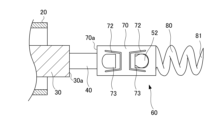
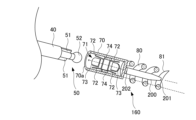
- FIG. 1 is an overall view of a delivery system 10 used to indwell a medical marker 60 in a patient's body in a first embodiment of the present invention.
- the distal end of the outer tube 20 is drawn in cross section for clarity of illustration, and the inside of the distal end of the outer tube 20 is illustrated.
- the delivery system 10 shown in FIG. 1 includes an outer tube 20, a sheath 30 inserted through the outer tube 20, a shaft member 40 inserted through the sheath 30, and a distal end of the shaft member 40 integrated with the shaft member 40. , a medical marker 60 removably connected to the engaging portion 50 , and an operating mechanism 90 connected to the proximal end sides of the sheath 30 and the shaft member 40 .
- the outer tube 20 is a flexible tubular elongated member.
- the outer diameter of the outer tube 20 is set to a size that allows it to be inserted into the channel of the endoscope 100 (see FIG. 10), and the inner diameter of the outer tube 20 is set to a size that allows the sheath 30 to be inserted therethrough.
- the material of the outer tube 20 is not particularly limited, but a flexible resin or the like can be used.
- the sheath 30 is a flexible tubular elongated member.
- the outer diameter of the sheath 30 is set to a size that allows it to be inserted into the outer tube 20, the inner diameter of the sheath 30 is set to a size that allows the shaft member 40 to be inserted, and the outer diameter of the base material 70 located at the proximal end of the medical marker 60. is set smaller.
- the sheath 30 is used to push out the medical marker 60 when the medical marker 60 is removed from the engagement portion 50 formed integrally with the shaft member 40 at the distal end of the shaft member 40 .
- the material of the sheath 30 is not particularly limited, but may be made of, for example, a tightly wound flat metal coil or the like so as to have rigidity in the axial direction.
- the shaft member 40 is a flexible and elongated member.
- the outer diameter of the shaft member 40 is set to a size that allows it to be inserted into the sheath 30.
- the shaft member 40 is a member capable of transmitting torque, and when the proximal end of the shaft member 40 is rotated around the axial direction in the operating mechanism 90, the distal end of the shaft member 40 is also rotated in the same manner. It is configured as follows.
- the shaft member 40 can be made of, for example, a flexible cable, wire, pipe, or the like.
- the engaging portion 50 is formed integrally with the shaft member 40 at the distal end of the shaft member 40, and is configured to rotate together with the shaft member 40.
- a distal end of the engaging portion 50 is removably connected to a proximal end of the medical marker 60. Further, the engaging portion 50 transmits the rotation of the engaging portion 50 to the medical marker 60 in a state connected to the proximal end portion of the medical marker 60 to cause the medical marker 60 to rotate. It is composed of
- the shape of the distal end portion of the engaging portion 50 is not particularly limited as long as it can be detachably connected to the proximal end portion of the medical marker 60.
- the shape of the distal end portion of the engaging portion 50 is The distal end of the medical marker 50 is provided with a spherical member 52, which can be inserted into an engaging portion receiving hole 71 provided in the base material 70 of the medical marker 60.
- the medical marker 60 includes a base material 70 disposed on the proximal side and connectable to the distal end of the engaging portion 50, and a coil member disposed on the distal side and formed into a spiral (coil shape). 80.
- the outer diameter of the medical marker 60 is set to a size that allows it to be inserted into the outer tube 20. Further, the outer diameter of the base material 70 located at the proximal end of the medical marker 60 is set to be larger than the inner diameter of the sheath 30 so that the distal end of the sheath 30 comes into contact with it.
- the distal end portion of the engaging portion 50 is detachably connected to the base member 70 disposed at the proximal end portion of the medical marker 60.
- the base material 70 is configured such that the rotation of the engagement portion 50 is transmitted when the base material 70 is connected to the engagement portion 50, so that the rotation of the shaft member 40 is transmitted to the engagement portion 50 and the medical device.
- the information is transmitted to the medical marker 60 via the base material 70 of the medical marker 60, and the medical marker 60 can rotate in conjunction with the rotation of the shaft member 40.
- the shape of the base material 70 is not particularly limited as long as the engaging portion 50 can be detachably connected to it.
- An engaging portion accommodating hole 71 that is open on the distal end side is formed so that the spherical member 52 of the engaging portion 50 can be inserted into the engaging portion accommodating hole 71.
- the coil member 80 disposed at the distal end of the medical marker 60 is formed into a spiral shape (coil shape), and is composed of a coil in which an elongated member extends while being wound spirally around the axial direction. has been done.
- a proximal end of coil member 80 is connected to a distal end of substrate 70.
- the distal end of the coil member 80 is preferably formed into a sharp shape that becomes thinner toward the distalmost end 81, which is the distal end thereof, and can pierce the inner wall of a hollow organ. .
- the number of turns of the coil and the pitch of the coil in the coil member 80 are not particularly limited, and may be set depending on the hollow organ to which the coil member 80 is applied. Further, the pitch of the coils may be configured to differ along the axial direction.
- the coil member 80 disposed at the distal end is made of a fluorescent material containing a fluorescent dye.
- the coil member 80 penetrates into the body tissue that is the inner wall of a hollow organ.
- the fluorescent substance can be placed inside the tissue, and the fluorescence of the fluorescent substance can be visually recognized from outside the hollow organ.
- Only a portion of the coil member 80 may be composed of a fluorescent substance containing a fluorescent dye, and in this case as well, Visibility of fluorescence from the outside can be ensured.
- the area of the phosphor's fluorescent screen (equal to the irradiation surface of the excitation light from the outside of the luminal organ) is increased, the visibility of the fluorescence of the phosphor from the outside of the luminal organ improves; Since the coil member 80 can be manufactured easily, it is preferable that the entire coil member 80 is made of a phosphor containing a fluorescent dye.
- the base material 70 disposed at the proximal end of the medical marker 60 and the coil member 80 disposed at the distal end may be constructed using the same material, or may be constructed using different materials. It may be configured as follows. In the medical marker 60, for example, both the base material 70 and the coil member 80 may be made of an integral fluorescent material. Alternatively, the base material 70 made of metal or the like and the coil member 80 made of phosphor may be joined.
- the fluorescent dye is preferably one that emits fluorescence in the red to near-infrared wavelength range of 600 to 1400 nm.
- Light in such a wavelength range is highly transparent to human tissues such as skin, fat, and muscle, and can reach as far as 5 to 20 mm below the surface of the tissues of the living body.
- Fluorescent dyes that emit fluorescence in the above wavelength range include water-soluble dyes such as riboflavin, thiamine, NADH (nicotinamide adenine dinucleotide), and indocyanine green (ICG), and azo-boron described in JP-A No. 2011-162445.
- Oil-soluble dyes such as complex compounds can be used.
- dyes that are highly compatible with polymeric materials are preferred from the viewpoint of being stably retained in polymeric materials without being eluted in the body, and in particular, azo-boron complex compounds described in JP 2011-162445A and the like. is preferable because it has excellent fluorescence emission intensity, compatibility with polymeric materials such as polyurethane, light resistance, and heat resistance.
- a phosphor containing a fluorescent dye can be produced using a polymeric material composition.
- the entire coil member 80 can be made to contain the fluorescent dye by using a polymeric material containing a fluorescent dye as the molten material.
- a part or the whole of the phosphor may be produced using a matrix made of an inorganic material such as glass or ceramics, for example, by dispersing fluorescent particles containing the above-mentioned fluorescent dye in a matrix made of an inorganic material.
- the obtained inorganic fluorescent material may be used as a fluorescent material constituting the medical marker 60.
- the outer surface of the coil member 80 may be further coated with a transparent material that does not contain a fluorescent dye.
- the preferred concentration of the fluorescent dye in the polymeric material composition containing the fluorescent dye depends on the type of fluorescent dye and the polymeric material used as the binder, but it is usually preferably 0.001 to 0.1% by mass.
- polyurethane polycarbonate, polypropylene, polyethylene, polyvinyl chloride, polyamide, polyamide elastomer, etc. can be used.
- a contrast agent such as barium sulfate may be added to the polymeric material composition containing a fluorescent dye, if necessary.
- the operating mechanism 90 is connected to the sheath 30 and the shaft member 40 at the proximal end side, and is an operating section that allows the operator to operate the present delivery system 10 when indwelling the medical marker 60 in the body.
- the operating mechanism 90 is a shaft member that rotates the medical marker 60 connected to the engaging portion 50 disposed at the distal end of the shaft member 40 by rotating the shaft member 40 in the axial direction. It is configured to include a rotation mechanism 91 and a sheath advancement/retraction mechanism 92 that moves the sheath 30 forward and backward relative to the shaft member 40 in the axial direction.
- the shaft member rotation mechanism 91 has a shaft member rotation function of rotating the shaft member 40 around the axial direction, and its configuration is not particularly limited as long as it has the shaft member rotation function.
- the shaft member rotation mechanism 91 in the first embodiment includes, for example, a worm gear 91a attached to the proximal end of the shaft member 40, and a drive provided in an internal slot of a rotation operation member 91b and engaged with the worm gear 91a. It consists of a bar.
- the rotation operation member 91b is displaced to the proximal end side
- the drive bar is displaced to the proximal end side
- the worm gear 91a rotates in the first direction
- the shaft member 40 accordingly rotates around its axial direction. It is adapted to rotate in a first direction.
- the drive bar is displaced toward the distal end, causing the worm gear 91a to rotate in a second direction opposite to the first direction.
- the shaft member 40 is configured to rotate in the second direction around its axial direction.
- the medical marker 60 connected to the engaging portion 50 disposed at the distal end of the shaft member 40 also rotates in the same direction as the shaft member 40.
- the distalmost end 81 of the coil member 80 moves forward along the rotation direction. It is assumed that the coil member 80 is adapted to pierce the inner wall of the hollow organ so that the coil member 80 penetrates inside the inner wall of the hollow organ. Furthermore, when the medical marker 60 is rotated in the second direction by displacing the rotation operation member 91b toward the distal end, the distalmost end 81 of the coil member 80 retreats along the rotation direction. , it is assumed that the coil member 80 can be removed from the inner wall of the hollow organ.
- the medical marker 60 when the rotation operation member 91b is displaced toward the proximal end, the medical marker 60 can be attached to the inner wall of the hollow organ, and when the rotation operation member 91b is displaced toward the distal end, the medical marker 60 can be attached to the inner wall of the hollow organ. can be removed from the inner wall of the hollow organ.
- the sheath advancing/retracting mechanism 92 has a sheath advancing/retracting function for moving the sheath 30 relatively forward/backward in the axial direction with respect to the shaft member 40, and as long as it has the sheath advancing/retracting function, its configuration is not particularly limited. Not done.
- the sheath advancing/retracting mechanism 92 in the first embodiment includes, as an example, an advancing/retracting operation member 92a connected to the proximal end of the sheath 30.
- an advancing/retracting operation member 92a connected to the proximal end of the sheath 30.
- the sheath 30 advances toward the distal end with respect to the shaft member 40, and when the advancement/retraction operation member 92a is slid toward the proximal end, the sheath 30 is advanced toward the shaft member 40.
- 30 is adapted to be retracted toward the proximal end.
- the proximal end 70a of the base member 70 connected to the engaging portion 50 disposed at the distal end of the shaft member 40 The medical marker 60 can be pushed out toward the distal end side by contacting with the medical marker 60, and the engagement between the engaging portion 50 and the medical marker 60 can be released. That is, by displacing the advancement/retraction operation member 92a toward the distal end, the medical marker 60 can be removed from the engagement portion 50 that is integrally formed at the distal end of the shaft member 40. .
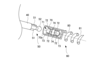
- FIG. 2 is an enlarged view of the vicinity of the distal end of the delivery system 10 shown in FIG. 1, showing the vicinity of the medical marker 60 in the first embodiment of the present invention.
- 6 is a diagram showing a state in which a medical marker 60 in an embodiment is exposed from the distal end of the outer tube 20.
- FIG. 4 is a diagram showing a state in which the medical marker 60 according to the first embodiment of the present invention is disconnected from the engaging portion 50 disposed at the distal end of the shaft member 40
- FIG. A perspective view of the state shown in FIG. 4, and FIG. 6 are views schematically showing the inside of the medical marker 60 by drawing the medical marker 60 in cross section in the perspective view shown in FIG.
- FIG. 7 is a diagram showing a medical marker 60 according to the first embodiment of the present invention connected to an engaging part 50 disposed at the distal end of the shaft member 40
- FIG. A perspective view of the state shown in FIG. 9 is a cross-sectional view of the medical marker 60 in the perspective view shown in FIG. 8 to schematically show the inside of the medical marker 60.
- the medical marker 60 in the first embodiment is connected to the sheath 30 and the engaging portion 50 disposed at the distal end of the shaft member 40 inserted through the sheath 30. It is housed in the inner cavity of the outer tube 20 together with the shaft member 40 .
- the outer tube 20 is inserted into the body together with the sheath 30 and the shaft member 40 through the channel of the endoscope 100 (see FIG. 10) and brought to the position where the medical marker 60 is placed, as shown in FIG.
- the sheath 30 and the distal end of the shaft member 40 are exposed from the distal end of the outer tube 20.
- the engaging portion 50 and the medical marker 60 which are formed integrally with the shaft member at the distal end of the shaft member 40, can be removably connected.
- the engaging part 50 is inserted into the medical marker 60 from the proximal end side.
- the engaging portion 50 and the medical marker 60 can be connected as shown in FIGS. 7 to 9.
- the engaging part 50 and the medical marker 60 are connected as shown in FIGS. 7 to 9 by removing the engaging part 50 from the medical marker 60, As shown in FIG. 6, the connection between the engaging portion 50 and the medical marker 60 can be released.
- An engaging part 50 formed integrally with the shaft member at the distal end of the shaft member 40 has a rotary engaging part 51 formed at the proximal end side that connects with the shaft member 40, and a rotary engaging part 51 formed at the distal end side. It has a spherical member 52 formed therein.
- the rotation engagement portion 51 can be configured by, for example, a pair of plate-shaped members.
- a pair of plate-like members constituting the rotational engagement portion 51 are respectively arranged at positions opposite to the outer peripheral surface of the engagement portion 50 (positions rotated by 180° in the axial direction), and the plate surfaces thereof are axially (See FIGS. 4 to 6 and 9).
- the spherical member 52 is arranged at the distal end of the engagement portion 50.
- the outer diameter of the spherical member 52 is set to be smaller than the radial width of the pair of plate-like members that constitute the rotational engagement portion 51 (the width between the outer peripheral surfaces of the rotational engagement portion 51).
- the member arranged at the distal end of the engaging part 50 is made spherical so that it can be smoothly inserted into the engaging part accommodation hole 71 of the medical marker 60.
- the shape of the member disposed at the distal end is not limited to a spherical shape, and may be, for example, an arrowhead shape that is tapered on the distal end side.
- the rotating engagement portion 51 and the spherical member 52 that constitute the engagement portion 50 are inserted into the engagement portion accommodation hole 71 provided in the cylindrical base material 70 of the medical marker 60. , a medical marker 60 can be connected to the engaging portion 50. Furthermore, in the illustrated configuration, the rotational engagement portion 51 is accommodated in the engagement portion accommodation hole 71 together with the spherical member 52 (see FIGS. 7 to 9).
- the base material 70 disposed on the proximal side of the medical marker 60 has a cylindrical shape, and has an engaging part accommodation hole 71 that can accommodate the spherical member 52 of the engaging part 50 inside the base material 70. (See FIGS. 6 and 9). That is, the engaging portion housing hole 71 is a space defined by the inner circumferential surface of the cylindrical base material 70, and the spherical member 52 of the engaging portion 50 can be inserted into the engaging portion housing hole 71. ing.
- the proximal end of the engaging portion receiving hole 71 is open so that the spherical member 52 of the engaging portion 50 can be inserted therein.
- a space capable of accommodating the spherical member 52 of the engaging portion 50 is formed on the distal end side of the engaging portion accommodating hole 71 .
- the spherical member 52 accommodated in the distal end side of the engaging portion accommodating hole 71 is configured such that it will not come out of the engaging portion accommodating hole 71 unless the spherical member 52 is pulled toward the proximal side in the axial direction with a predetermined force or more. It is engaged with the base material 70.
- the sheath 30 moves forward with respect to the spherical member 52 of the engagement part 50 and a force is exerted on the distal end 30a of the sheath 30 to push out the base material 70, the spherical member 52 moves into the engagement part accommodation. It comes out of the hole 71 and the connection between the engaging part 50 and the medical marker 60 is released.
- the distal end of the engaging portion accommodation hole 71 is closed so that the spherical member 52 of the engaging portion 50 cannot pass through the base material 70.
- the distal end side of the engaging portion accommodation hole 71 may be tapered toward the distal end so that the spherical member 52 of the engaging portion 50 comes into contact with it, or A member may be provided to restrict advancement toward the distal end.
- the base material 70 disposed at the proximal end of the medical marker 60 has a through groove 72 formed in a U-shape that penetrates the outer peripheral surface of the base material 70, as shown in the figure.
- the semicircular through holes 73 may be provided at a plurality of locations, and a portion of the outer circumferential surface of the base material 70 may be thinned out.
- a through groove 72 and a through hole 73 are provided at positions on the opposite side of the outer peripheral surface (positions rotated by 180° in the axial direction). (A total of four through grooves 72 and four through holes 73) are formed.
- a notch may be formed in the proximal end 70a of the base material 70 into which the spherical member 52 of the engaging portion 50 is inserted.
- the base material 70 is provided with a rotational engagement portion 74 at a position where it can come into contact with the rotational engagement portion 51 provided on the engagement portion 50 .
- the engaging portion 50 rotates while the spherical member 52 of the engaging portion 50 is inserted into the engaging portion housing hole 71 and housed inside the base material 70, the rotating engaging portion of the engaging portion 50 rotates. 51 and the rotational engagement part 74 of the base material 70 contact in the circumferential direction of the rotation axis, the rotation of the engagement part 50 is transmitted to the base material 70, and the medical marker is attached together with the engagement part 50. 60 can be rotated.
- the rotational engagement portion 74 of the base material 70 is formed to match the rotational engagement portion 51 of the engagement portion 50.
- the rotational engagement portion 74 of the base material 70 is constituted by a pair of engagement protrusions that protrude radially inward from the inner circumferential surface of the base material 70 that defines the engagement portion accommodation hole 71.
- the pair of engagement protrusions constituting the rotational engagement portion 74 of the base material 70 are respectively arranged at positions opposite to the inner circumferential surface of the engagement portion accommodation hole 71 (positions rotated by 180° in the axial direction). (See Figures 6 and 9).
- the pair of engagement protrusions constituting the rotational engagement portion 74 do not interfere with the insertion of the spherical member 52 of the engagement portion 50 into the engagement portion accommodation hole 71, and the engagement portion 50 can be rotated. When this occurs, the rotational engagement portion 74 of the base member 70 and the rotational engagement portion 51 of the engagement portion 50 come into contact with each other, and the rotation is transmitted to the medical marker 60.
- the rotational engagement portion 51 of the engagement portion 50 and the rotational engagement portion 74 of the base material 70 of the medical marker 60 have shapes that are compatible with each other, so that The configuration is not limited as long as it rotates the medical marker 60.
- an axial groove may be provided on the inner circumferential surface of the medical marker 60 that forms the engagement portion accommodation hole 71, and a portion of the engagement portion 50 may fit into this groove;
- a protrusion protruding toward the proximal end may be provided at the proximal end 70a of the base member 70, and the groove provided in the engaging portion 50 may fit into this protrusion.
- FIG. 10 shows a mucous membrane 110 that is the inner wall of the hollow organ, a serosa 111 that is the outer wall, and a tumor 112 that has arisen on the inner wall side of the hollow organ. Note that, for clarity of illustration, the mucous membrane 110 and serosa 111 of the hollow organ are shown in cross section in FIGS. 10 to 15.
- the endoscope 100 is inserted into the body, and the distal end of the endoscope 100 is placed near the lesion (tumor 112) in the hollow organ where the medical marker 60 is placed.
- a medical marker 60 is attached to the engagement portion 50 on the distal end side of the shaft member 40 inserted through the sheath 30, and the outer tube 20, which accommodates the sheath 30 and the shaft member 40 in its inner cavity, is inserted into the channel of the endoscope 100.
- the sheath 30 and the distal end of the shaft member 40 are exposed from the distal end side of the outer tube 20 and placed near the tumor 112.
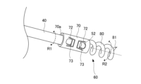
- FIGS. 11 to 15 are schematic enlarged views of the vicinity of region A in FIG. 10, and are diagrams showing the first to fifth steps of the treatment of indwelling the medical marker 60 in the hollow organ.
- the sheath 30, the engaging portion 50 formed at the distal end of the shaft member 40, and the medical marker 60 are exposed from the distal end of the outer tube 20.
- the most distal end 81 of the coil member 80 of the medical marker 60 is positioned so as to contact the inner wall of the hollow organ located near the tumor 112. Then, while pressing the most distal end 81 of the coil member 80 against the inner wall of the hollow organ, the rotation operation member 91b of the shaft member rotation mechanism 91 is displaced toward the proximal end side.
- the shaft member 40 rotates in the first direction, and the engagement portion 50 integrally formed at the distal end of the shaft member 40 rotates.
- the medical marker 60 connected to the engaging portion 50 rotates in the first direction, and the distalmost end 81 of the coil member 80 of the medical marker 60 pierces the inner wall of the hollow organ.
- the distal end 81 of the coil member 80 advances deep into the inner wall of the hollow organ, and as shown in FIG. Penetrate inside.
- the rotation operation member 91b of the shaft member rotation mechanism 91 is displaced to the distal end side to move the shaft member 40, the engaging portion 50, and the medical marker 60.
- the medical marker 60 can be removed from the inner wall of the hollow organ.
- the coil member 80 of the medical marker 60 may be repositioned to another position to penetrate the inner wall of the hollow organ.
- the distal end 30a of the sheath 30 advances toward the distal end with respect to the shaft member 40 and comes into contact with the proximal end 70a of the base member 70.
- the distal end 30a of the sheath 30 pushes the medical marker 60 toward the distal end, and the spherical member 52 of the engaging portion 50 comes out from the engaging portion receiving hole 71 of the medical marker 60.
- the medical marker 60 is removed from the engaging portion 50.
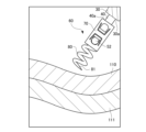
- the medical marker 60 is left in the body with the coil member 80 of the medical marker 60 penetrating the inner wall of the hollow organ.
- the outer tube 20 is taken out of the body together with the sheath 30 and the shaft member 40, and then a new A medical marker 60 is attached and the above-described steps are performed again. Thereby, as shown in FIG. 16, a plurality of new medical markers 60 can be attached to the inner wall of the hollow organ located near the tumor 112.
- the endoscope 100 is taken out of the body, and the procedure for placing the medical markers 60 is completed.
- the medical marker 60 indwelled in the body as described above at least a portion of the coil member 80 or the entire coil member 80 is made of a phosphor containing a fluorescent dye.
- the medical marker 60 is indwelled in the body with the coil member 80 penetrated into the body tissue that is the inner wall of the hollow organ. It is possible to visually check from For example, one or more medical markers 60 are placed near the lesion (tumor 112) as described above before a surgery in which a hollow organ is approached from outside, and excitation light is applied from outside the hollow organ during surgery.
- the position of the medical marker 60 can be specified by viewing the fluorescence emitted by the coil member 80 of the medical marker 60 using a camera or the like depending on the wavelength of the fluorescence. ) can be identified from outside the hollow organ.
- FIG. 17 is a perspective view showing a state in which the medical marker 160 and the engaging portion 50 disposed at the distal end of the shaft member 40 are disconnected in the second embodiment of the present invention.
- 18 is a diagram schematically showing the inside of the medical marker 160 by drawing the medical marker 160 in cross section in the perspective view shown in FIG.
- a medical marker 160 according to the second embodiment has a fluorescent member 200 in the inner cavity formed by the coil member 80 in addition to the medical marker 60 according to the first embodiment. It has a set configuration.
- the fluorescent member 200 is, for example, a member that extends in the axial direction, and is arranged so that its extending direction coincides with the axial center line of the coil member 80.
- the distal end 201 of the fluorescent member 200 is disposed proximal to the most distal end 81 of the coil member 80 so as not to prevent the coil member 80 from penetrating the inner wall of the hollow organ. It is preferable that the fluorescent member 200 is housed inside.
- the other components of the medical marker 160 in the second embodiment are the same as those in the medical marker 60 in the first embodiment, and their explanation will be omitted.
- the fluorescent member 200 is made of a phosphor that at least partially contains a fluorescent dye. Only a portion of the fluorescent member 200 (for example, from the middle of the fluorescent member 200 to the distal end 201) may be composed of a fluorescent material containing a fluorescent dye. However, if the area of the phosphor's fluorescent screen (equal to the irradiation surface of the excitation light from the outside of the luminal organ) is increased, the visibility of the fluorescence of the phosphor from the outside of the luminal organ improves; Since the fluorescent member 200 can be manufactured easily, it is preferable that the entire fluorescent member 200 is made of a fluorescent material containing a fluorescent dye.
- the shape of the fluorescent member 200 is not particularly limited, the fluorescent member 200 may have a cylindrical shape, and the end surface of the distal end 201 may have a planar shape perpendicular to the axial direction.
- the distal end 201 of the fluorescent member 200 may be tapered toward the distal end, allowing it to pierce the inner wall of a hollow organ. It may be formed into a sharp shape.
- the fluorescent member 200 may be formed into a coil shape or a drill shape.
- the proximal end 202 of the fluorescent member 200 is fixed to the distal end of the base material 70.
- the fluorescent member 200 fixed to the base material 70 of the medical marker 160 also rotates.
- the fluorescent member 200 penetrates into the body tissue that is the inner wall of the hollow organ, the fluorescent member 200 also moves forward together with the coil member 80 and comes into contact with the inner wall of the hollow organ.
- the distalmost end 81 of the coil member 80 is flat, it advances while pressing the inner wall surface of the hollow organ.
- the distal end 201 of the fluorescent member 200 has a shape that becomes narrower toward the distal end side or has a sharper shape
- the distal end 201 of the fluorescent member 200 is shaped like the coil member 80.
- the fluorescent member 200 can be penetrated into the inner wall surface of the hollow organ by penetrating the inner wall surface of the hollow organ.
- the fluorescent member 200 and the base material 70 and coil member 80 of the medical marker 160 may be constructed using the same material or may be constructed using different materials.
- the fluorescent member 200, the base material 70, and the coil member 80 may be made of an integrated fluorescent substance.
- a cylindrical member made of metal or the like is processed by laser cutting or the like to form the base material 70 and the coil member 80, and then the proximal end 202 of the fluorescent member 200 partially or entirely made of fluorescent material. may be joined to the distal end of the base member 70.
- the medical marker 160 in the second embodiment can be placed in a hollow organ using a method similar to the procedure for placing the medical marker 160 in a hollow organ in the first embodiment described above.
- the fluorescent member 200 digs deep into the inner wall of the hollow organ, or Penetrate inside the inner wall of an organ. This makes it possible to visually recognize the fluorescence of the phosphor constituting the fluorescent member 200 from outside the hollow organ.
- the configuration of the medical marker 60 in the first embodiment and the configuration of the medical marker 160 in the second embodiment at least a portion of the coil member 80 or the entire coil member 80 is configured with a fluorescent material. Furthermore, a structure may be adopted in which the fluorescent member 200 is arranged inside the coil member 80.
- the medical markers 60 and 160 in the first and second embodiments are placed in a hollow organ in the body, and include a cylindrical base material 70 constituting a proximal end and a distal end.
- the coil member 80 is integrally formed with a coil member 80 formed so as to extend while being spirally wound around the axial direction.
- the coil member 80 constituting the distal end of the medical marker 60 in the first embodiment is at least partially or entirely made of a phosphor containing a fluorescent dye that emits fluorescence in a predetermined wavelength range when irradiated with excitation light. It is configured.
- a fluorescent member 200 At the distal end of the medical marker 160 in the second embodiment, there is a fluorescent member 200 at least partially or entirely made of a fluorescent substance containing a fluorescent dye that emits fluorescence in a predetermined wavelength range when irradiated with excitation light. is provided so as to extend in the axial direction in the inner cavity formed by the coil member 80.
- the fluorescent member 200 may be shaped such that its distal end 201 becomes thinner toward the distal end.
- the medical markers 60 and 160 in the first and second embodiments can penetrate inside the inner wall of a hollow organ while the coil member 80 rotates, and can be stably attached to the inner wall of a hollow organ. It is excellent and has an improved retention period.
- the positions of the medical markers 60 and 160 can be identified by visually recognizing the fluorescence emitted by the fluorescent substance, and the position of the medical markers 60 and 160 can be identified from outside the hollow organ. It has excellent visibility.
- the coil member 80 itself that penetrates inside the inner wall of the hollow organ is made of fluorescent material, when the medical marker 60 is attached to the inner wall of the hollow organ, It becomes possible to place the phosphor inside the inner wall of the hollow organ.
- the fluorescent member 200 made of fluorescent substance is placed near the inner wall of the hollow organ. It has excellent visibility from the outside of the hollow organ. Further, by providing the fluorescent member 200 as a separate member of the coil member 80, the coil member 80 can be made of metal or the like, for example, and the mounting stability of the medical marker 160 can be maintained. Furthermore, by shaping the distal end 201 of the fluorescent member 200 so that it becomes thinner toward the distal end, the fluorescent member 200 can penetrate inside the inner wall of the hollow organ, and from the outside of the hollow organ. visibility can be improved.
- the medical markers 60 and 160 in the first and second embodiments may be formed such that the distal end of the coil member 80 becomes thinner toward the distal end side. Thereby, the distal end of the coil member 80 pierces the inner wall of the hollow organ, thereby improving the ability to penetrate into the inner wall of the hollow organ.
- the base material 70 is removably connected to the distal end of the shaft member 40 capable of transmitting torque, and the base material 70 and the coil member 80 may be configured to rotate.
- the medical markers 60, 160 including the base material 70 and the coil member 80 are rotated, and the coil member 80 is made to penetrate inside the inner wall of the hollow organ. I can do it.
Landscapes
- Health & Medical Sciences (AREA)
- Surgery (AREA)
- Life Sciences & Earth Sciences (AREA)
- Heart & Thoracic Surgery (AREA)
- Pathology (AREA)
- Oral & Maxillofacial Surgery (AREA)
- Engineering & Computer Science (AREA)
- Biomedical Technology (AREA)
- Nuclear Medicine, Radiotherapy & Molecular Imaging (AREA)
- Medical Informatics (AREA)
- Molecular Biology (AREA)
- Animal Behavior & Ethology (AREA)
- General Health & Medical Sciences (AREA)
- Public Health (AREA)
- Veterinary Medicine (AREA)
- Media Introduction/Drainage Providing Device (AREA)
Abstract
In order to provide a medical marker that achieves excellent attaching stability, which enhances the indwelling period, and that achieves excellent visibility from the exterior of a hollow organ, a medical marker (60) according to the present invention is indwelled inside a hollow organ in a body and includes, as an integral component, a cylindrical base material (70), which forms a proximal end section, and a coil member (80), which forms a distal end section and extends while winding about the axial direction in a spiral manner, wherein a phosphor containing a fluorescent dye that emits fluorescence in a prescribed wavelength range due to excitation light irradiation is disposed in the distal end section. For example, the coil member (80) forming the distal end section of the medical marker (60) is at least partially or entirely formed from the phosphor.
Description
本発明は、例えば内視鏡を利用して管腔臓器内に挿入されて、管腔臓器の外側から位置を視認可能なマーカーとして利用することができる医療用マーカーに関する。
The present invention relates to a medical marker that can be inserted into a hollow organ using, for example, an endoscope and used as a marker whose position can be visually recognized from outside the hollow organ.
一般に、食道、胃、大腸等の消化管の癌等の疾患は、主として消化管の粘膜から発生し進行する。同様に、肺癌は、主として気管粘膜から発生し、膀胱癌は、主として膀胱粘膜から発生し進行する。そのため、消化管、気管、膀胱等の管腔臓器の疾患の診断を確定させるには、内視鏡を管腔臓器内に挿入して粘膜を観察し、患部組織を生検することが必須となっている。そして、その確定診断に基づき、患部組織は必要に応じて外科的に切除される。
In general, diseases such as cancer of the gastrointestinal tract, such as the esophagus, stomach, and large intestine, mainly develop and progress from the mucous membrane of the gastrointestinal tract. Similarly, lung cancer primarily originates from the tracheal mucosa, and bladder cancer primarily originates and progresses from the bladder mucosa. Therefore, in order to confirm the diagnosis of diseases in hollow organs such as the gastrointestinal tract, trachea, and bladder, it is essential to insert an endoscope into the hollow organs, observe the mucous membranes, and biopsy the affected tissues. It has become. Then, based on the definitive diagnosis, the affected tissue is surgically removed as necessary.
しかしながら、外科的切除術において、外科医は管腔臓器の外側からアプローチするため、管腔臓器内の患部を直接的に視認することはできない。すなわち、開胸または開腹手術下や腹腔鏡手術下では、肉眼または腹腔鏡で消化管、肺または膀胱を観察した場合、見えるのは粘膜ではなく、消化管漿膜面、気管漿膜面、膀胱腹膜面である。そのため、管腔臓器の外側から観察した場合でも切除域を確定できるように、管腔臓器の内側からマーキングを行うことが必要となる。
However, in surgical resection, the surgeon approaches from outside the hollow organ, and therefore cannot directly visualize the affected area within the hollow organ. In other words, when observing the gastrointestinal tract, lungs, or bladder with the naked eye or laparoscope during thoracotomy or laparoscopic surgery, what is visible is not the mucous membrane, but the gastrointestinal serosal surface, tracheal serosal surface, and bladder peritoneal surface. It is. Therefore, it is necessary to mark from the inside of the hollow organ so that the resection area can be determined even when the hollow organ is observed from the outside.
このようなマーキングを行うためのマーカーとして、例えば下記の特許文献1に記載されている医療用マーカーが知られている。特許文献1には、弾力で略V字状に開脚する一対のアーム板部と、アーム板部の各先端部に形成してある爪部と、一対のアーム板部の長手方向に沿って移動可能にアーム板部に取り付けられ、爪部の方向に移動させることにより、一対のアーム板部を閉脚させる締め付けリングとを有し、少なくともいずれか一方の爪部の外面に、励起光の照射により所定の波長域の蛍光を発光する蛍光色素を含む蛍光部材と、励起光および蛍光の少なくとも一方を反射する反射材とを設けたクリップ状の医療用マーカーが記載されている。
As a marker for performing such marking, for example, a medical marker described in Patent Document 1 below is known. Patent Document 1 describes a pair of arm plate parts that open into a substantially V-shape with elasticity, a claw part formed at each tip of the arm plate part, and a claw part formed on each tip of the arm plate part, and a pair of arm plate parts that extend along the longitudinal direction of the pair of arm plate parts. It has a tightening ring that is movably attached to the arm plate and closes the pair of arm plates by moving it in the direction of the claw, and irradiates the outer surface of at least one of the claws with excitation light. A clip-shaped medical marker is described that includes a fluorescent member containing a fluorescent dye that emits fluorescence in a predetermined wavelength range, and a reflective material that reflects at least one of excitation light and fluorescence.
特許文献1に記載されている医療用マーカーは、そのクリップ形状により管腔臓器の内壁に取り付けることが容易であるとともに、管腔臓器の内壁に入り込んだ位置に蛍光部材および反射材を配置されて管腔臓器の外側から蛍光の視認が可能となるため、その取り付け位置を容易に特定することができるので有用であるものの、クリップの把持力は必ずしも強くはないという課題がある。
The medical marker described in Patent Document 1 can be easily attached to the inner wall of a hollow organ due to its clip shape, and a fluorescent member and a reflective material are arranged at a position that penetrates into the inner wall of the hollow organ. Since fluorescence can be visually recognized from the outside of the hollow organ, it is useful because the attachment position can be easily specified, but there is a problem that the gripping force of the clip is not necessarily strong.
医療用蛍光マーカーは、手術前に管腔臓器内の患部近傍に、当該患部の位置を把握できるように取り付けられて、手術時まで留置される必要がある。この点、特許文献1に記載されている医療用マーカーは、クリップの把持力は必ずしも強くはないことから、体内に留置可能な期間は必ずしも長くはない(例えば3日程度)という課題があり、医療現場では、より長くかつ確実に体内に留置することが可能な医療用マーカーが要望されている。
A medical fluorescent marker needs to be attached to the vicinity of the affected area in a hollow organ before surgery so that the location of the affected area can be determined and left in place until the time of surgery. In this regard, the medical marker described in Patent Document 1 has the problem that the gripping force of the clip is not necessarily strong, so the period that it can be left in the body is not necessarily long (for example, about 3 days). In the medical field, there is a demand for medical markers that can be left in the body for longer and more reliably.
本発明は、上記の課題に鑑みてなされたものであり、取付安定性に優れて留置可能期間が向上されるとともに、管腔臓器の外側からの視認性に優れた医療用マーカーを提供することを目的とする。
The present invention has been made in view of the above-mentioned problems, and an object of the present invention is to provide a medical marker that has excellent attachment stability and can be indwelled for an extended period of time, and has excellent visibility from the outside of a hollow organ. With the goal.
上記の目的を達成するため、本発明に係る医療用マーカーは、体内の管腔臓器内に留置される医療用マーカーであって、近位端部を構成する筒状の基材と、遠位端部を構成し、軸方向周りで螺旋状に巻回しながら延在するように成形されたコイル部材と、を一体に備えており、前記遠位端部に、励起光の照射により所定の波長域の蛍光を発する蛍光色素を含有した蛍光体が配置されていることを特徴とする。
In order to achieve the above object, the medical marker according to the present invention is a medical marker that is indwelled in a hollow organ in the body, and includes a cylindrical base material constituting a proximal end portion and a distal end portion. The distal end portion is integrally formed with a coil member formed to extend while being spirally wound around the axial direction, and the distal end portion is irradiated with a predetermined wavelength of excitation light. It is characterized in that a phosphor containing a fluorescent dye that emits fluorescence in the area is arranged.
上記の構成によれば、医療用マーカーの遠位端部が、軸方向周りで螺旋状に巻回しながら延在するように成形されたコイル部材で構成されており、当該遠位端部に蛍光色素を含有した蛍光体が配置されている。これにより、コイル部材が回動しながら管腔臓器の内壁の内側に穿入することができ、管腔臓器の内壁への取付安定性に優れ、留置可能期間が向上された医療用マーカーを提供することができる。また、蛍光体が管腔臓器の内壁の近傍に配置されるので、蛍光体が発する蛍光を視認することで医療用マーカーの位置を特定できるようになり、管腔臓器の外側からの視認性に優れた医療用マーカーを提供することができる。
According to the above configuration, the distal end of the medical marker is formed of a coil member formed to extend while being spirally wound around the axial direction, and the distal end is provided with fluorescent light. A phosphor containing a dye is arranged. This allows the coil member to penetrate inside the inner wall of the hollow organ while rotating, providing a medical marker with excellent attachment stability to the inner wall of the hollow organ and an improved indwelling period. can do. In addition, since the fluorescent substance is placed near the inner wall of the hollow organ, it becomes possible to identify the position of the medical marker by visually recognizing the fluorescence emitted by the fluorescent substance, improving visibility from the outside of the hollow organ. It can provide excellent medical markers.
本発明に係る医療用マーカーは、上記の構成において、前記コイル部材の少なくとも一部または全体が前記蛍光体によって構成されていてもよい。
In the medical marker according to the present invention, in the above configuration, at least a portion or the entirety of the coil member may be constituted by the fluorescent substance.
上記の構成によれば、管腔臓器の内壁の内側に穿入するコイル部材自体が蛍光体で構成されるので、医療用マーカーを管腔臓器の内壁に取り付けた際に蛍光色素を含有した蛍光体を管腔臓器の内壁の内側に配置することができ、管腔臓器の外側からの視認性に優れた医療用マーカーを提供することができる。
According to the above configuration, since the coil member itself that penetrates inside the inner wall of the hollow organ is made of fluorescent substance, when the medical marker is attached to the inner wall of the hollow organ, the fluorescent dye containing fluorescent A medical marker that can be placed inside the inner wall of a hollow organ and has excellent visibility from outside the hollow organ can be provided.
本発明に係る医療用マーカーは、上記の構成において、少なくとも一部または全体が前記蛍光体によって構成された蛍光部材が、前記コイル部材により形成される内腔において軸方向に延在するように設けられていてもよい。
In the medical marker according to the present invention, in the above configuration, the fluorescent member at least partially or entirely made of the fluorescent substance is provided to extend in the axial direction in the inner cavity formed by the coil member. It may be.
上記の構成によれば、医療用マーカーを管腔臓器の内壁に取り付けた際に、管腔臓器の内壁の近傍に蛍光体によって構成された蛍光部材が配置されるので、管腔臓器の外側からの視認性に優れた医療用マーカーを提供することができる。また、コイル部材の別体として蛍光部材を設けることで、例えばコイル部材を金属等によって構成することができ、医療用マーカーの取付安定性を維持することができるようになる。
According to the above configuration, when the medical marker is attached to the inner wall of the hollow organ, the fluorescent member made of fluorescent substance is placed near the inner wall of the hollow organ, so that it can be seen from the outside of the hollow organ. It is possible to provide a medical marker with excellent visibility. Further, by providing a fluorescent member as a separate member of the coil member, the coil member can be made of metal or the like, and the stability of attachment of the medical marker can be maintained.
本発明に係る医療用マーカーは、上記の構成において、前記蛍光部材の遠位端が遠位端側に向かって細くなるように成形されていてもよい。
In the medical marker according to the present invention, in the above configuration, the distal end of the fluorescent member may be formed to become thinner toward the distal end side.
上記の構成によれば、医療用マーカーを管腔臓器の内壁に取り付けた際に、蛍光部材が管腔臓器の内壁の内側に穿入可能となるので、蛍光部材を管腔臓器の内壁の内側に配置することができ、管腔臓器の外側からの視認性に優れた医療用マーカーを提供することができる。
According to the above configuration, when the medical marker is attached to the inner wall of the hollow organ, the fluorescent member can penetrate inside the inner wall of the hollow organ. It is possible to provide a medical marker with excellent visibility from the outside of a hollow organ.
本発明に係る医療用マーカーは、上記の構成において、前記コイル部材の遠位端が遠位端側に向かって細くなるように成形されていてもよい。
In the medical marker according to the present invention, in the above configuration, the distal end of the coil member may be formed so that it becomes thinner toward the distal end side.
上記の構成によれば、コイル部材の遠位端が管腔臓器の内壁に突き刺さり、管腔臓器の内壁の内側への穿入性を向上させることができる。
According to the above configuration, the distal end of the coil member pierces the inner wall of the hollow organ, and it is possible to improve the ability to penetrate into the inner wall of the hollow organ.
本発明に係る医療用マーカーは、上記の構成において、前記基材がトルク伝達可能な軸部材の遠位端と着脱可能に連結して、前記軸部材の回動に応じて前記基材および前記コイル部材が回動するように構成されていてもよい。
In the medical marker according to the present invention, in the above configuration, the base material is removably connected to the distal end of the shaft member capable of transmitting torque, and the base material and the The coil member may be configured to rotate.
上記の構成によれば、軸部材を回動させることによって、基材およびコイル部材を備えた医療用マーカーを回動させ、コイル部材を管腔臓器の内壁の内側へ穿入させることができる。
According to the above configuration, by rotating the shaft member, the medical marker including the base material and the coil member can be rotated, and the coil member can penetrate inside the inner wall of the hollow organ.
以下、図面を参照しながら、本発明の実施形態について説明する。本明細書では、本発明に係る医療用マーカーを患者の体内に留置するために使用される送達システムの操作者を基準として、患者の体内側を遠位側とし、操作者の手元側を近位側とする。本明細書において参照する図面は、実際の寸法に対して必ずしも正確な縮尺を有するものではなく、本発明に係る構成を模式的に示すために一部を誇張または簡略化したものである。
Hereinafter, embodiments of the present invention will be described with reference to the drawings. In this specification, the inside of the patient's body is referred to as the distal side, and the operator's proximal side is referred to as the near side, with the operator of the delivery system used for indwelling the medical marker according to the present invention in the patient's body as a reference. position side. The drawings referred to in this specification are not necessarily to scale with respect to actual dimensions, and are partially exaggerated or simplified in order to schematically illustrate configurations according to the present invention.
<第1実施形態>
まず、本発明の第1実施形態における医療用マーカー60について説明する。 <First embodiment>
First, themedical marker 60 according to the first embodiment of the present invention will be explained.
まず、本発明の第1実施形態における医療用マーカー60について説明する。 <First embodiment>
First, the
図1を参照しながら、医療用マーカー60を患者の体内に留置するために使用される送達システムについて説明する。図1は、本発明の第1実施形態における医療用マーカー60を患者の体内に留置するために使用される送達システム10の全体図である。なお、図1では、図示明瞭化のために外管20の遠位端部を断面で描き、外管20の遠位端部の内部を図示している。
With reference to FIG. 1, a delivery system used to indwell a medical marker 60 within a patient's body will be described. FIG. 1 is an overall view of a delivery system 10 used to indwell a medical marker 60 in a patient's body in a first embodiment of the present invention. In addition, in FIG. 1, the distal end of the outer tube 20 is drawn in cross section for clarity of illustration, and the inside of the distal end of the outer tube 20 is illustrated.
図1に示す送達システム10は、外管20と、外管20に挿通されたシース30と、シース30に挿通された軸部材40と、軸部材40の遠位端部に軸部材40と一体に形成された係合部50と、係合部50に取り外し可能に連結する医療用マーカー60と、シース30および軸部材40の近位端側に接続された操作機構90と、を有する。
The delivery system 10 shown in FIG. 1 includes an outer tube 20, a sheath 30 inserted through the outer tube 20, a shaft member 40 inserted through the sheath 30, and a distal end of the shaft member 40 integrated with the shaft member 40. , a medical marker 60 removably connected to the engaging portion 50 , and an operating mechanism 90 connected to the proximal end sides of the sheath 30 and the shaft member 40 .
外管20は、可撓性を有する管状の長尺部材である。外管20の外径は内視鏡100(図10参照)のチャネルに挿通可能な寸法に設定され、外管20の内径はシース30が挿通可能な寸法に設定される。外管20の材料は特に限定されないが、可撓性を有する樹脂等を用いることができる。
The outer tube 20 is a flexible tubular elongated member. The outer diameter of the outer tube 20 is set to a size that allows it to be inserted into the channel of the endoscope 100 (see FIG. 10), and the inner diameter of the outer tube 20 is set to a size that allows the sheath 30 to be inserted therethrough. The material of the outer tube 20 is not particularly limited, but a flexible resin or the like can be used.
シース30は、可撓性を有する管状の長尺部材である。シース30の外径は外管20に挿通可能な寸法に設定され、シース30の内径は軸部材40が挿通可能であり、医療用マーカー60の近位端部に位置する基材70の外径より小さく設定される。シース30は、軸部材40の遠位端部に軸部材40と一体に形成された係合部50から医療用マーカー60を取り外す際に医療用マーカー60を押し出すために用いられる。シース30の材料は特に限定されないが、軸線方向に剛性を有するように、例えば扁平状に密巻された金属製のコイル等などによって構成することができる。
The sheath 30 is a flexible tubular elongated member. The outer diameter of the sheath 30 is set to a size that allows it to be inserted into the outer tube 20, the inner diameter of the sheath 30 is set to a size that allows the shaft member 40 to be inserted, and the outer diameter of the base material 70 located at the proximal end of the medical marker 60. is set smaller. The sheath 30 is used to push out the medical marker 60 when the medical marker 60 is removed from the engagement portion 50 formed integrally with the shaft member 40 at the distal end of the shaft member 40 . The material of the sheath 30 is not particularly limited, but may be made of, for example, a tightly wound flat metal coil or the like so as to have rigidity in the axial direction.
軸部材40は、可撓性を有する長尺の部材である。軸部材40の外径はシース30に挿通可能な寸法に設定される。軸部材40はトルク伝達可能な部材であり、操作機構90において軸部材40の近位端部を軸線方向周りに回動させた場合に、軸部材40の遠位端部も同様に回動するように構成されている。軸部材40は、例えば可撓性のケーブル、ワイヤ、パイプ等によって構成することができる。
The shaft member 40 is a flexible and elongated member. The outer diameter of the shaft member 40 is set to a size that allows it to be inserted into the sheath 30. The shaft member 40 is a member capable of transmitting torque, and when the proximal end of the shaft member 40 is rotated around the axial direction in the operating mechanism 90, the distal end of the shaft member 40 is also rotated in the same manner. It is configured as follows. The shaft member 40 can be made of, for example, a flexible cable, wire, pipe, or the like.
係合部50は、軸部材40の遠位端部に軸部材40と一体に形成されており、軸部材40とともに回動するように構成されている。係合部50の遠位端部は、医療用マーカー60の近位端部と着脱可能に連結される。また、係合部50は、医療用マーカー60の近位端部と連結された状態において、係合部50の回動を医療用マーカー60に伝達して、医療用マーカー60を回動させるように構成されている。係合部50の遠位端部の形状は、医療用マーカー60の近位端部と着脱可能に連結できるものであれば特に限定されないが、第1実施形態では、後述するように係合部50の遠位端部は球状部材52を備えており、医療用マーカー60の基材70内に設けられた係合部収容孔71に挿入できるようになっている。
The engaging portion 50 is formed integrally with the shaft member 40 at the distal end of the shaft member 40, and is configured to rotate together with the shaft member 40. A distal end of the engaging portion 50 is removably connected to a proximal end of the medical marker 60. Further, the engaging portion 50 transmits the rotation of the engaging portion 50 to the medical marker 60 in a state connected to the proximal end portion of the medical marker 60 to cause the medical marker 60 to rotate. It is composed of The shape of the distal end portion of the engaging portion 50 is not particularly limited as long as it can be detachably connected to the proximal end portion of the medical marker 60. However, in the first embodiment, the shape of the distal end portion of the engaging portion 50 is The distal end of the medical marker 50 is provided with a spherical member 52, which can be inserted into an engaging portion receiving hole 71 provided in the base material 70 of the medical marker 60.
医療用マーカー60は、近位側に配置されて係合部50の遠位端部と連結可能な基材70と、遠位側に配置されて螺旋状(コイル状)に成形されたコイル部材80とを備えて構成されている。医療用マーカー60の外径は外管20に挿通可能な寸法に設定されている。また、医療用マーカー60の近位端部に位置する基材70の外径は、シース30の遠位端部が当接するようにシース30の内径より大きな寸法に設定されている。
The medical marker 60 includes a base material 70 disposed on the proximal side and connectable to the distal end of the engaging portion 50, and a coil member disposed on the distal side and formed into a spiral (coil shape). 80. The outer diameter of the medical marker 60 is set to a size that allows it to be inserted into the outer tube 20. Further, the outer diameter of the base material 70 located at the proximal end of the medical marker 60 is set to be larger than the inner diameter of the sheath 30 so that the distal end of the sheath 30 comes into contact with it.
医療用マーカー60の近位端部に配置されている基材70には、係合部50の遠位端部が着脱可能に連結される。基材70は、係合部50と連結された状態において係合部50の回動が伝達されるように構成されており、これにより、軸部材40の回動が、係合部50および医療用マーカー60の基材70を介して医療用マーカー60に伝達され、医療用マーカー60は、軸部材40の回動に連動して回動できるようになっている。基材70の形状は、係合部50が着脱可能に連結できるものであれば特に限定されないが、第1実施形態では、後述するように基材70は筒状であって、その内部に近位端側で開口した係合部収容孔71が形成されており、係合部50の球状部材52が係合部収容孔71に挿入できるようになっている。
The distal end portion of the engaging portion 50 is detachably connected to the base member 70 disposed at the proximal end portion of the medical marker 60. The base material 70 is configured such that the rotation of the engagement portion 50 is transmitted when the base material 70 is connected to the engagement portion 50, so that the rotation of the shaft member 40 is transmitted to the engagement portion 50 and the medical device. The information is transmitted to the medical marker 60 via the base material 70 of the medical marker 60, and the medical marker 60 can rotate in conjunction with the rotation of the shaft member 40. The shape of the base material 70 is not particularly limited as long as the engaging portion 50 can be detachably connected to it. An engaging portion accommodating hole 71 that is open on the distal end side is formed so that the spherical member 52 of the engaging portion 50 can be inserted into the engaging portion accommodating hole 71.
医療用マーカー60の遠位端部に配置されているコイル部材80は、螺旋状(コイル状)に成形されており、細長い部材が軸方向周りで螺旋状に巻回しながら延在するコイルにより構成されている。コイル部材80の近位端は基材70の遠位端に接続されている。コイル部材80の遠位端は、その先端部分である最遠位端81に向かって細くなっており、管腔臓器の内壁に突き刺さることが可能となる鋭利な形状に成形されていることが好ましい。コイル部材80におけるコイルの巻回数およびコイルのピッチは特に限定されず、適用する管腔臓器に応じて設定されてもよい。また、コイルのピッチは、軸方向に沿って異なるように構成されてもよい。
The coil member 80 disposed at the distal end of the medical marker 60 is formed into a spiral shape (coil shape), and is composed of a coil in which an elongated member extends while being wound spirally around the axial direction. has been done. A proximal end of coil member 80 is connected to a distal end of substrate 70. The distal end of the coil member 80 is preferably formed into a sharp shape that becomes thinner toward the distalmost end 81, which is the distal end thereof, and can pierce the inner wall of a hollow organ. . The number of turns of the coil and the pitch of the coil in the coil member 80 are not particularly limited, and may be set depending on the hollow organ to which the coil member 80 is applied. Further, the pitch of the coils may be configured to differ along the axial direction.
第1実施形態における医療用マーカー60は、遠位端部に配置されているコイル部材80の少なくとも一部が蛍光色素を含有した蛍光体によって構成されている。後述するように、医療用マーカー60を体内に留置する際、コイル部材80は管腔臓器の内壁である体内組織内に穿入されるが、コイル部材80が蛍光体によって構成されることで体内組織の内部に蛍光体を配置することができ、管腔臓器の外側から蛍光体の蛍光を視認することが可能となる。
In the medical marker 60 in the first embodiment, at least a portion of the coil member 80 disposed at the distal end is made of a fluorescent material containing a fluorescent dye. As will be described later, when the medical marker 60 is placed in the body, the coil member 80 penetrates into the body tissue that is the inner wall of a hollow organ. The fluorescent substance can be placed inside the tissue, and the fluorescence of the fluorescent substance can be visually recognized from outside the hollow organ.
コイル部材80は、その一部のみ(例えば、螺旋状のコイル部材80の途中から最遠位端81まで)が蛍光色素を含有した蛍光体で構成されてもよく、この場合も管腔臓器の外側からの蛍光の視認性を確保することができる。ただし、蛍光体の蛍光面(管腔臓器の外側からの励起光の照射面と等しい)の面積を大きくした場合に管腔臓器の外側からの蛍光体の蛍光の視認性が向上する点、および、コイル部材80を容易に製造できる点から、コイル部材80全体が蛍光色素を含有した蛍光体によって構成されることが好ましい。
Only a portion of the coil member 80 (for example, from the middle of the spiral coil member 80 to the most distal end 81) may be composed of a fluorescent substance containing a fluorescent dye, and in this case as well, Visibility of fluorescence from the outside can be ensured. However, if the area of the phosphor's fluorescent screen (equal to the irradiation surface of the excitation light from the outside of the luminal organ) is increased, the visibility of the fluorescence of the phosphor from the outside of the luminal organ improves; Since the coil member 80 can be manufactured easily, it is preferable that the entire coil member 80 is made of a phosphor containing a fluorescent dye.
医療用マーカー60の近位端部に配置されている基材70と、遠位端部に配置されているコイル部材80とは、同一の材料を用いて構成されてもよく、異なる材料を用いて構成されてもよい。医療用マーカー60は、例えば、基材70およびコイル部材80の両方が一体の蛍光体により構成されてもよい。あるいは、金属等で構成された基材70と蛍光体で構成されたコイル部材80とを接合してもよい。
The base material 70 disposed at the proximal end of the medical marker 60 and the coil member 80 disposed at the distal end may be constructed using the same material, or may be constructed using different materials. It may be configured as follows. In the medical marker 60, for example, both the base material 70 and the coil member 80 may be made of an integral fluorescent material. Alternatively, the base material 70 made of metal or the like and the coil member 80 made of phosphor may be joined.
蛍光色素としては、600~1400nmの赤色ないし近赤外の波長域の蛍光を発するものが好ましい。このような波長域の光は、皮膚、脂肪、筋肉等の人体組織に対して透過性が高く、生体の組織表面下5~20mm程度まで良好に到達することができる。
The fluorescent dye is preferably one that emits fluorescence in the red to near-infrared wavelength range of 600 to 1400 nm. Light in such a wavelength range is highly transparent to human tissues such as skin, fat, and muscle, and can reach as far as 5 to 20 mm below the surface of the tissues of the living body.
上述の波長域の蛍光を発する蛍光色素としては、リボフラビン、チアミン、NADH(nicotinamide adenine dinucleotide)、インドシアニングリーン(ICG)等の水溶性色素や、特開2011-162445号公報に記載のアゾ-ホウ素錯体化合物等の油溶性色素を使用することができる。中でも、体内で溶出することなく安定に高分子材料中に保持される点から高分子材料に相溶性の高い色素が好ましく、特に、特開2011-162445号公報に記載のアゾ-ホウ素錯体化合物等が蛍光の発光強度に優れ、ポリウレタン等の高分子材料に対する相溶性、耐光性、耐熱性にも優れる点で好ましい。
Fluorescent dyes that emit fluorescence in the above wavelength range include water-soluble dyes such as riboflavin, thiamine, NADH (nicotinamide adenine dinucleotide), and indocyanine green (ICG), and azo-boron described in JP-A No. 2011-162445. Oil-soluble dyes such as complex compounds can be used. Among these, dyes that are highly compatible with polymeric materials are preferred from the viewpoint of being stably retained in polymeric materials without being eluted in the body, and in particular, azo-boron complex compounds described in JP 2011-162445A and the like. is preferable because it has excellent fluorescence emission intensity, compatibility with polymeric materials such as polyurethane, light resistance, and heat resistance.
蛍光色素を含有した蛍光体は、高分子材料組成物を用いて作製することが可能である。例えば、射出成形やインサート成形によってコイル部材80を作製する場合、蛍光色素を含有させた高分子材料を溶融材料として使用することで、コイル部材80全体が蛍光色素を含むようにすることができる。また、ガラスやセラミクス等の無機材料からなるマトリクスを用いて蛍光体の一部または全体を作製してもよく、例えば上記の蛍光色素を含有した蛍光粒子を無機材料からなるマトリクスに分散させて得られた無機蛍光体を、医療用マーカー60を構成する蛍光体として用いてもよい。
A phosphor containing a fluorescent dye can be produced using a polymeric material composition. For example, when the coil member 80 is manufactured by injection molding or insert molding, the entire coil member 80 can be made to contain the fluorescent dye by using a polymeric material containing a fluorescent dye as the molten material. Further, a part or the whole of the phosphor may be produced using a matrix made of an inorganic material such as glass or ceramics, for example, by dispersing fluorescent particles containing the above-mentioned fluorescent dye in a matrix made of an inorganic material. The obtained inorganic fluorescent material may be used as a fluorescent material constituting the medical marker 60.
高分子材料に蛍光色素を含有させる方法としては、例えば、二軸混練機を使用して高分子材料に蛍光色素を混練する方法を使用することができる。また、この場合、コイル部材80の保護や生体への影響等を考慮して、蛍光色素を含有しない透明材料でコイル部材80の外表面を更にコーティングしてもよい。
As a method for incorporating the fluorescent dye into the polymeric material, for example, a method of kneading the fluorescent dye into the polymeric material using a twin-screw kneader can be used. Further, in this case, in consideration of protection of the coil member 80 and influence on living organisms, the outer surface of the coil member 80 may be further coated with a transparent material that does not contain a fluorescent dye.
蛍光色素を含む高分子材料組成物における蛍光色素の好ましい濃度は、蛍光色素やバインダーとする高分子材料の種類にもよるが、通常、0.001~0.1質量%とすることが好ましい。
The preferred concentration of the fluorescent dye in the polymeric material composition containing the fluorescent dye depends on the type of fluorescent dye and the polymeric material used as the binder, but it is usually preferably 0.001 to 0.1% by mass.
蛍光色素を含有させる高分子材料としては、ポリウレタン、ポリカーボネート、ポリプロピレン、ポリエチレン、ポリ塩化ビニル、ポリアミド、ポリアミドエラストマー等を使用することができる。
As the polymer material containing the fluorescent dye, polyurethane, polycarbonate, polypropylene, polyethylene, polyvinyl chloride, polyamide, polyamide elastomer, etc. can be used.
蛍光色素を含む高分子材料組成物には、必要に応じて硫酸バリウム等の造影剤を添加してもよい。これにより、体内で医療用マーカー60が管腔臓器の内壁から外れた場合であっても、管腔臓器内の医療用マーカー60を、X線を用いた撮影により追跡することが可能となる。
A contrast agent such as barium sulfate may be added to the polymeric material composition containing a fluorescent dye, if necessary. Thereby, even if the medical marker 60 comes off the inner wall of the hollow organ inside the body, it is possible to track the medical marker 60 inside the hollow organ by imaging using X-rays.
操作機構90は、シース30および軸部材40と近位端側で接続されており、医療用マーカー60を体内に留置する際に操作者が本送達システム10を操作可能にする操作部である。操作機構90は、軸部材40を軸方向周りに回動させることで、軸部材40の遠位端部に配置されている係合部50に連結された医療用マーカー60を回動させる軸部材回動機構91と、軸部材40に対してシース30を軸方向に相対的に進退させるシース進退機構92とを含んで構成されている。
The operating mechanism 90 is connected to the sheath 30 and the shaft member 40 at the proximal end side, and is an operating section that allows the operator to operate the present delivery system 10 when indwelling the medical marker 60 in the body. The operating mechanism 90 is a shaft member that rotates the medical marker 60 connected to the engaging portion 50 disposed at the distal end of the shaft member 40 by rotating the shaft member 40 in the axial direction. It is configured to include a rotation mechanism 91 and a sheath advancement/retraction mechanism 92 that moves the sheath 30 forward and backward relative to the shaft member 40 in the axial direction.
軸部材回動機構91は、軸部材40を軸方向周りに回動させる軸部材回動機能を有しており、当該軸部材回動機能を有するものであれば、その構成は特に限定されない。
The shaft member rotation mechanism 91 has a shaft member rotation function of rotating the shaft member 40 around the axial direction, and its configuration is not particularly limited as long as it has the shaft member rotation function.
第1実施形態における軸部材回動機構91は、一例として、軸部材40の近位端に取り付けられたウォームギア91aと、回動操作部材91bの内部スロットに設けられてウォームギア91aに係合する駆動バーとにより構成されている。回動操作部材91bを近位端側に変位させると、駆動バーが近位端側に変位してウォームギア91aが第1方向に回動し、これに伴って軸部材40がその軸線方向周りで第1方向に回動するようになっている。一方、回動操作部材91bを遠位端側に変位させると、駆動バーが遠位端側に変位してウォームギア91aが第1方向とは逆の第2方向に回動し、これに伴って軸部材40がその軸線方向周りで第2方向に回動するようになっている。これにより、軸部材40の遠位端部に配置されている係合部50に連結された医療用マーカー60も、軸部材40と同方向に回動するようになっている。
The shaft member rotation mechanism 91 in the first embodiment includes, for example, a worm gear 91a attached to the proximal end of the shaft member 40, and a drive provided in an internal slot of a rotation operation member 91b and engaged with the worm gear 91a. It consists of a bar. When the rotation operation member 91b is displaced to the proximal end side, the drive bar is displaced to the proximal end side, the worm gear 91a rotates in the first direction, and the shaft member 40 accordingly rotates around its axial direction. It is adapted to rotate in a first direction. On the other hand, when the rotation operation member 91b is displaced toward the distal end, the drive bar is displaced toward the distal end, causing the worm gear 91a to rotate in a second direction opposite to the first direction. The shaft member 40 is configured to rotate in the second direction around its axial direction. Thereby, the medical marker 60 connected to the engaging portion 50 disposed at the distal end of the shaft member 40 also rotates in the same direction as the shaft member 40.
ここでは、回動操作部材91bを近位端側に変位させて医療用マーカー60が第1方向に回動した場合に、コイル部材80の最遠位端81が回動方向に沿って前進して管腔臓器の内壁に突き刺さり、コイル部材80を管腔臓器の内壁の内側に穿入させるようになっているものとする。また、回動操作部材91bを遠位端側に変位させて医療用マーカー60が第2方向に回動した場合に、コイル部材80の最遠位端81が回動方向に沿って後退して、コイル部材80を管腔臓器の内壁から取り外せるようになっているものとする。すなわち、回動操作部材91bを近位端側に変位させると医療用マーカー60を管腔臓器の内壁に取り付けることができ、回動操作部材91bを遠位端側に変位させると医療用マーカー60を管腔臓器の内壁から取り外すことができるようになっている。
Here, when the rotation operation member 91b is displaced toward the proximal end and the medical marker 60 is rotated in the first direction, the distalmost end 81 of the coil member 80 moves forward along the rotation direction. It is assumed that the coil member 80 is adapted to pierce the inner wall of the hollow organ so that the coil member 80 penetrates inside the inner wall of the hollow organ. Furthermore, when the medical marker 60 is rotated in the second direction by displacing the rotation operation member 91b toward the distal end, the distalmost end 81 of the coil member 80 retreats along the rotation direction. , it is assumed that the coil member 80 can be removed from the inner wall of the hollow organ. That is, when the rotation operation member 91b is displaced toward the proximal end, the medical marker 60 can be attached to the inner wall of the hollow organ, and when the rotation operation member 91b is displaced toward the distal end, the medical marker 60 can be attached to the inner wall of the hollow organ. can be removed from the inner wall of the hollow organ.
シース進退機構92は、軸部材40に対してシース30を軸方向に沿って相対的に進退させるシース進退機能を有しており、当該シース進退機能を有するものであれば、その構成は特に限定されない。
The sheath advancing/retracting mechanism 92 has a sheath advancing/retracting function for moving the sheath 30 relatively forward/backward in the axial direction with respect to the shaft member 40, and as long as it has the sheath advancing/retracting function, its configuration is not particularly limited. Not done.
第1実施形態におけるシース進退機構92は、一例として、シース30の近位端と連結された進退操作部材92aにより構成されている。進退操作部材92aを遠位端側にスライドさせると軸部材40に対してシース30が遠位端側に前進し、進退操作部材92aを近位端側にスライドさせると軸部材40に対してシース30が近位端側に後退するようになっている。後述するように、シース30の遠位端30aが遠位端側に前進すると、軸部材40の遠位端部に配置されている係合部50に連結された基材70の近位端70aと当接して医療用マーカー60を遠位端側に押し出し、係合部50と医療用マーカー60との係合を解除することができる。すなわち、進退操作部材92aを遠位端側に変位させると、軸部材40の遠位端部に一体に形成されている係合部50から医療用マーカー60を取り外すことができるようになっている。
The sheath advancing/retracting mechanism 92 in the first embodiment includes, as an example, an advancing/retracting operation member 92a connected to the proximal end of the sheath 30. When the advancement/retraction operation member 92a is slid toward the distal end, the sheath 30 advances toward the distal end with respect to the shaft member 40, and when the advancement/retraction operation member 92a is slid toward the proximal end, the sheath 30 is advanced toward the shaft member 40. 30 is adapted to be retracted toward the proximal end. As will be described later, when the distal end 30a of the sheath 30 advances toward the distal end, the proximal end 70a of the base member 70 connected to the engaging portion 50 disposed at the distal end of the shaft member 40 The medical marker 60 can be pushed out toward the distal end side by contacting with the medical marker 60, and the engagement between the engaging portion 50 and the medical marker 60 can be released. That is, by displacing the advancement/retraction operation member 92a toward the distal end, the medical marker 60 can be removed from the engagement portion 50 that is integrally formed at the distal end of the shaft member 40. .
次に、図2~図9を適宜参照しながら、第1実施形態における医療用マーカー60および当該医療用マーカー60に連結可能な係合部50の構成について説明する。
Next, the configuration of the medical marker 60 in the first embodiment and the engaging portion 50 connectable to the medical marker 60 will be described with reference to FIGS. 2 to 9 as appropriate.
図2は、図1に示す送達システム10の遠位端部近傍の拡大図であり、本発明の第1実施形態における医療用マーカー60の近傍を示す図、図3は、本発明の第1実施形態における医療用マーカー60が外管20の遠位端から露出した状態を示す図である。
FIG. 2 is an enlarged view of the vicinity of the distal end of the delivery system 10 shown in FIG. 1, showing the vicinity of the medical marker 60 in the first embodiment of the present invention. 6 is a diagram showing a state in which a medical marker 60 in an embodiment is exposed from the distal end of the outer tube 20. FIG.
図4は、本発明の第1実施形態における医療用マーカー60が軸部材40の遠位端部に配置されている係合部50との連結が解除された状態を示す図、図5は、図4に示す状態の斜視図、図6は、図5に示す斜視図において、医療用マーカー60を断面で描いて医療用マーカー60の内部を模式的に示す図である。
FIG. 4 is a diagram showing a state in which the medical marker 60 according to the first embodiment of the present invention is disconnected from the engaging portion 50 disposed at the distal end of the shaft member 40, and FIG. A perspective view of the state shown in FIG. 4, and FIG. 6 are views schematically showing the inside of the medical marker 60 by drawing the medical marker 60 in cross section in the perspective view shown in FIG.
図7は、本発明の第1実施形態における医療用マーカー60と軸部材40の遠位端部に配置されている係合部50に連結された状態を示す図、図8は、図7に示す状態の斜視図、図9は、図8に示す斜視図において、医療用マーカー60を断面で描いて医療用マーカー60の内部を模式的に示す図である。
FIG. 7 is a diagram showing a medical marker 60 according to the first embodiment of the present invention connected to an engaging part 50 disposed at the distal end of the shaft member 40, and FIG. A perspective view of the state shown in FIG. 9 is a cross-sectional view of the medical marker 60 in the perspective view shown in FIG. 8 to schematically show the inside of the medical marker 60.
第1実施形態における医療用マーカー60は、図2に示すように、シース30に挿通された軸部材40の遠位端部に配置された係合部50に連結された状態で、シース30および軸部材40とともに外管20の内腔に収容される。そして、シース30および軸部材40とともに外管20が内視鏡100(図10参照)のチャネルを通じて体内に挿入されて、医療用マーカー60を留置する位置まで運ばれると、図3に示すように外管20の遠位端からシース30および軸部材40の遠位端部が露出される。
As shown in FIG. 2, the medical marker 60 in the first embodiment is connected to the sheath 30 and the engaging portion 50 disposed at the distal end of the shaft member 40 inserted through the sheath 30. It is housed in the inner cavity of the outer tube 20 together with the shaft member 40 . When the outer tube 20 is inserted into the body together with the sheath 30 and the shaft member 40 through the channel of the endoscope 100 (see FIG. 10) and brought to the position where the medical marker 60 is placed, as shown in FIG. The sheath 30 and the distal end of the shaft member 40 are exposed from the distal end of the outer tube 20.
軸部材40の遠位端部に軸部材と一体に形成された係合部50と医療用マーカー60は、着脱可能に連結することができるようになっている。図4~図6に図示されているように係合部50と医療用マーカー60とが連結していない状態において、係合部50を医療用マーカー60の近位端側からその内部に挿入することによって、図7~図9に図示されているように係合部50と医療用マーカー60とを連結させることができる。また逆に、図7~図9に図示されているように係合部50と医療用マーカー60とが連結した状態において、係合部50を医療用マーカー60から抜去することによって、図4~図6に図示されているように係合部50と医療用マーカー60との連結を解除することができる。
The engaging portion 50 and the medical marker 60, which are formed integrally with the shaft member at the distal end of the shaft member 40, can be removably connected. In the state where the engaging part 50 and the medical marker 60 are not connected as shown in FIGS. 4 to 6, the engaging part 50 is inserted into the medical marker 60 from the proximal end side. By doing so, the engaging portion 50 and the medical marker 60 can be connected as shown in FIGS. 7 to 9. Conversely, when the engaging part 50 and the medical marker 60 are connected as shown in FIGS. 7 to 9, by removing the engaging part 50 from the medical marker 60, As shown in FIG. 6, the connection between the engaging portion 50 and the medical marker 60 can be released.
軸部材40の遠位端部に軸部材と一体に形成された係合部50は、軸部材40と連結する近位端側に形成された回動係合部51と、遠位端側に形成された球状部材52とを有している。
An engaging part 50 formed integrally with the shaft member at the distal end of the shaft member 40 has a rotary engaging part 51 formed at the proximal end side that connects with the shaft member 40, and a rotary engaging part 51 formed at the distal end side. It has a spherical member 52 formed therein.
回動係合部51は、例えば一対の板状部材により構成することができる。回動係合部51を構成する一対の板状部材は、係合部50の外周面の反対側の位置(軸方向に180°回転した位置)にそれぞれ配置されており、その板面は軸方向にそれぞれ延在している(図4~図6および図9参照)。
The rotation engagement portion 51 can be configured by, for example, a pair of plate-shaped members. A pair of plate-like members constituting the rotational engagement portion 51 are respectively arranged at positions opposite to the outer peripheral surface of the engagement portion 50 (positions rotated by 180° in the axial direction), and the plate surfaces thereof are axially (See FIGS. 4 to 6 and 9).
球状部材52は、係合部50の遠位端に配置されている。球状部材52の外径は、回動係合部51を構成する一対の板状部材における径方向の幅(回動係合部51の外周面間の幅)よりも小さい寸法に設定されている。ここでは一例として、係合部50の遠位端に配置された部材を球状とすることで、医療用マーカー60の係合部収容孔71に円滑に挿入可能としているが、係合部50の遠位端に配置された部材の形状は球状に限定されるものではなく、例えば遠位端側が細くなった矢尻状であってもよい。
The spherical member 52 is arranged at the distal end of the engagement portion 50. The outer diameter of the spherical member 52 is set to be smaller than the radial width of the pair of plate-like members that constitute the rotational engagement portion 51 (the width between the outer peripheral surfaces of the rotational engagement portion 51). . Here, as an example, the member arranged at the distal end of the engaging part 50 is made spherical so that it can be smoothly inserted into the engaging part accommodation hole 71 of the medical marker 60. The shape of the member disposed at the distal end is not limited to a spherical shape, and may be, for example, an arrowhead shape that is tapered on the distal end side.
係合部50を構成する回動係合部51および球状部材52は、医療用マーカー60の筒状に成形された基材70内に設けられた係合部収容孔71に挿入されることで、係合部50に医療用マーカー60を連結させることができるようになっている。また、図示されている構成では、球状部材52とともに回動係合部51も係合部収容孔71に収容されるようになっている(図7~図9参照)。
The rotating engagement portion 51 and the spherical member 52 that constitute the engagement portion 50 are inserted into the engagement portion accommodation hole 71 provided in the cylindrical base material 70 of the medical marker 60. , a medical marker 60 can be connected to the engaging portion 50. Furthermore, in the illustrated configuration, the rotational engagement portion 51 is accommodated in the engagement portion accommodation hole 71 together with the spherical member 52 (see FIGS. 7 to 9).
医療用マーカー60の近位側に配置されている基材70は筒状であり、基材70の内部に係合部50の球状部材52を収容することが可能な係合部収容孔71が形成されている(図6および図9参照)。すなわち、係合部収容孔71は、筒状の基材70の内周面によって画定される空間であり、この係合部収容孔71に、係合部50の球状部材52が挿入可能となっている。
The base material 70 disposed on the proximal side of the medical marker 60 has a cylindrical shape, and has an engaging part accommodation hole 71 that can accommodate the spherical member 52 of the engaging part 50 inside the base material 70. (See FIGS. 6 and 9). That is, the engaging portion housing hole 71 is a space defined by the inner circumferential surface of the cylindrical base material 70, and the spherical member 52 of the engaging portion 50 can be inserted into the engaging portion housing hole 71. ing.
係合部収容孔71の近位端は、係合部50の球状部材52が挿入可能となるよう開口している。係合部収容孔71の遠位端側には、係合部50の球状部材52を収容可能な空間が形成されている。係合部収容孔71の遠位端側に収容された球状部材52は、球状部材52が軸方向の近位側に所定以上の力で引っ張らないと係合部収容孔71から抜け出さないように基材70と係合している。具体的には、係合部50の球状部材52に対してシース30が前進してシース30の遠位端30aが基材70を押し出す力が働いた場合に、球状部材52が係合部収容孔71から抜け出して、係合部50と医療用マーカー60との連結が解除されるようになっている。
The proximal end of the engaging portion receiving hole 71 is open so that the spherical member 52 of the engaging portion 50 can be inserted therein. A space capable of accommodating the spherical member 52 of the engaging portion 50 is formed on the distal end side of the engaging portion accommodating hole 71 . The spherical member 52 accommodated in the distal end side of the engaging portion accommodating hole 71 is configured such that it will not come out of the engaging portion accommodating hole 71 unless the spherical member 52 is pulled toward the proximal side in the axial direction with a predetermined force or more. It is engaged with the base material 70. Specifically, when the sheath 30 moves forward with respect to the spherical member 52 of the engagement part 50 and a force is exerted on the distal end 30a of the sheath 30 to push out the base material 70, the spherical member 52 moves into the engagement part accommodation. It comes out of the hole 71 and the connection between the engaging part 50 and the medical marker 60 is released.
係合部収容孔71の遠位端は、係合部50の球状部材52が基材70を通過できないように塞がれている。係合部収容孔71の遠位端側は、例えば係合部50の球状部材52が突き当たるように遠位端側に向かって細くなっていてもよく、あるいは係合部50の球状部材52の遠位端側への進行を規制する部材が設けられていてもよい。
The distal end of the engaging portion accommodation hole 71 is closed so that the spherical member 52 of the engaging portion 50 cannot pass through the base material 70. The distal end side of the engaging portion accommodation hole 71 may be tapered toward the distal end so that the spherical member 52 of the engaging portion 50 comes into contact with it, or A member may be provided to restrict advancement toward the distal end.
なお、医療用マーカー60の近位端部に配置されている基材70は、図示されているように、基材の70の外周面を貫通するコの字状に形成された貫通溝72や半円状に形成された貫通孔73が複数箇所に設けられ、基材70の外周面の一部が肉抜きされていてもよい。第1実施形態では、基材70の近位端側および遠位端側のそれぞれにおいて、外周面の反対側の位置(軸方向に180°回転した位置)のそれぞれに貫通溝72および貫通孔73(全部で4つの貫通溝72および4つの貫通孔73)が形成されている。さらに、係合部50の球状部材52が挿入される基材70の近位端70aに切欠きを形成してもよい。このように基材70の一部を除去することで、基材70の外周面に径方向の弾性を持たせて係合部50の球状部材52の着脱時に基材70の外周面が僅かに拡径して球状部材52が容易に通過できるようになり、また、基材70の内部に係合部50の球状部材52の形状に適合した収容空間を設けることができるようになる。
Note that the base material 70 disposed at the proximal end of the medical marker 60 has a through groove 72 formed in a U-shape that penetrates the outer peripheral surface of the base material 70, as shown in the figure. The semicircular through holes 73 may be provided at a plurality of locations, and a portion of the outer circumferential surface of the base material 70 may be thinned out. In the first embodiment, on each of the proximal end side and the distal end side of the base material 70, a through groove 72 and a through hole 73 are provided at positions on the opposite side of the outer peripheral surface (positions rotated by 180° in the axial direction). (A total of four through grooves 72 and four through holes 73) are formed. Furthermore, a notch may be formed in the proximal end 70a of the base material 70 into which the spherical member 52 of the engaging portion 50 is inserted. By removing a portion of the base material 70 in this way, the outer peripheral surface of the base material 70 is given elasticity in the radial direction, so that the outer peripheral surface of the base material 70 is slightly The diameter is enlarged so that the spherical member 52 can easily pass therethrough, and a housing space that matches the shape of the spherical member 52 of the engaging portion 50 can be provided inside the base member 70 .
さらに、基材70には、係合部50に設けられた回動係合部51と当接可能な位置に回動係合部74が設けられている。係合部収容孔71に挿入されて基材70の内部に係合部50の球状部材52が収容された状態で係合部50が回動した場合、係合部50の回動係合部51と基材70の回動係合部74とが回動軸の周方向で当接することで、係合部50の回動が基材70に伝達されて、係合部50とともに医療用マーカー60が回動できるようになっている。
Furthermore, the base material 70 is provided with a rotational engagement portion 74 at a position where it can come into contact with the rotational engagement portion 51 provided on the engagement portion 50 . When the engaging portion 50 rotates while the spherical member 52 of the engaging portion 50 is inserted into the engaging portion housing hole 71 and housed inside the base material 70, the rotating engaging portion of the engaging portion 50 rotates. 51 and the rotational engagement part 74 of the base material 70 contact in the circumferential direction of the rotation axis, the rotation of the engagement part 50 is transmitted to the base material 70, and the medical marker is attached together with the engagement part 50. 60 can be rotated.
基材70の回動係合部74は、係合部50の回動係合部51と適合するように形成されている。ここでは一例として、基材70の回動係合部74は、係合部収容孔71を画定する基材70の内周面から径方向内側に突出する一対の係合突部により構成されている。基材70の回動係合部74を構成する一対の係合突部は、係合部収容孔71の内周面の反対側の位置(軸方向に180°回転した位置)にそれぞれ配置されている(図6および図9参照)。回動係合部74を構成する一対の係合突部は、係合部50の球状部材52による係合部収容孔71への挿入の妨げにならず、かつ、係合部50が回動した際に、基材70の回動係合部74と係合部50の回動係合部51とが当接して、その回動を医療用マーカー60に伝達するように構成されている。
The rotational engagement portion 74 of the base material 70 is formed to match the rotational engagement portion 51 of the engagement portion 50. Here, as an example, the rotational engagement portion 74 of the base material 70 is constituted by a pair of engagement protrusions that protrude radially inward from the inner circumferential surface of the base material 70 that defines the engagement portion accommodation hole 71. There is. The pair of engagement protrusions constituting the rotational engagement portion 74 of the base material 70 are respectively arranged at positions opposite to the inner circumferential surface of the engagement portion accommodation hole 71 (positions rotated by 180° in the axial direction). (See Figures 6 and 9). The pair of engagement protrusions constituting the rotational engagement portion 74 do not interfere with the insertion of the spherical member 52 of the engagement portion 50 into the engagement portion accommodation hole 71, and the engagement portion 50 can be rotated. When this occurs, the rotational engagement portion 74 of the base member 70 and the rotational engagement portion 51 of the engagement portion 50 come into contact with each other, and the rotation is transmitted to the medical marker 60.
上述したように、図示されている第1実施形態の構成では、係合部50が回動すると、係合部50の回動係合部51(板状部材)と医療用マーカー60の基材70の回動係合部74(係合突部)とが回動軸の周方向で当接し、その結果、軸部材40が回動すると(図8に示す回動方向R1)、その回動が係合部50を介して医療用マーカー60に伝達され、医療用マーカー60が回動方向R1と同一の回動方向(図8に示す回動方向R2)に回動するようになっている。
As described above, in the illustrated configuration of the first embodiment, when the engaging part 50 rotates, the rotating engaging part 51 (plate-like member) of the engaging part 50 and the base material of the medical marker 60 When the rotational engagement portion 74 (engagement protrusion) of 70 comes into contact with the rotation shaft in the circumferential direction, and as a result, the shaft member 40 rotates (rotation direction R1 shown in FIG. 8), the rotation is transmitted to the medical marker 60 via the engaging portion 50, so that the medical marker 60 rotates in the same rotation direction as the rotation direction R1 (rotation direction R2 shown in FIG. 8). .
ただし、係合部50の回動係合部51と医療用マーカー60の基材70の回動係合部74とは相互に適合可能な形状であって、係合部50の回動に応じて医療用マーカー60を回動させるものであれば、その構成は限定されない。例えば、医療用マーカー60の係合部収容孔71を形成する内周面に軸方向の溝を設けて、係合部50の一部がこの溝に嵌合するようにしてもよく、あるいは、基材70の近位端70aに近位端側に突出する突部を設けて、係合部50に設けられた溝部がこの突部に嵌合するようにしてもよい。
However, the rotational engagement portion 51 of the engagement portion 50 and the rotational engagement portion 74 of the base material 70 of the medical marker 60 have shapes that are compatible with each other, so that The configuration is not limited as long as it rotates the medical marker 60. For example, an axial groove may be provided on the inner circumferential surface of the medical marker 60 that forms the engagement portion accommodation hole 71, and a portion of the engagement portion 50 may fit into this groove; A protrusion protruding toward the proximal end may be provided at the proximal end 70a of the base member 70, and the groove provided in the engaging portion 50 may fit into this protrusion.
次に、図10~図15を参照しながら、医療用マーカー60を管腔臓器内に留置する処置について説明する。
Next, a procedure for indwelling the medical marker 60 in a hollow organ will be described with reference to FIGS. 10 to 15.
図10には、管腔臓器の内壁である粘膜110と外壁である漿膜111、管腔臓器の内壁側に生じた腫瘍112が示されている。なお、図示明瞭化のため、図10~図15では、管腔臓器の粘膜110および漿膜111が断面で示されている。
FIG. 10 shows a mucous membrane 110 that is the inner wall of the hollow organ, a serosa 111 that is the outer wall, and a tumor 112 that has arisen on the inner wall side of the hollow organ. Note that, for clarity of illustration, the mucous membrane 110 and serosa 111 of the hollow organ are shown in cross section in FIGS. 10 to 15.
まず、内視鏡100を体内に挿入して、内視鏡100の遠位端を医療用マーカー60の留置位置である管腔臓器内の病変(腫瘍112)の近傍に配置する。シース30に挿通された軸部材40の遠位端側の係合部50に医療用マーカー60を取り付け、シース30および軸部材40をその内腔に収容した外管20を内視鏡100のチャネルを通じて前進させ、図10に示すように、外管20の遠位端側からシース30および軸部材40の遠位端部を露出させて腫瘍112の近傍に配置する。
First, the endoscope 100 is inserted into the body, and the distal end of the endoscope 100 is placed near the lesion (tumor 112) in the hollow organ where the medical marker 60 is placed. A medical marker 60 is attached to the engagement portion 50 on the distal end side of the shaft member 40 inserted through the sheath 30, and the outer tube 20, which accommodates the sheath 30 and the shaft member 40 in its inner cavity, is inserted into the channel of the endoscope 100. As shown in FIG. 10, the sheath 30 and the distal end of the shaft member 40 are exposed from the distal end side of the outer tube 20 and placed near the tumor 112.
図11~図15は、図10の領域Aの近傍の模式的な拡大図であり、医療用マーカー60を管腔臓器内に留置する処置の第1~第5工程を示す図である。
FIGS. 11 to 15 are schematic enlarged views of the vicinity of region A in FIG. 10, and are diagrams showing the first to fifth steps of the treatment of indwelling the medical marker 60 in the hollow organ.
図11に示すように、外管20の遠位端からシース30、軸部材40の遠位端部に形成された係合部50および医療用マーカー60を露出させる。次いで、図12に示すように、医療用マーカー60のコイル部材80の最遠位端81を腫瘍112近傍に位置する管腔臓器の内壁に接触するように位置決めを行う。そして、コイル部材80の最遠位端81を管腔臓器の内壁に押し当てながら、軸部材回動機構91の回動操作部材91bを近位端側に変位させる。すると、回動操作部材91bの近位端側への変位に応じて、軸部材40が第1方向に回動し、軸部材40の遠位端部に一体に形成されている係合部50および係合部50に連結した医療用マーカー60が第1方向に回動して、医療用マーカー60のコイル部材80の最遠位端81が管腔臓器の内壁に突き刺さる。さらに第1方向への回動を続けるとコイル部材80の最遠位端81が管腔臓器の内壁の深部に進行して、図13に示すように、コイル部材80が管腔臓器の内壁の内部に穿入する。
As shown in FIG. 11, the sheath 30, the engaging portion 50 formed at the distal end of the shaft member 40, and the medical marker 60 are exposed from the distal end of the outer tube 20. Next, as shown in FIG. 12, the most distal end 81 of the coil member 80 of the medical marker 60 is positioned so as to contact the inner wall of the hollow organ located near the tumor 112. Then, while pressing the most distal end 81 of the coil member 80 against the inner wall of the hollow organ, the rotation operation member 91b of the shaft member rotation mechanism 91 is displaced toward the proximal end side. Then, in response to the displacement of the rotation operating member 91b toward the proximal end, the shaft member 40 rotates in the first direction, and the engagement portion 50 integrally formed at the distal end of the shaft member 40 rotates. Then, the medical marker 60 connected to the engaging portion 50 rotates in the first direction, and the distalmost end 81 of the coil member 80 of the medical marker 60 pierces the inner wall of the hollow organ. When the rotation in the first direction is further continued, the distal end 81 of the coil member 80 advances deep into the inner wall of the hollow organ, and as shown in FIG. Penetrate inside.
なお、医療用マーカー60の配置が満足できない場合には、軸部材回動機構91の回動操作部材91bを遠位端側に変位させて軸部材40、係合部50および医療用マーカー60を第2方向に回動させることで、医療用マーカー60を管腔臓器の内壁から抜去することができる。この場合、別の位置に改めて位置決めを行って、医療用マーカー60のコイル部材80を管腔臓器の内壁に穿入させてもよい。
Note that if the arrangement of the medical marker 60 is not satisfactory, the rotation operation member 91b of the shaft member rotation mechanism 91 is displaced to the distal end side to move the shaft member 40, the engaging portion 50, and the medical marker 60. By rotating in the second direction, the medical marker 60 can be removed from the inner wall of the hollow organ. In this case, the coil member 80 of the medical marker 60 may be repositioned to another position to penetrate the inner wall of the hollow organ.
基材70の遠位端が管腔臓器の内壁の表面に接触するまで十分にコイル部材80を穿入させた後、シース進退機構92の進退操作部材92aを遠位端側に変位させると、図14に示すように、軸部材40に対してシース30の遠位端30aが遠位端側に前進して基材70の近位端70aに当接する。さらにシース30を前進させると、シース30の遠位端30aが医療用マーカー60を遠位端側に押し出して医療用マーカー60の係合部収容孔71から係合部50の球状部材52が抜け出し、図15に示すように、医療用マーカー60が係合部50から取り外される。これにより、医療用マーカー60のコイル部材80が管腔臓器の内壁に穿入した状態で医療用マーカー60が体内に留置される。
After the coil member 80 is inserted sufficiently until the distal end of the base material 70 comes into contact with the surface of the inner wall of the hollow organ, when the advancement/retraction operation member 92a of the sheath advancement/retraction mechanism 92 is displaced toward the distal end, As shown in FIG. 14, the distal end 30a of the sheath 30 advances toward the distal end with respect to the shaft member 40 and comes into contact with the proximal end 70a of the base member 70. When the sheath 30 is further advanced, the distal end 30a of the sheath 30 pushes the medical marker 60 toward the distal end, and the spherical member 52 of the engaging portion 50 comes out from the engaging portion receiving hole 71 of the medical marker 60. , as shown in FIG. 15, the medical marker 60 is removed from the engaging portion 50. As a result, the medical marker 60 is left in the body with the coil member 80 of the medical marker 60 penetrating the inner wall of the hollow organ.
腫瘍112の近傍に複数の医療用マーカー60を留置する場合には、シース30および軸部材40とともに外管20を体外に取り出し、次いで、軸部材40の遠位端側の係合部50に新たな医療用マーカー60を取り付けて、上述した工程を再び行う。これにより、図16に示すように、新たな医療用マーカー60を腫瘍112の近傍に位置する管腔臓器の内壁に複数の医療用マーカー60を取り付けることができる。所望の個数の医療用マーカー60を留置した後、内視鏡100を体外に取り出して、医療用マーカー60の留置に係る処置が完了する。
When placing a plurality of medical markers 60 near the tumor 112, the outer tube 20 is taken out of the body together with the sheath 30 and the shaft member 40, and then a new A medical marker 60 is attached and the above-described steps are performed again. Thereby, as shown in FIG. 16, a plurality of new medical markers 60 can be attached to the inner wall of the hollow organ located near the tumor 112. After placing a desired number of medical markers 60, the endoscope 100 is taken out of the body, and the procedure for placing the medical markers 60 is completed.
以上のように体内に留置された医療用マーカー60は、コイル部材80の少なくとも一部またはコイル部材80全体が蛍光色素を含有した蛍光体によって構成されている。医療用マーカー60は、コイル部材80が管腔臓器の内壁である体内組織内に穿入された状態で体内に留置されており、コイル部材80を構成する蛍光体の蛍光を管腔臓器の外側から視認することが可能である。例えば管腔臓器の外側からアプローチする手術前に上述のように1つまたは複数の医療用マーカー60を病変(腫瘍112)の近傍に留置しておき、手術時に管腔臓器の外側から励起光を照射して医療用マーカー60のコイル部材80が発する蛍光をその蛍光の波長等に応じてカメラ等を適宜用いて視認することで医療用マーカー60の位置を特定でき、これにより、病変(腫瘍112)の位置を管腔臓器の外側から特定できるようになる。
In the medical marker 60 indwelled in the body as described above, at least a portion of the coil member 80 or the entire coil member 80 is made of a phosphor containing a fluorescent dye. The medical marker 60 is indwelled in the body with the coil member 80 penetrated into the body tissue that is the inner wall of the hollow organ. It is possible to visually check from For example, one or more medical markers 60 are placed near the lesion (tumor 112) as described above before a surgery in which a hollow organ is approached from outside, and excitation light is applied from outside the hollow organ during surgery. The position of the medical marker 60 can be specified by viewing the fluorescence emitted by the coil member 80 of the medical marker 60 using a camera or the like depending on the wavelength of the fluorescence. ) can be identified from outside the hollow organ.
<第2実施形態>
次に、本発明の第2実施形態における医療用マーカー160について説明する。以下では、上述した第1実施形態と同様の構成要素については、同一の符号を付すとともにその説明を簡略化または省略する。 <Second embodiment>
Next, amedical marker 160 according to a second embodiment of the present invention will be described. Hereinafter, the same components as those in the first embodiment described above will be given the same reference numerals, and the description thereof will be simplified or omitted.
次に、本発明の第2実施形態における医療用マーカー160について説明する。以下では、上述した第1実施形態と同様の構成要素については、同一の符号を付すとともにその説明を簡略化または省略する。 <Second embodiment>
Next, a
図17および図18を参照しながら、本発明の第2実施形態における医療用マーカー160の構成について説明する。図17は、本発明の第2実施形態における医療用マーカー160と軸部材40の遠位端部に配置されている係合部50との連結が解除された状態を示す斜視図であり、図18は、図17に示す斜視図において、医療用マーカー160を断面で描いて医療用マーカー160の内部を模式的に示す図である。
The configuration of the medical marker 160 in the second embodiment of the present invention will be described with reference to FIGS. 17 and 18. FIG. 17 is a perspective view showing a state in which the medical marker 160 and the engaging portion 50 disposed at the distal end of the shaft member 40 are disconnected in the second embodiment of the present invention. 18 is a diagram schematically showing the inside of the medical marker 160 by drawing the medical marker 160 in cross section in the perspective view shown in FIG.
図17および図18に図示されているように、第2実施形態における医療用マーカー160は、第1実施形態における医療用マーカー60において、さらにコイル部材80により形成される内腔に蛍光部材200が設けられた構成となっている。蛍光部材200は、例えば軸方向に延在する部材であり、その延在方向がコイル部材80の軸方向中心線上に一致するように配置されている。蛍光部材200の遠位端201は、コイル部材80による管腔臓器の内壁の穿入刺を妨げないように、コイル部材80の最遠位端81より近位側に配置され、コイル部材80の内側に蛍光部材200が収容された状態とすることが好ましい。
As illustrated in FIGS. 17 and 18, a medical marker 160 according to the second embodiment has a fluorescent member 200 in the inner cavity formed by the coil member 80 in addition to the medical marker 60 according to the first embodiment. It has a set configuration. The fluorescent member 200 is, for example, a member that extends in the axial direction, and is arranged so that its extending direction coincides with the axial center line of the coil member 80. The distal end 201 of the fluorescent member 200 is disposed proximal to the most distal end 81 of the coil member 80 so as not to prevent the coil member 80 from penetrating the inner wall of the hollow organ. It is preferable that the fluorescent member 200 is housed inside.
第2実施形態における医療用マーカー160のその他の構成要素は、第1実施形態における医療用マーカー60と同様であり説明を省略する。
The other components of the medical marker 160 in the second embodiment are the same as those in the medical marker 60 in the first embodiment, and their explanation will be omitted.
蛍光部材200は、少なくとも一部が蛍光色素を含有した蛍光体によって構成されている。蛍光部材200は、その一部のみ(例えば、蛍光部材200の途中から遠位端201まで)が蛍光色素を含有した蛍光体で構成されてもよい。ただし、蛍光体の蛍光面(管腔臓器の外側からの励起光の照射面と等しい)の面積を大きくした場合に管腔臓器の外側からの蛍光体の蛍光の視認性が向上する点、および、蛍光部材200を容易に製造できる点から、蛍光部材200全体が蛍光色素を含有した蛍光体によって構成されることが好ましい。
The fluorescent member 200 is made of a phosphor that at least partially contains a fluorescent dye. Only a portion of the fluorescent member 200 (for example, from the middle of the fluorescent member 200 to the distal end 201) may be composed of a fluorescent material containing a fluorescent dye. However, if the area of the phosphor's fluorescent screen (equal to the irradiation surface of the excitation light from the outside of the luminal organ) is increased, the visibility of the fluorescence of the phosphor from the outside of the luminal organ improves; Since the fluorescent member 200 can be manufactured easily, it is preferable that the entire fluorescent member 200 is made of a fluorescent material containing a fluorescent dye.
蛍光部材200の形状は特に限定されないが、蛍光部材200が円筒状であり、遠位端201の端面が軸方向に垂直な平面状となっていてもよい。あるいは、図17および図18に図示されているように、蛍光部材200の遠位端201は遠位端側に向かって細くなっていてもよく、管腔臓器の内壁に突き刺さることが可能となる鋭利な形状に成形されていてもよい。さらに、蛍光部材200がコイル状またはドリル状に成形されていてもよい。
Although the shape of the fluorescent member 200 is not particularly limited, the fluorescent member 200 may have a cylindrical shape, and the end surface of the distal end 201 may have a planar shape perpendicular to the axial direction. Alternatively, as illustrated in FIGS. 17 and 18, the distal end 201 of the fluorescent member 200 may be tapered toward the distal end, allowing it to pierce the inner wall of a hollow organ. It may be formed into a sharp shape. Furthermore, the fluorescent member 200 may be formed into a coil shape or a drill shape.
蛍光部材200の近位端202は、基材70の遠位端に固定されている。これにより、軸部材40の回動に応じて医療用マーカー160が回動した場合には、医療用マーカー160の基材70に固定された蛍光部材200も回動するようになっている。コイル部材80が管腔臓器の内壁である体内組織内に穿入される際に、蛍光部材200もコイル部材80とともに前進して管腔臓器の内壁に接触する。コイル部材80の最遠位端81が平面状の場合には、管腔臓器の内壁表面を押圧しながら前進する。一方、蛍光部材200の遠位端201を遠位端側に向かって細くなる形状とするかまたは鋭利な形状とした場合には、コイル部材80と同様に、蛍光部材200の遠位端201が管腔臓器の内壁表面に突き刺さり、蛍光部材200を管腔臓器の内壁の内側に穿入させることができる。
The proximal end 202 of the fluorescent member 200 is fixed to the distal end of the base material 70. Thereby, when the medical marker 160 rotates in accordance with the rotation of the shaft member 40, the fluorescent member 200 fixed to the base material 70 of the medical marker 160 also rotates. When the coil member 80 penetrates into the body tissue that is the inner wall of the hollow organ, the fluorescent member 200 also moves forward together with the coil member 80 and comes into contact with the inner wall of the hollow organ. When the distalmost end 81 of the coil member 80 is flat, it advances while pressing the inner wall surface of the hollow organ. On the other hand, when the distal end 201 of the fluorescent member 200 has a shape that becomes narrower toward the distal end side or has a sharper shape, the distal end 201 of the fluorescent member 200 is shaped like the coil member 80. The fluorescent member 200 can be penetrated into the inner wall surface of the hollow organ by penetrating the inner wall surface of the hollow organ.
蛍光部材200と、医療用マーカー160の基材70およびコイル部材80とは、同一の材料を用いて構成されてもよく、異なる材料を用いて構成されてもよい。医療用マーカー160は、例えば、蛍光部材200、基材70およびコイル部材80が一体の蛍光体により構成されてもよい。あるいは、金属等で構成した筒状部材をレーザーカット等で加工して基材70およびコイル部材80を成形し、その後、一部または全体が蛍光体で構成された蛍光部材200の近位端202を基材70の遠位端に接合してもよい。
The fluorescent member 200 and the base material 70 and coil member 80 of the medical marker 160 may be constructed using the same material or may be constructed using different materials. In the medical marker 160, for example, the fluorescent member 200, the base material 70, and the coil member 80 may be made of an integrated fluorescent substance. Alternatively, a cylindrical member made of metal or the like is processed by laser cutting or the like to form the base material 70 and the coil member 80, and then the proximal end 202 of the fluorescent member 200 partially or entirely made of fluorescent material. may be joined to the distal end of the base member 70.
第2実施形態における医療用マーカー160は、上述した第1実施形態における医療用マーカー160を管腔臓器内に留置する処置と同様の方法で管腔臓器内に留置することができる。第2実施形態における医療用マーカー160では、コイル部材80が管腔臓器の内壁の内側に穿入する際に、蛍光部材200が管腔臓器の内壁の内方に深く食い込むか、あるいは、管腔臓器の内壁の内側に穿入する。これにより、蛍光部材200を構成する蛍光体の蛍光を管腔臓器の外側から視認することが可能となる。
The medical marker 160 in the second embodiment can be placed in a hollow organ using a method similar to the procedure for placing the medical marker 160 in a hollow organ in the first embodiment described above. In the medical marker 160 in the second embodiment, when the coil member 80 penetrates inside the inner wall of the hollow organ, the fluorescent member 200 digs deep into the inner wall of the hollow organ, or Penetrate inside the inner wall of an organ. This makes it possible to visually recognize the fluorescence of the phosphor constituting the fluorescent member 200 from outside the hollow organ.
なお、第1実施形態における医療用マーカー60の構成と、第2実施形態における医療用マーカー160の構成とを組み合わせて、コイル部材80の少なくとも一部またはコイル部材80全体を蛍光体で構成するとともに、さらに、コイル部材80の内側に蛍光部材200を配置した構成としてもよい。
In addition, by combining the configuration of the medical marker 60 in the first embodiment and the configuration of the medical marker 160 in the second embodiment, at least a portion of the coil member 80 or the entire coil member 80 is configured with a fluorescent material. Furthermore, a structure may be adopted in which the fluorescent member 200 is arranged inside the coil member 80.
以下、上述した第1および第2実施形態における医療用マーカー60、160の作用について説明する。
Hereinafter, the effects of the medical markers 60 and 160 in the first and second embodiments described above will be explained.
第1および第2実施形態における医療用マーカー60、160は、体内の管腔臓器内に留置されるものであり、近位端部を構成する筒状の基材70と、遠位端部を構成し、軸方向周りで螺旋状に巻回しながら延在するように成形されたコイル部材80と、を一体に備えている。
The medical markers 60 and 160 in the first and second embodiments are placed in a hollow organ in the body, and include a cylindrical base material 70 constituting a proximal end and a distal end. The coil member 80 is integrally formed with a coil member 80 formed so as to extend while being spirally wound around the axial direction.
第1実施形態における医療用マーカー60の遠位端部を構成するコイル部材80は、少なくとも一部または全体が、励起光の照射により所定の波長域の蛍光を発する蛍光色素を含有した蛍光体によって構成されている。第2実施形態における医療用マーカー160の遠位端部には、少なくとも一部または全体が励起光の照射により所定の波長域の蛍光を発する蛍光色素を含有した蛍光体によって構成された蛍光部材200が、コイル部材80により形成される内腔において軸方向に延在するように設けられている。蛍光部材200は、その遠位端201が遠位端側に向かって細くなるように成形されていてもよい。
The coil member 80 constituting the distal end of the medical marker 60 in the first embodiment is at least partially or entirely made of a phosphor containing a fluorescent dye that emits fluorescence in a predetermined wavelength range when irradiated with excitation light. It is configured. At the distal end of the medical marker 160 in the second embodiment, there is a fluorescent member 200 at least partially or entirely made of a fluorescent substance containing a fluorescent dye that emits fluorescence in a predetermined wavelength range when irradiated with excitation light. is provided so as to extend in the axial direction in the inner cavity formed by the coil member 80. The fluorescent member 200 may be shaped such that its distal end 201 becomes thinner toward the distal end.
第1および第2実施形態における医療用マーカー60、160は、コイル部材80が回動しながら管腔臓器の内壁の内側に穿入することができ、管腔臓器の内壁への取付安定性に優れ、留置可能期間が向上されたものとなっている。また、蛍光体が管腔臓器の内壁の近傍に配置されるので、蛍光体が発する蛍光を視認することで医療用マーカー60、160の位置を特定できるようになり、管腔臓器の外側からの視認性に優れたものとなっている。
The medical markers 60 and 160 in the first and second embodiments can penetrate inside the inner wall of a hollow organ while the coil member 80 rotates, and can be stably attached to the inner wall of a hollow organ. It is excellent and has an improved retention period. In addition, since the fluorescent substance is placed near the inner wall of the hollow organ, the positions of the medical markers 60 and 160 can be identified by visually recognizing the fluorescence emitted by the fluorescent substance, and the position of the medical markers 60 and 160 can be identified from outside the hollow organ. It has excellent visibility.
第1実施形態における医療用マーカー60は、管腔臓器の内壁の内側に穿入するコイル部材80自体が蛍光体で構成されるので、医療用マーカー60を管腔臓器の内壁に取り付けた際に蛍光体を管腔臓器の内壁の内側に配置することができるようになる。
In the medical marker 60 in the first embodiment, since the coil member 80 itself that penetrates inside the inner wall of the hollow organ is made of fluorescent material, when the medical marker 60 is attached to the inner wall of the hollow organ, It becomes possible to place the phosphor inside the inner wall of the hollow organ.
第2実施形態における医療用マーカー160は、医療用マーカー160を管腔臓器の内壁に取り付けた際に、管腔臓器の内壁の近傍に蛍光体によって構成された蛍光部材200が配置されるので、管腔臓器の外側からの視認性に優れたものとなっている。また、コイル部材80の別体として蛍光部材200を設けることで、例えばコイル部材80を金属等によって構成することができ、医療用マーカー160の取付安定性を維持することができるようになる。さらに、蛍光部材200の遠位端201を遠位端側に向かって細くなるように成形することで、蛍光部材200が管腔臓器の内壁の内側に穿入可能となり、管腔臓器の外側からの視認性を向上させることができる。
In the medical marker 160 in the second embodiment, when the medical marker 160 is attached to the inner wall of the hollow organ, the fluorescent member 200 made of fluorescent substance is placed near the inner wall of the hollow organ. It has excellent visibility from the outside of the hollow organ. Further, by providing the fluorescent member 200 as a separate member of the coil member 80, the coil member 80 can be made of metal or the like, for example, and the mounting stability of the medical marker 160 can be maintained. Furthermore, by shaping the distal end 201 of the fluorescent member 200 so that it becomes thinner toward the distal end, the fluorescent member 200 can penetrate inside the inner wall of the hollow organ, and from the outside of the hollow organ. visibility can be improved.
第1および第2実施形態における医療用マーカー60、160は、コイル部材80の遠位端が遠位端側に向かって細くなるように成形されていてもよい。これにより、コイル部材80の遠位端が管腔臓器の内壁に突き刺さり、管腔臓器の内壁の内側への穿入性を向上させることができる。
The medical markers 60 and 160 in the first and second embodiments may be formed such that the distal end of the coil member 80 becomes thinner toward the distal end side. Thereby, the distal end of the coil member 80 pierces the inner wall of the hollow organ, thereby improving the ability to penetrate into the inner wall of the hollow organ.
第1および第2実施形態における医療用マーカー60、160は、基材70がトルク伝達可能な軸部材40の遠位端と着脱可能に連結して、軸部材40の回動に応じて基材70およびコイル部材80が回動するように構成されていてもよい。これにより、軸部材40を回動させることによって、基材70およびコイル部材80を備えた医療用マーカー60、160を回動させ、コイル部材80を管腔臓器の内壁の内側へ穿入させることができる。
In the medical markers 60 and 160 in the first and second embodiments, the base material 70 is removably connected to the distal end of the shaft member 40 capable of transmitting torque, and the base material 70 and the coil member 80 may be configured to rotate. Thereby, by rotating the shaft member 40, the medical markers 60, 160 including the base material 70 and the coil member 80 are rotated, and the coil member 80 is made to penetrate inside the inner wall of the hollow organ. I can do it.
以上説明した実施形態は、本発明の理解を容易にするために記載されたものであって、本発明を限定するために記載されたものではない。したがって、上述した実施形態に開示された各要素は、本発明の技術的範囲に属するすべての設計変更や均等物をも含む趣旨である。
The embodiments described above are described to facilitate understanding of the present invention, and are not described to limit the present invention. Therefore, each element disclosed in the embodiments described above is intended to include all design changes and equivalents that fall within the technical scope of the present invention.
10 送達システム
20 外管
30 シース
30a 遠位端
40 軸部材
50 係合部
51 回動係合部(係合部の回動係合部)
52 球状部材
60、160 医療用マーカー
70 基材
70a 基材の近位端
71 係合部収容孔
72 貫通溝
73 貫通孔
74 回動係合部(基材の回動係合部)
80 コイル部材
81 最遠位端(コイル部材の最遠位端)
90 操作機構
91 軸部材回動機構
91a ウォームギア
91b 回動操作部材
92 シース進退機構
92a 進退操作部材
100 内視鏡
110 粘膜
111 漿膜
112 腫瘍
200 蛍光部材
201 遠位端(蛍光部材の遠位端)
202 近位端(蛍光部材の近位端) 10Delivery System 20 Outer Tube 30 Sheath 30a Distal End 40 Shaft Member 50 Engagement Part 51 Rotation Engagement Part (Rotation Engagement Part of Engagement Part)
52 Spherical member 60, 160 Medical marker 70 Base material 70a Proximal end of base material 71 Engagement portion accommodation hole 72 Penetration groove 73 Through hole 74 Rotation engagement portion (rotation engagement portion of base material)
80Coil member 81 Most distal end (most distal end of the coil member)
90Operation mechanism 91 Shaft member rotation mechanism 91a Worm gear 91b Rotation operation member 92 Sheath advancement/retraction mechanism 92a Advancement/retraction operation member 100 Endoscope 110 Mucous membrane 111 Serosa 112 Tumor 200 Fluorescent member 201 Distal end (distal end of fluorescent member)
202 Proximal end (proximal end of fluorescent member)
20 外管
30 シース
30a 遠位端
40 軸部材
50 係合部
51 回動係合部(係合部の回動係合部)
52 球状部材
60、160 医療用マーカー
70 基材
70a 基材の近位端
71 係合部収容孔
72 貫通溝
73 貫通孔
74 回動係合部(基材の回動係合部)
80 コイル部材
81 最遠位端(コイル部材の最遠位端)
90 操作機構
91 軸部材回動機構
91a ウォームギア
91b 回動操作部材
92 シース進退機構
92a 進退操作部材
100 内視鏡
110 粘膜
111 漿膜
112 腫瘍
200 蛍光部材
201 遠位端(蛍光部材の遠位端)
202 近位端(蛍光部材の近位端) 10
52
80
90
202 Proximal end (proximal end of fluorescent member)
Claims (6)
- 体内の管腔臓器内に留置される医療用マーカーであって、
近位端部を構成する筒状の基材と、
遠位端部を構成し、軸方向周りで螺旋状に巻回しながら延在するように成形されたコイル部材と、を一体に備えており、
前記遠位端部に、励起光の照射により所定の波長域の蛍光を発する蛍光色素を含有した蛍光体が配置されていることを特徴とする医療用マーカー。 A medical marker placed in a hollow organ in the body,
a cylindrical base material constituting a proximal end;
It integrally includes a coil member forming a distal end portion and formed so as to extend while being wound in a spiral shape around the axial direction,
A medical marker characterized in that a phosphor containing a fluorescent dye that emits fluorescence in a predetermined wavelength range when irradiated with excitation light is disposed at the distal end. - 前記コイル部材の少なくとも一部または全体が前記蛍光体によって構成されていることを特徴とする請求項1に記載の医療用マーカー。 The medical marker according to claim 1, wherein at least a portion or the entirety of the coil member is made of the phosphor.
- 少なくとも一部または全体が前記蛍光体によって構成された蛍光部材が、前記コイル部材により形成される内腔において軸方向に延在するように設けられていることを特徴とする請求項1または2に記載の医療用マーカー。 3. The fluorescent member according to claim 1 or 2, wherein the fluorescent member, at least partially or entirely made of the fluorescent substance, is provided to extend in the axial direction in the inner cavity formed by the coil member. Medical markers listed.
- 前記蛍光部材の遠位端が遠位端側に向かって細くなるように成形されていることを特徴とする請求項3に記載の医療用マーカー。 The medical marker according to claim 3, wherein the distal end of the fluorescent member is formed so as to become thinner toward the distal end.
- 前記コイル部材の遠位端が遠位端側に向かって細くなるように成形されていることを特徴とする請求項1~4のいずれか1項に記載の医療用マーカー。 The medical marker according to any one of claims 1 to 4, wherein the distal end of the coil member is formed so as to become thinner toward the distal end.
- 前記基材がトルク伝達可能な軸部材の遠位端と着脱可能に連結するように構成されており、前記軸部材の回動に応じて前記基材および前記コイル部材が回動することを特徴とする請求項1~5のいずれか1項に記載の医療用マーカー。 The base material is configured to be removably connected to the distal end of a shaft member capable of transmitting torque, and the base material and the coil member rotate in response to rotation of the shaft member. The medical marker according to any one of claims 1 to 5.
Applications Claiming Priority (2)
| Application Number | Priority Date | Filing Date | Title |
|---|---|---|---|
| JP2022-058746 | 2022-03-31 | ||
| JP2022058746 | 2022-03-31 |
Publications (1)
| Publication Number | Publication Date |
|---|---|
| WO2023191058A1 true WO2023191058A1 (en) | 2023-10-05 |
Family
ID=88202473
Family Applications (1)
| Application Number | Title | Priority Date | Filing Date |
|---|---|---|---|
| PCT/JP2023/013568 WO2023191058A1 (en) | 2022-03-31 | 2023-03-31 | Medical marker |
Country Status (1)
| Country | Link |
|---|---|
| WO (1) | WO2023191058A1 (en) |
Citations (5)
| Publication number | Priority date | Publication date | Assignee | Title |
|---|---|---|---|---|
| JPH0852226A (en) * | 1994-07-28 | 1996-02-27 | Medtronic Inc | Medical electric lead which can be implanted in human body |
| JP2008516739A (en) * | 2004-10-20 | 2008-05-22 | ボストン サイエンティフィック リミテッド | Lead-free cardiac stimulation system |
| JP2009518115A (en) * | 2005-12-09 | 2009-05-07 | ボストン サイエンティフィック サイムド,インコーポレイテッド | Heart stimulation system |
| JP2021029361A (en) * | 2019-08-19 | 2021-03-01 | 国立大学法人高知大学 | Opening/closing clip |
| JP2021517485A (en) * | 2018-03-12 | 2021-07-26 | パイプライン メディカル テクノロジーズ, インコーポレイテッド | Methods and devices for mitral valve chordae tendineae repair |
-
2023
- 2023-03-31 WO PCT/JP2023/013568 patent/WO2023191058A1/en unknown
Patent Citations (5)
| Publication number | Priority date | Publication date | Assignee | Title |
|---|---|---|---|---|
| JPH0852226A (en) * | 1994-07-28 | 1996-02-27 | Medtronic Inc | Medical electric lead which can be implanted in human body |
| JP2008516739A (en) * | 2004-10-20 | 2008-05-22 | ボストン サイエンティフィック リミテッド | Lead-free cardiac stimulation system |
| JP2009518115A (en) * | 2005-12-09 | 2009-05-07 | ボストン サイエンティフィック サイムド,インコーポレイテッド | Heart stimulation system |
| JP2021517485A (en) * | 2018-03-12 | 2021-07-26 | パイプライン メディカル テクノロジーズ, インコーポレイテッド | Methods and devices for mitral valve chordae tendineae repair |
| JP2021029361A (en) * | 2019-08-19 | 2021-03-01 | 国立大学法人高知大学 | Opening/closing clip |
Similar Documents
| Publication | Publication Date | Title |
|---|---|---|
| CA2590951C (en) | Flexible surgical needle device | |
| US7670282B2 (en) | Lung access device | |
| US11864751B2 (en) | Endoscopic tissue approximation system and methods | |
| US20140171742A1 (en) | Surgical instrument with elongated channel | |
| JP7388133B2 (en) | medical marker | |
| EP2377474B1 (en) | Anastomotic instrument and endoscope system | |
| JP2007296350A (en) | Flexible endoscopic safety needle | |
| EP3151764B1 (en) | Screw-driven handles and systems for fiducial deployment | |
| JP5974192B2 (en) | Marking system | |
| JP6161096B2 (en) | Biological compression clip | |
| US11980371B2 (en) | Indwelling clip | |
| US20210113210A1 (en) | Indwelling clip | |
| US20210275166A1 (en) | Endoscopic tissue approximation system and methods | |
| JP7087582B2 (en) | In-vivo indwelling clip | |
| WO2023191058A1 (en) | Medical marker | |
| US8849377B2 (en) | Intraluminal tissue markers | |
| US11395885B2 (en) | Sheaths for needle delivery | |
| WO2023191059A1 (en) | Medical marker | |
| JP6211234B2 (en) | Endoscope attachment and endoscope system | |
| JP2023149925A (en) | medical marker | |
| US20190105124A1 (en) | Devices and methods for delivering a fiducial marker | |
| US20220117697A1 (en) | Devices and methods for delivering a fiducial marker |
Legal Events
| Date | Code | Title | Description |
|---|---|---|---|
| 121 | Ep: the epo has been informed by wipo that ep was designated in this application |
Ref document number: 23781066 Country of ref document: EP Kind code of ref document: A1 |