WO2023145094A1 - Wireless communication device, communication method, and communication program - Google Patents
Wireless communication device, communication method, and communication program Download PDFInfo
- Publication number
- WO2023145094A1 WO2023145094A1 PCT/JP2022/003693 JP2022003693W WO2023145094A1 WO 2023145094 A1 WO2023145094 A1 WO 2023145094A1 JP 2022003693 W JP2022003693 W JP 2022003693W WO 2023145094 A1 WO2023145094 A1 WO 2023145094A1
- Authority
- WO
- WIPO (PCT)
- Prior art keywords
- scg
- parameter
- terminal device
- drb
- rrc
- Prior art date
Links
Images


Classifications
-
- H—ELECTRICITY
- H04—ELECTRIC COMMUNICATION TECHNIQUE
- H04W—WIRELESS COMMUNICATION NETWORKS
- H04W24/00—Supervisory, monitoring or testing arrangements
- H04W24/10—Scheduling measurement reports ; Arrangements for measurement reports
-
- H—ELECTRICITY
- H04—ELECTRIC COMMUNICATION TECHNIQUE
- H04W—WIRELESS COMMUNICATION NETWORKS
- H04W76/00—Connection management
- H04W76/10—Connection setup
- H04W76/15—Setup of multiple wireless link connections
-
- H—ELECTRICITY
- H04—ELECTRIC COMMUNICATION TECHNIQUE
- H04W—WIRELESS COMMUNICATION NETWORKS
- H04W76/00—Connection management
- H04W76/10—Connection setup
- H04W76/19—Connection re-establishment
-
- H—ELECTRICITY
- H04—ELECTRIC COMMUNICATION TECHNIQUE
- H04W—WIRELESS COMMUNICATION NETWORKS
- H04W76/00—Connection management
- H04W76/20—Manipulation of established connections
- H04W76/22—Manipulation of transport tunnels
Definitions
- the present invention relates to a wireless communication device, a communication method, and a communication program.
- DC Dual Connectivity
- a terminal device wirelessly connects to a plurality of base station devices including a master base station device and a secondary base station device, and wirelessly uses the carrier of each base station device (hereinafter sometimes referred to as a "cell group"). It is a technology for communication.
- eNodeB 4G-advanced radio access technology
- MR-DC Multi Radio Dual Connectivity
- gNB gNodeB
- MR-DC for example, when the amount of data to be transmitted and received is large, the terminal device transmits and receives data to and from both the master base station device and the secondary base station device.
- the terminal device deactivates a cell group (secondary cell group) belonging to the secondary base station device, and the secondary base station device and It is being considered to save power by temporarily suspending data transmission and reception.
- the procedure by which the base station device deactivates or activates the secondary cell group of the terminal device has not been determined as a standardized specification. Then, for example, when transmission of control data in each protocol occurs when the secondary cell group of the terminal device is in an inactive state, it is necessary to activate the secondary cell group and transmit the control data. There is a problem of consuming
- the disclosed technology has been made in view of this point, and aims to provide a wireless communication device, a communication method, and a communication program capable of suppressing an unnecessary increase in power consumption.
- a wireless communication device disclosed by the present application comprises a transmitting unit that transmits a message to another wireless communication device, and a processing unit that performs processing on the message transmitted by the transmitting unit.
- the processing unit includes a first parameter in a first RRC (Radio Resource Control) message transmitted to the other wireless communication device, and includes a first DRB (Data Radio If a second parameter is included in the Bearer) configuration parameters, then a third parameter is included in the first DRB configuration parameters.
- RRC Radio Resource Control
- DRB Data Radio If a second parameter is included in the Bearer
- wireless communication device According to one aspect of the wireless communication device, communication method, and communication program disclosed by the present application, it is possible to suppress an unnecessary increase in power consumption.
- FIG. 1 is a diagram showing a configuration example of a communication system.
- FIG. 2 is a block diagram showing a configuration example of a base station apparatus.
- FIG. 3 is a block diagram showing a configuration example of a terminal device.
- FIG. 4 is a diagram showing an example of a U-Plane protocol stack.
- FIG. 5 is a diagram showing an example of a C-Plane protocol stack.
- FIG. 6 is a diagram showing a specific example of parameters of the RRC message.
- FIG. 7 is a diagram showing a specific example of parameters of the RRC message.
- FIG. 8 is a diagram showing a configuration example of a cell group of a communication system.
- FIG. 9 is a diagram for explaining types of MR-DC.
- FIG. 1 is a diagram showing a configuration example of a communication system.
- FIG. 2 is a block diagram showing a configuration example of a base station apparatus.
- FIG. 3 is a block diagram showing a configuration example of a terminal device
- FIG. 10 is a diagram for explaining resetting with synchronization.
- FIG. 11 is a diagram illustrating transmission of an end marker control PDU.
- FIG. 12 is a sequence diagram showing a transition operation to SCG deactivation.
- FIG. 13 is a sequence diagram showing RRC message transmission/reception operations during SCG deactivation.
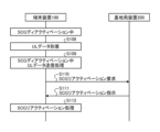
- FIG. 14 is a sequence diagram showing the SCG reactivation operation.
- FIG. 15 is a diagram showing a specific example of mode transition.
- FIG. 16 is a sequence diagram showing RRC message transmission/reception operations during radio bearer suspension.
- FIG. 17 is a sequence diagram showing RRC message transmission/reception operations that control uplink transmission.
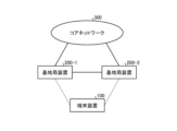
- FIG. 1 is a diagram showing a configuration example of a communication system.
- the communication system shown in FIG. 1 has a terminal device 100, base station devices 200-1 and 200-2, and a core network 300.
- FIG. This communication system may be a wireless communication system in which the terminal device 100 communicates with the base station device 200-1 or the base station device 200-2.
- a wireless communication system that communicates with the station apparatus 200-2 and MR-DC may be used.
- the base station device 200-1 is the master base station device
- the base station device 200-2 is the secondary base station device.
- a master base station apparatus may be called MN (master node: Master Node)
- SN secondary node: Secondary Node
- the terminal device 100 wirelessly connects to one or both of the base station devices 200-1 and 200-2 and performs wireless communication.
- RATs Radio Access Technology
- the terminal device 100 is a tablet terminal or smart phone compatible with one or both of E-UTRA and NR.
- the base station devices 200-1 and 200-2 are wireless communication devices that wirelessly connect with the terminal device 100 and perform wireless communication. Also, the base station apparatuses 200-1 and 200-2 are connected to each other by wire, for example, and communicate with each other.
- the base station device 200 is connected to the core network 300 by wire, for example, and performs communication.
- the base station apparatus 200 corresponds to, for example, eNodeB when E-UTRA is the RAT and gNodeB when the NR is the RAT.
- the core network 300 is a network compatible with any generation of mobile communication systems. That is, the core network 300 is, for example, a core network supporting 5G (hereinafter sometimes referred to as "5GC"), an EPC (Evolved Packet Core) supporting 4G, or the like.
- 5GC core network supporting 5G
- EPC Evolved Packet Core
- FIG. 2 is a block diagram showing a configuration example of the base station apparatus 200.
- the base station device 200 is a communication device or relay device having a processor 210 , a storage 220 , a memory 230 , a wireless communication circuit 240 and a network interface (NI: Network Interface) 250 .
- NI Network Interface
- the storage 220 is an auxiliary storage device such as flash memory, HDD (Hard Disk Drive) or SSD (Solid State Drive) that stores programs and data.
- the storage 220 stores a wireless communication program 221 and a base station side program 222 .
- the memory 230 is an area into which programs stored in the storage 220 are loaded. Also, the memory 230 may be used as an area where programs store data.
- the wireless communication circuit 240 is a circuit that wirelessly connects with the terminal device 100 and performs communication.
- the base station device 200 receives a signal transmitted from the terminal device 100 via the radio communication circuit 240 and transmits the signal to the terminal device 100 .
- the NI 250 is, for example, a communication device that connects with another base station device 200 and realizes inter-base station communication. Also, the NI 250 is a communication device that connects to, for example, the core network 300 (a communication device that configures the core network 300) and performs communication. As the NI 250, for example, a NIC (Network Interface Card) can be used. Base station apparatus 200 receives signals transmitted from other communication apparatuses via NI 250 and transmits signals to other communication apparatuses.
- the processor 210 has, for example, a CPU (Central Processing Unit), etc., loads a program stored in the storage 220 into the memory 230, executes the loaded program, builds each processing unit, and realizes various processes. .
- a CPU Central Processing Unit
- This wireless communication process is a process of wirelessly connecting with the terminal device 100, wirelessly communicating with the terminal device 100, or relaying communication performed by the terminal device 100 with another communication device.
- the processor 210 builds a transmitting unit, a receiving unit and a processing unit by executing the base station side program 222, and performs base station side processing.
- the base station side processing may include MR-DC master node processing and MR-DC secondary node processing.
- the MR-DC master node processing is processing for controlling the master node side in the MR-DC
- the MR-DC secondary node processing is processing for controlling the secondary node side in the MR-DC.
- the base station apparatus 200 performs communication corresponding to each type of MR-DC described later in the MR-DC master node process and the MR-DC secondary node process.
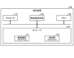
- FIG. 3 is a block diagram showing a configuration example of the terminal device 100.
- Terminal device 100 is a communication device having processor 110 , storage 120 , memory 130 and wireless communication circuit 140 .
- the storage 120 is an auxiliary storage device such as flash memory, HDD or SSD that stores programs and data.
- the storage 120 stores a wireless communication program 121 and a terminal side program 122 .
- the memory 130 is an area into which programs stored in the storage 120 are loaded. In addition, the memory 130 may be used as an area where programs store data.
- the wireless communication circuit 140 is a circuit that wirelessly connects with the base station device 200 and performs communication.
- the terminal device 100 receives a signal transmitted from the base station device 200 via the radio communication circuit 140 and transmits the signal to the base station device 200 .
- the wireless communication circuit 140 for example, a network card that supports wireless connection can be used.
- the processor 110 loads a program stored in the storage 120 into the memory 130, executes the loaded program, constructs each processing unit, and implements various types of processing.
- the processor 110 performs wireless communication processing by executing the wireless communication program 121 .
- This wireless communication processing is processing for wirelessly connecting with the base station device 200 , wirelessly communicating with the base station device 200 , and communicating with other communication devices via the base station device 200 .
- the processor 110 executes the terminal-side program 122 to construct a transmitting unit and a receiving unit processing unit, and performs terminal-side processing.
- the terminal-side processing may include terminal-side MR-DC processing.
- the terminal-side MR-DC processing is processing for controlling communication in the MR-DC.
- the terminal device 100 performs communication corresponding to each type of MR-DC described later in the terminal-side MR-DC processing.
- Protocol stack An example protocol stack for a communication system will be described. In a communication system, a hierarchical structure of a series of protocols for transmitting and receiving data is called a protocol stack. Below, the case where the base station apparatus 200 is eNB or gNB and the core network 300 is EPC or 5GC will be described. Also, it is assumed that the terminal device 100 (UE: User Equipment) supports one or both of E-UTRA and NR.
- UE User Equipment
- the protocol stacks of the U-Plane (User Plane) and C-Plane (Control Plane) are described below.
- the U-Plane corresponds to, for example, a data signal (message) of transmitted/received user data.
- the C-Plane corresponds to, for example, control signals (messages) transmitted and received in communication.
- FIG. 4 is a diagram showing an example of a U-Plane protocol stack when the core network 300 is 5GC.
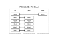
- FIG. 5 is a diagram showing an example of a C-Plane protocol stack when the core network 300 is 5GC.
- SDAP, PDCP, RLC, MAC, PHY, NAS, and RRC in FIGS. 4 and 5 indicate layer names, respectively.
- each of SDAP, PDCP, RLC, MAC, PHY, NAS and RRC may be attached with a sublayer or layer and called, for example, "SDAP sublayer" or "SDAP layer”.
- SDAP, PDCP, RLC, MAC, PHY, NAS and RRC may each be given an entity and called, for example, an "SDAP entity”.
- the U-Plane protocol stack when the core network 300 is EPC is a protocol stack in which SDAP does not exist in FIG. That is, when the core network 300 is EPC, the U-Plane protocol stack consists of PDCP, RLC, MAC and PHY.
- the C-Plane protocol stack when the core network 300 is the EPC has a form in which the NAS shown in FIG. 5 exists in the MME (Mobility Management Entity) instead of the AMF.
- MME Mobility Management Entity
- each layer may or may not be common between the E-UTRA and NR RATs.
- E-UTRA and NR RATs.
- the description is about functions common to E-UTRA and NR.
- the U-Plane is composed of SDAP (Service Data Adaptation Protocol), PDCP (Packet Data Convergence Protocol), RLC (Radio Link Control), MAC (Medium Access Control) and PHY (PHYsical).
- SDAP Service Data Adaptation Protocol
- PDCP Packet Data Convergence Protocol
- RLC Radio Link Control
- MAC Medium Access Control
- PHY PHYsical
- UE and base station apparatus 200 (gNB).
- the PHY is a radio physical layer, and transmits control information and data between the terminal device 100 and the base station device 200 using a physical channel.
- the direction from the base station device 200 to the terminal device 100 may be called a downlink (downlink, DL), and the direction from the terminal device 100 to the base station device 200 may be called an uplink (uplink, UL).
- the PHY is connected to the MAC, which is the upper layer, by a transport channel, and data moves between the PHY and the MAC via the transport channel. .
- MAC is the medium access control layer, mapping transport channels and logical channels (LCH), multiplexing/demultiplexing of MAC SDUs, scheduling reports, error correction through HARQ (Hybrid Automatic Repeat reQuest), priority control, etc. conduct.
- LCH mapping transport channels and logical channels
- HARQ Hybrid Automatic Repeat reQuest
- the MAC is connected to RLC, which is an upper layer, by a logical channel, and data moves between the MAC and the RLC via the logical channel.
- SDU Service Data Unit
- PDU Protocol Data Unit
- RLC, PDCP, and SDAP include PDUs for control, and these PDUs are sometimes called control PDUs.
- Other PDUs may also be referred to as data PDUs to distinguish them from control PDUs.
- RLC is a radio link control layer and has three modes: transparent mode (TM), unacknowledged mode (UM), and acknowledged mode (AM).
- TM RLC is sometimes called TM RLC
- UM RLC is called UM RLC
- AM RLC is called AM RLC.
- RLC on the transmitting side, transfers PDUs of PDCP, which is an upper layer, assigns sequence numbers (in the case of UM or AM), divides data (in the case of UM or AM), and performs re-division (in the case of AM). .
- the RLC performs SDU reassembly (in the case of UM or AM), duplicate detection (in the case of AM), and discarding of RLC SDUs (in the case of UM or AM) on the receiving side.
- RLC performs RLC re-establishment, etc. on the transmitting and receiving sides.
- the RLC also performs data combining on the transmitting side and reordering and in-order delivery on the receiving side.
- Control PDUs used in RLC include, for example, status PDUs.
- the status PDU is used by the receiving side of the AM RLC entity to report to the AM RLC entity, which is the communication partner, about RLC data PDUs that have been successfully received and RLC data PDUs that have not been successfully received (that is, loss has been detected). It is a control PDU to do.
- PDCP is a packet data convergence protocol layer, U-Plane and C-Plane data transfer, PDCP sequence number management, header compression/decompression, encryption/decryption, integrity protection/integrity verification, timer-based SDU It does things like discarding, routing to split bearers, reordering and in-order delivery. Note that for E-UTRA, functions such as timer-based SDU discard, reordering and in-order delivery in PDCP may be limited to split bearers.
- a control PDU used in PDCP includes, for example, a PDCP status report.
- the PDCP status report is sent from the upper layer (RRC layer) to the AM DRB (described later) for which PDCP status report transmission is set, for example, PDCP entity re-establishment or PDCP It is sent in the uplink (UL) direction, such as when data recovery is requested.
- RRC layer the upper layer
- AM DRB the AM DRB
- the PDCP entity re-establishment process includes the following processes. Initialization of state variables in the UM DRB (see below) and SRB (see below) Application of security algorithms and security keys provided by higher layers Sending incomplete and/or successful transmission at the sender Transmission of data that does not exist ⁇ Transmission of PDCP status report (when PDCP status report transmission is set)
- the PDCP data recovery process includes the following processes: - Transmission of data that has not been successfully transmitted on the transmitting side - PDCP status report transmission (when PDCP status report transmission is set)
- SDAP is a service data adaptation protocol layer that maps QoS (Quality of Service) flows to Data Radio Bearers (DRB), and QoS to downlink (DL) and uplink (UL) packets. Marking of the flow identifier (QFI: QoS Flow Identifier) is performed.
- Control PDUs used in SDAP include end marker control PDUs, for example.
- IP Internet Protocol
- TCP Transmission Control Protocol
- UDP User Datagram Protocol
- Ethernet registered trademark
- layers such as IP, TCP, UDP and Ethernet may be included in the PDU layer.
- IMS IP Multimedia Subsystem
- the C-Plane of AS (Access Stratum) is composed of RRC (Radio Resource Control), PDCP, RLC, MAC and PHY, and terminates at terminal device 100 and base station device 200.
- the NAS (Non Access Stratum) C-Plane is composed of NAS and terminates between the terminal device 100 and the AMF (Access and Mobility Management Function), which is a device of the core network 300 .
- PDCP, RLC, MAC and PHY are the same as U-Plane.
- RRC broadcasts system information (SI: System Information) related to AS and NAS, paging, establishment/maintenance/release of RRC connection between terminal device 100 and base station device 200, addition/change of carrier aggregation (CA) /release, dual connectivity (DC) addition/change/release, security functions including security key management, signaling radio bearer (SRB) and data radio bearer (DRB) establishment/configuration/maintenance/release, It performs mobility functions, QoS management functions, control of terminal equipment measurement reports and reporting, radio link failure (RLF) detection and recovery, and NAS message transfer.
- SI System Information
- the NAS performs authentication, mobility management and security control. Note that, as described above, when the device of the core network 300 is the EPC, the NAS terminates between the terminal device 100 and the MME, which is the device of the core network 300 .
- Channels used in communication systems are described. Examples of channels corresponding to NR are shown below, but the channels to be used are not limited to the following. Channels with the same name can also be used for the same or similar purposes in RATs other than NR (eg, E-UTRA).
- Physical channel - A PBCH (Physical Broadcast CHannel) is a channel used to transmit broadcast information from the base station apparatus 200 to the terminal apparatus 100 .
- a PDCCH Physical Downlink Control Channel
- DCI Downlink Control Information
- a PDSCH Physical Downlink Shared CHannel
- a PDSCH is a channel used to transmit data, etc. from an upper layer from the base station device 200 to the terminal device 100 .
- a PUCCH Physical Uplink Control Channel
- UCI Uplink Control Information
- a PUSCH Physical Uplink Shared CHannel
- a PUSCH Physical Uplink Shared CHannel
- a PRACH Physical Random Access Channel
- a PRACH is a channel used to transmit a random access preamble and the like from the terminal device 100 to the base station device 200.
- Transport channel - BCH (Broadcast CHannel) is mapped to PBCH, which is a physical channel.
- DL-SCH DownLink Shared CHannel
- PDSCH DownLink Shared CHannel
- PCH Paging CHannel
- PDSCH Physical channel
- UL-SCH UpLink Shared CHannel
- PUSCH Physical channel
- RACH Random Access CHannel(s)
- PRACH Physical channel
- Logical channel - BCCH Broadcast Control CHannel
- BCCH Broadcast Control CHannel
- PCCH Paging Control CHannel
- CCCH Common Control Channel
- RRC Radio Resource Control Channel
- DCCH Dedicated Control Channel
- DCCH is a point-to-point bi-directional channel that transmits dedicated control information (such as RRC messages) between terminal device 100 and base station device 200, and establishes an RRC connection with base station device 200.
- the downlink is mapped to the transport channel DL-SCH and the uplink is mapped to the transport channel UL-SCH.
- DTCH Dedicated Transport CHannel
- DTCH is a bi-directional channel dedicated to point-to-point terminals and transmits user information (user data). Mapped to the port-channel UL-SCH.
- RRC message The RRC message will be explained.
- An RRC message is a message containing information necessary for communication in a cell, and includes MIB (Master Information Block), SIB (System Information Block), and the like. Parameters included in RRC messages are sometimes referred to as fields or information elements (IEs).
- IEs information elements
- the base station device 200 By transmitting an RRC message to the terminal device 100, the base station device 200 causes the terminal device 100 to execute processing according to the RRC message. In addition, the terminal device 100 receives the RRC message from the base station device 200 and performs processing according to the RRC message. Also, the terminal device 100 requests transmission of the RRC message from the base station device 200 by transmitting the RRC message to the base station device 200 . Also, the terminal device 100 notifies that the processing according to the RRC message received from the base station device 200 has been completed by transmitting the RRC message to the base station device 200 .
- the RRC message includes a message regarding the establishment of an RRC connection.
- messages related to establishment of RRC connection include RRC setup request message (RRCSetupRequest), RRC setup message (RRCSetup), RRC setup completion message (RRCSetupComplete), and the like.
- messages related to establishment of RRC connection include an RRC connection setup request message (RRCConnectionSetupRequest), an RRC connection setup message (RRCConnectionSetup), and an RRC connection setup complete message (RRCConnectionSetupComplete).
- the RRC message also includes a message regarding the initial activation of AS (Access Stratum) security.
- Messages relating to the initial activation of AS security include, for example, security mode command messages (SecurityModeCommand).
- the RRC message includes a message regarding reconfiguration of the RRC connection.
- messages related to RRC connection reconfiguration include an RRC reconfiguration message (RRCReconfiguration) and an RRC reconfiguration complete message (RRCReconfigurationComplete).
- messages related to RRC connection reconfiguration include an RRC connection reconfiguration message (RRCConnectionReconfiguration) and an RRC connection reconfiguration complete message (RRCConnectionReconfigurationComplete).
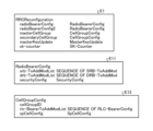
- Figures 6 and 7 are diagrams showing specific examples of the parameters of the RRC message.
- format E1 is the parameters of the RRC reconfiguration message.
- the RRC reconfiguration message has radioBearerConfig, radioBearerConfig2, masterCellGroup, secondaryCellGroup, masterKeyUpdate and sk-counter as parameters.
- radioBearerConfig and radioBearerConfig2 are settings related to MN-terminated bearers or SN-terminated bearers, and include SRB settings, DRB settings, security settings, and the like.
- the SRB setting includes an SRB identifier (DRB identifier), a PDCP setting, a parameter instructing PDCP re-establishment, a parameter instructing PDCP data recovery, and the like.
- the security configuration contains a parameter (keyToUse) that indicates whether to use the master key or the secondary key.
- the PDCP settings also include parameters indicating the primary path when multiple RLCs are associated (for example, in the case of split bearers), parameters for setting PDCP status report transmission, and the like.
- the masterCellGroup and secondaryCellGroup are MCG settings and SCG settings, respectively, and include cell group identifiers, RLC bearer settings, SpCell settings, and the like.
- the RLC bearer setup includes a logical channel identifier, an RLC setup, a radio bearer identifier (SRB identifier or DRB identifier) with which the RLC bearer is associated, and so on.
- SpCell configuration includes information required for reconfiguration with synchronization.
- masterKeyUpdate contains the information necessary to update the master key.
- the sk-counter contains information necessary for secondary key generation.
- Format E11 shown in FIG. 6 is a diagram showing an example of RadioBearerConfig parameters included in the RRC reconfiguration message.
- Format E12 is a diagram showing an example of CellGroupConfig parameters included in the RRC reconfiguration message.
- Format E111 shown in FIG. 7 is a diagram showing an example of parameters of SRB-ToAddMod included in RadioBearerConfig of format E11.
- Format E112 is a diagram showing an example of DRB-ToAddMod parameters included in RadioBearerConfig of format E11.
- Format E113 is a diagram showing an example of SecurityConfig parameters included in RadioBearerConfig of format E11.
- Format E121 shown in FIG. 7 is a diagram showing an example of parameters of RLC-BearerConfig included in CellGroupConfig of format E12.
- Format E122 is a diagram showing an example of parameters of SpCellConfig included in CellGroupConfig of format E12.
- the message regarding reconfiguration of RRC connection establishes, configures, changes or releases radio bearers and cell groups, reconfigures with synchronization, etc., and also establishes, configures, changes or releases measurement information.
- the RRC message includes a message regarding re-establishment of RRC connection, a message regarding release and suspension of RRC connection, a message regarding resumption of RRC connection, a message regarding terminal device capability, a message regarding terminal information, and MCG or SCG failure information. including messages about
- the eNB when the master node is eNB in MR-DC, the eNB includes the NR RRC message and parameters received from the secondary node gNB as a container in the E-UTRA RRC message and transmits it to the terminal device 100.
- the terminal device 100 may be configured for NR.
- the terminal device 100 may include a completion message for the NR setting in an E-UTRA RRC message as a container and transmit the message to the master node eNB.
- gNB when the master node is gNB in MR-DC, gNB includes the E-UTRA RRC message and parameters received from eNB, which is a secondary node, as a container in the NR RRC message and transmits it to the terminal device 100. Accordingly, the terminal device 100 may be configured for E-UTRA. Also, the terminal device 100 may include a completion message for E-UTRA configuration in an NR RRC message as a container and transmit it to the master node gNB.
- Radio Bearer An example radio bearer of a communication system is described.
- signaling radio bearer A signaling radio bearer (SRB) is a radio bearer for transmitting RRC messages and NAS messages.
- SRB0 is the radio bearer for RRC messages using the CCCH logical channel.
- SRB1 is the radio bearer for RRC and NAS messages using the DCCH logical channel before SRB2 is established as described below.
- SRB2 is the radio bearer for NAS and RRC messages containing historically logged measurement information and uses the DCCH logical channel. The priority of SRB2 is lower than that of SRB1 and may be set by base station apparatus 200 after AS security is activated.
- SRB3 is a radio bearer for RRC messages when EN-DC, NGEN-DC or NR-DC is configured in the terminal device 100, and uses the DCCH logical channel. Note that EN-DC, NGEN-DC and NR-DC are types of MR-DC and will be described in detail later.
- DRB data radio bearer
- SRB1 and SRB2 consist of one PDCP and one or more RLC bearers.
- An RLC bearer consists of RLC and MAC logical channels. It is assumed that MAC exists for each cell group described below.
- the RLC mode is AM.
- SRB3 consists of one PDCP and one RLC bearer.
- the RLC mode is AM.
- a DRB consists of one PDCP and one or more RLC bearers.
- the mode of RLC is UM or AM.
- DRB may be called UM DBR when RLC is UM, and AM DRB when RLC is AM.
- DRB is associated with one SDAP when the core network 300 is 5GC, and one EPS (Evolved Packet System) bearer (or EPS bearer identifier (EPS bearer identifier) when the core network 300 is EPC. identifier)).
- EPS Evolved Packet System
- 5GC is a core network standardized for 5G, and is described in, for example, 3GPP standards TS 23.501 and TS 23.502.
- EPC is a core network standardized for 4G, and is described in, for example, 3GPP standards TS 23.401 and TS 23.402.
- a cell group indicates the configuration of a cell in MR-DC.
- cell groups are classified into a master cell group (MCG: Master Cell Group) and a secondary cell group (SCG: Secondary Cell Group).
- FIG. 8 is a diagram showing a configuration example of a cell group of a communication system.
- the master node (MN) is the base station device 200-1
- the secondary node (SN) is the base station device 200-2.
- a master node provides a C-Plane connection to the core network 300 in MR-DC.
- the secondary node does not provide the C-Plane to the core network 300 in MR-DC and provides additional radio resources to the terminal device 100 .
- a CG is composed of one special cell (SpCell: Special Cell), or one SpCell and one or more secondary cells (SCell: Secondary Cell).
- SpCell Special Cell
- SCell Secondary Cell
- the SpCell in the MCG is called a primary cell (PCell)
- the SpCell in the SCG is sometimes called a primary SCG cell (PSCell).
- the MCG is composed of one PCell and two SCells.
- the SCG is composed of one PSCell and two SCells.
- the MCG is the CG when the MR-DC is not configured, or the CG belonging to the master node when the MR-DC is configured.
- SCG is the CG belonging to the secondary node when MR-DC is configured.
- a PCell is a cell that operates on the primary frequency in the MCG and is used for the initial connection establishment procedure or connection re-establishment procedure of the terminal device 100 .
- Connection establishment/re-establishment procedures include random access procedures.
- a PS Cell is a cell used in a random access procedure or the like when the terminal device 100 performs reconfiguration with sync in SCG.
- the SCell is a cell that provides additional radio resources in addition to the SpCell to the terminal device 100 for which carrier aggregation is set.
- MR-DC [Type of MR-DC] The types of MR-DC will be explained. MR-DC is classified into four types according to the type (corresponding generation) of the base station apparatus 200 of the master node and the secondary node and the type (corresponding generation) of the core network 300 .
- FIG. 9 is a diagram explaining the types of MR-DC. Each type of MR-DC will be described below.
- the master node is base station device 200-1
- the secondary node is base station device 200-2.
- thin solid lines indicate U-Plane connections
- dashed lines indicate C-Plane connections
- thick solid lines indicate interfaces between base stations.
- FIG. 9(a) is a diagram showing an example of EN-DC (E-UTRA-NR DC).
- the base station device 200-1 that is the master node is an E-UTRA eNB
- the base station device 200-2 that is a secondary node is an NR gNB
- the core network 300 is an EPC MR-DC. is.
- FIG. 9(b) is a diagram showing an example of NGEN-DC (NG-RAN E-UTRA-NR DC).
- NGEN-DC is an MR-DC in which a master node (base station device 200-1) is eNB, a secondary node (base station device 200-2) is gNB, and core network 300 is 5GC.
- FIG. 9(c) is a diagram showing an example of NE-DC (NR-E-UTRA DC).
- the NE-DC is an MR-DC in which the master node (base station device 200-1) is a gNB, the secondary node (base station device 200-2) is an eNB, and the core network 300 is a 5GC.
- FIG. 9(d) is a diagram showing an example of NR-DC (NR-NR DC).
- NR-DC is an MR-DC in which the master node (base station device 200-1) is a gNB, the secondary node (base station device 200-2) is another gNB, and the core network 300 is 5GC.
- EN-DC and NGEN-DC are sometimes called (NG) EN-DC.
- a secondary node of an EN-DC may be referred to as an en-gNB.
- the master node of NGEN-DC may be called ng-eNB.
- SRB1 and SRB2 are established as C-Plane interfaces between the terminal device 100 and the base station device 200-1.
- split SRB1, split SRB2, or SRB3 part of the C-Plane message may be transmitted and received between the secondary node and the terminal device 100.
- FIG. A part of the C-Plane message received by the secondary node is transmitted to the master node via the inter-base station interface.
- part of the C-Plane message transmitted from the secondary node is transmitted from the master node to the secondary node via the inter-base station interface.
- MR-DC bearer type Bearer types in MR-DC are explained.
- MN-terminated a configuration in which PDCP is terminated at the master node and PDCP is provided on the master node side
- SN-terminated a configuration in which PDCP is terminated at a secondary node and PDCP is provided on the secondary node side
- Bearer types are classified into the following six types.
- A MN-terminated MCG bearer in which the RLC bearer exists on the MCG side
- B MN-terminated Split bearer in which the RLC bearer exists in both MCG and SCG
- C MN-terminated
- D SN-terminated
- MCG bearer where the RLC bearer exists on the MCG side
- E An SN-terminated split bearer where the RLC bearer exists on both MCG and SCG
- F SCG bearer with SN-terminated and RLC bearer present on SCG side
- the DRB consists of one of the above six types of bearer types.
- SRB1 and SRB2 are composed of MN-terminated MCG bearers (above (A)) or MN-terminated Split bearers (above (B)).
- SRB1 and SRB2 may be referred to as Split SBR1 and Split SBR2, respectively, when they are composed of MN-terminated Split bearers.
- SBR3 consists of SN-Terminated SCG bearers ((F) above).
- a primary path is set.
- the primary path indicates the base station apparatus 200 to which the terminal apparatus 100 initially (preferentially) transmits data.
- the primary path is designated by cell group (MCG or SCG) and LCH.
- MCG or SCG cell group
- LCH LCH
- the terminal device 100 transmits data to the base station device 200 on the primary path unless the transmission data amount of uplink data exceeds a predetermined threshold.
- the terminal device 100 may transmit data to either base station device 200 when the amount of transmission data exceeds a predetermined threshold.
- the security key used in PDCP differs between MN-Terminated (master key) and SN-Terminated (secondary key).
- Reconfiguration with Sync is a parameter for performing reconfiguration with synchronization (reconfigurationWithSync: hereinafter referred to as "reconfiguration parameter with synchronization") in an RRC reconfiguration message that the base station apparatus 200 transmits to the terminal device 100.
- RRC reconfiguration message that the base station apparatus 200 transmits to the terminal device 100.
- FIG. 10 is a diagram explaining resetting with synchronization.
- the terminal device (UE) 100 changes the connected PCell from the current source PCell to the target PCell (step S1).
- Synchronous reconfiguration parameters are parameters for MCG configuration (hereinafter sometimes referred to as "MCG configuration parameters") or parameters for SCG configuration (hereinafter sometimes referred to as "SCG configuration parameters"). included. That is, if the reset parameter with synchronization is included in the MCG configuration parameters, the reset with synchronization of the MCG is performed, and if the reset parameter with synchronization is included in the SCG configuration parameters, the reset with synchronization of the SCG is executed.
- Reconfiguration with synchronization is a procedure in which the terminal device 100 changes the PCell or PSCell, random access to the new (change destination, target) PCell or PSCell, MAC reset and PDCP data recovery (in the case of AM DRB) including actions such as Reconfiguration with synchronization may also involve changing security keys.
- PDCP entity re-establishment is performed in addition to the above operations.
- PDCP entity re-establishment may be referred to as PDCP re-establishment.
- a QoS flow is a Service Data Flow (SDF) with the same QoS requirements and is identified by a QoS Flow Identifier (QFI).
- the SDF is, for example, an IP flow or an Ethernet flow, and differs depending on upper layers.
- FIG. 11 is a diagram explaining transmission of the end marker control PDU.
- the DRB associated with QoS flow 1 is changed from DRB1 to DRB2 (step S2).
- the terminal device 100 transmits the data of the QoS flow 1 that remains before the change is instructed, using DRB1 before the change.
- the terminal device 100 transmits, via DRB1, an end marker control PDU indicating that data of QoS flow 1 is to be transmitted last via DRB1.
- the association between the QoS flow and the DRB may be performed by parameters included in the RRC reconfiguration message or may be performed by header information included in the downlink SDAP data PDU. The latter is called reflective mapping.
- RRC state (mode) The RRC state of the terminal device 100 indicates the state regarding the RRC connection of the terminal device 100 .
- a state in which an RRC connection with the base station apparatus 200 is not established may be called an RRC idle mode (RRC_IDLE).
- a state in which an RRC connection is established with the base station apparatus 200 may be called an RRC connected mode (RRC_CONNECTED).
- RRC_CONNECTED A state in which the RRC connection with the base station apparatus 200 is temporarily stopped (suspended) may be called an RRC inactive mode (RRC_INACTIVE).
- RRC_INACTIVE RRC inactive mode
- a transition from the RRC idle mode to the RRC connected mode may be performed by transmitting/receiving a message regarding establishment of an RRC connection between the terminal device 100 and the base station device 200 .
- the terminal device 100 sends an RRC setup request message to the base station device 200 and receives an RRC setup message from the base station device 200 as a response, whereby the terminal device 100 may transition to the RRC connection mode.
- the RRC SETUP REQUEST message and the RRC SETUP message may be transmitted and received using the CCCH logical channel.
- the cell used for transmitting and receiving the RRC setup request message and the RRC setup message may be the PCell.
- the terminal device 100 that has transitioned to the RRC connection mode further receives a message regarding the initial activation of AS security and a message regarding re-establishment of the RRC connection from the base station device 200, and by performing settings according to the message, user data (for example, IP packets, Ethernet frames, etc.) can be transmitted and received.
- user data For example, IP packets, Ethernet frames, etc.
- carrier aggregation and MR-DC may be configured by a message regarding re-establishment of RRC connection. It should be noted that messages regarding initial activation of AS security and messages regarding re-establishment of RRC connection may be transmitted and received using the DCCH logical channel.
- a transition from the RRC connected mode to the RRC inactive mode may be performed by the terminal device 100 transmitting/receiving from the base station device 200 a message regarding release of the RRC connection, which includes parameters regarding the suspend setting of the RRC connection.
- FIG. 15A shows a transition procedure (procedure) from RRC connected mode to RRC inactive mode when base station device 200 is gNB (master node is gNB in case of MR-DC) and core network 300 is 5GC.
- FIG. 10 shows.
- the base station apparatus 200 sends to the terminal apparatus 100 a message (RRCRelease) regarding release of the RRC connection including a parameter (suspendConfig) regarding the suspend setting of the RRC connection.
- the terminal device 100 transitions to the RRC inactive mode by performing processing according to the received RRC release message. Note that the RRC Release message can be sent using the DCCH logical channel.
- the terminal device 100 may perform processing including saving the UE inactive AS context and suspending radio bearers other than SRB0.
- the UE inactive AS context includes the current (immediately before transition to RRC inactive mode) security key of the terminal device 100, the state related to header compression, the correspondence between the QoS flow and the DRB, the C in the source (handover source) PCell. - Settings including RNTI (Cell Radio Network Temporary Identifier), etc.
- MR-DC is configured in the terminal device 100
- the configuration regarding SCG may be saved as the UE inactive AS context. Note that some of the parameters related to handover such as reconfiguration with synchronization, some of the parameters set in the SIB, and the like may be excluded from the settings saved as the UE inactive AS context.
- a transition from the RRC inactive mode to the RRC connected mode may be performed by transmitting/receiving a message regarding RRC connection resumption between the terminal device 100 and the base station device 200 .
- FIG. 15(b) shows a transition procedure (procedure) from RRC inactive mode to RRC connected mode when base station device 200 is gNB (master node is gNB in case of MR-DC) and core network 300 is 5GC. It is a diagram.
- the terminal device 100 sends an RRC resume request message (RRCResumeRequest) to the base station device 200, receives an RRC resume message (RRCResume) from the base station device 200 in response, and performs processing according to the received RRC resume message.
- RRCResumeRequest RRC resume request message
- RRCResume RRC resume message
- the terminal device 100 may transition to the RRC connected mode.
- the base station device 200 includes the SCG setting in the RRC restart message, and the SCG Configuration may include reconfiguration with synchronization of the SCG.
- the RRC restart request message is transmitted using, for example, the CCCH logical channel.
- the RRC Resume message is transmitted using, for example, the DCCH logical channel.
- SCG failure information When the terminal device 100 detects an SCG failure when MR-DC is configured, the terminal device 100 may send a message (SCGFailureInformation) regarding SCG failure information to the master node via the MCG.
- SCG failure is, for example, when physical layer synchronization is lost on the SCG side, when random access failure occurs on the SCG side, when the number of RLC retransmissions on the SCG side exceeds a predetermined threshold, and when reconfiguration with synchronization of the SCG fails. It may be detected when the SCG settings cannot be processed, when the integrity verification of the SRB3 fails, and so on.
- the terminal device 100 may perform operations including suspending SCG transmissions for all radio bearers, i.e. suspending transmission of all radio bearers associated with the SCG.
- SCGFailureInformationNR may be sent instead of SCGFailureInformation.
- SCGFailureInformation and SCGFailureInformationNR are transmitted using, for example, the DCCH logical channel.
- the base station apparatus 200 that has received the message regarding the SCG failure information from the terminal device 100 may transmit a message regarding reconfiguration of the RRC connection to the terminal device 100 in order to reconfigure the SCG.
- SCG inactive In EN-DC or NR-DC, the communication between the secondary node and the terminal device 100 may be restricted by deactivating the SCG set in the terminal device 100 .
- SCG deactivation the state in which the SCG is in an inactive state
- SCG being in an active state also referred to as “activation state” or “activation state”
- SCG deactivation the SCG being in an active state
- SCG deactivation activating an inactive SCG
- activating an inactive SCG may be referred to as SCG (re)activation.
- “reactivation” and “reactivate” shall include “activation” and "activate” respectively.
- the terminal device 100 during SCG deactivation shall satisfy some or all of the following conditions. - When a message (for example, an RRC reconfiguration message) related to reconfiguration of the SCG RRC connection is received from the base station apparatus 200, the processing according to this message is executed. - Uplink transmission on the SCG side is not performed. Processing for uplink data may be performed - PDCCH monitoring (reception) is not performed in PSCell - PUSCH transmission on the SCG side is not performed
- the terminal device 100 includes a parameter indicating SCG deactivation in the message regarding reconfiguration of the RRC connection received from the base station device 200 and includes a parameter regarding reconfiguration with synchronization of SCG does not perform random access processing at least in the SCG.
- terminal device 100 during SCG deactivation may communicate with the base station device 200 in the RRC connection mode using MCG.
- Embodiment 1 will be described.
- the communication system switches from SCG deactivation to SCG (re)activation, or from SCG (re)activation to SCG deactivation.
- Appropriate control means, for example, to control unnecessary switching so as not to perform unnecessary switching, or to postpone switching timing until necessary timing, in order to achieve power saving.
- the communication system controls unnecessary uplink transmission during SCG deactivation to save power.
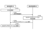
- FIG. 12 is a sequence diagram showing a transition operation to SCG deactivation.
- Base station apparatus 200 is, for example, a master node in MR-DC.
- MR-DC in FIG. 12 includes, for example, (NG)EN-DC and NR-DC.
- NG NGEN-DC
- NR-DC NR-DC
- the message transmitted/received by the base station apparatus 200 may be transmitted/received by either the master node or the secondary node.
- the message transmitted from the terminal device 100 to the secondary node shall be transmitted to the master node via inter-base station communication.
- the processing executed by the base station apparatus 200 may be executed by either the master node or the secondary node.
- the terminal device 100 does not transmit a message to the secondary node and does not receive PDCCH from the secondary node during SCG deactivation.
- the terminal device 100 sets the SCG (step S101) and is in SCG (re)activation.
- the SCG setting is performed by the terminal device 100 receiving an RRC reconfiguration message including SCG setting parameters from the base station device 200 .
- the SGC setting parameters include, for example, NR SGC setting parameters.
- the terminal device 100 transmits a terminal information notification to the base station device 200 (step S102).
- the terminal information notification is, for example, an RRC message or a parameter included in the RRC message.
- the terminal information notification may be, for example, UE assistance information in an RRC message, or may be a message with another name.
- the terminal information notification includes, for example, information indicating whether power saving is required in the terminal device 100 .
- the terminal device 100 determines whether power saving is necessary, for example, according to the remaining battery level.
- the terminal information notification includes, for example, information indicating whether SCG deactivation (or SCG release) is necessary.
- the terminal device 100 determines the necessity of SCG deactivation, for example, according to the amount of communication (data communication amount) with the secondary node.
- information indicating whether to immediately perform may contain
- the terminal information notification is, for example, when UL data occurs, without permission of the base station device 200 (without transmitting an SCG reactivation request in step S110 described later), SCG (re)activation It may also contain information indicating that it will be executed. This makes it possible to omit part of message transmission/reception between the base station apparatus 200 and the terminal apparatus 100 in SCG (re)activation.
- the base station apparatus 200 Upon receiving the terminal information notification, the base station apparatus 200 performs SCG deactivation determination processing (step S103). Note that the base station apparatus 200 performs SCG deactivation determination processing when an event requiring (or possibly requiring) SCG deactivation occurs in addition to when the terminal information notification is received. Execute.
- the SCG deactivation determination process is a process of determining whether or not to perform SCG deactivation on the terminal device 100.
- the base station device 200 determines whether or not SCG deactivation is to be performed using, for example, the amount of communication between the terminal device 100 and the secondary node.
- the base station apparatus 200 operates as a secondary node when, for example, the amount of communication between the terminal apparatus 100 and the secondary node is less than or equal to a predetermined value during a predetermined period of time, or when communication between the terminal apparatus 100 and the secondary node does not occur for a predetermined period of time.
- the amount of communication using is small, it is determined to perform SCG deactivation.
- the base station device 200 determines whether or not there is SCG deactivation using, for example, the allocatable radio resource amount of the secondary node.
- the base station device 200 determines to perform SCG deactivation, for example, when the amount of available radio resources in the secondary node is equal to or less than a predetermined value.
- the base station device 200 When the base station device 200 determines to perform SCG deactivation in the SCG deactivation determination process, it transmits an SCG deactivation instruction to the terminal device 100 (step S104).
- the SCG deactivation indication may be, for example, an RRC message or a parameter included in the RRC message.
- the SCG deactivation instruction may be a parameter included in the RRC reconfiguration message, may be a parameter included in the RRC resume message, or may be a parameter included in the RRC connection reconfiguration message. However, it may be a parameter included in a message with another name.
- the SCG deactivation instruction may be a parameter that instructs the terminal device 100 to perform SCG deactivation.
- the SCG deactivation instruction may be a parameter indicating that the SCG of the terminal device 100 is in a deactivated state.
- the SCG deactivation indication may be a parameter such as scg-state.
- the SCG deactivation instruction immediately executes part or all of the SCG reconfiguration with synchronization. Includes information on whether or not When the information to the effect that all processing is to be executed immediately is included, the terminal device 100 immediately executes reconfiguration with synchronization of the SCG. Also, if information is included to the effect that some or all of them will not be immediately executed, the terminal device 100, when executing the SCG (re)activation later, performs the unexecuted reset processing with synchronization of the SCG. Execute (suspend reset with synchronization), or do not execute some or all of the reset with synchronization of SCG (discard some or all of instructions (parameters) for reset with synchronization) ).
- the SCG deactivation instruction is, for example, when the terminal device 100 is instructed to perform reconfiguration with synchronization of SCG during SCG deactivation, if at least the first condition is not met, synchronization of SCG immediately Information to the effect of instructing to execute part or all of the tag resetting process may be included. In this case, if the terminal device 100 does not meet at least the first condition, the terminal device 100 immediately performs reconfiguration with synchronization of the SCG. Further, in this case, when at least the first condition is met, the terminal device 100 executes the unexecuted one of the SCG resetting processes with synchronization when executing the SCG (re)activation later. (suspend reset with synchronization), or do not execute some or all of the reset with synchronization processing of SCG (discard some or all of instructions (parameters) for reset with synchronization) ).
- the first condition is, for example, to satisfy some or all of the following (Conditions 1-1) to (Conditions 1-4).
- SCG reconfiguration with synchronization is accompanied by a change in the master node's security key (KgNB or KeNB) or a change in the AS security key generated from the master node's security key.
- KgNB or KeNB master node's security key
- a radio bearer that uses a master key may be a radio bearer whose parameter (keyToUse) indicating whether to use the master key or the secondary key is set to master (or primary).
- a radio bearer using a secondary key may be a radio bearer whose parameter (keyToUse) indicating whether to use the master key or the secondary key is set to secondary.
- the terminal device 100 does not immediately execute part or all of the reconfiguration processing with synchronization of the SCG, communication in MR-DC (especially using the master node communication). Thereby, since the terminal device 100 does not perform unnecessary SCG (re)activation, power consumption can be suppressed.
- the SCG deactivation instruction is information to the effect that, for example, when the terminal device 100 is instructed to perform SCG reconfiguration with synchronization during SCG deactivation, it immediately performs SCG reconfiguration with synchronization.
- the SCG deactivation instruction may include information to the effect that, for example, when UL data is generated, SCG (re)activation is instructed without the permission of the base station device 200. In this case, the terminal device 100 immediately executes SCG (re)activation.
- the terminal device 100 Upon receiving the SCG deactivation instruction, the terminal device 100 performs SCG deactivation processing (step S105).
- the SCG deactivation process is a process of transitioning to SCG deactivation. Note that the terminal device 100 may determine that it is necessary to perform the SCG deactivation process by receiving the SCG deactivation instruction, and perform the SCG deactivation process. Moreover, the terminal device 100 may determine that there is no need to perform the SCG deactivation process by not receiving the SCG deactivation instruction, and may not perform the SCG deactivation process.
- the SCG deactivation process may include some or all of the following (1) to (3) processes.
- (1) Consider that the SCG is deactivated (2) Notify the lower layer that the SCG has been deactivated (3)
- RRC If in connected mode or RRC inactive mode, trigger SDU discard to PDCP entity in SRB3 and/or re-establish RLC entity in SRB3
- the lower layer may be the MAC layer, the RLC layer, or the PDCP layer. Further, the processing of (3) above may be performed when SRB3 is set in the terminal device 100 and SRB3 is not released by an RRC message including an SCG deactivation instruction.
- the terminal device 100 may continue the SCG deactivation state.
- the terminal device 100 receives an RRC reconfiguration message that does not include an SCG deactivation instruction during SCG deactivation, an RRC connection reconfiguration message that does not include an SCG deactivation instruction, or an RRC that does not include an SCG deactivation instruction.
- the resume message it may be determined that the SCG (re)activation process should be performed, and the SCG (re)activation process may be performed.
- the SCG (re)activation process may include some or all of the following processes (4) to (5). (4) SCG is considered to be (re)activated (5) If the terminal device 100 is in SCG deactivation, notify the lower layer that the SCG has been (re)activated
- the lower layer may be the MAC layer, the RLC layer, or the PDCP layer.
- the terminal device 100 stops some or all of the timers running for SCG. Also, the terminal device 100 resets some or all of the counters set in the SCG. Also, the terminal device 100 resets the SCG MAC. Furthermore, the terminal device 100 performs the second process on radio bearers that satisfy at least the second condition.
- the second condition is that it is an SCG bearer, that it is a split bearer, or that it is a split bearer and the primary path is set to the SCG.
- the radio bearers that satisfy the second condition may be, for example, some or all of the radio bearers set in the terminal device 100 .
- timers activated for the SCG to be stopped may include a timer for detecting radio link failure (RLF) of the SCG.
- timers activated for the SCG to be stopped may include a timer for the measurement report of the SCG.
- the counters set in the SCG to be reset may include a counter for detecting Radio Link Failure (RLF) of the SCG.
- to perform the second processing for radio bearers that satisfy at least the second condition means that the terminal device 100 determines whether or not at least the second condition is satisfied for each radio bearer, and performs at least the second condition. , the second process may be performed on this radio bearer.
- to perform the second processing for radio bearers that satisfy at least the second condition means that the terminal device 100 determines whether or not at least the second condition is satisfied for each radio bearer, and performs at least the second condition. If it is determined that the above conditions are satisfied and it is further determined that it is necessary to perform the second processing on this radio bearer, the second processing may be performed on this radio bearer.
- the second condition "being an SCG bearer” means that one or both of a parameter (moreThanOneRLC) meaning one or more RLCs and a parameter (primaryPath) meaning a primary path are set in the radio bearer (PDCP). and that the RLC bearer of the radio bearer is in the SCG. Also, the second condition "being an SCG bearer” may be that the RLC bearer of the radio bearer exists only in the SCG. This "radio bearer's RLC bearer" may be the RLC bearer associated with the radio bearer.
- the second condition, ⁇ split bearer and the primary path is set in the SCG'' is that the primary path (or the parameter meaning the primary path) of the radio bearer (PDCP) is set in the SCG. (or refer to SCG).
- the second process is a process performed on some or all radio bearers that satisfy at least the second condition.
- the second process is part or all of the process when transitioning to SCG deactivation and the pre-process.
- the second processing includes, for example, some or all of the following processing.
- some or all of the radio bearers that satisfy at least the second condition may be referred to as second radio bearers.
- the reordering timer is activated in the PDCP of the second radio bearer If so, stop and send all stored PDCP SDUs to upper layers in order after header decompression. Re-establish RLC on second radio bearer.
- the second process may be performed according to the following procedure, or may include the following procedure.
- a PDCP SDU that has been given a sequence number but has not been handed over to the lower layer is treated as a PDCP SDU that has just been received from the upper layer. and transmit in order. Also, at this time, the discard timer does not have to be restarted.
- PDCP SDUs for which successful transmission has not been confirmed from the lower layer and/or transmit in order PDCP SDUs that have been assigned sequence numbers but have not been delivered to lower layers.
- the discard timer does not have to be restarted.
- the discard timer may be a timer that is used to discard the corresponding PDCP SDU when it expires.
- the RRC of the terminal device 100 makes a second notification to the PDCP of some or all radio bearers that are SCG bearers or split bearers.
- PDCP may be replaced by lower layer(s).
- PDCP that has received the second notification is an SCG bearer (if there is one associated RLC) or a split bearer (two or more associated RLCs), and the primary path is set on the SCG side If so, the second process is performed.
- the RRC of the terminal device 100 makes a second notification to the PDCP of the second radio bearer.
- PDCP may be replaced by lower layer(s).
- the PDCP that has received the second notification performs a second process.
- Some radio bearers that meet at least the second condition may be, for example, SRBs that meet at least the second condition, or DRBs that meet at least the second condition.
- the second notification is, for example, a notification instructing the discarding of PDCP data.
- the second notification may be a notification instructing to immediately transmit data that has not been completely transmitted.
- the second notification may include information indicating that the SCG is deactivated, such as SCG deactivated or CG UL transmission prohibited (suspended).
- the second notification may contain some or all of these pieces of information.
- the second notification may be multiple messages containing some of these pieces of information.
- the terminal device 100 can suppress unnecessary SCG (re)activation and power consumption.
- the RRC of the terminal device 100 transmits the second information to the SDAP associated with the DRB among the second radio bearers.
- the second information indicates that uplink transmission is not possible on the DRB, such as that UL transmission of the DRB is prohibited (or stopped) or that the cell group to which the DRB is associated is being deactivated. This is the information shown.
- the second information may be sent to the SDAP together with some or all of the following information. Also, the second information may be part or all of the following information. ⁇ DRB identifier of the relevant DRB - the QoS flow identifier associated with that DRB
- transmitting the second information to the SDAP associated with the DRB among the second radio bearers means that the terminal device 100 determines whether or not at least the second condition is satisfied for each DRB, and determines whether or not at least the second condition is satisfied. If it is determined that the condition is met, the DRB may transmit the second information to the associated SDAP.
- transmitting the second information to the SDAP associated with the DRB among the second radio bearers means that the terminal device 100 determines whether or not at least the second condition is satisfied for each DRB, and determines whether or not at least the second condition is satisfied. If it is determined that the condition is satisfied and it is necessary to transmit the second information to the SDAP associated with this DRB, the second information is transmitted to the SDAP associated with this DRB. It can be.
- the second information transmission process may be executed when at least the DRB that satisfies the second condition is associated with SDAP (if SDAP entity associated with this DRB is configured).
- the terminal device 100 may determine whether or not each DRB is related to SDAP, and if it is determined to be related to SDAP, may determine whether or not this DRB satisfies at least the second condition. .
- the terminal device 100 determines whether or not at least the second condition is satisfied for each DRB, and when determining that at least the second condition is satisfied, the terminal device 100 determines whether or not this DRB is related to SDAP. can be
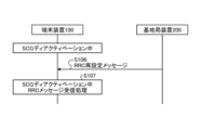
- FIG. 13 is a sequence diagram showing the RRC message transmission/reception operation of the terminal device 100 during SCG deactivation.
- the base station device 200 transmits an RRC reconfiguration message (first message) to the terminal device 100 during SCG deactivation (step S106).
- transmitting an RRC reconfiguration message to the terminal device 100 during SCG deactivation means that the RRC reconfiguration message including a parameter (SCG deactivation instruction) instructing the SCG to be in a deactivation state to the terminal device 100 .
- the state of the SCG of the terminal device 100 may be activated or deactivated.
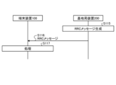
- the RRC reconfiguration message is an RRC message related to RRC connection reconfiguration sent from the base station apparatus 200 to the terminal device 100, and includes establishment, configuration, change and release of radio bearers, cell groups, measurement information and the like, and synchronization. Reconfigure the attachment, etc.
- the RRC reconfiguration message may be, for example, the RRC message RRCReconfiguration, or may be a message with another name.
- the base station apparatus 200 determines that it is necessary to change the settings of the terminal apparatus 100 (change the settings in the RRC connection mode), it generates an RRC reconfiguration message and transmits it to the terminal apparatus 100 .
- the base station apparatus 200 determines that it is necessary to change the settings of the terminal apparatus 100 when MGC handover becomes necessary, for example. Also, for example, when the security key needs to be changed, the base station apparatus 200 determines that the setting of the terminal apparatus 100 needs to be changed. The base station device 200 needs to change the setting of the terminal device 100 when it is necessary to re-establish PDCP (using a key generated from the security key) related to the security key that needs to be changed. judge that it has happened. Also, the base station apparatus 200 needs to change the setting of the terminal apparatus 100, for example, when it is necessary to change the QoS flow to DRB mapping rule (rule indicating the correspondence (map) between the QoS flow and the DRB). I judge.
- DRB mapping rule rule indicating the correspondence (map) between the QoS flow and the DRB
- the RRC reconfiguration message includes, for example, the following information. ⁇ Information instructing to perform reconfiguration with synchronization of SCG ⁇ When information instructing to perform reconfiguration with synchronization of SCG is included, if at least the first condition is not met, immediately perform reconfiguration with synchronization of SCG.
- the first condition is the first condition used in step S103. That is, the first condition is, for example, to satisfy some or all of the above (conditions 1-1) to (conditions 1-4).
- the parameter meaning the SCG configuration (for example, the name secondaryCellGroup) is added to the RRC reconfiguration message. May not include reconfiguration parameters with synchronization (may not require reconfiguration with synchronization of SCG).
- the base station device 200 when the terminal device 100 is in SCG deactivation, the base station device 200 optionally includes a reconfiguration parameter with SCG synchronization in the RRC reconfiguration message to the terminal device 100 (not essential). You can judge. For example, the base station device 200 needs to update the security key of the secondary node, but the terminal device 100 is in SCG deactivation and there is no MN terminated RLC bearer (related to the master key) on the SCG side If so, do not include the reconfiguration with synchronization parameters of the SCG in the RRC reconfiguration message.
- the base station device 200 when the base station device 200 satisfies at least the third condition and the terminal device 100 is not in SCG deactivation, it is essential to include a reconfiguration parameter with SCG synchronization in the RRC reconfiguration message to the terminal device 100. , and the reconfiguration parameter with synchronization of SCG may be included without fail. Further, even when at least the third condition is satisfied, the base station apparatus 200, when the terminal apparatus 100 is in SCG deactivation, reconfigures with SCG synchronization in the RRC reconfiguration message to the terminal apparatus 100. It may be determined that the inclusion of configuration parameters is optional (not mandatory) and the reconfiguration parameters with synchronization of the SCG may not be included.
- the third condition may be, for example, that the AS security key generated from the secondary node security key (S-KgNB or S-KeNB) in NR-DC is changed, or that the secondary key is used1
- the radio bearer described above may be set in the terminal device 100, and may not be released even if the radio bearer performs the process associated with the reception of the RRC reconfiguration request.
- the third condition may be, for example, that the base station apparatus 200 executes MN handover in (NG) EN-DC. Also, the third condition may be, for example, that the base station apparatus 200 performs SCG (re)activation.
- the base station apparatus 200 includes a change of the AS security key generated from the security key (KgNB or KeNB) of the master node in the RRC reconfiguration message to the terminal device 100, and includes the reconfiguration parameter with synchronization of the SCG. Otherwise, if the terminal device 100 is not in SCG deactivation, it may be determined to release all existing SCG RLC bearers associated with radio bearers using the master key.
- KgNB or KeNB security key
- the base station apparatus 200 includes a change of the AS security key generated from the security key (KgNB or KeNB) of the master node in the RRC reconfiguration message to the terminal device 100, and includes the reconfiguration parameter with synchronization of the SCG. If not included, if the terminal device 100 is in SCG deactivation, it may be determined that all existing SCG RLC bearers associated with radio bearers that use the master key need not be released.
- the base station apparatus 200 may include in the RRC reconfiguration message a parameter for instructing to perform SCG reconfiguration with synchronization and a parameter for instructing to perform SCG deactivation.
- a radio bearer that uses a master key may be a radio bearer whose parameter (keyToUse) indicating whether to use the master key or the secondary key is set to master (or primary).
- a radio bearer using a secondary key may be a radio bearer whose parameter (keyToUse) indicating whether to use the master key or the secondary key is set to secondary.
- the terminal device 100 Upon receiving the RRC reconfiguration message, the terminal device 100 performs RRC message reception processing during SCG deactivation (step S107). The terminal device 100 performs processing according to information (parameters) included in the RRC reconfiguration message in the RRC message reception processing during SCG deactivation.
- the RRC reconfiguration message includes, for example, the following parameters. ⁇ Synchronous reset parameter (indicates that resetting with synchronization is to be executed) ⁇ Parameter for instructing PDCP re-establishment (indicating that execution of PDCP re-establishment is instructed) ⁇ Parameters that indicate the setting of the QoS flow to DRB mapping rule (indicate that the execution of resetting of the QoS flow to DRB mapping rule is instructed)
- the terminal device 100 satisfies a predetermined condition, and if the SCG side radio bearer is suspended, uplink communication of the suspended SCG side radio bearer is performed. resume.
- the predetermined condition is, for example, not during SCG deactivation. It should be noted that "when a predetermined condition is satisfied" may be rephrased as "when it is determined whether or not a predetermined condition is satisfied, and when it is determined that the predetermined condition is satisfied”.
- the predetermined condition may be, for example, any one of (Condition 2-1) to (Condition 2-3) below.
- the terminal device 100 when the terminal device 100 is in SCG deactivation, the SCG side radio bearer is not in a suspended state but in another state (for example, SCG is deactivated or uplink transmission is prohibited).
- the terminal device 100 may resume uplink communication of the suspended SCG side radio bearer regardless of whether SCG deactivation is in progress.
- the terminal device 100 may perform the following processing. - The terminal device 100 may immediately execute the reconfiguration process with synchronization of the SCG
- the terminal device 100 does not immediately execute a part or all of the processing of resetting with synchronization of the SCG, and the processing that is not executed immediately may be executed at the time of SCG (re)activation.
- the processing to be executed immediately includes, for example, MAC reset on the SCG side, applying the identifier of the new terminal device 100 as the C-RNTI of the cell group, and the like.
- the processing to be executed during SCG (re)activation is, for example, random access processing on the SCG side (which may include processing for setting the lower layer according to the received parameter (SpCellConfigCommon) meaning the common SpCell configuration), For example, starting a timer to detect reconfiguration failure with synchronization.
- the terminal device 100 determines whether or not to immediately perform the SCG reconfiguration process with synchronization, the SCG deactivation instruction in step S104, or the parameter (SCG reconfiguration with synchronization) included in the RRC reconfiguration message in step S106. parameter) indicating whether to immediately execute the setting. For example, if the terminal device 100 does not meet at least the first condition, it immediately executes the processing of resetting with synchronization of SCG, and if applicable, the processing of resetting with synchronization of SCG is SCG (re)activation. may be executed when Furthermore, the terminal device 100 may return to SCG deactivation again after executing the above-described processing.
- the first condition is the first condition used in step S103. That is, the first condition is, for example, to satisfy some or all of the above (conditions 1-1) to (conditions 1-4).
- the terminal device 100 If it contains a parameter that indicates PDCP re-establishment- When the received RRC reconfiguration message includes a parameter instructing PDCP re-establishment, the terminal device 100 immediately re-establishes PDCP, for example. In this case, if there is data that has not been completely transmitted in the PDCP of some or all of the radio bearers that satisfy at least the second condition, the terminal device 100 transmits the data after the SCG is (re)activated. You can send it.
- the terminal device 100 may perform PDCP re-establishment of some or all radio bearers that satisfy at least the second condition after the SCG is (re)activated.
- PDCP which performs PDCP re-establishment after SCG (re)activation, does not perform processing corresponding to the PDCP SDU even if it receives the PDCP SDU from the upper layer.
- the second condition may be the second condition used in step S105, that is, the SCG bearer, or the split bearer and the primary path is set to the SCG.
- the terminal device 100 receives a PDCP SDU that has been assigned a sequence number but has not been delivered to the lower layer from the upper layer. Regard it as the PDCP SDU just received and send it in order. At this time, it is not necessary to restart the discard timer.
- the terminal device 100 does not confirm successful transmission from the lower layer, for example, in the case of AM DRB or in the case of AM DRB in which the PDCP entity is not suspended.
- PDCP SDUs, and PDCP SDUs that have sequence numbers assigned but have not been handed over to lower layers, are sent in order.
- the terminal device 100 for example, in the case of AM DRB for the Uu interface where the PDCP entity is suspended, PDCP SDUs for which successful transmission has not been confirmed from the lower layer , and PDCP SDUs that have been assigned sequence numbers but have not been delivered to the lower layer are regarded as PDCP SDUs that have just been received from the upper layer, and are transmitted in order. At this time, it is not necessary to restart the discard timer.
- the discard timer may be a timer that is used to discard the applicable PDCP SDU when it expires.
- the base station apparatus 200 immediately performs PDCP re-establishment processing for some or all radio bearers that satisfy at least the second condition in the RRC reconfiguration message in step S106 (or after the SCG is (re)activated may include a parameter indicating what to do).
- the terminal device 100 determines from the parameter whether to immediately perform re-establishment processing for PDCP for some or all radio bearers that satisfy at least the second condition, or to perform after the SCG is (re)activated. good.
- terminal device 100 performs the following processing.
- the QoS flow to DRB mapping rule indicates, for example, the correspondence relationship between QoS flows and DRBs.
- the terminal device 100 performs end marker processing when a predetermined condition is satisfied.
- End marker processing is processing to build an end marker control PDU, map it to the DRB before change, and send it to the lower layer. It should be noted that "when a predetermined condition is satisfied” may be rephrased as "when it is determined whether or not a predetermined condition is satisfied, and when it is determined that the predetermined condition is satisfied.”
- mappedQoS-FlowToAdd included in the received RRC reconfiguration message is assumed to be a parameter for the first QoS flow.
- the DRB ( That is, when the already stored DRB corresponding to the first QoS flow is a DRB that does not correspond to the second information received from the RRC of the terminal device 100 in step S105, end marker processing is performed.
- step S105 the second information is notified to the SDAP associated with at least the data radio bearer that satisfies the second condition.
- QoS flow to DRB mapping rule stored for the first QoS flow is set (by mapped QoS-FlowToAdd included in the received RRC reconfiguration message) Be different from the rule.
- the DRB mapped by the newly received QoS flow to DRB mapping rule is the DRB mapped by the stored (already received) QoS flow to DRB mapping rule. that has been changed from
- the QoS flow to DRB mapping rule for the first QoS flow does not exist (is not stored), and the default DRB is set, Some or all of the following processing may be performed.
- Step S105 If the default DRB is a DRB that does not correspond to the second information received from the RRC of the terminal device 100 in step S105, construct an end marker control PDU, map it to the default DRB, and transmit it to the lower layer.
- the QoS flow to DRB mapping rule may be the QoS flow to DRB mapping rule for the uplink (UL QoS flow to DRB mapping rule).
- step S105 when the RRC of the terminal device 100 has sent the second notification to the PDCP (when the terminal device 100 recognizes that the PDCP is the PDCP of the radio bearer that satisfies at least the second condition). ), create an end marker control PDU (SDAP Control PDU) and send it to PDCP.
- SDAP Control PDU end marker control PDU
- the PDCP of the terminal device 100 receives the SDAP Control PDU, it discards the received SDAP Control PDU.
- the PDCP of the terminal device 100 may discard the SDAP Control PDU when it is a split bearer and the primary path is on the SCG.
- the terminal device 100 may not transmit the end marker control PDU to the SCG during SCG deactivation by implementing the base station device 200 .
- the base station apparatus 200 does not include mappedQoS-FlowToAdd in the RRC reconfiguration message that the terminal apparatus 100 transmits to the terminal apparatus 100 during SCG deactivation.
- the terminal device 100 sends the end marker control PDU to the SCG side. Set not to send.
- the terminal device 100 determines that it cannot perform processing according to the RRC reconfiguration message received from the base station device 200, the terminal device 100 notifies the base station device 200 of the RRC connection re-establishment procedure or the SCG radio Procedures for link failure (RLF) may be triggered.
- the terminal device 100 receives the RRC reconfiguration message from the base station device 200, even though the reconfiguration parameter with synchronization is essential, but does not include the reconfiguration parameter with synchronization. It is determined that it cannot be processed according to Further, for example, the terminal device 100, despite being in SCG deactivation, when the RRC reset message received from the base station device 200 causes the end marker transmission to the SCG, according to the received RRC reset message. It is determined that it cannot be processed.
- FIG. 14 is a sequence diagram showing SCG reactivation operations during SCG deactivation.
- UL data may arrive while the terminal device 100 is in SCG deactivation (step S108).
- the arrival of UL data indicates that data to be transmitted to the base station apparatus 200 has occurred, for example, PDCP SDU may be that PDCP arrives (sent), MAC SDU to MAC on the SCG side It may be arriving (transmitting).
- the terminal device 100 When the UL data arrives, the terminal device 100 performs UL data transmission processing during SCG deactivation (step S109).
- the UL data transmission process during SCG deactivation is a process of determining whether or not to immediately transmit the UL data to the master node or the secondary node, and transmitting the UL data at an appropriate timing.
- the UL data transmission processing during SCG deactivation will be described separately for the case where the PDCP SDU arrives at the PDCP and the case where the MAC SDU arrives at the MAC on the SCG side.
- a PDCP SDU arrives at PDCP-
- the terminal that detects that the PDCP SDU has arrived The PDCP of the device 100 notifies the RRC of the terminal device 100 that UL data has occurred.
- the terminal device 100 may notify the RRC of the terminal device 100 when receiving the PDCP SDU from the upper layer.
- the terminal device 100 may notify the RRC of the terminal device 100 when the transmission data amount exceeds or is likely to exceed a predetermined threshold. .
- the RRC of the terminal device 100 Upon receiving notification from the PDCP of the terminal device 100 that UL data has been generated, the RRC of the terminal device 100 transmits an SCG reactivation request to the base station device 200 (step S110).
- the SCG reactivation request may be a message requesting SCG (re)activation or a message containing parameters requesting SCG (re)activation.
- the SCG reactivation request is, for example, an RRC message.
- the SCG reactivation request may be, for example, an RRC message SCG reactivation request, or may be a message with another name.
- a MAC SDU arrives at the MAC on the SCG side-
- the RRC processing of the terminal device 100 is the same as when the above-described PDCP SDU arrives at PDCP.
- the MAC of the terminal device 100 Upon detecting the arrival of the MAC SDU, the MAC of the terminal device 100 notifies the RRC of the terminal device 100 that UL data has been generated. Also, the MAC of the terminal device 100 may perform SCG (re)activation and prepare for transmitting UL data (for example, execution of a random access procedure for a secondary node, etc.). If there is an SCG reset with synchronization that was not immediately executed in step S107 or the like, the terminal device 100 may perform the SCG reset with synchronization in advance. Also, the MAC of the terminal device 100 may perform all processing related to SCG (re)activation after receiving the SCG reactivation instruction from the base station device 200 .
- the MAC of the terminal device 100 may perform SCG (re)activation and start transmitting UL data without notifying the RRC of the terminal device 100 that UL data has been generated. Before starting transmission of UL data, the terminal device 100 may perform SCG resetting with synchronization if there is resetting with SCG synchronization that was not immediately executed in step S107.
- the terminal device 100 for example, in the SCG deactivation instruction received in step S104, an instruction regarding processing when UL data occurs during SCG deactivation (for example, without sending an SCG reactivation request, SCG (re) whether or not activation can be performed), you may follow this instruction.
- the base station device 200 determines whether SCG (re)activation of the terminal device 100 is necessary.
- the base station apparatus 200 determines that the SCG (re)activation of the terminal apparatus 100 is necessary when, for example, some or all of the following (conditions 4-1) to (conditions 4-3) are satisfied.
- the base station apparatus 200 may determine whether or not SCG reactivation of the terminal apparatus 100 is necessary at any time while the terminal apparatus 100 is in SCG deactivation.
- the base station device 200 transmits an SCG reactivation instruction (permitting) to perform SCG (re)activation to the terminal device 100 (step S111).
- the SCG reactivation indication is, for example, an RRC message.
- the SCG reactivation indication may be, for example, an RRC reconfiguration message or a message with another name.
- the SCG reactivation indication may be an RRC reconfiguration message that does not include the SCG deactivation indication.
- the terminal device 100 Upon receiving the SCG reactivation instruction, the terminal device 100 performs SCG reactivation processing (step S112).
- the SCG reactivation process is a process in which the terminal device 100 (re)activates the SCG.
- the RRC of the terminal device 100 may transmit the third notification to the PDCP that transmitted the second notification in step S105.
- the third notification may be a notification indicating that SCG (re)activation is to be performed, or a notification indicating that SCG deactivation is to be canceled, for example, "SCG (re)activated” or " It may be a notification indicating that uplink transmission of the SCG has been permitted (resumed).
- the PDCP of the terminal device 100 resumes uplink transmission of the SCG.
- FIG. 16 is a sequence diagram showing an RRC message transmission/reception operation when at least the radio bearer on the SCG side of the terminal device 100 is in a suspended state (the radio bearer is suspended). At least the radio bearer on the SCG side of the terminal device 100 is being suspended, for example, when the terminal device 100 is in the RRC inactive mode. Further, at least the radio bearer on the SCG side of the terminal device 100 is being suspended, for example, the terminal device 100 detects an SCG failure and the SCG transmission of the radio bearer is suspended.
- the radio bearer is suspended means, for example, a state in which no transmission is performed in the radio bearer, a state in which reception is not performed in the radio bearer, and data processing in some or all entities set in the radio bearer. It may refer to a state of part or all of the state where is not performed.
- the SCG transmission of a radio bearer being suspended may include, for example, a state in which no transmission is performed in the radio bearer associated with the SCG.
- At least the terminal device 100 whose SCG-side radio bearer is in suspension may be in SCG deactivation. Also, at least the terminal device 100 in which the SCG-side radio bearer is in suspension may be in SCG (re)activation.
- the RRC message may be an RRC restart message when the terminal device 100 is in the RRC inactive mode.
- the terminal device 100 may transmit the RRC restart request message to the base station device 200 before receiving the RRC message from the base station device 200 .
- the RRC message may be an RRC reconfiguration message when the terminal device 100 is in the RRC connection mode. Note that the RRC restart message may include an RRC reconfiguration message, and this RRC reconfiguration message may include the SCG configuration.
- the base station device 200 transmits an RRC message to at least the terminal device 100 whose radio bearer on the SCG side is being suspended (step S113). If the base station apparatus 200 determines that the terminal apparatus 100 resumes transmission of the suspended SCG-side radio bearer (resume), the RRC message includes the 10th parameter, does not include the 11th parameter, and the terminal Send to device 100 . Further, when the base station apparatus 200 determines not to resume transmission of the SCG-side radio bearer suspended by the terminal apparatus 100, the RRC message includes the tenth parameter and the eleventh parameter, and is transmitted to the terminal apparatus 100. do.
- At least the terminal device 100 whose radio bearer on the SCG side is suspended performs processing according to the RRC message received from the base station device 200 (step S114). At least the terminal device 100 whose radio bearer on the SCG side is being suspended is suspended when the RRC message received from the base station device 200 includes the tenth parameter and does not include the eleventh parameter. It determines to resume the transmission of the SCG-side radio bearer that is suspended, and resumes the transmission of the suspended SCG-side radio bearer. Further, at least the terminal device 100 in which the radio bearer on the SCG side is being suspended is suspended when the RRC message received from the base station device 200 includes the tenth parameter and the eleventh parameter. It is determined not to resume the transmission of the radio bearer on the SCG side that is currently active, and the transmission of the suspended SCG side radio bearer is not resumed.
- the RRC message received from the base station apparatus 200 includes the tenth parameter and does not include the eleventh parameter
- the RRC message received from the base station apparatus 200 includes the If 10 parameters are included and the SCG is not deactivated 'or'the RRC message received from the base station apparatus 200 includes the 10th parameter and the SCG is (re)activated'.
- the above "when the RRC message received from base station apparatus 200 includes the tenth parameter and the eleventh parameter” corresponds to "when the RRC message received from base station apparatus 200 includes the tenth parameter is included and the SCG is deactivated” or "the RRC message received from the base station apparatus 200 includes the tenth parameter and the SCG is (re)activated.” .
- the above “resumes the transmission of the suspended SCG-side radio bearer” can be rephrased as “resumes the transmission of the suspended SCG-side radio bearer. Also, perform random access to the SCG.” Also good.
- the above-mentioned “do not resume the transmission of the suspended SCG side radio bearer” can be rephrased as “do not resume the transmission of the suspended SCG side radio bearer and do not perform random access to the SCG”. Also good.
- the tenth parameter described above may be a reset parameter with synchronization.
- the tenth parameter mentioned above may be a reconfiguration parameter with synchronization of the SCG.
- the eleventh parameter mentioned above may be an SCG deactivation indication.
- the SCG deactivation instruction may be a parameter that instructs the terminal device 100 to perform SCG deactivation.
- the SCG deactivation instruction may be a parameter indicating that the SCG of the terminal device 100 is in a deactivated state.
- the SCG deactivation instruction may be a parameter called scg-state.
- the above process of "resuming transmission of the suspended SCG side radio bearer” or “do not resume transmission of the suspended SCG side radio bearer” process is a reconfiguration process with synchronization. It can be done later.
- the above-mentioned "resume transmission of suspended SCG-side radio bearer” or “not resume transmission of suspended SCG-side radio bearer” processing restarts the suspended radio bearer. may be performed after performing the process of resuming a suspended radio bearer, or at the same time as the process of resuming a suspended radio bearer.
- the process of resuming a suspended radio bearer may be, for example, a process of resuming data processing in each entity set in the radio bearer.
- the process of resuming the suspended radio bearers may not be performed for some suspended radio bearers.
- Some suspended radio bearers may eg be the SRB for the source cell group.
- radio bearer on the SCG side may be a radio bearer associated with the SCG.
- the same processing as the processing for the radio bearer on the SCG side described above may be performed for the BH (Backhaul) RLC channel for the IAB (Integrated Access and Backhaul)-MT (Mobile Termination) on the SCG side.
- the SCG transmission to the BH RLC channel for the suspended IAB-MT may be resumed.
- it is determined that "do not resume the transmission of the suspended SCG side radio bearer” it is not necessary to resume the SCG transmission to the BH RLC channel for the suspended IAB-MT.
- the terminal device 100 in which at least the SCG-side radio bearer is being suspended may perform the following process instead of the process of determining whether to resume transmission of the suspended SCG-side radio bearer. good. - If the RRC message contains reconfiguration with synchronization, regardless of whether the RRC message contains an SCG deactivation indication, restart the transmission of the suspended SCG-side radio bearer - As described above After the processing of resuming the transmission of the suspended SCG side radio bearer, perform SCG deactivation processing and / or reconfiguration processing with synchronization
- the DRB setting parameters include a parameter indicating PDCP re-establishment or a parameter indicating PDCP data recovery, and the DRB corresponding to this DRB setting
- the PDCP entity in the DRB corresponding to the DRB configuration of the terminal device 100 (DRB having the same DRB identifier as the DRB identifier included in the DRB configuration parameter) transmits the PDCP status report in the uplink direction.
- this DRB is an SCG bearer, or if it is a split bearer and the primary path is set to SCG, and if the above-mentioned RRC message includes an SCG deactivation instruction
- the terminal device 100 once the SCG is in the deactivation state, in order to transmit the PDCP status report, it is necessary to perform a process of setting the SCG in the (re)activation state, which consumes power.
- the base station device 200 may prevent the terminal device 100 from transmitting control PDUs such as PDCP status reports and/or data PDUs when the terminal device 100 is in SCG deactivation.
- the terminal device 100 may avoid transmitting control PDUs, such as PDCP status reports, and/or data PDUs during SCG deactivation.
- FIG. 17 is a sequence diagram showing RRC message transmission/reception operations that control uplink transmission of control PDUs.
- the base station device 200 performs processing for generating an RRC message to be transmitted to the terminal device 100 (step S115).
- the above RRC message may be, for example, an RRC reconfiguration message, an RRC resumption message, an RRC connection reconfiguration message, or any other message.
- step S115 A first example of the processing in step S115 will be described.
- the base station device 200 By transmitting an RRC message to the terminal device 100, the base station device 200 puts the SCG of the terminal device 100 into a deactivation state, and for the first DRB established in the terminal device 100, PDCP re-establishment and / Or, when instructing PDCP data recovery, it is determined to release the setting of PDCP status report transmission set in the first DRB. Then, the base station apparatus 200 may generate an RRC message indicating to release the setting of PDCP status report transmission set in the above-described first DRB.
- Releasing the PDCP status report transmission configuration configured in the first DRB includes including the DRB configuration parameters for the first DRB in the RRC message, further including the PDCP configuration parameters in the DRB configuration parameters,
- This PDCP setting parameter may not include a parameter (statusReportRequired) for setting PDCP status report transmission. That is, the DRB configuration parameters for the first DRB described above may be included in the RRC message, and the DRB configuration parameters may include PDCP configuration parameters that do not include parameters for configuring PDCP status report transmission. Further, the process of releasing the PDCP status report transmission setting of the first DRB described above may be performed when the PDCP status report transmission is set in the first DRB.
- the first example of the processing in step S115 is the first RRC reconfiguration message transmission or the first RRC restart after the SCG of the terminal device 100 changes from the (re)activation state to the deactivation state. May be done when sending a message.
- step S115 A second example of the processing in step S115 will be described.
- the base station device 200 instructs PDCP re-establishment and/or PDCP data recovery to the first DRB established in the terminal device 100 by transmitting an RRC message to the terminal device 100
- the terminal device 100 It may be determined that the SCG is to be (re)activated, and an RRC message may be generated indicating that the SCG of the terminal device 100 is to be (re)activated.
- step S115 A third example of the processing in step S115 will be described.
- the base station device 200 re-establishes PDCP for the first DRB established in the terminal device 100. and/or may determine not to instruct PDCP data recovery and generate an RRC message indicating not to instruct PDCP re-establishment and/or PDCP data recovery to the first DRB.
- "putting the SCG of the terminal device 100 in a deactivation state” may mean including an SCG deactivation instruction in the RRC message.
- “to (re)activate the SCG of the terminal device 100” may mean not including the SCG deactivation instruction in the RRC message.
- "instruct PDCP re-establishment to the first DRB set in the terminal device 100” means the DRB setting parameters for the first DRB set in the terminal device 100 (same as the first DRB A DRB configuration parameter including the DRB identifier) may be included in the RRC message, and a parameter indicating PDCP re-establishment (reestablishPDCP) may be included in the DRB configuration.
- "instruct PDCP data recovery for the first DRB set in the terminal device 100” means that the DRB setting parameter for the first DRB set in the terminal device 100 is included in the RRC message, and this The DRB configuration may include a parameter (recoverPDCP) that indicates PDCP data recovery.
- "do not instruct PDCP data recovery for the first DRB set in the terminal device 100” means that the DRB setting parameter for the first DRB established in the terminal device 100 is included in the RRC message.
- the DRB configuration parameters for the first DRB established in the terminal device 100 may be included in the RRC message, and the parameter (recoverPDCP) indicating PDCP data recovery may not be included in this DRB configuration.
- the first DRB may be the DRB associated with the SCG of the terminal device 100 .
- the DRB associated with the SCG may be the DRB that is the SCG bearer.
- the DRB associated with the SCG may be a DRB that is a split bearer, or a DRB that is a split bearer and whose primary path is set to the SCG.
- the first DRB may be an AM DRB.
- the base station device 200 transmits the RRC message generated in step S115 to the terminal device 100 (step S116).
- the terminal device 100 performs processing according to the RRC message received from the base station device 200 (step S117).
- the terminal device 100 includes an SCG deactivation instruction in the RRC message received from the base station device 200, and a parameter for instructing PDCP re-establishment in the DRB setting for the first DRB established in the terminal device 100 and / Or if a parameter instructing PDCP data recovery is included, even if PDCP status report transmission is set in the first DRB, it is determined not to transmit the PDCP status report, and the PDCP status report is transmitted. do not have.
- the terminal device 100 includes an SCG deactivation instruction in the RRC message received from the base station device 200, and a parameter for instructing PDCP re-establishment in the DRB setting for the first DRB established in the terminal device 100 and / Or when a parameter instructing PDCP data recovery is included, even if PDCP status report transmission is set in the first DRB, it is determined that PDCP status report transmission is performed after SCG (re)activation. , PDCP status report transmission after SCG (re)activation.
- the first DRB may be the DRB associated with the SCG of the terminal device 100.
- the DRB associated with the SCG may be the DRB that is the SCG bearer.
- the DRB associated with the SCG may be a DRB that is a split bearer, or a DRB that is a split bearer and whose primary path is set to the SCG.
- the first DRB may be an AM DRB.
- the DRB of the QoS flow to DRB mapping rule stored for the second QoS flow ( That is, when the already stored DRB corresponding to the first QoS flow) is a DRB that does not correspond to the second information received from the RRC of the terminal device 100 in the first embodiment, the end marker process I do. Also, even if the terminal device 100 satisfies part or all of the following (conditions 5-1) to (conditions 5-3), the QoS flow to When the DRB of the DRB mapping rule is the DRB corresponding to the second information received from the RRC of the terminal device 100, no end marker processing is performed. Note that the end marker process is a process of constructing an end marker control PDU, mapping it to the DRB before change, and transmitting it to the lower layer.
- step S105 in Embodiment 1 above the second information is notified to the SDAP associated with at least the DRB that satisfies the second condition.
- the terminal device 100 performs part or all of the following processing. good
- the QoS flow to DRB mapping rule may be the QoS flow to DRB mapping rule for the uplink (UL QoS flow to DRB mapping rule).
- the terminal device 100 When the terminal device 100 receives the RRC reconfiguration message, if the RRC reconfiguration message contains the SCG synchronous reconfiguration parameters, the terminal device 100 immediately performs part or all of the SCG synchronous reconfiguration processing. Decide whether to execute or not. When the terminal device 100 determines that part or all of the SCG reset processing with synchronization will not be executed immediately, the terminal device 100 executes the SCG reset processing with synchronization that has not been executed at the time of SCG (re)activation. The terminal device 100 determines not to execute immediately if, for example, some or all of the following conditions are met. ⁇ The SCG is in the process of deactivation.
- the reconfiguration with synchronization of the SCG is accompanied by a change of the masternode security key (KgNB or KeNB) or a change of the AS security key generated from the masternode security key.
- the reconfiguration with synchronization of the SCG is accompanied by a change of the secondary node security key (S-KgNB or S-KeNB) or a change of the AS security key generated from the secondary node security key.
- S-KgNB or S-KeNB secondary node security key
- All the radio bearers to which the SCG RLC bearer is related use the secondary key.
- the base station apparatus 200 determines that it does not want the SCG of the terminal apparatus 100 to immediately execute the reconfiguration with synchronization of the SCG, it does not include the reconfiguration with synchronization parameter in the SCG configuration parameters of the RRC reconfiguration message.
- the base station apparatus 200 determines that it does not want to execute immediately if, for example, some or all of the following conditions are met. ⁇ The SCG is in the process of deactivation.
- the reconfiguration with synchronization of the SCG is accompanied by a change of the masternode security key (KgNB or KeNB) or a change of the AS security key generated from the masternode security key.
- the reconfiguration with synchronization of the SCG is accompanied by a change of the secondary node security key (S-KgNB or S-KeNB) or a change of the AS security key generated from the secondary node security key.
- Radio bearers to which the SCG RLC bearer is associated shall not have any radio bearers using the master key. All radio bearers to which the SCG RLC bearer is associated shall use the secondary key.
- a radio bearer that uses a master key may be a radio bearer whose parameter (keyToUse) indicating whether to use a master key or a secondary key is set to master (or primary).
- a radio bearer that uses a secondary key may be a radio bearer whose parameter (keyToUse) indicating whether to use the master key or the secondary key is set to secondary.
- the terminal device 100 includes a reconfiguration parameter with MCG synchronization in the RRC reconfiguration message received from the base station device 200 during SCG deactivation, but if the reconfiguration with SCG synchronization is not included, Do not resume SCG uplink transmission.
- the terminal device 100 when the terminal device 100 receives an SCG deactivation instruction from the base station device 200, the terminal device 100 performs (process A) for the radio bearer that satisfies (condition A).
- Condition A is an SCG bearer or a split bearer and a primary path is set to the SCG.
- Process A is a process of immediately transmitting or discarding data that has not been transmitted in the PDCP entity of the radio bearer that satisfies (Condition A).
- processing A is, when a request for re-establishment of a PDCP entity of a radio bearer that satisfies (condition A) is made, in the process of re-establishing the PDCP entity, transmission of data for which transmission has not been completed is immediately performed. The processing may be performed at the time of SCG (re)activation (or after SCG (re)activation) without performing it.
- Processing A) is a process of discarding an SDAP control PDU when the PDCP entity of a radio bearer that satisfies (Condition A) receives an SDAP control PDU from an upper layer.
- the RRC of the terminal device 100 receives the SCG deactivation instruction from the base station device 200, it notifies (information A) to the SDAP associated with the radio bearer (DRB) that satisfies (condition A).
- (Information A) is a state in which uplink transmission by the DRB is not possible, such as that the uplink transmission of the DRB is prohibited (stopped), or that the cell group to which the DRB is associated is being deactivated. It is information indicating that there is
- the terminal device 100 transmits the SDAP control SDU to the DRB before the change. do not have.
- the base station apparatus 200 may not generate an end marker when the terminal apparatus 100 is in SCG deactivation. For example, during SCG deactivation, the base station apparatus 200 does not allow the QoS flow associated with the DRB, which is an SCG bearer or split bearer and a primary path is set to the SCG, to be re-associated with another DRB. By controlling such as, the end marker is controlled so that it does not occur.
- the base station apparatus 200 for example, before the SCG deactivation instruction in step S104 in Embodiment 1 above, or in the SCG deactivation instruction, part or all of DRBs that satisfy at least the second condition are associated with DRBs that satisfy at least the second condition. By performing control such as associating a QoS flow with a DRB that does not satisfy at least the second condition, control is performed so that an end marker does not occur.
- the terminal device 100 issues a request for SCG (re)activation to the base station device 200, or whether the terminal device 100 spontaneously performs SCG (re)activation may be instructed by the base station apparatus 200 . That is, the terminal device 100 performs, for example, the following processes.
- the RRC of the terminal device 100 When the RRC of the terminal device 100 receives the SCG deactivation instruction from the base station device 200, it transmits (notification A) to the PDCP entity of the radio bearer corresponding to (condition A).
- (Notification A) is a notification indicating that SCG deactivation is in progress or that uplink transmission on the SCG side is prohibited (interrupted).
- the PDCP entity of the radio bearer corresponding to (Condition A) receives data from the upper layer, the PDCP entity of the terminal device 100 notifies the RRC of the terminal device 100 that UL data is generated.
- the RRC of the terminal device 100 generates an SCG reactivation request and transmits it to the base station device 200 .
- the SCG is (re)activated for the PDCP entity of the radio bearer that transmitted the second notification, or the uplink on the SCG side Send a notification indicating that transmission has started (restarted), etc.
- the terminal device 100 executes a random access procedure so that uplink transmission can be performed.
- the terminal device 100 executes the reconfiguration with synchronization of the SCG, if any, which has not been executed immediately.
- the terminal device 100 can perform appropriate processing when uplink transmission occurs in the RLC bearer on the SCG side during SCG deactivation. Further, as a result, the terminal device 100 notifies the base station device 200 that uplink transmission has occurred in the RLC bearer on the SCG side during SCG deactivation, or autonomously or by the instruction of the base station device 200 , SCG (re)activation can be performed.
- what is described as the function and processing of the terminal device 100 may be the function and processing of the base station device 200.
- the functions and processes described as the functions and processes of the base station apparatus 200 may be the functions and processes of the terminal apparatus 100 .
- the "radio bearer” may be a signaling radio bearer, a data radio bearer, or both a signaling radio bearer and a data radio bearer.
- A may be rephrased as B
- B may include rephrasing B as A in addition to rephrasing A as B.
- condition "B” can be understood as another condition of the condition "A”.
- a terminal device and a base station device In each embodiment, an example of a terminal device and a base station device is described, but the technology disclosed is not limited to this. , electronic devices transported by drones, etc., robots, AV equipment, household appliances, office equipment, vending machines, and other household equipment.
- E-UTRA and NR are used as radio access technologies
- EPC and 5GC are used as examples of core networks, but the disclosed technology is not limited to these.
- the technology disclosed herein may be applied to radio access technologies and networks of different generations, such as the 6th generation and the 7th generation.
- a wireless communication device comprising a transmitting unit that transmits a message to another wireless communication device, and a processing unit that executes processing on the message transmitted by the transmitting unit,
- the processing unit is Including a first parameter in a first RRC (Radio Resource Control) message transmitted to the other wireless communication device, and in a first DRB (Data Radio Bearer) setting parameter included in the first RRC message
- a third parameter is included in the first DRB configuration parameter when the second parameter is included.
- a wireless communication device comprising a transmitting unit that transmits a message to another wireless communication device, and a processing unit that executes processing on the message transmitted by the transmitting unit, The processing unit is When the second parameter is included in the first DRB (Data Radio Bearer) setting parameter included in the first RRC (Radio Resource Control) message transmitted to the other radio communication device, the other radio communication device A wireless communication device characterized by activating a secondary cell group to be set.
- DRB Data Radio Bearer
- RRC Radio Resource Control
- a wireless communication device comprising a transmitting unit that transmits a message to another wireless communication device, and a processing unit that executes processing on the message transmitted by the transmitting unit,
- the processing unit is When the first RRC (Radio Resource Control) message transmitted to the other radio communication device includes the first parameter, the first DRB (Data Radio Bearer) configuration parameter included in the first RRC message includes A wireless communication device that does not include a second parameter.
- RRC Radio Resource Control
- DRB Data Radio Bearer
- the first DRB setting parameter is configuration parameters for a first DRB established by the other wireless device;
- the wireless communication device according to any one of appendices 1 to 3, wherein the first DRB is configured for PDCP (Packet Data Convergence Protocol) status report transmission and associated with a secondary cell group.
- PDCP Packet Data Convergence Protocol
- the second parameter is a parameter that instructs PDCP re-establishment for the PDCP entity corresponding to the first DRB, or a parameter that instructs PDCP data recovery.
- a wireless communication device as described.
- Appendix 7 The radio communication apparatus according to appendix 4, wherein the third parameter is a PDCP setting parameter that does not include a parameter for setting transmission of a PDCP status report.
- a wireless communication device comprising a receiving unit that receives a message from another wireless communication device, and a processing unit that performs processing on the message received by the receiving unit,
- the processing unit is A first RRC (Radio Resource Control) message received from the other radio communication device includes a first parameter, and a first DRB (Data Radio Bearer) configuration parameter included in the first RRC message. includes the second parameter, the wireless communication device does not transmit the PDCP status report.
- RRC Radio Resource Control
- DRB Data Radio Bearer
- the first DRB setting parameter is A setting parameter for the first DRB established by the device, The radio communication apparatus according to appendix 8, wherein the first DRB is configured for PDCP (Packet Data Convergence Protocol) status report transmission and associated with a secondary cell group.
- PDCP Packet Data Convergence Protocol
- a communication method in a wireless communication device that transmits a message to another wireless communication device Including a first parameter in a first RRC (Radio Resource Control) message transmitted to the other wireless communication device, and in a first DRB (Data Radio Bearer) setting parameter included in the first RRC message
- a communication method comprising: if a second parameter is included, a third parameter is included in the first DRB configuration parameter.
Abstract
This wireless communication device (200) comprises a transmission unit (240) for transmitting a message to other wireless communication devices (100), and a processing unit (210) for carrying out processing on the message transmitted by the transmission unit (240). When including a first parameter in a first radio resource control (RRC) message that is transmitted to the other wireless communication devices (100) and including a second parameter in a first data radio bearer (DRB) configuration parameter that is included in the first RRC message, the processing unit (210) includes a third parameter in the first DRB configuration parameter.
Description
本発明は、無線通信装置、通信方法及び通信プログラムに関する。
The present invention relates to a wireless communication device, a communication method, and a communication program.
現在のネットワークにおいては、モバイル端末(スマートフォンやフィーチャーホン)などを利用した無線通信のネットワークが拡大しており、無線通信のさらなる高速化や大容量化が求められている。高速化及び大容量化を実現する技術として、DC(Dual Connectivity)がある。DCは、端末装置がマスター基地局装置及びセカンダリ基地局装置を含む複数の基地局装置に無線接続し、それぞれの基地局装置のキャリア(以下「セルグループ」と呼ぶ場合がある)を用いて無線通信を行う技術である。
In the current network, wireless communication networks using mobile terminals (smartphones and feature phones) are expanding, and there is a demand for even higher speeds and larger capacities for wireless communication. DC (Dual Connectivity) is a technology that achieves high speed and large capacity. In the DC, a terminal device wirelessly connects to a plurality of base station devices including a master base station device and a secondary base station device, and wirelessly uses the carrier of each base station device (hereinafter sometimes referred to as a "cell group"). It is a technology for communication.
さらに、無線通信規格の世代が進むことで、例えば、3.9Gや4G(Fourth-Generation)、4G-advancedの無線アクセス技術(RAT: Radio Access Technology)であるE-UTRA(Evolved Terrestrial Radio Access)に対応した基地局装置であるeNodeB(以下「eNB」と呼ぶ場合がある)と、5G(Fifth-Generation)や5G-Advancedの無線アクセス技術であるNR(New Radio)に対応した基地局装置であるgNodeB(以下「gNB」と呼ぶ場合がある)とを用いたDC技術である、MR-DC(Multi Radio Dual Connectivity)が注目されている。なお、MR-DCは、マスター基地局装置とセカンダリ基地局装置の両方がgNBであるDCも含む。
Furthermore, as generations of wireless communication standards advance, for example, 3.9G, 4G (Fourth-Generation), and E-UTRA (Evolved Terrestrial Radio Access), which is a 4G-advanced radio access technology (RAT: Radio Access Technology) eNodeB (hereinafter sometimes referred to as "eNB"), which is a base station device compatible with MR-DC (Multi Radio Dual Connectivity), which is a DC technology using a certain gNodeB (hereinafter sometimes referred to as "gNB"), is attracting attention. Note that MR-DC also includes a DC in which both the master base station apparatus and the secondary base station apparatus are gNBs.
端末装置は、MR-DCにおいて、例えば送受信するデータ量が多い場合、マスター基地局装置とセカンダリ基地局装置の両方とデータの送受信を行う。一方、端末装置は、MR-DCにおいて、例えば送受信するデータ量が少ない場合、セカンダリ基地局装置に所属するセルグループ(セカンダリセルグループ)を非活性化(deactivate)することにより、セカンダリ基地局装置とのデータ送受信を一時停止するなどし、省電力化を行うことが検討されている。
In MR-DC, for example, when the amount of data to be transmitted and received is large, the terminal device transmits and receives data to and from both the master base station device and the secondary base station device. On the other hand, in MR-DC, for example, when the amount of data to be transmitted and received is small, the terminal device deactivates a cell group (secondary cell group) belonging to the secondary base station device, and the secondary base station device and It is being considered to save power by temporarily suspending data transmission and reception.
しかしながら、基地局装置が端末装置のセカンダリセルグループを非活性状態にする又は活性状態にする手順については、標準化仕様としては決定されていない。そして、例えば端末装置のセカンダリセルグループが非活性状態にある時に、各プロトコルにおける制御データの送信が発生した場合、セカンダリセルグループを活性状態にして制御データを送信する必要があるため、不要な電力を消費するという問題がある。
However, the procedure by which the base station device deactivates or activates the secondary cell group of the terminal device has not been determined as a standardized specification. Then, for example, when transmission of control data in each protocol occurs when the secondary cell group of the terminal device is in an inactive state, it is necessary to activate the secondary cell group and transmit the control data. There is a problem of consuming
開示の技術は、かかる点に鑑みてなされたものであって、不要な消費電力の増加を抑制することができる無線通信装置、通信方法及び通信プログラムを提供することを目的とする。
The disclosed technology has been made in view of this point, and aims to provide a wireless communication device, a communication method, and a communication program capable of suppressing an unnecessary increase in power consumption.
本願が開示する無線通信装置は、1つの態様において、他の無線通信装置へメッセージを送信する送信部と、前記送信部によって送信されるメッセージに対する処理を実行する処理部と、を備える。前記処理部は、前記他の無線通信装置へ送信される第1のRRC(Radio Resource Control)メッセージに第1のパラメータを含め、かつ前記第1のRRCメッセージに含まれる第1のDRB(Data Radio Bearer)設定パラメータに第2のパラメータを含める場合、前記第1のDRB設定パラメータに第3のパラメータを含める。
A wireless communication device disclosed by the present application, in one aspect, comprises a transmitting unit that transmits a message to another wireless communication device, and a processing unit that performs processing on the message transmitted by the transmitting unit. The processing unit includes a first parameter in a first RRC (Radio Resource Control) message transmitted to the other wireless communication device, and includes a first DRB (Data Radio If a second parameter is included in the Bearer) configuration parameters, then a third parameter is included in the first DRB configuration parameters.
本願が開示する無線通信装置、通信方法及び通信プログラムの1つの態様によれば、不要な消費電力の増加を抑制することができるという効果を奏する。
According to one aspect of the wireless communication device, communication method, and communication program disclosed by the present application, it is possible to suppress an unnecessary increase in power consumption.
以下、本願が開示する無線通信装置、通信方法及び通信プログラムの実施の形態について、図面を参照して詳細に説明する。本明細書における課題及び実施の形態は一例であり、本願の権利範囲を限定するものではない。特に、記載の表現が異なる実施態様であっても技術的に同等であれば、当該実施態様に本願の技術を適用可能であり、以下の記載によって権利範囲が限定されるものではない。
Hereinafter, embodiments of the wireless communication device, communication method, and communication program disclosed by the present application will be described in detail with reference to the drawings. The problems and embodiments in this specification are examples, and do not limit the scope of rights of the present application. In particular, as long as the descriptions are technically equivalent to different embodiments, the technology of the present application can be applied to the embodiments, and the scope of rights is not limited by the following description.
[通信システムの構成例]
図1は、通信システムの構成例を示す図である。図1に示す通信システムは、端末装置100、基地局装置200-1、200-2及びコアネットワーク300を有する。この通信システムは、端末装置100が、基地局装置200-1又は基地局装置200-2と通信を行う無線通信システムであっても良いし、端末装置100が、基地局装置200-1及び基地局装置200-2とMR-DCで通信を行う無線通信システムであっても良い。例えばMR-DCで通信が行われる場合、基地局装置200-1は、マスター基地局装置であり、基地局装置200-2は、セカンダリ基地局装置である。以降、マスター基地局装置をMN(マスターノード:Master Node)、セカンダリ基地局装置をSN(セカンダリノード:Secondly Node)と呼ぶ場合がある。 [Configuration example of communication system]
FIG. 1 is a diagram showing a configuration example of a communication system. The communication system shown in FIG. 1 has aterminal device 100, base station devices 200-1 and 200-2, and a core network 300. FIG. This communication system may be a wireless communication system in which the terminal device 100 communicates with the base station device 200-1 or the base station device 200-2. A wireless communication system that communicates with the station apparatus 200-2 and MR-DC may be used. For example, when communication is performed by MR-DC, the base station device 200-1 is the master base station device, and the base station device 200-2 is the secondary base station device. Henceforth, a master base station apparatus may be called MN (master node: Master Node), and a secondary base station apparatus may be called SN (secondary node: Secondary Node).
図1は、通信システムの構成例を示す図である。図1に示す通信システムは、端末装置100、基地局装置200-1、200-2及びコアネットワーク300を有する。この通信システムは、端末装置100が、基地局装置200-1又は基地局装置200-2と通信を行う無線通信システムであっても良いし、端末装置100が、基地局装置200-1及び基地局装置200-2とMR-DCで通信を行う無線通信システムであっても良い。例えばMR-DCで通信が行われる場合、基地局装置200-1は、マスター基地局装置であり、基地局装置200-2は、セカンダリ基地局装置である。以降、マスター基地局装置をMN(マスターノード:Master Node)、セカンダリ基地局装置をSN(セカンダリノード:Secondly Node)と呼ぶ場合がある。 [Configuration example of communication system]
FIG. 1 is a diagram showing a configuration example of a communication system. The communication system shown in FIG. 1 has a
端末装置100は、基地局装置200-1、200-2のうちの一方又は両方と無線接続し、無線通信を行う。無線接続を提供するRAT(Radio Access Technology)は、例えばE-UTRAやNRである。端末装置100は、E-UTRA及びNRのうちの一方又は両方に対応するタブレット端末やスマートフォンである。
The terminal device 100 wirelessly connects to one or both of the base station devices 200-1 and 200-2 and performs wireless communication. RATs (Radio Access Technology) that provide wireless connections are, for example, E-UTRA and NR. The terminal device 100 is a tablet terminal or smart phone compatible with one or both of E-UTRA and NR.
基地局装置200-1、200-2(以下、まとめて「基地局装置200」と呼ぶ場合がある)は、端末装置100と無線接続し、無線通信を行う無線通信装置である。また、基地局装置200-1、200-2は、例えば互いに有線で接続し、通信を行う。基地局装置200は、例えば有線でコアネットワーク300と接続し、通信を行う。基地局装置200は、例えばE-UTRAをRATとする場合のeNodeB及びNRをRATとする場合のgNodeBのいずれかに対応する。
The base station devices 200-1 and 200-2 (hereinafter sometimes collectively referred to as "base station devices 200") are wireless communication devices that wirelessly connect with the terminal device 100 and perform wireless communication. Also, the base station apparatuses 200-1 and 200-2 are connected to each other by wire, for example, and communicate with each other. The base station device 200 is connected to the core network 300 by wire, for example, and performs communication. The base station apparatus 200 corresponds to, for example, eNodeB when E-UTRA is the RAT and gNodeB when the NR is the RAT.
コアネットワーク300は、移動通信システムのいずれかの世代に対応するネットワークである。すなわち、コアネットワーク300は、例えば5Gに対応するコアネットワーク(以下「5GC」と呼ぶ場合がある)や、4Gに対応するEPC(Evolved Packet Core)などである。
The core network 300 is a network compatible with any generation of mobile communication systems. That is, the core network 300 is, for example, a core network supporting 5G (hereinafter sometimes referred to as "5GC"), an EPC (Evolved Packet Core) supporting 4G, or the like.
上記のように構成された通信システムにおいて実現されるMR-DCの詳細については、後述する。
The details of MR-DC realized in the communication system configured as above will be described later.
[基地局装置200の構成例]
図2は、基地局装置200の構成例を示すブロック図である。基地局装置200は、プロセッサ210、ストレージ220、メモリ230、無線通信回路240及びネットワークインタフェース(NI:Network Interface)250を有する通信装置又は中継装置である。 [Configuration example of base station device 200]
FIG. 2 is a block diagram showing a configuration example of thebase station apparatus 200. As shown in FIG. The base station device 200 is a communication device or relay device having a processor 210 , a storage 220 , a memory 230 , a wireless communication circuit 240 and a network interface (NI: Network Interface) 250 .
図2は、基地局装置200の構成例を示すブロック図である。基地局装置200は、プロセッサ210、ストレージ220、メモリ230、無線通信回路240及びネットワークインタフェース(NI:Network Interface)250を有する通信装置又は中継装置である。 [Configuration example of base station device 200]
FIG. 2 is a block diagram showing a configuration example of the
ストレージ220は、プログラムやデータを記憶するフラッシュメモリ、HDD(Hard Disk Drive)又はSSD(Solid State Drive)などの補助記憶装置である。ストレージ220は、無線通信プログラム221及び基地局側プログラム222を記憶する。
The storage 220 is an auxiliary storage device such as flash memory, HDD (Hard Disk Drive) or SSD (Solid State Drive) that stores programs and data. The storage 220 stores a wireless communication program 221 and a base station side program 222 .
メモリ230は、ストレージ220に記憶されているプログラムをロードする領域である。また、メモリ230は、プログラムがデータを記憶する領域として使用されても良い。
The memory 230 is an area into which programs stored in the storage 220 are loaded. Also, the memory 230 may be used as an area where programs store data.
無線通信回路240は、端末装置100と無線接続し、通信を行う回路である。基地局装置200は、無線通信回路240を介して、端末装置100から送信された信号を受信し、端末装置100へ信号を送信する。
The wireless communication circuit 240 is a circuit that wirelessly connects with the terminal device 100 and performs communication. The base station device 200 receives a signal transmitted from the terminal device 100 via the radio communication circuit 240 and transmits the signal to the terminal device 100 .
NI250は、例えば他の基地局装置200と接続し、基地局間通信を実現する通信装置である。また、NI250は、例えばコアネットワーク300(コアネットワーク300を構成する通信装置)と接続し、通信を行う通信装置である。NI250としては、例えばNIC(Network Interface Card)を用いることができる。基地局装置200は、NI250を介して、他の通信装置から送信された信号を受信し、他の通信装置へ信号を送信する。
The NI 250 is, for example, a communication device that connects with another base station device 200 and realizes inter-base station communication. Also, the NI 250 is a communication device that connects to, for example, the core network 300 (a communication device that configures the core network 300) and performs communication. As the NI 250, for example, a NIC (Network Interface Card) can be used. Base station apparatus 200 receives signals transmitted from other communication apparatuses via NI 250 and transmits signals to other communication apparatuses.
プロセッサ210は、例えばCPU(Central Processing Unit)などを備え、ストレージ220に記憶されているプログラムをメモリ230にロードし、ロードしたプログラムを実行し、各処理部を構築して各種の処理を実現する。
The processor 210 has, for example, a CPU (Central Processing Unit), etc., loads a program stored in the storage 220 into the memory 230, executes the loaded program, builds each processing unit, and realizes various processes. .
具体的には、プロセッサ210は、無線通信プログラム221を実行することにより無線通信処理を行う。この無線通信処理は、端末装置100と無線接続し、端末装置100と無線通信したり、端末装置100が他の通信装置と行う通信を中継したりする処理である。
Specifically, the processor 210 performs wireless communication processing by executing the wireless communication program 221 . This wireless communication process is a process of wirelessly connecting with the terminal device 100, wirelessly communicating with the terminal device 100, or relaying communication performed by the terminal device 100 with another communication device.
また、プロセッサ210は、基地局側プログラム222を実行することにより送信部、受信部及び処理部を構築し、基地局側処理を行う。なお、基地局装置200が端末装置100とMR-DCを用いて通信を行う場合、基地局側処理は、MR-DCマスターノード処理とMR-DCセカンダリノード処理とを含んでも良い。この場合、MR-DCマスターノード処理は、MR-DCにおけるマスターノード側の制御を行う処理であり、MR-DCセカンダリノード処理は、MR-DCにおけるセカンダリノード側の制御を行う処理である。基地局装置200は、MR-DCマスターノード処理及びMR-DCセカンダリノード処理において、後述するMR-DCの各種類に対応した通信を行う。
In addition, the processor 210 builds a transmitting unit, a receiving unit and a processing unit by executing the base station side program 222, and performs base station side processing. When the base station apparatus 200 communicates with the terminal apparatus 100 using MR-DC, the base station side processing may include MR-DC master node processing and MR-DC secondary node processing. In this case, the MR-DC master node processing is processing for controlling the master node side in the MR-DC, and the MR-DC secondary node processing is processing for controlling the secondary node side in the MR-DC. The base station apparatus 200 performs communication corresponding to each type of MR-DC described later in the MR-DC master node process and the MR-DC secondary node process.
[端末装置100の構成例]
図3は、端末装置100の構成例を示すブロック図である。端末装置100は、プロセッサ110、ストレージ120、メモリ130及び無線通信回路140を有する通信装置である。 [Configuration example of terminal device 100]
FIG. 3 is a block diagram showing a configuration example of theterminal device 100. As shown in FIG. Terminal device 100 is a communication device having processor 110 , storage 120 , memory 130 and wireless communication circuit 140 .
図3は、端末装置100の構成例を示すブロック図である。端末装置100は、プロセッサ110、ストレージ120、メモリ130及び無線通信回路140を有する通信装置である。 [Configuration example of terminal device 100]
FIG. 3 is a block diagram showing a configuration example of the
ストレージ120は、プログラムやデータを記憶するフラッシュメモリ、HDD又はSSDなどの補助記憶装置である。ストレージ120は、無線通信プログラム121及び端末側プログラム122を記憶する。
The storage 120 is an auxiliary storage device such as flash memory, HDD or SSD that stores programs and data. The storage 120 stores a wireless communication program 121 and a terminal side program 122 .
メモリ130は、ストレージ120に記憶されているプログラムをロードする領域である。また、メモリ130は、プログラムがデータを記憶する領域として使用されても良い。
The memory 130 is an area into which programs stored in the storage 120 are loaded. In addition, the memory 130 may be used as an area where programs store data.
無線通信回路140は、基地局装置200と無線接続し、通信を行う回路である。端末装置100は、無線通信回路140を介して、基地局装置200から送信された信号を受信し、基地局装置200へ信号を送信する。無線通信回路140としては、例えば無線接続に対応するネットワークカードを用いることができる。
The wireless communication circuit 140 is a circuit that wirelessly connects with the base station device 200 and performs communication. The terminal device 100 receives a signal transmitted from the base station device 200 via the radio communication circuit 140 and transmits the signal to the base station device 200 . As the wireless communication circuit 140, for example, a network card that supports wireless connection can be used.
プロセッサ110は、ストレージ120に記憶されているプログラムをメモリ130にロードし、ロードしたプログラムを実行し、各処理部を構築して各種の処理を実現する。
The processor 110 loads a program stored in the storage 120 into the memory 130, executes the loaded program, constructs each processing unit, and implements various types of processing.
具体的には、プロセッサ110は、無線通信プログラム121を実行することにより無線通信処理を行う。この無線通信処理は、基地局装置200と無線接続し、基地局装置200と無線通信したり、基地局装置200を介して他の通信装置と通信したりする処理である。
Specifically, the processor 110 performs wireless communication processing by executing the wireless communication program 121 . This wireless communication processing is processing for wirelessly connecting with the base station device 200 , wirelessly communicating with the base station device 200 , and communicating with other communication devices via the base station device 200 .
また、プロセッサ110は、端末側プログラム122を実行することにより送信部、受信部処理部を構築し、端末側処理を行う。なお、端末装置100が基地局装置200とMR-DCを用いて通信を行う場合、端末側処理は、端末側MR-DC処理を含んでも良い。この場合、端末側MR-DC処理は、MR-DCにおける通信を制御する処理である。端末装置100は、端末側MR-DC処理において、後述するMR-DCの各種類に対応した通信を行う。
Also, the processor 110 executes the terminal-side program 122 to construct a transmitting unit and a receiving unit processing unit, and performs terminal-side processing. When the terminal device 100 communicates with the base station device 200 using MR-DC, the terminal-side processing may include terminal-side MR-DC processing. In this case, the terminal-side MR-DC processing is processing for controlling communication in the MR-DC. The terminal device 100 performs communication corresponding to each type of MR-DC described later in the terminal-side MR-DC processing.
[プロトコルスタック]
通信システムのプロトコルスタックの例について説明する。通信システムにおいて、データの送受信を行う一連のプロトコルを階層構造で示したものをプロトコルスタックと呼ぶ。以下においては、基地局装置200がeNB又はgNBであり、コアネットワーク300がEPC又は5GCである場合について説明する。また、端末装置100(UE:User Equipment)は、E-UTRA及びNRのうちの一方又は両方に対応するものとする。 [Protocol stack]
An example protocol stack for a communication system will be described. In a communication system, a hierarchical structure of a series of protocols for transmitting and receiving data is called a protocol stack. Below, the case where thebase station apparatus 200 is eNB or gNB and the core network 300 is EPC or 5GC will be described. Also, it is assumed that the terminal device 100 (UE: User Equipment) supports one or both of E-UTRA and NR.
通信システムのプロトコルスタックの例について説明する。通信システムにおいて、データの送受信を行う一連のプロトコルを階層構造で示したものをプロトコルスタックと呼ぶ。以下においては、基地局装置200がeNB又はgNBであり、コアネットワーク300がEPC又は5GCである場合について説明する。また、端末装置100(UE:User Equipment)は、E-UTRA及びNRのうちの一方又は両方に対応するものとする。 [Protocol stack]
An example protocol stack for a communication system will be described. In a communication system, a hierarchical structure of a series of protocols for transmitting and receiving data is called a protocol stack. Below, the case where the
以下、U-Plane(User Plane)及びC-Plane(Control Plane)のプロトコルスタックについて説明する。U-Planeは、例えば送受信されるユーザデータのデータ信号(メッセージ)に対応する。C-Planeは、例えば通信において送受信される制御用信号(メッセージ)に対応する。
The protocol stacks of the U-Plane (User Plane) and C-Plane (Control Plane) are described below. The U-Plane corresponds to, for example, a data signal (message) of transmitted/received user data. The C-Plane corresponds to, for example, control signals (messages) transmitted and received in communication.
図4は、コアネットワーク300が5GCである場合のU-Planeのプロトコルスタックの例を示す図である。また、図5は、コアネットワーク300が5GCである場合のC-Planeのプロトコルスタックの例を示す図である。図4、5における、SDAP、PDCP、RLC、MAC、PHY、NAS及びRRCは、それぞれレイヤの名称を示す。以降、SDAP、PDCP、RLC、MAC、PHY、NAS及びRRCのそれぞれにサブレイヤ又はレイヤを付けて、例えば「SDAPサブレイヤ」又は「SDAPレイヤ」などと呼ぶ場合がある。また、SDAP、PDCP、RLC、MAC、PHY、NAS及びRRCそれぞれにエンティティを付けて、例えば「SDAPエンティティ」などと呼ぶ場合がある。なお、コアネットワーク300がEPCである場合のU-Planeのプロトコルスタックは、図4におけるSDAPが存在しないプロトコルスタックとなる。すなわち、コアネットワーク300がEPCである場合には、U-Planeのプロトコルスタックは、PDCP、RLC、MAC及びPHYから成る。また、コアネットワーク300がEPCである場合のC-Planeのプロトコルスタックは、図5に示すNASがAMFの代わりにMME(Mobility Management Entity)に存在する形となる。
FIG. 4 is a diagram showing an example of a U-Plane protocol stack when the core network 300 is 5GC. FIG. 5 is a diagram showing an example of a C-Plane protocol stack when the core network 300 is 5GC. SDAP, PDCP, RLC, MAC, PHY, NAS, and RRC in FIGS. 4 and 5 indicate layer names, respectively. Hereinafter, each of SDAP, PDCP, RLC, MAC, PHY, NAS and RRC may be attached with a sublayer or layer and called, for example, "SDAP sublayer" or "SDAP layer". Also, SDAP, PDCP, RLC, MAC, PHY, NAS and RRC may each be given an entity and called, for example, an "SDAP entity". Note that the U-Plane protocol stack when the core network 300 is EPC is a protocol stack in which SDAP does not exist in FIG. That is, when the core network 300 is EPC, the U-Plane protocol stack consists of PDCP, RLC, MAC and PHY. In addition, the C-Plane protocol stack when the core network 300 is the EPC has a form in which the NAS shown in FIG. 5 exists in the MME (Mobility Management Entity) instead of the AMF.
各レイヤにおける機能は、RATがE-UTRAの場合とNRの場合とで共通の場合と異なる場合とがある。以下において、特にE-UTRAかNRかの指定が無い場合は、E-UTRA及びNRに共通する機能に関する説明である。
The functions in each layer may or may not be common between the E-UTRA and NR RATs. In the following, unless there is a specific designation as to whether E-UTRA or NR, the description is about functions common to E-UTRA and NR.
図4において、U-Planeは、SDAP(Service Data Adaptation Protocol)、PDCP(Packet Data Convergence Protocol)、RLC(Radio Link Control)、MAC(Medium Access Control)及びPHY(PHYsical)で構成され、端末装置100(UE)と基地局装置200(gNB)で終端する。
In FIG. 4, the U-Plane is composed of SDAP (Service Data Adaptation Protocol), PDCP (Packet Data Convergence Protocol), RLC (Radio Link Control), MAC (Medium Access Control) and PHY (PHYsical). (UE) and base station apparatus 200 (gNB).
PHYは、無線物理レイヤであり、物理チャネル(Physical Channel)を用いて、端末装置100と基地局装置200間の制御情報やデータを伝送する。以下、基地局装置200から端末装置100への方向をダウンリンク(下り、DL)、端末装置100から基地局装置200への方向をアップリンク(上り、UL)と呼ぶ場合がある。また、端末装置100内及び基地局装置200内において、PHYは上位レイヤであるMACとトランスポートチャネル(Transport Channel)によって接続され、トランスポートチャネルを介してPHYとMACとの間でデータが移動する。
PHY is a radio physical layer, and transmits control information and data between the terminal device 100 and the base station device 200 using a physical channel. Hereinafter, the direction from the base station device 200 to the terminal device 100 may be called a downlink (downlink, DL), and the direction from the terminal device 100 to the base station device 200 may be called an uplink (uplink, UL). Also, in the terminal device 100 and the base station device 200, the PHY is connected to the MAC, which is the upper layer, by a transport channel, and data moves between the PHY and the MAC via the transport channel. .
MACは、媒体アクセス制御レイヤであり、トランスポートチャネルとロジカルチャネル(LCH)のマッピング、MAC SDUのmultiplexing/demultiplexing、スケジューリングレポート、HARQ(Hybrid Automatic Repeat reQuest)を通したエラー修正、及び優先制御などを行う。端末装置100内及び基地局装置200内において、MACは上位レイヤであるRLCとロジカルチャネルによって接続され、ロジカルチャネルを介してMACとRLCとの間でデータが移動する。
MAC is the medium access control layer, mapping transport channels and logical channels (LCH), multiplexing/demultiplexing of MAC SDUs, scheduling reports, error correction through HARQ (Hybrid Automatic Repeat reQuest), priority control, etc. conduct. In the terminal device 100 and the base station device 200, the MAC is connected to RLC, which is an upper layer, by a logical channel, and data moves between the MAC and the RLC via the logical channel.
ここで、SDU(Service Data Unit)は、各サブレイヤにおいて、上位のサブレイヤから渡されるデータ又は上位のレイヤへ渡すデータを示す。また、PDU(Protocol Data Unit)は、各サブレイヤにおいて、下位のサブレイヤから渡されるデータ又は下位のサブレイヤへ渡すデータを示す。また、RLC、PDCP及びSDAPには、制御用のPDUが存在し、このPDUをコントロールPDUと呼ぶ場合がある。また、コントロールPDUと区別するために、その他のPDUをデータPDUと呼ぶ場合がある。
Here, SDU (Service Data Unit) indicates data passed from a higher sublayer or data passed to a higher layer in each sublayer. Also, PDU (Protocol Data Unit) indicates data passed from a lower sublayer or data passed to a lower sublayer in each sublayer. Also, RLC, PDCP, and SDAP include PDUs for control, and these PDUs are sometimes called control PDUs. Other PDUs may also be referred to as data PDUs to distinguish them from control PDUs.
RLCは、無線リンク制御レイヤであり、トランスペアレントモード(TM:Transparent Mode)、アンアクノリッジモード(UM:Unacknowledged Mode)及びアクノリッジモード(AM:Acknowledged Mode)の3つのモードが存在する。TMのRLCをTM RLC、UMのRLCをUM RLC、AMのRLCをAM RLCと呼ぶことがある。RLCは、送信側において、上位レイヤであるPDCPのPDUの転送、シーケンス番号の付与(UM又はAMの場合)、データの分割(UM又はAMの場合)及び再分割(AMの場合)などを行う。また、RLCは、受信側において、SDUの再組立て(UM又はAMの場合)、デュプリケート検出(AM場合)及びRLC SDUの破棄(UM又はAMの場合)などを行う。さらに、RLCは、送信側及び受信側において、RLC再確立などを行う。なお、E-UTRAの場合、RLCは、送信側でのデータの結合、受信側でのリオーダリング及びイン・オーダーデリバリーなども行う。RLCで用いられるコントロールPDUには、例えばステータスPDUがある。ステータスPDUは、AM RLCエンティティの受信側が、通信相手であるAM RLCエンティティに対し、受信に成功したRLCデータPDU及び受信に成功していない(すなわち、ロスが検出された)RLCデータPDUに関する報告を行うためのコントロールPDUである。
RLC is a radio link control layer and has three modes: transparent mode (TM), unacknowledged mode (UM), and acknowledged mode (AM). TM RLC is sometimes called TM RLC, UM RLC is called UM RLC, and AM RLC is called AM RLC. RLC, on the transmitting side, transfers PDUs of PDCP, which is an upper layer, assigns sequence numbers (in the case of UM or AM), divides data (in the case of UM or AM), and performs re-division (in the case of AM). . In addition, the RLC performs SDU reassembly (in the case of UM or AM), duplicate detection (in the case of AM), and discarding of RLC SDUs (in the case of UM or AM) on the receiving side. In addition, RLC performs RLC re-establishment, etc. on the transmitting and receiving sides. In the case of E-UTRA, the RLC also performs data combining on the transmitting side and reordering and in-order delivery on the receiving side. Control PDUs used in RLC include, for example, status PDUs. The status PDU is used by the receiving side of the AM RLC entity to report to the AM RLC entity, which is the communication partner, about RLC data PDUs that have been successfully received and RLC data PDUs that have not been successfully received (that is, loss has been detected). It is a control PDU to do.
PDCPは、パケットデータ収束プロトコルレイヤであり、U-Plane及びC-Planeのデータ転送、PDCPシーケンス番号管理、ヘッダ圧縮/解凍、暗号化/復号化、完全性保護/完全性検証、タイマーベースのSDU破棄、スプリットベアラに対するルーティング、リオーダリング及びイン・オーダーデリバリーなどを行う。なお、E-UTRAの場合、PDCPにおけるタイマーベースのSDU破棄、リオーダリング及びイン・オーダーデリバリー等の機能は、スプリットベアラを対象とする場合に限られても良い。PDCPで用いられるコントロールPDUには、例えばPDCPステータスレポートがある。PDCPステータスレポートは、上位レイヤ(RRCレイヤ)からPDCPステータスレポート送信が設定されているAM DRB(後述)に対し、上位レイヤ(RRCレイヤ)から例えばPDCPエンティティ再確立(PDCP entity re-establishment)やPDCPデータリカバリが要求された時などに、アップリンク(UL)方向に送信される。
PDCP is a packet data convergence protocol layer, U-Plane and C-Plane data transfer, PDCP sequence number management, header compression/decompression, encryption/decryption, integrity protection/integrity verification, timer-based SDU It does things like discarding, routing to split bearers, reordering and in-order delivery. Note that for E-UTRA, functions such as timer-based SDU discard, reordering and in-order delivery in PDCP may be limited to split bearers. A control PDU used in PDCP includes, for example, a PDCP status report. The PDCP status report is sent from the upper layer (RRC layer) to the AM DRB (described later) for which PDCP status report transmission is set, for example, PDCP entity re-establishment or PDCP It is sent in the uplink (UL) direction, such as when data recovery is requested.
ここで、PDCPエンティティ再確立処理は、以下の処理を含む。
・UM DRB(後述)及びSRB(後述)におけるステート変数の初期化
・上位レイヤから提供されたセキュリティアルゴリズム及びセキュリティ鍵の適用
・送信側において、送信が完了していない及び/又は送信が成功していないデータの送信
・PDCPステータスレポート送信(PDCPステータスレポート送信が設定されている場合)
また、PDCPデータリカバリ処理は、以下の処理を含む
・送信側において、送信が成功していないデータの送信
・PDCPステータスレポート送信(PDCPステータスレポート送信が設定されている場合) Here, the PDCP entity re-establishment process includes the following processes.
Initialization of state variables in the UM DRB (see below) and SRB (see below) Application of security algorithms and security keys provided by higher layers Sending incomplete and/or successful transmission at the sender Transmission of data that does not exist ・Transmission of PDCP status report (when PDCP status report transmission is set)
In addition, the PDCP data recovery process includes the following processes: - Transmission of data that has not been successfully transmitted on the transmitting side - PDCP status report transmission (when PDCP status report transmission is set)
SDAPは、サービスデータ適応プロトコルレイヤであり、QoS(Quality of Service)フローとデータ無線ベアラ(DRB:Data Radio Bearer)とのマッピング、及びダウンリンク(DL)パケット及びアップリンク(UL)パケットへのQoSフロー識別子(QFI:QoS Flow Identifier)のマーキングなどを行う。SDAPで用いられるコントロールPDUには、例えばエンドマーカーコントロールPDUがある。
SDAP is a service data adaptation protocol layer that maps QoS (Quality of Service) flows to Data Radio Bearers (DRB), and QoS to downlink (DL) and uplink (UL) packets. Marking of the flow identifier (QFI: QoS Flow Identifier) is performed. Control PDUs used in SDAP include end marker control PDUs, for example.
U-Planeの上位レイヤとしては、例えばIP(Internet Protocol)、TCP(Transmission Control Protocol)、UDP(User Datagram Protocol)、イーサネット(登録商標)及びアプリケーションなどのレイヤが存在する。IP、TCP、UDP及びイーサネットなどのレイヤは、PDUレイヤに含まれて良い。また、IMS(IP Multimedia Subsystem)は、アプリケーションレイヤに含まれて良い。
As upper layers of the U-Plane, there are layers such as IP (Internet Protocol), TCP (Transmission Control Protocol), UDP (User Datagram Protocol), Ethernet (registered trademark), and applications. Layers such as IP, TCP, UDP and Ethernet may be included in the PDU layer. Also, IMS (IP Multimedia Subsystem) may be included in the application layer.
図5において、AS(Access Stratum)のC-Planeは、RRC(Radio Resource Control)、PDCP、RLC、MAC及びPHYで構成され、端末装置100と基地局装置200で終端する。また、NAS(Non Access Stratum)のC-Planeは、NASで構成され、端末装置100とコアネットワーク300の装置であるAMF(Access and Mobility management Function)との間で終端する。PDCP、RLC、MAC及びPHYについては、U-Planeと同様である。
In FIG. 5, the C-Plane of AS (Access Stratum) is composed of RRC (Radio Resource Control), PDCP, RLC, MAC and PHY, and terminates at terminal device 100 and base station device 200. Also, the NAS (Non Access Stratum) C-Plane is composed of NAS and terminates between the terminal device 100 and the AMF (Access and Mobility Management Function), which is a device of the core network 300 . PDCP, RLC, MAC and PHY are the same as U-Plane.
RRCは、ASとNASに関連するシステム情報(SI:System Information)のブロードキャスト、ページング、端末装置100と基地局装置200間のRRCコネクションの確立/メンテナンス/解放、キャリアアグリゲーション(CA)の追加/変更/解放、デュアルコネクティビティ(DC)の追加/変更/解放、セキュリティ鍵の管理を含むセキュリティ機能、シグナリング無線ベアラ(SRB:Signaling Radio Bearer)及びデータ無線ベアラ(DRB)の確立/設定/メンテナンス/解放、モビリティ機能、QoS管理機能、端末装置測定レポート及びレポーティングの制御、無線リンク失敗(RLF:Radio Link Failure)の検出とリカバリ、並びにNASメッセージの転送などを行う。
RRC broadcasts system information (SI: System Information) related to AS and NAS, paging, establishment/maintenance/release of RRC connection between terminal device 100 and base station device 200, addition/change of carrier aggregation (CA) /release, dual connectivity (DC) addition/change/release, security functions including security key management, signaling radio bearer (SRB) and data radio bearer (DRB) establishment/configuration/maintenance/release, It performs mobility functions, QoS management functions, control of terminal equipment measurement reports and reporting, radio link failure (RLF) detection and recovery, and NAS message transfer.
NASは、認証、モビィティ管理及びセキュリティ制御などを行う。なお、上述したように、コアネットワーク300の装置がEPCである場合、NASは、端末装置100とコアネットワーク300の装置であるMMEとの間で終端する。
The NAS performs authentication, mobility management and security control. Note that, as described above, when the device of the core network 300 is the EPC, the NAS terminates between the terminal device 100 and the MME, which is the device of the core network 300 .
[チャネル]
通信システムで使用されるチャネルについて説明する。以下、NRに対応するチャネルの例を示すが、使用されるチャネルは以下に限定されない。また、同一名称のチャネルが、NR以外のRAT(例えばE-UTRA)においても、同一又は類似の用途で使用され得る。 [channel]
Channels used in communication systems are described. Examples of channels corresponding to NR are shown below, but the channels to be used are not limited to the following. Channels with the same name can also be used for the same or similar purposes in RATs other than NR (eg, E-UTRA).
-1.物理チャネル-
PBCH(Physical Broadcast CHannel)は、基地局装置200から端末装置100へ報知情報を送信するために用いられるチャネルである。 -1. Physical channel -
A PBCH (Physical Broadcast CHannel) is a channel used to transmit broadcast information from thebase station apparatus 200 to the terminal apparatus 100 .
PBCH(Physical Broadcast CHannel)は、基地局装置200から端末装置100へ報知情報を送信するために用いられるチャネルである。 -1. Physical channel -
A PBCH (Physical Broadcast CHannel) is a channel used to transmit broadcast information from the
PDCCH(Physical Downlink Control CHannel)は、基地局装置200から端末装置100へダウンリンク制御情報(DCI:Downlink Control Information)などを送信するために用いられるチャネルである。
A PDCCH (Physical Downlink Control Channel) is a channel used to transmit downlink control information (DCI: Downlink Control Information) and the like from the base station device 200 to the terminal device 100 .
PDSCH(Physical Downlink Shared CHannel)は、基地局装置200から端末装置100へ上位レイヤからのデータなどを送信するために用いられるチャネルである。
A PDSCH (Physical Downlink Shared CHannel) is a channel used to transmit data, etc. from an upper layer from the base station device 200 to the terminal device 100 .
PUCCH(Physical Uplink Control CHannel)は、端末装置100から基地局装置200へアップリンク制御情報(UCI:Uplink Control Information)などを送信するために用いられるチャネルである。
A PUCCH (Physical Uplink Control Channel) is a channel used for transmitting uplink control information (UCI: Uplink Control Information) from the terminal device 100 to the base station device 200.
PUSCH(Physical Uplink Shared CHannel)は、端末装置100から基地局装置200へ上位レイヤからのデータなどを送信するために用いられるチャネルである。
A PUSCH (Physical Uplink Shared CHannel) is a channel used to transmit data, etc. from the upper layer from the terminal device 100 to the base station device 200 .
PRACH(Physical Random Access CHannel)は、端末装置100から基地局装置200へランダムアクセスプリアンブルなどを送信するために用いられるチャネルである。
A PRACH (Physical Random Access Channel) is a channel used to transmit a random access preamble and the like from the terminal device 100 to the base station device 200.
-2.トランスポートチャネル-
BCH(Broadcast CHannel)は、物理チャネルであるPBCHにマップされる。 -2. Transport channel -
BCH (Broadcast CHannel) is mapped to PBCH, which is a physical channel.
BCH(Broadcast CHannel)は、物理チャネルであるPBCHにマップされる。 -2. Transport channel -
BCH (Broadcast CHannel) is mapped to PBCH, which is a physical channel.
DL-SCH(DownLink Shared CHannel)は、物理チャネルであるPDSCHにマップされる。
DL-SCH (DownLink Shared CHannel) is mapped to PDSCH, which is a physical channel.
PCH(Paging CHannel)は、物理チャネルであるPDSCHにマップされる。
PCH (Paging CHannel) is mapped to PDSCH, which is a physical channel.
UL-SCH(UpLink Shared CHannel)は、物理チャネルであるPUSCHにマップされる。
UL-SCH (UpLink Shared CHannel) is mapped to PUSCH, which is a physical channel.
RACH(Random Access CHannel(s))は、物理チャネルであるPRACHにマップされる。
RACH (Random Access CHannel(s)) is mapped to PRACH, which is a physical channel.
-3.ロジカルチャネル-
BCCH(Broadcast Control CHannel)は、システム情報を報知するためのダウンリンクチャネルであり、トランスポートチャネルのBCHにマップされる。 -3. Logical channel -
BCCH (Broadcast Control CHannel) is a downlink channel for announcing system information and is mapped to the BCH of the transport channel.
BCCH(Broadcast Control CHannel)は、システム情報を報知するためのダウンリンクチャネルであり、トランスポートチャネルのBCHにマップされる。 -3. Logical channel -
BCCH (Broadcast Control CHannel) is a downlink channel for announcing system information and is mapped to the BCH of the transport channel.
PCCH(Paging Control CHannel)は、ページングメッセージを運ぶためのダウンリンクチャネルであり、トランスポートチャネルのPCHにマップされる。
PCCH (Paging Control CHannel) is a downlink channel for carrying paging messages and is mapped to the transport channel PCH.
CCCH(Common Control CHannel)は、端末装置100と基地局装置200間で制御情報(RRCメッセージなど)を送信するためのチャネルで、基地局装置200とのRRC接続を維持していない(有さない)端末装置100に対して使用されるチャネルであり、ダウンリンクはトランスポートチャネルのDL-SCHにマップされ、アップリンクはトランスポートチャネルのUL-SCHにマップされる。
CCCH (Common Control Channel) is a channel for transmitting control information (such as RRC messages) between the terminal device 100 and the base station device 200, and does not maintain (has no RRC connection) with the base station device 200. ) are the channels used for the terminal equipment 100, the downlink being mapped to the transport channel DL-SCH and the uplink being mapped to the transport channel UL-SCH.
DCCH(Dedicated Control CHannel)は、ポイント・ツー・ポイントの双方向のチャネルで、端末装置100と基地局装置200間で専用制御情報(RRCメッセージなど)を送信し、基地局装置200とのRRC接続を有する端末装置100に対して使用されるチャネルであり、ダウンリンクはトランスポートチャネルのDL-SCHにマップされ、アップリンクはトランスポートチャネルのUL-SCHにマップされる。
DCCH (Dedicated Control Channel) is a point-to-point bi-directional channel that transmits dedicated control information (such as RRC messages) between terminal device 100 and base station device 200, and establishes an RRC connection with base station device 200. , the downlink is mapped to the transport channel DL-SCH and the uplink is mapped to the transport channel UL-SCH.
DTCH(Dedicated Transport CHannel)は、ポイント・ツー・ポイントの端末専用の双方向チャネルで、ユーザ情報(ユーザデータ)を送信し、ダウンリンクはトランスポートチャネルのDL-SCHにマップされ、アップリンクはトランスポートチャネルのUL-SCHにマップされる。
DTCH (Dedicated Transport CHannel) is a bi-directional channel dedicated to point-to-point terminals and transmits user information (user data). Mapped to the port-channel UL-SCH.
[RRCメッセージ]
RRCメッセージについて説明する。RRCメッセージは、セルにおいて通信を行うために必要な情報を含むメッセージであり、MIB(Master Information Block)及びSIB(System Information Block)などを含む。RRCメッセージに含まれるパラメータは、フィールド又は情報要素(IE:Information Element)と呼ばれることがある。 [RRC message]
The RRC message will be explained. An RRC message is a message containing information necessary for communication in a cell, and includes MIB (Master Information Block), SIB (System Information Block), and the like. Parameters included in RRC messages are sometimes referred to as fields or information elements (IEs).
基地局装置200は、端末装置100へRRCメッセージを送信することにより、端末装置100にRRCメッセージに従った処理を実行させる。また、端末装置100は、基地局装置200からRRCメッセージを受信することにより、RRCメッセージに従った処理を実行する。また、端末装置100は、基地局装置200へRRCメッセージを送信することにより、基地局装置200からのRRCメッセージの送信を要求する。また、端末装置100は、基地局装置200へRRCメッセージを送信することにより、基地局装置200から受信したRRCメッセージに従った処理が完了したことを通知する。
By transmitting an RRC message to the terminal device 100, the base station device 200 causes the terminal device 100 to execute processing according to the RRC message. In addition, the terminal device 100 receives the RRC message from the base station device 200 and performs processing according to the RRC message. Also, the terminal device 100 requests transmission of the RRC message from the base station device 200 by transmitting the RRC message to the base station device 200 . Also, the terminal device 100 notifies that the processing according to the RRC message received from the base station device 200 has been completed by transmitting the RRC message to the base station device 200 .
また、RRCメッセージは、RRC接続の確立に関するメッセージを含む。RRC接続の確立に関するメッセージとしては、例えばNRの場合、RRCセットアップリクエストメッセージ(RRCSetupRequest)、RRCセットアップメッセージ(RRCSetup)及びRRCセットアップ完了メッセージ(RRCSetupComplete)などがある。また、RRC接続の確立に関するメッセージとしては、例えばE-UTRAの場合、RRCコネクションセットアップリクエストメッセージ(RRCConnectionSetupRequest)、RRCコネクションセットアップメッセージ(RRCConnectionSetup)及びRRCコネクションセットアップ完了メッセージ(RRCConnectionSetupComplete)などがある。
Also, the RRC message includes a message regarding the establishment of an RRC connection. For example, in the case of NR, messages related to establishment of RRC connection include RRC setup request message (RRCSetupRequest), RRC setup message (RRCSetup), RRC setup completion message (RRCSetupComplete), and the like. In addition, in the case of E-UTRA, for example, messages related to establishment of RRC connection include an RRC connection setup request message (RRCConnectionSetupRequest), an RRC connection setup message (RRCConnectionSetup), and an RRC connection setup complete message (RRCConnectionSetupComplete).
また、RRCメッセージは、AS(Access Stratum)セキュリティの初期活性化(activation)に関するメッセージを含む。ASセキュリティの初期活性化に関するメッセージとしては、例えばセキュリティモードコマンドメッセージ(SecurityModeCommand)などがある。
The RRC message also includes a message regarding the initial activation of AS (Access Stratum) security. Messages relating to the initial activation of AS security include, for example, security mode command messages (SecurityModeCommand).
また、RRCメッセージは、RRC接続の再設定に関するメッセージを含む。RRC接続の再設定に関するメッセージとしては、例えばNRの場合、RRC再設定メッセージ(RRCReconfiguration)及びRRC再設定完了メッセージ(RRCReconfigurationComplete)などがある。また、RRC接続の再設定に関するメッセージとしては、例えばE-UTRAの場合、RRCコネクション再設定メッセージ(RRCConnectionReconfiguration)及びRRCコネクション再設定完了メッセージ(RRCConnectionReconfigurationComplete)などがある。
In addition, the RRC message includes a message regarding reconfiguration of the RRC connection. For example, in the case of NR, messages related to RRC connection reconfiguration include an RRC reconfiguration message (RRCReconfiguration) and an RRC reconfiguration complete message (RRCReconfigurationComplete). In addition, in the case of E-UTRA, for example, messages related to RRC connection reconfiguration include an RRC connection reconfiguration message (RRCConnectionReconfiguration) and an RRC connection reconfiguration complete message (RRCConnectionReconfigurationComplete).
図6、7は、RRCメッセージのパラメータの具体例を示す図である。図6において、フォーマットE1は、RRC再設定メッセージのパラメータである。
Figures 6 and 7 are diagrams showing specific examples of the parameters of the RRC message. In FIG. 6, format E1 is the parameters of the RRC reconfiguration message.
RRC再設定メッセージは、radioBearerConfig、radioBearerConfig2、masterCellGroup、secondaryCellGroup、masterKeyUpdate及びsk-counterを、パラメータとして有する。
The RRC reconfiguration message has radioBearerConfig, radioBearerConfig2, masterCellGroup, secondaryCellGroup, masterKeyUpdate and sk-counter as parameters.
radioBearerConfig及びradioBearerConfig2は、MN終端ベアラ又はSN終端ベアラに関する設定であり、SRB設定、DRB設定及びセキュリティ設定などを含む。SRB設定(DRB設定)は、SRB識別子(DRB識別子)、PDCP設定、PDCP再確立を指示するパラメータ及びPDCPデータリカバリを指示するパラメータなどを含む。セキュリティ設定に、マスター鍵を使うかセカンダリ鍵を使うかを示すパラメータ(keyToUse)を含む。また、PDCP設定は、複数のRLCが関連付けられる場合(例えばスプリットベアラの場合など)のプライマリパスを示すパラメータや、PDCPステータスレポート送信を設定するパラメータなどを含む。
radioBearerConfig and radioBearerConfig2 are settings related to MN-terminated bearers or SN-terminated bearers, and include SRB settings, DRB settings, security settings, and the like. The SRB setting (DRB setting) includes an SRB identifier (DRB identifier), a PDCP setting, a parameter instructing PDCP re-establishment, a parameter instructing PDCP data recovery, and the like. The security configuration contains a parameter (keyToUse) that indicates whether to use the master key or the secondary key. The PDCP settings also include parameters indicating the primary path when multiple RLCs are associated (for example, in the case of split bearers), parameters for setting PDCP status report transmission, and the like.
masterCellGroup及びsecondaryCellGroupは、それぞれMCG設定及びSCG設定であり、セルグループ識別子、RLCベアラ設定及びSpCell設定などを含む。RLCベアラ設定は、ロジカルチャネル識別子、RLC設定、及びRLCベアラが関連付けられる無線ベアラ識別子(SRB識別子又はDRB識別子)などを含む。SpCell設定は、同期付き再設定に必要な情報などを含む。
The masterCellGroup and secondaryCellGroup are MCG settings and SCG settings, respectively, and include cell group identifiers, RLC bearer settings, SpCell settings, and the like. The RLC bearer setup includes a logical channel identifier, an RLC setup, a radio bearer identifier (SRB identifier or DRB identifier) with which the RLC bearer is associated, and so on. SpCell configuration includes information required for reconfiguration with synchronization.
masterKeyUpdateは、マスター鍵の更新に必要な情報を含む。
masterKeyUpdate contains the information necessary to update the master key.
sk-counterは、セカンダリ鍵の生成に必要な情報を含む。
The sk-counter contains information necessary for secondary key generation.
図6に示すフォーマットE11は、RRC再設定メッセージに含まれるRadioBearerConfigのパラメータの例を示す図である。また、フォーマットE12は、RRC再設定メッセージに含まれるCellGroupConfigのパラメータの例を示す図である。
Format E11 shown in FIG. 6 is a diagram showing an example of RadioBearerConfig parameters included in the RRC reconfiguration message. Format E12 is a diagram showing an example of CellGroupConfig parameters included in the RRC reconfiguration message.
図7に示すフォーマットE111は、フォーマットE11のRadioBearerConfigに含まれるSRB-ToAddModのパラメータの例を示す図である。また、フォーマットE112は、フォーマットE11のRadioBearerConfigに含まれるDRB-ToAddModのパラメータの例を示す図である。フォーマットE113は、フォーマットE11のRadioBearerConfigに含まれるSecurityConigのパラメータの例を示す図である。
Format E111 shown in FIG. 7 is a diagram showing an example of parameters of SRB-ToAddMod included in RadioBearerConfig of format E11. Format E112 is a diagram showing an example of DRB-ToAddMod parameters included in RadioBearerConfig of format E11. Format E113 is a diagram showing an example of SecurityConfig parameters included in RadioBearerConfig of format E11.
図7に示すフォーマットE121は、フォーマットE12のCellGroupConfigに含まれるRLC-BearerConfigのパラメータの例を示す図である。また、フォーマットE122は、フォーマットE12のCellGroupConfigに含まれるSpCellConfigのパラメータの例を示す図である。
Format E121 shown in FIG. 7 is a diagram showing an example of parameters of RLC-BearerConfig included in CellGroupConfig of format E12. Format E122 is a diagram showing an example of parameters of SpCellConfig included in CellGroupConfig of format E12.
なお、RRC接続の再設定に関するメッセージは、無線ベアラ及びセルグループなどの確立、設定、変更又は解放や、同期付き再設定などを行うほか、測定情報などの確立、設定、変更又は解放を行う。
It should be noted that the message regarding reconfiguration of RRC connection establishes, configures, changes or releases radio bearers and cell groups, reconfigures with synchronization, etc., and also establishes, configures, changes or releases measurement information.
また、RRCメッセージは、RRC接続の再確立に関するメッセージ、RRC接続の解放及び一時停止に関するメッセージ、RRC接続の再開に関するメッセージ、端末装置の能力に関するメッセージ、端末情報に関するメッセージ、及びMCG又はSCGの失敗情報に関するメッセージなどを含む。
In addition, the RRC message includes a message regarding re-establishment of RRC connection, a message regarding release and suspension of RRC connection, a message regarding resumption of RRC connection, a message regarding terminal device capability, a message regarding terminal information, and MCG or SCG failure information. including messages about
なお、MR-DCにおいてマスターノードがeNBである場合、eNBは、E-UTRAのRRCメッセージに、セカンダリノードであるgNBから受け取ったNRのRRCメッセージやパラメータをコンテナとして含めて端末装置100に送信することにより、端末装置100にNRに関する設定を行っても良い。また、端末装置100は、NRに関する設定に対する完了メッセージを、E-UTRAのRRCメッセージにコンテナとして含め、マスターノードであるeNBへ送信しても良い。
In addition, when the master node is eNB in MR-DC, the eNB includes the NR RRC message and parameters received from the secondary node gNB as a container in the E-UTRA RRC message and transmits it to the terminal device 100. Accordingly, the terminal device 100 may be configured for NR. Also, the terminal device 100 may include a completion message for the NR setting in an E-UTRA RRC message as a container and transmit the message to the master node eNB.
また、MR-DCにおいてマスターノードがgNBである場合、gNBは、NRのRRCメッセージに、セカンダリノードであるeNBから受け取ったE-UTRAのRRCメッセージやパラメータをコンテナとして含めて端末装置100に送信することにより、端末装置100にE-UTRAに関する設定を行っても良い。また、端末装置100は、E-UTRAに関する設定に対する完了メッセージを、NRのRRCメッセージにコンテナとして含め、マスターノードであるgNBへ送信しても良い。
Also, when the master node is gNB in MR-DC, gNB includes the E-UTRA RRC message and parameters received from eNB, which is a secondary node, as a container in the NR RRC message and transmits it to the terminal device 100. Accordingly, the terminal device 100 may be configured for E-UTRA. Also, the terminal device 100 may include a completion message for E-UTRA configuration in an NR RRC message as a container and transmit it to the master node gNB.
[無線ベアラ]
通信システムの無線ベアラの例について説明する。 [Radio Bearer]
An example radio bearer of a communication system is described.
通信システムの無線ベアラの例について説明する。 [Radio Bearer]
An example radio bearer of a communication system is described.
-1.シグナリング無線ベアラ-
シグナリング無線ベアラ(SRB:Signaling Radio Bearer)は、RRCメッセージやNASメッセージを送信するための無線ベアラである。 -1. signaling radio bearer
A signaling radio bearer (SRB) is a radio bearer for transmitting RRC messages and NAS messages.
シグナリング無線ベアラ(SRB:Signaling Radio Bearer)は、RRCメッセージやNASメッセージを送信するための無線ベアラである。 -1. signaling radio bearer
A signaling radio bearer (SRB) is a radio bearer for transmitting RRC messages and NAS messages.
SRB0は、CCCHロジカルチャネルを使用するRRCメッセージのための無線ベアラである。SRB1は、後述するSRB2が確立される前に、DCCHロジカルチャネルを使用するRRCメッセージ及びNASメッセージのための無線ベアラである。SRB2は、履歴が記録された(logged)測定情報を含むNASメッセージ及びRRCメッセージのための無線ベアラであって、DCCHロジカルチャネルを使用する。SRB2の優先度は、SRB1の優先度より低く、ASセキュリティが活性化された後に基地局装置200によって設定されても良い。SRB3は、端末装置100にEN-DC、NGEN-DC又はNR-DCが設定されている場合のRRCメッセージのための無線ベアラであって、DCCHロジカルチャネルを使用する。なお、EN-DC、NGEN-DC及びNR-DCは、MR-DCの種類であり、後に詳述する。
SRB0 is the radio bearer for RRC messages using the CCCH logical channel. SRB1 is the radio bearer for RRC and NAS messages using the DCCH logical channel before SRB2 is established as described below. SRB2 is the radio bearer for NAS and RRC messages containing historically logged measurement information and uses the DCCH logical channel. The priority of SRB2 is lower than that of SRB1 and may be set by base station apparatus 200 after AS security is activated. SRB3 is a radio bearer for RRC messages when EN-DC, NGEN-DC or NR-DC is configured in the terminal device 100, and uses the DCCH logical channel. Note that EN-DC, NGEN-DC and NR-DC are types of MR-DC and will be described in detail later.
-2.データ無線ベアラ-
データ無線ベアラ(DRB:Data Radio Bearer)は、ユーザデータを送信するための無線ベアラである。 -2. data radio bearer
A data radio bearer (DRB) is a radio bearer for transmitting user data.
データ無線ベアラ(DRB:Data Radio Bearer)は、ユーザデータを送信するための無線ベアラである。 -2. data radio bearer
A data radio bearer (DRB) is a radio bearer for transmitting user data.
[SRB、DRBのプロトコル構成]
SRB1及びSRB2は、1つのPDCPと、1つ又は複数のRLCベアラとで構成される。RLCベアラは、RLCとMACロジカルチャネルで構成される。MACは、以下で説明するセルグループごとに存在するものとする。RLCのモードは、AMである。SRB3は、1つのPDCPと、1つのRLCベアラとで構成される。RLCのモードは、AMである。 [Protocol configuration of SRB and DRB]
SRB1 and SRB2 consist of one PDCP and one or more RLC bearers. An RLC bearer consists of RLC and MAC logical channels. It is assumed that MAC exists for each cell group described below. The RLC mode is AM. SRB3 consists of one PDCP and one RLC bearer. The RLC mode is AM.
DRBは、1つのPDCPと、1つ又は複数のRLCベアラとで構成される。RLCのモードは、UM又はAMである。DRBは、RLCがUMである場合、UM DBRと呼び、RLCがAMである場合、AM DRBと呼ぶ場合がある。また、DRBは、コアネットワーク300が5GCである場合、1つのSDAPに関連付けられ(associated)、コアネットワーク300がEPCである場合、1つのEPS(Evolved Packet System)ベアラ(又はEPSベアラ識別子(EPS bearer identifier))に関連付けられる。
A DRB consists of one PDCP and one or more RLC bearers. The mode of RLC is UM or AM. DRB may be called UM DBR when RLC is UM, and AM DRB when RLC is AM. DRB is associated with one SDAP when the core network 300 is 5GC, and one EPS (Evolved Packet System) bearer (or EPS bearer identifier (EPS bearer identifier) when the core network 300 is EPC. identifier)).
なお、5GCは、5G向けに規格化されたコアネットワークであって、例えば3GPP規格書であるTS 23.501やTS 23.502などに記載されている。一方、EPCは、4G向けに規格化されたコアネットワークであって、例えば3GPP規格書であるTS 23.401やTS 23.402などに記載されている。
5GC is a core network standardized for 5G, and is described in, for example, 3GPP standards TS 23.501 and TS 23.502. On the other hand, EPC is a core network standardized for 4G, and is described in, for example, 3GPP standards TS 23.401 and TS 23.402.
[セルグループ]
セルグループ(CG:Cell Group)は、MR-DCにおけるセルの構成を示す。MR-DCにおいて、セルグループは、マスターセルグループ(MCG:Master Cell Group)とセカンダリセルグループ(SCG:Secondary Cell Group)とに分類される。 [Cell group]
A cell group (CG: Cell Group) indicates the configuration of a cell in MR-DC. In MR-DC, cell groups are classified into a master cell group (MCG: Master Cell Group) and a secondary cell group (SCG: Secondary Cell Group).
図8は、通信システムのセルグループの構成例を示す図である。図8において、マスターノード(MN)は、基地局装置200-1であり、セカンダリノード(SN)は、基地局装置200-2である。マスターノードは、MR-DCにおいて、コアネットワーク300にC-Planeコネクションを提供する。セカンダリノードは、MR-DCにおいて、コアネットワーク300にC-Planeを提供せず、端末装置100に追加の無線リソースを提供する。
FIG. 8 is a diagram showing a configuration example of a cell group of a communication system. In FIG. 8, the master node (MN) is the base station device 200-1, and the secondary node (SN) is the base station device 200-2. A master node provides a C-Plane connection to the core network 300 in MR-DC. The secondary node does not provide the C-Plane to the core network 300 in MR-DC and provides additional radio resources to the terminal device 100 .
CGは、1つのスペシャルセル(SpCell:Special Cell)、又は1つのSpCellと1つ以上のセカンダリセル(SCell:Secondary Cell)とで構成される。MCGにおけるSpCellは、プライマリセル(PCell:Primary Cell)と呼ばれ、SCGにおけるSpCellは、プライマリSCGセル(PSCell:Primary SCG Cell)と呼ばれる場合がある。
A CG is composed of one special cell (SpCell: Special Cell), or one SpCell and one or more secondary cells (SCell: Secondary Cell). The SpCell in the MCG is called a primary cell (PCell), and the SpCell in the SCG is sometimes called a primary SCG cell (PSCell).
図8に示す例では、MCGは、1つのPCellと2つのSCellとで構成される。また、図8に示す例では、SCGは、1つのPSCellと2つのSCellとで構成される。MCGは、MR-DCが構成されていないときのCG、又はMR-DCが構成されているときのマスターノードに属するCGである。SCGは、MR-DCが構成されているときのセカンダリノードに属するCGである。
In the example shown in FIG. 8, the MCG is composed of one PCell and two SCells. Also, in the example shown in FIG. 8, the SCG is composed of one PSCell and two SCells. The MCG is the CG when the MR-DC is not configured, or the CG belonging to the master node when the MR-DC is configured. SCG is the CG belonging to the secondary node when MR-DC is configured.
PCellは、MCGにおいて、プライマリ周波数上で動作し(operating on the primary frequency)、端末装置100の初期コネクション確立手順(procedure)又はコネクション再確立手順などに用いられるセルである。コネクション確立・再確立手順は、ランダムアクセス手順を含む。
A PCell is a cell that operates on the primary frequency in the MCG and is used for the initial connection establishment procedure or connection re-establishment procedure of the terminal device 100 . Connection establishment/re-establishment procedures include random access procedures.
PSCellは、SCGにおいて、端末装置100が同期付き再設定(Reconfiguration With Sync)を実行するときのランダムアクセス手順などに用いられるセルである。
A PS Cell is a cell used in a random access procedure or the like when the terminal device 100 performs reconfiguration with sync in SCG.
SCellは、キャリアアグリゲーションが設定される端末装置100に対して、SpCellに加え、追加の無線リソースを提供するセルである。
The SCell is a cell that provides additional radio resources in addition to the SpCell to the terminal device 100 for which carrier aggregation is set.
[MR-DCの種類]
MR-DCの種類について説明する。MR-DCは、マスターノード及びセカンダリノードの基地局装置200の種別(対応する世代)や、コアネットワーク300の種別(対応する世代)によって、4つの種類に分類される。 [Type of MR-DC]
The types of MR-DC will be explained. MR-DC is classified into four types according to the type (corresponding generation) of thebase station apparatus 200 of the master node and the secondary node and the type (corresponding generation) of the core network 300 .
MR-DCの種類について説明する。MR-DCは、マスターノード及びセカンダリノードの基地局装置200の種別(対応する世代)や、コアネットワーク300の種別(対応する世代)によって、4つの種類に分類される。 [Type of MR-DC]
The types of MR-DC will be explained. MR-DC is classified into four types according to the type (corresponding generation) of the
図9は、MR-DCの種類を説明する図である。以下、それぞれのMR-DCの種類について説明する。図9においては、マスターノードを基地局装置200-1とし、セカンダリノードを基地局装置200-2とする。また、図9において、細い実線はU-Plane接続を示し、破線はC-Plane接続を示し、太い実線は基地局間インタフェースを示す。
FIG. 9 is a diagram explaining the types of MR-DC. Each type of MR-DC will be described below. In FIG. 9, the master node is base station device 200-1, and the secondary node is base station device 200-2. In FIG. 9, thin solid lines indicate U-Plane connections, dashed lines indicate C-Plane connections, and thick solid lines indicate interfaces between base stations.
図9(a)は、EN-DC(E-UTRA-NR DC)の例を示す図である。EN-DCは、マスターノードである基地局装置200-1がE-UTRAのeNB、セカンダリノードである基地局装置200-2がNRのgNB、コアネットワーク300がEPCでそれぞれ構成されるMR-DCである。
FIG. 9(a) is a diagram showing an example of EN-DC (E-UTRA-NR DC). In the EN-DC, the base station device 200-1 that is the master node is an E-UTRA eNB, the base station device 200-2 that is a secondary node is an NR gNB, and the core network 300 is an EPC MR-DC. is.
図9(b)は、NGEN-DC(NG-RAN E-UTRA-NR DC)の例を示す図である。NGEN-DCは、マスターノード(基地局装置200-1)がeNB、セカンダリノード(基地局装置200-2)がgNB、コアネットワーク300が5GCでそれぞれ構成されるMR-DCである。
FIG. 9(b) is a diagram showing an example of NGEN-DC (NG-RAN E-UTRA-NR DC). NGEN-DC is an MR-DC in which a master node (base station device 200-1) is eNB, a secondary node (base station device 200-2) is gNB, and core network 300 is 5GC.
図9(c)は、NE-DC(NR-E-UTRA DC)の例を示す図である。NE-DCは、マスターノード(基地局装置200-1)がgNB、セカンダリノード(基地局装置200-2)がeNB、コアネットワーク300が5GCでそれぞれ構成されるMR-DCである。
FIG. 9(c) is a diagram showing an example of NE-DC (NR-E-UTRA DC). The NE-DC is an MR-DC in which the master node (base station device 200-1) is a gNB, the secondary node (base station device 200-2) is an eNB, and the core network 300 is a 5GC.
図9(d)は、NR-DC(NR-NR DC)の例を示す図である。NR-DCは、マスターノード(基地局装置200-1)がgNB、セカンダリノード(基地局装置200-2)が他のgNB、コアネットワーク300が5GCでそれぞれ構成されるMR-DCである。
FIG. 9(d) is a diagram showing an example of NR-DC (NR-NR DC). NR-DC is an MR-DC in which the master node (base station device 200-1) is a gNB, the secondary node (base station device 200-2) is another gNB, and the core network 300 is 5GC.
EN-DCやNGEN-DCは、(NG)EN-DCと呼ばれる場合がある。EN-DCのセカンダリノードを、en-gNBと呼ぶ場合がある。また、NGEN-DCのマスターノードを、ng-eNBと呼ぶ場合がある。
EN-DC and NGEN-DC are sometimes called (NG) EN-DC. A secondary node of an EN-DC may be referred to as an en-gNB. Also, the master node of NGEN-DC may be called ng-eNB.
なお、図9においては、端末装置100と基地局装置200-1とのC-Planeのインタフェースとして、SRB1及びSRB2が確立されている状態を想定している。スプリットSRB1、スプリットSRB2又はSRB3が確立されている場合、セカンダリノードと端末装置100間で、C-Planeのメッセージの一部が送受信される場合がある。セカンダリノードで受信するC-Planeのメッセージの一部は、基地局間インタフェースを介して、マスターノードに送信される。また、セカンダリノードから送信されるC-Planeのメッセージの一部は、マスターノードから基地局間インタフェースを介してセカンダリノードに送信される。
In FIG. 9, it is assumed that SRB1 and SRB2 are established as C-Plane interfaces between the terminal device 100 and the base station device 200-1. When split SRB1, split SRB2, or SRB3 is established, part of the C-Plane message may be transmitted and received between the secondary node and the terminal device 100. FIG. A part of the C-Plane message received by the secondary node is transmitted to the master node via the inter-base station interface. Also, part of the C-Plane message transmitted from the secondary node is transmitted from the master node to the secondary node via the inter-base station interface.
[MR-DCのベアラタイプ]
MR-DCにおけるベアラタイプについて説明する。以下、マスターノードでPDCPが終端し、マスターノード側にPDCPを有する構成を、MN-terminatedと呼ぶ場合がある。また、セカンダリノードでPDCPが終端し、セカンダリノード側にPDCPを有する構成を、SN-terminatedと呼ぶ場合がある。ベアラタイプは、以下の6種類に分類される。
(A)MN-terminatedで、RLCベアラがMCG側に存在するMCGベアラ
(B)MN-terminatedで、RLCベアラがMCG及びSCGの両方に存在するSplit(スプリット)ベアラ
(C)MN-terminatedで、RLCベアラがSCG側に存在するSCGベアラ
(D)SN-terminatedで、RLCベアラがMCG側に存在するMCGベアラ
(E)SN-terminatedで、RLCベアラがMCG及びSCGの両方に存在するSplitベアラ
(F)SN-terminatedで、RLCベアラがSCG側に存在するSCGベアラ [MR-DC bearer type]
Bearer types in MR-DC are explained. Hereinafter, a configuration in which PDCP is terminated at the master node and PDCP is provided on the master node side may be referred to as MN-terminated. Also, a configuration in which PDCP is terminated at a secondary node and PDCP is provided on the secondary node side may be called SN-terminated. Bearer types are classified into the following six types.
(A) MN-terminated MCG bearer in which the RLC bearer exists on the MCG side (B) MN-terminated Split bearer in which the RLC bearer exists in both MCG and SCG (C) MN-terminated, An SCG bearer where the RLC bearer exists on the SCG side (D) SN-terminated, an MCG bearer where the RLC bearer exists on the MCG side (E) An SN-terminated split bearer where the RLC bearer exists on both MCG and SCG ( F) SCG bearer with SN-terminated and RLC bearer present on SCG side
DRBは、上記6種類のうちのいずれかのベアラタイプで構成される。
The DRB consists of one of the above six types of bearer types.
SRB1及びSRB2は、MN-terminatedのMCGベアラ(上記(A))又はMN-terminatedのSplitベアラ(上記(B))で構成される。SRB1及びSRB2は、MN-terminatedのSplitベアラで構成される場合、それぞれSplit SBR1及びSplitSBR2と呼ばれる場合がある。
SRB1 and SRB2 are composed of MN-terminated MCG bearers (above (A)) or MN-terminated Split bearers (above (B)). SRB1 and SRB2 may be referred to as Split SBR1 and Split SBR2, respectively, when they are composed of MN-terminated Split bearers.
SBR3は、SN-TerminatedのSCGベアラ(上記(F))で構成される。
SBR3 consists of SN-Terminated SCG bearers ((F) above).
また、Splitベアラの場合、プライマリパスが設定される。プライマリパスは、端末装置100が初期状態で(優先的に)データを送信する基地局装置200を示す。プライマリパスは、セルグループ(MCG又はSCG)及びLCHによって指定される。端末装置100は、アップリンクデータの送信データ量が所定の閾値を超えない限り、プライマリパスの基地局装置200にデータを送信する。端末装置100は、送信データ量が所定の閾値を超えた場合、どちらの基地局装置200にデータを送信しても良い。
Also, in the case of a split bearer, a primary path is set. The primary path indicates the base station apparatus 200 to which the terminal apparatus 100 initially (preferentially) transmits data. The primary path is designated by cell group (MCG or SCG) and LCH. The terminal device 100 transmits data to the base station device 200 on the primary path unless the transmission data amount of uplink data exceeds a predetermined threshold. The terminal device 100 may transmit data to either base station device 200 when the amount of transmission data exceeds a predetermined threshold.
また、PDCPで使用されるセキュリティ鍵は、MN-Terminatedの場合(マスター鍵)と、SN-Teminatedの場合(セカンダリ鍵)とで異なる。
Also, the security key used in PDCP differs between MN-Terminated (master key) and SN-Terminated (secondary key).
[同期付き再設定(ハンドオーバ)]
同期付き再設定(ハンドオーバ)について説明する。同期付き再設定(Reconfiguration With Sync)は、基地局装置200が端末装置100に送信するRRC再設定メッセージに、同期付き再設定を行う旨のパラメータ(reconfigurationWithSync:以降「同期付き再設定パラメータ」と呼ぶ場合がある)を含めることにより、端末装置100において実行される手順である。 [Resetting with synchronization (handover)]
Reconfiguration with synchronization (handover) will be described. Reconfiguration With Sync is a parameter for performing reconfiguration with synchronization (reconfigurationWithSync: hereinafter referred to as "reconfiguration parameter with synchronization") in an RRC reconfiguration message that thebase station apparatus 200 transmits to the terminal device 100. ) is a procedure executed in the terminal device 100.
同期付き再設定(ハンドオーバ)について説明する。同期付き再設定(Reconfiguration With Sync)は、基地局装置200が端末装置100に送信するRRC再設定メッセージに、同期付き再設定を行う旨のパラメータ(reconfigurationWithSync:以降「同期付き再設定パラメータ」と呼ぶ場合がある)を含めることにより、端末装置100において実行される手順である。 [Resetting with synchronization (handover)]
Reconfiguration with synchronization (handover) will be described. Reconfiguration With Sync is a parameter for performing reconfiguration with synchronization (reconfigurationWithSync: hereinafter referred to as "reconfiguration parameter with synchronization") in an RRC reconfiguration message that the
図10は、同期付き再設定を説明する図である。端末装置(UE)100は、接続するPCellを、現状のソースPCellからターゲットPCellへ変更する(ステップS1)。同期付き再設定パラメータは、MCG設定のためのパラメータ(以降「MCG設定パラメータ」と呼ぶ場合がある)、又はSCG設定のためのパラメータ(以降「SCG設定パラメータ」と呼ぶ場合がある)に別々に含まれる。つまり、同期付き再設定パラメータがMCG設定パラメータに含まれる場合には、MCGの同期付き再設定が実行され、同期付き再設定パラメータがSCG設定パラメータに含まれる場合には、SCGの同期付き再設定が実行される。
FIG. 10 is a diagram explaining resetting with synchronization. The terminal device (UE) 100 changes the connected PCell from the current source PCell to the target PCell (step S1). Synchronous reconfiguration parameters are parameters for MCG configuration (hereinafter sometimes referred to as "MCG configuration parameters") or parameters for SCG configuration (hereinafter sometimes referred to as "SCG configuration parameters"). included. That is, if the reset parameter with synchronization is included in the MCG configuration parameters, the reset with synchronization of the MCG is performed, and if the reset parameter with synchronization is included in the SCG configuration parameters, the reset with synchronization of the SCG is executed.
同期付き再設定は、端末装置100がPCell又はPSCellを変更する手順であり、新たな(変更先の、ターゲットの)PCell又はPSCellへのランダムアクセス、MACリセット及びPDCPデータリカバリ(AM DRBの場合)などの動作を含む。また、同期付き再設定は、セキュリティ鍵の変更を伴うことがある。この場合、上記の動作に加え、PDCPエンティティ再確立が行われる。なお、本実施の形態において、PDCPエンティティ再確立をPDCP再確立と呼ぶことがある。セキュリティ鍵の変更が行われる際には、端末装置100のRRCエンティティにおいて新しい鍵が生成され、PDCPエンティティが再確立されることにより、PDCPエンティティに新しい鍵が適用される。
Reconfiguration with synchronization is a procedure in which the terminal device 100 changes the PCell or PSCell, random access to the new (change destination, target) PCell or PSCell, MAC reset and PDCP data recovery (in the case of AM DRB) including actions such as Reconfiguration with synchronization may also involve changing security keys. In this case, PDCP entity re-establishment is performed in addition to the above operations. Note that, in the present embodiment, PDCP entity re-establishment may be referred to as PDCP re-establishment. When the security key is changed, a new key is generated in the RRC entity of the terminal device 100 and the PDCP entity is re-established so that the new key is applied to the PDCP entity.
[SDAPにおけるQoS flow remapping]
端末装置100において、あるQoSフローが対応(map)するDRBが変更されたとき、変更前のDRBに対してエンドマーカーコントロールPDUが送信される。QoSフローは、同じQoS要求を有するサービスデータフロー(SDF:Service Data Flow)であり、QoSフロー識別子(QFI)により識別される。SDFは、例えばIPフロー又はEthernetフローなどであり、上位レイヤによって異なる。 [QoS flow remapping in SDAP]
In theterminal device 100, when the DRB to which a certain QoS flow maps is changed, an end marker control PDU is transmitted to the DRB before the change. A QoS flow is a Service Data Flow (SDF) with the same QoS requirements and is identified by a QoS Flow Identifier (QFI). The SDF is, for example, an IP flow or an Ethernet flow, and differs depending on upper layers.
端末装置100において、あるQoSフローが対応(map)するDRBが変更されたとき、変更前のDRBに対してエンドマーカーコントロールPDUが送信される。QoSフローは、同じQoS要求を有するサービスデータフロー(SDF:Service Data Flow)であり、QoSフロー識別子(QFI)により識別される。SDFは、例えばIPフロー又はEthernetフローなどであり、上位レイヤによって異なる。 [QoS flow remapping in SDAP]
In the
図11は、エンドマーカーコントロールPDUの送信を説明する図である。例えば端末装置100において、QoSフロー1に対応付けられるDRBが、DRB1からDRB2に変更される(ステップS2)。このとき、端末装置100は、変更を指示される前に滞留するQoSフロー1のデータを、変更前のDRB1によって送信する。そして、端末装置100は、QoSフロー1のデータをDRB1によって送信するのが最後であることを示すエンドマーカーコントロールPDUをDRB1によって送信する。これにより、基地局装置200は、以降QoSフロー1のデータが、変更前のDRB1で送信されないことを認識することができる。なお、QoSフローとDRBとの対応付けは、RRC再設定メッセージに含まれるパラメータによって行われる場合と、ダウンリンクSDAPデータPDUに含まれるヘッダ情報により行われる場合とがある。後者は、リフレクティブマッピング(reflective mapping)と呼ばれる。
FIG. 11 is a diagram explaining transmission of the end marker control PDU. For example, in the terminal device 100, the DRB associated with QoS flow 1 is changed from DRB1 to DRB2 (step S2). At this time, the terminal device 100 transmits the data of the QoS flow 1 that remains before the change is instructed, using DRB1 before the change. Then, the terminal device 100 transmits, via DRB1, an end marker control PDU indicating that data of QoS flow 1 is to be transmitted last via DRB1. This allows the base station apparatus 200 to recognize that the data of QoS flow 1 will not be transmitted with DRB1 before the change. Note that the association between the QoS flow and the DRB may be performed by parameters included in the RRC reconfiguration message or may be performed by header information included in the downlink SDAP data PDU. The latter is called reflective mapping.
[RRC状態(モード)]
端末装置100のRRC状態は、端末装置100のRRC接続に関する状態を示す。基地局装置200とのRRC接続が確立されていない状態を、RRCアイドル(idle)モード(RRC_IDLE)と呼ぶ場合がある。基地局装置200とのRRC接続が確立されている状態を、RRC接続モード(RRC_CONNECTED)と呼ぶ場合がある。基地局装置200とのRRC接続が一時停止(サスペンド)されている状態を、RRCイナクティブ(inactive)モード(RRC_INACTIVE)と呼ぶ場合がある。なお、コアネットワーク300がEPCの場合、基地局装置200とのRRC接続が一時停止している状態は、RRCのサスペンドなど別の名称で呼ばれても良い。 [RRC state (mode)]
The RRC state of theterminal device 100 indicates the state regarding the RRC connection of the terminal device 100 . A state in which an RRC connection with the base station apparatus 200 is not established may be called an RRC idle mode (RRC_IDLE). A state in which an RRC connection is established with the base station apparatus 200 may be called an RRC connected mode (RRC_CONNECTED). A state in which the RRC connection with the base station apparatus 200 is temporarily stopped (suspended) may be called an RRC inactive mode (RRC_INACTIVE). Note that when the core network 300 is EPC, the state in which the RRC connection with the base station apparatus 200 is suspended may be called by another name such as RRC suspension.
端末装置100のRRC状態は、端末装置100のRRC接続に関する状態を示す。基地局装置200とのRRC接続が確立されていない状態を、RRCアイドル(idle)モード(RRC_IDLE)と呼ぶ場合がある。基地局装置200とのRRC接続が確立されている状態を、RRC接続モード(RRC_CONNECTED)と呼ぶ場合がある。基地局装置200とのRRC接続が一時停止(サスペンド)されている状態を、RRCイナクティブ(inactive)モード(RRC_INACTIVE)と呼ぶ場合がある。なお、コアネットワーク300がEPCの場合、基地局装置200とのRRC接続が一時停止している状態は、RRCのサスペンドなど別の名称で呼ばれても良い。 [RRC state (mode)]
The RRC state of the
RRCアイドルモードからRRC接続モードへの遷移は、端末装置100と基地局装置200との間で、RRC接続の確立に関するメッセージを送受信することにより行われて良い。例えばNRにおいて、端末装置100が基地局装置200にRRCセットアップリクエストメッセージを送り、その応答として基地局装置200からRRCセットアップメッセージを受信することにより、端末装置100は、RRC接続モードに遷移して良い。なお、RRCセットアップリクエストメッセージおよびRRCセットアップメッセージは、CCCHロジカルチャネルを用いて送受信されて良い。また、RRCセットアップリクエストメッセージおよびRRCセットアップメッセージの送受信に用いられたセルが、PCellとなって良い。
A transition from the RRC idle mode to the RRC connected mode may be performed by transmitting/receiving a message regarding establishment of an RRC connection between the terminal device 100 and the base station device 200 . For example, in NR, the terminal device 100 sends an RRC setup request message to the base station device 200 and receives an RRC setup message from the base station device 200 as a response, whereby the terminal device 100 may transition to the RRC connection mode. . Note that the RRC SETUP REQUEST message and the RRC SETUP message may be transmitted and received using the CCCH logical channel. Also, the cell used for transmitting and receiving the RRC setup request message and the RRC setup message may be the PCell.
RRC接続モードに遷移した端末装置100は、さらに基地局装置200からASセキュリティの初期活性化に関するメッセージ及びRRC接続の再確立に関するメッセージを受信し、メッセージに従った設定を行うことにより、ユーザデータ(例えばIPパケットやイーサネットフレーム等)の送受信を行うことができる。また、RRC接続の再確立に関するメッセージにより、キャリアアグリゲーションやMR-DCが設定される場合もある。なお、ASセキュリティの初期活性化に関するメッセージ及びRRC接続の再確立に関するメッセージは、DCCHロジカルチャネルを用いて送受信されて良い。
The terminal device 100 that has transitioned to the RRC connection mode further receives a message regarding the initial activation of AS security and a message regarding re-establishment of the RRC connection from the base station device 200, and by performing settings according to the message, user data ( For example, IP packets, Ethernet frames, etc.) can be transmitted and received. In addition, carrier aggregation and MR-DC may be configured by a message regarding re-establishment of RRC connection. It should be noted that messages regarding initial activation of AS security and messages regarding re-establishment of RRC connection may be transmitted and received using the DCCH logical channel.
RRC接続モードからRRCイナクティブモードへの遷移は、端末装置100が基地局装置200から、RRC接続のサスペンド設定に関するパラメータを含む、RRC接続の解放に関するメッセージを送受信することにより行われて良い。図15(a)は、基地局装置200がgNB(MR-DCの場合マスターノードがgNB)でコアネットワーク300が5GCの場合の、RRC接続モードからRRCイナクティブモードへの遷移手順(プロシージャ)を示す図である。基地局装置200は、端末装置100に対し、RRC接続の解放に関するメッセージ(RRCRelease)の中に、RRC接続のサスペンド設定に関するパラメータ(suspendConfig)を含めて送る。端末装置100は、受信したRRC開放メッセージに従って処理を行うことにより、RRCイナクティブモードへと遷移する。なお、RRC解放メッセージは、DCCHロジカルチャネルを用いて送られて良い。
A transition from the RRC connected mode to the RRC inactive mode may be performed by the terminal device 100 transmitting/receiving from the base station device 200 a message regarding release of the RRC connection, which includes parameters regarding the suspend setting of the RRC connection. FIG. 15A shows a transition procedure (procedure) from RRC connected mode to RRC inactive mode when base station device 200 is gNB (master node is gNB in case of MR-DC) and core network 300 is 5GC. FIG. 10 shows. The base station apparatus 200 sends to the terminal apparatus 100 a message (RRCRelease) regarding release of the RRC connection including a parameter (suspendConfig) regarding the suspend setting of the RRC connection. The terminal device 100 transitions to the RRC inactive mode by performing processing according to the received RRC release message. Note that the RRC Release message can be sent using the DCCH logical channel.
端末装置100は、RRCイナクティブモードへ遷移する際、UEイナクティブASコンテキストの保存及びSRB0以外の無線ベアラのサスペンドを含む処理を行って良い。UEイナクティブASコンテキストとは、端末装置100の現在の(RRCイナクティブモードへ遷移する直前の)セキュリティ鍵、ヘッダ圧縮に関するステート、QoSフローとDRBとの対応づけ、ソース(ハンドオーバ元)のPCellにおけるC-RNTI(Cell Radio Network Temporary Identifier)等を含む設定である。また、端末装置100にMR-DCが設定されている場合、SCGに関する設定がUEイナクティブASコンテキストとして保存されても良い。なお、UEイナクティブASコンテキストとして保存される設定からは、同期付き再設定などのハンドオーバに関するパラメータの一部や、SIBで設定されたパラメータの一部等は除外されても良い。
When transitioning to the RRC inactive mode, the terminal device 100 may perform processing including saving the UE inactive AS context and suspending radio bearers other than SRB0. The UE inactive AS context includes the current (immediately before transition to RRC inactive mode) security key of the terminal device 100, the state related to header compression, the correspondence between the QoS flow and the DRB, the C in the source (handover source) PCell. - Settings including RNTI (Cell Radio Network Temporary Identifier), etc. Further, when MR-DC is configured in the terminal device 100, the configuration regarding SCG may be saved as the UE inactive AS context. Note that some of the parameters related to handover such as reconfiguration with synchronization, some of the parameters set in the SIB, and the like may be excluded from the settings saved as the UE inactive AS context.
RRCイナクティブモードからRRC接続モードへの遷移は、端末装置100と基地局装置200との間で、RRC接続再開に関するメッセージを送受信することにより行われて良い。図15(b)は基地局装置200がgNB(MR-DCの場合マスターノードがgNB)でコアネットワーク300が5GCの場合の、RRCイナクティブモードからRRC接続モードへの遷移手順(プロシージャ)を示す図である。端末装置100が基地局装置200にRRC再開要求メッセージ(RRCResumeRequest)を送り、その応答として基地局装置200からRRC再開メッセージ(RRCResume)を受信し、受信したRRC再開メッセージに従った処理を行うことにより、端末装置100は、RRC接続モードに遷移して良い。端末装置100がUEイナクティブASコンテキストとしてSCGに関する設定を保存しており、RRC再開の際のSCG保持が設定されている場合、基地局装置200は、RRC再開メッセージの中にSCG設定を含め、SCG設定の中にSCGの同期付き再設定を含んで良い。なお、RRC再開要求メッセージは、例えばCCCHロジカルチャネルを用いて送信される。また、RRC再開メッセージは、例えばDCCHロジカルチャネルを用いて送信される。
A transition from the RRC inactive mode to the RRC connected mode may be performed by transmitting/receiving a message regarding RRC connection resumption between the terminal device 100 and the base station device 200 . FIG. 15(b) shows a transition procedure (procedure) from RRC inactive mode to RRC connected mode when base station device 200 is gNB (master node is gNB in case of MR-DC) and core network 300 is 5GC. It is a diagram. The terminal device 100 sends an RRC resume request message (RRCResumeRequest) to the base station device 200, receives an RRC resume message (RRCResume) from the base station device 200 in response, and performs processing according to the received RRC resume message. , the terminal device 100 may transition to the RRC connected mode. When the terminal device 100 saves the SCG setting as the UE inactive AS context and the SCG retention at the time of RRC restart is set, the base station device 200 includes the SCG setting in the RRC restart message, and the SCG Configuration may include reconfiguration with synchronization of the SCG. Note that the RRC restart request message is transmitted using, for example, the CCCH logical channel. Also, the RRC Resume message is transmitted using, for example, the DCCH logical channel.
[SCG失敗情報]
端末装置100は、MR-DCが設定されている場合にSCG失敗を検出すると、MCGを介して、マスターノードに対しSCG失敗情報に関するメッセージ(SCGFailureInformation)を送って良い。SCG失敗は、例えばSCG側での物理レイヤ同期外れの時、SCG側でのランダムアクセス失敗の時、SCG側でのRLC再送回数が所定の閾値を超えた時、SCGの同期付き再設定失敗の時、SCG設定に従った処理ができない時、SRB3の完全性検証に失敗した時などに検出されて良い。SCG失敗情報に関するメッセージを送信する際、端末装置100は、すべての無線ベアラに対するSCG送信のサスペンド、すなわちSCGに関連付いているすべての無線ベアラの送信のサスペンドを含む処理を行って良い。なお、(NG)EN-DCの場合は、SCGFailureInformationに代えて、SCGFailureInformationNRが送られても良い。SCGFailureInformation及びSCGFailureInformationNRは、例えばDCCHロジカルチャネルを用いて送信される。 [SCG failure information]
When theterminal device 100 detects an SCG failure when MR-DC is configured, the terminal device 100 may send a message (SCGFailureInformation) regarding SCG failure information to the master node via the MCG. SCG failure is, for example, when physical layer synchronization is lost on the SCG side, when random access failure occurs on the SCG side, when the number of RLC retransmissions on the SCG side exceeds a predetermined threshold, and when reconfiguration with synchronization of the SCG fails. It may be detected when the SCG settings cannot be processed, when the integrity verification of the SRB3 fails, and so on. When sending a message regarding SCG failure information, the terminal device 100 may perform operations including suspending SCG transmissions for all radio bearers, i.e. suspending transmission of all radio bearers associated with the SCG. In the case of (NG)EN-DC, SCGFailureInformationNR may be sent instead of SCGFailureInformation. SCGFailureInformation and SCGFailureInformationNR are transmitted using, for example, the DCCH logical channel.
端末装置100は、MR-DCが設定されている場合にSCG失敗を検出すると、MCGを介して、マスターノードに対しSCG失敗情報に関するメッセージ(SCGFailureInformation)を送って良い。SCG失敗は、例えばSCG側での物理レイヤ同期外れの時、SCG側でのランダムアクセス失敗の時、SCG側でのRLC再送回数が所定の閾値を超えた時、SCGの同期付き再設定失敗の時、SCG設定に従った処理ができない時、SRB3の完全性検証に失敗した時などに検出されて良い。SCG失敗情報に関するメッセージを送信する際、端末装置100は、すべての無線ベアラに対するSCG送信のサスペンド、すなわちSCGに関連付いているすべての無線ベアラの送信のサスペンドを含む処理を行って良い。なお、(NG)EN-DCの場合は、SCGFailureInformationに代えて、SCGFailureInformationNRが送られても良い。SCGFailureInformation及びSCGFailureInformationNRは、例えばDCCHロジカルチャネルを用いて送信される。 [SCG failure information]
When the
端末装置100からSCG失敗情報に関するメッセージを受信した基地局装置200は、端末装置100に対し、SCGを再設定するためにRRC接続の再設定に関するメッセージを送信して良い。
The base station apparatus 200 that has received the message regarding the SCG failure information from the terminal device 100 may transmit a message regarding reconfiguration of the RRC connection to the terminal device 100 in order to reconfigure the SCG.
[SCG非活性]
(NG)EN-DC又はNR-DCにおいて、端末装置100に設定されているSCGを非活性(SCG deactivation)にすることにより、セカンダリノードと端末装置100との通信を制限する場合がある。以下、SCGが非活性状態(「ディアクティベーション状態」又は「ディアクティベート状態」ともいう)にあることをSCGディアクティベーション中と呼ぶ場合がある。また、SCGが活性状態(「アクティベーション状態」又は「アクティベート状態」ともいう)であることをSCG(リ)アクティベーション中と呼ぶ場合がある。また、SCGを非活性状態にすることをSCGディアクティベーションと呼ぶ場合がある。また、非活性状態のSCGを活性状態にすることをSCG(リ)アクティベーションと呼ぶ場合がある。さらに、以降、「リアクティベーション」及び「リアクティベート」は、それぞれ「アクティベーション」及び「アクティベート」を含むものとする。 [SCG inactive]
(NG) In EN-DC or NR-DC, the communication between the secondary node and theterminal device 100 may be restricted by deactivating the SCG set in the terminal device 100 . Hereinafter, the state in which the SCG is in an inactive state (also referred to as "deactivation state" or "deactivation state") may be referred to as SCG deactivation. Also, the SCG being in an active state (also referred to as “activation state” or “activation state”) may be referred to as SCG (re)activation. Also, deactivating the SCG may be referred to as SCG deactivation. Also, activating an inactive SCG may be referred to as SCG (re)activation. Further, hereinafter, "reactivation" and "reactivate" shall include "activation" and "activate" respectively.
(NG)EN-DC又はNR-DCにおいて、端末装置100に設定されているSCGを非活性(SCG deactivation)にすることにより、セカンダリノードと端末装置100との通信を制限する場合がある。以下、SCGが非活性状態(「ディアクティベーション状態」又は「ディアクティベート状態」ともいう)にあることをSCGディアクティベーション中と呼ぶ場合がある。また、SCGが活性状態(「アクティベーション状態」又は「アクティベート状態」ともいう)であることをSCG(リ)アクティベーション中と呼ぶ場合がある。また、SCGを非活性状態にすることをSCGディアクティベーションと呼ぶ場合がある。また、非活性状態のSCGを活性状態にすることをSCG(リ)アクティベーションと呼ぶ場合がある。さらに、以降、「リアクティベーション」及び「リアクティベート」は、それぞれ「アクティベーション」及び「アクティベート」を含むものとする。 [SCG inactive]
(NG) In EN-DC or NR-DC, the communication between the secondary node and the
SCGディアクティベーション中の端末装置100は、以下の条件の一部又は全部を満たすものとする。
・SCGのRRC接続の再設定に関するメッセージ(例えばRRC再設定メッセージ)を基地局装置200から受信した場合、このメッセージに従った処理を実行する
・SCG側のアップリンク送信を行わない
・SCG側のアップリンクデータに対する処理を実行しても良い
・PSCellにおいてPDCCHのモニタリング(受信)は行わない
・SCG側のPUSCHの送信は行わない Theterminal device 100 during SCG deactivation shall satisfy some or all of the following conditions.
- When a message (for example, an RRC reconfiguration message) related to reconfiguration of the SCG RRC connection is received from thebase station apparatus 200, the processing according to this message is executed. - Uplink transmission on the SCG side is not performed. Processing for uplink data may be performed - PDCCH monitoring (reception) is not performed in PSCell - PUSCH transmission on the SCG side is not performed
・SCGのRRC接続の再設定に関するメッセージ(例えばRRC再設定メッセージ)を基地局装置200から受信した場合、このメッセージに従った処理を実行する
・SCG側のアップリンク送信を行わない
・SCG側のアップリンクデータに対する処理を実行しても良い
・PSCellにおいてPDCCHのモニタリング(受信)は行わない
・SCG側のPUSCHの送信は行わない The
- When a message (for example, an RRC reconfiguration message) related to reconfiguration of the SCG RRC connection is received from the
また、端末装置100は、基地局装置200から受信したRRC接続の再設定に関するメッセージに、SCGディアクティベーションを指示するパラメータが含まれ、かつSCGの同期付き再設定に関するパラメータが含まれている場合には、少なくともSCGにおけるランダムアクセス処理は行わない。
In addition, when the terminal device 100 includes a parameter indicating SCG deactivation in the message regarding reconfiguration of the RRC connection received from the base station device 200 and includes a parameter regarding reconfiguration with synchronization of SCG does not perform random access processing at least in the SCG.
なお、SCGディアクティベーション中の端末装置100は、MCGを用いて基地局装置200とRRC接続モードの通信を行っても良い。
Note that the terminal device 100 during SCG deactivation may communicate with the base station device 200 in the RRC connection mode using MCG.
(実施の形態1)
実施の形態1について説明する。通信システムは、端末装置100とセカンダリノード(基地局装置200)との通信において、SCGディアクティベーション中からSCG(リ)アクティベーション中への切り替え、又はSCG(リ)アクティベーション中からSCGディアクティベーション中への切り替えを適切に制御する。適切な制御とは、例えば、省電力化を実現するために、不要な切り替えを行わないように制御したり、必要なタイミングまで切り替えタイミングを延期するようにしたりすることである。通信システムは、端末装置100とセカンダリノード(基地局装置200)との通信において、SCGディアクティベーション中に不要なアップリンク送信が行われないように制御し、省電力を実現する。 (Embodiment 1)
Embodiment 1 will be described. In the communication between theterminal device 100 and the secondary node (base station device 200), the communication system switches from SCG deactivation to SCG (re)activation, or from SCG (re)activation to SCG deactivation. Properly control transitions during tivation. Appropriate control means, for example, to control unnecessary switching so as not to perform unnecessary switching, or to postpone switching timing until necessary timing, in order to achieve power saving. In the communication between the terminal device 100 and the secondary node (base station device 200), the communication system controls unnecessary uplink transmission during SCG deactivation to save power.
実施の形態1について説明する。通信システムは、端末装置100とセカンダリノード(基地局装置200)との通信において、SCGディアクティベーション中からSCG(リ)アクティベーション中への切り替え、又はSCG(リ)アクティベーション中からSCGディアクティベーション中への切り替えを適切に制御する。適切な制御とは、例えば、省電力化を実現するために、不要な切り替えを行わないように制御したり、必要なタイミングまで切り替えタイミングを延期するようにしたりすることである。通信システムは、端末装置100とセカンダリノード(基地局装置200)との通信において、SCGディアクティベーション中に不要なアップリンク送信が行われないように制御し、省電力を実現する。 (Embodiment 1)
Embodiment 1 will be described. In the communication between the
[SCGディアクティベーションへの遷移処理]
図12は、SCGディアクティベーションへの遷移動作を示すシーケンス図である。基地局装置200は、例えばMR-DCにおけるマスターノードである。図12におけるMR-DCは、例えば(NG)EN-DCやNR-DCを含む。また、図12のシーケンス上、基地局装置200は1つであるが、マスターノードとセカンダリノードを含む複数の基地局装置200があってもよい。また、図12のシーケンス上、基地局装置200が送受信するメッセージは、マスターノード及びセカンダリノードのいずれが送受信しても良い。図12における基地局装置200が実行する処理をマスターノードが実行する場合、端末装置100からセカンダリノードに送信されたメッセージは、基地局間通信を介してマスターノードに送信されるものとする。また、基地局装置200が実行する処理は、それぞれマスターノード及びセカンダリノードのいずれによって実行されても良い。なお、上述した条件を満たすため、端末装置100は、SCGディアクティベーション中、セカンダリノードにメッセージを送信しないとともに、セカンダリノードからのPDCCHの受信は行わないこととする。 [Transition processing to SCG deactivation]
FIG. 12 is a sequence diagram showing a transition operation to SCG deactivation.Base station apparatus 200 is, for example, a master node in MR-DC. MR-DC in FIG. 12 includes, for example, (NG)EN-DC and NR-DC. Also, although there is one base station apparatus 200 in the sequence of FIG. 12, there may be a plurality of base station apparatuses 200 including master nodes and secondary nodes. Also, in the sequence of FIG. 12, the message transmitted/received by the base station apparatus 200 may be transmitted/received by either the master node or the secondary node. When the master node executes the processing executed by the base station device 200 in FIG. 12, the message transmitted from the terminal device 100 to the secondary node shall be transmitted to the master node via inter-base station communication. Also, the processing executed by the base station apparatus 200 may be executed by either the master node or the secondary node. In addition, in order to satisfy the above conditions, the terminal device 100 does not transmit a message to the secondary node and does not receive PDCCH from the secondary node during SCG deactivation.
図12は、SCGディアクティベーションへの遷移動作を示すシーケンス図である。基地局装置200は、例えばMR-DCにおけるマスターノードである。図12におけるMR-DCは、例えば(NG)EN-DCやNR-DCを含む。また、図12のシーケンス上、基地局装置200は1つであるが、マスターノードとセカンダリノードを含む複数の基地局装置200があってもよい。また、図12のシーケンス上、基地局装置200が送受信するメッセージは、マスターノード及びセカンダリノードのいずれが送受信しても良い。図12における基地局装置200が実行する処理をマスターノードが実行する場合、端末装置100からセカンダリノードに送信されたメッセージは、基地局間通信を介してマスターノードに送信されるものとする。また、基地局装置200が実行する処理は、それぞれマスターノード及びセカンダリノードのいずれによって実行されても良い。なお、上述した条件を満たすため、端末装置100は、SCGディアクティベーション中、セカンダリノードにメッセージを送信しないとともに、セカンダリノードからのPDCCHの受信は行わないこととする。 [Transition processing to SCG deactivation]
FIG. 12 is a sequence diagram showing a transition operation to SCG deactivation.
図12において、端末装置100は、SCGを設定し(ステップS101)、SCG(リ)アクティベーション中である。SCGの設定は、端末装置100が基地局装置200からSCG設定パラメータを含むRRC再設定メッセージを受信することにより行われる。SGC設定パラメータは、例えばNR SGC設定パラメータを含む。
In FIG. 12, the terminal device 100 sets the SCG (step S101) and is in SCG (re)activation. The SCG setting is performed by the terminal device 100 receiving an RRC reconfiguration message including SCG setting parameters from the base station device 200 . The SGC setting parameters include, for example, NR SGC setting parameters.
端末装置100は、端末情報通知を基地局装置200に送信する(ステップS102)。端末情報通知は、例えばRRCメッセージやRRCメッセージに含まれるパラメータである。また、端末情報通知は、例えばRRCメッセージのUE assistance informationであっても良いし、他の名称のメッセージであっても良い。端末情報通知は、例えば端末装置100において省電力が必要か否かを示す情報を含む。端末装置100は、例えば電池残量に応じて、省電力が必要か否かを判定する。
The terminal device 100 transmits a terminal information notification to the base station device 200 (step S102). The terminal information notification is, for example, an RRC message or a parameter included in the RRC message. Also, the terminal information notification may be, for example, UE assistance information in an RRC message, or may be a message with another name. The terminal information notification includes, for example, information indicating whether power saving is required in the terminal device 100 . The terminal device 100 determines whether power saving is necessary, for example, according to the remaining battery level.
また、端末情報通知は、例えばSCGディアクティベーション(又はSCGの解放)が必要か否かを示す情報を含む。端末装置100は、例えばセカンダリノードとの通信量(データ通信量)に応じて、SCGディアクティベーションの必要性を判定する。また、端末情報通知は、SCGディアクティベーション中にSCGの同期付き再設定パラメータが受信された(SCGの同期付き再設定を実行するよう指示された)場合、直ちに実行するか否かを示す情報を含んでも良い。
In addition, the terminal information notification includes, for example, information indicating whether SCG deactivation (or SCG release) is necessary. The terminal device 100 determines the necessity of SCG deactivation, for example, according to the amount of communication (data communication amount) with the secondary node. In addition, when the terminal information notification receives the SCG synchronous reconfiguration parameter during SCG deactivation (instructed to perform SCG synchronous reconfiguration), information indicating whether to immediately perform may contain
さらに、端末情報通知は、例えば、ULデータが発生したときに、基地局装置200の許可なしに(後述するステップS110のSCGリアクティベーション要求を送信することなしに)、SCG(リ)アクティベーションを実行する旨を示す情報を含んでも良い。これにより、SCG(リ)アクティベーションにおける基地局装置200と端末装置100間のメッセージの送受信の一部を省略することができる。
Furthermore, the terminal information notification is, for example, when UL data occurs, without permission of the base station device 200 (without transmitting an SCG reactivation request in step S110 described later), SCG (re)activation It may also contain information indicating that it will be executed. This makes it possible to omit part of message transmission/reception between the base station apparatus 200 and the terminal apparatus 100 in SCG (re)activation.
基地局装置200は、端末情報通知を受信すると、SCGディアクティベーション判定処理を行う(ステップS103)。なお、基地局装置200は、端末情報通知を受信したとき以外にも、SCGディアクティベーションが必要となる(又は必要となる可能性がある)イベントが発生したとき、SCGディアクティベーション判定処理を実行する。
Upon receiving the terminal information notification, the base station apparatus 200 performs SCG deactivation determination processing (step S103). Note that the base station apparatus 200 performs SCG deactivation determination processing when an event requiring (or possibly requiring) SCG deactivation occurs in addition to when the terminal information notification is received. Execute.
SCGディアクティベーション判定処理は、端末装置100に対してSCGディアクティベーションを行うか否かを判定する処理である。基地局装置200は、SCGディアクティベーション判定処理において、例えば端末装置100とセカンダリノードとの通信量を用いてSCGディアクティベーションの有無を判定する。基地局装置200は、例えば所定期間において端末装置100とセカンダリノードとの通信量が所定値以下である場合や、端末装置100とセカンダリノードとの通信が所定時間発生していない場合など、セカンダリノードを用いた通信量が少ないとき、SCGディアクティベーションを行うと判定する。
The SCG deactivation determination process is a process of determining whether or not to perform SCG deactivation on the terminal device 100. In the SCG deactivation determination process, the base station device 200 determines whether or not SCG deactivation is to be performed using, for example, the amount of communication between the terminal device 100 and the secondary node. The base station apparatus 200 operates as a secondary node when, for example, the amount of communication between the terminal apparatus 100 and the secondary node is less than or equal to a predetermined value during a predetermined period of time, or when communication between the terminal apparatus 100 and the secondary node does not occur for a predetermined period of time. When the amount of communication using is small, it is determined to perform SCG deactivation.
また、基地局装置200は、SCGディアクティベーション判定処理において、例えばセカンダリノードの割り当て可能な無線リソース量を用いてSCGディアクティベーションの有無を判定する。基地局装置200は、例えばセカンダリノードの空き無線リソース量が所定値以下であるとき、SCGディアクティベーションを行うと判定する。
Also, in the SCG deactivation determination process, the base station device 200 determines whether or not there is SCG deactivation using, for example, the allocatable radio resource amount of the secondary node. The base station device 200 determines to perform SCG deactivation, for example, when the amount of available radio resources in the secondary node is equal to or less than a predetermined value.
基地局装置200は、SCGディアクティベーション判定処理において、SCGディアクティベーションを行うと判定したとき、SCGディアクティベーション指示を端末装置100に送信する(ステップS104)。SCGディアクティベーション指示は、例えばRRCメッセージやRRCメッセージに含まれるパラメータであって良い。SCGディアクティベーション指示は、RRC再設定メッセージに含まれるパラメータであっても良いし、RRC再開メッセージに含まれるパラメータであっても良いし、RRC接続再設定メッセージに含まれるパラメータであっても良いし、他の名称のメッセージに含まれるパラメータであっても良い。SCGディアクティベーション指示は、端末装置100にSCGディアクティベーションを実行するように指示するパラメータであって良い。また、SCGディアクティベーション指示は、端末装置100のSCGがディアクティベート状態であることを示すパラメータであって良い。また、SCGディアクティベーション指示は、scg-stateなどのパラメータであって良い。
When the base station device 200 determines to perform SCG deactivation in the SCG deactivation determination process, it transmits an SCG deactivation instruction to the terminal device 100 (step S104). The SCG deactivation indication may be, for example, an RRC message or a parameter included in the RRC message. The SCG deactivation instruction may be a parameter included in the RRC reconfiguration message, may be a parameter included in the RRC resume message, or may be a parameter included in the RRC connection reconfiguration message. However, it may be a parameter included in a message with another name. The SCG deactivation instruction may be a parameter that instructs the terminal device 100 to perform SCG deactivation. Also, the SCG deactivation instruction may be a parameter indicating that the SCG of the terminal device 100 is in a deactivated state. Also, the SCG deactivation indication may be a parameter such as scg-state.
SCGディアクティベーション指示は、例えば端末装置100がSCGディアクティベーション中にSCGの同期付き再設定を行うように指示されたとき、直ちにSCGの同期付き再設定の処理の一部又は全部を実行するか否かの情報を含む。すべての処理を直ちに実行する旨の情報を含む場合、端末装置100は、直ちにSCGの同期付き再設定を実行する。また、一部又は全部を直ちに実行しない旨の情報を含む場合、端末装置100は、後でSCG(リ)アクティベーションを実行するときに、SCGの同期付き再設定処理のうち未実行のものを実行する(同期付き再設定を保留する)、又は、SCGの同期付き再設定処理のうち一部又は全部を実行しない(同期付き再設定の指示(パラメータ)のうちの一部又は全部を破棄する)。
For example, when the terminal device 100 is instructed to perform SCG reconfiguration with synchronization during SCG deactivation, the SCG deactivation instruction immediately executes part or all of the SCG reconfiguration with synchronization. Includes information on whether or not When the information to the effect that all processing is to be executed immediately is included, the terminal device 100 immediately executes reconfiguration with synchronization of the SCG. Also, if information is included to the effect that some or all of them will not be immediately executed, the terminal device 100, when executing the SCG (re)activation later, performs the unexecuted reset processing with synchronization of the SCG. Execute (suspend reset with synchronization), or do not execute some or all of the reset with synchronization of SCG (discard some or all of instructions (parameters) for reset with synchronization) ).
また、SCGディアクティベーション指示は、例えば端末装置100がSCGディアクティベーション中にSCGの同期付き再設定を行うように指示されたとき、少なくとも第1条件に合致しない場合には、直ちにSCGの同期付き再設定処理のうちの一部又はすべてを実行するよう指示する旨の情報を含んでも良い。この場合、端末装置100は、少なくとも第1条件に合致しない場合には、直ちにSCGの同期付き再設定を実行する。また、この場合、端末装置100は、少なくとも第1条件に合致する場合には、後でSCG(リ)アクティベーションを実行するときに、SCGの同期付き再設定処理のうち未実行のものを実行する(同期付き再設定を保留する)、又は、SCGの同期付き再設定処理のうちの一部又は全部を実行しない(同期付き再設定の指示(パラメータ)のうちの一部又は全部を破棄する)。
Further, the SCG deactivation instruction is, for example, when the terminal device 100 is instructed to perform reconfiguration with synchronization of SCG during SCG deactivation, if at least the first condition is not met, synchronization of SCG immediately Information to the effect of instructing to execute part or all of the tag resetting process may be included. In this case, if the terminal device 100 does not meet at least the first condition, the terminal device 100 immediately performs reconfiguration with synchronization of the SCG. Further, in this case, when at least the first condition is met, the terminal device 100 executes the unexecuted one of the SCG resetting processes with synchronization when executing the SCG (re)activation later. (suspend reset with synchronization), or do not execute some or all of the reset with synchronization processing of SCG (discard some or all of instructions (parameters) for reset with synchronization) ).
第1条件は、例えば、以下の(条件1-1)から(条件1-4)の一部又は全部を満たすことである。
The first condition is, for example, to satisfy some or all of the following (Conditions 1-1) to (Conditions 1-4).
(条件1-1):SCGの同期付き再設定が、マスターノードのセキュリティ鍵(KgNB又はKeNB)の変更、又はマスターノードのセキュリティ鍵から生成されるASセキュリティ鍵の変更に伴うものであること
(Condition 1-1): SCG reconfiguration with synchronization is accompanied by a change in the master node's security key (KgNB or KeNB) or a change in the AS security key generated from the master node's security key.
(条件1-2):SCGの同期付き再設定が、セカンダリノードのセキュリティ鍵(S-KgNB又はS-KeNB)の変更、又はセカンダリノードのセキュリティ鍵から生成されるASセキュリティ鍵の変更に伴うものであること
(Condition 1-2): Reconfiguration with synchronization of SCG is accompanied by a change in the secondary node security key (S-KgNB or S-KeNB) or a change in the AS security key generated from the secondary node security key. to be
(条件1-3):SCG RLCベアラが関連している無線ベアラに、マスター鍵を使う無線ベアラが存在しないこと
(Condition 1-3): There should be no radio bearer that uses the master key among the radio bearers associated with the SCG RLC bearer
(条件1-4):SCG RLCベアラが関連している無線ベアラは、すべてセカンダリ鍵を使うこと
(Condition 1-4): All radio bearers associated with SCG RLC bearers must use secondary keys
なお、マスター鍵を使う無線ベアラとは、マスター鍵を使うかセカンダリ鍵を使うかを示すパラメータ(keyToUse)が、マスター(又はプライマリ)に設定されている無線ベアラのことであって良い。また、セカンダリ鍵を使う無線ベアラとは、マスター鍵を使うかセカンダリ鍵を使うかを示すパラメータ(keyToUse)が、セカンダリに設定されている無線ベアラのことであって良い。
A radio bearer that uses a master key may be a radio bearer whose parameter (keyToUse) indicating whether to use the master key or the secondary key is set to master (or primary). A radio bearer using a secondary key may be a radio bearer whose parameter (keyToUse) indicating whether to use the master key or the secondary key is set to secondary.
上記の第1条件を少なくとも満たす場合、端末装置100は、即時にSCGの同期付き再設定処理のうちの一部又は全部を実行しなくても、MR-DCにおける通信(特にマスターノードを使用した通信)の妨げにはならない。これにより、端末装置100は、不要なSCG(リ)アクティベーションを行わないため、消費電力を抑制することができる。
When at least the above first condition is satisfied, the terminal device 100 does not immediately execute part or all of the reconfiguration processing with synchronization of the SCG, communication in MR-DC (especially using the master node communication). Thereby, since the terminal device 100 does not perform unnecessary SCG (re)activation, power consumption can be suppressed.
なお、SCGディアクティベーション指示は、例えば端末装置100がSCGディアクティベーション中にSCGの同期付き再設定を行うよう指示されたとき、直ちにSCGの同期付き再設定を実行するよう指示する旨の情報を含んでも良い。この場合、端末装置100は、第1条件に関係なく、直ちにSCGの同期付き再設定を実行する。
The SCG deactivation instruction is information to the effect that, for example, when the terminal device 100 is instructed to perform SCG reconfiguration with synchronization during SCG deactivation, it immediately performs SCG reconfiguration with synchronization. may contain In this case, the terminal device 100 immediately performs reconfiguration with synchronization of the SCG regardless of the first condition.
また、SCGディアクティベーション指示は、例えばULデータが発生したとき、基地局装置200の許可なしに、SCG(リ)アクティベーションを実行するよう指示する旨の情報を含んでも良い。この場合、端末装置100は、直ちにSCG(リ)アクティベーションを実行する。
Also, the SCG deactivation instruction may include information to the effect that, for example, when UL data is generated, SCG (re)activation is instructed without the permission of the base station device 200. In this case, the terminal device 100 immediately executes SCG (re)activation.
端末装置100は、SCGディアクティベーション指示を受信すると、SCGディアクティベーション処理を行う(ステップS105)。SCGディアクティベーション処理は、SCGディアクティベーションに遷移する処理である。なお、端末装置100は、SCGディアクティベーション指示を受信することにより、SCGディアクティベーション処理を行う必要があると判断し、SCGディアクティベーション処理を行っても良い。また、端末装置100は、SCGディアクティベーション指示を受信しないことにより、SCGディアクティベーション処理を行う必要は無いと判断し、SCGディアクティベーション処理を行わなくても良い。
Upon receiving the SCG deactivation instruction, the terminal device 100 performs SCG deactivation processing (step S105). The SCG deactivation process is a process of transitioning to SCG deactivation. Note that the terminal device 100 may determine that it is necessary to perform the SCG deactivation process by receiving the SCG deactivation instruction, and perform the SCG deactivation process. Moreover, the terminal device 100 may determine that there is no need to perform the SCG deactivation process by not receiving the SCG deactivation instruction, and may not perform the SCG deactivation process.
SCGディアクティベーション処理は、以下の(1)から(3)の処理の一部又は全部を含んで良い。
(1)SCGがディアクティベートされると見なす
(2)下位レイヤにSCGがディアクティベートされたことを通知する
(3)端末装置100がSCGディアクティベーション指示を含むRRCメッセージを受信する前に、RRC接続モード又はRRCイナクティブモードであった場合、SRB3のPDCPエンティティに対しSDU破棄(SDU discard)をトリガ(trigger)する及び/又はSRB3のRLCエンティティを再確立する The SCG deactivation process may include some or all of the following (1) to (3) processes.
(1) Consider that the SCG is deactivated (2) Notify the lower layer that the SCG has been deactivated (3) Before theterminal device 100 receives the RRC message containing the SCG deactivation instruction, RRC If in connected mode or RRC inactive mode, trigger SDU discard to PDCP entity in SRB3 and/or re-establish RLC entity in SRB3
(1)SCGがディアクティベートされると見なす
(2)下位レイヤにSCGがディアクティベートされたことを通知する
(3)端末装置100がSCGディアクティベーション指示を含むRRCメッセージを受信する前に、RRC接続モード又はRRCイナクティブモードであった場合、SRB3のPDCPエンティティに対しSDU破棄(SDU discard)をトリガ(trigger)する及び/又はSRB3のRLCエンティティを再確立する The SCG deactivation process may include some or all of the following (1) to (3) processes.
(1) Consider that the SCG is deactivated (2) Notify the lower layer that the SCG has been deactivated (3) Before the
上述の(2)の処理において、下位レイヤとはMACレイヤであっても良いし、RLCレイヤであっても良いし、PDCPレイヤであっても良い。また、上述の(3)の処理は、端末装置100にSRB3が設定され、かつ、SCGディアクティベーション指示を含むRRCメッセージによってSRB3が解放されない場合に、実行されても良い。
In the processing of (2) above, the lower layer may be the MAC layer, the RLC layer, or the PDCP layer. Further, the processing of (3) above may be performed when SRB3 is set in the terminal device 100 and SRB3 is not released by an RRC message including an SCG deactivation instruction.
また、端末装置100は、SCGディアクティベーション中にSCGディアクティベーション指示を含むRRCメッセージを受信した場合、SCGディアクティベーション状態を継続して良い。
Also, if the terminal device 100 receives an RRC message containing an SCG deactivation instruction during SCG deactivation, it may continue the SCG deactivation state.
また、端末装置100は、SCGディアクティベーション中にSCGディアクティベーション指示を含まないRRC再設定メッセージ、SCGディアクティベーション指示を含まないRRC接続再設定メッセージ、又はSCGディアクティベーション指示を含まないRRC再開メッセージを受信した場合、SCG(リ)アクティベーション処理を行うと判断し、SCG(リ)アクティベーション処理を行って良い。
In addition, the terminal device 100 receives an RRC reconfiguration message that does not include an SCG deactivation instruction during SCG deactivation, an RRC connection reconfiguration message that does not include an SCG deactivation instruction, or an RRC that does not include an SCG deactivation instruction. When the resume message is received, it may be determined that the SCG (re)activation process should be performed, and the SCG (re)activation process may be performed.
SCG(リ)アクティベーション処理は、以下の(4)から(5)の処理の一部又は全部を含んで良い。
(4)SCGが(リ)アクティベートされると見なす
(5)端末装置100がSCGディアクティベーション中である場合、下位レイヤにSCGが(リ)アクティベートされたことを通知する The SCG (re)activation process may include some or all of the following processes (4) to (5).
(4) SCG is considered to be (re)activated (5) If theterminal device 100 is in SCG deactivation, notify the lower layer that the SCG has been (re)activated
(4)SCGが(リ)アクティベートされると見なす
(5)端末装置100がSCGディアクティベーション中である場合、下位レイヤにSCGが(リ)アクティベートされたことを通知する The SCG (re)activation process may include some or all of the following processes (4) to (5).
(4) SCG is considered to be (re)activated (5) If the
上述の(5)の処理において、下位レイヤとはMACレイヤであっても良いし、RLCレイヤであっても良いし、PDCPレイヤであっても良い。
In the processing of (5) above, the lower layer may be the MAC layer, the RLC layer, or the PDCP layer.
端末装置100は、SCGディアクティベーション処理において、SCGに関して起動しているタイマーのうちの一部又は全部を停止する。また、端末装置100は、SCGに設定されているカウンターのうちの一部又は全部をリセットする。また、端末装置100は、SCGのMACをリセットする。さらに、端末装置100は、少なくとも第2条件を満たす無線ベアラに対し、第2処理を行う。第2条件は、SCGベアラであること、スプリットベアラであること、又はスプリットベアラであってSCGにプライマリパスが設定されていることである。また、第2条件を満たす無線ベアラは、例えば端末装置100に設定されている一部又は全部の無線ベアラであって良い。
In the SCG deactivation process, the terminal device 100 stops some or all of the timers running for SCG. Also, the terminal device 100 resets some or all of the counters set in the SCG. Also, the terminal device 100 resets the SCG MAC. Furthermore, the terminal device 100 performs the second process on radio bearers that satisfy at least the second condition. The second condition is that it is an SCG bearer, that it is a split bearer, or that it is a split bearer and the primary path is set to the SCG. Also, the radio bearers that satisfy the second condition may be, for example, some or all of the radio bearers set in the terminal device 100 .
なお、停止するSCGに関して起動しているタイマーには、SCGの無線リンク失敗(RLF)を検出するためのタイマーが含まれていても良い。また、停止するSCGに関して起動しているタイマーには、SCGのメジャメントレポートに関するタイマーが含まれていても良い。また、リセットするSCGに設定されているカウンターには、SCGの無線リンク失敗(RLF)を検出するためのカウンターが含まれていても良い。
It should be noted that the timers activated for the SCG to be stopped may include a timer for detecting radio link failure (RLF) of the SCG. Also, the timers activated for the SCG to be stopped may include a timer for the measurement report of the SCG. Also, the counters set in the SCG to be reset may include a counter for detecting Radio Link Failure (RLF) of the SCG.
また、「少なくとも第2条件を満たす無線ベアラに対し、第2処理を行う」とは、端末装置100が各無線ベアラに対し、少なくとも第2条件を満たすか否かを判断し、少なくとも第2条件を満たすと判断した場合、この無線ベアラに対して第2処理を行うことであっても良い。
Further, "to perform the second processing for radio bearers that satisfy at least the second condition" means that the terminal device 100 determines whether or not at least the second condition is satisfied for each radio bearer, and performs at least the second condition. , the second process may be performed on this radio bearer.
また、「少なくとも第2条件を満たす無線ベアラに対し、第2処理を行う」とは、端末装置100が各無線ベアラに対し、少なくとも第2条件を満たすか否かを判断し、少なくとも第2条件を満たすと判断した場合であって、さらにこの無線ベアラに対して第2処理を行うことが必要と判断した場合、この無線ベアラに対して第2処理を行うことであっても良い。
Further, "to perform the second processing for radio bearers that satisfy at least the second condition" means that the terminal device 100 determines whether or not at least the second condition is satisfied for each radio bearer, and performs at least the second condition. If it is determined that the above conditions are satisfied and it is further determined that it is necessary to perform the second processing on this radio bearer, the second processing may be performed on this radio bearer.
第2条件の「SCGベアラであること」は、無線ベアラ(のPDCP)に、1以上のRLCを意味するパラメータ(moreThanOneRLC)や、プライマリパスを意味するパラメータ(primaryPath)の一方又は両方が設定されておらず、かつ無線ベアラのRLCベアラがSCGにあることであっても良い。また、第2条件の「SCGベアラであること」は、無線ベアラのRLCベアラがSCGのみに存在することであっても良い。この「無線ベアラのRLCベアラ」は、無線ベアラに関連しているRLCベアラであっても良い。
The second condition "being an SCG bearer" means that one or both of a parameter (moreThanOneRLC) meaning one or more RLCs and a parameter (primaryPath) meaning a primary path are set in the radio bearer (PDCP). and that the RLC bearer of the radio bearer is in the SCG. Also, the second condition "being an SCG bearer" may be that the RLC bearer of the radio bearer exists only in the SCG. This "radio bearer's RLC bearer" may be the RLC bearer associated with the radio bearer.
また、第2条件の「スプリットベアラであってSCGにプライマリパスが設定されていること」は、無線ベアラ(のPDCP)のプライマリパス(又はプライマリパスを意味するパラメータ)がSCGに設定されていること(又はSCGを参照すること)であっても良い。
In addition, the second condition, ``split bearer and the primary path is set in the SCG'', is that the primary path (or the parameter meaning the primary path) of the radio bearer (PDCP) is set in the SCG. (or refer to SCG).
第2処理は、少なくとも第2条件を満たす一部又は全部の無線ベアラについて実行される処理である。第2処理は、SCGディアクティベーションに遷移するときの処理及び事前処理の一部又は全部の処理である。第2処理は、例えば以下の処理の一部又は全部を含む。以下、少なくとも第2条件を満たす一部又は全部の無線ベアラを、第2無線ベアラと呼ぶ場合がある。
・第2無線ベアラのPDCPにおいて送信が完了していないデータを、直ちに(SCGがディアクティベートされるまでの間に)送信する、又はすべて破棄する
・第2無線ベアラのPDCPにおいてリオーダリングタイマーが作動していれば停止し、格納されているすべてのPDCP SDUをヘッダ解凍後に順番通りに上位レイヤに送信する
・第2無線ベアラのRLCを再確立する
・第2無線ベアラのPDCPにPDCPステータスレポート送信の設定が行われている場合には、PDCPステータスレポートを送信する The second process is a process performed on some or all radio bearers that satisfy at least the second condition. The second process is part or all of the process when transitioning to SCG deactivation and the pre-process. The second processing includes, for example, some or all of the following processing. Hereinafter, some or all of the radio bearers that satisfy at least the second condition may be referred to as second radio bearers.
・Transmit immediately (until the SCG is deactivated) or discard all data that has not been transmitted in the PDCP of the second radio bearer ・The reordering timer is activated in the PDCP of the second radio bearer If so, stop and send all stored PDCP SDUs to upper layers in order after header decompression. Re-establish RLC on second radio bearer. Send PDCP status report to PDCP on second radio bearer. Send PDCP status report if configured
また、第2処理は、以下の手順で行われても良いし、以下の手順を含んでも良い。
Also, the second process may be performed according to the following procedure, or may include the following procedure.
PDCPにおいて送信が完了していないデータを直ちに送信する処理において、例えばUM DRBの場合、シーケンス番号が付与されているが下位レイヤに引き渡されていないPDCP SDUを、上位レイヤから受信したばかりのPDCP SDUとみなし、順番通りに送信する。また、この際に破棄タイマーをリスタートさせなくても良い。
In the process of immediately transmitting data that has not been completely transmitted in PDCP, for example, in the case of UM DRB, a PDCP SDU that has been given a sequence number but has not been handed over to the lower layer is treated as a PDCP SDU that has just been received from the upper layer. and transmit in order. Also, at this time, the discard timer does not have to be restarted.
また、PDCPにおいて送信が完了していないデータを直ちに送信する処理において、例えばAM DRBの場合、又はPDCPエンティティがサスペンドされていないAM DRBの場合、下位レイヤから送信成功が確認されていないPDCP SDU、及び/又はシーケンス番号は付与されているが下位レイヤに引き渡されていないPDCP SDUを、順番通りに送信する。
Also, in the process of immediately transmitting data that has not been completely transmitted in PDCP, for example, in the case of AM DRB, or in the case of AM DRB in which the PDCP entity is not suspended, PDCP SDUs for which successful transmission has not been confirmed from the lower layer, and/or transmit in order PDCP SDUs that have been assigned sequence numbers but have not been delivered to lower layers.
また、PDCPにおいて送信が完了していないデータを直ちに送信する処理において、例えばPDCPエンティティがサスペンドされているUuインタフェース(端末装置100と基地局装置200との間のインタフェース)に対するAM DRBの場合、下位レイヤから送信成功が確認されていないPDCP SDU、及び/又はシーケンス番号は付与されているが下位レイヤに引き渡されていないPDCP SDUを、上位レイヤから受信したばかりのPDCP SDUとみなし、順番通りに送信する。また、この際に破棄タイマーをリスタートさせなくても良い。なお、破棄タイマーとは、満了した際に、該当するPDCP SDUを破棄することに使われるタイマーであって良い。
Also, in the process of immediately transmitting data for which transmission has not been completed in PDCP, for example, in the case of AM DRB for the Uu interface where the PDCP entity is suspended (the interface between the terminal device 100 and the base station device 200), the lower A PDCP SDU for which successful transmission has not been confirmed from the layer and/or a PDCP SDU for which a sequence number has been assigned but has not been handed over to the lower layer is regarded as a PDCP SDU just received from the upper layer and sent in order. do. Also, at this time, the discard timer does not have to be restarted. Note that the discard timer may be a timer that is used to discard the corresponding PDCP SDU when it expires.
少なくとも第2条件を満たす無線ベアラに対し、第2処理を行う際の、端末装置100内部の動作の例について説明する。
An example of the internal operation of the terminal device 100 when performing the second process for a radio bearer that satisfies at least the second condition will be described.
例えば端末装置100のRRCは、SCGベアラ又はスプリットベアラである一部又は全部の無線ベアラのPDCPに第2通知を行う。PDCPは、下位レイヤ(lower layer(s))に置き換えられても良い。第2通知を受信したPDCPは、SCGベアラである(関連しているRLCが1つの場合)、又はスプリットベアラ(関連しているRLCが2以上)であり、かつSCG側にプライマリパスが設定されている場合に、第2処理を行う。
For example, the RRC of the terminal device 100 makes a second notification to the PDCP of some or all radio bearers that are SCG bearers or split bearers. PDCP may be replaced by lower layer(s). PDCP that has received the second notification is an SCG bearer (if there is one associated RLC) or a split bearer (two or more associated RLCs), and the primary path is set on the SCG side If so, the second process is performed.
また、例えば端末装置100のRRCは、第2無線ベアラのPDCPに第2通知行う。PDCPは、下位レイヤ(lower layer(s))に置き換えられても良い。第2通知を受信したPDCPは、第2処理を行う。
Also, for example, the RRC of the terminal device 100 makes a second notification to the PDCP of the second radio bearer. PDCP may be replaced by lower layer(s). The PDCP that has received the second notification performs a second process.
少なくとも第2条件を満たす一部の無線ベアラとは、例えば少なくとも第2条件を満たすSRBであっても良いし、少なくとも第2条件を満たすDRBであっても良い。
Some radio bearers that meet at least the second condition may be, for example, SRBs that meet at least the second condition, or DRBs that meet at least the second condition.
第2通知は、例えばPDCPのデータの破棄を指示する通知である。また、第2通知は、送信が完了していないデータを直ちに送信することを指示する通知であっても良い。また、第2通知は、SCG deactivatedやCG UL transmission prohibited(suspended)など、SCGがディアクティベートされていることを示す情報を含んでも良い。さらに、第2通知は、これらの情報の一部又は全部を含んでも良い。また、第2通知は、これらの情報の一部を含む複数のメッセージであっても良い。
The second notification is, for example, a notification instructing the discarding of PDCP data. Also, the second notification may be a notification instructing to immediately transmit data that has not been completely transmitted. Also, the second notification may include information indicating that the SCG is deactivated, such as SCG deactivated or CG UL transmission prohibited (suspended). Furthermore, the second notification may contain some or all of these pieces of information. Also, the second notification may be multiple messages containing some of these pieces of information.
これにより、例えば端末装置100がSCGの同期付き再設定の指示を受信しているにも関わらず直ちに実行せずに遅れて実行する場合などに、SCGのPDCPが再確立された場合においても、送信が成功していないULデータを送信することによるアップリンクの送信の発生を抑制することができる。すなわち、端末装置100は、不要なSCG(リ)アクティベーションを抑制することでき、消費電力を抑制することができる。
As a result, even if the SCG PDCP is re-established, for example, when the terminal device 100 receives an instruction to reset with synchronization of the SCG but does not immediately execute it but executes it with a delay. It is possible to suppress the occurrence of uplink transmissions due to the transmission of unsuccessfully transmitted UL data. That is, the terminal device 100 can suppress unnecessary SCG (re)activation and power consumption.
また、端末装置100のRRCは、SCGディアクティベーション処理において、第2無線ベアラのうちDRBが関連するSDAPに第2情報を送信する。第2情報は、当該DRBのUL送信が禁止(又は停止)されていること、又は当該DRBが関連しているセルグループがディアクティベート中であることなど、当該DRBでアップリンク送信ができないことを示す情報である。
Also, in the SCG deactivation process, the RRC of the terminal device 100 transmits the second information to the SDAP associated with the DRB among the second radio bearers. The second information indicates that uplink transmission is not possible on the DRB, such as that UL transmission of the DRB is prohibited (or stopped) or that the cell group to which the DRB is associated is being deactivated. This is the information shown.
また、第2情報は、以下の情報の一部又は全部と共にSDAPに送信されても良い。また、第2情報は、以下の情報のうちの一部又は全部であっても良い。
・当該DRBのDRB識別子(DRB identifier)
・当該DRBに関連付けられたQoSフロー識別子 Also, the second information may be sent to the SDAP together with some or all of the following information. Also, the second information may be part or all of the following information.
・DRB identifier of the relevant DRB
- the QoS flow identifier associated with that DRB
なお、「第2無線ベアラのうちDRBが関連するSDAPに第2情報を送信する」とは、端末装置100が各DRBに対し、少なくとも第2条件を満たすか否かを判断し、少なくとも第2条件を満たすと判断した場合、このDRBが関連するSDAPに対し、第2情報を送信することであっても良い。
Note that "transmitting the second information to the SDAP associated with the DRB among the second radio bearers" means that the terminal device 100 determines whether or not at least the second condition is satisfied for each DRB, and determines whether or not at least the second condition is satisfied. If it is determined that the condition is met, the DRB may transmit the second information to the associated SDAP.
また、「第2無線ベアラのうちDRBが関連するSDAPに第2情報を送信する」とは、端末装置100が各DRBに対し、少なくとも第2条件を満たすか否かを判断し、少なくとも第2条件を満たすと判断し、かつこのDRBが関連するSDAPに対して第2情報を送信することが必要であると判断した場合、このDRBが関連するSDAPに対し、第2情報を送信することであっても良い。
Further, "transmitting the second information to the SDAP associated with the DRB among the second radio bearers" means that the terminal device 100 determines whether or not at least the second condition is satisfied for each DRB, and determines whether or not at least the second condition is satisfied. If it is determined that the condition is satisfied and it is necessary to transmit the second information to the SDAP associated with this DRB, the second information is transmitted to the SDAP associated with this DRB. It can be.
なお、「第2無線ベアラのうちDRBが関連するSDAPに第2情報を送信する」を、「SDAPに第2情報を送信する」と言い換えても良い。
It should be noted that "transmitting the second information to the SDAP associated with the DRB among the second radio bearers" may be rephrased as "transmitting the second information to the SDAP".
なお、第2情報の送信処理は、少なくとも第2条件を満たすDRBがSDAPに関連している場合に(if SDAP entity associated with this DRB is configured)実行されても良い。端末装置100は、各DRBについて、SDAPに関連しているか否かを判断し、SDAPに関連していると判断した場合、このDRBが少なくとも第2条件を満たすか否かを判断しても良い。また、端末装置100は、各DRBに対し、少なくとも第2条件を満たすか否かを判断し、少なくとも第2条件を満たすと判断した場合、このDRBがSDAPに関連しているか否かを判断しても良い。
It should be noted that the second information transmission process may be executed when at least the DRB that satisfies the second condition is associated with SDAP (if SDAP entity associated with this DRB is configured). The terminal device 100 may determine whether or not each DRB is related to SDAP, and if it is determined to be related to SDAP, may determine whether or not this DRB satisfies at least the second condition. . In addition, the terminal device 100 determines whether or not at least the second condition is satisfied for each DRB, and when determining that at least the second condition is satisfied, the terminal device 100 determines whether or not this DRB is related to SDAP. can be
[SCGディアクティベーション中のRRC再設定メッセージ受信処理]
図13は、端末装置100がSCGディアクティベーション中のRRCメッセージ送受信動作を示すシーケンス図である。 [RRC reconfiguration message reception processing during SCG deactivation]
FIG. 13 is a sequence diagram showing the RRC message transmission/reception operation of theterminal device 100 during SCG deactivation.
図13は、端末装置100がSCGディアクティベーション中のRRCメッセージ送受信動作を示すシーケンス図である。 [RRC reconfiguration message reception processing during SCG deactivation]
FIG. 13 is a sequence diagram showing the RRC message transmission/reception operation of the
基地局装置200は、SCGディアクティベーション中に、端末装置100に対してRRC再設定メッセージ(第1メッセージ)を送信する(ステップS106)。なお、SCGディアクティベーション中に、端末装置100に対してRRC再設定メッセージを送信するとは、SCGをディアクティベーション状態にすることを指示するパラメータ(SCGディアクティベーション指示)を含むRRC再設定メッセージを端末装置100に送信することであって良い。SCGディアクティベーション指示を含むRRC再設定メッセージを送信する際、端末装置100のSCGの状態は、アクティベーション中であっても良いし、ディアクティベーション中であっても良い。なお、RRC再設定メッセージは、基地局装置200から端末装置100に送られるRRC接続の再設定に関するRRCメッセージであり、無線ベアラ、セルグループ、測定情報などの確立、設定、変更及び解放や、同期付き再設定などを行う。RRC再設定メッセージは、例えばRRCメッセージのRRCReconfigurationであっても良いし、他の名称のメッセージであっても良い。
The base station device 200 transmits an RRC reconfiguration message (first message) to the terminal device 100 during SCG deactivation (step S106). Note that transmitting an RRC reconfiguration message to the terminal device 100 during SCG deactivation means that the RRC reconfiguration message including a parameter (SCG deactivation instruction) instructing the SCG to be in a deactivation state to the terminal device 100 . When transmitting the RRC reconfiguration message including the SCG deactivation instruction, the state of the SCG of the terminal device 100 may be activated or deactivated. Note that the RRC reconfiguration message is an RRC message related to RRC connection reconfiguration sent from the base station apparatus 200 to the terminal device 100, and includes establishment, configuration, change and release of radio bearers, cell groups, measurement information and the like, and synchronization. Reconfigure the attachment, etc. The RRC reconfiguration message may be, for example, the RRC message RRCReconfiguration, or may be a message with another name.
基地局装置200は、端末装置100の設定の変更(RRC接続モードにおける設定の変更)が必要であると判断した場合、RRC再設定メッセージを生成し、端末装置100に送信する。
When the base station apparatus 200 determines that it is necessary to change the settings of the terminal apparatus 100 (change the settings in the RRC connection mode), it generates an RRC reconfiguration message and transmits it to the terminal apparatus 100 .
基地局装置200は、例えばMGCのハンドオーバが必要となったとき、端末装置100の設定の変更が必要となったと判断する。また、基地局装置200は、例えば、セキュリティ鍵の変更が必要となったとき、端末装置100の設定の変更が必要となったと判断する。基地局装置200は、変更が必要となったセキュリティ鍵に関連する(当該セキュリティ鍵から生成された鍵を使用する)PDCPの再確立が必要である場合、端末装置100の設定の変更が必要となったと判断する。また、基地局装置200は、例えば、QoSflow to DRB mapping rule(QoSフローとDRBの対応関係(マップ)を示すルール)の変更が必要となった場合、端末装置100の設定の変更が必要となったと判断する。
The base station apparatus 200 determines that it is necessary to change the settings of the terminal apparatus 100 when MGC handover becomes necessary, for example. Also, for example, when the security key needs to be changed, the base station apparatus 200 determines that the setting of the terminal apparatus 100 needs to be changed. The base station device 200 needs to change the setting of the terminal device 100 when it is necessary to re-establish PDCP (using a key generated from the security key) related to the security key that needs to be changed. judge that it has happened. Also, the base station apparatus 200 needs to change the setting of the terminal apparatus 100, for example, when it is necessary to change the QoS flow to DRB mapping rule (rule indicating the correspondence (map) between the QoS flow and the DRB). I judge.
RRC再設定メッセージは、例えば以下の情報を含む。
・SCGの同期付き再設定を行うことを指示する情報
・SCGの同期付き再設定を行うことを指示する情報を含む場合、少なくとも第1条件に合致しない場合、直ちにSCGの同期付き再設定を実行するように指示する情報
・SCGの同期付き再設定を行うことを指示する情報を含む場合、少なくとも第1条件に合致する場合、SCG(リ)アクティベーション時に、SCGの同期付き再設定を実行するよう指示する情報
・SCGの同期付き再設定を行うことを指示する情報を含む場合、SCGディアクティベーション中であれば、直ちにSCGの同期付き再設定を実行するよう指示する情報
・SCGの同期付き再設定を行うことを指示する情報を含む場合、SCG(リ)アクティベーション時にSCGの同期付き再設定を実行するよう指示する情報 The RRC reconfiguration message includes, for example, the following information.
・Information instructing to perform reconfiguration with synchronization of SCG ・When information instructing to perform reconfiguration with synchronization of SCG is included, if at least the first condition is not met, immediately perform reconfiguration with synchronization of SCG. Information instructing to perform SCG reconfiguration with synchronization ・When information instructing to perform SCG reconfiguration with synchronization is included, if at least the first condition is met, SCG reconfiguration with synchronization is performed at the time of SCG (re)activation.・Information instructing to perform reconfiguration with synchronization of SCG immediately if SCG deactivation is in progress, if information is included to perform reconfiguration with synchronization of SCG ・With synchronization of SCG Information instructing to perform reconfiguration with synchronization of SCG at the time of SCG (re)activation, if information instructing to perform reconfiguration is included
なお、第1条件とは、ステップS103において使用される第1条件のことである。すなわち、第1条件は、例えば、上記の(条件1-1)から(条件1-4)の一部又は全部を満たすことである。
Note that the first condition is the first condition used in step S103. That is, the first condition is, for example, to satisfy some or all of the above (conditions 1-1) to (conditions 1-4).
なお、基地局装置200は、端末装置100に、SCGの同期付き再設定を直ちに実行させたくないと判断した場合、RRC再設定メッセージにSCG設定を意味するパラメータ(例えばsecondaryCellGroupという名称)に、同期付き再設定パラメータを含めなくても良い(SCGの同期付き再設定を要求しなくても良い)。
If the base station apparatus 200 determines that it does not want the terminal apparatus 100 to immediately perform reconfiguration with synchronization of the SCG, the parameter meaning the SCG configuration (for example, the name secondaryCellGroup) is added to the RRC reconfiguration message. May not include reconfiguration parameters with synchronization (may not require reconfiguration with synchronization of SCG).
また、基地局装置200は、端末装置100がSCGディアクティベーション中である場合、端末装置100へのRRC再設定メッセージにSCGの同期付き再設定パラメータを含めることはオプショナルである(必須ではない)と判断して良い。例えば、基地局装置200は、セカンダリノードのセキュリティ鍵の更新が必要だが、端末装置100がSCGディアクティベーション中であり、かつSCG側にMN terminatedの(マスター鍵に関連する)RLCベアラが存在しない場合、SCGの同期付き再設定パラメータをRRC再設定メッセージに含めない。
In addition, when the terminal device 100 is in SCG deactivation, the base station device 200 optionally includes a reconfiguration parameter with SCG synchronization in the RRC reconfiguration message to the terminal device 100 (not essential). You can judge. For example, the base station device 200 needs to update the security key of the secondary node, but the terminal device 100 is in SCG deactivation and there is no MN terminated RLC bearer (related to the master key) on the SCG side If so, do not include the reconfiguration with synchronization parameters of the SCG in the RRC reconfiguration message.
また、基地局装置200は、少なくとも第3条件を満たし、かつ端末装置100がSCGディアクティベーション中でない場合、端末装置100へのRRC再設定メッセージにSCGの同期付き再設定パラメータを含めることが必須であると判断し、SCGの同期付き再設定パラメータを必ず含めても良い。また、基地局装置200は、少なくとも第3条件を満たす場合であっても、端末装置100がSCGディアクティベーション中である場合には、端末装置100へのRRC再設定メッセージにSCGの同期付き再設定パラメータを含めることはオプショナルである(必須では無い)と判断し、SCGの同期付き再設定パラメータを含めなくても良い。
In addition, when the base station device 200 satisfies at least the third condition and the terminal device 100 is not in SCG deactivation, it is essential to include a reconfiguration parameter with SCG synchronization in the RRC reconfiguration message to the terminal device 100. , and the reconfiguration parameter with synchronization of SCG may be included without fail. Further, even when at least the third condition is satisfied, the base station apparatus 200, when the terminal apparatus 100 is in SCG deactivation, reconfigures with SCG synchronization in the RRC reconfiguration message to the terminal apparatus 100. It may be determined that the inclusion of configuration parameters is optional (not mandatory) and the reconfiguration parameters with synchronization of the SCG may not be included.
第3条件とは、例えば、NR-DCにおけるセカンダリノードのセキュリティ鍵(S-KgNB 又は S-KeNB)から生成されるASセキュリティ鍵が変更されることであっても良いし、セカンダリ鍵を使う1以上の無線ベアラが端末装置100に設定され、当該無線ベアラがRRC再設定要求の受信に伴う処理を行っても解放されないことであっても良い。
The third condition may be, for example, that the AS security key generated from the secondary node security key (S-KgNB or S-KeNB) in NR-DC is changed, or that the secondary key is used1 The radio bearer described above may be set in the terminal device 100, and may not be released even if the radio bearer performs the process associated with the reception of the RRC reconfiguration request.
また、第3条件とは、例えば、基地局装置200が(NG)EN-DCにおけるMNハンドオーバを実行することであっても良い。また、第3条件とは、例えば、基地局装置200がSCG(リ)アクティベーションを行うことであっても良い。
Also, the third condition may be, for example, that the base station apparatus 200 executes MN handover in (NG) EN-DC. Also, the third condition may be, for example, that the base station apparatus 200 performs SCG (re)activation.
また、基地局装置200は、端末装置100へのRRC再設定メッセージに、マスターノードのセキュリティ鍵(KgNB又はKeNB)から生成されるASセキュリティ鍵の変更を含め、かつSCGの同期付き再設定パラメータを含めない場合、端末装置100がSCGディアクティベーション中で無ければ、マスター鍵を使う無線ベアラに関連しているすべての既存のSCG RLCベアラを解放すると判断しても良い。
In addition, the base station apparatus 200 includes a change of the AS security key generated from the security key (KgNB or KeNB) of the master node in the RRC reconfiguration message to the terminal device 100, and includes the reconfiguration parameter with synchronization of the SCG. Otherwise, if the terminal device 100 is not in SCG deactivation, it may be determined to release all existing SCG RLC bearers associated with radio bearers using the master key.
また、基地局装置200は、端末装置100へのRRC再設定メッセージに、マスターノードのセキュリティ鍵(KgNB又はKeNB)から生成されるASセキュリティ鍵の変更を含め、かつSCGの同期付き再設定パラメータを含めない場合、端末装置100がSCGディアクティベーション中であれば、マスター鍵を使う無線ベアラに関連しているすべての既存のSCG RLCベアラを解放しなくても良いと判断しても良い。
In addition, the base station apparatus 200 includes a change of the AS security key generated from the security key (KgNB or KeNB) of the master node in the RRC reconfiguration message to the terminal device 100, and includes the reconfiguration parameter with synchronization of the SCG. If not included, if the terminal device 100 is in SCG deactivation, it may be determined that all existing SCG RLC bearers associated with radio bearers that use the master key need not be released.
また、基地局装置200は、SCGの同期付き再設定を行うことを指示するパラメータと、SCGディアクティベーションを行うことを指示するパラメータとを、RRC再設定メッセージに含めても良い。
Also, the base station apparatus 200 may include in the RRC reconfiguration message a parameter for instructing to perform SCG reconfiguration with synchronization and a parameter for instructing to perform SCG deactivation.
なお、マスター鍵を使う無線ベアラとは、マスター鍵を使うかセカンダリ鍵を使うかを示すパラメータ(keyToUse)が、マスター(又はプライマリ)に設定されている無線ベアラのことであって良い。また、セカンダリ鍵を使う無線ベアラとは、マスター鍵を使うかセカンダリ鍵を使うかを示すパラメータ(keyToUse)が、セカンダリに設定されている無線ベアラのことであって良い。
A radio bearer that uses a master key may be a radio bearer whose parameter (keyToUse) indicating whether to use the master key or the secondary key is set to master (or primary). A radio bearer using a secondary key may be a radio bearer whose parameter (keyToUse) indicating whether to use the master key or the secondary key is set to secondary.
端末装置100は、RRC再設定メッセージを受信すると、SCGディアクティベーション中RRCメッセージ受信処理を行う(ステップS107)。端末装置100は、SCGディアクティベーション中RRCメッセージ受信処理において、RRC再設定メッセージに含まれる情報(パラメータ)に従った処理を実行する。
Upon receiving the RRC reconfiguration message, the terminal device 100 performs RRC message reception processing during SCG deactivation (step S107). The terminal device 100 performs processing according to information (parameters) included in the RRC reconfiguration message in the RRC message reception processing during SCG deactivation.
RRC再設定メッセージには、例えば、以下のパラメータが含まれる。
・同期付き再設定パラメータ(同期付き再設定の実行を指示する旨を示す)
・PDCP再確立を指示するパラメータ(PDCPの再確立の実行を指示する旨を示す)
・QoS flow to DRB mapping ruleの設定を意味するパラメータ(QoSflow to DRB mapping ruleの再設定の実行を指示する旨を示す) The RRC reconfiguration message includes, for example, the following parameters.
・Synchronous reset parameter (indicates that resetting with synchronization is to be executed)
・ Parameter for instructing PDCP re-establishment (indicating that execution of PDCP re-establishment is instructed)
・Parameters that indicate the setting of the QoS flow to DRB mapping rule (indicate that the execution of resetting of the QoS flow to DRB mapping rule is instructed)
以下、各パラメータが含まれる場合の処理について説明する。
The following describes the processing when each parameter is included.
-1.同期付き再設定パラメータを含む場合-
端末装置100は、受信したRRC再設定メッセージが同期付き再設定パラメータを含む場合、所定条件を満たすと、SCG側無線ベアラがサスペンドされていればサスペンドされているSCG側無線ベアラのアップリンク通信を再開する。所定条件は、例えばSCGディアクティベーション中でないことである。なお、「所定条件を満たすと」とは、「所定条件を満たすか否かを判断し、満たすと判断した場合には」と言い換えても良い。 -1. Including reconfiguration parameters with synchronization—
If the received RRC reconfiguration message includes a reconfiguration parameter with synchronization, theterminal device 100 satisfies a predetermined condition, and if the SCG side radio bearer is suspended, uplink communication of the suspended SCG side radio bearer is performed. resume. The predetermined condition is, for example, not during SCG deactivation. It should be noted that "when a predetermined condition is satisfied" may be rephrased as "when it is determined whether or not a predetermined condition is satisfied, and when it is determined that the predetermined condition is satisfied".
端末装置100は、受信したRRC再設定メッセージが同期付き再設定パラメータを含む場合、所定条件を満たすと、SCG側無線ベアラがサスペンドされていればサスペンドされているSCG側無線ベアラのアップリンク通信を再開する。所定条件は、例えばSCGディアクティベーション中でないことである。なお、「所定条件を満たすと」とは、「所定条件を満たすか否かを判断し、満たすと判断した場合には」と言い換えても良い。 -1. Including reconfiguration parameters with synchronization—
If the received RRC reconfiguration message includes a reconfiguration parameter with synchronization, the
また、所定条件は、例えば、以下の(条件2-1)から(条件2-3)のいずれかであっても良い。
Also, the predetermined condition may be, for example, any one of (Condition 2-1) to (Condition 2-3) below.
(条件2-1):以下の条件の一部又は全部を満たすこと
・CellGroupConfigの手順(プロシージャ)がMCG設定パラメータによって開始(initiate)され、かつSCGディアクティベーション中でないこと
・当該手順がSCG設定パラメータによって開始されたこと (Condition 2-1): Satisfy some or all of the following conditions: ・The CellGroupConfig procedure must be initiated by MCG setting parameters and SCG deactivation is not in progress. be initiated by a parameter
(条件2-2):以下の条件の一部又は全部を満たすこと
・CellGroupConfigの手順(プロシージャ)がMCG設定パラメータによって開始(initiate)され、かつSCGディアクティベーション中でないこと
・当該手順がSCG設定パラメータによって開始され、SCGディアクティベーション中であり、かつSCGの同期付き再設定を直ちに行うことを意味するパラメータが含まれている(又はSCGの同期付き再設定を直ちに行わないことを意味するパラメータが含まれていない)こと
・当該手順がSCG設定パラメータによって開始され、SCGディアクティベーション中でないこと (Condition 2-2): Satisfy some or all of the following conditions: ・The CellGroupConfig procedure must be initiated by MCG setting parameters and SCG deactivation is not in progress. parameter, is in SCG deactivation, and contains a parameter meaning to immediately reconfigure the SCG with synchronization (or a parameter - the procedure is initiated by SCG configuration parameters and not during SCG deactivation
(条件2-3):以下の条件の一部又は全部を満たすこと
・SCGディアクティベーション中でないこと
・SCGディアクティベーション中で、かつSCGの同期付き再設定を直ちに行うことを意味するパラメータが含まれている(又はSCGの同期付き再設定を直ちに行わないことを意味するパラメータが含まれていない)こと (Condition 2-3): Satisfying some or all of the following conditions: ・Not in SCG deactivation. Is included (or does not include a parameter meaning not to immediately reconfigure the SCG with synchronization)
なお、端末装置100は、SCGディアクティベーション中である場合、SCG側無線ベアラはサスペンドされている状態ではなく、別の状態である(例えばSCGがディアクティベートされている状態である又はアップリンク送信が禁止されている状態であるなど)と判断しても良い。端末装置100は、同期付き再設定パラメータを含む場合、SCGディアクティベーション中である無しに関わらず、サスペンドされているSCG側無線ベアラのアップリンク通信を再開して良い。
In addition, when the terminal device 100 is in SCG deactivation, the SCG side radio bearer is not in a suspended state but in another state (for example, SCG is deactivated or uplink transmission is prohibited). When the reconfiguration parameter with synchronization is included, the terminal device 100 may resume uplink communication of the suspended SCG side radio bearer regardless of whether SCG deactivation is in progress.
また、端末装置100は、受信したRRC再設定メッセージがSCGの同期付き再設定パラメータを含む場合、以下の処理を行っても良い。
・端末装置100は、SCGの同期付き再設定処理を直ちに実行しても良い Further, when the received RRC reconfiguration message includes a reconfiguration parameter with SCG synchronization, theterminal device 100 may perform the following processing.
- Theterminal device 100 may immediately execute the reconfiguration process with synchronization of the SCG
・端末装置100は、SCGの同期付き再設定処理を直ちに実行しても良い Further, when the received RRC reconfiguration message includes a reconfiguration parameter with SCG synchronization, the
- The
また、端末装置100は、SCGの同期付き再設定の処理のうち一部又は全部の処理を直ちには実行せず、直ちに実行しない処理についてはSCG(リ)アクティベーションの際に実行しても良い。直ちに実行する処理は、例えばSCG側でのMACリセット、新たな端末装置100の識別子を当該セルグループのC-RNTIとして適用(apply)することなどがある。また、SCG(リ)アクティベーションの際に実行する処理は、例えばSCG側でのランダムアクセス処理(受信した共通SpCell設定を意味するパラメータ(SpCellConfigCommon)に従って下位レイヤを設定する処理を含んで良い)、同期付き再設定失敗を検出するためのタイマーの開始などがある。
In addition, the terminal device 100 does not immediately execute a part or all of the processing of resetting with synchronization of the SCG, and the processing that is not executed immediately may be executed at the time of SCG (re)activation. . The processing to be executed immediately includes, for example, MAC reset on the SCG side, applying the identifier of the new terminal device 100 as the C-RNTI of the cell group, and the like. In addition, the processing to be executed during SCG (re)activation is, for example, random access processing on the SCG side (which may include processing for setting the lower layer according to the received parameter (SpCellConfigCommon) meaning the common SpCell configuration), For example, starting a timer to detect reconfiguration failure with synchronization.
なお、端末装置100は、SCGの同期付き再設定の処理を直ちに行うか否かを、ステップS104におけるSCGディアクティベーション指示や、ステップS106におけるRRC再設定メッセージに含まれるパラメータ(SCGの同期付き再設定を直ちに実行するか否かを示すパラメータ)に応じて判断しても良い。例えば、端末装置100は、少なくとも第1条件に該当しない場合は、SCGの同期付き再設定の処理を直ちに実行し、該当する場合は、SCGの同期付き再設定の処理をSCG(リ)アクティベーションの際に実行しても良い。さらに、端末装置100は、上述した処理を実行した後、再度SCGディアクティベーション中に戻っても良い。
It should be noted that the terminal device 100 determines whether or not to immediately perform the SCG reconfiguration process with synchronization, the SCG deactivation instruction in step S104, or the parameter (SCG reconfiguration with synchronization) included in the RRC reconfiguration message in step S106. parameter) indicating whether to immediately execute the setting. For example, if the terminal device 100 does not meet at least the first condition, it immediately executes the processing of resetting with synchronization of SCG, and if applicable, the processing of resetting with synchronization of SCG is SCG (re)activation. may be executed when Furthermore, the terminal device 100 may return to SCG deactivation again after executing the above-described processing.
なお、第1条件とはステップS103において使用される第1条件のことである。すなわち、第1条件は、例えば、上記の(条件1-1)から(条件1-4)の一部又は全部を満たすことである。
Note that the first condition is the first condition used in step S103. That is, the first condition is, for example, to satisfy some or all of the above (conditions 1-1) to (conditions 1-4).
-2.PDCP再確立を指示するパラメータを含む場合-
端末装置100は、受信したRRC再設定メッセージがPDCP再確立を指示するパラメータを含む場合、例えばPDCP再確立を直ちに行う。この場合、端末装置100は、少なくとも第2条件を満たす一部又は全部の無線ベアラのPDCPにおいて、送信が完了していないデータがあれば、SCGが(リ)アクティベーションされた後に、当該データを送信しても良い。 -2. If it contains a parameter that indicates PDCP re-establishment-
When the received RRC reconfiguration message includes a parameter instructing PDCP re-establishment, theterminal device 100 immediately re-establishes PDCP, for example. In this case, if there is data that has not been completely transmitted in the PDCP of some or all of the radio bearers that satisfy at least the second condition, the terminal device 100 transmits the data after the SCG is (re)activated. You can send it.
端末装置100は、受信したRRC再設定メッセージがPDCP再確立を指示するパラメータを含む場合、例えばPDCP再確立を直ちに行う。この場合、端末装置100は、少なくとも第2条件を満たす一部又は全部の無線ベアラのPDCPにおいて、送信が完了していないデータがあれば、SCGが(リ)アクティベーションされた後に、当該データを送信しても良い。 -2. If it contains a parameter that indicates PDCP re-establishment-
When the received RRC reconfiguration message includes a parameter instructing PDCP re-establishment, the
また、端末装置100は、少なくとも第2条件を満たす一部又は全部の無線ベアラのPDCP再確立を、SCGが(リ)アクティベーションされた後に行っても良い。この場合、PDCP再確立をSCG(リ)アクティベーション後に行うPDCPは、上位レイヤからPDCP SDUを受信しても、当該PDCP SDUに対応する処理を行わない。
Also, the terminal device 100 may perform PDCP re-establishment of some or all radio bearers that satisfy at least the second condition after the SCG is (re)activated. In this case, PDCP, which performs PDCP re-establishment after SCG (re)activation, does not perform processing corresponding to the PDCP SDU even if it receives the PDCP SDU from the upper layer.
なお、第2条件とはステップS105において使用される第2条件、すなわちSCGベアラであること、又はスプリットベアラであってSCGにプライマリパスが設定されていることであって良い。
It should be noted that the second condition may be the second condition used in step S105, that is, the SCG bearer, or the split bearer and the primary path is set to the SCG.
なお、端末装置100は、PDCPにおいて送信が完了していないデータを送信する処理において、例えばUM DRBの場合、シーケンス番号が付与されているが下位レイヤに引き渡されていないPDCP SDUを、上位レイヤから受信したばかりのPDCP SDUとみなし、順番通りに送信する。この際、破棄タイマーをリスタートさせなくても良い。
In addition, in the process of transmitting data that has not been completely transmitted in PDCP, for example, in the case of UM DRB, the terminal device 100 receives a PDCP SDU that has been assigned a sequence number but has not been delivered to the lower layer from the upper layer. Regard it as the PDCP SDU just received and send it in order. At this time, it is not necessary to restart the discard timer.
また、端末装置100は、PDCPにおいて送信が完了していないデータを送信する処理において、例えばAM DRBの場合又はPDCPエンティティがサスペンドされていないAM DRBの場合、下位レイヤから送信成功が確認されていないPDCP SDU、及びシーケンス番号は付与されているが下位レイヤに引き渡されていないPDCP SDUを、順番通りに送信する。
Also, in the process of transmitting data that has not been completely transmitted in PDCP, the terminal device 100 does not confirm successful transmission from the lower layer, for example, in the case of AM DRB or in the case of AM DRB in which the PDCP entity is not suspended. PDCP SDUs, and PDCP SDUs that have sequence numbers assigned but have not been handed over to lower layers, are sent in order.
また、端末装置100は、PDCPにおいて送信が完了していないデータを送信する処理において、例えばPDCPエンティティがサスペンドされているUuインタフェースに対するAM DRBの場合、下位レイヤから送信成功が確認されていないPDCP SDU、及びシーケンス番号は付与されているが下位レイヤに引き渡されていないPDCP SDUを、上位レイヤから受信したばかりのPDCP SDUとみなし、順番通りに送信する。この際、破棄タイマーをリスタートさせなくても良い。
In addition, in the process of transmitting data that has not been completely transmitted in PDCP, the terminal device 100, for example, in the case of AM DRB for the Uu interface where the PDCP entity is suspended, PDCP SDUs for which successful transmission has not been confirmed from the lower layer , and PDCP SDUs that have been assigned sequence numbers but have not been delivered to the lower layer are regarded as PDCP SDUs that have just been received from the upper layer, and are transmitted in order. At this time, it is not necessary to restart the discard timer.
なお、破棄タイマーとは満了した際に、該当するPDCP SDUを破棄することに使われるタイマーであって良い。
Note that the discard timer may be a timer that is used to discard the applicable PDCP SDU when it expires.
基地局装置200は、ステップS106のRRC再設定メッセージに、少なくとも第2条件を満たす一部又は全部の無線ベアラのPDCPに対する再確立処理を直ちに行うこと(又はSCGが(リ)アクティベーションされた後に行うこと)を示すパラメータを含んでも良い。端末装置100は、少なくとも第2条件を満たす一部又は全部の無線ベアラのPDCPに対する再確立処理を直ちに行うか、SCGが(リ)アクティベーションされた後に行うかを、当該パラメータから判断しても良い。
The base station apparatus 200 immediately performs PDCP re-establishment processing for some or all radio bearers that satisfy at least the second condition in the RRC reconfiguration message in step S106 (or after the SCG is (re)activated may include a parameter indicating what to do). The terminal device 100 determines from the parameter whether to immediately perform re-establishment processing for PDCP for some or all radio bearers that satisfy at least the second condition, or to perform after the SCG is (re)activated. good.
-3.QoS flow to DRB mapping ruleの設定を意味するパラメータを含む場合-
端末装置100は、受信したRRC再設定メッセージが、QoS flow to DRB mapping ruleの設定を意味するパラメータ(mappedQoS-FlowToAdd)を含む場合、以下の処理を行う。なお、QoS flow to DRB mapping ruleは、例えばQoSフローとDRBの対応関係を示す。 -3. If parameters that mean the setting of the QoS flow to DRB mapping rule are included -
When the received RRC reconfiguration message includes a parameter (mappedQoS-FlowToAdd) indicating the configuration of the QoS flow to DRB mapping rule,terminal device 100 performs the following processing. The QoS flow to DRB mapping rule indicates, for example, the correspondence relationship between QoS flows and DRBs.
端末装置100は、受信したRRC再設定メッセージが、QoS flow to DRB mapping ruleの設定を意味するパラメータ(mappedQoS-FlowToAdd)を含む場合、以下の処理を行う。なお、QoS flow to DRB mapping ruleは、例えばQoSフローとDRBの対応関係を示す。 -3. If parameters that mean the setting of the QoS flow to DRB mapping rule are included -
When the received RRC reconfiguration message includes a parameter (mappedQoS-FlowToAdd) indicating the configuration of the QoS flow to DRB mapping rule,
端末装置100は、所定条件を満たす場合にエンドマーカー処理を行う。エンドマーカー処理とは、エンドマーカーコントロールPDUを構築し、変更前のDRBにマップし、下位レイヤに送信する処理である。なお、「所定条件を満たす場合」とは、「所定条件を満たすか否かを判断し、満たすと判断した場合と言い換えても良い。
The terminal device 100 performs end marker processing when a predetermined condition is satisfied. End marker processing is processing to build an end marker control PDU, map it to the DRB before change, and send it to the lower layer. It should be noted that "when a predetermined condition is satisfied" may be rephrased as "when it is determined whether or not a predetermined condition is satisfied, and when it is determined that the predetermined condition is satisfied."
ここで、例えば受信したRRC再設定メッセージに含まれるmappedQoS-FlowToAddが、第1のQoSフローに対するパラメータであるものとする。
Here, for example, mappedQoS-FlowToAdd included in the received RRC reconfiguration message is assumed to be a parameter for the first QoS flow.
端末装置100は、以下の(条件3-1)から(条件3-3)の一部又は全部を満たす場合、第1のQoSフローに対して格納されているQoS flow to DRB mapping ruleのDRB(すなわち、既に格納されている第1のQoSフローに対応するDRB)が、ステップS105において端末装置100のRRCから受信した第2情報に該当しないDRBであるとき、エンドマーカー処理を行う。また、端末装置100は、以下の(条件3-1)から(条件3-3)の一部又は全部を満たす場合であっても、第1のQoSフローに対して格納されているQoS flow to DRB mapping ruleのDRBが、ステップS105において端末装置100のRRCから受信した第2情報に該当するDRBであるとき、エンドマーカー処理を行わない。
When the terminal device 100 satisfies part or all of the following (conditions 3-1) to (conditions 3-3), the DRB ( That is, when the already stored DRB corresponding to the first QoS flow is a DRB that does not correspond to the second information received from the RRC of the terminal device 100 in step S105, end marker processing is performed. In addition, even if the terminal device 100 satisfies part or all of the following (conditions 3-1) to (conditions 3-3), the QoS flow to When the DRB of the DRB mapping rule is the DRB corresponding to the second information received from the RRC of the terminal device 100 in step S105, end marker processing is not performed.
(条件3-1):ステップS105において、少なくとも第2条件を満たすデータ無線ベアラが関連しているSDAPに第2情報が通知されていること
(Condition 3-1): In step S105, the second information is notified to the SDAP associated with at least the data radio bearer that satisfies the second condition.
(条件3-2):第1のQoSフローに対して格納されているQoS flow to DRB mapping ruleが、(受信したRRC再設定メッセージに含まれるmappedQoS-FlowToAddにより)設定されたQoS flow to DRB mapping ruleと異なること。言い換えると、第1のQoSフローに対し、新たに受信したQoS flow to DRB mapping ruleによって対応付けられるDRBが、格納されている(既に受信済みである)QoS flow to DRB mapping ruleによって対応付けられるDRBから変更されていること
(Condition 3-2): QoS flow to DRB mapping rule stored for the first QoS flow is set (by mapped QoS-FlowToAdd included in the received RRC reconfiguration message) Be different from the rule. In other words, for the first QoS flow, the DRB mapped by the newly received QoS flow to DRB mapping rule is the DRB mapped by the stored (already received) QoS flow to DRB mapping rule. that has been changed from
(条件3-3):格納されているQoS flow to DRB mapping ruleのDRBにアップリンクSDAPヘッダが設定されていること
(Condition 3-3): The uplink SDAP header is set in the DRB of the stored QoS flow to DRB mapping rule
また、端末装置100は、SDAPエンティティが既に確立されていて、かつ第1のQoSフローに対するQoS flow to DRB mapping ruleが存在せず(格納されておらず)、デフォルトDRBが設定されている場合、以下の処理の一部又は全部を行って良い。
In addition, in the terminal device 100, when an SDAP entity has already been established, the QoS flow to DRB mapping rule for the first QoS flow does not exist (is not stored), and the default DRB is set, Some or all of the following processing may be performed.
(処理1)デフォルトDRBがステップS105において端末装置100のRRCから受信した第2情報に該当しないDRBである場合、エンドマーカーコントロールPDUを構築し、デフォルトDRBにマップし、下位レイヤに送信する
(Process 1) If the default DRB is a DRB that does not correspond to the second information received from the RRC of the terminal device 100 in step S105, construct an end marker control PDU, map it to the default DRB, and transmit it to the lower layer.
(処理2)デフォルトDRBがステップS105において端末装置100のRRCから受信した第2情報に該当するDRBである場合、エンドマーカーコントロールPDUの構築、構築したエンドマーカーコントロールPDUのデフォルトDRBへのマップ及び下位レイヤへの送信の一部又は全部を行わない
(Processing 2) If the default DRB is the DRB corresponding to the second information received from the RRC of the terminal device 100 in step S105, construction of the end marker control PDU, mapping of the constructed end marker control PDU to the default DRB, and subordinate Do not send some or all to the layer
なお、QoS flow to DRB mapping ruleとは、アップリンクに対するQoS flow to DRB mapping rule(UL QoS flow to DRB mapping rule)であっても良い。
The QoS flow to DRB mapping rule may be the QoS flow to DRB mapping rule for the uplink (UL QoS flow to DRB mapping rule).
また、端末装置100は、ステップS105において、端末装置100のRRCからPDCPへ第2通知が行われている場合(PDCPが少なくとも第2条件を満たす無線ベアラのPDCPであることを認識している場合)、エンドマーカーコントロールPDU(SDAP Control PDU)を作成し、PDCPへ送信する。端末装置100のPDCPは、SDAP Control PDUを受け取ると、受け取ったSDAP Control PDUを破棄する。又は、端末装置100のPDCPは、スプリットベアラでありプライマリパスがSCGにある場合に、SDAP Control PDUを破棄しても良い。
Further, in step S105, when the RRC of the terminal device 100 has sent the second notification to the PDCP (when the terminal device 100 recognizes that the PDCP is the PDCP of the radio bearer that satisfies at least the second condition). ), create an end marker control PDU (SDAP Control PDU) and send it to PDCP. When the PDCP of the terminal device 100 receives the SDAP Control PDU, it discards the received SDAP Control PDU. Alternatively, the PDCP of the terminal device 100 may discard the SDAP Control PDU when it is a split bearer and the primary path is on the SCG.
なお、基地局装置200の実装によって、端末装置100がSCGディアクティベーション中に、SCGに対してエンドマーカーコントロールPDUを送信することが無いようにしても良い。例えば、基地局装置200は、端末装置100がSCGディアクティベーション中に、端末装置100に送信するRRC再設定メッセージにmappedQoS-FlowToAddを含めない。また例えば、基地局装置200は、端末装置100がSCGディアクティベーション中に、端末装置100に送信するRRC再設定メッセージにmappedQoS-FlowToAddを含める場合、端末装置100がエンドマーカーコントロールPDUをSCG側に送信しないように設定を行う。
Note that the terminal device 100 may not transmit the end marker control PDU to the SCG during SCG deactivation by implementing the base station device 200 . For example, the base station apparatus 200 does not include mappedQoS-FlowToAdd in the RRC reconfiguration message that the terminal apparatus 100 transmits to the terminal apparatus 100 during SCG deactivation. Further, for example, when the terminal device 100 includes mappedQoS-FlowToAdd in the RRC reconfiguration message transmitted to the terminal device 100 during SCG deactivation, the terminal device 100 sends the end marker control PDU to the SCG side. Set not to send.
また、端末装置100は、基地局装置200から受信したRRC再設定メッセージに従った処理をすることができないと判断した場合、基地局装置200に対し、RRC接続の再確立手順、又はSCGの無線リンク失敗(RLF)に関する手順を起動しても良い。例えば端末装置100は、基地局装置200から受信したRRC再設定メッセージに同期付き再設定パラメータが必須であるにも関わらず、同期付き再設定パラメータが含まれていない場合、受信したRRC再設定メッセージに従った処理をすることができないと判断する。また、例えば端末装置100は、SCGディアクティベーション中であるにも関わらず、基地局装置200から受信したRRC再設定メッセージによってSCGに対するエンドマーカー送信が発生する場合、受信したRRC再設定メッセージに従った処理をすることができないと判断する。
Further, when the terminal device 100 determines that it cannot perform processing according to the RRC reconfiguration message received from the base station device 200, the terminal device 100 notifies the base station device 200 of the RRC connection re-establishment procedure or the SCG radio Procedures for link failure (RLF) may be triggered. For example, the terminal device 100 receives the RRC reconfiguration message from the base station device 200, even though the reconfiguration parameter with synchronization is essential, but does not include the reconfiguration parameter with synchronization. It is determined that it cannot be processed according to Further, for example, the terminal device 100, despite being in SCG deactivation, when the RRC reset message received from the base station device 200 causes the end marker transmission to the SCG, according to the received RRC reset message. It is determined that it cannot be processed.
[SCGディアクティベーション中のULデータ到着]
図14は、SCGディアクティベーション中のSCGリアクティベーション動作を示すシーケンス図である。端末装置100がSCGディアクティベーション中、ULデータが到着することがある(ステップS108)。ULデータの到着は、基地局装置200に送信するデータが発生したことを示し、例えばPDCP SDUがPDCPに到着する(送信される)ことであっても良いし、SCG側でMAC SDUがMACに到着する(送信される)ことであっても良い。 [UL data arrival during SCG deactivation]
FIG. 14 is a sequence diagram showing SCG reactivation operations during SCG deactivation. UL data may arrive while theterminal device 100 is in SCG deactivation (step S108). The arrival of UL data indicates that data to be transmitted to the base station apparatus 200 has occurred, for example, PDCP SDU may be that PDCP arrives (sent), MAC SDU to MAC on the SCG side It may be arriving (transmitting).
図14は、SCGディアクティベーション中のSCGリアクティベーション動作を示すシーケンス図である。端末装置100がSCGディアクティベーション中、ULデータが到着することがある(ステップS108)。ULデータの到着は、基地局装置200に送信するデータが発生したことを示し、例えばPDCP SDUがPDCPに到着する(送信される)ことであっても良いし、SCG側でMAC SDUがMACに到着する(送信される)ことであっても良い。 [UL data arrival during SCG deactivation]
FIG. 14 is a sequence diagram showing SCG reactivation operations during SCG deactivation. UL data may arrive while the
端末装置100は、ULデータが到着すると、SCGディアクティベーション中ULデータ送信処理を行う(ステップS109)。SCGディアクティベーション中ULデータ送信処理は、ULデータをマスターノード又はセカンダリノードへ直ちに送信するか否かなどを判断し、ULデータを適切なタイミングで送信する処理である。以下、SCGディアクティベーション中ULデータ送信処理について、PDCP SDUがPDCPに到着した場合と、SCG側でMAC SDUがMACに到着した場合とに分けて説明する。
When the UL data arrives, the terminal device 100 performs UL data transmission processing during SCG deactivation (step S109). The UL data transmission process during SCG deactivation is a process of determining whether or not to immediately transmit the UL data to the master node or the secondary node, and transmitting the UL data at an appropriate timing. Below, the UL data transmission processing during SCG deactivation will be described separately for the case where the PDCP SDU arrives at the PDCP and the case where the MAC SDU arrives at the MAC on the SCG side.
-1.PDCP SDUがPDCPに到着した場合-
端末装置100のRRCからPDCPへ第2通知が行われている場合(PDCPが、少なくとも第2条件を満たす無線ベアラであることを認識している場合)、PDCP SDUが到着したことを検出した端末装置100のPDCPは、端末装置100のRRCに対して、ULデータが発生したことを通知する。ここで、端末装置100は、スプリットベアラが確立されSCGにプライマリパスがある場合、上位レイヤからPDCP SDUを受け取った際に端末装置100のRRCへの通知を行っても良い。一方、端末装置100は、スプリットベアラが確立されMCGにプライマリパスがある場合、送信データ量が所定の閾値を超えた又は超えそうな場合に、端末装置100のRRCへの通知を行っても良い。 -1. If a PDCP SDU arrives at PDCP-
When the second notification is made from the RRC of theterminal device 100 to the PDCP (when the PDCP recognizes that the radio bearer satisfies at least the second condition), the terminal that detects that the PDCP SDU has arrived The PDCP of the device 100 notifies the RRC of the terminal device 100 that UL data has occurred. Here, when the split bearer is established and the SCG has a primary path, the terminal device 100 may notify the RRC of the terminal device 100 when receiving the PDCP SDU from the upper layer. On the other hand, when the split bearer is established and the MCG has a primary path, the terminal device 100 may notify the RRC of the terminal device 100 when the transmission data amount exceeds or is likely to exceed a predetermined threshold. .
端末装置100のRRCからPDCPへ第2通知が行われている場合(PDCPが、少なくとも第2条件を満たす無線ベアラであることを認識している場合)、PDCP SDUが到着したことを検出した端末装置100のPDCPは、端末装置100のRRCに対して、ULデータが発生したことを通知する。ここで、端末装置100は、スプリットベアラが確立されSCGにプライマリパスがある場合、上位レイヤからPDCP SDUを受け取った際に端末装置100のRRCへの通知を行っても良い。一方、端末装置100は、スプリットベアラが確立されMCGにプライマリパスがある場合、送信データ量が所定の閾値を超えた又は超えそうな場合に、端末装置100のRRCへの通知を行っても良い。 -1. If a PDCP SDU arrives at PDCP-
When the second notification is made from the RRC of the
端末装置100のPDCPから、ULデータが発生したことの通知を受け取った端末装置100のRRCは、SCGリアクティベーション要求を基地局装置200に送信する(ステップS110)。SCGリアクティベーション要求は、SCG(リ)アクティベーションを行うことを要求するメッセージ、又はSCG(リ)アクティベーションを行うことを要求するパラメータを含むメッセージであって良い。
Upon receiving notification from the PDCP of the terminal device 100 that UL data has been generated, the RRC of the terminal device 100 transmits an SCG reactivation request to the base station device 200 (step S110). The SCG reactivation request may be a message requesting SCG (re)activation or a message containing parameters requesting SCG (re)activation.
また、SCGリアクティベーション要求は、例えばRRCメッセージである。また、SCGリアクティベーション要求は、例えば、RRCメッセージのSCG reactivation requestであっても良いし、他の名称のメッセージであっても良い。
Also, the SCG reactivation request is, for example, an RRC message. Also, the SCG reactivation request may be, for example, an RRC message SCG reactivation request, or may be a message with another name.
-2.SCG側でMAC SDUがMACに到着した場合-
端末装置100のRRCの処理は、上述したPDCP SDUがPDCPに到着した場合と同様である。端末装置100のMACは、MAC SDUの到着を検出した場合、端末装置100のRRCに対し、ULデータが発生したことを通知する。また、端末装置100のMACは、SCG(リ)アクティベーションを行い、ULデータを送信するための準備(例えばセカンダリノードに対するランダムアクセス手順の実行など)を行っても良い。端末装置100は、ステップS107などにおいて即時実行されなかったSCGの同期付き再設定があれば、先行してSCGの同期付き再設定を行っても良い。また、端末装置100のMACは、基地局装置200からSCGリアクティベーション指示を受信した後で、SCG(リ)アクティベーションに関するすべての処理を行っても良い。 -2. If a MAC SDU arrives at the MAC on the SCG side-
The RRC processing of theterminal device 100 is the same as when the above-described PDCP SDU arrives at PDCP. Upon detecting the arrival of the MAC SDU, the MAC of the terminal device 100 notifies the RRC of the terminal device 100 that UL data has been generated. Also, the MAC of the terminal device 100 may perform SCG (re)activation and prepare for transmitting UL data (for example, execution of a random access procedure for a secondary node, etc.). If there is an SCG reset with synchronization that was not immediately executed in step S107 or the like, the terminal device 100 may perform the SCG reset with synchronization in advance. Also, the MAC of the terminal device 100 may perform all processing related to SCG (re)activation after receiving the SCG reactivation instruction from the base station device 200 .
端末装置100のRRCの処理は、上述したPDCP SDUがPDCPに到着した場合と同様である。端末装置100のMACは、MAC SDUの到着を検出した場合、端末装置100のRRCに対し、ULデータが発生したことを通知する。また、端末装置100のMACは、SCG(リ)アクティベーションを行い、ULデータを送信するための準備(例えばセカンダリノードに対するランダムアクセス手順の実行など)を行っても良い。端末装置100は、ステップS107などにおいて即時実行されなかったSCGの同期付き再設定があれば、先行してSCGの同期付き再設定を行っても良い。また、端末装置100のMACは、基地局装置200からSCGリアクティベーション指示を受信した後で、SCG(リ)アクティベーションに関するすべての処理を行っても良い。 -2. If a MAC SDU arrives at the MAC on the SCG side-
The RRC processing of the
また、端末装置100のMACは、端末装置100のRRCに対し、ULデータが発生したことを通知すること無しに、SCG(リ)アクティベーションを行い、ULデータの送信を開始しても良い。端末装置100は、ULデータの送信を開始する前に、ステップS107において即時実行されなかったSCG同期付き再設定があれば、SCGの同期付き再設定を行っても良い。
Also, the MAC of the terminal device 100 may perform SCG (re)activation and start transmitting UL data without notifying the RRC of the terminal device 100 that UL data has been generated. Before starting transmission of UL data, the terminal device 100 may perform SCG resetting with synchronization if there is resetting with SCG synchronization that was not immediately executed in step S107.
端末装置100は、例えばステップS104において受信されたSCGディアクティベーション指示に、SCGディアクティベーション中にULデータが発生した場合の処理に関する指示(例えばSCGリアクティベーション要求の送信なしに、SCG(リ)アクティベーションを実行して良いか否か)が含まれている場合、この指示に従っても良い。
The terminal device 100, for example, in the SCG deactivation instruction received in step S104, an instruction regarding processing when UL data occurs during SCG deactivation (for example, without sending an SCG reactivation request, SCG (re) whether or not activation can be performed), you may follow this instruction.
基地局装置200は、端末装置100のSCG(リ)アクティベーションが必要か否かを判断する。基地局装置200は、例えば以下の(条件4-1)から(条件4-3)の一部又は全部に該当する場合、端末装置100のSCG(リ)アクティベーションが必要がと判断する。
The base station device 200 determines whether SCG (re)activation of the terminal device 100 is necessary. The base station apparatus 200 determines that the SCG (re)activation of the terminal apparatus 100 is necessary when, for example, some or all of the following (conditions 4-1) to (conditions 4-3) are satisfied.
(条件4-1):端末装置100からSCGリアクティベーション要求を受信した
(Condition 4-1): SCG reactivation request received from terminal device 100
(条件4-2):端末装置100にSCGを介して送信するDLデータが発生している
(Condition 4-2): DL data to be transmitted to the terminal device 100 via SCG is generated
(条件4-3):セカンダリノードの無線リソース残量が十分(所定の閾値以上)である。
(Condition 4-3): The remaining radio resource of the secondary node is sufficient (a predetermined threshold or more).
なお、基地局装置200は、端末装置100がSCGのディアクティベーション中であれば、いつでも端末装置100のSCGリアクティベーションが必要か否かを判断して良い。
Note that the base station apparatus 200 may determine whether or not SCG reactivation of the terminal apparatus 100 is necessary at any time while the terminal apparatus 100 is in SCG deactivation.
基地局装置200は、SCG(リ)アクティベーションが必要と判断した場合、SCG(リ)アクティベーションを実施することを指示する(許可する)SCGリアクティベーション指示を、端末装置100に送信する(ステップS111)。SCGリアクティベーション指示は、例えばRRCメッセージである。また、SCGリアクティベーション指示は、例えばRRC再設定メッセージや、他の名称のメッセージであっても良い。また、SCGリアクティベーション指示は、SCGディアクティベーション指示を含まないRRC再設定メッセージであって良い。
When determining that SCG (re)activation is necessary, the base station device 200 transmits an SCG reactivation instruction (permitting) to perform SCG (re)activation to the terminal device 100 (step S111). The SCG reactivation indication is, for example, an RRC message. Also, the SCG reactivation indication may be, for example, an RRC reconfiguration message or a message with another name. Also, the SCG reactivation indication may be an RRC reconfiguration message that does not include the SCG deactivation indication.
端末装置100は、SCGリアクティベーション指示を受信すると、SCGリアクティベーション処理を行う(ステップS112)。SCGリアクティベーション処理は、端末装置100がSCGを(リ)アクティベートする処理である。
Upon receiving the SCG reactivation instruction, the terminal device 100 performs SCG reactivation processing (step S112). The SCG reactivation process is a process in which the terminal device 100 (re)activates the SCG.
なお、端末装置100のRRCは、ステップS105において第2通知を送信したPDCPに対し、第3通知を送信しても良い。第3通知は、SCG(リ)アクティベーションを実行することを示す通知、又はSCGディアクティベーション解除を実行することを示す通知であって良く、例えば「SCGが(リ)アクティベートされた」又は「SCGのアップリンク送信が許可された(再開された)」ことなどを示す通知であって良い。端末装置100のPDCPは、第3通知を受信すると、SCGのアップリンク送信を再開する。
Note that the RRC of the terminal device 100 may transmit the third notification to the PDCP that transmitted the second notification in step S105. The third notification may be a notification indicating that SCG (re)activation is to be performed, or a notification indicating that SCG deactivation is to be canceled, for example, "SCG (re)activated" or " It may be a notification indicating that uplink transmission of the SCG has been permitted (resumed). Upon receiving the third notification, the PDCP of the terminal device 100 resumes uplink transmission of the SCG.
[SCG側の無線ベアラサスペンド中のRRCメッセージ処理]
図16は、端末装置100の少なくともSCG側の無線ベアラが一時停止(サスペンド)状態にある場合(無線ベアラがサスペンド中)のRRCメッセージ送受信動作を示すシーケンス図である。端末装置100の少なくともSCG側の無線ベアラがサスペンド中であるとは、例えば端末装置100がRRCイナクティブモードである場合であって良い。また、端末装置100の少なくともSCG側の無線ベアラがサスペンド中であるとは、例えば端末装置100がSCG失敗を検出し、無線ベアラのSCG送信がサスペンドされている状態であって良い。また、無線ベアラがサスペンド中であるとは、例えば無線ベアラにおける送信が行われない状態、無線ベアラにおける受信が行われない状態、及び無線ベアラに設定されている一部又は全部のエンティティにおいてデータ処理が行われない状態の一部又は全部の状態を指しても良い。また、無線ベアラのSCG送信がサスペンドされているとは、例えばSCGに関連付けられた無線ベアラにおける送信が行われない状態を含む状態であって良い。 [RRC message processing during radio bearer suspension on SCG side]
FIG. 16 is a sequence diagram showing an RRC message transmission/reception operation when at least the radio bearer on the SCG side of theterminal device 100 is in a suspended state (the radio bearer is suspended). At least the radio bearer on the SCG side of the terminal device 100 is being suspended, for example, when the terminal device 100 is in the RRC inactive mode. Further, at least the radio bearer on the SCG side of the terminal device 100 is being suspended, for example, the terminal device 100 detects an SCG failure and the SCG transmission of the radio bearer is suspended. In addition, the fact that the radio bearer is suspended means, for example, a state in which no transmission is performed in the radio bearer, a state in which reception is not performed in the radio bearer, and data processing in some or all entities set in the radio bearer. It may refer to a state of part or all of the state where is not performed. Further, the SCG transmission of a radio bearer being suspended may include, for example, a state in which no transmission is performed in the radio bearer associated with the SCG.
図16は、端末装置100の少なくともSCG側の無線ベアラが一時停止(サスペンド)状態にある場合(無線ベアラがサスペンド中)のRRCメッセージ送受信動作を示すシーケンス図である。端末装置100の少なくともSCG側の無線ベアラがサスペンド中であるとは、例えば端末装置100がRRCイナクティブモードである場合であって良い。また、端末装置100の少なくともSCG側の無線ベアラがサスペンド中であるとは、例えば端末装置100がSCG失敗を検出し、無線ベアラのSCG送信がサスペンドされている状態であって良い。また、無線ベアラがサスペンド中であるとは、例えば無線ベアラにおける送信が行われない状態、無線ベアラにおける受信が行われない状態、及び無線ベアラに設定されている一部又は全部のエンティティにおいてデータ処理が行われない状態の一部又は全部の状態を指しても良い。また、無線ベアラのSCG送信がサスペンドされているとは、例えばSCGに関連付けられた無線ベアラにおける送信が行われない状態を含む状態であって良い。 [RRC message processing during radio bearer suspension on SCG side]
FIG. 16 is a sequence diagram showing an RRC message transmission/reception operation when at least the radio bearer on the SCG side of the
また、少なくともSCG側の無線ベアラがサスペンド中である端末装置100は、SCGディアクティベーション中であって良い。また、少なくともSCG側の無線ベアラがサスペンド中である端末装置100は、SCG(リ)アクティベーション中であって良い。
Also, at least the terminal device 100 whose SCG-side radio bearer is in suspension may be in SCG deactivation. Also, at least the terminal device 100 in which the SCG-side radio bearer is in suspension may be in SCG (re)activation.
また、RRCメッセージとは、端末装置100がRRCイナクティブモードである場合、RRC再開メッセージであって良い。この場合、端末装置100は、RRCメッセージを基地局装置200から受信する前に、基地局装置200に対しRRC再開要求メッセージを送信して良い。また、RRCメッセージとは、端末装置100がRRC接続モードの場合、RRC再設定メッセージであって良い。なお、RRC再開メッセージにRRC再設定メッセージが含まれ、このRRC再設定メッセージにSCG設定が含まれても良い。
Also, the RRC message may be an RRC restart message when the terminal device 100 is in the RRC inactive mode. In this case, the terminal device 100 may transmit the RRC restart request message to the base station device 200 before receiving the RRC message from the base station device 200 . Also, the RRC message may be an RRC reconfiguration message when the terminal device 100 is in the RRC connection mode. Note that the RRC restart message may include an RRC reconfiguration message, and this RRC reconfiguration message may include the SCG configuration.
基地局装置200は、少なくともSCG側の無線ベアラがサスペンド中である端末装置100に対し、RRCメッセージを送信する(ステップS113)。基地局装置200は、端末装置100がサスペンドされているSCG側の無線ベアラの送信を再開(resume)すると判断した場合、RRCメッセージに第10のパラメータを含め、第11のパラメータを含めず、端末装置100に送信する。また基地局装置200は、端末装置100がサスペンドされているSCG側の無線ベアラの送信を再開しないと判断した場合、RRCメッセージに第10のパラメータ及び第11のパラメータを含め、端末装置100に送信する。
The base station device 200 transmits an RRC message to at least the terminal device 100 whose radio bearer on the SCG side is being suspended (step S113). If the base station apparatus 200 determines that the terminal apparatus 100 resumes transmission of the suspended SCG-side radio bearer (resume), the RRC message includes the 10th parameter, does not include the 11th parameter, and the terminal Send to device 100 . Further, when the base station apparatus 200 determines not to resume transmission of the SCG-side radio bearer suspended by the terminal apparatus 100, the RRC message includes the tenth parameter and the eleventh parameter, and is transmitted to the terminal apparatus 100. do.
なお、上記の「サスペンドされているSCG側の無線ベアラの送信を再開する」は、「サスペンドされているSCG側の無線ベアラの送信を再開し、SCGに対するランダムアクセスを行う」と言い換えても良い。また、上記の「サスペンドされているSCG側の無線ベアラの送信を再開しない」は、「サスペンドされているSCG側の無線ベアラの送信を再開せず、SCGに対するランダムアクセスを行わない」と言い換えても良い。
It should be noted that the above "resumes the transmission of the suspended SCG side radio bearer" can be rephrased as "resumes the suspended SCG side radio bearer transmission and performs random access to the SCG". . In addition, the above "do not resume the transmission of the suspended SCG side radio bearer" can be paraphrased as "do not resume the transmission of the suspended SCG side radio bearer and do not perform random access to the SCG" Also good.
少なくともSCG側の無線ベアラがサスペンド中である端末装置100は、基地局装置200から受信したRRCメッセージに従った処理を行う(ステップS114)。少なくともSCG側の無線ベアラがサスペンド中である端末装置100は、基地局装置200から受信したRRCメッセージに、第10のパラメータが含まれ、第11のパラメータが含まれていない場合には、サスペンドされているSCG側の無線ベアラの送信を再開すると判断し、サスペンドされているSCG側の無線ベアラの送信を再開する。また、少なくともSCG側の無線ベアラがサスペンド中である端末装置100は、基地局装置200から受信したRRCメッセージに、第10のパラメータ及び第11のパラメータが含まれている場合には、サスペンドされているSCG側の無線ベアラの送信を再開しないと判断し、サスペンドされているSCG側の無線ベアラの送信を再開しない。
At least the terminal device 100 whose radio bearer on the SCG side is suspended performs processing according to the RRC message received from the base station device 200 (step S114). At least the terminal device 100 whose radio bearer on the SCG side is being suspended is suspended when the RRC message received from the base station device 200 includes the tenth parameter and does not include the eleventh parameter. It determines to resume the transmission of the SCG-side radio bearer that is suspended, and resumes the transmission of the suspended SCG-side radio bearer. Further, at least the terminal device 100 in which the radio bearer on the SCG side is being suspended is suspended when the RRC message received from the base station device 200 includes the tenth parameter and the eleventh parameter. It is determined not to resume the transmission of the radio bearer on the SCG side that is currently active, and the transmission of the suspended SCG side radio bearer is not resumed.
なお、上記の「基地局装置200から受信したRRCメッセージに、第10のパラメータが含まれ、第11のパラメータが含まれていない場合」は、「基地局装置200から受信したRRCメッセージに、第10のパラメータが含まれ、SCGがディアクティベートされていない場合」又は「基地局装置200から受信したRRCメッセージに、第10のパラメータが含まれ、SCGが(リ)アクティベートされている場合」と言い換えても良い。また、上記の「基地局装置200から受信したRRCメッセージに、第10のパラメータ及び第11のパラメータが含まれている場合」は、「基地局装置200から受信したRRCメッセージに、第10のパラメータが含まれ、SCGがディアクティベートされている場合」又は「基地局装置200から受信したRRCメッセージに、第10のパラメータが含まれ、SCGが(リ)アクティベートされていない場合」と言い換えても良い。
Note that in the case where the RRC message received from the base station apparatus 200 includes the tenth parameter and does not include the eleventh parameter, "the RRC message received from the base station apparatus 200 includes the If 10 parameters are included and the SCG is not deactivated 'or'the RRC message received from the base station apparatus 200 includes the 10th parameter and the SCG is (re)activated'. can be Further, the above "when the RRC message received from base station apparatus 200 includes the tenth parameter and the eleventh parameter" corresponds to "when the RRC message received from base station apparatus 200 includes the tenth parameter is included and the SCG is deactivated" or "the RRC message received from the base station apparatus 200 includes the tenth parameter and the SCG is (re)activated." .
なお、上記の「サスペンドされているSCG側の無線ベアラの送信を再開する」は、「サスペンドされているSCG側の無線ベアラの送信を再開する。また、SCGに対するランダムアクセスを行う」と言い換えても良い。また、上述の「サスペンドされているSCG側の無線ベアラの送信を再開しない」は、「サスペンドされているSCG側の無線ベアラの送信を再開せず、SCGに対するランダムアクセスを行わない」と言い換えても良い。
In addition, the above "resumes the transmission of the suspended SCG-side radio bearer" can be rephrased as "resumes the transmission of the suspended SCG-side radio bearer. Also, perform random access to the SCG." Also good. In addition, the above-mentioned "do not resume the transmission of the suspended SCG side radio bearer" can be rephrased as "do not resume the transmission of the suspended SCG side radio bearer and do not perform random access to the SCG". Also good.
なお、上述の第10のパラメータとは、同期付き再設定パラメータであって良い。また、上述の第10のパラメータとは、SCGの同期付き再設定パラメータであって良い。また、上述の第11のパラメータとは、SCGディアクティベーション指示であって良い。SCGディアクティベーション指示は、端末装置100にSCGディアクティベーションを実行するよう指示するパラメータであって良い。また、SCGディアクティベーション指示は、端末装置100のSCGがディアクティベート状態であることを示すパラメータであって良い。また、SCGディアクティベーション指示は、scg-stateというパラメータであって良い。
Note that the tenth parameter described above may be a reset parameter with synchronization. Also, the tenth parameter mentioned above may be a reconfiguration parameter with synchronization of the SCG. Also, the eleventh parameter mentioned above may be an SCG deactivation indication. The SCG deactivation instruction may be a parameter that instructs the terminal device 100 to perform SCG deactivation. Also, the SCG deactivation instruction may be a parameter indicating that the SCG of the terminal device 100 is in a deactivated state. Also, the SCG deactivation instruction may be a parameter called scg-state.
なお、上記の「サスペンドされているSCG側の無線ベアラの送信を再開する」処理、又は「サスペンドされているSCG側の無線ベアラの送信を再開しない」処理は、同期付き再設定処理を行った後で行われても良い。また、上記の「サスペンドされているSCG側の無線ベアラの送信を再開する」処理、又は「サスペンドされているSCG側の無線ベアラの送信を再開しない」処理は、サスペンドされている無線ベアラを再開する処理を行った後、又はサスペンドされている無線ベアラを再開する処理と同時に行われても良い。また、サスペンドされている無線ベアラを再開する処理とは、例えば無線ベアラに設定されている各エンティティにおけるデータ処理を再開する処理であって良い。また、サスペンドされている無線ベアラを再開する処理は、一部のサスペンドされている無線ベアラに対しては行われなくても良い。一部のサスペンドされている無線ベアラとは、例えばソースセルグループに対するSRBであって良い。
It should be noted that the above process of "resuming transmission of the suspended SCG side radio bearer" or "do not resume transmission of the suspended SCG side radio bearer" process is a reconfiguration process with synchronization. It can be done later. In addition, the above-mentioned "resume transmission of suspended SCG-side radio bearer" or "not resume transmission of suspended SCG-side radio bearer" processing restarts the suspended radio bearer. may be performed after performing the process of resuming a suspended radio bearer, or at the same time as the process of resuming a suspended radio bearer. Further, the process of resuming a suspended radio bearer may be, for example, a process of resuming data processing in each entity set in the radio bearer. Also, the process of resuming the suspended radio bearers may not be performed for some suspended radio bearers. Some suspended radio bearers may eg be the SRB for the source cell group.
また、上記の「サスペンドされているSCG側の無線ベアラの送信を再開しない」処理は、SCGディアクティベーション処理の後に行われても良い。
Also, the above process "not restarting the transmission of the suspended SCG side radio bearer" may be performed after the SCG deactivation process.
なお、SCG側の無線ベアラとは、SCGに関連付けられている無線ベアラのことであって良い。
Note that the radio bearer on the SCG side may be a radio bearer associated with the SCG.
また、上述のSCG側の無線ベアラに対する処理と同じ処理を、SCG側のIAB(Integrated Access and Backhaul)-MT(Mobile Termination)に対するBH(Backhaul) RLCチャネルに対して行って良い。すなわち、「サスペンドされているSCG側の無線ベアラの送信を再開する」判断をした場合、サスペンドされているIAB-MTに対するBH RLCチャネルに対するSCG送信を再開して良い。また、「サスペンドされているSCG側の無線ベアラの送信を再開しない」判断をした場合、サスペンドされているIAB-MTに対するBH RLCチャネルに対するSCG送信を再開しなくて良い。
Also, the same processing as the processing for the radio bearer on the SCG side described above may be performed for the BH (Backhaul) RLC channel for the IAB (Integrated Access and Backhaul)-MT (Mobile Termination) on the SCG side. In other words, when it is determined to "resume the transmission of the suspended SCG side radio bearer", the SCG transmission to the BH RLC channel for the suspended IAB-MT may be resumed. Also, if it is determined that "do not resume the transmission of the suspended SCG side radio bearer", it is not necessary to resume the SCG transmission to the BH RLC channel for the suspended IAB-MT.
これにより、SCGディアクティベーション中のデータ送信を防ぐことができ、端末装置の消費電力を抑えることができる。
As a result, data transmission during SCG deactivation can be prevented, and the power consumption of the terminal device can be reduced.
なお、少なくともSCG側の無線ベアラがサスペンド中である端末装置100は、サスペンドされているSCG側の無線ベアラの送信を再開するか否かを判断する処理の代わりに、以下の処理を行っても良い。
・RRCメッセージに同期付き再設定が含まれる場合には、RRCメッセージにSCGディアクティベーション指示が含まれているか否かに関わらず、サスペンドされているSCG側の無線ベアラの送信を再開する
・上述のサスペンドされているSCG側の無線ベアラの送信を再開する処理の後、SCGディアクティベーション処理及び/又は同期付き再設定処理を行う Note that theterminal device 100 in which at least the SCG-side radio bearer is being suspended may perform the following process instead of the process of determining whether to resume transmission of the suspended SCG-side radio bearer. good.
- If the RRC message contains reconfiguration with synchronization, regardless of whether the RRC message contains an SCG deactivation indication, restart the transmission of the suspended SCG-side radio bearer - As described above After the processing of resuming the transmission of the suspended SCG side radio bearer, perform SCG deactivation processing and / or reconfiguration processing with synchronization
・RRCメッセージに同期付き再設定が含まれる場合には、RRCメッセージにSCGディアクティベーション指示が含まれているか否かに関わらず、サスペンドされているSCG側の無線ベアラの送信を再開する
・上述のサスペンドされているSCG側の無線ベアラの送信を再開する処理の後、SCGディアクティベーション処理及び/又は同期付き再設定処理を行う Note that the
- If the RRC message contains reconfiguration with synchronization, regardless of whether the RRC message contains an SCG deactivation indication, restart the transmission of the suspended SCG-side radio bearer - As described above After the processing of resuming the transmission of the suspended SCG side radio bearer, perform SCG deactivation processing and / or reconfiguration processing with synchronization
[コントロールPDUのアップリンク送信を制御するRRCメッセージ処理]
端末装置100がDRB設定パラメータを含むRRCメッセージを受信した際、このDRB設定パラメータに、PDCP再確立を指示するパラメータ又はPDCPデータリカバリを指示するパラメータが含まれ、さらにこのDRB設定に対応するDRBにPDCPステータスレポート送信が設定されている場合、端末装置100のDRB設定に対応するDRB(DRB設定パラメータに含まれるDRB識別子と同じDRB識別子を持つDRB)におけるPDCPエンティティは、PDCPステータスレポートをアップリンク方向に送信する。もし、このDRBがSCGベアラである場合、又はスプリットベアラであってプライマリパスがSCGに設定されていた場合で、かつ上述のRRCメッセージにSCGディアクティベーション指示が含まれている場合、端末装置100は、一旦SCGをディアクティベーション状態にした後、PDCPステータスレポートを送信するために、SCGを(リ)アクティベーション状態にする処理を行う必要があり、電力が消費される。この問題を避けるため、基地局装置200は、端末装置100がSCGディアクティベーション中である時、端末装置100がPDCPステータスレポート等のコントロールPDU及び/又はデータPDUを送信しないようにして良い。また、この問題を避けるため、端末装置100は、SCGディアクティベーション中である時、PDCPステータスレポート等のコントロールPDU及び/又はデータPDUを送信しないようにして良い。 [RRC message processing to control uplink transmission of control PDUs]
When theterminal device 100 receives the RRC message including the DRB setting parameters, the DRB setting parameters include a parameter indicating PDCP re-establishment or a parameter indicating PDCP data recovery, and the DRB corresponding to this DRB setting When PDCP status report transmission is configured, the PDCP entity in the DRB corresponding to the DRB configuration of the terminal device 100 (DRB having the same DRB identifier as the DRB identifier included in the DRB configuration parameter) transmits the PDCP status report in the uplink direction. Send to If this DRB is an SCG bearer, or if it is a split bearer and the primary path is set to SCG, and if the above-mentioned RRC message includes an SCG deactivation instruction, the terminal device 100 , once the SCG is in the deactivation state, in order to transmit the PDCP status report, it is necessary to perform a process of setting the SCG in the (re)activation state, which consumes power. To avoid this problem, the base station device 200 may prevent the terminal device 100 from transmitting control PDUs such as PDCP status reports and/or data PDUs when the terminal device 100 is in SCG deactivation. Also, to avoid this problem, the terminal device 100 may avoid transmitting control PDUs, such as PDCP status reports, and/or data PDUs during SCG deactivation.
端末装置100がDRB設定パラメータを含むRRCメッセージを受信した際、このDRB設定パラメータに、PDCP再確立を指示するパラメータ又はPDCPデータリカバリを指示するパラメータが含まれ、さらにこのDRB設定に対応するDRBにPDCPステータスレポート送信が設定されている場合、端末装置100のDRB設定に対応するDRB(DRB設定パラメータに含まれるDRB識別子と同じDRB識別子を持つDRB)におけるPDCPエンティティは、PDCPステータスレポートをアップリンク方向に送信する。もし、このDRBがSCGベアラである場合、又はスプリットベアラであってプライマリパスがSCGに設定されていた場合で、かつ上述のRRCメッセージにSCGディアクティベーション指示が含まれている場合、端末装置100は、一旦SCGをディアクティベーション状態にした後、PDCPステータスレポートを送信するために、SCGを(リ)アクティベーション状態にする処理を行う必要があり、電力が消費される。この問題を避けるため、基地局装置200は、端末装置100がSCGディアクティベーション中である時、端末装置100がPDCPステータスレポート等のコントロールPDU及び/又はデータPDUを送信しないようにして良い。また、この問題を避けるため、端末装置100は、SCGディアクティベーション中である時、PDCPステータスレポート等のコントロールPDU及び/又はデータPDUを送信しないようにして良い。 [RRC message processing to control uplink transmission of control PDUs]
When the
図17を用いて処理の例を説明する。図17は、コントロールPDUのアップリンク送信を制御するRRCメッセージ送受信動作を示すシーケンス図である。
An example of processing will be explained using FIG. FIG. 17 is a sequence diagram showing RRC message transmission/reception operations that control uplink transmission of control PDUs.
基地局装置200は、端末装置100に送信するRRCメッセージを生成する処理を行う(ステップS115)。上述のRRCメッセージは、例えばRRC再設定メッセージであって良いし、RRC再開メッセージであって良し、RRCコネクション再設定メッセージであって良いし、他のメッセージであって良い。
The base station device 200 performs processing for generating an RRC message to be transmitted to the terminal device 100 (step S115). The above RRC message may be, for example, an RRC reconfiguration message, an RRC resumption message, an RRC connection reconfiguration message, or any other message.
ステップS115における処理の第1の例を説明する。基地局装置200は、RRCメッセージを端末装置100に送信することにより、端末装置100のSCGをディアクティベーション状態にし、かつ端末装置100に確立されている第1のDRBに対し、PDCP再確立及び/又はPDCPデータリカバリの指示を行う場合、上述の第1のDRBに設定されているPDCPステータスレポート送信の設定を解放すると判断する。そして、基地局装置200は、上述の第1のDRBに設定されているPDCPステータスレポート送信の設定を解放することを示すRRCメッセージを生成して良い。上述の第1のDRBに設定されているPDCPステータスレポート送信の設定を解放するとは、上述の第1のDRBに対するDRB設定パラメータをRRCメッセージに含め、さらにこのDRB設定パラメータにPDCP設定パラメータを含め、このPDCP設定パラメータにPDCPステータスレポート送信を設定するパラメータ(statusReportRequired)を含めないことであって良い。すなわち、上述の第1のDRBに対するDRB設定パラメータをRRCメッセージに含め、さらにこのDRB設定パラメータに、PDCPステータスレポート送信を設定するパラメータを含まないPDCP設定パラメータを含めることであって良い。また、上述の第1のDRBのPDCPステータスレポート送信の設定を解放する処理は、上述の第1のDRBにPDCPステータスレポート送信が設定されていた場合に行われても良い。なお、このステップS115における処理の第1の例は、端末装置100のSCGが(リ)アクティベーション状態からディアクティベーション状態になった後の、最初のRRC再設定メッセージ送信、又は最初のRRC再開メッセージ送信の際に行われて良い。
A first example of the processing in step S115 will be described. By transmitting an RRC message to the terminal device 100, the base station device 200 puts the SCG of the terminal device 100 into a deactivation state, and for the first DRB established in the terminal device 100, PDCP re-establishment and / Or, when instructing PDCP data recovery, it is determined to release the setting of PDCP status report transmission set in the first DRB. Then, the base station apparatus 200 may generate an RRC message indicating to release the setting of PDCP status report transmission set in the above-described first DRB. Releasing the PDCP status report transmission configuration configured in the first DRB includes including the DRB configuration parameters for the first DRB in the RRC message, further including the PDCP configuration parameters in the DRB configuration parameters, This PDCP setting parameter may not include a parameter (statusReportRequired) for setting PDCP status report transmission. That is, the DRB configuration parameters for the first DRB described above may be included in the RRC message, and the DRB configuration parameters may include PDCP configuration parameters that do not include parameters for configuring PDCP status report transmission. Further, the process of releasing the PDCP status report transmission setting of the first DRB described above may be performed when the PDCP status report transmission is set in the first DRB. In addition, the first example of the processing in step S115 is the first RRC reconfiguration message transmission or the first RRC restart after the SCG of the terminal device 100 changes from the (re)activation state to the deactivation state. May be done when sending a message.
ステップS115における処理の第2の例を説明する。基地局装置200は、RRCメッセージを端末装置100に送信することにより、端末装置100に確立されている第1のDRBに対しPDCP再確立及び/又はPDCPデータリカバリを指示する場合、端末装置100のSCGを(リ)アクティベーション状態にすると判断し、端末装置100のSCGを(リ)アクティベーション状態にすることを示すRRCメッセージを生成して良い。
A second example of the processing in step S115 will be described. When the base station device 200 instructs PDCP re-establishment and/or PDCP data recovery to the first DRB established in the terminal device 100 by transmitting an RRC message to the terminal device 100, the terminal device 100 It may be determined that the SCG is to be (re)activated, and an RRC message may be generated indicating that the SCG of the terminal device 100 is to be (re)activated.
ステップS115における処理の第3の例を説明する。基地局装置200は、RRCメッセージを端末装置100に送信することにより、端末装置100のSCGをディアクティベーション状態にする場合、端末装置100に確立されている第1のDRBに対し、PDCP再確立及び/又はPDCPデータリカバリの指示を行わないと判断し、上述の第1のDRBに対しPDCP再確立及び/又はPDCPデータリカバリの指示を行わないことを示すRRCメッセージを生成して良い。
A third example of the processing in step S115 will be described. When the SCG of the terminal device 100 is deactivated by transmitting the RRC message to the terminal device 100, the base station device 200 re-establishes PDCP for the first DRB established in the terminal device 100. and/or may determine not to instruct PDCP data recovery and generate an RRC message indicating not to instruct PDCP re-establishment and/or PDCP data recovery to the first DRB.
上記の各処理の例において、「端末装置100のSCGをディアクティベーション状態にする」とは、RRCメッセージにSCGディアクティベーション指示を含めることであって良い。また、「端末装置100のSCGを(リ)アクティベーション状態にする」とは、RRCメッセージにSCGディアクティベーション指示を含めないことであって良い。また、「端末装置100に設定されている第1のDRBに対しPDCP再確立を指示する」とは、端末装置100に設定されている第1のDRBに対するDRB設定パラメータ(第1のDRBと同じDRB識別子を含むDRB設定パラメータ)をRRCメッセージに含め、このDRB設定にPDCP再確立を指示するパラメータ(reestablishPDCP)を含めることであって良い。また、「端末装置100に設定されている第1のDRBに対しPDCPデータリカバリを指示する」とは、端末装置100に設定されている第1のDRBに対するDRB設定パラメータをRRCメッセージに含め、このDRB設定にPDCPデータリカバリを指示するパラメータ(recoverPDCP)を含めることであって良い。また、「端末装置100に設定されている第1のDRBに対しPDCPデータリカバリの指示を行わない」とは、端末装置100に確立されている第1のDRBに対するDRB設定パラメータをRRCメッセージに含めないこと、又は端末装置100に確立されている第1のDRBに対するDRB設定パラメータをRRCメッセージに含め、このDRB設定にPDCPデータリカバリを指示するパラメータ(recoverPDCP)を含めないことであって良い。なお、第1のDRBとは、端末装置100のSCGに関連付けられたDRBであって良い。また、SCGに関連付けられたDRBとは、SCGベアラであるDRBであって良い。また、SCGに関連付けられたDRBとは、スプリットベアラであるDRB、又はスプリットベアラであってプライマリパスがSCGに設定されているDRBであって良い。また、第1のDRBとは、AM DRBであって良い。
In the examples of each process described above, "putting the SCG of the terminal device 100 in a deactivation state" may mean including an SCG deactivation instruction in the RRC message. Also, "to (re)activate the SCG of the terminal device 100" may mean not including the SCG deactivation instruction in the RRC message. Further, "instruct PDCP re-establishment to the first DRB set in the terminal device 100" means the DRB setting parameters for the first DRB set in the terminal device 100 (same as the first DRB A DRB configuration parameter including the DRB identifier) may be included in the RRC message, and a parameter indicating PDCP re-establishment (reestablishPDCP) may be included in the DRB configuration. Further, "instruct PDCP data recovery for the first DRB set in the terminal device 100" means that the DRB setting parameter for the first DRB set in the terminal device 100 is included in the RRC message, and this The DRB configuration may include a parameter (recoverPDCP) that indicates PDCP data recovery. Further, "do not instruct PDCP data recovery for the first DRB set in the terminal device 100" means that the DRB setting parameter for the first DRB established in the terminal device 100 is included in the RRC message. Alternatively, the DRB configuration parameters for the first DRB established in the terminal device 100 may be included in the RRC message, and the parameter (recoverPDCP) indicating PDCP data recovery may not be included in this DRB configuration. Note that the first DRB may be the DRB associated with the SCG of the terminal device 100 . Also, the DRB associated with the SCG may be the DRB that is the SCG bearer. Also, the DRB associated with the SCG may be a DRB that is a split bearer, or a DRB that is a split bearer and whose primary path is set to the SCG. Also, the first DRB may be an AM DRB.
基地局装置200は、ステップS115において生成されたRRCメッセージを端末装置100に送信する(ステップS116)。端末装置100は、基地局装置200より受信したRRCメッセージに従った処理を行う(ステップS117)。
The base station device 200 transmits the RRC message generated in step S115 to the terminal device 100 (step S116). The terminal device 100 performs processing according to the RRC message received from the base station device 200 (step S117).
ステップS117における処理の第1の例を説明する。端末装置100は、基地局装置200より受信したRRCメッセージに、SCGディアクティベーション指示が含まれ、かつ端末装置100に確立されている第1のDRBに対するDRB設定にPDCP再確立を指示するパラメータ及び/又はPDCPデータリカバリを指示するパラメータが含まれていた場合、第1のDRBにPDCPステータスレポート送信が設定されていた場合でも、PDCPステータスレポートを送信しないと判断し、PDCPステータスレポートの送信を行わない。
A first example of the processing in step S117 will be described. The terminal device 100 includes an SCG deactivation instruction in the RRC message received from the base station device 200, and a parameter for instructing PDCP re-establishment in the DRB setting for the first DRB established in the terminal device 100 and / Or if a parameter instructing PDCP data recovery is included, even if PDCP status report transmission is set in the first DRB, it is determined not to transmit the PDCP status report, and the PDCP status report is transmitted. do not have.
ステップS117における処理の第2の例を説明する。端末装置100は、基地局装置200より受信したRRCメッセージに、SCGディアクティベーション指示が含まれ、かつ端末装置100に確立されている第1のDRBに対するDRB設定にPDCP再確立を指示するパラメータ及び/又はPDCPデータリカバリを指示するパラメータが含まれていた場合、第1のDRBにPDCPステータスレポート送信が設定されていた場合でも、PDCPステータスレポートの送信をSCG(リ)アクティベーション後に行うと判断し、PDCPステータスレポートの送信をSCG(リ)アクティベーション後に行う。
A second example of the processing in step S117 will be described. The terminal device 100 includes an SCG deactivation instruction in the RRC message received from the base station device 200, and a parameter for instructing PDCP re-establishment in the DRB setting for the first DRB established in the terminal device 100 and / Or when a parameter instructing PDCP data recovery is included, even if PDCP status report transmission is set in the first DRB, it is determined that PDCP status report transmission is performed after SCG (re)activation. , PDCP status report transmission after SCG (re)activation.
ステップS117における処理において、第1のDRBとは、端末装置100のSCGに関連付けられたDRBであって良い。また、SCGに関連付けられたDRBとは、SCGベアラであるDRBであって良い。また、SCGに関連付けられたDRBとは、スプリットベアラであるDRB、又はスプリットベアラであってプライマリパスがSCGに設定されているDRBであって良い。また、第1のDRBとは、AM DRBであって良い。
In the processing in step S117, the first DRB may be the DRB associated with the SCG of the terminal device 100. Also, the DRB associated with the SCG may be the DRB that is the SCG bearer. Also, the DRB associated with the SCG may be a DRB that is a split bearer, or a DRB that is a split bearer and whose primary path is set to the SCG. Also, the first DRB may be an AM DRB.
(実施の形態2)
端末装置100がSCGディアクティベーション中、端末装置100のSDAPエンティティにおいて、RDI(Reflective QoS flow to DRB mapping Indication)が「1」にセットされ、ダウンリンクSDAPデータPDUが受信され、受信されたダウンリンクSDAPデータPDUに、第2のQoSフローに対するQoSフロー識別子(QFI)が含まれている場合について考える。なお、このダウンリンクSDAPデータPDUの受信は、MCGにRLCベアラが関連付けられているDRBを介して行われて良い。 (Embodiment 2)
When theterminal device 100 is in SCG deactivation, in the SDAP entity of the terminal device 100, the RDI (Reflective QoS flow to DRB mapping indication) is set to '1', the downlink SDAP data PDU is received, and the received downlink Consider the case where the SDAP data PDU contains the QoS Flow Identifier (QFI) for the second QoS flow. Note that the reception of this downlink SDAP data PDU may occur via the DRB with the RLC bearer associated with the MCG.
端末装置100がSCGディアクティベーション中、端末装置100のSDAPエンティティにおいて、RDI(Reflective QoS flow to DRB mapping Indication)が「1」にセットされ、ダウンリンクSDAPデータPDUが受信され、受信されたダウンリンクSDAPデータPDUに、第2のQoSフローに対するQoSフロー識別子(QFI)が含まれている場合について考える。なお、このダウンリンクSDAPデータPDUの受信は、MCGにRLCベアラが関連付けられているDRBを介して行われて良い。 (Embodiment 2)
When the
端末装置100は、以下の(条件5-1)から(条件5-3)の一部又は全部を満たす場合、第2のQoSフローに対して格納されているQoS flow to DRB mapping ruleのDRB(すなわち、既に格納されている第1のQoSフローに対応しているDRB)が、上記実施の形態1において、端末装置100のRRCから受信した第2情報に該当しないDRBであるとき、エンドマーカー処理を行う。また、端末装置100は、以下の(条件5-1)から(条件5-3)の一部又は全部を満たす場合であっても、第2のQoSフローに対して格納されているQoS flow to DRB mapping ruleのDRBが、端末装置100のRRCから受信した第2情報に該当するDRBであるとき、エンドマーカー処理を行わない。なお、エンドマーカー処理とは、エンドマーカーコントロールPDUを構築し、変更前のDRBにマップし、下位レイヤに送信する処理である。
When the terminal device 100 satisfies part or all of the following (conditions 5-1) to (conditions 5-3), the DRB of the QoS flow to DRB mapping rule stored for the second QoS flow ( That is, when the already stored DRB corresponding to the first QoS flow) is a DRB that does not correspond to the second information received from the RRC of the terminal device 100 in the first embodiment, the end marker process I do. Also, even if the terminal device 100 satisfies part or all of the following (conditions 5-1) to (conditions 5-3), the QoS flow to When the DRB of the DRB mapping rule is the DRB corresponding to the second information received from the RRC of the terminal device 100, no end marker processing is performed. Note that the end marker process is a process of constructing an end marker control PDU, mapping it to the DRB before change, and transmitting it to the lower layer.
(条件5-1):上記実施の形態1におけるステップS105において、少なくとも第2条件を満たすDRBが関連しているSDAPに第2情報が通知されていること
(Condition 5-1): In step S105 in Embodiment 1 above, the second information is notified to the SDAP associated with at least the DRB that satisfies the second condition.
(条件5-2):第1のQoSフローに対して格納されているQoS flow to DRB mapping ruleが、受信したダウンリンクSDAPデータPDUのQoS flow to DRB mapping ruleと異なること。言い換えると、第2のQoSフローに対し、新たにダウンリンクSDAPデータPDUにおいて受信したQoS flow to DRB mapping ruleによって対応付けられるDRBが、格納されているQoS flow to DRB mapping ruleによって対応付けられるDRBから変更されていること
(Condition 5-2): The QoS flow to DRB mapping rule stored for the first QoS flow is different from the QoS flow to DRB mapping rule of the received downlink SDAP data PDU. In other words, for the second QoS flow, the DRB mapped by the QoS flow to DRB mapping rule received in the newly received downlink SDAP data PDU is replaced by the DRB mapped by the stored QoS flow to DRB mapping rule. that has changed
(条件5-3):格納されているQoS flow to DRB mapping ruleのDRBにアップリンクSDAPヘッダが設定されていること
(Condition 5-3): The uplink SDAP header is set in the DRB of the stored QoS flow to DRB mapping rule
また、端末装置100は、第2のQoSフローに対するQoS flow to DRB mapping ruleが存在せず(格納されておらず)、デフォルトDRBが設定されている場合、以下の処理の一部又は全部を行って良い。
Also, when the QoS flow to DRB mapping rule for the second QoS flow does not exist (is not stored) and the default DRB is set, the terminal device 100 performs part or all of the following processing. good
(処理1)デフォルトDRBが、上記実施の形態1において、端末装置100のRRCから受信した第2情報に該当しないDRBである場合、エンドマーカーコントロールPDUを構築し、デフォルトDRBにマップし、下位レイヤに送信する
(Processing 1) If the default DRB is a DRB that does not correspond to the second information received from the RRC of the terminal device 100 in Embodiment 1 above, an end marker control PDU is constructed, mapped to the default DRB, and the lower layer send to
(処理2)デフォルトDRBが、上記実施の形態1において、端末装置100のRRCから受信した第2情報に該当するDRBである場合、エンドマーカーコントロールPDUの構築、構築したエンドマーカーコントロールPDUのデフォルトDRBへのマップ及び下位レイヤへの送信の一部又は全部を行わない
(Processing 2) If the default DRB is the DRB corresponding to the second information received from the RRC of the terminal device 100 in the first embodiment, constructing an end marker control PDU, the default DRB of the constructed end marker control PDU does not map to and send some or all to lower layers
なお、QoS flow to DRB mapping ruleとは、アップリンクに対するQoS flow to DRB mapping rule(UL QoS flow to DRB mapping rule)であっても良い。
The QoS flow to DRB mapping rule may be the QoS flow to DRB mapping rule for the uplink (UL QoS flow to DRB mapping rule).
端末装置100は、RRC再設定メッセージを受信したとき、RRC再設定メッセージメッセージにSCGの同期付き再設定パラメータが含まれていた場合、SCGの同期付き再設定処理のうちの一部又は全部を直ちに実行するか否かを判断する。端末装置100は、SCGの同期付き再設定処理のうちの一部又は全部を直ちに実行しないと判断したとき、実行していないSCGの同期付き再設定処理をSCG(リ)アクティベーション時に実行する。端末装置100は、例えば以下の条件の一部又は全部に該当する場合、直ちに実行しないと判断する。
・SCGディアクティベーション中であること
・SCGの同期付き再設定が、マスターノードのセキュリティ鍵(KgNB又はKeNB)の変更、又はマスターノードのセキュリティ鍵から生成されるASセキュリティ鍵の変更に伴うものであること
・SCGの同期付き再設定が、セカンダリノードのセキュリティ鍵(S-KgNB又はS-KeNB)の変更、又はセカンダリノードのセキュリティ鍵から生成されるASセキュリティ鍵の変更に伴うものであること
・SCG RLCベアラが関連する無線ベアラに、マスター鍵を使う無線ベアラが存在しないこと
・SCG RLCベアラが関連する無線ベアラは、すべてセカンダリ鍵を使うこと
・基地局装置200から、SCG(リ)アクティベーション時に実行するように指示されていること When theterminal device 100 receives the RRC reconfiguration message, if the RRC reconfiguration message contains the SCG synchronous reconfiguration parameters, the terminal device 100 immediately performs part or all of the SCG synchronous reconfiguration processing. Decide whether to execute or not. When the terminal device 100 determines that part or all of the SCG reset processing with synchronization will not be executed immediately, the terminal device 100 executes the SCG reset processing with synchronization that has not been executed at the time of SCG (re)activation. The terminal device 100 determines not to execute immediately if, for example, some or all of the following conditions are met.
・The SCG is in the process of deactivation. ・The reconfiguration with synchronization of the SCG is accompanied by a change of the masternode security key (KgNB or KeNB) or a change of the AS security key generated from the masternode security key.・The reconfiguration with synchronization of the SCG is accompanied by a change of the secondary node security key (S-KgNB or S-KeNB) or a change of the AS security key generated from the secondary node security key. There is no radio bearer that uses the master key in the radio bearers to which the SCG RLC bearer is related. ・All the radio bearers to which the SCG RLC bearer is related use the secondary key. ・From thebase station device 200, SCG (re)activation What you are told to do when
・SCGディアクティベーション中であること
・SCGの同期付き再設定が、マスターノードのセキュリティ鍵(KgNB又はKeNB)の変更、又はマスターノードのセキュリティ鍵から生成されるASセキュリティ鍵の変更に伴うものであること
・SCGの同期付き再設定が、セカンダリノードのセキュリティ鍵(S-KgNB又はS-KeNB)の変更、又はセカンダリノードのセキュリティ鍵から生成されるASセキュリティ鍵の変更に伴うものであること
・SCG RLCベアラが関連する無線ベアラに、マスター鍵を使う無線ベアラが存在しないこと
・SCG RLCベアラが関連する無線ベアラは、すべてセカンダリ鍵を使うこと
・基地局装置200から、SCG(リ)アクティベーション時に実行するように指示されていること When the
・The SCG is in the process of deactivation. ・The reconfiguration with synchronization of the SCG is accompanied by a change of the masternode security key (KgNB or KeNB) or a change of the AS security key generated from the masternode security key.・The reconfiguration with synchronization of the SCG is accompanied by a change of the secondary node security key (S-KgNB or S-KeNB) or a change of the AS security key generated from the secondary node security key. There is no radio bearer that uses the master key in the radio bearers to which the SCG RLC bearer is related. ・All the radio bearers to which the SCG RLC bearer is related use the secondary key. ・From the
これにより、SCGの同期付き再設定を実行することによるSCG(リ)アクティベーションの実施を抑制し、端末装置100の消費電力を抑制することができる。
As a result, it is possible to reduce the power consumption of the terminal device 100 by suppressing the implementation of SCG (re)activation by executing resetting with synchronization of the SCG.
また、基地局装置200は、端末装置100のSCGに、SCGの同期付き再設定を直ちに実行させたくないと判断した場合、RRC再設定メッセージのSCG設定パラメータに同期付き再設定パラメータを含めない。基地局装置200は、例えば以下の条件の一部又は全部に該当する場合、直ちに実行させたくないと判断する。
・SCGディアクティベーション中であること
・SCGの同期付き再設定が、マスターノードのセキュリティ鍵(KgNB又はKeNB)の変更、又はマスターノードのセキュリティ鍵から生成されるASセキュリティ鍵の変更に伴うものであること
・SCGの同期付き再設定が、セカンダリノードのセキュリティ鍵(S-KgNB又はS-KeNB)の変更、又はセカンダリノードのセキュリティ鍵から生成されるASセキュリティ鍵の変更に伴うものであること
・SCG RLCベアラが関連する無線ベアラに、マスター鍵を使う無線ベアラが存在しないこと
・SCG RLCベアラが関連する無線ベアラは、すべてセカンダリ鍵を使うこと Also, when thebase station apparatus 200 determines that it does not want the SCG of the terminal apparatus 100 to immediately execute the reconfiguration with synchronization of the SCG, it does not include the reconfiguration with synchronization parameter in the SCG configuration parameters of the RRC reconfiguration message. The base station apparatus 200 determines that it does not want to execute immediately if, for example, some or all of the following conditions are met.
・The SCG is in the process of deactivation. ・The reconfiguration with synchronization of the SCG is accompanied by a change of the masternode security key (KgNB or KeNB) or a change of the AS security key generated from the masternode security key.・The reconfiguration with synchronization of the SCG is accompanied by a change of the secondary node security key (S-KgNB or S-KeNB) or a change of the AS security key generated from the secondary node security key. Radio bearers to which the SCG RLC bearer is associated shall not have any radio bearers using the master key. All radio bearers to which the SCG RLC bearer is associated shall use the secondary key.
・SCGディアクティベーション中であること
・SCGの同期付き再設定が、マスターノードのセキュリティ鍵(KgNB又はKeNB)の変更、又はマスターノードのセキュリティ鍵から生成されるASセキュリティ鍵の変更に伴うものであること
・SCGの同期付き再設定が、セカンダリノードのセキュリティ鍵(S-KgNB又はS-KeNB)の変更、又はセカンダリノードのセキュリティ鍵から生成されるASセキュリティ鍵の変更に伴うものであること
・SCG RLCベアラが関連する無線ベアラに、マスター鍵を使う無線ベアラが存在しないこと
・SCG RLCベアラが関連する無線ベアラは、すべてセカンダリ鍵を使うこと Also, when the
・The SCG is in the process of deactivation. ・The reconfiguration with synchronization of the SCG is accompanied by a change of the masternode security key (KgNB or KeNB) or a change of the AS security key generated from the masternode security key.・The reconfiguration with synchronization of the SCG is accompanied by a change of the secondary node security key (S-KgNB or S-KeNB) or a change of the AS security key generated from the secondary node security key. Radio bearers to which the SCG RLC bearer is associated shall not have any radio bearers using the master key. All radio bearers to which the SCG RLC bearer is associated shall use the secondary key.
なお、マスター鍵を使う無線ベアラとは、マスター鍵を使うかセカンダリ鍵を使うかを示すパラメータ(keyToUse)が、マスター(又はプライマリ)に設定されている無線ベアラのことであって良い。また、セカンダリ鍵を使う無線ベアラとは、マスター鍵を使うかセカンダリ鍵を使うかを示すパラメータ(keyToUse)が、セカンダリに設定されている無線ベアラのことであって良い。
A radio bearer that uses a master key may be a radio bearer whose parameter (keyToUse) indicating whether to use a master key or a secondary key is set to master (or primary). A radio bearer that uses a secondary key may be a radio bearer whose parameter (keyToUse) indicating whether to use the master key or the secondary key is set to secondary.
これにより、同期付き再設定を実行することによるSCG(リ)アクティベーションの実施を抑制し、端末装置100の消費電力を抑制することができる。
As a result, it is possible to reduce the power consumption of the terminal device 100 by suppressing the implementation of SCG (re)activation by executing reset with synchronization.
また、端末装置100は、SCGディアクティベーション中に基地局装置200から受信したRRC再設定メッセージに、MCGの同期付き再設定パラメータが含まれるが、SCGの同期付き再設定が含まれない場合、SCGのアップリンク送信を再開しない。
In addition, the terminal device 100 includes a reconfiguration parameter with MCG synchronization in the RRC reconfiguration message received from the base station device 200 during SCG deactivation, but if the reconfiguration with SCG synchronization is not included, Do not resume SCG uplink transmission.
これにより、同期付き再設定を実行することによるSCG(リ)アクティベーションの実施を抑制し、端末装置100の消費電力を抑制することができる。
As a result, it is possible to reduce the power consumption of the terminal device 100 by suppressing the implementation of SCG (re)activation by executing reset with synchronization.
また、端末装置100は、SCGディアクティベーション指示を基地局装置200から受信したとき、(条件A)に該当する無線ベアラに(処理A)を行う。
Also, when the terminal device 100 receives an SCG deactivation instruction from the base station device 200, the terminal device 100 performs (process A) for the radio bearer that satisfies (condition A).
(条件A)は、SCGベアラであること、又はスプリットベアラであってSCGにプライマリパスが設定されていることである。
(Condition A) is an SCG bearer or a split bearer and a primary path is set to the SCG.
(処理A)は、(条件A)を満たす無線ベアラのPDCPエンティティにおいて、送信が完了していないデータを直ちに送信する又は破棄する処理である。また、(処理A)は、(条件A)を満たす無線ベアラのPDCPエンティティの再確立要求が行われた場合、PDCPエンティティの再確立の処理において、送信が完了していないデータの送信を直ちには行わず、SCG(リ)アクティベーション時(又はSCG(リ)アクティベーション後)に行う処理であっても良い。また、(処理A)は、(条件A)を満たす無線ベアラのPDCPエンティティが上位レイヤからSDAPコントロールPDUを受け取った場合、これを破棄する処理である。
(Process A) is a process of immediately transmitting or discarding data that has not been transmitted in the PDCP entity of the radio bearer that satisfies (Condition A). In addition, (processing A) is, when a request for re-establishment of a PDCP entity of a radio bearer that satisfies (condition A) is made, in the process of re-establishing the PDCP entity, transmission of data for which transmission has not been completed is immediately performed. The processing may be performed at the time of SCG (re)activation (or after SCG (re)activation) without performing it. (Processing A) is a process of discarding an SDAP control PDU when the PDCP entity of a radio bearer that satisfies (Condition A) receives an SDAP control PDU from an upper layer.
これにより、アップリンク送信の発生によるSCG(リ)アクティベーションの実施を抑制し、端末装置100の消費電力を抑制することができる。
As a result, the implementation of SCG (re)activation due to the occurrence of uplink transmission can be suppressed, and the power consumption of the terminal device 100 can be suppressed.
また、端末装置100のRRCは、SCGディアクティベーション指示を基地局装置200から受信したとき、(条件A)を満たす無線ベアラ(DRB)が関連するSDAPに、(情報A)を通知する。
Also, when the RRC of the terminal device 100 receives the SCG deactivation instruction from the base station device 200, it notifies (information A) to the SDAP associated with the radio bearer (DRB) that satisfies (condition A).
(情報A)は、当該DRBのアップリンク送信が禁止(停止)されていること、又は当該DRBが関連するセルグループがディアクティベーション中であることなど、当該DRBによるアップリンク送信ができない状態であることを示す情報である。
(Information A) is a state in which uplink transmission by the DRB is not possible, such as that the uplink transmission of the DRB is prohibited (stopped), or that the cell group to which the DRB is associated is being deactivated. It is information indicating that there is
これにより、アップリンク送信の発生によるSCG(リ)アクティベーションの実施を抑制し、端末装置100の消費電力を抑制することができる。
As a result, the implementation of SCG (re)activation due to the occurrence of uplink transmission can be suppressed, and the power consumption of the terminal device 100 can be suppressed.
また、端末装置100は、SDAPにおいて、第1のQoSフローに対応するDRBが変更され、変更前のDRBがRRCから通知されたDRBである場合、変更前のDRBへSDAPコントロールSDUの送信を行わない。
Further, in SDAP, when the DRB corresponding to the first QoS flow is changed and the DRB before the change is the DRB notified from the RRC, the terminal device 100 transmits the SDAP control SDU to the DRB before the change. do not have.
また、基地局装置200は、端末装置100がSCGディアクティベーション中である場合、エンドマーカーを発生させないようしても良い。基地局装置200は、例えばSCGディアクティベーション中において、SCGベアラ又はスプリットベアラであってSCGにプライマリパスが設定されているDRBに対応づけられているQoSフローを、別のDRBに再対応付けさせないなどの制御を行うことで、エンドマーカーが発生しないように制御する。また、基地局装置200は、例えば上記実施の形態1におけるステップS104のSCGディアクティベーション指示の前、又はSCGディアクティベーション指示において、少なくとも第2条件を満たすDRBに対応付けられる一部又は全部のQoSフローを、少なくとも第2条件を満たさないDRBに対応付けするなどの制御を行うことで、エンドマーカーが発生しないように制御する。
Also, the base station apparatus 200 may not generate an end marker when the terminal apparatus 100 is in SCG deactivation. For example, during SCG deactivation, the base station apparatus 200 does not allow the QoS flow associated with the DRB, which is an SCG bearer or split bearer and a primary path is set to the SCG, to be re-associated with another DRB. By controlling such as, the end marker is controlled so that it does not occur. In addition, the base station apparatus 200, for example, before the SCG deactivation instruction in step S104 in Embodiment 1 above, or in the SCG deactivation instruction, part or all of DRBs that satisfy at least the second condition are associated with DRBs that satisfy at least the second condition. By performing control such as associating a QoS flow with a DRB that does not satisfy at least the second condition, control is performed so that an end marker does not occur.
これにより、アップリンク送信の発生によるSCG(リ)アクティベーションの実施を抑制し、端末装置100の消費電力を抑制することができる。
As a result, the implementation of SCG (re)activation due to the occurrence of uplink transmission can be suppressed, and the power consumption of the terminal device 100 can be suppressed.
また、端末装置100は、ULデータが発生(到着)した際、基地局装置200にSCG(リ)アクティベーションの要求を出すか、端末装置100が自発的にSCG(リ)アクティベーションを行うかを、基地局装置200から指示されても良い。すなわち、端末装置100は、例えば以下の処理を行う。
Also, when UL data is generated (arrived), the terminal device 100 issues a request for SCG (re)activation to the base station device 200, or whether the terminal device 100 spontaneously performs SCG (re)activation may be instructed by the base station apparatus 200 . That is, the terminal device 100 performs, for example, the following processes.
端末装置100のRRCは、SCGディアクティベーション指示を基地局装置200から受信すると、(条件A)に該当する無線ベアラのPDCPエンティティに対し、(通知A)を送信する。(通知A)は、SCGディアクティベーション中であることを示す、又はSCG側のアップリンク送信が禁止(中断)されていることを示す通知である。(条件A)に該当する無線ベアラのPDCPエンティティが上位レイヤからデータを受け取った際、端末装置100のPDCPエンティティは、端末装置100のRRCに対し、ULデータが発生したことを通知する。端末装置100のRRCは、SCGリアクティベーション要求を生成し、基地局装置200に送信する。端末装置100のRRCは、基地局装置200からSCGリアクティベーション指示を受信すると、第2通知を送信した無線ベアラのPDCPエンティティに対してSCGが(リ)アクティベートされたこと、又はSCG側のアップリンク送信が開始(再開)されたことなどを示す通知を送信する。
When the RRC of the terminal device 100 receives the SCG deactivation instruction from the base station device 200, it transmits (notification A) to the PDCP entity of the radio bearer corresponding to (condition A). (Notification A) is a notification indicating that SCG deactivation is in progress or that uplink transmission on the SCG side is prohibited (interrupted). When the PDCP entity of the radio bearer corresponding to (Condition A) receives data from the upper layer, the PDCP entity of the terminal device 100 notifies the RRC of the terminal device 100 that UL data is generated. The RRC of the terminal device 100 generates an SCG reactivation request and transmits it to the base station device 200 . When the RRC of the terminal device 100 receives the SCG reactivation instruction from the base station device 200, the SCG is (re)activated for the PDCP entity of the radio bearer that transmitted the second notification, or the uplink on the SCG side Send a notification indicating that transmission has started (restarted), etc.
又は、端末装置100は、MACにULデータが発生した場合、ランダムアクセス手順を実行し、アップリンク送信が行えるようにする。端末装置100は、即時実行されなかったSCGの同期付き再設定があれば、先行して実行する。
Alternatively, when UL data occurs in MAC, the terminal device 100 executes a random access procedure so that uplink transmission can be performed. The terminal device 100 executes the reconfiguration with synchronization of the SCG, if any, which has not been executed immediately.
これにより、端末装置100は、SCGディアクティベーション中にSCG側のRLCベアラにアップリンク送信が発生した場合、適切な処理を行うことができる。また、これにより、端末装置100は、SCGディアクティベーション中にSCG側のRLCベアラにアップリンク送信が発生したことを、基地局装置200に通知したり、自律的又は基地局装置200の指示によって、SCG(リ)アクティベートを行ったりすることができる。
As a result, the terminal device 100 can perform appropriate processing when uplink transmission occurs in the RLC bearer on the SCG side during SCG deactivation. Further, as a result, the terminal device 100 notifies the base station device 200 that uplink transmission has occurred in the RLC bearer on the SCG side during SCG deactivation, or autonomously or by the instruction of the base station device 200 , SCG (re)activation can be performed.
(その他の実施の形態)
上記各実施の形態は、それぞれ組み合わせても良い。また、シーケンス上のメッセージは、上述した順序通りに送受信される必要はなく、順序が入れ変わっても良い。また、シーケンス上のメッセージは、一部送受信されなくても良い。例えば、端末装置100におけるSCGディアクティベーション中の処理は、端末装置100がSCGディアクティベーション中であれば良く、シーケンス上のメッセージの送受信が省略されても良い。 (Other embodiments)
Each of the above embodiments may be combined. Also, the messages in the sequence need not be sent and received in the order described above, and the order may be changed. Also, some of the messages on the sequence may not be sent or received. For example, processing during SCG deactivation in theterminal device 100 may be performed as long as the terminal device 100 is in SCG deactivation, and transmission and reception of messages on the sequence may be omitted.
上記各実施の形態は、それぞれ組み合わせても良い。また、シーケンス上のメッセージは、上述した順序通りに送受信される必要はなく、順序が入れ変わっても良い。また、シーケンス上のメッセージは、一部送受信されなくても良い。例えば、端末装置100におけるSCGディアクティベーション中の処理は、端末装置100がSCGディアクティベーション中であれば良く、シーケンス上のメッセージの送受信が省略されても良い。 (Other embodiments)
Each of the above embodiments may be combined. Also, the messages in the sequence need not be sent and received in the order described above, and the order may be changed. Also, some of the messages on the sequence may not be sent or received. For example, processing during SCG deactivation in the
また、各実施の形態において、端末装置100の機能や処理として記述されているものは、基地局装置200の機能や処理であっても良い。また、各実施の形態において、基地局装置200の機能や処理として記述されているものは、端末装置100の機能や処理であっても良い。
Also, in each embodiment, what is described as the function and processing of the terminal device 100 may be the function and processing of the base station device 200. Also, in each embodiment, the functions and processes described as the functions and processes of the base station apparatus 200 may be the functions and processes of the terminal apparatus 100 .
また、各実施の形態において、「無線ベアラ」とは、シグナリング無線ベアラであっても良いし、データ無線ベアラであっても良いし、シグナリング無線ベアラ及びデータ無線ベアラの両方であっても良い。
Also, in each embodiment, the "radio bearer" may be a signaling radio bearer, a data radio bearer, or both a signaling radio bearer and a data radio bearer.
また、各実施の形態において「AをBと言い換えて良い」は、AをBと言い換えることに加え、BをAと言い換えることを含んで良い。
Also, in each embodiment, "A may be rephrased as B" may include rephrasing B as A in addition to rephrasing A as B.
また、各実施の形態において、「A」という条件と「B」という条件が相反する場合には、「B」という条件は、「A」という条件のその他の条件として理解することが可能である。
Further, in each embodiment, when the condition "A" and the condition "B" conflict, the condition "B" can be understood as another condition of the condition "A". .
なお、各実施の形態では、端末装置及び基地局装置の一例を記載したが、開示の技術はこれに限定されるものではなく、例えば自動車、電車、飛行機、人工衛星等に搭載される電子機器、ドローン等で運搬される電子機器、ロボット、AV機器、生活家電、オフィス機器、自動販売機、その他生活機器などの種々の装置に適用することができる。
In each embodiment, an example of a terminal device and a base station device is described, but the technology disclosed is not limited to this. , electronic devices transported by drones, etc., robots, AV equipment, household appliances, office equipment, vending machines, and other household equipment.
また、各実施の形態では、無線アクセス技術としてE-UTRAやNR、コアネットワークとしてEPCや5GCを例に挙げて用いて説明したが、開示の技術が適用されるのはこれらに限るものでは無い。例えば、第6世代や第7世代等の世代が異なる無線アクセス技術やネットワークに開示の技術を適用しても良い。
Also, in each embodiment, E-UTRA and NR are used as radio access technologies, and EPC and 5GC are used as examples of core networks, but the disclosed technology is not limited to these. . For example, the technology disclosed herein may be applied to radio access technologies and networks of different generations, such as the 6th generation and the 7th generation.
また、各実施の形態に関して図面を参照したが、具体的な構成は、図示した形態に限られるものではない。
Also, although the drawings have been referred to for each embodiment, the specific configuration is not limited to the illustrated form.
以上の各実施の形態に関し、さらに以下の付記を開示する。
Regarding each of the above embodiments, the following additional remarks are disclosed.
(付記1)他の無線通信装置へメッセージを送信する送信部と、前記送信部によって送信されるメッセージに対する処理を実行する処理部と、を備える無線通信装置であって、
前記処理部は、
前記他の無線通信装置へ送信される第1のRRC(Radio Resource Control)メッセージに第1のパラメータを含め、かつ前記第1のRRCメッセージに含まれる第1のDRB(Data Radio Bearer)設定パラメータに第2のパラメータを含める場合、前記第1のDRB設定パラメータに第3のパラメータを含める
ことを特徴とする無線通信装置。 (Appendix 1) A wireless communication device comprising a transmitting unit that transmits a message to another wireless communication device, and a processing unit that executes processing on the message transmitted by the transmitting unit,
The processing unit is
Including a first parameter in a first RRC (Radio Resource Control) message transmitted to the other wireless communication device, and in a first DRB (Data Radio Bearer) setting parameter included in the first RRC message A wireless communication device, wherein a third parameter is included in the first DRB configuration parameter when the second parameter is included.
(付記2)他の無線通信装置へメッセージを送信する送信部と、前記送信部によって送信されるメッセージに対する処理を実行する処理部と、を備える無線通信装置であって、
前記処理部は、
前記他の無線通信装置へ送信される第1のRRC(Radio Resource Control)メッセージに含まれる第1のDRB(Data Radio Bearer)設定パラメータに第2のパラメータを含める場合、前記他の無線通信装置に設定されるセカンダリセルグループをアクティベート状態にする
ことを特徴とする無線通信装置。 (Appendix 2) A wireless communication device comprising a transmitting unit that transmits a message to another wireless communication device, and a processing unit that executes processing on the message transmitted by the transmitting unit,
The processing unit is
When the second parameter is included in the first DRB (Data Radio Bearer) setting parameter included in the first RRC (Radio Resource Control) message transmitted to the other radio communication device, the other radio communication device A wireless communication device characterized by activating a secondary cell group to be set.
(付記3)他の無線通信装置へメッセージを送信する送信部と、前記送信部によって送信されるメッセージに対する処理を実行する処理部と、を備える無線通信装置であって、
前記処理部は、
前記他の無線通信装置へ送信される第1のRRC(Radio Resource Control)メッセージに第1のパラメータを含める場合、前記第1のRRCメッセージに含まれる第1のDRB(Data Radio Bearer)設定パラメータに第2のパラメータを含めない
ことを特徴とする無線通信装置。 (Appendix 3) A wireless communication device comprising a transmitting unit that transmits a message to another wireless communication device, and a processing unit that executes processing on the message transmitted by the transmitting unit,
The processing unit is
When the first RRC (Radio Resource Control) message transmitted to the other radio communication device includes the first parameter, the first DRB (Data Radio Bearer) configuration parameter included in the first RRC message includes A wireless communication device that does not include a second parameter.
(付記4)前記第1のDRB設定パラメータは、
前記他の無線装置によって確立された第1のDRBに対する設定パラメータであり、
前記第1のDRBは、PDCP(Packet Data Convergence Protocol)ステータスレポート送信が設定され、かつセカンダリセルグループに関連付けられる
ことを特徴とする付記1~3のいずれかに記載の無線通信装置。 (Appendix 4) The first DRB setting parameter is
configuration parameters for a first DRB established by the other wireless device;
The wireless communication device according to any one of appendices 1 to 3, wherein the first DRB is configured for PDCP (Packet Data Convergence Protocol) status report transmission and associated with a secondary cell group.
(付記5)前記第1のパラメータは、セカンダリセルグループをディアクティベーション状態にすることを示すパラメータである
ことを特徴とする付記4に記載の無線通信装置。 (Supplementary Note 5) The wireless communication device according to Supplementary Note 4, wherein the first parameter is a parameter indicating that the secondary cell group is to be in a deactivation state.
ことを特徴とする付記4に記載の無線通信装置。 (Supplementary Note 5) The wireless communication device according to Supplementary Note 4, wherein the first parameter is a parameter indicating that the secondary cell group is to be in a deactivation state.
(付記6)前記第2のパラメータは、前記第1のDRBに対応するPDCPエンティティに対してPDCP再確立を指示するパラメータ、又はPDCPデータリカバリを指示するパラメータである
ことを特徴とする付記4に記載の無線通信装置。 (Supplementary note 6) The second parameter is a parameter that instructs PDCP re-establishment for the PDCP entity corresponding to the first DRB, or a parameter that instructs PDCP data recovery. A wireless communication device as described.
ことを特徴とする付記4に記載の無線通信装置。 (Supplementary note 6) The second parameter is a parameter that instructs PDCP re-establishment for the PDCP entity corresponding to the first DRB, or a parameter that instructs PDCP data recovery. A wireless communication device as described.
(付記7)前記第3のパラメータは、PDCPステータスレポートの送信を設定するパラメータを含まないPDCP設定パラメータである
ことを特徴とする付記4に記載の無線通信装置。 (Appendix 7) The radio communication apparatus according to appendix 4, wherein the third parameter is a PDCP setting parameter that does not include a parameter for setting transmission of a PDCP status report.
ことを特徴とする付記4に記載の無線通信装置。 (Appendix 7) The radio communication apparatus according to appendix 4, wherein the third parameter is a PDCP setting parameter that does not include a parameter for setting transmission of a PDCP status report.
(付記8)他の無線通信装置からのメッセージを受信する受信部と、前記受信部によって受信されるメッセージに対する処理を実行する処理部と、を備える無線通信装置であって、
前記処理部は、
前記他の無線通信装置から受信される第1のRRC(Radio Resource Control)メッセージに第1のパラメータが含まれ、かつ前記第1のRRCメッセージに含まれる第1のDRB(Data Radio Bearer)設定パラメータに第2のパラメータが含まれる場合、PDCPステータスレポートの送信を行わない
ことを特徴とする無線通信装置。 (Appendix 8) A wireless communication device comprising a receiving unit that receives a message from another wireless communication device, and a processing unit that performs processing on the message received by the receiving unit,
The processing unit is
A first RRC (Radio Resource Control) message received from the other radio communication device includes a first parameter, and a first DRB (Data Radio Bearer) configuration parameter included in the first RRC message. includes the second parameter, the wireless communication device does not transmit the PDCP status report.
(付記9)前記第1のDRB設定パラメータは、
自装置が確立した第1のDRBに対する設定パラメータであり、
前記第1のDRBは、PDCP(Packet Data Convergence Protocol)ステータスレポート送信が設定され、かつセカンダリセルグループに関連付けられる
ことを特徴とする付記8に記載の無線通信装置。 (Appendix 9) The first DRB setting parameter is
A setting parameter for the first DRB established by the device,
The radio communication apparatus according to appendix 8, wherein the first DRB is configured for PDCP (Packet Data Convergence Protocol) status report transmission and associated with a secondary cell group.
(付記10)他の無線通信装置へメッセージを送信する無線通信装置における通信方法であって、
前記他の無線通信装置へ送信される第1のRRC(Radio Resource Control)メッセージに第1のパラメータを含め、かつ前記第1のRRCメッセージに含まれる第1のDRB(Data Radio Bearer)設定パラメータに第2のパラメータを含める場合、前記第1のDRB設定パラメータに第3のパラメータを含める
処理を有することを特徴とする通信方法。 (Appendix 10) A communication method in a wireless communication device that transmits a message to another wireless communication device,
Including a first parameter in a first RRC (Radio Resource Control) message transmitted to the other wireless communication device, and in a first DRB (Data Radio Bearer) setting parameter included in the first RRC message A communication method, comprising: if a second parameter is included, a third parameter is included in the first DRB configuration parameter.
(付記11)他の無線通信装置へメッセージを送信する無線通信装置が有するコンピュータに、
前記他の無線通信装置へ送信される第1のRRC(Radio Resource Control)メッセージに第1のパラメータを含め、かつ前記第1のRRCメッセージに含まれる第1のDRB(Data Radio Bearer)設定パラメータに第2のパラメータを含める場合、前記第1のDRB設定パラメータに第3のパラメータを含める
処理を実行させることを特徴とする通信プログラム。 (Appendix 11) In a computer possessed by a wireless communication device that transmits a message to another wireless communication device,
Including a first parameter in a first RRC (Radio Resource Control) message transmitted to the other wireless communication device, and in a first DRB (Data Radio Bearer) setting parameter included in the first RRC message A communication program characterized by executing a process of including a third parameter in the first DRB setting parameter when the second parameter is included.
110、210 プロセッサ
120、220 ストレージ
121、221 無線通信プログラム
122 端末側プログラム
130、230 メモリ
140、240 無線通信回路
222 基地局側プログラム
250 NI 110, 210 processor 120, 220 storage 121, 221 wireless communication program 122 terminal side program 130, 230 memory 140, 240 wireless communication circuit 222 base station side program 250 NI
120、220 ストレージ
121、221 無線通信プログラム
122 端末側プログラム
130、230 メモリ
140、240 無線通信回路
222 基地局側プログラム
250 NI 110, 210
Claims (8)
- 他の無線通信装置へメッセージを送信する送信部と、前記送信部によって送信されるメッセージに対する処理を実行する処理部と、を備える無線通信装置であって、
前記処理部は、
前記他の無線通信装置へ送信される第1のRRC(Radio Resource Control)メッセージに第1のパラメータを含め、かつ前記第1のRRCメッセージに含まれる第1のDRB(Data Radio Bearer)設定パラメータに第2のパラメータを含める場合、前記第1のDRB設定パラメータに第3のパラメータを含める
ことを特徴とする無線通信装置。 A wireless communication device comprising: a transmitting unit that transmits a message to another wireless communication device; and a processing unit that executes processing on the message transmitted by the transmitting unit,
The processing unit is
Including a first parameter in a first RRC (Radio Resource Control) message transmitted to the other wireless communication device, and in a first DRB (Data Radio Bearer) setting parameter included in the first RRC message A wireless communication device, wherein a third parameter is included in the first DRB configuration parameter when the second parameter is included. - 前記第1のDRB設定パラメータは、前記他の無線通信装置によって確立された第1のDRBに対する設定パラメータであり、
前記第1のDRBは、PDCP(Packet Data Convergence Protocol)ステータスレポート送信が設定され、かつセカンダリセルグループに関連付けられる
ことを特徴とする請求項1に記載の無線通信装置。 the first DRB configuration parameter is a configuration parameter for the first DRB established by the other wireless communication device;
The radio communication apparatus according to claim 1, wherein the first DRB is configured for PDCP (Packet Data Convergence Protocol) status report transmission and associated with a secondary cell group. - 前記第1のパラメータは、セカンダリセルグループをディアクティベーション状態にすることを示すパラメータである
ことを特徴とする請求項2に記載の無線通信装置。 The radio communication apparatus according to claim 2, wherein the first parameter is a parameter indicating that the secondary cell group should be deactivated. - 前記第2のパラメータは、前記第1のDRBに対応するPDCPエンティティに対してPDCP再確立を指示するパラメータ、又はPDCPデータリカバリを指示するパラメータである
ことを特徴とする請求項2に記載の無線通信装置。 The radio according to claim 2, wherein the second parameter is a parameter for instructing PDCP re-establishment or a parameter for instructing PDCP data recovery for the PDCP entity corresponding to the first DRB. Communication device. - 前記第3のパラメータは、PDCPステータスレポートの送信を設定するパラメータを含まないPDCP設定パラメータである
ことを特徴とする請求項2に記載の無線通信装置。 The radio communication apparatus according to claim 2, wherein the third parameter is a PDCP setting parameter that does not include a parameter for setting transmission of a PDCP status report. - 他の無線通信装置からのメッセージを受信する受信部と、前記受信部によって受信されるメッセージに対する処理を実行する処理部と、を備える無線通信装置であって、
前記処理部は、
前記他の無線通信装置から受信される第1のRRC(Radio Resource Control)メッセージに第1のパラメータが含まれ、かつ前記第1のRRCメッセージに含まれる第1のDRB(Data Radio Bearer)設定パラメータに第2のパラメータが含まれる場合、PDCPステータスレポートの送信を行わない
ことを特徴とする無線通信装置。 A wireless communication device comprising: a receiving unit that receives a message from another wireless communication device; and a processing unit that processes the message received by the receiving unit,
The processing unit is
A first RRC (Radio Resource Control) message received from the other radio communication device includes a first parameter, and a first DRB (Data Radio Bearer) configuration parameter included in the first RRC message. includes the second parameter, the wireless communication device does not transmit the PDCP status report. - 他の無線通信装置へメッセージを送信する無線通信装置における通信方法であって、
前記他の無線通信装置へ送信される第1のRRC(Radio Resource Control)メッセージに第1のパラメータを含め、かつ前記第1のRRCメッセージに含まれる第1のDRB(Data Radio Bearer)設定パラメータに第2のパラメータを含める場合、前記第1のDRB設定パラメータに第3のパラメータを含める
処理を有することを特徴とする通信方法。 A communication method in a wireless communication device for sending a message to another wireless communication device, comprising:
Including a first parameter in a first RRC (Radio Resource Control) message transmitted to the other wireless communication device, and in a first DRB (Data Radio Bearer) setting parameter included in the first RRC message A communication method, comprising: if a second parameter is included, a third parameter is included in the first DRB configuration parameter. - 他の無線通信装置へメッセージを送信する無線通信装置が有するコンピュータに、
前記他の無線通信装置へ送信される第1のRRC(Radio Resource Control)メッセージに第1のパラメータを含め、かつ前記第1のRRCメッセージに含まれる第1のDRB(Data Radio Bearer)設定パラメータに第2のパラメータを含める場合、前記第1のDRB設定パラメータに第3のパラメータを含める
処理を実行させることを特徴とする通信プログラム。 a computer possessed by a wireless communication device that transmits messages to other wireless communication devices;
Including a first parameter in a first RRC (Radio Resource Control) message transmitted to the other wireless communication device, and in a first DRB (Data Radio Bearer) setting parameter included in the first RRC message A communication program characterized by executing a process of including a third parameter in the first DRB setting parameter when the second parameter is included.
Priority Applications (1)
| Application Number | Priority Date | Filing Date | Title |
|---|---|---|---|
| PCT/JP2022/003693 WO2023145094A1 (en) | 2022-01-31 | 2022-01-31 | Wireless communication device, communication method, and communication program |
Applications Claiming Priority (1)
| Application Number | Priority Date | Filing Date | Title |
|---|---|---|---|
| PCT/JP2022/003693 WO2023145094A1 (en) | 2022-01-31 | 2022-01-31 | Wireless communication device, communication method, and communication program |
Publications (1)
| Publication Number | Publication Date |
|---|---|
| WO2023145094A1 true WO2023145094A1 (en) | 2023-08-03 |
Family
ID=87471015
Family Applications (1)
| Application Number | Title | Priority Date | Filing Date |
|---|---|---|---|
| PCT/JP2022/003693 WO2023145094A1 (en) | 2022-01-31 | 2022-01-31 | Wireless communication device, communication method, and communication program |
Country Status (1)
| Country | Link |
|---|---|
| WO (1) | WO2023145094A1 (en) |
Citations (2)
| Publication number | Priority date | Publication date | Assignee | Title |
|---|---|---|---|---|
| JP2017514367A (en) * | 2014-03-28 | 2017-06-01 | 富士通株式会社 | Bearer management apparatus, method, and communication system |
| JP2018521604A (en) * | 2015-05-15 | 2018-08-02 | シャープ株式会社 | Method and user equipment for reconfiguring a data radio bearer |
-
2022
- 2022-01-31 WO PCT/JP2022/003693 patent/WO2023145094A1/en unknown
Patent Citations (2)
| Publication number | Priority date | Publication date | Assignee | Title |
|---|---|---|---|---|
| JP2017514367A (en) * | 2014-03-28 | 2017-06-01 | 富士通株式会社 | Bearer management apparatus, method, and communication system |
| JP2018521604A (en) * | 2015-05-15 | 2018-08-02 | シャープ株式会社 | Method and user equipment for reconfiguring a data radio bearer |
Non-Patent Citations (2)
| Title |
|---|
| "3rd Generation Partnership Project; Technical Specification Group Radio Access Network; NR; Packet Data Convergence Protocol (PDCP) specification (Release 16)", 3GPP TS 38.323, no. V16.6.0, 23 December 2021 (2021-12-23), pages 1 - 40, XP052083422 * |
| OPPO: "Discussion on user plane issues of SDT", 3GPP TSG RAN WG2 #115E R2-2107246, 6 August 2021 (2021-08-06), XP052033986 * |
Similar Documents
| Publication | Publication Date | Title |
|---|---|---|
| US20180132216A1 (en) | Method and apparatus for transmitting and receiving data using plurality of carriers in mobile communication system | |
| CA3106045A1 (en) | Control method for user equipment, and user equipment | |
| EP3981217A1 (en) | Dual active protocol stack operation for handover and pscell change | |
| US20230143942A1 (en) | Managing a ue preferred configuration | |
| US20220124568A1 (en) | Managing mcg fast recovery | |
| US20230413356A1 (en) | Managing Secondary Cell Group Deactivation and Activation | |
| US20230199578A1 (en) | Managing configurations | |
| CN116158118A (en) | Terminal device, communication method, and base station device | |
| WO2023145094A1 (en) | Wireless communication device, communication method, and communication program | |
| WO2022080419A1 (en) | Terminal device, base station device, and method | |
| WO2023112179A1 (en) | First radio communication device, second radio communication device, communication method, and communication program | |
| WO2023067646A1 (en) | Second wireless communication device and first wireless communication device | |
| US20230040867A1 (en) | Terminal apparatus, base station apparatus, and method | |
| WO2022120744A1 (en) | Data transmission processing method and related apparatus | |
| WO2024024110A1 (en) | Terminal device, base station device, and communication system | |
| WO2023106315A1 (en) | Terminal device, base station device, and method | |
| WO2023008043A1 (en) | Terminal device, method, and integrated circuit | |
| WO2023042752A1 (en) | Terminal device, base station device, and method | |
| WO2023013292A1 (en) | Terminal device, base station device, and method | |
| WO2023042747A1 (en) | Terminal device, base station device, and method | |
| WO2023132370A1 (en) | Terminal device, method, and integrated circuit | |
| WO2022080341A1 (en) | Terminal device, base station device, and method | |
| WO2022080306A1 (en) | Terminal device, base station device, and method | |
| EP4210427A1 (en) | Terminal apparatus, base station apparatus, and method | |
| WO2023136231A1 (en) | Terminal device, method, and integrated circuit |
Legal Events
| Date | Code | Title | Description |
|---|---|---|---|
| 121 | Ep: the epo has been informed by wipo that ep was designated in this application |
Ref document number: 22923957 Country of ref document: EP Kind code of ref document: A1 |