WO2023139737A1 - Robot hand device, robot device, and method for controlling same - Google Patents
Robot hand device, robot device, and method for controlling same Download PDFInfo
- Publication number
- WO2023139737A1 WO2023139737A1 PCT/JP2022/002074 JP2022002074W WO2023139737A1 WO 2023139737 A1 WO2023139737 A1 WO 2023139737A1 JP 2022002074 W JP2022002074 W JP 2022002074W WO 2023139737 A1 WO2023139737 A1 WO 2023139737A1
- Authority
- WO
- WIPO (PCT)
- Prior art keywords
- tweezers
- holding
- robot hand
- robot
- type tool
- Prior art date
Links
Images


Classifications
-
- B—PERFORMING OPERATIONS; TRANSPORTING
- B25—HAND TOOLS; PORTABLE POWER-DRIVEN TOOLS; MANIPULATORS
- B25J—MANIPULATORS; CHAMBERS PROVIDED WITH MANIPULATION DEVICES
- B25J15/00—Gripping heads and other end effectors
- B25J15/04—Gripping heads and other end effectors with provision for the remote detachment or exchange of the head or parts thereof
Definitions
- the present invention relates to, for example, a robot hand device, a robot device equipped with the robot hand device, and a control method for the robot hand device and the robot device.
- a robot that has a robot hand for gripping an object, captures an image of the robot hand and the object, and is capable of correcting the amount of positional deviation between the two from the imaging result is used (for example, see Cited Document 1).
- Cited Document 1 A robot that has a robot hand for gripping an object, captures an image of the robot hand and the object, and is capable of correcting the amount of positional deviation between the two from the imaging result is used (for example, see Cited Document 1).
- Cited Document 1 Cited Document 1
- a robot hand device connectable to a robot arm, comprising: a main body connectable to the robot arm; a holding part capable of holding a tweezers-type tool capable of supporting an object with a plurality of contact parts, at least one of which is relatively movable with respect to a fulcrum; a connecting part connecting the holding part to the main body;
- a robotic hand device is provided comprising:
- a robot device comprising the robot hand device according to the aspect of the present invention, a robot arm to which the main body of the robot hand device is joined, and a drive section for driving the robot arm.
- a method for controlling a robot hand device connectable to a robot arm comprising: holding a tweezers-type tool capable of supporting an object with a plurality of contact portions, at least one of which is movable relative to a fulcrum, by a holding portion of the robot hand device; connecting the holding portion to a main body portion of the robot hand device; opening and closing the plurality of contact portions of the tweezers-type tool held by the holding portion by means of the finger portions to support an object by the plurality of contact portions.
- a control method for a robot device comprising the robot hand device of the aspect of the present invention, a robot arm, and a drive unit for driving the robot arm. actuating the finger portions of the robot hand device to support the object with the plurality of contact portions of the tweezers type tool; driving the robot hand device via the robot arm to manipulate the object; and actuating the finger portions of the robot hand device to release the object from the plurality of contact portions of the tweezers type tool.
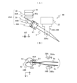
- FIG. 1A is a perspective view showing the robot apparatus of the first embodiment, and FIG. 1B is an enlarged perspective view showing an example of tweezers to be held;
- FIG. 2(A) is a front view showing the robot hand of the first embodiment,
- (B) is a view showing a control section of the robot hand,
- (C) is a side view of the main part of FIG. 2(A), and
- (D) is a cross-sectional view showing a second connecting part 40 of FIG.
- A) is a sectional view showing the damping mechanism in FIG. 2 (A),
- (B) is a front view of FIG. 3 (A), and
- (C) is a front view showing a modified damping mechanism.
- (A) is a front view showing the rotating mechanism in FIG.
- FIG. 2(A), and (B) and (C) are cross-sectional views taken along line AA in FIG. 4(A).
- (A) is a front view showing a main part of a robot hand of a modification
- (B) is a bottom view showing a rotation mechanism of this modification.
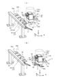
- FIG. 2 is a perspective view showing a state in which the robot hand of the first embodiment is joined to the tip of a robot arm;
- (A) is a diagram showing an example of a tool used to hold tweezers in the tweezers holding portion,
- (B) is a diagram showing a modification of the tweezers holding portion, and
- (C) is a diagram showing another modification of the tweezers holding portion.
- FIG. 1 is an explanatory diagram of the operation of receiving the tweezers holder from the tweezers stand, and (B) is an explanatory diagram of the operation after receiving the tweezers holder.
- FIG. 4 is a flow chart showing an example of a method of using and controlling a robot hand; 8A is a flowchart showing an example of a control method for a robot device, and B is a flowchart showing operations of main parts of a modification;
- 12A is a front view showing a robot hand of a second embodiment, and FIG. 12B is a diagram showing a simplified damping mechanism in FIG. 12A;
- FIG. 11 is a perspective view showing a state in which the robot hand of the second embodiment is joined to the tip of the robot arm;
- FIG. 4 is a perspective view showing various examples of tweezers;
- FIG. 4 is a perspective view showing various examples of tools similar to tweezers (tweezers type tools). It is a figure which shows the modification which hold
- A is a perspective view showing an example of a horizontal articulated robot
- (B) is a perspective view showing an example of a parallel link robot
- (C) is a perspective view showing an example of an orthogonal robot.
- FIG. 1A shows a vertically articulated robot device 2 of this embodiment.
- the X-axis and the Y-axis which are parallel and perpendicular to the installation surface of the robot device 2 are taken, and the Z-axis is taken perpendicular to the installation surface.
- the installation surface is substantially horizontal, and the upper side of the installation surface (opposite direction to the vertical direction) is the + direction of the Z axis.
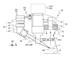
- the robot apparatus 2 includes a robot main body 4, a robot hand 6 joined to the robot main body 4, a control device 10 that controls the operation of the robot main body 4, and a control device 12 that controls the operation of the robot hand 6.
- the robot main body 4 includes a base portion 14, and a first robot arm 18A, a second robot arm 18B, and a third robot arm 18C which are connected to the base portion 14 in order so as to be displaceable.
- a robot hand 6 is joined to the distal end portion 20A of the third robot arm 18C.
- the robot hand 6 can also be called an end effector.
- the first robot arm 18A can control the rotation angle ⁇ 1 and the turning angle ⁇ 1
- the second robot arm 18B can control the rotation angle ⁇ 2 and the turning angle ⁇ 2
- the third robot arm 18C can control the rotation angle ⁇ 3 and the turning angle ⁇ 3.
- the third robot arm 18C has a rotating portion 20B that changes the rotation angle ⁇ 3 of the distal end portion 20A and an inclination driving portion 20C that changes the turning angle ⁇ 3.
- the rotating portion 20B and the tilt driving portion 20C each have a driving motor and an encoder for detecting the rotation angle.
- the other robot arms 18A, 18B have similar drives. Therefore, the robot hand 6 joined to the third robot arm 18C can control the position (including the angle) with six degrees of freedom including the positions in the X, Y and Z directions and rotation angles around three axes.
- the robot device 2 also includes an imaging device 22 and an illumination device 24 .
- the imaging device 22 and the lighting device 24 are attached to the robot hand 6, but the imaging device 22 and the lighting device 24 may be provided at positions other than the robot hand 6, such as the distal end 20A of the robot arm 18C, the measurement position on the installation surface of the robot device 2, or the wall or ceiling of the room where the robot device 2 is installed.
- the robot hand 6 of this embodiment holds tweezers 8 .
- the tweezers 8 may be any tweezers such as commercially available, custom made, home made, or modified from commercially available products. That is, the tweezers 8, as shown enlarged in FIG.
- 1(B) has a pair of flexible elongated flat plate-like movable parts (contact parts or opening/closing parts) 8b and 8c that are manufactured to be openable and closable with respect to the fulcrum 8a.
- movable parts 8b and 8c By pushing inwardly force points 8bF and 8cF substantially intermediate between the fulcrum 8a of the tweezers 8 and the points of action 8d and 8e at the tips of the movable parts 8b and 8c, the movable parts 8b and 8c are closed and the object OB can be gripped or supported between the points of action 8d and 8e.
- the movable portions 8b and 8c can be opened to release the object OB.
- the robot hand 6 holds the fulcrum 8 a of the tweezers 8 .
- the tweezers 8 may be fixed at one movable portion 8b and movable only at the other movable portion 8c. That is, the movable parts 8b and 8c need only be relatively openable and closable. Also, instead of the tweezers 8, tweezers having three or more contact portions (movable portions) can be used. At this time, only at least one contact portion among the three or more contact portions may be movable, and the other contact portions may be fixed.
- FIG. 2(A) shows the robot hand 6 in FIG. 1(A), and FIG.
- 2(A) shows a state in which the robot hand 6 is joined to the lower end of the tip portion 20A of the robot arm 18C parallel to the Z-axis so that the opening/closing direction of the movable portion of the tweezers 8 held is parallel to the Y-axis (Y-direction).
- the robot hand 6 includes a hand main body 28 joined to the lower end of the tip 20A, a tweezers holding part 26 connected to the hand main body 28 and holding the tweezers 8, and a pair of fingers 38A and 38B for opening and closing the movable part of the tweezers 8 held by the tweezers holding part 26.
- the hand main body 28 also has a flat joint 30 joined to the tip 20A, an operating section 32 that is fixed to the joint 30 and moves the fingers 38A and 38B in the Y direction, and a disk-shaped first connecting section 36 that is fixed to the -X direction side surface of the operating section 32 via a damping mechanism 34 (details will be described later).
- the joint portion 30 is mechanically (fixed by a screw, fixed by a movable claw mechanism, fixed by a permanent magnet, etc.) or electrically (fixed by an electromagnet, etc.) to the distal end portion 20A. Further, the joint 30 is provided with a connecting portion such as an electric wiring, a compressed air pipe, and/or a vacuum suction pipe as required.
- the joining portion 30 is provided with positioning portions (not shown) such as a plurality of protrusions or recesses so that the position and the rotation angle with respect to the tip portion 20A have predetermined values.
- the tweezers holding part 26 includes a disk-shaped second connecting part 40 that is detachably connected to the first connecting part 36 of the hand main body 28, a rotating part 42 that is rotatable within a predetermined range (for example, several degrees) around an axis parallel to the Z-axis with respect to the second connecting part 40, a fixed part 44 that is fixed to the bottom surface of the rotating part 42, and a holding part 46 that holds and fixes the fulcrum 8a of the tweezers 8 on one surface of the fixed part 44. and As an example, by covering the fulcrum 8a of the tweezers 8 arranged on one surface of the fixed portion 44 with the holding portion 46 (see FIG.
- the fulcrum 8a of the tweezers 8 can be fixed to the fixed portion 44 and the tweezers 8 can be stably held.
- the tips (action points 8d and 8e) of the movable portions 8b and 8c of the tweezers 8 protrude in the +X direction of the fingers 38A and 38B through between the fingers 38A and 38B.
- a method for holding the tweezers 8 a method of placing the fulcrum 8a of the tweezers 8 on the fixing portion 44 and holding down with a leaf spring or the like from above, or a method of fixing the fulcrum of the tweezers 8 or other parts using a gripping tool such as a double clip can be used.
- first connecting portion 36 and the second connecting portion 40 are detachably connected by permanent magnets provided in the first connecting portion 36 and the second connecting portion 40, for example.
- a plurality of convex portions 36a are provided on the bottom surface of the first connecting portion 36
- corresponding concave portions 40b are provided on the upper surface of the second connecting portion 40 (see FIG. 4A).
- a method for detachably connecting the second connecting portion 40 to the first connecting portion 36 a method of mechanically connecting with a movable pawl mechanism or the like, a method of connecting with an electromagnet, a method of connecting by vacuum suction, or the like can be used.
- a U-shaped groove portion 40a (see FIG. 2(D)) is provided in the second connecting portion 40 of the tweezers holding portion 26. As shown in FIG. By aligning the groove portion 40a with a base 64a (see FIG. 8A) of the tweezers stand 64, which will be described later, and installing the second connecting portion 40 in the concave portion 64b of the tweezers stand 64, the tweezers holding portion 26 can be installed (stored) in the tweezers stand 64 with the rotation angle adjusted.
- a plurality of tweezers holding portions 26 in which tweezers having different shapes are fixed between the fixing portion 44 and the pressing portion 46 may be prepared in advance and installed on the tweezers stand 64 . Then, only by moving the robot hand 6 to separate and connect the first connecting part 36 and the second connecting part 40, the tweezers (tweezers holding part 26) held by the robot hand 6 can be easily replaced with tweezers corresponding to the object.
- the tweezers holding portion 26 holding the tweezers 8 is also referred to as a tweezers unit 27 .
- FIG. 2(C) is a side view of FIG. 2(A).
- the operating portion 32 has a rotary motor portion 32a and a conversion portion 32b that reduces the amount of rotation of the rotary motor portion 32a and converts it into linear motion.
- the rotary motor section 32a is composed of an encoder for detecting a rotation angle (amount of movement of the fingers 38A and 38B), a stepping motor, a DC motor, or the like.
- the actuating portion 32 causes the pair of fingers 38A, 38B to move so as to decrease or increase the Y-direction spacing in order to open or close the spacing of the movable portions 8b, 8c of the tweezers 8 in the opening/closing direction (here, the Y-direction).
- hemispherical protrusions 38Aa and 38Ba are provided inside the fingers 38A and 38B, and the protrusions 38Aa and 38Ba come into contact with the points of force of the movable portions 8b and 8c of the tweezers 8 (or the points between the fulcrum 8a and the points of action 8d and 8e) and push the movable portions 8b and 8c in the +Y direction and the ⁇ Y direction. closed), the object OB can be gripped, pinched, or supported between action points 8d and 8e at the tips of the movable parts 8b and 8c.
- the distance between the movable portions 8b and 8c is increased (the movable portions 8b and 8c are opened), and the tweezers 8 can be separated from the object OB.
- the fingers 38A and 38B may be operated to move independently of each other in the Y direction.
- the -Y direction finger 38A is on standby at the outermost (-Y direction) position (hereinafter also referred to as the standby position) within the Y direction movable range
- the +Y direction finger 38B is on standby at the outermost (+Y direction) position (hereinafter also referred to as the standby position) within the Y direction movable range.
- the projections 38Aa and 38Ba of the fingers 38A and 38B are made of, for example, a material with low frictional resistance (such as Teflon (registered trademark)). Therefore, the tweezers 8 held by the tweezers holding portion 26 can slightly move (slide) in the Z and X directions with respect to the fingers 38A and 38B.
- the shape of the protrusions 38Aa and 38Ba may be a semi-elliptical shape that is long in the Z direction, or a semicylindrical shape that is long in the Z direction.
- the material of the protrusions 38Aa and 38Ba is not necessarily limited to a material with low frictional resistance.
- FIG. 2(B) shows the control device 12 of the robot hand 6 .
- the control device 12 includes a hand control unit 48A that transmits and receives control information (GI, MC) to and from the control device 10 of FIG. 1A and controls the operation of the entire device, a finger control unit 48B that controls the movement of the fingers 38A and 38B via the operation unit 32, and reaction forces (forces by the fingers 38A and 38B) from the movable portions 8b and 8c of the tweezers 8 against the fingers 38A and 38B as a finger gripping force FF. It has a finger gripping force detection unit 48C for detecting, and a storage unit 48D for storing various data.
- GI control information
- MC control information
- the control information GI input to the control device 12 includes, for example, an instruction to start gripping the object by the tweezers 8 and an instruction to release the gripping of the object
- the control information MC output from the control device 12 to the control device 10 includes, for example, information indicating completion of gripping the object by the tweezers 8 and information indicating completion of releasing the grip of the object by the tweezers 8 (completion of detachment of the tweezers from the object).
- the storage unit 48D may include, for example, a storage device such as a HDD (Hard Disk Drive) or an SSD (Solid State Drive), or a non-volatile memory such as a USB (Universal Serial Bus memory).
- the storage unit 48D stores programs of the control device 12, various setting values, and the like.
- the finger gripping force detection unit 48C detects the finger gripping force FF from the current flowing through the rotary motor unit 32a of the operating unit 32, and the finger control unit 48B controls the operations of the fingers 38A and 38B so that the detected finger gripping force FF is equal to or lower than a preset level (standard value). This can prevent damage to the tweezers 8, the fingers 38A and 38B, and/or the object.
- strain gauges provided on the fingers 38A and 38B, or sensors capable of detecting the finger gripping force FF, such as pressure sensors, can be used.
- the damping mechanism 34 in FIG. 2(A) includes a support member 50 having two flat plate portions 50a and 50b that are fixed to the -X direction side of the operating portion 32 and face each other, a bridge member 51 that extends from between the support members 50 to the first connecting portion 36, and two cylindrical slide shafts 52A that are provided between the flat plate portions 50a and 50b so as to pass through the bridge member 51.
- 52B and linear bearings 53A, 53B fixed to the bridge member 51 so as to accommodate the slide shafts 52A, 52B.
- the linear bearings 53A and 53B allow the bridge member 51 to smoothly move (displace) between the two flat plate portions 50a and 50b of the support member 50 in the Z direction.
- the tweezers holding portion 26 Since the first connecting portion 36 is fixed to the bridge member 51, and the tweezers holding portion 26 is connected to the first connecting portion 36 via the second connecting portion 40, the tweezers holding portion 26 also moves in the Z direction in conjunction with the bridge member 51 and the first connecting portion 36.
- compression coil springs 54A and 54B are installed between the linear bearings 53A and 53B and the upper flat plate portion 50b, and stoppers STA and STB of predetermined lengths are provided on the upper surface of the lower flat plate portion 50a and the lower surface of the upper flat plate portion 50b, respectively. Therefore, normally, the bridge member 51 is biased downward (-Z direction) toward the stopper STA by the biasing force of the coil springs 54A and 54B and the weight of the bridge member 51, the tweezers holding portion 26, and the like. On the other hand, when a force in the +Z direction is applied to the bridge member 51, the bridge member 51 can move upward toward the stopper STB. The distance between the stoppers STA and STB defines the amount of movement of the bridge member 51 (and thus the tweezers holding portion 26) in the Z direction. Note that other elastic members may be used instead of the coil springs 54A and 54B.
- the damping mechanism 34 of this embodiment holds the tweezers holding portion 26 with respect to the operating portion 32 of the hand body portion 28 .
- the bridge member 51 (tweezers holding portion 26) of the damping mechanism 34 moves in the +Z direction with respect to the support member 50 in order to release the force. Therefore, it is possible to prevent deformation of the object and the tip of the tweezers 8 due to the force applied to the object and the stage.
- the protrusions 38Aa and 38Ba of the fingers 38A and 38B are made of a material that easily slides on the tweezers 8, when the tweezers holding section 26 moves in the Z direction, the tweezers 8 can move smoothly in the Z direction with respect to the protrusions 38Aa and 38Ba of the fingers 38A and 38B.
- the robot hand 6A has a damping mechanism 34A that connects the hand main body 28 and the first connecting portion 36.
- the damping mechanism 34A includes a flat support member 50A fixed to the ⁇ X direction side surface of the operating portion 32, a plurality of (two as an example) leaf springs 55 separated in the Z direction connecting the support member 50A and the first connecting portion 36, and a ⁇ Z direction side stopper STC and a +Z direction side stopper STD provided on the support member 50A.
- Other configurations are the same as those in FIG. It should be noted that other elastic members may be used instead of the leaf springs 55 .
- the tweezers holding portion 26 is held by the actuating portion 32 of the hand body portion 28 by the damping mechanism 34A.
- the elastic deformation of the leaf spring 55 causes the first connecting portion 36 (tweezers holding portion 26) to move in the +Z direction with respect to the support member 50A in order to release the force. Therefore, it is possible to prevent deformation of the object and the tip of the tweezers 8 due to the force applied to the object and the stage. Furthermore, it is possible to prevent damage to the fingers 38A and 38B (tweezers holding portion 26), the tweezers 8, and the object due to force applied to the object and the stage.
- FIG. 4(A) shows a part of the tweezers holding portion 26 and the operating portion 32 of FIG. 2(A), and FIGS. 4(B) and (C) are cross-sectional views along line AA of FIG. 4(A).
- FIG. 4A shows a state in which the groove portion 40a of the second connecting portion 40 is inserted into the base 64a of the tweezers stand 64 (see FIG. 8A), and the first connecting portion 36 is separated from the second connecting portion 40.
- the second connecting portion 40 is connected to the first connecting portion 36 .
- a rotary bearing 56 provided on the rotating portion 42 is fitted to a linear guide 40c parallel to the Z-axis on the bottom surface of the second connecting portion 40 of the tweezers holding portion 26.
- the rotating portion 42 can smoothly rotate about an axis parallel to the Z-axis with respect to the second connecting portion 40 .
- a convex portion 57 is provided on the upper surface of the rotating portion 42
- stoppers STE and STF are provided on the bottom surface of the second connecting portion 40 so as to sandwich the convex portion 57 .
- the stoppers STE and STF limit the rotatable angular range of the rotating portion 42 to a predetermined angular range (for example, several degrees). In this case, the rotation of the rotating part 42 about an axis parallel to the Z axis can be called yawing in the Y direction.
- the fulcrum of the tweezers 8 is held by the fixed part 44 and the pressing part 46 on the bottom surface of the rotating part 42 .
- the mounting error of the tweezers 8 with respect to the fixed portion 44, the symmetry of the fingers 38A and 38B actuated by the actuating portion 32, and a small amount of rotation as shown in FIG.
- the center line SL1 of the tweezers 8 is inclined by an angle ⁇ 1 with respect to the center line SL2 of the fingers 38A and 38B, and the center of the tweezers 8 is shifted in the -Y direction from the centers of the fingers 38A and 38B.
- the rotating portion 42 is rotatable with respect to the second connecting portion 40 .
- the finger 38A and 38B are moved in the +Y direction and the -Y direction from the state of FIG. 4B to narrow the Y-direction spacing between the fingers 38A and 38B
- the finger 38A first comes into contact with the -Y direction movable portion 8b of the tweezers 8, the rotating portion 42 (tweezers 8) rotates counterclockwise, and the tip portion of the tweezers 8 moves in the +Y direction.
- the center line SL1 of the tweezers 8 is aligned with the center line SL2 of the fingers 38A and 38B as shown in FIG.
- the position of the tip of the tweezers 8 in the Y direction matches the designed value based on the positions of the fingers 38A and 38B.
- the tweezers holding part 26 (robot hand 6) is moved in the +X direction so that the tip of the tweezers 8 is inserted in the direction of the object OB, and the distance between the fingers 38A and 38B is narrowed.
- the positions of the fingers 38A and 38B in the Y direction are accurately measured by the encoders in the operation unit 32, so the positions of the tips of the tweezers 8 in the Y direction have reproducibility.
- FIG. 5(A) shows a main part of a modified robot hand 6B
- FIG. 5(B) is a bottom view of FIG. 5(A).
- the rotating part 42 is omitted from the tweezers holding part 26A, and the second connecting part 40 is connected to the first connecting part 36 of the hand main body.
- a fixing portion 44A for holding the tweezers 8 is connected to a fulcrum portion 44B on the bottom surface of the second connecting portion 40 via a plate spring 59.
- the fulcrum of the tweezers 8 is held between the fixing portion 44A and the pressing portion 46A.
- the plate spring 59 allows the fixing portion 44A that holds the tweezers 8 to rotate (yawing) about an axis parallel to the Z axis with respect to the fulcrum portion 44B of the second connecting portion 40 within a predetermined range (for example, several degrees).
- Two stoppers (not shown) that define the rotation angle of the tweezers 8 are also provided on the bottom surface of the second connecting portion 40 .
- the finger 38B when the fingers 38A and 38B are moved in the +Y direction and the -Y direction to narrow the distance between the fingers 38A and 38B in the Y direction, for example, the finger 38B first comes into contact with the +Y direction movable part 8c of the tweezers 8, the fixed part 44A (tweezers 8) rotates counterclockwise, and the tip of the tweezers 8 moves in the -Y direction. Furthermore, by narrowing the distance between the fingers 38A and 38B, the centerline of the tweezers 8 is aligned with the centerline of the fingers 38A and 38B, and the positioning of the tweezers 8 in the Y direction is completed. In this state, by narrowing the distance between the fingers 38A and 38B, the movable portions 8b and 8c of the tweezers 8 can accurately pinch the object.
- FIG. 6 shows a state in which the robot hand 6 of this embodiment is joined to the distal end portion 20A of the robot arm 18C.
- the tweezers holding portion 26 is connected to the operating portion 32 via the damping mechanism 34 , and the tweezers 8 are held by the tweezers holding portion 26 .
- the imaging device 22 is attached to the surface of the operating portion 32 opposite to the tweezers holding portion 26 via the attachment member 60 , and the illumination device 24 is attached to the front surface of the imaging device 22 .
- the imaging device 22 has, for example, a CMOS-type or CCD-type imaging device and a lens.
- the focal plane of the imaging device 22 may be set to include a wide area below the tip of the tweezers 8 to search for the object OB in a wide field of view. Then, when the object OB is found, the field of view 22F of the imaging device 22 may be set so as to include an area surrounding the tip of the tweezers 8 held by the tweezers holding portion 26 and the supported object OB.
- the imaging signal of the imaging device 22 is subjected to image processing to determine the relative positional relationship between the tip of the tweezers 8 and the object OB, thereby positioning the tweezers 8 with respect to the object OB with high accuracy.
- FIG. 7A an example of a method of holding the tweezers 8 in the tweezers holding portion 26 of the present embodiment or exchanging the tweezers 8 held by the tweezers holding portion 26 will be described.
- a replacement tool 62 having U-shaped side surfaces and a mount 62a inserted into the groove 40a of the second connecting portion 40 of the tweezers holding portion 26 is used.
- the second connecting portion 40 of the tweezers holding portion 26 is hung on the base 62a of the exchange tool 62 via the groove portion 40a.
- the fulcrum of the tweezers 8 to be held is placed on the fixed portion 44, the fulcrum portion is covered with the holding portion 46, and the holding portion 46 is temporarily fixed to the fixed portion 44 with the bolt B1. In this state, the tweezers 8 can be moved within a predetermined narrow range.
- the positional relationship between the base 62a and the corner 62b of the exchange tool 62 is set so as to be the designed positional relationship between the second connecting portion 40 and the distal end portion of the tweezers 8 held by the tweezers holding portion 26. Therefore, by fixing the pressing portion 46 to the fixing portion 44 with the bolt B1 in a state where the tips of the tweezers 8 (points of action 8d and 8e) are pressed against the corner portion 62b of the replacement tool 62, the tweezers 8 can be held in the designed positional relationship with respect to the tweezers holding portion 26.
- the tweezers holding portion 26 is made to hold another tweezers 8 using the replacement tool 62.
- the tweezers 8 on the market include long tweezers and short tweezers in addition to the standard length tweezers.
- a long hole may be provided in the holding portion 46 so that the holding portion 46 can slide in the longitudinal direction of the tweezers along the fixing portion 44 as necessary.
- FIG. 7B shows an example of the tweezers holding portion 26 capable of holding, for example, three types of tweezers 8S, 8, and 8L having different lengths.
- FIG. 7B shows an example of the tweezers holding portion 26 capable of holding, for example, three types of tweezers 8S, 8, and 8L having different lengths.
- a fixed portion 44C having a long mounting surface along the longitudinal direction of the tweezers to be held is attached to the lower surface of the rotating portion 42 of the tweezers holding portion 26 .
- the mounting surface of the fixing portion 44C is provided with four threaded holes 44Ca for short tweezers, four threaded holes 44Cb for normal length tweezers, and four threaded holes 44Cc for long tweezers.
- the pressing portion 46B is formed with two rows of holes through which a total of eight bolts B1 are passed along the longitudinal direction of the tweezers.
- each of the screw holes 44Ca to 44Cc may be eight screw holes.
- the holding part 46B is opposed to the lower screw hole 46Ca of the fixing part 44C, the fulcrum of the tweezers 8S is sandwiched between the fixing part 44C and the holding part 46B, and the holding part 46B is fixed to the fixing part 44C with bolts B1 at appropriate four positions out of the eight positions, for example.
- the pressing portion 46B is opposed to the screw hole 44Cb in the middle of the fixing portion 44C, and the fulcrum of the tweezers 8 is sandwiched between the fixing portion 44C and the pressing portion 46B, and the pressing portion 46B is fixed.
- the pressing portion 46B is opposed to the upper screw hole 44Cc of the fixing portion 44C, and the fixing portion 44C and the pressing portion 46B sandwich the fulcrum of the tweezers 8L, and the pressing portion 46B is fixed.
- the fixing portion 44C of FIG. 7B it is possible to hold a plurality of types of tweezers having different lengths using the same fixing portion 44C.
- FIG. 7(C) shows another example of the tweezers holding portion 26 capable of holding the three types of tweezers 8S, 8, 8L described above.
- a fixed portion 44C1 having a narrow width is attached to the lower surface of the rotating portion 42 of the tweezers holding portion 26.
- the mounting surface of the fixing portion 44C1 is provided with two threaded holes 44C1a for short tweezers, two threaded holes 44C1b for normal length tweezers, and two threaded holes 44C1c for long tweezers.
- the fulcrums of the tweezers 8S, 8, 8L are held by four bolts B2 between the two pressing portions 46B1, 46B2, respectively, and the upper portion of one of the wide pressing portions 46B1 is attached to the fixing portion 44C1 by bolts B1.
- two openings for screw holes are formed in a portion of the holding portion 46B1 facing the fixing portion 44C1.
- the upper portion of the pressing portion 46B1 holding the tweezers 8S is opposed to the lower screw hole 46C1a of the fixing portion 44C1, and the pressing portion 46B1 is fixed to the fixing portion 44C1 with two bolts B1.
- the upper portion of the pressing portion 46B1 holding the tweezers 8 is opposed to the intermediate screw hole 44C1b of the fixing portion 44C1, and the pressing portion 46B1 is fixed to the fixing portion 44C1 with two bolts B1.
- the upper portion of the pressing portion 46B1 holding the tweezers 8L is opposed to the upper screw hole 44C1c of the fixing portion 44C1, and the pressing portion 46B1 is fixed to the fixing portion 44C1 with two bolts B1.
- the bolt B2 is loosened and the tips of the tweezers 8S, 8, 8L are pressed against the corner 62b of the replacement tool 62 shown in FIG.
- the movable portions of the tweezers 8S, 8, 8L do not contact the fixed portion 44C1, so that the movable portions of the tweezers 8S, 8, 8L can be moved more smoothly to grip or support the object.
- the robot device 2 of this embodiment includes a tweezers stand 64 shown in FIGS. 8(A) and (B).
- the tweezers stand 64 has a base 64a provided with a plurality of recesses 64b.
- the tweezers holding portion 26 separated from the hand main body portion 28 (first connecting portion 36) of the robot hand 6 can be installed in each of the plurality of concave portions 64b such as positions P1 and P2.
- tweezers holding portions 26 tweezers units 27
- the robot arm 18C is driven to connect the first connecting portion 36 of the robot hand 6 joined to the distal end portion 20A of this arm onto the second connecting portion 40 of the tweezers holding portion 26 at the position P1.
- an imaging device 22 and a lighting device 24 are attached to the operating portion 32 of the robot hand 6 . Therefore, just before connecting the second connecting portion 40 to the first connecting portion 36, the imaging signal of the imaging device 22 may be processed to align the first connecting portion 36 and the second connecting portion 40 in the X direction and the Y direction so that the tip of the tweezers 8 held by the tweezers holding portion 26 is at a predetermined position within the field of view 22F of the imaging device 22.
- the tweezers holder 26 mounted on the pedestal 64a does not move in the Z direction. Then, by moving the robot arm 18C in the +X direction, the tweezers holder 26 can be transferred from the tweezers stand 64 to the robot hand 6, as shown in FIG. 8B.
- the robot arm 18C is driven to return the tweezers holding portion 26 to the position P1, and then the robot arm 18C is raised in the +Z direction to separate the second connecting portion 40 (tweezers holding portion 26) from the first connecting portion 36.
- the tweezers holding portion 26 (second connecting portion 40) at the position P2 may be connected to the first connecting portion 36 of the hand main body 28 by the method described above to transfer the tweezers holding portion 26 to the robot hand 6.
- the tweezers holding portion 26 of the robot hand 6 can be easily replaced with one of the plurality of tweezers holding portions 26 holding tweezers of various shapes.
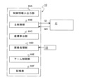
- FIG. 9 shows the control device 10 of the robot device 2 of FIG. 1(A).
- the control device 10 includes, for example, a control information input/output unit 66A that inputs and outputs control information (such as the type of tweezers to be used and the position of an object to be processed) with an operator, a main control unit 66B that transmits and receives control information GI and MC to and from the control device 12 of the robot hand 6 and controls the operation of the entire device, and a robot hand at the tip of the third robot arm 18C that processes the detection results of at least six-axis encoders that detect the movements of the robot arms 18A to 18C. 6 and a coordinate calculator 66C for calculating the coordinates of the tip of the tweezers 8 held by 6 and the rotation angle.
- control information input/output unit 66A that inputs and outputs control information (such as the type of tweezers to be used and the position of an object to be processed) with an operator
- control device 10 has an image processing section 66D that processes the imaging signal of the imaging device 22 and obtains the positional relationship between, for example, the tip of the tweezers 8 held by the robot hand 6 and the object, an arm control section 66E that controls the movements of the robot arms 18A to 18C based on the processing results of the coordinate calculation section 66C and the image processing section 66D, and a storage section 66F that stores various data.
- the storage unit 66F has a configuration similar to that of the storage unit 48D in FIG. 2B, and the storage unit 66F stores programs for the control device 10, various setting values, and the like.
- the fulcrum of the tweezers 8 is fixed to the fixing portion 44 (and the pressing portion 46) of the tweezers holding portion 26 in FIG. 2A using, for example, the replacement tool 62 in FIG.
- a plurality of tweezers holding portions 26 (tweezers units 27) holding tweezers 8 having different shapes fixed in this way are installed on the frame 64a of the tweezers stand 64 in FIG. 8A (step 104).
- the hand body portion 28 of the robot hand 6 is joined to the distal end portion 20A of the robot arm 18C via the joint portion 30 .
- step 106 the tip portion 20A (robot hand 6) of the robot arm 18C is moved above, for example, the position P1 of the tweezers stand 64, the tip portion 20A is lowered to connect the first connecting portion 36 of the hand body portion 28 to the second connecting portion 40 of the tweezers holding portion 26, and the robot arm 18C is moved in the +X direction.
- the tweezers holder 26 is transferred from the tweezers stand 64 to the robot hand 6 .
- step 110 the finger control section 48B starts operating or driving (moving in the Y direction) the fingers 38A and 38B, and the finger gripping force detecting section 48C starts detecting the finger gripping force FF.
- the fingers 38A, 38B come into contact with the movable parts 8b, 8c of the tweezers 8 (the contact of the fingers 38A, 38B can be detected from the slight stepwise change in the detected value of the finger gripping force FF).
- the center line of the fingers 38A, 38B and the center line of the tweezers 8 are inclined, for example, one finger 38A contacts one movable portion 8b of the tweezers 8 and the tweezers 8 rotates, thereby aligning the tweezers 8 in the rotational direction.
- the gripping force of fingers 38A and 38B is further increased (step 112).
- the movable parts 8b and 8c of the tweezers 8 begin to close.
- the hand control unit 48A determines whether the detected value of the finger gripping force FF has reached a set level (a level at which the tweezers 8 can stably grip or support the object OB).
- a set level a level at which the tweezers 8 can stably grip or support the object OB.
- the hand control unit 48A maintains the gripping force of the fingers 38A and 38B via the finger control unit 48B, and outputs gripping completion information (control information MC) to the controller 10 of the robot device 2 (step 116).
- the rotation of the rotary motor portion 32a may be stopped to keep the fingers 38A and 38B stationary.
- the robot arms 18A to 18C of the robot device 2 are driven to move the tweezers holder 26 of the robot hand 6 and the object to the target position.
- the hand control unit 48A determines whether or not a grip release command (control information GI) for releasing the grip of the object by the tweezers 8 has been input from the control device 10.
- a grip release command control information GI
- the process proceeds to step 120, and the finger control section 48B starts moving the fingers 38A and 38B in the Y direction to reduce the gripping force.
- the movable parts 8b, 8c of the tweezers 8 are completely opened, allowing the tweezers 8 to be separated from the object.
- the hand control unit 48A outputs gripping release completion information (control information MC) indicating that the gripping of the target object by the tweezers 8 has been completed to the control device 10 (step 124). This completes the gripping and releasing of the gripping of the object by the tweezers 8 held by the tweezers holding portion 26 .
- the robot hand 6 can easily hold or replace the tweezers 8 of various shapes. Furthermore, since the detected value of the finger gripping force FF is set to the set level, damage to the fingers 38A, 38B, the tweezers 8, and the object can be prevented when the object is gripped by the tweezers 8.
- step 132 in FIG. 11A the hand body portion 28 of the robot hand 6 is joined to the tip portion 20A of the robot arm 18C. Thereafter, for example, the operator inputs the type of tweezers to be used into the control device 10 (step 134), and inputs the original positions and destination positions of a plurality of objects to be gripped by the tweezers (step 136).
- the robot arms 18A to 18C are driven under the control of the main control unit 66B, and the tweezers holding unit 26 to be used is connected to the hand main unit 28 joined to the robot arm 18C in the tweezers stand 64 of FIG. 8(A) (step 138).
- the robot arms 18A to 18C are driven to move the tweezers 8 held by the robot hand 6 at the tip of the robot arm 18C to the original position of the object (step 140), and the fingers 38A and 38B of the robot hand 6 are operated to grip the object with the tweezers 8 (step 142).
- the tweezers 8 held by the robot hand 6 move to the position where the object is transferred (step 144), and the fingers 38A and 38B of the robot hand 6 are actuated to remove the object from the tweezers 8 (step 146).
- the main control section 66B determines whether or not any objects to be transported remain (step 148), and if any objects remain, the operations of steps 140 to 146 are repeated. If there are no objects to be transported remaining, the operation ends.
- the robot hand 6 holds the tweezers 8 having a shape corresponding to the object, and the tweezers 8 can be used to move the object from the original position to the destination position.
- the position of the tweezers 8 held by the robot hand 6 may be a position calculated by the coordinate calculator 66C from values of a plurality of encoders of the robot arms 18A to 18C.
- the operations of steps 140 to 144 of FIG. 11B may be used instead of the operations of steps 140 to 144 of FIG. 11A.
- the tweezers 8 held by the robot hand 6 are moved to the original position of the object.
- the image capturing device 22 captures an image of a range including the tips of the tweezers 8 and the object.
- the image processing section 66D of the control device 10 processes the imaging signal of the imaging device 22 and calculates the amount of positional deviation between the tips of the tweezers 8 and the object.
- the robot arm 18C is driven so as to correct the positional deviation amount.
- the fingers 38A and 38B are driven by the robot hand 6 to grip the object with the tweezers 8 (step 142).
- the tweezers 8 held by the robot hand 6 are moved to the destination of the object (step 144).
- the position of the tweezers 8 calculated from the detection results of a plurality of encoders is corrected by the amount of positional deviation obtained from the image captured by the imaging device 22, so that the tweezers 8 can grip a more appropriate portion of the object.
- the robot hand 6 of the present embodiment is a robot hand device that can be joined to the robot arm 18C. Fingers 38A and 38B that are operated (including driven or moved) by the hand main body 28 so as to open and close the plurality of movable parts of the tweezers 8 that are held in place.
- the robot device 2 of the present embodiment includes a robot hand 6, a robot arm 18C to which the hand body portion 28 of the robot hand 6 is joined, and a driving portion (robot arms 18A and 18B, a rotating portion 20B, and an inclination driving portion 20C) for driving the robot arm 18C.
- a robot hand 6 a robot arm 18C to which the hand body portion 28 of the robot hand 6 is joined
- a driving portion robot arms 18A and 18B, a rotating portion 20B, and an inclination driving portion 20C
- tweezers having a shape corresponding to the object can be used, and the tweezers can be opened and closed, so that objects of various shapes or states can be grasped (or supported), transported, and processed (or manipulated) can be performed efficiently.
- the tweezers held by the robot hand 6 can be efficiently and easily replaced with other tweezers. Therefore, various operations can be performed efficiently. Furthermore, since commercially available tweezers 8 can be used, for example, there is no need to separately develop a gripping device for an object, and the manufacturing costs of the robot hand 6 and the robot device 2 can be suppressed.
- control method of the robot hand 6 of the present embodiment includes a step 102 of holding the tweezers 8 with the tweezers holding portion 26 of the robot hand 6, a step 106 of detachably connecting the tweezers holding portion 26 to the hand body portion 28 of the robot hand 6, a step 110 of positioning the movable portions 8b and 8c of the tweezers 8 held by the tweezers holding portion 26 by operating the fingers 38A and 38B of the robot hand 6, and the movable portion 8 of the tweezers 8.
- b, 8c are closed by fingers 38A, 38B to support the object by movable parts 8b, 8c.
- control method of the robot device 2 of this embodiment includes step 132 of joining the hand main body 28 of the robot hand 6 to the robot arm 18C, step 138 of connecting the tweezers holding part 26 holding the tweezers 8 to the hand main body 28 joined to the robot arm 18C, step 140 of moving the robot hand 6 via the robot arm 18C to a position where the tweezers 8 held by the tweezers holding part 26 can support an object, and a robot.
- the robot hand 6 can hold the tweezers 8 having a shape corresponding to the object by simply connecting the tweezers holding portion 26 holding the tweezers 8 to the hand body portion 28 .
- the tweezers 8 being held can be efficiently positioned and opened/closed.
- the tweezers 8 having a shape corresponding to the object can be used to move the object efficiently or without damaging the object.
- the object gripped by the tweezers 8 held by the tweezers holding portion 26 is moved.
- the robot hand 6 of the above-described embodiment is movable with six degrees of freedom, it is possible to perform various operations such as pressing, twisting, pulling out, peeling, or pasting an object gripped or supported by the tweezers 8 held by the robot hand 6.
- the configuration of the robot device 2 is not limited to the above-described embodiment.
- the two fingers 38A and 38B are movable.
- the fixed portion 44 may be lengthened so that only one movable portion 8b of the tweezers 8 is movable by one finger 38A, and the other movable portion 8c of the tweezers 8 is placed on the fixed portion 44 to fix the movable portion 8c.
- the other finger 38B may be omitted.
- the other movable portion 8c of the tweezers 8 becomes a fixed portion.
- the other finger 38B may be fixed and arranged so as to support the fixed movable portion 8c.
- tweezers 8 in addition to those that support the object with a plurality of movable parts (contact parts) that are all movable, those that support the object with at least one movable part (contact part) and at least one fixed part (contact part) can be used. Accordingly, on the robot hand 6 side, when tweezers for supporting an object are held by a plurality of movable parts, a plurality of movable fingers may be provided respectively, and when tweezers for supporting an object are held by at least one movable part and at least one fixed part, only at least one movable finger may be provided, or at least one movable finger and at least one fixed finger may be provided.
- the tip of the tweezers 8 and the object are detected by an imaging method, but the tip of the tweezers 8 and the object may be detected by any other detection method (for example, a method using a gap sensor or the like).
- FIG. 12A shows a robot hand 6C of this embodiment.
- the robot hand 6C can also be joined to the distal end portion 20A of the robot arm 18C of the robot device 2 of FIG. 1(A).
- the position and angle of the robot hand 6C can also be controlled by the robot device 2 with six degrees of freedom.
- the robot hand 6C also has a tweezers holder 26 for holding the tweezers 8 shown in FIG. 1(B).
- the robot hand 6C includes a hand main body 28A joined to the lower end of the tip 20A, a tweezers holding part 26 connected to the hand main body 28A and holding the tweezers 8, and a pair of fingers 38A and 38B for opening and closing the movable part of the tweezers 8 held by the tweezers holding part 26.
- the hand main body 28A also has a joint 30 joined to the distal end 20A, a frame 70 fixed to the joint 30, a linear slider 72 fixed to the -X direction surface of the frame 70 and parallel to the Z direction, an actuating portion 32 supported slidably in the Z direction along the linear slider 72, fingers 38A and 38B operated to move in the Y direction by the actuating portion 32, and a first connecting portion 36.
- the first connecting portion 36 is fixed to the ⁇ X direction side surface of the operating portion 32 via a bridge member 74 .
- the hand body portion 28A has a damping mechanism 34B capable of moving a portion including the operating portion 32, the first connecting portion 36, and the tweezers holding portion 26 with respect to the frame 70 in the Z direction.
- the tweezers holding part 26 has a second connecting part 40 that is detachably connected to the first connecting part 36 of the hand body part 28A, a rotating part 42 that is rotatable within a predetermined range (for example, several degrees) around an axis parallel to the Z-axis with respect to the second connecting part 40, a fixed part 44 that is fixed to the bottom surface of the rotating part 42, and a holding part 46 that sandwiches and fixes the fulcrum 8a of the tweezers 8 on one surface of the fixed part 44. .
- FIG. 12(B) shows a simplified damping mechanism 34B in FIG. 12(A).
- the operating part 32 is slidable in the Z direction with respect to the frame 70 via the linear slider 72 .
- two tension coil springs 76A and 76B are attached parallel to the Z direction between the upper surface of the bridge member 74 that connects the operating portion 32 and the first connecting portion 36 (and thus the tweezers holding portion 26) and the joint portion 30.
- the two coil springs 76A and 76B are provided substantially symmetrically with respect to the Y-direction center of the robot hand 6C at a predetermined interval in the Y-direction.
- a convex portion 80 is provided on one surface of the operating portion 32
- a stopper 78 having a concave portion surrounding the convex portion 80 is provided on the frame 70 .
- a damping mechanism 34B is configured including the linear slider 72, the bridge member 74, the coil springs 76A and 76B, the stopper 78, and the convex portion 80. As shown in FIG. Other elastic members may be used instead of the coil springs 76A and 76B.
- integrally movable portion a portion including the operating portion 32, the fingers 38A and 38B, the bridge member 74, the first connecting portion 36, and the tweezers holding portion 26 (including the tweezers 8) (hereinafter referred to as integrally movable portion) is integrally movable in the Z direction with respect to the frame 70 (joint portion 30). Therefore, the tensile force of the coil springs 76A, 76B is set so as to balance the weight of the integrally movable portion.
- the coil springs 76A and 76B act as a gravity canceller for the integral movable portion, and if a small force in the +Z direction acts on the tweezers 8 held by the tweezers holding portion 26, the integral movable portion responds sensitively and moves in the +Z direction.
- a normal state a state in which no force is applied to the tweezers 8 in the Z direction
- the convex portion 80 of the operating portion 32 is substantially in contact with the lower ( ⁇ Z direction) restricting portion of the stopper 78 .
- the integrated movable portion (including the bridge member 74) supported by the damping mechanism 34B moves in the +Z direction with respect to the frame 70 in order to release the force. Therefore, it is possible to prevent deformation of the object and the tip of the tweezers 8 due to the force applied to the object and the stage.
- the tweezers 8 and the fingers 38A and 38B move integrally in the Z direction, so the relative positions in the Z direction between the tweezers 8 and the fingers 38A and 38B do not change. Therefore, the +Z direction force applied to the object held by the tip of the tweezers 8 and the stage on which the object is placed can be released more stably.
- FIG. 13 shows a state in which the robot hand 6C of this embodiment is joined to the tip portion 20A of the robot arm 18C.
- an integrated movable portion including the operating portion 32, the bridge member 74, the first connecting portion 36, and the tweezers holding portion 26 is supported by the frame 70 via the damping mechanism 34B so as to be movable in the Z direction.
- the imaging device 22 is attached to the surface of the operating portion 32 opposite to the tweezers holding portion 26 via the attachment member 60
- the illumination device 24 is attached to the front surface of the imaging device 22 .
- the field of view of the imaging device 22 is set to include the area surrounding the object supported by the tips of the tweezers 8 held by the tweezers holding portion 26 . Therefore, by performing image processing of the imaging signal of the imaging device 22 and obtaining the relative positional relationship between the tips of the tweezers 8 and the object, the tweezers 8 can be positioned with high accuracy with respect to the object.
- the replacement of the tweezers holding portion 26 in the robot hand 6C of this embodiment and the opening and closing operation of the tweezers 8 by the fingers 38A and 38B are the same as in the first embodiment.
- tweezers having a shape corresponding to the object can be used to open and close the tweezers, so objects of various shapes or states can be transported and processed efficiently. Further, by detaching and connecting the tweezers holding portion 26 to and from the hand body portion 28A, the tweezers held by the robot hand 6C can be efficiently and easily replaced with other tweezers. Therefore, various operations can be performed efficiently. Furthermore, since commercially available tweezers 8 can be used, for example, there is no need to separately develop a gripping device for an object, and the manufacturing costs of the robot hand 6 and the robot device 2 can be suppressed.
- the robot hand 6C of this embodiment uses the damping mechanism 34B, the force in the +Z direction applied to the tweezers 8 held by the tweezers holding portion 26 can be easily released in the +Z direction, and the relative position of the fingers 38A, 38B and the tweezers 8 in the Z direction does not change. Therefore, damage to the fingers 38A, 38B (tweezers holding portion 26), the tweezers 8, and the object can be more effectively prevented.
- the center line of the linear slider 72 parallel to the Z axis and the straight line passing through the centers of the two coil springs 76A and 76B and parallel to the Z axis (hereinafter referred to as the center lines of the coil springs 76A and 76B) are preferably arranged on the same straight line.
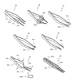
- the tweezers 8 and the like are held as objects to be held, but many types of tweezers 8A to 8G shown in FIG.
- the tweezers 8A has a first movable portion 8Ab and second and third movable portions 8Ac and 8Ad that open and close with respect to a fulcrum 8Aa.
- movable fingers 38A, 38B, and 38C may be provided for the movable portions 8Ab to 8Ad, respectively.
- the movable portion 8Ab may be moved by the finger 38A
- the movable portions 8Ac and 8Ad may be moved by one finger 38B.
- the tweezers 8A at least one of the three movable portions 8Ab, 8Ac, and 8Ad may be movable, and the other movable portions may be fixed.
- the fixed movable portion can also be called a fixed portion.
- at least one movable part may be moved by one movable finger 38A and the other fixed part may be supported by another finger 38B.
- the other fixing portion of the tweezers 8A may be supported by the fixing portion 44 or the like, in which case the separate finger 38B can be omitted.
- tweezers having four or more movable parts can be held.
- the tweezers 8B has insulating tip portions 8Bd and 8Be, and can grip a semiconductor chip or the like.
- the tweezers 8C have flat tip portions 8Cd and 8Ce, and can easily grip special-shaped parts such as spherical parts.
- the tweezers 8D has ring-shaped tips 8Dd and 8De, and can easily grip objects such as small jewels and grains of rice.
- the tweezers 8E have narrow, downwardly curved tips 8Ed and 8Ee, which can easily grip thin parts such as washers and shim rings.
- the tip parts 8Fd and 8Fe move in opposite directions.
- the counteracting tweezers 8F can be used, for example, to support the O-ring OBR from the inside (gripping from the inside to the outside).
- the bamboo tweezers 8G has movable parts 8Gb and 8Gc made of bamboo fixed to both ends of a fulcrum member 8Ga, and can be used to grip delicate parts such as lenses. It should be noted that other tweezers having an arbitrary shape and an arbitrary application can be held as objects to be held by the tweezer holding portion 26 .
- any tool or fixture having a plurality of movable parts that move about a fulcrum (or a fulcrum portion) such as scissors 9A to tweezers type chip remover 9I in FIG. 15 is possible.
- scissors 9A can cut an object by moving two arc-shaped movable parts 9Ab and 9Ac connected by a connecting part 9Aa around a fulcrum 9Ad so that cutting edges 9Ae and 9Af move in opposite directions.
- the tweezers 9B have flared tips and can be used for tweezing, fish boning, or thorn removal.
- the portable tweezers 9C has distal end portions 9Cb. It has a 9Cc and can be lengthened in use.
- the tweezers-type chopsticks 9D are obtained by fixing the thick ends of two wooden chopsticks 9Db and 9Dc to an elastic fulcrum portion 9Da, and can be used, for example, to hold foodstuffs for nursing care.
- the tweezers 9E with a magnifying glass have a magnifying lens 9Ed attached in the middle of the movable parts 9Eb and 9Ec that move about the fulcrum 9Ea, and can be used for repairing precision machinery.
- the tweezers type tongs 9F can be used for moving food materials.
- the tweezers type tester 9G includes a fulcrum portion 9Ga and a movable portion 9Gb. It has 9Gc and conductive pins 9Gd and 9Ge provided at the tips of the movable parts 9Gb and 9Gc, and can be used for inspection of electronic circuits and the like.
- the tweezers-type probe 9H includes a fulcrum portion 9Ha and a movable portion 9Hb. 9Hc, conductive probes 9Hd and 9He provided at the tips of the movable parts 9Hb and 9Hc, and signal lines connecting the probes 9Hd and 9He to an external inspection device.
- the tweezers type probe 9H can also be used for inspection of electronic circuits and the like.
- the tweezers type tip remover 9I has two movable parts 9Ib and 9Ic rotatable about a fulcrum 9Ia, and heating parts 9Id and 9Ie provided at the tips of the movable parts 9Ib and 9Ic. Semiconductor chips and parts soldered in electronic circuits can be removed by the tweezers type chip remover 9I.
- the robot hand 6D includes a hand main body 28 having a joint portion 30, an operating portion 32, a damping mechanism 34, and a first connecting portion 36, fingers 38A and 38B driven by the operating portion 32, and a tweezers holding portion 26.
- the tweezers holding part 26 of this modified example holds a loupe-equipped tweezers 9E to which a lens 9Ed is attached.
- the imaging device 22 and the illumination device 24 are attached to the +X direction side surface of the operation unit 32 .
- Other configurations are similar to those of the first embodiment.
- a lens 9Ed is arranged between the imaging device 22 and the tip of the tweezers 9E (object OB). Further, the focal plane A through the lens 9Ed of the imaging device 22 is set near the plane including the object OB, and the focal plane B without the lens 9Ed is set on the back side of the object OB.
- the imaging signal of the peripheral portion of the field of view of the imaging device 22 it is possible to roughly recognize the outer state of the object OB and the tip of the tweezers 9E.
- the relative position between the tip of the tweezers 9E and the object OB can be detected with high accuracy in an enlarged state. Therefore, the tip of the tweezers 9E and the object OB can be aligned with higher accuracy.
- the robot hands 6 to 6D are joined to the vertical articulated robot device 2.
- the robot device 2 to which the robot hands 6 to 6D are joined may be installed on a wall surface, a ceiling, or a position suitable for work such as factory equipment, in addition to the floor surface of the room.
- the robot hands 6 to 6D described above can be connected to various other robot devices shown in FIGS. 17(A) to (C).
- the horizontal multi-joint type (scalar type) robot apparatus 2A shown in FIG. 17A can particularly move in the horizontal direction and in the vertical direction (vertical direction) at high speed.
- the orthogonal robot device 2C shown in FIG. 17C is capable of moving the robot hand 6 in three orthogonal axial directions.
- the portion to which the robot hand 6 is joined can be regarded as a robot arm.
- the robot hands 6A to 6D can also be jointed to the robot devices 2A to 2C.
- robot hands of the above-described embodiments are not limited to the above-described robot devices, and can be applied to various robot devices (eg, assembly robots, human-collaborative robots, etc.) having joint structures such as other robot arms.
- various robot devices eg, assembly robots, human-collaborative robots, etc.
Landscapes
- Engineering & Computer Science (AREA)
- Robotics (AREA)
- Mechanical Engineering (AREA)
- Manipulator (AREA)
Abstract
A robot hand device that can be joined to a robot arm is provided, comprising: a body portion that can be joined to the robot arm; a holding portion capable of holding a tweezers-type tool capable of supporting an object by means of a plurality of contact portions that relatively open and close with respect to a fulcrum and of which at least one is movable; a coupling portion that couples the holding portion to the body portion; and at least one finger portion actuated by the body portion to open and close the plurality of contact portions of the tweezers-type tool in a state of being held by the holding portion. Objects of various shapes can be easily gripped, supported, or operated.
Description
本発明は、例えばロボットハンド装置、ロボットハンド装置を備えたロボット装置、並びにロボットハンド装置及びロボット装置の制御方法に関する。
The present invention relates to, for example, a robot hand device, a robot device equipped with the robot hand device, and a control method for the robot hand device and the robot device.
対象物を把持するためのロボットハンドを有し、ロボットハンドと対象物とを撮像し、撮像結果から両者間の位置ずれ量を補正可能なロボットが使用されている(例えば、引用文献1参照)。かかる技術においては、種々の対象物を容易に把持、支持、または操作できることが望まれている。
A robot that has a robot hand for gripping an object, captures an image of the robot hand and the object, and is capable of correcting the amount of positional deviation between the two from the imaging result is used (for example, see Cited Document 1). In such technology, it is desired that various objects can be easily grasped, supported, or manipulated.
本発明の第1の態様によれば、ロボットアームに接合可能なロボットハンド装置であって、そのロボットアームに接合可能な本体部と、支点に関して相対的に開閉する、少なくとも1つが可動である複数の接触部で対象物を支持可能なピンセット式工具を保持可能な保持部と、その保持部をその本体部に対して連結する連結部と、その保持部に保持されている状態のそのピンセット式工具の複数のその接触部を開閉させるように、その本体部に作動される少なくとも1つのフィンガー部と、を備えるロボットハンド装置が提供される。
According to the first aspect of the present invention, there is provided a robot hand device connectable to a robot arm, comprising: a main body connectable to the robot arm; a holding part capable of holding a tweezers-type tool capable of supporting an object with a plurality of contact parts, at least one of which is relatively movable with respect to a fulcrum; a connecting part connecting the holding part to the main body; A robotic hand device is provided comprising:
第2の態様によれば、本発明の態様のロボットハンド装置と、そのロボットハンド装置の本体部が接合されるロボットアームと、そのロボットアームを駆動する駆動部と、を備えるロボット装置が提供される。
第3の態様によれば、ロボットアームに連結可能なロボットハンド装置の制御方法であって、支点に関して相対的に開閉する、少なくとも1つが可動である複数の接触部で対象物を支持可能なピンセット式工具をそのロボットハンド装置の保持部で保持させることと、そのロボットハンド装置の本体部に対してその保持部を連結することと、そのロボットハンド装置の少なくとも1つフィンガー部の作動によって、その保持部に保持されている状態のそのピンセット式工具の複数のその接触部を位置決めすることと、その保持部に保持されている状態のそのピンセット式工具の複数のその接触部を、そのフィンガー部によって開閉させて、複数のその接触部によって対象物を支持させることと、を含む制御方法が提供される。 According to a second aspect, there is provided a robot device comprising the robot hand device according to the aspect of the present invention, a robot arm to which the main body of the robot hand device is joined, and a drive section for driving the robot arm.
According to a third aspect, there is provided a method for controlling a robot hand device connectable to a robot arm, comprising: holding a tweezers-type tool capable of supporting an object with a plurality of contact portions, at least one of which is movable relative to a fulcrum, by a holding portion of the robot hand device; connecting the holding portion to a main body portion of the robot hand device; opening and closing the plurality of contact portions of the tweezers-type tool held by the holding portion by means of the finger portions to support an object by the plurality of contact portions.
第4の態様によれば、本発明の態様のロボットハンド装置と、ロボットアームと、そのロボットアームを駆動する駆動部と、を備えるロボット装置の制御方法であって、そのロボットハンド装置の本体部をそのロボットアームに接合することと、そのロボットアームに接合された本体部に、そのピンセット式工具を保持する保持部を連結することと、その保持部に保持された状態のそのピンセット式工具で対象物を支持可能な位置に、そのロボットアームを介してそのロボットハンド装置を移動することと、そのロボットハンド装置のフィンガー部を作動させて、そのピンセット式工具の複数の接触部でその対象物を支持させることと、そのロボットアームを介してそのロボットハンド装置を駆動してその対象物を操作することと、そのロボットハンド装置のフィンガー部を作動させて、そのピンセット式工具の複数の接触部からその対象物を離脱させることと、を含む制御方法が提供される。
According to a fourth aspect, there is provided a control method for a robot device comprising the robot hand device of the aspect of the present invention, a robot arm, and a drive unit for driving the robot arm. actuating the finger portions of the robot hand device to support the object with the plurality of contact portions of the tweezers type tool; driving the robot hand device via the robot arm to manipulate the object; and actuating the finger portions of the robot hand device to release the object from the plurality of contact portions of the tweezers type tool.
[第1の実施形態]
以下、第1の実施形態につき図1~図11を参照して説明する。
図1(A)は本実施形態の垂直多関節型のロボット装置2を示す。図1(A)において、ロボット装置2の設置面に平行に直交するX軸及びY軸を取り、その設置面に垂直にZ軸を取って説明する。一例としてその設置面はほぼ水平面であり、設置面の上方(鉛直方向の逆方向)をZ軸の+方向とする。 [First Embodiment]
A first embodiment will be described below with reference to FIGS. 1 to 11. FIG.
FIG. 1A shows a vertically articulatedrobot device 2 of this embodiment. In FIG. 1(A), the X-axis and the Y-axis which are parallel and perpendicular to the installation surface of the robot device 2 are taken, and the Z-axis is taken perpendicular to the installation surface. As an example, the installation surface is substantially horizontal, and the upper side of the installation surface (opposite direction to the vertical direction) is the + direction of the Z axis.
以下、第1の実施形態につき図1~図11を参照して説明する。
図1(A)は本実施形態の垂直多関節型のロボット装置2を示す。図1(A)において、ロボット装置2の設置面に平行に直交するX軸及びY軸を取り、その設置面に垂直にZ軸を取って説明する。一例としてその設置面はほぼ水平面であり、設置面の上方(鉛直方向の逆方向)をZ軸の+方向とする。 [First Embodiment]
A first embodiment will be described below with reference to FIGS. 1 to 11. FIG.
FIG. 1A shows a vertically articulated
図1(A)において、ロボット装置2は、ロボット本体部4と、ロボット本体部4に接合されたロボットハンド6と、ロボット本体部4の動作を制御する制御装置10と、ロボットハンド6の動作を制御する制御装置12とを備えている。ロボット本体部4は、ベース部14と、ベース部14に順に変位可能に連結された第1のロボットアーム18A、第2のロボットアーム18B、及び第3のロボットアーム18Cとを備えている。そして、第3のロボットアーム18Cの先端部20Aにロボットハンド6が接合されている。ロボットハンド6はエンドエフェクタとも呼ぶことができる。
In FIG. 1(A), the robot apparatus 2 includes a robot main body 4, a robot hand 6 joined to the robot main body 4, a control device 10 that controls the operation of the robot main body 4, and a control device 12 that controls the operation of the robot hand 6. The robot main body 4 includes a base portion 14, and a first robot arm 18A, a second robot arm 18B, and a third robot arm 18C which are connected to the base portion 14 in order so as to be displaceable. A robot hand 6 is joined to the distal end portion 20A of the third robot arm 18C. The robot hand 6 can also be called an end effector.
一例として、第1のロボットアーム18Aは、回転角θ1及び旋回角φ1が制御可能であり、第2のロボットアーム18Bは、回転角θ2及び旋回角φ2が制御可能であり、第3のロボットアーム18Cは、回転角θ3及び旋回角φ3が制御可能である。また、第3のロボットアーム18Cは、先端部20Aの回転角θ3を変化させる回転部20B及び旋回角φ3を変化させる傾斜駆動部20Cを有する。回転部20B及び傾斜駆動部20Cはそれぞれ駆動用モータ及び回転角を検出するエンコーダを有する。他のロボットアーム18A,18Bも同様の駆動部を有する。このため、第3のロボットアーム18Cに接合されたロボットハンド6は、X方向、Y方向、Z方向の位置、及び3軸の回りの回転角を含む6自由度の位置(角度を含む)が制御可能である。
As an example, the first robot arm 18A can control the rotation angle θ1 and the turning angle φ1, the second robot arm 18B can control the rotation angle θ2 and the turning angle φ2, and the third robot arm 18C can control the rotation angle θ3 and the turning angle φ3. Further, the third robot arm 18C has a rotating portion 20B that changes the rotation angle θ3 of the distal end portion 20A and an inclination driving portion 20C that changes the turning angle φ3. The rotating portion 20B and the tilt driving portion 20C each have a driving motor and an encoder for detecting the rotation angle. The other robot arms 18A, 18B have similar drives. Therefore, the robot hand 6 joined to the third robot arm 18C can control the position (including the angle) with six degrees of freedom including the positions in the X, Y and Z directions and rotation angles around three axes.
また、ロボット装置2は、撮像装置22及び照明装置24を備えている。一例として、撮像装置22及び照明装置24はロボットハンド6に装着されているが、撮像装置22及び照明装置24はロボットハンド6以外の位置、例えばロボットアーム18Cの先端部20A、ロボット装置2の設置面上の測定位置等、又はロボット装置2が設置されている部屋の壁や天井等に設けてもよい。
また、本実施形態のロボットハンド6はピンセット8を保持している。ピンセット8は市販、特注、自作、又は市販品を加工したもの等の任意のピンセットでよい。すなわち、ピンセット8は、図1(B)に拡大して示すように、支点8aに関して開閉可能に製造された1対のそれぞれ可撓性を持つ細長い平板状の可動部(接触部又は開閉部)8b及び8cを有する。そして、ピンセット8の支点8aと可動部8b,8cの先端の作用点8d,8eとのほぼ中間の力点8bF,8cFを内側に押すことによって、可動部8b,8cが閉じて作用点8d,8e間に対象物OBを把持又は支持することができる。また、力点8bF,8cFを押す力を減少させることで、可動部8b,8cが開いて対象物OBを離脱させることができる。一例として、ロボットハンド6はピンセット8の支点8aを保持している。 Therobot device 2 also includes an imaging device 22 and an illumination device 24 . As an example, the imaging device 22 and the lighting device 24 are attached to the robot hand 6, but the imaging device 22 and the lighting device 24 may be provided at positions other than the robot hand 6, such as the distal end 20A of the robot arm 18C, the measurement position on the installation surface of the robot device 2, or the wall or ceiling of the room where the robot device 2 is installed.
Further, therobot hand 6 of this embodiment holds tweezers 8 . The tweezers 8 may be any tweezers such as commercially available, custom made, home made, or modified from commercially available products. That is, the tweezers 8, as shown enlarged in FIG. 1(B), has a pair of flexible elongated flat plate-like movable parts (contact parts or opening/closing parts) 8b and 8c that are manufactured to be openable and closable with respect to the fulcrum 8a. By pushing inwardly force points 8bF and 8cF substantially intermediate between the fulcrum 8a of the tweezers 8 and the points of action 8d and 8e at the tips of the movable parts 8b and 8c, the movable parts 8b and 8c are closed and the object OB can be gripped or supported between the points of action 8d and 8e. Also, by reducing the force that pushes the power points 8bF and 8cF, the movable portions 8b and 8c can be opened to release the object OB. As an example, the robot hand 6 holds the fulcrum 8 a of the tweezers 8 .
また、本実施形態のロボットハンド6はピンセット8を保持している。ピンセット8は市販、特注、自作、又は市販品を加工したもの等の任意のピンセットでよい。すなわち、ピンセット8は、図1(B)に拡大して示すように、支点8aに関して開閉可能に製造された1対のそれぞれ可撓性を持つ細長い平板状の可動部(接触部又は開閉部)8b及び8cを有する。そして、ピンセット8の支点8aと可動部8b,8cの先端の作用点8d,8eとのほぼ中間の力点8bF,8cFを内側に押すことによって、可動部8b,8cが閉じて作用点8d,8e間に対象物OBを把持又は支持することができる。また、力点8bF,8cFを押す力を減少させることで、可動部8b,8cが開いて対象物OBを離脱させることができる。一例として、ロボットハンド6はピンセット8の支点8aを保持している。 The
Further, the
なお、ピンセット8は一方の可動部8bが固定され、他方の可動部8cのみが可動であってもよい。すなわち、可動部8b,8cは相対的に開閉可能であればよい。また、ピンセット8の代わりに、接触部(可動部)が3本以上あるピンセットを使用することもできる。この際に、その3本以上の接触部のうち少なくとも1つの接触部のみが可動で、他の接触部が固定されていてもよい。
図2(A)は図1(A)中のロボットハンド6を示し、図2(A)は、ロボットハンド6が、Z軸に平行なロボットアーム18Cの先端部20Aの下端に、保持しているピンセット8の可動部の開閉方向がY軸に平行な方向(Y方向)になるように接合された状態を示している。図2(A)において、ロボットハンド6は、先端部20Aの下端に接合されたハンド本体部28と、ハンド本体部28に連結されてピンセット8を保持するピンセット保持部26と、ピンセット保持部26に保持されたピンセット8の可動部の開閉を行う一対のフィンガー38A,38Bとを備えている。 Thetweezers 8 may be fixed at one movable portion 8b and movable only at the other movable portion 8c. That is, the movable parts 8b and 8c need only be relatively openable and closable. Also, instead of the tweezers 8, tweezers having three or more contact portions (movable portions) can be used. At this time, only at least one contact portion among the three or more contact portions may be movable, and the other contact portions may be fixed.
FIG. 2(A) shows therobot hand 6 in FIG. 1(A), and FIG. 2(A) shows a state in which the robot hand 6 is joined to the lower end of the tip portion 20A of the robot arm 18C parallel to the Z-axis so that the opening/closing direction of the movable portion of the tweezers 8 held is parallel to the Y-axis (Y-direction). 2A, the robot hand 6 includes a hand main body 28 joined to the lower end of the tip 20A, a tweezers holding part 26 connected to the hand main body 28 and holding the tweezers 8, and a pair of fingers 38A and 38B for opening and closing the movable part of the tweezers 8 held by the tweezers holding part 26.
図2(A)は図1(A)中のロボットハンド6を示し、図2(A)は、ロボットハンド6が、Z軸に平行なロボットアーム18Cの先端部20Aの下端に、保持しているピンセット8の可動部の開閉方向がY軸に平行な方向(Y方向)になるように接合された状態を示している。図2(A)において、ロボットハンド6は、先端部20Aの下端に接合されたハンド本体部28と、ハンド本体部28に連結されてピンセット8を保持するピンセット保持部26と、ピンセット保持部26に保持されたピンセット8の可動部の開閉を行う一対のフィンガー38A,38Bとを備えている。 The
FIG. 2(A) shows the
また、ハンド本体部28は、先端部20Aに接合された平板状の接合部(ジョイント)30と、接合部30に固定されてフィンガー38A,38BをY方向に移動させる作動部32と、作動部32の-X方向の側面にダンピング機構34(詳細後述)を介して固定された円板状の第1連結部36とを有する。接合部30は、先端部20Aに対して機械的(ねじによる固定、可動の爪機構による固定、永久磁石による固定等)、又は電気的(電磁石による固定等)に接合されている。さらに、接合部30には、必要に応じて電気配線、圧縮空気の配管、及び/又は真空吸着用の配管等の接続部が設けられている。接合部30には先端部20Aに対する位置及び回転角が所定値になるように複数の凸部又は凹部等の位置決め部(不図示)が設けられている。
The hand main body 28 also has a flat joint 30 joined to the tip 20A, an operating section 32 that is fixed to the joint 30 and moves the fingers 38A and 38B in the Y direction, and a disk-shaped first connecting section 36 that is fixed to the -X direction side surface of the operating section 32 via a damping mechanism 34 (details will be described later). The joint portion 30 is mechanically (fixed by a screw, fixed by a movable claw mechanism, fixed by a permanent magnet, etc.) or electrically (fixed by an electromagnet, etc.) to the distal end portion 20A. Further, the joint 30 is provided with a connecting portion such as an electric wiring, a compressed air pipe, and/or a vacuum suction pipe as required. The joining portion 30 is provided with positioning portions (not shown) such as a plurality of protrusions or recesses so that the position and the rotation angle with respect to the tip portion 20A have predetermined values.
また、ピンセット保持部26は、ハンド本体部28の第1連結部36に着脱可能に連結される円板状の第2連結部40と、第2連結部40に対してZ軸に平行な軸の回りに所定範囲(例えば数度)で回転可能に固定された回転部42と、回転部42の底面に固定された固定部44と、固定部44の一面にピンセット8の支点8aを挟み込んで固定するための押さえ部46とを有する。一例として、固定部44の一面に配置したピンセット8の支点8aを押さえ部46で覆い(図4(B)参照)、複数のボルトB1で押さえ部46を固定部44に固定することで、固定部44にピンセット8の支点8aを固定してピンセット8を安定に保持できる。この際に、ピンセット8の可動部8b,8cの先端(作用点8d,8e)はフィンガー38A,38B間を通してフィンガー38A,38Bの+X方向に突き出ている。なお、ピンセット8の保持方法としては、固定部44にピンセット8の支点8aを置き、その上から板ばね等で押さえる方法、又はダブルクリップ等の把持具を用いてピンセット8の支点又はその他の部分を固定する方法なども使用できる。
The tweezers holding part 26 includes a disk-shaped second connecting part 40 that is detachably connected to the first connecting part 36 of the hand main body 28, a rotating part 42 that is rotatable within a predetermined range (for example, several degrees) around an axis parallel to the Z-axis with respect to the second connecting part 40, a fixed part 44 that is fixed to the bottom surface of the rotating part 42, and a holding part 46 that holds and fixes the fulcrum 8a of the tweezers 8 on one surface of the fixed part 44. and As an example, by covering the fulcrum 8a of the tweezers 8 arranged on one surface of the fixed portion 44 with the holding portion 46 (see FIG. 4B) and fixing the holding portion 46 to the fixed portion 44 with a plurality of bolts B1, the fulcrum 8a of the tweezers 8 can be fixed to the fixed portion 44 and the tweezers 8 can be stably held. At this time, the tips ( action points 8d and 8e) of the movable portions 8b and 8c of the tweezers 8 protrude in the +X direction of the fingers 38A and 38B through between the fingers 38A and 38B. As a method for holding the tweezers 8, a method of placing the fulcrum 8a of the tweezers 8 on the fixing portion 44 and holding down with a leaf spring or the like from above, or a method of fixing the fulcrum of the tweezers 8 or other parts using a gripping tool such as a double clip can be used.
また、第1連結部36と第2連結部40とは、一例として第1連結部36及び第2連結部40内に設けられた永久磁石によって切り離し可能に連結される。例えば第1連結部36の底面に複数の凸部36aが設けられ、第2連結部40の上面にそれらに応じた凹部40bが設けられ(図4(A)参照)、凸部36aと凹部40bとを合わせて連結部36,40を連結することで、第1連結部36(ハンド本体部28)に対する第2連結部40(ピンセット保持部26)の回転角を設定値に合わせることができる。なお、第1連結部36に対する第2連結部40の着脱可能の連結方法としては、可動の爪機構等で機械的に連結する方法、電磁石で連結する方法、又は真空吸着による連結方法等も使用できる。
In addition, the first connecting portion 36 and the second connecting portion 40 are detachably connected by permanent magnets provided in the first connecting portion 36 and the second connecting portion 40, for example. For example, a plurality of convex portions 36a are provided on the bottom surface of the first connecting portion 36, and corresponding concave portions 40b are provided on the upper surface of the second connecting portion 40 (see FIG. 4A). As a method for detachably connecting the second connecting portion 40 to the first connecting portion 36, a method of mechanically connecting with a movable pawl mechanism or the like, a method of connecting with an electromagnet, a method of connecting by vacuum suction, or the like can be used.
また、ピンセット保持部26の第2連結部40にはU字型の溝部40a(図2(D)参照)が設けられている。後述のピンセットスタンド64の架台64a(図8(A)参照)に溝部40aを合わせて第2連結部40をピンセットスタンド64の凹部64bに設置することで、回転角を合わせた状態でピンセットスタンド64にピンセット保持部26を設置(格納)できる。この際に、予め固定部44と押さえ部46との間に互いに形状の異なるピンセットを固定した複数のピンセット保持部26を用意して、ピンセットスタンド64に設置しておいてもよい。そして、ロボットハンド6を移動して第1連結部36と第2連結部40との切り離し及び連結を行うだけで、ロボットハンド6で保持されているピンセット(ピンセット保持部26)を対象物に応じたピンセットに容易に交換できる。以下、ピンセット8を保持した状態のピンセット保持部26をピンセットユニット27とも称する。
In addition, a U-shaped groove portion 40a (see FIG. 2(D)) is provided in the second connecting portion 40 of the tweezers holding portion 26. As shown in FIG. By aligning the groove portion 40a with a base 64a (see FIG. 8A) of the tweezers stand 64, which will be described later, and installing the second connecting portion 40 in the concave portion 64b of the tweezers stand 64, the tweezers holding portion 26 can be installed (stored) in the tweezers stand 64 with the rotation angle adjusted. At this time, a plurality of tweezers holding portions 26 in which tweezers having different shapes are fixed between the fixing portion 44 and the pressing portion 46 may be prepared in advance and installed on the tweezers stand 64 . Then, only by moving the robot hand 6 to separate and connect the first connecting part 36 and the second connecting part 40, the tweezers (tweezers holding part 26) held by the robot hand 6 can be easily replaced with tweezers corresponding to the object. Hereinafter, the tweezers holding portion 26 holding the tweezers 8 is also referred to as a tweezers unit 27 .
図2(C)は図2(A)の側面図であり、図2(C)において、作動部32は、回転モータ部32aと、回転モータ部32aの回転量を減速して直線運動に変換する変換部32bとを有する。回転モータ部32aは、回転角(フィンガー38A,38Bの移動量)を検出するエンコーダ、及びステッピングモータ又はDCモータ等から構成されている。作動部32によって、1対のフィンガー38A,38Bは、ピンセット8の可動部8b,8cの開閉方向(ここではY方向)の間隔を開閉するために、Y方向の間隔が減少又は増大するように移動する。すなわち、フィンガー38A,38Bの内側には例えば半球体状の突部38Aa,38Baが設けられ、突部38Aa,38Baがピンセット8の可動部8b,8cの力点(又は支点8aと作用点8d,8eとの間の点)に接触して可動部8b,8cを+Y方向及び-Y方向に押すことによって、可動部8b,8cの間隔が小さくなり(可動部8b,8cが閉じて)、可動部8b,8cの先端の作用点8d,8e間に対象物OBを把持し、挟み、又は支持できる。その後、突部38Aa,38Baを-Y方向及び+Y方向に移動させることによって、可動部8b,8cの間隔が大きくなり(可動部8b,8cが開いて)、ピンセット8を対象物OBから離脱させることができる。なお、フィンガー38A,38Bが互いに独立にY方向に移動するように作動させてもよい。
FIG. 2(C) is a side view of FIG. 2(A). In FIG. 2(C), the operating portion 32 has a rotary motor portion 32a and a conversion portion 32b that reduces the amount of rotation of the rotary motor portion 32a and converts it into linear motion. The rotary motor section 32a is composed of an encoder for detecting a rotation angle (amount of movement of the fingers 38A and 38B), a stepping motor, a DC motor, or the like. The actuating portion 32 causes the pair of fingers 38A, 38B to move so as to decrease or increase the Y-direction spacing in order to open or close the spacing of the movable portions 8b, 8c of the tweezers 8 in the opening/closing direction (here, the Y-direction). That is, for example, hemispherical protrusions 38Aa and 38Ba are provided inside the fingers 38A and 38B, and the protrusions 38Aa and 38Ba come into contact with the points of force of the movable portions 8b and 8c of the tweezers 8 (or the points between the fulcrum 8a and the points of action 8d and 8e) and push the movable portions 8b and 8c in the +Y direction and the −Y direction. closed), the object OB can be gripped, pinched, or supported between action points 8d and 8e at the tips of the movable parts 8b and 8c. Thereafter, by moving the projecting portions 38Aa and 38Ba in the -Y direction and +Y direction, the distance between the movable portions 8b and 8c is increased (the movable portions 8b and 8c are opened), and the tweezers 8 can be separated from the object OB. Alternatively, the fingers 38A and 38B may be operated to move independently of each other in the Y direction.
また、対象物を把持又は支持していない状態では、一例として-Y方向のフィンガー38AはY方向の可動範囲内で最も外側(-Y方向)の位置(以下、待機位置ともいう)に待機しており、+Y方向のフィンガー38BはY方向の可動範囲内で最も外側(+Y方向)の位置(以下、待機位置ともいう)に待機している。ピンセット8で対象物を把持する際にはフィンガー38A,38Bは待機位置からピンセット8の可動部8b,8c側に移動し、対象物からピンセット8を離す際にはフィンガー38A,38Bは可動部8b,8cから待機位置に移動する。
In addition, when the object is not gripped or supported, as an example, the -Y direction finger 38A is on standby at the outermost (-Y direction) position (hereinafter also referred to as the standby position) within the Y direction movable range, and the +Y direction finger 38B is on standby at the outermost (+Y direction) position (hereinafter also referred to as the standby position) within the Y direction movable range. When the tweezers 8 grip the object, the fingers 38A, 38B move from the standby position to the movable parts 8b, 8c of the tweezers 8, and when the tweezers 8 are released from the object, the fingers 38A, 38B move from the movable parts 8b, 8c to the standby position.
さらに、フィンガー38A,38Bの突部38Aa,38Baは、一例として摩擦抵抗の小さい材料(例えばテフロン(登録商標)など)から形成されている。このため、ピンセット保持部26で保持されているピンセット8は、フィンガー38A,38Bに対してZ方向やX方向に微少量動く(滑る)ことができる。なお、突部38Aa,38Baの形状は、Z方向に長い半楕円体状、又はZ方向に長いカマボコ状等であってもよい。また、突部38Aa,38Baの材料は、必ずしも摩擦抵抗の小さい材料には限定されない。
Furthermore, the projections 38Aa and 38Ba of the fingers 38A and 38B are made of, for example, a material with low frictional resistance (such as Teflon (registered trademark)). Therefore, the tweezers 8 held by the tweezers holding portion 26 can slightly move (slide) in the Z and X directions with respect to the fingers 38A and 38B. The shape of the protrusions 38Aa and 38Ba may be a semi-elliptical shape that is long in the Z direction, or a semicylindrical shape that is long in the Z direction. Also, the material of the protrusions 38Aa and 38Ba is not necessarily limited to a material with low frictional resistance.
また、図2(B)はロボットハンド6の制御装置12を示す。制御装置12は、図1(A)の制御装置10との間での制御情報(GI,MC)の送受、及び装置全体の動作の制御を行うハンド制御部48Aと、作動部32を介してフィンガー38A,38Bの動きを制御するフィンガー制御部48Bと、フィンガー38A,38Bに対するピンセット8の可動部8b,8cからの反力(フィンガー38A,38Bによる力)をフィンガー把持力FFとして検出するフィンガー把持力検出部48Cと、各種データを記憶する記憶部48Dとを有する。制御装置12に入力される制御情報GIは、例えばピンセット8による対象物の把持開始命令及び把持解除命令を含み、制御装置12から制御装置10に出力される制御情報MCは、例えばピンセット8による対象物の把持完了を示す情報、及びピンセット8による対象物の把持の解除の完了(対象物からのピンセットの離脱の完了)を示す情報を含む。
Also, FIG. 2(B) shows the control device 12 of the robot hand 6 . The control device 12 includes a hand control unit 48A that transmits and receives control information (GI, MC) to and from the control device 10 of FIG. 1A and controls the operation of the entire device, a finger control unit 48B that controls the movement of the fingers 38A and 38B via the operation unit 32, and reaction forces (forces by the fingers 38A and 38B) from the movable portions 8b and 8c of the tweezers 8 against the fingers 38A and 38B as a finger gripping force FF. It has a finger gripping force detection unit 48C for detecting, and a storage unit 48D for storing various data. The control information GI input to the control device 12 includes, for example, an instruction to start gripping the object by the tweezers 8 and an instruction to release the gripping of the object, and the control information MC output from the control device 12 to the control device 10 includes, for example, information indicating completion of gripping the object by the tweezers 8 and information indicating completion of releasing the grip of the object by the tweezers 8 (completion of detachment of the tweezers from the object).
記憶部48Dは、例えば、HDD(Hard Disk Drive)やSSD(Solid State Drive)等の記憶装置、及びUSB(Universal Serial Busメモリ)等の不揮発性メモリのいずれかを含んでもよい。記憶部48Dは、制御装置12のプログラム、及び各種設定値等を記憶する。
一例として、フィンガー把持力検出部48Cは、作動部32の回転モータ部32aに流れる電流からフィンガー把持力FFを検出し、フィンガー制御部48Bはその検出されるフィンガー把持力FFが予め設定されているレベル(規格値)以下になるようにフィンガー38A,38Bの動作を制御する。これによって、ピンセット8、フィンガー38A,38B、及び/又は対象物の破損等を防止できる。なお、フィンガー把持力検出部48Cの代わりに、例えばフィンガー38A,38Bに設けた歪みゲージ、又は圧力センサ等のフィンガー把持力FFを検出可能なセンサを使用できる。 Thestorage unit 48D may include, for example, a storage device such as a HDD (Hard Disk Drive) or an SSD (Solid State Drive), or a non-volatile memory such as a USB (Universal Serial Bus memory). The storage unit 48D stores programs of the control device 12, various setting values, and the like.
As an example, the finger grippingforce detection unit 48C detects the finger gripping force FF from the current flowing through the rotary motor unit 32a of the operating unit 32, and the finger control unit 48B controls the operations of the fingers 38A and 38B so that the detected finger gripping force FF is equal to or lower than a preset level (standard value). This can prevent damage to the tweezers 8, the fingers 38A and 38B, and/or the object. Instead of the finger gripping force detection unit 48C, for example, strain gauges provided on the fingers 38A and 38B, or sensors capable of detecting the finger gripping force FF, such as pressure sensors, can be used.
一例として、フィンガー把持力検出部48Cは、作動部32の回転モータ部32aに流れる電流からフィンガー把持力FFを検出し、フィンガー制御部48Bはその検出されるフィンガー把持力FFが予め設定されているレベル(規格値)以下になるようにフィンガー38A,38Bの動作を制御する。これによって、ピンセット8、フィンガー38A,38B、及び/又は対象物の破損等を防止できる。なお、フィンガー把持力検出部48Cの代わりに、例えばフィンガー38A,38Bに設けた歪みゲージ、又は圧力センサ等のフィンガー把持力FFを検出可能なセンサを使用できる。 The
As an example, the finger gripping
次に、図2(A)中のダンピング機構34は、図3(A)及び(B)に示すように、作動部32の-X方向側の側面に固定されて対向する2つの平板部50a,50bを有する支持部材50と、支持部材50の間から第1連結部36まで伸びるブリッジ部材51と、平板部50a,50b間にブリッジ部材51を貫通するように設けられた2本の円柱状のスライド軸52A,52Bと、スライド軸52A,52Bを収容するようにブリッジ部材51に固定されたリニアベアリング53A,53Bとを有する。リニアベアリング53A,53Bによって、ブリッジ部材51は支持部材50の2つの平板部50a,50bの間を円滑にZ方向に移動(変位)できる。ブリッジ部材51には第1連結部36が固定され、第1連結部36には第2連結部40を介してピンセット保持部26が連結されているため、ブリッジ部材51及び第1連結部36と連動してピンセット保持部26もZ方向に移動する。
Next, as shown in FIGS. 3(A) and 3(B), the damping mechanism 34 in FIG. 2(A) includes a support member 50 having two flat plate portions 50a and 50b that are fixed to the -X direction side of the operating portion 32 and face each other, a bridge member 51 that extends from between the support members 50 to the first connecting portion 36, and two cylindrical slide shafts 52A that are provided between the flat plate portions 50a and 50b so as to pass through the bridge member 51. 52B and linear bearings 53A, 53B fixed to the bridge member 51 so as to accommodate the slide shafts 52A, 52B. The linear bearings 53A and 53B allow the bridge member 51 to smoothly move (displace) between the two flat plate portions 50a and 50b of the support member 50 in the Z direction. Since the first connecting portion 36 is fixed to the bridge member 51, and the tweezers holding portion 26 is connected to the first connecting portion 36 via the second connecting portion 40, the tweezers holding portion 26 also moves in the Z direction in conjunction with the bridge member 51 and the first connecting portion 36.
また、図3(A)に示すように、リニアベアリング53A,53Bと上方の平板部50bとの間に圧縮コイルばね54A,54Bが設置され、下方の平板部50aの上面及び上方の平板部50bの下面にそれぞれ所定長さのストッパーSTA,STBが設けられている。このため通常は、コイルばね54A,54Bの付勢力、並びにブリッジ部材51及びピンセット保持部26等の自重によってブリッジ部材51は下方(-Z方向)のストッパーSTA側に付勢されている。一方、ブリッジ部材51に+Z方向への力が加わった場合には、ブリッジ部材51は上方のストッパーSTB側に移動できる。ストッパーSTA,STBの間隔によってブリッジ部材51(ひいてはピンセット保持部26)のZ方向への移動量が規定されている。なお、コイルばね54A,54Bの代わりに他の弾性部材を使用してもよい。
Also, as shown in FIG. 3A, compression coil springs 54A and 54B are installed between the linear bearings 53A and 53B and the upper flat plate portion 50b, and stoppers STA and STB of predetermined lengths are provided on the upper surface of the lower flat plate portion 50a and the lower surface of the upper flat plate portion 50b, respectively. Therefore, normally, the bridge member 51 is biased downward (-Z direction) toward the stopper STA by the biasing force of the coil springs 54A and 54B and the weight of the bridge member 51, the tweezers holding portion 26, and the like. On the other hand, when a force in the +Z direction is applied to the bridge member 51, the bridge member 51 can move upward toward the stopper STB. The distance between the stoppers STA and STB defines the amount of movement of the bridge member 51 (and thus the tweezers holding portion 26) in the Z direction. Note that other elastic members may be used instead of the coil springs 54A and 54B.
本実施形態のダンピング機構34によって、ハンド本体部28の作動部32に対してピンセット保持部26が保持されている。この状態で、仮にピンセット保持部26が保持しているピンセット8の先端で保持されている対象物(不図示)や、この対象物が載置されている載物台(不図示)に+Z方向に必要以上の力が付与されると、その力を逃がすために、ダンピング機構34のブリッジ部材51(ピンセット保持部26)が支持部材50に対して+Z方向に移動する。このため、対象物や載物台に加わる力によって、対象物及びピンセット8の先端の変形等を防止することができる。さらに、フィンガー38A,38Bの突部38Aa,38Baはピンセット8に対して滑り易い材料で形成されているため、ピンセット保持部26がZ方向に移動する際に、その移動に連動してピンセット8はフィンガー38A,38Bの突部38Aa,38Baに対してZ方向に円滑に移動できる。
The damping mechanism 34 of this embodiment holds the tweezers holding portion 26 with respect to the operating portion 32 of the hand body portion 28 . In this state, if an object (not shown) held by the tips of the tweezers 8 held by the tweezers holding portion 26 or a table (not shown) on which the object is placed is subjected to a +Z direction force more than necessary, the bridge member 51 (tweezers holding portion 26) of the damping mechanism 34 moves in the +Z direction with respect to the support member 50 in order to release the force. Therefore, it is possible to prevent deformation of the object and the tip of the tweezers 8 due to the force applied to the object and the stage. Furthermore, since the protrusions 38Aa and 38Ba of the fingers 38A and 38B are made of a material that easily slides on the tweezers 8, when the tweezers holding section 26 moves in the Z direction, the tweezers 8 can move smoothly in the Z direction with respect to the protrusions 38Aa and 38Ba of the fingers 38A and 38B.
なお、ダンピング機構34の代わりに、図3(C)の変形例のロボットハンド6Aで示すように、板ばね等を使用した構成も使用可能である。図3(C)において、ロボットハンド6Aはハンド本体部28と第1連結部36とを連結するダンピング機構34Aを備えている。ダンピング機構34Aは、作動部32の-X方向側の側面に固定された平板状の支持部材50Aと、支持部材50Aと第1連結部36とを連結するZ方向に離れた複数枚(一例として2枚)の板ばね55と、支持部材50Aに設けられた-Z方向側のストッパーSTC及び+Z方向側のストッパーSTDとを有する。この他の構成は図2(A)と同様である。なお、板ばね55の代わりに他の弾性部材を使用してもよい。
It should be noted that instead of the damping mechanism 34, a configuration using a plate spring or the like can also be used, as shown by the modified robot hand 6A in FIG. 3(C). In FIG. 3C, the robot hand 6A has a damping mechanism 34A that connects the hand main body 28 and the first connecting portion 36. As shown in FIG. The damping mechanism 34A includes a flat support member 50A fixed to the −X direction side surface of the operating portion 32, a plurality of (two as an example) leaf springs 55 separated in the Z direction connecting the support member 50A and the first connecting portion 36, and a −Z direction side stopper STC and a +Z direction side stopper STD provided on the support member 50A. Other configurations are the same as those in FIG. It should be noted that other elastic members may be used instead of the leaf springs 55 .
ダンピング機構34Aによって、ハンド本体部28の作動部32に対してピンセット保持部26が保持されている。この状態で、ピンセット保持部26が保持しているピンセット8の先端で保持されている対象物や、この対象物が載置されている載物台に+Z方向に必要以上の力が付与されると、その力を逃がすために、板ばね55の弾性変形によって、第1連結部36(ピンセット保持部26)が支持部材50Aに対して+Z方向に移動する。このため、対象物や載物台に加わる力によって、対象物及びピンセット8の先端の変形等を防止することができる。さらに、対象物や載物台に加わる力によるフィンガー38A,38B(ピンセット保持部26)、ピンセット8、及び対象物の損傷を防止することもできる。
The tweezers holding portion 26 is held by the actuating portion 32 of the hand body portion 28 by the damping mechanism 34A. In this state, when an object held by the tips of the tweezers 8 held by the tweezers holding portion 26 and the stage on which the object is placed are subjected to a +Z direction force more than necessary, the elastic deformation of the leaf spring 55 causes the first connecting portion 36 (tweezers holding portion 26) to move in the +Z direction with respect to the support member 50A in order to release the force. Therefore, it is possible to prevent deformation of the object and the tip of the tweezers 8 due to the force applied to the object and the stage. Furthermore, it is possible to prevent damage to the fingers 38A and 38B (tweezers holding portion 26), the tweezers 8, and the object due to force applied to the object and the stage.
次に、図4(A)は図2(A)のピンセット保持部26及び作動部32の一部を示し、図4(B)及び(C)は図4(A)のAA線に沿う断面図である。なお、説明の便宜上、図4(A)は第2連結部40の溝部40aをピンセットスタンド64(図8(A)参照)の架台64aに挿入して、第2連結部40から第1連結部36を離脱させた状態を示している。以下では、第1連結部36に第2連結部40が連結されているものとして説明する。
Next, FIG. 4(A) shows a part of the tweezers holding portion 26 and the operating portion 32 of FIG. 2(A), and FIGS. 4(B) and (C) are cross-sectional views along line AA of FIG. 4(A). For convenience of explanation, FIG. 4A shows a state in which the groove portion 40a of the second connecting portion 40 is inserted into the base 64a of the tweezers stand 64 (see FIG. 8A), and the first connecting portion 36 is separated from the second connecting portion 40. In the following description, it is assumed that the second connecting portion 40 is connected to the first connecting portion 36 .
図4(A)及び(B)において、ピンセット保持部26の第2連結部40の底面のZ軸に平行なリニアガイド40cに、回転部42に設けられた回転軸受56が勘合している。このため、第2連結部40に対して回転部42は、Z軸に平行な軸の回りに円滑に回転可能である。回転部42の上面に凸部57が設けられ、第2連結部40の底面に凸部57を挟むようにストッパーSTE及びSTFが設けられている。ストッパーSTE及びSTFによって、回転部42の回転可能な角度範囲が所定角度範囲(例えば数度程度)に制限されている。この場合の回転部42のZ軸に平行な軸の回りの回転はY方向のヨーイングとも言うことができる。
In FIGS. 4A and 4B, a rotary bearing 56 provided on the rotating portion 42 is fitted to a linear guide 40c parallel to the Z-axis on the bottom surface of the second connecting portion 40 of the tweezers holding portion 26. As shown in FIG. Therefore, the rotating portion 42 can smoothly rotate about an axis parallel to the Z-axis with respect to the second connecting portion 40 . A convex portion 57 is provided on the upper surface of the rotating portion 42 , and stoppers STE and STF are provided on the bottom surface of the second connecting portion 40 so as to sandwich the convex portion 57 . The stoppers STE and STF limit the rotatable angular range of the rotating portion 42 to a predetermined angular range (for example, several degrees). In this case, the rotation of the rotating part 42 about an axis parallel to the Z axis can be called yawing in the Y direction.
回転部42の底面の固定部44及び押さえ部46によってピンセット8の支点が保持されている。本実施形態において、ピンセット8の対称性、固定部44に対するピンセット8の取り付け誤差、作動部32に作動されるフィンガー38A,38Bの対称性や微少量の回転などによって、図4(B)に示すように、ピンセット8の先端がフィンガー38A,38Bの中心位置に対してY方向に位置ずれを起こすことがある。図4(B)において、フィンガー38A,38Bの中心線SL2に対してピンセット8の中心線SL1が角度δ1だけ傾いており、ピンセット8の中心がフィンガー38A,38Bの中心から-Y方向にずれている。このような位置ずれが起きる場合、ピンセット保持部26(ピンセットユニット27)毎に、そのY方向の位置ずれをオフセットとして記憶して管理する必要がある。これでは多数のピンセット保持部26の管理が複雑になる恐れがある。
The fulcrum of the tweezers 8 is held by the fixed part 44 and the pressing part 46 on the bottom surface of the rotating part 42 . In the present embodiment, due to the symmetry of the tweezers 8, the mounting error of the tweezers 8 with respect to the fixed portion 44, the symmetry of the fingers 38A and 38B actuated by the actuating portion 32, and a small amount of rotation, as shown in FIG. In FIG. 4B, the center line SL1 of the tweezers 8 is inclined by an angle δ1 with respect to the center line SL2 of the fingers 38A and 38B, and the center of the tweezers 8 is shifted in the -Y direction from the centers of the fingers 38A and 38B. When such a positional deviation occurs, it is necessary to store and manage the positional deviation in the Y direction as an offset for each tweezers holding portion 26 (tweezers unit 27). This may complicate the management of a large number of tweezers holders 26 .
本実施形態では、回転部42が第2連結部40に対して回転可能である。このため、図4(B)の状態からフィンガー38A,38Bを+Y方向及び-Y方向に移動させて、フィンガー38A,38BのY方向の間隔を狭くしていくと、まずフィンガー38Aがピンセット8の-Y方向の可動部8bに接触して回転部42(ピンセット8)が反時計回りに回転し、ピンセット8の先端部が+Y方向に移動する。さらに、フィンガー38A,38Bの間隔を狭くすることで、図4(C)に示すように、フィンガー38A,38Bの中心線SL2に対してピンセット8の中心線SL1が一致する。すなわち、ピンセット8の先端部のY方向の位置がフィンガー38A,38Bの位置を基準とした設計値に一致する。この状態で、ピンセット8の先端部を対象物OBの方向に差し込むようにピンセット保持部26(ロボットハンド6)を+X方向に移動して、フィンガー38A,38Bの間隔を狭くすることで、ピンセット8の可動部8b,8cで対象物OBを正確に挟むことができる。この際にフィンガー38A,38BのY方向の位置は、作動部32内のエンコーダによって正確に計測されているため、ピンセット8の先端部のY方向の位置は再現性を有する。
In this embodiment, the rotating portion 42 is rotatable with respect to the second connecting portion 40 . For this reason, when the fingers 38A and 38B are moved in the +Y direction and the -Y direction from the state of FIG. 4B to narrow the Y-direction spacing between the fingers 38A and 38B, the finger 38A first comes into contact with the -Y direction movable portion 8b of the tweezers 8, the rotating portion 42 (tweezers 8) rotates counterclockwise, and the tip portion of the tweezers 8 moves in the +Y direction. Further, by narrowing the distance between the fingers 38A and 38B, the center line SL1 of the tweezers 8 is aligned with the center line SL2 of the fingers 38A and 38B as shown in FIG. 4(C). That is, the position of the tip of the tweezers 8 in the Y direction matches the designed value based on the positions of the fingers 38A and 38B. In this state, the tweezers holding part 26 (robot hand 6) is moved in the +X direction so that the tip of the tweezers 8 is inserted in the direction of the object OB, and the distance between the fingers 38A and 38B is narrowed. At this time, the positions of the fingers 38A and 38B in the Y direction are accurately measured by the encoders in the operation unit 32, so the positions of the tips of the tweezers 8 in the Y direction have reproducibility.
このように回転部42が設けられているため、フィンガー38A,38Bを閉じることによって、ピンセット8の先端部のY方向の位置決めを自動的に行うことができる。さらに、フィンガー38A,38Bを閉じることによって、対象物OBを正確に把持又は支持できる。
なお、回転軸受56及び回転部42の代わりに、板ばね等を使用した構成も使用可能である。図5(A)は変形例のロボットハンド6Bの要部を示し、図5(B)は図5(A)の底面図である。 Since therotary portion 42 is provided in this manner, the tip portion of the tweezers 8 can be automatically positioned in the Y direction by closing the fingers 38A and 38B. Furthermore, by closing the fingers 38A, 38B, the object OB can be accurately grasped or supported.
A configuration using a plate spring or the like can also be used instead of therotary bearing 56 and the rotating portion 42 . FIG. 5(A) shows a main part of a modified robot hand 6B, and FIG. 5(B) is a bottom view of FIG. 5(A).
なお、回転軸受56及び回転部42の代わりに、板ばね等を使用した構成も使用可能である。図5(A)は変形例のロボットハンド6Bの要部を示し、図5(B)は図5(A)の底面図である。 Since the
A configuration using a plate spring or the like can also be used instead of the
図5(A)において、ピンセット保持部26Aでは回転部42が省略され、第2連結部40がハンド本体部の第1連結部36に連結されている。また、第2連結部40の底面の支点部44Bに板ばね59を介してピンセット8を保持するための固定部44Aが連結されている。
また、図5(B)において、固定部44Aと押さえ部46Aとの間にピンセット8の支点が保持されている。板ばね59によって、ピンセット8を保持する固定部44Aは、第2連結部40の支点部44Bに関してZ軸に平行な軸の回りに所定範囲(例えば数度)で回転(ヨーイング)可能である。第2連結部40の底面にはピンセット8の回転角を規定する2つのストッパー(不図示)も設けられている。 In FIG. 5A, therotating part 42 is omitted from the tweezers holding part 26A, and the second connecting part 40 is connected to the first connecting part 36 of the hand main body. A fixing portion 44A for holding the tweezers 8 is connected to a fulcrum portion 44B on the bottom surface of the second connecting portion 40 via a plate spring 59. As shown in FIG.
Further, in FIG. 5B, the fulcrum of thetweezers 8 is held between the fixing portion 44A and the pressing portion 46A. The plate spring 59 allows the fixing portion 44A that holds the tweezers 8 to rotate (yawing) about an axis parallel to the Z axis with respect to the fulcrum portion 44B of the second connecting portion 40 within a predetermined range (for example, several degrees). Two stoppers (not shown) that define the rotation angle of the tweezers 8 are also provided on the bottom surface of the second connecting portion 40 .
また、図5(B)において、固定部44Aと押さえ部46Aとの間にピンセット8の支点が保持されている。板ばね59によって、ピンセット8を保持する固定部44Aは、第2連結部40の支点部44Bに関してZ軸に平行な軸の回りに所定範囲(例えば数度)で回転(ヨーイング)可能である。第2連結部40の底面にはピンセット8の回転角を規定する2つのストッパー(不図示)も設けられている。 In FIG. 5A, the
Further, in FIG. 5B, the fulcrum of the
この変形例において、フィンガー38A,38Bを+Y方向及び-Y方向に移動させて、フィンガー38A,38BのY方向の間隔を狭くしていくと、例えばまずフィンガー38Bがピンセット8の+Y方向の可動部8cに接触して固定部44A(ピンセット8)が反時計回りに回転し、ピンセット8の先端部が-Y方向に移動する。さらに、フィンガー38A,38Bの間隔を狭くすることで、フィンガー38A,38Bの中心線に対してピンセット8の中心線が一致して、ピンセット8のY方向の位置決めが完了する。この状態で、フィンガー38A,38Bの間隔を狭くすることで、ピンセット8の可動部8b,8cで対象物を正確に挟むことができる。
In this modification, when the fingers 38A and 38B are moved in the +Y direction and the -Y direction to narrow the distance between the fingers 38A and 38B in the Y direction, for example, the finger 38B first comes into contact with the +Y direction movable part 8c of the tweezers 8, the fixed part 44A (tweezers 8) rotates counterclockwise, and the tip of the tweezers 8 moves in the -Y direction. Furthermore, by narrowing the distance between the fingers 38A and 38B, the centerline of the tweezers 8 is aligned with the centerline of the fingers 38A and 38B, and the positioning of the tweezers 8 in the Y direction is completed. In this state, by narrowing the distance between the fingers 38A and 38B, the movable portions 8b and 8c of the tweezers 8 can accurately pinch the object.
この変形例において、回転軸受56の代わりに板ばね59が使用されているため、ピンセット8を回転させる機構が簡素化されている。さらに、板ばね59は小さい回転角から回転角に関して線形に変化する回転力を生み出すことができる。また、板ばね59は構造が単純でメンテナンスも不要であるという利点がある。
次に、図6は本実施形態のロボットハンド6をロボットアーム18Cの先端部20Aに接合した状態を示す。図6において、作動部32にダンピング機構34を介してピンセット保持部26が連結され、ピンセット保持部26にピンセット8が保持されている。また、一例として作動部32のピンセット保持部26とは反対側の面に取り付け部材60を介して撮像装置22が取り付けられ、撮像装置22の前面に照明装置24が取り付けられている。撮像装置22は例えばCMOS型又はCCD型等の撮像素子及びレンズを有する。 In this modification, aleaf spring 59 is used instead of the rotary bearing 56, so the mechanism for rotating the tweezers 8 is simplified. Further, the leaf spring 59 can produce a rotational force that varies linearly with respect to the rotation angle from a small rotation angle. In addition, the plate spring 59 has the advantage of being simple in structure and requiring no maintenance.
Next, FIG. 6 shows a state in which therobot hand 6 of this embodiment is joined to the distal end portion 20A of the robot arm 18C. In FIG. 6 , the tweezers holding portion 26 is connected to the operating portion 32 via the damping mechanism 34 , and the tweezers 8 are held by the tweezers holding portion 26 . Further, as an example, the imaging device 22 is attached to the surface of the operating portion 32 opposite to the tweezers holding portion 26 via the attachment member 60 , and the illumination device 24 is attached to the front surface of the imaging device 22 . The imaging device 22 has, for example, a CMOS-type or CCD-type imaging device and a lens.
次に、図6は本実施形態のロボットハンド6をロボットアーム18Cの先端部20Aに接合した状態を示す。図6において、作動部32にダンピング機構34を介してピンセット保持部26が連結され、ピンセット保持部26にピンセット8が保持されている。また、一例として作動部32のピンセット保持部26とは反対側の面に取り付け部材60を介して撮像装置22が取り付けられ、撮像装置22の前面に照明装置24が取り付けられている。撮像装置22は例えばCMOS型又はCCD型等の撮像素子及びレンズを有する。 In this modification, a
Next, FIG. 6 shows a state in which the
この場合、ピンセット8を保持したロボットハンド6を対象物まで移動する際には、撮像装置22の視野22Fには対象物は入っておらず、例えば撮像装置22の焦点面をピンセット8の先端よりも下方の広い領域を含むように設定し、広い視野で対象物OBを探すようにしてもよい。そして、対象物OBが見つかったときには、撮像装置22の視野22Fを、ピンセット保持部26で保持されているピンセット8の先端と、支持される対象物OBとを囲む領域を含むように設定してもよい。この状態で、撮像装置22の撮像信号の画像処理を行い、ピンセット8の先端部と対象物OBとの相対的な位置関係を求めることで、対象物OBに対するピンセット8の位置決めを高精度に行うことができる。
In this case, when the robot hand 6 holding the tweezers 8 is moved to the object, the object is not included in the field of view 22F of the imaging device 22. For example, the focal plane of the imaging device 22 may be set to include a wide area below the tip of the tweezers 8 to search for the object OB in a wide field of view. Then, when the object OB is found, the field of view 22F of the imaging device 22 may be set so as to include an area surrounding the tip of the tweezers 8 held by the tweezers holding portion 26 and the supported object OB. In this state, the imaging signal of the imaging device 22 is subjected to image processing to determine the relative positional relationship between the tip of the tweezers 8 and the object OB, thereby positioning the tweezers 8 with respect to the object OB with high accuracy.
次に、図7(A)を参照して、本実施形態のピンセット保持部26にピンセット8を保持させるか、又はピンセット保持部26で保持されているピンセット8を交換する方法の一例につき説明する。図7(A)において、側面がコの字型で、ピンセット保持部26の第2連結部40の溝部40aに差し込まれる架台62aを有する交換工具62が使用される。まず、ピンセット保持部26でピンセット8が保持されていない場合、このピンセット保持部26の第2連結部40を溝部40aを介して交換工具62の架台62aに掛ける。その後、固定部44に保持対象のピンセット8の支点を置き、その支点の部分を押さえ部46で覆い、固定部44に押さえ部46をボルトB1で仮止めする。この状態では、ピンセット8は所定の狭い範囲内で動かすことができる。
Next, with reference to FIG. 7(A), an example of a method of holding the tweezers 8 in the tweezers holding portion 26 of the present embodiment or exchanging the tweezers 8 held by the tweezers holding portion 26 will be described. In FIG. 7A, a replacement tool 62 having U-shaped side surfaces and a mount 62a inserted into the groove 40a of the second connecting portion 40 of the tweezers holding portion 26 is used. First, when the tweezers 8 are not held by the tweezers holding portion 26, the second connecting portion 40 of the tweezers holding portion 26 is hung on the base 62a of the exchange tool 62 via the groove portion 40a. After that, the fulcrum of the tweezers 8 to be held is placed on the fixed portion 44, the fulcrum portion is covered with the holding portion 46, and the holding portion 46 is temporarily fixed to the fixed portion 44 with the bolt B1. In this state, the tweezers 8 can be moved within a predetermined narrow range.
また、交換工具62の架台62aと隅部62bとの位置関係は、第2連結部40とピンセット保持部26で保持されているピンセット8の先端部との設計上の位置関係になるように設定されている。このため、ピンセット8の先端(作用点8d,8e)を交換工具62の隅部62bに押しつけた状態で、ボルトB1で固定部44に押さえ部46を固定することによって、ピンセット保持部26に対してピンセット8を設計上の位置関係で保持させることができる。同様に、ピンセット保持部26で保持されているピンセット8を交換する場合には、ボルトB1を緩めてそのピンセット8を外した後、交換工具62を用いてピンセット保持部26に別のピンセット8を保持させればよい。
In addition, the positional relationship between the base 62a and the corner 62b of the exchange tool 62 is set so as to be the designed positional relationship between the second connecting portion 40 and the distal end portion of the tweezers 8 held by the tweezers holding portion 26. Therefore, by fixing the pressing portion 46 to the fixing portion 44 with the bolt B1 in a state where the tips of the tweezers 8 (points of action 8d and 8e) are pressed against the corner portion 62b of the replacement tool 62, the tweezers 8 can be held in the designed positional relationship with respect to the tweezers holding portion 26. Similarly, when replacing the tweezers 8 held by the tweezers holding portion 26, after loosening the bolt B1 and removing the tweezers 8, the tweezers holding portion 26 is made to hold another tweezers 8 using the replacement tool 62.
なお、例えば市販のピンセット8には標準的な長さのものの他に、長いピンセット及び短いピンセットがある。これらの長さの異なるピンセットをピンセット保持部26の固定部44で保持させるために、必要に応じて押さえ部46を固定部44に沿ってピンセットの長手方向にスライドできるように、押さえ部46に長穴を用意しておいてもよい。
図7(B)は、長さが互いに異なる例えば3種類のピンセット8S,8,8Lを保持可能なピンセット保持部26の一例を示す。図7(B)において、ピンセット保持部26の回転部42の下面に保持対象のピンセットの長手方向に沿って長い取り付け面を有する固定部44Cが取り付けられている。固定部44Cの取り付け面には、下方から順に短いピンセット用の4つのねじ穴44Ca、通常の長さのピンセット用の4つのねじ穴44Cb、及び長いピンセット用の4つのねじ穴44Ccが設けられている。また、押さえ部46Bには、ピンセットの長手方向に沿って2列で合計8個のボルトB1を通す穴が形成されている。なお、ねじ穴44Ca~44Ccもそれぞれ8個のねじ穴であってもよい。 For example, thetweezers 8 on the market include long tweezers and short tweezers in addition to the standard length tweezers. In order to hold these tweezers of different lengths with the fixed portion 44 of the tweezers holding portion 26, a long hole may be provided in the holding portion 46 so that the holding portion 46 can slide in the longitudinal direction of the tweezers along the fixing portion 44 as necessary.
FIG. 7B shows an example of thetweezers holding portion 26 capable of holding, for example, three types of tweezers 8S, 8, and 8L having different lengths. In FIG. 7B, a fixed portion 44C having a long mounting surface along the longitudinal direction of the tweezers to be held is attached to the lower surface of the rotating portion 42 of the tweezers holding portion 26 . The mounting surface of the fixing portion 44C is provided with four threaded holes 44Ca for short tweezers, four threaded holes 44Cb for normal length tweezers, and four threaded holes 44Cc for long tweezers. Further, the pressing portion 46B is formed with two rows of holes through which a total of eight bolts B1 are passed along the longitudinal direction of the tweezers. Incidentally, each of the screw holes 44Ca to 44Cc may be eight screw holes.
図7(B)は、長さが互いに異なる例えば3種類のピンセット8S,8,8Lを保持可能なピンセット保持部26の一例を示す。図7(B)において、ピンセット保持部26の回転部42の下面に保持対象のピンセットの長手方向に沿って長い取り付け面を有する固定部44Cが取り付けられている。固定部44Cの取り付け面には、下方から順に短いピンセット用の4つのねじ穴44Ca、通常の長さのピンセット用の4つのねじ穴44Cb、及び長いピンセット用の4つのねじ穴44Ccが設けられている。また、押さえ部46Bには、ピンセットの長手方向に沿って2列で合計8個のボルトB1を通す穴が形成されている。なお、ねじ穴44Ca~44Ccもそれぞれ8個のねじ穴であってもよい。 For example, the
FIG. 7B shows an example of the
このとき、短いピンセット8Sを保持するには、押さえ部46Bを固定部44Cの下方のねじ穴46Caに対向させて固定部44Cと押さえ部46Bとでピンセット8Sの支点を挟み、例えば8箇所のうちの適当な4箇所のボルトB1で押さえ部46Bを固定部44Cに固定すればよい。また、通常のピンセット8を保持するには、押さえ部46Bを固定部44Cの中間のねじ穴44Cbに対向させて固定部44Cと押さえ部46Bとでピンセット8の支点を挟み、押さえ部46Bを固定すればよい。同様に長いピンセット8Lを保持するには、押さえ部46Bを固定部44Cの上方のねじ穴44Ccに対向させて、固定部44Cと押さえ部46Bとでピンセット8Lの支点を挟み、押さえ部46Bを固定すればよい。これらの場合に、押さえ部46Bを固定部44Cに固定する前に、図7(A)の交換工具62の隅部62bにそれぞれピンセット8S,8,8Lの先端を押しつけておくことで、ピンセット保持部26とピンセット8S~8Lとの位置関係を目標とする関係に設定できる。図7(B)の固定部44Cを用いることによって、同じ固定部44Cを用いて長さの異なる複数種類のピンセットを保持することができる。
At this time, in order to hold the short tweezers 8S, the holding part 46B is opposed to the lower screw hole 46Ca of the fixing part 44C, the fulcrum of the tweezers 8S is sandwiched between the fixing part 44C and the holding part 46B, and the holding part 46B is fixed to the fixing part 44C with bolts B1 at appropriate four positions out of the eight positions, for example. In addition, in order to hold the normal tweezers 8, the pressing portion 46B is opposed to the screw hole 44Cb in the middle of the fixing portion 44C, and the fulcrum of the tweezers 8 is sandwiched between the fixing portion 44C and the pressing portion 46B, and the pressing portion 46B is fixed. Similarly, to hold the long tweezers 8L, the pressing portion 46B is opposed to the upper screw hole 44Cc of the fixing portion 44C, and the fixing portion 44C and the pressing portion 46B sandwich the fulcrum of the tweezers 8L, and the pressing portion 46B is fixed. In these cases, by pressing the tips of the tweezers 8S, 8, and 8L against the corners 62b of the exchange tool 62 shown in FIG. By using the fixing portion 44C of FIG. 7B, it is possible to hold a plurality of types of tweezers having different lengths using the same fixing portion 44C.
図7(C)は、上述の3種類のピンセット8S,8,8Lを保持可能なピンセット保持部26の別の例を示す。図7(C)において、ピンセット保持部26の回転部42の下面に幅の狭い固定部44C1が取り付けられている。固定部44C1の取り付け面には、下方から順に短いピンセット用の2つのねじ穴44C1a、通常の長さのピンセット用の2つのねじ穴44C1b、及び長いピンセット用の2つのねじ穴44C1cが設けられている。また、この変形例では2つの押さえ部46B1,46B2の間にそれぞれ4つのボルトB2によってピンセット8S,8,8Lの支点が保持され、一方の幅の広い押さえ部46B1の上部がボルトB1によって固定部44C1に取り付けられる。このため、押さえ部46B1の固定部44C1に対向する部分には2つのねじ穴用の開口(ボルトB1が挿通される開口)が形成されている。
FIG. 7(C) shows another example of the tweezers holding portion 26 capable of holding the three types of tweezers 8S, 8, 8L described above. In FIG. 7C, a fixed portion 44C1 having a narrow width is attached to the lower surface of the rotating portion 42 of the tweezers holding portion 26. As shown in FIG. The mounting surface of the fixing portion 44C1 is provided with two threaded holes 44C1a for short tweezers, two threaded holes 44C1b for normal length tweezers, and two threaded holes 44C1c for long tweezers. Further, in this modification, the fulcrums of the tweezers 8S, 8, 8L are held by four bolts B2 between the two pressing portions 46B1, 46B2, respectively, and the upper portion of one of the wide pressing portions 46B1 is attached to the fixing portion 44C1 by bolts B1. For this reason, two openings for screw holes (openings through which the bolts B1 are inserted) are formed in a portion of the holding portion 46B1 facing the fixing portion 44C1.
このとき、短いピンセット8Sを保持するには、ピンセット8Sを保持した押さえ部46B1の上部を固定部44C1の下方のねじ穴46C1aに対向させて、2箇所のボルトB1で押さえ部46B1を固定部44C1に固定すればよい。また、通常のピンセット8を保持するには、ピンセット8を保持した押さえ部46B1の上部を固定部44C1の中間のねじ穴44C1bに対向させて、2箇所のボルトB1で押さえ部46B1を固定部44C1に固定すればよい。同様に長いピンセット8Lを保持するには、ピンセット8Lを保持した押さえ部46B1の上部を固定部44C1の上方のねじ穴44C1cに対向させて、2箇所のボルトB1で押さえ部46B1を固定部44C1に固定すればよい。これらの場合に、押さえ部46B1を固定部44C1に固定する前に、ボルトB2を緩めて図7(A)の交換工具62の隅部62bにそれぞれピンセット8S,8,8Lの先端を押しつけて位置決めしてからボルトB2を締めることで、ピンセット保持部26とピンセット8S~8Lとの位置関係を目標とする関係に設定できる。また、この変形例では、ピンセット8S,8,8Lの可動部が固定部44C1に接触していないため、ピンセット8S,8,8Lの可動部をより円滑に動かして対象物を把持又は支持させることができる。
At this time, in order to hold the short tweezers 8S, the upper portion of the pressing portion 46B1 holding the tweezers 8S is opposed to the lower screw hole 46C1a of the fixing portion 44C1, and the pressing portion 46B1 is fixed to the fixing portion 44C1 with two bolts B1. In addition, in order to hold the normal tweezers 8, the upper portion of the pressing portion 46B1 holding the tweezers 8 is opposed to the intermediate screw hole 44C1b of the fixing portion 44C1, and the pressing portion 46B1 is fixed to the fixing portion 44C1 with two bolts B1. Similarly, to hold the long tweezers 8L, the upper portion of the pressing portion 46B1 holding the tweezers 8L is opposed to the upper screw hole 44C1c of the fixing portion 44C1, and the pressing portion 46B1 is fixed to the fixing portion 44C1 with two bolts B1. In these cases, before fixing the holding portion 46B1 to the fixing portion 44C1, the bolt B2 is loosened and the tips of the tweezers 8S, 8, 8L are pressed against the corner 62b of the replacement tool 62 shown in FIG. Further, in this modification, the movable portions of the tweezers 8S, 8, 8L do not contact the fixed portion 44C1, so that the movable portions of the tweezers 8S, 8, 8L can be moved more smoothly to grip or support the object.
次に、本実施形態のロボット装置2は、図8(A)及び(B)に示すピンセットスタンド64を備えている。ピンセットスタンド64は、複数の凹部64bが設けられた架台64aを有する。位置P1,P2等の複数の凹部64bにはそれぞれロボットハンド6のハンド本体部28(第1連結部36)から分離されたピンセット保持部26を設置できる。一例として、予め形状の異なる種々のピンセットを保持するピンセット保持部26(ピンセットユニット27)が複数の凹部64bに設置されている。そして、例えば位置P1のピンセット保持部26を使用する場合には、図8(A)に示すように、ロボットアーム18Cを駆動して、このアームの先端部20Aに接合されているロボットハンド6の第1連結部36を位置P1のピンセット保持部26の第2連結部40の上に連結する。
Next, the robot device 2 of this embodiment includes a tweezers stand 64 shown in FIGS. 8(A) and (B). The tweezers stand 64 has a base 64a provided with a plurality of recesses 64b. The tweezers holding portion 26 separated from the hand main body portion 28 (first connecting portion 36) of the robot hand 6 can be installed in each of the plurality of concave portions 64b such as positions P1 and P2. As an example, tweezers holding portions 26 (tweezers units 27) that hold various tweezers having different shapes in advance are installed in the plurality of recesses 64b. Then, for example, when using the tweezers holding portion 26 at the position P1, as shown in FIG. 8A, the robot arm 18C is driven to connect the first connecting portion 36 of the robot hand 6 joined to the distal end portion 20A of this arm onto the second connecting portion 40 of the tweezers holding portion 26 at the position P1.
一例として、ロボットハンド6の作動部32には撮像装置22及び照明装置24が取り付けられている。このため、第1連結部36に第2連結部40を連結する直前に、撮像装置22の撮像信号を処理して、撮像装置22の視野22F内の予め定められた位置にピンセット保持部26で保持されているピンセット8の先端部があるように、第1連結部36と第2連結部40とのX方向及びY方向の位置合わせを行うようにしてもよい。
As an example, an imaging device 22 and a lighting device 24 are attached to the operating portion 32 of the robot hand 6 . Therefore, just before connecting the second connecting portion 40 to the first connecting portion 36, the imaging signal of the imaging device 22 may be processed to align the first connecting portion 36 and the second connecting portion 40 in the X direction and the Y direction so that the tip of the tweezers 8 held by the tweezers holding portion 26 is at a predetermined position within the field of view 22F of the imaging device 22.
この際に、架台64aは第2連結部40の溝部40aに係合しているため(図4(A)参照)、架台64aに載置されているピンセット保持部26はZ方向には動かない。そして、図8(B)に示すように、ロボットアーム18Cを+X方向に移動することで、ピンセットスタンド64からロボットハンド6にピンセット保持部26を受け渡すことができる。
At this time, since the pedestal 64a is engaged with the groove 40a of the second connecting part 40 (see FIG. 4A), the tweezers holder 26 mounted on the pedestal 64a does not move in the Z direction. Then, by moving the robot arm 18C in the +X direction, the tweezers holder 26 can be transferred from the tweezers stand 64 to the robot hand 6, as shown in FIG. 8B.
その後、ロボットハンド6のピンセット保持部26を架台64aの位置P2にあるピンセット保持部26と交換する場合には、ロボットアーム18Cを駆動してピンセット保持部26を位置P1に戻した後、ロボットアーム18Cを+Z方向に上昇させて、第2連結部40(ピンセット保持部26)から第1連結部36からを分離する。さらに、上述の方法で、位置P2にあるピンセット保持部26(第2連結部40)をハンド本体部28の第1連結部36に連結して、ピンセット保持部26をロボットハンド6に受け渡せばよい。このように本実施形態のロボットハンド6によれば、ロボットハンド6のピンセット保持部26を種々の形状のピンセットを保持する複数のピンセット保持部26のいずれかと容易に交換できる。
After that, when replacing the tweezers holding portion 26 of the robot hand 6 with the tweezers holding portion 26 at the position P2 of the pedestal 64a, the robot arm 18C is driven to return the tweezers holding portion 26 to the position P1, and then the robot arm 18C is raised in the +Z direction to separate the second connecting portion 40 (tweezers holding portion 26) from the first connecting portion 36. Further, the tweezers holding portion 26 (second connecting portion 40) at the position P2 may be connected to the first connecting portion 36 of the hand main body 28 by the method described above to transfer the tweezers holding portion 26 to the robot hand 6. As described above, according to the robot hand 6 of the present embodiment, the tweezers holding portion 26 of the robot hand 6 can be easily replaced with one of the plurality of tweezers holding portions 26 holding tweezers of various shapes.
次に、図9は図1(A)のロボット装置2の制御装置10を示す。図9において、制御装置10は、例えばオペレータとの間で制御情報(使用するピンセットの種類、処理対象の対象物の位置等)の入出力を行う制御情報入出力部66A、ロボットハンド6の制御装置12との間での制御情報GI,MCの送受、及び装置全体の動作の制御を行う主制御部66Bと、ロボットアーム18A~18Cの動きを検出する少なくとも6軸のエンコーダの検出結果を処理して第3のロボットアーム18Cの先端のロボットハンド6で保持されているピンセット8の先端部の座標及び回転角を算出する座標算出部66Cとを有する。
Next, FIG. 9 shows the control device 10 of the robot device 2 of FIG. 1(A). 9, the control device 10 includes, for example, a control information input/output unit 66A that inputs and outputs control information (such as the type of tweezers to be used and the position of an object to be processed) with an operator, a main control unit 66B that transmits and receives control information GI and MC to and from the control device 12 of the robot hand 6 and controls the operation of the entire device, and a robot hand at the tip of the third robot arm 18C that processes the detection results of at least six-axis encoders that detect the movements of the robot arms 18A to 18C. 6 and a coordinate calculator 66C for calculating the coordinates of the tip of the tweezers 8 held by 6 and the rotation angle.
さらに、制御装置10は、撮像装置22の撮像信号を処理して例えばロボットハンド6で保持されているピンセット8の先端部と対象物との位置関係等を求める画像処理部66Dと、座標算出部66C及び画像処理部66Dの処理結果に基づいてロボットアーム18A~18Cの動きを制御するアーム制御部66Eと、各種データを記憶する記憶部66Fとを有する。記憶部66Fは図2(B)の記憶部48Dと同様の構成であり、記憶部66Fは制御装置10のプログラム、及び各種設定値等を記憶する。
Furthermore, the control device 10 has an image processing section 66D that processes the imaging signal of the imaging device 22 and obtains the positional relationship between, for example, the tip of the tweezers 8 held by the robot hand 6 and the object, an arm control section 66E that controls the movements of the robot arms 18A to 18C based on the processing results of the coordinate calculation section 66C and the image processing section 66D, and a storage section 66F that stores various data. The storage unit 66F has a configuration similar to that of the storage unit 48D in FIG. 2B, and the storage unit 66F stores programs for the control device 10, various setting values, and the like.
次に、本実施形態のロボットハンド6の使用方法及び制御方法の一例につき図10のフローチャートを参照して説明する。まず図10のステップ102において、例えば図7(A)の交換工具62を用いて、図2(A)のピンセット保持部26の固定部44(及び押さえ部46)へのピンセット8の支点の固定を行う。このように固定される互いに形状の異なるピンセット8を保持する複数のピンセット保持部26(ピンセットユニット27)は図8(A)のピンセットスタンド64の架台64aに設置される(ステップ104)。この際に、ロボットアーム18Cの先端部20Aにはロボットハンド6のハンド本体部28が接合部30を介して接合されているものとする。
Next, an example of the method of using and controlling the robot hand 6 of this embodiment will be described with reference to the flowchart of FIG. First, at step 102 in FIG. 10, the fulcrum of the tweezers 8 is fixed to the fixing portion 44 (and the pressing portion 46) of the tweezers holding portion 26 in FIG. 2A using, for example, the replacement tool 62 in FIG. A plurality of tweezers holding portions 26 (tweezers units 27) holding tweezers 8 having different shapes fixed in this way are installed on the frame 64a of the tweezers stand 64 in FIG. 8A (step 104). At this time, it is assumed that the hand body portion 28 of the robot hand 6 is joined to the distal end portion 20A of the robot arm 18C via the joint portion 30 .
そして、ステップ106において、図8(A)に示すように、ロボットアーム18Cの先端部20A(ロボットハンド6)をピンセットスタンド64の例えば位置P1の上方に移動し、先端部20Aを降下させてハンド本体部28の第1連結部36をピンセット保持部26の第2連結部40に連結させ、ロボットアーム18Cを+X方向に移動させる。これによって、ピンセットスタンド64からロボットハンド6にピンセット保持部26が受け渡される。次のステップ108において、図2(A)の制御装置12のハンド制御部48Aは、ロボット装置2の制御装置10からピンセット8による対象物の把持命令(制御情報GI)が入力されたかどうかを判定する。把持命令が入力された場合にはステップ110に移行し、フィンガー制御部48Bはフィンガー38A,38Bの作動又は駆動(Y方向への移動)を開始し、フィンガー把持力検出部48Cはフィンガー把持力FFの検出を開始する。
Then, in step 106, as shown in FIG. 8A, the tip portion 20A (robot hand 6) of the robot arm 18C is moved above, for example, the position P1 of the tweezers stand 64, the tip portion 20A is lowered to connect the first connecting portion 36 of the hand body portion 28 to the second connecting portion 40 of the tweezers holding portion 26, and the robot arm 18C is moved in the +X direction. As a result, the tweezers holder 26 is transferred from the tweezers stand 64 to the robot hand 6 . In the next step 108, the hand control unit 48A of the control device 12 of FIG. 2A determines whether or not the control device 10 of the robot device 2 has input an instruction (control information GI) to grasp an object with the tweezers 8. When the gripping command is input, the process proceeds to step 110, the finger control section 48B starts operating or driving (moving in the Y direction) the fingers 38A and 38B, and the finger gripping force detecting section 48C starts detecting the finger gripping force FF.
そして、フィンガー38A,38Bがピンセット8の可動部8b,8cに接触する(フィンガー把持力FFの検出値がわずかにステップ状に変化することからフィンガー38A,38Bが接触したことが検出できる)。この際に、フィンガー38A,38Bの中心線とピンセット8の中心線とが傾いている場合には、例えば一方のフィンガー38Aがピンセット8の一方の可動部8bに接触してピンセット8が回転することによって、ピンセット8の回転方向の位置合わせが行われる。その後、さらにフィンガー38A,38Bの把持力を増加させる(ステップ112)。これによって、ピンセット8の可動部8b,8cが閉じ始める。
Then, the fingers 38A, 38B come into contact with the movable parts 8b, 8c of the tweezers 8 (the contact of the fingers 38A, 38B can be detected from the slight stepwise change in the detected value of the finger gripping force FF). At this time, if the center line of the fingers 38A, 38B and the center line of the tweezers 8 are inclined, for example, one finger 38A contacts one movable portion 8b of the tweezers 8 and the tweezers 8 rotates, thereby aligning the tweezers 8 in the rotational direction. Thereafter, the gripping force of fingers 38A and 38B is further increased (step 112). As a result, the movable parts 8b and 8c of the tweezers 8 begin to close.
さらにステップ114において、ハンド制御部48Aは、フィンガー把持力FFの検出値が設定レベル(ピンセット8が対象物OBを安定に把持又は支持できるレベル)に達したかどうかを判定する。フィンガー把持力FFが設定レベルに達した場合には、ピンセット保持部26で保持しているピンセット8の先端部で対象物OBが安定に把持されたものとみなすことができる。そこで、ハンド制御部48Aはフィンガー制御部48Bを介してフィンガー38A,38Bの把持力を維持させるとともに、ロボット装置2の制御装置10に把持完了情報(制御情報MC)を出力する(ステップ116)。この際に、一例として回転モータ部32aの回転を停止させて、フィンガー38A,38Bを静止させてもよい。この後、ロボット装置2のロボットアーム18A~18Cの駆動によって、ロボットハンド6のピンセット保持部26及び対象物は目標位置に移動する。
Furthermore, in step 114, the hand control unit 48A determines whether the detected value of the finger gripping force FF has reached a set level (a level at which the tweezers 8 can stably grip or support the object OB). When the finger gripping force FF reaches the set level, it can be considered that the tip of the tweezers 8 held by the tweezers holding portion 26 has stably gripped the object OB. Therefore, the hand control unit 48A maintains the gripping force of the fingers 38A and 38B via the finger control unit 48B, and outputs gripping completion information (control information MC) to the controller 10 of the robot device 2 (step 116). At this time, as an example, the rotation of the rotary motor portion 32a may be stopped to keep the fingers 38A and 38B stationary. After that, the robot arms 18A to 18C of the robot device 2 are driven to move the tweezers holder 26 of the robot hand 6 and the object to the target position.
さらに、ステップ118において、ハンド制御部48Aは、制御装置10からピンセット8による対象物の把持を解除する把持解除命令(制御情報GI)が入力されたかどうかを判定する。把持解除命令が入力された場合にはステップ120に移行し、フィンガー制御部48Bはフィンガー38A,38BのY方向への移動を開始させて把持力を減少させる。さらに、フィンガー38A,38BをY方向の待機位置まで移動させることで(ステップ122)、ピンセット8の可動部8b,8cが完全に開いて対象物からピンセット8を離すことができるようになる。この状態で、ハンド制御部48Aは、制御装置10にピンセット8による対象物の把持の解除が完了したことを示す把持解除完了情報(制御情報MC)を出力する(ステップ124)。これで、ピンセット保持部26で保持しているピンセット8による対象物の把持及び把持の解除が完了する。
Further, at step 118, the hand control unit 48A determines whether or not a grip release command (control information GI) for releasing the grip of the object by the tweezers 8 has been input from the control device 10. When the grip release command is input, the process proceeds to step 120, and the finger control section 48B starts moving the fingers 38A and 38B in the Y direction to reduce the gripping force. Further, by moving the fingers 38A, 38B to the standby position in the Y direction (step 122), the movable parts 8b, 8c of the tweezers 8 are completely opened, allowing the tweezers 8 to be separated from the object. In this state, the hand control unit 48A outputs gripping release completion information (control information MC) indicating that the gripping of the target object by the tweezers 8 has been completed to the control device 10 (step 124). This completes the gripping and releasing of the gripping of the object by the tweezers 8 held by the tweezers holding portion 26 .
この使用方法及び制御方法によれば、種々の形状のピンセット8を保持した複数のピンセット保持部26(ピンセットユニット27)を用意しておき、それらから選択されたピンセット保持部26をロボットハンド6のハンド本体部28に連結することによって、種々の形状のピンセット8の保持又は交換を容易にロボットハンド6で行うことができる。さらに、フィンガー把持力FFの検出値が設定レベルになるようにしているため、ピンセット8で対象物を把持させる際に、フィンガー38A,38B、ピンセット8、及び対象物の損傷を防ぐことができる。
According to this usage method and control method, by preparing a plurality of tweezers holding parts 26 (tweezers unit 27) holding tweezers 8 of various shapes and connecting the tweezers holding part 26 selected from them to the hand main body 28 of the robot hand 6, the robot hand 6 can easily hold or replace the tweezers 8 of various shapes. Furthermore, since the detected value of the finger gripping force FF is set to the set level, damage to the fingers 38A, 38B, the tweezers 8, and the object can be prevented when the object is gripped by the tweezers 8.
次に、本実施形態のロボット装置2の使用方法及び制御方法の一例につき図11(A)及び(B)のフローチャートを参照して説明する。まず図11(A)のステップ132において、ロボットアーム18Cの先端部20Aへのロボットハンド6のハンド本体部28の接合が行われる。その後、例えばオペレータが制御装置10に、使用するピンセットの種類を入力し(ステップ134)、ピンセットで把持する複数の対象物の元の位置及び搬送先の位置を入力する(ステップ136)。これに応じて、主制御部66Bの制御のもとでロボットアーム18A~18Cが駆動され、図8(A)のピンセットスタンド64において、ロボットアーム18Cに接合されたハンド本体部28への使用対象のピンセット保持部26の連結が行われる(ステップ138)。
Next, an example of the usage method and control method of the robot apparatus 2 of this embodiment will be described with reference to the flowcharts of FIGS. 11(A) and 11(B). First, at step 132 in FIG. 11A, the hand body portion 28 of the robot hand 6 is joined to the tip portion 20A of the robot arm 18C. Thereafter, for example, the operator inputs the type of tweezers to be used into the control device 10 (step 134), and inputs the original positions and destination positions of a plurality of objects to be gripped by the tweezers (step 136). Accordingly, the robot arms 18A to 18C are driven under the control of the main control unit 66B, and the tweezers holding unit 26 to be used is connected to the hand main unit 28 joined to the robot arm 18C in the tweezers stand 64 of FIG. 8(A) (step 138).
次に、ロボットアーム18A~18Cの駆動によってロボットアーム18Cの先端のロボットハンド6で保持されているピンセット8が対象物の元の位置に移動し(ステップ140)、ロボットハンド6のフィンガー38A,38Bを作動することによってピンセット8で対象物を把持する(ステップ142)。この状態でロボットハンド6で保持されているピンセット8が対象物の搬送先の位置に移動し(ステップ144)、ロボットハンド6のフィンガー38A,38Bを作動してピンセット8から対象物を離脱させる(ステップ146)。そして、主制御部66Bは、搬送対象の対象物が残っているかどうかを判定し(ステップ148)、対象物が残っている場合にはステップ140~146の動作が繰り返される。搬送対象の対象物が残っていない場合には動作が終了する。
Next, the robot arms 18A to 18C are driven to move the tweezers 8 held by the robot hand 6 at the tip of the robot arm 18C to the original position of the object (step 140), and the fingers 38A and 38B of the robot hand 6 are operated to grip the object with the tweezers 8 (step 142). In this state, the tweezers 8 held by the robot hand 6 move to the position where the object is transferred (step 144), and the fingers 38A and 38B of the robot hand 6 are actuated to remove the object from the tweezers 8 (step 146). Then, the main control section 66B determines whether or not any objects to be transported remain (step 148), and if any objects remain, the operations of steps 140 to 146 are repeated. If there are no objects to be transported remaining, the operation ends.
この動作によれば、対象物に応じた形状のピンセット8をロボットハンド6で保持し、そのピンセット8を用いて対象物を元の位置から搬送先の位置に移動できる。また、ピンセット8としては市販のピンセットも使用できるため、対象物に応じた把持装置を個別に開発する必要がなく、ロボット装置2の製造コストを低減できる。
なお、本実施形態において、ロボットハンド6で保持しているピンセット8の位置は、座標算出部66Cでロボットアーム18A~18Cの複数のエンコーダの値から算出される位置でもよい。さらに、図8(A)の例のようにロボットハンド6に撮像装置22及び照明装置24が取り付けられている場合には、図11(A)のステップ140~144の動作の代わりに、図11(B)のステップ140~144の動作を使用してもよい。 According to this operation, therobot hand 6 holds the tweezers 8 having a shape corresponding to the object, and the tweezers 8 can be used to move the object from the original position to the destination position. In addition, since commercially available tweezers can be used as the tweezers 8, there is no need to develop a separate gripping device according to the object, and the manufacturing cost of the robot device 2 can be reduced.
In this embodiment, the position of thetweezers 8 held by the robot hand 6 may be a position calculated by the coordinate calculator 66C from values of a plurality of encoders of the robot arms 18A to 18C. Furthermore, when the imaging device 22 and the lighting device 24 are attached to the robot hand 6 as in the example of FIG. 8A, the operations of steps 140 to 144 of FIG. 11B may be used instead of the operations of steps 140 to 144 of FIG. 11A.
なお、本実施形態において、ロボットハンド6で保持しているピンセット8の位置は、座標算出部66Cでロボットアーム18A~18Cの複数のエンコーダの値から算出される位置でもよい。さらに、図8(A)の例のようにロボットハンド6に撮像装置22及び照明装置24が取り付けられている場合には、図11(A)のステップ140~144の動作の代わりに、図11(B)のステップ140~144の動作を使用してもよい。 According to this operation, the
In this embodiment, the position of the
すなわち、図11(B)のステップ140において、ロボットハンド6で保持されているピンセット8が対象物の元の位置に移動する。この際に、撮像装置22はピンセット8の先端部及び対象物を含む範囲を撮像している。次のステップ150において、制御装置10の画像処理部66Dが撮像装置22の撮像信号を処理して、ピンセット8の先端部と対象物との位置ずれ量を算出する。その後、その位置ずれ量を補正するようにロボットアーム18Cが駆動される。この状態で、ロボットハンド6でフィンガー38A,38Bを駆動することによってピンセット8で対象物を把持し(ステップ142)。ロボットハンド6で保持されているピンセット8が対象物の搬送先の位置に移動する(ステップ144)。この変形例の動作によれば、複数のエンコーダの検出結果から算出されるピンセット
8の位置を撮像装置22で撮像される画像から求められる位置ずれ量で補正しているため、ピンセット8で対象物のより適切な部分を把持できる。 That is, at step 140 in FIG. 11(B), thetweezers 8 held by the robot hand 6 are moved to the original position of the object. At this time, the image capturing device 22 captures an image of a range including the tips of the tweezers 8 and the object. In the next step 150, the image processing section 66D of the control device 10 processes the imaging signal of the imaging device 22 and calculates the amount of positional deviation between the tips of the tweezers 8 and the object. After that, the robot arm 18C is driven so as to correct the positional deviation amount. In this state, the fingers 38A and 38B are driven by the robot hand 6 to grip the object with the tweezers 8 (step 142). The tweezers 8 held by the robot hand 6 are moved to the destination of the object (step 144). According to the operation of this modified example, the position of the tweezers 8 calculated from the detection results of a plurality of encoders is corrected by the amount of positional deviation obtained from the image captured by the imaging device 22, so that the tweezers 8 can grip a more appropriate portion of the object.
8の位置を撮像装置22で撮像される画像から求められる位置ずれ量で補正しているため、ピンセット8で対象物のより適切な部分を把持できる。 That is, at step 140 in FIG. 11(B), the
上述のように本実施形態のロボットハンド6は、ロボットアーム18Cに接合可能なロボットハンド装置であって、ロボットアーム18Cに接合可能なハンド本体部28と、支点8aに関して開閉する複数の可動部8b,8cで対象物を支持可能なピンセット8(ピンセット式工具)を保持可能なピンセット保持部26と、ピンセット保持部26をハンド本体部28に対して連結する第1連結部36及び第2連結部40と、ピンセット保持部26に保持されている状態のピンセット8の複数の可動部を開閉させるように、ハンド本体部28に作動(駆動又は移動を含む)されるフィンガー38A,38Bと、を備えている。
As described above, the robot hand 6 of the present embodiment is a robot hand device that can be joined to the robot arm 18C. Fingers 38A and 38B that are operated (including driven or moved) by the hand main body 28 so as to open and close the plurality of movable parts of the tweezers 8 that are held in place.
また、本実施形態のロボット装置2は、ロボットハンド6と、ロボットハンド6のハンド本体部28が接合されるロボットアーム18Cと、ロボットアーム18Cを駆動する駆動部(ロボットアーム18A,18B、回転部20B及び傾斜駆動部20C)と、を備えている。
本実施形態によれば、対象物に応じた形状のピンセットを使用して、このピンセットの開閉を行うことができるため、種々の形状又は状態の対象物の把持(又は支持)、搬送、及び対象物に対する処理(又は操作)を効率的に行うことができる。また、ハンド本体部28に対してピンセット保持部26の離脱及び連結を行うことで、ロボットハンド6で保持するピンセットを他のピンセットと効率的にかつ容易に交換できる。このため、種々の作業を効率的に行うことができる。さらに、ピンセット8としては、例えば市販のものも使用できるため、対象物用の把持装置を個別に開発する必要がなく、ロボットハンド6及びロボット装置2の製造コストを抑制できる。 Further, therobot device 2 of the present embodiment includes a robot hand 6, a robot arm 18C to which the hand body portion 28 of the robot hand 6 is joined, and a driving portion ( robot arms 18A and 18B, a rotating portion 20B, and an inclination driving portion 20C) for driving the robot arm 18C.
According to the present embodiment, tweezers having a shape corresponding to the object can be used, and the tweezers can be opened and closed, so that objects of various shapes or states can be grasped (or supported), transported, and processed (or manipulated) can be performed efficiently. Further, by detaching and connecting thetweezers holding portion 26 to and from the hand body portion 28, the tweezers held by the robot hand 6 can be efficiently and easily replaced with other tweezers. Therefore, various operations can be performed efficiently. Furthermore, since commercially available tweezers 8 can be used, for example, there is no need to separately develop a gripping device for an object, and the manufacturing costs of the robot hand 6 and the robot device 2 can be suppressed.
本実施形態によれば、対象物に応じた形状のピンセットを使用して、このピンセットの開閉を行うことができるため、種々の形状又は状態の対象物の把持(又は支持)、搬送、及び対象物に対する処理(又は操作)を効率的に行うことができる。また、ハンド本体部28に対してピンセット保持部26の離脱及び連結を行うことで、ロボットハンド6で保持するピンセットを他のピンセットと効率的にかつ容易に交換できる。このため、種々の作業を効率的に行うことができる。さらに、ピンセット8としては、例えば市販のものも使用できるため、対象物用の把持装置を個別に開発する必要がなく、ロボットハンド6及びロボット装置2の製造コストを抑制できる。 Further, the
According to the present embodiment, tweezers having a shape corresponding to the object can be used, and the tweezers can be opened and closed, so that objects of various shapes or states can be grasped (or supported), transported, and processed (or manipulated) can be performed efficiently. Further, by detaching and connecting the
また、本実施形態のロボットハンド6の制御方法は、ピンセット8をロボットハンド6のピンセット保持部26で保持させるステップ102と、ロボットハンド6のハンド本体部28に対してピンセット保持部26を着脱可能に連結するステップ106と、ロボットハンド6のフィンガー38A,38Bの作動によって、ピンセット保持部26に保持されている状態のピンセット8の可動部8b,8cを位置決めするステップ110と、ピンセット8の可動部8b,8cをフィンガー38A,38Bによって閉じさせて、可動部8b,8cによって対象物を支持させるステップ112,114と、を含む。
In addition, the control method of the robot hand 6 of the present embodiment includes a step 102 of holding the tweezers 8 with the tweezers holding portion 26 of the robot hand 6, a step 106 of detachably connecting the tweezers holding portion 26 to the hand body portion 28 of the robot hand 6, a step 110 of positioning the movable portions 8b and 8c of the tweezers 8 held by the tweezers holding portion 26 by operating the fingers 38A and 38B of the robot hand 6, and the movable portion 8 of the tweezers 8. b, 8c are closed by fingers 38A, 38B to support the object by movable parts 8b, 8c.
また、本実施形態のロボット装置2の制御方法は、ロボットハンド6のハンド本体部28をロボットアーム18Cに接合するステップ132と、ロボットアーム18Cに接合されたハンド本体部28に、ピンセット8を保持するピンセット保持部26を連結するステップ138と、ピンセット保持部26に保持された状態のピンセット8で対象物を支持可能な位置に、ロボットアーム18Cを介してロボットハンド6を移動するステップ140と、ロボットハンド6のフィンガー38A,38Bを作動させて、ピンセット8の可動部8b,8cで対象物を把持又は支持させるステップ142と、ロボットアーム18Cを介してロボットハンド6を駆動してその対象物を目標位置に移動するステップ144と、ロボットハンド6のフィンガー38A,38Bを作動させて、ピンセット8の可動部8b,8cからその対象物を離脱させるステップ146と、を含んでいる。
In addition, the control method of the robot device 2 of this embodiment includes step 132 of joining the hand main body 28 of the robot hand 6 to the robot arm 18C, step 138 of connecting the tweezers holding part 26 holding the tweezers 8 to the hand main body 28 joined to the robot arm 18C, step 140 of moving the robot hand 6 via the robot arm 18C to a position where the tweezers 8 held by the tweezers holding part 26 can support an object, and a robot. Step 142 of actuating the fingers 38A, 38B of the hand 6 to grip or support the object with the movable parts 8b, 8c of the tweezers 8; Step 144 of driving the robot hand 6 via the robot arm 18C to move the object to a target position;
本実施形態によれば、ピンセット8を保持するピンセット保持部26をハンド本体部28に連結するのみで、対象物に応じた形状のピンセット8をロボットハンド6で保持できる。また、ロボットハンド6のフィンガー38A,38Bを作動させることで、保持しているピンセット8の位置決め及び開閉を効率的に行うことができる。さらに、対象物に応じた形状のピンセット8を用いて対象物を効率的に、又は対象物を損傷することなく移動できる。
According to this embodiment, the robot hand 6 can hold the tweezers 8 having a shape corresponding to the object by simply connecting the tweezers holding portion 26 holding the tweezers 8 to the hand body portion 28 . In addition, by operating the fingers 38A and 38B of the robot hand 6, the tweezers 8 being held can be efficiently positioned and opened/closed. Furthermore, the tweezers 8 having a shape corresponding to the object can be used to move the object efficiently or without damaging the object.
なお、上述の実施形態ではピンセット保持部26で保持するピンセット8で把持した対象物を移動している。しかしながら、上述の実施形態のロボットハンド6は6自由度で移動可能であるため、ロボットハンド6で保持するピンセット8で把持又は支持した対象物を押え込んだり、捻りを与えたり、引き抜いたり、剥がしたり、又は貼り付けたりする種々の操作を行うことも可能である。
It should be noted that in the above-described embodiment, the object gripped by the tweezers 8 held by the tweezers holding portion 26 is moved. However, since the robot hand 6 of the above-described embodiment is movable with six degrees of freedom, it is possible to perform various operations such as pressing, twisting, pulling out, peeling, or pasting an object gripped or supported by the tweezers 8 held by the robot hand 6.
また、ロボット装置2の構成は上述の実施形態に限られるものではない。また、上述の実施形態では、2つのフィンガー38A,38Bが可動であるが、例えば固定部44を長くして、ピンセット8の一方の可動部8bのみを一方のフィンガー38Aで可動として、固定部44上にピンセット8の他方の可動部8cを置いて可動部8cを固定してもよい。この場合、他方のフィンガー38Bは省略してもよい。このとき、ピンセット8の他方の可動部8cは固定部となる。そして、ハンド本体部28では1つのフィンガー38Aのみを作動させて、ピンセット8の可動部8b,8cを開閉させることになる。また、別の構成として、その固定された可動部8cを支えるように他方のフィンガー38Bを固定して配置しておいてもよい。
Also, the configuration of the robot device 2 is not limited to the above-described embodiment. In the above-described embodiment, the two fingers 38A and 38B are movable. However, for example, the fixed portion 44 may be lengthened so that only one movable portion 8b of the tweezers 8 is movable by one finger 38A, and the other movable portion 8c of the tweezers 8 is placed on the fixed portion 44 to fix the movable portion 8c. In this case, the other finger 38B may be omitted. At this time, the other movable portion 8c of the tweezers 8 becomes a fixed portion. Then, only one finger 38A of the hand main body 28 is operated to open and close the movable parts 8b and 8c of the tweezers 8. As shown in FIG. As another configuration, the other finger 38B may be fixed and arranged so as to support the fixed movable portion 8c.
このように、ピンセット8としては、全部が可動の複数の可動部(接触部)で対象物を支持するものの他に、少なくとも1つの可動部(接触部)及び少なくとも1つの固定部(接触部)で対象物を支持するものを使用することができる。これに応じて、ロボットハンド6側では、複数の可動部で対象物を支持するピンセットを保持する場合には、それぞれ可動の複数のフィンガーを設け、少なくとも1つの可動部及び少なくとも1つの固定部で対象物を支持するピンセットを保持する場合には、少なくとも1つの可動のフィンガーのみを設けるか、又は少なくとも1つの可動のフィンガーと、少なくとも1つの固定のフィンガーとを設けてもよい。
また、上述の実施形態では、ピンセット8の先端部と対象物とを撮像方式で検出しているが、他の任意の検出方式(例えばギャップセンサ等を用いる方式)でピンセット8の先端部と対象物とを検出してもよい。 In this way, as thetweezers 8, in addition to those that support the object with a plurality of movable parts (contact parts) that are all movable, those that support the object with at least one movable part (contact part) and at least one fixed part (contact part) can be used. Accordingly, on the robot hand 6 side, when tweezers for supporting an object are held by a plurality of movable parts, a plurality of movable fingers may be provided respectively, and when tweezers for supporting an object are held by at least one movable part and at least one fixed part, only at least one movable finger may be provided, or at least one movable finger and at least one fixed finger may be provided.
Further, in the above-described embodiment, the tip of thetweezers 8 and the object are detected by an imaging method, but the tip of the tweezers 8 and the object may be detected by any other detection method (for example, a method using a gap sensor or the like).
また、上述の実施形態では、ピンセット8の先端部と対象物とを撮像方式で検出しているが、他の任意の検出方式(例えばギャップセンサ等を用いる方式)でピンセット8の先端部と対象物とを検出してもよい。 In this way, as the
Further, in the above-described embodiment, the tip of the
[第2の実施形態]
第2の実施形態につき図12(A)~図13を参照して説明する。なお、図12(A)~図13において、図1、図2(A)~図3(C)、及び図6に対応する部分には同一の符号を付してその詳細な説明を省略する。
図12(A)は本実施形態のロボットハンド6Cを示す。ロボットハンド6Cも図1(A)のロボット装置2のロボットアーム18Cの先端部20Aに接合可能である。ロボットハンド6Cもロボット装置2によって6自由度の位置及び角度が制御できる。また、ロボットハンド6Cも図1(B)のピンセット8を保持するピンセット保持部26を備えている。 [Second embodiment]
A second embodiment will be described with reference to FIGS. 12A to 13. FIG. In FIGS. 12(A) to 13, portions corresponding to those in FIGS. 1, 2(A) to 3(C), and 6 are denoted by the same reference numerals, and detailed description thereof will be omitted.
FIG. 12A shows a robot hand 6C of this embodiment. The robot hand 6C can also be joined to thedistal end portion 20A of the robot arm 18C of the robot device 2 of FIG. 1(A). The position and angle of the robot hand 6C can also be controlled by the robot device 2 with six degrees of freedom. The robot hand 6C also has a tweezers holder 26 for holding the tweezers 8 shown in FIG. 1(B).
第2の実施形態につき図12(A)~図13を参照して説明する。なお、図12(A)~図13において、図1、図2(A)~図3(C)、及び図6に対応する部分には同一の符号を付してその詳細な説明を省略する。
図12(A)は本実施形態のロボットハンド6Cを示す。ロボットハンド6Cも図1(A)のロボット装置2のロボットアーム18Cの先端部20Aに接合可能である。ロボットハンド6Cもロボット装置2によって6自由度の位置及び角度が制御できる。また、ロボットハンド6Cも図1(B)のピンセット8を保持するピンセット保持部26を備えている。 [Second embodiment]
A second embodiment will be described with reference to FIGS. 12A to 13. FIG. In FIGS. 12(A) to 13, portions corresponding to those in FIGS. 1, 2(A) to 3(C), and 6 are denoted by the same reference numerals, and detailed description thereof will be omitted.
FIG. 12A shows a robot hand 6C of this embodiment. The robot hand 6C can also be joined to the
図12(A)において、ロボットハンド6Cは、先端部20Aの下端に接合されたハンド本体部28Aと、ハンド本体部28Aに連結されてピンセット8を保持するピンセット保持部26と、ピンセット保持部26に保持されたピンセット8の可動部の開閉を行う一対のフィンガー38A,38Bとを備えている。
また、ハンド本体部28Aは、先端部20Aに接合された接合部30と、接合部30に固定されたフレーム70と、フレーム70の-X方向の面に固定されてZ方向に平行なリニアスライダ72と、リニアスライダ72に沿ってZ方向に摺動可能に支持された作動部32と、作動部32によってY方向に移動するように作動するフィンガー38A,38Bと、第1連結部36とを有する。第1連結部36は、作動部32の-X方向の側面にブリッジ部材74を介して固定されている。また、ハンド本体部28Aは、作動部32、第1連結部36、及びピンセット保持部26を含む部分をフレーム70に対してZ方向に移動可能なダンピング機構34Bを有する。 In FIG. 12A, the robot hand 6C includes a handmain body 28A joined to the lower end of the tip 20A, a tweezers holding part 26 connected to the hand main body 28A and holding the tweezers 8, and a pair of fingers 38A and 38B for opening and closing the movable part of the tweezers 8 held by the tweezers holding part 26.
The handmain body 28A also has a joint 30 joined to the distal end 20A, a frame 70 fixed to the joint 30, a linear slider 72 fixed to the -X direction surface of the frame 70 and parallel to the Z direction, an actuating portion 32 supported slidably in the Z direction along the linear slider 72, fingers 38A and 38B operated to move in the Y direction by the actuating portion 32, and a first connecting portion 36. The first connecting portion 36 is fixed to the −X direction side surface of the operating portion 32 via a bridge member 74 . Further, the hand body portion 28A has a damping mechanism 34B capable of moving a portion including the operating portion 32, the first connecting portion 36, and the tweezers holding portion 26 with respect to the frame 70 in the Z direction.
また、ハンド本体部28Aは、先端部20Aに接合された接合部30と、接合部30に固定されたフレーム70と、フレーム70の-X方向の面に固定されてZ方向に平行なリニアスライダ72と、リニアスライダ72に沿ってZ方向に摺動可能に支持された作動部32と、作動部32によってY方向に移動するように作動するフィンガー38A,38Bと、第1連結部36とを有する。第1連結部36は、作動部32の-X方向の側面にブリッジ部材74を介して固定されている。また、ハンド本体部28Aは、作動部32、第1連結部36、及びピンセット保持部26を含む部分をフレーム70に対してZ方向に移動可能なダンピング機構34Bを有する。 In FIG. 12A, the robot hand 6C includes a hand
The hand
また、ピンセット保持部26は、ハンド本体部28Aの第1連結部36に着脱可能に連結される第2連結部40と、第2連結部40に対してZ軸に平行な軸の回りに所定範囲(例えば数度)で回転可能に固定された回転部42と、回転部42の底面に固定された固定部44と、固定部44の一面にピンセット8の支点8aを挟み込んで固定するための押さえ部46とを有する。
In addition, the tweezers holding part 26 has a second connecting part 40 that is detachably connected to the first connecting part 36 of the hand body part 28A, a rotating part 42 that is rotatable within a predetermined range (for example, several degrees) around an axis parallel to the Z-axis with respect to the second connecting part 40, a fixed part 44 that is fixed to the bottom surface of the rotating part 42, and a holding part 46 that sandwiches and fixes the fulcrum 8a of the tweezers 8 on one surface of the fixed part 44. .
本実施形態においても、ロボットハンド6Cを移動して第1連結部36と第2連結部40との切り離し及び連結を行うだけで、ロボットハンド6Cで保持されているピンセット(ピンセット保持部26)を対象物に応じたピンセット(ピンセット保持部26)に容易に交換できる。
図12(B)は、図12(A)中のダンピング機構34Bを簡略化して示す。図12(B)において、作動部32はフレーム70に対してリニアスライダ72を介してZ方向に摺動可能である。また、作動部32と第1連結部36(ひいてはピンセット保持部26)とを連結するブリッジ部材74の上面と接合部30との間にZ方向に平行に2つの引っ張りコイルばね76A,76Bが取り付けられている。2つのコイルばね76A,76Bは、Y方向に所定間隔をあけてロボットハンド6CのY方向の中心に対してほぼ対称に設けられている。さらに、作動部32の一面に凸部80が設けられ、フレーム70に凸部80を囲む凹部を有するストッパー78が設けられている。リニアスライダ72、ブリッジ部材74、コイルばね76A,76B、ストッパー78、及び凸部80を含んでダンピング機構34Bが構成されている。なお、コイルばね76A,76Bの代わりに他の弾性部材を使用してもよい。 Also in the present embodiment, the tweezers (tweezers holding portion 26) held by the robot hand 6C can be easily replaced with tweezers (tweezers holding portion 26) according to the object by simply moving the robot hand 6C to disconnect and connect the first connectingportion 36 and the second connecting portion 40.
FIG. 12(B) shows a simplified dampingmechanism 34B in FIG. 12(A). In FIG. 12B, the operating part 32 is slidable in the Z direction with respect to the frame 70 via the linear slider 72 . In addition, two tension coil springs 76A and 76B are attached parallel to the Z direction between the upper surface of the bridge member 74 that connects the operating portion 32 and the first connecting portion 36 (and thus the tweezers holding portion 26) and the joint portion 30. The two coil springs 76A and 76B are provided substantially symmetrically with respect to the Y-direction center of the robot hand 6C at a predetermined interval in the Y-direction. Further, a convex portion 80 is provided on one surface of the operating portion 32 , and a stopper 78 having a concave portion surrounding the convex portion 80 is provided on the frame 70 . A damping mechanism 34B is configured including the linear slider 72, the bridge member 74, the coil springs 76A and 76B, the stopper 78, and the convex portion 80. As shown in FIG. Other elastic members may be used instead of the coil springs 76A and 76B.
図12(B)は、図12(A)中のダンピング機構34Bを簡略化して示す。図12(B)において、作動部32はフレーム70に対してリニアスライダ72を介してZ方向に摺動可能である。また、作動部32と第1連結部36(ひいてはピンセット保持部26)とを連結するブリッジ部材74の上面と接合部30との間にZ方向に平行に2つの引っ張りコイルばね76A,76Bが取り付けられている。2つのコイルばね76A,76Bは、Y方向に所定間隔をあけてロボットハンド6CのY方向の中心に対してほぼ対称に設けられている。さらに、作動部32の一面に凸部80が設けられ、フレーム70に凸部80を囲む凹部を有するストッパー78が設けられている。リニアスライダ72、ブリッジ部材74、コイルばね76A,76B、ストッパー78、及び凸部80を含んでダンピング機構34Bが構成されている。なお、コイルばね76A,76Bの代わりに他の弾性部材を使用してもよい。 Also in the present embodiment, the tweezers (tweezers holding portion 26) held by the robot hand 6C can be easily replaced with tweezers (tweezers holding portion 26) according to the object by simply moving the robot hand 6C to disconnect and connect the first connecting
FIG. 12(B) shows a simplified damping
ダンピング機構34Bにおいては、作動部32、フィンガー38A,38B、ブリッジ部材74、第1連結部36、及びピンセット保持部26(ピンセット8を含む)を含む部分(以下、一体的可動部分という)が一体的にフレーム70(接合部30)に対してZ方向に移動可能である。このため、コイルばね76A,76Bの引っ張り力はその一体的可動部分の自重と釣り合うように設定されている。言い替えると、コイルばね76A,76Bはその一体的可動部分の重力キャンセラーとして作用しており、仮にピンセット保持部26で保持されているピンセット8に+Z方向の小さい力が作用すると、その一体的可動部分は敏感に反応して+Z方向に移動する。通常の状態(ピンセット8にZ方向の力が作用していない状態)では、作動部32の凸部80はストッパー78の下方(-Z方向)の制限部にほぼ接触している。
In the damping mechanism 34B, a portion including the operating portion 32, the fingers 38A and 38B, the bridge member 74, the first connecting portion 36, and the tweezers holding portion 26 (including the tweezers 8) (hereinafter referred to as integrally movable portion) is integrally movable in the Z direction with respect to the frame 70 (joint portion 30). Therefore, the tensile force of the coil springs 76A, 76B is set so as to balance the weight of the integrally movable portion. In other words, the coil springs 76A and 76B act as a gravity canceller for the integral movable portion, and if a small force in the +Z direction acts on the tweezers 8 held by the tweezers holding portion 26, the integral movable portion responds sensitively and moves in the +Z direction. In a normal state (a state in which no force is applied to the tweezers 8 in the Z direction), the convex portion 80 of the operating portion 32 is substantially in contact with the lower (−Z direction) restricting portion of the stopper 78 .
本実施形態のダンピング機構34Bにおいて、仮にピンセット保持部26が保持しているピンセット8の先端で保持されている対象物(不図示)や、この対象物が載置されている載物台(不図示)に+Z方向に必要以上の力が付与されると、その力を逃がすために、ダンピング機構34Bで支持されているその一体的可動部分(ブリッジ部材74を含む)がフレーム70に対して+Z方向に移動する。このため、対象物や載物台に加わる力によって、対象物及びピンセット8の先端の変形等を防止することができる。さらに、ダンピング機構34Bを使用する場合、ピンセット8とフィンガー38A,38Bとが一体的にZ方向に移動するため、ピンセット8とフィンガー38A,38BとのZ方向の相対位置が変化しない。このため、ピンセット8の先端で保持されている対象物や、この対象物が載置されている載物台に付与される+Z方向の力をより安定に逃がすことができる。
In the damping mechanism 34B of the present embodiment, if an object (not shown) held by the tips of the tweezers 8 held by the tweezers holding portion 26 or a table (not shown) on which the object is placed is subjected to an excessive force in the +Z direction, the integrated movable portion (including the bridge member 74) supported by the damping mechanism 34B moves in the +Z direction with respect to the frame 70 in order to release the force. Therefore, it is possible to prevent deformation of the object and the tip of the tweezers 8 due to the force applied to the object and the stage. Furthermore, when the damping mechanism 34B is used, the tweezers 8 and the fingers 38A and 38B move integrally in the Z direction, so the relative positions in the Z direction between the tweezers 8 and the fingers 38A and 38B do not change. Therefore, the +Z direction force applied to the object held by the tip of the tweezers 8 and the stage on which the object is placed can be released more stably.
次に、図13は本実施形態のロボットハンド6Cをロボットアーム18Cの先端部20Aに接合した状態を示す。図13において、フレーム70にダンピング機構34Bを介して、作動部32、ブリッジ部材74、第1連結部36、及びピンセット保持部26を含む一体的可動部分がZ方向に移動可能に支持されている。また、一例として作動部32のピンセット保持部26とは反対側の面に取り付け部材60を介して撮像装置22が取り付けられ、撮像装置22の前面に照明装置24が取り付けられている。
Next, FIG. 13 shows a state in which the robot hand 6C of this embodiment is joined to the tip portion 20A of the robot arm 18C. In FIG. 13, an integrated movable portion including the operating portion 32, the bridge member 74, the first connecting portion 36, and the tweezers holding portion 26 is supported by the frame 70 via the damping mechanism 34B so as to be movable in the Z direction. Further, as an example, the imaging device 22 is attached to the surface of the operating portion 32 opposite to the tweezers holding portion 26 via the attachment member 60 , and the illumination device 24 is attached to the front surface of the imaging device 22 .
この例でも、撮像装置22の視野は、ピンセット保持部26で保持されているピンセット8の先端に支持されている対象物を囲む領域を含むように設定されている。このため、撮像装置22の撮像信号の画像処理を行い、ピンセット8の先端部と対象物との相対的な位置関係を求めることで、対象物に対するピンセット8の位置決めを高精度に行うことができる。本実施形態のロボットハンド6Cにおけるピンセット保持部26の交換、及びフィンガー38A,38Bによるピンセット8の開閉動作は第1の実施形態と同様である。
Also in this example, the field of view of the imaging device 22 is set to include the area surrounding the object supported by the tips of the tweezers 8 held by the tweezers holding portion 26 . Therefore, by performing image processing of the imaging signal of the imaging device 22 and obtaining the relative positional relationship between the tips of the tweezers 8 and the object, the tweezers 8 can be positioned with high accuracy with respect to the object. The replacement of the tweezers holding portion 26 in the robot hand 6C of this embodiment and the opening and closing operation of the tweezers 8 by the fingers 38A and 38B are the same as in the first embodiment.
本実施形態のロボットハンド6Cによれば、対象物に応じた形状のピンセットを使用して、このピンセットの開閉を行うことができるため、種々の形状又は状態の対象物の搬送及び対象物に対する処理を効率的に行うことができる。また、ハンド本体部28Aに対してピンセット保持部26の離脱及び連結を行うことで、ロボットハンド6Cで保持するピンセットを他のピンセットと効率的にかつ容易に交換できる。このため、種々の作業を効率的に行うことができる。さらに、ピンセット8としては、例えば市販のものも使用できるため、対象物用の把持装置を個別に開発する必要がなく、ロボットハンド6及びロボット装置2の製造コストを抑制できる。
According to the robot hand 6C of the present embodiment, tweezers having a shape corresponding to the object can be used to open and close the tweezers, so objects of various shapes or states can be transported and processed efficiently. Further, by detaching and connecting the tweezers holding portion 26 to and from the hand body portion 28A, the tweezers held by the robot hand 6C can be efficiently and easily replaced with other tweezers. Therefore, various operations can be performed efficiently. Furthermore, since commercially available tweezers 8 can be used, for example, there is no need to separately develop a gripping device for an object, and the manufacturing costs of the robot hand 6 and the robot device 2 can be suppressed.
さらに、本実施形態のロボットハンド6Cはダンピング機構34Bを用いているため、ピンセット保持部26で保持しているピンセット8に加わる+Z方向への力を+Z方向に容易に逃がすことができるとともに、フィンガー38A,38Bとピンセット8とのZ方向の相対位置が変化しない。このため、フィンガー38A,38B(ピンセット保持部26)、ピンセット8、及び対象物の損傷をより効果的に防止できる。
Furthermore, since the robot hand 6C of this embodiment uses the damping mechanism 34B, the force in the +Z direction applied to the tweezers 8 held by the tweezers holding portion 26 can be easily released in the +Z direction, and the relative position of the fingers 38A, 38B and the tweezers 8 in the Z direction does not change. Therefore, damage to the fingers 38A, 38B (tweezers holding portion 26), the tweezers 8, and the object can be more effectively prevented.
なお、本実施形態のロボットハンド6Cにおいて、リニアスライダ72のZ軸に平行な中心線と、2つのコイルばね76A,76Bの中心を通りZ軸に平行な直線(以下、コイルばね76A,76Bの中心線という)とは、同一直線上に配置することが好ましい。これによって、フレーム70に対する作動部32(一体的可動部分)のZ方向への動きがより円滑になるため、ピンセット保持部26で保持しているピンセット8に加わる+Z方向への力をより円滑に+Z方向に逃がすことができる。
In the robot hand 6C of this embodiment, the center line of the linear slider 72 parallel to the Z axis and the straight line passing through the centers of the two coil springs 76A and 76B and parallel to the Z axis (hereinafter referred to as the center lines of the coil springs 76A and 76B) are preferably arranged on the same straight line. As a result, the movement in the Z direction of the actuating portion 32 (integrally movable portion) with respect to the frame 70 becomes smoother, so that the force in the +Z direction applied to the tweezers 8 held by the tweezers holding portion 26 can be released more smoothly in the +Z direction.
なお、上述の各実施形態ではピンセット8等を保持対象としているが、ロボットハンド6~6Cのピンセット保持部26の保持対象としては図14に示す多くの種類のピンセット8A~8Gも可能である。
図14において、ピンセット8Aは、支点8Aaに対して開閉する第1の可動部8Ab、並びに第2及び第3の可動部8Ac,8Adを有する。この場合、ロボットハンド側では、可動部8Ab~8Adに対してそれぞれ可動のフィンガー38A,38B,38C(不図示)を設けてもよい。別の構成として、例えば可動部8Abをフィンガー38Aで移動させて、可動部8Ac,8Adを1つのフィンガー38Bで移動させてもよい。なお、ピンセット8Aにおいて、3つの可動部8Ab,8Ac,8Adのうち、少なくとも1つが可動で、他の可動部は固定されていてもよい。この際に、固定されている可動部は固定部と称することもできる。この例では、少なくとも1つの可動部を1つの可動のフィンガー38Aで動かし、他の固定部は別のフィンガー38Bで支持してもよい。または、ピンセット8Aの他の固定部は固定部44等で支持してもよく、この際に別のフィンガー38Bは省略できる。同様に、4枚以上の可動部を有するピンセットを保持対象とすることができる。 In each of the above-described embodiments, thetweezers 8 and the like are held as objects to be held, but many types of tweezers 8A to 8G shown in FIG.
In FIG. 14, thetweezers 8A has a first movable portion 8Ab and second and third movable portions 8Ac and 8Ad that open and close with respect to a fulcrum 8Aa. In this case, on the robot hand side, movable fingers 38A, 38B, and 38C (not shown) may be provided for the movable portions 8Ab to 8Ad, respectively. As another configuration, for example, the movable portion 8Ab may be moved by the finger 38A, and the movable portions 8Ac and 8Ad may be moved by one finger 38B. In addition, in the tweezers 8A, at least one of the three movable portions 8Ab, 8Ac, and 8Ad may be movable, and the other movable portions may be fixed. At this time, the fixed movable portion can also be called a fixed portion. In this example, at least one movable part may be moved by one movable finger 38A and the other fixed part may be supported by another finger 38B. Alternatively, the other fixing portion of the tweezers 8A may be supported by the fixing portion 44 or the like, in which case the separate finger 38B can be omitted. Similarly, tweezers having four or more movable parts can be held.
図14において、ピンセット8Aは、支点8Aaに対して開閉する第1の可動部8Ab、並びに第2及び第3の可動部8Ac,8Adを有する。この場合、ロボットハンド側では、可動部8Ab~8Adに対してそれぞれ可動のフィンガー38A,38B,38C(不図示)を設けてもよい。別の構成として、例えば可動部8Abをフィンガー38Aで移動させて、可動部8Ac,8Adを1つのフィンガー38Bで移動させてもよい。なお、ピンセット8Aにおいて、3つの可動部8Ab,8Ac,8Adのうち、少なくとも1つが可動で、他の可動部は固定されていてもよい。この際に、固定されている可動部は固定部と称することもできる。この例では、少なくとも1つの可動部を1つの可動のフィンガー38Aで動かし、他の固定部は別のフィンガー38Bで支持してもよい。または、ピンセット8Aの他の固定部は固定部44等で支持してもよく、この際に別のフィンガー38Bは省略できる。同様に、4枚以上の可動部を有するピンセットを保持対象とすることができる。 In each of the above-described embodiments, the
In FIG. 14, the
また、ピンセット8Bは絶縁体の先端部8Bd,8Beを有し、半導体チップ等を把持できる。ピンセット8Cは平坦な先端部8Cd,8Ceを有し、球状等の特殊形状の部品を容易に把持できる。ピンセット8Dはリング状の先端部8Dd,8Deを有し、小さい宝石や米粒状の対象物を容易に把持できる。ピンセット8Eは細く下方に湾曲した先端部8Ed,8Eeを有し、ワッシャやシムリングのような薄い部品を容易に把持できる。
In addition, the tweezers 8B has insulating tip portions 8Bd and 8Be, and can grip a semiconductor chip or the like. The tweezers 8C have flat tip portions 8Cd and 8Ce, and can easily grip special-shaped parts such as spherical parts. The tweezers 8D has ring-shaped tips 8Dd and 8De, and can easily grip objects such as small jewels and grains of rice. The tweezers 8E have narrow, downwardly curved tips 8Ed and 8Ee, which can easily grip thin parts such as washers and shim rings.
また、逆作用ピンセット8Fは、支点8Faに対して可動部8Fb,8Fcを動かすと、先端部8Fd,8Feが逆方向に動くものである。逆作用ピンセット8Fは例えばオーリングOBRを内側から支持する(中から外へ把持する)ために使用できる。竹製ピンセット8Gは支点部材8Gaの両端に竹製の可動部8Gb,8Gcを固定したものであり、レンズ等の繊細な部品の把持に使用できる。なお、ピンセット保持部26の保持対象としては、これら以外の任意の形状の任意の用途のピンセットが可能である。
Also, in the counteracting tweezers 8F, when the movable parts 8Fb and 8Fc are moved with respect to the fulcrum 8Fa, the tip parts 8Fd and 8Fe move in opposite directions. The counteracting tweezers 8F can be used, for example, to support the O-ring OBR from the inside (gripping from the inside to the outside). The bamboo tweezers 8G has movable parts 8Gb and 8Gc made of bamboo fixed to both ends of a fulcrum member 8Ga, and can be used to grip delicate parts such as lenses. It should be noted that other tweezers having an arbitrary shape and an arbitrary application can be held as objects to be held by the tweezer holding portion 26 .
さらに、上述の実施形態のロボットハンド6~6Cのピンセット保持部26の保持対象(ピンセット式工具)としては、いわゆるピンセット以外に、図15のハサミ9A~ピンセット型のチップ外し9Iのように、支点(又は支点部)に関して動く複数の可動部を有する任意の工具又は備品が可能である。
図15において、ハサミ9Aは、連結部9Aaで連結された2つの円弧状の可動部9Ab,9Acを支点9Adの回りに動かすことによって、刃先9Ae,9Afが逆方向に動いて対象物を切ることができる。毛抜き型ピンセット9Bは広がった先端部を有し、毛抜き、魚の骨抜き、又はとげ抜き等に使用できる。携帯用ピンセット9Cは、支点部9Caに対して収容可能な先端部9Cb.9Ccを有し、使用時に長さを延ばすことができる。ピンセット型の箸9Dは、弾性のある支点部9Daに木製の2本の箸9Db,9Dcの太い端部を固定したものであり、例えば介護用に食材を把持するために使用できる。 Furthermore, as the holding object (tweezers type tool) of thetweezers holding portion 26 of the robot hands 6 to 6C of the above-described embodiment, in addition to the so-called tweezers, any tool or fixture having a plurality of movable parts that move about a fulcrum (or a fulcrum portion) such as scissors 9A to tweezers type chip remover 9I in FIG. 15 is possible.
In FIG. 15,scissors 9A can cut an object by moving two arc-shaped movable parts 9Ab and 9Ac connected by a connecting part 9Aa around a fulcrum 9Ad so that cutting edges 9Ae and 9Af move in opposite directions. The tweezers 9B have flared tips and can be used for tweezing, fish boning, or thorn removal. The portable tweezers 9C has distal end portions 9Cb. It has a 9Cc and can be lengthened in use. The tweezers-type chopsticks 9D are obtained by fixing the thick ends of two wooden chopsticks 9Db and 9Dc to an elastic fulcrum portion 9Da, and can be used, for example, to hold foodstuffs for nursing care.
図15において、ハサミ9Aは、連結部9Aaで連結された2つの円弧状の可動部9Ab,9Acを支点9Adの回りに動かすことによって、刃先9Ae,9Afが逆方向に動いて対象物を切ることができる。毛抜き型ピンセット9Bは広がった先端部を有し、毛抜き、魚の骨抜き、又はとげ抜き等に使用できる。携帯用ピンセット9Cは、支点部9Caに対して収容可能な先端部9Cb.9Ccを有し、使用時に長さを延ばすことができる。ピンセット型の箸9Dは、弾性のある支点部9Daに木製の2本の箸9Db,9Dcの太い端部を固定したものであり、例えば介護用に食材を把持するために使用できる。 Furthermore, as the holding object (tweezers type tool) of the
In FIG. 15,
また、ルーペ付きピンセット9Eは、支点9Eaに関して動く可動部9Eb,9Ecの途中に拡大用のレンズ9Edを取り付けたものであり、精密機械の修理等で使用できる。ピンセット型トング9Fは、食材の移動等で使用できる。さらに、ピンセット型テスター9Gは、支点部9Gaと、支点部9Gaに関して開閉するように動く可動部9Gb.9Gcと、可動部9Gb,9Gcの先端に設けられた導電性のピン9Gd,9Geとを有し、電子回路の検査等に使用できる。ピンセット型プローブ9Hは、支点部9Haと、支点部9Haに関して開閉するように動く可動部9Hb.9Hcと、可動部9Hb,9Hcの先端に設けられた導電性のプローブ9Hd,9Heと、プローブ9Hd,9Heと外部の検査装置とを接続する信号ラインとを有する。ピンセット型プローブ9Hも電子回路の検査等に使用できる。ピンセット型チップ外し9Iは、支点9Iaに関して回転可能な2つの可動部9Ib,9Icと、可動部9Ib,9Icの先端に設けられた加熱部9Id,9Ieとを有する。ピンセット型チップ外し9Iによって電子回路中で半田付けされた半導体チップや部品を外すことができる。
In addition, the tweezers 9E with a magnifying glass have a magnifying lens 9Ed attached in the middle of the movable parts 9Eb and 9Ec that move about the fulcrum 9Ea, and can be used for repairing precision machinery. The tweezers type tongs 9F can be used for moving food materials. Furthermore, the tweezers type tester 9G includes a fulcrum portion 9Ga and a movable portion 9Gb. It has 9Gc and conductive pins 9Gd and 9Ge provided at the tips of the movable parts 9Gb and 9Gc, and can be used for inspection of electronic circuits and the like. The tweezers-type probe 9H includes a fulcrum portion 9Ha and a movable portion 9Hb. 9Hc, conductive probes 9Hd and 9He provided at the tips of the movable parts 9Hb and 9Hc, and signal lines connecting the probes 9Hd and 9He to an external inspection device. The tweezers type probe 9H can also be used for inspection of electronic circuits and the like. The tweezers type tip remover 9I has two movable parts 9Ib and 9Ic rotatable about a fulcrum 9Ia, and heating parts 9Id and 9Ie provided at the tips of the movable parts 9Ib and 9Ic. Semiconductor chips and parts soldered in electronic circuits can be removed by the tweezers type chip remover 9I.
次に、図16を参照して、図15中のルーペ付きピンセット9Eを保持する変形例のロボットハンド6Dについて説明する。なお、図16において、図2(A)及び図6に対応する部分には同一符号を付してその詳細な説明を省略する。
図16において、ロボットハンド6Dは、接合部30、作動部32、ダンピング機構34、及び第1連結部36を有するハンド本体部28と、作動部32に駆動されるフィンガー38A,38Bと、ピンセット保持部26とを備えている。この変形例のピンセット保持部26は、レンズ9Edが装着されたルーペ付きピンセット9Eを保持している。また、作動部32の+X方向の側面に撮像装置22及び照明装置24が取り付けられている。この他の構成は第1の実施形態と同様である。 Next, with reference to FIG. 16, arobot hand 6D of a modified example that holds the tweezers with a magnifying glass 9E in FIG. 15 will be described. In FIG. 16, parts corresponding to those in FIGS. 2A and 6 are denoted by the same reference numerals, and detailed description thereof will be omitted.
16, therobot hand 6D includes a hand main body 28 having a joint portion 30, an operating portion 32, a damping mechanism 34, and a first connecting portion 36, fingers 38A and 38B driven by the operating portion 32, and a tweezers holding portion 26. The tweezers holding part 26 of this modified example holds a loupe-equipped tweezers 9E to which a lens 9Ed is attached. In addition, the imaging device 22 and the illumination device 24 are attached to the +X direction side surface of the operation unit 32 . Other configurations are similar to those of the first embodiment.
図16において、ロボットハンド6Dは、接合部30、作動部32、ダンピング機構34、及び第1連結部36を有するハンド本体部28と、作動部32に駆動されるフィンガー38A,38Bと、ピンセット保持部26とを備えている。この変形例のピンセット保持部26は、レンズ9Edが装着されたルーペ付きピンセット9Eを保持している。また、作動部32の+X方向の側面に撮像装置22及び照明装置24が取り付けられている。この他の構成は第1の実施形態と同様である。 Next, with reference to FIG. 16, a
16, the
この変形例において、撮像装置22とピンセット9Eの先端部(対象物OB)との間にレンズ9Edが配置されている。また、撮像装置22のレンズ9Edを介した焦点面Aは対象物OBを含む面の近傍に設定され、レンズ9Edを介さない焦点面Bは対象物OBの裏面側に設定されている。撮像装置22の視野の周縁部の撮像信号を処理することによって、対象物OB及びピンセット9Eの先端の外側の状態をおおまかに認識できる。さらに、撮像装置22の視野の中央部の撮像信号を処理することによって、ピンセット9Eの先端と対象物OBとの相対位置を拡大した状態で高精度に検出できる。このため、ピンセット9Eの先端と対象物OBとの位置合わせをより高精度に行うことができる。
In this modification, a lens 9Ed is arranged between the imaging device 22 and the tip of the tweezers 9E (object OB). Further, the focal plane A through the lens 9Ed of the imaging device 22 is set near the plane including the object OB, and the focal plane B without the lens 9Ed is set on the back side of the object OB. By processing the imaging signal of the peripheral portion of the field of view of the imaging device 22, it is possible to roughly recognize the outer state of the object OB and the tip of the tweezers 9E. Furthermore, by processing the imaging signal of the central portion of the field of view of the imaging device 22, the relative position between the tip of the tweezers 9E and the object OB can be detected with high accuracy in an enlarged state. Therefore, the tip of the tweezers 9E and the object OB can be aligned with higher accuracy.
次に、上述の実施形態では、ロボットハンド6~6Dは、垂直多関節型のロボット装置2に接合されている。また、ロボットハンド6~6Dが接合されるロボット装置2は室内の床面の他に、壁面、天井、又は工場設備等の作業に適した位置に設置してもよい。さらに、上述のロボットハンド6~6Dは、図17(A)~(C)に示す他の各種ロボット装置にも接合できる。
図17(A)の水平多関節型(スカラー型)のロボット装置2Aは、特に水平方向の移動と鉛直方向(上下方向)の移動とを高速に行うことができる。図17(B)のパラレルリンク型のロボット装置2Bは、可搬加重は小さいが、先端に取り付けたロボットハンド6を上下及び左右に高速に移動できる。図17(C)の直交型のロボット装置2Cは、直交する3軸方向にロボットハンド6を移動可能である。ロボット装置2A,2B,2Cにおいて、ロボットハンド6が接合される部分はロボットアームとみなすことができる。なお、ロボット装置2A,2B,2Cのそれぞれの接合部(ロボットアーム)にはロボットハンド6が接合されているが、ロボット装置2A~2Cにはロボットハンド6A~6Dも接合することができる。 Next, in the above-described embodiment, the robot hands 6 to 6D are joined to the vertical articulatedrobot device 2. As shown in FIG. Further, the robot device 2 to which the robot hands 6 to 6D are joined may be installed on a wall surface, a ceiling, or a position suitable for work such as factory equipment, in addition to the floor surface of the room. Furthermore, the robot hands 6 to 6D described above can be connected to various other robot devices shown in FIGS. 17(A) to (C).
The horizontal multi-joint type (scalar type)robot apparatus 2A shown in FIG. 17A can particularly move in the horizontal direction and in the vertical direction (vertical direction) at high speed. The parallel link type robot device 2B shown in FIG. 17B has a small load capacity, but can move the robot hand 6 attached to the tip up and down and left and right at high speed. The orthogonal robot device 2C shown in FIG. 17C is capable of moving the robot hand 6 in three orthogonal axial directions. In the robot devices 2A, 2B, and 2C, the portion to which the robot hand 6 is joined can be regarded as a robot arm. Although the robot hand 6 is joined to each joint (robot arm) of the robot devices 2A, 2B, and 2C, the robot hands 6A to 6D can also be jointed to the robot devices 2A to 2C.
図17(A)の水平多関節型(スカラー型)のロボット装置2Aは、特に水平方向の移動と鉛直方向(上下方向)の移動とを高速に行うことができる。図17(B)のパラレルリンク型のロボット装置2Bは、可搬加重は小さいが、先端に取り付けたロボットハンド6を上下及び左右に高速に移動できる。図17(C)の直交型のロボット装置2Cは、直交する3軸方向にロボットハンド6を移動可能である。ロボット装置2A,2B,2Cにおいて、ロボットハンド6が接合される部分はロボットアームとみなすことができる。なお、ロボット装置2A,2B,2Cのそれぞれの接合部(ロボットアーム)にはロボットハンド6が接合されているが、ロボット装置2A~2Cにはロボットハンド6A~6Dも接合することができる。 Next, in the above-described embodiment, the robot hands 6 to 6D are joined to the vertical articulated
The horizontal multi-joint type (scalar type)
また、上述の実施形態のロボットハンドは、上述のロボット装置に限定されず、他のロボットアームのような関節構造を備える各種ロボット装置(例えば組立ロボット、人間協調型ロボット等)にも適用できる。
In addition, the robot hands of the above-described embodiments are not limited to the above-described robot devices, and can be applied to various robot devices (eg, assembly robots, human-collaborative robots, etc.) having joint structures such as other robot arms.
2…ロボット装置、6,6A,6B,6C,6D…ロボットハンド、8,8A~8G…ピンセット、9A~9I…ピンセット式工具の例、10…ロボット装置の制御装置、12…ロボットハンドの制御装置、18A~18C…ロボットアーム、20A…ロボットアーム18Cの先端部、22…撮像装置、24…照明装置、26…ピンセット保持部、28…ハンド本体部、30…接合部、32…作動部、34,34A…ダンピング機構、36…第1連結部、38A,38B…フィンガー、40…第2連結部、42…回転部、64…ピンセットスタンド
2... robot device, 6, 6A, 6B, 6C, 6D... robot hand, 8, 8A to 8G... tweezers, 9A to 9I... example of tweezers type tool, 10... control device for robot device, 12... control device for robot hand, 18A to 18C... robot arm, 20A... tip of robot arm 18C, 22... imaging device, 24... lighting device, 26... tweezers holding part, 28... hand body part, 30... joining part , 32... Operating part 34, 34A... Damping mechanism 36... First connecting part 38A, 38B... Finger 40... Second connecting part 42... Rotating part 64... Tweezers stand
Claims (27)
- ロボットアームに接合可能なロボットハンド装置であって、
前記ロボットアームに接合可能な本体部と、
支点に関して相対的に開閉する、少なくとも1つが可動である複数の接触部で対象物を支持可能なピンセット式工具を保持可能な保持部と、
前記保持部を前記本体部に対して連結する連結部と、
前記保持部に保持されている状態の前記ピンセット式工具の複数の前記接触部を開閉させるように、前記本体部に作動される少なくとも1つのフィンガー部と、
を備えるロボットハンド装置。 A robot hand device connectable to a robot arm,
a body part that can be joined to the robot arm;
a holding part capable of holding a tweezers-type tool capable of supporting an object with a plurality of contact parts, at least one of which is movable, that open and close relative to the fulcrum;
a connecting portion that connects the holding portion to the main body;
at least one finger portion actuated by the body portion to open and close the plurality of contact portions of the tweezers type tool held by the holding portion;
A robot hand device comprising: - 前記本体部に作動される前記フィンガー部は複数である、請求項1に記載のロボットハンド装置。 The robot hand device according to claim 1, wherein a plurality of said finger portions are operated by said body portion.
- 前記本体部に作動される前記フィンガー部の他に、複数の前記接触部のうちのすくなくとも1つの接触部を支える少なくとも1つの固定のフィンガー部を備える、請求項1又は2に記載のロボットハンド装置。 The robot hand device according to claim 1 or 2, further comprising at least one fixed finger portion that supports at least one of the plurality of contact portions, in addition to the finger portion that is actuated by the body portion.
- 前記本体部による前記フィンガー部の作動によって、前記保持部に保持されている状態の前記ピンセット式工具の複数の前記接触部の位置決め及び前記接触部による対象物の支持を行う、請求項1から3のいずれか一項に記載のロボットハンド装置。 The robot hand device according to any one of claims 1 to 3, wherein positioning of the plurality of contact portions of the tweezers-type tool held by the holding portion and support of an object by the contact portions are performed by operating the finger portion by the body portion.
- 前記保持部は、前記ピンセット式工具の前記支点を保持する、請求項1から4のいずれか一項に記載のロボットハンド装置。 The robot hand device according to any one of claims 1 to 4, wherein the holding part holds the fulcrum of the tweezers type tool.
- 前記フィンガー部は、前記保持部に保持されている状態の前記ピンセット式工具の複数の前記接触部の前記支点と先端との間の位置で前記接触部を開閉可能な、請求項1から5のいずれか一項に記載のロボットハンド装置。 The robot hand device according to any one of claims 1 to 5, wherein the finger portion can open and close the contact portions at positions between the fulcrums and tips of the plurality of contact portions of the tweezers-type tool held by the holding portion.
- 前記連結部は、前記保持部を前記本体部に対して着脱可能に連結する、請求項1から6のいずれか一項に記載のロボットハンド装置。 The robot hand device according to any one of claims 1 to 6, wherein the connecting portion detachably connects the holding portion to the main body portion.
- 前記保持部は、
前記ピンセット式工具の一部を保持する工具保持部と、
前記工具保持部を前記連結部に対して、前記工具保持部に保持されている状態の前記ピンセット式工具の複数の前記接触部が開閉する第1方向に沿って変位可能とする変位機構と、を有する、請求項1から7のいずれか一項に記載のロボットハンド装置。 The holding part is
a tool holder that holds a portion of the tweezers type tool;
The robot hand device according to any one of claims 1 to 7, further comprising a displacement mechanism capable of displacing the tool holding portion with respect to the connecting portion along a first direction in which the plurality of contact portions of the tweezers type tool held in the tool holding portion opens and closes. - 前記変位機構は、前記工具保持部を前記連結部に対して前記第1方向に沿って回転可能とする回転機構を含む、請求項8に記載のロボットハンド装置。 The robot hand device according to claim 8, wherein the displacement mechanism includes a rotation mechanism that allows the tool holding section to rotate along the first direction with respect to the connecting section.
- 前記保持部に保持されている状態の前記ピンセット式工具の複数の前記接触部が開閉する方向に交差する第2方向に、前記本体部に対して前記保持部の少なくとも一部を変位可能とするダンピング機構を備える、請求項1から9のいずれか一項に記載のロボットハンド装置。 The robot hand device according to any one of claims 1 to 9, further comprising a damping mechanism capable of displacing at least part of the holding portion with respect to the main body portion in a second direction that intersects the opening and closing direction of the plurality of contact portions of the tweezers type tool held by the holding portion.
- 前記ダンピング機構は、
前記保持部及び前記連結部を一体的に前記本体部に対して前記第2方向に変位可能とする弾性部材を有する、請求項10に記載のロボットハンド装置。 The damping mechanism is
11. The robot hand device according to claim 10, further comprising an elastic member that displaces said holding portion and said connecting portion integrally with respect to said main body portion in said second direction. - 前記本体部は、前記ロボットアームに接合可能な接合部と、前記フィンガー部を作動させる作動部とを有し、
前記ダンピング機構は、
前記保持部、前記連結部、及び前記作動部よりなる可動部分を前記接合部に対して前記第2方向に変位可能な案内部と、
前記可動部分を前記接合部に対して前記案内部に沿って変位可能とする弾性部材と、を有する、請求項10に記載のロボットハンド装置。 The main body has a joint that can be joined to the robot arm and an operating part that operates the finger,
The damping mechanism is
a guide portion capable of displacing a movable portion including the holding portion, the connecting portion, and the operating portion in the second direction with respect to the joint portion;
11. The robot hand device according to claim 10, further comprising an elastic member that allows said movable portion to be displaced along said guide portion with respect to said joint portion. - 前記保持部に保持されている状態の前記ピンセット式工具の複数の前記接触部は1対であり、
前記フィンガー部は、一対の前記接触部の開閉方向に沿った方向に相対的に移動可能な一対のフィンガー部である、請求項1から12のいずれか一項に記載のロボットハンド装置。 a pair of the plurality of contact portions of the tweezers type tool held by the holding portion;
The robot hand device according to any one of claims 1 to 12, wherein the finger portions are a pair of finger portions that are relatively movable in a direction along an opening/closing direction of the pair of contact portions. - 前記フィンガー部に加わる力を検出する検出部を有し、
前記保持部に保持されている状態の前記ピンセット式工具の複数の前記接触部に対する前記フィンガー部の力が、前記検出部の検出結果に基づいて制御される、請求項1から13のいずれか一項に記載のロボットハンド装置。 a detection unit that detects a force applied to the finger unit;
14. The robot hand device according to any one of claims 1 to 13, wherein force of said finger portion with respect to said plurality of contact portions of said tweezers-type tool held by said holding portion is controlled based on a detection result of said detecting portion. - 前記保持部に、前記保持部を保管する保管部に係合させる係合部が設けられた、請求項1から14のいずれか一項に記載のロボットハンド装置。 The robot hand device according to any one of claims 1 to 14, wherein the holding part is provided with an engaging part that engages with a storage part that stores the holding part.
- 互いに形状の異なる複数のピンセット式工具を保持可能な複数の保持部を備え、
複数の前記保持部から選択された1つの前記保持部が、前記連結部を介して前記本体部に連結される、請求項1から15のいずれか一項に記載のロボットハンド装置。 Equipped with a plurality of holders capable of holding a plurality of tweezers with different shapes,
The robot hand device according to any one of claims 1 to 15, wherein one holding portion selected from a plurality of holding portions is connected to the main body via the connecting portion. - 請求項1から16のいずれか一項に記載のロボットハンド装置と、
前記ロボットハンド装置の前記本体部が接合されるロボットアームと、
前記ロボットアームを駆動する駆動部と、
を備えるロボット装置。 a robot hand device according to any one of claims 1 to 16;
a robot arm to which the main body of the robot hand device is joined;
a drive unit that drives the robot arm;
A robotic device comprising: - 互いに形状の異なる複数のピンセット式工具を保持可能な複数の保持部を保管する保管部を備え、
前記ロボットアームを駆動して、前記ロボットアームに接合される前記本体部に連結されている前記保持部を前記保管部に返し、
前記保管部に保管されている別の前記保持部を前記本体部に連結させる、請求項17に記載のロボット装置。 A storage unit for storing a plurality of holding units capable of holding a plurality of tweezers type tools having different shapes,
driving the robot arm to return the holding part connected to the body part joined to the robot arm to the storage part;
18. The robot apparatus according to claim 17, wherein another said holding part stored in said storage part is connected to said main body part. - 前記ロボットハンド装置の前記保持部に保持されている状態の前記ピンセット式工具の少なくとも一部を含む範囲を撮像可能な撮像装置を備え、
前記撮像装置の検出結果に基づいて、前記ロボットアームを介して前記ロボットハンド装置と前記ピンセット式工具で支持される対象物との相対位置が制御される、請求項17又は18に記載のロボット装置。 an imaging device capable of imaging a range including at least part of the tweezers type tool held by the holding portion of the robot hand device;
19. The robot apparatus according to claim 17, wherein a relative position between said robot hand apparatus and an object supported by said tweezers type tool is controlled via said robot arm based on a detection result of said imaging device. - ロボットアームに連結可能なロボットハンド装置の制御方法であって、
支点に関して相対的に開閉する、少なくとも1つが可動である複数の接触部で対象物を支持可能なピンセット式工具を前記ロボットハンド装置の保持部で保持させることと、
前記ロボットハンド装置の本体部に対して前記保持部を連結することと、
前記ロボットハンド装置の少なくとも1つのフィンガー部の作動によって、前記保持部に保持されている状態の前記ピンセット式工具の複数の前記接触部を位置決めすることと、
前記保持部に保持されている状態の前記ピンセット式工具の複数の前記接触部を、前記フィンガー部によって開閉させて、複数の前記接触部によって対象物を支持させることと、
を含む制御方法。 A control method for a robot hand device connectable to a robot arm, comprising:
holding a tweezers-type tool capable of supporting an object with a plurality of contact portions, at least one of which is movable relative to a fulcrum, by a holding portion of the robot hand device;
connecting the holding portion to the body portion of the robot hand device;
positioning the plurality of contact portions of the tweezers type tool held by the holding portion by operating at least one finger portion of the robot hand device;
opening and closing the plurality of contact portions of the tweezers-type tool held by the holding portion by means of the finger portions to support an object by the plurality of contact portions;
Control method including. - 前記フィンガー部によって前記ピンセット式工具の複数の前記接触部を開閉させることは、
前記フィンガー部に加わる力を検出することと、
前記力の検出結果に基づいて前記フィンガー部から前記ピンセット式工具の複数の前記接触部に加わる力を制御することと、を含む、請求項20に記載の制御方法。 opening and closing the plurality of contact portions of the tweezers type tool by the finger portions,
detecting a force applied to the finger;
21. The control method according to claim 20, comprising controlling force applied from said finger portion to said plurality of contact portions of said tweezers type tool based on said force detection result. - 前記フィンガー部によって前記ピンセット式工具の複数の前記接触部を開閉させて前記接触部を位置決めすることは、
複数の前記接触部の開閉方向に前記接触部を位置決めするために、前記保持部の前記ピンセット式工具を保持している部分を前記本体部に対して変位させることを含む、請求項20又は21に記載の制御方法。 positioning the contact portions by opening and closing the plurality of contact portions of the tweezers type tool by the finger portions;
22. The control method according to claim 20 or 21, comprising displacing a portion of the holding part holding the tweezers type tool with respect to the main body in order to position the contact parts in the opening/closing direction of the plurality of contact parts. - 前記保持部に保持されている状態の前記ピンセット式工具の複数の前記接触部で前記対象物を支持させる際の反力を抑制するために、複数の前記接触部の開閉方向に交差する方向に、前記本体部に対して前記保持部の少なくとも一部を変位させることを含む、請求項20から22のいずれか一項に記載の制御方法。 The control method according to any one of claims 20 to 22, including displacing at least part of the holding portion with respect to the body portion in a direction intersecting with the opening/closing direction of the plurality of contact portions in order to suppress reaction force when the object is supported by the plurality of contact portions of the tweezers type tool held by the holding portion.
- 支点に関して相対的に開閉可能な複数の接触部で対象物を支持するとともに、互いに形状の異なるピンセット式工具を保持する複数の保持部を保管部に用意することを含み、
前記保持部を前記本体部に対して連結することは、前記ピンセット式工具を保持している前記保持部を前記本体部から離して前記保管部に戻し、別の保持部を前記本体部に連結することを含む、請求項20から23のいずれか一項に記載の制御方法。 Supporting the object with a plurality of contact portions that can be opened and closed relative to the fulcrum, and preparing a plurality of holding portions for holding tweezers type tools having different shapes in the storage portion,
24. The control method according to any one of claims 20 to 23, wherein coupling the holding portion to the body portion includes moving the holding portion holding the tweezers type tool away from the body portion and returning it to the storage portion, and coupling another holding portion to the body portion. - 本体部と、支点に関して相対的に開閉する、少なくとも1つが可動である複数の接触部で対象物を支持可能なピンセット式工具を保持可能な保持部と、前記保持部を前記本体部に対して連結する連結部と、前記ピンセット式工具の複数の前記接触部を開閉させるように、前記本体部に作動される少なくとも1つのフィンガー部とを有するロボットハンド装置と、ロボットアームと、前記ロボットアームを駆動する駆動部と、を備えるロボット装置の制御方法であって、
前記ロボットハンド装置の前記本体部を前記ロボットアームに接合することと、
前記ロボットアームに接合された前記本体部に、前記ピンセット式工具を保持する保持部を連結することと、
前記保持部に保持された状態の前記ピンセット式工具で対象物を支持可能な位置に、前記ロボットアームを介して前記ロボットハンド装置を移動することと、
前記ロボットハンド装置の前記フィンガー部を作動させて、前記ピンセット式工具の複数の前記接触部で前記対象物を支持させることと、
前記ロボットアームを介して前記ロボットハンド装置を駆動して前記対象物を操作することと、
前記ロボットハンド装置の前記フィンガー部を作動させて、前記ピンセット式工具の複数の前記接触部から前記対象物を離脱させることと、
を含む制御方法。 A robot hand device comprising: a main body; a holder capable of holding a tweezers-type tool capable of supporting an object with a plurality of contact portions, at least one of which is movable relative to a fulcrum; a connecting portion that connects the holding portion to the main body;
joining the main body of the robot hand device to the robot arm;
connecting a holding portion that holds the tweezers type tool to the body portion that is joined to the robot arm;
moving the robot hand device via the robot arm to a position where the tweezers type tool held by the holding part can support the target object;
activating the finger portion of the robot hand device to support the object with the plurality of contact portions of the tweezers type tool;
manipulating the object by driving the robot hand device via the robot arm;
actuating the finger portion of the robot hand device to separate the object from the plurality of contact portions of the tweezers type tool;
Control method including. - 前記保持部に保持された状態の前記ピンセット式工具で前記対象物を支持可能な位置に、前記ロボットアームを介して前記ロボットハンド装置を移動することは、
前記保持部に保持された前記ピンセット式工具の少なくとも一部及び前記対象物の少なくとも一部を撮像することと、
前記撮像された結果に基づいて前記保持部に保持された前記ピンセット式工具と前記対象物との相対位置を制御することと、
を含む、請求項25に記載の制御方法。 Moving the robot hand device via the robot arm to a position where the target object can be supported by the tweezers-type tool held by the holding part,
imaging at least part of the tweezers type tool and at least part of the object held by the holding part;
controlling a relative position between the tweezers-type tool held by the holding unit and the object based on the imaged result;
26. The control method of claim 25, comprising: - 前記ロボットアームに接合された前記本体部から、前記ピンセット式工具を保持する保持部を離脱させることと、
前記ロボットアームに接合された前記本体部に、別のピンセット式工具を保持する別の保持部を連結することと、
を含む、請求項25又は26に記載の制御方法。 detaching a holding portion that holds the tweezers type tool from the body portion that is joined to the robot arm;
connecting another holding part for holding another tweezers type tool to the main body joined to the robot arm;
27. A control method according to claim 25 or 26, comprising:
Priority Applications (2)
| Application Number | Priority Date | Filing Date | Title |
|---|---|---|---|
| PCT/JP2022/002074 WO2023139737A1 (en) | 2022-01-20 | 2022-01-20 | Robot hand device, robot device, and method for controlling same |
| PCT/JP2022/028313 WO2023139816A1 (en) | 2022-01-20 | 2022-07-21 | Robot hand device, robot device, and method for controlling said devices |
Applications Claiming Priority (1)
| Application Number | Priority Date | Filing Date | Title |
|---|---|---|---|
| PCT/JP2022/002074 WO2023139737A1 (en) | 2022-01-20 | 2022-01-20 | Robot hand device, robot device, and method for controlling same |
Publications (2)
| Publication Number | Publication Date |
|---|---|
| WO2023139737A1 true WO2023139737A1 (en) | 2023-07-27 |
| WO2023139737A9 WO2023139737A9 (en) | 2023-09-28 |
Family
ID=87348378
Family Applications (2)
| Application Number | Title | Priority Date | Filing Date |
|---|---|---|---|
| PCT/JP2022/002074 WO2023139737A1 (en) | 2022-01-20 | 2022-01-20 | Robot hand device, robot device, and method for controlling same |
| PCT/JP2022/028313 WO2023139816A1 (en) | 2022-01-20 | 2022-07-21 | Robot hand device, robot device, and method for controlling said devices |
Family Applications After (1)
| Application Number | Title | Priority Date | Filing Date |
|---|---|---|---|
| PCT/JP2022/028313 WO2023139816A1 (en) | 2022-01-20 | 2022-07-21 | Robot hand device, robot device, and method for controlling said devices |
Country Status (1)
| Country | Link |
|---|---|
| WO (2) | WO2023139737A1 (en) |
Citations (3)
| Publication number | Priority date | Publication date | Assignee | Title |
|---|---|---|---|---|
| JPS6464790A (en) * | 1987-09-04 | 1989-03-10 | Mitsubishi Electric Corp | Forcep type hand |
| JP2006515067A (en) * | 2003-03-17 | 2006-05-18 | フィコム コーポレイション | Probe positioning and bonding apparatus and probe bonding method |
| JP2014034075A (en) * | 2012-08-08 | 2014-02-24 | Canon Inc | Robot device |
Family Cites Families (1)
| Publication number | Priority date | Publication date | Assignee | Title |
|---|---|---|---|---|
| JP2012125907A (en) * | 2010-12-17 | 2012-07-05 | Mori Machinery Corp | Robot hand of depalletizing robot |
-
2022
- 2022-01-20 WO PCT/JP2022/002074 patent/WO2023139737A1/en unknown
- 2022-07-21 WO PCT/JP2022/028313 patent/WO2023139816A1/en unknown
Patent Citations (3)
| Publication number | Priority date | Publication date | Assignee | Title |
|---|---|---|---|---|
| JPS6464790A (en) * | 1987-09-04 | 1989-03-10 | Mitsubishi Electric Corp | Forcep type hand |
| JP2006515067A (en) * | 2003-03-17 | 2006-05-18 | フィコム コーポレイション | Probe positioning and bonding apparatus and probe bonding method |
| JP2014034075A (en) * | 2012-08-08 | 2014-02-24 | Canon Inc | Robot device |
Also Published As
| Publication number | Publication date |
|---|---|
| WO2023139816A9 (en) | 2023-09-28 |
| WO2023139737A9 (en) | 2023-09-28 |
| WO2023139816A1 (en) | 2023-07-27 |
Similar Documents
| Publication | Publication Date | Title |
|---|---|---|
| US20150127141A1 (en) | Robot, control device, robot system and robot control method | |
| JP6667548B2 (en) | End effector, robot, and robot working method | |
| US6996456B2 (en) | Robot with tactile sensor device | |
| US20160184996A1 (en) | Robot, robot system, control apparatus, and control method | |
| JP2013082062A (en) | Apparatus for gripping and holding diagnostic cassette | |
| US20070001638A1 (en) | Robot with vibration sensor device | |
| JP6661925B2 (en) | Control devices, robots and robot systems | |
| CN111299996B (en) | Micro-clamping robot | |
| JP2009255191A (en) | Robot manipulator | |
| JP2012016754A (en) | Gripping apparatus, robot system and gripping method | |
| JP2018199172A (en) | Control device, robot, and robot system | |
| JP2012171027A (en) | Workpiece picking system | |
| US20160346923A1 (en) | Robotic station with self-teaching functions | |
| JPWO2018092254A1 (en) | Gripping force setting system, gripping force setting method, and gripping force estimation system | |
| US9505128B1 (en) | Method of teaching robotic station for processing objects | |
| WO2023139737A1 (en) | Robot hand device, robot device, and method for controlling same | |
| JP2017170586A (en) | End effector, robot and robot control device | |
| JP2015085499A (en) | Robot, robot system, control device and control method | |
| JPH06170761A (en) | Micromanipulator | |
| US20210154859A1 (en) | Robot system and tool replacement method | |
| JP2015085494A (en) | Robot, control device, robot system and robot control method | |
| JP2015085480A (en) | Robot, control device, robot system, robot control method and program | |
| TWI721895B (en) | Robot arm adjustment method and the adjustment system thereof | |
| JP5942720B2 (en) | State determination method, robot, control device, and program | |
| JP6354248B2 (en) | Robot, robot system, control device, and control method |
Legal Events
| Date | Code | Title | Description |
|---|---|---|---|
| 121 | Ep: the epo has been informed by wipo that ep was designated in this application |
Ref document number: 22921894 Country of ref document: EP Kind code of ref document: A1 |