WO2023136303A1 - Puncture needle - Google Patents
Puncture needle Download PDFInfo
- Publication number
- WO2023136303A1 WO2023136303A1 PCT/JP2023/000658 JP2023000658W WO2023136303A1 WO 2023136303 A1 WO2023136303 A1 WO 2023136303A1 JP 2023000658 W JP2023000658 W JP 2023000658W WO 2023136303 A1 WO2023136303 A1 WO 2023136303A1
- Authority
- WO
- WIPO (PCT)
- Prior art keywords
- puncture needle
- tip
- side wall
- main body
- axis
- Prior art date
Links
Images


Classifications
-
- A—HUMAN NECESSITIES
- A61—MEDICAL OR VETERINARY SCIENCE; HYGIENE
- A61B—DIAGNOSIS; SURGERY; IDENTIFICATION
- A61B17/00—Surgical instruments, devices or methods, e.g. tourniquets
- A61B17/34—Trocars; Puncturing needles
-
- A—HUMAN NECESSITIES
- A61—MEDICAL OR VETERINARY SCIENCE; HYGIENE
- A61B—DIAGNOSIS; SURGERY; IDENTIFICATION
- A61B8/00—Diagnosis using ultrasonic, sonic or infrasonic waves
Definitions
- the needle tip portion has a blade surface obtained by obliquely cutting the tip portion of the main body portion with respect to the direction along the axis;
- the recess is arranged at the same position as the blade surface in the direction along the axis.
- the bottom wall portion 32 (see FIG. 2 and the like) is flush with the base end side wall portion 33 .
- the base end side wall portion 33 is treated as including the bottom wall portion 32 described above, and the description will be made.
- the virtual line L ⁇ b>2 (see FIG. 2 ) described above is treated as a line along the base end side wall portion 33 .
Landscapes
- Health & Medical Sciences (AREA)
- Life Sciences & Earth Sciences (AREA)
- Surgery (AREA)
- Medical Informatics (AREA)
- Animal Behavior & Ethology (AREA)
- Engineering & Computer Science (AREA)
- Biomedical Technology (AREA)
- Heart & Thoracic Surgery (AREA)
- Pathology (AREA)
- Molecular Biology (AREA)
- Nuclear Medicine, Radiotherapy & Molecular Imaging (AREA)
- General Health & Medical Sciences (AREA)
- Public Health (AREA)
- Veterinary Medicine (AREA)
- Physics & Mathematics (AREA)
- Biophysics (AREA)
- Radiology & Medical Imaging (AREA)
- Ultra Sonic Daignosis Equipment (AREA)
Abstract
Provided is a puncture needle with improved ultrasonic visibility in a state in which the probe of an ultrasonic diagnosis device is placed in contact so as to be oriented in a direction along the direction of the axis of the puncture needle from the base end side of the puncture needle. The puncture needle is provided with a rod-shaped body part, a needle tip part formed at the tip section of the body part, and a concave part formed on the side section of the body part. The concave part has a tip-side wall part in which the wall surface faces a direction that is towards the base end side and that is offset by 0-75° inclusive outwards with respect to the radial direction of the body part from the direction along the axis of the body part. The tip-side wall part and the body part are set away from each other when viewed from the direction normal to the tip-side wall part.
Description
本開示は、穿刺針に関する。
The present disclosure relates to a puncture needle.
特開平3-228748号公報(特許文献1)には、超音波ガイドにおいて深部の画像を確認しながら物体内に挿入する針、あるいはパイプにおいて、当該針あるいはパイプの挿入部分の表面を凸凹状とした超音波反射体が記載されている。超音波反射体としては、外針の表面にV溝を形成したものが記載されている。V溝としては、V溝の溝角は90°前後であり、外針の表面に対し2辺が45°ずつとなるように形成したものや、一辺が45°より小さく、他辺が45°よりも大きくなるようにしたものが記載されている。
Japanese Patent Application Laid-Open No. 3-228748 (Patent Document 1) describes a needle or pipe that is inserted into an object while confirming an image of a deep part with an ultrasonic guide, and the surface of the insertion portion of the needle or pipe is made uneven. An ultrasonic reflector is described. As the ultrasonic reflector, there is described one in which a V-groove is formed on the surface of the outer needle. As for the V-groove, the groove angle of the V-groove is about 90°, and two sides are formed so that each side is 45° to the surface of the outer needle, or one side is smaller than 45° and the other side is 45°. It is described that it is made to be larger than.
特開2019-208962号公報(特許文献2)には、卵胞発育誘導装置が記載されている。この卵胞発育誘導装置は、経膣超音波装置のプローブから卵巣に向かって発射される超音波の進行方向に沿って卵巣を穿刺し穿刺孔を形成する卵巣穿刺針と、レーザ発生装置から出射されるレーザ光を導く光ファイバと、卵巣穿刺針の針管を収容する筒状のガイド体と、このガイド体をプローブに固定する固定手段と、を備えている。ガイド体は、長軸方向が卵巣に向かって発射される超音波の進行方向に沿うように、プローブの長軸方向と平行に固定される。
Japanese Patent Application Laid-Open No. 2019-208962 (Patent Document 2) describes a follicle growth induction device. This follicular growth induction device includes an ovarian puncture needle that punctures the ovary along the direction of travel of ultrasonic waves emitted from the probe of the transvaginal ultrasound device toward the ovary to form a puncture hole, and a laser generator. an optical fiber that guides a laser beam, a cylindrical guide body that accommodates the needle tube of the ovarian puncture needle, and fixing means that fixes this guide body to the probe. The guide body is fixed in parallel with the longitudinal direction of the probe so that the longitudinal direction is aligned with the traveling direction of ultrasonic waves emitted toward the ovaries.
特許文献1に記載されるように、エコー下で穿刺に関し、エコー視認性を考慮して、穿刺針の外面に、超音波を反射する構造が形成される場合がある。しかし、特許文献2に記載されているような、超音波の進行方向に沿って穿刺針で穿刺する場合、すなわち、超音波診断装置のプローブを穿刺針の基端側から穿刺針の軸心の方向に沿う方向に向けて当てた状態で手技を行う場合における、エコー視認性に改善の余地があった。
As described in Patent Document 1, regarding puncture under echo, a structure that reflects ultrasonic waves may be formed on the outer surface of the puncture needle in consideration of echo visibility. However, in the case of puncturing with a puncture needle along the traveling direction of ultrasonic waves as described in Patent Document 2, that is, the probe of the ultrasonic diagnostic apparatus is moved from the base end side of the puncture needle to the axis of the puncture needle. There is room for improvement in the visibility of the echo when performing a procedure with the needle applied in the direction along the direction.
本開示は、かかる実状に鑑みて為されたものであって、その目的は、超音波診断装置のプローブを穿刺針の基端側から穿刺針の軸心の方向に沿う方向に向けて当てた状態におけるエコー視認性を向上させた穿刺針を提供することにある。
The present disclosure has been made in view of such circumstances, and its object is to apply the probe of the ultrasonic diagnostic apparatus from the base end side of the puncture needle in the direction along the axis of the puncture needle. To provide a puncture needle with improved echo visibility under certain conditions.
上記目的を達成するための本開示に係る穿刺針は、
棒状の本体部と、
前記本体部の先端部に形成された針先部と
前記本体部の側部に形成された凹部と、を備え、
前記凹部は、前記本体部の軸心に沿う方向から前記本体部の径方向外側に0°以上75°以下反れた方向であって、基端側に壁面が向く先端側壁部を有し、
前記先端側壁部における法線方向で見た場合に、前記先端側壁部と、前記本体部とは離間している。 The puncture needle according to the present disclosure for achieving the above object is
a rod-shaped main body;
a needle tip formed at the tip of the main body and a recess formed at the side of the main body,
the concave portion has a tip side wall portion with a wall surface facing the base end side in a direction that deviates from the direction along the axis of the main body portion to the radially outer side of the main body portion by 0° or more and 75° or less;
When viewed in the direction normal to the tip sidewall, the tip sidewall is separated from the main body.
本開示に係る穿刺針では、更に、
前記先端側壁部は、基端側における真後ろとなる向きから、本体部の径方向外側に反れた方向に向いている。 Further, in the puncture needle according to the present disclosure,
The tip side wall portion is oriented in a direction that is bent radially outward of the body portion from the directly rearward direction on the base end side.
前記先端側壁部は、基端側における真後ろとなる向きから、本体部の径方向外側に反れた方向に向いている。 Further, in the puncture needle according to the present disclosure,
The tip side wall portion is oriented in a direction that is bent radially outward of the body portion from the directly rearward direction on the base end side.
本開示に係る穿刺針では、更に、
前記先端側壁部の底側端部と、前記軸心に沿う方向における、前記凹部の基端と、を結ぶ仮想線が、前記先端側壁部に対して鈍角で交わる。 Further, in the puncture needle according to the present disclosure,
An imaginary line connecting the bottom end of the tip side wall and the base end of the recess in the direction along the axis intersects the tip side wall at an obtuse angle.
本開示に係る穿刺針では、更に、
前記凹部は、平面状の前記先端側壁部と、前記先端側壁部の前記底側端部から前記凹部における前記基端に渡り延在する平面状の基端側壁部と、を有し、
前記基端側壁部は、前記仮想線に沿って形成されている。 Further, in the puncture needle according to the present disclosure,
The recess has a planar distal sidewall and a planar proximal sidewall extending from the bottom end of the distal sidewall to the proximal end of the recess,
The proximal side wall portion is formed along the imaginary line.
本開示に係る穿刺針では、更に、
前記凹部は、前記針先部に形成されている。 Further, in the puncture needle according to the present disclosure,
The concave portion is formed in the needle tip portion.
前記凹部は、前記針先部に形成されている。 Further, in the puncture needle according to the present disclosure,
The concave portion is formed in the needle tip portion.
本開示に係る穿刺針では、更に、
前記針先部は、前記軸心に沿う方向に対して前記本体部の先端部を斜めに切断した刃面を有し、
前記凹部は、前記軸心に沿う方向において、前記刃面と同じ位置に配置されている。 Further, in the puncture needle according to the present disclosure,
the needle tip portion has a blade surface obtained by obliquely cutting the tip portion of the main body portion with respect to the direction along the axis;
The recess is arranged at the same position as the blade surface in the direction along the axis.
本開示によれば、超音波診断装置のプローブを穿刺針の基端側から穿刺針の軸心の方向に沿う方向に向けて当てた状態におけるエコー視認性を向上させた穿刺針を提供することができる。
According to the present disclosure, there is provided a puncture needle with improved echo visibility in a state in which a probe of an ultrasonic diagnostic apparatus is applied from the base end side of the puncture needle in a direction along the axis of the puncture needle. can be done.
図面に基づいて、本開示の実施形態に係る穿刺針について説明する。
A puncture needle according to an embodiment of the present disclosure will be described based on the drawings.
(概要の説明)
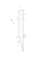
本実施形態に係る穿刺針100は、図1に示すように、棒状の本体部1と、本体部1の先端部に形成された針先部2と、本体部1の側部に形成された凹部3と、を備えている。なお、図1は、穿刺針100を側面から見た図である。 (Description of overview)
Thepuncture needle 100 according to the present embodiment, as shown in FIG. a recess 3; 1 is a side view of the puncture needle 100. FIG.
本実施形態に係る穿刺針100は、図1に示すように、棒状の本体部1と、本体部1の先端部に形成された針先部2と、本体部1の側部に形成された凹部3と、を備えている。なお、図1は、穿刺針100を側面から見た図である。 (Description of overview)
The
凹部3は、図2に示すように、本体部1の軸心Gに沿う方向から本体部1の径方向外側に0°以上75°以下反れた方向であって、基端側に壁面が向く先端側壁部31を有する。先端側壁部31における法線方向で見た場合に、先端側壁部31と、凹部3の基端側の本体部1(後述する境界部3a)とは離間している(図3参照)。なお、図2は、図1において、凹部3の近傍を拡大して示した一部拡大図である。図3は、凹部3を先端側壁部31における法線方向で見た場合、すなわち、図2におけるA矢視で凹部3を見た図である。
As shown in FIG. 2, the concave portion 3 is in a direction that deviates from the direction along the axis G of the body portion 1 to the radial direction outside of the body portion 1 by 0° or more and 75° or less, and the wall surface faces toward the base end side. It has a tip side wall portion 31 . When viewed in the direction normal to the tip side wall portion 31, the tip side wall portion 31 and the body portion 1 (boundary portion 3a described later) on the base end side of the recess 3 are separated from each other (see FIG. 3). 2 is a partially enlarged view showing the vicinity of the concave portion 3 in FIG. 1. As shown in FIG. FIG. 3 is a view of the concave portion 3 when viewed in the direction normal to the tip side wall portion 31, that is, when the concave portion 3 is viewed in the direction of arrow A in FIG.
穿刺針100は、図4に示すように、超音波診断装置のプローブ9を穿刺針100の基端側から穿刺針100における本体部1の軸心Gに沿う方向に向けて生体の体表面Hに当接させた状態での手技に適したものである。穿刺針100は、当該手技を行うに際し、後述するように、エコー視認性が向上している。
As shown in FIG. 4, the puncture needle 100 is directed from the base end side of the puncture needle 100 toward the axis G of the main body 1 of the puncture needle 100 toward the body surface H of the living body. It is suitable for procedures in a state in which it is in contact with the The puncture needle 100 has improved echo visibility when performing the procedure, as will be described later.
(各部の説明)
以下、穿刺針100の各部について説明する。 (Description of each part)
Each part of thepuncture needle 100 will be described below.
以下、穿刺針100の各部について説明する。 (Description of each part)
Each part of the
図1に示すように、本体部1は、棒状の一例として円柱状の筒状である。本体部1の筒内部の内壁10で区画された空間は内腔Sである。
As shown in FIG. 1, the main body 1 has a cylindrical cylindrical shape as an example of a rod shape. A space defined by an inner wall 10 inside the cylinder of the main body 1 is a lumen S. As shown in FIG.
本体部1は、例えばステンレスやチタン、チタン合金、コバルト-クロム合金などの金属又は金属合金やフッ素樹脂、ポリオレフィン樹脂などの合成樹脂で形成するとよい。本実施形態において、本体部1はステンレスで形成されている場合を例示している。
The main body 1 may be made of metal such as stainless steel, titanium, titanium alloy, cobalt-chromium alloy, or metal alloy, or synthetic resin such as fluororesin or polyolefin resin. In this embodiment, the main body 1 is made of stainless steel.
針先部2は、本体部1の先端に形成されている。針先部2は、例えば、軸心Gに沿う方向に対して本体部1の先端部を斜めに切断した刃面20を有する形状とされている。針先部2は、このような本体部1の先端部を斜めに切断した刃面20を有する形状以外の形状であってもよい。
The needlepoint portion 2 is formed at the tip of the body portion 1 . The tip portion 2 has a blade surface 20 obtained by cutting the tip portion of the body portion 1 obliquely with respect to the direction along the axis G, for example. The needle tip portion 2 may have a shape other than the shape having the blade surface 20 obtained by obliquely cutting the tip portion of the body portion 1 .
内腔Sは、本体部1の内部に、軸心Gに沿い連続的に形成された空間である。本実施形態において、内腔Sは、その軸心が軸心Gと重複し、軸心Gに直交する断面の形状が円形状の円柱形状の空間として形成されている。本実施形態において内腔Sは、刃面20に形成された開口部20sを介して外部空間と連通している場合を例示している。
The lumen S is a space continuously formed along the axis G inside the main body 1 . In this embodiment, the lumen S is formed as a columnar space whose axis overlaps with the axis G and whose cross section perpendicular to the axis G has a circular shape. In this embodiment, the lumen S communicates with the external space through an opening 20s formed in the blade surface 20. As shown in FIG.
凹部3は、本体部1の側部に形成されている。凹部3は、軸心Gと交差する方向に凹んでいる。凹部3は、穿刺針100の側面視において、本体部1の径方向外側が軸心Gに沿う方向において広くなる台形状、V字形状などに形成されてよい。図1、図2では、凹部3が台形状に形成されている場合を例示している。本実施形態において、凹部3は、図5に示すように、本体部1の外周面から内腔Sに達する範囲に形成されており、凹部3には、内腔Sと連通する開口部39が形成されている。すなわち凹部3は、内腔Sまで貫通している。なお、図5は、穿刺針100における凹部3の近傍の上面図であり、図1、図2に示した状態の穿刺針100を、図1の下から上に見る視点で見た図である。
The concave portion 3 is formed on the side portion of the main body portion 1 . The recess 3 is recessed in a direction intersecting with the axis G. The concave portion 3 may be formed in a trapezoidal shape, a V shape, or the like in which the radially outer side of the main body portion 1 becomes wider in the direction along the axis G when the puncture needle 100 is viewed from the side. 1 and 2 illustrate the case where the concave portion 3 is formed in a trapezoidal shape. In the present embodiment, as shown in FIG. 5, the recess 3 is formed in a range extending from the outer peripheral surface of the main body 1 to the lumen S, and the recess 3 has an opening 39 that communicates with the lumen S. formed. That is, the recess 3 penetrates to the lumen S. 5 is a top view of the vicinity of the recess 3 in the puncture needle 100, and is a view of the puncture needle 100 in the state shown in FIGS. 1 and 2, viewed from the bottom up in FIG. .
図1、図2及び図5に示すように、本実施形態において、凹部3は、針先部2に形成されている。すなわち、凹部3は、軸心Gに沿う方向において、針先部2と同じ位置に配置されている。刃面20との関係で説明すると、凹部3は、軸心Gに沿う方向において、刃面20と同じ位置に配置されている。これにより、針先部2のエコー下での視認性が向上する。凹部3は、刃面20と、軸心Gに対して本体部1の反対側に形成されるとよい。
As shown in FIGS. 1, 2 and 5, the concave portion 3 is formed in the needle tip portion 2 in this embodiment. That is, the concave portion 3 is arranged at the same position as the needle tip portion 2 in the direction along the axis G. As shown in FIG. Explaining the relationship with the blade surface 20 , the recess 3 is arranged at the same position as the blade surface 20 in the direction along the axis G. This improves the visibility of the needle tip 2 under echo. The concave portion 3 is preferably formed on the opposite side of the body portion 1 with respect to the blade surface 20 and the axis G.
図2、図5などに示すように、凹部3は、底面となる底壁部32、底壁部32よりも先端側に位置し、本体部1の外周面から底壁部32まで延在する先端側壁部31、及び、底壁部32よりも基端側に位置し、本体部1の外周面から底壁部32まで延在する基端側壁部33を有する。
As shown in FIGS. 2, 5, etc., the recess 3 has a bottom wall portion 32 that serves as a bottom surface, is located on the tip side of the bottom wall portion 32, and extends from the outer peripheral surface of the main body portion 1 to the bottom wall portion 32. It has a distal side wall portion 31 and a proximal side wall portion 33 positioned closer to the proximal side than the bottom wall portion 32 and extending from the outer peripheral surface of the body portion 1 to the bottom wall portion 32 .
底壁部32は、軸心Gに沿う平面状の底面を有する。底壁部32には、内腔Sに連通する開口部39(図3参照)が形成されている。開口部39は、穿刺針100において、いわゆるバックアイとして用いてよい。
The bottom wall portion 32 has a planar bottom surface along the axis G. An opening 39 (see FIG. 3) communicating with the lumen S is formed in the bottom wall portion 32 . The opening 39 may be used as a so-called back eye in the puncture needle 100 .
先端側壁部31は、本体部1の外周面であって、凹部3の先端から底壁部32まで延在している平面状の壁部である。先端側壁部31の平面部分は、軸心Gに沿う方向における基端側を向く向きから本体部1における径方向外側にやや傾斜している。すなわち、先端側壁部31は、本体部1の基端側における真後ろとなる向きから、本体部1の径方向外側に反れた方向に向いている。
The tip side wall portion 31 is the outer peripheral surface of the main body portion 1 and is a planar wall portion extending from the tip end of the concave portion 3 to the bottom wall portion 32 . The planar portion of the tip side wall portion 31 is slightly inclined radially outward in the main body portion 1 from the direction facing the base end side in the direction along the axis G. As shown in FIG. That is, the tip side wall portion 31 faces in a direction that is bent radially outward of the main body portion 1 from the direction directly behind the base end side of the main body portion 1 .
基端側壁部33は、本体部1の外周面であって、凹部3の基端から底壁部32まで延在している平面状の壁部である。基端側壁部33の平面部分は、軸心Gに沿う方向における先端側を向く向きから本体部1における径方向外側にやや傾斜している。すなわち、基端側壁部33は、本体部1の先端側における真正面となる向きから、本体部1の径方向外側に反れた方向に向いている。
The base end side wall portion 33 is a planar wall portion that is the outer peripheral surface of the main body portion 1 and extends from the base end of the concave portion 3 to the bottom wall portion 32 . The planar portion of the base end side wall portion 33 is slightly inclined radially outward in the main body portion 1 from the direction facing the distal end side in the direction along the axis G. As shown in FIG. That is, the base end side wall portion 33 faces in a direction that is bent radially outward of the main body portion 1 from the straight front direction on the distal end side of the main body portion 1 .
図2では、軸心G(本体部1)に対する所定の周方向の位置から穿刺針100を見た場合の側面視(本実施形態では図2に示す状態の側面視、以下、所定の側面視と称する)において、先端側壁部31の壁面に沿う仮想的な線であって、軸心Gと交差する線を仮想線L1として示している。なお、本実施形態における所定の側面視とは、凹部3を側面から見る視点である。
2 shows a side view when the puncture needle 100 is viewed from a predetermined circumferential position with respect to the axis G (body portion 1) (in this embodiment, a side view of the state shown in FIG. 2; hereinafter, a predetermined side view). ), a virtual line along the wall surface of the tip side wall portion 31 and intersecting with the axis G is indicated as a virtual line L1. It should be noted that the predetermined side view in the present embodiment is a viewpoint of viewing the concave portion 3 from the side.
図2では、所定の側面視において、底壁部32の壁面に沿う仮想的な線であって、軸心G及び仮想線L1と同一平面上に位置する線を仮想線L2として示している。
In FIG. 2, in a given side view, an imaginary line along the wall surface of the bottom wall portion 32 and positioned on the same plane as the axis G and the imaginary line L1 is indicated as an imaginary line L2.
仮想線L1と重複する先端側壁部31の壁面の平面部分は、基端側の向き、すなわち真後ろとなる向きから、本体部1の径方向外側に反れた方向に向いている。これにより、先端側壁部31はプローブ9からの超音波W1を反射波W2として基端側へ反射可能となる。図2では、仮想線L1、すなわち先端側壁部31の法線に沿う仮想的な線を仮想線L3として示している。
The planar portion of the wall surface of the tip side wall portion 31 that overlaps with the virtual line L1 faces in a direction that is bent radially outward of the main body portion 1 from the base end side direction, that is, the directly rearward direction. As a result, the distal side wall portion 31 can reflect the ultrasonic wave W1 from the probe 9 to the proximal side as the reflected wave W2. In FIG. 2, a virtual line L1, that is, a virtual line along the normal to the tip side wall portion 31 is shown as a virtual line L3.
図2では、仮想線L1と軸心Gとが交差する角度を交差角γで示しており、交差角γは、15°以上90°以下である。すなわち先端側壁部31は、軸心Gと15°以上90°以下の角度で交差している。
In FIG. 2, the angle at which the imaginary line L1 and the axis G intersect is indicated by the intersection angle γ, and the intersection angle γ is 15° or more and 90° or less. That is, the tip side wall portion 31 intersects the axis G at an angle of 15° or more and 90° or less.
図2では、仮想線L1(先端側壁部31)の法線に沿う仮想線L3と軸心Gとが交差する角度を交差角αで示している。すなわち、仮想線L1の法線に沿う仮想線L3は、軸心Gと0°以上75°以下で交差している。換言すると、仮想線L1と重複する先端側壁部31は、基端側における真後ろ、且つ、軸心Gに沿う方向から本体部1の径方向外側に0°以上75°以下反れた方向に向いている。
In FIG. 2, the angle at which an imaginary line L3 along the normal line of the imaginary line L1 (tip side wall portion 31) intersects with the axis G is indicated by an intersection angle α. That is, the imaginary line L3 along the normal line of the imaginary line L1 intersects the axis G at 0° or more and 75° or less. In other words, the tip side wall portion 31 that overlaps with the imaginary line L1 is directly behind the base end side, and is directed in a direction that deviates from the direction along the axis G to the radially outer side of the main body portion 1 by 0° or more and 75° or less. there is
軸心Gと重複する平面上に位置する凹部3の基端であって、基端側壁部33と本体部1の外表面との境界部3aと、先端側壁部31の底側端部と、を結ぶ仮想線L4は、仮想線L1、すなわち先端側壁部31に対して鈍角(90°越180°未満)で交わるように形成されている。なお、先端側壁部31の底側端部とは、先端側壁部31と底壁部32との境界位置である。
a boundary portion 3a between the proximal side wall portion 33 and the outer surface of the main body portion 1, which is the base end of the recessed portion 3 located on a plane overlapping the axis G; is formed to intersect with the virtual line L1, that is, the tip side wall portion 31 at an obtuse angle (90° to less than 180°). The bottom end of the tip side wall portion 31 is the boundary position between the tip side wall portion 31 and the bottom wall portion 32 .
本実施形態では、先端側壁部31と底壁部32との境界部分が曲面状に形成されている場合を示しているが、このような場合は、図2に示すように、仮想線L2と仮想線L1との交差部P1と、境界部3aと、を結ぶ仮想的な線(本実施形態では仮想線L4と同じ)が先端側壁部31と底壁部32との境界部分と交差する位置P2を先端側壁部31と底壁部32との境界位置と定義する。
This embodiment shows the case where the boundary portion between the tip side wall portion 31 and the bottom wall portion 32 is formed into a curved surface. A position where an imaginary line (same as the imaginary line L4 in this embodiment) connecting the intersecting portion P1 with the imaginary line L1 and the boundary portion 3a intersects the boundary portion between the tip side wall portion 31 and the bottom wall portion 32 P2 is defined as the boundary position between the tip side wall portion 31 and the bottom wall portion 32 .
図2では、仮想線L4と仮想線L1とが交差する角度を交差角βで示している。すなわち、交差角βが鈍角(90°越180°未満)である。これにより、底壁部32及び基端側壁部33が、先端側壁部31への超音波W1(図4参照)の入射を妨げることを回避できる。また、底壁部32及び基端側壁部33が、反射波W2(図4参照)を遮蔽することを回避することができる。そして、これらにより、超音波診断装置のプローブ9(図4参照)を穿刺針100の基端側から穿刺針100の軸心Gに沿う方向に向けて当てた状態における穿刺針100のエコー視認性を向上させることができる。なお、交差角βは、120越170°未満であることが好ましい。交差角βがこのような範囲であれば、通常想定される手技でのエコー下においてプローブ9が穿刺針100の基端側から穿刺針100の軸心Gに沿う方向から多少ずれても穿刺針100のエコー視認性を向上させることができる。
In FIG. 2, the angle at which the virtual line L4 and the virtual line L1 intersect is indicated by the intersection angle β. That is, the crossing angle β is an obtuse angle (more than 90° and less than 180°). Accordingly, it is possible to prevent the bottom wall portion 32 and the proximal side wall portion 33 from blocking the incidence of the ultrasonic wave W1 (see FIG. 4) to the distal side wall portion 31 . In addition, it is possible to prevent the bottom wall portion 32 and the base end side wall portion 33 from shielding the reflected wave W2 (see FIG. 4). As a result, the echo visibility of the puncture needle 100 in a state in which the probe 9 (see FIG. 4) of the ultrasound diagnostic apparatus is applied from the base end side of the puncture needle 100 in the direction along the axis G of the puncture needle 100 can be improved. The crossing angle β is preferably more than 120 and less than 170°. If the crossing angle β is within such a range, even if the probe 9 deviates slightly from the proximal end side of the puncture needle 100 from the direction along the axis G of the puncture needle 100 under the echo of a normally assumed procedure, the puncture needle can be detected. 100 echo visibility can be improved.
また、先端側壁部31が平面状に形成されていることから、先端側壁部31へ入射した超音波W1は拡散することなく反射する。そのため、反射波W2は、基端側に向けて大きなエネルギーで反射される。これにより、超音波診断装置のプローブ9(図4参照)を穿刺針100の基端側から穿刺針100の軸心Gに沿う方向に向けて当てた状態における穿刺針100のエコー視認性を更に向上させることができる。なお、先端側壁部31は曲面状に形成されていてもよい。先端側壁部31を曲面状にすることで、複数の角度(様々な角度)で入射した超音波W1を反射することが可能である。
Further, since the tip side wall portion 31 is formed flat, the ultrasonic waves W1 incident on the tip side wall portion 31 are reflected without diffusing. Therefore, the reflected wave W2 is reflected toward the base end with a large amount of energy. As a result, the echo visibility of the puncture needle 100 in a state in which the probe 9 (see FIG. 4) of the ultrasonic diagnostic apparatus is applied from the base end side of the puncture needle 100 in the direction along the axis G of the puncture needle 100 is further improved. can be improved. Note that the tip side wall portion 31 may be formed in a curved shape. By making the tip side wall portion 31 curved, it is possible to reflect the ultrasonic wave W1 incident at a plurality of angles (various angles).
(変形例の説明)
上記実施形態では、凹部3が、本体部1の側面視において、本体部1の径方向外側が軸心Gに沿う方向において広くなる台形状であり、凹部3が内腔Sまで貫通している場合を例示して説明した。しかし、凹部3は台形状に限られない。また、凹部3は必ずしも内腔Sまで貫通している必要はない。 (Explanation of modification)
In the above-described embodiment, theconcave portion 3 has a trapezoidal shape in which the radially outer side of the main body portion 1 becomes wider in the direction along the axis G when viewed from the side of the main body portion 1, and the concave portion 3 penetrates to the bore S. A case has been illustrated and explained. However, the concave portion 3 is not limited to a trapezoidal shape. Also, the recess 3 does not necessarily have to penetrate to the lumen S.
上記実施形態では、凹部3が、本体部1の側面視において、本体部1の径方向外側が軸心Gに沿う方向において広くなる台形状であり、凹部3が内腔Sまで貫通している場合を例示して説明した。しかし、凹部3は台形状に限られない。また、凹部3は必ずしも内腔Sまで貫通している必要はない。 (Explanation of modification)
In the above-described embodiment, the
(変形例1)
図6には、凹部3が内腔Sまで貫通していない場合の凹部3の近傍を拡大して示している。このように、凹部3は、内腔Sまで貫通している必要はない。 (Modification 1)
FIG. 6 shows an enlarged view of the vicinity of therecess 3 when the recess 3 does not penetrate to the lumen S. As shown in FIG. Thus, the recess 3 does not have to penetrate to the lumen S.
図6には、凹部3が内腔Sまで貫通していない場合の凹部3の近傍を拡大して示している。このように、凹部3は、内腔Sまで貫通している必要はない。 (Modification 1)
FIG. 6 shows an enlarged view of the vicinity of the
(変形例2)
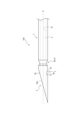
図7、図8には、凹部3が本体部1の側面視においてV字形状である場合を示している。凹部3は、平面状の先端側壁部31と平面状の基端側壁部33とで形成されている。図9には、この凹部3の近傍の上面図を示している。すなわち、図9は、図7、図8に示した状態の穿刺針100を、図1の下から上に見る視点で見た図である。 (Modification 2)
7 and 8 show the case where theconcave portion 3 is V-shaped in a side view of the main body portion 1. FIG. The concave portion 3 is formed by a planar tip side wall portion 31 and a planar base end side wall portion 33 . FIG. 9 shows a top view of the vicinity of the recess 3. As shown in FIG. That is, FIG. 9 is a view of the puncture needle 100 in the state shown in FIGS. 7 and 8, viewed from the bottom up in FIG.
図7、図8には、凹部3が本体部1の側面視においてV字形状である場合を示している。凹部3は、平面状の先端側壁部31と平面状の基端側壁部33とで形成されている。図9には、この凹部3の近傍の上面図を示している。すなわち、図9は、図7、図8に示した状態の穿刺針100を、図1の下から上に見る視点で見た図である。 (Modification 2)
7 and 8 show the case where the
このように凹部3が本体部1の側面視においてV字形状に形成される場合、上述の底壁部32(図2など参照)は基端側壁部33と面一となる。以下の説明では、底壁部32と基端側壁部33とが面一となる場合は、基端側壁部33が上述の底壁部32を包含するものとして扱い、また、説明を行う。例えば、上述の仮想線L2(図2参照)は、基端側壁部33に沿う線として取り扱う。
When the concave portion 3 is thus formed in a V shape when the main body portion 1 is viewed from the side, the bottom wall portion 32 (see FIG. 2 and the like) is flush with the base end side wall portion 33 . In the following description, when the bottom wall portion 32 and the base end side wall portion 33 are flush with each other, the base end side wall portion 33 is treated as including the bottom wall portion 32 described above, and the description will be made. For example, the virtual line L<b>2 (see FIG. 2 ) described above is treated as a line along the base end side wall portion 33 .
本変形例では、先端側壁部31の底側端部は、基端側壁部33の底側端部に繋がっている。換言すると、基端側壁部33は、先端側壁部31の底側端部から凹部3における基端に渡り延在する平面状の壁部として形成される。また、この場合、基端側壁部33は、基端側壁部33と本体部1の外表面との境界部3aと、先端側壁部31の底側端部と、を結ぶ仮想線L4と重複させるとよい。これにより、基端側壁部33が、先端側壁部31への超音波W1(図4参照)の入射を妨げることを回避できる。また、基端側壁部33が、反射波W2(図4参照)を遮蔽することを回避することができる。そして、これらにより、超音波診断装置のプローブ9(図4参照)を穿刺針100の基端側から穿刺針100の軸心Gに沿う方向に向けて当てた状態における穿刺針100のエコー視認性を向上させることができる。
In this modified example, the bottom side end of the distal side wall portion 31 is connected to the bottom side end of the proximal side wall portion 33 . In other words, the proximal side wall portion 33 is formed as a planar wall portion extending from the bottom side end of the distal side wall portion 31 to the proximal end of the recess 3 . Also, in this case, the base end side wall portion 33 overlaps an imaginary line L4 connecting the boundary portion 3a between the base end side wall portion 33 and the outer surface of the main body portion 1 and the bottom side end portion of the tip end side wall portion 31. Good. As a result, it is possible to prevent the proximal side wall portion 33 from blocking the incidence of the ultrasonic waves W1 (see FIG. 4) to the distal side wall portion 31 . In addition, it is possible to prevent the proximal side wall portion 33 from shielding the reflected wave W2 (see FIG. 4). As a result, the echo visibility of the puncture needle 100 in a state in which the probe 9 (see FIG. 4) of the ultrasound diagnostic apparatus is applied from the base end side of the puncture needle 100 in the direction along the axis G of the puncture needle 100 can be improved.
(変形例3)
図10に示すように、本体部1に複数の凹部3を形成してもよい。このようにすることで、超音波診断装置の超音波診断装置のプローブ9(図4参照)を穿刺針100の基端側から穿刺針100の軸心Gに沿う方向に向けて当てた状態における穿刺針100のエコー視認性を更に向上させることができる。 (Modification 3)
As shown in FIG. 10, a plurality ofrecesses 3 may be formed in the main body 1. As shown in FIG. By doing so, when the probe 9 (see FIG. 4) of the ultrasonic diagnostic apparatus of the ultrasonic diagnostic apparatus is applied from the base end side of the puncture needle 100 in the direction along the axis G of the puncture needle 100, The echo visibility of the puncture needle 100 can be further improved.
図10に示すように、本体部1に複数の凹部3を形成してもよい。このようにすることで、超音波診断装置の超音波診断装置のプローブ9(図4参照)を穿刺針100の基端側から穿刺針100の軸心Gに沿う方向に向けて当てた状態における穿刺針100のエコー視認性を更に向上させることができる。 (Modification 3)
As shown in FIG. 10, a plurality of
この場合、複数の凹部3の内、少なくとも一つは、軸心Gに沿う方向において、針先部2(図10では、刃面20)と同じ位置に配置するとよい。これにより、針先部2のエコー下での視認性が向上する。
In this case, at least one of the plurality of concave portions 3 should be arranged at the same position as the needle tip portion 2 (blade surface 20 in FIG. 10) in the direction along the axis G. This improves the visibility of the needle tip 2 under echo.
(変形例4)
図11に示すように、凹部3として、例えば本体部1の周方向に沿って環状に形成された凹部3Aを形成してもよい。凹部3Aは、本体部1に一つ以上形成してもよい。このようにすることで、超音波診断装置のプローブ9(図4参照)を穿刺針100の基端側から穿刺針100の軸心Gに沿う方向に向けて当てた状態において、穿刺針100がその周方向においてどのような向きであるかにかかわらず、穿刺針100のエコー視認性を向上させることができる。 (Modification 4)
As shown in FIG. 11, as therecess 3, for example, a recess 3A formed in an annular shape along the circumferential direction of the main body 1 may be formed. One or more concave portions 3A may be formed in the main body portion 1 . By doing so, in a state in which the probe 9 (see FIG. 4) of the ultrasonic diagnostic apparatus is applied from the base end side of the puncture needle 100 in the direction along the axis G of the puncture needle 100, the puncture needle 100 The echo visibility of the puncture needle 100 can be improved regardless of its orientation in the circumferential direction.
図11に示すように、凹部3として、例えば本体部1の周方向に沿って環状に形成された凹部3Aを形成してもよい。凹部3Aは、本体部1に一つ以上形成してもよい。このようにすることで、超音波診断装置のプローブ9(図4参照)を穿刺針100の基端側から穿刺針100の軸心Gに沿う方向に向けて当てた状態において、穿刺針100がその周方向においてどのような向きであるかにかかわらず、穿刺針100のエコー視認性を向上させることができる。 (Modification 4)
As shown in FIG. 11, as the
なお、図11に示す例では、穿刺針100が、軸心Gに沿う方向において先端側に配置された凹部3と、これよりも基端側に配置された凹部3Aとを有する場合を示している。先端側に配置された凹部3は、針先部2と同じ位置に配置されている。基端側に配置された凹部3Aは針先部2よりも基端側に配置されている。先端側の凹部3を側面から見る視点である上述の所定の側面視において、先端側の凹部3と基端側の凹部3である凹部3Aとは、相似形であってよい。図11に示す例では、先端側の凹部3と基端側の凹部3である凹部3Aとは、所定の側面視において同じ形状である。
Note that the example shown in FIG. 11 shows the case where the puncture needle 100 has the recess 3 arranged on the distal side in the direction along the axis G and the recess 3A arranged on the proximal side. there is The concave portion 3 arranged on the tip side is arranged at the same position as the needle tip portion 2 . The concave portion 3</b>A arranged on the proximal side is arranged on the proximal side of the needle tip portion 2 . In the above-described predetermined side view, which is a side view of the recessed portion 3 on the distal side, the recessed portion 3 on the distal side and the recessed portion 3A, which is the recessed portion 3 on the proximal side, may have similar shapes. In the example shown in FIG. 11, the recessed portion 3 on the distal end side and the recessed portion 3A, which is the recessed portion 3 on the proximal end side, have the same shape in a predetermined side view.
なお、図示しないが、本体部1の周方向に沿って凹部3を螺旋状に形成してもよい。この場合も、超音波診断装置のプローブ9(図4参照)を穿刺針100の基端側から穿刺針100の軸心Gに沿う方向に向けて当てた状態において、穿刺針100がその周方向においてどのような向きであるかにかかわらず、穿刺針100のエコー視認性を向上させることができる。
Although not shown, the concave portion 3 may be spirally formed along the circumferential direction of the main body portion 1 . In this case as well, when the probe 9 (see FIG. 4) of the ultrasonic diagnostic apparatus is applied from the base end side of the puncture needle 100 in the direction along the axis G of the puncture needle 100, the puncture needle 100 moves in the circumferential direction. The echo visibility of the puncture needle 100 can be improved regardless of the orientation in .
以上のようにして、超音波診断装置のプローブを穿刺針の基端側から穿刺針の軸心の方向に沿う方向に向けて当てた状態におけるエコー視認性を向上させた穿刺針を提供することができる。
As described above, there is provided a puncture needle with improved echo visibility in a state in which a probe of an ultrasonic diagnostic apparatus is applied from the base end side of the puncture needle in a direction along the axis of the puncture needle. can be done.
〔別実施形態〕
(1)上記実施形態では、本体部1が内腔Sを有する筒状である場合を例示して説明したが、本体部1は、中実の棒状であってもよい。 [Another embodiment]
(1) In the above-described embodiment, the case where themain body 1 has a cylindrical shape with the inner cavity S has been described as an example, but the main body 1 may have a solid rod shape.
(1)上記実施形態では、本体部1が内腔Sを有する筒状である場合を例示して説明したが、本体部1は、中実の棒状であってもよい。 [Another embodiment]
(1) In the above-described embodiment, the case where the
(2)上記実施形態では、針先部2が、軸心Gに沿う方向に対して本体部1の先端部を斜めに切断した刃面20を有する形状とされている場合を説明した。しかし、針先部2は、例えば、錐体状の形状とすることもできる。錐体状形状の一例は、円錐状や側面に複数の平面部を含む多角錘状の形状である。多角錘状の一例は、三角錐状、四角錘状及び五角以上の錘状の形状である。
(2) In the above embodiment, the needle tip portion 2 has a blade surface 20 formed by cutting the tip of the body portion 1 obliquely with respect to the direction along the axis G. However, the needle tip portion 2 can also have, for example, a conical shape. An example of the pyramidal shape is a conical shape or a polypyramidal shape including a plurality of plane portions on the side surface. Examples of the polygonal pyramid shape are a triangular pyramid shape, a square pyramid shape, and a pyramid shape with five or more angles.
なお、上記実施形態(別実施形態を含む、以下同じ)で開示される構成は、矛盾が生じない限り、他の実施形態で開示される構成と組み合わせて適用することが可能であり、また、本明細書において開示された実施形態は例示であって、本開示の実施形態はこれに限定されず、本開示の目的を逸脱しない範囲内で適宜改変することが可能である。
It should be noted that the configurations disclosed in the above embodiments (including other embodiments, the same shall apply hereinafter) can be applied in combination with configurations disclosed in other embodiments as long as there is no contradiction. The embodiments disclosed in this specification are exemplifications, and the embodiments of the present disclosure are not limited thereto, and can be modified as appropriate without departing from the scope of the present disclosure.
本開示は、穿刺針に適用できる。
The present disclosure can be applied to puncture needles.
1 :本体部
10 :内壁
100 :穿刺針
2 :針先部
20 :刃面
20s :開口部
3 :凹部
31 :先端側壁部
32 :底壁部
33 :基端側壁部
39 :開口部
3A :凹部
3a :境界部
9 :プローブ
G :軸心
H :体表面
L1 :仮想線
L2 :仮想線
L3 :仮想線
L4 :仮想線
P1 :交差部
P2 :位置
S :内腔
W1 :超音波
W2 :反射波
α :交差角
β :交差角
γ :交差角 Reference Signs List 1: Body 10: Inner wall 100: Puncture needle 2: Needle tip 20:Blade surface 20s: Opening 3: Recess 31: Distal side wall 32: Bottom wall 33: Base side wall 39: Opening 3A: Recess 3a : Boundary 9 : Probe G : Axis H : Body surface L1 : Virtual line L2 : Virtual line L3 : Virtual line L4 : Virtual line P1 : Intersection P2 : Position S : Lumen W1 : Ultrasonic wave W2 : Reflected wave α : Crossing angle β : Crossing angle γ : Crossing angle
10 :内壁
100 :穿刺針
2 :針先部
20 :刃面
20s :開口部
3 :凹部
31 :先端側壁部
32 :底壁部
33 :基端側壁部
39 :開口部
3A :凹部
3a :境界部
9 :プローブ
G :軸心
H :体表面
L1 :仮想線
L2 :仮想線
L3 :仮想線
L4 :仮想線
P1 :交差部
P2 :位置
S :内腔
W1 :超音波
W2 :反射波
α :交差角
β :交差角
γ :交差角 Reference Signs List 1: Body 10: Inner wall 100: Puncture needle 2: Needle tip 20:
Claims (6)
- 棒状の本体部と、
前記本体部の先端部に形成された針先部と
前記本体部の側部に形成された凹部と、を備え、
前記凹部は、前記本体部の軸心に沿う方向から前記本体部の径方向外側に0°以上75°以下反れた方向であって、基端側に壁面が向く先端側壁部を有し、
前記先端側壁部における法線方向で見た場合に、前記先端側壁部と、前記本体部とは離間している穿刺針。 a rod-shaped main body;
a needle tip formed at the tip of the main body and a recess formed at the side of the main body,
the concave portion has a tip side wall portion with a wall surface facing the base end side in a direction that deviates from the direction along the axis of the main body portion to the radially outer side of the main body portion by 0° or more and 75° or less;
A puncture needle in which the distal sidewall portion and the body portion are separated from each other when viewed in a normal direction of the distal sidewall portion. - 前記先端側壁部は、基端側における真後ろとなる向きから、本体部の径方向外側に反れた方向に向いている請求項1に記載の穿刺針。 The puncture needle according to claim 1, wherein the tip side wall portion faces in a direction that is bent radially outward of the main body portion from the directly rearward direction on the base end side.
- 前記先端側壁部の底側端部と、前記軸心に沿う方向における、前記凹部の基端と、を結ぶ仮想線が、前記先端側壁部に対して鈍角で交わる請求項1又は2に記載の穿刺針。 3. The imaginary line connecting the bottom end of the tip side wall and the base end of the recess in the direction along the axis intersects the tip side wall at an obtuse angle. puncture needle.
- 前記凹部は、平面状の前記先端側壁部と、前記先端側壁部の前記底側端部から前記凹部における前記基端に渡り延在する平面状の基端側壁部と、を有し、
前記基端側壁部は、前記仮想線に沿って形成されている請求項3に記載の穿刺針。 The recess has a planar distal sidewall and a planar proximal sidewall extending from the bottom end of the distal sidewall to the proximal end of the recess,
The puncture needle according to claim 3, wherein the proximal side wall portion is formed along the imaginary line. - 前記凹部は、前記針先部に形成されている請求項1から3の何れか一項に記載の穿刺針。 The puncture needle according to any one of claims 1 to 3, wherein the concave portion is formed in the needle tip portion.
- 前記針先部は、前記軸心に沿う方向に対して前記本体部の先端部を斜めに切断した刃面を有し、
前記凹部は、前記軸心に沿う方向において、前記刃面と同じ位置に配置されている請求項5に記載の穿刺針。 the needle tip portion has a blade surface obtained by obliquely cutting the tip portion of the main body portion with respect to the direction along the axis;
The puncture needle according to claim 5, wherein the recess is arranged at the same position as the blade surface in the direction along the axis.
Applications Claiming Priority (2)
| Application Number | Priority Date | Filing Date | Title |
|---|---|---|---|
| JP2022-003960 | 2022-01-13 | ||
| JP2022003960 | 2022-01-13 |
Publications (1)
| Publication Number | Publication Date |
|---|---|
| WO2023136303A1 true WO2023136303A1 (en) | 2023-07-20 |
Family
ID=87279165
Family Applications (1)
| Application Number | Title | Priority Date | Filing Date |
|---|---|---|---|
| PCT/JP2023/000658 WO2023136303A1 (en) | 2022-01-13 | 2023-01-12 | Puncture needle |
Country Status (1)
| Country | Link |
|---|---|
| WO (1) | WO2023136303A1 (en) |
Citations (9)
| Publication number | Priority date | Publication date | Assignee | Title |
|---|---|---|---|---|
| US5759154A (en) * | 1996-12-23 | 1998-06-02 | C. R. Bard, Inc. | Print mask technique for echogenic enhancement of a medical device |
| US6053870A (en) * | 1997-11-08 | 2000-04-25 | Angiodynamics, Inc. | Ultrasonic visible surgical needle |
| JP2001104314A (en) * | 1999-10-07 | 2001-04-17 | Asahi Optical Co Ltd | Tissue gathering device for endoscope |
| JP2010194013A (en) * | 2009-02-24 | 2010-09-09 | Hoya Corp | Puncture needle for ultrasonic endoscope |
| JP2011125632A (en) * | 2009-12-21 | 2011-06-30 | Terumo Corp | Ultrasonic guide puncture needle and indwelling needle |
| US20130267942A1 (en) * | 2012-03-16 | 2013-10-10 | Richard Eustis Fulton, III | Surgical Needle with Enhanced Ultrasound Reflectivity |
| JP2016516469A (en) * | 2013-03-14 | 2016-06-09 | マフィン・インコーポレイテッドMuffin Incorporated | Echogenic surface using Lulaw's triangle |
| JP2017000496A (en) * | 2015-06-11 | 2017-01-05 | 株式会社片岡製作所 | Needle processing method, laser beam processing machine, and needle |
| JP2017070775A (en) * | 2011-11-16 | 2017-04-13 | コヴィディエン リミテッド パートナーシップ | Needle biopsy device with exchangeable needle and integrated needle protection |
-
2023
- 2023-01-12 WO PCT/JP2023/000658 patent/WO2023136303A1/en unknown
Patent Citations (9)
| Publication number | Priority date | Publication date | Assignee | Title |
|---|---|---|---|---|
| US5759154A (en) * | 1996-12-23 | 1998-06-02 | C. R. Bard, Inc. | Print mask technique for echogenic enhancement of a medical device |
| US6053870A (en) * | 1997-11-08 | 2000-04-25 | Angiodynamics, Inc. | Ultrasonic visible surgical needle |
| JP2001104314A (en) * | 1999-10-07 | 2001-04-17 | Asahi Optical Co Ltd | Tissue gathering device for endoscope |
| JP2010194013A (en) * | 2009-02-24 | 2010-09-09 | Hoya Corp | Puncture needle for ultrasonic endoscope |
| JP2011125632A (en) * | 2009-12-21 | 2011-06-30 | Terumo Corp | Ultrasonic guide puncture needle and indwelling needle |
| JP2017070775A (en) * | 2011-11-16 | 2017-04-13 | コヴィディエン リミテッド パートナーシップ | Needle biopsy device with exchangeable needle and integrated needle protection |
| US20130267942A1 (en) * | 2012-03-16 | 2013-10-10 | Richard Eustis Fulton, III | Surgical Needle with Enhanced Ultrasound Reflectivity |
| JP2016516469A (en) * | 2013-03-14 | 2016-06-09 | マフィン・インコーポレイテッドMuffin Incorporated | Echogenic surface using Lulaw's triangle |
| JP2017000496A (en) * | 2015-06-11 | 2017-01-05 | 株式会社片岡製作所 | Needle processing method, laser beam processing machine, and needle |
Similar Documents
| Publication | Publication Date | Title |
|---|---|---|
| JP4700057B2 (en) | Puncture needle | |
| US8285097B2 (en) | Annular side fire optical device for laterally redirecting electromagnetic radiation | |
| US4977897A (en) | Amniocentesis needle with improved sonographic visibility | |
| US5048530A (en) | Method of using an amniocentesis needle with improved sonographic visibility | |
| JP3073994B2 (en) | Variable irradiation angle laser irradiation device | |
| US20040249288A1 (en) | Ultrasonic puncture needle | |
| US20220323153A1 (en) | Side-fire laser fiber having a molded reflective surface | |
| EP0414775A1 (en) | Echogenically enhanced surgical instrument and production method | |
| US4501278A (en) | Ultrasonic probe for puncture treatment | |
| CN107750152B (en) | Hollow needle for an ophthalmic surgical instrument | |
| WO2023136303A1 (en) | Puncture needle | |
| JP2010194013A (en) | Puncture needle for ultrasonic endoscope | |
| US10966750B2 (en) | Needle assembly with reverberation feature to facilitate ultrasound guidance of the needle assembly | |
| JP5190502B2 (en) | Ultrasound puncture needle | |
| WO2023136302A1 (en) | Puncture needle | |
| WO2023234011A1 (en) | Puncture needle | |
| CN219461329U (en) | Ultrasonic image guided puncture needle | |
| US11517667B2 (en) | Puncture needle | |
| CN217772505U (en) | Ultrasonic developing device | |
| CN220608378U (en) | Ultrasonic reflection structure and ultrasonic puncture needle | |
| US11278312B2 (en) | Introducer assembly with reverberation feature to facilitate ultrasound guidance | |
| CN210170134U (en) | Device for preparing ultrasonic guide puncture needle | |
| CN115715696A (en) | Puncture needle guided by ultrasonic image | |
| JP5253045B2 (en) | Eyeless needle | |
| CN111035450B (en) | Laser catheter |
Legal Events
| Date | Code | Title | Description |
|---|---|---|---|
| 121 | Ep: the epo has been informed by wipo that ep was designated in this application |
Ref document number: 23740311 Country of ref document: EP Kind code of ref document: A1 |