WO2023132132A1 - Image transmission system and image transmission device - Google Patents
Image transmission system and image transmission device Download PDFInfo
- Publication number
- WO2023132132A1 WO2023132132A1 PCT/JP2022/042547 JP2022042547W WO2023132132A1 WO 2023132132 A1 WO2023132132 A1 WO 2023132132A1 JP 2022042547 W JP2022042547 W JP 2022042547W WO 2023132132 A1 WO2023132132 A1 WO 2023132132A1
- Authority
- WO
- WIPO (PCT)
- Prior art keywords
- image
- performer
- seat
- line
- sight
- Prior art date
Links
Images


Classifications
-
- G—PHYSICS
- G06—COMPUTING; CALCULATING OR COUNTING
- G06T—IMAGE DATA PROCESSING OR GENERATION, IN GENERAL
- G06T7/00—Image analysis
-
- G—PHYSICS
- G06—COMPUTING; CALCULATING OR COUNTING
- G06T—IMAGE DATA PROCESSING OR GENERATION, IN GENERAL
- G06T7/00—Image analysis
- G06T7/70—Determining position or orientation of objects or cameras
-
- H—ELECTRICITY
- H04—ELECTRIC COMMUNICATION TECHNIQUE
- H04N—PICTORIAL COMMUNICATION, e.g. TELEVISION
- H04N21/00—Selective content distribution, e.g. interactive television or video on demand [VOD]
- H04N21/20—Servers specifically adapted for the distribution of content, e.g. VOD servers; Operations thereof
- H04N21/21—Server components or server architectures
- H04N21/218—Source of audio or video content, e.g. local disk arrays
- H04N21/2187—Live feed
-
- H—ELECTRICITY
- H04—ELECTRIC COMMUNICATION TECHNIQUE
- H04N—PICTORIAL COMMUNICATION, e.g. TELEVISION
- H04N21/00—Selective content distribution, e.g. interactive television or video on demand [VOD]
- H04N21/20—Servers specifically adapted for the distribution of content, e.g. VOD servers; Operations thereof
- H04N21/25—Management operations performed by the server for facilitating the content distribution or administrating data related to end-users or client devices, e.g. end-user or client device authentication, learning user preferences for recommending movies
- H04N21/258—Client or end-user data management, e.g. managing client capabilities, user preferences or demographics, processing of multiple end-users preferences to derive collaborative data
-
- H—ELECTRICITY
- H04—ELECTRIC COMMUNICATION TECHNIQUE
- H04N—PICTORIAL COMMUNICATION, e.g. TELEVISION
- H04N21/00—Selective content distribution, e.g. interactive television or video on demand [VOD]
- H04N21/20—Servers specifically adapted for the distribution of content, e.g. VOD servers; Operations thereof
- H04N21/25—Management operations performed by the server for facilitating the content distribution or administrating data related to end-users or client devices, e.g. end-user or client device authentication, learning user preferences for recommending movies
- H04N21/266—Channel or content management, e.g. generation and management of keys and entitlement messages in a conditional access system, merging a VOD unicast channel into a multicast channel
- H04N21/2665—Gathering content from different sources, e.g. Internet and satellite
Abstract
According to the present invention, a first imaging device captures a first image of a performer in a theater from the position of a virtual first seat that is set in the theater. A second imaging device captures a second image including the performer from a position different from the position of the first imaging device. A visual line detection unit detects the direction of the visual line of the performer. A transmission control unit transmits the second image to a terminal device of a viewer associated with the virtual first seat, and transmits the first image to the terminal device on the basis of the direction of the visual line of the performer having been pointed toward the virtual first seat.
Description
本発明は、画像送信システムおよび画像送信装置に関する。
The present invention relates to an image transmission system and an image transmission device.
従来、音楽、演劇、ダンス等の実演を映した画像(一般的には動画像)を、ネットワークを介してユーザの端末装置に送信する、いわゆるオンラインライブが広まっている。例えば、下記特許文献1には、ライブ映像配信システムが開示されている。映像データ処理装置は、入力された複数のカメラ映像を楽曲解析データまたは映像解析部が行った解析の結果に基づいて切り替えて出力する。また、複数のカメラ映像から特定の人物を検出し、楽曲中の音響の変化または映像の変化に応じて特定の人物がメインとなる映像に切り替えて映像を出力する。また、映像データ処理装置は、ユーザ端末から送信されたリクエストに応じた映像に切り替えて出力し、映像配信装置およびストリーミングサーバを介してユーザ端末に送信する。
Conventionally, so-called online live performances, in which images (generally moving images) showing performances of music, drama, dance, etc., are transmitted to users' terminal devices via networks, have become widespread. For example, Patent Literature 1 below discloses a live video distribution system. The image data processing device switches and outputs the input plural camera images based on the music analysis data or the result of the analysis performed by the image analysis unit. In addition, a specific person is detected from multiple camera images, and the specific person is switched to the main image according to changes in the sound or image in the music, and the image is output. Also, the video data processing device switches to a video according to a request transmitted from the user terminal, outputs the video, and transmits the video to the user terminal via the video distribution device and the streaming server.
オンラインライブは、視聴者が直接ライブ会場に来られない場合でも、実演の視聴が可能となるという面において高い利便性を有する。一方で、演者と視聴者との個別のやり取り、例えば演者と視聴者の目が合う、などの体験は、オンラインライブでは得ることができない。例えば、オンラインライブ中に演者が撮像装置に視線を向けたとしても、その画像はオンラインライブを視聴する視聴者全員が視聴可能である。よって、視聴者は、自身に対して演者が視線を向けたとは捉えない。このように、オンラインライブの視聴は、ライブ会場での実演の鑑賞と比較して、視聴者と演者との関係性が希薄になり、視聴者の満足度が低いという課題がある。
Online live performances are highly convenient in that even if viewers cannot come directly to the live venue, they will be able to watch the live performance. On the other hand, the experience of individual interaction between the performer and the audience, such as eye contact between the performer and the audience, cannot be obtained in online live performances. For example, even if a performer turns his or her line of sight to the imaging device during an online live performance, the image can be viewed by all viewers watching the online live performance. Therefore, the viewer does not perceive that the performer has turned his or her gaze. In this way, viewing online live performances has the problem that the relationship between viewers and performers is weaker than viewing live performances at live venues, and viewer satisfaction is low.
本発明の目的は、実演の映像を送信するに当たって、視聴者の満足度を向上させることにある。
The purpose of the present invention is to improve the viewer's satisfaction in transmitting the video of the demonstration.
本発明の一態様に係る画像送信システムは、現実空間内に設定された仮想的な第1座席の位置から、前記現実空間内の第1演者の第1画像を撮像する第1撮像装置と、前記第1撮像装置の前記位置と異なる位置から、前記演者を含む第2画像を撮像する第2撮像装置と、前記仮想的な第1座席に対応付けられた視聴者の端末装置に前記第2画像を送信する送信制御部と、前記演者の視線の向きを検出する検出部と、を備え、前記送信制御部は、前記演者の視線の向きが前記仮想的な第1座席に向いたことに基づいて、前記端末装置に前記第1画像を送信する。
An image transmission system according to an aspect of the present invention includes a first imaging device that captures a first image of a first performer in the physical space from a position of a virtual first seat set in the physical space; a second imaging device that captures a second image including the performer from a position different from the position of the first imaging device; a transmission control unit that transmits an image; and a detection unit that detects the line-of-sight direction of the performer, wherein the transmission control unit detects that the line-of-sight direction of the performer is directed toward the virtual first seat. Based on this, the first image is transmitted to the terminal device.
また、本発明の一態様に係る画像送信装置は、現実空間内に設定された仮想的な第1座席の位置から第1撮像装置によって撮像された、前記現実空間内の演者の第1画像を取得する第1取得部と、前記第1撮像装置と異なる位置から第2撮像装置によって撮像された、前記演者を含む第2画像を取得する第2取得部と、前記仮想的な第1座席に対応付けられた視聴者の端末装置に前記第2画像を送信する送信制御部と、前記演者の視線の向きを検出する検出部と、を備え、前記送信制御部は、前記演者の視線が前記仮想的な第1座席に向いたことに基づいて、前記端末装置に前記第1画像を送信する。
Further, the image transmission device according to one aspect of the present invention transmits the first image of the performer in the physical space captured by the first imaging device from the position of the virtual first seat set in the physical space. a first acquisition unit that acquires; a second acquisition unit that acquires a second image including the performer captured by a second imaging device from a position different from that of the first imaging device; A transmission control unit that transmits the second image to the associated terminal device of the viewer, and a detection unit that detects the line-of-sight direction of the performer. The first image is transmitted to the terminal device based on facing the first virtual seat.
本発明の一態様によれば、実演の映像を送信するに当たって、視聴者の満足度を向上させることができる。
According to one aspect of the present invention, it is possible to improve the viewer's satisfaction in transmitting the video of the demonstration.
A.第1実施形態
以下、本発明の第1実施形態に係る画像送信システム1の構成について説明する。 A. First Embodiment A configuration of an image transmission system 1 according to a first embodiment of the present invention will be described below.
以下、本発明の第1実施形態に係る画像送信システム1の構成について説明する。 A. First Embodiment A configuration of an image transmission system 1 according to a first embodiment of the present invention will be described below.
A-1.システム構成
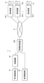
図1は、第1実施形態に係る画像送信システム1の構成を示すブロック図である。画像送信システム1は、第1撮像装置10と、移動機構50と、第2撮像装置20と、画像送信装置30Aとを備える。画像送信装置30Aは、通信網Nを介して複数の端末装置40-1~40-n(nは1以上の任意の整数)と接続されている。それぞれの端末装置40-1~40-nは、互いに異なる視聴者V1~Vnに保持されている。本実施形態では、後述する座席C1~C7(図2参照)に視聴者V1~V7が一対一で対応付けられている。視聴者V1~V7は、それぞれ端末装置40-1~40-7を保持する。よって、図1には、画像送信装置30Aに接続された端末装置40-1~40-nの一例として、端末装置40-1~40-7を図示している。すなわち、本実施形態は、n=7の場合について例示する。以下、端末装置40-1~40-7のうち任意の1台を表す場合には、端末装置40-i(i=1から7のうち任意の整数)と表記する。また、視聴者V1~V7のうち任意の1人を表す場合には、視聴者Vi(i=1から7のうち任意の整数)と表記する。 A-1. System Configuration FIG. 1 is a block diagram showing the configuration of an image transmission system 1 according to the first embodiment. The image transmission system 1 includes afirst imaging device 10, a moving mechanism 50, a second imaging device 20, and an image transmission device 30A. The image transmission device 30A is connected via a communication network N to a plurality of terminal devices 40-1 to 40-n (n is any integer equal to or greater than 1). The respective terminal devices 40-1 to 40-n are held by different viewers V1 to Vn. In this embodiment, viewers V1 to V7 are associated one-to-one with seats C1 to C7 (see FIG. 2), which will be described later. Viewers V1 to V7 hold terminal devices 40-1 to 40-7, respectively. Therefore, FIG. 1 shows terminal devices 40-1 to 40-7 as examples of terminal devices 40-1 to 40-n connected to the image transmitting device 30A. That is, this embodiment illustrates the case of n=7. Hereinafter, any one of the terminal devices 40-1 to 40-7 will be referred to as a terminal device 40-i (i=any integer from 1 to 7). When an arbitrary one of the viewers V1 to V7 is represented, the viewer is expressed as a viewer Vi (i=an arbitrary integer from 1 to 7).
図1は、第1実施形態に係る画像送信システム1の構成を示すブロック図である。画像送信システム1は、第1撮像装置10と、移動機構50と、第2撮像装置20と、画像送信装置30Aとを備える。画像送信装置30Aは、通信網Nを介して複数の端末装置40-1~40-n(nは1以上の任意の整数)と接続されている。それぞれの端末装置40-1~40-nは、互いに異なる視聴者V1~Vnに保持されている。本実施形態では、後述する座席C1~C7(図2参照)に視聴者V1~V7が一対一で対応付けられている。視聴者V1~V7は、それぞれ端末装置40-1~40-7を保持する。よって、図1には、画像送信装置30Aに接続された端末装置40-1~40-nの一例として、端末装置40-1~40-7を図示している。すなわち、本実施形態は、n=7の場合について例示する。以下、端末装置40-1~40-7のうち任意の1台を表す場合には、端末装置40-i(i=1から7のうち任意の整数)と表記する。また、視聴者V1~V7のうち任意の1人を表す場合には、視聴者Vi(i=1から7のうち任意の整数)と表記する。 A-1. System Configuration FIG. 1 is a block diagram showing the configuration of an image transmission system 1 according to the first embodiment. The image transmission system 1 includes a
画像送信システム1は、第1撮像装置10および第2撮像装置20が撮像した画像(後述する第1画像PC1および第2画像PC2)を、端末装置40-1~40-7に送信するためのシステムである。より詳細には、第1撮像装置10および第2撮像装置20は、歌唱等の実演を行っている演者P(図2参照)を撮像する。視聴者Viは、端末装置40-iを用いて、実演を行っている演者Pが映る画像を視聴する。すなわち、画像送信システム1は、オンラインライブの送信に用いられる。
The image transmission system 1 is for transmitting images captured by the first imaging device 10 and the second imaging device 20 (first image PC1 and second image PC2 described later) to the terminal devices 40-1 to 40-7. System. More specifically, the first imaging device 10 and the second imaging device 20 capture an image of a performer P (see FIG. 2) who is performing a performance such as singing. A viewer Vi uses a terminal device 40-i to view an image showing a performer P performing a performance. That is, the image transmission system 1 is used for online live transmission.
本実施形態では、オンラインライブは、実演の画像をリアルタイムに送信する、いわゆる生配信である場合について検討する。これに限らず、オンラインライブは、予め収録された実演の画像を事後的に送信する方式であってもよい。
In this embodiment, the online live is a so-called live distribution in which images of the performance are transmitted in real time. The online live is not limited to this, and may be a system in which pre-recorded images of the demonstration are transmitted after the fact.
端末装置40-iは、例えばスマートフォン、タブレット端末、パーソナルコンピュータ、スマートグラス、またはVRグラス等の情報処理装置である。端末装置40-iは、例えばディスプレイ等の画像表示装置と、スピーカと、通信網Nに接続する通信装置とを備える。
The terminal device 40-i is an information processing device such as a smart phone, tablet terminal, personal computer, smart glasses, or VR glasses. The terminal device 40-i includes an image display device such as a display, a speaker, and a communication device connected to the communication network N, for example.
第1撮像装置10は、撮像光学系および撮像素子を有する。撮像光学系は、少なくとも1つの撮像レンズを含む光学系である。例えば、撮像光学系は、プリズム等の各種の光学素子を有してもよいし、ズームレンズまたはフォーカスレンズ等を有してもよい。撮像素子は、例えば、CCD(Charge Coupled Device)イメージセンサーまたはCMOS(Complementary MOS)イメージセンサー等である。
The first imaging device 10 has an imaging optical system and an imaging element. An imaging optical system is an optical system that includes at least one imaging lens. For example, the imaging optical system may have various optical elements such as a prism, or may have a zoom lens, a focus lens, or the like. The imaging device is, for example, a CCD (Charge Coupled Device) image sensor or a CMOS (Complementary MOS) image sensor.
また、第1撮像装置10は、画像送信装置30Aに画像データを出力するためのインターフェースを備える。第1撮像装置10と画像送信装置30Aとは、有線で接続されていてもよいし、無線で接続されていてもよい。第2撮像装置20も、第1撮像装置10と同様の構成を有する。第1撮像装置10および第2撮像装置20は、一例では、ビデオカメラである
The first imaging device 10 also includes an interface for outputting image data to the image transmission device 30A. The first imaging device 10 and the image transmission device 30A may be connected by wire or may be connected by radio. The second imaging device 20 also has the same configuration as the first imaging device 10 . The first imaging device 10 and the second imaging device 20 are, for example, video cameras.
第1撮像装置10によって撮像された画像を第1画像PC1と呼び、第1画像PC1に対応する画像データを第1画像データと呼ぶ。また、第2撮像装置20によって撮像された画像を第2画像PC2と呼び、第2画像PC2に対応する画像データを第2画像データと呼ぶ。本実施形態では、第1撮像装置10および第2撮像装置20は、動画像を撮像する。第1撮像装置10は、所定のフレームレートで画像を撮像し、第1画像PC1に対応する第1画像データを生成し、生成された第1画像データを画像送信装置30Aに出力する。第2撮像装置20も同様に、第2画像PC2に対応する第2画像データを生成し、生成された第2画像データを画像送信装置30Aに出力する。
An image captured by the first imaging device 10 is called a first image PC1, and image data corresponding to the first image PC1 is called first image data. An image captured by the second imaging device 20 is called a second image PC2, and image data corresponding to the second image PC2 is called second image data. In this embodiment, the first imaging device 10 and the second imaging device 20 capture moving images. The first imaging device 10 captures an image at a predetermined frame rate, generates first image data corresponding to the first image PC1, and outputs the generated first image data to the image transmission device 30A. The second imaging device 20 similarly generates second image data corresponding to the second image PC2, and outputs the generated second image data to the image transmission device 30A.
図2は、第1撮像装置10および第2撮像装置20の配置を模式的に示す説明図である。図2は、劇場Gを上方から見た図である。劇場G内の空間は現実空間の一例である。第1撮像装置10および第2撮像装置20は、劇場G内の演者Pを撮像する。本実施形態では、演者Pは、劇場G内に設置された舞台S上で歌唱等のライブパフォーマンスを行う。実演は、歌唱に限らず、例えば芝居またはダンスなどであってもよい。本実施形態では、劇場G内の空間は、比較的小規模であり、演者Pの視線の向きLは各座席C1~C7から識別され得る。
FIG. 2 is an explanatory diagram schematically showing the arrangement of the first imaging device 10 and the second imaging device 20. As shown in FIG. FIG. 2 is a diagram of Theater G viewed from above. The space inside the theater G is an example of the real space. The first imaging device 10 and the second imaging device 20 capture an image of the performer P in the theater G. In this embodiment, the performer P performs a live performance such as singing on the stage S installed in the theater G. The performance is not limited to singing, and may be, for example, acting or dancing. In this embodiment, the space within the theater G is relatively small, and the gaze direction L of the performer P can be identified from each seat C1-C7.
劇場G内には、仮想的な複数の座席C1~C7が配置されている。例えば座席C1を第1座席、座席C2を第2座席とすると、劇場G内には、座席C1の物理的な位置と異なる物理的な位置に座席C2が配置されている。以下、座席C1~C7のうち任意の1席を表す場合には、座席Ci(i=1から7のうち任意の整数)と表記する。座席C1~C7は、例えば劇場Gの床を複数の区画に分割して各区画に対して識別情報(席番)を付したものである。なお、座席C1~C7は、劇場Gに実際に設置されている椅子であってもよい。各座席C1~C7には、それぞれ視聴者V1~V7が対応付けられている。例えば、座席C1には視聴者V1が対応付けられている。すなわち、座席Ciには、視聴者Viが対応付けられている。視聴者Viが保持する端末装置40-iを、座席Ciに対応付けられた端末装置40-iと表記する場合がある。
A plurality of virtual seats C1 to C7 are arranged in Theater G. For example, assuming that the seat C1 is the first seat and the seat C2 is the second seat, the seat C2 is arranged in the theater G at a physical position different from the physical position of the seat C1. Hereinafter, when an arbitrary one of the seats C1 to C7 is represented, it is expressed as a seat Ci (i=an arbitrary integer from 1 to 7). The seats C1 to C7 are obtained by dividing the floor of the theater G into a plurality of sections and assigning identification information (seat number) to each section. Note that the seats C1 to C7 may be chairs actually installed in the theater G. Viewers V1 to V7 are associated with the respective seats C1 to C7. For example, seat C1 is associated with viewer V1. That is, the seat Ci is associated with the viewer Vi. The terminal device 40-i held by the viewer Vi may be referred to as the terminal device 40-i associated with the seat Ci.
視聴者Viは、オンラインライブの視聴を申し込みする時に(または申し込みの後、かつライブ開始の前に)座席Ciが割り当てられる。視聴者Viに対して、座席C1~C7のうちいずれが割り当てられるかは、視聴者Viが自身で決定できてもよいし、抽選等で決定されてもよい。オンラインライブの視聴に料金の支払いが必要な場合、座席C1~C7の位置に応じて料金が変動してもよい。例えば、舞台Sの中央に近い座席Ciほど料金が高くなる、などとされてもよい。また、1つの座席Ciには、複数の視聴者Vi-1,Vi-2・・・が対応付けられてもよい。一方で、本実施形態では、オンラインライブを視聴する視聴者V1~Vj(jは任意の整数)の全員が同じ座席Ciに割り当てられることはない。視聴者V1~Vjの全員が同じ座席Ciに割り当てられると、視聴者V1~Vjの全員が同じ画像を視聴することになり、実質的には座席Ciの割り当てがなされていないに等しいためである。
Viewers Vi are assigned seats Ci when they apply to watch online live (or after applying and before the start of the live). Which of the seats C1 to C7 is assigned to the viewer Vi may be determined by the viewer Vi himself or may be determined by lottery or the like. If a charge is required for viewing the online live, the charge may vary according to the positions of the seats C1 to C7. For example, the closer the seat Ci is to the center of the stage S, the higher the fare may be. A plurality of viewers Vi-1, Vi-2, . . . may be associated with one seat Ci. On the other hand, in this embodiment, all the viewers V1 to Vj (j is an arbitrary integer) watching the online live are not assigned to the same seat Ci. This is because if all the viewers V1 to Vj are assigned to the same seat Ci, all the viewers V1 to Vj view the same image, which is substantially equivalent to no seat Ci being assigned. .
第1撮像装置10は、劇場G内に仮想的に配置された座席Ciの位置から、劇場G内で実演を行う演者Pの第1画像PC1を撮像する。第1実施形態では、第1撮像装置10は、座席C1~C7の間を移動可能である。第1撮像装置10は、座席C1~C7のいずれかの位置から演者Pの画像を第1画像PC1として撮像する。例えば、第1撮像装置10が座席C1の位置にあるときには、座席C1の位置から演者Pの画像が、第1画像PC1として撮像される。また、第1撮像装置10が座席C2の位置にあるときには、座席C2の位置から演者Pの画像が、第1画像PC1として撮像される。
The first imaging device 10 captures a first image PC1 of the performer P performing the performance in the theater G from the position of the seat Ci virtually arranged in the theater G. In the first embodiment, the first imaging device 10 is movable between the seats C1 to C7. The first imaging device 10 captures an image of the performer P as a first image PC1 from any position on the seats C1 to C7. For example, when the first imaging device 10 is located at the seat C1, an image of the performer P is captured as the first image PC1 from the position of the seat C1. Also, when the first imaging device 10 is located at the seat C2, an image of the performer P is captured as the first image PC1 from the position of the seat C2.
第1撮像装置10は、移動機構50に搭載されている。移動機構50は、座席C1~C7の間で第1撮像装置10を移動させる。移動機構50は、後述する移動制御部314の制御に基づいて第1撮像装置10を移動させる。移動機構50は、レール52と、本体54と、アーム56とを有する。レール52は、座席C1~C7の配列に沿って設置されている。本体54は、レール52上を移動する駆動輪と、駆動輪を回転させるアクチュエータ等を収容する。アーム56は、一端が本体54に固定され、他端が第1撮像装置10に固定されている。本体54がレール52上を移動することによって、第1撮像装置10は、劇場G内を左右に移動する。アーム56は、図示しないアクチュエータに接続されており、上下に伸縮可能である。よって、第1撮像装置10は、劇場G内に上下にも移動可能である。
The first imaging device 10 is mounted on the moving mechanism 50 . The moving mechanism 50 moves the first imaging device 10 among the seats C1 to C7. The movement mechanism 50 moves the first imaging device 10 based on the control of the movement control section 314, which will be described later. The moving mechanism 50 has a rail 52 , a main body 54 and an arm 56 . Rails 52 are installed along the arrangement of seats C1 to C7. The main body 54 accommodates the drive wheels that move on the rails 52, actuators that rotate the drive wheels, and the like. The arm 56 has one end fixed to the main body 54 and the other end fixed to the first imaging device 10 . As the main body 54 moves on the rails 52, the first imaging device 10 moves left and right in the theater G. As shown in FIG. The arm 56 is connected to an actuator (not shown) and can extend and contract vertically. Therefore, the first imaging device 10 can move up and down in the theater G as well.
なお、移動機構50を用いて第1撮像装置10を移動させるのではなく、撮像担当者が第1撮像装置10を移動させてもよい。
Instead of moving the first imaging device 10 using the moving mechanism 50, the person in charge of imaging may move the first imaging device 10.
図3Aおよび図3Bは、第1画像PC1を模式的に示す説明図である。本実施形態では、第1撮像装置10の撮像倍率は、主に演者Pの顔が画像を大きく占めるように設定される。第1画像PC1を視聴することによって、視聴者Viは、演者Pの表情および視線の向きL(図2参照)などを把握できる。
3A and 3B are explanatory diagrams schematically showing the first image PC1. In this embodiment, the imaging magnification of the first imaging device 10 is set so that the face of the performer P mainly occupies a large part of the image. By viewing the first image PC1, the viewer Vi can grasp the facial expression of the performer P, the line-of-sight direction L (see FIG. 2), and the like.
図3Aは、図2に示すように演者Pの視線の向きLが座席C4に向いている場合に、座席C4の位置から撮像した第1画像PC1-Aを示す。第1画像PC1-Aでは、演者Pが第1撮像装置10(座席C4)を向いているため、第1画像PC1-Aを視聴する視聴者Viは、演者Pが自身を向いているように見える。
FIG. 3A shows the first image PC1-A captured from the position of the seat C4 when the line-of-sight direction L of the performer P faces the seat C4 as shown in FIG. In the first image PC1-A, the performer P faces the first imaging device 10 (seat C4). appear.
一方、図3Bは、図2に示すように演者Pの視線の向きLが座席C4に向いている場合に、座席C1の位置から撮像した第1画像PC1-Bを示す。第1画像PC1-Bは、演者Pが第1撮像装置10を向いていないため、第1画像PC1-Bを視聴する視聴者Viは、演者Pが自身を向いているようには見えない。
On the other hand, FIG. 3B shows the first image PC1-B captured from the position of the seat C1 when the line-of-sight direction L of the performer P faces the seat C4 as shown in FIG. In the first image PC1-B, since the performer P is not facing the first imaging device 10, the viewer Vi viewing the first image PC1-B does not see the performer P facing himself.
第2撮像装置20は、第1撮像装置10と異なる位置から、演者Pを含む第2画像PC2を撮像する。本実施形態では、第2撮像装置20は、第1撮像装置10よりも舞台Sから離れた位置から、舞台S全体を撮像する。第2撮像装置20は、位置が固定されていてもよいし、第1撮像装置10と同様に移動機構50に搭載され劇場G内を移動可能であってもよい。また、劇場G内に、第2撮像装置20に対応する撮像装置が複数設置されていてもよい。例えば、図2に示すように舞台Sを正面から撮像する撮像装置の他、舞台Sを右側から撮像する撮像装置および舞台Sを左側から撮像する撮像装置が、第2撮像装置20として設置されていてもよい。
The second imaging device 20 captures a second image PC2 including the performer P from a position different from that of the first imaging device 10 . In this embodiment, the second imaging device 20 images the entire stage S from a position farther from the stage S than the first imaging device 10 . The position of the second imaging device 20 may be fixed, or, like the first imaging device 10, it may be mounted on the moving mechanism 50 and movable within the theater G. FIG. Also, in the theater G, a plurality of imaging devices corresponding to the second imaging device 20 may be installed. For example, as shown in FIG. 2, in addition to an imaging device that images the stage S from the front, an imaging device that images the stage S from the right side and an imaging device that images the stage S from the left side are installed as the second imaging devices 20. may
図4は、第2画像PC2を模式的に示す説明図である。図4に示す第2画像PC2には、舞台Sの広範囲と、演者Pの全身とが映っている。第2画像PC2を視聴することによって、視聴者Viは、演者Pの身体の動き、および、舞台S上の演出などを把握できる。
FIG. 4 is an explanatory diagram schematically showing the second image PC2. A wide range of the stage S and the whole body of the performer P are shown in the second image PC2 shown in FIG. By viewing the second image PC2, the viewer Vi can grasp the body movements of the performer P, the production on the stage S, and the like.
図3A、図3Bおよび図4に示すように、第1画像PC1に占める演者Pの割合は、第2画像PC2に占める演者Pの割合より大きい。言い換えると、第1画像PC1の撮像倍率は第2画像PC2の撮像倍率より大きい。
As shown in FIGS. 3A, 3B, and 4, the proportion of the actor P in the first image PC1 is greater than the proportion of the actor P in the second image PC2. In other words, the imaging magnification of the first image PC1 is greater than the imaging magnification of the second image PC2.
A-2.画像送信装置30A
図5は、画像送信装置30Aの構成を示すブロック図である。画像送信装置30Aは、例えばコンピュータであり、端末装置40-1~40-7に対して、第1画像PC1および第2画像PC2を送信する。画像送信装置30Aは、入力装置301と、表示装置302と、通信装置303と、画像入力インターフェース(I/F)304と、記憶装置305と、処理装置306Aと、バス307とを含む。入力装置301と、表示装置302と、通信装置303と、画像入力インターフェース304と、記憶装置305と、処理装置306Aとは、情報を通信するためのバス307によって相互に接続される。バス307は、単一のバスを用いて構成されてもよいし、装置間ごとに異なるバスを用いて構成されてもよい。 A-2.Image transmission device 30A
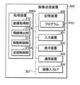
FIG. 5 is a block diagram showing the configuration of theimage transmission device 30A. The image transmission device 30A is, for example, a computer, and transmits the first image PC1 and the second image PC2 to the terminal devices 40-1 to 40-7. The image transmission device 30A includes an input device 301, a display device 302, a communication device 303, an image input interface (I/F) 304, a storage device 305, a processing device 306A, and a bus 307. The input device 301, the display device 302, the communication device 303, the image input interface 304, the storage device 305, and the processing device 306A are interconnected by a bus 307 for communicating information. The bus 307 may be configured using a single bus, or may be configured using different buses between devices.
図5は、画像送信装置30Aの構成を示すブロック図である。画像送信装置30Aは、例えばコンピュータであり、端末装置40-1~40-7に対して、第1画像PC1および第2画像PC2を送信する。画像送信装置30Aは、入力装置301と、表示装置302と、通信装置303と、画像入力インターフェース(I/F)304と、記憶装置305と、処理装置306Aと、バス307とを含む。入力装置301と、表示装置302と、通信装置303と、画像入力インターフェース304と、記憶装置305と、処理装置306Aとは、情報を通信するためのバス307によって相互に接続される。バス307は、単一のバスを用いて構成されてもよいし、装置間ごとに異なるバスを用いて構成されてもよい。 A-2.
FIG. 5 is a block diagram showing the configuration of the
入力装置301は、画像送信装置30Aの管理者からの操作を受け付ける機器である。例えば、入力装置301は、キーボード、タッチパッド、タッチパネルまたはマウス等のポインティングデバイスを含んで構成される。入力装置301がタッチパネルを含んで構成される場合、入力装置301は表示装置302を兼ねてもよい。
The input device 301 is a device that receives operations from the administrator of the image transmission device 30A. For example, the input device 301 includes a pointing device such as a keyboard, touch pad, touch panel, or mouse. When the input device 301 includes a touch panel, the input device 301 may also serve as the display device 302 .
表示装置302は、画像および文字情報を表示するデバイスである。表示装置302は、処理装置306Aの制御のもとで各種の画像を表示する。例えば、液晶表示パネルおよび有機EL表示パネル等の各種の表示パネルが表示装置302として好適に利用される。
The display device 302 is a device that displays images and character information. The display device 302 displays various images under the control of the processing device 306A. For example, various display panels such as a liquid crystal display panel and an organic EL display panel are preferably used as the display device 302 .
通信装置303は、無線通信または有線通信を用いて端末装置40-1~40-7と通信する。本実施形態において、通信装置303は、通信網Nに接続可能なインターフェースを備え、通信網Nを介して端末装置40-1~40-7と通信する。
The communication device 303 communicates with the terminal devices 40-1 to 40-7 using wireless communication or wired communication. In this embodiment, the communication device 303 has an interface connectable to the communication network N, and communicates with the terminal devices 40-1 to 40-7 via the communication network N. FIG.
画像入力インターフェース304は、第1撮像装置10および第2撮像装置20との接続インターフェースである。画像入力インターフェース304を介して、第1画像データおよび第2画像データが画像送信装置30Aに入力される。
The image input interface 304 is a connection interface with the first imaging device 10 and the second imaging device 20 . Via the image input interface 304, the first image data and the second image data are input to the image transmission device 30A.
記憶装置305は、処理装置306Aが読み取り可能な記録媒体である。記憶装置305は、例えば、不揮発性メモリーと揮発性メモリーとを含む。不揮発性メモリーは、例えば、ROM(Read Only Memory)、EPROM(Erasable Programmable Read Only Memory)およびEEPROM(Electrically Erasable Programmable Read Only Memory)である。揮発性メモリーは、例えば、RAM(Random Access Memory)である。記憶装置305は、プログラムPG1を記憶する。プログラムPG1は、画像送信装置30Aを動作させるためのプログラムである。
The storage device 305 is a recording medium readable by the processing device 306A. Storage device 305 includes, for example, non-volatile memory and volatile memory. Non-volatile memories are, for example, ROM (Read Only Memory), EPROM (Erasable Programmable Read Only Memory) and EEPROM (Electrically Erasable Programmable Read Only Memory). Volatile memory is, for example, RAM (Random Access Memory). Storage device 305 stores program PG1. The program PG1 is a program for operating the image transmission device 30A.
処理装置306Aは、1または複数のCPU(Central Processing Unit)を含む。1または複数のCPUは、1または複数のプロセッサの一例である。プロセッサおよびCPUの各々は、コンピュータの一例である。
The processing device 306A includes one or more CPUs (Central Processing Units). One or more CPUs is an example of one or more processors. Each of the processor and CPU is an example of a computer.
処理装置306Aは、記憶装置305からプログラムPG1を読み取る。処理装置306Aは、プログラムPG1を実行することによって、画像取得部310、視線検出部312A、移動制御部314、および送信制御部316Aとして機能する。画像取得部310、視線検出部312A、移動制御部314、および送信制御部316Aのうち少なくとも1つは、DSP(Digital Signal Processor)、ASIC(Application Specific Integrated Circuit)、PLD(Programmable Logic Device)およびFPGA(Field Programmable Gate Array)等の回路によって構成されてもよい。
The processing device 306A reads the program PG1 from the storage device 305. The processing device 306A functions as an image acquisition unit 310, a line-of-sight detection unit 312A, a movement control unit 314, and a transmission control unit 316A by executing the program PG1. At least one of the image acquisition unit 310, line-of-sight detection unit 312A, movement control unit 314, and transmission control unit 316A includes a DSP (Digital Signal Processor), an ASIC (Application Specific Integrated Circuit), a PLD (Programmable Logic Device), and an FPGA. (Field Programmable Gate Array) or other circuits.
画像取得部310は、第1撮像装置10から第1画像PC1を取得する。また、画像取得部310は、第2撮像装置20から第2画像PC2を取得する。画像取得部310は、第1取得部および第2取得部の一例である。画像取得部310は、演者Pの実演中に継続して第1画像PC1および第2画像PC2を取得する。
The image acquisition unit 310 acquires the first image PC1 from the first imaging device 10. Also, the image acquisition unit 310 acquires the second image PC2 from the second imaging device 20 . Image acquisition unit 310 is an example of a first acquisition unit and a second acquisition unit. The image acquisition unit 310 continuously acquires the first image PC1 and the second image PC2 during the performer P's performance.
視線検出部312Aは、演者Pの視線の向きLを検出する。視線検出部312Aは、検出部の一例である。第1実施形態では、視線検出部312Aは、第2画像PC2に基づいて演者Pの視線の向きLを検出する。視線検出部312Aは、第2画像PC2に対して画像解析を行って、舞台S上における演者Pの位置および演者Pの顔の向きを検出する。視線検出部312Aは、例えば演者Pの顔が向いている方向に視線が向いていると推定する。または、視線検出部312Aは、第2画像PC2から更に演者Pの黒目の位置を検出して、演者Pの視線の向きLを更に詳細に検出してもよい。
The line-of-sight detection unit 312A detects the line-of-sight direction L of the performer P. The line-of-sight detection unit 312A is an example of a detection unit. In the first embodiment, the line-of-sight detection unit 312A detects the line-of-sight direction L of the performer P based on the second image PC2. The line-of-sight detection unit 312A performs image analysis on the second image PC2 to detect the position of the performer P on the stage S and the orientation of the performer P's face. The line-of-sight detection unit 312A estimates, for example, that the line of sight is directed in the direction in which the face of the performer P is facing. Alternatively, the line-of-sight detection unit 312A may further detect the position of the iris of the performer P from the second image PC2 to detect the line-of-sight direction L of the performer P in more detail.
移動制御部314は、移動機構50を制御する。移動制御部314は、視線検出部312Aによって検出された演者Pの視線の向きLと、レール52との交点に第1撮像装置10を移動させるように、移動機構50を駆動させる。すなわち、移動制御部314は、視線検出部312Aによって検出された演者Pの視線の向きLに基づいて、座席C1~C7間で第1撮像装置10を移動機構50に移動させる。
The movement control unit 314 controls the movement mechanism 50. The movement control unit 314 drives the movement mechanism 50 so as to move the first imaging device 10 to the intersection of the line-of-sight direction L of the performer P detected by the line-of-sight detection unit 312A and the rail 52 . That is, the movement control unit 314 moves the first imaging device 10 to the movement mechanism 50 between the seats C1 to C7 based on the line-of-sight direction L of the performer P detected by the line-of-sight detection unit 312A.
例えば、図2のように、演者Pの視線の向きLが座席C4に向いている場合、移動制御部314は、座席C4の位置に第1撮像装置10を移動させる。また、例えば、演者Pの視線の向きLが座席C1に向いている場合、移動制御部314は、座席C1の位置に第1撮像装置10を移動させる。第1実施形態では、第1撮像装置10は演者Pの視線の向きLに移動させられるので、第1画像PC1は、図3Aに示すような演者Pが視線を向けている画像が大部分となる。
For example, as shown in FIG. 2, when the line-of-sight direction L of the performer P faces the seat C4, the movement control unit 314 moves the first imaging device 10 to the position of the seat C4. Further, for example, when the line-of-sight direction L of the performer P faces the seat C1, the movement control unit 314 moves the first imaging device 10 to the position of the seat C1. In the first embodiment, since the first imaging device 10 is moved in the line-of-sight direction L of the performer P, most of the first image PC1 is an image in which the line of sight of the performer P is directed as shown in FIG. 3A. Become.
なお、例えば歌唱の振り付けによっては、演者Pが座席C1~C7に背を向ける、天を仰ぐように見る等、移動機構50では移動できない範囲に演者Pの視線の向きLが向く場合もある。この場合には、移動制御部314は、所定の基準位置(例えばレール52の中央位置)に第1撮像装置10を移動させて待機させてもよいし、視線の向きLに追従できなくなった位置で第1撮像装置10を待機させてもよい。
For example, depending on the choreography of the song, the line of sight L of the performer P may be directed to a range where the movement mechanism 50 cannot move, such as when the performer P turns his back to the seats C1 to C7 or looks up at the sky. In this case, the movement control unit 314 may move the first imaging device 10 to a predetermined reference position (for example, the center position of the rail 52) and wait, or may move the first imaging device 10 to a position where it cannot follow the line of sight direction L. , the first imaging device 10 may be put on standby.
送信制御部316Aは、端末装置40-1~40-7に対して演者Pを撮像した画像を送信する。演者Pを撮像した画像とは、第1画像PC1または第2画像PC2である。送信制御部316Aは、演者Pの視線の向きLに基づいて、端末装置40-1~40-7に送信する画像を、第1画像PC1と第2画像PC2との間で切り替える。端末装置40-1~40-7に送信される画像は、端末装置40-1~40-7ごとに互いに異なる。
The transmission control unit 316A transmits the captured image of the performer P to the terminal devices 40-1 to 40-7. The image obtained by imaging the performer P is the first image PC1 or the second image PC2. The transmission control unit 316A switches the image to be transmitted to the terminal devices 40-1 to 40-7 between the first image PC1 and the second image PC2 based on the line-of-sight direction L of the performer P. FIG. The images transmitted to the terminal devices 40-1 to 40-7 are different for each of the terminal devices 40-1 to 40-7.
より詳細には、送信制御部316Aは、端末装置40-1~40-7に対して、通常時は第2画像PC2を送信する。通常時とは、例えば端末装置40-1を例にすると、演者Pの視線の向きLが、端末装置40-1に対応付けられた座席C1を向いていない時である。一方、送信制御部316Aは、演者Pの視線の向きLが、端末装置40-iを保持する視聴者Viに対応付けられた座席Ciを向いた場合、視聴者Viが保持する端末装置40-iに対して、第1画像PC1を送信する。すなわち、送信制御部316Aは、演者Pの視線の向きLが座席Ciを向いたことに基づいて、端末装置40-iに第1画像PC1を送信する。
More specifically, the transmission control unit 316A normally transmits the second image PC2 to the terminal devices 40-1 to 40-7. For example, taking the terminal device 40-1 as an example, the normal time is when the line of sight L of the performer P is not facing the seat C1 associated with the terminal device 40-1. On the other hand, when the gaze direction L of the performer P faces the seat Ci associated with the viewer Vi holding the terminal device 40-i, the transmission control unit 316A controls the terminal device 40- held by the viewer Vi. Send the first image PC1 to i. That is, the transmission control unit 316A transmits the first image PC1 to the terminal device 40-i based on the line-of-sight direction L of the performer P facing the seat Ci.
図6は、演者Pの視線の向きLを模式的に示す説明図である。図6において、期間Tjk(jおよびkは整数、k=j+1)とは、時刻tjから時刻tkまでの期間を示す。例えば、演者Pが、座席C1から座席C7に対して順次視線を向けた場合について検討する。座席C1に視線を向けた期間は期間T12、座席C2に視線を向けた期間は期間T23、座席C3に視線を向けた期間は期間T34、座席C4に視線を向けた期間は期間T45、座席C5に視線を向けた期間は期間T56、座席C6に視線を向けた期間は期間T67、座席C7に視線を向けた期間は期間T78である。
FIG. 6 is an explanatory diagram that schematically shows the line-of-sight direction L of the performer P. In FIG. 6, a period Tjk (j and k are integers, k=j+1) indicates a period from time tj to time tk. For example, consider a case where the performer P turns his gaze from seat C1 to seat C7 in order. The period in which the line of sight is directed to the seat C1 is period T12, the period in which the line of sight is directed to the seat C2 is period T23, the period in which the line of sight is directed to the seat C3 is period T34, the period in which the line of sight is directed to the seat C4 is period T45, and the period to the seat C5. The period during which the line of sight is turned to is period T56, the period during which the line of sight is turned to seat C6 is period T67, and the period during which the line of sight is turned to seat C7 is period T78.
図7は、図6に示す視線の向きLに対応する送信画像の切り替えタイミングを模式的に示す説明図である。例えば、座席C1に対応する視聴者V1が保持する端末装置40-1には、時刻t1までは第2画像PC2が送信される。座席C1に演者Pが視線を向けている時刻t1から時刻t2までは第1画像PC1が送信される。座席C1から演者Pの視線が逸れた時刻t2以降は、第2画像PC2が送信される。
FIG. 7 is an explanatory diagram schematically showing switching timings of transmission images corresponding to the line-of-sight direction L shown in FIG. For example, the second image PC2 is transmitted to the terminal device 40-1 held by the viewer V1 corresponding to the seat C1 until time t1. The first image PC1 is transmitted from time t1 to time t2 when the performer P is looking at the seat C1. After time t2 when the line of sight of the performer P diverges from the seat C1, the second image PC2 is transmitted.
また、例えば、座席C2に対応する視聴者V2が保持する端末装置40-2には、時刻t2までは第2画像PC2が送信される。座席C2に演者Pが視線を向けている時刻t2から時刻t3までは第1画像PC1が送信される。座席C2から演者Pの視線が逸れた時刻t3以降は、第2画像PC2が送信される。他の端末装置40-3~40-7にも同様に、演者Pが座席C3~C7に視線を向けている間は、第1画像PC1が送信される。
Also, for example, the second image PC2 is transmitted to the terminal device 40-2 held by the viewer V2 corresponding to the seat C2 until time t2. The first image PC1 is transmitted from time t2 to time t3 when the performer P is looking at the seat C2. After the time t3 when the line of sight of the performer P diverges from the seat C2, the second image PC2 is transmitted. Similarly, the first image PC1 is transmitted to the other terminal devices 40-3 to 40-7 while the performer P is looking at the seats C3 to C7.
なお、上述した説明では、送信制御部316Aは、端末装置40-iに送信する画像を、第1画像PC1と第2画像PC2との間で切り替える場合について検討した。すなわち、ある時点において、端末装置40-iに送信される画像は、第1画像PC1または第2画像PC2のいずれか一方であった。これに限らず、送信制御部316Aは、例えば、端末装置40-iに対して常時第1画像PC1と第2画像PC2とを送信するとともに、端末装置40-i上で表示する画像を、第1画像PC1と第2画像PC2とで切り替えるための制御信号を送信してもよい。
In the above description, the transmission control unit 316A considered the case of switching the image to be transmitted to the terminal device 40-i between the first image PC1 and the second image PC2. That is, at a certain point in time, the image transmitted to the terminal device 40-i was either the first image PC1 or the second image PC2. Not limited to this, the transmission control unit 316A, for example, constantly transmits the first image PC1 and the second image PC2 to the terminal device 40-i, and also transmits the image displayed on the terminal device 40-i to the second image. A control signal for switching between the first image PC1 and the second image PC2 may be transmitted.
また、端末装置40-iで表示される画像が第1画像PC1に切り替わった時に、視聴者Viが画面を見ていない、または、画像が切り替わったことに視聴者Viが気づかず、漫然と視聴してしまう可能性もある。よって、送信制御部316Aは、端末装置40-iに送信される画像が第2画像PC2から第1画像PC1に切り替わる以前に、端末装置40-iにアラートを送信してもよい。より詳細には、送信制御部316Aは、端末装置40-iに第1画像PC1を送信する時刻と実質的に同時に、または端末装置40-iに第1画像PC1を送信するより前に、端末装置40-iにアラートを送信してもよい。
In addition, when the image displayed on the terminal device 40-i is switched to the first image PC1, the viewer Vi does not look at the screen, or the viewer Vi does not notice that the image has been switched and views it carelessly. There is also a possibility that it will be lost. Therefore, the transmission control unit 316A may transmit an alert to the terminal device 40-i before the image transmitted to the terminal device 40-i switches from the second image PC2 to the first image PC1. More specifically, the transmission control unit 316A transmits the first image PC1 to the terminal device 40-i at substantially the same time as the terminal device 40-i or before transmitting the first image PC1 to the terminal device 40-i. An alert may be sent to device 40-i.
アラートの送信タイミングの一例を、図7に符号Nで示す。アラートを送信とは、例えば、端末装置40-iのバイブレーション機能を作動させる制御信号の送信であってもよいし、端末装置40-iでアラート音を出力させるための制御信号の送信であってもよい。また、アラートを送信とは、端末装置40-iでアラートを示す映像または画像を表示させるための制御信号の送信であっても良い。制御信号は、例えば第1画像PC1とともに端末装置40-iに送信され、第1画像PC1の出力直前、または第1画像PC1の出力と同時にアラートを発生させる信号であってもよい。アラートを受信した視聴者Viは、画像が第1画像PC1に切り替わることを認識することができ、第1画像PC1の見逃しを防止できる。
An example of alert transmission timing is indicated by symbol N in FIG. Transmission of an alert may be, for example, transmission of a control signal for activating the vibration function of the terminal device 40-i, or transmission of a control signal for causing the terminal device 40-i to output an alert sound. good too. Also, sending an alert may be sending a control signal for displaying a video or image showing an alert on the terminal device 40-i. The control signal may be, for example, a signal that is transmitted to the terminal device 40-i together with the first image PC1 and causes an alert to be generated immediately before the first image PC1 is output or at the same time as the first image PC1 is output. The viewer Vi who received the alert can recognize that the image is switched to the first image PC1, and can prevent overlooking the first image PC1.
なお、事前にアラートを送信するには、演者Pの視線の向きLを事前に予測する必要がある。視線検出部312Aは、演者Pの視線の向きLを連続的に追跡し、視線の向きLの変化を解析した上で、所定時間後における演者Pの視線の向きLを推定してもよい。この場合、送信制御部316Aは、所定時間後に演者Pの視線が向く座席Ciに対応する端末装置40-iに対して、アラートを送信する。
In addition, in order to send an alert in advance, it is necessary to predict the direction L of the performer P's line of sight in advance. The line-of-sight detection unit 312A may continuously track the line-of-sight direction L of the performer P, analyze changes in the line-of-sight direction L, and then estimate the line-of-sight direction L of the performer P after a predetermined period of time. In this case, the transmission control unit 316A transmits an alert to the terminal device 40-i corresponding to the seat Ci to which the line of sight of the performer P is directed after a predetermined time.
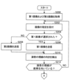
A-3.処理装置306Aの動作
図8は、処理装置306Aの動作を示すフローチャートである。図8のフローチャートでは、説明の便宜上、1台の端末装置40-iに対する画像送信処理が示される。処理装置306Aは、端末装置40-1~40-7のそれぞれに対して並列的に以下の処理を行っている。 A-3. Operation ofProcessing Device 306A FIG. 8 is a flow chart showing the operation of the processing device 306A. For convenience of explanation, the flowchart of FIG. 8 shows image transmission processing for one terminal device 40-i. The processing device 306A performs the following processing in parallel for each of the terminal devices 40-1 to 40-7.
図8は、処理装置306Aの動作を示すフローチャートである。図8のフローチャートでは、説明の便宜上、1台の端末装置40-iに対する画像送信処理が示される。処理装置306Aは、端末装置40-1~40-7のそれぞれに対して並列的に以下の処理を行っている。 A-3. Operation of
処理装置306Aは、画像取得部310として機能し、第1撮像装置10から第1画像PC1を、第2撮像装置20から第2画像PC2を、それぞれ取得する(ステップS100)。第1画像PC1および第2画像PC2の取得は、以降の処理中も継続して行われる。処理装置306Aは、送信制御部316Aとして機能し、視聴者Viの端末装置40-iに第2画像PC2を送信する(ステップS102)。
The processing device 306A functions as the image acquisition unit 310 and acquires the first image PC1 from the first imaging device 10 and the second image PC2 from the second imaging device 20 (step S100). Acquisition of the first image PC1 and the second image PC2 continues during subsequent processing. The processing device 306A functions as a transmission control unit 316A and transmits the second image PC2 to the terminal device 40-i of the viewer Vi (step S102).
処理装置306Aは、視線検出部312Aとして機能し、第2画像PC2に基づいて演者Pの視線の向きLを検出する(ステップS104)。処理装置306Aは、移動制御部314として機能し、演者Pの視線の延長線上に第1撮像装置10を移動させる(ステップS106)。
The processing device 306A functions as the line-of-sight detection unit 312A, and detects the line-of-sight direction L of the performer P based on the second image PC2 (step S104). The processing device 306A functions as the movement control unit 314, and moves the first imaging device 10 on the line of sight of the performer P (step S106).
また、処理装置306Aは、送信制御部316Aとして機能し、演者Pの視線の延長線上に座席Ciがあるか、すなわち、演者Pの視線が座席Ciを向いているか否かを判断する(ステップS108)。演者Pの視線が座席Ciに向いていない場合(ステップS108:NO)、処理装置306Aは、処理をステップS104に戻す。
Further, the processing device 306A functions as the transmission control unit 316A, and determines whether or not the seat Ci is on the extension line of the line of sight of the performer P, that is, whether or not the line of sight of the performer P faces the seat Ci (step S108). ). If the line of sight of the performer P is not directed toward the seat Ci (step S108: NO), the processing device 306A returns the process to step S104.
演者Pの視線が座席Ciに向いている場合(ステップS108:YES)、処理装置306Aは、送信制御部316Aとして機能し、座席Ciに対応する視聴者Viの端末装置40-iに第1画像PC1を送信する(ステップS110)。この時、処理装置306Aは、端末装置40-iにアラートを送信してもよい。
When the line of sight of the performer P is directed toward the seat Ci (step S108: YES), the processing device 306A functions as the transmission control unit 316A and transmits the first image to the terminal device 40-i of the viewer Vi corresponding to the seat Ci. PC1 is transmitted (step S110). At this time, the processing device 306A may send an alert to the terminal device 40-i.
処理装置306Aは、演者Pの視線が座席Ciから外れるまで待機する(ステップS112:NO)。この間、端末装置40-iには、第1画像PC1が送信される。演者Pの視線が座席Ciから外れると(ステップS112:YES)、処理装置306Aは、送信制御部316Aとして機能し、座席Ciに対応する視聴者Viの端末装置40-iに第2画像PC2を送信する(ステップS114)。その後、処理装置306Aは、ステップS100に処理を戻す。
The processing device 306A waits until the line of sight of the performer P leaves the seat Ci (step S112: NO). During this time, the first image PC1 is transmitted to the terminal device 40-i. When the actor P's line of sight moves away from the seat Ci (step S112: YES), the processing device 306A functions as the transmission control unit 316A, and transmits the second image PC2 to the terminal device 40-i of the viewer Vi corresponding to the seat Ci. It transmits (step S114). After that, the processing device 306A returns the processing to step S100.
以上説明したように、第1実施形態にかかる画像送信システム1によれば、演者Pの視線が、仮想的に設定された座席Ciを向いた場合に、当該座席Ciから演者Pを撮像した第1画像PC1を視聴者Viに送信する。視聴者Viは、ライブ会場において演者Pと目が合う、というリアルのライブ会場で起こり得る体験を、オンラインライブの視聴においても体験することができる。よって、オンラインライブの付加価値が向上する。
As described above, according to the image transmission system 1 according to the first embodiment, when the line of sight of the performer P faces the virtually set seat Ci, the image of the performer P is captured from the seat Ci. One image PC1 is transmitted to the viewer Vi. The viewer Vi can also experience the experience that can occur at a real live venue, such as making eye contact with the performer P at the live venue, in viewing the online live performance. Therefore, the added value of online live is improved.
また、画像送信システム1によれば、オンラインライブを視聴する視聴者Viに座席Ciが割り当てられる。よって、視聴者Viは、他の視聴者Vi+n(nは任意の整数)には視聴できない第1画像PC1を視聴することができ、実際にライブ会場に出向くのと同様の体験を得ることができる。
Also, according to the image transmission system 1, a seat Ci is assigned to the viewer Vi who watches the online live. Therefore, the viewer Vi can view the first image PC1 that other viewers Vi+n (n is an arbitrary integer) cannot view, and can obtain the same experience as actually going to the live venue. .
また、画像送信システム1において、端末装置40-iに送信される画像が第2画像PC2から第1画像PC1に切り替わる場合に、端末装置40-iにアラートを送信する。よって、視聴者Viが第1画像PC1を見逃す可能性が低減され、オンラインライブに対する満足度が更に向上する。
Also, in the image transmission system 1, when the image transmitted to the terminal device 40-i switches from the second image PC2 to the first image PC1, an alert is transmitted to the terminal device 40-i. Therefore, the viewer Vi is less likely to miss the first image PC1, and the degree of satisfaction with the online live performance is further improved.
また、第1実施形態では、1台の第1撮像装置10が、複数の座席C1~C7間を移動して第1画像PC1を撮像する。よって、複数台の撮像装置を配置するのと比較して、画像送信システム1のシステムコストが低減する。
Also, in the first embodiment, one first imaging device 10 moves between the plurality of seats C1 to C7 to capture the first image PC1. Therefore, the system cost of the image transmission system 1 is reduced compared to arranging a plurality of imaging devices.
また、第1実施形態では、第2撮像装置20が撮像した第2画像PC2に基づいて演者Pの視線の向きLを検出する。よって、演者Pの視線追跡用の撮像装置を別途配置するのと比較して、画像送信システム1のシステムコストが低減する。
Also, in the first embodiment, the line-of-sight direction L of the performer P is detected based on the second image PC2 captured by the second imaging device 20 . Therefore, the system cost of the image transmission system 1 is reduced as compared with the arrangement of an imaging device for tracking the line of sight of the performer P separately.
B.第2実施形態
以下、本発明の第2実施形態について説明する。なお、以下の説明では、説明の簡略化のため、第1実施形態と同一の構成要素に対しては、同一の符号を用いるとともに、その機能の説明を省略することがある。また、以下の説明では、説明の簡略化のため、主として、第2実施形態が、第1実施形態に比較して相違する点について説明する。 B. 2nd Embodiment Hereinafter, 2nd Embodiment of this invention is described. In the following description, for simplification of description, the same reference numerals are used for the same components as in the first embodiment, and the description of their functions may be omitted. Also, in the following description, for the sake of simplification of description, mainly the differences between the second embodiment and the first embodiment will be described.
以下、本発明の第2実施形態について説明する。なお、以下の説明では、説明の簡略化のため、第1実施形態と同一の構成要素に対しては、同一の符号を用いるとともに、その機能の説明を省略することがある。また、以下の説明では、説明の簡略化のため、主として、第2実施形態が、第1実施形態に比較して相違する点について説明する。 B. 2nd Embodiment Hereinafter, 2nd Embodiment of this invention is described. In the following description, for simplification of description, the same reference numerals are used for the same components as in the first embodiment, and the description of their functions may be omitted. Also, in the following description, for the sake of simplification of description, mainly the differences between the second embodiment and the first embodiment will be described.
B-1.システム構成
図9は、第2実施形態に係る画像送信システム2の構成を示すブロック図である。画像送信システム2は、複数の第1撮像装置10-1~10-7と、第2撮像装置20と、画像送信装置30Bとを備える。以下、第1撮像装置10-1~10-7のうち任意の1台を表す場合には、第1撮像装置10-i(i=1から7のうち任意の整数)と表記する。画像送信装置30Bは、通信網Nを介して複数の端末装置40(40-1,40-2…40-7)と接続されている。第2撮像装置20および端末装置40-1~40-7については、第1実施形態と同様であるため、説明を省略する。 B-1. System Configuration FIG. 9 is a block diagram showing the configuration of animage transmission system 2 according to the second embodiment. The image transmission system 2 includes a plurality of first imaging devices 10-1 to 10-7, a second imaging device 20, and an image transmission device 30B. Hereinafter, any one of the first imaging devices 10-1 to 10-7 will be referred to as the first imaging device 10-i (i=any integer from 1 to 7). The image transmission device 30B is connected via a communication network N to a plurality of terminal devices 40 (40-1, 40-2 . . . 40-7). Since the second imaging device 20 and the terminal devices 40-1 to 40-7 are the same as in the first embodiment, description thereof will be omitted.
図9は、第2実施形態に係る画像送信システム2の構成を示すブロック図である。画像送信システム2は、複数の第1撮像装置10-1~10-7と、第2撮像装置20と、画像送信装置30Bとを備える。以下、第1撮像装置10-1~10-7のうち任意の1台を表す場合には、第1撮像装置10-i(i=1から7のうち任意の整数)と表記する。画像送信装置30Bは、通信網Nを介して複数の端末装置40(40-1,40-2…40-7)と接続されている。第2撮像装置20および端末装置40-1~40-7については、第1実施形態と同様であるため、説明を省略する。 B-1. System Configuration FIG. 9 is a block diagram showing the configuration of an
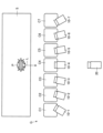
図10は、第2実施形態における第1撮像装置10-1~10-7の配置を模式的に示す説明図である。図10は、劇場Gを上方から見た図である。第1撮像装置10-1~10-7は、劇場G内の座席C1~C7の位置にそれぞれ設置されている。それぞれの第1撮像装置10-1~10-7は、座席C1~C7の位置に固定されている。例えば、第1撮像装置10-1は、座席C1の位置に固定されており、第1撮像装置10-2は、座席C2の位置に固定されている。なお、固定されている、とは、劇場G内を他の座席Ciの方向に移動しない、との意味である。例えば、第1撮像装置10-iは、パン、チルトなどの首振り、上下の移動などが可能であってもよい。
FIG. 10 is an explanatory diagram schematically showing the arrangement of the first imaging devices 10-1 to 10-7 in the second embodiment. FIG. 10 is a view of Theater G viewed from above. The first imaging devices 10-1 to 10-7 are installed at the positions of seats C1 to C7 in the theater G, respectively. The respective first imaging devices 10-1 to 10-7 are fixed at the positions of the seats C1 to C7. For example, the first imaging device 10-1 is fixed at the position of the seat C1, and the first imaging device 10-2 is fixed at the position of the seat C2. Note that "fixed" means that the seat does not move in the theater G toward another seat Ci. For example, the first imaging device 10-i may be capable of swinging such as panning and tilting, and moving up and down.
第1撮像装置10-iは、座席Ciから舞台Sを見た画像を、第1画像PC1-iとして撮像する。第1撮像装置10-iの撮像範囲は、例えば舞台S全体が映るように設定されていてもよいし、演者Pの顔がアップで映るように設定されていてもよい。演者Pの顔がアップで映るように設定されている場合、第1撮像装置10-iは、例えば、パン、チルト、ズーム等を遠隔操作で行うための補助機構が設けられているのが好ましい。
The first imaging device 10-i captures an image of the stage S viewed from the seat Ci as a first image PC1-i. The imaging range of the first imaging device 10-i may be set, for example, to capture the entire stage S, or may be set to capture the face of the performer P in close-up. When the face of the performer P is set to be close-up, the first imaging device 10-i is preferably provided with an auxiliary mechanism for performing panning, tilting, zooming, etc. by remote control, for example. .
B-2.画像送信装置30B
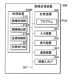
図11は、画像送信装置30Bの構成を示すブロック図である。画像送信装置30Bは、入力装置301と、表示装置302と、通信装置303と、画像入力インターフェース304と、記憶装置305と、処理装置306Bと、バス307とを含む。入力装置301と、表示装置302と、通信装置303と、画像入力インターフェース304と、バス307とは、第1実施形態の画像送信装置30Aと同様のため、説明を省略する。 B-2.Image transmission device 30B
FIG. 11 is a block diagram showing the configuration of theimage transmission device 30B. The image transmission device 30B includes an input device 301, a display device 302, a communication device 303, an image input interface 304, a storage device 305, a processing device 306B, and a bus 307. Since the input device 301, the display device 302, the communication device 303, the image input interface 304, and the bus 307 are the same as those of the image transmission device 30A of the first embodiment, description thereof will be omitted.
図11は、画像送信装置30Bの構成を示すブロック図である。画像送信装置30Bは、入力装置301と、表示装置302と、通信装置303と、画像入力インターフェース304と、記憶装置305と、処理装置306Bと、バス307とを含む。入力装置301と、表示装置302と、通信装置303と、画像入力インターフェース304と、バス307とは、第1実施形態の画像送信装置30Aと同様のため、説明を省略する。 B-2.
FIG. 11 is a block diagram showing the configuration of the
記憶装置305は、記憶装置305は、プログラムPG2を記憶する。プログラムPG2は、画像送信装置30Bを動作させるためのプログラムである。
The storage device 305 stores the program PG2. The program PG2 is a program for operating the image transmission device 30B.
処理装置306Bは、プログラムPG2を実行することによって、画像取得部310、視線検出部312B、送信制御部316Bおよび指定受付部320として機能する。画像取得部310、視線検出部312B、送信制御部316Bおよび指定受付部320のうち少なくとも1つは、DSP、ASIC、PLDおよびFPGA等の回路によって構成されてもよい。
The processing device 306B functions as an image acquisition unit 310, a line-of-sight detection unit 312B, a transmission control unit 316B, and a designation reception unit 320 by executing the program PG2. At least one of the image acquisition unit 310, line-of-sight detection unit 312B, transmission control unit 316B, and designation reception unit 320 may be configured by circuits such as DSP, ASIC, PLD, and FPGA.
画像取得部310は、第1実施形態と同様に機能する。
The image acquisition unit 310 functions in the same manner as in the first embodiment.
指定受付部320は、端末装置40-iに送信する画像を、第1画像PC1または第2画像PC2のいずれにするかの指定を、視聴者Viから受け付ける。ここで、第1実施形態では、1台の第1撮像装置10が複数の座席C1~C7間を移動していた。これに対して、第2実施形態では、第1撮像装置10-1~10-7が各座席C1~C7に設置されており、任意の座席Ciから舞台Sを見た画像が常時取得可能である。端末装置40-iに送信する画像の指定を受け付けることで、視聴者Viは、自身に対応付けられている座席Ciからの実演の鑑賞が可能となる。
The designation receiving unit 320 receives from the viewer Vi a designation as to whether the image to be transmitted to the terminal device 40-i is the first image PC1 or the second image PC2. Here, in the first embodiment, one first imaging device 10 moves between the plurality of seats C1 to C7. On the other hand, in the second embodiment, the first imaging devices 10-1 to 10-7 are installed in the respective seats C1 to C7, and images of the stage S viewed from any seat Ci can always be obtained. be. By accepting the designation of the image to be transmitted to the terminal device 40-i, the viewer Vi can appreciate the performance from the seat Ci associated with the viewer Vi.
図12Aおよび図12Bは、端末装置40-1におけるオンラインライブの視聴画面の一例を示す説明図である。図12Aおよび図12Bでは、端末装置40-iの一例として、座席C1に対応付けられた端末装置40-1を例にして説明する。端末装置40-1は、例えばスマートフォンである。例えば図10に示すように、演者Pが座席C4を向いている場合について検討する。
FIGS. 12A and 12B are explanatory diagrams showing examples of online live viewing screens on the terminal device 40-1. 12A and 12B, the terminal device 40-1 associated with the seat C1 will be described as an example of the terminal device 40-i. The terminal device 40-1 is, for example, a smart phone. For example, as shown in FIG. 10, consider the case where the performer P faces seat C4.
端末装置40-1で第2画像PC2を視聴している場合、端末装置40-1のディスプレイ400には、図12Aに示すように、舞台Sに対して正面から撮像され、演者Pの全身が映る画像が表示される。また、ディスプレイ400には、画像切替用の第1ボタンB1が表示される。第1ボタンB1は、端末装置40-1に対応付けられた座席C1に設置されている第1撮像装置10-1が撮像した第1画像PC1-1への表示切替ボタンである。
When the second image PC2 is viewed on the terminal device 40-1, the display 400 of the terminal device 40-1 shows the whole body of the performer P captured from the front of the stage S as shown in FIG. 12A. The projected image is displayed. The display 400 also displays a first button B1 for image switching. The first button B1 is a button for switching the display to the first image PC1-1 captured by the first imaging device 10-1 installed on the seat C1 associated with the terminal device 40-1.
視聴者V1が第1ボタンB1を押下すると、図12Bに示すように、ディスプレイ400には第1画像PC1-1が表示される。第1画像PC1-1には、座席C4方向に視線を向ける演者Pを座席C1から撮像した画像が表示される。また、ディスプレイ400には、画像切替用の第2ボタンB2が表示される。第2ボタンB2は、第2撮像装置20が撮像した第2画像PC2への表示切替ボタンである。視聴者V1が第2ボタンB2を押下すると、ディスプレイ400には、図12Aに示すような第2画像PC2が表示される。
When the viewer V1 presses the first button B1, the display 400 displays the first image PC1-1 as shown in FIG. 12B. In the first image PC1-1, an image of the performer P whose line of sight is directed toward the seat C4 is captured from the seat C1. The display 400 also displays a second button B2 for image switching. The second button B<b>2 is a button for switching the display to the second image PC<b>2 captured by the second imaging device 20 . When the viewer V1 presses the second button B2, the display 400 displays the second image PC2 as shown in FIG. 12A.
視線検出部312Bは、演者Pの視線の向きLを検出する。視線検出部312Bは、検出部の一例である。第2実施形態では、視線検出部312Bは、第1画像PC1に基づいて演者Pの視線の向きLを検出する。視線検出部312Bは、第1画像PC1-1~PC1-7に対してそれぞれ画像解析を行う方法で、舞台S上における演者Pの位置および演者Pの顔の向きを検出する。視線検出部31は、例えば演者Pの顔が正面を向いている画像を撮像している第1撮像装置10-iの方向に、演者Pの視線が向いていると推定する。または、視線検出部312Bは、第1画像PC1-1~PC1-7から更に演者Pの黒目の位置を検出して、演者Pの視線の向きLを更に詳細に検出してもよい。
The line-of-sight detection unit 312B detects the line-of-sight direction L of the performer P. The line-of-sight detection unit 312B is an example of a detection unit. In the second embodiment, the line-of-sight detection unit 312B detects the line-of-sight direction L of the performer P based on the first image PC1. The line-of-sight detection unit 312B detects the position of the performer P on the stage S and the face orientation of the performer P by a method of performing image analysis on each of the first images PC1-1 to PC1-7. The line-of-sight detection unit 31 estimates that the line-of-sight of the performer P is directed toward the first imaging device 10-i capturing an image in which the face of the performer P faces the front, for example. Alternatively, the line-of-sight detection unit 312B may further detect the position of the iris of the performer P from the first images PC1-1 to PC1-7 to detect the line-of-sight direction L of the performer P in more detail.
なお、第2実施形態においても、第1実施形態と同様に、第2画像PC2に基づいて演者Pの視線の向きLが検出されてもよい。
Also in the second embodiment, as in the first embodiment, the line-of-sight direction L of the performer P may be detected based on the second image PC2.
送信制御部316Bは、端末装置40-1~40-7に対して演者Pを撮像した画像を送信する。演者Pを撮像した画像とは、第1画像PC1または第2画像PC2である。送信制御部316Bは、指定受付部320が受け付けた指定結果に基づいて、端末装置40-1~40-7に送信する画像を、第1画像PC1と第2画像PC2との間で切り替える。すなわち、端末装置40-1~40-7に送信する画像は、端末装置40-1~40-7ごとに互いに異なる。
The transmission control unit 316B transmits the captured image of the performer P to the terminal devices 40-1 to 40-7. The image obtained by imaging the performer P is the first image PC1 or the second image PC2. The transmission control unit 316B switches the image to be transmitted to the terminal devices 40-1 to 40-7 between the first image PC1 and the second image PC2 based on the designation result received by the designation receiving unit 320. FIG. That is, the images transmitted to the terminal devices 40-1 to 40-7 are different for each of the terminal devices 40-1 to 40-7.
送信制御部316Bは、通常時は、端末装置40-iに対して、第1画像PC1または第2画像PC2のうち、視聴者Viが指定した画像を送信する。通常時とは、演者Pの視線の向きLが、端末装置40-iに対応付けられた座席Ciを向いていない時である。一方、送信制御部316Bは、演者Pの視線の向きLが、端末装置40-iに対応する座席Ciを向いた場合、視聴者Viが行った指定に関わらず、端末装置40-iに対して、第1画像PC1-iを送信する。
The transmission control unit 316B normally transmits to the terminal device 40-i the image specified by the viewer Vi, either the first image PC1 or the second image PC2. The normal time is when the line-of-sight direction L of the performer P is not facing the seat Ci associated with the terminal device 40-i. On the other hand, when the line-of-sight direction L of the performer P faces the seat Ci corresponding to the terminal device 40-i, the transmission control unit 316B controls the terminal device 40-i regardless of the designation made by the viewer Vi. to transmit the first image PC1-i.
図13は、送信制御部316Bが行う送信画像の切り替えを模式的に示す説明図である。図13は、例えば端末装置40-1への送信画像を示す。以下、時刻t11からt12にかけて、演者Pは、端末装置40-1に対応付けられた座席C1に視線を向けた場合について検討する。
FIG. 13 is an explanatory diagram schematically showing switching of transmission images performed by the transmission control unit 316B. FIG. 13 shows an image transmitted to the terminal device 40-1, for example. Below, the case where the performer P looks at the seat C1 associated with the terminal device 40-1 from time t11 to t12 will be considered.
例えば、図中の「第2画像指定時」は、時刻t11の直前において、視聴者V1が第2画像PC2を指定している場合を示す。送信制御部316Bは、時刻t11までは端末装置40-1に第2画像PC2を送信する。送信制御部316Bは、演者Pの視線が座席C1を向いている時刻t11からt12の間は、端末装置40-1に第1画像PC1-1を送信する。送信制御部316Bは、端末装置40-1における表示画像が第1画像PC1-1に切り替える前に、アラートを送信してもよい(図中符号N)。送信制御部316Bは、演者Pの視線が座席C1から外れた時刻t12の以降は、端末装置40-1に送信する画像を第2画像PC2に戻す。
For example, "When specifying the second image" in the figure indicates the case where the viewer V1 specifies the second image PC2 immediately before time t11. The transmission control unit 316B transmits the second image PC2 to the terminal device 40-1 until time t11. The transmission control unit 316B transmits the first image PC1-1 to the terminal device 40-1 from time t11 to t12 when the line of sight of the performer P is directed toward the seat C1. The transmission control unit 316B may transmit an alert (symbol N in the drawing) before the display image on the terminal device 40-1 is switched to the first image PC1-1. The transmission control unit 316B returns the image to be transmitted to the terminal device 40-1 to the second image PC2 after time t12 when the line of sight of the performer P is removed from the seat C1.
また、図中の「第1画像指定時」は、時刻t11の直前において、視聴者V1が第1画像PC1を指定している場合を示す。送信制御部316Bは、時刻t11の時点で端末装置40-1に第1画像PC1-1を送信している。また、送信制御部316Bは、演者Pの視線が座席C1を向いている時刻t11からt12の間も、端末装置40-1に第1画像PC1-1の送信を継続する。また、送信制御部316Bは、演者Pの視線が座席C1から外れた時刻t12の以降も、端末装置40-1に第1画像PC1-1を送信する。なお、送信制御部316Bは、演者Pの視線が座席C1を向く時刻t11の以前に、端末装置40-1にアラートを送信するのが好ましい(図中符号N)。よって、視聴者V1は、演者Pの視線が座席C1に向くことを認識することができ、カメラ目線の画像の見逃しを防止できる。
"When specifying the first image" in the figure indicates the case where the viewer V1 specifies the first image PC1 immediately before time t11. The transmission control unit 316B has transmitted the first image PC1-1 to the terminal device 40-1 at time t11. The transmission control unit 316B also continues to transmit the first image PC1-1 to the terminal device 40-1 during the period from time t11 to t12 when the line of sight of the performer P is directed toward the seat C1. The transmission control unit 316B also transmits the first image PC1-1 to the terminal device 40-1 after time t12 when the line of sight of the performer P leaves the seat C1. It is preferable that the transmission control unit 316B transmits an alert to the terminal device 40-1 before the time t11 when the line of sight of the performer P faces the seat C1 (symbol N in the figure). Therefore, the viewer V1 can recognize that the line of sight of the performer P is directed to the seat C1, and can prevent overlooking the image of the camera line of sight.
B-3.処理装置306Bの動作
図14および図14Bは、処理装置306Bの動作を示すフローチャートである。図14および図14Bのフローチャートでは、説明の便宜上、1台の端末装置40-iに対する画像送信に着目する。処理装置306Bは、端末装置40-1~40-7のそれぞれに対して並列的に以下の処理を行っている。 B-3. Operation ofProcessing Unit 306B FIGS. 14 and 14B are flow charts showing the operation of processing unit 306B. In the flowcharts of FIGS. 14 and 14B, for convenience of explanation, attention is paid to image transmission to one terminal device 40-i. The processing device 306B performs the following processing in parallel for each of the terminal devices 40-1 to 40-7.
図14および図14Bは、処理装置306Bの動作を示すフローチャートである。図14および図14Bのフローチャートでは、説明の便宜上、1台の端末装置40-iに対する画像送信に着目する。処理装置306Bは、端末装置40-1~40-7のそれぞれに対して並列的に以下の処理を行っている。 B-3. Operation of
処理装置306Bは、画像取得部310として機能し、第1撮像装置10から第1画像PC1を、第2撮像装置20から第2画像PC2を、それぞれ取得する(ステップS200)。第1画像PC1および第2画像PC2の取得は、以降の処理中も継続して行われる。
The processing device 306B functions as the image acquisition unit 310 and acquires the first image PC1 from the first imaging device 10 and the second image PC2 from the second imaging device 20 (step S200). Acquisition of the first image PC1 and the second image PC2 continues during subsequent processing.
処理装置306Bは、指定受付部320として機能し、視聴者Viから端末装置40-iに送信する画像を、第1画像PC1または第2画像PC2のいずれにするかの指定を受け付ける(ステップS202)。第1画像PC1が選択された場合(ステップS204:YES)、処理装置306Bは、送信制御部316Bとして機能し、端末装置40-iに第1画像PC1を送信する(ステップS206)。また、第1画像PC1が選択されかった場合(ステップS204:NO、すなわち、第2画像PC2が選択された場合、処理装置306Bは、送信制御部316Bとして機能し、端末装置40に第2画像PC2を送信する(ステップS208)。
The processing device 306B functions as the designation reception unit 320, and receives designation of whether the image to be transmitted from the viewer Vi to the terminal device 40-i is the first image PC1 or the second image PC2 (step S202). . When the first image PC1 is selected (step S204: YES), the processing device 306B functions as the transmission control unit 316B and transmits the first image PC1 to the terminal device 40-i (step S206). Further, when the first image PC1 is not selected (step S204: NO, that is, when the second image PC2 is selected, the processing device 306B functions as the transmission control unit 316B and transmits the second image PC1 to the terminal device 40. PC2 is transmitted (step S208).
処理装置306Bは、視線検出部312Bとして機能し、第1画像PC1に基づいて演者Pの視線の向きLを検出する(ステップS210)。処理装置306Bは、送信制御部316Bとして機能し、演者Pの視線の延長線上に座席Ciがあるか、すなわち、演者Pの視線が座席Ciを向いているか否かを判断する(ステップS212)。演者Pの視線が座席Ciに向いていない場合(ステップS212:NO)、処理装置306Bは、処理をステップS202に戻す。
The processing device 306B functions as the line-of-sight detection unit 312B, and detects the line-of-sight direction L of the performer P based on the first image PC1 (step S210). The processing device 306B functions as the transmission control unit 316B, and determines whether the seat Ci is on an extension of the line of sight of the performer P, that is, whether the line of sight of the performer P faces the seat Ci (step S212). If the line of sight of the performer P is not directed toward the seat Ci (step S212: NO), the processing device 306B returns the process to step S202.
演者Pの視線が座席Ciに向いている場合(ステップS212:YES)、処理装置306Bは、送信制御部316Bとして機能し、座席Ciに対応する端末装置40-iに送信しているのが第2画像PC2か否かを判断する(ステップS214)。端末装置40-iに送信しているのが第2画像PC2の場合(ステップS214:YES)、処理装置306Bは、端末装置40-iに第1画像PC1を送信する(ステップS216)。すなわち、端末装置40-iへの送信画像を、第2画像PC2から第1画像PC1に切り替える。この時、処理装置306Bは、端末装置40-iにアラートを送信してもよい。
When the line of sight of the performer P is directed toward the seat Ci (step S212: YES), the processing device 306B functions as the transmission control unit 316B, and transmits to the terminal device 40-i corresponding to the seat Ci. It is determined whether or not it is two-image PC2 (step S214). If the image being transmitted to the terminal device 40-i is the second image PC2 (step S214: YES), the processing device 306B transmits the first image PC1 to the terminal device 40-i (step S216). That is, the image to be transmitted to the terminal device 40-i is switched from the second image PC2 to the first image PC1. At this time, the processing device 306B may send an alert to the terminal device 40-i.
処理装置306Bは、演者Pの視線が座席Ciから外れるまで待機する(ステップS218:NO)。この間、端末装置40-iには、第1画像PC1が送信される。演者Pの視線が座席Ciら外れると(ステップS218:YES)、処理装置306Bは、送信制御部316Bとして機能し、端末装置40-iに第2画像PC2を送信する(ステップS220)。その後、処理装置306Bは、ステップS200に処理を戻す。
The processing device 306B waits until the line of sight of the performer P is removed from the seat Ci (step S218: NO). During this time, the first image PC1 is transmitted to the terminal device 40-i. When the line of sight of the performer P leaves the seat Ci (step S218: YES), the processing device 306B functions as the transmission control unit 316B and transmits the second image PC2 to the terminal device 40-i (step S220). After that, the processing device 306B returns the processing to step S200.
また、ステップS214において、端末装置40-iに送信しているのが第2画像PC2ではない場合(ステップS214:NO)、すなわち、第1画像PC1の場合、処理装置306Bは、端末装置40-iにアラートを送信する(ステップS222)。その後、処理装置306Bは、ステップS200に処理を戻す。
Further, in step S214, if the image being transmitted to the terminal device 40-i is not the second image PC2 (step S214: NO), that is, in the case of the first image PC1, the processing device 306B sends the terminal device 40-i An alert is sent to i (step S222). After that, the processing device 306B returns the processing to step S200.
以上説明したように、第2実施形態では、各座席C1~C7に対応して第1撮像装置10-1~10-7が配置されている。よって、視聴者Viは、自身に対応付けられた座席Ciからの撮像画像(第1画像PC1-i)を任意のタイミングで視聴することができ、実際のライブに近い視聴体験を得ることができる。また、各座席C1~C7に対応して第1撮像装置10-1~10-7が配置されていることに起因して、より確実に演者Pの視線が向いた画像を撮像することができる。よって、オンラインライブに対する視聴者Viの満足度が向上する。
As described above, in the second embodiment, the first imaging devices 10-1 to 10-7 are arranged corresponding to the respective seats C1 to C7. Therefore, the viewer Vi can view the captured image (first image PC1-i) from the seat Ci associated with the viewer Vi at any timing, and can obtain a viewing experience close to an actual live performance. . In addition, since the first imaging devices 10-1 to 10-7 are arranged corresponding to the respective seats C1 to C7, it is possible to more reliably capture an image in which the line of sight of the performer P is directed. . Therefore, the degree of satisfaction of the viewers Vi with respect to the online live performance is improved.
また、第2実施形態では、第1撮像装置10-1~10-7が撮像した第1画像PC1-1~PC1-7に基づいて演者Pの視線の向きLを検出する。よって、1台の撮像装置で撮像した画像に基づいて演者Pの視線を追跡するのと比較して、演者Pの視線の向きLがより精度よく検出される。
Further, in the second embodiment, the gaze direction L of the performer P is detected based on the first images PC1-1 to PC1-7 captured by the first imaging devices 10-1 to 10-7. Therefore, the line-of-sight direction L of the performer P can be detected more accurately than when the line-of-sight of the performer P is tracked based on an image captured by a single imaging device.
C.変形例
上述の実施形態における変形の態様を以下に示す。以下の変形の態様から任意に選択された2以上の態様を、相互に矛盾しない範囲において適宜に併合してもよい。 C. Modifications Modifications of the above-described embodiment are shown below. Two or more aspects arbitrarily selected from the following modified aspects may be combined as appropriate within a mutually consistent range.
上述の実施形態における変形の態様を以下に示す。以下の変形の態様から任意に選択された2以上の態様を、相互に矛盾しない範囲において適宜に併合してもよい。 C. Modifications Modifications of the above-described embodiment are shown below. Two or more aspects arbitrarily selected from the following modified aspects may be combined as appropriate within a mutually consistent range.
C1.第1変形例
第1変形例は、図9~図11に示す第2実施形態の構成が援用される。上述した実施形態では、演者Pが1人である場合について説明した。一方で、演者Pがバンドまたはグループ等のメンバーである場合、複数人の演者Pが舞台Sに上がる場合がある。この場合、演者Pの人数によっては、いずれかの演者Pの視線が座席Ciに向けられることが頻繁に起こり得る。また、視聴者Viが複数人のメンバーのうち、特定のメンバーのみに興味がある場合もある。すなわち、複数人の演者P全てに対して上述した制御を行うと、返って実演が見づらくなったり、視聴者Viの満足度が下がったりする可能性がある。 C1. First Modification The first modification employs the configuration of the second embodiment shown in FIGS. In the above-described embodiment, the case where there is one performer P has been described. On the other hand, when the performers P are members of a band, group, or the like, a plurality of performers P may appear on the stage S. In this case, depending on the number of performers P, one of the performers P's line of sight may frequently be directed toward the seat Ci. Also, the viewer Vi may be interested only in a specific member out of a plurality of members. That is, if the above-described control is performed on all of the plurality of performers P, it may become difficult to watch the performance, or the degree of satisfaction of the viewers Vi may decrease.
第1変形例は、図9~図11に示す第2実施形態の構成が援用される。上述した実施形態では、演者Pが1人である場合について説明した。一方で、演者Pがバンドまたはグループ等のメンバーである場合、複数人の演者Pが舞台Sに上がる場合がある。この場合、演者Pの人数によっては、いずれかの演者Pの視線が座席Ciに向けられることが頻繁に起こり得る。また、視聴者Viが複数人のメンバーのうち、特定のメンバーのみに興味がある場合もある。すなわち、複数人の演者P全てに対して上述した制御を行うと、返って実演が見づらくなったり、視聴者Viの満足度が下がったりする可能性がある。 C1. First Modification The first modification employs the configuration of the second embodiment shown in FIGS. In the above-described embodiment, the case where there is one performer P has been described. On the other hand, when the performers P are members of a band, group, or the like, a plurality of performers P may appear on the stage S. In this case, depending on the number of performers P, one of the performers P's line of sight may frequently be directed toward the seat Ci. Also, the viewer Vi may be interested only in a specific member out of a plurality of members. That is, if the above-described control is performed on all of the plurality of performers P, it may become difficult to watch the performance, or the degree of satisfaction of the viewers Vi may decrease.
このため、舞台Sにいる演者Pが複数の場合には、座席Ciに目を向けた場合に第1画像PC1に切り替える演者Pを視聴者Viが指定できるようにしてもよい。例えば、第1演者P1と、第1演者P1とともに実演する第2演者P2とが舞台Sに上がっている。図11に示す画像送信装置30Bは、指定受付部320によって、視聴者Viから、第1演者P1または第2演者P2の指定を受け付ける。指定受付部320は、受付部の一例である。第1撮像装置10-iは、視聴者Viから第1演者P1が指定された場合は、第1演者P1を追尾して、第1演者P1が写る第1画像を撮像する。また、第1撮像装置10-iは、視聴者Viから第2演者P2が指定された場合は、第2演者P2を追尾して、第2演者P2が写る第1画像を撮像する。
Therefore, when there are a plurality of performers P on the stage S, the viewer Vi may be allowed to specify the performer P to switch to the first image PC1 when looking at the seat Ci. For example, a first performer P1 and a second performer P2 performing together with the first performer P1 are on stage S. The image transmission device 30B shown in FIG. 11 receives the designation of the first performer P1 or the second performer P2 from the viewer Vi by the designation reception unit 320. FIG. The designation reception unit 320 is an example of a reception unit. When the viewer Vi designates the first performer P1, the first imaging device 10-i tracks the first performer P1 and captures a first image showing the first performer P1. Further, when the viewer Vi designates the second performer P2, the first imaging device 10-i tracks the second performer P2 and captures the first image showing the second performer P2.
視線検出部312Bは、第1演者P1の視線の向きLおよび第2演者の視線の向きLを検出する。送信制御部316Bは、視聴者Viから第1演者P1が指定され、かつ第1演者P1の視線が座席Ciに向いたことに基づいて、端末装置40-iに第1画像PC1を送信する。送信制御部316Bは、視聴者Viから第2演者P2が指定され、かつ第2演者P2の視線が仮想的な座席Ciに向いたことに基づいて、端末装置40-iに第1画像PC1を送信する、
The line-of-sight detection unit 312B detects the line-of-sight direction L of the first performer P1 and the line-of-sight direction L of the second performer P1. The transmission control unit 316B transmits the first image PC1 to the terminal device 40-i based on the fact that the first performer P1 is designated by the viewer Vi and the line of sight of the first performer P1 is directed toward the seat Ci. The transmission control unit 316B transmits the first image PC1 to the terminal device 40-i based on the fact that the viewer Vi designates the second performer P2 and the line of sight of the second performer P2 is directed toward the virtual seat Ci. Send,
言い換えると、送信制御部316Bは、視聴者Viから指定された演者P(以下、指定演者PXという)が座席Ciに目を向けた場合には、端末装置40-iに送信する画像を第1画像PC1に切り替える。一方、指定演者PX以外の演者Pが座席Ciに目を向けた場合、送信制御部316Bは、端末装置40-iに送信する画像の切り替えを行わない。
In other words, when the performer P designated by the viewer Vi (hereinafter referred to as the designated performer PX) looks toward the seat Ci, the transmission control unit 316B sends the image to be transmitted to the terminal device 40-i to the first Switch to image PC1. On the other hand, when a performer P other than the designated performer PX looks toward the seat Ci, the transmission control unit 316B does not switch the image to be transmitted to the terminal device 40-i.
第1変形例によれば、視聴者Viが指定した演者Pが座席Ciに視線を向けた場合にのみ、第1画像PC1への切り替えが行われる。よって、端末装置40-iに送信される画像が、頻繁に切り替えられるのを防止できる。また、視聴者Viは、注目したい演者Pの実演を見逃すことなく視聴できる。
According to the first modification, switching to the first image PC1 is performed only when the performer P specified by the viewer Vi turns his or her line of sight toward the seat Ci. Therefore, it is possible to prevent the image transmitted to the terminal device 40-i from being frequently switched. In addition, the viewer Vi can watch the performance of the performer P to watch without missing it.
なお、第1変形例は、第2実施形態の構成が援用されたが、例えば、視聴者Viが1人の場合、または視聴者Vi全員が同じ演者P(例えば第1演者P1)を指定した場合等には、第1実施形態の構成が援用されてもよい。
Although the configuration of the second embodiment is used in the first modification, for example, when there is only one viewer Vi, or when all viewers Vi designate the same performer P (for example, the first performer P1) In some cases, the configuration of the first embodiment may be used.
C2.第2変形例
上述した実施形態では、送信制御部316Aは、演者Pの視線が座席Ciを向いたタイミングで端末装置40-iに送信する画像を第1画像PC1に切り替えた。これに限らず、演者Pの視線が座席Ciを向くより前に、第1画像PC1に切り替えてもよい。 C2. Second Modification In the embodiment described above, thetransmission control unit 316A switches the image to be transmitted to the terminal device 40-i to the first image PC1 at the timing when the line of sight of the performer P faces the seat Ci. The present invention is not limited to this, and may be switched to the first image PC1 before the line of sight of the performer P turns to the seat Ci.
上述した実施形態では、送信制御部316Aは、演者Pの視線が座席Ciを向いたタイミングで端末装置40-iに送信する画像を第1画像PC1に切り替えた。これに限らず、演者Pの視線が座席Ciを向くより前に、第1画像PC1に切り替えてもよい。 C2. Second Modification In the embodiment described above, the
図15は、第2変形例を模式的に示す説明図である。図15では、第1撮像装置10および第2撮像装置20の図示を省略している。座席C1~C7には、それぞれ画像切替範囲H1~H7が設定されている。画像切替範囲H1~H7の広さは、座席C1~C7の範囲よりも左右に広く設定されている。例えば、演者Pの視線が画像切替範囲H1に入った場合には、端末装置40-1に第1画像PC1が送信される。上述のように、画像切替範囲H1~H7の広さは、座席C1~C7の範囲よりも広く設定されているので、端末装置40-1への第1画像PC1の送信が開始されるのは、演者Pが座席C1を向くよりも早いタイミングである。また、端末装置40-1への第1画像PC1の送信が終了するのは、演者Pの視線が座席C1を離れてから若干時間が経過してからである。例えば、図15のように、演者Pが画像切替範囲H3およびH4の重複範囲に視線を向けている場合には、座席C3に対応する端末装置40-3および座席C4に対応する端末装置40-4に、第1画像PC1が送信される。
FIG. 15 is an explanatory diagram schematically showing the second modified example. In FIG. 15, illustration of the first imaging device 10 and the second imaging device 20 is omitted. Image switching ranges H1 to H7 are set for the seats C1 to C7, respectively. The width of the image switching range H1 to H7 is set wider to the left and right than the range of the seats C1 to C7. For example, when the line of sight of the performer P enters the image switching range H1, the first image PC1 is transmitted to the terminal device 40-1. As described above, the image switching range H1 to H7 is set to be wider than the range of the seats C1 to C7, so transmission of the first image PC1 to the terminal device 40-1 is started at , earlier than when the performer P turns to the seat C1. Also, the transmission of the first image PC1 to the terminal device 40-1 ends after a certain amount of time has passed since the line of sight of the performer P left the seat C1. For example, as shown in FIG. 15, when the performer P is looking at the overlapping range of the image switching ranges H3 and H4, the terminal device 40-3 corresponding to the seat C3 and the terminal device 40- corresponding to the seat C4 4, the first image PC1 is transmitted.
第2変形例によれば、視聴者Viは、演者Pが自身に対応する座席Ciに目を向ける様子を見ることができ、演者Pと目が合う感覚を、よりリアルに体感できる。
According to the second modified example, the viewer Vi can see how the performer P turns his/her eyes to the seat Ci corresponding to him/herself, and can more realistically experience the sensation of making eye contact with the performer P.
C3.第3変形例
上述した実施形態では、第1撮像装置10で撮像した第1画像PC1、または第2撮像装置20で撮像した第2画像PC2に基づいて、演者Pの視線の向きLを検出した。これに限らず、演者Pの視線の向きLを検出するための画像を撮像する第3撮像装置を設けてもよい。第3撮像装置は、例えば、第1撮像装置10よりも舞台Sに近い位置に配置された撮像装置であってもよい。また、第3撮像装置は、例えば、演者Pが実演中に装着するXR(Extended Reality)グラスに搭載された撮像装置であってもよい。また、第3撮像装置は、例えば、演者Pの視線追跡に特化したアイトラッキング装置に搭載された撮像装置であってもよい。 C3. Third Modification In the embodiment described above, the line-of-sight direction L of the performer P is detected based on the first image PC1 captured by thefirst imaging device 10 or the second image PC2 captured by the second imaging device 20. . Not limited to this, a third imaging device that captures an image for detecting the line-of-sight direction L of the performer P may be provided. The third imaging device may be, for example, an imaging device arranged closer to the stage S than the first imaging device 10 . Also, the third imaging device may be, for example, an imaging device mounted on XR (Extended Reality) glasses that the performer P wears during the performance. Also, the third imaging device may be, for example, an imaging device mounted on an eye tracking device specialized for tracking the performer P's line of sight.
上述した実施形態では、第1撮像装置10で撮像した第1画像PC1、または第2撮像装置20で撮像した第2画像PC2に基づいて、演者Pの視線の向きLを検出した。これに限らず、演者Pの視線の向きLを検出するための画像を撮像する第3撮像装置を設けてもよい。第3撮像装置は、例えば、第1撮像装置10よりも舞台Sに近い位置に配置された撮像装置であってもよい。また、第3撮像装置は、例えば、演者Pが実演中に装着するXR(Extended Reality)グラスに搭載された撮像装置であってもよい。また、第3撮像装置は、例えば、演者Pの視線追跡に特化したアイトラッキング装置に搭載された撮像装置であってもよい。 C3. Third Modification In the embodiment described above, the line-of-sight direction L of the performer P is detected based on the first image PC1 captured by the
このような変形例によれば、演者Pの視線の向きLを検出するのに特化した画像に基づいて演者Pの視線の向きLを検出するので、演者Pの視線の向きLがより精度良く検出される。また、第1撮像装置10または第2撮像装置20が常時演者Pを撮像しなくてもよいので、例えば、実演中の演出に合わせて演者P以外を撮像するなどが可能となり、オンラインライブの視覚表現の自由度を向上させることができる。
According to such a modification, since the direction L of the line of sight of the performer P is detected based on the image specialized for detecting the direction L of the line of sight of the performer P, the direction L of the line of sight of the performer P can be detected more accurately. well detected. In addition, since the first imaging device 10 or the second imaging device 20 does not always have to image the performer P, for example, it is possible to image other than the performer P according to the performance during the performance, and the online live visual The degree of freedom of expression can be improved.
また、画像から演者Pの視線の向きLを検出するのではなく、例えば、演者Pの頭部に装着されたセンサの検出値に基づいて、演者Pの視線の向きLを算出してもよい。この場合のセンサとは、例えば、慣性計測装置(IMU:Inertial Measurement Unit)または地磁気センサ等を用いることができる。
Further, instead of detecting the line-of-sight direction L of the performer P from the image, for example, the line-of-sight direction L of the performer P may be calculated based on the detected value of a sensor attached to the head of the performer P. . The sensor in this case can be, for example, an inertial measurement unit (IMU) or a geomagnetic sensor.
このような変形例によれば、画像処理を行うのと比較して処理装置306Aまたは306Bの処理負荷を軽減できる。
According to such a modification, the processing load on the processing device 306A or 306B can be reduced compared to performing image processing.
D:その他
(1)図5および図11に例示された各機能は、ハードウェアおよびソフトウェアの任意の組み合わせによって実現される。各機能の実現方法は特に限定されない。各機能は、物理的または論理的に結合した1つの装置を用いて実現されてもよいし、物理的または論理的に分離した2つ以上の装置を直接的または間接的に(例えば、有線、無線などを用いて)接続することによって構成される装置を用いて実現されてもよい。各機能は、上記1つの装置または上記複数の装置にソフトウェアを組み合わせて実現されてもよい。 D: Others (1) Each function illustrated in FIGS. 5 and 11 is realized by any combination of hardware and software. A method for realizing each function is not particularly limited. Each function may be implemented using one device physically or logically coupled, or two or more devices physically or logically separated, directly or indirectly (e.g., wired, It may also be implemented using devices that are configured by connecting (eg, wirelessly). Each function may be implemented by combining software in the one device or the plurality of devices.
(1)図5および図11に例示された各機能は、ハードウェアおよびソフトウェアの任意の組み合わせによって実現される。各機能の実現方法は特に限定されない。各機能は、物理的または論理的に結合した1つの装置を用いて実現されてもよいし、物理的または論理的に分離した2つ以上の装置を直接的または間接的に(例えば、有線、無線などを用いて)接続することによって構成される装置を用いて実現されてもよい。各機能は、上記1つの装置または上記複数の装置にソフトウェアを組み合わせて実現されてもよい。 D: Others (1) Each function illustrated in FIGS. 5 and 11 is realized by any combination of hardware and software. A method for realizing each function is not particularly limited. Each function may be implemented using one device physically or logically coupled, or two or more devices physically or logically separated, directly or indirectly (e.g., wired, It may also be implemented using devices that are configured by connecting (eg, wirelessly). Each function may be implemented by combining software in the one device or the plurality of devices.
(2)本明細書において、「装置」という用語は、回路、デバイスまたはユニット等の他の用語に読み替えられてもよい。
(2) In this specification, the term "apparatus" may be read as other terms such as circuits, devices or units.
(3)第1実施形態、第2実施形態、第1変形例から第3変形例の各々において、記憶装置305は、CD-ROM(Compact Disc ROM)などの光ディスク、ハードディスクドライブ、フレキシブルディスク、光磁気ディスク(例えば、コンパクトディスク、デジタル多用途ディスク、Blu-ray(登録商標)ディスク)、スマートカード、フラッシュメモリー(例えば、カード、スティック、キードライブ)、フロッピー(登録商標)ディスク、磁気ストリップなどの少なくとも1つによって構成されてもよい。また、プログラムは、電気通信回線を介してネットワークから送信されてもよい。
(3) In each of the first embodiment, the second embodiment, and the first to third modifications, the storage device 305 includes an optical disk such as a CD-ROM (Compact Disc ROM), a hard disk drive, a flexible disk, an optical Magnetic discs (e.g. compact discs, digital versatile discs, Blu-ray discs), smart cards, flash memory (e.g. cards, sticks, key drives), floppy discs, magnetic strips, etc. It may be configured by at least one. Also, the program may be transmitted from a network via an electric communication line.
(4)第1実施形態、第2実施形態、第1変形例から第3変形例の各々は、LTE(Long Term Evolution)、LTE-A(LTA-Advanced)、SUPER 3G、IMT-Advanced、4G(4th generation mobile communication system)、5G(5th generation mobile communication system)、6th generation mobile communication system(6G)、xth generation mobile communication system(xG)(xは、例えば整数または小数)、FRA(Future Radio Access)、NR(new Radio)、New radio access(NX)、Future generation radio access(FX)、W-CDMA(登録商標)、GSM(登録商標)、CDMA2000、UMB(Ultra Mobile Broadband)、IEEE 802.11(Wi-Fi(登録商標))、IEEE 802.16(WiMAX(登録商標))、IEEE 802.20、UWB(Ultra-WideBand)、Bluetooth(登録商標)、その他の適切なシステムを利用するシステムおよびこれらに基づいて拡張、修正、作成、規定された次世代システムの少なくとも一つに適用されてもよい。また、複数のシステムが組み合わされて(例えば、LTEおよびLTE-Aの少なくとも一方と5Gとの組み合わせ等)適用されてもよい。
(4) Each of the first embodiment, second embodiment, first to third modifications is LTE (Long Term Evolution), LTE-A (LTA-Advanced), SUPER 3G, IMT-Advanced, 4G (4th generation mobile communication system), 5G (5th generation mobile communication system), 6th generation mobile communication system (6G), xth generation mobile communication system nication system (xG) (x is, for example, an integer or a decimal number), FRA (Future Radio Access) , NR (new Radio), New radio access (NX), Future generation radio access (FX), W-CDMA (registered trademark), GSM (registered trademark), CDMA2000, UMB (Ultra Mobile Broadband), IEEE 802.11 ( Wi-Fi (registered trademark)), IEEE 802.16 (WiMAX (registered trademark)), IEEE 802.20, UWB (Ultra-WideBand), Bluetooth (registered trademark), other suitable systems and systems utilizing these may be applied to at least one of the next generation systems that are extended, modified, created, defined based on. Also, a plurality of systems may be applied in combination (for example, a combination of at least one of LTE and LTE-A and 5G, etc.).
(5)第1実施形態、第2実施形態、第1変形例から第3変形例の各々において例示した処理手順、シーケンス、またはフローチャート等は、矛盾のない限り、順序を入れ替えてもよい。例えば、本明細書において説明した方法については、例示的な順序において様々なステップの要素を提示しており、提示した特定の順序に限定されない。
(5) The order of the processing procedures, sequences, flowcharts, etc. illustrated in each of the first embodiment, second embodiment, and first to third modifications may be changed as long as there is no contradiction. For example, the methods described herein present elements of the various steps in a sample order, and are not limited to the specific order presented.
(6)第1実施形態、第2実施形態、第1変形例から第3変形例の各々において、入出力された情報等は特定の場所(例えば、メモリー)に保存されてもよいし、管理テーブルを用いて管理されてもよい。入出力される情報等は、上書き、更新、または追記され得る。出力された情報等は削除されてもよい。入力された情報等は他の装置へ送信されてもよい。
(6) In each of the first embodiment, the second embodiment, and the first to third modifications, input/output information may be stored in a specific location (for example, memory) or may be managed. It may be managed using a table. Input/output information and the like may be overwritten, updated, or appended. The output information and the like may be deleted. The entered information and the like may be transmitted to another device.
(7)第1実施形態、第2実施形態、第1変形例から第3変形例の各々において、判定は、1ビットによって表される値(0か1か)に基づいて行われてもよいし、真偽値(Boolean:trueまたはfalse)に基づいて行われてもよいし、数値の比較(例えば、所定の値との比較)に基づいて行われてもよい。
(7) In each of the first embodiment, the second embodiment, and the first to third modifications, the determination may be made based on the value (0 or 1) represented by one bit. However, it may be performed based on a true/false value (Boolean: true or false), or may be performed based on numerical comparison (for example, comparison with a predetermined value).
(8)第1実施形態、第2実施形態、第1変形例から第3変形例の各々において例示したプログラムは、ソフトウェア、ファームウェア、ミドルウェア、マイクロコードまたはハードウェア記述言語と呼ばれるか、他の名称によって呼ばれるかを問わず、命令、命令セット、コード、コードセグメント、プログラムコード、サブプログラム、ソフトウェアモジュール、アプリケーション、ソフトウェアアプリケーション、ソフトウェアパッケージ、ルーチン、サブルーチン、オブジェクト、実行可能ファイル、実行スレッド、手順または機能等を意味するよう広く解釈されるべきである。また、ソフトウェア、または命令などは、伝送媒体を介して送受信されてもよい。例えば、ソフトウェアが、有線技術(同軸ケーブル、光ファイバケーブル、ツイストペアおよびデジタル加入者回線(DSL)など)および無線技術(赤外線、マイクロ波など)の少なくとも一方を使用してウェブサイト、サーバ、または他のリモートソースから送信される場合、これらの有線技術および無線技術の少なくとも一方は、伝送媒体の定義内に含まれる。
(8) The programs exemplified in each of the first embodiment, second embodiment, and first to third modifications are referred to as software, firmware, middleware, microcode, hardware description language, or other names. instruction, instruction set, code, code segment, program code, subprogram, software module, application, software application, software package, routine, subroutine, object, executable file, thread of execution, procedure or function, whether called by should be interpreted broadly to mean Software, instructions, etc. may also be transmitted and received over a transmission medium. For example, the software uses wired technology (coaxial cable, fiber optic cable, twisted pair and digital subscriber line (DSL), etc.) and/or wireless technology (infrared, microwave, etc.) to access websites, servers, or other When transmitted from a remote source, these wired and/or wireless technologies are included within the definition of transmission media.
(9)第1実施形態、第2実施形態、第1変形例から第3変形例の各々において説明した情報などは、様々な異なる技術のいずれかを使用して表されてもよい。例えば、上記の説明全体に渡って言及され得るデータ、情報などは、電圧、電流、電磁波、磁界、磁性粒子、光場、光子、またはこれらの任意の組み合わせにて表されてもよい。なお、本明細書において説明した用語および本明細書の理解に必要な用語は、同一のまたは類似する意味を有する用語と置き換えられてもよい。
(9) The information and the like described in each of the first embodiment, second embodiment, and first to third modifications may be represented using any of a variety of different techniques. For example, data, information, etc. that may be referred to throughout the above description may be represented by voltages, currents, electromagnetic waves, magnetic fields, magnetic particles, optical fields, photons, or any combination thereof. The terms explained in this specification and terms necessary for understanding this specification may be replaced with terms having the same or similar meanings.
(10)第1実施形態、第2実施形態、第1変形例から第3変形例の各々において、「システム」および「ネットワーク」という用語は、互換的に使用される。
(10) In each of the first embodiment, second embodiment, and first to third modifications, the terms "system" and "network" are used interchangeably.
(11)第1実施形態、第2実施形態、第1変形例から第3変形例の各々において、端末装置40は、移動局でもよい。移動局は、当業者によって、加入者局、モバイルユニット、加入者ユニット、ワイヤレスユニット、リモートユニット、モバイルデバイス、ワイヤレスデバイス、ワイヤレス通信デバイス、リモートデバイス、モバイル加入者局、アクセス端末、モバイル端末、ワイヤレス端末、リモート端末、ハンドセット、ユーザエージェント、モバイルクライアント、クライアント、またはいくつかの他の適切な用語を用いて称される場合もある。
(11) In each of the first embodiment, the second embodiment, and the first to third modifications, the terminal device 40 may be a mobile station. A mobile station is defined by those skilled in the art as subscriber station, mobile unit, subscriber unit, wireless unit, remote unit, mobile device, wireless device, wireless communication device, remote device, mobile subscriber station, access terminal, mobile terminal, wireless It may also be referred to as a terminal, remote terminal, handset, user agent, mobile client, client or some other suitable terminology.
(12)移動局は、送信装置、受信装置または通信装置などと呼ばれてもよい。移動局は、移動体に搭載されたデバイス、または移動体自体などであってもよい。移動体は、移動可能な物体を意味する。移動体の移動速度は任意である。移動体は、停止可能である。移動体は、例えば、車両、輸送車両、自動車、自動二輪車、自転車、コネクテッドカー、ショベルカー、ブルドーザー、ホイールローダー、ダンプトラック、フォークリフト、列車、バス、リヤカー、人力車、船舶(ship and other watercraft)、飛行機、ロケット、人工衛星、ドローン(登録商標)、マルチコプター、クアッドコプター、気球、およびこれらに搭載される物を含み、またこれらに限らない。移動体は、運行指令に基づいて自律走行する移動体であってもよい。移動体は、乗り物(例えば、車、飛行機など)であってもよいし、無人で動く移動体(例えば、ドローン、自動運転車など)であってもよし、ロボット(有人型または無人型)であってもよい。移動局は、必ずしも通信動作時に移動しない装置も含む。例えば、移動局は、センサなどのIoT(Internet of Things)機器であってもよい。
(12) A mobile station may be called a transmitting device, a receiving device, a communication device, or the like. A mobile station may be a device mounted on a mobile, or the mobile itself, or the like. A moving object means an object that can move. The moving speed of the moving body is arbitrary. The moving object can be stopped. Mobile bodies include, for example, vehicles, transport vehicles, automobiles, motorcycles, bicycles, connected cars, excavators, bulldozers, wheel loaders, dump trucks, forklifts, trains, buses, carts, rickshaws, ships (ship and other watercraft), Including, but not limited to, airplanes, rockets, satellites, drones, multicopters, quadcopters, balloons, and anything mounted thereon. The mobile body may be a mobile body that autonomously travels based on an operation command. The mobile object may be a vehicle (e.g., car, airplane, etc.), an unmanned mobile object (e.g., drone, self-driving car, etc.), or a robot (manned or unmanned). There may be. Mobile stations also include devices that are not necessarily mobile during communication operations. For example, the mobile station may be an IoT (Internet of Things) device such as a sensor.
(13)第1実施形態、第2実施形態、第1変形例から第3変形例の各々において、「判断(determining)」または「決定(determining)」という用語は、多種多様な動作を包含する場合がある。「決定」は、例えば、判定(judging)、計算(calculating)、算出(computing)、処理(processing)、導出(deriving)、調査(investigating)、探索(looking up、search、inquiry)(例えば、テーブル、データベースまたは別のデータ構造での探索)、確認(ascertaining)した事を「決定」したとみなす事などを含み得る。また、「決定」は、受信(receiving)(例えば、情報を受信すること)、送信(transmitting)(例えば、情報を送信すること)、入力(input)、出力(output)、アクセス(accessing)(例えば、メモリー中のデータにアクセスすること)した事を「判断」「決定」したとみなす事などを含み得る。また、「決定」は、解決(resolving)、選択(selecting)、選定(choosing)、確立(establishing)、比較(comparing)などした事を「決定」したとみなす事を含み得る。つまり、「決定」は、何らかの動作を「決定」したとみなす事を含み得る。また、「決定」は、「想定する(assuming)」、「期待する(expecting)」、「みなす(considering)」などで読み替えられてもよい。
(13) In each of the first embodiment, the second embodiment, and the first to third modifications, the term "determining" or "determining" encompasses a wide variety of actions. Sometimes. "Determination" includes, for example, judging, calculating, computing, processing, deriving, investigating, looking up, searching, inquiry (e.g., table , searching in a database or other data structure), ascertaining what has been "determined", and the like. Also, "determining" includes receiving (e.g., receiving information), transmitting (e.g., transmitting information), input, output, accessing ( For example, access to data in memory) may be considered to be a "judgment" or "decision". Also, "determining" may include considering resolving, selecting, choosing, establishing, comparing, etc. to be "determined." That is, "determining" may include deeming some action "determined". Also, "determination" may be read as "assuming", "expecting", "considering", or the like.
(14)第1実施形態、第2実施形態、第1変形例から第3変形例の各々において、「接続された(connected)」という用語、またはこれのあらゆる変形は、2またはそれ以上の要素間の直接的または間接的なあらゆる接続または結合を意味し、互いに「接続」または「結合」された2つの要素間に1またはそれ以上の中間要素が存在することを含むことができる。要素間の結合または接続は、物理的なものであっても、論理的なものであっても、或いはこれらの組み合わせであってもよい。例えば、「接続」は「アクセス」で読み替えられてもよい。本開示で使用する場合、2つの要素は、1またはそれ以上の電線、ケーブルおよびプリント電気接続の少なくとも一つを用いて、並びにいくつかの非限定的かつ非包括的な例として、無線周波数領域、マイクロ波領域および光(可視および不可視の両方)領域の波長を有する電磁エネルギーなどを用いて、互いに「接続」または「結合」されると考えることができる。
(14) In each of the first embodiment, second embodiment, first through third variations, the term "connected", or any variation thereof, refers to two or more elements means any direct or indirect connection or coupling between, and may include the presence of one or more intermediate elements between two elements that are "connected" or "coupled" to each other. Couplings or connections between elements may be physical, logical, or a combination thereof. For example, "connection" may be read as "access". As used in this disclosure, two elements are defined using at least one of one or more wires, cables, and printed electrical connections and, as some non-limiting and non-exhaustive examples, in the radio frequency domain. , electromagnetic energy having wavelengths in the microwave and light (both visible and invisible) regions, and the like.
(15)第1実施形態、第2実施形態、第1変形例から第3変形例の各々において、「に基づいて」という記載は、別段に明記されていない限り、「のみに基づいて」を意味しない。言い換えれば、「に基づいて」という記載は、「のみに基づいて」と「に少なくとも基づいて」の両方を意味する。
(15) In each of the first embodiment, the second embodiment, and the first to third modifications, the statement "based on" means "only based on" unless otherwise specified. don't mean In other words, the phrase "based on" means both "based only on" and "based at least on."
(16)本明細書において使用する「第1」および「第2」などの呼称を使用した要素へのいかなる参照も、それらの要素の量または順序を全般的に限定しない。これらの呼称は、2つ以上の要素間を区別する便利な方法として本明細書において使用され得る。したがって、第1および第2の要素への参照は、2つの要素のみが採用され得ることまたは何らかの形において第1要素が第2要素に先行しなければならないことを意味しない。
(16) Any reference to elements using designations such as "first" and "second" herein does not generally limit the quantity or order of those elements. These designations may be used herein as a convenient method of distinguishing between two or more elements. Thus, reference to a first and second element does not imply that only two elements can be employed or that the first element must precede the second element in any way.
(17)第1実施形態、第2実施形態、第1変形例から第3変形例の各々において「含む(include)」、「含んでいる(including)」およびそれらの変形が、本明細書あるいは特許請求の範囲において使用されている場合、これら用語は、用語「備える(comprising)」と同様に、包括的であることが意図される。更に、本明細書あるいは特許請求の範囲において使用されている用語「または(or)」は、排他的論理和ではないことが意図される。
(17) In each of the first embodiment, the second embodiment, the first to the third modifications, "include", "including" and modifications thereof When used in the claims, these terms, like the term "comprising," are intended to be inclusive. Furthermore, the term "or" as used in this specification or the claims is not intended to be an exclusive OR.
(18)本願の全体において、例えば、英語におけるa、anおよびtheのように、翻訳によって冠詞が追加された場合、本開示は、これらの冠詞の後に続く名詞が複数形であることを含んでもよい。
(18) Throughout this application, where articles have been added by translation, such as a, an, and the in English, the disclosure includes the plural nouns following these articles. good.
(19)本発明が本明細書中に説明した実施形態に限定されないことは当業者にとって明白である。本発明は、特許請求の範囲の記載に基づいて定まる本発明の趣旨および範囲を逸脱することなく修正および変更態様として実施できる。したがって、本明細書の記載は、例示的な説明を目的とし、本発明に対して何ら制限的な意味を有さない。また、本明細書に例示した態様から選択された複数の態様を組み合わせてもよい。
(19) It is clear to those skilled in the art that the present invention is not limited to the embodiments described herein. The present invention can be implemented with modifications and variations without departing from the spirit and scope of the present invention determined based on the description of the claims. Accordingly, the description herein is for illustrative purposes and is not meant to be limiting in any way on the present invention. Also, a plurality of aspects selected from the aspects exemplified in this specification may be combined.
1,2…画像送信システム、10,10-1~10-7(10-i)…第1撮像装置、20…第2撮像装置、30A,30B…画像送信装置、40-1~40-7(40-i)…端末装置、50…移動機構、301…入力装置、302…表示装置、303…通信装置、304…画像入力インターフェース、305…記憶装置、306A,306B…処理装置、307…バス、310…画像取得部、312A,312B…視線検出部、314…移動制御部、316A,316B…送信制御部、320…指定受付部、C1~C7(Ci)…座席、G…劇場、L…視線の向き、N…通信網、P…演者、PC1…第1画像、PC2…第2画像、S…舞台、V1~V7(Vi)…視聴者。
1, 2... Image transmission system, 10, 10-1 to 10-7 (10-i)... First imaging device, 20... Second imaging device, 30A, 30B... Image transmission device, 40-1 to 40-7 (40-i) Terminal device 50 Moving mechanism 301 Input device 302 Display device 303 Communication device 304 Image input interface 305 Storage device 306A, 306B Processing device 307 Bus , 310... Image acquisition unit 312A, 312B... Line of sight detection unit 314... Movement control unit 316A, 316B... Transmission control unit 320... Designation reception unit C1 to C7 (Ci)... Seats G... Theater L... Direction of line of sight, N: communication network, P: performer, PC1: first image, PC2: second image, S: stage, V1 to V7 (Vi): viewer.
Claims (8)
- 現実空間内に設定された仮想的な第1座席の位置から、前記現実空間内の演者の第1画像を撮像する第1撮像装置と、
前記第1撮像装置の前記位置と異なる位置から、前記演者を含む第2画像を撮像する第2撮像装置と、
前記仮想的な第1座席に対応付けられた視聴者の端末装置に前記第2画像を送信する送信制御部と、
前記演者の視線の向きを検出する検出部と、を備え、
前記送信制御部は、前記演者の視線の向きが前記仮想的な第1座席に向いたことに基づいて、前記端末装置に前記第1画像を送信する、
画像送信システム。 a first imaging device that captures a first image of a performer in the physical space from a position of a virtual first seat set in the physical space;
a second imaging device that captures a second image including the performer from a position different from the position of the first imaging device;
a transmission control unit configured to transmit the second image to a terminal device of a viewer associated with the virtual first seat;
A detection unit that detects the direction of the line of sight of the performer,
The transmission control unit transmits the first image to the terminal device based on the line-of-sight direction of the performer facing the virtual first seat.
Image transmission system. - 前記第1撮像装置を移動させる移動機構と、
前記移動機構を制御する移動制御部と、を更に備え、
前記現実空間は、前記仮想的な第1座席の前記位置と異なる位置に仮想的な第2座席を有し、
前記移動制御部は、前記検出部によって検出された前記演者の視線の向きに基づいて、前記仮想的な第1座席と前記仮想的な第2座席との間で前記第1撮像装置を前記移動機構に移動させる、
請求項1記載の画像送信システム。 a moving mechanism for moving the first imaging device;
a movement control unit that controls the movement mechanism,
the physical space has a virtual second seat at a position different from the position of the virtual first seat;
The movement control unit moves the first imaging device between the virtual first seat and the virtual second seat based on the line-of-sight direction of the performer detected by the detection unit. move to the mechanism
2. The image transmission system according to claim 1. - 前記検出部は、前記第2画像に基づいて前記演者の視線の向きを検出する、
請求項2記載の画像送信システム。 The detection unit detects the line-of-sight direction of the performer based on the second image.
3. The image transmission system according to claim 2. - 前記第1撮像装置は、前記仮想的な第1座席の位置に固定されている、
請求項1記載の画像送信システム。 The first imaging device is fixed at the position of the virtual first seat,
2. The image transmission system according to claim 1. - 前記検出部は、前記第1画像に基づいて前記演者の視線を検出する、
請求項4記載の画像送信システム。 The detection unit detects the line of sight of the performer based on the first image.
5. The image transmission system according to claim 4. - 前記送信制御部は、前記端末装置に前記第1画像を送信する時刻と実質的に同時に、または前記端末装置に前記第1画像を送信するより前に、前記端末装置にアラートを送信する、
請求項1から5のいずれか1項記載の画像送信システム。 The transmission control unit transmits an alert to the terminal device substantially simultaneously with the time of transmitting the first image to the terminal device, or before transmitting the first image to the terminal device.
The image transmission system according to any one of claims 1 to 5. - 受付部を更に備え、
前記演者は、第1演者、または前記第1演者とともに実演する第2演者のいずれかであり、
前記受付部は、前記視聴者から、前記第1演者または前記第2演者の指定を受け付け、
前記第1撮像装置は、
前記視聴者から前記第1演者が指定された場合は、前記第1演者が写る前記第1画像を撮像し、
前記視聴者から前記第2演者が指定された場合は、前記第2演者が写る前記第1画像を撮像し、
前記検出部は、前記第1演者の視線および前記第2演者の視線を検出し、
前記送信制御部は、
前記視聴者から前記第1演者が指定され、かつ前記第1演者の視線が前記仮想的な第1座席に向いたことに基づいて、前記端末装置に前記第1画像を送信し、
前記視聴者から前記第2演者が指定され、かつ前記第2演者の視線が前記仮想的な第1座席に向いたことに基づいて、前記端末装置に前記第1画像を送信する、
請求項1から6のいずれか1項記載の画像送信システム。 further comprising a reception part,
said performer is either a first performer or a second performer performing with said first performer;
The reception unit receives designation of the first performer or the second performer from the viewer,
The first imaging device is
when the viewer designates the first performer, capturing the first image showing the first performer;
when the second performer is specified by the viewer, capturing the first image in which the second performer appears;
The detection unit detects a line of sight of the first performer and a line of sight of the second performer,
The transmission control unit
transmitting the first image to the terminal device based on the fact that the viewer designates the first performer and the line of sight of the first performer is directed toward the virtual first seat;
transmitting the first image to the terminal device based on the second performer being designated by the viewer and the line of sight of the second performer facing the virtual first seat;
The image transmission system according to any one of claims 1 to 6. - 現実空間内に設定された仮想的な第1座席の位置から第1撮像装置によって撮像された、前記現実空間内の演者の第1画像を取得する第1取得部と、
前記第1撮像装置と異なる位置から第2撮像装置によって撮像された、前記演者を含む第2画像を取得する第2取得部と、
前記仮想的な第1座席に対応付けられた視聴者の端末装置に前記第2画像を送信する送信制御部と、
前記演者の視線の向きを検出する検出部と、を備え、
前記送信制御部は、前記演者の視線が前記仮想的な第1座席に向いたことに基づいて、前記端末装置に前記第1画像を送信する、
画像送信装置。 a first acquisition unit that acquires a first image of a performer in the physical space captured by a first imaging device from a position of a virtual first seat set in the physical space;
a second acquisition unit that acquires a second image including the performer captured by a second imaging device from a position different from that of the first imaging device;
a transmission control unit configured to transmit the second image to a terminal device of a viewer associated with the virtual first seat;
A detection unit that detects the direction of the line of sight of the performer,
The transmission control unit transmits the first image to the terminal device based on the line of sight of the performer facing the virtual first seat.
Image transmission device.
Applications Claiming Priority (2)
| Application Number | Priority Date | Filing Date | Title |
|---|---|---|---|
| JP2022001394 | 2022-01-07 | ||
| JP2022-001394 | 2022-01-07 |
Publications (1)
| Publication Number | Publication Date |
|---|---|
| WO2023132132A1 true WO2023132132A1 (en) | 2023-07-13 |
Family
ID=87073638
Family Applications (1)
| Application Number | Title | Priority Date | Filing Date |
|---|---|---|---|
| PCT/JP2022/042547 WO2023132132A1 (en) | 2022-01-07 | 2022-11-16 | Image transmission system and image transmission device |
Country Status (1)
| Country | Link |
|---|---|
| WO (1) | WO2023132132A1 (en) |
Citations (2)
| Publication number | Priority date | Publication date | Assignee | Title |
|---|---|---|---|---|
| JP2018505584A (en) * | 2014-12-23 | 2018-02-22 | インテル コーポレイション | Interactive binocular video display |
| WO2021246498A1 (en) * | 2020-06-03 | 2021-12-09 | エイベックス・テクノロジーズ株式会社 | Live broadcasting system |
-
2022
- 2022-11-16 WO PCT/JP2022/042547 patent/WO2023132132A1/en unknown
Patent Citations (2)
| Publication number | Priority date | Publication date | Assignee | Title |
|---|---|---|---|---|
| JP2018505584A (en) * | 2014-12-23 | 2018-02-22 | インテル コーポレイション | Interactive binocular video display |
| WO2021246498A1 (en) * | 2020-06-03 | 2021-12-09 | エイベックス・テクノロジーズ株式会社 | Live broadcasting system |
Similar Documents
| Publication | Publication Date | Title |
|---|---|---|
| US11265603B2 (en) | Information processing apparatus and method, display control apparatus and method, reproducing apparatus and method, and information processing system | |
| US20210389847A1 (en) | Information Processing Device and Information Processing Method | |
| US10116910B2 (en) | Imaging apparatus and method of providing imaging information | |
| WO2017169369A1 (en) | Information processing device, information processing method, program | |
| US10674183B2 (en) | System and method for perspective switching during video access | |
| CN102547105A (en) | Method of generating and reproducing moving image data and photographing apparatus using the same | |
| US20150319402A1 (en) | Providing video recording support in a co-operative group | |
| US20220019280A1 (en) | System and Method for Interactive 360 Video Playback Based on User Location | |
| US20160070346A1 (en) | Multi vantage point player with wearable display | |
| US11657574B2 (en) | Systems and methods for providing an audio-guided virtual reality tour | |
| CN111710048A (en) | Display method and device and electronic equipment | |
| CN111757138A (en) | Close-up display method and device based on single-shot live video | |
| WO2023132132A1 (en) | Image transmission system and image transmission device | |
| JP4632362B2 (en) | Information output system, information output method and program | |
| JPH0918849A (en) | Photographing device | |
| EP3190503A1 (en) | An apparatus and associated methods | |
| McCurdy et al. | RealityFlythrough: enhancing situational awareness for medical response to disasters using ubiquitous video | |
| CN111367598B (en) | Method and device for processing action instruction, electronic equipment and computer readable storage medium | |
| US20230214097A1 (en) | System and method utilizing multiple virtual presence devices | |
| US20230206737A1 (en) | Navigable 3d view of a premises alarm event | |
| US20230394614A1 (en) | Image collection method and apparatus, terminal, and storage medium | |
| US20210289194A1 (en) | System, method, and computer program for generating volumetric video | |
| CN115767168A (en) | Live content display method, device, medium and electronic equipment | |
| Ohta | Pattern recognition and understanding for visual information media | |
| CN112612435A (en) | Information processing method, device, equipment and storage medium |
Legal Events
| Date | Code | Title | Description |
|---|---|---|---|
| 121 | Ep: the epo has been informed by wipo that ep was designated in this application |
Ref document number: 22918721 Country of ref document: EP Kind code of ref document: A1 |