WO2023074333A1 - Information presenting system, information presenting device, information presenting method, and program - Google Patents
Information presenting system, information presenting device, information presenting method, and program Download PDFInfo
- Publication number
- WO2023074333A1 WO2023074333A1 PCT/JP2022/037746 JP2022037746W WO2023074333A1 WO 2023074333 A1 WO2023074333 A1 WO 2023074333A1 JP 2022037746 W JP2022037746 W JP 2022037746W WO 2023074333 A1 WO2023074333 A1 WO 2023074333A1
- Authority
- WO
- WIPO (PCT)
- Prior art keywords
- slave device
- information presentation
- substance
- physical properties
- master device
- Prior art date
Links
- 238000000034 method Methods 0.000 title claims description 41
- 230000000704 physical effect Effects 0.000 claims abstract description 71
- 230000033001 locomotion Effects 0.000 claims abstract description 68
- 238000004364 calculation method Methods 0.000 claims abstract description 67
- 239000000126 substance Substances 0.000 claims abstract description 62
- 230000005540 biological transmission Effects 0.000 claims abstract description 56
- 230000035807 sensation Effects 0.000 claims description 35
- 230000006870 function Effects 0.000 claims description 28
- 230000036461 convulsion Effects 0.000 claims description 12
- 230000004044 response Effects 0.000 abstract description 3
- 238000001514 detection method Methods 0.000 description 50
- 238000003780 insertion Methods 0.000 description 43
- 230000037431 insertion Effects 0.000 description 43
- 230000003902 lesion Effects 0.000 description 38
- 230000009466 transformation Effects 0.000 description 30
- 230000008569 process Effects 0.000 description 29
- 238000005259 measurement Methods 0.000 description 27
- 238000004891 communication Methods 0.000 description 20
- 230000001133 acceleration Effects 0.000 description 17
- 238000006243 chemical reaction Methods 0.000 description 16
- 238000010586 diagram Methods 0.000 description 16
- 238000012545 processing Methods 0.000 description 16
- 210000004204 blood vessel Anatomy 0.000 description 13
- 239000013598 vector Substances 0.000 description 13
- 230000008859 change Effects 0.000 description 10
- 239000012636 effector Substances 0.000 description 9
- 238000007689 inspection Methods 0.000 description 7
- 239000000463 material Substances 0.000 description 7
- 239000013558 reference substance Substances 0.000 description 6
- 230000009471 action Effects 0.000 description 4
- 230000010365 information processing Effects 0.000 description 4
- 239000011159 matrix material Substances 0.000 description 4
- 230000004048 modification Effects 0.000 description 4
- 238000012986 modification Methods 0.000 description 4
- 238000004458 analytical method Methods 0.000 description 3
- 230000003287 optical effect Effects 0.000 description 3
- 239000004065 semiconductor Substances 0.000 description 3
- 230000002146 bilateral effect Effects 0.000 description 2
- 238000004422 calculation algorithm Methods 0.000 description 2
- 210000000056 organ Anatomy 0.000 description 2
- NIXOWILDQLNWCW-UHFFFAOYSA-N acrylic acid group Chemical group C(C=C)(=O)O NIXOWILDQLNWCW-UHFFFAOYSA-N 0.000 description 1
- 230000003321 amplification Effects 0.000 description 1
- 238000013459 approach Methods 0.000 description 1
- 210000001367 artery Anatomy 0.000 description 1
- 230000002238 attenuated effect Effects 0.000 description 1
- 230000002308 calcification Effects 0.000 description 1
- 230000008602 contraction Effects 0.000 description 1
- 238000007796 conventional method Methods 0.000 description 1
- 238000005516 engineering process Methods 0.000 description 1
- 238000001914 filtration Methods 0.000 description 1
- 230000010354 integration Effects 0.000 description 1
- 239000003550 marker Substances 0.000 description 1
- 239000000203 mixture Substances 0.000 description 1
- 238000003199 nucleic acid amplification method Methods 0.000 description 1
- 230000009467 reduction Effects 0.000 description 1
- 239000012925 reference material Substances 0.000 description 1
- 230000015541 sensory perception of touch Effects 0.000 description 1
- 238000004088 simulation Methods 0.000 description 1
- 238000006467 substitution reaction Methods 0.000 description 1
- 230000000007 visual effect Effects 0.000 description 1
Images


Classifications
-
- A—HUMAN NECESSITIES
- A61—MEDICAL OR VETERINARY SCIENCE; HYGIENE
- A61B—DIAGNOSIS; SURGERY; IDENTIFICATION
- A61B17/00—Surgical instruments, devices or methods, e.g. tourniquets
-
- B—PERFORMING OPERATIONS; TRANSPORTING
- B25—HAND TOOLS; PORTABLE POWER-DRIVEN TOOLS; MANIPULATORS
- B25J—MANIPULATORS; CHAMBERS PROVIDED WITH MANIPULATION DEVICES
- B25J3/00—Manipulators of master-slave type, i.e. both controlling unit and controlled unit perform corresponding spatial movements
Definitions
- the present invention relates to an information presentation system, an information presentation device, an information presentation method, and a program.
- An object of the present invention is to provide further assistance in addition to the assistance provided by the transmission of the haptic sensation.
- an information presentation system includes: An information presentation system including a master device to which an operator's operation is input and a slave device that operates according to the operation input to the master device, control means for controlling haptic transmission in the master device and the slave device; calculating means for calculating physical properties of a substance contacted by the slave device based on an external force input to the slave device from the environment while the slave device maintains a predetermined state of motion; presentation means for presenting the physical properties of the substance calculated by the calculation means; characterized by comprising
- FIG. 2 is a block diagram showing the hardware configuration of a control system in the information presentation system 1;
- FIG. 3 is a schematic diagram showing a hardware configuration of an information processing device that constitutes the information presentation device 30.
- FIG. 2 is a block diagram showing the functional configuration of the information presentation system 1;
- FIG. 4 is a flowchart for explaining the flow of information presentation processing executed by the information presentation device 30.
- FIG. FIG. 1 is a block diagram showing the hardware configuration of a control system in the information presentation system 1;
- FIG. 3 is a schematic diagram showing a hardware configuration of an information processing device that constitutes the information presentation device 30.
- FIG. 2 is a block diagram showing the functional configuration of the information presentation system 1;
- FIG. 4 is a flowchart for explaining the flow of information presentation processing executed by the information presentation device 30.
- FIG. 4 is a schematic diagram showing changes in time series of an external force input from the environment to the slave device 20 when the slave device 20 comes into contact with a substance;
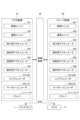
- 1 is a schematic diagram showing the configuration of an information presentation system 1 that performs information presentation processing after an operator manually inserts a catheter of a slave device 20.
- FIG. 1 is a schematic diagram showing the overall configuration of an information presentation system 1 according to one embodiment of the present invention.
- an information presentation system 1 according to this embodiment is configured as a master/slave system including a master device 10 and a slave device 20 that are mechanically separated.
- the master device 10 constitutes a manipulator operated by an operator
- the slave device 20 constitutes a catheter system having an end effector inserted into a subject. do.
- the information presentation system 1 includes a master device 10, a slave device 20, and an information presentation device 30.
- the master device 10, the slave device 20, and the information presentation device 30 are connected to a network 40. It is configured to enable wired or wireless communication via.
- the information presentation system 1 can include a display L and a plurality of cameras C as appropriate.
- the camera C various cameras such as a video camera that captures the appearance of the subject into which the slave device 20 is inserted, or an X-ray camera that captures the interior of the subject (for example, blood vessels and organs of the subject) by X-rays.
- a camera can be used.
- a plurality of displays L for displaying various images captured by a plurality of cameras C and various information output from the information presentation device 30 can be provided.
- the master device 10 receives an operation similar to that for a conventional mechanically configured catheter, and detects the position of a movable part (such as a movable member of a manipulator) that moves according to the input operation.
- the master device 10 transmits information representing the detected position of the movable part to the information presentation device 30 .
- the master device 10 outputs a reaction force with the actuator according to the instruction of the information presentation device 30 in response to the input operation.
- the master device 10 performs an operation to move the catheter forward and backward (for example, an operation to insert the catheter into a blood vessel or an operation to slightly move the catheter to detect haptic sensations near the lesion), and rotate the catheter around its axis.
- Manipulation e.g., changing the direction of the end effector
- manipulating the end effector e.g., if the end effector is a balloon, expanding or contracting it, or if the end effector is forceps, etc.
- opening and closing operations, etc. applies a reaction force to these operations, and transmits to the information presentation device 30 information representing the position of the movable portion moved by each operation.
- the slave device 20 drives an actuator according to instructions from the information presentation device 30 to perform an action corresponding to the operation input to the master device 10. Detects the position of a catheter, etc.). As the slave device 20 operates, various external forces are input to the slave device 20 from the environment. As a result, the position of the movable portion in the slave device 20 indicates the result of various external forces acting on the output of the actuator. The slave device 20 then transmits information representing the detected position of the movable portion to the information presentation device 30 .
- the various external forces that are input to the slave device 20 from the environment include, for example, a resistance force in the thrust direction that a catheter inserted into the subject receives from a blood vessel, a guide wire and an end effector that are placed at the tip of the catheter, and the like. This includes the contact force when the body comes into contact with a lesion, organ, or blood vessel.
- the information presentation device 30 is composed of, for example, an information processing device such as a PC (Personal Computer) or a server computer, and controls the master device 10, the slave device 20, the display L and the camera C.
- the information presentation device 30 acquires the positions of the movable parts of the master device 10 and the slave device 20 (such as the rotation angle of the actuator detected by a rotary encoder or the forward/backward position of the movable part detected by a linear encoder), Execute control for transmitting haptic sensations between the device 10 and the slave device 20 .
- the information presentation device 30 uses information representing the position of the movable part (the position of the movable element of the actuator or the member moved by the actuator).
- the parameters (input vector) in the real space calculated based on the information representing the position, etc.) are coordinate-transformed (transformed by a transformation matrix) into a virtual space in which position and force can be handled independently. That is, the input vector is coordinate-transformed from the real space of the oblique coordinate system in which the position and the force are related to each other to the virtual space of the orthogonal coordinate system in which the position and the force are mutually independent.
- the parameters calculated by the coordinate transformation represent the position and force state values corresponding to the input vector in the virtual space.
- the information presentation device 30 uses the position and force state values calculated from the input vector as position and force values for performing position and force control (here, haptic transmission). Calculations are performed to follow each target value, and inverse transformation (transformation using an inverse matrix of the transformation matrix) is performed to return the computation results to the real space. Further, the information presentation device 30 drives each actuator based on the real space parameters (current command value, etc.) obtained by the inverse transformation, thereby generating a haptic sensation between the master device 10 and the slave device 20. Realize a master-slave system for transmission.
- position and velocity (or acceleration) or angle and angular velocity (or angular acceleration) are parameters that can be replaced by calculus, so when performing processing related to position or angle, replace them with velocity or angular velocity as appropriate. is possible.
- the information presentation system 1 of the present embodiment realizes a master-slave system that transmits haptic sensations between the master device 10 and the slave device 20 as described above, and performs information presentation processing.
- the information presentation process is based on the external force input to the slave device 20 from the environment when the haptic sensation is transmitted to perform a predetermined action, and the physical characteristics of the substance with which the slave device 20 is in contact. is a series of processes for presenting
- the information presentation system 1 controls transmission of haptic sensations in the master device 10 and the slave device 20 .
- the information presentation system 1 calculates the physical properties of the substance with which the slave device 20 is in contact based on the external force input to the slave device 20 from the environment while the slave device 20 maintains a predetermined motion state. Calculate Furthermore, the information presentation system 1 presents the calculated physical properties of the substance.
- the information presentation system 1 under a quantitative state in which the slave device 20 maintains a predetermined state of motion, moves the slave device 20 forward based on an external force input from the environment to the slave device 20. It can present the physical properties of the material with which 20 comes into contact. Therefore, for example, the physical characteristics of a substance such as a blood vessel that cannot be directly touched by the operator are quantitatively presented as information obtained by the slave device 20 coming into contact with the substance (that is, tactile information). It is possible to further support the operation of the operator. In addition to the operation of the operator, the presented physical characteristics can be used to provide further support to those who perform various analyzes, inspections, and the like. Therefore, according to the information presentation system 1, it is possible to solve the problem of providing further support in addition to the support by transmitting the haptic sensation.
- FIG. 2 is a schematic diagram showing the basic principle of the haptic transmission control executed by the information presentation device 30.
- the basic principle shown in FIG. 2 determines the operation of the actuator by inputting information representing the position of the movable part (current position of the movable part) and performing calculations in at least one of the areas of velocity and force. be. That is, the basic principle of the present invention includes a system to be controlled S, a functional force/velocity assignment transformation block FT, at least one of an ideal force source block FC or an ideal velocity source block PC, and an inverse transformation block IFT. It is expressed as a control law.
- the controlled system S is the master device 10 or the slave device 20 equipped with an actuator, and controls the actuator based on acceleration and the like.
- acceleration, velocity, and position are physical quantities that can be mutually converted by calculus, any of acceleration, velocity, and position may be used for control.
- the control law is mainly expressed using the velocity calculated from the position.
- the function-specific force/velocity allocation conversion block FT is a block that defines the conversion of control energy into the velocity and force regions set according to the function of the controlled system S.
- a coordinate transformation is defined in which a value (reference value) serving as a reference for the function of the controlled system S and the current position of the movable part are input.
- This coordinate transformation generally converts an input vector whose elements are the reference value and the current velocity into an output vector composed of velocities for calculating the velocity control target value, and an input vector whose elements are the reference value and the current force. It converts the vector into an output vector consisting of force for calculating the force control target value.
- the coordinate transformation in the functional force/velocity allocation transformation block FT is generalized as shown in the following equations (1) and (2).
- x' 1 to x' n are velocity vectors for deriving the state value of velocity
- x' a to x' m are 1 or more
- ) is a vector whose elements are the reference value and the speed based on the action of the actuator (the speed of the mover of the actuator or the speed of the member moved by the actuator)
- h 1a to h nm are the elements of the conversion matrix representing the function. be.
- f′′ 1 to f′′ n are force vectors for deriving force state values
- f′′ a to f′′ m is an integer equal to or greater than 1
- f′′ a to f′′ m is an integer equal to or greater than 1 is a vector whose elements are the force based on the reference value and the action of the actuator (the force of the mover of the actuator or the force of the member moved by the actuator).
- the ideal force source block FC is a block that performs calculations in the force domain according to the coordinate transformation defined by the functional force/velocity assignment transformation block FT.
- a target value is set for the force when performing calculations based on the coordinate transformation defined by the functional force/velocity assignment transformation block FT.
- This target value is set as a fixed value or a variable value depending on the function to be implemented. For example, when realizing a function similar to the function indicated by the reference value, set the target value to zero, or when performing scaling, set a value obtained by expanding or reducing the information indicating the function to be realized. can.
- the ideal velocity source block PC is a block that performs calculations in the velocity domain according to the coordinate transformation defined by the functional force/velocity assignment transformation block FT.
- the ideal velocity source block PC there are set target values relating to velocity when performing calculations based on the coordinate transformation defined by the functional force/velocity assignment transformation block FT.
- This target value is set as a fixed value or a variable value depending on the function to be implemented. For example, when realizing a function similar to the function indicated by the reference value, set the target value to zero, or when performing scaling, set a value obtained by expanding or reducing the information indicating the function to be realized. can.
- the inverse transform block IFT is a block that transforms values in the domain of velocity and force into values in the domain of inputs to the controlled system S (for example, voltage values or current values).
- the functional force/velocity assignment conversion block FT when the positional information of the actuators of the controlled system S is input to the functional force/velocity assignment conversion block FT, the velocity and force information obtained based on the positional information is used to , in the function-specific force/velocity assignment conversion block FT, the control law for each of the position and force regions according to the function is applied.
- the ideal force source block FC force calculation is performed according to the function
- the ideal velocity source block PC velocity calculation is performed according to the function, and control energy is distributed to force and velocity respectively.
- the calculation results in the ideal force source block FC and the ideal velocity source block PC become information indicating the control target of the controlled system S, and these calculation results are used as input values for the actuators in the inverse transformation block IFT, and the controlled system S is entered in As a result, the actuators of the controlled system S perform operations according to the functions defined by the functional force/velocity assignment conversion block FT, and the intended operation of the device is realized.
- x'p is the velocity for deriving the state value of velocity
- x'f is the velocity related to the state value of force
- x'm is the speed of the reference value (input from the master device 10) (differential value of the current position of the master device 10)
- x 's is the current speed of the slave device 20 (differential value of the current position).
- f p is the force related to the state value of velocity
- f f is the force for deriving the state value of force
- f m is the force of the reference value (input from the master device 10 )
- f s is the current force of the slave device 20 .
- the position of the slave device 20 is multiplied by ⁇ ( ⁇ is a positive number)
- the force of the slave device 20 is multiplied by ⁇ ( ⁇ is a positive number)
- the master It will be transmitted to the device 10 .
- the haptic sensation is transmitted without being amplified (that is, expanded) or attenuated (that is, reduced).
- scaling to amplify (that is, expand) or attenuate (that is, reduce) the haptic sensation to be transmitted can be performed. Realization is possible.
- FIG. 3 is a block diagram showing the hardware configuration of the control system in the information presentation system 1.
- the information presentation system 1 includes an information presentation device 30 configured by an information processing device such as a PC or a server computer as a hardware configuration of a control system, and a control unit 101 of the master device 10.
- control unit 201 control unit 201, communication unit 202, insertion actuator 203, detection actuator 204, rotation actuator 205, operation actuator 206, linear encoders 207 and 208, rotary encoders 209 and 210, Drivers 211 to 214, a display L, and a camera C are provided.
- a control unit 101 of the master device 10 is composed of a microcomputer including a processor, memory, etc., and controls the operation of the master device 10 .
- the control unit 101 controls driving of the insertion actuator 103 , the detection actuator 104 , the rotation actuator 105 and the operation actuator 106 of the master device 10 according to control parameters transmitted from the information presentation device 30 .
- Communication unit 102 controls communication between master device 10 and other devices via network 40 .
- the insertion actuator 103 is composed of, for example, a direct-acting motor, and according to instructions from the control unit 101, the operator inputs the operation to the master device 10 to move the catheter forward and backward in order to insert it into the blood vessel. Gives a reaction force.
- the detection actuator 104 is composed of, for example, a voice coil motor, and applies a reaction force to an operator's input to the master device 10 in accordance with instructions from the control unit 101 to advance and retract the catheter near the lesion for treatment. Give.
- the insertion actuator 103 has a longer stroke than the detection actuator 104, while the detection actuator 104 performs more precise position and force control than the insertion actuator 103. It is possible.
- the rotation actuator 105 is composed of, for example, a rotary motor, and applies a reaction force to the operator's operation to rotate the master device 10 around the rotation axis along the advancing/retreating direction according to instructions from the control unit 101 .
- the operation actuator 106 is configured by, for example, a rotary motor, and applies a reaction force to an operation input by the operator to a lever (grip) or the like for operating the end effector, according to instructions from the control unit 101. .
- the linear encoder 107 detects the position of the mover of the insertion actuator 103 (advance/retreat position on the linear motion axis).
- the linear encoder 108 detects the position of the mover of the detection actuator 104 (advance/retreat position on the linear motion axis).
- a rotary encoder 109 detects the position (rotational angle) of the mover of the rotary actuator 105 .
- the rotary encoder 110 detects the position (rotational angle) of the mover of the operating actuator 106 .
- the driver 111 outputs drive current to the insertion actuator 103 according to instructions from the control unit 101 .
- the driver 112 outputs a drive current to the detection actuator 104 according to instructions from the control unit 101 .
- the driver 113 outputs drive current to the rotation actuator 105 according to the instruction from the control unit 101 .
- the driver 114 outputs drive current to the operating actuator 106 in accordance with instructions from the control unit 101 .
- a control unit 201 of the slave device 20 is configured by a microcomputer having a processor, memory, etc., and controls the operation of the slave device 20 .
- the control unit 201 controls the driving of the insertion actuator 203 , the detection actuator 204 , the rotation actuator 205 and the manipulation actuator 206 of the slave device 20 according to control parameters transmitted from the information presentation device 30 .
- the communication unit 202 controls communication between the slave device 20 and other devices via the network 40 .
- the insertion actuator 203 is composed of, for example, a direct-acting motor, and according to instructions from the control unit 201, the operator inputs the operation to the master device 10 to move the catheter forward and backward in order to insert it into the blood vessel.
- the catheter of the slave device 20 is advanced and retracted.
- the detection actuator 204 is composed of, for example, a voice coil motor, and according to instructions from the control unit 201, the slave device 20 responds to an operation input by the operator to the master device 10 to advance and retract the catheter near the lesion for treatment. advance and retract the catheter.
- the insertion actuator 203 has a longer stroke than the detection actuator 204, while the detection actuator 204 performs more precise position and force control than the insertion actuator 203. It is possible.
- the rotation actuator 205 is configured by, for example, a rotary motor, and rotates the catheter of the slave device 20 around a rotation axis along the advancing/retreating direction in accordance with instructions from the control unit 201 and in accordance with operations input to the master device 10 by the operator.
- the operation actuator 206 is composed of, for example, a rotary motor, and operates the end effector (expansion, contraction, opening/closing, etc.) according to the operation input to the master device 10 by the operator according to instructions from the control unit 201. .
- the linear encoder 207 detects the position of the mover of the insertion actuator 203 (advance/retreat position on the linear motion axis).
- a linear encoder 208 detects the position of the mover of the detection actuator 204 (advance/retreat position on the linear motion axis).
- a rotary encoder 209 detects the position (rotational angle) of the mover of the rotary actuator 205 .
- a rotary encoder 210 detects the position (rotational angle) of the mover of the operating actuator 206 .
- the driver 211 outputs drive current to the insertion actuator 203 according to instructions from the control unit 201 .
- the driver 212 outputs a drive current to the detection actuator 204 according to instructions from the control unit 201 .
- the driver 213 outputs a drive current to the rotation actuator 205 according to instructions from the control unit 201 .
- a driver 214 outputs a drive current to the operation actuator 206 according to an instruction from the control unit 201 .
- the display L is installed in a place where the operator of the master device 10 can visually recognize the screen, and an image instructed to be displayed by the information presentation device 30 (visible light image, X-ray image, etc. of the subject captured by the camera C). Alternatively, information instructed to be displayed by the information presentation device 30 is displayed.
- the camera C is installed in a place where the slave device 20 can capture an image of the subject into which the catheter is to be inserted. Send.
- FIG. 4 is a schematic diagram showing a hardware configuration of an information processing device that constitutes the information presentation device 30.
- the information presentation device 30 includes a processor (Central Processing Unit) 311, a ROM (Read Only Memory) 312, a RAM (Random Access Memory) 313, a bus 314, an input section 315, and an output A unit 316 , a storage unit 317 , a communication unit 318 and a drive 319 are provided.
- a processor Central Processing Unit
- ROM Read Only Memory
- RAM Random Access Memory
- the processor 311 executes various processes according to programs recorded in the ROM 312 or programs loaded from the storage unit 317 to the RAM 313 .
- the RAM 313 also stores data necessary for the processor 311 to execute various types of processing.
- the processor 311 , ROM 312 and RAM 313 are interconnected via a bus 314 .
- An input unit 315 , an output unit 316 , a storage unit 317 , a communication unit 318 and a drive 319 are connected to the bus 314 .
- the input unit 315 is composed of various buttons and the like, and inputs various information according to instruction operations.
- the output unit 316 includes a display, a speaker, and the like, and outputs images and sounds.
- the display of the input unit 315 and the display of the output unit 316 may be overlapped to configure a touch panel.
- the storage unit 317 is composed of a hard disk, a DRAM (Dynamic Random Access Memory), or the like, and stores various data managed by each server.
- the communication unit 318 controls communication between the information presentation device 30 and other devices via the network.
- a removable medium 331 consisting of a magnetic disk, an optical disk, a magneto-optical disk, a semiconductor memory, or the like is appropriately mounted in the drive 319 .
- a program read from the removable medium 331 by the drive 319 is installed in the storage unit 317 as required.
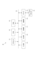
- FIG. 5 is a block diagram showing the functional configuration of the information presentation system 1.
- the information presentation device 30 executes various types of processing to cause the CPU 311 to perform a sensor information acquisition unit 351, a tactile sense transmission unit 352, a distance information acquisition unit 353, A mode setting unit 354, a calculation unit 355, and a presentation unit 356 function. Further, a control parameter storage unit 371 and a physical property storage unit 372 are formed in the storage unit 317 .
- the control parameter storage unit 371 stores control parameters acquired in the control of the information presentation device 30 transmitting haptic sensations between the master device 10 and the slave device 20 in chronological order.
- the information stored as the control parameters can be various parameters acquired in haptic transmission control, and can include various types of information that can reproduce the haptic transmission control.
- sensor information acquired by the master device 10 and the slave device 20 state values obtained by coordinate transformation of these sensor information, current command values to each actuator, or information set in the information presentation device 30 for tactile transmission control. It is possible to store various setting values and the like as control parameters.
- the physical property storage unit 372 stores the physical property of the substance with which the slave device 20 has come into contact, which is calculated by the calculation unit 355 .
- the calculator 355 calculates “elasticity”, “viscosity” and “inertia” as the physical properties of the substance. Therefore, the physical property storage unit 372 stores each of these "elasticity", “viscosity” and “inertia”.
- the presentation unit 356 presents the physical properties of the substance calculated by the calculation unit 355 and the physical properties of the reference substance so that they can be compared. Therefore, the physical property storage unit 372 also stores the physical property of this reference substance.
- the physical properties of the reference substance may be physical properties calculated by the calculation unit 355 in the past, or physical properties measured by an inspection method or a tactile method different from the calculation by the calculation unit 355. may be
- the sensor information acquisition unit 351 acquires sensor information detected by various sensors installed in the master device 10 and slave devices 20 .
- the sensor information acquisition unit 351 acquires information indicating the position (forward/backward position or rotation angle) of the mover of each actuator detected by the linear encoders 107, 108, 207, 208 and the rotary encoders 109, 110, 209, 210. get.
- the sensor information acquisition unit 351 also stores the acquired sensor information in the control parameter storage unit 371 as time-series data.
- the haptic transmission unit 352 controls haptic transmission in the master device 10 and the slave device 20 according to the control algorithm shown in FIG. For example, the haptic transmission unit 352 executes control to transmit haptic sensations between actuators for corresponding operations of the master device 10 and the slave device 20 in the information presentation process.
- the distance information acquisition unit 353 acquires distance information, which is information indicating the distance between the tip of the catheter and the lesion, by performing calculations, analysis, etc. on various data. Further, distance information acquisition section 353 outputs the acquired distance information to mode setting section 354 . This distance information is used in mode setting section 354 to determine whether or not to switch modes.
- the distance information acquisition unit 353 acquires distance information using the image captured by the camera C.
- the distance information acquiring unit 353 acquires distance information by analyzing this image and calculating the distance between the tip of the catheter and the lesion.
- the distance information acquisition unit 353 may acquire distance information using various sensors.
- a magnetic detection marker is provided at the tip of the catheter, the position of the tip of the catheter is detected from the outside of the subject by a magnetic sensor, and distance information is obtained by calculating the distance to the lesion.
- the distance information acquisition unit 353 may install a sensor inside the subject in advance to detect the position of the tip of the catheter, detect the position of the catheter with this sensor, and calculate the distance to the lesion. , the distance information may be obtained.
- the distance information acquisition section 353 outputs the distance information thus acquired to the mode setting section 354 .
- the mode setting unit 354 switches and sets the three modes of “insertion mode”, “detection mode”, and “measurement mode” as modes to be set in the information presentation device 30 . Specifically, the mode setting unit 354 selects the “insertion mode” when the tip of the catheter has not reached the vicinity of the lesion based on the distance between the tip of the catheter and the lesion acquired as the distance information by the distance information acquiring unit 353. , and when it reaches the vicinity of the lesion, it switches to "detection mode".
- the criterion for switching the mode when the distance approaches is, for example, the subject or the subject simulated in the past It can be set based on an actual measurement value, a statistical value, an estimated value obtained by simulation, or the like when a catheter is inserted into a biological model.
- the mode setting unit 354 performs the mode switching operation via the input unit 315 by the operator or the mode switching operation by communication from an external device (for example, the master device 10) via the communication unit 318. Switch between detection mode and measurement mode. That is, the operator can switch between the "detection mode” and the “measurement mode” at any desired timing.
- the "insertion mode” is a mode in which the insertion actuator 203 is used to move the catheter forward and backward in the slave device 20, and haptic sensation is transmitted to and from the insertion actuator 103 of the master device 10.
- the "insertion mode” is, for example, a mode that is set until the tip of the catheter reaches the vicinity of the lesion after the operator inserts the catheter into the subject.
- the “sensing mode” is a mode in which the sensing actuator 204 is used to move the catheter forward and backward in the slave device 20, and haptic sensation is transmitted to and from the sensing actuator 104 of the master device 10.
- the “detection mode” is, for example, a mode that is set after the operator inserts a catheter into the subject and the tip of the catheter reaches the vicinity of the lesion.
- the “measurement mode” is a mode in which the sensing actuator 204 is used to move the catheter forward and backward in the slave device 20, and the physical properties of the substance with which the catheter comes into contact are calculated and presented.
- the master device 10 does not accept any operation by the operator.
- the slave device 20 does not perform an operation corresponding to the operation on the master device 10 , but follows an instruction for realizing a predetermined motion state generated by the haptic transmission unit 352 . By driving the actuator 204, an operation is performed so as to maintain a predetermined motion state.
- the “measurement mode” is, for example, a mode set to present the physical properties of substances in lesions to an operator or the like.
- the insertion actuators 103 and 203 have longer strokes than the detection actuators 104 and 204, while the detection actuators 104 and 204 have longer strokes than the insertion actuators 103 and 203. It is possible to control the position and force with higher accuracy than in the conventional method. Therefore, the "sensing mode" is used in situations where the operator needs to sense a minute external force input to the slave device 20, as opposed to the "insertion mode”. Also, the “measurement mode” is used in a state where it is necessary to accurately calculate the physical properties of the substance in the lesion based on the minute external force input to the slave device 20 .
- the calculation unit 355 calculates the physical properties of the substance with which the slave device 20 is in contact (here, the substance in the lesion with which the tip of the catheter is in contact).
- the haptic transmission unit 352 In order to calculate the physical properties of this substance, in the "measurement mode", the haptic transmission unit 352 generates instructions for realizing a predetermined state of motion.
- the slave device 20 drives the detection actuator 204 in accordance with the instruction for realizing the predetermined motion state generated by the haptic transmission unit 352, thereby maintaining the predetermined motion state. conduct.
- the calculation unit 355 calculates values indicating various external forces (hereinafter referred to as “force (referred to as “the value of This force value can be calculated as the product of mass and acceleration. Therefore, the distance information acquisition unit 353 stores the sensor information acquired by the sensor information acquisition unit 351, which is stored as control parameters by the control parameter storage unit 371, and the functional force/velocity allocation conversion block FT in the control algorithm shown in FIG. Based on the information corresponding to the result of coordinate transformation to be performed, a force value is obtained by performing an operation such as integration in real time. In this case, the distance information acquisition unit 353 may acquire the force value after performing filtering using a band-limiting filter on the waveform of the instantaneous value. Thus, the calculator 355 can calculate the force value based on the control parameters. Therefore, in this embodiment, it is not necessary to provide a force sensor to measure the force value.
- the calculator 355 calculates elasticity, viscosity, and inertia as the physical properties of the substance. A method of calculating each of these physical properties by the calculating unit 355 and the control by the haptic sensation transmitting unit 352 performed therefor will be described below.
- the predetermined motion state is a state in which the catheter is inserted by uniform motion. Therefore, the haptic transmission unit 352 differentiates in real time the position (or angle) of the movable part (such as the mover of the actuator or the catheter moved by the actuator) that is moved by the operation of the slave device 20 and is acquired as sensor information. By doing so, the velocity (or angular velocity) is calculated. Then, the haptic transmission unit 352 controls the operation of the slave device 20 so that the calculated velocity (or angular velocity) becomes a constant value. In addition, the haptic transmission section 352 continues this control until the movable section moved by the operation of the slave device 20 moves a predetermined movement distance ( ⁇ x).
- ⁇ x predetermined movement distance
- the calculation unit 355 calculates the force change amount ( ⁇ F) by subtracting the force value at the start of the uniform motion from the force value at the end of the uniform motion. Then, the calculation unit 355 divides the force change amount ( ⁇ F) by the moving distance ( ⁇ x) while the uniform motion is maintained, and calculates the value of the substance with which the slave device 20 is in contact (here, the catheter). It is calculated as a value that indicates the elasticity (equivalent to the spring constant) of the material in the lesion that the tip touches.
- the predetermined motion state is a state in which the catheter is inserted by uniformly accelerating motion. Therefore, the haptic transmission unit 352 calculates velocity (or angular velocity) in the same manner as when calculating elasticity. Then, the haptic transmission unit 352 calculates acceleration (or angular acceleration) by further differentiating the calculated velocity (or angular velocity). Then, the haptic transmission unit 352 controls the operation of the slave device 20 so that the calculated acceleration (or angular acceleration) becomes a constant value. In addition, the haptic transmission section 352 continues this control until the movable section moved by the operation of the slave device 20 moves a predetermined movement distance ( ⁇ x).
- the calculation unit 355 calculates the force change amount ( ⁇ F) by subtracting the force value at the start of the uniformly accelerated motion from the force value at the end of the uniformly accelerated motion. Then, the calculation unit 355 divides the force change amount ( ⁇ F) by the moving distance ( ⁇ x) while the constant acceleration motion is maintained, and calculates the value of the substance (here, the catheter) with which the slave device 20 is in contact. It is calculated as a value that indicates the viscosity of the substance in the lesion that the tip touches.
- the predetermined motion state is a state in which the insertion of the catheter is performed by uniform jerk motion (also referred to as uniform jerk motion). Therefore, the haptic transmission unit 352 calculates the acceleration (or the acceleration) in the same manner as when calculating the viscosity. Then, the haptic transmission unit 352 calculates the jerk (or angular jerk) by further differentiating the calculated acceleration (or angular acceleration). Then, the haptic transmission unit 352 controls the operation of the slave device 20 so that the calculated jerk (or angular jerk) becomes a constant value.
- the haptic transmission section 352 continues this control until the movable section moved by the operation of the slave device 20 moves a predetermined movement distance ( ⁇ x). As a result, uniform jerk motion, which is a predetermined motion state, is maintained.
- the calculation unit 355 calculates the force change amount ( ⁇ F) by subtracting the force value at the start of the uniform jerk motion from the force value at the end of the uniform jerk motion. .
- the calculation unit 355 divides the force change amount ( ⁇ F) by the movement distance ( ⁇ x) while the constant jerk motion is maintained, and calculates the value of the substance with which the slave device 20 is in contact (here, a catheter It is calculated as a value that indicates the inertia of the substance in the lesion that the tip of
- the elasticity, viscosity, and inertia calculated by the calculation unit 355 based on the force values under a quantitative state in which the slave device 20 maintains a predetermined state of motion are used as physical properties. It is stored in the storage unit 372 . Note that the calculation unit 355 does not necessarily need to calculate all of these elasticity, viscosity, and inertia, and may calculate at least one of them.
- the presentation unit 356 presents the physical properties such as elasticity, viscosity, and inertia calculated by the calculation unit 355 to the operator and those who perform various analyzes and inspections.
- the presentation can be realized by displaying on the display L, for example, numerical values, graphs, or the like indicating physical properties and force values. Alternatively, the presentation can also be realized by outputting numerical values and the like by voice from a speaker included in the output unit 316 .
- the timing of the presentation by the presentation unit 356 is, for example, in real time at the same time that the calculation unit 355 calculates the physical characteristics in the "measurement mode". Also, after that, the presentation may be continued even when the "detection mode" or the "insertion mode” is switched again. Alternatively, after the information presentation process is completed, presentation may be performed in order to perform various analyses, inspections, and the like.
- the presentation unit 356 may present the physical properties of the substance calculated by the calculation unit 355 and the physical properties of the reference substance so that they can be compared.
- the physical property storage unit 372 stores the physical property that serves as a reference.
- the physical properties of the reference substance may be physical properties calculated by the calculation unit 355 in the past, or physical properties measured by an inspection method or a tactile method different from the calculation by the calculation unit 355. may be
- the physical properties of the reference material are, for example, standard values such as elasticity of the lesion when the lesion is calcified. The operator or the like compares the standard value of the lesion in such a specific state with the value calculated by the presentation unit 356 to obtain information about the state of the lesion (here, the degree of calcification). can grasp.
- the operator can grasp the condition of the lesion using objective indicators such as numerical values. That is, it is possible to grasp both the subjective index of transmitted haptic sensation and the objective index. As a result, in addition to the support by transmitting the haptic sensation, further support can be provided.
- FIG. 6 is a flowchart for explaining the flow of information presentation processing executed by the information presentation device 30.
- an instruction to execute the information presentation process is given by the operator via the input unit 315, or an instruction to execute the information presentation process is given by communication from an external device (for example, the master device 10) via the communication unit 318. Initiated in response to what is done.
- an assistant who assists the operation of the slave device 20 manually or remotely operates the master device 10 so that the tip of the catheter is moved to the subject by a predetermined distance. Assume that it starts in an inserted state (for example, a state in which it is inserted by about 1 to 10 [cm]). As a result, it is possible to prevent the control of the information presentation device 30 from becoming unstable in a state where the change in the external force at the initial stage of insertion is large.
- step S11 the mode setting unit 354 sets the insertion mode.
- step S ⁇ b>12 the sensor information acquisition unit 351 starts acquiring sensor information detected by various sensors installed in the master device 10 and the slave device 20 . Acquisition of this sensor information is performed in parallel with other steps until this process ends. Further, the acquired sensor information is stored in the control parameter storage unit 371 as time-series data.
- step S13 the haptic transmission unit 352 starts controlling haptic transmission based on the sensor information. This haptic transmission control is performed in parallel with other steps until this process ends.
- step S14 the distance information acquisition unit 353 acquires distance information by performing calculations, analysis, etc. on various data. Further, distance information acquisition section 353 outputs the acquired distance information to mode setting section 354 .
- step S15 the mode setting unit 354 determines whether or not to switch the mode based on the distance information and the mode switching operation by the operator. That is, based on the distance between the tip of the catheter and the lesion indicated by the distance information, whether to switch between the "insertion mode” and the "detection mode", and whether or not the operator performs a mode switching operation, the "detection mode" is determined. A determination is made as to whether or not to switch between "mode” and "measurement mode". When switching to any mode, it is determined as Yes in step S15, and the process proceeds to step S16. On the other hand, if the mode is not to be switched, it is determined as No in step S15, and the process proceeds to step S17.
- step S16 the mode setting unit 354 switches modes. That is, the mode is switched to any one of "insertion mode”, “detection mode”, and “measurement mode” according to the determination result of step S15.
- step S17 the calculation unit 355 determines whether the currently set mode is the "insertion mode", the "detection mode", or the "measurement mode". If it is “insertion mode” or “detection mode”, it is determined in step S17 that it is “detection mode, insertion mode”, and the process proceeds to step S23. On the other hand, if it is the "measurement mode”, it is determined to be the "measurement mode” in step S17, and the process proceeds to step S18.
- step S18 the calculator 355 starts calculating the force value.
- step S19 the haptic transmission section 352 starts controlling the operation of the slave device 20 so as to achieve a predetermined motion state.
- step S20 the haptic transmission section 352 determines whether or not the movable section moved by the operation of the slave device 20 has moved a predetermined movement distance ( ⁇ x). If the predetermined moving distance ( ⁇ x) has been moved, it is determined as Yes in step S20, and the process proceeds to step S21. On the other hand, if the predetermined moving distance ( ⁇ x) has not been moved, it is determined as No in step S20, and the process returns to step S18 and repeats.
- step S21 the calculator 355 calculates the physical properties of the substance (here, the substance in the lesion contacted by the tip of the catheter).
- step S22 the presentation unit 356 starts presenting the physical characteristics calculated in step S21.
- steps S18 to S22 are repeated multiple times.
- a physical property e.g., elasticity
- changes in the calculated value may be presented in the form of a graph, or elasticity, viscosity, and inertia may be calculated in turn. may be presented.
- step S23 the haptic transmission unit 352 determines whether or not the termination condition for terminating this process is satisfied.
- the end condition is, for example, an instruction to end the information presentation process by an operator via the input unit 315 or an instruction to end the information presentation process by communication from an external device (for example, the master device 10) via the communication unit 318. is to be done. If the end condition is satisfied, a determination of Yes is made in step S23, and this process ends. On the other hand, if the termination condition is not satisfied, a determination of No is made in step S23, and the process returns to step S14 and is repeated.
- the slave device 20 Under the quantitative state that the slave device 20 maintains a predetermined motion state, the slave device It can present the physical properties of the material with which 20 comes into contact. Therefore, for example, the physical characteristics of a substance such as a blood vessel that cannot be directly touched by the operator are quantitatively presented as information obtained by the slave device 20 coming into contact with the substance (that is, tactile information). It is possible to further support the operation of the operator. In addition to the operation of the operator, the presented physical characteristics can be used to provide further support to those who perform various analyzes, inspections, and the like. Therefore, according to the information presentation process, it is possible to solve the problem of providing further support in addition to the support by transmitting the haptic sensation.
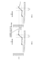
- FIG. 7 is a schematic diagram showing time-series changes in the external force input from the environment to the slave device 20 when the slave device 20 comes into contact with a substance in the above-described embodiment.
- FIG. 7A is a schematic diagram of a case where the slave device 20 contacts the acrylic wall as the first contact target.
- FIG. 7B is a schematic diagram of a case where the slave device 20 comes into contact with an arteriosclerotic blood vessel as a second contact target.
- the horizontal axis represents time [S]
- the vertical axis represents the force value [N] indicating the magnitude of the external force input to the slave device 20.
- a comparison period P1 is defined as a period from when the force value begins to increase steeply until the force value reaches a certain level.
- a comparison period P2 is defined as a period from when the force value begins to increase sharply until the same length of time as the comparison period P1 elapses.
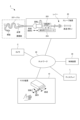
- FIG. 8 is a schematic diagram showing the configuration of the information presentation system 1 that performs information presentation processing after the operator manually inserts the catheter of the slave device 20.
- the catheter of the slave device 20 is provided with an operating lever (grasping portion) or the like, and can be manually operated by the operator.
- the information presentation system 1 of this modified example includes only the detection actuators 104 and 204 among the linear motion actuators included in the information presentation system 1 of the first embodiment shown in FIG. is not prepared.
- slave device 20 When the operator manually inserts the catheter, in slave device 20 the catheter is released from movement control by sensing actuator 204 and rotation actuator 205 and can be manipulated like a conventional catheter. At this time, it is assumed that the operator inserts the catheter to a position in front of the vicinity of the lesion, and information presentation processing is started with this state as the initial state.
- the catheter is held for movement control by the detection actuator 204 and the rotation actuator 205, and the slave device 20 moves the catheter according to the operation of the master device 10, and the information is presented. Control for transmitting the haptic sensation by the device 30 is started. Then, in the same manner as in the case of setting the "detection mode" in the above-described embodiment, the actuator is operated, and information presentation processing is performed to enable switching to the "measurement mode". Physical properties of the material calculated based on the values can be presented. According to this modified example, since the distance over which the catheter is moved by the actuator is relatively short, it is sufficient to have an actuator with a short stroke such as a voice coil motor. can do.
- the force in the thrust direction (advancing and retreating direction) of the catheter is transmitted between the master device 10 and the slave device 20 by haptic sensation, but the present invention is not limited to this.
- haptic transmission may be performed between the master device 10 and the slave device 20 for rotation about a rotation axis along the advancing/retreating direction or for operating an end effector.
- the case where the information presentation system 1 remotely operates the catheter has been described as an example, but the present invention is not limited to this. That is, various devices can be targeted as the devices that are remotely operated by the information presentation system 1.
- various devices having a linearly configured portion such as forceps or an endoscopic device.
- a medical device such as a mirror can be targeted.
- the case where the actuators provided in the master device 10 and the actuators provided in the slave device 20 are associated one-to-one to transmit the haptic sensation has been described as an example.
- a plurality of actuators of the master device 10 are associated with one actuator of the slave device 20 to transmit a haptic sensation
- one actuator of the master device 10 is associated with a plurality of actuators of the slave device 20 to transmit haptic sensations. It is possible to communicate It is also possible to associate the plurality of actuators of the master device 10 with the plurality of actuators of the slave device 20 to transmit the haptic sensation.
- the insertion actuator 203 and the detection actuator 204 of the slave device 20 shown in FIG. 3 can be associated with the insertion actuator 103 of the master device 10 to transmit the haptic sensation.
- the configuration including the insertion actuator 203 and the detection actuator 204 as actuators for advancing and retracting the catheter of the slave device 20 has been described as an example, but the configuration is not limited to this. That is, the catheter of the slave device 20 may be advanced and retracted with a single actuator as long as the actuator satisfies the required performance in stroke and accuracy of operation.
- the process of switching between the insertion mode and the detection mode is omitted, and the actuator is operated in the same manner as in the case of setting the "detection mode" in the above-described embodiment, and the information presentation process is performed to switch to the "measurement mode".
- the actuator is operated in the same manner as in the case of setting the "detection mode" in the above-described embodiment, and the information presentation process is performed to switch to the "measurement mode".
- the mode setting unit 354 determines, based on the distance between the tip of the catheter and the lesion acquired as the distance information by the distance information acquisition unit 353, if the tip of the catheter has not reached the vicinity of the lesion.
- the mode is switched to the "insertion mode” and then switched to the "detection mode" when reaching the vicinity of the lesion
- the present invention is not limited to this.
- various external forces input from the environment change between, for example, a state in which the catheter is advanced through an artery and a state in which it reaches a lesion in a stenosed heart. , the value of the force also changes accordingly.
- the mode setting unit 354 calculates the force value in the same manner as the calculation unit 355, determines the insertion state of the catheter based on the force value, and switches between the "insertion mode” and the "detection mode”. .
- the mode setting unit 354 switches to the "insertion mode” when the force value is less than a predetermined value, and switches to the "detection mode” when the force value is greater than or equal to the predetermined value.
- the mode setting unit 354 performs mode switching operation by an operator via the input unit 315 or by communication from an external device (for example, the master device 10) via the communication unit 318.
- an external device for example, the master device 10.
- the mode setting unit 354 can set distance The “detection mode” and the “measurement mode” may be switched based on information or the like.
- the mode setting unit 354 determines that the distal end of the catheter is closer to the lesion based on the distance information after switching to the "detection mode"
- the mode setting unit 354 does not require a switching operation from the operator or the like. It is good also as switching to a "measurement mode.”
- the mode setting unit 354 switches to the "detection mode” without requiring a switching operation from the operator or the like. good.
- the information presentation system 1 includes the master device 10 to which the operator's operation is input, and the slave device 20 that operates according to the operation input to the master device 10 .
- the information presentation system 1 also includes a haptic transmission unit 352 , a calculation unit 355 , and a presentation unit 356 .
- the haptic transmission unit 352 controls haptic transmission between the master device 10 and the slave device 20 .
- the calculation unit 355 calculates the physical properties of the substance with which the slave device 20 is in contact, based on the external force input to the slave device 20 from the environment while the slave device 20 maintains a predetermined motion state.
- the presentation unit 356 presents the physical properties of the substance calculated by the calculation unit 355 .
- the information presentation system 1 under a quantitative state in which the slave device 20 maintains a predetermined state of motion, moves the slave device 20 forward based on an external force input from the environment to the slave device 20. It can present the physical properties of the material with which 20 comes into contact. Therefore, for example, the physical characteristics of a substance such as a blood vessel that cannot be directly touched by the operator are quantitatively presented as information obtained by the slave device 20 coming into contact with the substance (that is, tactile information). It is possible to further support the operation of the operator. In addition to the operation of the operator, the presented physical characteristics can be used to provide further support to those who perform various analyzes, inspections, and the like. Therefore, according to the information presentation system 1, it is possible to solve the problem of providing further support in addition to the support by transmitting the haptic sensation.
- the calculation unit 355 calculates elasticity as a physical property of a substance when the slave device 20 maintains a state of uniform motion as a predetermined motion state. This makes it possible to quantitatively present the elasticity of a substance such as a blood vessel that cannot be directly touched by the operator.
- the calculation unit 355 calculates the viscosity as the physical property of the substance when the slave device 20 maintains the state of constant acceleration motion as the predetermined operating state. This makes it possible to quantitatively present the viscosity of a substance such as a blood vessel that cannot be directly touched by the operator.
- the calculation unit 355 calculates inertia as a physical property of a substance when the slave device 20 maintains a uniform jerk motion state as a predetermined operating state. This makes it possible to quantitatively present the inertia of substances such as blood vessels that cannot be directly touched by the operator.
- the calculation unit 355 determines whether or not the slave device 20 has maintained the predetermined state of motion based on the movement distance of the slave device 20 since the predetermined state of motion was started. Accordingly, it is possible to determine whether or not a predetermined state of motion is maintained by using sensor information for controlling the transmission of the haptic sensation.
- the presentation unit 356 presents the physical properties of the substance calculated by the calculation unit 355 and the physical properties of the reference substance in a comparable manner. As a result, for example, it is possible to compare quantitative physical characteristics based on information (i.e., tactile information) obtained when the slave device 20 comes into contact with a substance with reference physical characteristics, Further assistance can be provided to the operator or the like.
- information i.e., tactile information
- the presentation unit 356 presents the physical properties of the substance calculated by the calculation unit 355 to the operator who is operating the master device 10 . As a result, real-time assistance can be provided to the operator during operation.
- the information presentation device 30 includes the haptic transmission unit 352 , the calculation unit 355 , and the presentation unit 356 .
- the haptic transmission unit 352 controls haptic transmission between the master device 10 to which the operator's operation is input and the slave device 20 that operates according to the operation input to the master device 10 .
- the calculation unit 355 calculates the physical properties of the substance with which the slave device 20 is in contact, based on the external force input to the slave device 20 from the environment while the slave device 20 maintains a predetermined motion state. .
- the presentation unit 356 presents the physical properties of the substance calculated by the calculation unit 355 . With such a configuration of the information presentation device 30, similarly to the information presentation system 1 described above, it is possible to solve the problem of providing further assistance in addition to the assistance by transmitting the haptic sensation.
- the present invention is not limited to the above-described embodiments, and includes modifications, improvements, and the like within the scope of achieving the object of the present invention.
- the present invention can be implemented as the information presentation system 1 in the above-described embodiment, an information presentation device for controlling the information presentation system 1, and an information presentation method configured by steps executed in the information presentation system 1.
- it can be implemented as a program executed by a processor to implement the functions of the information presentation system 1 .
- the configuration in which the information presentation device 30 is implemented as an independent device has been described as an example. 201 or distributed in both of them.
- the processing in the above-described embodiments can be executed by either hardware or software. That is, it is sufficient that the information presentation system 1 has a function capable of executing the above-described processing, and the functional configuration and hardware configuration for realizing this function are not limited to the above-described example.
- a program that constitutes the software is installed in the computer from a network or a storage medium.
- the storage medium that stores the program consists of a removable medium that is distributed separately from the device main body, or a storage medium that is pre-installed in the device main body.
- Removable media are composed of, for example, a semiconductor memory, a magnetic disk, an optical disk, or a magneto-optical disk.
- Optical discs are composed of, for example, CD-ROMs (Compact Disk-Read Only Memory), DVDs (Digital Versatile Disks), Blu-ray Discs (registered trademark), and the like.
- the magneto-optical disk is composed of an MD (Mini-Disk) or the like.
- the storage medium pre-installed in the device main body is composed of, for example, a ROM (Read Only Memory) storing programs, a hard disk, or a semiconductor memory.
- Information presentation system 10 Master device, 20 Slave device, 30 Information presentation device, 40 Network, L Display, C Camera, FT Functional force/velocity allocation conversion block, FC Ideal force source block, PC Ideal velocity (position) source Block, IFT Inverse transform block, S Controlled system, 101, 201 control unit, 102, 202 communication unit, 103, 203 insertion actuator, 104, 204 detection actuator, 105, 205 rotation actuator, 106, 206 operation Actuator, 107, 108, 207, 208 linear encoder, 109, 110, 209, 210 rotary encoder, 111 to 114, 211 to 214 driver, 311 processor, 312 ROM, 313 RAM, 314 bus, 315 input section, 316 output section , 317 storage unit, 318 communication unit, 319 drive, 331 removable media, 351 sensor information acquisition unit, 352 haptic transmission unit, 353 distance information acquisition unit, 354 mode setting unit, 355 calculation unit, 356 presentation unit, 371 control parameters Storage unit, 372
Abstract
The present invention addresses the problem of providing additional support on top of support based on haptic sense transmission. An information presenting system (1) according to the present invention comprises: a master device (10) to which an operation of an operator is input; and a slave device (20) operating in response to the operation input to the master device (10). The information presenting system (1) comprises a haptic sense transmission unit (352), a calculation unit (355), and a presentation unit (356). The haptic sense transmission unit (352) controls transmission of a haptic sense between the master device (10) and the slave device (20). The calculation unit (355) calculates a physical property of a substance with which the slave device (20) comes into contact, on the basis of the external force input from the environment to the slave device (20) during the period when the slave device (20) maintains a predetermined motion state. The presentation unit (356) presents the physical property of the substance calculated by the calculation unit (355).
Description
本発明は、情報提示システム、情報提示装置、情報提示方法及びプログラムに関する。
The present invention relates to an information presentation system, an information presentation device, an information presentation method, and a program.
従来、操作者の操作が入力されるマスタ装置と、マスタ装置に入力される操作に応じて動作するスレーブ装置とにおいて、スレーブ装置側の動作に応じた反力を、マスタ装置側に力触覚として伝達するというバイラテラル制御の技術が知られている。このようなバイラテラル制御に関する技術は、例えば、特許文献1に開示されている。
Conventionally, in a master device to which an operator's operation is input and a slave device that operates according to the operation input to the master device, a reaction force corresponding to the operation on the slave device side is applied to the master device as a haptic sensation. A technology of bilateral control called transmission is known. A technique related to such bilateral control is disclosed in Patent Document 1, for example.
上述したような一般的な技術によれば、マスタ装置とスレーブ装置との間で力触覚を伝達することで、操作者の操作に対する支援を行うことができる。
しかしながら、このような力触覚の伝達による支援に加えて、より一層の支援を行うことができることが望ましい。 According to the general technique as described above, it is possible to assist the operation of the operator by transmitting the haptic sensation between the master device and the slave device.
However, it is desirable to be able to provide further assistance in addition to such assistance by haptic transmission.
本発明は、このような状況に鑑みてなされたものである。そして、本発明の課題は、力触覚の伝達による支援に加えて、より一層の支援を行うことである。
The present invention has been made in view of such circumstances. An object of the present invention is to provide further assistance in addition to the assistance provided by the transmission of the haptic sensation.
上記課題を解決するため、本発明の一態様に係る情報提示システムは、
操作者の操作が入力されるマスタ装置と、前記マスタ装置に入力された操作に応じて動作するスレーブ装置と、を含む情報提示システムであって、
前記マスタ装置及び前記スレーブ装置における力触覚の伝達を制御する制御手段と、
前記スレーブ装置が所定の運動状態を維持している間に前記スレーブ装置に対して環境から入力された外力に基づいて、前記スレーブ装置が接触した物質の物理的特性を算出する算出手段と、
前記算出手段が算出した前記物質の物理的特性を提示する提示手段と、
を備えることを特徴とする。 In order to solve the above problems, an information presentation system according to one aspect of the present invention includes:
An information presentation system including a master device to which an operator's operation is input and a slave device that operates according to the operation input to the master device,
control means for controlling haptic transmission in the master device and the slave device;
calculating means for calculating physical properties of a substance contacted by the slave device based on an external force input to the slave device from the environment while the slave device maintains a predetermined state of motion;
presentation means for presenting the physical properties of the substance calculated by the calculation means;
characterized by comprising
本発明によれば、力触覚の伝達による支援に加えて、より一層の支援を行うことが可能となる。
According to the present invention, it is possible to provide further support in addition to support through the transmission of haptic sensations.
以下、本発明の実施形態について、図面を参照して説明する。
Hereinafter, embodiments of the present invention will be described with reference to the drawings.
[構成]
図1は、本発明の一実施形態に係る情報提示システム1の全体構成を示す模式図である。
図1に示すように、本実施形態に係る情報提示システム1は、機械的に分離したマスタ装置10とスレーブ装置20とを含むマスタ・スレーブシステムとして構成される。一例として、本実施形態における情報提示システム1は、マスタ装置10が操作者により操作されるマニピュレータを構成し、スレーブ装置20が被検体に挿入されるエンドエフェクタを備えたカテーテルシステムを構成するものとする。 [composition]
FIG. 1 is a schematic diagram showing the overall configuration of aninformation presentation system 1 according to one embodiment of the present invention.
As shown in FIG. 1, aninformation presentation system 1 according to this embodiment is configured as a master/slave system including a master device 10 and a slave device 20 that are mechanically separated. As an example, in the information presentation system 1 of this embodiment, the master device 10 constitutes a manipulator operated by an operator, and the slave device 20 constitutes a catheter system having an end effector inserted into a subject. do.
図1は、本発明の一実施形態に係る情報提示システム1の全体構成を示す模式図である。
図1に示すように、本実施形態に係る情報提示システム1は、機械的に分離したマスタ装置10とスレーブ装置20とを含むマスタ・スレーブシステムとして構成される。一例として、本実施形態における情報提示システム1は、マスタ装置10が操作者により操作されるマニピュレータを構成し、スレーブ装置20が被検体に挿入されるエンドエフェクタを備えたカテーテルシステムを構成するものとする。 [composition]
FIG. 1 is a schematic diagram showing the overall configuration of an
As shown in FIG. 1, an
図1において、情報提示システム1は、マスタ装置10と、スレーブ装置20と、情報提示装置30と、を含んで構成され、マスタ装置10及びスレーブ装置20と、情報提示装置30とは、ネットワーク40を介して有線または無線通信可能に構成されている。なお、情報提示システム1は、ディスプレイLと、複数のカメラCとを適宜備えることが可能である。カメラCとして、スレーブ装置20が挿入される被検体の外観を撮影するビデオカメラ、あるいは、X線により被検体の内部(例えば、被検体の血管や臓器)を撮影するX線カメラ等の種々の撮影装置を用いることができる。また、複数のカメラCによって撮影された各種画像や、情報提示装置30から出力される各種情報を表示する複数のディスプレイLを備えることもできる。
In FIG. 1, the information presentation system 1 includes a master device 10, a slave device 20, and an information presentation device 30. The master device 10, the slave device 20, and the information presentation device 30 are connected to a network 40. It is configured to enable wired or wireless communication via. Note that the information presentation system 1 can include a display L and a plurality of cameras C as appropriate. As the camera C, various cameras such as a video camera that captures the appearance of the subject into which the slave device 20 is inserted, or an X-ray camera that captures the interior of the subject (for example, blood vessels and organs of the subject) by X-rays. A camera can be used. Further, a plurality of displays L for displaying various images captured by a plurality of cameras C and various information output from the information presentation device 30 can be provided.
マスタ装置10は、機械的に構成された従来のカテーテルに対する操作と同様の操作を受け付け、入力された操作により移動する可動部(マニピュレータの可動部材等)の位置を検出する。マスタ装置10は、検出した可動部の位置を表す情報を情報提示装置30に送信する。また、マスタ装置10は、入力される操作に対し、情報提示装置30の指示に従って、アクチュエータにより反力を出力する。
The master device 10 receives an operation similar to that for a conventional mechanically configured catheter, and detects the position of a movable part (such as a movable member of a manipulator) that moves according to the input operation. The master device 10 transmits information representing the detected position of the movable part to the information presentation device 30 . In addition, the master device 10 outputs a reaction force with the actuator according to the instruction of the information presentation device 30 in response to the input operation.
具体的には、マスタ装置10は、カテーテルを進退させる操作(例えば、血管内に挿入していく操作または病変付近で力触覚を検知するために微動させる操作等)、カテーテルを軸回りに回転させる操作(例えば、エンドエフェクタの向きを変化させる操作等)、及び、エンドエフェクタを動作させる操作(例えば、エンドエフェクタがバルーンである場合、これを拡張、収縮させる操作、またエンドエフェクタが鉗子等の場合、これを開閉する操作等)を受け付け、これらの操作に対する反力を付与すると共に、それぞれの操作により移動される可動部の位置を表す情報を情報提示装置30に送信する。
Specifically, the master device 10 performs an operation to move the catheter forward and backward (for example, an operation to insert the catheter into a blood vessel or an operation to slightly move the catheter to detect haptic sensations near the lesion), and rotate the catheter around its axis. Manipulation (e.g., changing the direction of the end effector) and manipulating the end effector (e.g., if the end effector is a balloon, expanding or contracting it, or if the end effector is forceps, etc.) , opening and closing operations, etc.), applies a reaction force to these operations, and transmits to the information presentation device 30 information representing the position of the movable portion moved by each operation.
スレーブ装置20は、情報提示装置30の指示に従って、アクチュエータを駆動することにより、マスタ装置10に入力された操作に対応する動作を行い、動作により移動する可動部(アクチュエータの可動子あるいはアクチュエータによって移動されるカテーテル等)の位置を検出する。スレーブ装置20が動作することにより、スレーブ装置20に対して環境から各種外力が入力する。この結果、スレーブ装置20における可動部の位置は、アクチュエータの出力に対して各種外力が作用した結果を示すものとなる。そして、スレーブ装置20は、検出した可動部の位置を表す情報を情報提示装置30に送信する。ここで、スレーブ装置20に対して環境から入力する各種外力には、例えば、被検体に挿入されたカテーテルが血管から受けるスラスト方向の抵抗力と、カテーテル先端に配置されたガイドワイヤやエンドエフェクタ等が病変や臓器や血管に接触した場合の当接力が含まれる。
The slave device 20 drives an actuator according to instructions from the information presentation device 30 to perform an action corresponding to the operation input to the master device 10. Detects the position of a catheter, etc.). As the slave device 20 operates, various external forces are input to the slave device 20 from the environment. As a result, the position of the movable portion in the slave device 20 indicates the result of various external forces acting on the output of the actuator. The slave device 20 then transmits information representing the detected position of the movable portion to the information presentation device 30 . Here, the various external forces that are input to the slave device 20 from the environment include, for example, a resistance force in the thrust direction that a catheter inserted into the subject receives from a blood vessel, a guide wire and an end effector that are placed at the tip of the catheter, and the like. This includes the contact force when the body comes into contact with a lesion, organ, or blood vessel.
情報提示装置30は、例えば、PC(Personal Computer)あるいはサーバコンピュータ等の情報処理装置によって構成され、マスタ装置10、スレーブ装置20、ディスプレイL及びカメラCを制御する。例えば、情報提示装置30は、マスタ装置10及びスレーブ装置20の可動部の位置(ロータリーエンコーダによって検出されるアクチュエータの回転角度あるいはリニアエンコーダによって検出される可動部の進退位置等)を取得し、マスタ装置10及びスレーブ装置20の間で力触覚を伝達するための制御を実行する。
The information presentation device 30 is composed of, for example, an information processing device such as a PC (Personal Computer) or a server computer, and controls the master device 10, the slave device 20, the display L and the camera C. For example, the information presentation device 30 acquires the positions of the movable parts of the master device 10 and the slave device 20 (such as the rotation angle of the actuator detected by a rotary encoder or the forward/backward position of the movable part detected by a linear encoder), Execute control for transmitting haptic sensations between the device 10 and the slave device 20 .
本実施形態における情報提示装置30は、マスタ装置10とスレーブ装置20とをマスタ・スレーブシステムとして動作させる際に、可動部の位置を表す情報(アクチュエータの可動子の位置あるいはアクチュエータによって移動される部材の位置等を表す情報)を基に算出した実空間のパラメータ(入力ベクトル)を、位置と力とを独立して取り扱うことが可能な仮想空間に座標変換(変換行列によって変換)する。すなわち、入力ベクトルが、位置と力とが互いに関連する斜交座標系の実空間から、位置と力とが互いに独立した直交座標系の仮想空間に座標変換される。座標変換によって算出されたパラメータは、仮想空間において、入力ベクトルに対応する位置及び力の状態値を表すものとなる。そして、情報提示装置30は、座標変換後の仮想空間において、入力ベクトルから算出された位置及び力の状態値を、位置及び力の制御(ここでは力触覚の伝達)を行うための位置及び力それぞれの目標値に追従させる演算を行い、演算結果を実空間に戻すための逆変換(変換行列の逆行列による変換)を行う。さらに、情報提示装置30は、逆変換によって取得された実空間のパラメータ(電流指令値等)に基づいて、各アクチュエータを駆動することにより、マスタ装置10とスレーブ装置20との間で力触覚を伝達するマスタ・スレーブシステムを実現する。
When operating the master device 10 and the slave device 20 as a master/slave system, the information presentation device 30 in this embodiment uses information representing the position of the movable part (the position of the movable element of the actuator or the member moved by the actuator). The parameters (input vector) in the real space calculated based on the information representing the position, etc.) are coordinate-transformed (transformed by a transformation matrix) into a virtual space in which position and force can be handled independently. That is, the input vector is coordinate-transformed from the real space of the oblique coordinate system in which the position and the force are related to each other to the virtual space of the orthogonal coordinate system in which the position and the force are mutually independent. The parameters calculated by the coordinate transformation represent the position and force state values corresponding to the input vector in the virtual space. Then, in the virtual space after the coordinate transformation, the information presentation device 30 uses the position and force state values calculated from the input vector as position and force values for performing position and force control (here, haptic transmission). Calculations are performed to follow each target value, and inverse transformation (transformation using an inverse matrix of the transformation matrix) is performed to return the computation results to the real space. Further, the information presentation device 30 drives each actuator based on the real space parameters (current command value, etc.) obtained by the inverse transformation, thereby generating a haptic sensation between the master device 10 and the slave device 20. Realize a master-slave system for transmission.
なお、位置と速度(または加速度)あるいは角度と角速度(または角加速度)は、微積分演算により置換可能なパラメータであるため、位置あるいは角度に関する処理を行う場合、適宜、速度あるいは角速度等に置換することが可能である。
Note that position and velocity (or acceleration) or angle and angular velocity (or angular acceleration) are parameters that can be replaced by calculus, so when performing processing related to position or angle, replace them with velocity or angular velocity as appropriate. is possible.
このような構成において、本実施形態における情報提示システム1は、上述のようにマスタ装置10とスレーブ装置20との間で力触覚を伝達するマスタ・スレーブシステムを実現すると共に、情報提示処理を行う。ここで、情報提示処理は、力触覚を伝達して所定の行為を実行する場合に、スレーブ装置20に対して環境から入力された外力に基づいて、スレーブ装置20が接触した物質の物理的特性を提示する一連の処理である。
With such a configuration, the information presentation system 1 of the present embodiment realizes a master-slave system that transmits haptic sensations between the master device 10 and the slave device 20 as described above, and performs information presentation processing. . Here, the information presentation process is based on the external force input to the slave device 20 from the environment when the haptic sensation is transmitted to perform a predetermined action, and the physical characteristics of the substance with which the slave device 20 is in contact. is a series of processes for presenting
具体的に、情報提示処理において、情報提示システム1は、マスタ装置10及びスレーブ装置20における力触覚の伝達を制御する。また、情報提示システム1は、スレーブ装置20が所定の運動状態を維持している間にスレーブ装置20に対して環境から入力された外力に基づいて、スレーブ装置20が接触した物質の物理的特性を算出する。さらに、情報提示システム1は、算出した物質の物理的特性を提示する。
Specifically, in the information presentation process, the information presentation system 1 controls transmission of haptic sensations in the master device 10 and the slave device 20 . In addition, the information presentation system 1 calculates the physical properties of the substance with which the slave device 20 is in contact based on the external force input to the slave device 20 from the environment while the slave device 20 maintains a predetermined motion state. Calculate Furthermore, the information presentation system 1 presents the calculated physical properties of the substance.
このように、情報提示システム1は、スレーブ装置20が所定の運動状態を維持しているという定量的な状態の下で、スレーブ装置20に対して環境から入力された外力に基づいて、スレーブ装置20が接触した物質の物理的特性を提示することができる。そのため、例えば、操作者が直接触れることのできない血管等の物質の物理的特性を、スレーブ装置20が物質に接触したことにより得られた情報(すなわち、触知情報)として、定量的に提示することができ、操作者の操作に対する、より一層の支援を行うことができる。また、操作者の操作にとどまらず、提示した物理的特性を用いて、様々な解析や検査等を実施する者に対しても、より一層の支援を行うことができる。
従って、情報提示システム1によれば、力触覚の伝達による支援に加えて、より一層の支援を行う、という課題を解決することができる。 In this way, theinformation presentation system 1, under a quantitative state in which the slave device 20 maintains a predetermined state of motion, moves the slave device 20 forward based on an external force input from the environment to the slave device 20. It can present the physical properties of the material with which 20 comes into contact. Therefore, for example, the physical characteristics of a substance such as a blood vessel that cannot be directly touched by the operator are quantitatively presented as information obtained by the slave device 20 coming into contact with the substance (that is, tactile information). It is possible to further support the operation of the operator. In addition to the operation of the operator, the presented physical characteristics can be used to provide further support to those who perform various analyzes, inspections, and the like.
Therefore, according to theinformation presentation system 1, it is possible to solve the problem of providing further support in addition to the support by transmitting the haptic sensation.
従って、情報提示システム1によれば、力触覚の伝達による支援に加えて、より一層の支援を行う、という課題を解決することができる。 In this way, the
Therefore, according to the
図2は、情報提示装置30で実行される力触覚伝達制御の基本的原理を示す模式図である。
図2に示す基本的原理は、可動部の位置を表す情報(可動部の現在位置)を入力として、速度あるいは力の少なくとも一方の領域における演算を行うことにより、アクチュエータの動作を決定するものである。
すなわち、本発明の基本的原理は、制御対象システムSと、機能別力・速度割当変換ブロックFTと、理想力源ブロックFCあるいは理想速度源ブロックPCの少なくとも1つと、逆変換ブロックIFTとを含む制御則として表される。 FIG. 2 is a schematic diagram showing the basic principle of the haptic transmission control executed by theinformation presentation device 30. As shown in FIG.
The basic principle shown in FIG. 2 determines the operation of the actuator by inputting information representing the position of the movable part (current position of the movable part) and performing calculations in at least one of the areas of velocity and force. be.
That is, the basic principle of the present invention includes a system to be controlled S, a functional force/velocity assignment transformation block FT, at least one of an ideal force source block FC or an ideal velocity source block PC, and an inverse transformation block IFT. It is expressed as a control law.
図2に示す基本的原理は、可動部の位置を表す情報(可動部の現在位置)を入力として、速度あるいは力の少なくとも一方の領域における演算を行うことにより、アクチュエータの動作を決定するものである。
すなわち、本発明の基本的原理は、制御対象システムSと、機能別力・速度割当変換ブロックFTと、理想力源ブロックFCあるいは理想速度源ブロックPCの少なくとも1つと、逆変換ブロックIFTとを含む制御則として表される。 FIG. 2 is a schematic diagram showing the basic principle of the haptic transmission control executed by the
The basic principle shown in FIG. 2 determines the operation of the actuator by inputting information representing the position of the movable part (current position of the movable part) and performing calculations in at least one of the areas of velocity and force. be.
That is, the basic principle of the present invention includes a system to be controlled S, a functional force/velocity assignment transformation block FT, at least one of an ideal force source block FC or an ideal velocity source block PC, and an inverse transformation block IFT. It is expressed as a control law.
制御対象システムSは、アクチュエータを備えるマスタ装置10あるいはスレーブ装置20であり、加速度等に基づいてアクチュエータの制御を行う。ここで、上述したように、加速度、速度及び位置は、微積分によって相互に換算可能な物理量であるため、加速度、速度及び位置のいずれを用いて制御することとしてもよい。ここでは、主として、位置から算出される速度を用いて制御則を表現するものとする。
The controlled system S is the master device 10 or the slave device 20 equipped with an actuator, and controls the actuator based on acceleration and the like. Here, as described above, since acceleration, velocity, and position are physical quantities that can be mutually converted by calculus, any of acceleration, velocity, and position may be used for control. Here, the control law is mainly expressed using the velocity calculated from the position.
機能別力・速度割当変換ブロックFTは、制御対象システムSの機能に応じて設定される速度及び力の領域への制御エネルギーの変換を定義するブロックである。具体的には、機能別力・速度割当変換ブロックFTでは、制御対象システムSの機能の基準となる値(基準値)と、可動部の現在位置とを入力とする座標変換が定義されている。この座標変換は、一般に、基準値及び現在速度を要素とする入力ベクトルを速度の制御目標値を算出するための速度からなる出力ベクトルに変換すると共に、基準値及び現在の力を要素とする入力ベクトルを力の制御目標値を算出するための力からなる出力ベクトルに変換するものである。具体的には、機能別力・速度割当変換ブロックFTにおける座標変換は、次式(1)及び(2)のように一般化して表される。
The function-specific force/velocity allocation conversion block FT is a block that defines the conversion of control energy into the velocity and force regions set according to the function of the controlled system S. Specifically, in the functional force/velocity assignment transformation block FT, a coordinate transformation is defined in which a value (reference value) serving as a reference for the function of the controlled system S and the current position of the movable part are input. . This coordinate transformation generally converts an input vector whose elements are the reference value and the current velocity into an output vector composed of velocities for calculating the velocity control target value, and an input vector whose elements are the reference value and the current force. It converts the vector into an output vector consisting of force for calculating the force control target value. Specifically, the coordinate transformation in the functional force/velocity allocation transformation block FT is generalized as shown in the following equations (1) and (2).

ただし、式(1)において、x’1~x’n(nは1以上の整数)は速度の状態値を導出するための速度ベクトルであり、x’a~x’m(mは1以上の整数)は、基準値及びアクチュエータの作用に基づく速度(アクチュエータの可動子の速度またはアクチュエータが移動させる部材の速度)を要素とするベクトル、h1a~hnmは機能を表す変換行列の要素である。また、式(2)において、f’’1~f’’n(nは1以上の整数)は力の状態値を導出するための力ベクトルであり、f’’a~f’’m(mは1以上の整数)は、基準値及びアクチュエータの作用に基づく力(アクチュエータの可動子の力またはアクチュエータが移動させる部材の力)を要素とするベクトルである。
However, in formula (1), x' 1 to x' n (n is an integer of 1 or more) are velocity vectors for deriving the state value of velocity, and x' a to x' m (m is 1 or more). ) is a vector whose elements are the reference value and the speed based on the action of the actuator (the speed of the mover of the actuator or the speed of the member moved by the actuator), and h 1a to h nm are the elements of the conversion matrix representing the function. be. Further, in equation (2), f″ 1 to f″ n (n is an integer of 1 or more) are force vectors for deriving force state values, and f″ a to f″ m ( m is an integer equal to or greater than 1) is a vector whose elements are the force based on the reference value and the action of the actuator (the force of the mover of the actuator or the force of the member moved by the actuator).
機能別力・速度割当変換ブロックFTにおける座標変換を、実現する機能に応じて設定することにより、各種動作を実現したり、スケーリングを行ったりすることができる。
すなわち、本発明の基本的原理では、機能別力・速度割当変換ブロックFTにおいて、アクチュエータ単体の変数(実空間上の変数)を、実現する機能を表現するシステム全体の変数群(仮想空間上の変数)に“変換”し、速度の制御エネルギーと力の制御エネルギーとに制御エネルギーを割り当てる。換言すると、本発明の基本的原理では、速度と力とが互いに関連する座標空間から、速度と力とが互いに独立した座標空間に変換した上で、速度及び力の制御に関する演算を行う。そのため、アクチュエータ単体の変数(実空間上の変数)のまま制御を行う場合と比較して、速度の制御エネルギーと力の制御エネルギーとを独立に与えることが可能となっている。 By setting the coordinate transformation in the functional force/velocity allocation transformation block FT according to the function to be realized, various operations can be realized and scaling can be performed.
That is, in the basic principle of the present invention, in the function-specific force/velocity assignment conversion block FT, the variables of the actuator alone (variables in the real space) are replaced by the variables of the entire system (the variable) and assign the control energy to the control energy of velocity and the control energy of force. In other words, according to the basic principle of the present invention, a coordinate space in which velocity and force are related to each other is transformed into a coordinate space in which velocity and force are independent of each other, and then calculations related to velocity and force control are performed. Therefore, compared to the case where the control is performed with the variables of the actuator alone (variables in the real space), it is possible to independently apply the velocity control energy and the force control energy.
理想力源ブロックFCは、機能別力・速度割当変換ブロックFTによって定義された座標変換に従って、力の領域における演算を行うブロックである。理想力源ブロックFCにおいては、機能別力・速度割当変換ブロックFTによって定義された座標変換に基づく演算を行う際の力に関する目標値が設定されている。この目標値は、実現される機能に応じて固定値または可変値として設定される。例えば、基準値が示す機能と同様の機能を実現する場合には、目標値としてゼロを設定したり、スケーリングを行う場合には、実現する機能を示す情報を拡大・縮小した値を設定したりできる。
The ideal force source block FC is a block that performs calculations in the force domain according to the coordinate transformation defined by the functional force/velocity assignment transformation block FT. In the ideal force source block FC, a target value is set for the force when performing calculations based on the coordinate transformation defined by the functional force/velocity assignment transformation block FT. This target value is set as a fixed value or a variable value depending on the function to be implemented. For example, when realizing a function similar to the function indicated by the reference value, set the target value to zero, or when performing scaling, set a value obtained by expanding or reducing the information indicating the function to be realized. can.
理想速度源ブロックPCは、機能別力・速度割当変換ブロックFTによって定義された座標変換に従って、速度の領域における演算を行うブロックである。理想速度源ブロックPCにおいては、機能別力・速度割当変換ブロックFTによって定義された座標変換に基づく演算を行う際の速度に関する目標値が設定されている。この目標値は、実現される機能に応じて固定値または可変値として設定される。例えば、基準値が示す機能と同様の機能を実現する場合には、目標値としてゼロを設定したり、スケーリングを行う場合には、実現する機能を示す情報を拡大・縮小した値を設定したりできる。
The ideal velocity source block PC is a block that performs calculations in the velocity domain according to the coordinate transformation defined by the functional force/velocity assignment transformation block FT. In the ideal velocity source block PC, there are set target values relating to velocity when performing calculations based on the coordinate transformation defined by the functional force/velocity assignment transformation block FT. This target value is set as a fixed value or a variable value depending on the function to be implemented. For example, when realizing a function similar to the function indicated by the reference value, set the target value to zero, or when performing scaling, set a value obtained by expanding or reducing the information indicating the function to be realized. can.
逆変換ブロックIFTは、速度及び力の領域の値を制御対象システムSへの入力の領域の値(例えば電圧値または電流値等)に変換するブロックである。
このような基本的原理により、制御対象システムSのアクチュエータにおける位置の情報が機能別力・速度割当変換ブロックFTに入力されると、位置の情報に基づいて得られる速度及び力の情報を用いて、機能別力・速度割当変換ブロックFTにおいて、機能に応じた位置及び力の領域それぞれの制御則が適用される。そして、理想力源ブロックFCにおいて、機能に応じた力の演算が行われ、理想速度源ブロックPCにおいて、機能に応じた速度の演算が行われ、力及び速度それぞれに制御エネルギーが分配される。 The inverse transform block IFT is a block that transforms values in the domain of velocity and force into values in the domain of inputs to the controlled system S (for example, voltage values or current values).
According to this basic principle, when the positional information of the actuators of the controlled system S is input to the functional force/velocity assignment conversion block FT, the velocity and force information obtained based on the positional information is used to , in the function-specific force/velocity assignment conversion block FT, the control law for each of the position and force regions according to the function is applied. In the ideal force source block FC, force calculation is performed according to the function, and in the ideal velocity source block PC, velocity calculation is performed according to the function, and control energy is distributed to force and velocity respectively.
理想力源ブロックFC及び理想速度源ブロックPCにおける演算結果は、制御対象システムSの制御目標を示す情報となり、これらの演算結果が逆変換ブロックIFTにおいてアクチュエータの入力値とされて、制御対象システムSに入力される。
その結果、制御対象システムSのアクチュエータは、機能別力・速度割当変換ブロックFTによって定義された機能に従う動作を実行し、目的とする装置の動作が実現される。 The calculation results in the ideal force source block FC and the ideal velocity source block PC become information indicating the control target of the controlled system S, and these calculation results are used as input values for the actuators in the inverse transformation block IFT, and the controlled system S is entered in
As a result, the actuators of the controlled system S perform operations according to the functions defined by the functional force/velocity assignment conversion block FT, and the intended operation of the device is realized.
また、スケーリング(力あるいは位置の増幅や縮小)を伴う力触覚伝達機能が実現される場合、図2における機能別力・速度割当変換ブロックFTにおける座標変換は、次式(3)及び(4)として表される。
Further, when a haptic sensation transmission function with scaling (amplification or reduction of force or position) is realized, the coordinate transformation in the functional force/velocity assignment transformation block FT in FIG. is represented as

ただし、式(3)において、x’pは速度の状態値を導出するための速度、x’fは力の状態値に関する速度である。また、x’mは基準値(マスタ装置10からの入力)の速度(マスタ装置10の現在位置の微分値)、x’sはスレーブ装置20の現在の速度(現在位置の微分値)である。また、式(4)において、fpは速度の状態値に関する力、ffは力の状態値を導出するための力である。また、fmは基準値(マスタ装置10からの入力)の力、fsはスレーブ装置20の現在の力である。
However, in equation (3), x'p is the velocity for deriving the state value of velocity, and x'f is the velocity related to the state value of force. Also, x'm is the speed of the reference value (input from the master device 10) (differential value of the current position of the master device 10), and x 's is the current speed of the slave device 20 (differential value of the current position). . Also, in equation (4), f p is the force related to the state value of velocity, and f f is the force for deriving the state value of force. Also, f m is the force of the reference value (input from the master device 10 ), and f s is the current force of the slave device 20 .
式(3)及び式(4)に示す座標変換とした場合、スレーブ装置20の位置がα倍(αは正数)、スレーブ装置20の力がβ倍(βは正数)されて、マスタ装置10に伝達されることとなる。そして、例えば、α=1、且つ、β=1とすることにより、力触覚が増幅(すなわち、拡大)や減衰(すなわち、縮小)することなく伝達される。一方で、例えば、このαの値及びβの値を目的に応じて設定することにより、伝達される力触覚を増幅(すなわち、拡大)したり、減衰(すなわち、縮小)したりするというスケーリングを実現することが可能となる。
In the case of the coordinate transformation shown in equations (3) and (4), the position of the slave device 20 is multiplied by α (α is a positive number), the force of the slave device 20 is multiplied by β (β is a positive number), and the master It will be transmitted to the device 10 . Then, for example, by setting α=1 and β=1, the haptic sensation is transmitted without being amplified (that is, expanded) or attenuated (that is, reduced). On the other hand, for example, by setting the value of α and the value of β according to the purpose, scaling to amplify (that is, expand) or attenuate (that is, reduce) the haptic sensation to be transmitted can be performed. Realization is possible.
[ハードウェア構成]
次に、情報提示システム1における制御系統のハードウェア構成について説明する。
図3は、情報提示システム1における制御系統のハードウェア構成を示すブロック図である。
図3に示すように、情報提示システム1は、制御系統のハードウェア構成として、PCあるいはサーバコンピュータ等の情報処理装置によって構成される情報提示装置30と、マスタ装置10の制御ユニット101と、通信ユニット102と、挿入用アクチュエータ103と、検知用アクチュエータ104と、回転用アクチュエータ105と、操作用アクチュエータ106と、リニアエンコーダ107,108と、ロータリーエンコーダ109,110と、ドライバ111~114と、スレーブ装置20の制御ユニット201と、通信ユニット202と、挿入用アクチュエータ203と、検知用アクチュエータ204と、回転用アクチュエータ205と、操作用アクチュエータ206と、リニアエンコーダ207,208と、ロータリーエンコーダ209,210と、ドライバ211~214と、ディスプレイLと、カメラCと、を備えている。 [Hardware configuration]
Next, the hardware configuration of the control system in theinformation presentation system 1 will be described.
FIG. 3 is a block diagram showing the hardware configuration of the control system in theinformation presentation system 1. As shown in FIG.
As shown in FIG. 3, theinformation presentation system 1 includes an information presentation device 30 configured by an information processing device such as a PC or a server computer as a hardware configuration of a control system, and a control unit 101 of the master device 10. A unit 102, an insertion actuator 103, a detection actuator 104, a rotation actuator 105, an operation actuator 106, linear encoders 107 and 108, rotary encoders 109 and 110, drivers 111 to 114, and a slave device. 20 control unit 201, communication unit 202, insertion actuator 203, detection actuator 204, rotation actuator 205, operation actuator 206, linear encoders 207 and 208, rotary encoders 209 and 210, Drivers 211 to 214, a display L, and a camera C are provided.
次に、情報提示システム1における制御系統のハードウェア構成について説明する。
図3は、情報提示システム1における制御系統のハードウェア構成を示すブロック図である。
図3に示すように、情報提示システム1は、制御系統のハードウェア構成として、PCあるいはサーバコンピュータ等の情報処理装置によって構成される情報提示装置30と、マスタ装置10の制御ユニット101と、通信ユニット102と、挿入用アクチュエータ103と、検知用アクチュエータ104と、回転用アクチュエータ105と、操作用アクチュエータ106と、リニアエンコーダ107,108と、ロータリーエンコーダ109,110と、ドライバ111~114と、スレーブ装置20の制御ユニット201と、通信ユニット202と、挿入用アクチュエータ203と、検知用アクチュエータ204と、回転用アクチュエータ205と、操作用アクチュエータ206と、リニアエンコーダ207,208と、ロータリーエンコーダ209,210と、ドライバ211~214と、ディスプレイLと、カメラCと、を備えている。 [Hardware configuration]
Next, the hardware configuration of the control system in the
FIG. 3 is a block diagram showing the hardware configuration of the control system in the
As shown in FIG. 3, the
マスタ装置10の制御ユニット101は、プロセッサ及びメモリ等を備えるマイクロコンピュータによって構成され、マスタ装置10の動作を制御する。例えば、制御ユニット101は、情報提示装置30から送信される制御パラメータに従って、マスタ装置10の挿入用アクチュエータ103、検知用アクチュエータ104、回転用アクチュエータ105及び操作用アクチュエータ106の駆動を制御する。
通信ユニット102は、ネットワーク40を介してマスタ装置10が他の装置との間で行う通信を制御する。 Acontrol unit 101 of the master device 10 is composed of a microcomputer including a processor, memory, etc., and controls the operation of the master device 10 . For example, the control unit 101 controls driving of the insertion actuator 103 , the detection actuator 104 , the rotation actuator 105 and the operation actuator 106 of the master device 10 according to control parameters transmitted from the information presentation device 30 .
Communication unit 102 controls communication between master device 10 and other devices via network 40 .
通信ユニット102は、ネットワーク40を介してマスタ装置10が他の装置との間で行う通信を制御する。 A
挿入用アクチュエータ103は、例えば直動型モータによって構成され、制御ユニット101の指示に従って、操作者がマスタ装置10に入力する、カテーテルを血管内に挿入していくために進退させる操作に対して、反力を付与する。
検知用アクチュエータ104は、例えばボイスコイルモータによって構成され、制御ユニット101の指示に従って、操作者がマスタ装置10に入力する、カテーテルを病変付近で処置のために進退させる操作に対して、反力を付与する。
本実施形態においては、挿入用アクチュエータ103の方が検知用アクチュエータ104に比べて長いストロークを有する一方、検知用アクチュエータ104の方が挿入用アクチュエータ103に比べて高精度な位置及び力の制御を行うことが可能となっている。
回転用アクチュエータ105は、例えば回転型モータによって構成され、制御ユニット101の指示に従って、操作者がマスタ装置10を進退方向に沿う回転軸周りに回転させる操作に対して、反力を付与する。
操作用アクチュエータ106は、例えば回転型モータによって構成され、制御ユニット101の指示に従って、操作者がエンドエフェクタを動作させるためのレバー(把持部)等に入力した操作に対して、反力を付与する。 Theinsertion actuator 103 is composed of, for example, a direct-acting motor, and according to instructions from the control unit 101, the operator inputs the operation to the master device 10 to move the catheter forward and backward in order to insert it into the blood vessel. Gives a reaction force.
Thedetection actuator 104 is composed of, for example, a voice coil motor, and applies a reaction force to an operator's input to the master device 10 in accordance with instructions from the control unit 101 to advance and retract the catheter near the lesion for treatment. Give.
In the present embodiment, theinsertion actuator 103 has a longer stroke than the detection actuator 104, while the detection actuator 104 performs more precise position and force control than the insertion actuator 103. It is possible.
Therotation actuator 105 is composed of, for example, a rotary motor, and applies a reaction force to the operator's operation to rotate the master device 10 around the rotation axis along the advancing/retreating direction according to instructions from the control unit 101 .
Theoperation actuator 106 is configured by, for example, a rotary motor, and applies a reaction force to an operation input by the operator to a lever (grip) or the like for operating the end effector, according to instructions from the control unit 101. .
検知用アクチュエータ104は、例えばボイスコイルモータによって構成され、制御ユニット101の指示に従って、操作者がマスタ装置10に入力する、カテーテルを病変付近で処置のために進退させる操作に対して、反力を付与する。
本実施形態においては、挿入用アクチュエータ103の方が検知用アクチュエータ104に比べて長いストロークを有する一方、検知用アクチュエータ104の方が挿入用アクチュエータ103に比べて高精度な位置及び力の制御を行うことが可能となっている。
回転用アクチュエータ105は、例えば回転型モータによって構成され、制御ユニット101の指示に従って、操作者がマスタ装置10を進退方向に沿う回転軸周りに回転させる操作に対して、反力を付与する。
操作用アクチュエータ106は、例えば回転型モータによって構成され、制御ユニット101の指示に従って、操作者がエンドエフェクタを動作させるためのレバー(把持部)等に入力した操作に対して、反力を付与する。 The
The
In the present embodiment, the
The
The
リニアエンコーダ107は、挿入用アクチュエータ103の可動子の位置(直動軸における進退位置)を検出する。
リニアエンコーダ108は、検知用アクチュエータ104の可動子の位置(直動軸における進退位置)を検出する。
ロータリーエンコーダ109は、回転用アクチュエータ105の可動子の位置(回転角度)を検出する。
ロータリーエンコーダ110は、操作用アクチュエータ106の可動子の位置(回転角度)を検出する。 The linear encoder 107 detects the position of the mover of the insertion actuator 103 (advance/retreat position on the linear motion axis).
The linear encoder 108 detects the position of the mover of the detection actuator 104 (advance/retreat position on the linear motion axis).
A rotary encoder 109 detects the position (rotational angle) of the mover of therotary actuator 105 .
The rotary encoder 110 detects the position (rotational angle) of the mover of the operatingactuator 106 .
リニアエンコーダ108は、検知用アクチュエータ104の可動子の位置(直動軸における進退位置)を検出する。
ロータリーエンコーダ109は、回転用アクチュエータ105の可動子の位置(回転角度)を検出する。
ロータリーエンコーダ110は、操作用アクチュエータ106の可動子の位置(回転角度)を検出する。 The linear encoder 107 detects the position of the mover of the insertion actuator 103 (advance/retreat position on the linear motion axis).
The linear encoder 108 detects the position of the mover of the detection actuator 104 (advance/retreat position on the linear motion axis).
A rotary encoder 109 detects the position (rotational angle) of the mover of the
The rotary encoder 110 detects the position (rotational angle) of the mover of the operating
ドライバ111は、制御ユニット101の指示に従って、挿入用アクチュエータ103に駆動電流を出力する。
ドライバ112は、制御ユニット101の指示に従って、検知用アクチュエータ104に駆動電流を出力する。
ドライバ113は、制御ユニット101の指示に従って、回転用アクチュエータ105に駆動電流を出力する。
ドライバ114は、制御ユニット101の指示に従って、操作用アクチュエータ106に駆動電流を出力する。 Thedriver 111 outputs drive current to the insertion actuator 103 according to instructions from the control unit 101 .
The driver 112 outputs a drive current to thedetection actuator 104 according to instructions from the control unit 101 .
Thedriver 113 outputs drive current to the rotation actuator 105 according to the instruction from the control unit 101 .
Thedriver 114 outputs drive current to the operating actuator 106 in accordance with instructions from the control unit 101 .
ドライバ112は、制御ユニット101の指示に従って、検知用アクチュエータ104に駆動電流を出力する。
ドライバ113は、制御ユニット101の指示に従って、回転用アクチュエータ105に駆動電流を出力する。
ドライバ114は、制御ユニット101の指示に従って、操作用アクチュエータ106に駆動電流を出力する。 The
The driver 112 outputs a drive current to the
The
The
スレーブ装置20の制御ユニット201は、プロセッサ及びメモリ等を備えるマイクロコンピュータによって構成され、スレーブ装置20の動作を制御する。例えば、制御ユニット201は、情報提示装置30から送信される制御パラメータに従って、スレーブ装置20の挿入用アクチュエータ203、検知用アクチュエータ204、回転用アクチュエータ205及び操作用アクチュエータ206の駆動を制御する。
通信ユニット202は、ネットワーク40を介してスレーブ装置20が他の装置との間で行う通信を制御する。 Acontrol unit 201 of the slave device 20 is configured by a microcomputer having a processor, memory, etc., and controls the operation of the slave device 20 . For example, the control unit 201 controls the driving of the insertion actuator 203 , the detection actuator 204 , the rotation actuator 205 and the manipulation actuator 206 of the slave device 20 according to control parameters transmitted from the information presentation device 30 .
Thecommunication unit 202 controls communication between the slave device 20 and other devices via the network 40 .
通信ユニット202は、ネットワーク40を介してスレーブ装置20が他の装置との間で行う通信を制御する。 A
The
挿入用アクチュエータ203は、例えば直動型モータによって構成され、制御ユニット201の指示に従って、操作者がマスタ装置10に入力した、カテーテルを血管内に挿入していくために進退させる操作に応じて、スレーブ装置20のカテーテルを進退させる。
検知用アクチュエータ204は、例えばボイスコイルモータによって構成され、制御ユニット201の指示に従って、操作者がマスタ装置10に入力した、カテーテルを病変付近で処置のために進退させる操作に応じて、スレーブ装置20のカテーテルを進退させる。
本実施形態においては、挿入用アクチュエータ203の方が検知用アクチュエータ204に比べて長いストロークを有する一方、検知用アクチュエータ204の方が挿入用アクチュエータ203に比べて高精度な位置及び力の制御を行うことが可能となっている。
回転用アクチュエータ205は、例えば回転型モータによって構成され、制御ユニット201の指示に従って、操作者がマスタ装置10に入力した操作に応じて、スレーブ装置20のカテーテルを進退方向に沿う回転軸周りに回転させる。
操作用アクチュエータ206は、例えば回転型モータによって構成され、制御ユニット201の指示に従って、操作者がマスタ装置10に入力した操作に応じて、エンドエフェクタを動作(拡張、収縮動作や開閉動作等)させる。 Theinsertion actuator 203 is composed of, for example, a direct-acting motor, and according to instructions from the control unit 201, the operator inputs the operation to the master device 10 to move the catheter forward and backward in order to insert it into the blood vessel. The catheter of the slave device 20 is advanced and retracted.
Thedetection actuator 204 is composed of, for example, a voice coil motor, and according to instructions from the control unit 201, the slave device 20 responds to an operation input by the operator to the master device 10 to advance and retract the catheter near the lesion for treatment. advance and retract the catheter.
In the present embodiment, theinsertion actuator 203 has a longer stroke than the detection actuator 204, while the detection actuator 204 performs more precise position and force control than the insertion actuator 203. It is possible.
Therotation actuator 205 is configured by, for example, a rotary motor, and rotates the catheter of the slave device 20 around a rotation axis along the advancing/retreating direction in accordance with instructions from the control unit 201 and in accordance with operations input to the master device 10 by the operator. Let
Theoperation actuator 206 is composed of, for example, a rotary motor, and operates the end effector (expansion, contraction, opening/closing, etc.) according to the operation input to the master device 10 by the operator according to instructions from the control unit 201. .
検知用アクチュエータ204は、例えばボイスコイルモータによって構成され、制御ユニット201の指示に従って、操作者がマスタ装置10に入力した、カテーテルを病変付近で処置のために進退させる操作に応じて、スレーブ装置20のカテーテルを進退させる。
本実施形態においては、挿入用アクチュエータ203の方が検知用アクチュエータ204に比べて長いストロークを有する一方、検知用アクチュエータ204の方が挿入用アクチュエータ203に比べて高精度な位置及び力の制御を行うことが可能となっている。
回転用アクチュエータ205は、例えば回転型モータによって構成され、制御ユニット201の指示に従って、操作者がマスタ装置10に入力した操作に応じて、スレーブ装置20のカテーテルを進退方向に沿う回転軸周りに回転させる。
操作用アクチュエータ206は、例えば回転型モータによって構成され、制御ユニット201の指示に従って、操作者がマスタ装置10に入力した操作に応じて、エンドエフェクタを動作(拡張、収縮動作や開閉動作等)させる。 The
The
In the present embodiment, the
The
The
リニアエンコーダ207は、挿入用アクチュエータ203の可動子の位置(直動軸における進退位置)を検出する。
リニアエンコーダ208は、検知用アクチュエータ204の可動子の位置(直動軸における進退位置)を検出する。
ロータリーエンコーダ209は、回転用アクチュエータ205の可動子の位置(回転角度)を検出する。
ロータリーエンコーダ210は、操作用アクチュエータ206の可動子の位置(回転角度)を検出する。 The linear encoder 207 detects the position of the mover of the insertion actuator 203 (advance/retreat position on the linear motion axis).
A linear encoder 208 detects the position of the mover of the detection actuator 204 (advance/retreat position on the linear motion axis).
Arotary encoder 209 detects the position (rotational angle) of the mover of the rotary actuator 205 .
A rotary encoder 210 detects the position (rotational angle) of the mover of the operatingactuator 206 .
リニアエンコーダ208は、検知用アクチュエータ204の可動子の位置(直動軸における進退位置)を検出する。
ロータリーエンコーダ209は、回転用アクチュエータ205の可動子の位置(回転角度)を検出する。
ロータリーエンコーダ210は、操作用アクチュエータ206の可動子の位置(回転角度)を検出する。 The linear encoder 207 detects the position of the mover of the insertion actuator 203 (advance/retreat position on the linear motion axis).
A linear encoder 208 detects the position of the mover of the detection actuator 204 (advance/retreat position on the linear motion axis).
A
A rotary encoder 210 detects the position (rotational angle) of the mover of the operating
ドライバ211は、制御ユニット201の指示に従って、挿入用アクチュエータ203に駆動電流を出力する。
ドライバ212は、制御ユニット201の指示に従って、検知用アクチュエータ204に駆動電流を出力する。
ドライバ213は、制御ユニット201の指示に従って、回転用アクチュエータ205に駆動電流を出力する。
ドライバ214は、制御ユニット201の指示に従って、操作用アクチュエータ206に駆動電流を出力する。 Thedriver 211 outputs drive current to the insertion actuator 203 according to instructions from the control unit 201 .
The driver 212 outputs a drive current to thedetection actuator 204 according to instructions from the control unit 201 .
The driver 213 outputs a drive current to therotation actuator 205 according to instructions from the control unit 201 .
Adriver 214 outputs a drive current to the operation actuator 206 according to an instruction from the control unit 201 .
ドライバ212は、制御ユニット201の指示に従って、検知用アクチュエータ204に駆動電流を出力する。
ドライバ213は、制御ユニット201の指示に従って、回転用アクチュエータ205に駆動電流を出力する。
ドライバ214は、制御ユニット201の指示に従って、操作用アクチュエータ206に駆動電流を出力する。 The
The driver 212 outputs a drive current to the
The driver 213 outputs a drive current to the
A
ディスプレイLは、マスタ装置10の操作者が画面を視認できる場所に設置され、情報提示装置30によって表示を指示された画像(カメラCによって撮影された被検体の可視光画像あるいはX線画像等)や、情報提示装置30によって表示を指示された情報を表示する。
カメラCは、スレーブ装置20がカテーテルを挿入する被検体を撮影可能な場所に設置され、被検体の画像(可視光画像あるいはX線画像等)を撮影し、撮影した画像を情報提示装置30に送信する。 The display L is installed in a place where the operator of themaster device 10 can visually recognize the screen, and an image instructed to be displayed by the information presentation device 30 (visible light image, X-ray image, etc. of the subject captured by the camera C). Alternatively, information instructed to be displayed by the information presentation device 30 is displayed.
The camera C is installed in a place where theslave device 20 can capture an image of the subject into which the catheter is to be inserted. Send.
カメラCは、スレーブ装置20がカテーテルを挿入する被検体を撮影可能な場所に設置され、被検体の画像(可視光画像あるいはX線画像等)を撮影し、撮影した画像を情報提示装置30に送信する。 The display L is installed in a place where the operator of the
The camera C is installed in a place where the
図4は、情報提示装置30を構成する情報処理装置のハードウェア構成を示す模式図である。
図4に示すように、情報提示装置30は、プロセッサ(Central Processing Unit)311と、ROM(Read Only Memory)312と、RAM(Random Access Memory)313と、バス314と、入力部315と、出力部316と、記憶部317と、通信部318と、ドライブ319と、を備えている。 FIG. 4 is a schematic diagram showing a hardware configuration of an information processing device that constitutes theinformation presentation device 30. As shown in FIG.
As shown in FIG. 4, theinformation presentation device 30 includes a processor (Central Processing Unit) 311, a ROM (Read Only Memory) 312, a RAM (Random Access Memory) 313, a bus 314, an input section 315, and an output A unit 316 , a storage unit 317 , a communication unit 318 and a drive 319 are provided.
図4に示すように、情報提示装置30は、プロセッサ(Central Processing Unit)311と、ROM(Read Only Memory)312と、RAM(Random Access Memory)313と、バス314と、入力部315と、出力部316と、記憶部317と、通信部318と、ドライブ319と、を備えている。 FIG. 4 is a schematic diagram showing a hardware configuration of an information processing device that constitutes the
As shown in FIG. 4, the
プロセッサ311は、ROM312に記録されているプログラム、または、記憶部317からRAM313にロードされたプログラムに従って各種の処理を実行する。
RAM313には、プロセッサ311が各種の処理を実行する上において必要なデータ等も適宜記憶される。 Theprocessor 311 executes various processes according to programs recorded in the ROM 312 or programs loaded from the storage unit 317 to the RAM 313 .
TheRAM 313 also stores data necessary for the processor 311 to execute various types of processing.
RAM313には、プロセッサ311が各種の処理を実行する上において必要なデータ等も適宜記憶される。 The
The
プロセッサ311、ROM312及びRAM313は、バス314を介して相互に接続されている。バス314には、入力部315、出力部316、記憶部317、通信部318及びドライブ319が接続されている。
The processor 311 , ROM 312 and RAM 313 are interconnected via a bus 314 . An input unit 315 , an output unit 316 , a storage unit 317 , a communication unit 318 and a drive 319 are connected to the bus 314 .
入力部315は、各種ボタン等で構成され、指示操作に応じて各種情報を入力する。
出力部316は、ディスプレイやスピーカ等で構成され、画像や音声を出力する。
なお、情報提示装置30がスマートフォンやタブレット端末として構成される場合には、入力部315と出力部316のディスプレイとを重ねて配置し、タッチパネルを構成することとしてもよい。
記憶部317は、ハードディスクあるいはDRAM(Dynamic Random Access Memory)等で構成され、各サーバで管理される各種データを記憶する。
通信部318は、ネットワークを介して情報提示装置30が他の装置との間で行う通信を制御する。 Theinput unit 315 is composed of various buttons and the like, and inputs various information according to instruction operations.
Theoutput unit 316 includes a display, a speaker, and the like, and outputs images and sounds.
When theinformation presentation device 30 is configured as a smart phone or a tablet terminal, the display of the input unit 315 and the display of the output unit 316 may be overlapped to configure a touch panel.
Thestorage unit 317 is composed of a hard disk, a DRAM (Dynamic Random Access Memory), or the like, and stores various data managed by each server.
Thecommunication unit 318 controls communication between the information presentation device 30 and other devices via the network.
出力部316は、ディスプレイやスピーカ等で構成され、画像や音声を出力する。
なお、情報提示装置30がスマートフォンやタブレット端末として構成される場合には、入力部315と出力部316のディスプレイとを重ねて配置し、タッチパネルを構成することとしてもよい。
記憶部317は、ハードディスクあるいはDRAM(Dynamic Random Access Memory)等で構成され、各サーバで管理される各種データを記憶する。
通信部318は、ネットワークを介して情報提示装置30が他の装置との間で行う通信を制御する。 The
The
When the
The
The
ドライブ319には、磁気ディスク、光ディスク、光磁気ディスク、あるいは半導体メモリ等よりなる、リムーバブルメディア331が適宜装着される。ドライブ319によってリムーバブルメディア331から読み出されたプログラムは、必要に応じて記憶部317にインストールされる。
A removable medium 331 consisting of a magnetic disk, an optical disk, a magneto-optical disk, a semiconductor memory, or the like is appropriately mounted in the drive 319 . A program read from the removable medium 331 by the drive 319 is installed in the storage unit 317 as required.
[機能的構成]
次に、情報提示システム1の機能的構成について説明する。
図5は、情報提示システム1の機能的構成を示すブロック図である。
図5に示すように、情報提示システム1では、情報提示装置30が各種処理を実行することにより、CPU311において、センサ情報取得部351と、力触覚伝達部352と、距離情報取得部353と、モード設定部354と、算出部355と、提示部356と、が機能する。また、記憶部317には、制御パラメータ記憶部371と、物理特性記憶部372と、が形成される。 [Functional configuration]
Next, a functional configuration of theinformation presentation system 1 will be described.
FIG. 5 is a block diagram showing the functional configuration of theinformation presentation system 1. As shown in FIG.
As shown in FIG. 5, in theinformation presentation system 1, the information presentation device 30 executes various types of processing to cause the CPU 311 to perform a sensor information acquisition unit 351, a tactile sense transmission unit 352, a distance information acquisition unit 353, A mode setting unit 354, a calculation unit 355, and a presentation unit 356 function. Further, a control parameter storage unit 371 and a physical property storage unit 372 are formed in the storage unit 317 .
次に、情報提示システム1の機能的構成について説明する。
図5は、情報提示システム1の機能的構成を示すブロック図である。
図5に示すように、情報提示システム1では、情報提示装置30が各種処理を実行することにより、CPU311において、センサ情報取得部351と、力触覚伝達部352と、距離情報取得部353と、モード設定部354と、算出部355と、提示部356と、が機能する。また、記憶部317には、制御パラメータ記憶部371と、物理特性記憶部372と、が形成される。 [Functional configuration]
Next, a functional configuration of the
FIG. 5 is a block diagram showing the functional configuration of the
As shown in FIG. 5, in the
制御パラメータ記憶部371は、情報提示装置30がマスタ装置10とスレーブ装置20との間で力触覚を伝達する制御において取得された制御パラメータを時系列に記憶する。本実施形態において、制御パラメータとして記憶される情報は、力触覚の伝達制御で取得される種々のパラメータとすることが可能であり、力触覚の伝達制御が再現可能な各種情報含むことができる。例えば、マスタ装置10及びスレーブ装置20において取得されるセンサ情報、これらのセンサ情報を座標変換した状態値、各アクチュエータへの電流指令値あるいは力触覚の伝達制御のために情報提示装置30に設定される各種設定値等を制御パラメータとして記憶することができる。
The control parameter storage unit 371 stores control parameters acquired in the control of the information presentation device 30 transmitting haptic sensations between the master device 10 and the slave device 20 in chronological order. In this embodiment, the information stored as the control parameters can be various parameters acquired in haptic transmission control, and can include various types of information that can reproduce the haptic transmission control. For example, sensor information acquired by the master device 10 and the slave device 20, state values obtained by coordinate transformation of these sensor information, current command values to each actuator, or information set in the information presentation device 30 for tactile transmission control. It is possible to store various setting values and the like as control parameters.
物理特性記憶部372は、算出部355により算出される、スレーブ装置20が接触した物質の物理的特性を記憶する。本実施形態において、算出部355は、物質の物理的特性として、「弾性」、「粘性」及び「慣性」を算出する。したがって、物理特性記憶部372は、これら「弾性」、「粘性」及び「慣性」のそれぞれを記憶する。
また、本実施形態において、提示部356は、算出部355が算出した物質の物理的特性と、基準となる物質の物理的特性とを、対比可能に提示する。そのため、物理特性記憶部372は、この基準となる物質の物理的特性も記憶する。この基準となる物質の物理的特性は、過去に算出部355が算出した物理的特性であってもよいし、算出部355の算出とは異なる検査手法や触知手法によって測定された物理的特性であってもよい。 The physicalproperty storage unit 372 stores the physical property of the substance with which the slave device 20 has come into contact, which is calculated by the calculation unit 355 . In this embodiment, the calculator 355 calculates “elasticity”, “viscosity” and “inertia” as the physical properties of the substance. Therefore, the physical property storage unit 372 stores each of these "elasticity", "viscosity" and "inertia".
In addition, in the present embodiment, thepresentation unit 356 presents the physical properties of the substance calculated by the calculation unit 355 and the physical properties of the reference substance so that they can be compared. Therefore, the physical property storage unit 372 also stores the physical property of this reference substance. The physical properties of the reference substance may be physical properties calculated by the calculation unit 355 in the past, or physical properties measured by an inspection method or a tactile method different from the calculation by the calculation unit 355. may be
また、本実施形態において、提示部356は、算出部355が算出した物質の物理的特性と、基準となる物質の物理的特性とを、対比可能に提示する。そのため、物理特性記憶部372は、この基準となる物質の物理的特性も記憶する。この基準となる物質の物理的特性は、過去に算出部355が算出した物理的特性であってもよいし、算出部355の算出とは異なる検査手法や触知手法によって測定された物理的特性であってもよい。 The physical
In addition, in the present embodiment, the
センサ情報取得部351は、マスタ装置10及びスレーブ装置20に設置された各種センサによって検出されたセンサ情報を取得する。例えば、センサ情報取得部351は、リニアエンコーダ107,108,207,208及びロータリーエンコーダ109,110,209,210によって検出された各アクチュエータの可動子の位置(進退位置または回転角度)を示す情報を取得する。また、センサ情報取得部351は、取得したセンサ情報を時系列のデータとして、制御パラメータ記憶部371に記憶する。
The sensor information acquisition unit 351 acquires sensor information detected by various sensors installed in the master device 10 and slave devices 20 . For example, the sensor information acquisition unit 351 acquires information indicating the position (forward/backward position or rotation angle) of the mover of each actuator detected by the linear encoders 107, 108, 207, 208 and the rotary encoders 109, 110, 209, 210. get. The sensor information acquisition unit 351 also stores the acquired sensor information in the control parameter storage unit 371 as time-series data.
力触覚伝達部352は、図2に示す制御アルゴリズムに従って、マスタ装置10及びスレーブ装置20における力触覚の伝達を制御する。例えば、力触覚伝達部352は、情報提示処理において、マスタ装置10及びスレーブ装置20の対応する動作のためのアクチュエータ間で力触覚を伝達する制御を実行する。
The haptic transmission unit 352 controls haptic transmission in the master device 10 and the slave device 20 according to the control algorithm shown in FIG. For example, the haptic transmission unit 352 executes control to transmit haptic sensations between actuators for corresponding operations of the master device 10 and the slave device 20 in the information presentation process.
距離情報取得部353は、各種データに対して演算や解析等することにより、カテーテルの先端と病変との距離を示す情報である距離情報を取得する。また、距離情報取得部353は、取得した距離情報をモード設定部354に対して出力する。この距離情報は、モード設定部354において、モードを切り替えるか否かの判定を行うために用いられる。
The distance information acquisition unit 353 acquires distance information, which is information indicating the distance between the tip of the catheter and the lesion, by performing calculations, analysis, etc. on various data. Further, distance information acquisition section 353 outputs the acquired distance information to mode setting section 354 . This distance information is used in mode setting section 354 to determine whether or not to switch modes.
距離情報取得部353は、カメラCによって撮影された画像を用いて距離情報を取得する。この場合、例えば、距離情報取得部353は、この画像を解析し、カテーテルの先端と病変との距離を算出することで、距離情報を取得する。このように、カメラCによって撮影された画像からカテーテルの先端と病変との距離を算出することで、人間が視覚的に判断する場合と同様の基準で、カテーテルの病変に対する接近を判定することができる。
The distance information acquisition unit 353 acquires distance information using the image captured by the camera C. In this case, for example, the distance information acquiring unit 353 acquires distance information by analyzing this image and calculating the distance between the tip of the catheter and the lesion. By calculating the distance between the tip of the catheter and the lesion from the image captured by the camera C in this way, it is possible to determine the proximity of the catheter to the lesion based on the same criteria as when a human makes a visual determination. can.
他にも、距離情報取得部353は、各種センサを用いて距離情報を取得するようにしてもよい。この場合、例えば、カテーテルの先端に磁気検出用のマーカーを備え、被検体の外部から磁気センサによってカテーテルの先端の位置を検出し、病変との距離を算出することで、距離情報を取得する。あるいは、距離情報取得部353は、被検体の内部にカテーテルの先端位置を検出するためのセンサを予め設置しておき、このセンサによってカテーテルの位置を検出し、病変との距離を算出することで、距離情報を取得するようにしてもよい。
Alternatively, the distance information acquisition unit 353 may acquire distance information using various sensors. In this case, for example, a magnetic detection marker is provided at the tip of the catheter, the position of the tip of the catheter is detected from the outside of the subject by a magnetic sensor, and distance information is obtained by calculating the distance to the lesion. Alternatively, the distance information acquisition unit 353 may install a sensor inside the subject in advance to detect the position of the tip of the catheter, detect the position of the catheter with this sensor, and calculate the distance to the lesion. , the distance information may be obtained.
距離情報取得部353は、このようにして取得した距離情報をモード設定部354に対して出力する。
The distance information acquisition section 353 outputs the distance information thus acquired to the mode setting section 354 .
モード設定部354は、情報提示装置30に設定されるモードとして、「挿入モード」、「検知モード」、及び「測定モード」の3つのモードを切り替えて設定する。
具体的に、モード設定部354は、距離情報取得部353が距離情報として取得したカテーテルの先端と病変との距離に基づいて、カテーテルの先端が病変付近に到達していない場合に「挿入モード」に切り替え、病変付近に到達した場合に「検知モード」に切り替える。この場合に、どの程度距離が近づいた場合に、モードを切り替えるかという基準(すなわち、切り替えるか否かを判定するための、距離に関する閾値)は、例えば、過去に被検体または被検体を模した生体モデルに対してカテーテルを挿入した際の、実測値、統計値またはシミュレーションにより得られる推定値等に基づいて設定することができる。 Themode setting unit 354 switches and sets the three modes of “insertion mode”, “detection mode”, and “measurement mode” as modes to be set in the information presentation device 30 .
Specifically, themode setting unit 354 selects the “insertion mode” when the tip of the catheter has not reached the vicinity of the lesion based on the distance between the tip of the catheter and the lesion acquired as the distance information by the distance information acquiring unit 353. , and when it reaches the vicinity of the lesion, it switches to "detection mode". In this case, the criterion for switching the mode when the distance approaches (that is, the threshold for the distance for determining whether to switch) is, for example, the subject or the subject simulated in the past It can be set based on an actual measurement value, a statistical value, an estimated value obtained by simulation, or the like when a catheter is inserted into a biological model.
具体的に、モード設定部354は、距離情報取得部353が距離情報として取得したカテーテルの先端と病変との距離に基づいて、カテーテルの先端が病変付近に到達していない場合に「挿入モード」に切り替え、病変付近に到達した場合に「検知モード」に切り替える。この場合に、どの程度距離が近づいた場合に、モードを切り替えるかという基準(すなわち、切り替えるか否かを判定するための、距離に関する閾値)は、例えば、過去に被検体または被検体を模した生体モデルに対してカテーテルを挿入した際の、実測値、統計値またはシミュレーションにより得られる推定値等に基づいて設定することができる。 The
Specifically, the
また、モード設定部354は、操作者からの入力部315を介したモード切替操作や、通信部318を介した外部装置(例えば、マスタ装置10)からの通信によるモード切替操作に基づいて、「検知モード」と「測定モード」を切り替える。すなわち、操作者は、自身が所望する任意のタイミングで、「検知モード」と「測定モード」を切り替えることができる。
In addition, the mode setting unit 354 performs the mode switching operation via the input unit 315 by the operator or the mode switching operation by communication from an external device (for example, the master device 10) via the communication unit 318. Switch between detection mode and measurement mode. That is, the operator can switch between the "detection mode" and the "measurement mode" at any desired timing.
「挿入モード」は、スレーブ装置20においてカテーテルを進退させるために挿入用アクチュエータ203を用いると共に、マスタ装置10の挿入用アクチュエータ103との間で力触覚の伝達を行うモードである。「挿入モード」は、例えば、操作者が被検体にカテーテルを挿入し、カテーテルの先端が病変付近に到達するまでに設定されるモードである。
The "insertion mode" is a mode in which the insertion actuator 203 is used to move the catheter forward and backward in the slave device 20, and haptic sensation is transmitted to and from the insertion actuator 103 of the master device 10. The "insertion mode" is, for example, a mode that is set until the tip of the catheter reaches the vicinity of the lesion after the operator inserts the catheter into the subject.
「検知モード」は、スレーブ装置20においてカテーテルを進退させるために検知用アクチュエータ204を用いると共に、マスタ装置10の検知用アクチュエータ104との間で力触覚の伝達を行うモードである。「検知モード」は、例えば、操作者が被検体にカテーテルを挿入し、カテーテルの先端が病変付近に到達した後に設定されるモードである。
The "sensing mode" is a mode in which the sensing actuator 204 is used to move the catheter forward and backward in the slave device 20, and haptic sensation is transmitted to and from the sensing actuator 104 of the master device 10. The "detection mode" is, for example, a mode that is set after the operator inserts a catheter into the subject and the tip of the catheter reaches the vicinity of the lesion.
「測定モード」は、スレーブ装置20においてカテーテルを進退させるために検知用アクチュエータ204を用いると共に、この進退に伴いカテーテルが接触した物質の物理的特性を算出して提示するモードである。「測定モード」では、「挿入モード」や「検知モード」とは異なり、マスタ装置10において操作者による操作を受け付けない。そして、「測定モード」では、スレーブ装置20は、マスタ装置10に対する操作に対応する動作を行うのではなく、力触覚伝達部352が生成する所定の運動状態を実現するための指示に従って、検知用アクチュエータ204を駆動することにより、所定の運動状態が維持されるように動作を行う。「測定モード」は、例えば、病変における物質の物理的特性を、操作者等に対して提示するために設定されるモードである。
The "measurement mode" is a mode in which the sensing actuator 204 is used to move the catheter forward and backward in the slave device 20, and the physical properties of the substance with which the catheter comes into contact are calculated and presented. In the "measurement mode", unlike the "insertion mode" and the "detection mode", the master device 10 does not accept any operation by the operator. Then, in the “measurement mode”, the slave device 20 does not perform an operation corresponding to the operation on the master device 10 , but follows an instruction for realizing a predetermined motion state generated by the haptic transmission unit 352 . By driving the actuator 204, an operation is performed so as to maintain a predetermined motion state. The “measurement mode” is, for example, a mode set to present the physical properties of substances in lesions to an operator or the like.
上述したように、本実施形態では、挿入用アクチュエータ103,203の方が検知用アクチュエータ104,204に比べて長いストロークを有する一方、検知用アクチュエータ104,204の方が挿入用アクチュエータ103,203に比べて高精度な位置及び力の制御を行うことが可能となっている。したがって、「検知モード」は、「挿入モード」に対して、操作者がスレーブ装置20に入力される微細な外力を感じ取る必要がある状況で用いられる。また、「測定モード」は、スレーブ装置20に入力される微細な外力に基づいて、病変における物質の物理的特性を精度高く算出する必要がある状態で用いられる。
As described above, in the present embodiment, the insertion actuators 103 and 203 have longer strokes than the detection actuators 104 and 204, while the detection actuators 104 and 204 have longer strokes than the insertion actuators 103 and 203. It is possible to control the position and force with higher accuracy than in the conventional method. Therefore, the "sensing mode" is used in situations where the operator needs to sense a minute external force input to the slave device 20, as opposed to the "insertion mode". Also, the “measurement mode” is used in a state where it is necessary to accurately calculate the physical properties of the substance in the lesion based on the minute external force input to the slave device 20 .
算出部355は、モード設定部354により「測定モード」に設定された場合に、スレーブ装置20が接触した物質(ここでは、カテーテルの先端が接触した病変における物質)の物理的特性を算出する。この物質の物理的特性の算出のために、「測定モード」では、力触覚伝達部352が所定の運動状態を実現するための指示を生成する。また、スレーブ装置20は、この力触覚伝達部352が生成する所定の運動状態を実現するための指示に従って、検知用アクチュエータ204を駆動することにより、所定の運動状態が維持されるように動作を行う。
When the mode setting unit 354 sets the "measurement mode", the calculation unit 355 calculates the physical properties of the substance with which the slave device 20 is in contact (here, the substance in the lesion with which the tip of the catheter is in contact). In order to calculate the physical properties of this substance, in the "measurement mode", the haptic transmission unit 352 generates instructions for realizing a predetermined state of motion. In addition, the slave device 20 drives the detection actuator 204 in accordance with the instruction for realizing the predetermined motion state generated by the haptic transmission unit 352, thereby maintaining the predetermined motion state. conduct.
一方で、算出部355は、この所定の運動状態が維持されている間に、スレーブ装置20が動作することによりスレーブ装置20に対して環境から入力された各種外力を示す値(以下、「力の値」と称する。)を取得する。この力の値は、質量と加速度との積として算出できる。そこで、距離情報取得部353は、制御パラメータ記憶部371が制御パラメータとして記憶する、センサ情報取得部351が取得したセンサ情報や、図2に示す制御アルゴリズムにおいて機能別力・速度割当変換ブロックFTが行う座標変換の結果に対応する情報に基づいて、リアルタイムに積分等の演算を行うことで力の値を取得する。なお、この場合に、距離情報取得部353は、瞬時値の波形に対して帯域制限フィルタを用いたフィルタ処理を施した上で、力の値を取得してもよい。このように、算出部355は、制御パラメータに基づいて、力の値を算出することができる。そのため、本実施形態では、力の値を計測するために、力センサを設ける必要はない。
On the other hand, the calculation unit 355 calculates values indicating various external forces (hereinafter referred to as “force (referred to as "the value of This force value can be calculated as the product of mass and acceleration. Therefore, the distance information acquisition unit 353 stores the sensor information acquired by the sensor information acquisition unit 351, which is stored as control parameters by the control parameter storage unit 371, and the functional force/velocity allocation conversion block FT in the control algorithm shown in FIG. Based on the information corresponding to the result of coordinate transformation to be performed, a force value is obtained by performing an operation such as integration in real time. In this case, the distance information acquisition unit 353 may acquire the force value after performing filtering using a band-limiting filter on the waveform of the instantaneous value. Thus, the calculator 355 can calculate the force value based on the control parameters. Therefore, in this embodiment, it is not necessary to provide a force sensor to measure the force value.
ここで、上述したように、算出部355は、物質の物理的特性として、弾性、粘性及び慣性を算出する。算出部355による、これら物理的特性それぞれの算出方法と、そのために行われる力触覚伝達部352による制御について、以下説明する。
Here, as described above, the calculator 355 calculates elasticity, viscosity, and inertia as the physical properties of the substance. A method of calculating each of these physical properties by the calculating unit 355 and the control by the haptic sensation transmitting unit 352 performed therefor will be described below.
算出部355が、弾性を算出する場合、所定の運動状態とは、カテーテルの挿入が等速運動により行われる状態である。そこで、力触覚伝達部352は、センサ情報として取得される、スレーブ装置20の動作により移動する可動部(アクチュエータの可動子あるいはアクチュエータによって移動されるカテーテル等)の位置(または角度)をリアルタイムに微分することにより、速度(または角速度)を算出する。そして、力触覚伝達部352は、この算出した速度(または角速度)が一定の値となるように、スレーブ装置20の動作を制御する。また、力触覚伝達部352は、スレーブ装置20の動作により移動する可動部が所定の移動距離(Δx)を移動するまでの間、この制御を継続する。これにより、所定の運動状態である等速運動が維持されることとなる。一方で、算出部355は、この等速運動の終了時点の力の値から、この等速運動の開始時点の力の値を減算することにより、力の変化量(ΔF)を算出する。そして、算出部355は、この力の変化量(ΔF)を、等速運動が維持された間の移動距離(Δx)で除算した値を、スレーブ装置20が接触した物質(ここでは、カテーテルの先端が接触した病変における物質)の弾性(ばね定数に相当する。)を示す値として算出する。
When the calculation unit 355 calculates elasticity, the predetermined motion state is a state in which the catheter is inserted by uniform motion. Therefore, the haptic transmission unit 352 differentiates in real time the position (or angle) of the movable part (such as the mover of the actuator or the catheter moved by the actuator) that is moved by the operation of the slave device 20 and is acquired as sensor information. By doing so, the velocity (or angular velocity) is calculated. Then, the haptic transmission unit 352 controls the operation of the slave device 20 so that the calculated velocity (or angular velocity) becomes a constant value. In addition, the haptic transmission section 352 continues this control until the movable section moved by the operation of the slave device 20 moves a predetermined movement distance (Δx). As a result, uniform motion, which is a predetermined motion state, is maintained. On the other hand, the calculation unit 355 calculates the force change amount (ΔF) by subtracting the force value at the start of the uniform motion from the force value at the end of the uniform motion. Then, the calculation unit 355 divides the force change amount (ΔF) by the moving distance (Δx) while the uniform motion is maintained, and calculates the value of the substance with which the slave device 20 is in contact (here, the catheter). It is calculated as a value that indicates the elasticity (equivalent to the spring constant) of the material in the lesion that the tip touches.
算出部355が、粘性を算出する場合、所定の運動状態とは、カテーテルの挿入が等加速度運動により行われる状態である。そこで、力触覚伝達部352は、弾性を算出する場合と同様にして速度(または角速度)を算出する。そして、力触覚伝達部352は、この算出した速度(または角速度)をさらに微分することにより加速度(または角加速度)を算出する。そして、力触覚伝達部352は、この算出した加速度(または角加速度)が一定の値となるように、スレーブ装置20の動作を制御する。また、力触覚伝達部352は、スレーブ装置20の動作により移動する可動部が所定の移動距離(Δx)を移動するまでの間、この制御を継続する。これにより、所定の運動状態である等加速度運動が維持されることとなる。一方で、算出部355は、この等加速度運動の終了時点の力の値から、この等加速度運動の開始時点の力の値を減算することにより、力の変化量(ΔF)を算出する。そして、算出部355は、この力の変化量(ΔF)を、等加速度運動が維持された間の移動距離(Δx)で除算した値を、スレーブ装置20が接触した物質(ここでは、カテーテルの先端が接触した病変における物質)の粘性を示す値として算出する。
When the calculation unit 355 calculates the viscosity, the predetermined motion state is a state in which the catheter is inserted by uniformly accelerating motion. Therefore, the haptic transmission unit 352 calculates velocity (or angular velocity) in the same manner as when calculating elasticity. Then, the haptic transmission unit 352 calculates acceleration (or angular acceleration) by further differentiating the calculated velocity (or angular velocity). Then, the haptic transmission unit 352 controls the operation of the slave device 20 so that the calculated acceleration (or angular acceleration) becomes a constant value. In addition, the haptic transmission section 352 continues this control until the movable section moved by the operation of the slave device 20 moves a predetermined movement distance (Δx). As a result, uniform acceleration motion, which is a predetermined motion state, is maintained. On the other hand, the calculation unit 355 calculates the force change amount (ΔF) by subtracting the force value at the start of the uniformly accelerated motion from the force value at the end of the uniformly accelerated motion. Then, the calculation unit 355 divides the force change amount (ΔF) by the moving distance (Δx) while the constant acceleration motion is maintained, and calculates the value of the substance (here, the catheter) with which the slave device 20 is in contact. It is calculated as a value that indicates the viscosity of the substance in the lesion that the tip touches.
算出部355が、慣性を算出する場合、所定の運動状態とは、カテーテルの挿入が等加加速度運動(等躍度運動とも称される。)により行われる状態である。そこで、力触覚伝達部352は、粘性を算出する場合と同様にして加速度(または加角速度)を算出する。そして、力触覚伝達部352は、この算出した加速度(または角加速度)をさらに微分することにより加加速度(または角加加速度)を算出する。そして、力触覚伝達部352は、この算出した加加速度(または角加加速度)が一定の値となるように、スレーブ装置20の動作を制御する。また、力触覚伝達部352は、スレーブ装置20の動作により移動する可動部が所定の移動距離(Δx)を移動するまでの間、この制御を継続する。これにより、所定の運動状態である等加加速度運動が維持されることとなる。一方で、算出部355は、この等加加速度運動の終了時点の力の値から、この等加加速度運動の開始時点の力の値を減算することにより、力の変化量(ΔF)を算出する。そして、算出部355は、この力の変化量(ΔF)を、等加加速度運動が維持された間の移動距離(Δx)で除算した値を、スレーブ装置20が接触した物質(ここでは、カテーテルの先端が接触した病変における物質)の慣性を示す値として算出する。
When the calculation unit 355 calculates inertia, the predetermined motion state is a state in which the insertion of the catheter is performed by uniform jerk motion (also referred to as uniform jerk motion). Therefore, the haptic transmission unit 352 calculates the acceleration (or the acceleration) in the same manner as when calculating the viscosity. Then, the haptic transmission unit 352 calculates the jerk (or angular jerk) by further differentiating the calculated acceleration (or angular acceleration). Then, the haptic transmission unit 352 controls the operation of the slave device 20 so that the calculated jerk (or angular jerk) becomes a constant value. In addition, the haptic transmission section 352 continues this control until the movable section moved by the operation of the slave device 20 moves a predetermined movement distance (Δx). As a result, uniform jerk motion, which is a predetermined motion state, is maintained. On the other hand, the calculation unit 355 calculates the force change amount (ΔF) by subtracting the force value at the start of the uniform jerk motion from the force value at the end of the uniform jerk motion. . Then, the calculation unit 355 divides the force change amount (ΔF) by the movement distance (Δx) while the constant jerk motion is maintained, and calculates the value of the substance with which the slave device 20 is in contact (here, a catheter It is calculated as a value that indicates the inertia of the substance in the lesion that the tip of
このようにして、算出部355が、スレーブ装置20が所定の運動状態を維持しているという定量的な状態の下で、力の値に基づいて算出した弾性、粘性、及び慣性は、物理特性記憶部372に記憶される。なお、算出部355は、これら弾性、粘性、及び慣性の全てを必ずしも算出する必要はなく、少なくとも何れかを算出するようにすればよい。
In this way, the elasticity, viscosity, and inertia calculated by the calculation unit 355 based on the force values under a quantitative state in which the slave device 20 maintains a predetermined state of motion are used as physical properties. It is stored in the storage unit 372 . Note that the calculation unit 355 does not necessarily need to calculate all of these elasticity, viscosity, and inertia, and may calculate at least one of them.
提示部356は、算出部355が算出した弾性、粘性、及び慣性といった物理的特性を、操作者や、様々な解析や検査等を実施する者に対して提示する。提示は、例えば、ディスプレイLに物理的特性や力の値を示す数値やグラフ等を表示することにより実現できる。あるいは、出力部316に含まれるスピーカから、数値等を音声により出力することによっても提示を実現することができる。
The presentation unit 356 presents the physical properties such as elasticity, viscosity, and inertia calculated by the calculation unit 355 to the operator and those who perform various analyzes and inspections. The presentation can be realized by displaying on the display L, for example, numerical values, graphs, or the like indicating physical properties and force values. Alternatively, the presentation can also be realized by outputting numerical values and the like by voice from a speaker included in the output unit 316 .
提示部356により提示が行われるタイミングとしては、例えば、「測定モード」において算出部355が物理的特性を算出すると同時にリアルタイムに行われる。また、その後、再度「検知モード」や「挿入モード」に切り替えられた場合にも、提示を継続してもよい。あるいは、情報提示処理の終了後に、様々な解析や検査等を行うために、提示が行われてもよい。
The timing of the presentation by the presentation unit 356 is, for example, in real time at the same time that the calculation unit 355 calculates the physical characteristics in the "measurement mode". Also, after that, the presentation may be continued even when the "detection mode" or the "insertion mode" is switched again. Alternatively, after the information presentation process is completed, presentation may be performed in order to perform various analyses, inspections, and the like.
また、提示において、提示部356は、算出部355が算出した物質の物理的特性と、基準となる物質の物理的特性とを、対比可能に提示するようにしてもよい。なお、上述したように、基準となる物理的特性は物理特性記憶部372が記憶している。この基準となる物質の物理的特性は、過去に算出部355が算出した物理的特性であってもよいし、算出部355の算出とは異なる検査手法や触知手法によって測定された物理的特性であってもよい。この基準となる物質の物理的特性とは、例えば、病変が石灰化した場合の、この病変の弾性等の標準的な値である。操作者等は、このような特定の状態となった病変の標準的な値と、提示部356により算出された値とを比較することにより、病変の状態(ここでは、石灰化の程度)について把握することができる。
Also, in the presentation, the presentation unit 356 may present the physical properties of the substance calculated by the calculation unit 355 and the physical properties of the reference substance so that they can be compared. Incidentally, as described above, the physical property storage unit 372 stores the physical property that serves as a reference. The physical properties of the reference substance may be physical properties calculated by the calculation unit 355 in the past, or physical properties measured by an inspection method or a tactile method different from the calculation by the calculation unit 355. may be The physical properties of the reference material are, for example, standard values such as elasticity of the lesion when the lesion is calcified. The operator or the like compares the standard value of the lesion in such a specific state with the value calculated by the presentation unit 356 to obtain information about the state of the lesion (here, the degree of calcification). can grasp.
この提示された物理的特性を参照することにより、操作者等は、病変の状態等を数値等といった客観的な指標により、把握することができる。すなわち、伝達された力触覚という主観的な指標と、客観的な指標の双方を把握することができる。これにより、力触覚の伝達による支援に加えて、より一層の支援を行うことができる。
By referring to the presented physical characteristics, the operator can grasp the condition of the lesion using objective indicators such as numerical values. That is, it is possible to grasp both the subjective index of transmitted haptic sensation and the objective index. As a result, in addition to the support by transmitting the haptic sensation, further support can be provided.
[動作]
次に、情報提示システム1の動作を説明する。 [motion]
Next, the operation of theinformation presentation system 1 will be described.
次に、情報提示システム1の動作を説明する。 [motion]
Next, the operation of the
[情報提示処理]
図6は、情報提示装置30が実行する情報提示処理の流れを説明するフローチャートである。
情報提示処理は、操作者からの入力部315を介した情報提示処理の実行指示操作や、通信部318を介した外部装置(例えば、マスタ装置10)からの通信による情報提示処理の実行指示がなされることに対応して開始される。本実施形態において、情報提示処理を開始する場合、スレーブ装置20の動作を補助する補助者が手動により、または、マスタ装置10からの遠隔的な操作により、カテーテルの先端が所定距離だけ被検体に挿入された状態(例えば、1~10[cm]程度挿入された状態)において開始するものとする。これにより、挿入初期の外力の変化が大きい状態において、情報提示装置30の制御が不安定化することを抑制できる。 [Information presentation process]
FIG. 6 is a flowchart for explaining the flow of information presentation processing executed by theinformation presentation device 30. As shown in FIG.
In the information presentation process, an instruction to execute the information presentation process is given by the operator via theinput unit 315, or an instruction to execute the information presentation process is given by communication from an external device (for example, the master device 10) via the communication unit 318. Initiated in response to what is done. In this embodiment, when starting the information presentation process, an assistant who assists the operation of the slave device 20 manually or remotely operates the master device 10 so that the tip of the catheter is moved to the subject by a predetermined distance. Assume that it starts in an inserted state (for example, a state in which it is inserted by about 1 to 10 [cm]). As a result, it is possible to prevent the control of the information presentation device 30 from becoming unstable in a state where the change in the external force at the initial stage of insertion is large.
図6は、情報提示装置30が実行する情報提示処理の流れを説明するフローチャートである。
情報提示処理は、操作者からの入力部315を介した情報提示処理の実行指示操作や、通信部318を介した外部装置(例えば、マスタ装置10)からの通信による情報提示処理の実行指示がなされることに対応して開始される。本実施形態において、情報提示処理を開始する場合、スレーブ装置20の動作を補助する補助者が手動により、または、マスタ装置10からの遠隔的な操作により、カテーテルの先端が所定距離だけ被検体に挿入された状態(例えば、1~10[cm]程度挿入された状態)において開始するものとする。これにより、挿入初期の外力の変化が大きい状態において、情報提示装置30の制御が不安定化することを抑制できる。 [Information presentation process]
FIG. 6 is a flowchart for explaining the flow of information presentation processing executed by the
In the information presentation process, an instruction to execute the information presentation process is given by the operator via the
ステップS11において、モード設定部354は、挿入モードに設定をする。
ステップS12において、センサ情報取得部351は、マスタ装置10及びスレーブ装置20に設置された各種センサによって検出されたセンサ情報の取得を開始する。このセンサ情報の取得は、本処理が終了するまでの間、他のステップと並行して行われる。また、この取得されたセンサ情報は、時系列のデータとして制御パラメータ記憶部371に記憶される。 In step S11, themode setting unit 354 sets the insertion mode.
In step S<b>12 , the sensorinformation acquisition unit 351 starts acquiring sensor information detected by various sensors installed in the master device 10 and the slave device 20 . Acquisition of this sensor information is performed in parallel with other steps until this process ends. Further, the acquired sensor information is stored in the control parameter storage unit 371 as time-series data.
ステップS12において、センサ情報取得部351は、マスタ装置10及びスレーブ装置20に設置された各種センサによって検出されたセンサ情報の取得を開始する。このセンサ情報の取得は、本処理が終了するまでの間、他のステップと並行して行われる。また、この取得されたセンサ情報は、時系列のデータとして制御パラメータ記憶部371に記憶される。 In step S11, the
In step S<b>12 , the sensor
ステップS13において、力触覚伝達部352は、センサ情報に基づいた力触覚の伝達の制御を開始する。この力触覚の伝達の制御は、本処理が終了するまでの間、他のステップと並行して行われる。
In step S13, the haptic transmission unit 352 starts controlling haptic transmission based on the sensor information. This haptic transmission control is performed in parallel with other steps until this process ends.
ステップS14において、距離情報取得部353は、各種データに対して演算や解析等することにより、距離情報を取得する。また、距離情報取得部353は、取得した距離情報を、モード設定部354に対して出力する。
In step S14, the distance information acquisition unit 353 acquires distance information by performing calculations, analysis, etc. on various data. Further, distance information acquisition section 353 outputs the acquired distance information to mode setting section 354 .
ステップS15において、モード設定部354は、距離情報や、操作者からのモード切替操作に基づいて、モードを切り替えるか否かを判定する。すなわち、距離情報が示すカテーテルの先端と病変との距離に基づいて、「挿入モード」と「検知モード」を切り替えるか否か、及び、操作者からのモード切替操作の有無に基づいて、「検知モード」と「測定モード」を切り替えるか否かについて判定をする。何れかのモードに切り替える場合は、ステップS15においてYesと判定され、処理はステップS16に進む。一方で、モードを切り替えない場合は、ステップS15においてNoと判定され、処理はステップS17に進む。
In step S15, the mode setting unit 354 determines whether or not to switch the mode based on the distance information and the mode switching operation by the operator. That is, based on the distance between the tip of the catheter and the lesion indicated by the distance information, whether to switch between the "insertion mode" and the "detection mode", and whether or not the operator performs a mode switching operation, the "detection mode" is determined. A determination is made as to whether or not to switch between "mode" and "measurement mode". When switching to any mode, it is determined as Yes in step S15, and the process proceeds to step S16. On the other hand, if the mode is not to be switched, it is determined as No in step S15, and the process proceeds to step S17.
ステップS16において、モード設定部354は、モードを切り替える。すなわち、ステップS15の判定結果に対応して、「挿入モード」、「検知モード」、及び「測定モード」の何れかに切り替えて設定する。
In step S16, the mode setting unit 354 switches modes. That is, the mode is switched to any one of "insertion mode", "detection mode", and "measurement mode" according to the determination result of step S15.
ステップS17において、算出部355は、現在の設定されているモードが「挿入モード」あるいは「検知モード」であるのか、それとも「測定モード」であるのかを判定する。「挿入モード」あるいは「検知モード」である場合は、ステップS17において「検知モード,挿入モード」と判定され、処理はステップS23に進む。一方で、「測定モード」である場合は、ステップS17において「測定モード」と判定され、処理はステップS18に進む。
In step S17, the calculation unit 355 determines whether the currently set mode is the "insertion mode", the "detection mode", or the "measurement mode". If it is "insertion mode" or "detection mode", it is determined in step S17 that it is "detection mode, insertion mode", and the process proceeds to step S23. On the other hand, if it is the "measurement mode", it is determined to be the "measurement mode" in step S17, and the process proceeds to step S18.
ステップS18において、算出部355は、力の値の算出を開始する。
ステップS19において、力触覚伝達部352は、所定の運動状態となるようにスレーブ装置20の動作の制御を開始する。 In step S18, thecalculator 355 starts calculating the force value.
In step S19, thehaptic transmission section 352 starts controlling the operation of the slave device 20 so as to achieve a predetermined motion state.
ステップS19において、力触覚伝達部352は、所定の運動状態となるようにスレーブ装置20の動作の制御を開始する。 In step S18, the
In step S19, the
ステップS20において、力触覚伝達部352は、スレーブ装置20の動作により移動する可動部が所定の移動距離(Δx)を移動したか否かを判定する。所定の移動距離(Δx)を移動した場合は、ステップS20においてYesと判定され、処理はステップS21に進む。一方で、所定の移動距離(Δx)を移動していない場合は、ステップS20においてNoと判定され、処理はステップS18に戻り、繰り返す。
In step S20, the haptic transmission section 352 determines whether or not the movable section moved by the operation of the slave device 20 has moved a predetermined movement distance (Δx). If the predetermined moving distance (Δx) has been moved, it is determined as Yes in step S20, and the process proceeds to step S21. On the other hand, if the predetermined moving distance (Δx) has not been moved, it is determined as No in step S20, and the process returns to step S18 and repeats.
ステップS21において、算出部355は、物質(ここでは、カテーテルの先端が接触した病変における物質)の物理的特性を算出する。
ステップS22において、提示部356は、ステップS21にて算出された物理的特性の提示を開始する。 In step S21, thecalculator 355 calculates the physical properties of the substance (here, the substance in the lesion contacted by the tip of the catheter).
In step S22, thepresentation unit 356 starts presenting the physical characteristics calculated in step S21.
ステップS22において、提示部356は、ステップS21にて算出された物理的特性の提示を開始する。 In step S21, the
In step S22, the
なお、「測定モード」から「検知モード」に切り替えられた後に、再度「測定モード」に切り替えられたような場合や、操作者が「測定モード」から「検知モード」への切り替え操作を行わないような場合には、ステップS18~ステップS22の処理が複数回繰り返される。この場合に、ある物理的特性(例えば、弾性)について繰り返し算出して、その算出した値の変化をグラフの形式で提示するようにしてもよいし、弾性、粘性、及び慣性を順番に算出して提示するようにしてもよい。
In addition, when switching from "measurement mode" to "detection mode" and then switching to "measurement mode" again, the operator should not switch from "measurement mode" to "detection mode". In such a case, the processes of steps S18 to S22 are repeated multiple times. In this case, a physical property (e.g., elasticity) may be repeatedly calculated and changes in the calculated value may be presented in the form of a graph, or elasticity, viscosity, and inertia may be calculated in turn. may be presented.
ステップS23において、力触覚伝達部352は、本処理を終了する条件である終了条件が満たされたか否かを判定する。終了条件は、例えば、操作者からの入力部315を介した情報提示処理の終了指示操作や、通信部318を介した外部装置(例えば、マスタ装置10)からの通信による情報提示処理の終了指示がなされることである。終了条件が満たされた場合は、ステップS23においてYesと判定され、本処理は終了する。一方で、終了条件が満たされていない場合は、ステップS23においてNoと判定され、処理はステップS14に戻り、繰り返される。
In step S23, the haptic transmission unit 352 determines whether or not the termination condition for terminating this process is satisfied. The end condition is, for example, an instruction to end the information presentation process by an operator via the input unit 315 or an instruction to end the information presentation process by communication from an external device (for example, the master device 10) via the communication unit 318. is to be done. If the end condition is satisfied, a determination of Yes is made in step S23, and this process ends. On the other hand, if the termination condition is not satisfied, a determination of No is made in step S23, and the process returns to step S14 and is repeated.
以上説明した情報提示処理によれば、スレーブ装置20が所定の運動状態を維持しているという定量的な状態の下で、スレーブ装置20に対して環境から入力された外力に基づいて、スレーブ装置20が接触した物質の物理的特性を提示することができる。そのため、例えば、操作者が直接触れることのできない血管等の物質の物理的特性を、スレーブ装置20が物質に接触したことにより得られた情報(すなわち、触知情報)として、定量的に提示することができ、操作者の操作に対する、より一層の支援を行うことができる。また、操作者の操作にとどまらず、提示した物理的特性を用いて、様々な解析や検査等を実施する者に対しても、より一層の支援を行うことができる。
従って、情報提示処理によれば、力触覚の伝達による支援に加えて、より一層の支援を行う、という課題を解決することができる。 According to the information presentation processing described above, under the quantitative state that theslave device 20 maintains a predetermined motion state, the slave device It can present the physical properties of the material with which 20 comes into contact. Therefore, for example, the physical characteristics of a substance such as a blood vessel that cannot be directly touched by the operator are quantitatively presented as information obtained by the slave device 20 coming into contact with the substance (that is, tactile information). It is possible to further support the operation of the operator. In addition to the operation of the operator, the presented physical characteristics can be used to provide further support to those who perform various analyzes, inspections, and the like.
Therefore, according to the information presentation process, it is possible to solve the problem of providing further support in addition to the support by transmitting the haptic sensation.
従って、情報提示処理によれば、力触覚の伝達による支援に加えて、より一層の支援を行う、という課題を解決することができる。 According to the information presentation processing described above, under the quantitative state that the
Therefore, according to the information presentation process, it is possible to solve the problem of providing further support in addition to the support by transmitting the haptic sensation.
[外力に関する比較]
図7は、上述の実施形態において、スレーブ装置20が物質に接触した場合に、スレーブ装置20に対して環境から入力された外力の時系列の変化を示す模式図である。
図7(A)は、スレーブ装置20が第1接触対象としてアクリル壁に接触した場合についての模式図である。また、図7(B)は、スレーブ装置20が第2接触対象として動脈硬化を起こした血管に接触した場合についての模式図である。図7(A)及び図7(B)のそれぞれにおいて、横軸は時間[S]を表し、縦軸はスレーブ装置20に入力される外力の大きさを示す力の値[N]を表している。 [Comparison on external force]
FIG. 7 is a schematic diagram showing time-series changes in the external force input from the environment to theslave device 20 when the slave device 20 comes into contact with a substance in the above-described embodiment.
FIG. 7A is a schematic diagram of a case where theslave device 20 contacts the acrylic wall as the first contact target. FIG. 7B is a schematic diagram of a case where the slave device 20 comes into contact with an arteriosclerotic blood vessel as a second contact target. In each of FIGS. 7A and 7B, the horizontal axis represents time [S], and the vertical axis represents the force value [N] indicating the magnitude of the external force input to the slave device 20. there is
図7は、上述の実施形態において、スレーブ装置20が物質に接触した場合に、スレーブ装置20に対して環境から入力された外力の時系列の変化を示す模式図である。
図7(A)は、スレーブ装置20が第1接触対象としてアクリル壁に接触した場合についての模式図である。また、図7(B)は、スレーブ装置20が第2接触対象として動脈硬化を起こした血管に接触した場合についての模式図である。図7(A)及び図7(B)のそれぞれにおいて、横軸は時間[S]を表し、縦軸はスレーブ装置20に入力される外力の大きさを示す力の値[N]を表している。 [Comparison on external force]
FIG. 7 is a schematic diagram showing time-series changes in the external force input from the environment to the
FIG. 7A is a schematic diagram of a case where the
図7(A)に着目すると、操作開始に伴いカテーテルが動き始め、力の値が徐々に増大する。そして、カテーテルの先端が第1接触対象に接触したタイミングで、第1接触対象との当接力が増大し、力の値が急峻に大きくなる。
そして、力の値がある程度大きくなると、その後、力の値は、ほぼ一定の大きさで推移する。
ここでは、この力の値が急峻に大きくなりはじめた時点から、力の値がある程度一定の大きさとなるまでの期間を、比較期間P1とする。 Focusing on FIG. 7(A), the catheter starts to move with the start of operation, and the force value gradually increases. Then, at the timing when the distal end of the catheter comes into contact with the first contact target, the contact force with the first contact target increases, and the force value increases sharply.
After the force value increases to some extent, the force value changes at a substantially constant magnitude thereafter.
Here, a comparison period P1 is defined as a period from when the force value begins to increase steeply until the force value reaches a certain level.
次に、図7(B)に着目すると、おおむね図7(A)と同様であり、操作開始に伴いカテーテルが動き始め、力の値が徐々に増大する。そして、カテーテルの先端が第2接触対象に接触したタイミングで、第2接触対象との当接力が増大し、力の値が急峻に大きくなる。
そして、力の値がある程度大きくなると、その後、力の値は、ほぼ一定の大きさで推移する。
ここでは、この力の値が急峻に大きくなりはじめた時点から、比較期間P1と同じ時間の長さが経過するまでの期間を比較期間P2とする。 Next, focusing on FIG. 7(B), it is generally the same as FIG. 7(A), the catheter starts to move with the start of operation, and the force value gradually increases. Then, at the timing when the distal end of the catheter comes into contact with the second contact target, the contact force with the second contact target increases, and the force value sharply increases.
After the force value increases to some extent, the force value changes at a substantially constant magnitude thereafter.
Here, a comparison period P2 is defined as a period from when the force value begins to increase sharply until the same length of time as the comparison period P1 elapses.
これら比較期間P1と、比較期間P2を比較すると、比較期間P2よりも比較期間P1の方が力の値の変化(すなわち、比較期間終了時の力の値から、比較期間開始時の力の値を減算した変化量)が大きいことがわかる。これは、比較期間P2よりも比較期間P1の方がグラフの傾きが大きいことからもわかる。
この比較により、接触した物質が異なれば、その物理的特性が異なるということが、力の値の変化に反映することは明らかである。したがって、上述した実施形態のように、力の値の変化に基づけば、接触した物質の物理的特性を算出することが可能となる。 When the comparison period P1 and the comparison period P2 are compared, the change in the force value is greater in the comparison period P1 than in the comparison period P2 (that is, the force value at the end of the comparison period is changed to the force value at the start of the comparison period ) is large. This can also be seen from the fact that the slope of the graph is greater during the comparison period P1 than during the comparison period P2.
From this comparison it is clear that the different physical properties of different contacted materials are reflected in the change in force values. Therefore, as in the above-described embodiment, it is possible to calculate the physical properties of the contacting material based on changes in force values.
[変形例1]
上述の実施形態において、カテーテルを挿入した後、病変に到達するまでをアクチュエータで動作させる構成を例に挙げて説明したが、これに限られない。例えば、病変付近までカテーテルを手動で挿入し、病変付近の特定の区間において、マスタ装置10及びスレーブ装置20を利用した挿入を開始して、力触覚の伝達の制御を行うことにより「検知モード」に設定した場合と同様にアクチュエータで動作させると共に、情報提示処理を行って「測定モード」に切り替え可能としてもよい。 [Modification 1]
In the above-described embodiment, the configuration in which the actuator operates until the lesion is reached after the catheter is inserted has been described as an example, but the present invention is not limited to this. For example, by manually inserting a catheter to the vicinity of the lesion, starting insertion using themaster device 10 and the slave device 20 in a specific section near the lesion, and controlling the transmission of the haptic sensation, the "detection mode" It may be possible to switch to the "measurement mode" by performing information presentation processing while operating the actuator in the same manner as in the case of setting .
上述の実施形態において、カテーテルを挿入した後、病変に到達するまでをアクチュエータで動作させる構成を例に挙げて説明したが、これに限られない。例えば、病変付近までカテーテルを手動で挿入し、病変付近の特定の区間において、マスタ装置10及びスレーブ装置20を利用した挿入を開始して、力触覚の伝達の制御を行うことにより「検知モード」に設定した場合と同様にアクチュエータで動作させると共に、情報提示処理を行って「測定モード」に切り替え可能としてもよい。 [Modification 1]
In the above-described embodiment, the configuration in which the actuator operates until the lesion is reached after the catheter is inserted has been described as an example, but the present invention is not limited to this. For example, by manually inserting a catheter to the vicinity of the lesion, starting insertion using the
図8は、スレーブ装置20のカテーテルを操作者が手動で挿入した後、情報提示処理を行う情報提示システム1の構成を示す模式図である。
図8に示すように、本変形例の情報提示システム1は、スレーブ装置20のカテーテルに操作用のレバー(把持部)等が設置され、操作者による手動操作が可能となっている。
また、本変形例の情報提示システム1は、図1に示す第1実施形態の情報提示システム1が備える直動用のアクチュエータのうち、検知用アクチュエータ104,204のみを備え、挿入用アクチュエータ103,203は備えていない。 FIG. 8 is a schematic diagram showing the configuration of theinformation presentation system 1 that performs information presentation processing after the operator manually inserts the catheter of the slave device 20. As shown in FIG.
As shown in FIG. 8, in theinformation presentation system 1 of this modified example, the catheter of the slave device 20 is provided with an operating lever (grasping portion) or the like, and can be manually operated by the operator.
Further, theinformation presentation system 1 of this modified example includes only the detection actuators 104 and 204 among the linear motion actuators included in the information presentation system 1 of the first embodiment shown in FIG. is not prepared.
図8に示すように、本変形例の情報提示システム1は、スレーブ装置20のカテーテルに操作用のレバー(把持部)等が設置され、操作者による手動操作が可能となっている。
また、本変形例の情報提示システム1は、図1に示す第1実施形態の情報提示システム1が備える直動用のアクチュエータのうち、検知用アクチュエータ104,204のみを備え、挿入用アクチュエータ103,203は備えていない。 FIG. 8 is a schematic diagram showing the configuration of the
As shown in FIG. 8, in the
Further, the
操作者がカテーテルを手動で挿入する場合、スレーブ装置20において、カテーテルが検知用アクチュエータ204及び回転用アクチュエータ205による移動制御からリリースされ、従来のカテーテルと同様に操作することが可能である。
このとき、操作者によって病変付近の手前の位置までカテーテルが挿入されるものとし、この状態を初期状態として、情報提示処理が開始される。 When the operator manually inserts the catheter, inslave device 20 the catheter is released from movement control by sensing actuator 204 and rotation actuator 205 and can be manipulated like a conventional catheter.
At this time, it is assumed that the operator inserts the catheter to a position in front of the vicinity of the lesion, and information presentation processing is started with this state as the initial state.
このとき、操作者によって病変付近の手前の位置までカテーテルが挿入されるものとし、この状態を初期状態として、情報提示処理が開始される。 When the operator manually inserts the catheter, in
At this time, it is assumed that the operator inserts the catheter to a position in front of the vicinity of the lesion, and information presentation processing is started with this state as the initial state.
情報提示処理が開始される場合、カテーテルが検知用アクチュエータ204及び回転用アクチュエータ205による移動制御のために保持され、マスタ装置10に対する操作に応じて、スレーブ装置20がカテーテルを移動させると共に、情報提示装置30による力触覚を伝達する制御が開始される。そして、上述の実施形態における「検知モード」に設定した場合と同様にアクチュエータで動作させると共に、情報提示処理を行って「測定モード」に切り替え可能とすることにより、本変形例においても、力の値に基づいて算出した物質の物理的特性を提示することができる。
本変形例によれば、アクチュエータによってカテーテルを移動させる距離が比較的短くなるため、ボイスコイルモータ等のストロークが短いアクチュエータを備えれば足りるので、マスタ装置10やスレーブ装置20を小型化及び軽量化することができる。 When the information presentation process is started, the catheter is held for movement control by thedetection actuator 204 and the rotation actuator 205, and the slave device 20 moves the catheter according to the operation of the master device 10, and the information is presented. Control for transmitting the haptic sensation by the device 30 is started. Then, in the same manner as in the case of setting the "detection mode" in the above-described embodiment, the actuator is operated, and information presentation processing is performed to enable switching to the "measurement mode". Physical properties of the material calculated based on the values can be presented.
According to this modified example, since the distance over which the catheter is moved by the actuator is relatively short, it is sufficient to have an actuator with a short stroke such as a voice coil motor. can do.
本変形例によれば、アクチュエータによってカテーテルを移動させる距離が比較的短くなるため、ボイスコイルモータ等のストロークが短いアクチュエータを備えれば足りるので、マスタ装置10やスレーブ装置20を小型化及び軽量化することができる。 When the information presentation process is started, the catheter is held for movement control by the
According to this modified example, since the distance over which the catheter is moved by the actuator is relatively short, it is sufficient to have an actuator with a short stroke such as a voice coil motor. can do.
[他の変形例]
上述の実施形態において、マスタ装置10とスレーブ装置20との間で、カテーテルのスラスト方向(進退方向)の力を力触覚伝達するものとして説明したが、これに限られない。例えば、進退方向に沿う回転軸周りの回転、あるいは、エンドエフェクタの操作に関する力をマスタ装置10とスレーブ装置20との間で力触覚伝達してもよい。さらに、例えば、上述の実施形態において、情報提示システム1によってカテーテルを遠隔的に操作する場合を例に挙げて説明したが、これに限られない。すなわち、情報提示システム1によって遠隔的に操作される機器として、種々のものを対象とすることが可能であり、例えば、線状に構成された部分を有する各種機器、一例として、鉗子あるいは内視鏡等の医療機器を対象とすることができる。 [Other Modifications]
In the above-described embodiment, the force in the thrust direction (advancing and retreating direction) of the catheter is transmitted between themaster device 10 and the slave device 20 by haptic sensation, but the present invention is not limited to this. For example, haptic transmission may be performed between the master device 10 and the slave device 20 for rotation about a rotation axis along the advancing/retreating direction or for operating an end effector. Furthermore, for example, in the above-described embodiment, the case where the information presentation system 1 remotely operates the catheter has been described as an example, but the present invention is not limited to this. That is, various devices can be targeted as the devices that are remotely operated by the information presentation system 1. For example, various devices having a linearly configured portion, such as forceps or an endoscopic device. A medical device such as a mirror can be targeted.
上述の実施形態において、マスタ装置10とスレーブ装置20との間で、カテーテルのスラスト方向(進退方向)の力を力触覚伝達するものとして説明したが、これに限られない。例えば、進退方向に沿う回転軸周りの回転、あるいは、エンドエフェクタの操作に関する力をマスタ装置10とスレーブ装置20との間で力触覚伝達してもよい。さらに、例えば、上述の実施形態において、情報提示システム1によってカテーテルを遠隔的に操作する場合を例に挙げて説明したが、これに限られない。すなわち、情報提示システム1によって遠隔的に操作される機器として、種々のものを対象とすることが可能であり、例えば、線状に構成された部分を有する各種機器、一例として、鉗子あるいは内視鏡等の医療機器を対象とすることができる。 [Other Modifications]
In the above-described embodiment, the force in the thrust direction (advancing and retreating direction) of the catheter is transmitted between the
また、上述の実施形態において、マスタ装置10に備えられたアクチュエータと、スレーブ装置20に備えられたアクチュエータとを1対1に対応付けて、力触覚の伝達を行う場合を例に挙げて説明したが、これに限られない。すなわち、マスタ装置10の複数のアクチュエータをスレーブ装置20の1つのアクチュエータと対応付けて力触覚の伝達を行ったり、マスタ装置10の1つのアクチュエータをスレーブ装置20の複数のアクチュエータと対応付けて力触覚の伝達を行ったりすることが可能である。また、マスタ装置10の複数のアクチュエータをスレーブ装置20の複数のアクチュエータと対応付けて力触覚の伝達を行うことも可能である。一例として、図3に示すスレーブ装置20の挿入用アクチュエータ203及び検知用アクチュエータ204を、マスタ装置10の挿入用アクチュエータ103を対応付けて力触覚の伝達を行うことが可能である。この場合、マスタ装置10の検知用アクチュエータ104を備える必要がなくなり、コストの削減及び装置の軽量化等を実現することができる。
Further, in the above-described embodiment, the case where the actuators provided in the master device 10 and the actuators provided in the slave device 20 are associated one-to-one to transmit the haptic sensation has been described as an example. However, it is not limited to this. That is, a plurality of actuators of the master device 10 are associated with one actuator of the slave device 20 to transmit a haptic sensation, or one actuator of the master device 10 is associated with a plurality of actuators of the slave device 20 to transmit haptic sensations. It is possible to communicate It is also possible to associate the plurality of actuators of the master device 10 with the plurality of actuators of the slave device 20 to transmit the haptic sensation. As an example, the insertion actuator 203 and the detection actuator 204 of the slave device 20 shown in FIG. 3 can be associated with the insertion actuator 103 of the master device 10 to transmit the haptic sensation. In this case, there is no need to provide the detection actuator 104 of the master device 10, and it is possible to reduce costs and reduce the weight of the device.
さらに、上述の実施形態において、スレーブ装置20のカテーテルを進退させるアクチュエータとして、挿入用アクチュエータ203及び検知用アクチュエータ204を備える構成を例に挙げて説明したが、これに限られない。すなわち、動作のストローク及び精度において、要求される性能を充足するアクチュエータであれば、1つのアクチュエータでスレーブ装置20のカテーテルを進退させることとしてもよい。この場合、挿入モードと検知モードの切り替えをする処理を省略し、上述の実施形態における「検知モード」に設定した場合と同様にアクチュエータで動作させると共に、情報提示処理を行って「測定モード」に切り替え可能とすることにより、本変形例においても、力の値に基づいて算出した物質の物理的特性を提示することができる。
Furthermore, in the above-described embodiment, the configuration including the insertion actuator 203 and the detection actuator 204 as actuators for advancing and retracting the catheter of the slave device 20 has been described as an example, but the configuration is not limited to this. That is, the catheter of the slave device 20 may be advanced and retracted with a single actuator as long as the actuator satisfies the required performance in stroke and accuracy of operation. In this case, the process of switching between the insertion mode and the detection mode is omitted, and the actuator is operated in the same manner as in the case of setting the "detection mode" in the above-described embodiment, and the information presentation process is performed to switch to the "measurement mode". By enabling switching, it is possible to present the physical properties of the substance calculated based on the value of the force also in this modified example.
さらに、上述の実施形態において、モード設定部354は、距離情報取得部353が距離情報として取得したカテーテルの先端と病変との距離に基づいて、カテーテルの先端が病変付近に到達していない場合に「挿入モード」に切り替え、病変付近に到達した場合に「検知モード」に切り替えるものとして説明したが、これに限られない。ここで、カテーテルを被検体に挿入した場合、例えば、動脈内を進行させている状態と、狭窄している心臓等における病変に到達した状態とでは、環境から入力される各種外力が変化するので、これに伴い力の値も変化する。そこで、モード設定部354は、算出部355と同様にして、力の値を算出し、この力の値に基づいてカテーテルの挿入状態を判定し、「挿入モード」と「検知モード」とを切り替える。この場合、例えば、モード設定部354は、力の値が所定値未満の場合に「挿入モード」に切り替え、所定値以上大きくなった場合に「検知モード」に切り替える。
Furthermore, in the above-described embodiment, the mode setting unit 354 determines, based on the distance between the tip of the catheter and the lesion acquired as the distance information by the distance information acquisition unit 353, if the tip of the catheter has not reached the vicinity of the lesion. Although it has been described that the mode is switched to the "insertion mode" and then switched to the "detection mode" when reaching the vicinity of the lesion, the present invention is not limited to this. Here, when a catheter is inserted into a subject, various external forces input from the environment change between, for example, a state in which the catheter is advanced through an artery and a state in which it reaches a lesion in a stenosed heart. , the value of the force also changes accordingly. Therefore, the mode setting unit 354 calculates the force value in the same manner as the calculation unit 355, determines the insertion state of the catheter based on the force value, and switches between the "insertion mode" and the "detection mode". . In this case, for example, the mode setting unit 354 switches to the "insertion mode" when the force value is less than a predetermined value, and switches to the "detection mode" when the force value is greater than or equal to the predetermined value.
さらに、上述の実施形態において、モード設定部354は、操作者からの入力部315を介したモード切替操作や、通信部318を介した外部装置(例えば、マスタ装置10)からの通信によるモード切替操作に基づいて、「検知モード」と「測定モード」を切り替えるものとして説明したが、これに限られない。例えば、距離情報等に基づいて、カテーテルの先端が病変付近に到達しているか否かを精度高く判定できるのであれば、モード設定部354は、操作者等からの切替操作を要することなく、距離情報等に基づいて、「検知モード」と「測定モード」を切り替えることとしてもよい。例えば、モード設定部354は、「検知モード」に切り替えた後に、距離情報等に基づいて、カテーテルの先端がさらに病変に近づいたと判定した場合に、操作者等からの切替操作を要することなく、「測定モード」に切り替えることとしてもよい。そして、モード設定部354は、「測定モード」において物質の物理的特性が算出され、これが提示された場合に、操作者等からの切替操作を要することなく、「検知モード」に切り替えることとしてもよい。
Furthermore, in the above-described embodiment, the mode setting unit 354 performs mode switching operation by an operator via the input unit 315 or by communication from an external device (for example, the master device 10) via the communication unit 318. Although described as switching between the "detection mode" and the "measurement mode" based on the operation, the present invention is not limited to this. For example, if it is possible to determine with high accuracy whether or not the tip of the catheter has reached the vicinity of the lesion based on distance information or the like, the mode setting unit 354 can set distance The “detection mode” and the “measurement mode” may be switched based on information or the like. For example, when the mode setting unit 354 determines that the distal end of the catheter is closer to the lesion based on the distance information after switching to the "detection mode", the mode setting unit 354 does not require a switching operation from the operator or the like. It is good also as switching to a "measurement mode." Then, when the physical properties of the substance are calculated in the "measurement mode" and presented, the mode setting unit 354 switches to the "detection mode" without requiring a switching operation from the operator or the like. good.
[構成例]
以上のように、本実施形態に係る情報提示システム1は、操作者の操作が入力されるマスタ装置10と、マスタ装置10に入力された操作に応じて動作するスレーブ装置20と、を含む。また、情報提示システム1は、力触覚伝達部352と、算出部355と、提示部356と、を備える。
力触覚伝達部352は、マスタ装置10及びスレーブ装置20における力触覚の伝達を制御する。
算出部355は、スレーブ装置20が所定の運動状態を維持している間にスレーブ装置20に対して環境から入力された外力に基づいて、スレーブ装置20が接触した物質の物理的特性を算出する。
提示部356は、算出部355が算出した物質の物理的特性を提示する。
このように、情報提示システム1は、スレーブ装置20が所定の運動状態を維持しているという定量的な状態の下で、スレーブ装置20に対して環境から入力された外力に基づいて、スレーブ装置20が接触した物質の物理的特性を提示することができる。そのため、例えば、操作者が直接触れることのできない血管等の物質の物理的特性を、スレーブ装置20が物質に接触したことにより得られた情報(すなわち、触知情報)として、定量的に提示することができ、操作者の操作に対する、より一層の支援を行うことができる。また、操作者の操作にとどまらず、提示した物理的特性を用いて、様々な解析や検査等を実施する者に対しても、より一層の支援を行うことができる。
従って、情報提示システム1によれば、力触覚の伝達による支援に加えて、より一層の支援を行う、という課題を解決することができる。 [Configuration example]
As described above, theinformation presentation system 1 according to this embodiment includes the master device 10 to which the operator's operation is input, and the slave device 20 that operates according to the operation input to the master device 10 . The information presentation system 1 also includes a haptic transmission unit 352 , a calculation unit 355 , and a presentation unit 356 .
Thehaptic transmission unit 352 controls haptic transmission between the master device 10 and the slave device 20 .
Thecalculation unit 355 calculates the physical properties of the substance with which the slave device 20 is in contact, based on the external force input to the slave device 20 from the environment while the slave device 20 maintains a predetermined motion state. .
Thepresentation unit 356 presents the physical properties of the substance calculated by the calculation unit 355 .
In this way, theinformation presentation system 1, under a quantitative state in which the slave device 20 maintains a predetermined state of motion, moves the slave device 20 forward based on an external force input from the environment to the slave device 20. It can present the physical properties of the material with which 20 comes into contact. Therefore, for example, the physical characteristics of a substance such as a blood vessel that cannot be directly touched by the operator are quantitatively presented as information obtained by the slave device 20 coming into contact with the substance (that is, tactile information). It is possible to further support the operation of the operator. In addition to the operation of the operator, the presented physical characteristics can be used to provide further support to those who perform various analyzes, inspections, and the like.
Therefore, according to theinformation presentation system 1, it is possible to solve the problem of providing further support in addition to the support by transmitting the haptic sensation.
以上のように、本実施形態に係る情報提示システム1は、操作者の操作が入力されるマスタ装置10と、マスタ装置10に入力された操作に応じて動作するスレーブ装置20と、を含む。また、情報提示システム1は、力触覚伝達部352と、算出部355と、提示部356と、を備える。
力触覚伝達部352は、マスタ装置10及びスレーブ装置20における力触覚の伝達を制御する。
算出部355は、スレーブ装置20が所定の運動状態を維持している間にスレーブ装置20に対して環境から入力された外力に基づいて、スレーブ装置20が接触した物質の物理的特性を算出する。
提示部356は、算出部355が算出した物質の物理的特性を提示する。
このように、情報提示システム1は、スレーブ装置20が所定の運動状態を維持しているという定量的な状態の下で、スレーブ装置20に対して環境から入力された外力に基づいて、スレーブ装置20が接触した物質の物理的特性を提示することができる。そのため、例えば、操作者が直接触れることのできない血管等の物質の物理的特性を、スレーブ装置20が物質に接触したことにより得られた情報(すなわち、触知情報)として、定量的に提示することができ、操作者の操作に対する、より一層の支援を行うことができる。また、操作者の操作にとどまらず、提示した物理的特性を用いて、様々な解析や検査等を実施する者に対しても、より一層の支援を行うことができる。
従って、情報提示システム1によれば、力触覚の伝達による支援に加えて、より一層の支援を行う、という課題を解決することができる。 [Configuration example]
As described above, the
The
The
The
In this way, the
Therefore, according to the
算出部355は、スレーブ装置20が所定の運動状態として等速運動の状態を維持している場合に、物質の物理的特性として弾性を算出する。
これにより、操作者が直接触れることのできない血管等の物質の弾性を定量的に提示することができる。 Thecalculation unit 355 calculates elasticity as a physical property of a substance when the slave device 20 maintains a state of uniform motion as a predetermined motion state.
This makes it possible to quantitatively present the elasticity of a substance such as a blood vessel that cannot be directly touched by the operator.
これにより、操作者が直接触れることのできない血管等の物質の弾性を定量的に提示することができる。 The
This makes it possible to quantitatively present the elasticity of a substance such as a blood vessel that cannot be directly touched by the operator.
算出部355は、スレーブ装置20が所定の動作状態として等加速度運動の状態を維持している場合に、物質の物理的特性として粘性を算出する。
これにより、操作者が直接触れることのできない血管等の物質の粘性を定量的に提示することができる。 Thecalculation unit 355 calculates the viscosity as the physical property of the substance when the slave device 20 maintains the state of constant acceleration motion as the predetermined operating state.
This makes it possible to quantitatively present the viscosity of a substance such as a blood vessel that cannot be directly touched by the operator.
これにより、操作者が直接触れることのできない血管等の物質の粘性を定量的に提示することができる。 The
This makes it possible to quantitatively present the viscosity of a substance such as a blood vessel that cannot be directly touched by the operator.
算出部355は、スレーブ装置20が所定の動作状態として等加加速度運動の状態を維持している場合に、物質の物理的特性として慣性を算出する。
これにより、操作者が直接触れることのできない血管等の物質の慣性を定量的に提示することができる。 Thecalculation unit 355 calculates inertia as a physical property of a substance when the slave device 20 maintains a uniform jerk motion state as a predetermined operating state.
This makes it possible to quantitatively present the inertia of substances such as blood vessels that cannot be directly touched by the operator.
これにより、操作者が直接触れることのできない血管等の物質の慣性を定量的に提示することができる。 The
This makes it possible to quantitatively present the inertia of substances such as blood vessels that cannot be directly touched by the operator.
算出部355は、所定の運動状態が開始されてからスレーブ装置20が移動した移動距離に基づいて、スレーブ装置20が所定の運動状態を維持したか否かを判定する。
これにより、力触覚の伝達の制御のためのセンサ情報を利用して、所定の運動状態を維持したか否かの判定を行うことができる。 Thecalculation unit 355 determines whether or not the slave device 20 has maintained the predetermined state of motion based on the movement distance of the slave device 20 since the predetermined state of motion was started.
Accordingly, it is possible to determine whether or not a predetermined state of motion is maintained by using sensor information for controlling the transmission of the haptic sensation.
これにより、力触覚の伝達の制御のためのセンサ情報を利用して、所定の運動状態を維持したか否かの判定を行うことができる。 The
Accordingly, it is possible to determine whether or not a predetermined state of motion is maintained by using sensor information for controlling the transmission of the haptic sensation.
提示部356は、算出部355が算出した物質の物理的特性と、基準となる物質の物理的特性とを、対比可能な態様で提示する。
これにより、例えば、スレーブ装置20が物質に接触したことにより得られた情報(すなわち、触知情報)に基づいた、定量的な物理的特性と、基準となる物理的特性とを対比可能とし、操作者等に対してさらなる支援を行うことができる。 Thepresentation unit 356 presents the physical properties of the substance calculated by the calculation unit 355 and the physical properties of the reference substance in a comparable manner.
As a result, for example, it is possible to compare quantitative physical characteristics based on information (i.e., tactile information) obtained when theslave device 20 comes into contact with a substance with reference physical characteristics, Further assistance can be provided to the operator or the like.
これにより、例えば、スレーブ装置20が物質に接触したことにより得られた情報(すなわち、触知情報)に基づいた、定量的な物理的特性と、基準となる物理的特性とを対比可能とし、操作者等に対してさらなる支援を行うことができる。 The
As a result, for example, it is possible to compare quantitative physical characteristics based on information (i.e., tactile information) obtained when the
提示部356は、マスタ装置10を操作中の操作者に対して、算出部355が算出した物質の物理的特性を提示する。
これにより、操作中の操作者に対して、リアルタイムに支援を行うことができる。 Thepresentation unit 356 presents the physical properties of the substance calculated by the calculation unit 355 to the operator who is operating the master device 10 .
As a result, real-time assistance can be provided to the operator during operation.
これにより、操作中の操作者に対して、リアルタイムに支援を行うことができる。 The
As a result, real-time assistance can be provided to the operator during operation.
以上のように、本実施形態に係る情報提示装置30は、力触覚伝達部352と、算出部355と、提示部356と、を備える。
力触覚伝達部352は、操作者の操作が入力されるマスタ装置10と、マスタ装置10に入力された操作に応じて動作するスレーブ装置20とにおける力触覚の伝達を制御する。
算出部355は、スレーブ装置20が所定の運動状態を維持している間にスレーブ装置20に対して環境から入力された外力に基づいて、スレーブ装置20が接触した物質の物理的特性を算出する。
提示部356は、算出部355が算出した物質の物理的特性を提示する。
このような情報提示装置30の構成によっても、上述の情報提示システム1と同様に、力触覚の伝達による支援に加えて、より一層の支援を行う、という課題を解決することができる。 As described above, theinformation presentation device 30 according to this embodiment includes the haptic transmission unit 352 , the calculation unit 355 , and the presentation unit 356 .
Thehaptic transmission unit 352 controls haptic transmission between the master device 10 to which the operator's operation is input and the slave device 20 that operates according to the operation input to the master device 10 .
Thecalculation unit 355 calculates the physical properties of the substance with which the slave device 20 is in contact, based on the external force input to the slave device 20 from the environment while the slave device 20 maintains a predetermined motion state. .
Thepresentation unit 356 presents the physical properties of the substance calculated by the calculation unit 355 .
With such a configuration of theinformation presentation device 30, similarly to the information presentation system 1 described above, it is possible to solve the problem of providing further assistance in addition to the assistance by transmitting the haptic sensation.
力触覚伝達部352は、操作者の操作が入力されるマスタ装置10と、マスタ装置10に入力された操作に応じて動作するスレーブ装置20とにおける力触覚の伝達を制御する。
算出部355は、スレーブ装置20が所定の運動状態を維持している間にスレーブ装置20に対して環境から入力された外力に基づいて、スレーブ装置20が接触した物質の物理的特性を算出する。
提示部356は、算出部355が算出した物質の物理的特性を提示する。
このような情報提示装置30の構成によっても、上述の情報提示システム1と同様に、力触覚の伝達による支援に加えて、より一層の支援を行う、という課題を解決することができる。 As described above, the
The
The
The
With such a configuration of the
なお、本発明は、上述の実施形態に限定されるものではなく、本発明の目的を達成できる範囲での変形、改良等は本発明に含まれるものである。
例えば、本発明は、上述の実施形態における情報提示システム1として実現することの他、情報提示システム1を制御する情報提示装置、情報提示システム1において実行される各ステップによって構成される情報提示方法、あるいは、情報提示システム1の機能を実現するためにプロセッサによって実行されるプログラムとして実現することができる。
また、上述の実施形態では、情報提示装置30を独立した装置として実現する構成を例に挙げて説明したが、情報提示装置30の機能をマスタ装置10の制御ユニット101及びスレーブ装置20の制御ユニット201の一方に実装したり、これらの両方に分散して実装したりすることができる。 It should be noted that the present invention is not limited to the above-described embodiments, and includes modifications, improvements, and the like within the scope of achieving the object of the present invention.
For example, the present invention can be implemented as theinformation presentation system 1 in the above-described embodiment, an information presentation device for controlling the information presentation system 1, and an information presentation method configured by steps executed in the information presentation system 1. Alternatively, it can be implemented as a program executed by a processor to implement the functions of the information presentation system 1 .
Further, in the above-described embodiment, the configuration in which theinformation presentation device 30 is implemented as an independent device has been described as an example. 201 or distributed in both of them.
例えば、本発明は、上述の実施形態における情報提示システム1として実現することの他、情報提示システム1を制御する情報提示装置、情報提示システム1において実行される各ステップによって構成される情報提示方法、あるいは、情報提示システム1の機能を実現するためにプロセッサによって実行されるプログラムとして実現することができる。
また、上述の実施形態では、情報提示装置30を独立した装置として実現する構成を例に挙げて説明したが、情報提示装置30の機能をマスタ装置10の制御ユニット101及びスレーブ装置20の制御ユニット201の一方に実装したり、これらの両方に分散して実装したりすることができる。 It should be noted that the present invention is not limited to the above-described embodiments, and includes modifications, improvements, and the like within the scope of achieving the object of the present invention.
For example, the present invention can be implemented as the
Further, in the above-described embodiment, the configuration in which the
また、上述の実施形態における処理は、ハードウェア及びソフトウェアのいずれにより実行させることも可能である。
すなわち、上述の処理を実行できる機能が情報提示システム1に備えられていればよく、この機能を実現するためにどのような機能構成及びハードウェア構成とするかは上述の例に限定されない。
上述の処理をソフトウェアにより実行させる場合には、そのソフトウェアを構成するプログラムが、コンピュータにネットワークや記憶媒体からインストールされる。 Also, the processing in the above-described embodiments can be executed by either hardware or software.
That is, it is sufficient that theinformation presentation system 1 has a function capable of executing the above-described processing, and the functional configuration and hardware configuration for realizing this function are not limited to the above-described example.
When executing the above-described processing by software, a program that constitutes the software is installed in the computer from a network or a storage medium.
すなわち、上述の処理を実行できる機能が情報提示システム1に備えられていればよく、この機能を実現するためにどのような機能構成及びハードウェア構成とするかは上述の例に限定されない。
上述の処理をソフトウェアにより実行させる場合には、そのソフトウェアを構成するプログラムが、コンピュータにネットワークや記憶媒体からインストールされる。 Also, the processing in the above-described embodiments can be executed by either hardware or software.
That is, it is sufficient that the
When executing the above-described processing by software, a program that constitutes the software is installed in the computer from a network or a storage medium.
プログラムを記憶する記憶媒体は、装置本体とは別に配布されるリムーバブルメディア、あるいは、装置本体に予め組み込まれた記憶媒体等で構成される。リムーバブルメディアは、例えば、半導体メモリ、磁気ディスク、光ディスク、または光磁気ディスク等により構成される。光ディスクは、例えば、CD-ROM(Compact Disk-Read Only Memory),DVD(Digital Versatile Disk),Blu-ray Disc(登録商標)等により構成される。光磁気ディスクは、MD(Mini-Disk)等により構成される。また、装置本体に予め組み込まれた記憶媒体は、例えば、プログラムが記憶されているROM(Read Only Memory)やハードディスク、あるいは、半導体メモリ等で構成される。
The storage medium that stores the program consists of a removable medium that is distributed separately from the device main body, or a storage medium that is pre-installed in the device main body. Removable media are composed of, for example, a semiconductor memory, a magnetic disk, an optical disk, or a magneto-optical disk. Optical discs are composed of, for example, CD-ROMs (Compact Disk-Read Only Memory), DVDs (Digital Versatile Disks), Blu-ray Discs (registered trademark), and the like. The magneto-optical disk is composed of an MD (Mini-Disk) or the like. Also, the storage medium pre-installed in the device main body is composed of, for example, a ROM (Read Only Memory) storing programs, a hard disk, or a semiconductor memory.
なお、上記実施形態は、本発明を適用した一例を示しており、本発明の技術的範囲を限定するものではない。すなわち、本発明は、本発明の要旨を逸脱しない範囲で、省略や置換等種々の変更を行うことができ、上記実施形態以外の各種実施形態を取ることが可能である。本発明が取ることができる各種実施形態及びその変形は、特許請求の範囲に記載された発明とその均等の範囲に含まれる。
It should be noted that the above embodiment shows an example to which the present invention is applied, and does not limit the technical scope of the present invention. That is, the present invention can make various changes such as omissions and substitutions without departing from the gist of the present invention, and can take various embodiments other than the above-described embodiments. Various embodiments and modifications thereof that can be taken by the present invention are included in the scope of the invention described in the claims and their equivalents.
1 情報提示システム、10 マスタ装置、20 スレーブ装置、30 情報提示装置、40 ネットワーク、L ディスプレイ、C カメラ、FT 機能別力・速度割当変換ブロック、FC 理想力源ブロック、PC 理想速度(位置)源ブロック、IFT 逆変換ブロック、S 制御対象システム、101,201 制御ユニット、102,202 通信ユニット、103,203 挿入用アクチュエータ、104,204 検知用アクチュエータ、105,205 回転用アクチュエータ、106,206 操作用アクチュエータ、107,108,207,208 リニアエンコーダ、109,110,209,210 ロータリーエンコーダ、111~114,211~214 ドライバ、311 プロセッサ、312 ROM、313 RAM、314 バス、315 入力部、316 出力部、317 記憶部、318 通信部、319 ドライブ、331 リムーバブルメディア、351 センサ情報取得部、352 力触覚伝達部、353 距離情報取得部、354 モード設定部、355 算出部、356 提示部、371 制御パラメータ記憶部、372 物理特性記憶部
1 Information presentation system, 10 Master device, 20 Slave device, 30 Information presentation device, 40 Network, L Display, C Camera, FT Functional force/velocity allocation conversion block, FC Ideal force source block, PC Ideal velocity (position) source Block, IFT Inverse transform block, S Controlled system, 101, 201 control unit, 102, 202 communication unit, 103, 203 insertion actuator, 104, 204 detection actuator, 105, 205 rotation actuator, 106, 206 operation Actuator, 107, 108, 207, 208 linear encoder, 109, 110, 209, 210 rotary encoder, 111 to 114, 211 to 214 driver, 311 processor, 312 ROM, 313 RAM, 314 bus, 315 input section, 316 output section , 317 storage unit, 318 communication unit, 319 drive, 331 removable media, 351 sensor information acquisition unit, 352 haptic transmission unit, 353 distance information acquisition unit, 354 mode setting unit, 355 calculation unit, 356 presentation unit, 371 control parameters Storage unit, 372 Physical property storage unit
Claims (10)
- 操作者の操作が入力されるマスタ装置と、前記マスタ装置に入力された操作に応じて動作するスレーブ装置と、を含む情報提示システムであって、
前記マスタ装置及び前記スレーブ装置における力触覚の伝達を制御する制御手段と、
前記スレーブ装置が所定の運動状態を維持している間に前記スレーブ装置に対して環境から入力された外力に基づいて、前記スレーブ装置が接触した物質の物理的特性を算出する算出手段と、
前記算出手段が算出した前記物質の物理的特性を提示する提示手段と、
を備えることを特徴とする情報提示システム。 An information presentation system including a master device to which an operator's operation is input and a slave device that operates according to the operation input to the master device,
control means for controlling haptic transmission in the master device and the slave device;
calculating means for calculating physical properties of a substance contacted by the slave device based on an external force input to the slave device from the environment while the slave device maintains a predetermined state of motion;
presentation means for presenting the physical properties of the substance calculated by the calculation means;
An information presentation system comprising: - 前記算出手段は、前記スレーブ装置が前記所定の運動状態として等速運動の状態を維持している場合に、前記物質の物理的特性として弾性を算出する、
ことを特徴とする請求項1に記載の情報提示システム。 The calculation means calculates elasticity as the physical property of the substance when the slave device maintains a state of uniform motion as the predetermined motion state.
The information presentation system according to claim 1, characterized by: - 前記算出手段は、前記スレーブ装置が前記所定の動作状態として等加速度運動の状態を維持している場合に、前記物質の物理的特性として粘性を算出する、
ことを特徴とする請求項1または2に記載の情報提示システム。 The calculating means calculates the viscosity as the physical property of the substance when the slave device maintains a state of uniformly accelerated motion as the predetermined operating state.
3. The information presentation system according to claim 1 or 2, characterized by: - 前記算出手段は、前記スレーブ装置が前記所定の動作状態として等加加速度運動の状態を維持している場合に、前記物質の物理的特性として慣性を算出する、
ことを特徴とする請求項1から3の何れか1項に記載の情報提示システム。 The calculation means calculates inertia as the physical property of the substance when the slave device maintains a state of uniform jerk motion as the predetermined operating state.
4. The information presentation system according to any one of claims 1 to 3, characterized by: - 前記算出手段は、前記所定の運動状態が開始されてから前記スレーブ装置が移動した移動距離に基づいて、前記スレーブ装置が所定の運動状態を維持したか否かを判定する、
ことを特徴とする請求項1から4の何れか1項に記載の情報提示システム。 The calculation means determines whether or not the slave device maintains the predetermined state of motion based on the distance traveled by the slave device after the predetermined state of motion is started.
5. The information presentation system according to any one of claims 1 to 4, characterized by: - 前記提示手段は、前記算出手段が算出した前記物質の物理的特性と、基準となる前記物質の物理的特性とを、対比可能な態様で提示する、
ことを特徴とする請求項1から5の何れか1項に記載の情報提示システム。 The presentation means presents the physical properties of the substance calculated by the calculation means and the reference physical properties of the substance in a comparable manner.
6. The information presentation system according to any one of claims 1 to 5, characterized by: - 前記提示手段は、前記マスタ装置の前記操作者に対して、前記算出手段が算出した前記物質の物理的特性を提示する、
ことを特徴とする請求項1から6の何れか1項に記載の情報提示システム。 The presentation means presents the physical properties of the substance calculated by the calculation means to the operator of the master device.
7. The information presentation system according to any one of claims 1 to 6, characterized by: - 操作者の操作が入力されるマスタ装置と、前記マスタ装置に入力された操作に応じて動作するスレーブ装置とにおける力触覚の伝達を制御する制御手段と、
前記スレーブ装置が所定の運動状態を維持している間に前記スレーブ装置に対して環境から入力された外力に基づいて、前記スレーブ装置が接触した物質の物理的特性を算出する算出手段と、
前記算出手段が算出した前記物質の物理的特性を提示する提示手段と、
を備えることを特徴とする情報提示装置。 Control means for controlling transmission of haptic sensations between a master device to which an operator's operation is input and a slave device that operates according to the operation input to the master device;
calculating means for calculating physical properties of a substance contacted by the slave device based on an external force input to the slave device from the environment while the slave device maintains a predetermined state of motion;
presentation means for presenting the physical properties of the substance calculated by the calculation means;
An information presentation device comprising: - 操作者の操作が入力されるマスタ装置と、前記マスタ装置に入力された操作に応じて動作するスレーブ装置と、を含む情報提示システムで実行される情報提示方法であって、
前記マスタ装置及び前記スレーブ装置における力触覚の伝達を制御する制御ステップと、
前記スレーブ装置が所定の運動状態を維持している間に前記スレーブ装置に対して環境から入力された外力に基づいて、前記スレーブ装置が接触した物質の物理的特性を算出する算出ステップと、
前記算出ステップにおいて算出した前記物質の物理的特性を提示する提示ステップと、
を備えることを特徴とする情報提示方法。 An information presentation method executed in an information presentation system including a master device to which an operator's operation is input and a slave device that operates according to the operation input to the master device,
a control step of controlling haptic transmission in the master device and the slave device;
a calculating step of calculating physical properties of a substance contacted by the slave device based on an external force input from the environment to the slave device while the slave device maintains a predetermined state of motion;
a presentation step of presenting the physical properties of the substance calculated in the calculation step;
An information presentation method characterized by comprising: - 操作者の操作が入力されるマスタ装置と、前記マスタ装置に入力された操作に応じて動作するスレーブ装置とにおける力触覚の伝達を制御する制御機能と、
前記スレーブ装置が所定の運動状態を維持している間に前記スレーブ装置に対して環境から入力された外力に基づいて、前記スレーブ装置が接触した物質の物理的特性を算出する算出機能と、
前記算出機能が算出した前記物質の物理的特性を提示する提示機能と、
をコンピュータに実現させることを特徴とするプログラム。 a control function for controlling transmission of haptic sensations between a master device to which an operator's operation is input and a slave device that operates according to the operation input to the master device;
a calculation function for calculating physical properties of a substance contacted by the slave device based on an external force input to the slave device from the environment while the slave device maintains a predetermined state of motion;
a presentation function that presents the physical properties of the substance calculated by the calculation function;
A program characterized by realizing on a computer.
Applications Claiming Priority (2)
| Application Number | Priority Date | Filing Date | Title |
|---|---|---|---|
| JP2021178388 | 2021-10-29 | ||
| JP2021-178388 | 2021-10-29 |
Publications (1)
| Publication Number | Publication Date |
|---|---|
| WO2023074333A1 true WO2023074333A1 (en) | 2023-05-04 |
Family
ID=86159285
Family Applications (1)
| Application Number | Title | Priority Date | Filing Date |
|---|---|---|---|
| PCT/JP2022/037746 WO2023074333A1 (en) | 2021-10-29 | 2022-10-10 | Information presenting system, information presenting device, information presenting method, and program |
Country Status (1)
| Country | Link |
|---|---|
| WO (1) | WO2023074333A1 (en) |
Citations (6)
| Publication number | Priority date | Publication date | Assignee | Title |
|---|---|---|---|---|
| JPS62124886A (en) * | 1985-11-26 | 1987-06-06 | 工業技術院長 | Dynamic compliance reverse-feed type bilateral remote controller |
| CN104376223A (en) * | 2014-11-25 | 2015-02-25 | 上海交通大学 | Human tissue model parameter online identification method applicable to minimally invasive surgery |
| JP2018011952A (en) * | 2016-07-08 | 2018-01-25 | 株式会社リコー | Diagnosis support system, diagnosis support apparatus, and diagnosis support program |
| JP2019106147A (en) * | 2017-12-14 | 2019-06-27 | 学校法人慶應義塾 | Position and force control device |
| WO2020065717A1 (en) * | 2018-09-25 | 2020-04-02 | 株式会社ソニー・インタラクティブエンタテインメント | Information processing device, information processing system, and object information acquiring method |
| CN112067422A (en) * | 2020-08-14 | 2020-12-11 | 上海纯米电子科技有限公司 | Method, device, equipment and medium for measuring hardness of food |
-
2022
- 2022-10-10 WO PCT/JP2022/037746 patent/WO2023074333A1/en unknown
Patent Citations (6)
| Publication number | Priority date | Publication date | Assignee | Title |
|---|---|---|---|---|
| JPS62124886A (en) * | 1985-11-26 | 1987-06-06 | 工業技術院長 | Dynamic compliance reverse-feed type bilateral remote controller |
| CN104376223A (en) * | 2014-11-25 | 2015-02-25 | 上海交通大学 | Human tissue model parameter online identification method applicable to minimally invasive surgery |
| JP2018011952A (en) * | 2016-07-08 | 2018-01-25 | 株式会社リコー | Diagnosis support system, diagnosis support apparatus, and diagnosis support program |
| JP2019106147A (en) * | 2017-12-14 | 2019-06-27 | 学校法人慶應義塾 | Position and force control device |
| WO2020065717A1 (en) * | 2018-09-25 | 2020-04-02 | 株式会社ソニー・インタラクティブエンタテインメント | Information processing device, information processing system, and object information acquiring method |
| CN112067422A (en) * | 2020-08-14 | 2020-12-11 | 上海纯米电子科技有限公司 | Method, device, equipment and medium for measuring hardness of food |
Similar Documents
| Publication | Publication Date | Title |
|---|---|---|
| JP6738481B2 (en) | Execution of robot system operation | |
| US11723734B2 (en) | User-interface control using master controller | |
| US20230200923A1 (en) | Systems, methods, and computer-readable program products for controlling a robotically delivered manipulator | |
| Kesner et al. | Position control of motion compensation cardiac catheters | |
| US20210030491A1 (en) | Interaction between user-interface and master controller | |
| CN101422901B (en) | Manipulator apparatus and medical device system | |
| Patel et al. | Haptic feedback and force-based teleoperation in surgical robotics | |
| Tanimoto et al. | Augmentation of safety in teleoperation system for intravascular neurosurgery: a new control strategy for force display based on the variable impedance characterization | |
| Bahar et al. | Surgeon-centered analysis of robot-assisted needle driving under different force feedback conditions | |
| CN112168361A (en) | Catheter surgical robot pose prediction method capable of effectively relieving time delay influence | |
| Marbán et al. | Haptic feedback in surgical robotics: Still a challenge | |
| Nagy et al. | Surgical subtask automation—Soft tissue retraction | |
| WO2023074333A1 (en) | Information presenting system, information presenting device, information presenting method, and program | |
| Fujihira et al. | Gripping force feedback system for neurosurgery | |
| Tanimoto et al. | Force display method to improve safety in teleoperation system for intravascular neurosurgery | |
| WO2023074334A1 (en) | Control system, control device, control method, and program | |
| WO2022210800A1 (en) | Control system, control device, control method, and program | |
| Jin et al. | Visual tactile sensor based on infrared controllable variable stiffness structure | |
| WO2022210801A1 (en) | Control system, control device, control method, and program | |
| Ivanova et al. | A Smart Laparoscopic Instrument with Different Applications. | |
| Tercero et al. | Haptic feedback in endovascular tele-surgery simulation through vasculature phantom morphology changes | |
| Indraccolo et al. | Augmented reality and MYO for a touchless interaction with virtual organs | |
| JP2022041308A (en) | Specimen inspection system, specimen inspection method and program | |
| WO2023074336A1 (en) | Compensation system, compensation device, compensation method, and program | |
| WO2023074335A1 (en) | Control system, control device, control method, and program |
Legal Events
| Date | Code | Title | Description |
|---|---|---|---|
| 121 | Ep: the epo has been informed by wipo that ep was designated in this application |
Ref document number: 22886663 Country of ref document: EP Kind code of ref document: A1 |
|
| ENP | Entry into the national phase |
Ref document number: 2023556274 Country of ref document: JP Kind code of ref document: A |