WO2023067879A1 - Vehicle control device, vehicle control method, and vehicle control system - Google Patents
Vehicle control device, vehicle control method, and vehicle control system Download PDFInfo
- Publication number
- WO2023067879A1 WO2023067879A1 PCT/JP2022/030518 JP2022030518W WO2023067879A1 WO 2023067879 A1 WO2023067879 A1 WO 2023067879A1 JP 2022030518 W JP2022030518 W JP 2022030518W WO 2023067879 A1 WO2023067879 A1 WO 2023067879A1
- Authority
- WO
- WIPO (PCT)
- Prior art keywords
- vehicle
- information
- trajectory
- distance
- points
- Prior art date
Links
- 238000000034 method Methods 0.000 title claims abstract description 32
- 230000008859 change Effects 0.000 claims abstract description 41
- 230000007423 decrease Effects 0.000 claims description 35
- 230000036461 convulsion Effects 0.000 claims description 31
- 238000004364 calculation method Methods 0.000 claims description 6
- 238000010586 diagram Methods 0.000 description 39
- 230000006870 function Effects 0.000 description 20
- 230000001133 acceleration Effects 0.000 description 19
- 238000005259 measurement Methods 0.000 description 18
- 230000008569 process Effects 0.000 description 11
- 238000012545 processing Methods 0.000 description 10
- 238000004891 communication Methods 0.000 description 9
- 230000007704 transition Effects 0.000 description 7
- 230000003247 decreasing effect Effects 0.000 description 6
- 230000006866 deterioration Effects 0.000 description 4
- 238000011156 evaluation Methods 0.000 description 4
- 238000013459 approach Methods 0.000 description 3
- 230000006399 behavior Effects 0.000 description 2
- 238000001514 detection method Methods 0.000 description 2
- 238000005381 potential energy Methods 0.000 description 2
- 238000005070 sampling Methods 0.000 description 2
- 238000002485 combustion reaction Methods 0.000 description 1
- 238000012790 confirmation Methods 0.000 description 1
- 230000001186 cumulative effect Effects 0.000 description 1
- 238000013016 damping Methods 0.000 description 1
- 230000002542 deteriorative effect Effects 0.000 description 1
- 230000000694 effects Effects 0.000 description 1
- 238000003384 imaging method Methods 0.000 description 1
- 230000001771 impaired effect Effects 0.000 description 1
- 239000003550 marker Substances 0.000 description 1
- 238000012986 modification Methods 0.000 description 1
- 230000004048 modification Effects 0.000 description 1
- 230000007935 neutral effect Effects 0.000 description 1
- 238000002360 preparation method Methods 0.000 description 1
- 230000001172 regenerating effect Effects 0.000 description 1
- 230000004044 response Effects 0.000 description 1
- 239000000725 suspension Substances 0.000 description 1
Images


Classifications
-
- B—PERFORMING OPERATIONS; TRANSPORTING
- B60—VEHICLES IN GENERAL
- B60W—CONJOINT CONTROL OF VEHICLE SUB-UNITS OF DIFFERENT TYPE OR DIFFERENT FUNCTION; CONTROL SYSTEMS SPECIALLY ADAPTED FOR HYBRID VEHICLES; ROAD VEHICLE DRIVE CONTROL SYSTEMS FOR PURPOSES NOT RELATED TO THE CONTROL OF A PARTICULAR SUB-UNIT
- B60W30/00—Purposes of road vehicle drive control systems not related to the control of a particular sub-unit, e.g. of systems using conjoint control of vehicle sub-units, or advanced driver assistance systems for ensuring comfort, stability and safety or drive control systems for propelling or retarding the vehicle
- B60W30/10—Path keeping
-
- B—PERFORMING OPERATIONS; TRANSPORTING
- B60—VEHICLES IN GENERAL
- B60W—CONJOINT CONTROL OF VEHICLE SUB-UNITS OF DIFFERENT TYPE OR DIFFERENT FUNCTION; CONTROL SYSTEMS SPECIALLY ADAPTED FOR HYBRID VEHICLES; ROAD VEHICLE DRIVE CONTROL SYSTEMS FOR PURPOSES NOT RELATED TO THE CONTROL OF A PARTICULAR SUB-UNIT
- B60W40/00—Estimation or calculation of non-directly measurable driving parameters for road vehicle drive control systems not related to the control of a particular sub unit, e.g. by using mathematical models
- B60W40/02—Estimation or calculation of non-directly measurable driving parameters for road vehicle drive control systems not related to the control of a particular sub unit, e.g. by using mathematical models related to ambient conditions
- B60W40/06—Road conditions
- B60W40/068—Road friction coefficient
-
- B—PERFORMING OPERATIONS; TRANSPORTING
- B60—VEHICLES IN GENERAL
- B60W—CONJOINT CONTROL OF VEHICLE SUB-UNITS OF DIFFERENT TYPE OR DIFFERENT FUNCTION; CONTROL SYSTEMS SPECIALLY ADAPTED FOR HYBRID VEHICLES; ROAD VEHICLE DRIVE CONTROL SYSTEMS FOR PURPOSES NOT RELATED TO THE CONTROL OF A PARTICULAR SUB-UNIT
- B60W40/00—Estimation or calculation of non-directly measurable driving parameters for road vehicle drive control systems not related to the control of a particular sub unit, e.g. by using mathematical models
- B60W40/02—Estimation or calculation of non-directly measurable driving parameters for road vehicle drive control systems not related to the control of a particular sub unit, e.g. by using mathematical models related to ambient conditions
- B60W40/06—Road conditions
- B60W40/072—Curvature of the road
Definitions
- the present invention relates to a vehicle control device, a vehicle control method, and a vehicle control system.
- the vehicle driving support device of Patent Document 1 includes a controller that selects one route candidate from a plurality of route candidates to a target arrival position as a selected route, and the controller performs route candidate calculation processing that calculates a plurality of route candidates, A route cost calculation process for calculating each route cost of a plurality of route candidates, and a route selection process for selecting one route candidate as a selected route based on the route costs. Setting the potential energy distribution centered on the target arrival position so that the energy value decreases as the distance from the target arrival position increases, and calculating the total value of the vehicle's kinetic energy and potential energy along each route candidate, Calculate the cumulative value of the variation component of the total value along each route candidate as the route cost.
- the present invention has been made in view of the conventional circumstances, and its object is to provide a vehicle control device, a vehicle control method, and a vehicle control system that can suppress deterioration in vehicle running performance.
- a target for driving the vehicle based on set conditions including at least one of information regarding the driving environment of the road on which the vehicle is driving and information regarding the state of the vehicle.
- FIG. 1 is a block diagram showing one aspect of a vehicle control system
- FIG. FIG. 5 is a diagram showing a difference in intervals between track points depending on the curvature of a travel route
- FIG. 4 is a diagram showing the correlation between the path error of the target trajectory, the interval between trajectory points, and the radius of curvature
- FIG. 10 is a diagram showing a difference in intervals between trajectory points depending on the distance from an obstacle
- FIG. 10 is a diagram showing a first aspect of characteristics for determining the distance between trajectory points based on the distance from an obstacle
- FIG. 10 is a diagram showing a second aspect of characteristics for determining the distance between trajectory points based on the distance from an obstacle
- FIG. 10 is a diagram showing a third aspect of characteristics for determining the distance between trajectory points based on the distance from an obstacle;
- FIG. 4 is a diagram showing a difference in intervals between trajectory points depending on the coefficient of friction of the road surface;
- FIG. 10 is a diagram showing a first mode of characteristics for determining intervals between track points based on the coefficient of friction of the road surface;
- FIG. 10 is a diagram showing a second aspect of characteristics for determining the distance between track points based on the coefficient of friction of the road surface;
- FIG. 10 is a diagram showing a third aspect of characteristics for obtaining the distance between track points based on the coefficient of friction of the road surface;
- FIG. 5 is a diagram showing a difference in distance between track points depending on the road width of the travel path;
- FIG. 4 is a diagram showing a first aspect of characteristics for determining intervals between trajectory points based on the road width of the travel path;
- FIG. 10 is a diagram showing a second aspect of characteristics for determining intervals between track points based on the road width of the travel path;
- FIG. 11 is a diagram showing a third aspect of characteristics for determining intervals between track points based on the road width of the travel path;
- FIG. 10 is a diagram showing a difference in intervals between track points due to changes in curvature of a travel route;
- FIG. 4 is a diagram showing a first aspect of characteristics for determining the spacing between trajectory points based on changes in curvature;
- FIG. 10 is a diagram showing a second aspect of characteristics for determining the spacing between trajectory points based on changes in curvature;
- FIG. 5 is a diagram showing a difference in intervals between trajectory points depending on the distance from the preceding vehicle;
- FIG. 10 is a diagram showing a mode of characteristics for determining the interval between track points based on the distance from the preceding vehicle;
- FIG. 10 is a diagram showing a difference in intervals between trajectory points depending on relative speed;
- FIG. 10 is a diagram showing a mode of characteristics for determining intervals between trajectory points based on relative velocities;
- FIG. 5 is a diagram showing a difference in intervals between trajectory points depending on the distance from the vehicle;
- FIG. 10 is a diagram showing a first aspect of characteristics for determining intervals between trajectory points based on distance from a vehicle;
- FIG. 10 is a diagram showing a second aspect of the characteristic for determining the interval between track points based on the distance from the vehicle;
- FIG. 10 is a diagram showing a third aspect of characteristics for determining intervals between trajectory points based on distance from a vehicle;
- FIG. 5 is a diagram showing a difference in intervals between trajectory points depending on target speed;
- FIG. 10 is a diagram showing intervals between trajectory points when the actual speed is high;
- FIG. 10 is a diagram showing intervals between trajectory points when the actual speed is slow;
- FIG. 10 is a diagram showing a difference in intervals between track points due to jerk in the left-right direction;
- FIG. 10 is a diagram showing a first mode of characteristics for obtaining an interval between trajectory points based on lateral jerk;
- FIG. 10 is a diagram showing a second aspect of the characteristic for determining the interval between track points based on the jerk in the left-right direction;
- FIG. 5 is a diagram showing a difference in intervals between trajectory points depending on the steering angle;
- FIG. 10 is a diagram showing a first mode of characteristics for determining the distance between trajectory points based on the steering angle;
- FIG. 10 is a diagram showing a second aspect of the characteristic for determining the interval between track points based on the steering angle;
- FIG. 10 is a diagram showing a difference in intervals between trajectory points due to measurement errors (recognition accuracy);
- FIG. 10 is a diagram showing a characteristic mode for determining the distance between trajectory points based on measurement errors; It is a figure for demonstrating the setting method of an orbital point.
- 4 is a flow chart showing a process of setting trajectory points;
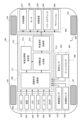
- FIG. 1 is a block diagram showing one aspect of a vehicle control system 200 mounted on a vehicle 100 such as a four-wheeled vehicle.
- the vehicle control system 200 is a system that controls motion of the vehicle 100 and includes an external world recognition section 300 , a vehicle state acquisition section 400 , a vehicle control device 500 and an actuator section 600 .
- the external world recognition unit 300 acquires external world information of the vehicle 100, in other words, information related to the traveling environment of the road on which the vehicle 100 travels.
- the external world recognition unit 300 includes a GPS (Global Positioning System) receiving unit 310, a map database 320, a road-to-vehicle communication device 330, a camera 340, a radar 350, and a LiDAR (Light Detection and Ranging, Laser Imaging Detection and Ranging) 360.
- GPS Global Positioning System
- GPS receiver 310 measures the latitude and longitude of the position of vehicle 100 by receiving signals from GPS satellites.
- Map database 320 is formed within a storage device mounted on vehicle 100 .
- the map information in the map database 320 includes information such as road positions, road shapes, and intersection positions.
- the road-to-vehicle communication device 330 transmits information of the vehicle 100 to the roadside device and receives road traffic information such as curves and intersections from the roadside device.
- the external world recognition unit 300 can include a vehicle-to-vehicle communication device that acquires road traffic information, behavior information of other vehicles, and the like from other vehicles.
- the camera 340 is a stereo camera, a monocular camera, an omnidirectional camera, or the like, and acquires image information around the vehicle 100 by photographing the surroundings of the vehicle 100 .
- Radar 350 and LiDAR 360 detect objects around vehicle 100 and output information about the detected objects.
- Objects detected by the radar 350 and the LiDAR 360 include moving objects and stationary objects.
- Vehicle state acquisition unit 400 acquires information about the state of vehicle 100 including information about the motion state of vehicle 100 .
- Vehicle state acquisition unit 400 includes wheel speed sensor 410 , acceleration sensor 420 , steering angle sensor 430 and yaw rate sensor 440 .
- Wheel speed sensor 410 is a sensor that detects the rotational speed of each wheel 101 - 104 of vehicle 100 . Then, the vehicle control device 500 calculates the speed VS of the vehicle 100 based on information on the rotation speed of each wheel 101-104 detected by the wheel speed sensor 410.
- FIG. A vehicle speed sensor for detecting the speed of vehicle 100 may be provided in place of wheel speed sensor 410 or together with wheel speed sensor 410 .
- Acceleration sensor 420 detects longitudinal acceleration and lateral acceleration (in other words, lateral acceleration) of vehicle 100 .
- Steering angle sensor 430 also detects steering angle SA, which is the wheel angle changed by electronically controlled power steering device 640 provided in vehicle 100 . Note that the steering angle sensor 430 detects the steering angle as 0 deg when the steering angle is in the steering neutral position, and detects the steering angle in the horizontal direction by distinguishing between positive and negative signs.
- Yaw rate sensor 440 detects the yaw rate of vehicle 100 .
- the vehicle control device 500 includes a microcomputer 510 as a control section (or control unit) that performs calculations based on input information and outputs calculation results.
- the microcomputer 510 includes an MPU (Microprocessor Unit), a ROM (Read Only Memory), a RAM (Random Access Memory), etc., which are not shown.
- Microcomputer 510 acquires information about the traveling environment of the road on which vehicle 100 travels, including location information of vehicle 100, road shape information, road surface information, information about objects around vehicle 100, and the like, from external world recognition unit 300. . Further, microcomputer 510 acquires information about the motion state of vehicle 100 such as speed, acceleration, steering angle, and yaw rate from vehicle state acquisition unit 400 . Then, microcomputer 510 plans a target trajectory based on the acquired various information, and outputs a control command to actuator section 600 for causing vehicle 100 to travel along the target trajectory.
- the microcomputer 510 has software functions as a surrounding situation recognition unit 511 , a target trajectory generation unit 512 , a trajectory point interval setting unit 513 , and a trajectory tracking control unit 514 .
- Surrounding situation recognition section 511 recognizes the situation around vehicle 100 based on the information on the driving environment acquired from external environment recognition section 300 and the information on the motion state of vehicle 100 acquired from vehicle state acquisition section 400 .
- the surrounding conditions of the vehicle 100 recognized by the surrounding condition recognition unit 511 include road curvature, road surface cant, road surface gradient, road surface friction coefficient ⁇ , left and right lane marker positions, left and right road edge positions, moving objects, and Contains information such as stationary objects.
- moving objects include, for example, pedestrians, bicycles, motorcycles, and other vehicles
- stationary objects include, for example, fallen objects on the road, traffic lights, guardrails, curbs, road signs, trees, billboards, and the like. be.
- the target trajectory generation unit 512 plans a target trajectory, which is a route that the vehicle 100 will automatically travel in the future, based on the surrounding conditions of the vehicle 100 recognized by the surrounding condition recognition unit 511 .
- the target trajectory (specifically, the target travel route) is expressed as a sequence of trajectory points, which are points to be reached by the vehicle 100 for each predetermined travel distance.
- the target trajectory generator 512 plans a target velocity and a target acceleration for each predetermined sampling time as target trajectory information.
- the trajectory tracking control unit 514 acquires information on the target trajectory planned by the target trajectory generation unit 512 .
- the trajectory following control unit 514 calculates a control command for causing the vehicle 100 to travel along the target trajectory, more specifically, a steering command, an acceleration command, a deceleration command, etc., and sends the calculated control command to the actuator unit 600.
- the target trajectory information includes target travel route, target speed, and target acceleration information.
- Actuator section 600 controls the motion state of vehicle 100 based on the control command from track following control section 514 .
- the actuator unit 600 includes an internal combustion engine 610 and a motor 620 that generate driving force for the vehicle 100, a braking device 630 that applies braking force to the vehicle 100, an electronically controlled power steering device 640 that changes the traveling direction of the vehicle 100, and a damping force. Equipped with an electronically controlled suspension 650 that can adjust the height and height of the vehicle. Actuator section 600 generates driving force, braking force, steering force, etc. in response to a control command from trajectory following control section 514 . Note that the trajectory following control unit 514 can operate the motor 620 as a generator to apply a braking force, that is, a regenerative braking force to the vehicle 100 .
- the trajectory point interval setting unit 513 sets the interval D [m] between the trajectory points on the target trajectory planned by the target trajectory generation unit 512 based on information about the traveling environment of the travel path on which the vehicle 100 travels or information about the state of the vehicle 100. is variably set based on setting conditions including at least one of In other words, the target trajectory generation unit 512 determines the trajectory points that the vehicle 100 should reach for each interval D set by the trajectory point interval setting unit 513 (in other words, the distance between the trajectory points).
- the microcomputer 510 mounted on the vehicle 100 sets the setting conditions including at least one of information regarding the traveling environment of the road on which the vehicle 100 travels and information regarding the state of the vehicle 100. Based on the set conditions, an interval D between a plurality of trajectory points representing a target trajectory on which the vehicle 100 is to travel is set, and a control command for causing the vehicle 100 to travel along the target trajectory is output. Execute the vehicle control method of the process.
- the information about the driving environment of the driving path includes, for example, information about the road shape of the driving path, information about the distance from the obstacle located in front of the vehicle 100 on the driving path, and information about the coefficient of friction of the road surface of the driving path. , information about the distance from the vehicle 100 traveling in front of the vehicle 100 on the road, information about the relative speed of the vehicle 100 to the preceding vehicle, information about the distance from the vehicle 100 on the road, and the like.
- the information on the road shape of the travel route includes, for example, information on the curvature of the travel route, information on the road width of the travel route, information on changes in the curvature of the travel route, and the like.
- the information about the state of the vehicle 100 is, for example, information about the motion state of the vehicle 100, information about the recognition accuracy of the external world recognition unit 300 included in the vehicle 100, and the like.
- the information about the motion state of the vehicle 100 includes, for example, information about the speed of the vehicle 100, information about the lateral jerk of the vehicle 100, information about the steering angle of the vehicle 100, and the like.
- the track point interval setting unit 513 uses a plurality of different information among the information on the traveling environment of the travel path and the information on the state of the vehicle 100 as setting conditions, and based on these different setting conditions, sets the interval between the track points. D can be set.
- the trajectory point interval setting unit 513 sets the trajectory point intervals based on the setting conditions described above, thereby ensuring the necessary trajectory following accuracy, improving the accuracy of steering angle control, and responding to changes in the driving environment. etc., and it is possible to prevent the running performance of the vehicle 100 from deteriorating under various circumstances.
- FIG. 1 shows one aspect of the vehicle control system 200, and the plurality of sensors provided in the external world recognition unit 300 and the plurality of sensors provided in the vehicle state acquisition unit 400 can be appropriately selected according to the embodiment.
- the external world recognition unit 300 does not have to include the road-to-vehicle communication device 330 .
- the track point interval setting unit 513 uses information about the road shape, more specifically, information about the curvature of the travel route of the vehicle 100 as information about the travel environment of the travel path on which the vehicle 100 travels, as a setting condition. get.
- the track point interval setting unit 513 can acquire the curvature of the travel route by referring to the map database 320 based on the position information of the vehicle 100, and can also acquire it from the roadside unit via the road-to-vehicle communication device 330.
- the track point interval setting unit 513 can acquire curvature information obtained from information such as the center line and the white line recognized by the camera 340 .
- the track point interval setting unit 513 sets the interval D [m] between track points (in other words, the distance between track points ) is narrowed.
- the curvature of the travel route of the vehicle 100 is the road curvature based on lane recognition, map data, or the like, or the curvature of the target trajectory (in other words, the target route).
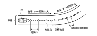
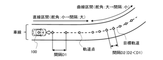
- FIG. 2 shows that when the track point spacing setting unit 513 sets the track point spacing D based on the curvature of the travel route, the track point spacing D is set to different values for straight sections and curve sections. show the situation.
- the track point interval setting unit 513 sets the interval D1 when the vehicle 100 travels on a straight section with a small curvature of the road (or the target track), and the interval D1 when the vehicle 100 travels on a curved section with a large curvature of the road.
- the interval D2 (D2 ⁇ D1) is narrowed.
- the target trajectory is expressed by arranging the trajectory points that the vehicle 100 should reach in order, if the interval D is too wide with respect to the curvature, the shape of the curve cannot be accurately expressed. Conversely, if the interval D is narrow, the number of trajectory points for representing the target trajectory of the required length will increase, and the memory capacity for storing the target trajectory (more specifically, the trajectory points) will increase. It becomes necessary to secure it, and the computational load of the microcomputer 510 increases. On the other hand, the track point interval setting unit 513 narrows the interval D as the curvature of the travel route increases. By reducing the number of trajectory points, the memory capacity can be saved and the calculation load of the microcomputer 510 can be reduced.
- FIG. 3 shows that the path error TE of the target trajectory is caused by the correlation between the trajectory point spacing D and the radius of curvature R.
- the distance .alpha the distance .
- the trajectory point interval setting unit 513 sets the trajectory point interval D to the longest possible distance within the range in which the path error TE is equal to or less than the set value ⁇ TE (in other words, the allowable maximum value). That is, the trajectory point interval setting unit 513 sets the interval D between trajectory points so as to satisfy Equation (3).
- the track point interval setting unit 513 can variably set the set value ⁇ TE according to the curvature radius R.
- the track point interval setting unit 513 determines that the radius of curvature R exceeds the set value and the travel route is a substantially straight section, the track point interval setting unit 513 sets the interval D between the track points to the maximum value Dmax. That is, the track point interval setting unit 513 shortens the space D between the track points within the range of the maximum value Dmax or less as the radius of curvature R becomes shorter.
- the track point interval setting unit 513 acquires, as a setting condition, information about the distance from an obstacle positioned in front of the vehicle 100 on the track as information about the running environment of the track on which the vehicle 100 travels. do.
- the trajectory point interval setting unit 513 sets the interval D between trajectory points to decrease as the distance from the obstacle decreases.
- the trajectory point interval setting unit 513 can acquire obstacle position information as object recognition information by the camera 340 , the radar 350 or the LiDAR 360 .
- the target trajectory generation unit 512 plans a target trajectory along which the vehicle 100 travels while avoiding the obstacle recognized by the external world recognition unit 300. .
- FIG. 4 shows a case where an obstacle OB exists on the left side of the traveling direction of the vehicle 100 as an example of setting the target trajectory when the obstacle OB exists on the travel path.
- the target trajectory generation unit 512 sets the target trajectory so as to detour on the right side of the obstacle OB so that the vehicle 100 runs avoiding the obstacle OB.
- the tracking accuracy of the vehicle 100 with respect to the route set to avoid the obstacle OB that is, the target trajectory
- the target trajectory high tracking accuracy to the target trajectory is required.
- the track point interval setting unit 513 narrows the interval D between the track points as the distance ⁇ from the obstacle OB decreases, thereby accurately expressing the target trajectory for the vehicle 100 to avoid the obstacle OB. Then, the vehicle 100 follows the target trajectory avoiding the obstacle OB with high accuracy.
- the orbit point interval setting unit 513 can set the distance ⁇ from the obstacle OB to the distance from the center of the obstacle shown in FIG. It can be the distance from the edge of the object OB in the direction in which the lane extends.
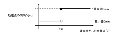
- FIG. 5 shows the characteristics of the orbital point interval setting unit 513 that proportionally decreases the orbital point interval D as the distance ⁇ from the obstacle OB becomes shorter.
- the track point interval setting unit 513 sets the distance ⁇ from the obstacle OB present in front of the vehicle 100 to the first predetermined value ⁇ 1 or more, that is, the distance away from the obstacle OB.
- the trajectory point spacing D is set to a predetermined maximum value Dmax.
- the predetermined maximum value Dmax is a normal value when no obstacle OB exists.
- the track point interval setting unit 513 increases the interval D between the track points to a predetermined maximum value Dmax as the distance ⁇ from the obstacle OB decreases. shorten proportionally from Further, the orbit point interval setting unit 513 sets the distance ⁇ from the obstacle OB to a second predetermined value ⁇ 2 ( ⁇ 1> ⁇ 2>0) or less, which is shorter than the first predetermined value ⁇ 1, that is, in the vicinity of the obstacle OB. , the interval D between the trajectory points is set to a predetermined minimum value Dmin (Dmax>Dmin>0) shorter than the predetermined maximum value Dmax.
- the predetermined minimum value Dmin is the distance D between the orbital points, which is set shorter than the normal value so as to accurately express the route that bypasses the obstacle OB.
- Fig. 6 shows the correlation between the distance D between the orbital points and the distance ⁇ from the obstacle OB by using a tanh function (hyperbolic tangent function) or the like, so that the distance D changes more smoothly with changes in the distance ⁇ .
- a tanh function hyperbolic tangent function
- the orbital point interval setting unit 513 sets the orbital point interval D to the predetermined maximum value Dmax in a region where the distance ⁇ from the obstacle OB is equal to or greater than the first predetermined value ⁇ 1.
- the distance D between the trajectory points is set to a predetermined minimum value Dmin.
- the track point interval setting unit 513 calculates the interval D between the track points using a tanh function or the like. is a characteristic expressed by , and changes with decreasing distance ⁇ from obstacle OB.
- the interval D between the orbital points is set to a predetermined maximum value Dmax (in other words, normal value) and a predetermined minimum value Dmin (in other words, a distance shorter than the normal value). That is, the orbital point interval D is not limited to the characteristic of gradually increasing or decreasing according to the change of the distance ⁇ from the obstacle OB. can be a variable that can take different binary values depending on whether the distance ⁇ is longer than or shorter than the threshold.
- the track point interval setting unit 513 acquires, as setting conditions, information on the friction coefficient ⁇ of the road surface on which the vehicle 100 travels, as information on the traveling environment of the road on which the vehicle 100 travels. is set so that the distance D between the trajectory points becomes narrower as . That is, the trajectory point interval setting unit 513 changes the trajectory point interval D according to the friction coefficient ⁇ of the travel path on which the trajectory points are set. The interval D between the track points is narrowed compared to the case where the track points are set on the traveling road with a high coefficient ⁇ .
- the track point interval setting unit 513 can acquire information on the friction coefficient ⁇ estimated from the output difference between the actual vehicle behavior and the vehicle model. In addition, the track point interval setting unit 513 can acquire information on the coefficient of friction ⁇ from the roadside unit via the road-to-vehicle communication device 330 .
- the trajectory point interval setting unit 513 narrows the interval D between the trajectory points as the friction coefficient ⁇ of the road surface becomes smaller, so that the target trajectory can be expressed accurately.
- the vehicle 100 follows the target trajectory with high accuracy.
- FIG. 8 shows changes in the distance D between the trajectory points when there are partial areas with a small friction coefficient ⁇ such as puddles and frozen portions on the road ahead of the vehicle 100 .
- the trajectory point interval setting unit 513 sets the interval D between the trajectory points to be narrower than in the case of the dry road before and after the area where the friction coefficient ⁇ is small, such as a puddle, and sets the target trajectory in the area where the friction coefficient ⁇ is small. Express accurately.
- the track point interval setting unit 513 uniformly shortens the interval D between the track points representing the target track when the friction coefficient ⁇ is reduced over the entire travel path due to rainfall or the like. Further, when the friction coefficient ⁇ of the road surface differs between the right wheel and the left wheel of the vehicle 100, the track point interval setting unit 513 sets the interval D between the track points based on, for example, the smaller one of the left and right friction coefficients ⁇ . can do.
- FIG. 9 shows the characteristic that the track point interval setting unit 513 proportionally decreases the track point interval D as the friction coefficient ⁇ of the road surface decreases.
- the track point interval setting unit 513 sets the track point interval setting unit 513 for a region where the friction coefficient ⁇ of the road surface is equal to or greater than the first predetermined value ⁇ 1, that is, for a road surface with a sufficiently high friction coefficient ⁇ such as a dry road.
- the point spacing D is set to a predetermined maximum value Dmax. That is, the first predetermined value ⁇ 1 is, for example, a threshold for distinguishing whether the road surface is a general dry road or a road surface that is more slippery than a dry road.
- the predetermined maximum value Dmax is a normal value of the distance D between the trajectory points that allows sufficient follow-up accuracy to the target trajectory on a dry road.
- the track point interval setting unit 513 When the friction coefficient ⁇ of the road surface falls below a first predetermined value ⁇ 1, the track point interval setting unit 513 shortens the interval D between the track points proportionally from a predetermined maximum value Dmax as the friction coefficient ⁇ of the road surface decreases. do. Then, the track point interval setting unit 513 sets the interval D between the track points to a predetermined minimum value Dmin in a region where the friction coefficient ⁇ of the road surface is equal to or smaller than the second predetermined value ⁇ 2 smaller than the first predetermined value ⁇ 1.
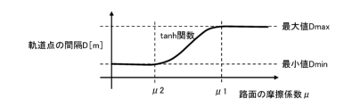
- FIG. 10 shows an example in which the correlation between the distance D between track points and the coefficient of friction ⁇ of the road surface is represented by a tanh function or the like so that the distance D changes more smoothly with respect to changes in the coefficient of friction ⁇ . show.
- the track point interval setting unit 513 sets the interval D between the track points to the predetermined maximum value Dmax in a region where the friction coefficient ⁇ of the road surface is equal to or greater than the first predetermined value ⁇ 1.
- the distance D between the track points is set to a predetermined minimum value Dmin.
- the track point interval setting unit 513 expresses the interval D between the track points using a tanh function or the like. It is a characteristic that is reduced with respect to the decrease of the friction coefficient ⁇ of the road surface.
- the track point interval setting unit 513 sets the interval D between the track points to a predetermined maximum value Dmax (in other words, normal value) and a predetermined minimum value Dmin (in other words, a distance shorter than the normal value).
- the track point interval D is not limited to the characteristic of gradually increasing or decreasing according to the change in the friction coefficient ⁇ of the road surface. It can be a variable that can take different binary values depending on whether it is smaller than or larger than the threshold.
- the track point interval setting unit 513 uses information regarding the traveling environment of the road on which the vehicle 100 travels, more specifically information regarding the shape of the road, as road width (in other words, lane width or width). is acquired as a setting condition, and as the road width of the travel path becomes narrower, the distance D between track points is narrowed.
- the track point interval setting unit 513 can acquire road width information by referring to the map database 320 based on the position information of the vehicle 100 , and can also acquire the information from the roadside unit via the road-to-vehicle communication device 330 . Further, the track point interval setting unit 513 can acquire road width information obtained from the position of the white line, road shoulder, road edge, etc. recognized by the camera 340 .
- the trajectory point interval setting unit 513 narrows the interval D between the trajectory points as the width of the travel path becomes narrower, so that the target trajectory can be represented accurately.
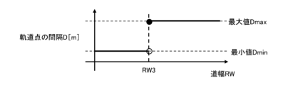
- FIG. 12 exemplifies changes in the distance D between track points when there is an area where the road width RW is partially narrowed in the middle of the straight road.
- the track point interval setting unit 513 sets the track point interval D narrower in the area where the road width RW is narrowed than when the front and rear road widths RW are relatively wide, and sets the interval D between the track points in the area where the road width RW is narrowed. accurately represent.
- the track point interval setting unit 513 uses road width RW information as map data, road width RW information obtained based on white line recognition, etc., as information on the road width RW used to set the interval D between the track points. be able to. Further, when the road width RW on which the vehicle 100 can travel is narrowed by an obstacle or the like, the track point interval setting unit 513 can use the road width RW on which the vehicle 100 can actually travel to set the interval D between the track points. can. Furthermore, when the target trajectory is set to be shifted left and right from the center of the lane, the trajectory point interval setting unit 513 can use the shorter distance from the target trajectory to the left and right road edges as information regarding the road width RW.
- FIG. 13 shows the characteristic that the track point interval setting unit 513 proportionally decreases the track point interval D as the road width RW of the travel path narrows. According to the characteristics shown in FIG. 13, the track point interval setting unit 513 sets the interval D between the track points to a predetermined maximum value Dmax (in other words, normal value).
- Dmax in other words, normal value
- the track point interval setting unit 513 proportionally shortens the track point interval D from a predetermined maximum value Dmax as the road width RW becomes narrower. .
- the track point interval setting unit 513 sets the track point interval D to a predetermined minimum value Dmin when the road width RW of the traveling path becomes equal to or smaller than a second predetermined value RW2, which is shorter than the first predetermined value RW1.
- FIG. 14 shows an example in which the correlation between the distance D between the track points and the road width RW of the traveled road is represented by a tanh function or the like, so that the distance D changes more smoothly with respect to changes in the road width RW. .
- the track point interval setting unit 513 also sets the track point interval D to the predetermined maximum value Dmax when the road width RW is equal to or greater than the first predetermined value RW1, and the road width RW is set to the predetermined maximum value Dmax. 2
- the interval D between the trajectory points is set to a predetermined minimum value Dmin.
- the track point interval setting unit 513 sets the interval D between the track points to the characteristic expressed by the tanh function or the like. , to decrease with respect to the decrease of the road width RW.
- the track point interval setting unit 513 sets the interval D between the track points to a predetermined maximum value Dmax (in other words, normal value) and a predetermined minimum value Dmin (in other words, a distance shorter than the normal value).
- the track point interval D is not limited to the characteristic of gradually increasing or decreasing according to changes in the road width RW. It can be a variable that can take different binary values depending on whether it is narrower or wider than the threshold.
- the track point interval setting unit 513 stores information about the traveling environment of the road on which the vehicle 100 travels, more specifically information about the shape of the road, as the curvature of the traveling route of the vehicle 100 (in other words, the radius of curvature).
- R is acquired as a setting condition, and the interval D between the trajectory points is set to narrow as the curvature change increases.
- a state in which the change in the curvature of the travel route is large is a state in which the steering angle (in other words, the tire angle) of the vehicle 100 changes greatly.
- the track point interval setting unit 513 narrows the interval D between the track points when the change in curvature of the travel route is large compared to when the change in curvature is small, thereby accurately expressing the shape of the target route. , to improve the accuracy of the steering angle control.
- the curvature of the travel route of the vehicle 100 is the road curvature based on lane recognition, map data, or the like, or the curvature of the target trajectory (specifically, the target route), as in the first embodiment.
- FIG. 16 illustrates how the interval D between the track points is changed according to the magnitude of the change in curvature when the vehicle 100 travels from a straight section to a curve section through a transition curve section.
- the change in curvature is small, so the interval D between the track points is set to the normal value D1.
- the change in curvature in other words, the change in steering angle
- the interval D between the track points is the normal value D1.
- the curvature change is small, so the interval D between the track points returns to the normal value D1, which is wider than the value D2 in the transition curve region.
- the track point interval setting unit 513 sets the track point interval D to A predetermined maximum value Dmax (in other words, a normal value) is used.
- the track point spacing setting unit 513 sets the track point spacing D to a predetermined minimum value Dmin (in other words, , a distance shorter than the normal value). Then, when the absolute value of the curvature change CC is within the region sandwiched between the second predetermined value CC2 and the first predetermined value CC1, the track point interval setting unit 513 sets the interval D between the track points to the absolute value of the curvature change CC. Inversely proportional to value.
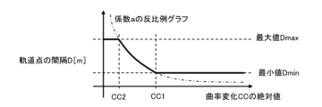
- FIG. 18 shows an example in which the interval D changes more smoothly with respect to the curvature change CC by expressing the correlation between the interval D between the orbital points and the absolute value of the curvature change CC using a tanh function or the like.
- the track point interval setting unit 513 sets the interval D between the track points to the predetermined maximum value Dmax in the region where the absolute value of the curvature change CC is equal to or less than the second predetermined value CC2, In a region where the absolute value of the curvature change CC is greater than or equal to the first predetermined value CC1 (CC2 ⁇ CC1), the distance D between the track points is set to a predetermined minimum value Dmin.
- the track point interval setting unit 513 calculates the interval D between the track points using the tanh function or the like. With the characteristic represented, a decreasing change is made for an increasing absolute value of the curvature change CC.
- the track point interval setting unit 513 acquires, as setting conditions, information about the distance from the preceding vehicle traveling in front of the vehicle 100 on the road as information about the driving environment of the road on which the vehicle 100 travels. do. Then, the track point interval setting unit 513 sets the interval D between the track points so that the shorter the distance from the preceding vehicle, in other words, the closer the area to the preceding vehicle, the narrower the distance D between the track points. Note that the track point interval setting unit 513 can acquire the position information of the preceding vehicle recognized by the camera 340, and can also acquire the position information of the preceding vehicle through inter-vehicle communication.
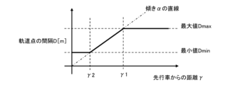
- FIG. 19 shows a state in which the distance D between the track points is narrowed as the distance ⁇ from the preceding vehicle 800 traveling in front of the vehicle 100 becomes shorter. That is, in the vicinity of the preceding vehicle 800, the distance D between the trajectory points is narrower than in the positions distant from the preceding vehicle 800 (D1>D2). High tracking accuracy is obtained for the trajectory. As a result, when the vehicle 100 approaches the preceding vehicle 800 and the following accuracy with respect to the target trajectory is required, the shape of the target trajectory is represented accurately, so the following accuracy with respect to the target trajectory can be improved.
- FIG. 20 shows the characteristic that the track point interval setting unit 513 proportionally decreases the track point interval D as the distance ⁇ from the preceding vehicle 800 decreases.
- the track point interval setting unit 513 sets the distance ⁇ from the preceding vehicle 800 to the first predetermined value ⁇ 1 or more, that is, in the region sufficiently distant from the preceding vehicle 800, the distance between the track points is Interval D is set to a predetermined maximum value Dmax.
- the track point interval setting unit 513 reduces the distance ⁇ from the preceding vehicle 800 (in other words, approaches the preceding vehicle 800) , the distance D between the trajectory points is shortened proportionally from a predetermined maximum value Dmax. Then, the track point interval setting unit 513 sets the interval D is set to a predetermined minimum value Dmin. In other words, the track point interval setting unit 513 sets the interval between the track points narrower in a region closer to the preceding vehicle 800 .
- the track point interval setting unit 513 sets information about the relative speed of the vehicle 100 with respect to the preceding vehicle traveling in front of the vehicle 100 on the road as information about the driving environment of the road on which the vehicle 100 travels. Get it as a condition. Then, the track point interval setting unit 513 sets the interval D between the track points so that it becomes narrower as the relative speed increases, in other words, as the speed of the vehicle 100 becomes faster than that of the preceding vehicle. Note that the trajectory point interval setting unit 513 can acquire the speed information of the preceding vehicle obtained from the position information of the preceding vehicle recognized by the camera 340, for example, and obtain the relative speed.
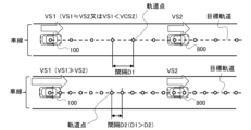
- the upper part of FIG. 21 shows the distance D1 between track points when the speed VS1 of the vehicle 100 is equal to or slower than the speed VS2 of the preceding vehicle 800 .
- the upper part of FIG. 21 shows the distance D2 between the trajectory points when the speed VS1 of the vehicle 100 is higher than the speed VS2 of the preceding vehicle 800, that is, when the relative speed of the vehicle 100 to the preceding vehicle 800 is high.
- the track point interval setting unit 513 narrows the interval D between the track points as the relative speed of the vehicle 100 with respect to the preceding vehicle 800 increases. Therefore, in the example of FIG. 21, the interval D2 is narrower than the interval D1.
- the shape of the target trajectory is represented accurately, so that the accuracy of following the target trajectory can be improved.
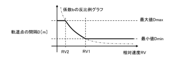
- the track point interval setting unit 513 when the relative speed RV is lower than the second predetermined value RV2, that is, when the inter-vehicle distance remains constant or when the inter-vehicle distance increases, the track point interval setting unit 513 The distance D between the trajectory points is set to a predetermined maximum value Dmax (in other words, normal value).
- the track point interval setting unit 513 sets the inter-vehicle distance. is set to a predetermined minimum value Dmin (in other words, a distance shorter than the normal value). Then, when the relative velocity is within the region sandwiched between the second predetermined value RV2 and the first predetermined value RV1, the track point interval setting unit 513 makes the interval D between the track points inversely proportional to the relative speed RV.
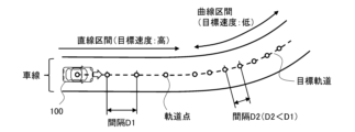
- the track point interval setting unit 513 acquires, as setting conditions, information about the distance from the vehicle 100 on the road as information about the driving environment of the road on which the vehicle 100 travels. , in other words, the closer to the vehicle 100, the narrower the distance D between the track points. That is, based on the position information of the vehicle 100, the track point interval setting unit 513 narrows the interval D between the track points as the distance from the vehicle 100 decreases.
- FIG. 23 shows a state in which the interval D between the track points is narrowed as the distance ⁇ from the vehicle 100 becomes shorter. That is, intervals D1, D2, and D3 shown in FIG. 23 indicate intervals D between track points at points having different distances ⁇ from the vehicle 100 .
- the distance ⁇ at the interval D1 is the shortest
- the distance ⁇ at the interval D2 is an intermediate value
- the distance ⁇ at the interval D3 is the longest.
- the intervals D1, D2, and D3 satisfy D3>D2>D1, and the shorter the distance ⁇ from the vehicle 100, the narrower the interval D between the trajectory points.
- the track point interval setting unit 513 widens the interval D between the track points in an area in front of the vehicle 100 which is far from the vehicle 100 and where there is time to spare before the vehicle 100 actually passes. , to reduce the computational load of the microcomputer 510 .
- the computational load of the microcomputer 510 is reduced, it becomes easier to cope with changes in the driving environment such as obstacles hidden in blind spots, merging vehicles, and oncoming vehicles.
- the trajectory point interval setting unit 513 narrows the interval D between the trajectory points in the area in front of the vehicle 100 and through which the vehicle 100 passes immediately, to accurately express the shape of the target trajectory, thereby following the target trajectory. Improve accuracy.
- FIG. 24 shows the characteristic that the track point interval setting unit 513 proportionally decreases the track point interval as the distance ⁇ from the vehicle 100 decreases.
- the track point interval setting unit 513 sets the track point interval D to a predetermined maximum value Dmax in a region where the distance ⁇ from the vehicle 100 is equal to or greater than the first predetermined value ⁇ 1.
- the distance D between the track points is set to a predetermined minimum value Dmin.
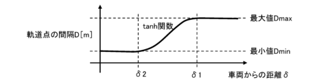
- FIG. 25 shows an example in which the correlation between the distance between track points and the distance .delta. .
- the track point interval setting unit 513 sets the interval D between the track points to the predetermined maximum value Dmax in a region where the distance ⁇ from the vehicle 100 is equal to or greater than the first predetermined value ⁇ 1, In a region where the distance ⁇ from the vehicle 100 is a second predetermined value ⁇ 2 ( ⁇ 2 ⁇ 1) or less, the distance D between the track points is set to a predetermined minimum value Dmin. Then, the track point interval setting unit 513 sets the interval D between the track points in a region where the distance ⁇ from the vehicle 100 is sandwiched between the first predetermined value ⁇ 1 and the second predetermined value ⁇ 2 by using the tanh function or the like.
- the characteristic is such that it decreases as the distance ⁇ from the vehicle 100 decreases.
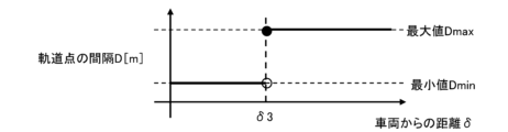
- the interval D between the track points is set to a predetermined maximum value Dmax (in other words, , normal value) and a predetermined minimum value Dmin (in other words, a distance shorter than the normal value).
- the track point interval D is not limited to the characteristic of gradually increasing or decreasing according to the change in the distance ⁇ from the vehicle 100 . It can be a variable that can take different binary values depending on whether ⁇ is longer or shorter than the threshold.
- the track point interval setting unit 513 acquires information about the state of the vehicle 100, more specifically, information about the speed VS of the vehicle 100, which is information about the motion state of the vehicle 100, as a setting condition.
- the interval D between the trajectory points is set to become narrower as the speed becomes slower.
- the speed VS of the vehicle 100 is low, the distance traveled by the vehicle 100 per unit time becomes short, and the time required to reach the next trajectory point from one trajectory point becomes longer. may decrease. Therefore, the track point interval setting unit 513 narrows the track point interval D as the speed VS of the vehicle 100 decreases, thereby ensuring the accuracy of track following when the vehicle 100 travels at a low speed.
- the track point interval setting unit 513 determines the distance D between the track points based on the speed of the vehicle 100. For example, the horizontal axis in FIGS. Instead, the characteristic at the speed VS of the vehicle 100 can be adopted.
- the speed VS of the vehicle 100 can be a target speed or an actual speed.
- the trajectory point interval setting unit 513 sets the target speed set as the target trajectory information by the target trajectory generation unit 512, or the speed calculated based on the rotational speed of each wheel 101 to 104 detected by the wheel speed sensor 410. can be obtained as information about the speed VS of the vehicle 100.
- FIG. 27 shows a case where the track point interval setting unit 513 sets the track point interval D based on the target speed set as the information of the target track, and the vehicle 100 moves through a straight section and then a curved section in the future. It shows how the interval D between the track points is changed according to the target speed when it is planned to run.
- the track point interval setting unit 513 sets the interval D between the track points based on the target speed. setting to narrow the interval D2 at .
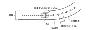
- FIG. 28 and 29 show the distance D between track points when the track point distance setting unit 513 sets the distance D between track points based on the measured value of the speed VS of the vehicle 100 (in other words, the actual speed).
- FIG. 28 shows a state in which the vehicle 100 is traveling in a straight section before the curved section, and the interval D1 is set based on the actual speed VSA of the vehicle 100 .
- FIG. 29 shows a state in which the vehicle 100 decelerates in preparation for traveling on a curved section.
- the actual speed VSB of the vehicle 100 in the curved section is lower than the actual speed VSA in the straight section, and the interval D2 based on this actual speed VSB is set narrower than the interval D1 in the straight section.
- the control for keeping the interval time constant does not change the interval distance based on the speed VS of the vehicle 100 . That is, the interval distance in the control in which the interval time is constant is uniquely determined as a result of multiplying the speed VS and the interval time, and the interval distance only changes depending on the speed VS of the vehicle 100 as a result.
- the setting of the interval D (that is, the interval distance) according to the speed VS in the ninth embodiment is a technique different from the control of keeping the interval time constant.
- the trajectory point interval setting unit 513 acquires information about the lateral jerk of the vehicle 100 as information about the motion state of the vehicle 100 as a setting condition, and the lateral jerk of the vehicle 100 increases.
- the interval D between the trajectory points is set to narrow as the distance increases.
- the trajectory point interval setting unit 513 can acquire information about the jerk in the horizontal direction obtained from the information about the acceleration in the horizontal direction detected by the acceleration sensor 420 .
- FIG. 30 shows how the distance D between the track points changes due to the difference in the lateral jerk of the vehicle 100 .
- the jerk in the left-right direction increases as the curvature changes in the transition curve section.
- the jerk in the horizontal direction becomes smaller.
- the track point interval setting unit 513 sets an interval D2 that is narrower than the interval D1 in the straight section before the transition curve section.
- the interval D is made wider than the interval D2 in the transition curve section.
- a state in which the lateral jerk of vehicle 100 is large is a state in which the steering angle change of vehicle 100 is large. Therefore, the trajectory point interval setting unit 513 narrows the interval D between the trajectory points to accurately express the shape of the target trajectory, thereby improving the accuracy of the steering angle operation.
- the track point interval setting unit 513 can set the interval D between the track points so that it narrows as the rate of change in the steering angle increases. Also in this case, the same effect as the case where the distance D between the track points is set based on the lateral jerk of the vehicle 100 can be obtained.
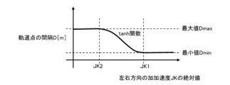
- FIG. 31 shows that the track point interval setting unit 513 sets the track point interval D according to the absolute value of the jerk JK in the left-right direction of the vehicle 100.
- the orbital point interval setting unit 513 determines that when the absolute value of the jerk JK is less than the second predetermined value JK2, that is, when the change in the left-right direction (in other words, lateral direction) acceleration is sufficiently If it is small, the interval D between the orbital points is set to a predetermined maximum value Dmax (in other words, a normal value).
- the track point interval setting unit 513 sets the interval D between the track points to a predetermined minimum value Dmin (in other words, , a distance shorter than the normal value). Then, when the absolute value of the jerk JK is within the region sandwiched between the second predetermined value JK2 and the first predetermined value JK1, the track point interval setting unit 513 sets the interval D between the track points to the value of the jerk JK. Inversely proportional to the absolute value.
- FIG. 32 shows an example in which the correlation between the distance D between the orbital points and the absolute value of the jerk JK is represented by a tanh function or the like, so that the distance D changes more smoothly with changes in the jerk JK. indicates Also in the case of the characteristics shown in FIG. 32, the track point interval setting unit 513 sets the track point interval D to the predetermined maximum value Dmax when the absolute value of the jerk JK is equal to or less than the second predetermined value JK2.
- the absolute value of the jerk JK is equal to or greater than a first predetermined value JK1 (JK2 ⁇ JK1)
- the distance D between the track points is set to a predetermined minimum value Dmin.
- the track point interval setting unit 513 calculates the interval D between the track points using the tanh function or the like. With the indicated characteristic, the change is made to decrease with respect to the increase in the absolute value of the jerk JK.
- the trajectory point interval setting unit 513 acquires information about the steering angle of the vehicle 100 as information about the motion state of the vehicle 100 as a setting condition. Set D to be narrow.
- the steering angle is the steering angle of the tire, and is the angle between the center plane of the steered wheel and the front-rear axis of the vehicle 100 .
- the trajectory point interval setting unit 513 acquires the target steering angle for causing the vehicle 100 to follow the target trajectory or the actual steering angle detected by the steering angle sensor 430 as the condition for setting the interval D between the trajectory points.
- FIG. 33 shows how the interval D between the track points changes depending on the steering angle of the vehicle 100 . Since the steering angle is small when the vehicle 100 travels in a straight section, the track point interval setting unit 513 sets the interval D between the track points to a relatively wide interval D1. Then, when the vehicle 100 enters the curved section from the straight section and the steering angle increases, the track point interval setting unit 513 sets the interval D between the track points to be larger than the interval D1 in the straight section when the steering angle is small. Set to a narrow interval D2.
- the state in which the steering angle of the vehicle 100 is large is the state in which the vehicle 100 travels on a curve with a large curvature. I can't do it. Therefore, the trajectory point interval setting unit 513 narrows the interval D between the trajectory points as the steering angle of the vehicle 100 increases, thereby improving the trajectory following accuracy when the vehicle 100 travels on a curve.
- a yaw rate or lateral acceleration may be set as a control target. Therefore, the track point interval setting unit 513 can set the interval D between the track points based on the yaw rate and the lateral acceleration instead of the steering angle information.
- the track point interval setting unit 513 can set the interval D between the track points to narrow as the yaw rate of the vehicle 100 increases. Further, the track point interval setting unit 513 can set the interval D between the track points to become narrower as the lateral acceleration of the vehicle 100 increases.
- the information about the steering angle is any of the steering angle, the yaw rate, and the lateral acceleration.
- the track point interval setting unit 513 sets the track point interval to be Let D be a predetermined maximum value Dmax (in other words, a normal value).
- the track point interval setting unit 513 sets the track point interval. is set to a predetermined minimum value Dmin (in other words, a distance shorter than the normal value).
- Dmin a distance shorter than the normal value.
- FIG. 35 shows an example in which the correlation between the distance D between track points and the absolute value of the steering angle SA is represented by a tanh function or the like, so that the distance D changes more smoothly with respect to changes in the steering angle SA.
- the track point interval setting unit 513 sets the track point interval D to the predetermined maximum value Dmax when the absolute value of the steering angle SA is equal to or less than the second predetermined value SA2,
- SA1 first predetermined value SA1
- SA1 first predetermined value SA1
- the track point interval setting unit 513 calculates the interval D between the track points using the tanh function or the like. With the characteristic shown, the change is made to decrease as the absolute value of the steering angle SA increases.
- the track point interval setting unit 513 acquires information about the recognition accuracy of the external world recognition unit 300 as information about the state of the vehicle 100, and increases the distance between track points as the recognition accuracy of the external world recognition unit 300 decreases.
- Set D to be narrow.
- the recognition accuracy of the external world recognition unit 300 acquired by the track point interval setting unit 513 as a setting condition for the interval D between the track points is the ability to identify a physical quantity. is.
- the information on the recognition accuracy of the external world recognition unit 300 is stored as the specification of the vehicle 100, and the track point interval setting unit 513 stores the information on the recognition accuracy from the non-volatile memory. can be read. Further, the information on the recognition accuracy can be information for each distance segment from the external world recognition section 300 .
- the microcomputer 510 can have a function of determining the recognition accuracy of the external world recognition unit 300 by comparing the length or distance measurement result of the external world recognition unit 300 with a specified value. Specifically, the microcomputer 510 uses the external world recognition unit 300 to measure the distance to the inter-vehicle distance confirmation sign installed on the expressway, the measurement result of the length of the white dashed line that defines the lane, and the like. The recognition accuracy (in other words, measurement error) by the recognition unit 300 can be obtained.
- the trajectory point interval setting unit 513 discriminates the length measurement error by the external world recognition unit 300 into a plurality of levels such as ⁇ 0.01 m, ⁇ 0.05 m, and ⁇ 0.1 m. By determining that the recognition accuracy of the recognition unit 300 is low, the interval D between the trajectory points can be narrowed. Note that the track point interval setting unit 513 acquires information on the distance from the vehicle 100 and information on the recognition accuracy of the external world recognition unit 300, and for example, even in areas with the same recognition accuracy, the distance from the vehicle 100 The closer the , the narrower the distance D between the trajectory points can be.
- FIG. 36 shows how the interval D between the trajectory points changes depending on the difference in the recognition accuracy of the external world recognition section 300 .
- the trajectory point interval setting unit 513 discriminates the recognition accuracy of the external world recognition unit 300 into three levels of high, medium, and low, and narrows the interval D between trajectory points in an area with lower recognition accuracy.
- the trajectory point interval setting unit 513 discriminates the measurement error of the external world recognition unit 300 into three stages such as ⁇ 0.01 m, ⁇ 0.05 m, and ⁇ 0.1 m, such as large, medium, and small, and determines the measurement error.
- the interval D between the trajectory points is narrowed in a region having a larger value.
- the trajectory point interval setting unit 513 narrows the trajectory point interval D in an area where the recognition accuracy of the external world recognition unit 300 is low, in other words, an area where the measurement error of the external world recognition unit 300 is large, to accurately determine the trajectory shape.
- the accuracy of trajectory tracking is improved.
- the first distance from the vehicle 100 is the first region with the highest recognition accuracy
- the second distance from the first distance is medium
- 1 distance is the second area where the recognition accuracy is medium
- between the second distance and the third distance is the third area where the recognition accuracy is the lowest. That is, the first area has a measurement error of ⁇ 0.01 m
- the second area has a measurement error of ⁇ 0.05 m
- the third area has a measurement error of ⁇ 0.1 m.
- the trajectory point interval setting unit 513 sets the interval D between the trajectory points in the first region to the widest interval D1, the interval D between the trajectory points in the second region to the intermediate value D2, and sets the interval D between the trajectory points in the second region to is set to the narrowest interval D3 (D3 ⁇ D2 ⁇ D1).
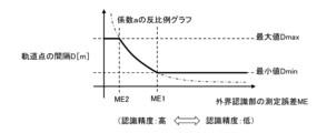
- the trajectory point interval setting unit 513 sets the trajectory Let the interval D between the points be a predetermined maximum value Dmax (in other words, a normal value).
- the trajectory point interval setting unit 513 determines that in a region where the measurement error ME of the external world recognition unit 300 exceeds the first predetermined value ME1 larger than the second predetermined value ME2, that is, in a region where the recognition accuracy of the external world recognition unit 300 is low,
- the distance D between the trajectory points is set to a predetermined minimum value Dmin (in other words, a distance shorter than the normal value).
- the track point interval setting unit 513 sets the space D between the track points to the measurement error Inversely proportional to ME.
- the track point interval setting unit 513 acquires a plurality of different pieces of information among the information on the driving environment and the information on the state of the vehicle as setting conditions, and combines the plurality of different setting conditions to set the track point. Set the interval D. Specifically, the trajectory point interval setting unit 513 sets the trajectory point interval D for each of a plurality of different setting conditions, and for example, sets the minimum value among the plurality of intervals D as the final trajectory point interval D. Select-row processing defines the spacing D between trajectory points.
- the track point interval setting unit 513 sets the interval D between track points by combining three setting conditions, for example, the curvature of the travel route, the recognition accuracy of the external world recognition unit 300, and the speed VS of the vehicle 100 . That is, as shown in the first embodiment, the track point interval setting unit 513 sets the track point interval D_C narrower as the curvature of the travel route increases. Further, as shown in the twelfth embodiment, the trajectory point interval setting unit 513 sets the trajectory point interval D_ME to Set narrow.
- the track point interval setting unit 513 narrows the track point interval D_VS as the speed VS of the vehicle 100 decreases, as shown in the ninth embodiment. Then, the trajectory point interval setting unit 513 performs select row processing to select the shortest value among the intervals D_C, D_ME, and D_VS, and provides information on the selected interval D to the target trajectory generation unit 512. .
- the method by which the trajectory point interval setting unit 513 determines the final interval D from the trajectory point intervals D obtained for each of a plurality of setting conditions is not limited to the select-low process.
- the trajectory point interval setting unit 513 selects a final interval from a plurality of intervals D obtained for each of a plurality of setting conditions by processing for obtaining an average value, processing for obtaining a median value, processing for obtaining a minimum square deviation value, and the like. D can be defined.
- the track point interval setting unit 513 can determine the final interval D by combining the main setting condition and the sub setting condition. For example, the trajectory point interval setting unit 513 selects one or a plurality of main setting conditions, and uses the interval D obtained from the main setting conditions as an input signal for select low processing.
- the trajectory point interval setting unit 513 selects one or a plurality of sub setting conditions, and only when the interval D obtained from the sub setting conditions is below a predetermined threshold value, determines from the sub setting conditions.
- the interval D is used as an input signal for the select-low process, and if the interval D obtained from the sub setting conditions is equal to or greater than a predetermined threshold, it is not included in the select-low process. Then, the trajectory point interval setting unit 513 sets the output signal of the select low process to the final interval D, and applies it to the generation of the target trajectory.
- the track point interval setting unit 513 can use, for example, the curvature of the traveling road and the distance from the preceding vehicle as the main setting condition, and the relative speed of the vehicle 100 to the preceding vehicle as the sub setting condition. Further, the trajectory point interval setting unit 513 independently sets a threshold value of the interval D for determining whether the interval D obtained from the sub setting condition is included in the target of the select low processing or not for each sub setting condition. can do.
- the track point interval setting unit 513 sets the track point interval D based on the actual speed of the vehicle 100 as shown in the ninth embodiment (see FIGS. 28 and 29), the vehicle 100 If the interval D between the trajectory points changes according to the variation of the actual speed, the trajectory may not be represented accurately when high trajectory followability is required, and the followability may be impaired.
- the actual speed of the vehicle 100 decreases, the same trajectory is represented by trajectory points with a narrower interval D, so that the trajectory shape can be accurately represented and deterioration of followability can be suppressed.
- the actual speed of the vehicle 100 increases, the same trajectory is represented by trajectory points with a wider interval D, so there is a possibility that the representation of the trajectory shape suddenly becomes rough and the followability temporarily deteriorates.
- the target trajectory generation unit 512 when the interval D between the trajectory points in the same part of the target trajectory is widened, the target trajectory generation unit 512 generates a new trajectory based on the widened interval D when the target trajectories set for the same place are superimposed. If there are a plurality of trajectory points set at the previous narrow interval D between points (in other words, if the interval D between the trajectory points suddenly widens), the trajectory points set at the previous narrow interval D Some of these can be additionally adopted. Then, the target trajectory generator 512 adds some of the trajectory points set at the previous narrow spacing D to the new trajectory points based on the widened spacing D, and generates a target trajectory in which these trajectory points are connected. to generate
- the target trajectory generating unit 512 abruptly widens the interval between the trajectory points expressing the target trajectory. can be suppressed, and it is possible to suppress deterioration of trajectory followability.
- the trajectory point interval setting unit 513 can perform processing for delaying an increase in the information on the interval D to be output to the target trajectory generation unit 512. In this case also, the interval between the trajectory points abruptly widens and trajectory following becomes difficult. It is possible to suppress the decline in sexuality.
- FIG. 38 is a state diagram showing an overview of the first trajectory point setting method
- FIG. 39 is a flow chart showing the process of the first trajectory point setting method. Referring to these, the first trajectory point setting method will be described. .
- the microcomputer 510 determines a first track point (in other words, starting point) in front of the vehicle 100 (step S901), and sets the first track point as a target point (step S902).
- the microcomputer 510 sets the interval D between track points based on the information about the driving environment of the road and/or the information about the state of the vehicle 100 (step S903).
- the microcomputer 510 determines a point separated from the object point by the distance D between the trajectory points as the next trajectory point (step S904), and sets the newly determined trajectory point as the object point (step S905).
- the microcomputer 510 determines whether or not the length of the target trajectory represented by the sequence of trajectory points is equal to or longer than a predetermined length (step S906).
- the microcomputer 510 performs processing for determining the distance D between the trajectory points (step S903), and determines the point that is the distance D between the trajectory points from the target point as the next trajectory point.
- the process (step S904) and the process (step S905) of setting the newly determined trajectory point as the target point are repeated.
- the microcomputer 510 stops setting new trajectory points.
- the first trajectory point setting method can be regarded as sampling the trajectory points actually adopted for the planned target trajectory, and simultaneously planning the target trajectory and setting the trajectory points. can also be regarded as
- the microcomputer 510 can set an evaluation function regarding the interval D between the trajectory points and optimize the target trajectory based on the evaluation function. That is, the microcomputer 510 sets the distance D between the track points based on the information about the traveling environment of the road and/or the information about the state of the vehicle 100 as the target value.
- the microcomputer 510 designs the evaluation function so that the interval D between the trajectory points representing the target trajectory approaches the target value. Then, the microcomputer 510 evaluates the interval D between the trajectory points expressing the target trajectory based on the evaluation function and sequentially optimizes it, thereby generating the trajectory point sequence based on the target interval D, that is, the target trajectory. .
- the second trajectory point setting method can be regarded as collectively performing the planning of the target trajectory and the setting of the interval D between the trajectory points.
- the track point interval setting unit 513 acquires weather information, in other words, weather information such as fine rain and wind, as information related to the traveling environment of the road on which the vehicle 100 travels, and stores the acquired weather information.
- weather information such as fine rain and wind
- an interval between trajectory points can be set.
- the trajectory point interval setting unit 513 can set the interval between the trajectory points to become narrower as the crosswind becomes stronger. This is because the stronger the crosswind, the more easily the attitude of the vehicle 100 is disturbed, and the tendency is for the ability to follow the target trajectory to deteriorate.
- the track point interval setting unit 513 can set the interval between the track points to become narrower as the visibility becomes shorter due to fog, rainfall, or the like. Visibility is the maximum distance at which an object can be clearly identified with the naked eye or the line of sight in the atmosphere. This is because the recognition accuracy (in other words, measurement accuracy) of the outside world by the camera 340 or the like decreases in a driving environment where the visibility is short due to fog, rainfall, or the like. In other words, visibility or weather such as fog or rainfall can be regarded as information relating to the recognition accuracy of the external world recognition unit 300 .
- the track point interval setting unit 513 uses road information such as bridges, tunnels, city roads, and suburban roads as information about the traveling environment of the road on which the vehicle 100 travels as conditions for setting the intervals between the track points. interval can be set.
- road information such as bridges, tunnels, city roads, and suburban roads as information about the traveling environment of the road on which the vehicle 100 travels as conditions for setting the intervals between the track points. interval can be set.
- the track point interval setting unit 513 changes the interval between the track points to be narrower when the vehicle 100 travels on a bridge, at the exit of a tunnel, or the like than when it travels in front of a bridge or in a tunnel. , trajectory followability can be ensured.
- the track point interval setting unit 513 can narrow the interval between the track points when the vehicle 100 is traveling on an urban road compared to when the vehicle is traveling on a suburban road. In other words, the track point interval setting unit 513 can set the interval between track points to become narrower as the traffic volume of vehicles and/or pedestrians increases.
- the track point interval setting unit 513 acquires information on the target acceleration/deceleration or the actual acceleration/deceleration in the longitudinal direction of the vehicle 100 as information on the motion state of the vehicle 100. As the acceleration/deceleration increases, the track point interval setting unit 513 It can be set to narrow the interval. When the vehicle 100 accelerates or decelerates suddenly, the posture of the vehicle 100 is likely to be disturbed. Therefore, the track point interval setting unit 513 narrows the interval between the track points to ensure track followability.
Abstract
In one embodiment of a vehicle control device, vehicle control method, and vehicle control system according to the present invention, setting conditions are acquired which include information pertaining to a travel environment of a travel route on which a vehicle travels and/or information pertaining to the status of the vehicle, and on the basis of the setting conditions, intervals between a plurality of trajectory points representing a target trajectory on which the vehicle is caused to travel are set, and a control command for causing the vehicle to travel along the target trajectory is outputted. It is thereby possible to minimize loss of the running performance of the vehicle even if there is a change in the conditions of the vehicle surroundings.
Description
本発明は、車両制御装置、車両制御方法、及び車両制御システムに関する。
The present invention relates to a vehicle control device, a vehicle control method, and a vehicle control system.
特許文献1の車両運転支援装置は、目標到達位置への複数の経路候補から1つの経路候補を選択経路として選択するコントローラを備え、コントローラは、複数の経路候補を計算する経路候補計算処理と、複数の経路候補の各経路コストを計算する経路コスト計算処理と、経路コストに基づいて1つの経路候補を選択経路として選択する経路選択処理と、を実行し、コントローラは、経路コスト計算処理において、目標到達位置を中心として、目標到達位置からの距離が大きくなるほど、エネルギー値が小さくなる位置エネルギーの分布を設定し、各経路候補に沿って車両の運動エネルギーと位置エネルギーの合計値を計算し、各経路候補に沿った合計値の変動成分の累積値を経路コストとして計算する。
The vehicle driving support device of Patent Document 1 includes a controller that selects one route candidate from a plurality of route candidates to a target arrival position as a selected route, and the controller performs route candidate calculation processing that calculates a plurality of route candidates, A route cost calculation process for calculating each route cost of a plurality of route candidates, and a route selection process for selecting one route candidate as a selected route based on the route costs. Setting the potential energy distribution centered on the target arrival position so that the energy value decreases as the distance from the target arrival position increases, and calculating the total value of the vehicle's kinetic energy and potential energy along each route candidate, Calculate the cumulative value of the variation component of the total value along each route candidate as the route cost.
ところで、目標軌道に沿って車両を走行させるように車両の運動状態を制御する車両制御において、目標軌道を表す複数の軌道点の間隔が常に一定であると、状況によっては車両の走行性能が低下するおそれがあった。
By the way, in vehicle control for controlling the motion state of a vehicle so that the vehicle travels along a target trajectory, if the intervals between a plurality of trajectory points representing the target trajectory are always constant, the running performance of the vehicle may deteriorate depending on the situation. there was a risk of
本発明は、従来の実情に鑑みてなされたものであり、その目的は、車両の走行性能の低下を抑制できる、車両制御装置、車両制御方法、及び車両制御システムを提供することにある。
The present invention has been made in view of the conventional circumstances, and its object is to provide a vehicle control device, a vehicle control method, and a vehicle control system that can suppress deterioration in vehicle running performance.
本発明によれば、その1つの態様において、車両が走行する走行路の走行環境に関する情報、または、前記車両の状態に関する情報の少なくとも1つを含む設定条件に基づいて、前記車両を走行させる目標軌道を表す複数の軌道点の間隔を設定する。
According to the present invention, in one aspect thereof, a target for driving the vehicle based on set conditions including at least one of information regarding the driving environment of the road on which the vehicle is driving and information regarding the state of the vehicle. Sets the spacing between trajectory points representing a trajectory.
本発明によれば、車両の走行性能の低下を抑制できる。
According to the present invention, it is possible to suppress deterioration in the running performance of the vehicle.
以下、本発明に係る車両制御装置、車両制御方法、及び車両制御システムの実施形態を、図面に基づいて説明する。
図1は、4輪自動車などの車両100に搭載される車両制御システム200の一態様を示すブロック図である。
車両制御システム200は、車両100の運動を制御するシステムであって、外界認識部300、車両状態取得部400、車両制御装置500、アクチュエータ部600を備える。 BEST MODE FOR CARRYING OUT THE INVENTION Hereinafter, embodiments of a vehicle control device, a vehicle control method, and a vehicle control system according to the present invention will be described based on the drawings.
FIG. 1 is a block diagram showing one aspect of avehicle control system 200 mounted on a vehicle 100 such as a four-wheeled vehicle.
Thevehicle control system 200 is a system that controls motion of the vehicle 100 and includes an external world recognition section 300 , a vehicle state acquisition section 400 , a vehicle control device 500 and an actuator section 600 .
図1は、4輪自動車などの車両100に搭載される車両制御システム200の一態様を示すブロック図である。
車両制御システム200は、車両100の運動を制御するシステムであって、外界認識部300、車両状態取得部400、車両制御装置500、アクチュエータ部600を備える。 BEST MODE FOR CARRYING OUT THE INVENTION Hereinafter, embodiments of a vehicle control device, a vehicle control method, and a vehicle control system according to the present invention will be described based on the drawings.
FIG. 1 is a block diagram showing one aspect of a
The
外界認識部300は、車両100の外界情報、換言すれば、車両100が走行する走行路の走行環境に関する情報を取得する。
外界認識部300は、GPS(Global Positioning System)受信部310、地図データベース320、路車間通信装置330、カメラ340、レーダ350、LiDAR(Light Detection and Ranging、Laser Imaging Detection and Ranging)360を備える。 The externalworld recognition unit 300 acquires external world information of the vehicle 100, in other words, information related to the traveling environment of the road on which the vehicle 100 travels.
The externalworld recognition unit 300 includes a GPS (Global Positioning System) receiving unit 310, a map database 320, a road-to-vehicle communication device 330, a camera 340, a radar 350, and a LiDAR (Light Detection and Ranging, Laser Imaging Detection and Ranging) 360.
外界認識部300は、GPS(Global Positioning System)受信部310、地図データベース320、路車間通信装置330、カメラ340、レーダ350、LiDAR(Light Detection and Ranging、Laser Imaging Detection and Ranging)360を備える。 The external
The external
GPS受信部310は、GPS衛星から信号を受信することにより、車両100の位置の緯度及び経度を測定する。
地図データベース320は、車両100に搭載された記憶装置内に形成される。
なお、地図データベース320の地図情報は、道路位置、道路形状、交差点位置などの情報を含む。GPS receiver 310 measures the latitude and longitude of the position of vehicle 100 by receiving signals from GPS satellites.
Map database 320 is formed within a storage device mounted on vehicle 100 .
The map information in themap database 320 includes information such as road positions, road shapes, and intersection positions.
地図データベース320は、車両100に搭載された記憶装置内に形成される。
なお、地図データベース320の地図情報は、道路位置、道路形状、交差点位置などの情報を含む。
The map information in the
路車間通信装置330は、車両100の情報を路側機に送信し、カーブや交差点などの道路交通情報を路側機から受信する。
なお、外界認識部300は、他の車両から、道路交通情報や他車の挙動情報などを取得する車車間通信装置を備えることができる。 The road-to-vehicle communication device 330 transmits information of the vehicle 100 to the roadside device and receives road traffic information such as curves and intersections from the roadside device.
Note that the externalworld recognition unit 300 can include a vehicle-to-vehicle communication device that acquires road traffic information, behavior information of other vehicles, and the like from other vehicles.
なお、外界認識部300は、他の車両から、道路交通情報や他車の挙動情報などを取得する車車間通信装置を備えることができる。 The road-to-
Note that the external
カメラ340は、ステレオカメラ、単眼カメラ、全周囲カメラなどであり、車両100の周囲を撮影して、車両100の周囲の画像情報を取得する。
レーダ350及びLiDAR360は、車両100の周囲の物体を検出し、検出した物体に関する情報を出力する。
なお、レーダ350及びLiDAR360が検出物体は、移動物体及び静止物体を含む。 Thecamera 340 is a stereo camera, a monocular camera, an omnidirectional camera, or the like, and acquires image information around the vehicle 100 by photographing the surroundings of the vehicle 100 .
Radar 350 and LiDAR 360 detect objects around vehicle 100 and output information about the detected objects.
Objects detected by theradar 350 and the LiDAR 360 include moving objects and stationary objects.
レーダ350及びLiDAR360は、車両100の周囲の物体を検出し、検出した物体に関する情報を出力する。
なお、レーダ350及びLiDAR360が検出物体は、移動物体及び静止物体を含む。 The
Objects detected by the
車両状態取得部400は、車両100の運動状態に関する情報を含む、車両100の状態に関する情報を取得する。
車両状態取得部400は、車輪速センサ410、加速度センサ420、舵角センサ430、ヨーレイトセンサ440を備える。 Vehiclestate acquisition unit 400 acquires information about the state of vehicle 100 including information about the motion state of vehicle 100 .
Vehiclestate acquisition unit 400 includes wheel speed sensor 410 , acceleration sensor 420 , steering angle sensor 430 and yaw rate sensor 440 .
車両状態取得部400は、車輪速センサ410、加速度センサ420、舵角センサ430、ヨーレイトセンサ440を備える。 Vehicle
Vehicle
車輪速センサ410は、車両100の各車輪101-104それぞれの回転速度を検出するセンサである。
そして、車両制御装置500は、車輪速センサ410が検出する各車輪101-104の回転速度の情報に基づき、車両100の速度VSを演算する。
なお、車輪速センサ410に代えて、若しくは、車輪速センサ410とともに、車両100の速度を検出する車速センサを設けることができる。Wheel speed sensor 410 is a sensor that detects the rotational speed of each wheel 101 - 104 of vehicle 100 .
Then, thevehicle control device 500 calculates the speed VS of the vehicle 100 based on information on the rotation speed of each wheel 101-104 detected by the wheel speed sensor 410. FIG.
A vehicle speed sensor for detecting the speed ofvehicle 100 may be provided in place of wheel speed sensor 410 or together with wheel speed sensor 410 .
そして、車両制御装置500は、車輪速センサ410が検出する各車輪101-104の回転速度の情報に基づき、車両100の速度VSを演算する。
なお、車輪速センサ410に代えて、若しくは、車輪速センサ410とともに、車両100の速度を検出する車速センサを設けることができる。
Then, the
A vehicle speed sensor for detecting the speed of
また、加速度センサ420は、車両100の前後方向の加速度、横方向の加速度(換言すれば、左右方向の加速度)を検出する。
また、舵角センサ430は、車両100が備える電子制御パワーステアリング装置640によって変更される車輪の角度である舵角SAを検出する。
なお、舵角センサ430は、舵角が操舵中立位置であるときに、舵角=0degとして検出し、左右方向の舵角をプラス、マイナスの符合で区別して検出する。
また、ヨーレイトセンサ440は、車両100のヨーレイトを検出する。Acceleration sensor 420 detects longitudinal acceleration and lateral acceleration (in other words, lateral acceleration) of vehicle 100 .
Steering angle sensor 430 also detects steering angle SA, which is the wheel angle changed by electronically controlled power steering device 640 provided in vehicle 100 .
Note that thesteering angle sensor 430 detects the steering angle as 0 deg when the steering angle is in the steering neutral position, and detects the steering angle in the horizontal direction by distinguishing between positive and negative signs.
Yaw rate sensor 440 detects the yaw rate of vehicle 100 .
また、舵角センサ430は、車両100が備える電子制御パワーステアリング装置640によって変更される車輪の角度である舵角SAを検出する。
なお、舵角センサ430は、舵角が操舵中立位置であるときに、舵角=0degとして検出し、左右方向の舵角をプラス、マイナスの符合で区別して検出する。
また、ヨーレイトセンサ440は、車両100のヨーレイトを検出する。
Note that the
車両制御装置500は、入力した情報に基づいて演算を行って演算結果を出力するコントロール部(若しくはコントロールユニット)としてのマイクロコンピュータ510を備える。
マイクロコンピュータ510は、図示を省略したMPU(Microprocessor Unit)、ROM(Read Only Memory)、RAM(Random Access Memory)などを備える。 Thevehicle control device 500 includes a microcomputer 510 as a control section (or control unit) that performs calculations based on input information and outputs calculation results.
Themicrocomputer 510 includes an MPU (Microprocessor Unit), a ROM (Read Only Memory), a RAM (Random Access Memory), etc., which are not shown.
マイクロコンピュータ510は、図示を省略したMPU(Microprocessor Unit)、ROM(Read Only Memory)、RAM(Random Access Memory)などを備える。 The
The
マイクロコンピュータ510は、外界認識部300から、車両100の位置情報、道路形状情報、路面情報、車両100周囲の物体に関する情報などを含む、車両100が走行する走行路の走行環境に関する情報を取得する。
また、マイクロコンピュータ510は、車両状態取得部400から、速度、加速度、舵角、ヨーレイトなどの車両100の運動状態に関する情報を取得する。
そして、マイクロコンピュータ510は、取得した各種情報に基づいて目標軌道を計画し、目標軌道に沿って車両100を走行させるための制御指令を、アクチュエータ部600に出力する。Microcomputer 510 acquires information about the traveling environment of the road on which vehicle 100 travels, including location information of vehicle 100, road shape information, road surface information, information about objects around vehicle 100, and the like, from external world recognition unit 300. .
Further,microcomputer 510 acquires information about the motion state of vehicle 100 such as speed, acceleration, steering angle, and yaw rate from vehicle state acquisition unit 400 .
Then,microcomputer 510 plans a target trajectory based on the acquired various information, and outputs a control command to actuator section 600 for causing vehicle 100 to travel along the target trajectory.
また、マイクロコンピュータ510は、車両状態取得部400から、速度、加速度、舵角、ヨーレイトなどの車両100の運動状態に関する情報を取得する。
そして、マイクロコンピュータ510は、取得した各種情報に基づいて目標軌道を計画し、目標軌道に沿って車両100を走行させるための制御指令を、アクチュエータ部600に出力する。
Further,
Then,
マイクロコンピュータ510は、周囲状況認識部511、目標軌道生成部512、軌道点間隔設定部513、軌道追従制御部514としての機能をソフトウェアとして備える。
周囲状況認識部511は、外界認識部300から取得した走行環境に関する情報、及び、車両状態取得部400から取得した車両100の運動状態に関する情報に基づき、車両100の周囲の状況を認識する。 Themicrocomputer 510 has software functions as a surrounding situation recognition unit 511 , a target trajectory generation unit 512 , a trajectory point interval setting unit 513 , and a trajectory tracking control unit 514 .
Surroundingsituation recognition section 511 recognizes the situation around vehicle 100 based on the information on the driving environment acquired from external environment recognition section 300 and the information on the motion state of vehicle 100 acquired from vehicle state acquisition section 400 .
周囲状況認識部511は、外界認識部300から取得した走行環境に関する情報、及び、車両状態取得部400から取得した車両100の運動状態に関する情報に基づき、車両100の周囲の状況を認識する。 The
Surrounding
周囲状況認識部511が認識する車両100の周囲の状況は、道路の曲率、路面カント、路面勾配、路面の摩擦係数μ、左右のレーンマーカーの位置、左右の路端位置、移動物体、及び、静止物体などの情報を含む。
なお、移動物体とは、たとえば、歩行者、自転車、オートバイ、他の車両などであり、静止物体とは、たとえば、路上の落下物、交通信号機、ガードレール、縁石、道路標識、樹木、看板などである。 The surrounding conditions of thevehicle 100 recognized by the surrounding condition recognition unit 511 include road curvature, road surface cant, road surface gradient, road surface friction coefficient μ, left and right lane marker positions, left and right road edge positions, moving objects, and Contains information such as stationary objects.
Note that moving objects include, for example, pedestrians, bicycles, motorcycles, and other vehicles, and stationary objects include, for example, fallen objects on the road, traffic lights, guardrails, curbs, road signs, trees, billboards, and the like. be.
なお、移動物体とは、たとえば、歩行者、自転車、オートバイ、他の車両などであり、静止物体とは、たとえば、路上の落下物、交通信号機、ガードレール、縁石、道路標識、樹木、看板などである。 The surrounding conditions of the
Note that moving objects include, for example, pedestrians, bicycles, motorcycles, and other vehicles, and stationary objects include, for example, fallen objects on the road, traffic lights, guardrails, curbs, road signs, trees, billboards, and the like. be.
目標軌道生成部512は、周囲状況認識部511が認識した車両100の周囲の状況に基づき、車両100が将来自動的に走行する経路である目標軌道を計画する。
目標軌道(詳細には、目標走行経路)は、所定の走行距離ごとに車両100の到達すべき地点である軌道点を、順に並べたものとして表現される。
また、目標軌道生成部512は、目標軌道の情報として、所定のサンプリング時間ごとの目標速度及び目標加速度を計画する。 The targettrajectory generation unit 512 plans a target trajectory, which is a route that the vehicle 100 will automatically travel in the future, based on the surrounding conditions of the vehicle 100 recognized by the surrounding condition recognition unit 511 .
The target trajectory (specifically, the target travel route) is expressed as a sequence of trajectory points, which are points to be reached by thevehicle 100 for each predetermined travel distance.
In addition, thetarget trajectory generator 512 plans a target velocity and a target acceleration for each predetermined sampling time as target trajectory information.
目標軌道(詳細には、目標走行経路)は、所定の走行距離ごとに車両100の到達すべき地点である軌道点を、順に並べたものとして表現される。
また、目標軌道生成部512は、目標軌道の情報として、所定のサンプリング時間ごとの目標速度及び目標加速度を計画する。 The target
The target trajectory (specifically, the target travel route) is expressed as a sequence of trajectory points, which are points to be reached by the
In addition, the
軌道追従制御部514は、目標軌道生成部512が計画した目標軌道の情報を取得する。
そして、軌道追従制御部514は、目標軌道に沿って車両100を走行させるための制御指令、詳細には、操舵指令、加速指令、減速指令などを演算し、演算した制御指令をアクチュエータ部600に出力する。
なお、目標軌道の情報は、目標走行経路、目標速度、目標加速度の各情報を含む。
アクチュエータ部600は、軌道追従制御部514からの制御指令に基づいて、車両100の運動状態を制御する。 The trajectorytracking control unit 514 acquires information on the target trajectory planned by the target trajectory generation unit 512 .
The trajectory followingcontrol unit 514 calculates a control command for causing the vehicle 100 to travel along the target trajectory, more specifically, a steering command, an acceleration command, a deceleration command, etc., and sends the calculated control command to the actuator unit 600. Output.
The target trajectory information includes target travel route, target speed, and target acceleration information.
Actuator section 600 controls the motion state of vehicle 100 based on the control command from track following control section 514 .
そして、軌道追従制御部514は、目標軌道に沿って車両100を走行させるための制御指令、詳細には、操舵指令、加速指令、減速指令などを演算し、演算した制御指令をアクチュエータ部600に出力する。
なお、目標軌道の情報は、目標走行経路、目標速度、目標加速度の各情報を含む。
アクチュエータ部600は、軌道追従制御部514からの制御指令に基づいて、車両100の運動状態を制御する。 The trajectory
The trajectory following
The target trajectory information includes target travel route, target speed, and target acceleration information.
アクチュエータ部600は、車両100の駆動力を発生する内燃機関610やモータ620、車両100に制動力を付与する制動装置630、車両100の進行方向を変えるための電子制御パワーステアリング装置640、減衰力や車高の調整が可能な電子制御サスペンション650を備える。
そして、アクチュエータ部600は、軌道追従制御部514からの制御指令を応じて、駆動力、制動力、操舵力などを発生する。
なお、軌道追従制御部514は、モータ620を発電機として作動させて制動力、つまり、回生ブレーキ力を車両100に作用させることができる。 Theactuator unit 600 includes an internal combustion engine 610 and a motor 620 that generate driving force for the vehicle 100, a braking device 630 that applies braking force to the vehicle 100, an electronically controlled power steering device 640 that changes the traveling direction of the vehicle 100, and a damping force. Equipped with an electronically controlled suspension 650 that can adjust the height and height of the vehicle.
Actuator section 600 generates driving force, braking force, steering force, etc. in response to a control command from trajectory following control section 514 .
Note that the trajectory followingcontrol unit 514 can operate the motor 620 as a generator to apply a braking force, that is, a regenerative braking force to the vehicle 100 .
そして、アクチュエータ部600は、軌道追従制御部514からの制御指令を応じて、駆動力、制動力、操舵力などを発生する。
なお、軌道追従制御部514は、モータ620を発電機として作動させて制動力、つまり、回生ブレーキ力を車両100に作用させることができる。 The
Note that the trajectory following
軌道点間隔設定部513は、目標軌道生成部512が計画する目標軌道における軌道点の間隔D[m]を、車両100が走行する走行路の走行環境に関する情報、または、車両100の状態に関する情報の少なくとも1つを含む設定条件に基づき、可変に設定する。
換言すれば、目標軌道生成部512は、軌道点間隔設定部513が設定した間隔D(換言すれば、軌道点間距離)ごとに、車両100が到達すべき地点である軌道点を定める。 The trajectory pointinterval setting unit 513 sets the interval D [m] between the trajectory points on the target trajectory planned by the target trajectory generation unit 512 based on information about the traveling environment of the travel path on which the vehicle 100 travels or information about the state of the vehicle 100. is variably set based on setting conditions including at least one of
In other words, the targettrajectory generation unit 512 determines the trajectory points that the vehicle 100 should reach for each interval D set by the trajectory point interval setting unit 513 (in other words, the distance between the trajectory points).
換言すれば、目標軌道生成部512は、軌道点間隔設定部513が設定した間隔D(換言すれば、軌道点間距離)ごとに、車両100が到達すべき地点である軌道点を定める。 The trajectory point
In other words, the target
このように、車両100に搭載されたマイクロコンピュータ510(コントロールユニット)は、車両100が走行する走行路の走行環境に関する情報、または、車両100の状態に関する情報の少なくとも1つを含む、設定条件を取得し、前記設定条件に基づいて、車両100を走行させる目標軌道を表す複数の軌道点の間隔Dを設定し、前記目標軌道に沿って車両100を走行させるための制御指令を出力する、というプロセスの車両制御方法を実行する。
In this way, the microcomputer 510 (control unit) mounted on the vehicle 100 sets the setting conditions including at least one of information regarding the traveling environment of the road on which the vehicle 100 travels and information regarding the state of the vehicle 100. Based on the set conditions, an interval D between a plurality of trajectory points representing a target trajectory on which the vehicle 100 is to travel is set, and a control command for causing the vehicle 100 to travel along the target trajectory is output. Execute the vehicle control method of the process.
ここで、走行路の走行環境に関する情報とは、たとえば、走行路の道路形状に関する情報、走行路において車両100の前方に位置する障害物からの距離に関する情報、走行路の路面の摩擦係数に関する情報、走行路において車両100の前方を走行する先行車からの距離に関する情報、先行車に対する車両100の相対速度に関する情報、走行路における車両100から距離に関する情報などである。
そして、走行路の道路形状に関する情報とは、たとえば、走行経路の曲率に関する情報、走行路の道幅に関する情報、走行経路の曲率の変化に関する情報などである。 Here, the information about the driving environment of the driving path includes, for example, information about the road shape of the driving path, information about the distance from the obstacle located in front of thevehicle 100 on the driving path, and information about the coefficient of friction of the road surface of the driving path. , information about the distance from the vehicle 100 traveling in front of the vehicle 100 on the road, information about the relative speed of the vehicle 100 to the preceding vehicle, information about the distance from the vehicle 100 on the road, and the like.
The information on the road shape of the travel route includes, for example, information on the curvature of the travel route, information on the road width of the travel route, information on changes in the curvature of the travel route, and the like.
そして、走行路の道路形状に関する情報とは、たとえば、走行経路の曲率に関する情報、走行路の道幅に関する情報、走行経路の曲率の変化に関する情報などである。 Here, the information about the driving environment of the driving path includes, for example, information about the road shape of the driving path, information about the distance from the obstacle located in front of the
The information on the road shape of the travel route includes, for example, information on the curvature of the travel route, information on the road width of the travel route, information on changes in the curvature of the travel route, and the like.
また、車両100の状態に関する情報とは、たとえば、車両100の運動状態に関する情報、車両100が備える外界認識部300の認識精度に関する情報などである。
そして、車両100の運動状態に関する情報とは、たとえば、車両100の速度に関する情報、車両100の左右方向の加加速度に関する情報、車両100の舵角に関する情報などである。 The information about the state of thevehicle 100 is, for example, information about the motion state of the vehicle 100, information about the recognition accuracy of the external world recognition unit 300 included in the vehicle 100, and the like.
The information about the motion state of thevehicle 100 includes, for example, information about the speed of the vehicle 100, information about the lateral jerk of the vehicle 100, information about the steering angle of the vehicle 100, and the like.
そして、車両100の運動状態に関する情報とは、たとえば、車両100の速度に関する情報、車両100の左右方向の加加速度に関する情報、車両100の舵角に関する情報などである。 The information about the state of the
The information about the motion state of the
また、軌道点間隔設定部513は、走行路の走行環境に関する情報及び車両100の状態に関する情報のうちの複数の異なる情報を設定条件とし、これら複数の異なる設定条件に基づいて、軌道点の間隔Dを設定することができる。
そして、軌道点間隔設定部513が、上記のような設定条件に基づき軌道点の間隔を設定することで、必要な軌道追従精度の確保、舵角制御の精度向上、走行環境の変化への対応などを実現でき、種々の状況下で車両100の走行性能が低下することを抑止できる。
尚、図1は車両制御システム200の一態様であり、外界認識部300が備える複数のセンサおよび車両状態取得部400が備える複数のセンサは、実施形態に応じて適宜選択することができる。
たとえば、後述するように路車間通信を必要としない実施形態を採用する場合には、外界認識部300は路車間通信装置330を備えていなくても良い。 Further, the track pointinterval setting unit 513 uses a plurality of different information among the information on the traveling environment of the travel path and the information on the state of the vehicle 100 as setting conditions, and based on these different setting conditions, sets the interval between the track points. D can be set.
The trajectory pointinterval setting unit 513 sets the trajectory point intervals based on the setting conditions described above, thereby ensuring the necessary trajectory following accuracy, improving the accuracy of steering angle control, and responding to changes in the driving environment. etc., and it is possible to prevent the running performance of the vehicle 100 from deteriorating under various circumstances.
Note that FIG. 1 shows one aspect of thevehicle control system 200, and the plurality of sensors provided in the external world recognition unit 300 and the plurality of sensors provided in the vehicle state acquisition unit 400 can be appropriately selected according to the embodiment.
For example, when adopting an embodiment that does not require road-to-vehicle communication as described later, the externalworld recognition unit 300 does not have to include the road-to-vehicle communication device 330 .
そして、軌道点間隔設定部513が、上記のような設定条件に基づき軌道点の間隔を設定することで、必要な軌道追従精度の確保、舵角制御の精度向上、走行環境の変化への対応などを実現でき、種々の状況下で車両100の走行性能が低下することを抑止できる。
尚、図1は車両制御システム200の一態様であり、外界認識部300が備える複数のセンサおよび車両状態取得部400が備える複数のセンサは、実施形態に応じて適宜選択することができる。
たとえば、後述するように路車間通信を必要としない実施形態を採用する場合には、外界認識部300は路車間通信装置330を備えていなくても良い。 Further, the track point
The trajectory point
Note that FIG. 1 shows one aspect of the
For example, when adopting an embodiment that does not require road-to-vehicle communication as described later, the external
以下では、軌道点間隔設定部513の態様を、詳細に説明する。
「第1実施形態」
第1実施形態において、軌道点間隔設定部513は、車両100が走行する走行路の走行環境に関する情報として、道路形状に関する情報、詳細には、車両100の走行経路の曲率に関する情報を設定条件として取得する。
軌道点間隔設定部513は、走行経路の曲率を、車両100の位置情報に基づき地図データベース320を参照することで取得でき、また、路車間通信装置330を介して路側機から取得することができる。
また、軌道点間隔設定部513は、カメラ340によって認識されたセンターラインや白線などの情報から求められた曲率の情報を取得することができる。 In the following, aspects of the trajectory pointinterval setting unit 513 will be described in detail.
"First Embodiment"
In the first embodiment, the track pointinterval setting unit 513 uses information about the road shape, more specifically, information about the curvature of the travel route of the vehicle 100 as information about the travel environment of the travel path on which the vehicle 100 travels, as a setting condition. get.
The track pointinterval setting unit 513 can acquire the curvature of the travel route by referring to the map database 320 based on the position information of the vehicle 100, and can also acquire it from the roadside unit via the road-to-vehicle communication device 330. .
Further, the track pointinterval setting unit 513 can acquire curvature information obtained from information such as the center line and the white line recognized by the camera 340 .
「第1実施形態」
第1実施形態において、軌道点間隔設定部513は、車両100が走行する走行路の走行環境に関する情報として、道路形状に関する情報、詳細には、車両100の走行経路の曲率に関する情報を設定条件として取得する。
軌道点間隔設定部513は、走行経路の曲率を、車両100の位置情報に基づき地図データベース320を参照することで取得でき、また、路車間通信装置330を介して路側機から取得することができる。
また、軌道点間隔設定部513は、カメラ340によって認識されたセンターラインや白線などの情報から求められた曲率の情報を取得することができる。 In the following, aspects of the trajectory point
"First Embodiment"
In the first embodiment, the track point
The track point
Further, the track point
そして、軌道点間隔設定部513は、走行経路の曲率が大きくなるにつれて、換言すれば、走行経路の曲率半径が小さくなるほど、軌道点の間隔D[m](換言すれば、軌道点間の距離)が狭くなるように設定する。
ここで、車両100の走行経路の曲率とは、車線認識や地図データなどに基づく道路曲率、または、目標軌道(換言すれば、目標経路)の曲率である。 Then, the track pointinterval setting unit 513 sets the interval D [m] between track points (in other words, the distance between track points ) is narrowed.
Here, the curvature of the travel route of thevehicle 100 is the road curvature based on lane recognition, map data, or the like, or the curvature of the target trajectory (in other words, the target route).
ここで、車両100の走行経路の曲率とは、車線認識や地図データなどに基づく道路曲率、または、目標軌道(換言すれば、目標経路)の曲率である。 Then, the track point
Here, the curvature of the travel route of the
図2は、軌道点間隔設定部513が、走行経路の曲率に基づいて軌道点の間隔Dを設定したときに、軌道点の間隔Dが、直線区間とカーブ区間とで異なる値に設定される様子を示す。
軌道点間隔設定部513は、道路(若しくは目標軌道)の曲率が小さい直線区間を車両100が走行するときの間隔D1に比べて、道路の曲率が大きくなるカーブ区間を車両100が走行するときの間隔D2(D2<D1)を狭くする。 FIG. 2 shows that when the track pointspacing setting unit 513 sets the track point spacing D based on the curvature of the travel route, the track point spacing D is set to different values for straight sections and curve sections. show the situation.
The track pointinterval setting unit 513 sets the interval D1 when the vehicle 100 travels on a straight section with a small curvature of the road (or the target track), and the interval D1 when the vehicle 100 travels on a curved section with a large curvature of the road. The interval D2 (D2<D1) is narrowed.
軌道点間隔設定部513は、道路(若しくは目標軌道)の曲率が小さい直線区間を車両100が走行するときの間隔D1に比べて、道路の曲率が大きくなるカーブ区間を車両100が走行するときの間隔D2(D2<D1)を狭くする。 FIG. 2 shows that when the track point
The track point
車両100の到達すべき地点である軌道点を順に並べて目標軌道を表現する場合、曲率に対して間隔Dが広すぎると、カーブの形状を正確に表現することができなくなる。
逆に、間隔Dが狭いと、必要な長さの目標軌道を表すための軌道点の数が多くなって、目標軌道(詳細には、軌道点)を記憶しておくためのメモリ容量を多く確保する必要が生じ、また、マイクロコンピュータ510の演算負荷が多くなる。
これに対し、軌道点間隔設定部513は、走行経路の曲率が大きくなるにつれて間隔Dを狭くするから、カーブの形状を必要な精度で表現して軌道追従の精度を維持でき、また、直線区間では軌道点の数を減らすことで、メモリ容量の節約、マイクロコンピュータ510の演算負荷の軽減を実現できる。 When the target trajectory is expressed by arranging the trajectory points that thevehicle 100 should reach in order, if the interval D is too wide with respect to the curvature, the shape of the curve cannot be accurately expressed.
Conversely, if the interval D is narrow, the number of trajectory points for representing the target trajectory of the required length will increase, and the memory capacity for storing the target trajectory (more specifically, the trajectory points) will increase. It becomes necessary to secure it, and the computational load of themicrocomputer 510 increases.
On the other hand, the track pointinterval setting unit 513 narrows the interval D as the curvature of the travel route increases. By reducing the number of trajectory points, the memory capacity can be saved and the calculation load of the microcomputer 510 can be reduced.
逆に、間隔Dが狭いと、必要な長さの目標軌道を表すための軌道点の数が多くなって、目標軌道(詳細には、軌道点)を記憶しておくためのメモリ容量を多く確保する必要が生じ、また、マイクロコンピュータ510の演算負荷が多くなる。
これに対し、軌道点間隔設定部513は、走行経路の曲率が大きくなるにつれて間隔Dを狭くするから、カーブの形状を必要な精度で表現して軌道追従の精度を維持でき、また、直線区間では軌道点の数を減らすことで、メモリ容量の節約、マイクロコンピュータ510の演算負荷の軽減を実現できる。 When the target trajectory is expressed by arranging the trajectory points that the
Conversely, if the interval D is narrow, the number of trajectory points for representing the target trajectory of the required length will increase, and the memory capacity for storing the target trajectory (more specifically, the trajectory points) will increase. It becomes necessary to secure it, and the computational load of the
On the other hand, the track point
図3は、目標軌道の経路誤差TEが、軌道点の間隔Dと曲率半径Rとの相関によって生じることを示す。
ここで、隣接する2つの軌道点を結ぶ直線と、曲率半径Rの中心との距離αは、数式1で求まる。

FIG. 3 shows that the path error TE of the target trajectory is caused by the correlation between the trajectory point spacing D and the radius of curvature R. FIG.
Here, the distance .alpha.
ここで、隣接する2つの軌道点を結ぶ直線と、曲率半径Rの中心との距離αは、数式1で求まる。
Here, the distance .alpha.
したがって、経路誤差TEは、数式2で求まる。

Therefore, the path error TE is obtained by Equation (2).
ここで、軌道点間隔設定部513は、軌道点の間隔Dを、経路誤差TEが設定値ΔTE(換言すれば、許容最大値)以下となる範囲内で可及的な長い距離に設定する。
つまり、軌道点間隔設定部513は、軌道点の間隔Dを、数式3を満たすように設定する。

Here, the trajectory point interval setting unit 513 sets the trajectory point interval D to the longest possible distance within the range in which the path error TE is equal to or less than the set value ΔTE (in other words, the allowable maximum value).
That is, the trajectory pointinterval setting unit 513 sets the interval D between trajectory points so as to satisfy Equation (3).
つまり、軌道点間隔設定部513は、軌道点の間隔Dを、数式3を満たすように設定する。
That is, the trajectory point
なお、軌道点間隔設定部513は、設定値ΔTEを曲率半径Rに応じて可変に設定することができる。
また、軌道点間隔設定部513は、曲率半径Rが設定値を超え、走行経路が略直線区間であると判断した場合、軌道点の間隔Dを、最大値Dmaxに設定する。
つまり、軌道点間隔設定部513は、曲率半径Rが短くなるにつれて、軌道点の間隔Dを最大値Dmax以下の範囲でより短くする。 Note that the track pointinterval setting unit 513 can variably set the set value ΔTE according to the curvature radius R.
When the track pointinterval setting unit 513 determines that the radius of curvature R exceeds the set value and the travel route is a substantially straight section, the track point interval setting unit 513 sets the interval D between the track points to the maximum value Dmax.
That is, the track pointinterval setting unit 513 shortens the space D between the track points within the range of the maximum value Dmax or less as the radius of curvature R becomes shorter.
また、軌道点間隔設定部513は、曲率半径Rが設定値を超え、走行経路が略直線区間であると判断した場合、軌道点の間隔Dを、最大値Dmaxに設定する。
つまり、軌道点間隔設定部513は、曲率半径Rが短くなるにつれて、軌道点の間隔Dを最大値Dmax以下の範囲でより短くする。 Note that the track point
When the track point
That is, the track point
「第2実施形態」
第2実施形態において、軌道点間隔設定部513は、車両100が走行する走行路の走行環境に関する情報として、走行路において車両100の前方に位置する障害物からの距離に関する情報を設定条件として取得する。
そして、軌道点間隔設定部513は、障害物からの距離が短くなるにつれて、軌道点の間隔Dが狭くなるように設定する。
軌道点間隔設定部513は、障害物の位置情報を、カメラ340、レーダ350或いはLiDAR360による物体の認識情報として取得することができる。
ここで、走行路上に車両100の走行の障害となる障害物が存在する場合、目標軌道生成部512は、外界認識部300が認識した障害物を避けて車両100が走行する目標軌道を計画する。 "Second Embodiment"
In the second embodiment, the track pointinterval setting unit 513 acquires, as a setting condition, information about the distance from an obstacle positioned in front of the vehicle 100 on the track as information about the running environment of the track on which the vehicle 100 travels. do.
The trajectory pointinterval setting unit 513 sets the interval D between trajectory points to decrease as the distance from the obstacle decreases.
The trajectory pointinterval setting unit 513 can acquire obstacle position information as object recognition information by the camera 340 , the radar 350 or the LiDAR 360 .
Here, if there is an obstacle that hinders the travel of thevehicle 100 on the travel path, the target trajectory generation unit 512 plans a target trajectory along which the vehicle 100 travels while avoiding the obstacle recognized by the external world recognition unit 300. .
第2実施形態において、軌道点間隔設定部513は、車両100が走行する走行路の走行環境に関する情報として、走行路において車両100の前方に位置する障害物からの距離に関する情報を設定条件として取得する。
そして、軌道点間隔設定部513は、障害物からの距離が短くなるにつれて、軌道点の間隔Dが狭くなるように設定する。
軌道点間隔設定部513は、障害物の位置情報を、カメラ340、レーダ350或いはLiDAR360による物体の認識情報として取得することができる。
ここで、走行路上に車両100の走行の障害となる障害物が存在する場合、目標軌道生成部512は、外界認識部300が認識した障害物を避けて車両100が走行する目標軌道を計画する。 "Second Embodiment"
In the second embodiment, the track point
The trajectory point
The trajectory point
Here, if there is an obstacle that hinders the travel of the
図4は、走行路に障害物OBが存在する場合の目標軌道の設定例として、車両100の進行方向左側に障害物OBが存在する場合を示す。
このとき、目標軌道生成部512は、車両100が障害物OBを避けて走行するように、目標軌道を、障害物OBの右側を迂回するように設定する。
ここで、障害物OBを避けるように設定された経路(つまり、目標軌道)に対する車両100の追従精度が低いと、車両100が障害物OBと接触するなどのおそれがあり、障害物OB付近において目標軌道への高い追従精度が求められる。 FIG. 4 shows a case where an obstacle OB exists on the left side of the traveling direction of thevehicle 100 as an example of setting the target trajectory when the obstacle OB exists on the travel path.
At this time, the targettrajectory generation unit 512 sets the target trajectory so as to detour on the right side of the obstacle OB so that the vehicle 100 runs avoiding the obstacle OB.
Here, if the tracking accuracy of thevehicle 100 with respect to the route set to avoid the obstacle OB (that is, the target trajectory) is low, there is a risk that the vehicle 100 will come into contact with the obstacle OB. High tracking accuracy to the target trajectory is required.
このとき、目標軌道生成部512は、車両100が障害物OBを避けて走行するように、目標軌道を、障害物OBの右側を迂回するように設定する。
ここで、障害物OBを避けるように設定された経路(つまり、目標軌道)に対する車両100の追従精度が低いと、車両100が障害物OBと接触するなどのおそれがあり、障害物OB付近において目標軌道への高い追従精度が求められる。 FIG. 4 shows a case where an obstacle OB exists on the left side of the traveling direction of the
At this time, the target
Here, if the tracking accuracy of the
そこで、軌道点間隔設定部513は、障害物OBからの距離βが近いほど軌道点の間隔Dを狭くすることで、車両100が障害物OBを避けて走行するための目標軌道を正確に表現し、障害物OBを避ける目標軌道に車両100が高い精度で追従するようにする。
なお、軌道点間隔設定部513は、障害物OBからの距離βを、図4に示した障害物の中心からの距離とすることができ、また、障害物OBからの最短距離、或いは、障害物OBの端部から車線の延びる方向への距離とすることができる。 Therefore, the track pointinterval setting unit 513 narrows the interval D between the track points as the distance β from the obstacle OB decreases, thereby accurately expressing the target trajectory for the vehicle 100 to avoid the obstacle OB. Then, the vehicle 100 follows the target trajectory avoiding the obstacle OB with high accuracy.
Note that the orbit pointinterval setting unit 513 can set the distance β from the obstacle OB to the distance from the center of the obstacle shown in FIG. It can be the distance from the edge of the object OB in the direction in which the lane extends.
なお、軌道点間隔設定部513は、障害物OBからの距離βを、図4に示した障害物の中心からの距離とすることができ、また、障害物OBからの最短距離、或いは、障害物OBの端部から車線の延びる方向への距離とすることができる。 Therefore, the track point
Note that the orbit point
以下では、障害物OBからの距離βに応じた軌道点の間隔Dの決め方を、詳細に設定する。
図5は、軌道点間隔設定部513が、障害物OBからの距離βが短くなるにつれて、軌道点の間隔Dを比例的に減少させる特性を示す。
図5に示した特性によると、軌道点間隔設定部513は、車両100の前方に存在する障害物OBからの距離βが第1所定値β1以上である領域、つまり、障害物OBから離れた領域では、軌道点の間隔Dを所定の最大値Dmaxに設定する。
なお、所定の最大値Dmaxとは、障害物OBが存在しないときの通常値である。 In the following, the method of determining the interval D between the orbital points according to the distance β from the obstacle OB will be set in detail.
FIG. 5 shows the characteristics of the orbital pointinterval setting unit 513 that proportionally decreases the orbital point interval D as the distance β from the obstacle OB becomes shorter.
According to the characteristics shown in FIG. 5, the track pointinterval setting unit 513 sets the distance β from the obstacle OB present in front of the vehicle 100 to the first predetermined value β1 or more, that is, the distance away from the obstacle OB. In the region, the trajectory point spacing D is set to a predetermined maximum value Dmax.
The predetermined maximum value Dmax is a normal value when no obstacle OB exists.
図5は、軌道点間隔設定部513が、障害物OBからの距離βが短くなるにつれて、軌道点の間隔Dを比例的に減少させる特性を示す。
図5に示した特性によると、軌道点間隔設定部513は、車両100の前方に存在する障害物OBからの距離βが第1所定値β1以上である領域、つまり、障害物OBから離れた領域では、軌道点の間隔Dを所定の最大値Dmaxに設定する。
なお、所定の最大値Dmaxとは、障害物OBが存在しないときの通常値である。 In the following, the method of determining the interval D between the orbital points according to the distance β from the obstacle OB will be set in detail.
FIG. 5 shows the characteristics of the orbital point
According to the characteristics shown in FIG. 5, the track point
The predetermined maximum value Dmax is a normal value when no obstacle OB exists.
そして、障害物OBからの距離βが第1所定値β1を下回る領域では、軌道点間隔設定部513は、障害物OBからの距離βが短くなるにつれて軌道点の間隔Dを所定の最大値Dmaxから比例的に短くする。
また、軌道点間隔設定部513は、障害物OBからの距離βが第1所定値β1よりも短い第2所定値β2(β1>β2>0)以下の領域、つまり、障害物OBの付近では、軌道点の間隔Dを、所定の最大値Dmaxよりも短い所定の最小値Dmin(Dmax>Dmin>0)に設定する。
所定の最小値Dminは、障害物OBを迂回する経路を正確に表すことができるように、通常値よりも短く設定した、軌道点の間隔Dである。 In a region where the distance β from the obstacle OB is less than the first predetermined value β1, the track pointinterval setting unit 513 increases the interval D between the track points to a predetermined maximum value Dmax as the distance β from the obstacle OB decreases. shorten proportionally from
Further, the orbit pointinterval setting unit 513 sets the distance β from the obstacle OB to a second predetermined value β2 (β1>β2>0) or less, which is shorter than the first predetermined value β1, that is, in the vicinity of the obstacle OB. , the interval D between the trajectory points is set to a predetermined minimum value Dmin (Dmax>Dmin>0) shorter than the predetermined maximum value Dmax.
The predetermined minimum value Dmin is the distance D between the orbital points, which is set shorter than the normal value so as to accurately express the route that bypasses the obstacle OB.
また、軌道点間隔設定部513は、障害物OBからの距離βが第1所定値β1よりも短い第2所定値β2(β1>β2>0)以下の領域、つまり、障害物OBの付近では、軌道点の間隔Dを、所定の最大値Dmaxよりも短い所定の最小値Dmin(Dmax>Dmin>0)に設定する。
所定の最小値Dminは、障害物OBを迂回する経路を正確に表すことができるように、通常値よりも短く設定した、軌道点の間隔Dである。 In a region where the distance β from the obstacle OB is less than the first predetermined value β1, the track point
Further, the orbit point
The predetermined minimum value Dmin is the distance D between the orbital points, which is set shorter than the normal value so as to accurately express the route that bypasses the obstacle OB.
なお、障害物OBからの距離βの変化に対する軌道点の間隔Dの変化は、定数倍の関係に限定されない。
図6は、軌道点の間隔Dと、障害物OBからの距離βとの相関を、tanh関数(ハイパボリックタンジェント関数)などによって表すことで、距離βの変化に対して間隔Dがより滑らかに変化するようにした例を示す。 Note that the change in the distance D between the orbital points with respect to the change in the distance β from the obstacle OB is not limited to a constant multiple relationship.
Fig. 6 shows the correlation between the distance D between the orbital points and the distance β from the obstacle OB by using a tanh function (hyperbolic tangent function) or the like, so that the distance D changes more smoothly with changes in the distance β. Here is an example where
図6の場合も、軌道点間隔設定部513は、障害物OBからの距離βが第1所定値β1以上の領域では、軌道点の間隔Dを所定の最大値Dmaxに設定し、障害物OBからの距離βが第2所定値β2(β2<β1)以下の領域では、軌道点の間隔Dを所定の最小値Dminに設定する。
そして、軌道点間隔設定部513は、障害物OBからの距離βが第1所定値β1と第2所定値β2とで挟まれる領域内であるときは、軌道点の間隔Dを、tanh関数などで表される特性で、障害物OBからの距離βの減少に対して減少変化させる。 In the case of FIG. 6 as well, the orbital pointinterval setting unit 513 sets the orbital point interval D to the predetermined maximum value Dmax in a region where the distance β from the obstacle OB is equal to or greater than the first predetermined value β1. In a region where the distance β from the trajectory point is equal to or less than a second predetermined value β2 (β2<β1), the distance D between the trajectory points is set to a predetermined minimum value Dmin.
Then, when the distance β from the obstacle OB is within the region sandwiched between the first predetermined value β1 and the second predetermined value β2, the track pointinterval setting unit 513 calculates the interval D between the track points using a tanh function or the like. is a characteristic expressed by , and changes with decreasing distance β from obstacle OB.
そして、軌道点間隔設定部513は、障害物OBからの距離βが第1所定値β1と第2所定値β2とで挟まれる領域内であるときは、軌道点の間隔Dを、tanh関数などで表される特性で、障害物OBからの距離βの減少に対して減少変化させる。 In the case of FIG. 6 as well, the orbital point
Then, when the distance β from the obstacle OB is within the region sandwiched between the first predetermined value β1 and the second predetermined value β2, the track point
図7は、障害物OBからの距離βが所定値β3(所定値β3>0[m])よりも長いか短いかに応じて、軌道点の間隔Dを所定の最大値Dmax(換言すれば、通常値)と所定の最小値Dmin(換言すれば、通常値よりも短い距離)とのいずれか一方に切り替える特性を示す。
つまり、軌道点の間隔Dを、障害物OBからの距離βの変化に応じて漸増、漸減させる特性に限定されず、軌道点間隔設定部513は、軌道点の間隔Dを、障害物OBからの距離βが閾値よりも長い場合と短い場合とで異なる2値の値をとり得る変数とすることができる。 7, the interval D between the orbital points is set to a predetermined maximum value Dmax (in other words, normal value) and a predetermined minimum value Dmin (in other words, a distance shorter than the normal value).
That is, the orbital point interval D is not limited to the characteristic of gradually increasing or decreasing according to the change of the distance β from the obstacle OB. can be a variable that can take different binary values depending on whether the distance β is longer than or shorter than the threshold.
「第3実施形態」
第3実施形態において、軌道点間隔設定部513は、車両100が走行する走行路の走行環境に関する情報として、走行路の路面の摩擦係数μに関する情報を設定条件として取得し、路面の摩擦係数μが小さくなるにつれて、軌道点の間隔Dが狭くなるように設定する。
つまり、軌道点間隔設定部513は、軌道点を設定する走行路の摩擦係数μに応じて軌道点の間隔Dを変更し、摩擦係数μが低い走行路に軌道点を設定する場合は、摩擦係数μが高い走行路に軌道点を設定する場合に比べて、軌道点の間隔Dを狭くする。 "Third Embodiment"
In the third embodiment, the track pointinterval setting unit 513 acquires, as setting conditions, information on the friction coefficient μ of the road surface on which the vehicle 100 travels, as information on the traveling environment of the road on which the vehicle 100 travels. is set so that the distance D between the trajectory points becomes narrower as .
That is, the trajectory pointinterval setting unit 513 changes the trajectory point interval D according to the friction coefficient μ of the travel path on which the trajectory points are set. The interval D between the track points is narrowed compared to the case where the track points are set on the traveling road with a high coefficient μ.
第3実施形態において、軌道点間隔設定部513は、車両100が走行する走行路の走行環境に関する情報として、走行路の路面の摩擦係数μに関する情報を設定条件として取得し、路面の摩擦係数μが小さくなるにつれて、軌道点の間隔Dが狭くなるように設定する。
つまり、軌道点間隔設定部513は、軌道点を設定する走行路の摩擦係数μに応じて軌道点の間隔Dを変更し、摩擦係数μが低い走行路に軌道点を設定する場合は、摩擦係数μが高い走行路に軌道点を設定する場合に比べて、軌道点の間隔Dを狭くする。 "Third Embodiment"
In the third embodiment, the track point
That is, the trajectory point
なお、軌道点間隔設定部513は、実際の車両挙動と車両モデルの出力差から推定された摩擦係数μの情報を取得することができる。
また、軌道点間隔設定部513は、路車間通信装置330を介して路側機から摩擦係数μの情報を取得することができる。 Note that the track pointinterval setting unit 513 can acquire information on the friction coefficient μ estimated from the output difference between the actual vehicle behavior and the vehicle model.
In addition, the track pointinterval setting unit 513 can acquire information on the coefficient of friction μ from the roadside unit via the road-to-vehicle communication device 330 .
また、軌道点間隔設定部513は、路車間通信装置330を介して路側機から摩擦係数μの情報を取得することができる。 Note that the track point
In addition, the track point
車両100が摩擦係数μの小さい路面を走行する場合、車両100の車輪が滑り易く、目標軌道への追従精度が低下する可能性がある。
そこで、軌道点間隔設定部513は、路面の摩擦係数μが小さくなるにつれて軌道点の間隔Dを狭くすることで、目標軌道を正確に表現できるようにし、路面の摩擦係数μが小さく滑り易い路面を車両100が走行するときに、車両100が高い精度で目標軌道に追従するようにする。 When thevehicle 100 travels on a road surface with a small coefficient of friction μ, the wheels of the vehicle 100 are likely to slip, and there is a possibility that the accuracy of following the target trajectory will decrease.
Therefore, the trajectory pointinterval setting unit 513 narrows the interval D between the trajectory points as the friction coefficient μ of the road surface becomes smaller, so that the target trajectory can be expressed accurately. When the vehicle 100 travels, the vehicle 100 follows the target trajectory with high accuracy.
そこで、軌道点間隔設定部513は、路面の摩擦係数μが小さくなるにつれて軌道点の間隔Dを狭くすることで、目標軌道を正確に表現できるようにし、路面の摩擦係数μが小さく滑り易い路面を車両100が走行するときに、車両100が高い精度で目標軌道に追従するようにする。 When the
Therefore, the trajectory point
図8は、車両100の前方の走行路に水溜まりや氷結部分などの摩擦係数μが小さい領域が部分的に存在する場合における、軌道点の間隔Dの変化を示す。
この場合、軌道点間隔設定部513は、水溜まりなどの摩擦係数μが小さい領域では、軌道点の間隔Dを前後の乾燥路のときよりも狭く設定し、摩擦係数μが小さい領域において目標軌道を正確に表現する。 FIG. 8 shows changes in the distance D between the trajectory points when there are partial areas with a small friction coefficient μ such as puddles and frozen portions on the road ahead of thevehicle 100 .
In this case, the trajectory pointinterval setting unit 513 sets the interval D between the trajectory points to be narrower than in the case of the dry road before and after the area where the friction coefficient μ is small, such as a puddle, and sets the target trajectory in the area where the friction coefficient μ is small. Express accurately.
この場合、軌道点間隔設定部513は、水溜まりなどの摩擦係数μが小さい領域では、軌道点の間隔Dを前後の乾燥路のときよりも狭く設定し、摩擦係数μが小さい領域において目標軌道を正確に表現する。 FIG. 8 shows changes in the distance D between the trajectory points when there are partial areas with a small friction coefficient μ such as puddles and frozen portions on the road ahead of the
In this case, the trajectory point
なお、軌道点間隔設定部513は、降雨などによって走行路の全域で摩擦係数μが小さくなっている場合、目標軌道を表す軌道点の間隔Dを一律に短くする。
また、軌道点間隔設定部513は、車両100の右車輪と左車輪とで路面の摩擦係数μが異なる場合、たとえば、左右の摩擦係数μのうちの小さい方に基づき軌道点の間隔Dを設定することができる。 Note that the track pointinterval setting unit 513 uniformly shortens the interval D between the track points representing the target track when the friction coefficient μ is reduced over the entire travel path due to rainfall or the like.
Further, when the friction coefficient μ of the road surface differs between the right wheel and the left wheel of thevehicle 100, the track point interval setting unit 513 sets the interval D between the track points based on, for example, the smaller one of the left and right friction coefficients μ. can do.
また、軌道点間隔設定部513は、車両100の右車輪と左車輪とで路面の摩擦係数μが異なる場合、たとえば、左右の摩擦係数μのうちの小さい方に基づき軌道点の間隔Dを設定することができる。 Note that the track point
Further, when the friction coefficient μ of the road surface differs between the right wheel and the left wheel of the
図9は、軌道点間隔設定部513が、路面の摩擦係数μが小さくなるにつれて、軌道点の間隔Dを比例的に減少させる特性を示す。
図9に示した特性によると、軌道点間隔設定部513は、路面の摩擦係数μが第1所定値μ1以上の領域、つまり、乾燥路などの摩擦係数μが十分に高い路面については、軌道点の間隔Dを所定の最大値Dmaxに設定する。
つまり、第1所定値μ1は、たとえば、路面が一般的な乾燥路であるか、乾燥路よりも滑り易い路面であるかを区別するための閾値である。
また、所定の最大値Dmaxは、乾燥路において目標軌道への追従精度を十分に得られる、軌道点の間隔Dの通常値である。 FIG. 9 shows the characteristic that the track pointinterval setting unit 513 proportionally decreases the track point interval D as the friction coefficient μ of the road surface decreases.
According to the characteristics shown in FIG. 9, the track pointinterval setting unit 513 sets the track point interval setting unit 513 for a region where the friction coefficient μ of the road surface is equal to or greater than the first predetermined value μ1, that is, for a road surface with a sufficiently high friction coefficient μ such as a dry road. The point spacing D is set to a predetermined maximum value Dmax.
That is, the first predetermined value μ1 is, for example, a threshold for distinguishing whether the road surface is a general dry road or a road surface that is more slippery than a dry road.
Also, the predetermined maximum value Dmax is a normal value of the distance D between the trajectory points that allows sufficient follow-up accuracy to the target trajectory on a dry road.
図9に示した特性によると、軌道点間隔設定部513は、路面の摩擦係数μが第1所定値μ1以上の領域、つまり、乾燥路などの摩擦係数μが十分に高い路面については、軌道点の間隔Dを所定の最大値Dmaxに設定する。
つまり、第1所定値μ1は、たとえば、路面が一般的な乾燥路であるか、乾燥路よりも滑り易い路面であるかを区別するための閾値である。
また、所定の最大値Dmaxは、乾燥路において目標軌道への追従精度を十分に得られる、軌道点の間隔Dの通常値である。 FIG. 9 shows the characteristic that the track point
According to the characteristics shown in FIG. 9, the track point
That is, the first predetermined value μ1 is, for example, a threshold for distinguishing whether the road surface is a general dry road or a road surface that is more slippery than a dry road.
Also, the predetermined maximum value Dmax is a normal value of the distance D between the trajectory points that allows sufficient follow-up accuracy to the target trajectory on a dry road.
軌道点間隔設定部513は、路面の摩擦係数μが第1所定値μ1を下回るようになると、路面の摩擦係数μが小さくなるにつれて軌道点の間隔Dを所定の最大値Dmaxから比例的に短くする。
そして、軌道点間隔設定部513は、路面の摩擦係数μが第1所定値μ1よりも小さい第2所定値μ2以下の領域では、軌道点の間隔Dを所定の最小値Dminに設定する。 When the friction coefficient μ of the road surface falls below a first predetermined value μ1, the track pointinterval setting unit 513 shortens the interval D between the track points proportionally from a predetermined maximum value Dmax as the friction coefficient μ of the road surface decreases. do.
Then, the track pointinterval setting unit 513 sets the interval D between the track points to a predetermined minimum value Dmin in a region where the friction coefficient μ of the road surface is equal to or smaller than the second predetermined value μ2 smaller than the first predetermined value μ1.
そして、軌道点間隔設定部513は、路面の摩擦係数μが第1所定値μ1よりも小さい第2所定値μ2以下の領域では、軌道点の間隔Dを所定の最小値Dminに設定する。 When the friction coefficient μ of the road surface falls below a first predetermined value μ1, the track point
Then, the track point
なお、路面の摩擦係数μの変化に対する軌道点の間隔Dの変化は、定数倍の関係に限定されない。
図10は、軌道点の間隔Dと、路面の摩擦係数μとの相関を、tanh関数などによって表すことで、摩擦係数μの変化に対して間隔Dがより滑らかに変化するようにした例を示す。 Note that the change in the distance D between the track points with respect to the change in the coefficient of friction μ of the road surface is not limited to a constant multiple relationship.
FIG. 10 shows an example in which the correlation between the distance D between track points and the coefficient of friction μ of the road surface is represented by a tanh function or the like so that the distance D changes more smoothly with respect to changes in the coefficient of friction μ. show.
図10に示した特性の場合も、軌道点間隔設定部513は、路面の摩擦係数μが第1所定値μ1以上の領域においては、軌道点の間隔Dを所定の最大値Dmaxに設定し、路面の摩擦係数μが第2所定値μ2(μ2<μ1)以下の領域においては、軌道点の間隔Dを所定の最小値Dminに設定する。
そして、軌道点間隔設定部513は、路面の摩擦係数μが第1所定値μ1と第2所定値μ2とで挟まれる領域内であるときは、軌道点の間隔Dを、tanh関数などで表される特性で、路面の摩擦係数μの減少に対して減少変化させる。 Even in the case of the characteristics shown in FIG. 10, the track pointinterval setting unit 513 sets the interval D between the track points to the predetermined maximum value Dmax in a region where the friction coefficient μ of the road surface is equal to or greater than the first predetermined value μ1. In a region where the friction coefficient μ of the road surface is equal to or less than a second predetermined value μ2 (μ2<μ1), the distance D between the track points is set to a predetermined minimum value Dmin.
Then, when the friction coefficient μ of the road surface is within the region sandwiched between the first predetermined value μ1 and the second predetermined value μ2, the track pointinterval setting unit 513 expresses the interval D between the track points using a tanh function or the like. It is a characteristic that is reduced with respect to the decrease of the friction coefficient μ of the road surface.
そして、軌道点間隔設定部513は、路面の摩擦係数μが第1所定値μ1と第2所定値μ2とで挟まれる領域内であるときは、軌道点の間隔Dを、tanh関数などで表される特性で、路面の摩擦係数μの減少に対して減少変化させる。 Even in the case of the characteristics shown in FIG. 10, the track point
Then, when the friction coefficient μ of the road surface is within the region sandwiched between the first predetermined value μ1 and the second predetermined value μ2, the track point
また、図11は、軌道点間隔設定部513が、路面の摩擦係数μが所定値μ3よりも大きいか小さいかに応じて、軌道点の間隔Dを所定の最大値Dmax(換言すれば、通常値)と所定の最小値Dmin(換言すれば、通常値よりも短い距離)とのいずれかに切り替える特性を示す。
つまり、軌道点の間隔Dを、路面の摩擦係数μの変化に応じて漸増、漸減させる特性に限定されず、軌道点間隔設定部513は、軌道点の間隔Dを、路面の摩擦係数μが閾値よりも小さい場合と大きい場合とで異なる2値の値をとり得る変数とすることができる。 11, the track pointinterval setting unit 513 sets the interval D between the track points to a predetermined maximum value Dmax (in other words, normal value) and a predetermined minimum value Dmin (in other words, a distance shorter than the normal value).
In other words, the track point interval D is not limited to the characteristic of gradually increasing or decreasing according to the change in the friction coefficient μ of the road surface. It can be a variable that can take different binary values depending on whether it is smaller than or larger than the threshold.
つまり、軌道点の間隔Dを、路面の摩擦係数μの変化に応じて漸増、漸減させる特性に限定されず、軌道点間隔設定部513は、軌道点の間隔Dを、路面の摩擦係数μが閾値よりも小さい場合と大きい場合とで異なる2値の値をとり得る変数とすることができる。 11, the track point
In other words, the track point interval D is not limited to the characteristic of gradually increasing or decreasing according to the change in the friction coefficient μ of the road surface. It can be a variable that can take different binary values depending on whether it is smaller than or larger than the threshold.
「第4実施形態」
第4実施形態において、軌道点間隔設定部513は、車両100が走行する走行路の走行環境に関する情報、詳しくは、道路形状に関する情報として、走行路の道幅(換言すれば、車線幅或いは幅員)に関する情報を設定条件として取得し、走行路の道幅が狭くなるにつれて、軌道点の間隔Dを狭くする。
軌道点間隔設定部513は、道幅の情報を、車両100の位置情報に基づき地図データベース320を参照することで取得でき、また、路車間通信装置330を介して路側機から取得することができる。
また、軌道点間隔設定部513は、カメラ340によって認識された、白線、路肩、路端の位置などから求められた道幅の情報を取得することができる。 "Fourth Embodiment"
In the fourth embodiment, the track pointinterval setting unit 513 uses information regarding the traveling environment of the road on which the vehicle 100 travels, more specifically information regarding the shape of the road, as road width (in other words, lane width or width). is acquired as a setting condition, and as the road width of the travel path becomes narrower, the distance D between track points is narrowed.
The track pointinterval setting unit 513 can acquire road width information by referring to the map database 320 based on the position information of the vehicle 100 , and can also acquire the information from the roadside unit via the road-to-vehicle communication device 330 .
Further, the track pointinterval setting unit 513 can acquire road width information obtained from the position of the white line, road shoulder, road edge, etc. recognized by the camera 340 .
第4実施形態において、軌道点間隔設定部513は、車両100が走行する走行路の走行環境に関する情報、詳しくは、道路形状に関する情報として、走行路の道幅(換言すれば、車線幅或いは幅員)に関する情報を設定条件として取得し、走行路の道幅が狭くなるにつれて、軌道点の間隔Dを狭くする。
軌道点間隔設定部513は、道幅の情報を、車両100の位置情報に基づき地図データベース320を参照することで取得でき、また、路車間通信装置330を介して路側機から取得することができる。
また、軌道点間隔設定部513は、カメラ340によって認識された、白線、路肩、路端の位置などから求められた道幅の情報を取得することができる。 "Fourth Embodiment"
In the fourth embodiment, the track point
The track point
Further, the track point
走行路の道幅が狭い場合は、車両100が車線から逸脱することがないように、道幅が広い場合に比べて、目標軌道に対する追従精度をより高くすることが求められる。
そこで、軌道点間隔設定部513は、走行路の道幅が狭くなるにつれて軌道点の間隔Dを狭くすることで、目標軌道が正確に表現されるようにする。
これにより、道幅が狭い路面を車両100が走行するときに、車両100が高い精度で目標軌道に追従し、車両100が車線を逸脱することなどが抑止される。 When the width of the road is narrow, it is required to increase the following accuracy with respect to the target trajectory compared to when the width of the road is wide so that thevehicle 100 does not deviate from the lane.
Therefore, the trajectory pointinterval setting unit 513 narrows the interval D between the trajectory points as the width of the travel path becomes narrower, so that the target trajectory can be represented accurately.
As a result, whenvehicle 100 travels on a narrow road surface, vehicle 100 follows the target trajectory with high accuracy, and vehicle 100 is prevented from deviating from the lane.
そこで、軌道点間隔設定部513は、走行路の道幅が狭くなるにつれて軌道点の間隔Dを狭くすることで、目標軌道が正確に表現されるようにする。
これにより、道幅が狭い路面を車両100が走行するときに、車両100が高い精度で目標軌道に追従し、車両100が車線を逸脱することなどが抑止される。 When the width of the road is narrow, it is required to increase the following accuracy with respect to the target trajectory compared to when the width of the road is wide so that the
Therefore, the trajectory point
As a result, when
図12は、直進路の途中に道幅RWが部分的に狭められた領域が存在する場合での、軌道点の間隔Dの変化を例示する。
この場合、軌道点間隔設定部513は、軌道点の間隔Dを、道幅RWが狭められた領域では前後の道幅RWが比較的広いときよりも狭く設定し、道幅RWが狭められる領域において目標軌道を正確に表現する。 FIG. 12 exemplifies changes in the distance D between track points when there is an area where the road width RW is partially narrowed in the middle of the straight road.
In this case, the track pointinterval setting unit 513 sets the track point interval D narrower in the area where the road width RW is narrowed than when the front and rear road widths RW are relatively wide, and sets the interval D between the track points in the area where the road width RW is narrowed. accurately represent.
この場合、軌道点間隔設定部513は、軌道点の間隔Dを、道幅RWが狭められた領域では前後の道幅RWが比較的広いときよりも狭く設定し、道幅RWが狭められる領域において目標軌道を正確に表現する。 FIG. 12 exemplifies changes in the distance D between track points when there is an area where the road width RW is partially narrowed in the middle of the straight road.
In this case, the track point
なお、軌道点間隔設定部513は、軌道点の間隔Dの設定に用いる道幅RWの情報として、地図データとしての道幅RWの情報や、白線認識などに基づき求められた道幅RWの情報などを用いることができる。
また、軌道点間隔設定部513は、障害物などによって車両100が走行できる道幅RWが狭くなっている場合、実際に車両100が走行できる道幅RWを、軌道点の間隔Dの設定に用いることができる。
さらに、軌道点間隔設定部513は、目標軌道が車線中央から左右にずれて設定される場合、目標軌道から左右の路端までの距離のうち短い方を道幅RWに関する情報として用いることができる。 The track pointinterval setting unit 513 uses road width RW information as map data, road width RW information obtained based on white line recognition, etc., as information on the road width RW used to set the interval D between the track points. be able to.
Further, when the road width RW on which thevehicle 100 can travel is narrowed by an obstacle or the like, the track point interval setting unit 513 can use the road width RW on which the vehicle 100 can actually travel to set the interval D between the track points. can.
Furthermore, when the target trajectory is set to be shifted left and right from the center of the lane, the trajectory pointinterval setting unit 513 can use the shorter distance from the target trajectory to the left and right road edges as information regarding the road width RW.
また、軌道点間隔設定部513は、障害物などによって車両100が走行できる道幅RWが狭くなっている場合、実際に車両100が走行できる道幅RWを、軌道点の間隔Dの設定に用いることができる。
さらに、軌道点間隔設定部513は、目標軌道が車線中央から左右にずれて設定される場合、目標軌道から左右の路端までの距離のうち短い方を道幅RWに関する情報として用いることができる。 The track point
Further, when the road width RW on which the
Furthermore, when the target trajectory is set to be shifted left and right from the center of the lane, the trajectory point
図13は、軌道点間隔設定部513が、走行路の道幅RWが狭くなるにつれて軌道点の間隔Dを比例的に減少させる特性を示す。
図13に示した特性によると、軌道点間隔設定部513は、走行路の道幅RWが第1所定値RW1以上のときは、軌道点の間隔Dを所定の最大値Dmax(換言すれば、通常値)に設定する。 FIG. 13 shows the characteristic that the track pointinterval setting unit 513 proportionally decreases the track point interval D as the road width RW of the travel path narrows.
According to the characteristics shown in FIG. 13, the track pointinterval setting unit 513 sets the interval D between the track points to a predetermined maximum value Dmax (in other words, normal value).
図13に示した特性によると、軌道点間隔設定部513は、走行路の道幅RWが第1所定値RW1以上のときは、軌道点の間隔Dを所定の最大値Dmax(換言すれば、通常値)に設定する。 FIG. 13 shows the characteristic that the track point
According to the characteristics shown in FIG. 13, the track point
また、軌道点間隔設定部513は、走行路の道幅RWが第1所定値RW1を下回るようになると、道幅RWが狭くなるにつれて軌道点の間隔Dを所定の最大値Dmaxから比例的に短くする。
そして、軌道点間隔設定部513は、走行路の道幅RWが第1所定値RW1よりも短い第2所定値RW2以下になると、軌道点の間隔Dを所定の最小値Dminに設定する。 Further, when the road width RW of the traveling path becomes smaller than the first predetermined value RW1, the track pointinterval setting unit 513 proportionally shortens the track point interval D from a predetermined maximum value Dmax as the road width RW becomes narrower. .
The track pointinterval setting unit 513 sets the track point interval D to a predetermined minimum value Dmin when the road width RW of the traveling path becomes equal to or smaller than a second predetermined value RW2, which is shorter than the first predetermined value RW1.
そして、軌道点間隔設定部513は、走行路の道幅RWが第1所定値RW1よりも短い第2所定値RW2以下になると、軌道点の間隔Dを所定の最小値Dminに設定する。 Further, when the road width RW of the traveling path becomes smaller than the first predetermined value RW1, the track point
The track point
なお、走行路の道幅RWの変化に対する軌道点の間隔Dの変化は、定数倍の関係に限定されない。
図14は、軌道点の間隔Dと、走行路の道幅RWとの相関を、tanh関数などによって表すことで、道幅RWの変化に対して間隔Dがより滑らかに変化するようにした例を示す。 Note that the change in the distance D between the track points with respect to the change in the road width RW is not limited to a constant multiple relationship.
FIG. 14 shows an example in which the correlation between the distance D between the track points and the road width RW of the traveled road is represented by a tanh function or the like, so that the distance D changes more smoothly with respect to changes in the road width RW. .
図14に示した特性の場合も、軌道点間隔設定部513は、道幅RWが第1所定値RW1以上のときは、軌道点の間隔Dを所定の最大値Dmaxに設定し、道幅RWが第2所定値RW2(RW2<RW1)以下のときは、軌道点の間隔Dを所定の最小値Dminに設定する。
そして、軌道点間隔設定部513は、道幅RWが第1所定値RW1と第2所定値RW2とで挟まれる領域内であるときは、軌道点の間隔Dを、tanh関数などで表される特性で、道幅RWの減少に対して減少変化させる。 In the case of the characteristics shown in FIG. 14, the track pointinterval setting unit 513 also sets the track point interval D to the predetermined maximum value Dmax when the road width RW is equal to or greater than the first predetermined value RW1, and the road width RW is set to the predetermined maximum value Dmax. 2 When it is less than a predetermined value RW2 (RW2<RW1), the interval D between the trajectory points is set to a predetermined minimum value Dmin.
Then, when the road width RW is within the region sandwiched between the first predetermined value RW1 and the second predetermined value RW2, the track pointinterval setting unit 513 sets the interval D between the track points to the characteristic expressed by the tanh function or the like. , to decrease with respect to the decrease of the road width RW.
そして、軌道点間隔設定部513は、道幅RWが第1所定値RW1と第2所定値RW2とで挟まれる領域内であるときは、軌道点の間隔Dを、tanh関数などで表される特性で、道幅RWの減少に対して減少変化させる。 In the case of the characteristics shown in FIG. 14, the track point
Then, when the road width RW is within the region sandwiched between the first predetermined value RW1 and the second predetermined value RW2, the track point
また、図15は、軌道点間隔設定部513が、走行路の道幅RWが所定値RW3よりも広いか狭いかに応じて、軌道点の間隔Dを所定の最大値Dmax(換言すれば、通常値)と所定の最小値Dmin(換言すれば、通常値よりも短い距離)とのいずれかに切り替える特性を示す。
つまり、軌道点の間隔Dを、走行路の道幅RWの変化に応じて漸増、漸減させる特性に限定されず、軌道点間隔設定部513は、軌道点の間隔Dを、走行路の道幅RWが閾値よりも狭い場合と広い場合とで異なる2値の値をとり得る変数とすることができる。 15, the track pointinterval setting unit 513 sets the interval D between the track points to a predetermined maximum value Dmax (in other words, normal value) and a predetermined minimum value Dmin (in other words, a distance shorter than the normal value).
In other words, the track point interval D is not limited to the characteristic of gradually increasing or decreasing according to changes in the road width RW. It can be a variable that can take different binary values depending on whether it is narrower or wider than the threshold.
つまり、軌道点の間隔Dを、走行路の道幅RWの変化に応じて漸増、漸減させる特性に限定されず、軌道点間隔設定部513は、軌道点の間隔Dを、走行路の道幅RWが閾値よりも狭い場合と広い場合とで異なる2値の値をとり得る変数とすることができる。 15, the track point
In other words, the track point interval D is not limited to the characteristic of gradually increasing or decreasing according to changes in the road width RW. It can be a variable that can take different binary values depending on whether it is narrower or wider than the threshold.
「第5実施形態」
第5実施形態において、軌道点間隔設定部513は、車両100が走行する走行路の走行環境に関する情報、詳しくは、道路形状に関する情報として、車両100の走行経路の曲率(換言すれば、曲率半径R)の変化に関する情報を設定条件として取得し、曲率の変化が大きくなるにつれて、軌道点の間隔Dが狭くなるように設定する。
走行経路の曲率の変化が大きい状態とは、車両100の舵角(換言すれば、タイヤ角)の変化が大きくなる状態である。 "Fifth Embodiment"
In the fifth embodiment, the track pointinterval setting unit 513 stores information about the traveling environment of the road on which the vehicle 100 travels, more specifically information about the shape of the road, as the curvature of the traveling route of the vehicle 100 (in other words, the radius of curvature). R) is acquired as a setting condition, and the interval D between the trajectory points is set to narrow as the curvature change increases.
A state in which the change in the curvature of the travel route is large is a state in which the steering angle (in other words, the tire angle) of thevehicle 100 changes greatly.
第5実施形態において、軌道点間隔設定部513は、車両100が走行する走行路の走行環境に関する情報、詳しくは、道路形状に関する情報として、車両100の走行経路の曲率(換言すれば、曲率半径R)の変化に関する情報を設定条件として取得し、曲率の変化が大きくなるにつれて、軌道点の間隔Dが狭くなるように設定する。
走行経路の曲率の変化が大きい状態とは、車両100の舵角(換言すれば、タイヤ角)の変化が大きくなる状態である。 "Fifth Embodiment"
In the fifth embodiment, the track point
A state in which the change in the curvature of the travel route is large is a state in which the steering angle (in other words, the tire angle) of the
このため、軌道点間隔設定部513は、走行経路の曲率の変化が大きいときは、曲率の変化が小さいときに比べて軌道点の間隔Dを狭め、目標経路の形状を正確に表現することで、舵角制御の精度を向上させる。
なお、車両100の走行経路の曲率とは、第1実施形態と同様に、車線認識や地図データなどに基づく道路曲率、または、目標軌道(詳細には、目標経路)の曲率である。 For this reason, the track pointinterval setting unit 513 narrows the interval D between the track points when the change in curvature of the travel route is large compared to when the change in curvature is small, thereby accurately expressing the shape of the target route. , to improve the accuracy of the steering angle control.
Note that the curvature of the travel route of thevehicle 100 is the road curvature based on lane recognition, map data, or the like, or the curvature of the target trajectory (specifically, the target route), as in the first embodiment.
なお、車両100の走行経路の曲率とは、第1実施形態と同様に、車線認識や地図データなどに基づく道路曲率、または、目標軌道(詳細には、目標経路)の曲率である。 For this reason, the track point
Note that the curvature of the travel route of the
図16は、車両100が直線区間から緩和曲線区間を経て曲線区間を走行するときに、曲率の変化の大きさに応じて軌道点の間隔Dが変更される様子を例示する。
車両100が直進する直線区間では、曲率の変化が小さいため、軌道点の間隔Dは通常値D1に設定される。
そして、車両100が直進路からカーブに進入し、緩和曲線区間を走行するときは、曲率の変化(換言すれば、舵角の変化)が大きくなることで、軌道点の間隔Dは通常値D1よりも狭い値D2に変更される。
次いで、車両100が、曲率が一定である曲線区間を走行するようになると、曲率の変化が小さいため、軌道点の間隔Dは、緩和曲線の領域での値D2よりも広い通常値D1に戻される。 FIG. 16 illustrates how the interval D between the track points is changed according to the magnitude of the change in curvature when thevehicle 100 travels from a straight section to a curve section through a transition curve section.
In a straight section where thevehicle 100 travels straight, the change in curvature is small, so the interval D between the track points is set to the normal value D1.
When thevehicle 100 enters a curve from a straight road and travels in a transition curve section, the change in curvature (in other words, the change in steering angle) increases, and the interval D between the track points is the normal value D1. is changed to a narrower value D2.
Next, when thevehicle 100 travels in a curved section with a constant curvature, the curvature change is small, so the interval D between the track points returns to the normal value D1, which is wider than the value D2 in the transition curve region. be
車両100が直進する直線区間では、曲率の変化が小さいため、軌道点の間隔Dは通常値D1に設定される。
そして、車両100が直進路からカーブに進入し、緩和曲線区間を走行するときは、曲率の変化(換言すれば、舵角の変化)が大きくなることで、軌道点の間隔Dは通常値D1よりも狭い値D2に変更される。
次いで、車両100が、曲率が一定である曲線区間を走行するようになると、曲率の変化が小さいため、軌道点の間隔Dは、緩和曲線の領域での値D2よりも広い通常値D1に戻される。 FIG. 16 illustrates how the interval D between the track points is changed according to the magnitude of the change in curvature when the
In a straight section where the
When the
Next, when the
図17は、軌道点間隔設定部513が、軌道点の間隔Dを曲率変化CCの絶対値に応じて設定する特性として、軌道点の間隔Dを曲率変化CCの絶対値に反比例させる場合(軌道点の間隔D=係数a/曲率変化CCの絶対値)を示す。
図17の特性例の場合、軌道点間隔設定部513は、曲率変化CCの絶対値が第2所定値CC2を下回る領域、つまり、曲率変化CCが十分に小さい領域では、軌道点の間隔Dを所定の最大値Dmax(換言すれば、通常値)とする。 FIG. 17 shows a case in which the track pointinterval setting unit 513 sets the track point interval D in inverse proportion to the absolute value of the curvature change CC (orbit point spacing D=coefficient a/absolute value of curvature change CC).
In the case of the characteristic example of FIG. 17, the track pointinterval setting unit 513 sets the track point interval D to A predetermined maximum value Dmax (in other words, a normal value) is used.
図17の特性例の場合、軌道点間隔設定部513は、曲率変化CCの絶対値が第2所定値CC2を下回る領域、つまり、曲率変化CCが十分に小さい領域では、軌道点の間隔Dを所定の最大値Dmax(換言すれば、通常値)とする。 FIG. 17 shows a case in which the track point
In the case of the characteristic example of FIG. 17, the track point
一方、軌道点間隔設定部513は、曲率変化CCの絶対値が第2所定値CC2よりも大きい第1所定値CC1を上回る領域では、軌道点の間隔Dを所定の最小値Dmin(換言すれば、通常値よりも短い距離)に設定する。
そして、軌道点間隔設定部513は、曲率変化CCの絶対値が第2所定値CC2と第1所定値CC1とで挟まれる領域内であるときは、軌道点の間隔Dを曲率変化CCの絶対値に反比例させる。 On the other hand, the track pointspacing setting unit 513 sets the track point spacing D to a predetermined minimum value Dmin (in other words, , a distance shorter than the normal value).
Then, when the absolute value of the curvature change CC is within the region sandwiched between the second predetermined value CC2 and the first predetermined value CC1, the track pointinterval setting unit 513 sets the interval D between the track points to the absolute value of the curvature change CC. Inversely proportional to value.
そして、軌道点間隔設定部513は、曲率変化CCの絶対値が第2所定値CC2と第1所定値CC1とで挟まれる領域内であるときは、軌道点の間隔Dを曲率変化CCの絶対値に反比例させる。 On the other hand, the track point
Then, when the absolute value of the curvature change CC is within the region sandwiched between the second predetermined value CC2 and the first predetermined value CC1, the track point
図18は、軌道点の間隔Dと、曲率変化CCの絶対値との相関を、tanh関数などによって表すことで、曲率変化CCに対して間隔Dがより滑らかに変化するようにした例を示す。
図18に示した特性の場合も、軌道点間隔設定部513は、曲率変化CCの絶対値が第2所定値CC2以下の領域では、軌道点の間隔Dを所定の最大値Dmaxに設定し、曲率変化CCの絶対値が第1所定値CC1(CC2<CC1)以上の領域では、軌道点の間隔Dを所定の最小値Dminに設定する。
そして、軌道点間隔設定部513は、曲率変化CCの絶対値が第1所定値CC1と第2所定値CC2とで挟まれる領域内であるときは、軌道点の間隔Dを、tanh関数などで表される特性で、曲率変化CCの絶対値の増大に対して減少変化させる。 FIG. 18 shows an example in which the interval D changes more smoothly with respect to the curvature change CC by expressing the correlation between the interval D between the orbital points and the absolute value of the curvature change CC using a tanh function or the like. .
Also in the case of the characteristics shown in FIG. 18, the track pointinterval setting unit 513 sets the interval D between the track points to the predetermined maximum value Dmax in the region where the absolute value of the curvature change CC is equal to or less than the second predetermined value CC2, In a region where the absolute value of the curvature change CC is greater than or equal to the first predetermined value CC1 (CC2<CC1), the distance D between the track points is set to a predetermined minimum value Dmin.
Then, when the absolute value of the curvature change CC is within the region sandwiched between the first predetermined value CC1 and the second predetermined value CC2, the track pointinterval setting unit 513 calculates the interval D between the track points using the tanh function or the like. With the characteristic represented, a decreasing change is made for an increasing absolute value of the curvature change CC.
図18に示した特性の場合も、軌道点間隔設定部513は、曲率変化CCの絶対値が第2所定値CC2以下の領域では、軌道点の間隔Dを所定の最大値Dmaxに設定し、曲率変化CCの絶対値が第1所定値CC1(CC2<CC1)以上の領域では、軌道点の間隔Dを所定の最小値Dminに設定する。
そして、軌道点間隔設定部513は、曲率変化CCの絶対値が第1所定値CC1と第2所定値CC2とで挟まれる領域内であるときは、軌道点の間隔Dを、tanh関数などで表される特性で、曲率変化CCの絶対値の増大に対して減少変化させる。 FIG. 18 shows an example in which the interval D changes more smoothly with respect to the curvature change CC by expressing the correlation between the interval D between the orbital points and the absolute value of the curvature change CC using a tanh function or the like. .
Also in the case of the characteristics shown in FIG. 18, the track point
Then, when the absolute value of the curvature change CC is within the region sandwiched between the first predetermined value CC1 and the second predetermined value CC2, the track point
「第6実施形態」
第6実施形態において、軌道点間隔設定部513は、車両100が走行する走行路の走行環境に関する情報として、走行路において車両100の前方を走行する先行車からの距離に関する情報を設定条件として取得する。
そして、軌道点間隔設定部513は、先行車からの距離が短くなるにつれて、換言すれば、先行車に近い領域ほど、軌道点の間隔Dが狭くなるように設定する。
なお、軌道点間隔設定部513は、カメラ340によって認識された先行車の位置情報を取得することができ、また、車車間通信で先行車の位置情報を取得することができる。 "Sixth Embodiment"
In the sixth embodiment, the track pointinterval setting unit 513 acquires, as setting conditions, information about the distance from the preceding vehicle traveling in front of the vehicle 100 on the road as information about the driving environment of the road on which the vehicle 100 travels. do.
Then, the track pointinterval setting unit 513 sets the interval D between the track points so that the shorter the distance from the preceding vehicle, in other words, the closer the area to the preceding vehicle, the narrower the distance D between the track points.
Note that the track pointinterval setting unit 513 can acquire the position information of the preceding vehicle recognized by the camera 340, and can also acquire the position information of the preceding vehicle through inter-vehicle communication.
第6実施形態において、軌道点間隔設定部513は、車両100が走行する走行路の走行環境に関する情報として、走行路において車両100の前方を走行する先行車からの距離に関する情報を設定条件として取得する。
そして、軌道点間隔設定部513は、先行車からの距離が短くなるにつれて、換言すれば、先行車に近い領域ほど、軌道点の間隔Dが狭くなるように設定する。
なお、軌道点間隔設定部513は、カメラ340によって認識された先行車の位置情報を取得することができ、また、車車間通信で先行車の位置情報を取得することができる。 "Sixth Embodiment"
In the sixth embodiment, the track point
Then, the track point
Note that the track point
図19は、車両100の前方を走行する先行車800からの距離γが短くなるにつれて、軌道点の間隔Dを狭めた状態を示す。
つまり、先行車800の近傍では、先行車800から離れた位置よりも軌道点の間隔Dが狭められるため(D1>D2)、先行車800に近い領域において、目標軌道が正確に表現され、目標軌道に対して高い追従精度が得られる。
これにより、車両100が先行車800に近づき、目標軌道に対する追従精度が求められるときに、目標軌道の形状が正確に表現されるため、目標軌道に対する追従精度を向上させることができる。 FIG. 19 shows a state in which the distance D between the track points is narrowed as the distance γ from the precedingvehicle 800 traveling in front of the vehicle 100 becomes shorter.
That is, in the vicinity of the precedingvehicle 800, the distance D between the trajectory points is narrower than in the positions distant from the preceding vehicle 800 (D1>D2). High tracking accuracy is obtained for the trajectory.
As a result, when thevehicle 100 approaches the preceding vehicle 800 and the following accuracy with respect to the target trajectory is required, the shape of the target trajectory is represented accurately, so the following accuracy with respect to the target trajectory can be improved.
つまり、先行車800の近傍では、先行車800から離れた位置よりも軌道点の間隔Dが狭められるため(D1>D2)、先行車800に近い領域において、目標軌道が正確に表現され、目標軌道に対して高い追従精度が得られる。
これにより、車両100が先行車800に近づき、目標軌道に対する追従精度が求められるときに、目標軌道の形状が正確に表現されるため、目標軌道に対する追従精度を向上させることができる。 FIG. 19 shows a state in which the distance D between the track points is narrowed as the distance γ from the preceding
That is, in the vicinity of the preceding
As a result, when the
以下では、先行車800からの距離γに応じた軌道点の間隔Dの決め方を説明する。
図20は、軌道点間隔設定部513が、先行車800からの距離γが短くなるにつれて、軌道点の間隔Dを比例的に減少させる特性を示す。
図20に示した特性によると、軌道点間隔設定部513は、先行車800からの距離γが第1所定値γ1以上の領域、つまり、先行車800から十分に離れた領域では、軌道点の間隔Dを所定の最大値Dmaxに設定する。 A method of determining the distance D between track points according to the distance γ from the precedingvehicle 800 will be described below.
FIG. 20 shows the characteristic that the track pointinterval setting unit 513 proportionally decreases the track point interval D as the distance γ from the preceding vehicle 800 decreases.
According to the characteristics shown in FIG. 20, the track pointinterval setting unit 513 sets the distance γ from the preceding vehicle 800 to the first predetermined value γ1 or more, that is, in the region sufficiently distant from the preceding vehicle 800, the distance between the track points is Interval D is set to a predetermined maximum value Dmax.
図20は、軌道点間隔設定部513が、先行車800からの距離γが短くなるにつれて、軌道点の間隔Dを比例的に減少させる特性を示す。
図20に示した特性によると、軌道点間隔設定部513は、先行車800からの距離γが第1所定値γ1以上の領域、つまり、先行車800から十分に離れた領域では、軌道点の間隔Dを所定の最大値Dmaxに設定する。 A method of determining the distance D between track points according to the distance γ from the preceding
FIG. 20 shows the characteristic that the track point
According to the characteristics shown in FIG. 20, the track point
一方、軌道点間隔設定部513は、先行車800からの距離γが第1所定値γ1を下回る領域では、先行車800からの距離γが短くなる(換言すれば、先行車800に近づく)につれて、軌道点の間隔Dを所定の最大値Dmaxから比例的に短くする。
そして、軌道点間隔設定部513は、先行車800からの距離γが第1所定値μ1よりも小さい第2所定値μ2以下の領域、つまり、先行車800の周辺領域では、軌道点の間隔Dを所定の最小値Dminに設定する。
つまり、軌道点間隔設定部513は、先行車800に近い領域ほど、軌道点の間隔を狭く設定する。 On the other hand, in a region where the distance γ from the precedingvehicle 800 is less than the first predetermined value γ1, the track point interval setting unit 513 reduces the distance γ from the preceding vehicle 800 (in other words, approaches the preceding vehicle 800) , the distance D between the trajectory points is shortened proportionally from a predetermined maximum value Dmax.
Then, the track pointinterval setting unit 513 sets the interval D is set to a predetermined minimum value Dmin.
In other words, the track pointinterval setting unit 513 sets the interval between the track points narrower in a region closer to the preceding vehicle 800 .
そして、軌道点間隔設定部513は、先行車800からの距離γが第1所定値μ1よりも小さい第2所定値μ2以下の領域、つまり、先行車800の周辺領域では、軌道点の間隔Dを所定の最小値Dminに設定する。
つまり、軌道点間隔設定部513は、先行車800に近い領域ほど、軌道点の間隔を狭く設定する。 On the other hand, in a region where the distance γ from the preceding
Then, the track point
In other words, the track point
「第7実施形態」
第7実施形態において、軌道点間隔設定部513は、車両100が走行する走行路の走行環境に関する情報として、走行路において車両100の前方を走行する先行車に対する車両100の相対速度に関する情報を設定条件として取得する。
そして、軌道点間隔設定部513は、相対速度が速くなるにつれて、換言すれば、先行車よりも車両100の速度が速いときほど、軌道点の間隔Dが狭くなるように設定する。
なお、軌道点間隔設定部513は、たとえば、カメラ340によって認識された先行車の位置情報から求められた先行車の速度の情報を取得して、相対速度を求めることができる。 "Seventh Embodiment"
In the seventh embodiment, the track pointinterval setting unit 513 sets information about the relative speed of the vehicle 100 with respect to the preceding vehicle traveling in front of the vehicle 100 on the road as information about the driving environment of the road on which the vehicle 100 travels. Get it as a condition.
Then, the track pointinterval setting unit 513 sets the interval D between the track points so that it becomes narrower as the relative speed increases, in other words, as the speed of the vehicle 100 becomes faster than that of the preceding vehicle.
Note that the trajectory pointinterval setting unit 513 can acquire the speed information of the preceding vehicle obtained from the position information of the preceding vehicle recognized by the camera 340, for example, and obtain the relative speed.
第7実施形態において、軌道点間隔設定部513は、車両100が走行する走行路の走行環境に関する情報として、走行路において車両100の前方を走行する先行車に対する車両100の相対速度に関する情報を設定条件として取得する。
そして、軌道点間隔設定部513は、相対速度が速くなるにつれて、換言すれば、先行車よりも車両100の速度が速いときほど、軌道点の間隔Dが狭くなるように設定する。
なお、軌道点間隔設定部513は、たとえば、カメラ340によって認識された先行車の位置情報から求められた先行車の速度の情報を取得して、相対速度を求めることができる。 "Seventh Embodiment"
In the seventh embodiment, the track point
Then, the track point
Note that the trajectory point
図21の上段は、車両100の速度VS1が、先行車800の速度VS2と同様、若しくは、先行車800の速度VS2よりも遅い状態での軌道点の間隔D1を示す。
また、図21の上段は、車両100の速度VS1が、先行車800の速度VS2よりも速い状態、つまり、先行車800に対する車両100の相対速度が速い状態での軌道点の間隔D2を示す。 The upper part of FIG. 21 shows the distance D1 between track points when the speed VS1 of thevehicle 100 is equal to or slower than the speed VS2 of the preceding vehicle 800 .
The upper part of FIG. 21 shows the distance D2 between the trajectory points when the speed VS1 of thevehicle 100 is higher than the speed VS2 of the preceding vehicle 800, that is, when the relative speed of the vehicle 100 to the preceding vehicle 800 is high.
また、図21の上段は、車両100の速度VS1が、先行車800の速度VS2よりも速い状態、つまり、先行車800に対する車両100の相対速度が速い状態での軌道点の間隔D2を示す。 The upper part of FIG. 21 shows the distance D1 between track points when the speed VS1 of the
The upper part of FIG. 21 shows the distance D2 between the trajectory points when the speed VS1 of the
ここで、軌道点間隔設定部513は、先行車800に対する車両100の相対速度が速いときほど軌道点の間隔Dを狭くするから、図21の例では、間隔D1よりも間隔D2を狭くする。
つまり、車両100が先行車800に追いつこうとする状態、換言すれば、車両100と先行車800との車間距離(若しくは車間時間)が縮まりつつあるときで、目標軌道に対する追従精度が求められるときに、目標軌道の形状が正確に表現されるため、目標軌道に対する追従精度を向上させることができる。 Here, the track pointinterval setting unit 513 narrows the interval D between the track points as the relative speed of the vehicle 100 with respect to the preceding vehicle 800 increases. Therefore, in the example of FIG. 21, the interval D2 is narrower than the interval D1.
In other words, when thevehicle 100 is about to catch up with the preceding vehicle 800, in other words, when the inter-vehicle distance (or inter-vehicle time) between the vehicle 100 and the preceding vehicle 800 is getting smaller, and the following accuracy with respect to the target trajectory is required. , the shape of the target trajectory is represented accurately, so that the accuracy of following the target trajectory can be improved.
つまり、車両100が先行車800に追いつこうとする状態、換言すれば、車両100と先行車800との車間距離(若しくは車間時間)が縮まりつつあるときで、目標軌道に対する追従精度が求められるときに、目標軌道の形状が正確に表現されるため、目標軌道に対する追従精度を向上させることができる。 Here, the track point
In other words, when the
図22は、軌道点間隔設定部513が、軌道点の間隔Dを、先行車に対する車両100の相対速度RVに応じて設定する特性として、軌道点の間隔Dを相対速度RVに反比例させる場合(軌道点の間隔D=係数b/相対速度RV)を示す。
図22の特性例の場合、軌道点間隔設定部513は、相対速度RVが第2所定値RV2を下回るとき、つまり、車間距離が一定で推移する状況や車間距離が増大する状況のときに、軌道点の間隔Dを所定の最大値Dmax(換言すれば、通常値)とする。 FIG. 22 shows a case where the track pointinterval setting unit 513 sets the track point interval D according to the relative speed RV of the vehicle 100 with respect to the preceding vehicle and makes the interval D between the track points inversely proportional to the relative speed RV ( The distance between trajectory points D=factor b/relative velocity RV).
In the case of the characteristic example of FIG. 22, when the relative speed RV is lower than the second predetermined value RV2, that is, when the inter-vehicle distance remains constant or when the inter-vehicle distance increases, the track pointinterval setting unit 513 The distance D between the trajectory points is set to a predetermined maximum value Dmax (in other words, normal value).
図22の特性例の場合、軌道点間隔設定部513は、相対速度RVが第2所定値RV2を下回るとき、つまり、車間距離が一定で推移する状況や車間距離が増大する状況のときに、軌道点の間隔Dを所定の最大値Dmax(換言すれば、通常値)とする。 FIG. 22 shows a case where the track point
In the case of the characteristic example of FIG. 22, when the relative speed RV is lower than the second predetermined value RV2, that is, when the inter-vehicle distance remains constant or when the inter-vehicle distance increases, the track point
一方、軌道点間隔設定部513は、相対速度RVが第2所定値RV2よりも速い第1所定値RV1を上回るとき、つまり、車両100が先行車800に急速に接近しつつある状態で車間距離が急減するときは、軌道点の間隔Dを所定の最小値Dmin(換言すれば、通常値よりも短い距離)に設定する。
そして、軌道点間隔設定部513は、相対速度が第2所定値RV2と第1所定値RV1とで挟まれる領域内であるときは、軌道点の間隔Dを相対速度RVに反比例させる。 On the other hand, when the relative speed RV exceeds a first predetermined value RV1 that is faster than the second predetermined value RV2, that is, when thevehicle 100 is rapidly approaching the preceding vehicle 800, the track point interval setting unit 513 sets the inter-vehicle distance. is set to a predetermined minimum value Dmin (in other words, a distance shorter than the normal value).
Then, when the relative velocity is within the region sandwiched between the second predetermined value RV2 and the first predetermined value RV1, the track pointinterval setting unit 513 makes the interval D between the track points inversely proportional to the relative speed RV.
そして、軌道点間隔設定部513は、相対速度が第2所定値RV2と第1所定値RV1とで挟まれる領域内であるときは、軌道点の間隔Dを相対速度RVに反比例させる。 On the other hand, when the relative speed RV exceeds a first predetermined value RV1 that is faster than the second predetermined value RV2, that is, when the
Then, when the relative velocity is within the region sandwiched between the second predetermined value RV2 and the first predetermined value RV1, the track point
「第8実施形態」
第8実施形態において、軌道点間隔設定部513は、車両100が走行する走行路の走行環境に関する情報として、走行路における車両100からの距離に関する情報を設定条件として取得し、車両100からの距離が短くなるにつれて、換言すれば、車両100に近いほど、軌道点の間隔Dが狭くなるように設定する。
つまり、軌道点間隔設定部513は、車両100の位置情報に基づき、車両100からの距離が短くなるにつれて、軌道点の間隔Dを狭くする。 "Eighth Embodiment"
In the eighth embodiment, the track pointinterval setting unit 513 acquires, as setting conditions, information about the distance from the vehicle 100 on the road as information about the driving environment of the road on which the vehicle 100 travels. , in other words, the closer to the vehicle 100, the narrower the distance D between the track points.
That is, based on the position information of thevehicle 100, the track point interval setting unit 513 narrows the interval D between the track points as the distance from the vehicle 100 decreases.
第8実施形態において、軌道点間隔設定部513は、車両100が走行する走行路の走行環境に関する情報として、走行路における車両100からの距離に関する情報を設定条件として取得し、車両100からの距離が短くなるにつれて、換言すれば、車両100に近いほど、軌道点の間隔Dが狭くなるように設定する。
つまり、軌道点間隔設定部513は、車両100の位置情報に基づき、車両100からの距離が短くなるにつれて、軌道点の間隔Dを狭くする。 "Eighth Embodiment"
In the eighth embodiment, the track point
That is, based on the position information of the
図23は、車両100からの距離δが短くなるにつれて、軌道点の間隔Dを狭めた状態を示す。
つまり、図23に示す間隔D1、D2、D3は、車両100からの距離δが相互に異なる地点での軌道点の間隔Dを示す。そして、間隔D1のときの距離δが最も短く、間隔D2のときの距離δが中間値で、間隔D3のときの距離δが最も長い。
ここで、間隔D1、D2、D3は、D3>D2>D1を満たし、車両100からの距離δが短いほど軌道点の間隔Dが狭められる特性を例示する。 FIG. 23 shows a state in which the interval D between the track points is narrowed as the distance δ from thevehicle 100 becomes shorter.
That is, intervals D1, D2, and D3 shown in FIG. 23 indicate intervals D between track points at points having different distances δ from thevehicle 100 . The distance δ at the interval D1 is the shortest, the distance δ at the interval D2 is an intermediate value, and the distance δ at the interval D3 is the longest.
Here, the intervals D1, D2, and D3 satisfy D3>D2>D1, and the shorter the distance δ from thevehicle 100, the narrower the interval D between the trajectory points.
つまり、図23に示す間隔D1、D2、D3は、車両100からの距離δが相互に異なる地点での軌道点の間隔Dを示す。そして、間隔D1のときの距離δが最も短く、間隔D2のときの距離δが中間値で、間隔D3のときの距離δが最も長い。
ここで、間隔D1、D2、D3は、D3>D2>D1を満たし、車両100からの距離δが短いほど軌道点の間隔Dが狭められる特性を例示する。 FIG. 23 shows a state in which the interval D between the track points is narrowed as the distance δ from the
That is, intervals D1, D2, and D3 shown in FIG. 23 indicate intervals D between track points at points having different distances δ from the
Here, the intervals D1, D2, and D3 satisfy D3>D2>D1, and the shorter the distance δ from the
つまり、軌道点間隔設定部513は、車両100の前方の車両100から遠い領域であって、実際に車両100が通過するまでに時間の余裕がある領域では、軌道点の間隔Dを広くして、マイクロコンピュータ510の演算負荷を下げる。
マイクロコンピュータ510の演算負荷が下がると、死角に隠れた障害物や、合流車両や対向車のはみ出しなどの走行環境の変化に対応し易くなる。
一方、軌道点間隔設定部513は、車両100の直前の領域であって直ぐに車両100が通過する領域では、軌道点の間隔Dを狭めて目標軌道の形状を正確に表現し、目標軌道に対する追従精度を向上させる。 In other words, the track pointinterval setting unit 513 widens the interval D between the track points in an area in front of the vehicle 100 which is far from the vehicle 100 and where there is time to spare before the vehicle 100 actually passes. , to reduce the computational load of the microcomputer 510 .
When the computational load of themicrocomputer 510 is reduced, it becomes easier to cope with changes in the driving environment such as obstacles hidden in blind spots, merging vehicles, and oncoming vehicles.
On the other hand, the trajectory pointinterval setting unit 513 narrows the interval D between the trajectory points in the area in front of the vehicle 100 and through which the vehicle 100 passes immediately, to accurately express the shape of the target trajectory, thereby following the target trajectory. Improve accuracy.
マイクロコンピュータ510の演算負荷が下がると、死角に隠れた障害物や、合流車両や対向車のはみ出しなどの走行環境の変化に対応し易くなる。
一方、軌道点間隔設定部513は、車両100の直前の領域であって直ぐに車両100が通過する領域では、軌道点の間隔Dを狭めて目標軌道の形状を正確に表現し、目標軌道に対する追従精度を向上させる。 In other words, the track point
When the computational load of the
On the other hand, the trajectory point
図24は、軌道点間隔設定部513が、車両100からの距離δが短くなるにつれて、軌道点の間隔を比例的に減少させる特性を示す。
図24に示した特性によると、軌道点間隔設定部513は、車両100からの距離δが第1所定値δ1以上の領域では、軌道点の間隔Dを所定の最大値Dmaxに設定する。
そして、軌道点間隔設定部513は、車両100からの距離δが第1所定値δ1を下回る領域では、車両100からの距離δが短くなるにつれて軌道点の間隔Dを所定の最大値Dmaxから比例的に短くし、車両100からの距離δが第1所定値δ1よりも短い第2所定値δ2以下の領域では、軌道点の間隔Dを所定の最小値Dminに設定する。 FIG. 24 shows the characteristic that the track pointinterval setting unit 513 proportionally decreases the track point interval as the distance δ from the vehicle 100 decreases.
According to the characteristics shown in FIG. 24, the track pointinterval setting unit 513 sets the track point interval D to a predetermined maximum value Dmax in a region where the distance δ from the vehicle 100 is equal to or greater than the first predetermined value δ1.
In a region where the distance .delta. In a region where the distance .delta. from thevehicle 100 is equal to or less than a second predetermined value .delta.2, which is shorter than the first predetermined value .delta.1, the distance D between the track points is set to a predetermined minimum value Dmin.
図24に示した特性によると、軌道点間隔設定部513は、車両100からの距離δが第1所定値δ1以上の領域では、軌道点の間隔Dを所定の最大値Dmaxに設定する。
そして、軌道点間隔設定部513は、車両100からの距離δが第1所定値δ1を下回る領域では、車両100からの距離δが短くなるにつれて軌道点の間隔Dを所定の最大値Dmaxから比例的に短くし、車両100からの距離δが第1所定値δ1よりも短い第2所定値δ2以下の領域では、軌道点の間隔Dを所定の最小値Dminに設定する。 FIG. 24 shows the characteristic that the track point
According to the characteristics shown in FIG. 24, the track point
In a region where the distance .delta. In a region where the distance .delta. from the
なお、車両100からの距離δの変化に対する軌道点の間隔の変化は、定数倍の関係に限定されない。
図25は、軌道点の間隔と、車両100からの距離δとの相関を、tanh関数などによって表すことで、距離δの変化に対して間隔Dがより滑らかに変化するようにした例を示す。 Note that the change in the interval between the track points with respect to the change in the distance δ from thevehicle 100 is not limited to a constant multiple relationship.
FIG. 25 shows an example in which the correlation between the distance between track points and the distance .delta. .
図25は、軌道点の間隔と、車両100からの距離δとの相関を、tanh関数などによって表すことで、距離δの変化に対して間隔Dがより滑らかに変化するようにした例を示す。 Note that the change in the interval between the track points with respect to the change in the distance δ from the
FIG. 25 shows an example in which the correlation between the distance between track points and the distance .delta. .
図25に示した特性の場合も、軌道点間隔設定部513は、車両100からの距離δが第1所定値δ1以上の領域では、軌道点の間隔Dを所定の最大値Dmaxに設定し、車両100からの距離δが第2所定値δ2(δ2<δ1)以下の領域では、軌道点の間隔Dを所定の最小値Dminに設定する。
そして、軌道点間隔設定部513は、車両100からの距離δが第1所定値δ1と第2所定値δ2とで挟まれる領域内では、軌道点の間隔Dを、tanh関数などで表される特性で、車両100からの距離δの減少に対して減少変化させる。 Even in the case of the characteristics shown in FIG. 25, the track pointinterval setting unit 513 sets the interval D between the track points to the predetermined maximum value Dmax in a region where the distance δ from the vehicle 100 is equal to or greater than the first predetermined value δ1, In a region where the distance δ from the vehicle 100 is a second predetermined value δ2 (δ2<δ1) or less, the distance D between the track points is set to a predetermined minimum value Dmin.
Then, the track pointinterval setting unit 513 sets the interval D between the track points in a region where the distance δ from the vehicle 100 is sandwiched between the first predetermined value δ1 and the second predetermined value δ2 by using the tanh function or the like. The characteristic is such that it decreases as the distance δ from the vehicle 100 decreases.
そして、軌道点間隔設定部513は、車両100からの距離δが第1所定値δ1と第2所定値δ2とで挟まれる領域内では、軌道点の間隔Dを、tanh関数などで表される特性で、車両100からの距離δの減少に対して減少変化させる。 Even in the case of the characteristics shown in FIG. 25, the track point
Then, the track point
また、図26は、車両100からの距離δが所定値δ3(所定値δ3>0[m])よりも長いか短いかに応じて、軌道点の間隔Dを所定の最大値Dmax(換言すれば、通常値)と所定の最小値Dmin(換言すれば、通常値よりも短い距離)とのいずれかに切り替える特性を示す。
つまり、軌道点の間隔Dを、車両100からの距離δの変化に応じて漸増、漸減させる特性に限定されず、軌道点間隔設定部513は、軌道点の間隔Dを、車両100からの距離δが閾値よりも長い場合と短い場合とで異なる2値の値をとり得る変数とすることができる。 26, the interval D between the track points is set to a predetermined maximum value Dmax (in other words, , normal value) and a predetermined minimum value Dmin (in other words, a distance shorter than the normal value).
In other words, the track point interval D is not limited to the characteristic of gradually increasing or decreasing according to the change in the distance δ from thevehicle 100 . It can be a variable that can take different binary values depending on whether δ is longer or shorter than the threshold.
つまり、軌道点の間隔Dを、車両100からの距離δの変化に応じて漸増、漸減させる特性に限定されず、軌道点間隔設定部513は、軌道点の間隔Dを、車両100からの距離δが閾値よりも長い場合と短い場合とで異なる2値の値をとり得る変数とすることができる。 26, the interval D between the track points is set to a predetermined maximum value Dmax (in other words, , normal value) and a predetermined minimum value Dmin (in other words, a distance shorter than the normal value).
In other words, the track point interval D is not limited to the characteristic of gradually increasing or decreasing according to the change in the distance δ from the
「第9実施形態」
第9実施形態において、軌道点間隔設定部513は、車両100の状態に関する情報、詳しくは、車両100の運動状態に関する情報である車両100の速度VSに関する情報を設定条件として取得し、車両100の速度が遅くなるにつれて、軌道点の間隔Dが狭くなるように設定する。
車両100の速度VSが低い場合は、時間当たりに車両100が進む距離が短くなり、ある軌道点から次の軌道点に到達するまでに要する時間が長くなるため、車両100の軌道追従の精度が低下するおそれがある。
そこで、軌道点間隔設定部513は、車両100の速度VSが遅くなるにつれて軌道点の間隔Dを狭めることで、車両100が低速で走行する状態において、軌道追従の精度を確保する。 "Ninth Embodiment"
In the ninth embodiment, the track pointinterval setting unit 513 acquires information about the state of the vehicle 100, more specifically, information about the speed VS of the vehicle 100, which is information about the motion state of the vehicle 100, as a setting condition. The interval D between the trajectory points is set to become narrower as the speed becomes slower.
When the speed VS of thevehicle 100 is low, the distance traveled by the vehicle 100 per unit time becomes short, and the time required to reach the next trajectory point from one trajectory point becomes longer. may decrease.
Therefore, the track pointinterval setting unit 513 narrows the track point interval D as the speed VS of the vehicle 100 decreases, thereby ensuring the accuracy of track following when the vehicle 100 travels at a low speed.
第9実施形態において、軌道点間隔設定部513は、車両100の状態に関する情報、詳しくは、車両100の運動状態に関する情報である車両100の速度VSに関する情報を設定条件として取得し、車両100の速度が遅くなるにつれて、軌道点の間隔Dが狭くなるように設定する。
車両100の速度VSが低い場合は、時間当たりに車両100が進む距離が短くなり、ある軌道点から次の軌道点に到達するまでに要する時間が長くなるため、車両100の軌道追従の精度が低下するおそれがある。
そこで、軌道点間隔設定部513は、車両100の速度VSが遅くなるにつれて軌道点の間隔Dを狭めることで、車両100が低速で走行する状態において、軌道追従の精度を確保する。 "Ninth Embodiment"
In the ninth embodiment, the track point
When the speed VS of the
Therefore, the track point
なお、軌道点間隔設定部513は、軌道点の間隔Dを車両100の速度に基づいて決定するときの特性としては、たとえば、図24-図26の横軸を、車両100からの距離δに代えて、車両100の速度VSとしたときの特性を採用できる。
車両100の速度VSは、目標速度または実速度とすることができる。
また、軌道点間隔設定部513は、目標軌道生成部512が目標軌道の情報として設定した目標速度、或いは、車輪速センサ410が検出した各車輪101-104の回転速度に基づいて演算された速度の測定値を、車両100の速度VSに関する情報として取得することができる。 The track pointinterval setting unit 513 determines the distance D between the track points based on the speed of the vehicle 100. For example, the horizontal axis in FIGS. Instead, the characteristic at the speed VS of the vehicle 100 can be adopted.
The speed VS of thevehicle 100 can be a target speed or an actual speed.
Further, the trajectory pointinterval setting unit 513 sets the target speed set as the target trajectory information by the target trajectory generation unit 512, or the speed calculated based on the rotational speed of each wheel 101 to 104 detected by the wheel speed sensor 410. can be obtained as information about the speed VS of the vehicle 100.
車両100の速度VSは、目標速度または実速度とすることができる。
また、軌道点間隔設定部513は、目標軌道生成部512が目標軌道の情報として設定した目標速度、或いは、車輪速センサ410が検出した各車輪101-104の回転速度に基づいて演算された速度の測定値を、車両100の速度VSに関する情報として取得することができる。 The track point
The speed VS of the
Further, the trajectory point
図27は、軌道点間隔設定部513が、目標軌道の情報として設定した目標速度に基づいて軌道点の間隔Dを設定する場合であって、車両100が、将来、直線区間を経て曲線区間を走行する予定であるときに、目標速度に応じて軌道点の間隔Dが変更される様子を示す。
車両100が、将来、直線区間を経て曲線区間を走行する予定である場合、目標軌道の計画において、一般的に、直線区間に比べて曲線区間での目標速度が低く設定される。
このため、軌道点間隔設定部513は、目標速度に基づき軌道点の間隔Dを設定することで、目標速度が高い直線区間での間隔D1に比べて、目標速度が直線区間よりも低い曲線区間での間隔D2を狭める設定を実施することになる。 FIG. 27 shows a case where the track pointinterval setting unit 513 sets the track point interval D based on the target speed set as the information of the target track, and the vehicle 100 moves through a straight section and then a curved section in the future. It shows how the interval D between the track points is changed according to the target speed when it is planned to run.
Whenvehicle 100 is scheduled to travel in a curved section after passing through a straight section in the future, in planning the target trajectory, generally the target speed in the curved section is set lower than in the straight section.
For this reason, the track pointinterval setting unit 513 sets the interval D between the track points based on the target speed. setting to narrow the interval D2 at .
車両100が、将来、直線区間を経て曲線区間を走行する予定である場合、目標軌道の計画において、一般的に、直線区間に比べて曲線区間での目標速度が低く設定される。
このため、軌道点間隔設定部513は、目標速度に基づき軌道点の間隔Dを設定することで、目標速度が高い直線区間での間隔D1に比べて、目標速度が直線区間よりも低い曲線区間での間隔D2を狭める設定を実施することになる。 FIG. 27 shows a case where the track point
When
For this reason, the track point
図28及び図29は、軌道点間隔設定部513が、車両100の速度VSの測定値(換言すれば、実速度)に基づいて軌道点の間隔Dを設定する場合における、軌道点の間隔Dを例示する。
図28は、車両100が曲線区間手前の直線区間を走行している状態を示し、車両100の実速度VSAに基づき間隔D1に設定される。
一方、図29は、車両100が曲線区間の走行に備えて減速した状態を示す。
ここで、曲線区間での車両100の実速度VSBは、直線区間での実速度VSAよりも低く、この実速度VSBに基づく間隔D2は、直線区間での間隔D1よりも狭く設定される。 28 and 29 show the distance D between track points when the track pointdistance setting unit 513 sets the distance D between track points based on the measured value of the speed VS of the vehicle 100 (in other words, the actual speed). is exemplified.
FIG. 28 shows a state in which thevehicle 100 is traveling in a straight section before the curved section, and the interval D1 is set based on the actual speed VSA of the vehicle 100 .
On the other hand, FIG. 29 shows a state in which thevehicle 100 decelerates in preparation for traveling on a curved section.
Here, the actual speed VSB of thevehicle 100 in the curved section is lower than the actual speed VSA in the straight section, and the interval D2 based on this actual speed VSB is set narrower than the interval D1 in the straight section.
図28は、車両100が曲線区間手前の直線区間を走行している状態を示し、車両100の実速度VSAに基づき間隔D1に設定される。
一方、図29は、車両100が曲線区間の走行に備えて減速した状態を示す。
ここで、曲線区間での車両100の実速度VSBは、直線区間での実速度VSAよりも低く、この実速度VSBに基づく間隔D2は、直線区間での間隔D1よりも狭く設定される。 28 and 29 show the distance D between track points when the track point
FIG. 28 shows a state in which the
On the other hand, FIG. 29 shows a state in which the
Here, the actual speed VSB of the
ところで、軌道点の間隔を距離に代えて時間で規定し、軌道点の間隔時間を一定とした場合、車両100の速度VSが遅くなると軌道点の間隔距離は狭くなる。
しかし、間隔時間を一定とする制御は、車両100の速度VSを基準として間隔距離を変更するものではない。つまり、間隔時間を一定とする制御での間隔距離は、速度VSと間隔時間とを乗算した結果として一義的に決まり、車両100の速度VSによって間隔距離が結果的に変化するに過ぎない。 By the way, if the distance between track points is defined by time instead of distance, and the time between track points is constant, the distance between track points becomes narrower as the speed VS ofvehicle 100 decreases.
However, the control for keeping the interval time constant does not change the interval distance based on the speed VS of thevehicle 100 . That is, the interval distance in the control in which the interval time is constant is uniquely determined as a result of multiplying the speed VS and the interval time, and the interval distance only changes depending on the speed VS of the vehicle 100 as a result.
しかし、間隔時間を一定とする制御は、車両100の速度VSを基準として間隔距離を変更するものではない。つまり、間隔時間を一定とする制御での間隔距離は、速度VSと間隔時間とを乗算した結果として一義的に決まり、車両100の速度VSによって間隔距離が結果的に変化するに過ぎない。 By the way, if the distance between track points is defined by time instead of distance, and the time between track points is constant, the distance between track points becomes narrower as the speed VS of
However, the control for keeping the interval time constant does not change the interval distance based on the speed VS of the
したがって、間隔時間を一定とする制御では、速度VSと間隔距離との相関を任意に設定することはできず、速度VSの条件に応じて間隔距離を最適化することは難しい。
このため、第9実施形態の速度VSに応じた間隔D(つまり、間隔距離)の設定は、間隔時間を一定とする制御とは異なる技術である。 Therefore, in the control in which the interval time is constant, the correlation between the speed VS and the interval distance cannot be arbitrarily set, and it is difficult to optimize the interval distance according to the condition of the speed VS.
Therefore, the setting of the interval D (that is, the interval distance) according to the speed VS in the ninth embodiment is a technique different from the control of keeping the interval time constant.
「第10実施形態」
第10実施形態において、軌道点間隔設定部513は、車両100の運動状態に関する情報として車両100の左右方向の加加速度に関する情報を設定条件として取得し、車両100の左右方向の加加速度が大きくなるにつれて、軌道点の間隔Dが狭くなるように設定する。
軌道点間隔設定部513は、加速度センサ420が検出した左右方向の加速度の情報から求められた左右方向の加加速度の情報を取得することができる。 "Tenth Embodiment"
In the tenth embodiment, the trajectory pointinterval setting unit 513 acquires information about the lateral jerk of the vehicle 100 as information about the motion state of the vehicle 100 as a setting condition, and the lateral jerk of the vehicle 100 increases. The interval D between the trajectory points is set to narrow as the distance increases.
The trajectory pointinterval setting unit 513 can acquire information about the jerk in the horizontal direction obtained from the information about the acceleration in the horizontal direction detected by the acceleration sensor 420 .
第10実施形態において、軌道点間隔設定部513は、車両100の運動状態に関する情報として車両100の左右方向の加加速度に関する情報を設定条件として取得し、車両100の左右方向の加加速度が大きくなるにつれて、軌道点の間隔Dが狭くなるように設定する。
軌道点間隔設定部513は、加速度センサ420が検出した左右方向の加速度の情報から求められた左右方向の加加速度の情報を取得することができる。 "Tenth Embodiment"
In the tenth embodiment, the trajectory point
The trajectory point
図30は、車両100の左右方向の加加速度の違いによって、軌道点の間隔Dが変化する様子を示す。
車両100が直線区間からカーブに進入すると、緩和曲線区間での曲率の変化にともなって左右方向の加加速度が大きくなり、その後、曲率が一定である曲線区間を車両100が走行するようになると、左右方向の加加速度は小さくなる。
この場合、軌道点間隔設定部513は、緩和曲線区間で車両100の左右方向の加加速度が大きくなると、緩和曲線区間の手前の直線区間での間隔D1よりも狭い間隔D2を設定し、その後、曲線区間になって左右方向の加加速度が小さくなると、間隔Dを緩和曲線区間での間隔D2よりも広げる。 FIG. 30 shows how the distance D between the track points changes due to the difference in the lateral jerk of thevehicle 100 .
When thevehicle 100 enters a curve from a straight section, the jerk in the left-right direction increases as the curvature changes in the transition curve section. The jerk in the horizontal direction becomes smaller.
In this case, when the lateral jerk of thevehicle 100 increases in the transition curve section, the track point interval setting unit 513 sets an interval D2 that is narrower than the interval D1 in the straight section before the transition curve section. When the jerk in the left-right direction becomes smaller in the curve section, the interval D is made wider than the interval D2 in the transition curve section.
車両100が直線区間からカーブに進入すると、緩和曲線区間での曲率の変化にともなって左右方向の加加速度が大きくなり、その後、曲率が一定である曲線区間を車両100が走行するようになると、左右方向の加加速度は小さくなる。
この場合、軌道点間隔設定部513は、緩和曲線区間で車両100の左右方向の加加速度が大きくなると、緩和曲線区間の手前の直線区間での間隔D1よりも狭い間隔D2を設定し、その後、曲線区間になって左右方向の加加速度が小さくなると、間隔Dを緩和曲線区間での間隔D2よりも広げる。 FIG. 30 shows how the distance D between the track points changes due to the difference in the lateral jerk of the
When the
In this case, when the lateral jerk of the
車両100の左右方向の加加速度が大きい状態は、車両100の舵角変化が大きい状態である。
このため、軌道点間隔設定部513は、軌道点の間隔Dを狭めて目標軌道の形状を正確に表現することで、舵角操作の精度を向上させる。 A state in which the lateral jerk ofvehicle 100 is large is a state in which the steering angle change of vehicle 100 is large.
Therefore, the trajectory pointinterval setting unit 513 narrows the interval D between the trajectory points to accurately express the shape of the target trajectory, thereby improving the accuracy of the steering angle operation.
このため、軌道点間隔設定部513は、軌道点の間隔Dを狭めて目標軌道の形状を正確に表現することで、舵角操作の精度を向上させる。 A state in which the lateral jerk of
Therefore, the trajectory point
なお、車両100の左右方向の加加速度は、舵角の変化速度が大きいと大きくなるから、舵角の変化速度の情報は、車両100の左右方向の加加速度に関する情報である。
したがって、軌道点間隔設定部513は、車両100の左右方向の加加速度に代えて、舵角の変化速度が大きくなるにつれて、軌道点の間隔Dが狭くなるように設定することができる。
そして、この場合も、車両100の左右方向の加加速度に基づいて軌道点の間隔Dを設定する場合と同様な作用効果が得られる。 Since the lateral jerk of thevehicle 100 increases as the rate of change in the steering angle increases, the information on the rate of change in the steering angle is information relating to the lateral jerk of the vehicle 100 .
Therefore, instead of the jerk in the left-right direction of thevehicle 100, the track point interval setting unit 513 can set the interval D between the track points so that it narrows as the rate of change in the steering angle increases.
Also in this case, the same effect as the case where the distance D between the track points is set based on the lateral jerk of thevehicle 100 can be obtained.
したがって、軌道点間隔設定部513は、車両100の左右方向の加加速度に代えて、舵角の変化速度が大きくなるにつれて、軌道点の間隔Dが狭くなるように設定することができる。
そして、この場合も、車両100の左右方向の加加速度に基づいて軌道点の間隔Dを設定する場合と同様な作用効果が得られる。 Since the lateral jerk of the
Therefore, instead of the jerk in the left-right direction of the
Also in this case, the same effect as the case where the distance D between the track points is set based on the lateral jerk of the
図31は、軌道点間隔設定部513が、軌道点の間隔Dを、車両100の左右方向の加加速度JKの絶対値に応じて設定する特性として、軌道点の間隔Dを加加速度JKの絶対値に反比例させる場合(軌道点の間隔D=係数a/加加速度JKの絶対値)を示す。
図31の特性の場合、軌道点間隔設定部513は、加加速度JKの絶対値が第2所定値JK2を下回るとき、つまり、左右方向(換言すれば、横方向)の加速度の変化が十分に小さいときは、軌道点の間隔Dを所定の最大値Dmax(換言すれば、通常値)とする。 FIG. 31 shows that the track pointinterval setting unit 513 sets the track point interval D according to the absolute value of the jerk JK in the left-right direction of the vehicle 100. A case in which it is inversely proportional to a value (interval between track points D=coefficient a/absolute value of jerk JK) is shown.
In the case of the characteristics of FIG. 31, the orbital pointinterval setting unit 513 determines that when the absolute value of the jerk JK is less than the second predetermined value JK2, that is, when the change in the left-right direction (in other words, lateral direction) acceleration is sufficiently If it is small, the interval D between the orbital points is set to a predetermined maximum value Dmax (in other words, a normal value).
図31の特性の場合、軌道点間隔設定部513は、加加速度JKの絶対値が第2所定値JK2を下回るとき、つまり、左右方向(換言すれば、横方向)の加速度の変化が十分に小さいときは、軌道点の間隔Dを所定の最大値Dmax(換言すれば、通常値)とする。 FIG. 31 shows that the track point
In the case of the characteristics of FIG. 31, the orbital point
一方、軌道点間隔設定部513は、加加速度JKの絶対値が第2所定値JK2よりも大きい第1所定値JK1を上回るときは、軌道点の間隔Dを所定の最小値Dmin(換言すれば、通常値よりも短い距離)に設定する。
そして、軌道点間隔設定部513は、加加速度JKの絶対値が第2所定値JK2と第1所定値JK1とで挟まれる領域内であるときは、軌道点の間隔Dを、加加速度JKの絶対値に反比例させる。 On the other hand, when the absolute value of the jerk JK exceeds a first predetermined value JK1 larger than the second predetermined value JK2, the track pointinterval setting unit 513 sets the interval D between the track points to a predetermined minimum value Dmin (in other words, , a distance shorter than the normal value).
Then, when the absolute value of the jerk JK is within the region sandwiched between the second predetermined value JK2 and the first predetermined value JK1, the track pointinterval setting unit 513 sets the interval D between the track points to the value of the jerk JK. Inversely proportional to the absolute value.
そして、軌道点間隔設定部513は、加加速度JKの絶対値が第2所定値JK2と第1所定値JK1とで挟まれる領域内であるときは、軌道点の間隔Dを、加加速度JKの絶対値に反比例させる。 On the other hand, when the absolute value of the jerk JK exceeds a first predetermined value JK1 larger than the second predetermined value JK2, the track point
Then, when the absolute value of the jerk JK is within the region sandwiched between the second predetermined value JK2 and the first predetermined value JK1, the track point
図32は、軌道点の間隔Dと、加加速度JKの絶対値との相関を、tanh関数などによって表すことで、加加速度JKの変化に対して間隔Dがより滑らかに変化するようにした例を示す。
図32に示した特性の場合も、軌道点間隔設定部513は、加加速度JKの絶対値が第2所定値JK2以下のときは、軌道点の間隔Dを所定の最大値Dmaxに設定し、加加速度JKの絶対値が第1所定値JK1(JK2<JK1)以上のときは、軌道点の間隔Dを所定の最小値Dminに設定する。
そして、軌道点間隔設定部513は、加加速度JKの絶対値が第1所定値JK1と第2所定値JK2とで挟まれる領域内であるときは、軌道点の間隔Dを、tanh関数などで表される特性で、加加速度JKの絶対値の増大に対して減少変化させる。 FIG. 32 shows an example in which the correlation between the distance D between the orbital points and the absolute value of the jerk JK is represented by a tanh function or the like, so that the distance D changes more smoothly with changes in the jerk JK. indicates
Also in the case of the characteristics shown in FIG. 32, the track pointinterval setting unit 513 sets the track point interval D to the predetermined maximum value Dmax when the absolute value of the jerk JK is equal to or less than the second predetermined value JK2. When the absolute value of the jerk JK is equal to or greater than a first predetermined value JK1 (JK2<JK1), the distance D between the track points is set to a predetermined minimum value Dmin.
Then, when the absolute value of the jerk JK is within the region sandwiched between the first predetermined value JK1 and the second predetermined value JK2, the track pointinterval setting unit 513 calculates the interval D between the track points using the tanh function or the like. With the indicated characteristic, the change is made to decrease with respect to the increase in the absolute value of the jerk JK.
図32に示した特性の場合も、軌道点間隔設定部513は、加加速度JKの絶対値が第2所定値JK2以下のときは、軌道点の間隔Dを所定の最大値Dmaxに設定し、加加速度JKの絶対値が第1所定値JK1(JK2<JK1)以上のときは、軌道点の間隔Dを所定の最小値Dminに設定する。
そして、軌道点間隔設定部513は、加加速度JKの絶対値が第1所定値JK1と第2所定値JK2とで挟まれる領域内であるときは、軌道点の間隔Dを、tanh関数などで表される特性で、加加速度JKの絶対値の増大に対して減少変化させる。 FIG. 32 shows an example in which the correlation between the distance D between the orbital points and the absolute value of the jerk JK is represented by a tanh function or the like, so that the distance D changes more smoothly with changes in the jerk JK. indicates
Also in the case of the characteristics shown in FIG. 32, the track point
Then, when the absolute value of the jerk JK is within the region sandwiched between the first predetermined value JK1 and the second predetermined value JK2, the track point
「第11実施形態」
第11実施形態において、軌道点間隔設定部513は、車両100の運動状態に関する情報として車両100の舵角に関する情報を設定条件として取得し、車両100の舵角が大きくなるにつれて、軌道点の間隔Dが狭くなるように設定する。
なお、舵角は、タイヤの切れ角であり、操舵される車輪の中心面と、車両100の前後軸とがなす角度である。
そして、軌道点間隔設定部513は、目標軌道に車両100を追従させるための目標舵角、若しくは、舵角センサ430が検出する実舵角を、軌道点の間隔Dの設定条件として取得する。 "Eleventh Embodiment"
In the eleventh embodiment, the trajectory pointinterval setting unit 513 acquires information about the steering angle of the vehicle 100 as information about the motion state of the vehicle 100 as a setting condition. Set D to be narrow.
The steering angle is the steering angle of the tire, and is the angle between the center plane of the steered wheel and the front-rear axis of thevehicle 100 .
The trajectory pointinterval setting unit 513 acquires the target steering angle for causing the vehicle 100 to follow the target trajectory or the actual steering angle detected by the steering angle sensor 430 as the condition for setting the interval D between the trajectory points.
第11実施形態において、軌道点間隔設定部513は、車両100の運動状態に関する情報として車両100の舵角に関する情報を設定条件として取得し、車両100の舵角が大きくなるにつれて、軌道点の間隔Dが狭くなるように設定する。
なお、舵角は、タイヤの切れ角であり、操舵される車輪の中心面と、車両100の前後軸とがなす角度である。
そして、軌道点間隔設定部513は、目標軌道に車両100を追従させるための目標舵角、若しくは、舵角センサ430が検出する実舵角を、軌道点の間隔Dの設定条件として取得する。 "Eleventh Embodiment"
In the eleventh embodiment, the trajectory point
The steering angle is the steering angle of the tire, and is the angle between the center plane of the steered wheel and the front-rear axis of the
The trajectory point
図33は、車両100の舵角の違いによって、軌道点の間隔Dが変化する様子を示す。
車両100が直線区間を走行するときは、舵角が小さいため、軌道点間隔設定部513は、軌道点の間隔Dを、比較的広い間隔D1に設定する。
そして、車両100が直線区間から曲線区間に進入し、舵角が増大すると、軌道点間隔設定部513は、軌道点の間隔Dを、直線区間であって舵角が小さいときの間隔D1よりも狭い間隔D2に設定する。 FIG. 33 shows how the interval D between the track points changes depending on the steering angle of thevehicle 100 .
Since the steering angle is small when thevehicle 100 travels in a straight section, the track point interval setting unit 513 sets the interval D between the track points to a relatively wide interval D1.
Then, when thevehicle 100 enters the curved section from the straight section and the steering angle increases, the track point interval setting unit 513 sets the interval D between the track points to be larger than the interval D1 in the straight section when the steering angle is small. Set to a narrow interval D2.
車両100が直線区間を走行するときは、舵角が小さいため、軌道点間隔設定部513は、軌道点の間隔Dを、比較的広い間隔D1に設定する。
そして、車両100が直線区間から曲線区間に進入し、舵角が増大すると、軌道点間隔設定部513は、軌道点の間隔Dを、直線区間であって舵角が小さいときの間隔D1よりも狭い間隔D2に設定する。 FIG. 33 shows how the interval D between the track points changes depending on the steering angle of the
Since the steering angle is small when the
Then, when the
つまり、車両100の舵角が大きい状態とは、曲率の大きいカーブを車両100が走行する状態であり、軌道点の間隔Dが広すぎると、カーブ(若しくは目標経路)の形状を正確に表現することができなくなる。
そこで、軌道点間隔設定部513は、車両100の舵角が大きくなるにつれて、軌道点の間隔Dを狭くすることで、車両100がカーブを走行するときの軌道追従精度を向上させる。 In other words, the state in which the steering angle of thevehicle 100 is large is the state in which the vehicle 100 travels on a curve with a large curvature. I can't do it.
Therefore, the trajectory pointinterval setting unit 513 narrows the interval D between the trajectory points as the steering angle of the vehicle 100 increases, thereby improving the trajectory following accuracy when the vehicle 100 travels on a curve.
そこで、軌道点間隔設定部513は、車両100の舵角が大きくなるにつれて、軌道点の間隔Dを狭くすることで、車両100がカーブを走行するときの軌道追従精度を向上させる。 In other words, the state in which the steering angle of the
Therefore, the trajectory point
なお、目標軌道に追従させるための舵角制御においては、ヨーレイトや左右方向の加速度を制御目標とする場合がある。
したがって、軌道点間隔設定部513は、舵角の情報に代えて、ヨーレイトや左右方向の加速度に基づいて軌道点の間隔Dを設定することができる。 In steering angle control for following a target trajectory, a yaw rate or lateral acceleration may be set as a control target.
Therefore, the track pointinterval setting unit 513 can set the interval D between the track points based on the yaw rate and the lateral acceleration instead of the steering angle information.
したがって、軌道点間隔設定部513は、舵角の情報に代えて、ヨーレイトや左右方向の加速度に基づいて軌道点の間隔Dを設定することができる。 In steering angle control for following a target trajectory, a yaw rate or lateral acceleration may be set as a control target.
Therefore, the track point
詳細には、軌道点間隔設定部513は、車両100のヨーレイトが大きくなるにつれて、軌道点の間隔Dが狭くなるように設定することができる。
また、軌道点間隔設定部513は、車両100の左右方向の加速度が大きくなるにつれて、軌道点の間隔Dが狭くなるように設定することができる。
このように、舵角に関する情報は、舵角、ヨーレイト、左右方向の加速度のうちのいずれかである。 Specifically, the track pointinterval setting unit 513 can set the interval D between the track points to narrow as the yaw rate of the vehicle 100 increases.
Further, the track pointinterval setting unit 513 can set the interval D between the track points to become narrower as the lateral acceleration of the vehicle 100 increases.
Thus, the information about the steering angle is any of the steering angle, the yaw rate, and the lateral acceleration.
また、軌道点間隔設定部513は、車両100の左右方向の加速度が大きくなるにつれて、軌道点の間隔Dが狭くなるように設定することができる。
このように、舵角に関する情報は、舵角、ヨーレイト、左右方向の加速度のうちのいずれかである。 Specifically, the track point
Further, the track point
Thus, the information about the steering angle is any of the steering angle, the yaw rate, and the lateral acceleration.
図34は、軌道点間隔設定部513が、軌道点の間隔Dを、車両100の舵角SAの絶対値に応じて設定する特性として、軌道点の間隔Dを舵角SAの絶対値に反比例させる場合(軌道点の間隔D=係数a/舵角SAの絶対値)を示す。
図34に示した特性の場合、軌道点間隔設定部513は、舵角SAの絶対値が第2所定値SA2を下回るとき、つまり、車両100が略直進している状態では、軌道点の間隔Dを所定の最大値Dmax(換言すれば、通常値)とする。 FIG. 34 shows the characteristic that the track pointinterval setting unit 513 sets the track point interval D in accordance with the absolute value of the steering angle SA of the vehicle 100. (distance D between track points=coefficient a/absolute value of steering angle SA).
In the case of the characteristics shown in FIG. 34, the track pointinterval setting unit 513 sets the track point interval to be Let D be a predetermined maximum value Dmax (in other words, a normal value).
図34に示した特性の場合、軌道点間隔設定部513は、舵角SAの絶対値が第2所定値SA2を下回るとき、つまり、車両100が略直進している状態では、軌道点の間隔Dを所定の最大値Dmax(換言すれば、通常値)とする。 FIG. 34 shows the characteristic that the track point
In the case of the characteristics shown in FIG. 34, the track point
一方、軌道点間隔設定部513は、舵角SAの絶対値が第2所定値SA2よりも大きい第1所定値SA1を上回るとき、つまり、車両100がカーブを走行している状態では、軌道点の間隔Dを所定の最小値Dmin(換言すれば、通常値よりも短い距離)に設定する。
そして、軌道点間隔設定部513は、舵角SAの絶対値が第2所定値SA2と第1所定値SA1とで挟まれる領域内であるときは、軌道点の間隔Dを、舵角SAの絶対値に反比例させる。 On the other hand, when the absolute value of the steering angle SA exceeds the first predetermined value SA1, which is larger than the second predetermined value SA2, that is, when thevehicle 100 is traveling on a curve, the track point interval setting unit 513 sets the track point interval. is set to a predetermined minimum value Dmin (in other words, a distance shorter than the normal value).
When the absolute value of the rudder angle SA is within the region between the second predetermined value SA2 and the first predetermined value SA1, the trajectory pointinterval setting unit 513 sets the trajectory point interval D to the value of the rudder angle SA. Inversely proportional to the absolute value.
そして、軌道点間隔設定部513は、舵角SAの絶対値が第2所定値SA2と第1所定値SA1とで挟まれる領域内であるときは、軌道点の間隔Dを、舵角SAの絶対値に反比例させる。 On the other hand, when the absolute value of the steering angle SA exceeds the first predetermined value SA1, which is larger than the second predetermined value SA2, that is, when the
When the absolute value of the rudder angle SA is within the region between the second predetermined value SA2 and the first predetermined value SA1, the trajectory point
図35は、軌道点の間隔Dと、舵角SAの絶対値との相関を、tanh関数などによって表すことで、舵角SAの変化に対して間隔Dがより滑らかに変化するようにした例を示す。
図35に示した特性の場合も、軌道点間隔設定部513は、舵角SAの絶対値が第2所定値SA2以下のときは、軌道点の間隔Dを所定の最大値Dmaxに設定し、舵角SAの絶対値が第1所定値SA1(SA2<SA1)以上のときは、軌道点の間隔Dを所定の最小値Dminに設定する。
そして、軌道点間隔設定部513は、舵角SAの絶対値が第1所定値SA1と第2所定値SA2とで挟まれる領域内であるときは、軌道点の間隔Dを、tanh関数などで表される特性で、舵角SAの絶対値の増大に対して減少変化させる。 FIG. 35 shows an example in which the correlation between the distance D between track points and the absolute value of the steering angle SA is represented by a tanh function or the like, so that the distance D changes more smoothly with respect to changes in the steering angle SA. indicates
Also in the case of the characteristics shown in FIG. 35, the track pointinterval setting unit 513 sets the track point interval D to the predetermined maximum value Dmax when the absolute value of the steering angle SA is equal to or less than the second predetermined value SA2, When the absolute value of the steering angle SA is greater than or equal to a first predetermined value SA1 (SA2<SA1), the distance D between the track points is set to a predetermined minimum value Dmin.
Then, when the absolute value of the steering angle SA is within the region sandwiched between the first predetermined value SA1 and the second predetermined value SA2, the track pointinterval setting unit 513 calculates the interval D between the track points using the tanh function or the like. With the characteristic shown, the change is made to decrease as the absolute value of the steering angle SA increases.
図35に示した特性の場合も、軌道点間隔設定部513は、舵角SAの絶対値が第2所定値SA2以下のときは、軌道点の間隔Dを所定の最大値Dmaxに設定し、舵角SAの絶対値が第1所定値SA1(SA2<SA1)以上のときは、軌道点の間隔Dを所定の最小値Dminに設定する。
そして、軌道点間隔設定部513は、舵角SAの絶対値が第1所定値SA1と第2所定値SA2とで挟まれる領域内であるときは、軌道点の間隔Dを、tanh関数などで表される特性で、舵角SAの絶対値の増大に対して減少変化させる。 FIG. 35 shows an example in which the correlation between the distance D between track points and the absolute value of the steering angle SA is represented by a tanh function or the like, so that the distance D changes more smoothly with respect to changes in the steering angle SA. indicates
Also in the case of the characteristics shown in FIG. 35, the track point
Then, when the absolute value of the steering angle SA is within the region sandwiched between the first predetermined value SA1 and the second predetermined value SA2, the track point
「第12実施形態」
第12実施形態において、軌道点間隔設定部513は、車両100の状態に関する情報として外界認識部300の認識精度に関する情報を取得し、外界認識部300の認識精度が低くなるにつれて、軌道点の間隔Dが狭くなるように設定する。
軌道点間隔設定部513が、軌道点の間隔Dの設定条件として取得する外界認識部300の認識精度とは、物理量を識別できる能力であり、たとえば、カメラ340やレーダ350などの距離の測定精度である。 "Twelfth Embodiment"
In the twelfth embodiment, the track pointinterval setting unit 513 acquires information about the recognition accuracy of the external world recognition unit 300 as information about the state of the vehicle 100, and increases the distance between track points as the recognition accuracy of the external world recognition unit 300 decreases. Set D to be narrow.
The recognition accuracy of the externalworld recognition unit 300 acquired by the track point interval setting unit 513 as a setting condition for the interval D between the track points is the ability to identify a physical quantity. is.
第12実施形態において、軌道点間隔設定部513は、車両100の状態に関する情報として外界認識部300の認識精度に関する情報を取得し、外界認識部300の認識精度が低くなるにつれて、軌道点の間隔Dが狭くなるように設定する。
軌道点間隔設定部513が、軌道点の間隔Dの設定条件として取得する外界認識部300の認識精度とは、物理量を識別できる能力であり、たとえば、カメラ340やレーダ350などの距離の測定精度である。 "Twelfth Embodiment"
In the twelfth embodiment, the track point
The recognition accuracy of the external
ここで、マイクロコンピュータ510の不揮発性メモリに、車両100の仕様として、外界認識部300の認識精度の情報を保存しておき、軌道点間隔設定部513は、認識精度の情報を不揮発性メモリから読み出すことができる。
また、認識精度の情報を、外界認識部300からの距離区分ごとの情報とすることができる。 Here, in the non-volatile memory of themicrocomputer 510, the information on the recognition accuracy of the external world recognition unit 300 is stored as the specification of the vehicle 100, and the track point interval setting unit 513 stores the information on the recognition accuracy from the non-volatile memory. can be read.
Further, the information on the recognition accuracy can be information for each distance segment from the externalworld recognition section 300 .
また、認識精度の情報を、外界認識部300からの距離区分ごとの情報とすることができる。 Here, in the non-volatile memory of the
Further, the information on the recognition accuracy can be information for each distance segment from the external
また、たとえば、マイクロコンピュータ510が、外界認識部300による認識精度を、外界認識部300による長さ或いは距離の測定結果と規定値とを比較することで求める機能を有することができる。
具体的には、マイクロコンピュータ510は、外界認識部300による、高速道路に設置される車間距離確認標識までの距離の測定結果や、車線を定める白色の破線の長さの測定結果などから、外界認識部300による認識精度(換言すれば、測定誤差)を求めることができる。 Further, for example, themicrocomputer 510 can have a function of determining the recognition accuracy of the external world recognition unit 300 by comparing the length or distance measurement result of the external world recognition unit 300 with a specified value.
Specifically, themicrocomputer 510 uses the external world recognition unit 300 to measure the distance to the inter-vehicle distance confirmation sign installed on the expressway, the measurement result of the length of the white dashed line that defines the lane, and the like. The recognition accuracy (in other words, measurement error) by the recognition unit 300 can be obtained.
具体的には、マイクロコンピュータ510は、外界認識部300による、高速道路に設置される車間距離確認標識までの距離の測定結果や、車線を定める白色の破線の長さの測定結果などから、外界認識部300による認識精度(換言すれば、測定誤差)を求めることができる。 Further, for example, the
Specifically, the
軌道点間隔設定部513は、たとえば、外界認識部300による長さの測定誤差を、±0.01m、±0.05m、±0.1mなどの複数レベルに判別し、長さの測定誤差が大きいほど外界認識部300の認識精度が低いと判断して、軌道点の間隔Dをより狭くすることができる。
なお、軌道点間隔設定部513は、車両100からの距離の情報と、外界認識部300の認識精度の情報とを取得し、たとえば、同じ認識精度の領域であっても、車両100からの距離が近いほど、軌道点の間隔Dを狭くすることができる。 The trajectory pointinterval setting unit 513 discriminates the length measurement error by the external world recognition unit 300 into a plurality of levels such as ±0.01 m, ±0.05 m, and ±0.1 m. By determining that the recognition accuracy of the recognition unit 300 is low, the interval D between the trajectory points can be narrowed.
Note that the track pointinterval setting unit 513 acquires information on the distance from the vehicle 100 and information on the recognition accuracy of the external world recognition unit 300, and for example, even in areas with the same recognition accuracy, the distance from the vehicle 100 The closer the , the narrower the distance D between the trajectory points can be.
なお、軌道点間隔設定部513は、車両100からの距離の情報と、外界認識部300の認識精度の情報とを取得し、たとえば、同じ認識精度の領域であっても、車両100からの距離が近いほど、軌道点の間隔Dを狭くすることができる。 The trajectory point
Note that the track point
図36は、外界認識部300の認識精度の違いによって、軌道点の間隔Dが変化する様子を示す。
ここで、軌道点間隔設定部513は、外界認識部300の認識精度を、高、中、低の3段階に判別し、認識精度が低い領域ほど軌道点の間隔Dを狭める。 FIG. 36 shows how the interval D between the trajectory points changes depending on the difference in the recognition accuracy of the externalworld recognition section 300 .
Here, the trajectory pointinterval setting unit 513 discriminates the recognition accuracy of the external world recognition unit 300 into three levels of high, medium, and low, and narrows the interval D between trajectory points in an area with lower recognition accuracy.
ここで、軌道点間隔設定部513は、外界認識部300の認識精度を、高、中、低の3段階に判別し、認識精度が低い領域ほど軌道点の間隔Dを狭める。 FIG. 36 shows how the interval D between the trajectory points changes depending on the difference in the recognition accuracy of the external
Here, the trajectory point
換言すれば、軌道点間隔設定部513は、外界認識部300の測定誤差を、たとえば、±0.01m、±0.05m、±0.1mなどの大、中、小の3段階に判別し、測定誤差が大きい領域ほど軌道点の間隔Dを狭める。
つまり、軌道点間隔設定部513は、外界認識部300の認識精度が低い領域、換言すれば、外界認識部300の測定誤差が大きい領域では、軌道点の間隔Dを狭めて軌道形状を正確に表現することで、軌道追従の精度を向上させる。 In other words, the trajectory pointinterval setting unit 513 discriminates the measurement error of the external world recognition unit 300 into three stages such as ±0.01 m, ±0.05 m, and ±0.1 m, such as large, medium, and small, and determines the measurement error. The interval D between the trajectory points is narrowed in a region having a larger value.
In other words, the trajectory pointinterval setting unit 513 narrows the trajectory point interval D in an area where the recognition accuracy of the external world recognition unit 300 is low, in other words, an area where the measurement error of the external world recognition unit 300 is large, to accurately determine the trajectory shape. By expressing, the accuracy of trajectory tracking is improved.
つまり、軌道点間隔設定部513は、外界認識部300の認識精度が低い領域、換言すれば、外界認識部300の測定誤差が大きい領域では、軌道点の間隔Dを狭めて軌道形状を正確に表現することで、軌道追従の精度を向上させる。 In other words, the trajectory point
In other words, the trajectory point
図36に示した例の場合、外界認識部300の認識範囲のうち、車両100から第1距離までが、最も認識精度が高い第1領域、第1距離から第2距離(第2距離>第1距離)までの間が、認識精度が中程度の第2領域、第2距離から第3距離(第3距離>第2距離)までの間が、認識精度が最も低い第3領域である。
つまり、第1領域は測定誤差=±0.01mの領域、第2領域は測定誤差=±0.05mの領域、第3領域は測定誤差=±0.1mの領域である。
そして、軌道点間隔設定部513は、第1領域での軌道点の間隔Dを最も広い間隔D1に、第2領域での軌道点の間隔Dを中間値である間隔D2に、第3領域での軌道点の間隔Dを最も狭い間隔D3(D3<D2<D1)に設定する。 In the case of the example shown in FIG. 36, of the recognition range of the externalworld recognition unit 300, the first distance from the vehicle 100 is the first region with the highest recognition accuracy, and the second distance from the first distance (the second distance>the second distance). 1 distance) is the second area where the recognition accuracy is medium, and between the second distance and the third distance (the third distance > the second distance) is the third area where the recognition accuracy is the lowest.
That is, the first area has a measurement error of ±0.01 m, the second area has a measurement error of ±0.05 m, and the third area has a measurement error of ±0.1 m.
Then, the trajectory pointinterval setting unit 513 sets the interval D between the trajectory points in the first region to the widest interval D1, the interval D between the trajectory points in the second region to the intermediate value D2, and sets the interval D between the trajectory points in the second region to is set to the narrowest interval D3 (D3<D2<D1).
つまり、第1領域は測定誤差=±0.01mの領域、第2領域は測定誤差=±0.05mの領域、第3領域は測定誤差=±0.1mの領域である。
そして、軌道点間隔設定部513は、第1領域での軌道点の間隔Dを最も広い間隔D1に、第2領域での軌道点の間隔Dを中間値である間隔D2に、第3領域での軌道点の間隔Dを最も狭い間隔D3(D3<D2<D1)に設定する。 In the case of the example shown in FIG. 36, of the recognition range of the external
That is, the first area has a measurement error of ±0.01 m, the second area has a measurement error of ±0.05 m, and the third area has a measurement error of ±0.1 m.
Then, the trajectory point
図37は、軌道点間隔設定部513が、軌道点の間隔Dを、外界認識部300の認識精度に応じて設定する特性として、軌道点の間隔Dを、測定誤差に反比例させる場合(軌道点の間隔D=係数a/測定誤差)を示す。
図37に示した特性の場合、軌道点間隔設定部513は、外界認識部300の測定誤差MEが第2所定値ME2を下回る領域、つまり、外界認識部300の認識精度が高い領域では、軌道点の間隔Dを所定の最大値Dmax(換言すれば、通常値)とする。 FIG. 37 shows a case where the orbital pointinterval setting unit 513 sets the orbital point interval D according to the recognition accuracy of the external world recognition unit 300 by making the orbital interval D inversely proportional to the measurement error (orbital , D=coefficient a/measurement error).
In the case of the characteristics shown in FIG. 37, the trajectory pointinterval setting unit 513 sets the trajectory Let the interval D between the points be a predetermined maximum value Dmax (in other words, a normal value).
図37に示した特性の場合、軌道点間隔設定部513は、外界認識部300の測定誤差MEが第2所定値ME2を下回る領域、つまり、外界認識部300の認識精度が高い領域では、軌道点の間隔Dを所定の最大値Dmax(換言すれば、通常値)とする。 FIG. 37 shows a case where the orbital point
In the case of the characteristics shown in FIG. 37, the trajectory point
一方、軌道点間隔設定部513は、外界認識部300の測定誤差MEが第2所定値ME2よりも大きい第1所定値ME1を上回る領域、つまり、外界認識部300の認識精度が低い領域では、軌道点の間隔Dを所定の最小値Dmin(換言すれば、通常値よりも短い距離)に設定する。
そして、軌道点間隔設定部513は、外界認識部300の測定誤差MEが第2所定値ME2と第1所定値ME1とで挟まれる領域内であるときは、軌道点の間隔Dを、測定誤差MEに反比例させる。 On the other hand, the trajectory pointinterval setting unit 513 determines that in a region where the measurement error ME of the external world recognition unit 300 exceeds the first predetermined value ME1 larger than the second predetermined value ME2, that is, in a region where the recognition accuracy of the external world recognition unit 300 is low, The distance D between the trajectory points is set to a predetermined minimum value Dmin (in other words, a distance shorter than the normal value).
Then, when the measurement error ME of the externalworld recognition unit 300 is within the region sandwiched between the second predetermined value ME2 and the first predetermined value ME1, the track point interval setting unit 513 sets the space D between the track points to the measurement error Inversely proportional to ME.
そして、軌道点間隔設定部513は、外界認識部300の測定誤差MEが第2所定値ME2と第1所定値ME1とで挟まれる領域内であるときは、軌道点の間隔Dを、測定誤差MEに反比例させる。 On the other hand, the trajectory point
Then, when the measurement error ME of the external
「第13実施形態」
第13実施形態において、軌道点間隔設定部513は、走行環境に関する情報または車両の状態に関する情報のうちの異なる複数の情報を設定条件として取得し、複数の異なる設定条件を組み合わせて、軌道点の間隔Dを設定する。
詳細には、軌道点間隔設定部513は、複数の異なる設定条件ごとに軌道点の間隔Dを設定し、たとえば、複数の間隔Dのうちの最小値を最終的な軌道点の間隔Dとするセレクトロー処理によって、軌道点の間隔Dを定める。 "13th Embodiment"
In the thirteenth embodiment, the track pointinterval setting unit 513 acquires a plurality of different pieces of information among the information on the driving environment and the information on the state of the vehicle as setting conditions, and combines the plurality of different setting conditions to set the track point. Set the interval D.
Specifically, the trajectory pointinterval setting unit 513 sets the trajectory point interval D for each of a plurality of different setting conditions, and for example, sets the minimum value among the plurality of intervals D as the final trajectory point interval D. Select-row processing defines the spacing D between trajectory points.
第13実施形態において、軌道点間隔設定部513は、走行環境に関する情報または車両の状態に関する情報のうちの異なる複数の情報を設定条件として取得し、複数の異なる設定条件を組み合わせて、軌道点の間隔Dを設定する。
詳細には、軌道点間隔設定部513は、複数の異なる設定条件ごとに軌道点の間隔Dを設定し、たとえば、複数の間隔Dのうちの最小値を最終的な軌道点の間隔Dとするセレクトロー処理によって、軌道点の間隔Dを定める。 "13th Embodiment"
In the thirteenth embodiment, the track point
Specifically, the trajectory point
軌道点間隔設定部513は、たとえば、走行経路の曲率、外界認識部300の認識精度、車両100の速度VSの3つの設定条件を組み合わせて、軌道点の間隔Dを設定する。
つまり、軌道点間隔設定部513は、第1実施形態に示したように、走行経路の曲率が大きくなるにつれて軌道点の間隔D_Cを狭く設定する。
また、軌道点間隔設定部513は、第12実施形態に示したように、外界認識部300の認識精度が低くなるにつれて(換言すれば、測定誤差MEが大きくなるにつれて)軌道点の間隔D_MEを狭く設定する。 The track pointinterval setting unit 513 sets the interval D between track points by combining three setting conditions, for example, the curvature of the travel route, the recognition accuracy of the external world recognition unit 300, and the speed VS of the vehicle 100 .
That is, as shown in the first embodiment, the track pointinterval setting unit 513 sets the track point interval D_C narrower as the curvature of the travel route increases.
Further, as shown in the twelfth embodiment, the trajectory pointinterval setting unit 513 sets the trajectory point interval D_ME to Set narrow.
つまり、軌道点間隔設定部513は、第1実施形態に示したように、走行経路の曲率が大きくなるにつれて軌道点の間隔D_Cを狭く設定する。
また、軌道点間隔設定部513は、第12実施形態に示したように、外界認識部300の認識精度が低くなるにつれて(換言すれば、測定誤差MEが大きくなるにつれて)軌道点の間隔D_MEを狭く設定する。 The track point
That is, as shown in the first embodiment, the track point
Further, as shown in the twelfth embodiment, the trajectory point
さらに、軌道点間隔設定部513は、第9実施形態に示したように、車両100の速度VSが遅くなるにつれて軌道点の間隔D_VSを狭くする。
そして、軌道点間隔設定部513は、上記間隔D_C、間隔D_ME、間隔D_VSのうちの最も短い値を選択するセレクトロー処理を実施し、選択した間隔Dの情報を、目標軌道生成部512に与える。 Furthermore, the track pointinterval setting unit 513 narrows the track point interval D_VS as the speed VS of the vehicle 100 decreases, as shown in the ninth embodiment.
Then, the trajectory pointinterval setting unit 513 performs select row processing to select the shortest value among the intervals D_C, D_ME, and D_VS, and provides information on the selected interval D to the target trajectory generation unit 512. .
そして、軌道点間隔設定部513は、上記間隔D_C、間隔D_ME、間隔D_VSのうちの最も短い値を選択するセレクトロー処理を実施し、選択した間隔Dの情報を、目標軌道生成部512に与える。 Furthermore, the track point
Then, the trajectory point
なお、軌道点間隔設定部513が、複数の設定条件ごとに求めた軌道点の間隔Dから最終的な間隔Dを定める方法は、セレクトロー処理に限定されない。
たとえば、軌道点間隔設定部513は、平均値を求める処理、中央値を求める処理、最小二乗偏差値を求める処理などによって、複数の設定条件ごとに求めた複数の間隔Dから、最終的な間隔Dを定めることができる。 Note that the method by which the trajectory pointinterval setting unit 513 determines the final interval D from the trajectory point intervals D obtained for each of a plurality of setting conditions is not limited to the select-low process.
For example, the trajectory pointinterval setting unit 513 selects a final interval from a plurality of intervals D obtained for each of a plurality of setting conditions by processing for obtaining an average value, processing for obtaining a median value, processing for obtaining a minimum square deviation value, and the like. D can be defined.
たとえば、軌道点間隔設定部513は、平均値を求める処理、中央値を求める処理、最小二乗偏差値を求める処理などによって、複数の設定条件ごとに求めた複数の間隔Dから、最終的な間隔Dを定めることができる。 Note that the method by which the trajectory point
For example, the trajectory point
また、軌道点間隔設定部513は、メインとする設定条件と、サブとする設定条件とを組み合わせて、最終的な間隔Dを定めることができる。
たとえば、軌道点間隔設定部513は、メインとする1つ若しくは複数の設定条件を選定し、メインの設定条件から求めた間隔Dを、セレクトロー処理の入力信号とする。 Further, the track pointinterval setting unit 513 can determine the final interval D by combining the main setting condition and the sub setting condition.
For example, the trajectory pointinterval setting unit 513 selects one or a plurality of main setting conditions, and uses the interval D obtained from the main setting conditions as an input signal for select low processing.
たとえば、軌道点間隔設定部513は、メインとする1つ若しくは複数の設定条件を選定し、メインの設定条件から求めた間隔Dを、セレクトロー処理の入力信号とする。 Further, the track point
For example, the trajectory point
また、軌道点間隔設定部513は、サブとする1つ若しくは複数の設定条件を選定して、サブの設定条件から求めた間隔Dが所定の閾値を下回る場合のみ、サブの設定条件から求めた間隔Dをセレクトロー処理の入力信号とし、サブの設定条件から求めた間隔Dが所定の閾値以上であれば、セレクトロー処理の対象に含めないようにする。
そして、軌道点間隔設定部513は、セレクトロー処理の出力信号を最終的な間隔Dに定め、目標軌道の生成に適用させる。 Further, the trajectory pointinterval setting unit 513 selects one or a plurality of sub setting conditions, and only when the interval D obtained from the sub setting conditions is below a predetermined threshold value, determines from the sub setting conditions. The interval D is used as an input signal for the select-low process, and if the interval D obtained from the sub setting conditions is equal to or greater than a predetermined threshold, it is not included in the select-low process.
Then, the trajectory pointinterval setting unit 513 sets the output signal of the select low process to the final interval D, and applies it to the generation of the target trajectory.
そして、軌道点間隔設定部513は、セレクトロー処理の出力信号を最終的な間隔Dに定め、目標軌道の生成に適用させる。 Further, the trajectory point
Then, the trajectory point
ここで、軌道点間隔設定部513は、たとえば、走行路の曲率や先行車からの距離などをメインの設定条件とし、先行車に対する車両100の相対速度をサブの設定条件とすることができる。
また、軌道点間隔設定部513は、サブの設定条件から求めた間隔Dを、セレクトロー処理の対象に含めるか否かを切り分けるための間隔Dの閾値を、サブの設定条件ごとに独立に設定することができる。 Here, the track pointinterval setting unit 513 can use, for example, the curvature of the traveling road and the distance from the preceding vehicle as the main setting condition, and the relative speed of the vehicle 100 to the preceding vehicle as the sub setting condition.
Further, the trajectory pointinterval setting unit 513 independently sets a threshold value of the interval D for determining whether the interval D obtained from the sub setting condition is included in the target of the select low processing or not for each sub setting condition. can do.
また、軌道点間隔設定部513は、サブの設定条件から求めた間隔Dを、セレクトロー処理の対象に含めるか否かを切り分けるための間隔Dの閾値を、サブの設定条件ごとに独立に設定することができる。 Here, the track point
Further, the trajectory point
ところで、軌道点間隔設定部513が、軌道点の間隔Dを、たとえば第9実施形態(図28、図29参照)に示したように、車両100の実速度に基づき設定する場合、車両100の実速度の変動に応じて軌道点の間隔Dが変化することで、高い軌道追従性が求められるときに軌道が正確に表現されず、追従性が損なわれるおそれがある。
ここで、車両100の実速度が下がる場合は、同じ軌道をより間隔Dの狭い軌道点で表現することになるので、軌道形状を正確に表現でき、追従性の低下は抑止される。
しかし、車両100の実速度が上がる場合は、同じ軌道をより間隔Dの広い軌道点で表現することになるので、軌道形状の表現が急に粗くなって追従性が一時的に低下する可能性がある。 By the way, when the track pointinterval setting unit 513 sets the track point interval D based on the actual speed of the vehicle 100 as shown in the ninth embodiment (see FIGS. 28 and 29), the vehicle 100 If the interval D between the trajectory points changes according to the variation of the actual speed, the trajectory may not be represented accurately when high trajectory followability is required, and the followability may be impaired.
Here, when the actual speed of thevehicle 100 decreases, the same trajectory is represented by trajectory points with a narrower interval D, so that the trajectory shape can be accurately represented and deterioration of followability can be suppressed.
However, when the actual speed of thevehicle 100 increases, the same trajectory is represented by trajectory points with a wider interval D, so there is a possibility that the representation of the trajectory shape suddenly becomes rough and the followability temporarily deteriorates. There is
ここで、車両100の実速度が下がる場合は、同じ軌道をより間隔Dの狭い軌道点で表現することになるので、軌道形状を正確に表現でき、追従性の低下は抑止される。
しかし、車両100の実速度が上がる場合は、同じ軌道をより間隔Dの広い軌道点で表現することになるので、軌道形状の表現が急に粗くなって追従性が一時的に低下する可能性がある。 By the way, when the track point
Here, when the actual speed of the
However, when the actual speed of the
そこで、目標軌道生成部512は、目標軌道の同じ部分での軌道点の間隔Dが広くなる場合、同じ場所について設定された目標軌道を重ねたときに、広げられた間隔Dに基づく新たな軌道点の間に、以前の狭い間隔Dで設定された軌道点が複数存在する場合(換言すれば、急激に軌道点の間隔Dが広がった場合)、以前の狭い間隔Dで設定された軌道点のうちのいくつかを追加で採用することができる。
そして、目標軌道生成部512は、広げられた間隔Dに基づく新たな軌道点に、以前の狭い間隔Dで設定された軌道点のいくつかを付加して、これらの軌道点が連なった目標軌道を生成する。 Therefore, when the interval D between the trajectory points in the same part of the target trajectory is widened, the targettrajectory generation unit 512 generates a new trajectory based on the widened interval D when the target trajectories set for the same place are superimposed. If there are a plurality of trajectory points set at the previous narrow interval D between points (in other words, if the interval D between the trajectory points suddenly widens), the trajectory points set at the previous narrow interval D Some of these can be additionally adopted.
Then, thetarget trajectory generator 512 adds some of the trajectory points set at the previous narrow spacing D to the new trajectory points based on the widened spacing D, and generates a target trajectory in which these trajectory points are connected. to generate
そして、目標軌道生成部512は、広げられた間隔Dに基づく新たな軌道点に、以前の狭い間隔Dで設定された軌道点のいくつかを付加して、これらの軌道点が連なった目標軌道を生成する。 Therefore, when the interval D between the trajectory points in the same part of the target trajectory is widened, the target
Then, the
係る構成によれば、軌道点の間隔Dを急に広げる指令が軌道点間隔設定部513から出力されても、目標軌道生成部512は、目標軌道を表現する軌道点の間隔が急に広がることを抑止でき、軌道追従性が低下することを抑止できる。
なお、軌道点間隔設定部513は、目標軌道生成部512に出力する間隔Dの情報の増大変化を遅らせる処理を実施することができ、この場合も、軌道点の間隔が急に広がって軌道追従性が低下することを抑止できる。 According to this configuration, even if the trajectory pointinterval setting unit 513 outputs a command to abruptly widen the interval D between trajectory points, the target trajectory generating unit 512 abruptly widens the interval between the trajectory points expressing the target trajectory. can be suppressed, and it is possible to suppress deterioration of trajectory followability.
Note that the trajectory pointinterval setting unit 513 can perform processing for delaying an increase in the information on the interval D to be output to the target trajectory generation unit 512. In this case also, the interval between the trajectory points abruptly widens and trajectory following becomes difficult. It is possible to suppress the decline in sexuality.
なお、軌道点間隔設定部513は、目標軌道生成部512に出力する間隔Dの情報の増大変化を遅らせる処理を実施することができ、この場合も、軌道点の間隔が急に広がって軌道追従性が低下することを抑止できる。 According to this configuration, even if the trajectory point
Note that the trajectory point
以下では、マイクロコンピュータ510(目標軌道生成部512及び軌道点間隔設定部513)による軌道点の設定方法の態様を説明する。
「第1の軌道点設定方法」
図38は第1の軌道点設定方法の概要を示す状態図、図39は第1の軌道点設定方法のプロセスを示すフローチャートであり、これらを参照しつつ第1の軌道点設定方法を説明する。 A mode of the trajectory point setting method by the microcomputer 510 (the targettrajectory generation unit 512 and the trajectory point interval setting unit 513) will be described below.
"First orbital point setting method"
FIG. 38 is a state diagram showing an overview of the first trajectory point setting method, and FIG. 39 is a flow chart showing the process of the first trajectory point setting method. Referring to these, the first trajectory point setting method will be described. .
「第1の軌道点設定方法」
図38は第1の軌道点設定方法の概要を示す状態図、図39は第1の軌道点設定方法のプロセスを示すフローチャートであり、これらを参照しつつ第1の軌道点設定方法を説明する。 A mode of the trajectory point setting method by the microcomputer 510 (the target
"First orbital point setting method"
FIG. 38 is a state diagram showing an overview of the first trajectory point setting method, and FIG. 39 is a flow chart showing the process of the first trajectory point setting method. Referring to these, the first trajectory point setting method will be described. .
マイクロコンピュータ510は、まず、車両100の前方に1点目(換言すれば、始点)の軌道点を定め(ステップS901)、係る1点目の軌道点を対象点に設定する(ステップS902)。
次いで、マイクロコンピュータ510は、走行路の走行環境に関する情報及び/または車両100の状態に関する情報に基づいて軌道点の間隔Dを設定する(ステップS903)。 First, themicrocomputer 510 determines a first track point (in other words, starting point) in front of the vehicle 100 (step S901), and sets the first track point as a target point (step S902).
Next, themicrocomputer 510 sets the interval D between track points based on the information about the driving environment of the road and/or the information about the state of the vehicle 100 (step S903).
次いで、マイクロコンピュータ510は、走行路の走行環境に関する情報及び/または車両100の状態に関する情報に基づいて軌道点の間隔Dを設定する(ステップS903)。 First, the
Next, the
そして、マイクロコンピュータ510は、対象点から軌道点の間隔Dだけ離れた点を次の軌道点として定め(ステップS904)、新に定めた軌道点を対象点に設定する(ステップS905)。
ここで、マイクロコンピュータ510は、軌道点の連なりで表現される目標軌道の長さが、所定の長さ以上になっているか否かを判断する(ステップS906)。 Then, themicrocomputer 510 determines a point separated from the object point by the distance D between the trajectory points as the next trajectory point (step S904), and sets the newly determined trajectory point as the object point (step S905).
Here, themicrocomputer 510 determines whether or not the length of the target trajectory represented by the sequence of trajectory points is equal to or longer than a predetermined length (step S906).
ここで、マイクロコンピュータ510は、軌道点の連なりで表現される目標軌道の長さが、所定の長さ以上になっているか否かを判断する(ステップS906)。 Then, the
Here, the
目標軌道の長さが不足している場合、マイクロコンピュータ510は、軌道点の間隔Dを決定する処理(ステップS903)、対象点から軌道点の間隔Dだけ離れた点を次の軌道点として定める処理(ステップS904)、さらに、新に定めた軌道点を対象点に設定する処理(ステップS905)を繰り返す。
一方、目標軌道の長さが所定の長さに達すると、マイクロコンピュータ510は、新たな軌道点の設定を停止する。
係る第1の軌道点設定方法は、計画された目標軌道について実際に採用する軌道点をサンプリングしていると見なすことができ、また、目標軌道の計画と軌道点の設定とを同時に行っていると見なすこともできる。 If the length of the target trajectory is insufficient, themicrocomputer 510 performs processing for determining the distance D between the trajectory points (step S903), and determines the point that is the distance D between the trajectory points from the target point as the next trajectory point. The process (step S904) and the process (step S905) of setting the newly determined trajectory point as the target point are repeated.
On the other hand, when the length of the target trajectory reaches a predetermined length, themicrocomputer 510 stops setting new trajectory points.
The first trajectory point setting method can be regarded as sampling the trajectory points actually adopted for the planned target trajectory, and simultaneously planning the target trajectory and setting the trajectory points. can also be regarded as
一方、目標軌道の長さが所定の長さに達すると、マイクロコンピュータ510は、新たな軌道点の設定を停止する。
係る第1の軌道点設定方法は、計画された目標軌道について実際に採用する軌道点をサンプリングしていると見なすことができ、また、目標軌道の計画と軌道点の設定とを同時に行っていると見なすこともできる。 If the length of the target trajectory is insufficient, the
On the other hand, when the length of the target trajectory reaches a predetermined length, the
The first trajectory point setting method can be regarded as sampling the trajectory points actually adopted for the planned target trajectory, and simultaneously planning the target trajectory and setting the trajectory points. can also be regarded as
「第2の軌道点設定方法」
マイクロコンピュータ510は、軌道点の間隔Dに関する評価関数を設定し、係る評価関数に基づき目標軌道を最適化させることができる。
つまり、マイクロコンピュータ510は、走行路の走行環境に関する情報及び/または車両100の状態に関する情報に基づいて設定した軌道点の間隔Dを目標値とする。 "Second Orbital Point Setting Method"
Themicrocomputer 510 can set an evaluation function regarding the interval D between the trajectory points and optimize the target trajectory based on the evaluation function.
That is, themicrocomputer 510 sets the distance D between the track points based on the information about the traveling environment of the road and/or the information about the state of the vehicle 100 as the target value.
マイクロコンピュータ510は、軌道点の間隔Dに関する評価関数を設定し、係る評価関数に基づき目標軌道を最適化させることができる。
つまり、マイクロコンピュータ510は、走行路の走行環境に関する情報及び/または車両100の状態に関する情報に基づいて設定した軌道点の間隔Dを目標値とする。 "Second Orbital Point Setting Method"
The
That is, the
また、マイクロコンピュータ510は、目標軌道を表現する軌道点の間隔Dが目標値に近づくように評価関数を設計する。
そして、マイクロコンピュータ510は、評価関数に基づき目標軌道を表現する軌道点の間隔Dを評価し、逐次最適化することで、目標の間隔Dに基づいた軌道点列、つまり、目標軌道を生成する。
係る第2の軌道点設定方法は、目標軌道の計画と軌道点の間隔Dの設定とをまとめて行っていると見なすことができる。 Also, themicrocomputer 510 designs the evaluation function so that the interval D between the trajectory points representing the target trajectory approaches the target value.
Then, themicrocomputer 510 evaluates the interval D between the trajectory points expressing the target trajectory based on the evaluation function and sequentially optimizes it, thereby generating the trajectory point sequence based on the target interval D, that is, the target trajectory. .
The second trajectory point setting method can be regarded as collectively performing the planning of the target trajectory and the setting of the interval D between the trajectory points.
そして、マイクロコンピュータ510は、評価関数に基づき目標軌道を表現する軌道点の間隔Dを評価し、逐次最適化することで、目標の間隔Dに基づいた軌道点列、つまり、目標軌道を生成する。
係る第2の軌道点設定方法は、目標軌道の計画と軌道点の間隔Dの設定とをまとめて行っていると見なすことができる。 Also, the
Then, the
The second trajectory point setting method can be regarded as collectively performing the planning of the target trajectory and the setting of the interval D between the trajectory points.
上記実施形態で説明した各技術的思想は、矛盾が生じない限りにおいて、適宜組み合わせて使用することができる。
また、好ましい実施形態を参照して本発明の内容を具体的に説明したが、本発明の基本的技術思想及び教示に基づいて、当業者であれば、種々の変形態様を採り得ることは自明である。 Each of the technical ideas described in the above embodiments can be used in appropriate combination as long as there is no contradiction.
Although the content of the present invention has been specifically described with reference to preferred embodiments, it is obvious that those skilled in the art can make various modifications based on the basic technical idea and teaching of the present invention. is.
たとえば、軌道点間隔設定部513は、車両100が走行する走行路の走行環境に関する情報として、気象に関する情報、換言すれば、晴雨、風などの天気に関する情報を取得し、取得した気象に関する情報を設定条件として、軌道点の間隔を設定することができる。
具体的には、軌道点間隔設定部513は、横風が強くなるにつれて、軌道点の間隔が狭くなるように設定することができる。
これは、横風が強いほど、車両100の姿勢が乱れ易くなって、目標軌道への追従性が低下する傾向となるためである。 For example, the track pointinterval setting unit 513 acquires weather information, in other words, weather information such as fine rain and wind, as information related to the traveling environment of the road on which the vehicle 100 travels, and stores the acquired weather information. As a setting condition, an interval between trajectory points can be set.
Specifically, the trajectory pointinterval setting unit 513 can set the interval between the trajectory points to become narrower as the crosswind becomes stronger.
This is because the stronger the crosswind, the more easily the attitude of thevehicle 100 is disturbed, and the tendency is for the ability to follow the target trajectory to deteriorate.
具体的には、軌道点間隔設定部513は、横風が強くなるにつれて、軌道点の間隔が狭くなるように設定することができる。
これは、横風が強いほど、車両100の姿勢が乱れ易くなって、目標軌道への追従性が低下する傾向となるためである。 For example, the track point
Specifically, the trajectory point
This is because the stronger the crosswind, the more easily the attitude of the
また、軌道点間隔設定部513は、霧や降雨などによって視程が短くなるにつれて、軌道点の間隔が狭くなるように設定することができる。
なお、視程とは、大気の見通し、或いは、肉眼で物体がはっきりと確認できる最大の距離である。
これは、霧や降雨などによって視程が短くなっている走行環境のときは、カメラ340などによる外界の認識精度(換言すれば、測定精度)が低下するためである。
換言すれば、視程若しくは霧や降雨などの天候は、外界認識部300の認識精度に関する情報であると見なすことができる。 Further, the track pointinterval setting unit 513 can set the interval between the track points to become narrower as the visibility becomes shorter due to fog, rainfall, or the like.
Visibility is the maximum distance at which an object can be clearly identified with the naked eye or the line of sight in the atmosphere.
This is because the recognition accuracy (in other words, measurement accuracy) of the outside world by thecamera 340 or the like decreases in a driving environment where the visibility is short due to fog, rainfall, or the like.
In other words, visibility or weather such as fog or rainfall can be regarded as information relating to the recognition accuracy of the externalworld recognition unit 300 .
なお、視程とは、大気の見通し、或いは、肉眼で物体がはっきりと確認できる最大の距離である。
これは、霧や降雨などによって視程が短くなっている走行環境のときは、カメラ340などによる外界の認識精度(換言すれば、測定精度)が低下するためである。
換言すれば、視程若しくは霧や降雨などの天候は、外界認識部300の認識精度に関する情報であると見なすことができる。 Further, the track point
Visibility is the maximum distance at which an object can be clearly identified with the naked eye or the line of sight in the atmosphere.
This is because the recognition accuracy (in other words, measurement accuracy) of the outside world by the
In other words, visibility or weather such as fog or rainfall can be regarded as information relating to the recognition accuracy of the external
また、軌道点間隔設定部513は、車両100が走行する走行路の走行環境に関する情報として、橋梁、トンネル、市街地道路、郊外道路などの道路情報を、軌道点の間隔の設定条件とし、軌道点の間隔を設定することができる。
車両100が橋梁を走行するときや、トンネルの出口などでは、風などの影響を受けて車両100の姿勢が乱れる可能性がある。
そこで、軌道点間隔設定部513は、橋梁上やトンネルの出口などを車両100が走行するときに、橋梁の手前やトネンル内を走行するときに比べて軌道点の間隔をより狭く変更することで、軌道追従性を確保することができる。 Further, the track pointinterval setting unit 513 uses road information such as bridges, tunnels, city roads, and suburban roads as information about the traveling environment of the road on which the vehicle 100 travels as conditions for setting the intervals between the track points. interval can be set.
When thevehicle 100 travels on a bridge or exits a tunnel, the attitude of the vehicle 100 may be disturbed due to the influence of wind or the like.
Therefore, the track pointinterval setting unit 513 changes the interval between the track points to be narrower when the vehicle 100 travels on a bridge, at the exit of a tunnel, or the like than when it travels in front of a bridge or in a tunnel. , trajectory followability can be ensured.
車両100が橋梁を走行するときや、トンネルの出口などでは、風などの影響を受けて車両100の姿勢が乱れる可能性がある。
そこで、軌道点間隔設定部513は、橋梁上やトンネルの出口などを車両100が走行するときに、橋梁の手前やトネンル内を走行するときに比べて軌道点の間隔をより狭く変更することで、軌道追従性を確保することができる。 Further, the track point
When the
Therefore, the track point
また、市街地道路は、一般的に郊外道路に比べて車両及び歩行者の交通量が多く、また、走行環境がより複雑で走行環境の変化も大きいため、郊外道路に比べてより高い軌道追従性が要求される。
そこで、軌道点間隔設定部513は、車両100が市街地道路を走行しているときには、郊外道路を走行している場合に比べて、軌道点の間隔を狭くすることができる。
換言すれば、軌道点間隔設定部513は、車両及び/または歩行者の交通量が多くなるにつれて、軌道点の間隔が狭くなるように設定することができる。 In addition, urban roads generally have more vehicle and pedestrian traffic than suburban roads, and the driving environment is more complex and changes greatly, so track following performance is higher than that of suburban roads. is required.
Therefore, the track pointinterval setting unit 513 can narrow the interval between the track points when the vehicle 100 is traveling on an urban road compared to when the vehicle is traveling on a suburban road.
In other words, the track pointinterval setting unit 513 can set the interval between track points to become narrower as the traffic volume of vehicles and/or pedestrians increases.
そこで、軌道点間隔設定部513は、車両100が市街地道路を走行しているときには、郊外道路を走行している場合に比べて、軌道点の間隔を狭くすることができる。
換言すれば、軌道点間隔設定部513は、車両及び/または歩行者の交通量が多くなるにつれて、軌道点の間隔が狭くなるように設定することができる。 In addition, urban roads generally have more vehicle and pedestrian traffic than suburban roads, and the driving environment is more complex and changes greatly, so track following performance is higher than that of suburban roads. is required.
Therefore, the track point
In other words, the track point
また、軌道点間隔設定部513は、車両100の運動状態に関する情報として、車両100の前後方向における目標加減速度、または、実加減速度の情報を取得し、加減速度が大きくなるにつれて、軌道点の間隔が狭くなるように設定することができる。
車両100が急加減速する状態では、車両100の姿勢が乱れ易いため、軌道点間隔設定部513は、軌道点の間隔を狭くすることで、軌道追従性を確保する。 Further, the track pointinterval setting unit 513 acquires information on the target acceleration/deceleration or the actual acceleration/deceleration in the longitudinal direction of the vehicle 100 as information on the motion state of the vehicle 100. As the acceleration/deceleration increases, the track point interval setting unit 513 It can be set to narrow the interval.
When thevehicle 100 accelerates or decelerates suddenly, the posture of the vehicle 100 is likely to be disturbed. Therefore, the track point interval setting unit 513 narrows the interval between the track points to ensure track followability.
車両100が急加減速する状態では、車両100の姿勢が乱れ易いため、軌道点間隔設定部513は、軌道点の間隔を狭くすることで、軌道追従性を確保する。 Further, the track point
When the
100…車両、200…車両制御システム、300…外界認識部、400…車両状態取得部、500…車両制御装置、510…マイクロコンピュータ(コントロール部、コントロールユニット)、600…アクチュエータ部
100... Vehicle 200... Vehicle control system 300... External recognition unit 400... Vehicle state acquisition unit 500... Vehicle control device 510... Microcomputer (control unit, control unit) 600... Actuator unit
Claims (20)
- 入力した情報に基づいて演算した結果を出力するコントロール部を備える車両制御装置であって、
前記コントロール部は、
車両が走行する走行路の走行環境に関する情報、または、前記車両の状態に関する情報の少なくとも1つを含む、設定条件を取得し、
前記設定条件に基づいて、前記車両を走行させる目標軌道を表す複数の軌道点の間隔を設定し、
前記目標軌道に沿って前記車両を走行させるための制御指令を出力する、
車両制御装置。 A vehicle control device comprising a control unit that outputs a result calculated based on input information,
The control unit
Acquiring setting conditions including at least one of information about the driving environment of the road on which the vehicle travels, or information about the state of the vehicle;
setting intervals between a plurality of trajectory points representing a target trajectory on which the vehicle travels, based on the set conditions;
outputting a control command for causing the vehicle to travel along the target trajectory;
Vehicle controller. - 請求項1に記載の車両制御装置であって、
前記設定条件は、前記走行環境に関する情報である、
車両制御装置。 The vehicle control device according to claim 1,
The setting condition is information about the driving environment,
Vehicle controller. - 請求項2に記載の車両制御装置であって、
前記走行環境に関する情報は、前記走行路の道路形状に関する情報である、
車両制御装置。 The vehicle control device according to claim 2,
The information about the driving environment is information about the road shape of the driving path.
Vehicle controller. - 請求項3に記載の車両制御装置であって、
前記道路形状に関する情報は、前記車両の走行経路の曲率に関する情報であり、
前記コントロール部は、
前記曲率が大きくなるにつれて、前記軌道点の間隔が狭くなるように設定する、
車両制御装置。 The vehicle control device according to claim 3,
The information on the road shape is information on the curvature of the travel route of the vehicle,
The control unit
setting the intervals between the trajectory points to narrow as the curvature increases;
Vehicle controller. - 請求項3に記載の車両制御装置であって、
前記道路形状に関する情報は、前記走行路の道幅に関する情報であり、
前記コントロール部は、
前記道幅が狭くなるにつれて、前記軌道点の間隔が狭くなるように設定する、
車両制御装置。 The vehicle control device according to claim 3,
The information on the road shape is information on the road width of the travel path,
The control unit
setting the distance between the trajectory points to narrow as the road width narrows;
Vehicle controller. - 請求項3に記載の車両制御装置であって、
前記道路形状に関する情報は、前記車両の走行経路の曲率の変化に関する情報であり、
前記コントロール部は、
前記曲率の変化が大きくなるにつれて、前記軌道点の間隔が狭くなるように設定する、
車両制御装置。 The vehicle control device according to claim 3,
The information on the road shape is information on changes in curvature of the travel route of the vehicle,
The control unit
setting the intervals between the trajectory points to narrow as the change in curvature increases;
Vehicle controller. - 請求項2に記載の車両制御装置であって、
前記走行環境に関する情報は、前記走行路において前記車両の前方に位置する障害物からの距離に関する情報であり、
前記コントロール部は、
前記障害物からの距離が短くなるにつれて、前記軌道点の間隔が狭くなるように設定する、
車両制御装置。 The vehicle control device according to claim 2,
The information about the driving environment is information about a distance from an obstacle positioned in front of the vehicle on the driving path,
The control unit
setting the interval between the trajectory points to narrow as the distance from the obstacle decreases;
Vehicle controller. - 請求項2に記載の車両制御装置であって、
前記走行環境に関する情報は、前記走行路の路面の摩擦係数に関する情報であり、
前記コントロール部は、
前記摩擦係数が小さくなるにつれて、前記軌道点の間隔が狭くなるように設定する、
車両制御装置。 The vehicle control device according to claim 2,
The information about the running environment is information about the friction coefficient of the road surface of the running path,
The control unit
setting the intervals between the trajectory points to narrow as the coefficient of friction decreases;
Vehicle controller. - 請求項2に記載の車両制御装置であって、
前記走行環境に関する情報は、前記走行路において前記車両の前方を走行する先行車からの距離に関する情報であり、
前記コントロール部は、
前記先行車からの距離が短くなるにつれて、前記軌道点の間隔が狭くなるように設定する、
車両制御装置。 The vehicle control device according to claim 2,
The information about the driving environment is information about the distance from the preceding vehicle traveling in front of the vehicle on the driving road,
The control unit
setting the distance between the trajectory points to become narrower as the distance from the preceding vehicle becomes shorter;
Vehicle controller. - 請求項2に記載の車両制御装置であって、
前記走行環境に関する情報は、前記走行路において前記車両の前方を走行する先行車に対する前記車両の相対速度に関する情報であり、
前記コントロール部は、
前記相対速度が速くなるについて、前記軌道点の間隔が狭くなるように設定する、
車両制御装置。 The vehicle control device according to claim 2,
The information about the driving environment is information about the relative speed of the vehicle with respect to a preceding vehicle traveling in front of the vehicle on the road,
The control unit
setting the intervals between the trajectory points to become narrower as the relative speed increases;
Vehicle controller. - 請求項2に記載の車両制御装置であって、
前記走行環境に関する情報は、前記走行路における前記車両から距離に関する情報であり、
前記コントロール部は、
前記車両から距離が短くなるにつれて、前記軌道点の間隔が狭くなるように設定する、
車両制御装置。 The vehicle control device according to claim 2,
The information about the driving environment is information about the distance from the vehicle on the driving road,
The control unit
setting the distance between the trajectory points to narrow as the distance from the vehicle decreases;
Vehicle controller. - 請求項1に記載の車両制御装置であって、
前記設定条件は、前記車両の状態に関する情報である、
車両制御装置。 The vehicle control device according to claim 1,
The setting condition is information about the state of the vehicle,
Vehicle controller. - 請求項12に記載の車両制御装置であって、
前記車両の状態に関する情報は、前記車両の運動状態に関する情報である、
車両制御装置。 The vehicle control device according to claim 12,
The information about the state of the vehicle is information about the motion state of the vehicle,
Vehicle controller. - 請求項13に記載の車両制御装置であって、
前記車両の運動状態に関する情報は、前記車両の速度に関する情報であり、
前記コントロール部は、
前記車両の速度が遅くなるにつれて、前記軌道点の間隔が狭くなるように設定する、
車両制御装置。 A vehicle control device according to claim 13,
the information about the motion state of the vehicle is information about the speed of the vehicle;
The control unit
setting the distance between the trajectory points to narrow as the speed of the vehicle slows down;
Vehicle controller. - 請求項13に記載の車両制御装置であって、
前記車両の運動状態に関する情報は、前記車両の左右方向の加加速度に関する情報であり、
前記コントロール部は、
前記車両の左右方向の加加速度が大きくなるにつれて、前記軌道点の間隔が狭くなるように設定する、
車両制御装置。 A vehicle control device according to claim 13,
the information about the motion state of the vehicle is information about the lateral jerk of the vehicle;
The control unit
setting the interval between the track points to narrow as the lateral jerk of the vehicle increases;
Vehicle controller. - 請求項13に記載の車両制御装置であって、
前記車両の運動状態に関する情報は、前記車両の舵角に関する情報であり、
前記コントロール部は、
前記舵角が大きくなるにつれて、前記軌道点の間隔が狭くなるように設定する、
車両制御装置。 A vehicle control device according to claim 13,
the information about the motion state of the vehicle is information about the steering angle of the vehicle;
The control unit
setting the intervals between the trajectory points to narrow as the steering angle increases;
Vehicle controller. - 請求項12に記載の車両制御装置であって、
前記車両は、前記走行路の走行環境に関する情報を取得する外界認識部を備え、
前記車両の状態に関する情報は、前記外界認識部の認識精度に関する情報であり、
前記コントロール部は、
前記認識精度が低くなるにつれて、前記軌道点の間隔が狭くなるように設定する、
車両制御装置。 The vehicle control device according to claim 12,
The vehicle includes an external world recognition unit that acquires information about the driving environment of the driving road,
The information about the state of the vehicle is information about the recognition accuracy of the external world recognition unit,
The control unit
setting the intervals between the trajectory points to narrow as the recognition accuracy decreases;
Vehicle controller. - 請求項1に記載の車両制御装置であって、
前記コントロール部は、
前記設定条件として、複数の異なる設定条件を取得し、
前記複数の異なる設定条件に基づいて、前記軌道点の間隔を設定する、
車両制御装置。 The vehicle control device according to claim 1,
The control unit
Acquiring a plurality of different setting conditions as the setting conditions,
setting intervals between the trajectory points based on the plurality of different setting conditions;
Vehicle controller. - 車両に搭載されたコントロールユニットが実行する車両制御方法であって、
前記コントロールユニットは、
車両が走行する走行路の走行環境に関する情報、または、前記車両の状態に関する情報の少なくとも1つを含む、設定条件を取得し、
前記設定条件に基づいて、前記車両を走行させる目標軌道を表す複数の軌道点の間隔を設定し、
前記目標軌道に沿って前記車両を走行させるための制御指令を出力する、
車両制御方法。 A vehicle control method executed by a control unit mounted on a vehicle,
The control unit is
Acquiring setting conditions including at least one of information about the driving environment of the road on which the vehicle travels, or information about the state of the vehicle;
setting intervals between a plurality of trajectory points representing a target trajectory on which the vehicle travels, based on the set conditions;
outputting a control command for causing the vehicle to travel along the target trajectory;
Vehicle control method. - 車両が走行する走行路の走行環境に関する情報を取得する外界認識部と、
前記車両の状態に関する情報を取得する車両状態取得部と、
入力した情報に基づいて演算した結果を出力するコントロール部であって、
前記走行環境に関する情報、または、前記車両の状態に関する情報の少なくとも1つを含む、設定条件を取得し、
前記設定条件に基づいて、前記車両を走行させる目標軌道を表す複数の軌道点の間隔を設定し、
前記目標軌道に沿って前記車両を走行させるための制御指令を出力する、
前記コントロール部と、
前記制御指令に基づいて、前記車両の運動状態を制御するアクチュエータ部と、
を備える、車両制御システム。 an external world recognition unit that acquires information about the traveling environment of the road on which the vehicle travels;
a vehicle state acquisition unit that acquires information about the state of the vehicle;
A control unit that outputs a result of calculation based on input information,
Acquiring setting conditions including at least one of information about the driving environment and information about the state of the vehicle;
setting intervals between a plurality of trajectory points representing a target trajectory on which the vehicle travels, based on the set conditions;
outputting a control command for causing the vehicle to travel along the target trajectory;
the control unit;
an actuator unit that controls the motion state of the vehicle based on the control command;
A vehicle control system comprising:
Priority Applications (1)
| Application Number | Priority Date | Filing Date | Title |
|---|---|---|---|
| JP2023554939A JPWO2023067879A1 (en) | 2021-10-20 | 2022-08-10 |
Applications Claiming Priority (2)
| Application Number | Priority Date | Filing Date | Title |
|---|---|---|---|
| JP2021171622 | 2021-10-20 | ||
| JP2021-171622 | 2021-10-20 |
Publications (1)
| Publication Number | Publication Date |
|---|---|
| WO2023067879A1 true WO2023067879A1 (en) | 2023-04-27 |
Family
ID=86059076
Family Applications (1)
| Application Number | Title | Priority Date | Filing Date |
|---|---|---|---|
| PCT/JP2022/030518 WO2023067879A1 (en) | 2021-10-20 | 2022-08-10 | Vehicle control device, vehicle control method, and vehicle control system |
Country Status (2)
| Country | Link |
|---|---|
| JP (1) | JPWO2023067879A1 (en) |
| WO (1) | WO2023067879A1 (en) |
Cited By (1)
| Publication number | Priority date | Publication date | Assignee | Title |
|---|---|---|---|---|
| CN117128976A (en) * | 2023-10-26 | 2023-11-28 | 小米汽车科技有限公司 | Method and device for acquiring road center line, vehicle and storage medium |
Citations (4)
| Publication number | Priority date | Publication date | Assignee | Title |
|---|---|---|---|---|
| JP2017165153A (en) * | 2016-03-14 | 2017-09-21 | 本田技研工業株式会社 | Vehicle control device, vehicle control method and vehicle control program |
| WO2017168738A1 (en) * | 2016-03-31 | 2017-10-05 | 本田技研工業株式会社 | Vehicle control system, vehicle control method, and vehicle control program |
| JP2020163971A (en) | 2019-03-29 | 2020-10-08 | マツダ株式会社 | Vehicle driving assistance device |
| JP2020163984A (en) * | 2019-03-29 | 2020-10-08 | 本田技研工業株式会社 | Vehicle control system |
-
2022
- 2022-08-10 JP JP2023554939A patent/JPWO2023067879A1/ja active Pending
- 2022-08-10 WO PCT/JP2022/030518 patent/WO2023067879A1/en active Application Filing
Patent Citations (4)
| Publication number | Priority date | Publication date | Assignee | Title |
|---|---|---|---|---|
| JP2017165153A (en) * | 2016-03-14 | 2017-09-21 | 本田技研工業株式会社 | Vehicle control device, vehicle control method and vehicle control program |
| WO2017168738A1 (en) * | 2016-03-31 | 2017-10-05 | 本田技研工業株式会社 | Vehicle control system, vehicle control method, and vehicle control program |
| JP2020163971A (en) | 2019-03-29 | 2020-10-08 | マツダ株式会社 | Vehicle driving assistance device |
| JP2020163984A (en) * | 2019-03-29 | 2020-10-08 | 本田技研工業株式会社 | Vehicle control system |
Cited By (2)
| Publication number | Priority date | Publication date | Assignee | Title |
|---|---|---|---|---|
| CN117128976A (en) * | 2023-10-26 | 2023-11-28 | 小米汽车科技有限公司 | Method and device for acquiring road center line, vehicle and storage medium |
| CN117128976B (en) * | 2023-10-26 | 2024-03-12 | 小米汽车科技有限公司 | Method and device for acquiring road center line, vehicle and storage medium |
Also Published As
| Publication number | Publication date |
|---|---|
| JPWO2023067879A1 (en) | 2023-04-27 |
Similar Documents
| Publication | Publication Date | Title |
|---|---|---|
| US11126186B2 (en) | Systems and methods for predicting the trajectory of a road agent external to a vehicle | |
| US11636362B1 (en) | Predicting trajectory intersection by another road user | |
| CN112204634B (en) | Drive envelope determination | |
| KR101901024B1 (en) | Map update determination system | |
| CN112572451A (en) | Method and apparatus for autonomous driving vehicle execution | |
| JP6845083B2 (en) | Driving support device | |
| US10359293B2 (en) | Travel route calculation device | |
| US10037037B1 (en) | Systems and methods for trajectory planning in an autonomous vehicle using different fixed durations for steering and speed parameters | |
| US11485360B2 (en) | Dynamic speed limit adjustment system based on perception results | |
| CN115243952A (en) | Weather-based speed and route planning | |
| JP2019130995A (en) | Vehicle controlling apparatus | |
| US11377112B2 (en) | Low-speed, backward driving vehicle controller design | |
| JP6572950B2 (en) | Vehicle control device | |
| CN111032468A (en) | Vehicle control device | |
| US11097731B2 (en) | Vehicle overspeed avoidance based on map | |
| WO2023067879A1 (en) | Vehicle control device, vehicle control method, and vehicle control system | |
| CN109425861B (en) | Device for calculating reliability of vehicle position | |
| CN113619597A (en) | Planning system for automatic vehicle speed limit change | |
| US11869353B2 (en) | Vehicular topple risk notification | |
| WO2020249995A1 (en) | Travel assistance method and travel assistance device | |
| JP2021033667A (en) | Map data generation method | |
| US20230249690A1 (en) | Systems and methods for road type determination | |
| US11460848B1 (en) | Biased trajectory progress metric | |
| RU2777141C1 (en) | Traffic aid method and traffic aid device | |
| US20230085088A1 (en) | Lateral vehicle position and seat orientation control |
Legal Events
| Date | Code | Title | Description |
|---|---|---|---|
| 121 | Ep: the epo has been informed by wipo that ep was designated in this application |
Ref document number: 22883191 Country of ref document: EP Kind code of ref document: A1 |
|
| WWE | Wipo information: entry into national phase |
Ref document number: 2023554939 Country of ref document: JP |