WO2023053958A1 - Vibrator and listening device - Google Patents
Vibrator and listening device Download PDFInfo
- Publication number
- WO2023053958A1 WO2023053958A1 PCT/JP2022/034333 JP2022034333W WO2023053958A1 WO 2023053958 A1 WO2023053958 A1 WO 2023053958A1 JP 2022034333 W JP2022034333 W JP 2022034333W WO 2023053958 A1 WO2023053958 A1 WO 2023053958A1
- Authority
- WO
- WIPO (PCT)
- Prior art keywords
- yoke
- damper
- case
- magnet
- vibrator
- Prior art date
Links
- 230000002093 peripheral effect Effects 0.000 claims abstract description 14
- 210000000845 cartilage Anatomy 0.000 claims description 21
- 210000004728 ear cartilage Anatomy 0.000 claims description 15
- 239000000696 magnetic material Substances 0.000 claims description 5
- 230000005236 sound signal Effects 0.000 claims description 5
- 230000000149 penetrating effect Effects 0.000 claims description 3
- 210000000613 ear canal Anatomy 0.000 description 43
- 241000746998 Tragus Species 0.000 description 12
- 210000000988 bone and bone Anatomy 0.000 description 7
- 230000000694 effects Effects 0.000 description 6
- 239000000758 substrate Substances 0.000 description 6
- 230000004907 flux Effects 0.000 description 4
- 238000005259 measurement Methods 0.000 description 4
- 210000003454 tympanic membrane Anatomy 0.000 description 4
- 239000000853 adhesive Substances 0.000 description 3
- 230000001070 adhesive effect Effects 0.000 description 3
- 238000010586 diagram Methods 0.000 description 3
- 229910001338 liquidmetal Inorganic materials 0.000 description 3
- XEEYBQQBJWHFJM-UHFFFAOYSA-N Iron Chemical compound [Fe] XEEYBQQBJWHFJM-UHFFFAOYSA-N 0.000 description 2
- RYGMFSIKBFXOCR-UHFFFAOYSA-N Copper Chemical compound [Cu] RYGMFSIKBFXOCR-UHFFFAOYSA-N 0.000 description 1
- 229910000831 Steel Inorganic materials 0.000 description 1
- 229920000122 acrylonitrile butadiene styrene Polymers 0.000 description 1
- 238000005452 bending Methods 0.000 description 1
- 230000000903 blocking effect Effects 0.000 description 1
- 229910052802 copper Inorganic materials 0.000 description 1
- 239000010949 copper Substances 0.000 description 1
- 210000002454 frontal bone Anatomy 0.000 description 1
- 229910052742 iron Inorganic materials 0.000 description 1
- 239000002655 kraft paper Substances 0.000 description 1
- 238000004519 manufacturing process Methods 0.000 description 1
- 229910052751 metal Inorganic materials 0.000 description 1
- 239000002184 metal Substances 0.000 description 1
- 238000012986 modification Methods 0.000 description 1
- 230000004048 modification Effects 0.000 description 1
- 229910001172 neodymium magnet Inorganic materials 0.000 description 1
- 239000011347 resin Substances 0.000 description 1
- 229920005989 resin Polymers 0.000 description 1
- 239000007787 solid Substances 0.000 description 1
- 229910001220 stainless steel Inorganic materials 0.000 description 1
- 239000010935 stainless steel Substances 0.000 description 1
- 239000010959 steel Substances 0.000 description 1
- 210000004243 sweat Anatomy 0.000 description 1
- 210000003582 temporal bone Anatomy 0.000 description 1
- XLYOFNOQVPJJNP-UHFFFAOYSA-N water Substances O XLYOFNOQVPJJNP-UHFFFAOYSA-N 0.000 description 1
Images


Classifications
-
- H—ELECTRICITY
- H04—ELECTRIC COMMUNICATION TECHNIQUE
- H04R—LOUDSPEAKERS, MICROPHONES, GRAMOPHONE PICK-UPS OR LIKE ACOUSTIC ELECTROMECHANICAL TRANSDUCERS; DEAF-AID SETS; PUBLIC ADDRESS SYSTEMS
- H04R1/00—Details of transducers, loudspeakers or microphones
-
- H—ELECTRICITY
- H04—ELECTRIC COMMUNICATION TECHNIQUE
- H04R—LOUDSPEAKERS, MICROPHONES, GRAMOPHONE PICK-UPS OR LIKE ACOUSTIC ELECTROMECHANICAL TRANSDUCERS; DEAF-AID SETS; PUBLIC ADDRESS SYSTEMS
- H04R1/00—Details of transducers, loudspeakers or microphones
- H04R1/10—Earpieces; Attachments therefor ; Earphones; Monophonic headphones
Definitions
- the present invention relates to transducers and hearing devices.
- Patent Documents 1 to 5 Conventionally, various proposals have been made for equipment that transmits vibration to an object so that sound can be recognized, such as a bone conduction device, a bone conduction speaker, or a bone conduction vibrator (Patent Documents 1 to 5). ).
- JP-A-2003-150542 Japanese Patent No. 6618230 JP 2015-186102 A JP 2016-116177 A Japanese Patent Application Laid-Open No. 2018-117203
- an object of the present invention is to provide a more useful vibrator and hearing device.
- the vibrator of the present invention includes a yoke having an open top end, a bottom portion and a peripheral wall portion, a coil bobbin at least partially disposed inside the yoke, and a coil bobbin wound outside the coil bobbin.
- a wound coil a magnet at least partially disposed inside the coil bobbin, a damper supporting the yoke, a frame fixing the damper to the yoke, the yoke, the coil bobbin, the coil, the a case that houses the magnet, the damper, and the frame; the outer edge of the damper is fixed to the case;
- the frame is caulked and fixed to the damper and the yoke so as to contact the upper surface of the inner edge portion of the damper and the inner surface of the peripheral wall portion of the yoke, respectively.
- the upper end of the coil bobbin contacts the inner surface of the case.
- the present invention further includes a top plate disposed inside the coil bobbin, the magnet includes a first magnet and a second magnet, and the first magnet is on the top plate. A second magnet is positioned below the top plate.
- the shape of the inner lower part of the yoke corresponds to the shape of the lower end of the second magnet so that the lower end of the second magnet is fixed inside the yoke.
- the frame and the yoke are made of a soft magnetic material.
- the peripheral wall portion of the frame and the yoke faces the coil.
- the damper has a through-hole penetrating vertically.
- the case includes an upper case and a lower case, and the outer edge portion of the damper is sandwiched between the upper case and the lower case.
- the upper case has a wiring hole for passing a cable.
- the case is hermetically sealed by including a closing member that closes the wiring hole.
- the hearing device of the present invention has any one of the above vibrators as a cartilage conduction vibrator for transmitting sound signals to the ear cartilage.
- FIG. 1 is a perspective view showing a transducer of a hearing device according to an embodiment of the invention
- FIG. 1 is a side view showing a transducer of a hearing device according to an embodiment of the invention
- FIG. 4 is a bottom view showing the vibrator of the hearing device according to the embodiment of the present invention
- FIG. FIG. 4 is a rear view showing the vibrator of the hearing device according to the embodiment of the present invention
- 4 is a diagram showing the internal structure of the transducer of the hearing device according to the embodiment of the present invention
- FIG. 1 is an exploded perspective view of a transducer of a hearing device according to an embodiment of the present invention
- FIG. 3 is a side view of the damper of the transducer of the hearing device according to the embodiment of the present invention
- 4 is a side view showing a state in which cables are connected to transducers of the hearing device according to the embodiment of the present invention
- FIG. FIG. 4 is a perspective view showing another example of the shape of the transducer of the hearing device according to the embodiment of the present invention
- FIG. 9 is a perspective view showing still another example of the shape of the transducer of the hearing device according to the embodiment of the present invention. It is an anatomical drawing of an ear.
- 4 is a graph showing an example of measured data showing the effect of cartilage conduction. It is a figure which shows the usage condition of a hearing device.
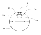
- FIG. 1 is a perspective view showing a transducer 1 of a hearing device according to an embodiment of the invention. 2 is a side view showing the vibrator 1, FIG. 3 is a bottom view showing the vibrator 1, and FIG. 4 is a rear view showing the vibrator 1. FIG.
- the case 2 of the vibrator 1 is composed of an upper case 2a and a lower case 2b.
- the upper case 2a and the lower case 2b are fixed to each other with an adhesive or the like.
- a projecting portion 2c is formed on the upper case 2a.
- the case 2 is made of resin (for example, ABS resin) or the like.
- FIG. 8 is a side view showing a state in which the cable 12 is connected to the vibrator 1.
- the surface of the case 2 excluding the projecting portion 2c is a curved surface.
- the portion of the case 2 excluding the projecting portion 2c has a spherical or nearly spherical shape.
- Spherical includes not only a perfectly spherical shape but also a substantially spherical shape within a certain error range.
- the vertical interval W2 between the projecting portions 2c is less than or equal to half the interval W3 from the lower end to the upper end of the upper case 2a.
- the projecting portion 2c extends in a tangential direction of the upper case 2, for example.
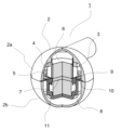
- FIG. 5 is a diagram (partial cross-sectional view with part of the transducer 1 cut away) showing the internal structure of the transducer 1 of the hearing device according to the embodiment of the present invention.
- FIG. 6 is an exploded perspective view of the transducer 1 of the hearing device according to the embodiment of the invention.
- a coil bobbin 4 , a coil 5 , magnets (first magnet 6 and second magnet 8 ), top plate 7 , frame 9 , damper 10 , yoke 11 and substrate 3 are housed in case 2 .
- a coil 5 is wound around the outside of the coil bobbin 4 .
- the coil bobbin 4 is long in the vertical direction, and the upper end of the coil bobbin 4 is in contact with the inner surface of the case 2 (upper case 2a).
- An electrical signal (such as an audio signal) is input to the coil 5 .
- the coil bobbin 4 is made of kraft paper or the like, and the coil 5 is made of copper or the like.
- the substrate 3 is attached to the inner surface of the case 2 (upper case 2a).
- a cable 12 (FIG. 8) is connected to the substrate 3, and a terminal side (not shown) of the coil 5 or wiring (not shown) connected to the coil 5 is connected.
- the cable 12 can be easily connected to the board 3. Further, the coil bobbin 4 is formed vertically so that its upper end abuts against the substrate 3 and the inner surface of the case 2 (upper case 2a). Wiring (not shown) can be easily connected to the substrate 3 .
- the magnets include a first magnet 6 and a second magnet 8 .
- Neodymium magnets for example, are used for the first magnet 6 and the second magnet 8 .
- the top plate 7 is arranged inside the coil bobbin 4 .
- a first magnet 6 is arranged on top plate 7 .
- a second magnet 8 is arranged under the top plate 7 .
- Iron SPCC or the like is used for the top plate 7, for example.
- the yoke 11 is open on the upper end side and has a bottom portion and a peripheral wall portion.
- the shape of the bottom inside the yoke 11 corresponds to the shape of the bottom end of the second magnet 8 so that the bottom end of the second magnet 8 is fixed inside the yoke 11 . Therefore, positioning of the second magnet 8 is facilitated.
- the yoke 11 is made of a soft magnetic material (such as SPCC).
- At least part of the coil bobbin 4 is arranged inside the yoke 11 .
- the outer edge of the damper 10 is fixed to the case 2 and sandwiched between the upper case 2a and the lower case 2b. That is, the outer edge of the damper 10 is sandwiched between the upper case 2a and the lower case 2b. A lower surface of the inner edge portion of the damper 10 is in contact with the upper end of the peripheral wall portion of the yoke 11 .
- the damper 10 is made of stainless steel, for example. As shown in FIG. 7, the damper 10 is formed with a through hole 10a penetrating vertically. A plurality of notches 10b are formed in the periphery of the damper 10. As shown in FIG.
- a plurality of concave portions 2e are formed in the upper case 2a, and a plurality of convex portions 2f are formed in the lower case 2b.
- the concave portion 2e and the convex portion 2f are combined at the notch 10b.
- the damper 10 is attached between the upper case 2a and the lower case 2b.
- the frame 9 fixes the damper 10 to the yoke 11. Specifically, the frame 9 is crimped and fixed to the damper 10 and the yoke 11 so as to contact the upper surface of the inner edge of the damper 10 and the inner surface of the peripheral wall of the yoke 11 .
- the frame 9 is made of a soft magnetic material (such as SPCC [steel plate cold commercial]).
- the damper 10 is fixed to the yoke 11 with an adhesive or the like (without using the frame 9), the fixing between the damper 10 and the yoke 11 is unstable. However, since the damper 10 is fixed to the yoke 11 using the frame 9, the damper 10 and the yoke 11 are easily fixed. That is, fixing the damper 10 and the yoke 11 using such a frame 9 is suitable for mass production.
- the damper 10 supports the yoke 11 by fixing the damper 10 to the yoke 11 by the frame 9 .
- the yoke 11 is suspended inside the case 2 by the damper 10 and the frame 9 . That is, the yoke 11 is separated from the inner surface of the case 2 .
- the yoke 11 is separated from the inner surface of the case 2, and such problems can be avoided.
- At least a part of the peripheral wall portions of the frame 9 and the yoke 11 faces the coil 5 .
- a soft magnetic material such as SPCC
- the case has a hole, sound leaks through the hole when the vibrator vibrates. If it is desirable to prevent sound leakage, it is conceivable to seal the case.
- case 2 may be sealed.
- a closing member (not shown) may be used to close the wiring hole 2d.
- the case is sealed and the diaphragm (damper, etc.) inside the case is formed in a shape without holes, it is difficult for vibration to occur. Especially if the case is small, the diaphragm will be difficult to move due to the air pressure inside the case.
- the space inside the case is divided into an upper space and a lower space by the diaphragm. For example, even if the diaphragm tries to move downward, the air in the lower space cannot move to the upper space. Therefore, the diaphragm cannot vibrate, or the amplitude of vibration of the diaphragm becomes small.
- the damper 10 is formed with a through hole 10a.
- the air above the damper 10 can move to the lower side of the damper 10 through the through holes 10a.
- the air below the damper 10 can move to the upper side of the damper 10 through the through holes 10a. Air movement within case 2 is unrestricted.
- the damper 10 can vibrate greatly not only when the case 2 is not sealed but also when the inside of the case 2 is a closed space. Therefore, even if the case 2 is small and sealed, the damper 10 can vibrate greatly.
- the damper 10 can vibrate greatly, so the case 2 can vibrate sufficiently. Therefore, sufficient vibration can be transmitted to the user of the vibrator 1 .
- the vibration of the damper or yoke causes the case to vibrate.
- the vibration is transmitted to the user and the user perceives the sound.
- the case vibrates the air around the case vibrates and air conduction sound is generated.
- the surface area is small and air-conducted noise can be suppressed. Therefore, it is possible to suppress leakage of air-conducted sound to the surroundings of the user while transmitting vibration to the user.
- the damper 10 may be made of Liquid Metal.
- the damper 10 may be damaged due to repeated vibrations. Although Liquidmetal is a metal, it has elasticity and is resistant to fatigue damage. When the damper 10 is made of Liquid Metal, the damper 10 can be used for a long time.
- the damper 10 is arranged in the center of the case 2 in the vertical direction.
- the case 2 can be made spherical or nearly spherical without increasing the size of the case 2. - ⁇ Note that the "center" includes not only the perfect center but also the substantial center within a certain error range.
- the shape of the case may be any other shape, and may not be spherical or nearly spherical like case 2 .
- FIG. 9 is a perspective view showing another shape example of the vibrator
- FIG. 10 is a perspective view showing still another shape example of the vibrator.
- Case 13 instead of Case 13 (FIG. 9) or Case 14 (FIG. 10) may be used instead of Case 2, instead of Case 2, the shapes of various parts such as dampers or yokes are appropriately changed so as to correspond to the shape of the case.
- the oscillator 1 may be used as a cartilage conduction oscillator. Therefore, the hearing device of the present invention preferably has the above transducer 1 as a cartilage conduction transducer for transmitting sound signals to the ear cartilage.
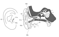
- FIG. 11 is an anatomical drawing of the ear.
- the above-described cartilage conduction makes it possible to hear sound by vibrating the tragus X2a and the auricular cartilage X2b, which are lighter. Very little drive energy is required.
- FIG. 12 is a graph showing an example of measured data showing the effect of cartilage conduction.
- This graph shows the inside of the external auditory canal 1 cm behind the entrance of the external auditory canal when the outer wall surface of the vibrator vibrating by the cartilage conduction vibration source is brought into contact with at least a part of the ear cartilage around the entrance of the external auditory canal without contacting the helix. It shows sound pressure in relation to frequency.
- the vertical axis of this graph is the sound pressure (dBSPL), and the horizontal axis is the frequency (Hz) on a logarithmic scale.
- this graph shows the effect of the contact pressure between the outer wall surface of the vibrator and the ear cartilage around the entrance of the ear canal on the sound pressure in the ear canal.
- the solid line represents the sound pressure at a contact pressure of 10 weight grams
- the dashed line represents the sound pressure at a contact pressure of 250 weight grams
- the external auditory canal is closed by further increasing the contact pressure.
- the two-dot chain line shows the sound pressure in the state where the contact pressure is 500 weight grams.
- the sound pressure increases from no contact to contact with a contact pressure of 10 grams force, further increases with an increase in contact pressure to 250 force grams, and from this state further increases the contact pressure to 500 force grams. This further increases the sound pressure.
- the distance of 1 cm from the entrance of the ear canal is higher than in the non-contact state. It can be seen that the sound pressure in the ear canal has increased by at least 10 dB in the main frequency band of sound (500 Hz to 2300 Hz).
- the necessary sound pressure can be obtained by transmitting the vibration of the cartilage conduction vibration source to the ear cartilage through contact, even without the mechanism for generating air-conducted sound (for example, the diaphragm of normal earphones).
- the vibrating body since the vibrating body is brought into contact with the ear cartilage around the entrance of the ear canal, it is possible to hear the sound from the vibrator without blocking the ear canal while keeping the ear canal open, and at the same time hearing the sound of the external world. It can be seen that comfortable wearing without a feeling of blockage is possible.
- the external auditory canal is closed by bringing the outer wall surface of the vibrating body into contact with at least a part of the ear cartilage more strongly (in the actual measurement of this figure, the outer wall surface of the vibrating body is pressed from the outside of the tragus).
- the ear canal is closed by bending the tragus)
- the sound pressure in the ear canal 1 cm behind the entrance of the ear canal is higher than that in the non-contact state in the main frequency band of sound (300 Hz to 1800 Hz).
- This indicates a large sound pressure enhancement effect due to the addition of the external auditory canal closing effect (compare the non-contact state shown by the solid line and the external auditory canal closed state shown by the two-dot chain line).
- the measurements in this graph are in a state where the output of the cartilage conduction vibration source is not changed.
- the measurement in this graph is a state in which the outer wall surface of the vibrating body is in contact with the outside of the tragus. I'm going with
- the measurement in the state where the ear canal is closed in this graph is performed by creating a state in which the ear canal is closed by pressing the tragus more strongly from the outside so that the tragus folds back as described above. .
- this graph is just an example, and there are individual differences if you look closely.
- this graph is measured in a state in which the outer wall surface of the vibrating body contacts only the outside of the tragus with a small area.
- the increase in sound pressure due to contact also depends on the contact area with the ear cartilage.
- the increase in sound pressure is further increased by contacting a wider ear cartilage portion.
- this graph shows that when the external auditory canal is closed, the contact pressure is increased by pressing the tragus from the outside to fold back the tragus. Similar results are obtained when the
- FIG. 13 is a diagram showing how the hearing device is used.
- the hearing device shown in FIG. 1 is used as, for example, a headphone such as a smartphone or a portable music player, a hearing aid, or a sound collector, and includes the aforementioned vibrator 1 as a cartilage vibrator.
- the invention disclosed in this specification can be used, for example, in smartphones, headphones such as portable music players, hearing aids, or sound collectors.
Abstract
This vibrator (1) comprises: a yoke (11) which has an open upper end side and has a bottom surface section and a peripheral wall section; a coil bobbin (4) of which at least a portion is disposed inside the yoke (11); a coil (5) wound on the outer side of the coil bobbin (4); magnets (6, 8) disposed inside the coil bobbin (4); a damper (10) which supports the yoke (11); a frame (9) which fixes the damper (10) to the yoke (11); and a case 2 which accommodates the yoke (11), the coil bobbin (4), the coil (5), the magnets (6, 8), the damper (10), and the frame (9). An outer edge section of the damper (10) is fixed to the case (2). A lower surface of an inner edge section of the damper (10) is in contact with an upper end of the peripheral wall section of the yoke (11). The frame (9) is caulked and fixed to the damper (10) and the yoke (11) so as to be in contact with each of the upper surface of the inner edge section of the damper (10) and the inner surface of the peripheral wall section of the yoke (11).
Description
本発明は、振動子及び聴取装置に関する。
The present invention relates to transducers and hearing devices.
従来、振動を対象物に伝達して、音を認識できるようにした機器、例えば、骨伝導デバイス、骨伝導スピーカ、又は、骨伝導振動子が様々提案されている(特許文献1から特許文献5)。
Conventionally, various proposals have been made for equipment that transmits vibration to an object so that sound can be recognized, such as a bone conduction device, a bone conduction speaker, or a bone conduction vibrator (Patent Documents 1 to 5). ).
しかしながらこれらの機器に関しては、さらに検討すべき課題が多い。
However, there are many issues that should be further considered regarding these devices.
本発明の課題は、上記に鑑み、より有用な振動子及び聴取装置を提供することにある。
In view of the above, an object of the present invention is to provide a more useful vibrator and hearing device.
上記課題を達成するため、本発明の振動子は、上端側が開口し、底面部と周壁部を有するヨークと、少なくとも一部が前記ヨークの内側に配置されたコイルボビンと、前記コイルボビンの外側に巻きまわされたコイルと、少なくとも一部が前記コイルボビンの内側に配置されたマグネットと、前記ヨークを支持するダンパーと、前記ダンパーを前記ヨークに固定するフレームと、前記ヨーク、前記コイルボビン、前記コイル、前記マグネット、前記ダンパー及び前記フレームを収容するケースと、を有し、前記ダンパーの外縁部は、前記ケースに固定されており、前記ダンパーの内縁部の下面は、前記ヨークの前記周壁部の上端に当接しており、前記フレームは、前記ダンパーの前記内縁部の上面と前記ヨークの前記周壁部の内面にそれぞれ当接するように、前記ダンパーと前記ヨークにかしめ固定されている。
In order to achieve the above object, the vibrator of the present invention includes a yoke having an open top end, a bottom portion and a peripheral wall portion, a coil bobbin at least partially disposed inside the yoke, and a coil bobbin wound outside the coil bobbin. a wound coil, a magnet at least partially disposed inside the coil bobbin, a damper supporting the yoke, a frame fixing the damper to the yoke, the yoke, the coil bobbin, the coil, the a case that houses the magnet, the damper, and the frame; the outer edge of the damper is fixed to the case; The frame is caulked and fixed to the damper and the yoke so as to contact the upper surface of the inner edge portion of the damper and the inner surface of the peripheral wall portion of the yoke, respectively.
また、本発明では、前記コイルボビンの上端は、前記ケースの内面に当接する。
Also, in the present invention, the upper end of the coil bobbin contacts the inner surface of the case.
また、本発明では、前記コイルボビンの内側に配置されたトッププレートをさらに有し、前記マグネットは、第1のマグネットと第2のマグネットを含み、前記第1のマグネットは、前記トッププレートの上に配置されており、前記第2のマグネットは、前記トッププレートの下に配置されている。
Moreover, the present invention further includes a top plate disposed inside the coil bobbin, the magnet includes a first magnet and a second magnet, and the first magnet is on the top plate. A second magnet is positioned below the top plate.
また、本発明では、前記第2のマグネットの下端側を前記ヨークの内側で固定するように、前記ヨークの内側の下部の形状は、前記第2のマグネットの下端側の形状に対応している。
Further, in the present invention, the shape of the inner lower part of the yoke corresponds to the shape of the lower end of the second magnet so that the lower end of the second magnet is fixed inside the yoke. .
また、本発明では、前記フレーム及び前記ヨークは、軟磁性材料により形成されている。
Also, in the present invention, the frame and the yoke are made of a soft magnetic material.
また、本発明では、前記フレーム及び前記ヨークの前記周壁部は、少なくとも一部が前記コイルに対向する。
Further, in the present invention, at least a part of the peripheral wall portion of the frame and the yoke faces the coil.
また、本発明では、前記ダンパーは、上下方向に貫通する貫通孔を有する。
Also, in the present invention, the damper has a through-hole penetrating vertically.
また、本発明では、前記ケースは、上側ケースと下側ケースを含み、前記ダンパーの前記外縁部は、前記上側ケースと前記下側ケースとの間に挟持されている。
Also, in the present invention, the case includes an upper case and a lower case, and the outer edge portion of the damper is sandwiched between the upper case and the lower case.
また、本発明では、前記上側ケースは、ケーブルを通すための配線孔を有する。
Also, in the present invention, the upper case has a wiring hole for passing a cable.
また、本発明では、前記配線孔を塞ぐ閉塞部材を備え、前記ケースが密閉されている。
In addition, in the present invention, the case is hermetically sealed by including a closing member that closes the wiring hole.
本発明の聴取装置は、耳軟骨に音信号を伝達するための軟骨伝導振動子として、上記のいずれかの振動子を有する。
The hearing device of the present invention has any one of the above vibrators as a cartilage conduction vibrator for transmitting sound signals to the ear cartilage.
上記のように、本発明によれば、より有用な振動子及び聴取装置が提供される。
As described above, according to the present invention, a more useful transducer and hearing device are provided.
<振動子>
図1は、本発明の実施の形態に係る聴取装置の振動子1を示す斜視図である。図2は、振動子1を示す側面図であり、図3は振動子1を示す下面図であり、図4は、振動子1を示す背面図である。 <Vibrator>
FIG. 1 is a perspective view showing atransducer 1 of a hearing device according to an embodiment of the invention. 2 is a side view showing the vibrator 1, FIG. 3 is a bottom view showing the vibrator 1, and FIG. 4 is a rear view showing the vibrator 1. FIG.
図1は、本発明の実施の形態に係る聴取装置の振動子1を示す斜視図である。図2は、振動子1を示す側面図であり、図3は振動子1を示す下面図であり、図4は、振動子1を示す背面図である。 <Vibrator>
FIG. 1 is a perspective view showing a
振動子1のケース2は、上側ケース2aと下側ケース2bで構成されている。上側ケース2aと下側ケース2bは接着剤等で互いに固定される。上側ケース2aには突出部2cが形成されている。ケース2は樹脂(例えばABS樹脂)などで形成されている。
The case 2 of the vibrator 1 is composed of an upper case 2a and a lower case 2b. The upper case 2a and the lower case 2b are fixed to each other with an adhesive or the like. A projecting portion 2c is formed on the upper case 2a. The case 2 is made of resin (for example, ABS resin) or the like.
上側ケース2aの突出部2cは、ケーブル12を通すための配線孔2dを有する。図8は、振動子1にケーブル12が接続された状態を示す側面図である。
The projecting portion 2c of the upper case 2a has a wiring hole 2d for passing the cable 12 through. FIG. 8 is a side view showing a state in which the cable 12 is connected to the vibrator 1. FIG.
ケース2の突出部2cを除いた部分の表面は曲面である。図示に即して述べると、ケース2の突出部2cを除いいた部分は、球形又は球形に近い形状を有する。「球形」とは、完全な球形だけでなく、一定の誤差範囲内の実質的な球形も含む。振動子1が使用者の耳に装着されるとき、ケース2の下端から突出部2cまでの間隔W1の部分が耳に引っ掛けられる。振動子1を耳に安定的に装着するため、間隔W1が大きいことが好ましい。例えば、突出部2cの上下方向の間隔W2は、上側ケース2aの下端から上端までの間隔W3の1/2以下とすることが考えられる。また、突出部2cは、例えば、上側ケース2の接線方向に延びているとの好ましい。
The surface of the case 2 excluding the projecting portion 2c is a curved surface. Referring to the drawing, the portion of the case 2 excluding the projecting portion 2c has a spherical or nearly spherical shape. "Spherical" includes not only a perfectly spherical shape but also a substantially spherical shape within a certain error range. When the vibrator 1 is worn on the ear of the user, the portion of the interval W1 from the lower end of the case 2 to the projecting portion 2c is hooked on the ear. In order to stably wear the transducer 1 on the ear, it is preferable that the interval W1 is large. For example, it is conceivable that the vertical interval W2 between the projecting portions 2c is less than or equal to half the interval W3 from the lower end to the upper end of the upper case 2a. Moreover, it is preferable that the projecting portion 2c extends in a tangential direction of the upper case 2, for example.
図5は、本発明の実施の形態に係る聴取装置の振動子1の内部の構造を示す図(振動子1の一部を切り欠いた部分断面図)である。図6は、本発明の実施の形態に係る聴取装置の振動子1の分解斜視図である。
FIG. 5 is a diagram (partial cross-sectional view with part of the transducer 1 cut away) showing the internal structure of the transducer 1 of the hearing device according to the embodiment of the present invention. FIG. 6 is an exploded perspective view of the transducer 1 of the hearing device according to the embodiment of the invention.
コイルボビン4、コイル5、マグネット(第1のマグネット6、第2のマグネット8)、トッププレート7、フレーム9、ダンパー10、ヨーク11、基板3が、ケース2の中に収容されている。
A coil bobbin 4 , a coil 5 , magnets (first magnet 6 and second magnet 8 ), top plate 7 , frame 9 , damper 10 , yoke 11 and substrate 3 are housed in case 2 .
コイルボビン4の外側にはコイル5が巻きまわされている。コイルボビン4は上下方向に長く、コイルボビン4の上端は、ケース2(上側ケース2a)の内面に当接している。コイル5には電気信号(音声信号等)が入力される。コイルボビン4はクラフト紙などで形成され、コイル5は銅などで形成されている。
A coil 5 is wound around the outside of the coil bobbin 4 . The coil bobbin 4 is long in the vertical direction, and the upper end of the coil bobbin 4 is in contact with the inner surface of the case 2 (upper case 2a). An electrical signal (such as an audio signal) is input to the coil 5 . The coil bobbin 4 is made of kraft paper or the like, and the coil 5 is made of copper or the like.
また、基板3が、ケース2(上側ケース2a)の内面に取り付けられている。基板3には、ケーブル12(図8)が接続するとともに、コイル5の末端側(不図示)、あるいはコイル5に接続した配線(不図示)が接続される。
Also, the substrate 3 is attached to the inner surface of the case 2 (upper case 2a). A cable 12 (FIG. 8) is connected to the substrate 3, and a terminal side (not shown) of the coil 5 or wiring (not shown) connected to the coil 5 is connected.
基板3は配線孔2dに近いので、ケーブル12を基板3に容易に接続することができる。また、コイルボビン4は、その上端が基板3とケース2(上側ケース2a)の内面に当接するように縦長に形成されているので、コイル5の末端側(不図示)、あるいはコイル5に接続した配線(不図示)を基板3に容易に接続できる。
Since the board 3 is close to the wiring hole 2d, the cable 12 can be easily connected to the board 3. Further, the coil bobbin 4 is formed vertically so that its upper end abuts against the substrate 3 and the inner surface of the case 2 (upper case 2a). Wiring (not shown) can be easily connected to the substrate 3 .
マグネット(第1のマグネット6、第2のマグネット8)の少なくとも一部は、コイルボビン4の内側に配置されている。マグネットは、第1のマグネット6と第2のマグネット8を含む。第1のマグネット6と第2のマグネット8には、例えば、ネオジウム磁石が使用される。
At least part of the magnets (the first magnet 6 and the second magnet 8) are arranged inside the coil bobbin 4. The magnets include a first magnet 6 and a second magnet 8 . Neodymium magnets, for example, are used for the first magnet 6 and the second magnet 8 .
トッププレート7は、コイルボビン4の内側に配置されている。第1のマグネット6はトッププレート7の上に配置されている。第2のマグネット8はトッププレート7の下に配置されている。トッププレート7には、例えば、鉄(SPCCなど)が使用される。
The top plate 7 is arranged inside the coil bobbin 4 . A first magnet 6 is arranged on top plate 7 . A second magnet 8 is arranged under the top plate 7 . Iron (SPCC or the like) is used for the top plate 7, for example.
ヨーク11は、上端側が開口し、底面部と周壁部を有する。第2のマグネット8の下端側をヨーク11の内側で固定するように、ヨーク11の内側の下部の形状は、第2のマグネット8の下端側の形状に対応している。よって、第2のマグネット8の位置決めが容易になる。ヨーク11は、軟磁性材料(SPCCなど)により形成されている。
The yoke 11 is open on the upper end side and has a bottom portion and a peripheral wall portion. The shape of the bottom inside the yoke 11 corresponds to the shape of the bottom end of the second magnet 8 so that the bottom end of the second magnet 8 is fixed inside the yoke 11 . Therefore, positioning of the second magnet 8 is facilitated. The yoke 11 is made of a soft magnetic material (such as SPCC).
コイルボビン4の少なくとも一部は、ヨーク11の内側に配置されている。
At least part of the coil bobbin 4 is arranged inside the yoke 11 .
ダンパー10の外縁部は、ケース2に固定されており、上側ケース2aと下側ケース2bで挟まれている。すなわち、ダンパー10の外縁部は、上側ケース2aと下側ケース2bとの間に挟持されている。ダンパー10の内縁部の下面は、ヨーク11の周壁部の上端に当接している。ダンパー10は、例えば、ステンレスで形成されている。ダンパー10は、図7に示すように、上下方向に貫通する貫通孔10aが形成されている。ダンパー10の周部には複数の切り欠き10bが形成されている。上側ケース2aには複数の凹部2eが形成され、下側ケース2bには複数の凸部2fが形成されている。凹部2eと凸部2fが切り欠き10bで組み合う。その結果、ダンパー10が上側ケース2aと下側ケース2bとの間で取り付けられる。
The outer edge of the damper 10 is fixed to the case 2 and sandwiched between the upper case 2a and the lower case 2b. That is, the outer edge of the damper 10 is sandwiched between the upper case 2a and the lower case 2b. A lower surface of the inner edge portion of the damper 10 is in contact with the upper end of the peripheral wall portion of the yoke 11 . The damper 10 is made of stainless steel, for example. As shown in FIG. 7, the damper 10 is formed with a through hole 10a penetrating vertically. A plurality of notches 10b are formed in the periphery of the damper 10. As shown in FIG. A plurality of concave portions 2e are formed in the upper case 2a, and a plurality of convex portions 2f are formed in the lower case 2b. The concave portion 2e and the convex portion 2f are combined at the notch 10b. As a result, the damper 10 is attached between the upper case 2a and the lower case 2b.
フレーム9は、ダンパー10をヨーク11に固定する。具体的には、フレーム9は、ダンパー10の内縁部の上面と、ヨーク11の周壁部の内面にそれぞれ当接するように、ダンパー10とヨーク11にかしめ固定されている。フレーム9は、軟磁性材料(SPCC[steel plate cold commercial]など)により形成されている。
The frame 9 fixes the damper 10 to the yoke 11. Specifically, the frame 9 is crimped and fixed to the damper 10 and the yoke 11 so as to contact the upper surface of the inner edge of the damper 10 and the inner surface of the peripheral wall of the yoke 11 . The frame 9 is made of a soft magnetic material (such as SPCC [steel plate cold commercial]).
もし(フレーム9を用いずに)ダンパー10を接着剤等でヨーク11に固定すると、ダンパー10とヨーク11との固定は不安定である。しかし、フレーム9を用いてダンパー10をヨーク11に固定しているので、ダンパー10とヨーク11とを固定しやすくなる。すなわち、このようなフレーム9を用いたダンパー10とヨーク11との固定は、量産に適している。
If the damper 10 is fixed to the yoke 11 with an adhesive or the like (without using the frame 9), the fixing between the damper 10 and the yoke 11 is unstable. However, since the damper 10 is fixed to the yoke 11 using the frame 9, the damper 10 and the yoke 11 are easily fixed. That is, fixing the damper 10 and the yoke 11 using such a frame 9 is suitable for mass production.
また、フレーム9がダンパー10をヨーク11に固定することにより、ダンパー10はヨーク11を支持する。ヨーク11は、ダンパー10とフレーム9により、ケース2の内部で宙吊りになっている。すなわち、ヨーク11はケース2の内面から離れている。
Also, the damper 10 supports the yoke 11 by fixing the damper 10 to the yoke 11 by the frame 9 . The yoke 11 is suspended inside the case 2 by the damper 10 and the frame 9 . That is, the yoke 11 is separated from the inner surface of the case 2 .
ヨークをケースの内面に接着剤等で固定すると、振動が全帯域で感じられず、高域(例えば5kHz以降)しか聞こえない問題が発生することがあった。本実施形態では、ヨーク11がケース2の内面から離れており、そのような問題を避けることができる。
When the yoke was fixed to the inner surface of the case with adhesive, etc., there was a problem that vibration could not be felt in the entire band, and only high frequencies (for example, after 5 kHz) could be heard. In this embodiment, the yoke 11 is separated from the inner surface of the case 2, and such problems can be avoided.
また、フレーム9及びヨーク11の周壁部は、少なくとも一部がコイル5に対向する。この構成では、コイル5に磁束を集めやすい。特に、フレーム9及びヨーク11が、軟磁性材料(SPCCなど)で形成されることにより、コイル5に磁束を集めやすくなる。磁束が集まる(磁束密度が高くなる)と、振動の駆動力が大きくなり、振動を発生させやすくなる。
At least a part of the peripheral wall portions of the frame 9 and the yoke 11 faces the coil 5 . With this configuration, it is easy to collect the magnetic flux in the coil 5 . In particular, by forming the frame 9 and the yoke 11 from a soft magnetic material (such as SPCC), it becomes easier to collect the magnetic flux in the coil 5 . When the magnetic flux gathers (the magnetic flux density increases), the driving force of the vibration increases, making it easier to generate vibration.
なお、ケースに孔が設けられている場合、振動子が振動するときにケースの孔から音が漏れる。音漏れを防止することが好ましい場合には、ケースを密閉することが考えられる。
If the case has a hole, sound leaks through the hole when the vibrator vibrates. If it is desirable to prevent sound leakage, it is conceivable to seal the case.
そこで、ケース2は密閉されてもよい。ケース2が密閉される場合には、配線孔2dを塞ぐ閉塞部材(不図示)が使用されてもよい。
Therefore, case 2 may be sealed. When the case 2 is hermetically sealed, a closing member (not shown) may be used to close the wiring hole 2d.
しかし、ケースが密閉され、ケース内の振動板(ダンパー等)が孔の無い形状に形成されていると、振動を発生させにくい。特にケースが小さい場合、振動板は、ケース内の空気圧により、動きにくくなる。また、ケース内の空間は、振動板により、上の空間と、下の空間に分けられる。例えば、振動板が下に移動しようとしても、下の空間内の空気は上の空間に移動できない。それゆえ、振動板は振動することができないか、振動板の振動幅が小さくなる。
However, if the case is sealed and the diaphragm (damper, etc.) inside the case is formed in a shape without holes, it is difficult for vibration to occur. Especially if the case is small, the diaphragm will be difficult to move due to the air pressure inside the case. The space inside the case is divided into an upper space and a lower space by the diaphragm. For example, even if the diaphragm tries to move downward, the air in the lower space cannot move to the upper space. Therefore, the diaphragm cannot vibrate, or the amplitude of vibration of the diaphragm becomes small.
本実施形態では、ダンパー10には、貫通孔10aが形成されている。ダンパー10の上側にある空気は、貫通孔10aを通って、ダンパー10の下側に移動することができる。また、ダンパー10の下側にある空気は、貫通孔10aを通って、ダンパー10の上側に移動することができる。ケース2内の空気の移動は制限されていない。ケース2が密閉されていない場合だけでなく、ケース2内が密閉空間の場合でも、ダンパー10は大きく振動することができる。よって、ケース2が小さく、且つ、密閉された場合でも、ダンパー10は大きく振動することができる。
In this embodiment, the damper 10 is formed with a through hole 10a. The air above the damper 10 can move to the lower side of the damper 10 through the through holes 10a. Also, the air below the damper 10 can move to the upper side of the damper 10 through the through holes 10a. Air movement within case 2 is unrestricted. The damper 10 can vibrate greatly not only when the case 2 is not sealed but also when the inside of the case 2 is a closed space. Therefore, even if the case 2 is small and sealed, the damper 10 can vibrate greatly.
ケース2が密閉されていない場合だけでなく、ケース2が密閉された場合でも、ダンパー10が大きく振動できるので、ケース2は十分に振動することができる。よって、振動子1の使用者に十分な振動を伝えることができる。
Not only when the case 2 is not sealed, but also when the case 2 is sealed, the damper 10 can vibrate greatly, so the case 2 can vibrate sufficiently. Therefore, sufficient vibration can be transmitted to the user of the vibrator 1 .
ところで、ダンパー又はヨークが振動することにより、ケースが振動する。振動するケースが使用者に当接することにより、使用者に振動が伝わり、使用者が音を認識するようになる。一方、ケースが振動すると、ケースの周囲の空気を振動させ、気導音が生じる。ケース2の場合、表面積は小さく、気導音を抑制することができる。よって、使用者に振動を伝えつつ、使用者の周囲に気導音が漏れることを抑制することができる。
By the way, the vibration of the damper or yoke causes the case to vibrate. When the vibrating case comes into contact with the user, the vibration is transmitted to the user and the user perceives the sound. On the other hand, when the case vibrates, the air around the case vibrates and air conduction sound is generated. In case 2, the surface area is small and air-conducted noise can be suppressed. Therefore, it is possible to suppress leakage of air-conducted sound to the surroundings of the user while transmitting vibration to the user.
ケース2が密閉されている場合、水又は汗がケース2に入らない。密閉されたケースの使用は、防水の振動子に応用することができる。
When the case 2 is sealed, water or sweat does not enter the case 2. The use of a sealed case can be applied to waterproof oscillators.
ダンパー10はリキッドメタルで形成されてもよい。ダンパー10は、振動の繰り返しにより、破損のおそれがある。リキッドメタルは、金属ではあるものの、弾力を有し、疲労破損がしにくい。ダンパー10がリキッドメタルで形成されると、ダンパー10は長期間使用できる。
The damper 10 may be made of Liquid Metal. The damper 10 may be damaged due to repeated vibrations. Although Liquidmetal is a metal, it has elasticity and is resistant to fatigue damage. When the damper 10 is made of Liquid Metal, the damper 10 can be used for a long time.
なお、ダンパー10は、ケース2の上下方向の中央に配置される。ケース2のサイズを大きくしないで、ケース2を球形または球形に近い形にできる。なお、「中央」は、完全な中央だけでなく、一定の誤差範囲内の実質的な中央も含む。ケースの形状は、他の形状でもよく、ケース2のような球形または球形に近い形状でなくてもよい。図9は、振動子の別の形状の例を示す斜視図であり、図10は、振動子のさらに別の形状の例を示す斜視図である。例えば、ケース2の代わりに、ケース13(図9)あるいはケース14(図10)が使用されてもよい。ケース2の代わりに、他の形状のケースが使用される場合、ダンパー又はヨーク等の各種の部品の形状は、ケースの形状に対応するように適宜に変更される。
The damper 10 is arranged in the center of the case 2 in the vertical direction. The case 2 can be made spherical or nearly spherical without increasing the size of the case 2. - 特許庁Note that the "center" includes not only the perfect center but also the substantial center within a certain error range. The shape of the case may be any other shape, and may not be spherical or nearly spherical like case 2 . FIG. 9 is a perspective view showing another shape example of the vibrator, and FIG. 10 is a perspective view showing still another shape example of the vibrator. For example, instead of Case 2, Case 13 (FIG. 9) or Case 14 (FIG. 10) may be used. If a case of other shape is used instead of the case 2, the shapes of various parts such as dampers or yokes are appropriately changed so as to correspond to the shape of the case.
振動子1は軟骨伝導振動子として使用されてもよい。よって、本発明の聴取装置は、耳軟骨に音信号を伝達するための軟骨伝導振動子として、上記の振動子1を有するのが好ましい。
The oscillator 1 may be used as a cartilage conduction oscillator. Therefore, the hearing device of the present invention preferably has the above transducer 1 as a cartilage conduction transducer for transmitting sound signals to the ear cartilage.
<軟骨伝導>
次に、振動子1を備える聴取装置の聴取メカニズムについて、図11を参照しながら説明する。なお、図11は、耳の解剖図である。 <Cartilage conduction>
Next, the listening mechanism of the hearing device provided with thevibrator 1 will be described with reference to FIG. Note that FIG. 11 is an anatomical drawing of the ear.
次に、振動子1を備える聴取装置の聴取メカニズムについて、図11を参照しながら説明する。なお、図11は、耳の解剖図である。 <Cartilage conduction>
Next, the listening mechanism of the hearing device provided with the
耳鼻科医である本願発明者は、これまでも、外耳道口X1aの周囲を取り巻く耳介X2の軟骨組織、例えば、耳珠X2a、ないしは、耳介X2の裏側に分布する耳介軟骨X2b(特に、外耳道口X1aの近傍となる部位)に振動子を当てると、その振動が軟骨部外耳道X1b(=外耳道X1のうち、外耳道口X1aに近い手前側の約半分)に伝わり、軟骨部外耳道X1bの内側表面から生じる気導音(=音響振動による空気の疎密波)が骨部外耳道X1c(=外耳道X1のうち、鼓膜X3に近い奥側の約半分)を経て鼓膜X3に達することにより、音が聞こえるという新規な聴取メカニズム(=気導でも骨導でもない第3の聴取メカニズム、図11の太い実線矢印を参照)を世界で初めて発見し、これを軟骨伝導[cartilage conduction]と名付けて、携帯電話または補聴器などでの利用を提案している。
The inventor of the present application, who is an otolaryngologist, has so far investigated the cartilage tissue of the auricle X2 surrounding the external auditory canal X1a, for example, the tragus X2a, or the auricular cartilage X2b distributed on the back side of the auricle X2 (especially , a portion near the ear canal opening X1a), the vibration is transmitted to the cartilage external auditory canal X1b (=about half of the external auditory canal X1 on the front side near the external auditory canal X1a), and the cartilage external auditory canal X1b. Air-conducted sound generated from the inner surface (= compressional waves of the air due to acoustic vibration) passes through the bone external auditory canal X1c (=about half of the external auditory canal X1 on the far side near the eardrum X3) and reaches the eardrum X3, whereby sound is generated. He was the first in the world to discover a new hearing mechanism of hearing (= a third hearing mechanism that is neither air conduction nor bone conduction, see the thick solid arrow in Fig. 11). We suggest using it with a phone or a hearing aid.
上記の軟骨伝導であれば、重い前頭骨や側頭骨を振動させる従来の骨導と異なり、より軽い耳珠X2aや耳介軟骨X2bを振動させて音を聴取することができるので、振動子の駆動エネルギーが非常に小さくて済む。
Unlike the conventional bone conduction that vibrates the heavy frontal and temporal bones, the above-described cartilage conduction makes it possible to hear sound by vibrating the tragus X2a and the auricular cartilage X2b, which are lighter. Very little drive energy is required.
また、軟骨伝導では、従来の気導(=外耳道口X1aの外部から入ってくる気導音が鼓膜X3を振動させることにより音が聞こえる現象)と異なり、外耳道口X1aを指などで閉鎖したときに、外耳道X1の内部における音響エネルギーが増大して音が大きく聞こえるようになる現象(=外耳道閉鎖効果)が認められる。そのため、外耳道口X1aを塞ぐことにより、周囲の騒音が大きい環境下でも明瞭に音を聞くことができる。
In addition, in cartilage conduction, unlike the conventional air conduction (=a phenomenon in which air-conducted sound entering from the outside of the external auditory canal X1a vibrates the eardrum X3, sound is heard), when the external auditory canal X1a is closed with a finger or the like, , a phenomenon (=external auditory canal closing effect) is observed in which the acoustic energy inside the external auditory canal X1 increases and the sound becomes louder. Therefore, by closing the ear canal X1a, the sound can be heard clearly even in an environment where the surrounding noise is loud.
図12は、軟骨伝導の効果を示す実測データの一例を示すグラフである。本グラフは、軟骨伝導振動源により振動する振動体の外壁表面を耳輪への接触なしに外耳道入口部周辺の耳軟骨の少なくとも一部に接触させたときの外耳道入口部から1cm奥の外耳道内の音圧を周波数との関係で示すものである。
FIG. 12 is a graph showing an example of measured data showing the effect of cartilage conduction. This graph shows the inside of the external auditory canal 1 cm behind the entrance of the external auditory canal when the outer wall surface of the vibrator vibrating by the cartilage conduction vibration source is brought into contact with at least a part of the ear cartilage around the entrance of the external auditory canal without contacting the helix. It shows sound pressure in relation to frequency.
なお、本グラフの縦軸は音圧(dBSPL)であり、横軸は対数目盛の周波数(Hz)である。また、本グラフには、振動体の外壁表面と外耳道入口部周辺の耳軟骨との接触圧が外耳道内の音圧に与える影響を示すべく、非接触状態(=振動体の外壁表面から発生する気導音のみが聞こえる状態)の音圧を実線で、接触圧10重量グラムにおける音圧を破線で、接触圧250重量グラムにおける音圧を一点鎖線で、接触圧のさらなる増加により外耳道が閉鎖された状態(接触圧500重量グラム)における音圧を二点鎖線で、それぞれ図示している。
The vertical axis of this graph is the sound pressure (dBSPL), and the horizontal axis is the frequency (Hz) on a logarithmic scale. In addition, this graph shows the effect of the contact pressure between the outer wall surface of the vibrator and the ear cartilage around the entrance of the ear canal on the sound pressure in the ear canal. The solid line represents the sound pressure at a contact pressure of 10 weight grams, the dashed line represents the sound pressure at a contact pressure of 250 weight grams, and the external auditory canal is closed by further increasing the contact pressure. The two-dot chain line shows the sound pressure in the state where the contact pressure is 500 weight grams.
図示のように、音圧は非接触状態から接触圧10重量グラムでの接触により増加し、さらに250重量グラムへの接触圧増加により増加し、この状態からさらに500重量グラムに接触圧を増加させることで、音圧がさらに増加する。
As shown, the sound pressure increases from no contact to contact with a contact pressure of 10 grams force, further increases with an increase in contact pressure to 250 force grams, and from this state further increases the contact pressure to 500 force grams. This further increases the sound pressure.
本グラフから明らかなように、振動体の外壁表面を耳輪への接触なしに外耳道入口部周辺の耳軟骨の少なくとも一部に接触させたとき、非接触状態に比べ、外耳道入口部から1cm奥の外耳道内における音圧が音声の主要な周波数帯域(500Hz~2300Hz)において少なくとも10dB増加していることがわかる(実線で示す非接触状態と、一点鎖線で示す状態とを比較参照。)
As is clear from this graph, when the outer wall surface of the vibrating body is brought into contact with at least a part of the ear cartilage around the entrance of the ear canal without contacting the helix, the distance of 1 cm from the entrance of the ear canal is higher than in the non-contact state. It can be seen that the sound pressure in the ear canal has increased by at least 10 dB in the main frequency band of sound (500 Hz to 2300 Hz).
また、本グラフから明らかなように、振動体の外壁表面を耳輪への接触なしに外耳道入口部周辺の耳軟骨の少なくとも一部に接触させたとき、接触圧の変化によって外耳道入口部から1cm奥の外耳道内における音圧が音声の主要な周波数帯域(500Hz~2500Hz)において少なくとも5dB変化していることがわかる(破線で示すわずかな接触状態と一点鎖線で示す状態での接触状態とを比較参照。)
Moreover, as is clear from this graph, when the outer wall surface of the vibrating body is brought into contact with at least a part of the ear cartilage around the entrance of the external auditory canal without contacting the helix, the change in contact pressure changes the depth of 1 cm from the entrance of the external auditory canal. It can be seen that the sound pressure in the external auditory canal changes at least 5 dB in the main frequency band of sound (500 Hz to 2500 Hz) (compare the slight contact state shown by the dashed line and the contact state shown by the dashed line) .)
以上から、気導音の発生機構(例えば通常イヤホンの振動板)がなくても、軟骨伝導振動源の振動を接触により耳軟骨に伝達することで必要な音圧が得られることがわかる。また、振動体を外耳道入口部周辺の耳軟骨に接触させて聞くので、外耳道は開放されたまま外耳道を塞ぐことなく振動子からの音を聞くと同時に外界の音を聞くことができ、外耳道の閉塞感のない快適な装着が可能となることがわかる。
From the above, it can be seen that the necessary sound pressure can be obtained by transmitting the vibration of the cartilage conduction vibration source to the ear cartilage through contact, even without the mechanism for generating air-conducted sound (for example, the diaphragm of normal earphones). In addition, since the vibrating body is brought into contact with the ear cartilage around the entrance of the ear canal, it is possible to hear the sound from the vibrator without blocking the ear canal while keeping the ear canal open, and at the same time hearing the sound of the external world. It can be seen that comfortable wearing without a feeling of blockage is possible.
さらに、本グラフから明らかなように、振動体の外壁表面を耳軟骨の少なくとも一部により強く接触させることにより外耳道を閉鎖(本図の実測では、耳珠の外側から振動体の外壁表面を押し付け、耳珠が折れ曲がることにより外耳道を閉鎖する状態にして測定)したとき、非接触状態に比べ、外耳道入口部から1cm奥の外耳道内における音圧が音声の主要な周波数帯域(300Hz~1800Hz)において少なくとも20dB増加していることがわかる。これは外耳道閉鎖効果が加わることによる大きい音圧増強効果を示すものである(実線で示す非接触状態と、二点鎖線で示す外耳道が閉鎖された状態とを比較参照。)
Furthermore, as is clear from this graph, the external auditory canal is closed by bringing the outer wall surface of the vibrating body into contact with at least a part of the ear cartilage more strongly (in the actual measurement of this figure, the outer wall surface of the vibrating body is pressed from the outside of the tragus). , the ear canal is closed by bending the tragus), the sound pressure in the ear canal 1 cm behind the entrance of the ear canal is higher than that in the non-contact state in the main frequency band of sound (300 Hz to 1800 Hz). It can be seen that there is an increase of at least 20 dB. This indicates a large sound pressure enhancement effect due to the addition of the external auditory canal closing effect (compare the non-contact state shown by the solid line and the external auditory canal closed state shown by the two-dot chain line).
なお、本グラフにおける測定は、すべて軟骨伝導振動源の出力を変化させない状態におけるものである。また 耳輪への接触なしに振動体の外壁表面を外耳道入口部周辺の耳軟骨の少なくとも一部に接触させる状態として、本グラフにおける測定は、振動体の外壁表面を耳珠の外側から接触させる状態で行っている。また、本グラフにおける外耳道が閉鎖された状態での測定は、上記のように耳珠を外側からより強く押圧することで耳珠が折り返ることにより外耳道を閉鎖する状態を作ることにより行っている。
It should be noted that all the measurements in this graph are in a state where the output of the cartilage conduction vibration source is not changed. In addition, as a state in which the outer wall surface of the vibrating body is in contact with at least a part of the ear cartilage around the entrance of the external auditory canal without contacting the helix, the measurement in this graph is a state in which the outer wall surface of the vibrating body is in contact with the outside of the tragus. I'm going with In addition, the measurement in the state where the ear canal is closed in this graph is performed by creating a state in which the ear canal is closed by pressing the tragus more strongly from the outside so that the tragus folds back as described above. .
また、本グラフは、あくまでも一例であって、細かく見れば個人差がある。また、本グラフは、現象の単純化及び標準化のために振動体の外壁表面を耳珠の外側に限って小さい面積で接触させる状態にて測定を行っている。
Also, this graph is just an example, and there are individual differences if you look closely. In addition, in order to simplify and standardize the phenomenon, this graph is measured in a state in which the outer wall surface of the vibrating body contacts only the outside of the tragus with a small area.
しかしながら、接触による音圧の増加は、耳軟骨との接触面積にも依存し、耳輪への接触なしに振動体の外壁表面を外耳道入口部周辺の耳軟骨に接触させる場合、外耳道入口部周辺のより広い耳軟骨部分に接触させれば音圧の増加はさらに高まる。以上のことを考慮すれば、本グラフに示した数値は、軟骨伝導を利用した構成を示す一般性を持つものであって、不特定多数の被験者による再現性のあるものである。
However, the increase in sound pressure due to contact also depends on the contact area with the ear cartilage. The increase in sound pressure is further increased by contacting a wider ear cartilage portion. Considering the above, the numerical values shown in this graph have generality indicating the configuration using cartilage conduction, and are reproducible by an unspecified number of subjects.
さらに、本グラフは、外耳道を閉鎖する際に耳珠を外側から押圧することで接触圧を増して耳珠を折り返すことによるものであるが、振動体の外壁表面を外耳道入口部に押し入れて外耳道を閉鎖した場合にも同様の結果が得られる。
Furthermore, this graph shows that when the external auditory canal is closed, the contact pressure is increased by pressing the tragus from the outside to fold back the tragus. Similar results are obtained when the
<聴取装置の使用態様>
図13は、聴取装置の使用態様を示す図である。本図の聴取装置は、例えば、スマートフォン若しくは携帯音楽プレイヤーなどのヘッドフォン、補聴器、又は、集音器として利用されるものであり、軟骨振動子として先出の振動子1を備えている。 <How to use the hearing device>
FIG. 13 is a diagram showing how the hearing device is used. The hearing device shown in FIG. 1 is used as, for example, a headphone such as a smartphone or a portable music player, a hearing aid, or a sound collector, and includes theaforementioned vibrator 1 as a cartilage vibrator.
図13は、聴取装置の使用態様を示す図である。本図の聴取装置は、例えば、スマートフォン若しくは携帯音楽プレイヤーなどのヘッドフォン、補聴器、又は、集音器として利用されるものであり、軟骨振動子として先出の振動子1を備えている。 <How to use the hearing device>
FIG. 13 is a diagram showing how the hearing device is used. The hearing device shown in FIG. 1 is used as, for example, a headphone such as a smartphone or a portable music player, a hearing aid, or a sound collector, and includes the
振動子1は、音信号(=音の情報を含む電気信号)に応じた振動を生成し、外耳道口X1aの周囲を取り巻く軟骨組織に伝達する。本図に即して述べると、振動子1は、耳珠X2aと対耳珠X2cに挟まれた珠間切痕X2d(=耳甲介腔の下部)に収まる大きさの球状に形成されており、振動子1が当接する軟骨組織に振動を伝達することで、使用者に音を聴取せしめる。
The vibrator 1 generates vibrations according to sound signals (=electrical signals containing sound information) and transmits them to the cartilage tissue surrounding the ear canal X1a. Referring to this figure, the vibrator 1 is formed in a spherical shape that is sized to fit in the intertragic notch X2d (=lower part of the conchal cavity) sandwiched between the tragus X2a and the antitragus X2c. , the vibration is transmitted to the cartilage tissue with which the vibrator 1 abuts, thereby allowing the user to hear the sound.
このような使用態様であれば、安定かつ極めて自然な聴取を実現することができる。
With such a mode of use, it is possible to achieve stable and extremely natural listening.
<その他の変形例>
なお、本明細書中に開示されている種々の技術的特徴は、上記実施形態のほか、その技術的創作の主旨を逸脱しない範囲で種々の変更を加えることが可能である。すなわち、上記実施形態は、全ての点で例示であって制限的なものではないと考えられるべきであり、本発明の技術的範囲は、特許請求の範囲の記載により規定されるものであって、特許請求の範囲と均等の意味及び範囲内に属する全ての変更が含まれると理解されるべきである。 <Other Modifications>
In addition to the above embodiments, the various technical features disclosed in this specification can be modified in various ways without departing from the gist of the technical creation. That is, the above embodiments should be considered as examples and not restrictive in all respects, and the technical scope of the present invention is defined by the description of the claims. , all changes that come within the meaning and range of equivalency of the claims are to be understood.
本明細書中に開示されている発明は、例えば、スマートフォン又は携帯音楽プレイヤーなどのヘッドフォン、若しくは、補聴器又は集音器に利用することが可能である。
The invention disclosed in this specification can be used, for example, in smartphones, headphones such as portable music players, hearing aids, or sound collectors.
1…振動子、2・13・14…ケース、3…基板、4…コイルボビン、5…コイル、6…マグネット(第1のマグネット)、7…トッププレート、8…マグネット(第2のマグネット)、9…フレーム、10…ダンパー、10a…貫通孔、11…ヨーク、12…ケーブル、X1…外耳道、X1a…外耳道口、X1b…軟骨部外耳道、X1c…骨部外耳道X1c、X2…耳介、X2a…耳珠、X2b…耳介裏側の耳介軟骨、X2c…対耳珠、X2d…珠間切痕、X3…鼓膜
DESCRIPTION OF SYMBOLS 1... Vibrator, 2, 13, 14... Case, 3... Substrate, 4... Coil bobbin, 5... Coil, 6... Magnet (first magnet), 7... Top plate, 8... Magnet (second magnet), 9 Frame 10 Damper 10a Through hole 11 Yoke 12 Cable X1 External auditory canal X1a External auditory canal opening X1b Cartilage external auditory canal X1c Bone external auditory canal X1c, X2 Auricle X2a Tragus, X2b: auricle cartilage behind the auricle, X2c: antitragus, X2d: intertragic notch, X3: tympanic membrane
Claims (11)
- 上端側が開口し、底面部と周壁部を有するヨークと、
少なくとも一部が前記ヨークの内側に配置されたコイルボビンと、
前記コイルボビンの外側に巻きまわされたコイルと、
少なくとも一部が前記コイルボビンの内側に配置されたマグネットと、
前記ヨークを支持するダンパーと、
前記ダンパーを前記ヨークに固定するフレームと、
前記ヨーク、前記コイルボビン、前記コイル、前記マグネット、前記ダンパー及び前記フレームを収容するケースと、
を有し、
前記ダンパーの外縁部は、前記ケースに固定されており、
前記ダンパーの内縁部の下面は、前記ヨークの前記周壁部の上端に当接しており、
前記フレームは、前記ダンパーの前記内縁部の上面と前記ヨークの前記周壁部の内面にそれぞれ当接するように、前記ダンパーと前記ヨークにかしめ固定されている、振動子。 a yoke open at the upper end side and having a bottom portion and a peripheral wall portion;
a coil bobbin at least partially disposed inside the yoke;
a coil wound around the outside of the coil bobbin;
a magnet at least partially disposed inside the coil bobbin;
a damper that supports the yoke;
a frame that secures the damper to the yoke;
a case that houses the yoke, the coil bobbin, the coil, the magnet, the damper, and the frame;
has
An outer edge of the damper is fixed to the case,
a lower surface of the inner edge portion of the damper is in contact with an upper end of the peripheral wall portion of the yoke;
The vibrator, wherein the frame is crimped and fixed to the damper and the yoke so as to contact the upper surface of the inner edge portion of the damper and the inner surface of the peripheral wall portion of the yoke, respectively. - 前記コイルボビンの上端は、前記ケースの内面に当接する、請求項1に記載の振動子。 The vibrator according to claim 1, wherein the upper end of the coil bobbin contacts the inner surface of the case.
- 前記コイルボビンの内側に配置されたトッププレートをさらに有し、
前記マグネットは、第1のマグネットと第2のマグネットを含み、
前記第1のマグネットは、前記トッププレートの上に配置されており、
前記第2のマグネットは、前記トッププレートの下に配置されている、請求項1または請求項2に記載の振動子。 further comprising a top plate disposed inside the coil bobbin;
the magnet includes a first magnet and a second magnet;
The first magnet is arranged on the top plate,
3. The vibrator according to claim 1, wherein said second magnet is arranged below said top plate. - 前記第2のマグネットの下端側を前記ヨークの内側で固定するように、前記ヨークの内側の下部の形状は、前記第2のマグネットの下端側の形状に対応している、請求項3に記載の振動子。 4. The configuration according to claim 3, wherein the shape of the bottom inside the yoke corresponds to the shape of the bottom end of the second magnet so that the bottom end of the second magnet is fixed inside the yoke. oscillator.
- 前記フレーム及び前記ヨークは、軟磁性材料により形成されている、請求項1~請求項4のいずれか一項に記載の振動子。 The vibrator according to any one of claims 1 to 4, wherein the frame and the yoke are made of a soft magnetic material.
- 前記フレーム及び前記ヨークの前記周壁部は、少なくとも一部が前記コイルに対向する、請求項5に記載の振動子。 6. The vibrator according to claim 5, wherein at least a part of said peripheral wall portion of said frame and said yoke faces said coil.
- 前記ダンパーは、上下方向に貫通する貫通孔を有する、請求項1~請求項6のいずれか一項に記載の振動子。 The vibrator according to any one of claims 1 to 6, wherein the damper has a through hole penetrating vertically.
- 前記ケースは、上側ケースと下側ケースを含み、
前記ダンパーの前記外縁部は、前記上側ケースと前記下側ケースとの間に挟持されている、請求項1~請求項7のいずれか一項に記載の振動子。 the case includes an upper case and a lower case;
8. The vibrator according to claim 1, wherein said outer edge of said damper is sandwiched between said upper case and said lower case. - 前記上側ケースは、ケーブルを通すための配線孔を有する、請求項8に記載の振動子。 The vibrator according to claim 8, wherein the upper case has a wiring hole for passing a cable.
- 前記配線孔を塞ぐ閉塞部材を備え、前記ケースが密閉されている、請求項9に記載の振動子。 The vibrator according to claim 9, comprising a closing member that closes the wiring hole, and the case is sealed.
- 耳軟骨に音信号を伝達するための軟骨伝導振動子として、請求項1~請求項10のいずれか一項に記載の振動子を有する、聴取装置。 A hearing device comprising the vibrator according to any one of claims 1 to 10 as a cartilage conduction vibrator for transmitting sound signals to the ear cartilage.
Priority Applications (2)
| Application Number | Priority Date | Filing Date | Title |
|---|---|---|---|
| JP2023551290A JPWO2023053958A1 (en) | 2021-10-01 | 2022-09-14 | |
| CN202280031848.3A CN117296336A (en) | 2021-10-01 | 2022-09-14 | Vibrator and listening device |
Applications Claiming Priority (2)
| Application Number | Priority Date | Filing Date | Title |
|---|---|---|---|
| JP2021162849 | 2021-10-01 | ||
| JP2021-162849 | 2021-10-01 |
Publications (1)
| Publication Number | Publication Date |
|---|---|
| WO2023053958A1 true WO2023053958A1 (en) | 2023-04-06 |
Family
ID=85782425
Family Applications (1)
| Application Number | Title | Priority Date | Filing Date |
|---|---|---|---|
| PCT/JP2022/034333 WO2023053958A1 (en) | 2021-10-01 | 2022-09-14 | Vibrator and listening device |
Country Status (3)
| Country | Link |
|---|---|
| JP (1) | JPWO2023053958A1 (en) |
| CN (1) | CN117296336A (en) |
| WO (1) | WO2023053958A1 (en) |
Citations (3)
| Publication number | Priority date | Publication date | Assignee | Title |
|---|---|---|---|---|
| WO2004006620A1 (en) * | 2002-07-04 | 2004-01-15 | Nec Tokin Corporation | Electroacoustic transducer |
| JP2006203709A (en) * | 2005-01-24 | 2006-08-03 | Citizen Electronics Co Ltd | Oscillator |
| WO2009133986A1 (en) * | 2008-05-01 | 2009-11-05 | Yea Il Electronics Co., Ltd. | Sensory signal output apparatus |
-
2022
- 2022-09-14 JP JP2023551290A patent/JPWO2023053958A1/ja active Pending
- 2022-09-14 WO PCT/JP2022/034333 patent/WO2023053958A1/en active Application Filing
- 2022-09-14 CN CN202280031848.3A patent/CN117296336A/en active Pending
Patent Citations (3)
| Publication number | Priority date | Publication date | Assignee | Title |
|---|---|---|---|---|
| WO2004006620A1 (en) * | 2002-07-04 | 2004-01-15 | Nec Tokin Corporation | Electroacoustic transducer |
| JP2006203709A (en) * | 2005-01-24 | 2006-08-03 | Citizen Electronics Co Ltd | Oscillator |
| WO2009133986A1 (en) * | 2008-05-01 | 2009-11-05 | Yea Il Electronics Co., Ltd. | Sensory signal output apparatus |
Also Published As
| Publication number | Publication date |
|---|---|
| CN117296336A (en) | 2023-12-26 |
| JPWO2023053958A1 (en) | 2023-04-06 |
Similar Documents
| Publication | Publication Date | Title |
|---|---|---|
| KR101484650B1 (en) | bone conduction speaker module | |
| WO2015198683A1 (en) | Bone conduction speaker | |
| JP6515392B2 (en) | Voice vibration generator | |
| KR100934273B1 (en) | Vibrative type ear phone | |
| WO2021063113A1 (en) | Bone conduction loudspeaker, bone conduction earphone, and bone conduction hearing aid | |
| KR20050106482A (en) | Bone conduction device | |
| KR101092958B1 (en) | Earset | |
| JP2010087810A (en) | Ear canal type bone conduction receiver | |
| JP5498515B2 (en) | earphone | |
| WO2021063112A1 (en) | Bone conduction loudspeaker, bone conduction headphones and bone conduction hearing aid | |
| JP2008270879A (en) | Receiver | |
| CN113286232A (en) | Loudspeaker structure | |
| JP2011119913A (en) | Hybrid type speaker unit and hybrid type speaker | |
| JP3045032B2 (en) | headphone | |
| JP2006174432A (en) | Bone conduction speaker, headphone, headrest, and pillow using the same | |
| JP5849296B1 (en) | Sealed earphone with communication part | |
| WO2023053958A1 (en) | Vibrator and listening device | |
| JP6006686B2 (en) | Speaker device | |
| WO2005006809A1 (en) | Piezoelectric vibration generator and vibratory sound transmitter | |
| TW202135538A (en) | Loudspeaker structure | |
| WO2023097740A1 (en) | Compound loudspeaker and sound production apparatus | |
| KR100931022B1 (en) | Earphone | |
| KR20080015185A (en) | Bone conductive ear phone | |
| US20240098422A1 (en) | Bone conduction loudspeaker | |
| JP2020014069A (en) | Speaker curved diaphragm |
Legal Events
| Date | Code | Title | Description |
|---|---|---|---|
| 121 | Ep: the epo has been informed by wipo that ep was designated in this application |
Ref document number: 22875829 Country of ref document: EP Kind code of ref document: A1 |
|
| WWE | Wipo information: entry into national phase |
Ref document number: 18288976 Country of ref document: US Ref document number: 2023551290 Country of ref document: JP |