WO2023042401A1 - Image presentation device, image presentation method, and program - Google Patents
Image presentation device, image presentation method, and program Download PDFInfo
- Publication number
- WO2023042401A1 WO2023042401A1 PCT/JP2021/034432 JP2021034432W WO2023042401A1 WO 2023042401 A1 WO2023042401 A1 WO 2023042401A1 JP 2021034432 W JP2021034432 W JP 2021034432W WO 2023042401 A1 WO2023042401 A1 WO 2023042401A1
- Authority
- WO
- WIPO (PCT)
- Prior art keywords
- image
- images
- effect
- user
- presentation device
- Prior art date
Links
- 238000000034 method Methods 0.000 title claims abstract description 21
- 230000000694 effects Effects 0.000 claims abstract description 80
- 230000002194 synthesizing effect Effects 0.000 claims description 14
- 238000010586 diagram Methods 0.000 description 13
- 239000002131 composite material Substances 0.000 description 7
- 230000006870 function Effects 0.000 description 4
- 230000015654 memory Effects 0.000 description 3
- 238000004891 communication Methods 0.000 description 2
- 238000012986 modification Methods 0.000 description 2
- 230000004048 modification Effects 0.000 description 2
- 235000010724 Wisteria floribunda Nutrition 0.000 description 1
- 238000005516 engineering process Methods 0.000 description 1
- 230000004927 fusion Effects 0.000 description 1
- 239000007787 solid Substances 0.000 description 1
- 238000006467 substitution reaction Methods 0.000 description 1
Images


Classifications
-
- H—ELECTRICITY
- H04—ELECTRIC COMMUNICATION TECHNIQUE
- H04N—PICTORIAL COMMUNICATION, e.g. TELEVISION
- H04N7/00—Television systems
- H04N7/18—Closed-circuit television [CCTV] systems, i.e. systems in which the video signal is not broadcast
Definitions
- the present disclosure relates to an image presentation device, an image presentation method, and a program.
- FIG. 10 is a block diagram showing a configuration example of a conventional image presentation device.
- the image capturing unit 11 creates a captured image a by capturing an image of the user
- the image processing unit 12 creates a processed image b by processing the captured image a with an effect.
- the image combining unit 14 creates a combined image d by combining the processed images b of a plurality of users, and presents the combined image d on the display device (display) 4 .
- Effect means to process sound or image and add some kind of special effect.
- Non-Patent Document 1 discloses a commemorative photography service provided at attractions such as theme parks and amusement parks. A service that combines and presents images of users of
- Non-Patent Document 2 describes a service for processing an image of a user using Kabuki kumadori. In addition to this, a service may be considered in which images of a plurality of surrounding users are combined and presented on a display device such as a large monitor.
- Fujifilm ⁇ The world only Fuji knows - Make the best memories of the theme park'', [online], [Searched August 26, 2021], Internet ⁇ URL: https://sp-jp.fujifilm.com /netprint/shiranai-sekai/sep_2017/> NTT realizes the fusion of Kabuki and the latest ICT technology at Niconico Chokaigi 2016 and Japan KABUKI Festival in Las Vegas 2016, [searched August 26, 2021], Internet ⁇ URL: https://group.ntt /jp/newsrelease/2017/04/19/160419a.html>
- the images that the user accesses include images of users other than himself/herself, there is a problem that it is a burden to find the image taken by the user himself/herself.
- An object of the present invention which has been made in view of such circumstances, is to alternately present an image processed with an effect and an image before processing when providing an image to the user, so that the user can: To reduce the burden of finding an image in which oneself is photographed from among a plurality of images.
- an image presentation device for presenting an image of a user, comprising: an image photographing unit for photographing images of a plurality of users; An image processing unit that processes an image using an effect, and an image combining unit that alternately switches between the photographed image and the processed image and displays the image on a display device.
- an image presentation method for presenting an image of a user, comprising the steps of photographing images of a plurality of users with an image presentation device; The step of processing the photographed image using an effect, and the step of alternately switching between the photographed images of the plurality of users and the processed images and displaying them on a display device are included.
- the computer according to the first embodiment is caused to function as the above image presentation device.
- the user can easily find the image in which he or she was shot from among the multiple images.
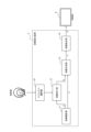
- FIG. 1 is a block diagram showing a configuration example of an image presentation device according to a first embodiment
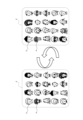
- FIG. It is an illustration of an image (photographed image) of a user. It is an illustration of an image (processed image) obtained by processing a photographed image using an effect.
- FIG. 4 is a schematic diagram showing an image (composite image) obtained by compositing a photographed image and a processed image; It is a schematic diagram showing an image (combined image) obtained by combining composite images of a plurality of users.
- 4 is a flow chart showing an example of an image presentation method executed by the image presentation device according to the first embodiment; It is a block diagram which shows the structural example of the image presentation apparatus which concerns on 2nd Embodiment.
- FIG. 9 is a flow chart showing an example of an image presentation method executed by the image presentation device according to the second embodiment.
- 1 is a block diagram showing a schematic configuration of a computer functioning as an image presentation device;
- FIG. It is a block diagram which shows the structural example of the conventional image presentation apparatus.
- FIG. 1 is a block diagram showing a configuration example of an image presentation device according to the first embodiment.
- the image presentation device 1 shown in FIG. 1 includes an image capturing section 11, an image processing section 12, an image synthesizing section 13, and an image combining section .
- the image presentation device 1 presents a user's image by alternately switching between an image processed by an effect and an image before processing.
- the image processing unit 12, the image synthesizing unit 13, and the image combining unit 14 constitute a control arithmetic circuit (controller).
- the control arithmetic circuit may be configured by dedicated hardware such as ASIC (Application Specific Integrated Circuit) or FPGA (Field-Programmable Gate Array), may be configured by a processor, or may be configured by including both may be
- ASIC Application Specific Integrated Circuit
- FPGA Field-Programmable Gate Array
- the image capturing unit 11 captures an image of the user.
- the image capturing unit 11 is a camera.
- FIG. 2 is an illustration of a photographed image of a user (hereinafter referred to as "photographed image a", “photographed image a", or "a”).
- the image capturing unit 11 outputs the captured image a to the image processing unit 12 and the image synthesizing unit 13 .
- the image processing unit 12 processes the captured image a using effects.
- the image processing unit 12 may use effects that the image presentation device 1 has in advance. If the image presentation device 1 does not have an effect, an effect image input from an external terminal or an effect indicated by an effect image specified by the user may be used.
- FIG. 3 is an illustration of an image obtained by processing the captured image a using effects (hereinafter referred to as “processed image b”, “processed image b” or “b”).
- the sunglasses s correspond to the effect image showing the effect, and an example is shown in which the effect image is superimposed on the captured image a as "processing".
- the image processing unit 12 outputs the processed image b to the image synthesizing unit 13 .
- the image synthesizing unit 13 synthesizes the captured image a input from the image capturing unit 11 and the processed image b input from the image processing unit 12 .
- FIG. 4 is a schematic diagram showing a synthesized image obtained by synthesizing a photographed image and a processed image (hereinafter referred to as "synthesized image c", “synthesized image c", or "c").
- the synthesized image c is composed of the captured image a and the processed image b.
- the image synthesizing unit 13 may generate a synthesized image c that is presented by alternately switching between the captured image a and the processed image b of the user. For example, the captured image a and the processed image b of the user may be alternately switched at intervals of several seconds and presented.
- the image synthesizing unit 13 sequentially outputs the synthetic image c of each user to the image combining unit 14 .
- the image combining unit 14 generates an image d by combining the combined images c for a plurality of users sequentially received from the image combining unit 13 .
- FIG. 5 is a schematic diagram showing an image obtained by combining composite images c of a plurality of users (hereinafter referred to as "combined image d", “combined image d", or "d").
- the image combining unit 14 generates a combined image d in which captured images a and processed images b of a plurality of users are alternately switched and presented for each user.
- the captured image a and the processed image b of a plurality of users may be alternately switched at intervals of several seconds and presented for each user.
- the image combiner 14 causes the display device 4 to alternately display the photographed images a and the processed images b of a plurality of users for each user.
- the photographed image a of the faces of a plurality of users and the image of the shading faces superimposed on the faces of the plurality of users may be alternately switched for each user and displayed on a large monitor.
- the kumadori corresponds to an effect image that adds an effect (special effect) to the user's face
- each image of the kumadori face corresponds to the processed image b indicating the effect (special effect).
- An image obtained by alternately switching between the photographed images a of a plurality of users and the processed images b of the shading faces and displaying them corresponds to the combined image d.
- the large monitor corresponds to the display device 4 .
- FIG. 6 is a flowchart showing an example of an image presentation method executed by the image presentation device according to the first embodiment.
- step S101 the image photographing unit 11 photographs the user and creates a photographed image a.
- step S102 the image processing unit 12 processes the captured image a using effects.
- step S103 the image synthesizing unit 13 synthesizes the captured image a and the processed image b obtained by processing the captured image a using an effect.
- step S104 the image combining unit 14 combines the composite images c of multiple users.
- step S105 the image combining unit 14 causes the display device 4 to alternately switch between the photographed image a and the processed image b, which constitute the composite image c of a plurality of users, and display them.
- the image processed by the effect and the image before processing are alternately displayed, so that the user can find out the image in which he or she is photographed from among the plurality of images. becomes easier.
- FIG. 7 is a block diagram showing a configuration example of an image presentation device according to the second embodiment.
- the image presentation device 2 shown in FIG. 7 includes an image capturing section 11 , an image processing section 12 , an image synthesizing section 13 , an image combining section 14 and an effect selecting section 15 .
- the image presentation device 2 is different from the image presentation device 1 according to the first embodiment in that it further includes an effect selection unit 15 .
- the image processing unit 12, the image synthesizing unit 13, the image combining unit 14, and the effect selecting unit 15 constitute a control arithmetic circuit (controller).
- the control arithmetic circuit may be configured by dedicated hardware such as ASIC (Application Specific Integrated Circuit) or FPGA (Field-Programmable Gate Array), may be configured by a processor, or may be configured by including both may be
- ASIC Application Specific Integrated Circuit
- FPGA Field-Programmable Gate Array
- the effect selection unit 15 allows the user to select an effect to be used for processing the image before capturing the user's image.
- the effect selection unit 15 may be connected to an input terminal such as a keyboard or touch panel that supports input operations. In such a case, the user selects an effect using the input terminal.
- the effect selection section 15 outputs the effect selected by the user to the image processing section 12 .
- the image processing unit 12 processes the captured image a of the user using the effect selected by the user.
- the effect selection unit 15 may generate a plurality of effect images showing effects (special effects) and output the effects shown by the effect images selected by the user to the image processing unit 12 .
- the effect selection unit 15 may be connected to a display that supports pen input operations. In such a case, the user draws an effect image showing the effect on the display corresponding to the pen input.
- the effect selection unit 15 may be connected to a camera corresponding to the image capturing operation. In such a case, the user causes the camera to capture an effect image showing the effect.
- the effect selector 15 may be connected to a wireless or wired signal receiver.
- the user transmits an effect image edited using image editing software on a terminal device such as a smartphone, tablet, or PC, from the terminal device to the signal receiver wirelessly or by wire.
- the effect selection unit 15 may receive a plurality of effect images from at least one of the input terminals such as the display, camera, and signal receiver.
- the effect selection unit 15 outputs to the image processing unit 12 the effect indicated by the effect image selected by the user among the effects indicated by the plurality of received effect images.
- the image processing unit 12 processes the user's captured image a using the effect selected by the user input from the effect selection unit 15 .
- FIG. 8 is a flowchart showing an example of an image display method executed by the image presentation device according to the second embodiment.
- step S201 the effect selection unit 15 causes the user to select an effect to be used for processing the captured image a before capturing the user in advance.
- step S202 the image photographing unit 11 photographs the user and creates a photographed image a.
- step S203 the image processing unit 12 processes the captured image a using the effect selected by the user.
- step S204 the image synthesizing unit 13 synthesizes the captured image a and the processed image b obtained by processing the captured image a.
- step S205 the image combining unit 14 combines the composite images c of multiple users.
- step S206 the image combining unit 14 causes the display device 4 to alternately switch between the photographed image a and the processed image b that constitute the composite image c of a plurality of users.
- the image presentation device 2 the image b processed by the effect selected in advance by the user and the image a before processing are alternately displayed. Alternatively, it becomes easy to find an image in which the user is photographed based on the photographed image a of the user before processing.
- FIG. 9 is a block diagram showing a schematic configuration of a computer that functions as an image presentation device.
- the computer functioning as the image presentation device 1 and the image presentation device 2 may be a general-purpose computer, a dedicated computer, a workstation, a PC (Personal Computer), an electronic notepad, or the like.
- Program instructions may be program code, code segments, etc. for performing the required tasks.
- the computer 100 includes a processor 110, a ROM (Read Only Memory) 120, a RAM (Random Access Memory) 130, and a storage 140 as storage units, an input unit 150, an output unit 160, and communication and an interface (I/F) 170 .
- a processor 110 a ROM (Read Only Memory) 120, a RAM (Random Access Memory) 130, and a storage 140 as storage units, an input unit 150, an output unit 160, and communication and an interface (I/F) 170 .
- ROM Read Only Memory
- RAM Random Access Memory
- storage 140 storage units
- I/F interface
- the ROM 120 stores various programs and various data.
- RAM 130 temporarily stores programs or data as a work area.
- the storage 140 is configured by a HDD (Hard Disk Drive) or SSD (Solid State Drive) and stores various programs including an operating system and various data.
- the ROM 120 or the storage 140 stores programs according to the present disclosure.
- the processor 110 is specifically a CPU (Central Processing Unit), MPU (Micro Processing Unit), GPU (Graphics Processing Unit), DSP (Digital Signal Processor), SoC (System on a Chip), or the like. may be configured by a plurality of processors of The processor 110 reads a program from the ROM 120 or the storage 140 and executes the program using the RAM 130 as a work area, thereby performing control of each configuration and various arithmetic processing. Note that at least part of these processing contents may be realized by hardware.
- CPU Central Processing Unit
- MPU Micro Processing Unit
- GPU Graphics Processing Unit
- DSP Digital Signal Processor
- SoC System on a Chip
- the program may be recorded in a recording medium readable by the image presentation device 1 and the image presentation device 2.
- a recording medium By using such a recording medium, it is possible to install in the image presentation device 1 and the image presentation device 2 .
- the recording medium on which the program is recorded may be a non-transitory recording medium.
- the non-transitory recording medium is not particularly limited, but may be, for example, a CD-ROM, a DVD-ROM, a USB (Universal Serial Bus) memory, or the like.
- this program may be downloaded from an external device via a network.
- An image presentation device for presenting an image of a user, a camera that captures images of multiple users; a controller that processes the photographed image using an effect, alternately switches between the photographed image of the plurality of users and the processed image, and displays the photographed image on a display;
- An image presentation device comprising: (Appendix 2) The controller is The image presentation according to claim 1, wherein a combined image is generated by alternately switching between the captured image and the processed image of the user, and the combined images are combined for the plurality of users.
- the controller is 3.
- the image presentation device according to claim 1 or 2 wherein the user is allowed to select the effect used for processing the image.
- the controller is 4.
- the image presentation device which generates a plurality of effect images showing effects.
- Appendix 5 An image presentation method for presenting an image of a user, With the image presentation device, a step of photographing images of a plurality of users; a step of processing the photographed images using the effects; and alternately switching between the photographed images and the processed images of the plurality of users and displaying them on a display. and a step of displaying.
- Appendix 6 A non-temporary storage medium storing a program executable by a computer, the non-temporary storage medium storing a program for causing the computer to function as the image presentation device according to any one of additional items 1 to 4.
Landscapes
- Engineering & Computer Science (AREA)
- Multimedia (AREA)
- Signal Processing (AREA)
- Image Processing (AREA)
Abstract
An image presentation device (1) according to the present invention includes an image capturing unit (11) that captures images of multiple users, an image processing unit (12) that processes the captured images by using effects, and an image combining unit (14) that displays, on a display device (4), the captured images and the processed images of the multiple users by alternately switching between the captured images and the processed images.
Description
本開示は、画像提示装置、画像提示方法、及びプログラムに関する。
The present disclosure relates to an image presentation device, an image presentation method, and a program.
従来、テーマパーク等で仮装した画像、あるいはジェットコースター等のアトラクションを体験した画像を、記念撮影サービス等により取得して、他の複数の利用者と共有して楽しむことがある。図10は、従来の画像提示装置の構成例を示すブロック図である。図10に示す画像提示装置3によれば、画像撮影部11は利用者の画像を撮影した撮影画像aを作成し、画像加工部12はエフェクトにより撮影画像aを加工した加工画像bを作成し、画像結合部14は、複数の利用者の加工画像bを結合した結合画像dを作成し、表示装置(ディスプレイ)4に、結合画像dを提示する。エフェクトとは、音声あるいは画像に対して加工処理を施し、何らかの特殊効果を追加することをいう。
Conventionally, images of people dressed up in theme parks, etc., or images of attractions such as roller coasters, may be obtained through a commemorative photography service, etc., and shared with multiple other users for enjoyment. FIG. 10 is a block diagram showing a configuration example of a conventional image presentation device. According to the image presentation device 3 shown in FIG. 10, the image capturing unit 11 creates a captured image a by capturing an image of the user, and the image processing unit 12 creates a processed image b by processing the captured image a with an effect. , the image combining unit 14 creates a combined image d by combining the processed images b of a plurality of users, and presents the combined image d on the display device (display) 4 . Effect means to process sound or image and add some kind of special effect.
非特許文献1では、テーマパーク、遊園地等のアトラクションで提供される記念撮影サービスであって、利用者を撮影した画像にエフェクト等で加工を施し、大型モニタ等の表示装置により、周囲の複数の利用者の画像を結合して提示するサービス、が記載されている。
また、非特許文献2では、利用者を撮影した画像に歌舞伎の隈取で加工を施すサービス、が記載されている。これに加えて、大型モニタ等の表示装置により、周囲の複数の利用者の画像を結合して提示するサービスが考えられる。 Non-PatentDocument 1 discloses a commemorative photography service provided at attractions such as theme parks and amusement parks. A service that combines and presents images of users of
In addition, Non-Patent Document 2 describes a service for processing an image of a user using Kabuki kumadori. In addition to this, a service may be considered in which images of a plurality of surrounding users are combined and presented on a display device such as a large monitor.
また、非特許文献2では、利用者を撮影した画像に歌舞伎の隈取で加工を施すサービス、が記載されている。これに加えて、大型モニタ等の表示装置により、周囲の複数の利用者の画像を結合して提示するサービスが考えられる。 Non-Patent
In addition, Non-Patent Document 2 describes a service for processing an image of a user using Kabuki kumadori. In addition to this, a service may be considered in which images of a plurality of surrounding users are combined and presented on a display device such as a large monitor.
しかし、利用者は、アクセスする画像に自分以外の利用者の画像が含まれているため、自分が撮影された画像を見つけ出すのに負担が生じるという課題がある。
However, since the images that the user accesses include images of users other than himself/herself, there is a problem that it is a burden to find the image taken by the user himself/herself.
かかる事情に鑑みてなされた本発明の目的は、画像を利用者に提供する際に、エフェクトにより加工されている画像と加工前の画像とを交互に切り替えて提示することにより、利用者が、複数の画像の中から自分が撮影されている画像を見つけ出す負担を軽減することにある。
An object of the present invention, which has been made in view of such circumstances, is to alternately present an image processed with an effect and an image before processing when providing an image to the user, so that the user can: To reduce the burden of finding an image in which oneself is photographed from among a plurality of images.
上記課題を解決するため、第1の実施形態に係る画像提示装置は、利用者の画像を提示する画像提示装置であって、複数の利用者の画像を撮影する画像撮影部と、前記撮影した画像をエフェクトを用いて加工する画像加工部と、前記撮影した画像と前記加工した画像とを交互に切り替えて表示装置に表示させる画像結合部と、を備える。
In order to solve the above problems, an image presentation device according to a first embodiment is an image presentation device for presenting an image of a user, comprising: an image photographing unit for photographing images of a plurality of users; An image processing unit that processes an image using an effect, and an image combining unit that alternately switches between the photographed image and the processed image and displays the image on a display device.
上記課題を解決するため、第1の実施形態に係る画像提示方法は、利用者の画像を提示する画像提示方法であって、画像提示装置により、複数の利用者の画像を撮影するステップと、前記撮影した画像をエフェクトを用いて加工するステップと、前記複数の利用者の撮影した画像と前記加工した画像とを交互に切り替えて表示装置に表示させるステップと、を含む。
In order to solve the above problems, an image presentation method according to a first embodiment is an image presentation method for presenting an image of a user, comprising the steps of photographing images of a plurality of users with an image presentation device; The step of processing the photographed image using an effect, and the step of alternately switching between the photographed images of the plurality of users and the processed images and displaying them on a display device are included.
上記課題を解決するため、第1の実施形態に係るコンピュータを、上記画像提示装置として機能させる。
In order to solve the above problems, the computer according to the first embodiment is caused to function as the above image presentation device.
利用者は、エフェクトにより加工されている画像と加工前の画像とを交互に切り替えて提示することにより、複数の画像の中から自分が撮影されている画像を見つけることが容易になる。
By alternately switching between the image processed by the effect and the image before processing, the user can easily find the image in which he or she was shot from among the multiple images.
以下、本発明を実施するための形態について、図面を参照しながら詳細に説明する。
Hereinafter, embodiments for carrying out the present invention will be described in detail with reference to the drawings.
(第1の実施形態)
図1は、第1の実施形態に係る画像提示装置の構成例を示すブロック図である。図1に示す画像提示装置1は、画像撮影部11と、画像加工部12と、画像合成部13と、画像結合部14と、を備える。画像提示装置1は、利用者の画像を、エフェクトにより加工されている画像と加工前の画像とを交互に切り替えて、提示する。画像加工部12、画像合成部13、及び画像結合部14により制御演算回路(コントローラ)を構成する。該制御演算回路は、ASIC(Application Specific Integrated Circuit)、FPGA(Field-Programmable Gate Array)などの専用のハードウェアによって構成されてもよいし、プロセッサによって構成されてもよいし、双方を含んで構成されてもよい。 (First embodiment)
FIG. 1 is a block diagram showing a configuration example of an image presentation device according to the first embodiment. Theimage presentation device 1 shown in FIG. 1 includes an image capturing section 11, an image processing section 12, an image synthesizing section 13, and an image combining section . The image presentation device 1 presents a user's image by alternately switching between an image processed by an effect and an image before processing. The image processing unit 12, the image synthesizing unit 13, and the image combining unit 14 constitute a control arithmetic circuit (controller). The control arithmetic circuit may be configured by dedicated hardware such as ASIC (Application Specific Integrated Circuit) or FPGA (Field-Programmable Gate Array), may be configured by a processor, or may be configured by including both may be
図1は、第1の実施形態に係る画像提示装置の構成例を示すブロック図である。図1に示す画像提示装置1は、画像撮影部11と、画像加工部12と、画像合成部13と、画像結合部14と、を備える。画像提示装置1は、利用者の画像を、エフェクトにより加工されている画像と加工前の画像とを交互に切り替えて、提示する。画像加工部12、画像合成部13、及び画像結合部14により制御演算回路(コントローラ)を構成する。該制御演算回路は、ASIC(Application Specific Integrated Circuit)、FPGA(Field-Programmable Gate Array)などの専用のハードウェアによって構成されてもよいし、プロセッサによって構成されてもよいし、双方を含んで構成されてもよい。 (First embodiment)
FIG. 1 is a block diagram showing a configuration example of an image presentation device according to the first embodiment. The
画像撮影部11は、利用者の画像を撮影する。画像撮影部11は、カメラである。図2は、利用者を撮影した撮影画像(以下、「撮影した画像a」、「撮影画像a」又は「a」という。)の挿し絵である。画像撮影部11は、撮影画像aを画像加工部12及び画像合成部13へ出力する。
The image capturing unit 11 captures an image of the user. The image capturing unit 11 is a camera. FIG. 2 is an illustration of a photographed image of a user (hereinafter referred to as "photographed image a", "photographed image a", or "a"). The image capturing unit 11 outputs the captured image a to the image processing unit 12 and the image synthesizing unit 13 .
画像加工部12は、エフェクトを用いて、撮影した画像aを加工する。画像加工部12は、画像提示装置1が予め備えているエフェクトを用いてもよい。また、画像提示装置1がエフェクトを備えていない場合、外部端末から入力したエフェクト画像、あるいは利用者により指定されたエフェクト画像が示すエフェクトを用いてもよい。図3は、エフェクトを用いて撮影画像aを加工した画像(以下、「加工した画像b」、「加工画像b」又は「b」という。)の挿し絵である。図3では、サングラスsが、エフェクトを示すエフェクト画像に相当し、「加工」としてエフェクト画像を撮影画像aに重畳させる例を示している。画像加工部12は、加工画像bを画像合成部13へ出力する。
The image processing unit 12 processes the captured image a using effects. The image processing unit 12 may use effects that the image presentation device 1 has in advance. If the image presentation device 1 does not have an effect, an effect image input from an external terminal or an effect indicated by an effect image specified by the user may be used. FIG. 3 is an illustration of an image obtained by processing the captured image a using effects (hereinafter referred to as “processed image b”, “processed image b” or “b”). In FIG. 3, the sunglasses s correspond to the effect image showing the effect, and an example is shown in which the effect image is superimposed on the captured image a as "processing". The image processing unit 12 outputs the processed image b to the image synthesizing unit 13 .
画像合成部13は、画像撮影部11より入力した撮影した画像aと画像加工部12より入力した加工した画像bとを合成する。図4は、撮影画像と加工画像とを合成した合成画像(以下、「合成した画像c」、「合成画像c」又は「c」という。)を示す概略図である。図4に示すように、合成画像cは、撮影画像aと加工画像bとで構成される。画像合成部13は、利用者の撮影画像aと加工画像bとを交互に切り替えて提示する合成画像cを生成してもよい。たとえば、利用者の撮影画像aと加工画像bとは、数秒の間隔で交互に切り替えて提示されてもよい。画像合成部13は、各利用者の合成画像cを逐次、画像結合部14へ出力する。
The image synthesizing unit 13 synthesizes the captured image a input from the image capturing unit 11 and the processed image b input from the image processing unit 12 . FIG. 4 is a schematic diagram showing a synthesized image obtained by synthesizing a photographed image and a processed image (hereinafter referred to as "synthesized image c", "synthesized image c", or "c"). As shown in FIG. 4, the synthesized image c is composed of the captured image a and the processed image b. The image synthesizing unit 13 may generate a synthesized image c that is presented by alternately switching between the captured image a and the processed image b of the user. For example, the captured image a and the processed image b of the user may be alternately switched at intervals of several seconds and presented. The image synthesizing unit 13 sequentially outputs the synthetic image c of each user to the image combining unit 14 .
画像結合部14は、画像合成部13より逐次受信した、複数の利用者に対する合成画像cを結合した画像dを生成する。図5は、複数の利用者の合成画像cを結合した画像(以下、「結合した画像d」、「結合画像d」又は「d」という。)を示す概略図である。図5に示すように、画像結合部14は、複数の利用者の撮影画像aと加工画像bとを、利用者ごとに、交互に切り替えて提示する、結合画像dを生成する。複数の利用者の撮影画像aと加工画像bとは、利用者ごとに、数秒の間隔で交互に切り替えて提示されてもよい。個々の結合画像dには、撮影画像aで提示される利用者と、加工画像bで提示される利用者とが混在している。そして、画像結合部14は、複数の利用者の撮影画像aと加工画像bとを、利用者ごとに、交互に切り替えて表示装置4に表示させる。たとえば、複数の利用者の顔の撮影画像aと複数の利用者の顔に隈取を重畳させた隈取顔の画像とを、利用者ごとに、交互に切り替えて、大型モニタに陳列表示させてもよい。隈取は利用者の顔にエフェクト(特殊効果)を追加するエフェクト画像にあたり、個々の隈取顔の画像は、エフェクト(特殊効果)を示す加工画像bにあたる。複数の利用者の撮影画像aと隈取顔の加工画像bとを交互に切り替えて陳列表示させた画像は、結合画像dにあたる。大型モニタは、表示装置4にあたる。
The image combining unit 14 generates an image d by combining the combined images c for a plurality of users sequentially received from the image combining unit 13 . FIG. 5 is a schematic diagram showing an image obtained by combining composite images c of a plurality of users (hereinafter referred to as "combined image d", "combined image d", or "d"). As shown in FIG. 5, the image combining unit 14 generates a combined image d in which captured images a and processed images b of a plurality of users are alternately switched and presented for each user. The captured image a and the processed image b of a plurality of users may be alternately switched at intervals of several seconds and presented for each user. In each combined image d, the user presented by the photographed image a and the user presented by the processed image b are mixed. Then, the image combiner 14 causes the display device 4 to alternately display the photographed images a and the processed images b of a plurality of users for each user. For example, the photographed image a of the faces of a plurality of users and the image of the shading faces superimposed on the faces of the plurality of users may be alternately switched for each user and displayed on a large monitor. good. The kumadori corresponds to an effect image that adds an effect (special effect) to the user's face, and each image of the kumadori face corresponds to the processed image b indicating the effect (special effect). An image obtained by alternately switching between the photographed images a of a plurality of users and the processed images b of the shading faces and displaying them corresponds to the combined image d. The large monitor corresponds to the display device 4 .
図6は、第1の実施形態に係る画像提示装置が実行する画像提示方法の一例を示すフローチャートである。
FIG. 6 is a flowchart showing an example of an image presentation method executed by the image presentation device according to the first embodiment.
ステップS101では、画像撮影部11が、利用者を撮影して、撮影画像aを作成する。
In step S101, the image photographing unit 11 photographs the user and creates a photographed image a.
ステップS102では、画像加工部12が、エフェクトを用いて撮影画像aを加工する。
In step S102, the image processing unit 12 processes the captured image a using effects.
ステップS103では、画像合成部13が、撮影画像aと撮影画像aをエフェクトを用いて加工した加工画像bとを合成する。
In step S103, the image synthesizing unit 13 synthesizes the captured image a and the processed image b obtained by processing the captured image a using an effect.
ステップS104では、画像結合部14が、複数の利用者の合成画像cを結合する。
In step S104, the image combining unit 14 combines the composite images c of multiple users.
ステップS105では、画像結合部14が、複数の利用者の合成画像cを構成する撮影画像aと加工画像bとを交互に切り替えて表示装置4に表示させる。
In step S105, the image combining unit 14 causes the display device 4 to alternately switch between the photographed image a and the processed image b, which constitute the composite image c of a plurality of users, and display them.
画像提示装置1によれば、エフェクトにより加工されている画像と加工前の画像とが交互に切り替えて提示されるため、利用者は、複数の画像の中から自分が撮影されている画像を見つけ出すことが容易になる。
According to the image presentation device 1, the image processed by the effect and the image before processing are alternately displayed, so that the user can find out the image in which he or she is photographed from among the plurality of images. becomes easier.
(第2の実施形態)
図7は、第2の実施形態に係る画像提示装置の構成例を示すブロック図である。図7に示す画像提示装置2は、画像撮影部11と、画像加工部12と、画像合成部13と、画像結合部14と、エフェクト選択部15と、を備える。画像提示装置2は、第1の実施形態に係る画像提示装置1と比較して、エフェクト選択部15を更に備える点が相違する。画像加工部12、画像合成部13、画像結合部14、及びエフェクト選択部15により制御演算回路(コントローラ)を構成する。該制御演算回路は、ASIC(Application Specific Integrated Circuit)、FPGA(Field-Programmable Gate Array)などの専用のハードウェアによって構成されてもよいし、プロセッサによって構成されてもよいし、双方を含んで構成されてもよい。第1の実施形態と同一の構成については、第1の実施形態と同一の参照番号を付して適宜説明を省略する。 (Second embodiment)
FIG. 7 is a block diagram showing a configuration example of an image presentation device according to the second embodiment. The image presentation device 2 shown in FIG. 7 includes animage capturing section 11 , an image processing section 12 , an image synthesizing section 13 , an image combining section 14 and an effect selecting section 15 . The image presentation device 2 is different from the image presentation device 1 according to the first embodiment in that it further includes an effect selection unit 15 . The image processing unit 12, the image synthesizing unit 13, the image combining unit 14, and the effect selecting unit 15 constitute a control arithmetic circuit (controller). The control arithmetic circuit may be configured by dedicated hardware such as ASIC (Application Specific Integrated Circuit) or FPGA (Field-Programmable Gate Array), may be configured by a processor, or may be configured by including both may be The same reference numerals as in the first embodiment are assigned to the same configurations as in the first embodiment, and the description thereof is omitted as appropriate.
図7は、第2の実施形態に係る画像提示装置の構成例を示すブロック図である。図7に示す画像提示装置2は、画像撮影部11と、画像加工部12と、画像合成部13と、画像結合部14と、エフェクト選択部15と、を備える。画像提示装置2は、第1の実施形態に係る画像提示装置1と比較して、エフェクト選択部15を更に備える点が相違する。画像加工部12、画像合成部13、画像結合部14、及びエフェクト選択部15により制御演算回路(コントローラ)を構成する。該制御演算回路は、ASIC(Application Specific Integrated Circuit)、FPGA(Field-Programmable Gate Array)などの専用のハードウェアによって構成されてもよいし、プロセッサによって構成されてもよいし、双方を含んで構成されてもよい。第1の実施形態と同一の構成については、第1の実施形態と同一の参照番号を付して適宜説明を省略する。 (Second embodiment)
FIG. 7 is a block diagram showing a configuration example of an image presentation device according to the second embodiment. The image presentation device 2 shown in FIG. 7 includes an
エフェクト選択部15は、利用者の画像を撮影する前に、利用者に画像の加工に用いるエフェクトを選択させる。エフェクト選択部15は、入力操作に対応するキーボード、タッチパネル等の入力端末と接続されていてもよい。かかる場合、利用者は、該入力端末を用いてエフェクトを選択する。エフェクト選択部15は、利用者が選択したエフェクトを画像加工部12へ出力する。画像加工部12は、利用者の選択したエフェクトを用いて、利用者の撮影画像aを加工する。
The effect selection unit 15 allows the user to select an effect to be used for processing the image before capturing the user's image. The effect selection unit 15 may be connected to an input terminal such as a keyboard or touch panel that supports input operations. In such a case, the user selects an effect using the input terminal. The effect selection section 15 outputs the effect selected by the user to the image processing section 12 . The image processing unit 12 processes the captured image a of the user using the effect selected by the user.
エフェクト選択部15は、エフェクト(特殊効果)を示すエフェクト画像を複数生成し、利用者により選択されたエフェクト画像が示すエフェクトを画像加工部12に出力してもよい。エフェクト選択部15は、ペン入力操作に対応するディスプレイと接続されていてもよい。かかる場合、利用者は、エフェクトを示すエフェクト画像をペン入力に対応する該ディスプレイ上に描画する。また、エフェクト選択部15は、画像撮影の操作に対応するカメラと接続されていてもよい。かかる場合、利用者はエフェクトを示すエフェクト画像を該カメラに画像撮影させる。さらに、エフェクト選択部15は、無線又は有線の信号受信器と接続されていてもよい。かかる場合、利用者は自分のスマートフォン、タブレット、PC等の端末装置上で、画像編集ソフトを用いて編集したエフェクト画像を、該端末装置から無線又は有線で、信号受信器に送信する。エフェクト選択部15は、上記ディスプレイ、カメラ、信号受信器等の入力端末の少なくともひとつから複数のエフェクト画像を受信してもよい。エフェクト選択部15は、受信した複数のエフェクト画像が示すエフェクトのうち、利用者により選択されたエフェクト画像が示すエフェクトを画像加工部12へ出力する。画像加工部12は、エフェクト選択部15より入力した利用者の選択したエフェクトを用いて、利用者の撮影画像aを加工する。
The effect selection unit 15 may generate a plurality of effect images showing effects (special effects) and output the effects shown by the effect images selected by the user to the image processing unit 12 . The effect selection unit 15 may be connected to a display that supports pen input operations. In such a case, the user draws an effect image showing the effect on the display corresponding to the pen input. Also, the effect selection unit 15 may be connected to a camera corresponding to the image capturing operation. In such a case, the user causes the camera to capture an effect image showing the effect. Furthermore, the effect selector 15 may be connected to a wireless or wired signal receiver. In such a case, the user transmits an effect image edited using image editing software on a terminal device such as a smartphone, tablet, or PC, from the terminal device to the signal receiver wirelessly or by wire. The effect selection unit 15 may receive a plurality of effect images from at least one of the input terminals such as the display, camera, and signal receiver. The effect selection unit 15 outputs to the image processing unit 12 the effect indicated by the effect image selected by the user among the effects indicated by the plurality of received effect images. The image processing unit 12 processes the user's captured image a using the effect selected by the user input from the effect selection unit 15 .
図8は、第2の実施形態に係る画像提示装置が実行する画像表示方法の一例を示すフローチャートである。
FIG. 8 is a flowchart showing an example of an image display method executed by the image presentation device according to the second embodiment.
ステップS201では、エフェクト選択部15が、予め利用者を撮影する前に、利用者に撮影画像aの加工に用いるエフェクトを選択させる。
In step S201, the effect selection unit 15 causes the user to select an effect to be used for processing the captured image a before capturing the user in advance.
ステップS202では、画像撮影部11が、利用者を撮影して、撮影画像aを作成する。
In step S202, the image photographing unit 11 photographs the user and creates a photographed image a.
ステップS203では、画像加工部12が、利用者が選択したエフェクトを用いて撮影画像aを加工する。
In step S203, the image processing unit 12 processes the captured image a using the effect selected by the user.
ステップS204では、画像合成部13が、撮影画像aと撮影画像aを加工した加工画像bとを合成する。
In step S204, the image synthesizing unit 13 synthesizes the captured image a and the processed image b obtained by processing the captured image a.
ステップS205では、画像結合部14が、複数の利用者の合成画像cを結合する。
In step S205, the image combining unit 14 combines the composite images c of multiple users.
ステップS206では、画像結合部14が、複数の利用者の合成画像cを構成する撮影画像aと加工画像bとを交互に切り替えて表示装置4に表示させる。
In step S206, the image combining unit 14 causes the display device 4 to alternately switch between the photographed image a and the processed image b that constitute the composite image c of a plurality of users.
画像提示装置2によれば、予め利用者が選択しているエフェクトにより加工されている画像bと加工前の画像aとが交互に切り替えて提示されるため、利用者は、自分が選択したエフェクトあるいは加工前の自分の撮影画像aを基に、自分が撮影されている画像を見つけ出すことが容易になる。
According to the image presentation device 2, the image b processed by the effect selected in advance by the user and the image a before processing are alternately displayed. Alternatively, it becomes easy to find an image in which the user is photographed based on the photographed image a of the user before processing.
上記の画像提示装置1及び画像提示装置2を機能させるために、プログラム命令を実行可能なコンピュータを用いることも可能である。図9は、画像提示装置として機能するコンピュータの概略構成を示すブロック図である。ここで、画像提示装置1及び画像提示装置2として機能するコンピュータは、汎用コンピュータ、専用コンピュータ、ワークステーション、PC(Personal Computer)、電子ノートパッド等であってもよい。プログラム命令は、必要なタスクを実行するためのプログラムコード、コードセグメント等であってもよい。
It is also possible to use a computer capable of executing program instructions in order to cause the image presentation device 1 and the image presentation device 2 to function. FIG. 9 is a block diagram showing a schematic configuration of a computer that functions as an image presentation device. Here, the computer functioning as the image presentation device 1 and the image presentation device 2 may be a general-purpose computer, a dedicated computer, a workstation, a PC (Personal Computer), an electronic notepad, or the like. Program instructions may be program code, code segments, etc. for performing the required tasks.
図9に示すように、コンピュータ100は、プロセッサ110と、記憶部としてROM(Read Only Memory)120、RAM(Random Access Memory)130、及びストレージ140と、入力部150と、出力部160と、通信インターフェース(I/F)170と、を備える。各構成は、バス180を介して相互に通信可能に接続されている。
As shown in FIG. 9, the computer 100 includes a processor 110, a ROM (Read Only Memory) 120, a RAM (Random Access Memory) 130, and a storage 140 as storage units, an input unit 150, an output unit 160, and communication and an interface (I/F) 170 . Each component is communicatively connected to each other via a bus 180 .
ROM120は、各種プログラム及び各種データを保存する。RAM130は、作業領域として一時的にプログラム又はデータを記憶する。ストレージ140は、HDD(Hard Disk Drive)又はSSD(Solid State Drive)により構成され、オペレーティングシステムを含む各種プログラム及び各種データを保存する。本開示では、ROM120又はストレージ140に、本開示に係るプログラムが保存されている。
The ROM 120 stores various programs and various data. RAM 130 temporarily stores programs or data as a work area. The storage 140 is configured by a HDD (Hard Disk Drive) or SSD (Solid State Drive) and stores various programs including an operating system and various data. In the present disclosure, the ROM 120 or the storage 140 stores programs according to the present disclosure.
プロセッサ110は、具体的にはCPU(Central Processing Unit)、MPU(Micro Processing Unit)、GPU(Graphics Processing Unit)、DSP(Digital Signal Processor)、SoC(System on a Chip)等であり、同種又は異種の複数のプロセッサにより構成されてもよい。プロセッサ110は、ROM120又はストレージ140からプログラムを読み出し、RAM130を作業領域としてプログラムを実行することで、上記各構成の制御及び各種の演算処理を行う。なお、これらの処理内容の少なくとも一部をハードウェアで実現することとしてもよい。
The processor 110 is specifically a CPU (Central Processing Unit), MPU (Micro Processing Unit), GPU (Graphics Processing Unit), DSP (Digital Signal Processor), SoC (System on a Chip), or the like. may be configured by a plurality of processors of The processor 110 reads a program from the ROM 120 or the storage 140 and executes the program using the RAM 130 as a work area, thereby performing control of each configuration and various arithmetic processing. Note that at least part of these processing contents may be realized by hardware.
プログラムは、画像提示装置1及び画像提示装置2が読み取り可能な記録媒体に記録されていてもよい。このような記録媒体を用いれば、画像提示装置1及び画像提示装置2にインストールすることが可能である。ここで、プログラムが記録された記録媒体は、非一過性(non-transitory)の記録媒体であってもよい。非一過性の記録媒体は、特に限定されるものではないが、例えば、CD-ROM、DVD-ROM、USB(Universal Serial Bus)メモリ等であってもよい。また、このプログラムは、ネットワークを介して外部装置からダウンロードされる形態としてもよい。
The program may be recorded in a recording medium readable by the image presentation device 1 and the image presentation device 2. By using such a recording medium, it is possible to install in the image presentation device 1 and the image presentation device 2 . Here, the recording medium on which the program is recorded may be a non-transitory recording medium. The non-transitory recording medium is not particularly limited, but may be, for example, a CD-ROM, a DVD-ROM, a USB (Universal Serial Bus) memory, or the like. Also, this program may be downloaded from an external device via a network.
以上の実施形態に関し、更に以下の付記を開示する。
Regarding the above embodiments, the following additional remarks are disclosed.
(付記項1)
利用者の画像を提示する画像提示装置であって、
複数の利用者の画像を撮影するカメラと、
前記撮影した画像をエフェクトを用いて加工し、前記複数の利用者の前記撮影した画像と前記加工した画像とを交互に切り替えてディスプレイに表示させるコントローラと、
を備える画像提示装置。
(付記項2)
前記コントローラは、
前記利用者の前記撮影した画像と前記加工した画像とを交互に切り替えて提示する合成した画像を生成し、前記複数の利用者に対する前記合成した画像を結合する、付記項1に記載の画像提示装置。
(付記項3)
前記コントローラは、
前記利用者に画像の加工に用いる前記エフェクトを選択させる、付記項1又は2に記載の画像提示装置。
(付記項4)
前記コントローラは、
エフェクトを示すエフェクト画像を複数生成する、付記項3に記載の画像提示装置。
(付記項5)
利用者の画像を提示する画像提示方法であって、
画像提示装置により、
複数の利用者の画像を撮影するステップと、前記撮影した画像を前記エフェクトを用いて加工するステップと、前記複数の利用者の前記撮影した画像と前記加工した画像とを交互に切り替えてディスプレイに表示させるステップと、を含む画像提示方法。
(付記項6)
コンピュータによって実行可能なプログラムを記憶した非一時的記憶媒体であって、前記コンピュータを付記項1から4のいずれか一項に記載の画像提示装置として機能させるプログラムを記憶した非一時的記憶媒体。 (Appendix 1)
An image presentation device for presenting an image of a user,
a camera that captures images of multiple users;
a controller that processes the photographed image using an effect, alternately switches between the photographed image of the plurality of users and the processed image, and displays the photographed image on a display;
An image presentation device comprising:
(Appendix 2)
The controller is
The image presentation according toclaim 1, wherein a combined image is generated by alternately switching between the captured image and the processed image of the user, and the combined images are combined for the plurality of users. Device.
(Appendix 3)
The controller is
3. The image presentation device according toclaim 1 or 2, wherein the user is allowed to select the effect used for processing the image.
(Appendix 4)
The controller is
4. The image presentation device according toadditional item 3, which generates a plurality of effect images showing effects.
(Appendix 5)
An image presentation method for presenting an image of a user,
With the image presentation device,
a step of photographing images of a plurality of users; a step of processing the photographed images using the effects; and alternately switching between the photographed images and the processed images of the plurality of users and displaying them on a display. and a step of displaying.
(Appendix 6)
A non-temporary storage medium storing a program executable by a computer, the non-temporary storage medium storing a program for causing the computer to function as the image presentation device according to any one ofadditional items 1 to 4.
利用者の画像を提示する画像提示装置であって、
複数の利用者の画像を撮影するカメラと、
前記撮影した画像をエフェクトを用いて加工し、前記複数の利用者の前記撮影した画像と前記加工した画像とを交互に切り替えてディスプレイに表示させるコントローラと、
を備える画像提示装置。
(付記項2)
前記コントローラは、
前記利用者の前記撮影した画像と前記加工した画像とを交互に切り替えて提示する合成した画像を生成し、前記複数の利用者に対する前記合成した画像を結合する、付記項1に記載の画像提示装置。
(付記項3)
前記コントローラは、
前記利用者に画像の加工に用いる前記エフェクトを選択させる、付記項1又は2に記載の画像提示装置。
(付記項4)
前記コントローラは、
エフェクトを示すエフェクト画像を複数生成する、付記項3に記載の画像提示装置。
(付記項5)
利用者の画像を提示する画像提示方法であって、
画像提示装置により、
複数の利用者の画像を撮影するステップと、前記撮影した画像を前記エフェクトを用いて加工するステップと、前記複数の利用者の前記撮影した画像と前記加工した画像とを交互に切り替えてディスプレイに表示させるステップと、を含む画像提示方法。
(付記項6)
コンピュータによって実行可能なプログラムを記憶した非一時的記憶媒体であって、前記コンピュータを付記項1から4のいずれか一項に記載の画像提示装置として機能させるプログラムを記憶した非一時的記憶媒体。 (Appendix 1)
An image presentation device for presenting an image of a user,
a camera that captures images of multiple users;
a controller that processes the photographed image using an effect, alternately switches between the photographed image of the plurality of users and the processed image, and displays the photographed image on a display;
An image presentation device comprising:
(Appendix 2)
The controller is
The image presentation according to
(Appendix 3)
The controller is
3. The image presentation device according to
(Appendix 4)
The controller is
4. The image presentation device according to
(Appendix 5)
An image presentation method for presenting an image of a user,
With the image presentation device,
a step of photographing images of a plurality of users; a step of processing the photographed images using the effects; and alternately switching between the photographed images and the processed images of the plurality of users and displaying them on a display. and a step of displaying.
(Appendix 6)
A non-temporary storage medium storing a program executable by a computer, the non-temporary storage medium storing a program for causing the computer to function as the image presentation device according to any one of
上述の実施形態は代表的な例として説明したが、本開示の趣旨及び範囲内で、多くの変更及び置換ができることは当業者に明らかである。したがって、本発明は、上述の実施形態によって制限するものと解するべきではなく、特許請求の範囲から逸脱することなく、種々の変形又は変更が可能である。たとえば、実施形態の構成図に記載の複数の構成ブロックを1つに組み合わせたり、あるいは1つの構成ブロックを分割したりすることが可能である。
Although the above-described embodiments have been described as representative examples, it will be apparent to those skilled in the art that many modifications and substitutions can be made within the spirit and scope of the present disclosure. Therefore, the present invention should not be construed as limited by the embodiments described above, and various modifications and changes are possible without departing from the scope of the claims. For example, it is possible to combine a plurality of configuration blocks described in the configuration diagrams of the embodiments into one, or divide one configuration block.
1,2,3 画像提示装置
4 表示装置(ディスプレイ)
11 画像撮影部
12 画像加工部
13 画像合成部
14 画像結合部
15 エフェクト選択部
100 コンピュータ
110 プロセッサ
120 ROM
130 RAM
140 ストレージ
150 入力部
160 出力部
170 通信インターフェース(I/F)
180 バス 1, 2, 3image presentation device 4 display device (display)
11Image photographing unit 12 Image processing unit 13 Image synthesizing unit 14 Image combining unit 15 Effect selecting unit 100 Computer 110 Processor 120 ROM
130 RAM
140storage 150 input unit 160 output unit 170 communication interface (I/F)
180 bus
4 表示装置(ディスプレイ)
11 画像撮影部
12 画像加工部
13 画像合成部
14 画像結合部
15 エフェクト選択部
100 コンピュータ
110 プロセッサ
120 ROM
130 RAM
140 ストレージ
150 入力部
160 出力部
170 通信インターフェース(I/F)
180 バス 1, 2, 3
11
130 RAM
140
180 bus
Claims (6)
- 利用者の画像を提示する画像提示装置であって、
複数の利用者の画像を撮影する画像撮影部と、
前記撮影した画像をエフェクトを用いて加工する画像加工部と、
前記複数の利用者の前記撮影した画像と前記加工した画像とを交互に切り替えて表示装置に表示させる画像結合部と、
を備える画像提示装置。 An image presentation device for presenting an image of a user,
an image capturing unit configured to capture images of a plurality of users;
an image processing unit that processes the captured image using an effect;
an image combiner for alternately switching between the photographed images and the processed images of the plurality of users and displaying them on a display device;
An image presentation device comprising: - 前記利用者の前記撮影した画像と前記加工した画像とを交互に切り替えて提示する合成した画像を生成する画像合成部を備え、
前記画像結合部は、前記複数の利用者に対する前記合成した画像を結合する、請求項1に記載の画像提示装置。 an image synthesizing unit that generates a synthesized image in which the photographed image and the processed image of the user are alternately switched and presented;
2. The image presentation device according to claim 1, wherein said image combining unit combines said combined images for said plurality of users. - 前記利用者に画像の加工に用いる前記エフェクトを選択させるエフェクト選択部を更に備える、請求項1又は2に記載の画像提示装置。 The image presentation device according to claim 1 or 2, further comprising an effect selection unit that allows the user to select the effect used for image processing.
- 前記エフェクト選択部は、エフェクトを示すエフェクト画像を複数生成し、前記利用者により選択されたエフェクト画像が示すエフェクトを前記画像加工部に出力する、請求項3に記載の画像提示装置。 The image presentation device according to claim 3, wherein the effect selection unit generates a plurality of effect images showing effects, and outputs the effects shown by the effect images selected by the user to the image processing unit.
- 利用者の画像を提示する画像提示方法であって、
画像提示装置により、
複数の利用者の画像を撮影するステップと、
前記撮影した画像をエフェクトを用いて加工するステップと、
前記複数の利用者の前記撮影した画像と前記加工した画像とを交互に切り替えて表示装置に表示させるステップと、
を含む画像提示方法。 An image presentation method for presenting an image of a user,
With the image presentation device,
capturing images of a plurality of users;
a step of processing the captured image using an effect;
a step of alternately switching between the photographed images and the processed images of the plurality of users and displaying them on a display device;
Image presentation methods, including - コンピュータを、請求項1から4のいずれか一項に記載の画像提示装置として機能させるためのプログラム。 A program for causing a computer to function as the image presentation device according to any one of claims 1 to 4.
Priority Applications (2)
| Application Number | Priority Date | Filing Date | Title |
|---|---|---|---|
| PCT/JP2021/034432 WO2023042401A1 (en) | 2021-09-17 | 2021-09-17 | Image presentation device, image presentation method, and program |
| JP2023548083A JPWO2023042401A1 (en) | 2021-09-17 | 2021-09-17 |
Applications Claiming Priority (1)
| Application Number | Priority Date | Filing Date | Title |
|---|---|---|---|
| PCT/JP2021/034432 WO2023042401A1 (en) | 2021-09-17 | 2021-09-17 | Image presentation device, image presentation method, and program |
Publications (1)
| Publication Number | Publication Date |
|---|---|
| WO2023042401A1 true WO2023042401A1 (en) | 2023-03-23 |
Family
ID=85602648
Family Applications (1)
| Application Number | Title | Priority Date | Filing Date |
|---|---|---|---|
| PCT/JP2021/034432 WO2023042401A1 (en) | 2021-09-17 | 2021-09-17 | Image presentation device, image presentation method, and program |
Country Status (2)
| Country | Link |
|---|---|
| JP (1) | JPWO2023042401A1 (en) |
| WO (1) | WO2023042401A1 (en) |
Citations (7)
| Publication number | Priority date | Publication date | Assignee | Title |
|---|---|---|---|---|
| JP2003018510A (en) * | 2001-06-28 | 2003-01-17 | Konica Corp | Image processing system, image processing method, auxiliary imaging device, and imaging device |
| JP2003157326A (en) * | 2001-11-22 | 2003-05-30 | Hotpot:Kk | Value adding system to image such as photograph using internet |
| JP2004048275A (en) * | 2002-07-10 | 2004-02-12 | Omron Corp | Photograph seal vending machine and method therefor printing medium, and printing medium unit |
| JP2007184683A (en) * | 2006-01-04 | 2007-07-19 | Eastman Kodak Co | Image data processing apparatus and method |
| JP2008052569A (en) * | 2006-08-25 | 2008-03-06 | Furyu Kk | Apparatus, method and program for preparing photo sticker |
| JP2010068129A (en) * | 2008-09-09 | 2010-03-25 | Casio Comput Co Ltd | Imaging apparatus and program |
| JP2018195881A (en) * | 2017-05-12 | 2018-12-06 | フリュー株式会社 | Photo seal creation device, photo seal manufacturing method, and photo seal manufacturing processing program |
-
2021
- 2021-09-17 WO PCT/JP2021/034432 patent/WO2023042401A1/en active Application Filing
- 2021-09-17 JP JP2023548083A patent/JPWO2023042401A1/ja active Pending
Patent Citations (7)
| Publication number | Priority date | Publication date | Assignee | Title |
|---|---|---|---|---|
| JP2003018510A (en) * | 2001-06-28 | 2003-01-17 | Konica Corp | Image processing system, image processing method, auxiliary imaging device, and imaging device |
| JP2003157326A (en) * | 2001-11-22 | 2003-05-30 | Hotpot:Kk | Value adding system to image such as photograph using internet |
| JP2004048275A (en) * | 2002-07-10 | 2004-02-12 | Omron Corp | Photograph seal vending machine and method therefor printing medium, and printing medium unit |
| JP2007184683A (en) * | 2006-01-04 | 2007-07-19 | Eastman Kodak Co | Image data processing apparatus and method |
| JP2008052569A (en) * | 2006-08-25 | 2008-03-06 | Furyu Kk | Apparatus, method and program for preparing photo sticker |
| JP2010068129A (en) * | 2008-09-09 | 2010-03-25 | Casio Comput Co Ltd | Imaging apparatus and program |
| JP2018195881A (en) * | 2017-05-12 | 2018-12-06 | フリュー株式会社 | Photo seal creation device, photo seal manufacturing method, and photo seal manufacturing processing program |
Also Published As
| Publication number | Publication date |
|---|---|
| JPWO2023042401A1 (en) | 2023-03-23 |
Similar Documents
| Publication | Publication Date | Title |
|---|---|---|
| US9509907B2 (en) | Information processing device, storage medium having moving image data stored thereon, information processing system, storage medium having moving image reproduction program stored thereon, and moving image reproduction method | |
| WO2018000619A1 (en) | Data display method, device, electronic device and virtual reality device | |
| US9363496B2 (en) | Moving image generation device | |
| JP2005287756A (en) | Portable game machine and game program | |
| JP2019139672A (en) | Information processing apparatus, image creation method, and computer program | |
| CA2853761A1 (en) | Rendering system, rendering server, control method thereof, program, and recording medium | |
| JP2015195977A (en) | game providing server | |
| JP2019139673A (en) | Information processing apparatus, information processing method, and computer program | |
| EP3070681A1 (en) | Display control device, display control method and program | |
| JP2017225509A (en) | Video generation system and video generation program | |
| JP2018116537A (en) | Information processing apparatus, information processing method, and program | |
| JP5686611B2 (en) | Information processing device | |
| JP6812181B2 (en) | Image processing device, image processing method, and program | |
| CN114445600A (en) | Method, device and equipment for displaying special effect prop and storage medium | |
| WO2023042401A1 (en) | Image presentation device, image presentation method, and program | |
| EP3208727B1 (en) | Information processing apparatus, information processing method and program | |
| TW201234837A (en) | 3D format conversion systems and methods | |
| JP2018005091A (en) | Display control program, display control method and display controller | |
| CN111221444A (en) | Split screen special effect processing method and device, electronic equipment and storage medium | |
| CN111652986B (en) | Stage effect presentation method and device, electronic equipment and storage medium | |
| JP2022188335A (en) | Avatar output device, terminal device, avatar output method and program | |
| JP4142427B2 (en) | Image synthesizer | |
| JP7364957B2 (en) | Information processing device, video distribution method, and video distribution program | |
| JP7142392B1 (en) | Avatar output device, terminal device, avatar output method, and program | |
| WO2022259339A1 (en) | Display control device, display control method, and program |
Legal Events
| Date | Code | Title | Description |
|---|---|---|---|
| 121 | Ep: the epo has been informed by wipo that ep was designated in this application |
Ref document number: 21957582 Country of ref document: EP Kind code of ref document: A1 |
|
| WWE | Wipo information: entry into national phase |
Ref document number: 2023548083 Country of ref document: JP |
|
| NENP | Non-entry into the national phase |
Ref country code: DE |