WO2023032214A1 - Thermal treatment device, thermal treatment method, and storage medium - Google Patents
Thermal treatment device, thermal treatment method, and storage medium Download PDFInfo
- Publication number
- WO2023032214A1 WO2023032214A1 PCT/JP2021/032713 JP2021032713W WO2023032214A1 WO 2023032214 A1 WO2023032214 A1 WO 2023032214A1 JP 2021032713 W JP2021032713 W JP 2021032713W WO 2023032214 A1 WO2023032214 A1 WO 2023032214A1
- Authority
- WO
- WIPO (PCT)
- Prior art keywords
- hot plate
- substrate
- gas
- heat treatment
- wafer
- Prior art date
Links
- 238000000034 method Methods 0.000 title claims abstract description 54
- 238000003860 storage Methods 0.000 title claims description 8
- 238000007669 thermal treatment Methods 0.000 title abstract 7
- 238000012545 processing Methods 0.000 claims abstract description 152
- 230000002093 peripheral effect Effects 0.000 claims abstract description 72
- 239000000758 substrate Substances 0.000 claims abstract description 64
- 238000010438 heat treatment Methods 0.000 claims description 95
- 239000002184 metal Substances 0.000 claims description 46
- 239000011347 resin Substances 0.000 claims description 24
- 229920005989 resin Polymers 0.000 claims description 24
- 238000009826 distribution Methods 0.000 claims description 10
- 238000007599 discharging Methods 0.000 claims description 8
- 239000007787 solid Substances 0.000 claims description 6
- 230000000630 rising effect Effects 0.000 claims description 5
- 238000001179 sorption measurement Methods 0.000 claims description 3
- 238000000576 coating method Methods 0.000 abstract description 43
- 239000011248 coating agent Substances 0.000 abstract description 40
- 235000012431 wafers Nutrition 0.000 description 188
- 238000012546 transfer Methods 0.000 description 53
- 238000011161 development Methods 0.000 description 8
- 238000012360 testing method Methods 0.000 description 8
- 238000011109 contamination Methods 0.000 description 7
- 238000001816 cooling Methods 0.000 description 7
- 238000010586 diagram Methods 0.000 description 7
- 238000012790 confirmation Methods 0.000 description 6
- 230000006866 deterioration Effects 0.000 description 5
- 238000007711 solidification Methods 0.000 description 5
- 230000008023 solidification Effects 0.000 description 5
- 230000000694 effects Effects 0.000 description 4
- 230000003028 elevating effect Effects 0.000 description 4
- 239000007788 liquid Substances 0.000 description 4
- 238000004140 cleaning Methods 0.000 description 3
- 239000000463 material Substances 0.000 description 2
- 239000002245 particle Substances 0.000 description 2
- 238000012805 post-processing Methods 0.000 description 2
- 239000004065 semiconductor Substances 0.000 description 2
- 238000004528 spin coating Methods 0.000 description 2
- 229910001220 stainless steel Inorganic materials 0.000 description 2
- 239000010935 stainless steel Substances 0.000 description 2
- XLYOFNOQVPJJNP-UHFFFAOYSA-N water Substances O XLYOFNOQVPJJNP-UHFFFAOYSA-N 0.000 description 2
- ATJFFYVFTNAWJD-UHFFFAOYSA-N Tin Chemical group [Sn] ATJFFYVFTNAWJD-UHFFFAOYSA-N 0.000 description 1
- 230000002411 adverse Effects 0.000 description 1
- 229910052799 carbon Inorganic materials 0.000 description 1
- 238000006243 chemical reaction Methods 0.000 description 1
- 238000009833 condensation Methods 0.000 description 1
- 230000005494 condensation Effects 0.000 description 1
- 230000018044 dehydration Effects 0.000 description 1
- 238000006297 dehydration reaction Methods 0.000 description 1
- 239000000428 dust Substances 0.000 description 1
- 238000005516 engineering process Methods 0.000 description 1
- 230000006870 function Effects 0.000 description 1
- 230000001678 irradiating effect Effects 0.000 description 1
- 238000004519 manufacturing process Methods 0.000 description 1
- 239000007769 metal material Substances 0.000 description 1
- 238000012986 modification Methods 0.000 description 1
- 230000004048 modification Effects 0.000 description 1
- 239000013110 organic ligand Substances 0.000 description 1
- 238000000059 patterning Methods 0.000 description 1
- 230000000149 penetrating effect Effects 0.000 description 1
- 238000000206 photolithography Methods 0.000 description 1
- 230000002250 progressing effect Effects 0.000 description 1
- 230000005855 radiation Effects 0.000 description 1
- 238000011084 recovery Methods 0.000 description 1
- 238000000859 sublimation Methods 0.000 description 1
- 230000008022 sublimation Effects 0.000 description 1
Images


Classifications
-
- H—ELECTRICITY
- H01—ELECTRIC ELEMENTS
- H01L—SEMICONDUCTOR DEVICES NOT COVERED BY CLASS H10
- H01L21/00—Processes or apparatus adapted for the manufacture or treatment of semiconductor or solid state devices or of parts thereof
- H01L21/02—Manufacture or treatment of semiconductor devices or of parts thereof
- H01L21/027—Making masks on semiconductor bodies for further photolithographic processing not provided for in group H01L21/18 or H01L21/34
Definitions
- the present disclosure relates to a heat treatment apparatus, a heat treatment method, and a storage medium.
- Patent Document 1 discloses a method for patterning a substrate with radiation. The method includes irradiating a coated substrate along a selected pattern to form an irradiated structure having regions of irradiated coating and regions of irradiated coating.
- Coated substrates include coatings containing metal oxo-hydroxo networks with organic ligands via metal carbon bonds and/or metal carboxylate bonds.
- the technology according to the present disclosure suppresses contamination of the substrate by a sublimate generated from the resist coating on the substrate, and improves the substrate in-plane uniformity of heat treatment.
- One aspect of the present disclosure is a heat treatment apparatus for heat-treating a substrate on which a resist film is formed and the film is subjected to exposure processing, comprising: a hot plate supporting and heating the substrate; a chamber for performing the heat treatment, the chamber forming a processing space in which the heat treatment is performed, and having a ceiling facing the substrate on the hot plate; a gas discharge part for discharging from above toward the substrate on the hot plate, and a gas from a side of the substrate on the hot plate and below the processing space toward the substrate on the hot plate.
- a central exhaust unit for exhausting the inside of the processing space in the chamber from a position near the center of the substrate on the hot plate in top view in the ceiling portion; a peripheral edge exhaust section that exhausts the inside of the processing space from a peripheral edge side of the substrate on the hot plate rather than the central exhaust section when viewed from above; and a controller, wherein the controller controls the heat treatment During the heat treatment, control is performed so that discharge by the gas discharge unit, gas supply by the gas supply unit, and exhaust by the peripheral exhaust unit are continued, and exhaust by the central exhaust unit is strengthened from the middle of the heat treatment.
- the present disclosure it is possible to suppress contamination of the substrate by a sublimate generated from the resist coating on the substrate, and improve uniformity of heat treatment within the substrate surface.
- FIG. 1 is an explanatory diagram showing an outline of an internal configuration of a coating and developing system as a substrate processing system including a heat treatment apparatus according to this embodiment
- FIG. FIG. 2 is a diagram showing the outline of the internal configuration on the front side of the coating and developing system
- FIG. 2 is a diagram showing the outline of the internal configuration on the back side of the coating and developing system
- 1 is a vertical cross-sectional view schematically showing the outline of the configuration of a heat treatment apparatus used for PEB processing
- FIG. It is a bottom view which shows the outline of a structure of an upper chamber typically. It is a figure which shows the state of the heat processing apparatus during the wafer processing performed using the heat processing apparatus.
- a predetermined process is performed to form a resist pattern on a semiconductor wafer (hereinafter referred to as "wafer").
- the predetermined processing includes, for example, a resist coating process of supplying a resist solution onto a wafer to form a resist coating, an exposure process of exposing the coating, and heating to promote a chemical reaction in the coating after exposure.
- PEB Post Exposure Bake
- development processing for developing the exposed film and the like.
- the PEB process is performed, for example, while evacuating the atmosphere around the substrate.
- the dimensions of the resist pattern may vary within the plane depending on the form of the exhaust.
- the sublimate may contaminate the bevel portion and the back surface of the substrate depending on the form of exhaust.
- the technique according to the present disclosure suppresses the contamination of the substrate by the sublimate generated from the resist coating on the substrate, and improves the substrate in-plane uniformity of the heat treatment.
- FIG. 1 is an explanatory diagram showing the outline of the internal configuration of a coating and developing system as a substrate processing system including a heat treatment apparatus according to this embodiment.
- 2 and 3 are diagrams showing the outline of the internal configuration on the front side and the back side of the coating and developing system, respectively.
- the coating and developing system 1 uses a resist to form a resist pattern on a wafer W as a substrate.
- the resists used are those which produce sublimates, for example metal-containing resists.
- the metal contained in the metal-containing resist is arbitrary, but is tin, for example.
- the coating and developing system 1 includes a cassette station 2 for loading and unloading a cassette C, which is a container capable of accommodating a plurality of wafers, and various processing devices for performing predetermined processing such as resist coating processing. and a plurality of processing stations 3 .
- the coating and developing system 1 has a configuration in which a cassette station 2, a processing station 3, and an interface station 5 for transferring wafers W between an exposure apparatus 4 adjacent to the processing station 3 are integrally connected. ing.
- the cassette station 2 is divided into, for example, a cassette loading/unloading section 10 and a wafer transfer section 11 .
- the cassette loading/unloading section 10 is provided at the end of the coating and developing system 1 in the negative Y direction (leftward direction in FIG. 1).
- a cassette mounting table 12 is provided in the cassette loading/unloading section 10 .
- a plurality of, for example, four mounting plates 13 are provided on the cassette mounting table 12 .
- the mounting plates 13 are arranged in a row in the horizontal X direction (vertical direction in FIG. 1).
- the cassette C can be placed on these mounting plates 13 when the cassette C is carried into and out of the coating and developing system 1 .
- a transfer device 20 for transferring the wafer W is provided in the wafer transfer unit 11 .
- the transport device 20 is configured to be movable along a transport path 21 extending in the X direction.
- the conveying device 20 is movable in the vertical direction and around the vertical axis (the direction of ⁇ ), and is between the cassette C on each mounting plate 13 and the transfer device of the third block G3 of the processing station 3, which will be described later. , the wafer W can be transported.
- the processing station 3 is provided with a plurality of, for example, first to fourth blocks G1, G2, G3, and G4, which are equipped with various devices.
- a first block G1 is provided on the front side of the processing station 3 (negative X direction side in FIG. 1), and a second block G1 is provided on the back side of the processing station 3 (positive X direction side in FIG. 1).
- a block G2 of is provided.
- a third block G3 is provided on the cassette station 2 side of the processing station 3 (negative Y direction side in FIG. 1), and the interface station 5 side of the processing station 3 (positive Y direction side in FIG. 1). is provided with a fourth block G4.
- a plurality of liquid processing devices such as a developing device 30, a lower antireflection film forming device 31, a resist coating device 32, and an upper antireflection film forming device 33 are arranged from below. are arranged in order.
- the development processing device 30 subjects the wafer W to development processing. Specifically, the development processing device 30 develops the metal-containing resist film of the wafer W that has undergone the PEB processing.
- the lower antireflection film forming apparatus 31 forms an antireflection film (hereinafter referred to as “lower antireflection film”) on the wafer W under the metal-containing resist film.
- the resist coating device 32 coats the wafer W with a metal-containing resist to form a coating of the metal-containing resist, that is, a metal-containing resist film.
- the upper antireflection film forming apparatus 33 forms an antireflection film (hereinafter referred to as “upper antireflection film”) on the metal-containing resist film of the wafer W. As shown in FIG.
- three development processing devices 30, lower antireflection film forming devices 31, resist coating devices 32, and upper antireflection film forming devices 33 are arranged horizontally.
- the number and arrangement of the developing device 30, the lower antireflection film forming device 31, the resist coating device 32, and the upper antireflection film forming device 33 can be arbitrarily selected.
- a predetermined processing liquid is applied onto the wafer W by spin coating, for example.
- the processing liquid is discharged onto the wafer W from a discharge nozzle, and the wafer W is rotated to spread the processing liquid on the surface of the wafer W.
- heat treatment apparatuses 40 for heat-treating wafers W are arranged vertically and horizontally.
- the number and arrangement of heat treatment apparatuses 40 can also be arbitrarily selected.
- the heat treatment apparatus 40 performs a pre-baking process (hereinafter referred to as "PAB process”) for heat-treating the wafer W after the resist coating process, a PEB process for heat-treating the wafer W after the exposure process, and a wafer after the development process.
- a post-baking process hereinafter referred to as "POST process” for heat-treating W is performed.
- a plurality of transfer devices 50, 51, 52, 53, 54, 55, and 56 are provided in order from the bottom.
- a plurality of transfer devices 60, 61, 62 and a back surface cleaning device 63 for cleaning the back surface of the wafer W are provided in this order from the bottom.
- a wafer transfer area D is formed in the area surrounded by the first block G1 to the fourth block G4.
- a transfer device 70 as a substrate transfer device for transferring the wafer W, for example, is arranged.
- the transport device 70 has a transport arm 70a that is movable in, for example, the Y direction, the ⁇ direction, and the vertical direction.
- the transfer device 70 moves the transfer arm 70a holding the wafer W within the wafer transfer region D, and moves the transfer arm 70a within the surrounding first block G1, second block G2, third block G3 and fourth block G4.
- a wafer W can be transported to a predetermined device.
- a plurality of transport devices 70 are arranged vertically, and wafers W can be transported to predetermined devices having approximately the same height in blocks G1 to G4, for example.
- a shuttle transfer device 80 is provided for transferring the wafer W linearly between the third block G3 and the fourth block G4.
- the shuttle transport device 80 linearly moves the supported wafer W in the Y direction, and transfers the wafer between the transfer device 52 of the third block G3 and the transfer device 62 of the fourth block G4, which are approximately the same height. W can be transported.
- a conveying device 90 is provided on the positive side of the X direction of the third block G3.
- the transport device 90 has a transport arm 90a that is movable in, for example, the ⁇ direction and the vertical direction.
- the transfer device 90 can move the transfer arm 90a holding the wafer W up and down to transfer the wafer W to each transfer device in the third block G3.
- the interface station 5 is provided with a transport device 100 and a transfer device 101 .
- the transport device 100 has a transport arm 100a that is movable in, for example, the ⁇ direction and the vertical direction.
- the transfer device 100 can hold the wafer W on the transfer arm 100a and transfer the wafer W between the transfer devices, the transfer device 101 and the exposure device 4 in the fourth block G4.
- the coating and developing system 1 described above is provided with a control section 200 as shown in FIG.
- the control unit 200 is, for example, a computer including a processor such as a CPU, a memory, and the like, and has a program storage unit (not shown).
- the program storage unit stores a program for controlling the operation of drive systems such as the above-described various processing devices and various transfer devices, and for controlling wafer processing, which will be described later.
- the program may be recorded in a non-temporary computer-readable storage medium H and installed in the control unit 200 from the storage medium H.
- the storage medium H may be temporary or non-temporary. Part or all of the program may be realized by dedicated hardware (circuit board).
- a cassette C containing a plurality of wafers W is carried into the cassette station 2 of the coating and developing system 1 and placed on the placing plate 13 . After that, each wafer W in the cassette C is sequentially taken out by the transfer device 20 and transferred to the delivery device 53 of the third block G3 of the processing station 3 .
- the wafer W is transferred by the transfer device 70 to the heat treatment device 40 of the second block G2 and subjected to temperature control processing. After that, the wafer W is transferred by the transfer device 70 to, for example, the lower antireflection film forming device 31 of the first block G1, and a lower antireflection film is formed on the wafer W.
- the wafer W is transported to the heat treatment device 40 of the second block G2 and subjected to heat treatment. After that, the wafer W is returned to the delivery device 53 of the third block G3.
- the wafer W is transferred to the resist coating device 32 by the transfer device 70, and a metal-containing resist film is formed on the wafer W. After that, the wafer W is transferred to the heat treatment apparatus 40 by the transfer apparatus 70 and subjected to the PAB process. After that, the wafer W is transferred by the transfer device 70 to the delivery device 55 of the third block G3.
- the wafer W is transferred by the transfer device 70 to the upper antireflection film forming device 33, and an upper antireflection film is formed on the wafer W. After that, the wafer W is transferred to the heat treatment apparatus 40 by the transfer apparatus 70, heated, and temperature-controlled.
- the wafer W is transferred by the transfer device 70 to the delivery device 56 of the third block G3.
- the wafer W is transferred to the transfer device 52 by the transfer device 90, and transferred to the transfer device 62 of the fourth block G4 by the shuttle transfer device 80. After that, the wafer W is transferred by the transfer device 100 to the back surface cleaning device 63, and the back surface thereof is cleaned. Next, the wafer W is transferred to the exposure apparatus 4 by the transfer apparatus 100 of the interface station 5, and exposed in a predetermined pattern using EUV light.
- the wafer W is transferred by the transfer device 100 to the delivery device 60 of the fourth block G4. After that, the wafer W is transported to the heat treatment apparatus 40 and subjected to PEB processing.
- the wafer W is transported to the developing treatment device 30 by the transport device 70 and developed. After completion of the development, the wafer W is transported to the heat treatment apparatus 40 by the transport apparatus 90 and subjected to POST processing.
- the wafer W is transferred by the transfer device 70 to the transfer device 50 of the third block G3, and then transferred to the cassette C on the predetermined mounting plate 13 by the transfer device 20 of the cassette station 2.
- a series of photolithography steps are completed.
- FIG. 4 is a vertical cross-sectional view schematically showing the outline of the configuration of a heat treatment apparatus 40 used for PEB processing.
- FIG. 5 is a bottom view schematically showing the outline of the configuration of the upper chamber 301, which will be described later.
- the heat treatment apparatus 40 in FIG. 4 includes a chamber 300.
- the chamber 300 includes an upper chamber 301 , a lower chamber 302 and a straightening member 303 .
- the upper chamber 301 is positioned above and the lower chamber 302 is positioned below.
- the rectifying member 303 is positioned between the upper chamber 301 and the lower chamber 302 , specifically between the peripheral edge of the upper chamber 301 and the peripheral edge of the lower chamber 302 .
- the upper chamber 301 is configured to be vertically movable.
- An elevating mechanism (not shown) having a driving source such as a motor for elevating the upper chamber 301 is controlled by the controller 200 .
- the upper chamber 301 is formed in a disc shape, for example.
- Upper chamber 301 has a ceiling 310 .
- the ceiling part 310 forms a processing space K ⁇ b>1 in which heat treatment is performed below, and is provided so as to face the wafer W on the heating plate 328 .
- the ceiling portion 310 is provided with a shower head 311 as a gas discharge portion.
- the shower head 311 discharges the processing gas from above toward the wafer W on the hot plate 328 .
- the processing gas is, for example, a gas containing water, ie, a water-containing gas.
- showerhead 311 has a plurality of outlet holes 312 and gas distribution space 313 .
- the discharge holes 312 are formed on the lower surface of the shower head 311 respectively.
- the discharge holes 312 are arranged substantially uniformly on the lower surface of the shower head 311 except for exhaust holes, which will be described later.
- the plurality of discharge holes 312 includes a first discharge hole positioned above the peripheral portion of the wafer W on the hot plate 328 and a second discharge hole positioned above the central portion of the wafer W on the hot plate 328 . include.
- the gas distribution space 313 distributes the processing gas supplied to the gas distribution space 313 and supplies it to each discharge hole 312 .
- a processing gas source 315 that stores processing gas is connected to the shower head 311 via a gas supply pipe 314 .
- the gas supply pipe 314 is provided with a supply device group 316 including a valve for controlling the flow of the processing gas, a flow control valve, and the like.
- a central exhaust section 317 is provided in the ceiling section 310 of the upper chamber 301 .
- the central exhaust part 317 is located in the ceiling part 310 from a position closer to the center of the wafer W on the hot plate 328 in a top view (from the above-mentioned central position in the example of the figure), and the processing space above the hot plate 328 in the chamber 300 .
- the inside of K1 is exhausted.
- Central vent 317 has vent holes 318 . As shown in FIG. 5, the exhaust hole 318 is provided on the lower surface of the shower head 311 at a position closer to the center of the wafer W on the hot plate 328 when viewed from above (in the example shown, the center position).
- the central exhaust section 317 exhausts the inside of the processing space K ⁇ b>1 through this exhaust hole 318 .
- a plurality of exhaust ports 318 may be provided so as to surround a position directly above the center of the wafer W. In this case, the plurality of exhaust ports 318 are positioned within a region within one-third of the wafer radius from the center of the wafer W when viewed from above, for example, so as not to impair the exhaust effect of the central exhaust portion 317, which will be described later. be provided.
- the central exhaust section 317 has a central exhaust path 319 extending upward from the exhaust hole 318 .
- An exhaust device 321 such as a vacuum pump is connected to the central exhaust passage 319 via an exhaust pipe 320 .
- the exhaust pipe 320 is provided with an exhaust equipment group 322 having a valve for adjusting the exhaust amount.
- a peripheral exhaust portion 323 is provided in the ceiling portion 310 of the upper chamber 301 .
- the peripheral exhaust portion 323 exhausts the inside of the processing space K1 from the peripheral portion side of the wafer W on the hot plate 328 rather than the central exhaust portion 317 in the top view of the ceiling portion 310 .
- the peripheral exhaust portion 323 has an exhaust port 324 . As shown in FIG. 5 , the exhaust port 324 opens downward from the lower surface of the ceiling portion 310 so as to surround the outer circumference of the shower head 311 .
- the exhaust port 324 may be formed by arranging a plurality of exhaust holes along the outer circumference of the shower head 311 .
- the peripheral exhaust part 323 exhausts the inside of the processing space K ⁇ b>1 through the exhaust port 324 .
- the exhaust port 324 is provided, for example, between a position where the peripheral edge of the exhaust port 324 overlaps the peripheral edge of the wafer W on the hot plate 328 and a position 10 mm inside thereof when viewed from above.
- the peripheral exhaust portion 323 of FIG. 4 has a peripheral exhaust path extending from the exhaust port 324 .
- An exhaust device 326 such as a vacuum pump is connected to the peripheral exhaust path via an exhaust pipe 325 .
- the exhaust pipe 325 is provided with an exhaust device group 327 having a valve for adjusting the exhaust amount.
- the upper chamber 301 is configured to be able to heat the upper chamber 301 .
- the upper chamber 301 incorporates a heater (not shown) for heating the upper chamber 301 .
- This heater is controlled by the controller 200, and the upper chamber 301 (specifically, the shower head 311, for example) is adjusted to a predetermined temperature.
- the lower chamber 302 is provided so as to surround a hot plate 328 that supports and heats the wafer W.
- the hot plate 328 has a thick disc shape. Further, the hot plate 328 incorporates, for example, a heater 329 . The temperature of the hot plate 328 is controlled by, for example, the controller 200, and the wafer W placed on the hot plate 328 is heated to a predetermined temperature.
- the hot plate 328 has, for example, a plurality of suction holes 330 for sucking the wafer W onto the hot plate 328 .
- Each suction hole 330 is formed so as to pass through the hot plate 328 in the thickness direction.
- each suction hole 330 is connected to a relay hole 332 of a relay member 331 .
- Each relay hole 332 is connected to an exhaust line 333 for performing exhaust for adsorption.
- connection between the suction holes 330 and the relay holes 332 is made through metal members 334 made of metal and pads 335 made of resin. Specifically, the connection between the suction hole 330 and the relay hole 332 is made through a channel in the metal member 334 and a channel in the resin pad 335 .
- the metal member 334 is positioned on the suction hole 330 side, and the resin pad 335 is positioned on the relay hole 332 side.
- One end of the metal member 334 is directly connected to the hot plate 328 (specifically, the suction hole 330 ), and the other end is directly connected to one end of the corresponding resin pad 335 .
- each resin pad 335 communicates with the corresponding suction hole 330 and is connected to the heat plate 328 via the metal member 334 .
- the other end of the resin pad 335 is directly connected to the relay member 331 (specifically, the relay hole 332).
- the metal member 334 has a large diameter portion 336 on the resin pad 335 side.
- the interior of the large-diameter portion 336 has a channel space 336a having a larger cross-sectional area than the portion of the metal member 334 connected to the hot plate 328, thereby reducing the risk of clogging due to sublimation generated during heat treatment.
- the passage space 336a having a large cross-sectional area reduces the heat of the gas sucked from the processing space K1 when the wafer W is sucked, and the gas flows toward the exhaust line 333 for sucking. In other words, it is possible to suppress the risk of deterioration due to high temperature of the equipment that constitutes the exhaust passage up to the resin pad 335 and the exhaust line 333 .
- three elevating pins are provided below the hot plate 328 to support and elevate the wafer W from below.
- the lift pins are lifted and lowered by a lift mechanism (not shown) having a drive source such as a motor. This lifting mechanism is controlled by the controller 200 .
- a through hole (not shown) through which the elevating pin passes is formed in the central portion of the hot plate 328 .
- the lifting pins can pass through the through holes and protrude from the upper surface of the hot plate.
- the lower chamber 302 has a support ring 337 and a bottom chamber 338.
- the support ring 337 has a cylindrical shape. Metal such as stainless steel is used as the material of the support ring 337 .
- a support ring 337 covers the outer surface of the hot plate 328 .
- a support ring 337 is secured over the bottom chamber 338 .
- the bottom chamber 338 has a cylindrical shape with a bottom.
- the aforementioned hot plate 328 is supported, for example, on the bottom wall of the bottom chamber 338 .
- the hot plate 328 is supported by the bottom wall of the bottom chamber 338 via the supports 339 .
- the support part 339 includes, for example, a support column 340 whose upper end is connected to the hot plate 328, an annular member 341 that supports the support column 340, leg members 342 that support the annular member 341 on the bottom wall of the bottom chamber 338, have
- the annular member 341 is made of metal, and is provided with a gap corresponding to the height of the support column 340 with respect to most of the back surface of the hot plate 328 .
- the annular member 341 effectively blocks the heat from the hot plate 328, and the resin pad 335 is not exposed to high temperatures. It is hard to be damaged (hard to be thermally deteriorated).
- the lower chamber 302 has an inlet 343 .
- the intake port 343 takes gas into the chamber 300 from the outside of the chamber 300 .
- Inlet 343 is formed, for example, in a cylindrical side wall of bottom chamber 338 .
- the inner peripheral surface of the side wall of the bottom chamber 338 and the inner peripheral surface of the support ring 337 have, for example, the same diameter.
- the chamber 300 also has a gas supply section 344 .
- the gas supply unit 344 supplies gas toward the wafer W on the hot plate 328 from below the surface (that is, the upper surface) of the wafer W on the hot plate 328 .
- the gas supply part 344 includes a gas flow path 345 provided to surround the side surface of the hot plate 328 and the straightening member 303 .
- the gas flow path 345 is configured by, for example, the space between the outer surface of the hot plate 328 and the inner peripheral surface of the support ring 337 . Therefore, the gas flow path 345 is formed, for example, in an annular shape in plan view.
- the outer surface of the hot plate 328 is supported by the inner peripheral surface of the side wall of the lower chamber 302 via a support member, and a plurality of through holes penetrating in the vertical direction are annularly provided in the support member. A hole may be used as the gas flow path 345 .
- the straightening member 303 is a member that directs the gas rising along the gas flow path 345 toward the wafer W on the hot plate 328 .
- the straightening member 303 is formed, for example, in an annular shape in plan view.
- the lower inner peripheral surface of the rectifying member 303 serves as a guide surface that guides the gas rising along the gas flow path 345 toward the center of the hot plate 328 .
- the inner peripheral side end of the lower surface of the rectifying member 303 faces the wafer W on the hot plate 328 from the height of the processing space K1, that is, the surface of the hot plate 328 on which the wafer W is placed.
- the height to the lower surface of the shower head 311 is located at a height of 1/2 or less.
- the inner edge of the lower surface of the rectifying member 303 is located below the surface of the wafer W on the hot plate 328 .
- the inner peripheral side portion of the rectifying member 303 overlaps the peripheral edge portion of the hot plate 328 when viewed from the top, and does not overlap the wafer W on the hot plate 328 when viewed from the top.
- the gas rising along the gas flow path 345 passes through the gap G between the inner peripheral side lower surface of the straightening member 303 and the peripheral upper surface of the hot plate 328, and reaches the wafer W on the hot plate 328 in the processing space K1. toward the wafer W from the side of the .
- a gap G for allowing gas to flow into the processing space K1 is provided below the processing space K1.
- the gap G is connected to one end of the gas flow path 345 .
- the other end of the gas flow path 345 is connected to the buffer space K2 below the hot plate 328 inside the chamber 300 .
- the buffer space K2 below the hot plate 328 is larger in volume than the processing space above the hot plate 328 .
- the inner peripheral surface of the rectifying member 303 linearly extends downward from the ceiling portion 310 of the upper chamber 301 .
- straightening member 303 is a solid body.
- a metal material such as stainless steel is used as the material of the rectifying member 303, for example.
- the entire upper surface of the straightening member 303 contacts the lower surface of the upper chamber 301 . More specifically, the rectifying member 303 is fixed to the upper chamber 301 in such a manner that the entire upper surface thereof contacts the lower surface of the upper chamber 301 and moves up and down together with the upper chamber 301 .
- the rectifying member 303 descends together with the upper chamber 301 and comes into contact with the lower chamber 302 (specifically, the support ring 337), thereby closing the chamber 300.
- the following measures may be taken. That is, a resin projection may be provided on the surface of the support ring 337 facing the rectifying member 303 so that the rectifying member 303 contacts the resin projection when the rectifying member 303 descends.
- a resin projection may be provided on the surface of the rectifying member 303 facing the support ring 337 so that the resin projection and the support ring 337 come into contact with each other when the rectifying member 303 descends.
- the height of the resin projection is preferably as small as possible. This is to reduce the gap between the lower surface of the rectifying member 303 and the upper surface of the support ring 337, thereby suppressing entry of sublimate or the like into this gap.
- the height of the resin projection is such that at least the gap between the lower surface of the straightening member 303 and the upper surface of the support ring 337 is smaller than the shortest distance from the straightening member 303 to the wafer W on the hot plate 328 . be.
- the heat treatment apparatus 40 may further include a cooling plate (not shown) having a function of cooling the wafer W.
- the cooling plate reciprocates, for example, between a cooling position outside the chamber 300 and a transfer position at least part of which is disposed within the chamber 300 and the wafer W is transferred between the cooling plate and the hot plate 328.
- the cooling plate may be fixed at a position horizontally aligned with the hot plate 328 , and the heat treatment apparatus 40 may have a transfer arm for transferring the wafer W between the cooling plate and the hot plate 328 .
- FIGS. 6 to 8 are diagrams showing the state of the heat treatment apparatus 40 during wafer processing performed using the heat treatment apparatus 40.
- the wafer processing described below is performed under the control of the controller 200 .
- Step S1 condition adjustment in the chamber
- the condition inside the chamber 300 is adjusted. Specifically, the hot plate 328 is adjusted to a predetermined temperature. Also, the humidity in the processing space K1 is adjusted. The adjustment of the humidity in the processing space K1 is performed by exhausting air from the central exhaust unit 317, exhausting from the peripheral exhaust unit 323, and discharging the processing gas from the shower head 311, as shown in FIG. 6A.
- Step S2 Place wafer
- the wafer W coated with the metal-containing resist is placed on the hot plate 328 .
- the upper chamber 301 is raised.
- the wafer W is transferred above the hot plate 328 by the transfer device 70 .
- the lift pins are moved up and down, and the wafer W is transferred from the transfer device 70 to the lift pins and transferred from the lift pins to the hot plate 328.
- a wafer W is placed on the hot plate 328 . Thereafter, the wafer W is sucked onto the hot plate 328 through the suction holes 330 .
- Step S3 PEB processing
- Step S3a Start of PEB processing
- the upper chamber 301 is lowered, the rectifying member 303 contacts the support ring 337 of the lower chamber 302, and the chamber 300 is closed. Thereby, the PEB process for the wafer W on the hot plate 328 is started.
- gas is discharged from the shower head 311 and exhausted by the peripheral exhaust section 323 without being exhausted by the central exhaust section 317 .
- the discharge of the processing gas from the shower head 311 and the exhaust by the peripheral exhaust part 323 are performed so that the gas is supplied by the gas supply part 344 .
- control is performed such that the discharge flow rate L2 from the processing space K1 by the peripheral exhaust portion 323 is greater than the discharge flow rate L1 from the shower head 311 to the processing space K1.
- the gas corresponding to the flow rate (L2 ⁇ L1) is taken into the chamber 300 from the outside of the chamber 300 through the intake port 343 .
- the gas corresponding to the flow rate (L2-L1) is supplied from the gas supply unit 344 toward the wafer W on the hot plate 328.
- FIG. The flow rate of the gas supplied from the gas supply part 344 toward the wafer W on the hot plate 328 is substantially uniform over the circumferential direction.
- the intake port 343 can be said to be an introduction portion for the gas to be introduced into the processing space K ⁇ b>1 at a position below the hot plate 328 .
- the first predetermined time is set such that the coating of metal-containing resist on wafer W hardens to a desired level.
- the first predetermined time is set such that dehydration condensation of the metal-containing resist on the wafer W progresses to a desired level.
- the processing gas is discharged from the shower head 311 and exhausted by the peripheral exhaust unit 323 so that the gas supply unit 344 supplies the gas, the gas supply unit 344 does not flow into the wafer W around the wafer W.
- the gas supplied toward it moves to the exhaust port 324 and an upward flow is formed.
- the processing gas that may contain a sublimate which is discharged from the shower head 311 toward the wafer W and moves along the surface of the wafer W, also moves upward together with the upward flow and passes through the exhaust port 324. is discharged to the outside. Therefore, the sublimate can be prevented from adhering to the back surface of the wafer W and the bevel.
- the upper chamber 301 is heated during the PEB process. This is to prevent the sublimate from solidifying again and adhering to the upper chamber 301 .
- the processing gas supplied from the shower head 311 is heated by the heated upper chamber 301 during the PEB processing.
- the gas supplied from the gas supply unit 344 toward the wafer W on the hot plate 328 is the gas taken into the chamber 300 through the intake port 343, and the hot plate 328 in the buffer space K2. It is a gas heated by or a gas heated by the gas.
- the gas supplied from the gas supply unit 344 toward the wafer W on the hot plate 328 is also heated by the rectifying member 303 heated by the upper chamber 301 .
- Step S3b Start of central exhaust
- the first predetermined time is set such that the coating of metal-containing resist on wafer W hardens to a desired level, as described above.
- Information on the first predetermined time is stored in a storage unit (not shown).
- the exhaust by the central exhaust unit 317, the discharge of the processing gas from the shower head 311, and the exhaust by the peripheral exhaust unit 323 are performed so that the gas is supplied by the gas supply unit 344.
- control is performed so that the sum of the exhaust flow rate L2 from the processing space K1 by the peripheral exhaust section 323 and the exhaust L3 by the central exhaust section 317 is greater than the discharge flow rate L1 from the shower head 311 to the processing space K1. . That is, control is performed so that L2+L3>L1.
- the gas corresponding to the flow rate (L2+L3-L1) is taken into the chamber 300 from outside the chamber 300 through the intake port 343.
- the gas corresponding to the flow rate (L2+L3-L1) is supplied from the gas supply unit 344 toward the wafer W on the hot plate 328.
- FIG. The flow rate of the gas supplied from the gas supply part 344 toward the wafer W on the hot plate 328 is substantially uniform over the circumferential direction.
- the central exhaust part 317 By performing the central exhaust part 317, a flow of the processing gas from the outer peripheral side of the wafer W to the central part of the wafer W is formed in the vicinity of the surface of the wafer W. Therefore, the processing gas that may contain the sublimate near the surface of the wafer W is also discharged through the central exhaust portion 317 .
- the amount of exhaust by the central exhaust section 317 may be larger than the amount of exhaust by the peripheral exhaust section 323 . discharged through Therefore, it is possible to further prevent the sublimate from adhering to the back surface of the wafer W and the bevel.
- Step S3c Stop PEB processing
- the PEB processing ends. Specifically, for example, the upper chamber 301 is raised to open the chamber 300 . At this time, the exhaust by the central exhaust unit 317, the discharge of the processing gas from the shower head 311, and the exhaust by the peripheral exhaust unit 323 are continued.
- the second predetermined time is set such that the coating of metal-containing resist on wafer W hardens to a desired level. Information on the second predetermined time is stored in a storage unit (not shown).
- the first predetermined time and the second predetermined time are set as follows. That is, the ratio of the period during which the central exhaust unit 317 is performing the exhaust to the total time of the PEB process is set to be 1/20 to 1/2. More specifically, when the total time of PEB processing is 60 seconds, the period during which the central exhaust section 317 is performing exhaust is set to 3 to 30 seconds.
- the total time of the PEB processing is, for example, after the wafer W is placed on the hot plate 328, the upper chamber 301 is lowered and the chamber 300 is closed, and then the upper chamber 301 is raised and the chamber 300 is opened. It is the time until
- Step S4 Wafer unloading
- the central exhaust part 317 is not exhausted at the start of the PEB process, and the central exhaust part 317 is performed in the middle of the PEB process.
- the central exhaust part 317 may be weakly exhausted, and from the middle of the PEB process, the central exhaust part 317 may be strongly exhausted.
- control unit 200 controls the gas distribution of the shower head 311 during the period during which the central exhaust unit 317 performs the exhaust or the period during which the central exhaust unit 317 strengthens the exhaust (hereinafter referred to as the central exhaust enhancement period) from the middle of the PEB process. Control may be performed to increase the flow rate of the processing gas supplied to the space 313 .
- the reason is as follows.
- a gas distribution space 313 is shared by the discharge holes 312 on the peripheral side and the discharge holes 312 on the central side.
- the discharge flow rate of the processing gas from the discharge holes 312 on the central side near the central exhaust portion 317 (specifically, the exhaust hole 318) increases. Therefore, during the central exhaust enhancement period, as shown in FIG.
- gas may be sucked from the processing space K1 by the discharge holes 312 on the peripheral edge side.
- the gas is sucked from the processing space K1 by the discharge holes 312 in the peripheral portion, that is, the shower head Backflow of gas into 311 can be suppressed.
- the heat treatment apparatus 40 has the hot plate 328 that supports and heats the wafer W, and the ceiling portion 310 that accommodates the hot plate 328 and faces the wafer W on the hot plate 328. a chamber 300;
- the heat treatment apparatus 40 also includes a shower head 311 provided on a ceiling portion 310 for discharging a processing gas toward the wafer W from above, and a shower head 311 for discharging a processing gas toward the wafer W from below the surface of the wafer W.
- the heat treatment apparatus 40 includes a central exhaust section 317 that exhausts the inside of the processing space K1 above the hot plate 328 in the chamber 300 from a position near the center of the wafer W in top view in the ceiling section 310, and a ceiling section 310 , a peripheral exhaust portion 323 for exhausting the inside of the processing space K ⁇ b>1 from the peripheral portion side of the wafer W rather than the central exhaust portion 317 in top view, and a control portion 200 .
- the control unit 200 controls so that the discharge by the gas discharge unit, the gas supply by the gas supply unit, and the exhaust by the peripheral exhaust unit are continued, and the exhaust by the central exhaust unit is strengthened from the middle of the heat treatment. I do.
- the wafer processing includes a step of placing the wafer W on the hot plate 328 and a step of heat-treating the wafer W on the hot plate 328 .
- the heat treatment process is (A) discharging a processing gas toward the wafer W from the ceiling portion 310 facing the wafer W of the chamber 300 housing the hot plate 328; (B) supplying a gas toward the wafer W from below the surface of the wafer W; (C) a step of evacuating the processing space K1 above the hot plate 328 in the chamber 300 from a position near the center of the wafer W in the top view of the ceiling portion 310; (D) A step of evacuating the inside of the processing space K ⁇ b>1 from the peripheral edge portion side of the wafer W in the top view of the ceiling portion 310 from the step (C).
- the above step (A) is continuously performed, and the above steps (B) and (D) are continuously performed to form an upward flow around the wafer W, thereby performing the heat treatment. From the middle of , the exhaust in the above step (C) is strengthened.
- the supply of the processing gas to the wafer W on the hot plate 328 and the exhaust from the position of the ceiling portion 310 near the periphery of the wafer W on the hot plate 328 are performed during the heat treatment. , is continued. Therefore, the in-plane uniformity of heat treatment can be improved. Therefore, contamination of the bevel and back surface of the wafer W by the sublimate generated from the resist coating on the wafer W can be suppressed. Also, in the ceiling part 310, the exhaust from the position closer to the peripheral edge of the wafer W on the hot plate 328 and the supply of gas toward the wafer W from below the surface of the wafer W on the hot plate 328 are , is continued during the heat treatment.
- the present embodiment it is possible to suppress contamination of the wafer W by the sublimate generated from the resist coating on the wafer and to improve the in-wafer uniformity of the heat treatment. Furthermore, since the upward flow is formed as described above, according to the present embodiment, the sublimate can be prevented from adhering to members (for example, the chamber 300) located around the hot plate 328. FIG.
- the gas supplied from below the surface of the wafer on the hot plate 328 toward the wafer W on the hot plate 328 by the gas supply unit 344 is heated by the hot plate 328 in the buffer space K2. It is a gas heated by or heated by the gas.
- the buffer space K2 has a larger volume than the processing space K1. Therefore, the heated gas can be supplied to the processing space K1 for as long as possible. If the unheated gas is supplied to the processing space K1, the gas may cool the surrounding members (for example, the upper chamber 301) of the processing space K1 and solidify the sublimate. In this embodiment, since the heated gas can be supplied to the processing space K1 for as long as possible, the solidification of the sublimate can be suppressed.
- the heat treatment of the peripheral edge of the wafer W may be affected.
- the gas supplied from the gas supply unit 344 toward the wafer W is heated, it is possible to suppress deterioration of the in-plane uniformity of the heat treatment due to the gas.
- the volume of the processing space K1 is small, the heat capacity of the gas inside the processing space K1 is also small. Become.
- the upper chamber 301 is configured to be able to heat the upper chamber 301 .
- the rectifying member 303 is in contact with the lower surface of the upper chamber 301 over its entire upper surface. Therefore, by heating the upper chamber 301, the straightening member 303 can be efficiently heated.
- the straightening member 303 is a solid body and has a large heat capacity. Therefore, by heating the rectifying member 303 , the gas supplied from the gas supply unit 344 can be efficiently heated by the rectifying member 303 . Therefore, according to this embodiment, the gas supplied from the gas supply unit 344 can be heated by the heated upper chamber 301 . Therefore, it is possible to suppress the solidification of the sublimate and the deterioration of the in-plane uniformity of the heat treatment due to the gas supplied from the gas supply unit 344 .
- the straightening member 303 moves up and down together with the upper chamber 301 . Therefore, the straightening member 303 is heated by the upper chamber 301 regardless of the position of the upper chamber 301 . In other words, even if the upper chamber 301 is raised to open the chamber 300 to place the wafer W on the hot plate 328 , the rectifying member 303 is heated by the upper chamber 301 . As a result, the straightening member 303 can be maintained at a high temperature. Therefore, according to the present embodiment, the gas supplied from the gas supply unit 344 can be heated by the straightening member 303 even immediately after the chamber 300 is closed. Therefore, it is possible to suppress the solidification of the sublimate and the deterioration of the in-plane uniformity of the heat treatment due to the gas supplied from the gas supply unit 344 .
- the inner peripheral surface of the rectifying member 303 linearly extends downward from the ceiling portion 310 of the upper chamber 301 .
- the inner peripheral side portion of the rectifying member 303 does not have an outward concave portion above the lower surface of the inner peripheral side portion, that is, the guide surface. If such recesses exist, gas that may contain sublimates stays in the recesses, causing particles. On the other hand, since there is no recess as described above, it is possible to suppress the generation of particles.
- the shape in which the inner peripheral surface of the rectifying member 303 extends downward from the ceiling portion 310 of the upper chamber 301 may not be completely straight. It may be slightly recessed toward the outside as long as it does not occur.
- the upper corners may be chamfered, and as a result, the inner peripheral surface of the rectifying member 303 may be recessed outward.
- the recesses formed by the chamfering process for suppressing breakage of the corners are sufficiently small, and gas does not accumulate, and even if it does, the effect is small.
- a resin pad 335 communicates with the suction hole 330 and is connected to the heat plate 328 via the metal member 334 . Therefore, according to the present embodiment, deterioration of the resin pads 335 due to heat from the hot plate 328 can be suppressed compared to the case where the resin pads 335 are directly connected to the hot plate 328 .
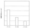
- (Case 1) A conventional heat treatment apparatus having no gas supply unit 344 was used. During the PEB process, the central exhaust portion 317 exhausted and the processing gas was discharged from the shower head 311, but the peripheral exhaust portion 323 did not exhaust.
- (Case 2) The heat treatment apparatus 40 shown in FIG. 4 and the like was used. Evacuation by the peripheral exhaust part 323 and ejection of the processing gas from the shower head 311 were performed so that the gas supply from the gas supply part 344 was continued from the start to the end of the PEB process. Further, during the PEB process, no exhaust was performed by the central exhaust section 317 at all. (Case 3) The heat treatment apparatus 40 shown in FIG. 4 and the like was used.
- Evacuation by the peripheral exhaust part 323 and ejection of the processing gas from the shower head 311 were performed so that the gas supply from the gas supply part 344 was continued from the start to the end of the PEB process.
- the central exhaust part 317 performed exhaust from the middle of the PEB process to the end of the PEB process.
- Heat treatment apparatus 200 Control unit 300 Chamber 310 Ceiling unit 311 shower head 317 Central exhaust unit 323 Peripheral exhaust unit 328 Hot plate 344 Gas supply unit K1 Processing space W Wafer
Landscapes
- Engineering & Computer Science (AREA)
- Physics & Mathematics (AREA)
- Condensed Matter Physics & Semiconductors (AREA)
- General Physics & Mathematics (AREA)
- Manufacturing & Machinery (AREA)
- Computer Hardware Design (AREA)
- Microelectronics & Electronic Packaging (AREA)
- Power Engineering (AREA)
- Exposure Of Semiconductors, Excluding Electron Or Ion Beam Exposure (AREA)
- Plasma & Fusion (AREA)
- Chemical & Material Sciences (AREA)
- Analytical Chemistry (AREA)
Abstract
Provided is a thermal treatment device that thermally treats a substrate on which a resist coating is formed and an exposure process has been performed on the resist coating. The thermal treatment device includes: a heat plate that supports and heats the substrate; a chamber that houses the heat plate. The chamber includes: a ceiling part that forms thereunder a processing space for thermal treatment and faces the substrate on the heat plate; a gas discharge unit that is provided in the ceiling part and discharges a process gas downward toward the substrate on the heat plate; a gas supply unit that supplies a gas toward the substrate on the heat plate from a position lateral to the substrate on the heat plate and below the processing space; a central evacuation unit that evacuates the processing space in the chamber from a position that is in the ceiling part and closer in top view to the center of the substrate on the heat plate; a peripheral evacuation unit that evacuates the processing space from a position that is in the ceiling part and is closer in top view to the periphery of the substrate on the heat plate than the central evacuation unit; and a control unit. The control unit performs control such that the discharge by the gas discharge unit, the supply of the gas by the gas supply unit, and the evacuation by the peripheral evacuation unit are continued during the thermal treatment and the intensity of the evacuation by the central evacuation unit increases from a point during the thermal treatment.
Description
本開示は、熱処理装置、熱処理方法及び記憶媒体に関する。
The present disclosure relates to a heat treatment apparatus, a heat treatment method, and a storage medium.
特許文献1には、放射線により基板をパターン化するための方法が開示されている。この方法は、選択されたパターンに沿って被覆基板を照射して、照射コーティングの領域及び被照射コーティングの領域を有する照射構造を形成するステップを含む。被覆基板は、金属炭素結合及び/または金属カルボキシラート結合により有機配位子を有する金属オキソ‐ヒドロキソネットワークを含むコーティングを含む。
Patent Document 1 discloses a method for patterning a substrate with radiation. The method includes irradiating a coated substrate along a selected pattern to form an irradiated structure having regions of irradiated coating and regions of irradiated coating. Coated substrates include coatings containing metal oxo-hydroxo networks with organic ligands via metal carbon bonds and/or metal carboxylate bonds.
本開示にかかる技術は、基板上のレジストの被膜から生じた昇華物による基板の汚染を抑制すると共に、熱処理の基板面内均一性を向上させる。
The technology according to the present disclosure suppresses contamination of the substrate by a sublimate generated from the resist coating on the substrate, and improves the substrate in-plane uniformity of heat treatment.
本開示の一態様は、レジストの被膜が形成され、当該被膜に露光処理が施された基板を熱処理する熱処理装置であって、前記基板を支持して加熱する熱板と、前記熱板を収容するチャンバと、を備え、前記チャンバは、下方に前記熱処理を行う処理空間を形成し、前記熱板上の前記基板に対向する天井部を有し、前記天井部に設けられ、処理用ガスを前記熱板上の前記基板に向けて上方から吐出するガス吐出部と、前記熱板上の前記基板の側方であって前記処理空間の下部から、前記熱板上の前記基板に向けて気体を供給する気体供給部と、前記天井部における、上面視で前記熱板上の前記基板の中央寄りの位置から、前記チャンバ内における前記処理空間内を排気する中央排気部と、前記天井部における、上面視で前記中央排気部よりも前記熱板上の前記基板の周縁部側から、前記処理空間内を排気する周縁排気部と、制御部と、をさらに備え、前記制御部は、前記熱処理中、前記ガス吐出部による吐出、前記気体供給部による気体の供給及び前記周縁排気部による排気が継続されると共に、前記熱処理の途中から前記中央排気部による排気が強くなるよう、制御を行う。
One aspect of the present disclosure is a heat treatment apparatus for heat-treating a substrate on which a resist film is formed and the film is subjected to exposure processing, comprising: a hot plate supporting and heating the substrate; a chamber for performing the heat treatment, the chamber forming a processing space in which the heat treatment is performed, and having a ceiling facing the substrate on the hot plate; a gas discharge part for discharging from above toward the substrate on the hot plate, and a gas from a side of the substrate on the hot plate and below the processing space toward the substrate on the hot plate. a central exhaust unit for exhausting the inside of the processing space in the chamber from a position near the center of the substrate on the hot plate in top view in the ceiling portion; a peripheral edge exhaust section that exhausts the inside of the processing space from a peripheral edge side of the substrate on the hot plate rather than the central exhaust section when viewed from above; and a controller, wherein the controller controls the heat treatment During the heat treatment, control is performed so that discharge by the gas discharge unit, gas supply by the gas supply unit, and exhaust by the peripheral exhaust unit are continued, and exhaust by the central exhaust unit is strengthened from the middle of the heat treatment.
本開示によれば、基板上のレジストの被膜から生じた昇華物による基板の汚染を抑制すると共に、熱処理の基板面内均一性を向上させることができる。
According to the present disclosure, it is possible to suppress contamination of the substrate by a sublimate generated from the resist coating on the substrate, and improve uniformity of heat treatment within the substrate surface.
半導体デバイス等の製造プロセスでは、半導体ウェハ(以下、「ウェハ」という。)上にレジストパターンを形成するため所定の処理が行われる。上記所定の処理とは、例えば、ウェハ上にレジスト液を供給しレジストの被膜を形成するレジスト塗布処理や、上記被膜を露光する露光処理、露光後に上記被膜内の化学反応が促進するよう加熱するPEB(Post Exposure Bake)処理、露光された上記被膜を現像する現像処理等である。
In the manufacturing process of semiconductor devices, etc., a predetermined process is performed to form a resist pattern on a semiconductor wafer (hereinafter referred to as "wafer"). The predetermined processing includes, for example, a resist coating process of supplying a resist solution onto a wafer to form a resist coating, an exposure process of exposing the coating, and heating to promote a chemical reaction in the coating after exposure. These include PEB (Post Exposure Bake) processing, development processing for developing the exposed film, and the like.
PEB処理は、例えば、基板の周囲の雰囲気を排気しながら行われる。この場合、排気の形態等によっては、レジストパターンの寸法が面内でばらつくことがある。また、メタル含有レジスト等の、昇華物が生じるレジストの場合、排気の形態等によっては、昇華物により、基板のベベル部分や裏面が汚染されることがある。
The PEB process is performed, for example, while evacuating the atmosphere around the substrate. In this case, the dimensions of the resist pattern may vary within the plane depending on the form of the exhaust. Further, in the case of a resist such as a metal-containing resist that generates sublimate, the sublimate may contaminate the bevel portion and the back surface of the substrate depending on the form of exhaust.
そこで、本開示にかかる技術は、基板上のレジストの被膜から生じた昇華物による基板の汚染を抑制すると共に、熱処理の基板面内均一性を向上させる。
Therefore, the technique according to the present disclosure suppresses the contamination of the substrate by the sublimate generated from the resist coating on the substrate, and improves the substrate in-plane uniformity of the heat treatment.
以下、本実施形態にかかる熱処理装置及び熱処理方法を、図面を参照して説明する。なお、本明細書及び図面において、実質的に同一の機能構成を有する要素においては、同一の符号を付することにより重複説明を省略する。
The heat treatment apparatus and heat treatment method according to this embodiment will be described below with reference to the drawings. In the present specification and drawings, elements having substantially the same functional configuration are denoted by the same reference numerals, thereby omitting redundant description.
<塗布現像システム>
図1は、本実施形態にかかる熱処理装置を含む、基板処理システムとしての塗布現像システムの内部構成の概略を示す説明図である。図2及び図3はそれぞれ、塗布現像システムの正面側と背面側の内部構成の概略を示す図である。 <Coating and developing system>
FIG. 1 is an explanatory diagram showing the outline of the internal configuration of a coating and developing system as a substrate processing system including a heat treatment apparatus according to this embodiment. 2 and 3 are diagrams showing the outline of the internal configuration on the front side and the back side of the coating and developing system, respectively.
塗布現像システム1は、レジストを用いて、基板としてのウェハWにレジストパターンを形成する。用いられレジストは、昇華物を生じるようなレジストであり、例えば金属含有レジストである。なお、金属含有レジストに含まれる金属は任意であるが、例えばスズである。
The coating and developing system 1 uses a resist to form a resist pattern on a wafer W as a substrate. The resists used are those which produce sublimates, for example metal-containing resists. The metal contained in the metal-containing resist is arbitrary, but is tin, for example.
塗布現像システム1は、図1~図3に示すように、ウェハを複数収容可能な容器であるカセットCが搬入出されるカセットステーション2と、レジスト塗布処理等の所定の処理を施す各種処理装置を複数備えた処理ステーション3と、を有する。そして、塗布現像システム1は、カセットステーション2と、処理ステーション3と、処理ステーション3に隣接する露光装置4との間でウェハWの受け渡しを行うインターフェイスステーション5とを一体に接続した構成を有している。
As shown in FIGS. 1 to 3, the coating and developing system 1 includes a cassette station 2 for loading and unloading a cassette C, which is a container capable of accommodating a plurality of wafers, and various processing devices for performing predetermined processing such as resist coating processing. and a plurality of processing stations 3 . The coating and developing system 1 has a configuration in which a cassette station 2, a processing station 3, and an interface station 5 for transferring wafers W between an exposure apparatus 4 adjacent to the processing station 3 are integrally connected. ing.
カセットステーション2は、例えばカセット搬入出部10とウェハ搬送部11に分かれている。例えばカセット搬入出部10は、塗布現像システム1のY方向負方向(図1の左方向)側の端部に設けられている。カセット搬入出部10には、カセット載置台12が設けられている。カセット載置台12上には、複数、例えば4つの載置板13が設けられている。載置板13は、水平方向のX方向(図1の上下方向)に一列に並べて設けられている。これらの載置板13には、塗布現像システム1の外部に対してカセットCを搬入出する際に、カセットCを載置することができる。
The cassette station 2 is divided into, for example, a cassette loading/unloading section 10 and a wafer transfer section 11 . For example, the cassette loading/unloading section 10 is provided at the end of the coating and developing system 1 in the negative Y direction (leftward direction in FIG. 1). A cassette mounting table 12 is provided in the cassette loading/unloading section 10 . A plurality of, for example, four mounting plates 13 are provided on the cassette mounting table 12 . The mounting plates 13 are arranged in a row in the horizontal X direction (vertical direction in FIG. 1). The cassette C can be placed on these mounting plates 13 when the cassette C is carried into and out of the coating and developing system 1 .
ウェハ搬送部11には、ウェハWを搬送する搬送装置20が設けられている。搬送装置20は、X方向に延びる搬送路21を移動自在に構成されている。搬送装置20は、上下方向及び鉛直軸周り(θ方向)にも移動自在であり、各載置板13上のカセットCと、後述する処理ステーション3の第3のブロックG3の受け渡し装置との間でウェハWを搬送できる。
A transfer device 20 for transferring the wafer W is provided in the wafer transfer unit 11 . The transport device 20 is configured to be movable along a transport path 21 extending in the X direction. The conveying device 20 is movable in the vertical direction and around the vertical axis (the direction of θ), and is between the cassette C on each mounting plate 13 and the transfer device of the third block G3 of the processing station 3, which will be described later. , the wafer W can be transported.
処理ステーション3には、各種装置を備えた複数、例えば第1~第4の4つのブロックG1、G2、G3、G4が設けられている。例えば処理ステーション3の正面側(図1のX方向負方向側)には、第1のブロックG1が設けられ、処理ステーション3の背面側(図1のX方向正方向側)には、第2のブロックG2が設けられている。また、処理ステーション3のカセットステーション2側(図1のY方向負方向側)には、第3のブロックG3が設けられ、処理ステーション3のインターフェイスステーション5側(図1のY方向正方向側)には、第4のブロックG4が設けられている。
The processing station 3 is provided with a plurality of, for example, first to fourth blocks G1, G2, G3, and G4, which are equipped with various devices. For example, a first block G1 is provided on the front side of the processing station 3 (negative X direction side in FIG. 1), and a second block G1 is provided on the back side of the processing station 3 (positive X direction side in FIG. 1). A block G2 of is provided. A third block G3 is provided on the cassette station 2 side of the processing station 3 (negative Y direction side in FIG. 1), and the interface station 5 side of the processing station 3 (positive Y direction side in FIG. 1). is provided with a fourth block G4.
第1のブロックG1には、図2に示すように複数の液処理装置、例えば現像処理装置30、下部反射防止膜形成装置31、レジスト塗布装置32、上部反射防止膜形成装置33が下からこの順に配置されている。現像処理装置30は、ウェハWに現像処理を施す。具体的には、現像処理装置30は、PEB処理が施されたウェハWの金属含有レジスト膜に現像処理を施す。下部反射防止膜形成装置31は、ウェハWの金属含有レジスト膜の下層に反射防止膜(以下、「下部反射防止膜」という。)を形成する。レジスト塗布装置32は、ウェハWに金属含有レジストを塗布して金属含有レジストの被膜すなわち金属含有レジスト膜を形成する。上部反射防止膜形成装置33は、ウェハWの金属含有レジスト膜の上層に反射防止膜(以下、「上部反射防止膜」という。)を形成する。
In the first block G1, as shown in FIG. 2, a plurality of liquid processing devices such as a developing device 30, a lower antireflection film forming device 31, a resist coating device 32, and an upper antireflection film forming device 33 are arranged from below. are arranged in order. The development processing device 30 subjects the wafer W to development processing. Specifically, the development processing device 30 develops the metal-containing resist film of the wafer W that has undergone the PEB processing. The lower antireflection film forming apparatus 31 forms an antireflection film (hereinafter referred to as “lower antireflection film”) on the wafer W under the metal-containing resist film. The resist coating device 32 coats the wafer W with a metal-containing resist to form a coating of the metal-containing resist, that is, a metal-containing resist film. The upper antireflection film forming apparatus 33 forms an antireflection film (hereinafter referred to as “upper antireflection film”) on the metal-containing resist film of the wafer W. As shown in FIG.
例えば現像処理装置30、下部反射防止膜形成装置31、レジスト塗布装置32、上部反射防止膜形成装置33は、それぞれ水平方向に3つ並べて配置されている。なお、これら現像処理装置30、下部反射防止膜形成装置31、レジスト塗布装置32、上部反射防止膜形成装置33の数や配置は、任意に選択できる。
For example, three development processing devices 30, lower antireflection film forming devices 31, resist coating devices 32, and upper antireflection film forming devices 33 are arranged horizontally. The number and arrangement of the developing device 30, the lower antireflection film forming device 31, the resist coating device 32, and the upper antireflection film forming device 33 can be arbitrarily selected.
現像処理装置30、下部反射防止膜形成装置31、レジスト塗布装置32、上部反射防止膜形成装置33では、例えばスピン塗布法でウェハW上に所定の処理液を塗布する。スピン塗布法では、例えば吐出ノズルからウェハW上に処理液を吐出すると共に、ウェハWを回転させて、処理液をウェハWの表面に拡散させる。
In the developing device 30, the lower anti-reflection film forming device 31, the resist coating device 32, and the upper anti-reflection film forming device 33, a predetermined processing liquid is applied onto the wafer W by spin coating, for example. In the spin coating method, for example, the processing liquid is discharged onto the wafer W from a discharge nozzle, and the wafer W is rotated to spread the processing liquid on the surface of the wafer W. FIG.
例えば第2のブロックG2には、図3に示すようにウェハWを熱処理する熱処理装置40が上下方向と水平方向に並べて設けられている。熱処理装置40の数や配置についても、任意に選択できる。なお、熱処理装置40では、レジスト塗布処理後のウェハWを加熱処理するプリベーキング処理(以下、「PAB処理」という。)、露光処理後のウェハWを加熱処理するPEB処理、現像処理後のウェハWを加熱処理するポストベーキング処理(以下、「POST処理」という。)等を行う。
For example, in the second block G2, as shown in FIG. 3, heat treatment apparatuses 40 for heat-treating wafers W are arranged vertically and horizontally. The number and arrangement of heat treatment apparatuses 40 can also be arbitrarily selected. Note that the heat treatment apparatus 40 performs a pre-baking process (hereinafter referred to as "PAB process") for heat-treating the wafer W after the resist coating process, a PEB process for heat-treating the wafer W after the exposure process, and a wafer after the development process. A post-baking process (hereinafter referred to as "POST process") for heat-treating W is performed.
例えば第3のブロックG3には、複数の受け渡し装置50、51、52、53、54、55、56が下から順に設けられている。また、第4のブロックG4には、複数の受け渡し装置60、61、62と、ウェハWの裏面を洗浄する裏面洗浄装置63が下から順に設けられている。
For example, in the third block G3, a plurality of transfer devices 50, 51, 52, 53, 54, 55, and 56 are provided in order from the bottom. Further, in the fourth block G4, a plurality of transfer devices 60, 61, 62 and a back surface cleaning device 63 for cleaning the back surface of the wafer W are provided in this order from the bottom.
図1に示すように第1のブロックG1~第4のブロックG4に囲まれた領域には、ウェハ搬送領域Dが形成されている。ウェハ搬送領域Dには、例えばウェハWを搬送する基板搬送装置としての搬送装置70が配置されている。
As shown in FIG. 1, a wafer transfer area D is formed in the area surrounded by the first block G1 to the fourth block G4. In the wafer transfer area D, a transfer device 70 as a substrate transfer device for transferring the wafer W, for example, is arranged.
搬送装置70は、例えばY方向、θ方向及び上下方向に移動自在な搬送アーム70aを有している。搬送装置70は、ウェハWを保持した搬送アーム70aをウェハ搬送領域D内で移動させ、周囲の第1のブロックG1、第2のブロックG2、第3のブロックG3及び第4のブロックG4内の所定の装置に、ウェハWを搬送できる。搬送装置70は、例えば図3に示すように上下に複数台配置され、例えば各ブロックG1~G4の同程度の高さの所定の装置にウェハWを搬送できる。
The transport device 70 has a transport arm 70a that is movable in, for example, the Y direction, the θ direction, and the vertical direction. The transfer device 70 moves the transfer arm 70a holding the wafer W within the wafer transfer region D, and moves the transfer arm 70a within the surrounding first block G1, second block G2, third block G3 and fourth block G4. A wafer W can be transported to a predetermined device. For example, as shown in FIG. 3, a plurality of transport devices 70 are arranged vertically, and wafers W can be transported to predetermined devices having approximately the same height in blocks G1 to G4, for example.
また、ウェハ搬送領域Dには、第3のブロックG3と第4のブロックG4との間で直線的にウェハWを搬送するシャトル搬送装置80が設けられている。
Also, in the wafer transfer area D, a shuttle transfer device 80 is provided for transferring the wafer W linearly between the third block G3 and the fourth block G4.
シャトル搬送装置80は、支持したウェハWをY方向に直線的に移動させ、同程度の高さの第3のブロックG3の受け渡し装置52と第4のブロックG4の受け渡し装置62との間でウェハWを搬送できる。
The shuttle transport device 80 linearly moves the supported wafer W in the Y direction, and transfers the wafer between the transfer device 52 of the third block G3 and the transfer device 62 of the fourth block G4, which are approximately the same height. W can be transported.
図1に示すように第3のブロックG3のX方向正方向側には、搬送装置90が設けられている。搬送装置90は、例えばθ方向及び上下方向に移動自在な搬送アーム90aを有している。搬送装置90は、ウェハWを保持した搬送アーム90aを上下に移動させ、第3のブロックG3内の各受け渡し装置に、ウェハWを搬送できる。
As shown in FIG. 1, a conveying device 90 is provided on the positive side of the X direction of the third block G3. The transport device 90 has a transport arm 90a that is movable in, for example, the θ direction and the vertical direction. The transfer device 90 can move the transfer arm 90a holding the wafer W up and down to transfer the wafer W to each transfer device in the third block G3.
インターフェイスステーション5には、搬送装置100と受け渡し装置101が設けられている。搬送装置100は、例えばθ方向及び上下方向に移動自在な搬送アーム100aを有している。搬送装置100は、搬送アーム100aにウェハWを保持して、第4のブロックG4内の各受け渡し装置、受け渡し装置101及び露光装置4との間でウェハWを搬送できる。
The interface station 5 is provided with a transport device 100 and a transfer device 101 . The transport device 100 has a transport arm 100a that is movable in, for example, the θ direction and the vertical direction. The transfer device 100 can hold the wafer W on the transfer arm 100a and transfer the wafer W between the transfer devices, the transfer device 101 and the exposure device 4 in the fourth block G4.
以上の塗布現像システム1には、図1に示すように制御部200が設けられている。制御部200は、例えばCPU等のプロセッサやメモリ等を備えたコンピュータであり、プログラム格納部(図示せず)を有している。プログラム格納部には、上述の各種処理装置や各種搬送装置等の駆動系の動作を制御して、後述のウェハ処理を制御するプログラムが格納されている。なお、上記プログラムは、コンピュータに読み取り可能な非一時的な記憶媒体Hに記録されていたものであって、当該記憶媒体Hから制御部200にインストールされたものであってもよい。記憶媒体Hは、一時的なものであっても、非一時的なものであってもよい。プログラムの一部または全ては専用ハードウェア(回路基板)で実現してもよい。
The coating and developing system 1 described above is provided with a control section 200 as shown in FIG. The control unit 200 is, for example, a computer including a processor such as a CPU, a memory, and the like, and has a program storage unit (not shown). The program storage unit stores a program for controlling the operation of drive systems such as the above-described various processing devices and various transfer devices, and for controlling wafer processing, which will be described later. The program may be recorded in a non-temporary computer-readable storage medium H and installed in the control unit 200 from the storage medium H. The storage medium H may be temporary or non-temporary. Part or all of the program may be realized by dedicated hardware (circuit board).
<塗布現像システム1を用いたウェハ処理>
次に、塗布現像システム1を用いたウェハ処理の一例について説明する。なお、以下の処理は、制御部200の制御の下、行われる。 <Wafer processing using coating and developingsystem 1>
Next, an example of wafer processing using the coating and developingsystem 1 will be described. Note that the following processing is performed under the control of the control unit 200. FIG.
次に、塗布現像システム1を用いたウェハ処理の一例について説明する。なお、以下の処理は、制御部200の制御の下、行われる。 <Wafer processing using coating and developing
Next, an example of wafer processing using the coating and developing
先ず、複数のウェハWを収納したカセットCが、塗布現像システム1のカセットステーション2に搬入され、載置板13に載置される。その後、搬送装置20によりカセットC内の各ウェハWが順次取り出され、処理ステーション3の第3のブロックG3の受け渡し装置53に搬送される。
First, a cassette C containing a plurality of wafers W is carried into the cassette station 2 of the coating and developing system 1 and placed on the placing plate 13 . After that, each wafer W in the cassette C is sequentially taken out by the transfer device 20 and transferred to the delivery device 53 of the third block G3 of the processing station 3 .
次に、ウェハWは、搬送装置70によって第2のブロックG2の熱処理装置40に搬送され温度調節処理される。その後、ウェハWは、搬送装置70によって例えば第1のブロックG1の下部反射防止膜形成装置31に搬送され、ウェハW上に下部反射防止膜が形成される。その後、ウェハWは、第2のブロックG2の熱処理装置40に搬送され、加熱処理が行われる。その後、ウェハWは、第3のブロックG3の受け渡し装置53に戻される。
Next, the wafer W is transferred by the transfer device 70 to the heat treatment device 40 of the second block G2 and subjected to temperature control processing. After that, the wafer W is transferred by the transfer device 70 to, for example, the lower antireflection film forming device 31 of the first block G1, and a lower antireflection film is formed on the wafer W. FIG. After that, the wafer W is transported to the heat treatment device 40 of the second block G2 and subjected to heat treatment. After that, the wafer W is returned to the delivery device 53 of the third block G3.
次に、ウェハWは、搬送装置70によってレジスト塗布装置32に搬送され、ウェハW上に金属含有レジスト膜が形成される。その後、ウェハWは、搬送装置70によって熱処理装置40に搬送されて、PAB処理される。その後、ウェハWは、搬送装置70によって第3のブロックG3の受け渡し装置55に搬送される。
Next, the wafer W is transferred to the resist coating device 32 by the transfer device 70, and a metal-containing resist film is formed on the wafer W. After that, the wafer W is transferred to the heat treatment apparatus 40 by the transfer apparatus 70 and subjected to the PAB process. After that, the wafer W is transferred by the transfer device 70 to the delivery device 55 of the third block G3.
次に、ウェハWは、搬送装置70によって上部反射防止膜形成装置33に搬送され、ウェハW上に上部反射防止膜が形成される。その後、ウェハWは、搬送装置70によって熱処理装置40に搬送されて、加熱され、温度調節される。
Next, the wafer W is transferred by the transfer device 70 to the upper antireflection film forming device 33, and an upper antireflection film is formed on the wafer W. After that, the wafer W is transferred to the heat treatment apparatus 40 by the transfer apparatus 70, heated, and temperature-controlled.
その後、ウェハWは、搬送装置70によって第3のブロックG3の受け渡し装置56に搬送される。
After that, the wafer W is transferred by the transfer device 70 to the delivery device 56 of the third block G3.
次に、ウェハWは、搬送装置90によって受け渡し装置52に搬送され、シャトル搬送装置80によって第4のブロックG4の受け渡し装置62に搬送される。その後、ウェハWは、搬送装置100によって裏面洗浄装置63に搬送され、裏面洗浄される。次いで、ウェハWは、インターフェイスステーション5の搬送装置100によって露光装置4に搬送され、EUV光を用いて所定のパターンで露光処理される。
Next, the wafer W is transferred to the transfer device 52 by the transfer device 90, and transferred to the transfer device 62 of the fourth block G4 by the shuttle transfer device 80. After that, the wafer W is transferred by the transfer device 100 to the back surface cleaning device 63, and the back surface thereof is cleaned. Next, the wafer W is transferred to the exposure apparatus 4 by the transfer apparatus 100 of the interface station 5, and exposed in a predetermined pattern using EUV light.
次に、ウェハWは、搬送装置100によって第4のブロックG4の受け渡し装置60に搬送される。その後、ウェハWは、熱処理装置40に搬送され、PEB処理される。
Next, the wafer W is transferred by the transfer device 100 to the delivery device 60 of the fourth block G4. After that, the wafer W is transported to the heat treatment apparatus 40 and subjected to PEB processing.
次に、ウェハWは、搬送装置70によって現像処理装置30に搬送され、現像される。現像終了後、ウェハWは、搬送装置90によって熱処理装置40に搬送され、POST処理される。
Next, the wafer W is transported to the developing treatment device 30 by the transport device 70 and developed. After completion of the development, the wafer W is transported to the heat treatment apparatus 40 by the transport apparatus 90 and subjected to POST processing.
その後、ウェハWは、搬送装置70によって第3のブロックG3の受け渡し装置50に搬送され、その後カセットステーション2の搬送装置20によって所定の載置板13のカセットCに搬送される。こうして、一連のフォトリソグラフィー工程が終了する。
After that, the wafer W is transferred by the transfer device 70 to the transfer device 50 of the third block G3, and then transferred to the cassette C on the predetermined mounting plate 13 by the transfer device 20 of the cassette station 2. Thus, a series of photolithography steps are completed.
<熱処理装置>
次に、熱処理装置40のうち、PEB処理に用いられる熱処理装置40について説明する。図4は、PEB処理に用いられる熱処理装置40の構成の概略を模式的に示す縦断面図である。図5は、後述の上チャンバ301の構成の概略を模式的に示す下面図である。 <Heat treatment equipment>
Next, among theheat treatment apparatuses 40, the heat treatment apparatus 40 used for PEB processing will be described. FIG. 4 is a vertical cross-sectional view schematically showing the outline of the configuration of a heat treatment apparatus 40 used for PEB processing. FIG. 5 is a bottom view schematically showing the outline of the configuration of the upper chamber 301, which will be described later.
次に、熱処理装置40のうち、PEB処理に用いられる熱処理装置40について説明する。図4は、PEB処理に用いられる熱処理装置40の構成の概略を模式的に示す縦断面図である。図5は、後述の上チャンバ301の構成の概略を模式的に示す下面図である。 <Heat treatment equipment>
Next, among the
図4の熱処理装置40は、チャンバ300を備える。チャンバ300は、上チャンバ301と、下チャンバ302と、整流部材303と、を備える。上チャンバ301は上側に位置し、下チャンバ302は下側に位置する。整流部材303は、上チャンバ301と下チャンバ302との間に位置し、具体的には、上チャンバ301の周縁部と下チャンバ302の周縁部との間に位置する。
The heat treatment apparatus 40 in FIG. 4 includes a chamber 300. The chamber 300 includes an upper chamber 301 , a lower chamber 302 and a straightening member 303 . The upper chamber 301 is positioned above and the lower chamber 302 is positioned below. The rectifying member 303 is positioned between the upper chamber 301 and the lower chamber 302 , specifically between the peripheral edge of the upper chamber 301 and the peripheral edge of the lower chamber 302 .
上チャンバ301は、昇降自在に構成されている。上チャンバ301を昇降させる、モータ等の駆動源を有する昇降機構(図示せず)は、制御部200により制御される。
また、上チャンバ301は、例えば、円板状に形成されている。上チャンバ301は天井部310を有する。天井部310は、下方に熱処理を行う処理空間K1を形成しており、熱板328上のウェハWに対向するように設けられる。また、天井部310には、ガス吐出部としてのシャワーヘッド311が設けられている。 Theupper chamber 301 is configured to be vertically movable. An elevating mechanism (not shown) having a driving source such as a motor for elevating the upper chamber 301 is controlled by the controller 200 .
Also, theupper chamber 301 is formed in a disc shape, for example. Upper chamber 301 has a ceiling 310 . The ceiling part 310 forms a processing space K<b>1 in which heat treatment is performed below, and is provided so as to face the wafer W on the heating plate 328 . Also, the ceiling portion 310 is provided with a shower head 311 as a gas discharge portion.
また、上チャンバ301は、例えば、円板状に形成されている。上チャンバ301は天井部310を有する。天井部310は、下方に熱処理を行う処理空間K1を形成しており、熱板328上のウェハWに対向するように設けられる。また、天井部310には、ガス吐出部としてのシャワーヘッド311が設けられている。 The
Also, the
シャワーヘッド311は、熱板328上のウェハWに向けて、処理用ガスを、上方から吐出する。処理用ガスは、例えば、水分を含有したガスすなわち水分含有ガスである。
シャワーヘッド311は、複数の吐出孔312と、ガス分配空間313と、を有する。 Theshower head 311 discharges the processing gas from above toward the wafer W on the hot plate 328 . The processing gas is, for example, a gas containing water, ie, a water-containing gas.
Showerhead 311 has a plurality of outlet holes 312 and gas distribution space 313 .
シャワーヘッド311は、複数の吐出孔312と、ガス分配空間313と、を有する。 The
吐出孔312はそれぞれ、シャワーヘッド311の下面に形成されている。吐出孔312は、例えば、図5に示すように、シャワーヘッド311の下面において、後述する排気孔以外の部分に略均一に配置されている。複数の吐出孔312は、熱板328上のウェハWの周縁部の上方に位置する第1吐出孔と、熱板328上のウェハWの中央部の上方に位置する第2吐出孔と、を含む。
The discharge holes 312 are formed on the lower surface of the shower head 311 respectively. For example, as shown in FIG. 5, the discharge holes 312 are arranged substantially uniformly on the lower surface of the shower head 311 except for exhaust holes, which will be described later. The plurality of discharge holes 312 includes a first discharge hole positioned above the peripheral portion of the wafer W on the hot plate 328 and a second discharge hole positioned above the central portion of the wafer W on the hot plate 328 . include.
ガス分配空間313は、当該ガス分配空間313に供給された処理用ガスを分配して各吐出孔312に供給する。図4に示すように、シャワーヘッド311には、ガス供給管314を介して、処理用ガスを貯留する処理用ガス源315が接続されている。ガス供給管314には、処理用ガスの流通を制御するバルブや流量調節弁等を含む供給機器群316が設けられている。
The gas distribution space 313 distributes the processing gas supplied to the gas distribution space 313 and supplies it to each discharge hole 312 . As shown in FIG. 4 , a processing gas source 315 that stores processing gas is connected to the shower head 311 via a gas supply pipe 314 . The gas supply pipe 314 is provided with a supply device group 316 including a valve for controlling the flow of the processing gas, a flow control valve, and the like.
さらに、上チャンバ301の天井部310には中央排気部317が設けられている。中央排気部317は、天井部310における、熱板328上のウェハWの上面視中央寄りの位置から(図の例では上記中央の位置から)、チャンバ300内における熱板328の上方の処理空間K1内を排気する。中央排気部317は排気孔318を有する。排気孔318は、図5に示すように、シャワーヘッド311の下面における、熱板328上のウェハWの上面視中央寄りの位置(図の例では上記中央の位置)に設けられており、下方に開口している。中央排気部317は、この排気孔318を介して、処理空間K1内を排気する。
また、図示はしていないが、排気口318は、ウェハWの中心の直上にあたる位置を囲むように、複数設けられても良い。この場合、後述の中央排気部317による排気の作用を損なわないように、例えば上面視でウェハWの中心からウェハ半径の3分の1以内の領域における位置に、上記の複数の排気口318は設けられる。 Furthermore, acentral exhaust section 317 is provided in the ceiling section 310 of the upper chamber 301 . The central exhaust part 317 is located in the ceiling part 310 from a position closer to the center of the wafer W on the hot plate 328 in a top view (from the above-mentioned central position in the example of the figure), and the processing space above the hot plate 328 in the chamber 300 . The inside of K1 is exhausted. Central vent 317 has vent holes 318 . As shown in FIG. 5, the exhaust hole 318 is provided on the lower surface of the shower head 311 at a position closer to the center of the wafer W on the hot plate 328 when viewed from above (in the example shown, the center position). is open to The central exhaust section 317 exhausts the inside of the processing space K<b>1 through this exhaust hole 318 .
Further, although not shown, a plurality ofexhaust ports 318 may be provided so as to surround a position directly above the center of the wafer W. In this case, the plurality of exhaust ports 318 are positioned within a region within one-third of the wafer radius from the center of the wafer W when viewed from above, for example, so as not to impair the exhaust effect of the central exhaust portion 317, which will be described later. be provided.
また、図示はしていないが、排気口318は、ウェハWの中心の直上にあたる位置を囲むように、複数設けられても良い。この場合、後述の中央排気部317による排気の作用を損なわないように、例えば上面視でウェハWの中心からウェハ半径の3分の1以内の領域における位置に、上記の複数の排気口318は設けられる。 Furthermore, a
Further, although not shown, a plurality of
図4に示すように、中央排気部317は、排気孔318から上方向に延伸するように形成された中央排気路319を有する。中央排気路319には、排気管320を介して、真空ポンプ等の排気装置321が接続されている。排気管320には、排気量を調整するバルブ等を有する排気機器群322が設けられている。
As shown in FIG. 4 , the central exhaust section 317 has a central exhaust path 319 extending upward from the exhaust hole 318 . An exhaust device 321 such as a vacuum pump is connected to the central exhaust passage 319 via an exhaust pipe 320 . The exhaust pipe 320 is provided with an exhaust equipment group 322 having a valve for adjusting the exhaust amount.
また、上チャンバ301の天井部310には周縁排気部323が設けられている。周縁排気部323は、天井部310における、上面視で中央排気部317よりも熱板328上のウェハWの周縁部側から、処理空間K1内を排気する。周縁排気部323は、排気口324を有する。排気口324は、図5に示すように、シャワーヘッド311の外周を囲むように、天井部310の下面から、下方に開口している。排気口324は、複数の排気孔をシャワーヘッド311の外周に沿って並べたものであってもよい。周縁排気部323は、この排気口324を介して、処理空間K1内を排気する。
In addition, a peripheral exhaust portion 323 is provided in the ceiling portion 310 of the upper chamber 301 . The peripheral exhaust portion 323 exhausts the inside of the processing space K1 from the peripheral portion side of the wafer W on the hot plate 328 rather than the central exhaust portion 317 in the top view of the ceiling portion 310 . The peripheral exhaust portion 323 has an exhaust port 324 . As shown in FIG. 5 , the exhaust port 324 opens downward from the lower surface of the ceiling portion 310 so as to surround the outer circumference of the shower head 311 . The exhaust port 324 may be formed by arranging a plurality of exhaust holes along the outer circumference of the shower head 311 . The peripheral exhaust part 323 exhausts the inside of the processing space K<b>1 through the exhaust port 324 .
排気口324は、例えば、当該排気口324の周端が上面視で、熱板328上のウェハWの周端と重なる位置と、その内側10mmの位置との間に設けられる。
The exhaust port 324 is provided, for example, between a position where the peripheral edge of the exhaust port 324 overlaps the peripheral edge of the wafer W on the hot plate 328 and a position 10 mm inside thereof when viewed from above.
図4の周縁排気部323は、排気口324から延びる周縁排気路を有する。周縁排気路には、排気管325を介して、真空ポンプ等の排気装置326が接続されている。排気管325には、排気量を調整するバルブ等を有する排気機器群327が設けられている。
The peripheral exhaust portion 323 of FIG. 4 has a peripheral exhaust path extending from the exhaust port 324 . An exhaust device 326 such as a vacuum pump is connected to the peripheral exhaust path via an exhaust pipe 325 . The exhaust pipe 325 is provided with an exhaust device group 327 having a valve for adjusting the exhaust amount.
さらに、上チャンバ301は、当該上チャンバ301を加熱可能に構成されている。例えば、上チャンバ301には、上チャンバ301を加熱するヒータ(図示せず)が内蔵されている。このヒータが制御部200により制御され、上チャンバ301(具体的には例えばシャワーヘッド311)が所定の温度に調整される。
Furthermore, the upper chamber 301 is configured to be able to heat the upper chamber 301 . For example, the upper chamber 301 incorporates a heater (not shown) for heating the upper chamber 301 . This heater is controlled by the controller 200, and the upper chamber 301 (specifically, the shower head 311, for example) is adjusted to a predetermined temperature.
下チャンバ302は、ウェハWを支持して加熱する熱板328の周囲を囲むように設けられる。
The lower chamber 302 is provided so as to surround a hot plate 328 that supports and heats the wafer W.
熱板328は、厚みのある円盤形状を有する。また、熱板328には、例えばヒータ329が内蔵されている。そして、熱板328の温度は例えば制御部200により制御され、熱板328上に載置されたウェハWが所定の温度に加熱される。
The hot plate 328 has a thick disc shape. Further, the hot plate 328 incorporates, for example, a heater 329 . The temperature of the hot plate 328 is controlled by, for example, the controller 200, and the wafer W placed on the hot plate 328 is heated to a predetermined temperature.
さらに、熱板328は、当該熱板328にウェハWを吸着するための吸着孔330を例えば複数有している。各吸着孔330は、熱板328を厚さ方向に貫通するように形成されている。
また、各吸着孔330は、中継部材331の中継孔332に接続されている。各中継孔332は、吸着のための排気を行う排気ライン333に接続されている。 Furthermore, thehot plate 328 has, for example, a plurality of suction holes 330 for sucking the wafer W onto the hot plate 328 . Each suction hole 330 is formed so as to pass through the hot plate 328 in the thickness direction.
Also, eachsuction hole 330 is connected to a relay hole 332 of a relay member 331 . Each relay hole 332 is connected to an exhaust line 333 for performing exhaust for adsorption.
また、各吸着孔330は、中継部材331の中継孔332に接続されている。各中継孔332は、吸着のための排気を行う排気ライン333に接続されている。 Furthermore, the
Also, each
吸着孔330と中継孔332との接続は、金属製の金属部材334及び樹脂製のパッド335を介して行われる。具体的には、吸着孔330と中継孔332との接続は、金属部材334内の流路と樹脂製のパッド335内の流路を介して行われる。
The connection between the suction holes 330 and the relay holes 332 is made through metal members 334 made of metal and pads 335 made of resin. Specifically, the connection between the suction hole 330 and the relay hole 332 is made through a channel in the metal member 334 and a channel in the resin pad 335 .
金属部材334は、吸着孔330側に位置し、樹脂製のパッド335は、中継孔332側に位置する。金属部材334は、一端が、熱板328(具体的には吸着孔330)に直接接続され、他端が、対応する樹脂製のパッド335の一端に直接接続されている。言い換えると、各樹脂製のパッド335は、金属部材334を介して、対応する吸着孔330に連通し且つ熱板328に接続されている。また、樹脂製のパッド335の他端は、中継部材331(具体的には中継孔332)に直接接続されている。
The metal member 334 is positioned on the suction hole 330 side, and the resin pad 335 is positioned on the relay hole 332 side. One end of the metal member 334 is directly connected to the hot plate 328 (specifically, the suction hole 330 ), and the other end is directly connected to one end of the corresponding resin pad 335 . In other words, each resin pad 335 communicates with the corresponding suction hole 330 and is connected to the heat plate 328 via the metal member 334 . The other end of the resin pad 335 is directly connected to the relay member 331 (specifically, the relay hole 332).
金属部材334は、樹脂製のパッド335側に大径部336を有する。大径部336の内部は、前記金属部材334の熱板328に接続されている部分よりも断面積が大きい流路空間336aを有し、熱処理で発生する昇華物による詰まりのリスクが低減されている。また、この断面積が大きい流路空間336aによって、ウェハWの吸着時に処理空間K1から吸引する気体の熱が緩和されて吸着のための排気ライン333に向かって流れる。つまり、樹脂製パッド335や排気ライン333に至るまでの排気流路を構成する機器の高温による劣化リスクを抑制し得る。
The metal member 334 has a large diameter portion 336 on the resin pad 335 side. The interior of the large-diameter portion 336 has a channel space 336a having a larger cross-sectional area than the portion of the metal member 334 connected to the hot plate 328, thereby reducing the risk of clogging due to sublimation generated during heat treatment. there is Further, the passage space 336a having a large cross-sectional area reduces the heat of the gas sucked from the processing space K1 when the wafer W is sucked, and the gas flows toward the exhaust line 333 for sucking. In other words, it is possible to suppress the risk of deterioration due to high temperature of the equipment that constitutes the exhaust passage up to the resin pad 335 and the exhaust line 333 .
また、下チャンバ302内には、熱板328の下方に、ウェハWを下方から支持し昇降させる昇降ピン(図示せず)が例えば3本設けられている。昇降ピンは、モータ等の駆動源を有する昇降機構(図示せず)により昇降される。この昇降機構は制御部200により制御される。なお、熱板328の中央部には、上記昇降ピンが通過する貫通孔(図示せず)が形成されている。昇降ピンは、貫通孔を通過し、熱板の上面から突出可能である。
Further, in the lower chamber 302, for example, three elevating pins (not shown) are provided below the hot plate 328 to support and elevate the wafer W from below. The lift pins are lifted and lowered by a lift mechanism (not shown) having a drive source such as a motor. This lifting mechanism is controlled by the controller 200 . A through hole (not shown) through which the elevating pin passes is formed in the central portion of the hot plate 328 . The lifting pins can pass through the through holes and protrude from the upper surface of the hot plate.
さらに、下チャンバ302は、サポートリング337と底チャンバ338とを有する。
Furthermore, the lower chamber 302 has a support ring 337 and a bottom chamber 338.
サポートリング337は、円筒形状を有している。サポートリング337の材料には、例えばステンレス等の金属が用いられる。サポートリング337は、熱板328の外側面を覆っている。サポートリング337は、底チャンバ338の上に固定される。
The support ring 337 has a cylindrical shape. Metal such as stainless steel is used as the material of the support ring 337 . A support ring 337 covers the outer surface of the hot plate 328 . A support ring 337 is secured over the bottom chamber 338 .
底チャンバ338は、有底の円筒形状を有している。
前述の熱板328は、例えば、底チャンバ338の底壁に支持される。具体的には、熱板328は、支持部339を介して、底チャンバ338の底壁に支持される。支持部339は、例えば、上端が熱板328に接続される支持柱340と、支持柱340を支持する環状部材341と、底チャンバ338の底壁に環状部材341を支持する脚部材342と、を有する。 Thebottom chamber 338 has a cylindrical shape with a bottom.
The aforementionedhot plate 328 is supported, for example, on the bottom wall of the bottom chamber 338 . Specifically, the hot plate 328 is supported by the bottom wall of the bottom chamber 338 via the supports 339 . The support part 339 includes, for example, a support column 340 whose upper end is connected to the hot plate 328, an annular member 341 that supports the support column 340, leg members 342 that support the annular member 341 on the bottom wall of the bottom chamber 338, have
前述の熱板328は、例えば、底チャンバ338の底壁に支持される。具体的には、熱板328は、支持部339を介して、底チャンバ338の底壁に支持される。支持部339は、例えば、上端が熱板328に接続される支持柱340と、支持柱340を支持する環状部材341と、底チャンバ338の底壁に環状部材341を支持する脚部材342と、を有する。 The
The aforementioned
環状部材341は金属で形成されており、熱板328の裏面の大部分に対して支持柱340の高さの分、間隙をもって設けられている。樹脂製のパッド335を、そのように設けられている環状部材341の下方に位置せしめることで、熱板328からの熱を環状部材341が効果的に遮断し、樹脂製パッド335が高温に晒されにくく(熱劣化しにくく)している。
The annular member 341 is made of metal, and is provided with a gap corresponding to the height of the support column 340 with respect to most of the back surface of the hot plate 328 . By positioning the resin pad 335 below the annular member 341 provided in such a manner, the annular member 341 effectively blocks the heat from the hot plate 328, and the resin pad 335 is not exposed to high temperatures. It is hard to be damaged (hard to be thermally deteriorated).
さらに、下チャンバ302は、取り込み口343を有する。取り込み口343は、チャンバ300の外部から当該チャンバ300内に気体を取り込む。取り込み口343は、例えば、底チャンバ338の円筒状の側壁に形成されている。
なお、底チャンバ338の側壁の内周面と、サポートリング337の内周面とは、例えば同径である。 Additionally, thelower chamber 302 has an inlet 343 . The intake port 343 takes gas into the chamber 300 from the outside of the chamber 300 . Inlet 343 is formed, for example, in a cylindrical side wall of bottom chamber 338 .
The inner peripheral surface of the side wall of thebottom chamber 338 and the inner peripheral surface of the support ring 337 have, for example, the same diameter.
なお、底チャンバ338の側壁の内周面と、サポートリング337の内周面とは、例えば同径である。 Additionally, the
The inner peripheral surface of the side wall of the
また、チャンバ300は気体供給部344を有する。気体供給部344は、熱板328上のウェハWの表面(すなわち上面)よりも下方から、熱板328上のウェハWに向けて気体を供給する。
The chamber 300 also has a gas supply section 344 . The gas supply unit 344 supplies gas toward the wafer W on the hot plate 328 from below the surface (that is, the upper surface) of the wafer W on the hot plate 328 .
気体供給部344は、熱板328の側面を囲うように設けられた気体流路345と、整流部材303と、を含む。
The gas supply part 344 includes a gas flow path 345 provided to surround the side surface of the hot plate 328 and the straightening member 303 .
気体流路345は、例えば、熱板328の外側面とサポートリング337の内周面と間の空間で構成される。したがって、気体流路345は、例えば、平面視円環状に形成される。なお、熱板328の外側面を、支持部材を介して、下チャンバ302の側壁の内周面で支持し、上下方向に貫通する貫通孔を上記支持部材に環状に複数設け、複数の上記貫通孔を気体流路345としてもよい。
The gas flow path 345 is configured by, for example, the space between the outer surface of the hot plate 328 and the inner peripheral surface of the support ring 337 . Therefore, the gas flow path 345 is formed, for example, in an annular shape in plan view. The outer surface of the hot plate 328 is supported by the inner peripheral surface of the side wall of the lower chamber 302 via a support member, and a plurality of through holes penetrating in the vertical direction are annularly provided in the support member. A hole may be used as the gas flow path 345 .
整流部材303は、気体流路345に沿って上昇した気体を、熱板328上のウェハWに向かわせる部材である。
The straightening member 303 is a member that directs the gas rising along the gas flow path 345 toward the wafer W on the hot plate 328 .
整流部材303は、例えば平面視円環状に形成されている。
整流部材303の内周側下面は、気体流路345に沿って上昇した気体を、熱板328の中心に向かわせるガイド面となる。整流部材303の下面における内周側端は、処理空間K1の高さ、つまりウェハWが載置される熱板328の表面から、吐出孔312が形成され熱板328上のウェハWに対向するシャワーヘッド311の下面までの高さ、の2分の1以下の高さに位置する。例えば、整流部材303の下面における内周側端は、熱板328上のウェハWの表面より下方に位置する。
整流部材303の内周側部は、上面視で熱板328の周縁部と重なり、且つ、上面視で熱板328上のウェハWとは重ならない。気体流路345に沿って上昇した気体は、整流部材303の内周側下面と熱板328の周縁部の上面との間の隙間Gを通り、処理空間K1内の熱板328上のウェハWの側方から当該ウェハWに向かう。熱板328の表面から上方の空間を処理空間K1とすると、処理空間K1内に気体を流入させる隙間Gは、処理空間K1の下部に設けられている。 The straighteningmember 303 is formed, for example, in an annular shape in plan view.
The lower inner peripheral surface of the rectifyingmember 303 serves as a guide surface that guides the gas rising along the gas flow path 345 toward the center of the hot plate 328 . The inner peripheral side end of the lower surface of the rectifying member 303 faces the wafer W on the hot plate 328 from the height of the processing space K1, that is, the surface of the hot plate 328 on which the wafer W is placed. The height to the lower surface of the shower head 311 is located at a height of 1/2 or less. For example, the inner edge of the lower surface of the rectifying member 303 is located below the surface of the wafer W on the hot plate 328 .
The inner peripheral side portion of the rectifyingmember 303 overlaps the peripheral edge portion of the hot plate 328 when viewed from the top, and does not overlap the wafer W on the hot plate 328 when viewed from the top. The gas rising along the gas flow path 345 passes through the gap G between the inner peripheral side lower surface of the straightening member 303 and the peripheral upper surface of the hot plate 328, and reaches the wafer W on the hot plate 328 in the processing space K1. toward the wafer W from the side of the . Assuming that the space above the surface of the hot plate 328 is a processing space K1, a gap G for allowing gas to flow into the processing space K1 is provided below the processing space K1.
整流部材303の内周側下面は、気体流路345に沿って上昇した気体を、熱板328の中心に向かわせるガイド面となる。整流部材303の下面における内周側端は、処理空間K1の高さ、つまりウェハWが載置される熱板328の表面から、吐出孔312が形成され熱板328上のウェハWに対向するシャワーヘッド311の下面までの高さ、の2分の1以下の高さに位置する。例えば、整流部材303の下面における内周側端は、熱板328上のウェハWの表面より下方に位置する。
整流部材303の内周側部は、上面視で熱板328の周縁部と重なり、且つ、上面視で熱板328上のウェハWとは重ならない。気体流路345に沿って上昇した気体は、整流部材303の内周側下面と熱板328の周縁部の上面との間の隙間Gを通り、処理空間K1内の熱板328上のウェハWの側方から当該ウェハWに向かう。熱板328の表面から上方の空間を処理空間K1とすると、処理空間K1内に気体を流入させる隙間Gは、処理空間K1の下部に設けられている。 The straightening
The lower inner peripheral surface of the rectifying
The inner peripheral side portion of the rectifying
上記隙間Gは、気体流路345の一端に接続されている。また、気体流路345の他端は、チャンバ300内における熱板328の下方のバッファ空間K2に接続されている。熱板328の下方のバッファ空間K2は、熱板328の上方の処理空間より、体積が大きい。
The gap G is connected to one end of the gas flow path 345 . The other end of the gas flow path 345 is connected to the buffer space K2 below the hot plate 328 inside the chamber 300 . The buffer space K2 below the hot plate 328 is larger in volume than the processing space above the hot plate 328 .
整流部材303の内周面は、上チャンバ301の天井部310から下方に直線的に延びている。
The inner peripheral surface of the rectifying member 303 linearly extends downward from the ceiling portion 310 of the upper chamber 301 .
一実施形態において、整流部材303は中実体である。整流部材303の材料には、例えば、ステンレス等の金属材料が用いられる。
また、整流部材303の上面全体は、上チャンバ301の下面に接触する。
より具体的には、整流部材303は、その上面全体が、上チャンバ301の下面に接触する形態で上チャンバ301に固定され、上チャンバ301と共に昇降する。 In one embodiment, straighteningmember 303 is a solid body. A metal material such as stainless steel is used as the material of the rectifying member 303, for example.
Also, the entire upper surface of the straighteningmember 303 contacts the lower surface of the upper chamber 301 .
More specifically, the rectifyingmember 303 is fixed to the upper chamber 301 in such a manner that the entire upper surface thereof contacts the lower surface of the upper chamber 301 and moves up and down together with the upper chamber 301 .
また、整流部材303の上面全体は、上チャンバ301の下面に接触する。
より具体的には、整流部材303は、その上面全体が、上チャンバ301の下面に接触する形態で上チャンバ301に固定され、上チャンバ301と共に昇降する。 In one embodiment, straightening
Also, the entire upper surface of the straightening
More specifically, the rectifying
整流部材303が、上チャンバ301と共に下降し、下チャンバ302(具体的にはサポートリング337)に当接することで、チャンバ300が閉じられる。金属製の整流部材303と金属製のサポートリング337との接触により発塵することを抑制するため、以下のようにしてもよい。すなわち、サポートリング337における整流部材303と対向する面に、樹脂製の突起を設け、整流部材303が下降したときに、上記樹脂製の突起に接触するようにしてもよい。また、整流部材303におけるサポートリング337と対向する面に、樹脂製の突起を設け、整流部材303が下降したときに、上記樹脂製の突起とサポートリング337とが接触するようにしてもよい。これらの場合、樹脂製の突起の高さは、極力小さいことが好ましい。整流部材303の下面とサポートリング337の上面との間の隙間を小さくし、この隙間に昇華物等が入り込むのを抑制するためである。樹脂製の突起の高さは、少なくとも、整流部材303の下面とサポートリング337の上面との間の隙間が、整流部材303から熱板328上のウェハWまでの最短距離より小さくなる高さである。
The rectifying member 303 descends together with the upper chamber 301 and comes into contact with the lower chamber 302 (specifically, the support ring 337), thereby closing the chamber 300. In order to suppress generation of dust due to contact between the rectifying member 303 made of metal and the support ring 337 made of metal, the following measures may be taken. That is, a resin projection may be provided on the surface of the support ring 337 facing the rectifying member 303 so that the rectifying member 303 contacts the resin projection when the rectifying member 303 descends. A resin projection may be provided on the surface of the rectifying member 303 facing the support ring 337 so that the resin projection and the support ring 337 come into contact with each other when the rectifying member 303 descends. In these cases, the height of the resin projection is preferably as small as possible. This is to reduce the gap between the lower surface of the rectifying member 303 and the upper surface of the support ring 337, thereby suppressing entry of sublimate or the like into this gap. The height of the resin projection is such that at least the gap between the lower surface of the straightening member 303 and the upper surface of the support ring 337 is smaller than the shortest distance from the straightening member 303 to the wafer W on the hot plate 328 . be.
なお、熱処理装置40は、ウェハWを冷却する機能を有する冷却板(図示せず)を更に備えていてもよい。冷却板は、例えば、チャンバ300外の冷却位置と、その少なくとも一部がチャンバ300内に配置され当該冷却板と熱板328との間でウェハWが受け渡される受け渡し位置との間を、往復移動する。あるいは、冷却板が、水平方向に熱板328と並ぶ位置に固定され、熱処理装置40が、冷却板と熱板328との間でウェハWを搬送する搬送アームを有してもよい。
Note that the heat treatment apparatus 40 may further include a cooling plate (not shown) having a function of cooling the wafer W. The cooling plate reciprocates, for example, between a cooling position outside the chamber 300 and a transfer position at least part of which is disposed within the chamber 300 and the wafer W is transferred between the cooling plate and the hot plate 328. Moving. Alternatively, the cooling plate may be fixed at a position horizontally aligned with the hot plate 328 , and the heat treatment apparatus 40 may have a transfer arm for transferring the wafer W between the cooling plate and the hot plate 328 .
<熱処理装置40を用いたウェハ処理>
次に、熱処理装置40を用いて行われるウェハ処理の一例について、図6~図8を用いて説明する。図6~図8は、熱処理装置40を用いて行われるウェハ処理中の、熱処理装置40の状態を示す図である。なお、以下のウェハ処理は、制御部200の制御の下、行われる。 <Wafer Processing UsingHeat Treatment Apparatus 40>
Next, an example of wafer processing performed using theheat treatment apparatus 40 will be described with reference to FIGS. 6 to 8. FIG. 6 to 8 are diagrams showing the state of the heat treatment apparatus 40 during wafer processing performed using the heat treatment apparatus 40. FIG. The wafer processing described below is performed under the control of the controller 200 .
次に、熱処理装置40を用いて行われるウェハ処理の一例について、図6~図8を用いて説明する。図6~図8は、熱処理装置40を用いて行われるウェハ処理中の、熱処理装置40の状態を示す図である。なお、以下のウェハ処理は、制御部200の制御の下、行われる。 <Wafer Processing Using
Next, an example of wafer processing performed using the
(ステップS1:チャンバ内の状態調整)
まず、例えば、熱板328へのウェハWの載置に先立って、チャンバ300内の状態が調整される。
具体的には、熱板328が所定の温度に調整される。
また、処理空間K1内の湿度が調整される。処理空間K1内の湿度の調整は、図6(a)に示すように、中央排気部317による排気、周縁排気部323による排気、及び、シャワーヘッド311からの処理用ガスの吐出により行われる。 (Step S1: condition adjustment in the chamber)
First, for example, prior to placing the wafer W on thehot plate 328, the condition inside the chamber 300 is adjusted.
Specifically, thehot plate 328 is adjusted to a predetermined temperature.
Also, the humidity in the processing space K1 is adjusted. The adjustment of the humidity in the processing space K1 is performed by exhausting air from thecentral exhaust unit 317, exhausting from the peripheral exhaust unit 323, and discharging the processing gas from the shower head 311, as shown in FIG. 6A.
まず、例えば、熱板328へのウェハWの載置に先立って、チャンバ300内の状態が調整される。
具体的には、熱板328が所定の温度に調整される。
また、処理空間K1内の湿度が調整される。処理空間K1内の湿度の調整は、図6(a)に示すように、中央排気部317による排気、周縁排気部323による排気、及び、シャワーヘッド311からの処理用ガスの吐出により行われる。 (Step S1: condition adjustment in the chamber)
First, for example, prior to placing the wafer W on the
Specifically, the
Also, the humidity in the processing space K1 is adjusted. The adjustment of the humidity in the processing space K1 is performed by exhausting air from the
(ステップS2:ウェハ載置)
次に、金属含有レジストの被膜が形成されたウェハWが、熱板328に載置される。
具体的には、図6(b)に示すように、周縁排気部323による排気、及び、シャワーヘッド311からの処理用ガスの吐出を継続したまま、中央排気部317による排気のみが停止され、また、上チャンバ301が上昇される。その後、上記ウェハWが、搬送装置70によって、熱板328の上方に搬送される。次いで、昇降ピンの昇降等が行われ、搬送装置70から昇降ピンへのウェハWの受け渡し、昇降ピンから熱板328へのウェハWの受け渡しが行われ、図7(a)に示すように、ウェハWが熱板328に載置される。その後、吸着孔330を介したウェハWの熱板328への吸着が行われる。 (Step S2: Place wafer)
Next, the wafer W coated with the metal-containing resist is placed on thehot plate 328 .
Specifically, as shown in FIG. 6B, only the exhaust by thecentral exhaust unit 317 is stopped while the exhaust by the peripheral exhaust unit 323 and the discharge of the processing gas from the shower head 311 are continued. Also, the upper chamber 301 is raised. After that, the wafer W is transferred above the hot plate 328 by the transfer device 70 . Next, the lift pins are moved up and down, and the wafer W is transferred from the transfer device 70 to the lift pins and transferred from the lift pins to the hot plate 328. As shown in FIG. A wafer W is placed on the hot plate 328 . Thereafter, the wafer W is sucked onto the hot plate 328 through the suction holes 330 .
次に、金属含有レジストの被膜が形成されたウェハWが、熱板328に載置される。
具体的には、図6(b)に示すように、周縁排気部323による排気、及び、シャワーヘッド311からの処理用ガスの吐出を継続したまま、中央排気部317による排気のみが停止され、また、上チャンバ301が上昇される。その後、上記ウェハWが、搬送装置70によって、熱板328の上方に搬送される。次いで、昇降ピンの昇降等が行われ、搬送装置70から昇降ピンへのウェハWの受け渡し、昇降ピンから熱板328へのウェハWの受け渡しが行われ、図7(a)に示すように、ウェハWが熱板328に載置される。その後、吸着孔330を介したウェハWの熱板328への吸着が行われる。 (Step S2: Place wafer)
Next, the wafer W coated with the metal-containing resist is placed on the
Specifically, as shown in FIG. 6B, only the exhaust by the
(ステップS3:PEB処理)
続いて、熱板328上のウェハWがPEB処理される。 (Step S3: PEB processing)
Subsequently, the wafer W on thehot plate 328 is PEB-processed.
続いて、熱板328上のウェハWがPEB処理される。 (Step S3: PEB processing)
Subsequently, the wafer W on the
(ステップS3a:PEB処理の開始)
具体的には、図7(b)に示すように、上チャンバ301が下降され、整流部材303が下チャンバ302のサポートリング337に当接し、チャンバ300が閉状態とされる。これにより、熱板328上のウェハWに対するPEB処理が開始される。 (Step S3a: Start of PEB processing)
Specifically, as shown in FIG. 7B, theupper chamber 301 is lowered, the rectifying member 303 contacts the support ring 337 of the lower chamber 302, and the chamber 300 is closed. Thereby, the PEB process for the wafer W on the hot plate 328 is started.
具体的には、図7(b)に示すように、上チャンバ301が下降され、整流部材303が下チャンバ302のサポートリング337に当接し、チャンバ300が閉状態とされる。これにより、熱板328上のウェハWに対するPEB処理が開始される。 (Step S3a: Start of PEB processing)
Specifically, as shown in FIG. 7B, the
PEB処理の開始から第1所定時間が経過するまでは、中央排気部317による排気が行われずに、シャワーヘッド311からのガスの吐出及び周縁排気部323による排気が行われる。また、シャワーヘッド311からの処理用ガスの吐出及び周縁排気部323による排気は、気体供給部344による気体供給がなされるよう、行われる。例えば、シャワーヘッド311から処理空間K1への吐出流量L1より、周縁排気部323による処理空間K1からの排気流量L2が大きくなるよう、制御が行われる。これにより、流量(L2-L1)に対応する気体が、取り込み口343を介して、チャンバ300外部からチャンバ300内へ取り込まれる。そして、流量(L2-L1)に対応する気体が、気体供給部344から熱板328上のウェハWに向けて供給される。気体供給部344から熱板328上のウェハWに向けて供給される気体の流量は、周方向に亘って略均等である。取り込み口343は、熱板328より下方の位置における、処理空間K1内に流入させる気体の導入部と言える。
Until the first predetermined time elapses from the start of the PEB process, gas is discharged from the shower head 311 and exhausted by the peripheral exhaust section 323 without being exhausted by the central exhaust section 317 . In addition, the discharge of the processing gas from the shower head 311 and the exhaust by the peripheral exhaust part 323 are performed so that the gas is supplied by the gas supply part 344 . For example, control is performed such that the discharge flow rate L2 from the processing space K1 by the peripheral exhaust portion 323 is greater than the discharge flow rate L1 from the shower head 311 to the processing space K1. As a result, the gas corresponding to the flow rate (L2−L1) is taken into the chamber 300 from the outside of the chamber 300 through the intake port 343 . Then, the gas corresponding to the flow rate (L2-L1) is supplied from the gas supply unit 344 toward the wafer W on the hot plate 328. FIG. The flow rate of the gas supplied from the gas supply part 344 toward the wafer W on the hot plate 328 is substantially uniform over the circumferential direction. The intake port 343 can be said to be an introduction portion for the gas to be introduced into the processing space K<b>1 at a position below the hot plate 328 .
周縁排気部323による排気のみを行う場合、ウェハWの表面近傍では、ウェハWの表面に沿って、ウェハWの周縁部へ径方向に移動する処理用ガスの流れが形成される。
それに対し、中央排気部317による排気を伴う場合、処理用ガスはウェハWの表面に沿って流れず、ウェハW上の周縁から中央に向かうにつれて上昇するように流れる。そのため、処理用ガスの中央排気部317に向かう気流の境界層とウェハWの表面との間隔がウェハWの面内で異なってくる。これは、ウェハW上の被膜からの揮発量のむらの要因となる。そして、この揮発量のむらは、PEB処理の初期の方における、固化が進んでおらず揮発量が多い時には、ウェハW上の膜厚の面内均一性に悪影響を与える。 When only theperipheral exhaust part 323 performs exhaust, a flow of the processing gas is formed in the vicinity of the surface of the wafer W, moving radially toward the peripheral edge of the wafer W along the surface of the wafer W. FIG.
On the other hand, when the gas is exhausted by thecentral exhaust part 317, the processing gas does not flow along the surface of the wafer W, but flows upward from the periphery of the wafer W toward the center. Therefore, the distance between the boundary layer of the airflow toward the central exhaust part 317 of the processing gas and the surface of the wafer W varies within the surface of the wafer W. FIG. This causes unevenness in the volatilization amount from the film on the wafer W. FIG. This unevenness in the volatilization amount adversely affects the in-plane uniformity of the film thickness on the wafer W when the solidification has not progressed and the volatilization amount is large in the early stages of the PEB process.
それに対し、中央排気部317による排気を伴う場合、処理用ガスはウェハWの表面に沿って流れず、ウェハW上の周縁から中央に向かうにつれて上昇するように流れる。そのため、処理用ガスの中央排気部317に向かう気流の境界層とウェハWの表面との間隔がウェハWの面内で異なってくる。これは、ウェハW上の被膜からの揮発量のむらの要因となる。そして、この揮発量のむらは、PEB処理の初期の方における、固化が進んでおらず揮発量が多い時には、ウェハW上の膜厚の面内均一性に悪影響を与える。 When only the
On the other hand, when the gas is exhausted by the
そこで、上述のように、PEB処理の開始から第1所定時間が経過するまでは、中央排気部317による排気が行われずに、シャワーヘッド311からのガスの吐出及び周縁排気部323による排気が行われる。上記第1所定時間は、ウェハW上のメタル含有レジストの被膜が所望のレベルまで固化するよう設定される。言い換えると、上記第1所定時間は、ウェハW上のメタル含有レジストの脱水縮合が所望のレベルまで進むよう設定される。
Therefore, as described above, gas is discharged from the shower head 311 and exhausted by the peripheral exhaust section 323 without performing exhaust by the central exhaust section 317 until the first predetermined time has elapsed from the start of the PEB process. will be The first predetermined time is set such that the coating of metal-containing resist on wafer W hardens to a desired level. In other words, the first predetermined time is set such that dehydration condensation of the metal-containing resist on the wafer W progresses to a desired level.
また、気体供給部344による気体供給がなされるよう、シャワーヘッド311からの処理用ガスの吐出及び周縁排気部323による排気が行われるため、ウェハWの周囲では、気体供給部344からウェハWに向けて供給された気体が排気口324へ移動し、上昇流が形成される。このとき、シャワーヘッド311からウェハWに向けて吐出されウェハWの表面に沿って移動する、昇華物を含み得る処理用ガスも、上記の上昇流と共に、上方へ移動し、排気口324を介して外部に排出される。したがって、昇華物が、ウェハWの裏面やベベルに付着するのを抑制することができる。
In addition, since the processing gas is discharged from the shower head 311 and exhausted by the peripheral exhaust unit 323 so that the gas supply unit 344 supplies the gas, the gas supply unit 344 does not flow into the wafer W around the wafer W. The gas supplied toward it moves to the exhaust port 324 and an upward flow is formed. At this time, the processing gas that may contain a sublimate, which is discharged from the shower head 311 toward the wafer W and moves along the surface of the wafer W, also moves upward together with the upward flow and passes through the exhaust port 324. is discharged to the outside. Therefore, the sublimate can be prevented from adhering to the back surface of the wafer W and the bevel.
なお、PEB処理中、上チャンバ301は加熱される。昇華物が再固化して上チャンバ301に付着するのを抑制するためである。また、PEB処理中、シャワーヘッド311から供給される処理用ガスは、加熱された上チャンバ301により、加熱される。一方、PEB処理中、気体供給部344から熱板328上のウェハWに向けて供給される気体は、取り込み口343からチャンバ300内に取り込まれた気体であり、バッファ空間K2内で熱板328により加熱された気体または当該気体により加熱された気体である。また、PEB処理中、気体供給部344から熱板328上のウェハWに向けて供給される気体は、上チャンバ301により加熱された整流部材303によっても加熱される。
Note that the upper chamber 301 is heated during the PEB process. This is to prevent the sublimate from solidifying again and adhering to the upper chamber 301 . Also, the processing gas supplied from the shower head 311 is heated by the heated upper chamber 301 during the PEB processing. On the other hand, during the PEB process, the gas supplied from the gas supply unit 344 toward the wafer W on the hot plate 328 is the gas taken into the chamber 300 through the intake port 343, and the hot plate 328 in the buffer space K2. It is a gas heated by or a gas heated by the gas. During the PEB process, the gas supplied from the gas supply unit 344 toward the wafer W on the hot plate 328 is also heated by the rectifying member 303 heated by the upper chamber 301 .
(ステップS3b:中央排気の開始)
PEB処理の開始から第1所定時間が経過すると、シャワーヘッド311からのガスの吐出及び周縁排気部323による排気が継続されたまま、中央排気部317による排気が開始される。上記第1所定時間は、前述のように、ウェハW上のメタル含有レジストの被膜が所望のレベルまで固化するよう設定される。また、上記第1所定時間の情報は記憶部(図示せず)に記憶されている。 (Step S3b: Start of central exhaust)
When the first predetermined time elapses from the start of the PEB process, while the discharge of gas from theshower head 311 and the evacuation by the peripheral exhaust section 323 are continued, the exhaust by the central exhaust section 317 is started. The first predetermined time is set such that the coating of metal-containing resist on wafer W hardens to a desired level, as described above. Information on the first predetermined time is stored in a storage unit (not shown).
PEB処理の開始から第1所定時間が経過すると、シャワーヘッド311からのガスの吐出及び周縁排気部323による排気が継続されたまま、中央排気部317による排気が開始される。上記第1所定時間は、前述のように、ウェハW上のメタル含有レジストの被膜が所望のレベルまで固化するよう設定される。また、上記第1所定時間の情報は記憶部(図示せず)に記憶されている。 (Step S3b: Start of central exhaust)
When the first predetermined time elapses from the start of the PEB process, while the discharge of gas from the
この段階において、中央排気部317による排気、シャワーヘッド311からの処理用ガスの吐出及び周縁排気部323による排気は、気体供給部344による気体供給がなされるよう、行われる。例えば、シャワーヘッド311から処理空間K1への吐出流量L1より、周縁排気部323による処理空間K1からの排気流量L2と、中央排気部317による排気L3との和が大きくなるよう、制御が行われる。つまり、L2+L3>L1となるよう制御が行われる。これにより、流量(L2+L3-L1)に対応する気体が、取り込み口343を介して、チャンバ300外部からチャンバ300内へ取り込まれる。そして、流量(L2+L3-L1)に対応する気体が、気体供給部344から熱板328上のウェハWに向けて供給される。気体供給部344から熱板328上のウェハWに向けて供給される気体の流量は、周方向に亘って略均等である。
At this stage, the exhaust by the central exhaust unit 317, the discharge of the processing gas from the shower head 311, and the exhaust by the peripheral exhaust unit 323 are performed so that the gas is supplied by the gas supply unit 344. For example, control is performed so that the sum of the exhaust flow rate L2 from the processing space K1 by the peripheral exhaust section 323 and the exhaust L3 by the central exhaust section 317 is greater than the discharge flow rate L1 from the shower head 311 to the processing space K1. . That is, control is performed so that L2+L3>L1. As a result, the gas corresponding to the flow rate (L2+L3-L1) is taken into the chamber 300 from outside the chamber 300 through the intake port 343. FIG. Then, the gas corresponding to the flow rate (L2+L3-L1) is supplied from the gas supply unit 344 toward the wafer W on the hot plate 328. FIG. The flow rate of the gas supplied from the gas supply part 344 toward the wafer W on the hot plate 328 is substantially uniform over the circumferential direction.
中央排気部317を行うことで、ウェハWの表面付近では、ウェハWの外周側からウェハWの中央部へ向かう処理用ガスの流れが形成される。そのため、ウェハWの表面付近の昇華物を含み得る処理用ガスが、中央排気部317を介しても排出される。また、中央排気部317による排気量を周縁排気部323による排気量より大きくしてもよく、この場合、ウェハWの表面付近の昇華物を含み得る処理用ガスは、主に中央排気部317を介して排出される。したがって、昇華物がウェハWの裏面やベベルに付着するのをさらに抑制することができる。なお、この中央排気部317による排気を行う段階では、メタル含有レジストの被膜の固化が進んでおり、排気に伴う気流が膜厚変動に及ぼす影響は小さい。そのため、中央排気部317による排気を行っても、膜厚の面内均一性への影響は小さい。
By performing the central exhaust part 317, a flow of the processing gas from the outer peripheral side of the wafer W to the central part of the wafer W is formed in the vicinity of the surface of the wafer W. Therefore, the processing gas that may contain the sublimate near the surface of the wafer W is also discharged through the central exhaust portion 317 . In addition, the amount of exhaust by the central exhaust section 317 may be larger than the amount of exhaust by the peripheral exhaust section 323 . discharged through Therefore, it is possible to further prevent the sublimate from adhering to the back surface of the wafer W and the bevel. It should be noted that, at the stage of exhausting by the central exhaust part 317, solidification of the film of the metal-containing resist is progressing, and the influence of the airflow accompanying the exhausting on the film thickness variation is small. Therefore, even if the central exhaust part 317 performs the exhaust, the influence on the in-plane uniformity of the film thickness is small.
(ステップS3c:PEB処理の停止)
中央排気部317による排気が開始されてから第2所定時間が経過すると、PEB処理が終了する。具体的には、例えば、上チャンバ301が上昇され、チャンバ300が開状態とされる。この際、中央排気部317による排気、シャワーヘッド311からの処理用ガスの吐出及び周縁排気部323による排気は継続される。
上記第2所定時間は、ウェハW上のメタル含有レジストの被膜が所望のレベルまで固化するよう設定される。上記第2所定時間の情報は記憶部(図示せず)に記憶されている。 (Step S3c: Stop PEB processing)
When the second predetermined time elapses after thecentral exhaust section 317 starts exhausting, the PEB processing ends. Specifically, for example, the upper chamber 301 is raised to open the chamber 300 . At this time, the exhaust by the central exhaust unit 317, the discharge of the processing gas from the shower head 311, and the exhaust by the peripheral exhaust unit 323 are continued.
The second predetermined time is set such that the coating of metal-containing resist on wafer W hardens to a desired level. Information on the second predetermined time is stored in a storage unit (not shown).
中央排気部317による排気が開始されてから第2所定時間が経過すると、PEB処理が終了する。具体的には、例えば、上チャンバ301が上昇され、チャンバ300が開状態とされる。この際、中央排気部317による排気、シャワーヘッド311からの処理用ガスの吐出及び周縁排気部323による排気は継続される。
上記第2所定時間は、ウェハW上のメタル含有レジストの被膜が所望のレベルまで固化するよう設定される。上記第2所定時間の情報は記憶部(図示せず)に記憶されている。 (Step S3c: Stop PEB processing)
When the second predetermined time elapses after the
The second predetermined time is set such that the coating of metal-containing resist on wafer W hardens to a desired level. Information on the second predetermined time is stored in a storage unit (not shown).
また、上記第1所定時間及び上記第2所定時間は、以下のように設定される。すなわち、PEB処理の総時間中、中央排気部317による排気が行われている期間が占める割合が、1/20~1/2となるよう設定される。より具体的には、PEB処理の総時間が60秒の場合に、中央排気部317による排気が行われている期間が3秒~30秒になるよう、設定される。PEB処理の総時間とは、例えば、ウェハWの熱板328への載置後に上チャンバ301が下降されチャンバ300が閉状態とされてから、上チャンバ301が上昇されチャンバ300が開状態とされるまでの時間である。
Also, the first predetermined time and the second predetermined time are set as follows. That is, the ratio of the period during which the central exhaust unit 317 is performing the exhaust to the total time of the PEB process is set to be 1/20 to 1/2. More specifically, when the total time of PEB processing is 60 seconds, the period during which the central exhaust section 317 is performing exhaust is set to 3 to 30 seconds. The total time of the PEB processing is, for example, after the wafer W is placed on the hot plate 328, the upper chamber 301 is lowered and the chamber 300 is closed, and then the upper chamber 301 is raised and the chamber 300 is opened. It is the time until
(ステップS4:ウェハ搬出)
その後、ウェハWの載置時と逆の手順で、ウェハWが熱板328上から取り除かれ、熱処理装置40の外部へ搬出される。 (Step S4: Wafer unloading)
After that, the wafer W is removed from thehot plate 328 and unloaded from the heat treatment apparatus 40 in the reverse order of placing the wafer W thereon.
その後、ウェハWの載置時と逆の手順で、ウェハWが熱板328上から取り除かれ、熱処理装置40の外部へ搬出される。 (Step S4: Wafer unloading)
After that, the wafer W is removed from the
<変形例>
以上の例では、PEB処理の開始時に、中央排気部317による排気は行わないようにし、PEB処理の途中から、中央排気部317による排気を行うようにしていた。これに代えて、PEB処理の開始時に、中央排気部317による排気は弱く行い、PEB処理の途中から、中央排気部317による排気を強くしてもよい。 <Modification>
In the above example, thecentral exhaust part 317 is not exhausted at the start of the PEB process, and the central exhaust part 317 is performed in the middle of the PEB process. Alternatively, at the start of the PEB process, the central exhaust part 317 may be weakly exhausted, and from the middle of the PEB process, the central exhaust part 317 may be strongly exhausted.
以上の例では、PEB処理の開始時に、中央排気部317による排気は行わないようにし、PEB処理の途中から、中央排気部317による排気を行うようにしていた。これに代えて、PEB処理の開始時に、中央排気部317による排気は弱く行い、PEB処理の途中から、中央排気部317による排気を強くしてもよい。 <Modification>
In the above example, the
また、制御部200が、PEB処理の途中からの、中央排気部317による排気を行う期間または中央排気部317による排気を強くする期間(以下、中央排気強化期間)に、シャワーヘッド311のガス分配空間313への処理用ガスの供給流量が高くなるよう、制御を行ってもよい。その理由は以下の通りである。
周縁部側の吐出孔312と中央部側の吐出孔312とでガス分配空間313を共有している。また、中央排気強化期間では、中央排気部317(具体的には排気孔318)に近い中央部側の吐出孔312からの処理用ガスの吐出流量が高くなる。そのため、中央排気強化期間では、中央排気部317による排気の強さによっては、図9に示すように、周縁部側の吐出孔312から処理空間K1への処理用ガスの吐出が行われず、逆に、周縁部側の吐出孔312による処理空間K1からの気体の吸込みが行われてしまうことがある。中央排気強化期間に、シャワーヘッド311のガス分配空間313への処理用ガスの供給流量を高くすることで、上述の周縁部の吐出孔312による処理空間K1からの気体の吸込み、すなわち、シャワーヘッド311内への気体の逆流を抑制することができる。 In addition, thecontrol unit 200 controls the gas distribution of the shower head 311 during the period during which the central exhaust unit 317 performs the exhaust or the period during which the central exhaust unit 317 strengthens the exhaust (hereinafter referred to as the central exhaust enhancement period) from the middle of the PEB process. Control may be performed to increase the flow rate of the processing gas supplied to the space 313 . The reason is as follows.
Agas distribution space 313 is shared by the discharge holes 312 on the peripheral side and the discharge holes 312 on the central side. In addition, during the central exhaust enhancement period, the discharge flow rate of the processing gas from the discharge holes 312 on the central side near the central exhaust portion 317 (specifically, the exhaust hole 318) increases. Therefore, during the central exhaust enhancement period, as shown in FIG. In addition, gas may be sucked from the processing space K1 by the discharge holes 312 on the peripheral edge side. By increasing the supply flow rate of the processing gas to the gas distribution space 313 of the shower head 311 during the central exhaust enhancement period, the gas is sucked from the processing space K1 by the discharge holes 312 in the peripheral portion, that is, the shower head Backflow of gas into 311 can be suppressed.
周縁部側の吐出孔312と中央部側の吐出孔312とでガス分配空間313を共有している。また、中央排気強化期間では、中央排気部317(具体的には排気孔318)に近い中央部側の吐出孔312からの処理用ガスの吐出流量が高くなる。そのため、中央排気強化期間では、中央排気部317による排気の強さによっては、図9に示すように、周縁部側の吐出孔312から処理空間K1への処理用ガスの吐出が行われず、逆に、周縁部側の吐出孔312による処理空間K1からの気体の吸込みが行われてしまうことがある。中央排気強化期間に、シャワーヘッド311のガス分配空間313への処理用ガスの供給流量を高くすることで、上述の周縁部の吐出孔312による処理空間K1からの気体の吸込み、すなわち、シャワーヘッド311内への気体の逆流を抑制することができる。 In addition, the
A
<本実施形態の主な効果>
以上のように、本実施形態では、熱処理装置40が、ウェハWを支持して加熱する熱板328と、熱板328を収容し、熱板328上のウェハWに対向する天井部310を有するチャンバ300と、を備える。また、熱処理装置40は、天井部310に設けられ、処理用ガスを上記ウェハWに向けて上方から吐出するシャワーヘッド311と、上記ウェハWの表面よりも下方から、上記ウェハWに向けて気体を供給する気体供給部344と、を備える。さらに、熱処理装置40は、天井部310における、上面視で上記ウェハWの中央寄りの位置から、チャンバ300内における熱板328の上方の処理空間K1内を排気する中央排気部317と、天井部310における、上面視で中央排気部317よりも上記ウェハWの周縁部側から、処理空間K1内を排気する周縁排気部323と、制御部200と、を備える。そして、制御部200が、熱処理中、ガス吐出部による吐出、気体供給部による気体の供給及び周縁排気部による排気が継続されると共に、熱処理の途中から中央排気部による排気が強くなるよう、制御を行う。 <Main effects of the present embodiment>
As described above, in the present embodiment, theheat treatment apparatus 40 has the hot plate 328 that supports and heats the wafer W, and the ceiling portion 310 that accommodates the hot plate 328 and faces the wafer W on the hot plate 328. a chamber 300; The heat treatment apparatus 40 also includes a shower head 311 provided on a ceiling portion 310 for discharging a processing gas toward the wafer W from above, and a shower head 311 for discharging a processing gas toward the wafer W from below the surface of the wafer W. and a gas supply unit 344 that supplies the Furthermore, the heat treatment apparatus 40 includes a central exhaust section 317 that exhausts the inside of the processing space K1 above the hot plate 328 in the chamber 300 from a position near the center of the wafer W in top view in the ceiling section 310, and a ceiling section 310 , a peripheral exhaust portion 323 for exhausting the inside of the processing space K<b>1 from the peripheral portion side of the wafer W rather than the central exhaust portion 317 in top view, and a control portion 200 . During the heat treatment, the control unit 200 controls so that the discharge by the gas discharge unit, the gas supply by the gas supply unit, and the exhaust by the peripheral exhaust unit are continued, and the exhaust by the central exhaust unit is strengthened from the middle of the heat treatment. I do.
以上のように、本実施形態では、熱処理装置40が、ウェハWを支持して加熱する熱板328と、熱板328を収容し、熱板328上のウェハWに対向する天井部310を有するチャンバ300と、を備える。また、熱処理装置40は、天井部310に設けられ、処理用ガスを上記ウェハWに向けて上方から吐出するシャワーヘッド311と、上記ウェハWの表面よりも下方から、上記ウェハWに向けて気体を供給する気体供給部344と、を備える。さらに、熱処理装置40は、天井部310における、上面視で上記ウェハWの中央寄りの位置から、チャンバ300内における熱板328の上方の処理空間K1内を排気する中央排気部317と、天井部310における、上面視で中央排気部317よりも上記ウェハWの周縁部側から、処理空間K1内を排気する周縁排気部323と、制御部200と、を備える。そして、制御部200が、熱処理中、ガス吐出部による吐出、気体供給部による気体の供給及び周縁排気部による排気が継続されると共に、熱処理の途中から中央排気部による排気が強くなるよう、制御を行う。 <Main effects of the present embodiment>
As described above, in the present embodiment, the
また、本実施形態にかかるウェハ処理は、熱板328にウェハWを載置する工程と、熱板328上のウェハWを熱処理する工程と、を含む。熱処理する工程は、
(A)熱板328を収容するチャンバ300の、上記ウェハWに対向する天井部310から、処理用ガスを、上記ウェハWに向けて、吐出する工程と、
(B)上記ウェハWの表面よりも下方から、上記ウェハWに向けて気体を供給する工程と、
(C)天井部310における、上面視で上記ウェハWの中央寄りの位置から、チャンバ300内における熱板328の上方の処理空間K1内を排気する工程と、
(D)天井部310における、上面視で前記(C)工程よりも上記ウェハWの周縁部側から、処理空間K1内を排気する工程と、を含む。
本ウェハ処理では、熱処理中、上記(A)工程を継続して行い、且つ、上記(B)工程及び上記(D)工程を継続して行い上記ウェハWの周囲に上昇流を形成し、熱処理の途中から、上記(C)工程における排気を強める。 Further, the wafer processing according to this embodiment includes a step of placing the wafer W on thehot plate 328 and a step of heat-treating the wafer W on the hot plate 328 . The heat treatment process is
(A) discharging a processing gas toward the wafer W from theceiling portion 310 facing the wafer W of the chamber 300 housing the hot plate 328;
(B) supplying a gas toward the wafer W from below the surface of the wafer W;
(C) a step of evacuating the processing space K1 above thehot plate 328 in the chamber 300 from a position near the center of the wafer W in the top view of the ceiling portion 310;
(D) A step of evacuating the inside of the processing space K<b>1 from the peripheral edge portion side of the wafer W in the top view of theceiling portion 310 from the step (C).
In this wafer processing, during the heat treatment, the above step (A) is continuously performed, and the above steps (B) and (D) are continuously performed to form an upward flow around the wafer W, thereby performing the heat treatment. From the middle of , the exhaust in the above step (C) is strengthened.
(A)熱板328を収容するチャンバ300の、上記ウェハWに対向する天井部310から、処理用ガスを、上記ウェハWに向けて、吐出する工程と、
(B)上記ウェハWの表面よりも下方から、上記ウェハWに向けて気体を供給する工程と、
(C)天井部310における、上面視で上記ウェハWの中央寄りの位置から、チャンバ300内における熱板328の上方の処理空間K1内を排気する工程と、
(D)天井部310における、上面視で前記(C)工程よりも上記ウェハWの周縁部側から、処理空間K1内を排気する工程と、を含む。
本ウェハ処理では、熱処理中、上記(A)工程を継続して行い、且つ、上記(B)工程及び上記(D)工程を継続して行い上記ウェハWの周囲に上昇流を形成し、熱処理の途中から、上記(C)工程における排気を強める。 Further, the wafer processing according to this embodiment includes a step of placing the wafer W on the
(A) discharging a processing gas toward the wafer W from the
(B) supplying a gas toward the wafer W from below the surface of the wafer W;
(C) a step of evacuating the processing space K1 above the
(D) A step of evacuating the inside of the processing space K<b>1 from the peripheral edge portion side of the wafer W in the top view of the
In this wafer processing, during the heat treatment, the above step (A) is continuously performed, and the above steps (B) and (D) are continuously performed to form an upward flow around the wafer W, thereby performing the heat treatment. From the middle of , the exhaust in the above step (C) is strengthened.
つまり、本実施形態では、熱板328上のウェハWへの処理用ガスの供給、及び、天井部310における、熱板328上のウェハWの周縁部よりの位置からの排気が、熱処理の間、継続される。そのため、熱処理の面内均一性を向上させることができる。したがって、ウェハW上のレジストの被膜から生じた昇華物による、ウェハWのベベル及び裏面の汚染を抑制することできる。
また、天井部310における、熱板328上のウェハWの周縁部よりの位置からの排気、及び、熱板328上のウェハWの表面よりも下方からの当該ウェハWに向けた気体の供給が、熱処理の間、継続される。そのため、ウェハWの周縁部に、上昇流が形成される。
さらに、本実施形態では、熱処理が進み、熱板328上のウェハWの中央部よりの位置からの排気(すなわち中央排気)の、膜厚変動への影響が小さくなってから、昇華物回収性に優れた中央排気が行われる。したがって、ウェハW上のレジストの被膜から生じた昇華物によるウェハWの汚染をさらに抑制することができる。 That is, in the present embodiment, the supply of the processing gas to the wafer W on thehot plate 328 and the exhaust from the position of the ceiling portion 310 near the periphery of the wafer W on the hot plate 328 are performed during the heat treatment. , is continued. Therefore, the in-plane uniformity of heat treatment can be improved. Therefore, contamination of the bevel and back surface of the wafer W by the sublimate generated from the resist coating on the wafer W can be suppressed.
Also, in theceiling part 310, the exhaust from the position closer to the peripheral edge of the wafer W on the hot plate 328 and the supply of gas toward the wafer W from below the surface of the wafer W on the hot plate 328 are , is continued during the heat treatment. Therefore, an upward flow is formed in the peripheral portion of the wafer W. As shown in FIG.
Furthermore, in this embodiment, after the heat treatment progresses and the influence of the exhaust from the central portion of the wafer W on the hot plate 328 (that is, the central exhaust) on the film thickness variation becomes small, the recovery of the sublimate is improved. excellent central exhaust. Therefore, contamination of the wafer W by the sublimate generated from the resist coating on the wafer W can be further suppressed.
また、天井部310における、熱板328上のウェハWの周縁部よりの位置からの排気、及び、熱板328上のウェハWの表面よりも下方からの当該ウェハWに向けた気体の供給が、熱処理の間、継続される。そのため、ウェハWの周縁部に、上昇流が形成される。
さらに、本実施形態では、熱処理が進み、熱板328上のウェハWの中央部よりの位置からの排気(すなわち中央排気)の、膜厚変動への影響が小さくなってから、昇華物回収性に優れた中央排気が行われる。したがって、ウェハW上のレジストの被膜から生じた昇華物によるウェハWの汚染をさらに抑制することができる。 That is, in the present embodiment, the supply of the processing gas to the wafer W on the
Also, in the
Furthermore, in this embodiment, after the heat treatment progresses and the influence of the exhaust from the central portion of the wafer W on the hot plate 328 (that is, the central exhaust) on the film thickness variation becomes small, the recovery of the sublimate is improved. excellent central exhaust. Therefore, contamination of the wafer W by the sublimate generated from the resist coating on the wafer W can be further suppressed.
よって、本実施形態によれば、ウェハ上のレジストの被膜から生じた昇華物によるウェハWの汚染を抑制すると共に、熱処理のウェハ面内均一性を向上させることができる。
さらに、上述のように上昇流が形成されるため、本実施形態によれば、昇華物が、熱板328の周辺に位置する部材(例えばチャンバ300)に付着するのを抑制することができる。 Therefore, according to the present embodiment, it is possible to suppress contamination of the wafer W by the sublimate generated from the resist coating on the wafer and to improve the in-wafer uniformity of the heat treatment.
Furthermore, since the upward flow is formed as described above, according to the present embodiment, the sublimate can be prevented from adhering to members (for example, the chamber 300) located around thehot plate 328. FIG.
さらに、上述のように上昇流が形成されるため、本実施形態によれば、昇華物が、熱板328の周辺に位置する部材(例えばチャンバ300)に付着するのを抑制することができる。 Therefore, according to the present embodiment, it is possible to suppress contamination of the wafer W by the sublimate generated from the resist coating on the wafer and to improve the in-wafer uniformity of the heat treatment.
Furthermore, since the upward flow is formed as described above, according to the present embodiment, the sublimate can be prevented from adhering to members (for example, the chamber 300) located around the
また、本実施形態では、気体供給部344によって熱板328上のウェハの表面よりも下方から熱板328上のウェハWに向けて供給される気体は、バッファ空間K2内で熱板328により加熱された気体または当該気体により加熱された気体である。そして、バッファ空間K2は、処理空間K1より体積が大きい。そのため、処理空間K1への加熱された気体の供給を極力長時間行うことができる。加熱されていない気体が処理空間K1に供給されると、上記気体により、処理空間K1の周囲の部材(例えば上チャンバ301)が冷却され、昇華物が固化してしまう場合がある。本実施形態では、処理空間K1への加熱された気体の供給を極力長時間行うことができるため、上述の昇華物の固化を抑制することができる。また、加熱されていない気体が気体供給部344からウェハWに向けて供給されると、ウェハWの周縁部の熱処理に影響を与えるおそれがある。それに対し、本実施形態では、気体供給部344からウェハWに向けて供給される気体が加熱されているため、上記気体により熱処理の面内均一性が悪化するのを抑制することができる。一方、処理空間K1の体積が小さいことにより、処理空間K1の内部の気体の熱容量も小さくなるため、処理空間K1へ加熱された気体が長時間行われるときの処理空間K1の温度も安定し易くなる。
Further, in this embodiment, the gas supplied from below the surface of the wafer on the hot plate 328 toward the wafer W on the hot plate 328 by the gas supply unit 344 is heated by the hot plate 328 in the buffer space K2. It is a gas heated by or heated by the gas. The buffer space K2 has a larger volume than the processing space K1. Therefore, the heated gas can be supplied to the processing space K1 for as long as possible. If the unheated gas is supplied to the processing space K1, the gas may cool the surrounding members (for example, the upper chamber 301) of the processing space K1 and solidify the sublimate. In this embodiment, since the heated gas can be supplied to the processing space K1 for as long as possible, the solidification of the sublimate can be suppressed. Also, if unheated gas is supplied from the gas supply unit 344 toward the wafer W, the heat treatment of the peripheral edge of the wafer W may be affected. In contrast, in the present embodiment, since the gas supplied from the gas supply unit 344 toward the wafer W is heated, it is possible to suppress deterioration of the in-plane uniformity of the heat treatment due to the gas. On the other hand, since the volume of the processing space K1 is small, the heat capacity of the gas inside the processing space K1 is also small. Become.
さらに、本実施形態では、上チャンバ301が、当該上チャンバ301を加熱可能に構成されている。また、整流部材303は、その上面全体が、上チャンバ301の下面に接触している。そのため、上チャンバ301を加熱することにより整流部材303を効率的に加熱することができる。さらに、整流部材303は、中実体であり熱容量が大きい。そのため、整流部材303を加熱することによって、気体供給部344から供給する気体を、整流部材303により効率的に加熱することができる。したがって、本実施形態によれば、気体供給部344から供給する気体を、加熱された上チャンバ301により加熱することができる。よって、気体供給部344から供給する気体に起因した、上述の昇華物の固化や熱処理の面内均一性の悪化を抑制することができる。
Furthermore, in this embodiment, the upper chamber 301 is configured to be able to heat the upper chamber 301 . Further, the rectifying member 303 is in contact with the lower surface of the upper chamber 301 over its entire upper surface. Therefore, by heating the upper chamber 301, the straightening member 303 can be efficiently heated. Furthermore, the straightening member 303 is a solid body and has a large heat capacity. Therefore, by heating the rectifying member 303 , the gas supplied from the gas supply unit 344 can be efficiently heated by the rectifying member 303 . Therefore, according to this embodiment, the gas supplied from the gas supply unit 344 can be heated by the heated upper chamber 301 . Therefore, it is possible to suppress the solidification of the sublimate and the deterioration of the in-plane uniformity of the heat treatment due to the gas supplied from the gas supply unit 344 .
さらにまた、本実施形態では、整流部材303が上チャンバ301と共に昇降する。そのため、整流部材303が、上チャンバ301の位置によらず、当該上チャンバ301により加熱される。つまり、ウェハWを熱板328に載置するために、上チャンバ301を上昇させ、チャンバ300を開状態とさせていても、整流部材303は上チャンバ301により加熱される。その結果、整流部材303を高温に維持できる。したがって、本実施形態によれば、チャンバ300を閉状態とした直後でも、気体供給部344から供給する気体を整流部材303で加熱することができる。よって、気体供給部344から供給する気体に起因した、上述の昇華物の固化や熱処理の面内均一性の悪化を抑制することができる。
Furthermore, in this embodiment, the straightening member 303 moves up and down together with the upper chamber 301 . Therefore, the straightening member 303 is heated by the upper chamber 301 regardless of the position of the upper chamber 301 . In other words, even if the upper chamber 301 is raised to open the chamber 300 to place the wafer W on the hot plate 328 , the rectifying member 303 is heated by the upper chamber 301 . As a result, the straightening member 303 can be maintained at a high temperature. Therefore, according to the present embodiment, the gas supplied from the gas supply unit 344 can be heated by the straightening member 303 even immediately after the chamber 300 is closed. Therefore, it is possible to suppress the solidification of the sublimate and the deterioration of the in-plane uniformity of the heat treatment due to the gas supplied from the gas supply unit 344 .
また、本実施形態では、整流部材303の内周面は、上チャンバ301の天井部310から下方に直線的に延びている。つまり、整流部材303の内周側部には、当該内周側部の下面すなわちガイド面より上方に、外側に向けて凹む凹所は存在しない。このような凹所が存在すると、当該凹所内で、昇華物を含み得る気体が滞留し、パーティクルの原因となる。それに対し、上述のような凹所が存在しないため、パーティクルの発生を抑制することができる。
Further, in this embodiment, the inner peripheral surface of the rectifying member 303 linearly extends downward from the ceiling portion 310 of the upper chamber 301 . In other words, the inner peripheral side portion of the rectifying member 303 does not have an outward concave portion above the lower surface of the inner peripheral side portion, that is, the guide surface. If such recesses exist, gas that may contain sublimates stays in the recesses, causing particles. On the other hand, since there is no recess as described above, it is possible to suppress the generation of particles.
なお、整流部材303の内周面が、上チャンバ301の天井部310から下方に延びる形態は、完全な直線でなくてもよく、言い換えると、整流部材303の内周面は、気体の滞留が生じない範囲で、外側に向けて若干凹んでいてもよい。例えば、整流部材303の内周面における上端角部の破損抑制のために、上記上端角部が面取り加工され、その結果、整流部材303の内周面が外側に凹んでいてもよい。角部の破損抑制のための面取り加工により形成される凹所は十分小さく、気体の滞留は生じず、また、生じたとしても、影響は小さい。
It should be noted that the shape in which the inner peripheral surface of the rectifying member 303 extends downward from the ceiling portion 310 of the upper chamber 301 may not be completely straight. It may be slightly recessed toward the outside as long as it does not occur. For example, in order to suppress damage to the upper corners of the inner peripheral surface of the rectifying member 303, the upper corners may be chamfered, and as a result, the inner peripheral surface of the rectifying member 303 may be recessed outward. The recesses formed by the chamfering process for suppressing breakage of the corners are sufficiently small, and gas does not accumulate, and even if it does, the effect is small.
さらに、本実施形態では、樹脂製のパッド335が、金属部材334を介して、吸着孔330に連通し且つ熱板328に接続されている。そのため、本実施形態によれば、樹脂製のパッド335が熱板328に直接接続されている場合に比べて、熱板328からの熱による樹脂製のパッド335の劣化を抑制することができる。
Furthermore, in this embodiment, a resin pad 335 communicates with the suction hole 330 and is connected to the heat plate 328 via the metal member 334 . Therefore, according to the present embodiment, deterioration of the resin pads 335 due to heat from the hot plate 328 can be suppressed compared to the case where the resin pads 335 are directly connected to the hot plate 328 .
<確認試験>
以下のケース1-3で、メタル含有レジストのレジストパターンの線幅と、ウェハWの裏面とベベルにおける金属原子の数を測定する試験を行った。図10~図14はそれぞれその試験結果を示す図である。図10~図12はそれぞれ、レジストパターンの線幅の太さを黒色の濃淡で示している。図13の縦軸は、レジストパターンの線幅の面内均一性(CDU:Critical Dimension Uniformity)を表すレジストパターンの線幅の3σを線形スケールで示している。図14の縦軸は、単位面積当たりの金属原子の数を対数スケールで示している。 <Confirmation test>
In Cases 1-3 below, tests were performed to measure the line width of the resist pattern of the metal-containing resist and the number of metal atoms on the wafer W backside and bevel. 10 to 14 are diagrams showing the test results, respectively. 10 to 12 respectively show the thickness of the line width of the resist pattern in black shades. The vertical axis of FIG. 13 indicates 3σ of the line width of the resist pattern, which represents the in-plane uniformity (CDU: Critical Dimension Uniformity) of the line width of the resist pattern, on a linear scale. The vertical axis of FIG. 14 indicates the number of metal atoms per unit area on a logarithmic scale.
(ケース1)
気体供給部344を有していない従来の熱処理装置を用いた。PEB処理中に中央排気部317による排気及びシャワーヘッド311からの処理ガスの吐出を行い、周縁排気部323による排気は行わなかった。
(ケース2)
図4等に示した熱処理装置40を用いた。PEB処理の開始から終了まで継続して、気体供給部344からの気体の供給が行われるよう、周縁排気部323による排気及びシャワーヘッド311からの処理ガスの吐出を行った。また、PEB処理中、中央排気部317による排気は全く行わなかった。
(ケース3)
図4等に示した熱処理装置40を用いた。PEB処理の開始から終了まで継続して、気体供給部344からの気体の供給が行われるよう、周縁排気部323による排気及びシャワーヘッド311からの処理ガスの吐出を行った。また、PEB処理の途中からPEB処理の終了まで、中央排気部317による排気を行った。 (Case 1)
A conventional heat treatment apparatus having nogas supply unit 344 was used. During the PEB process, the central exhaust portion 317 exhausted and the processing gas was discharged from the shower head 311, but the peripheral exhaust portion 323 did not exhaust.
(Case 2)
Theheat treatment apparatus 40 shown in FIG. 4 and the like was used. Evacuation by the peripheral exhaust part 323 and ejection of the processing gas from the shower head 311 were performed so that the gas supply from the gas supply part 344 was continued from the start to the end of the PEB process. Further, during the PEB process, no exhaust was performed by the central exhaust section 317 at all.
(Case 3)
Theheat treatment apparatus 40 shown in FIG. 4 and the like was used. Evacuation by the peripheral exhaust part 323 and ejection of the processing gas from the shower head 311 were performed so that the gas supply from the gas supply part 344 was continued from the start to the end of the PEB process. In addition, the central exhaust part 317 performed exhaust from the middle of the PEB process to the end of the PEB process.
気体供給部344を有していない従来の熱処理装置を用いた。PEB処理中に中央排気部317による排気及びシャワーヘッド311からの処理ガスの吐出を行い、周縁排気部323による排気は行わなかった。
(ケース2)
図4等に示した熱処理装置40を用いた。PEB処理の開始から終了まで継続して、気体供給部344からの気体の供給が行われるよう、周縁排気部323による排気及びシャワーヘッド311からの処理ガスの吐出を行った。また、PEB処理中、中央排気部317による排気は全く行わなかった。
(ケース3)
図4等に示した熱処理装置40を用いた。PEB処理の開始から終了まで継続して、気体供給部344からの気体の供給が行われるよう、周縁排気部323による排気及びシャワーヘッド311からの処理ガスの吐出を行った。また、PEB処理の途中からPEB処理の終了まで、中央排気部317による排気を行った。 (Case 1)
A conventional heat treatment apparatus having no
(Case 2)
The
(Case 3)
The
なお、ケース1~3ではいずれも、PEB処理後に、現像処理及びPOST処理を行い、メタル含有レジストのレジストパターンを形成し、その後、レジストパターンの線幅の測定と、ウェハWの裏面とベベルにおける金属原子の数の測定を行った。
In all cases 1 to 3, after PEB processing, development processing and POST processing are performed to form a resist pattern of a metal-containing resist. A number of metal atoms was measured.
ケース1では、図10に示すように、ウェハWの中央部と周縁部とで、レジストパターンの線幅に大きな差があった。それに対し、ケース2及びケース3では、図11及び図12に示すように、ウェハWの中央部と周縁部とで、レジストパターンの線幅にほとんど差がなかった。
また、図13に示すように、ケース2及びケース3では、ケース1に比べて、レジストパターンの線幅の面内均一性(CDU)を示す3σ(σはレジストパターンの線幅)が約半分となっていた。 InCase 1, as shown in FIG. 10, there was a large difference in the line width of the resist pattern between the central portion and the peripheral portion of the wafer W. FIG. On the other hand, in case 2 and case 3, as shown in FIGS. 11 and 12, there was almost no difference in the line width of the resist pattern between the central portion and the peripheral portion of the wafer W. FIG.
As shown in FIG. 13, in cases 2 and 3, 3σ (σ is the line width of the resist pattern), which indicates the in-plane uniformity (CDU) of the line width of the resist pattern, is about half that of case 1. It was.
また、図13に示すように、ケース2及びケース3では、ケース1に比べて、レジストパターンの線幅の面内均一性(CDU)を示す3σ(σはレジストパターンの線幅)が約半分となっていた。 In
As shown in FIG. 13, in
さらに、図14に示すように、ケース2では、ケース1に比べて、ウェハWの裏面とベベルにおける金属原子の数が約1/10程度であった。
それに対し、ケース3では、ケース1に比べて、ウェハWの裏面とベベルにおける金属原子の数が約1/100となっていた。
これらの結果からも、本実施形態によれば、ウェハW上のレジストの被膜から生じた昇華物によるウェハWの汚染を抑制すると共に、熱処理のウェハの面内での均一性を向上させることができることが分かる。 Furthermore, as shown in FIG. 14, incase 2, the number of metal atoms on the back surface and bevel of the wafer W was about 1/10 of that in case 1. FIG.
On the other hand, inCase 3, the number of metal atoms on the back surface and bevel of the wafer W was about 1/100 of that in Case 1.
From these results, according to the present embodiment, it is possible to suppress the contamination of the wafer W by the sublimate generated from the resist coating on the wafer W and to improve the uniformity of heat treatment within the wafer surface. I know you can.
それに対し、ケース3では、ケース1に比べて、ウェハWの裏面とベベルにおける金属原子の数が約1/100となっていた。
これらの結果からも、本実施形態によれば、ウェハW上のレジストの被膜から生じた昇華物によるウェハWの汚染を抑制すると共に、熱処理のウェハの面内での均一性を向上させることができることが分かる。 Furthermore, as shown in FIG. 14, in
On the other hand, in
From these results, according to the present embodiment, it is possible to suppress the contamination of the wafer W by the sublimate generated from the resist coating on the wafer W and to improve the uniformity of heat treatment within the wafer surface. I know you can.
今回開示された実施形態はすべての点で例示であって制限的なものではないと考えられるべきである。上記の実施形態は、添付の請求の範囲及びその主旨を逸脱することなく、様々な形態で省略、置換、変更されてもよい。
The embodiments disclosed this time should be considered illustrative in all respects and not restrictive. The embodiments described above may be omitted, substituted or modified in various ways without departing from the scope and spirit of the appended claims.
40 熱処理装置
200 制御部
300 チャンバ
310 天井部
311 シャワーヘッド
317 中央排気部
323 周縁排気部
328 熱板
344 気体供給部
K1 処理空間
W ウェハ 40Heat treatment apparatus 200 Control unit 300 Chamber 310 Ceiling unit 311 Shower head 317 Central exhaust unit 323 Peripheral exhaust unit 328 Hot plate 344 Gas supply unit K1 Processing space W Wafer
200 制御部
300 チャンバ
310 天井部
311 シャワーヘッド
317 中央排気部
323 周縁排気部
328 熱板
344 気体供給部
K1 処理空間
W ウェハ 40
Claims (20)
- レジストの被膜が形成され、当該被膜に露光処理が施された基板を熱処理する熱処理装置であって、
前記基板を支持して加熱する熱板と、
前記熱板を収容するチャンバと、を備え、
前記チャンバは、下方に前記熱処理を行う処理空間を形成し、前記熱板上の前記基板に対向する天井部を有し、
前記天井部に設けられ、処理用ガスを前記熱板上の前記基板に向けて上方から吐出するガス吐出部と、
前記熱板上の前記基板の側方であって前記処理空間の下部から、前記熱板上の前記基板に向けて気体を供給する気体供給部と、
前記天井部における、上面視で前記熱板上の前記基板の中央寄りの位置から、前記チャンバ内における前記処理空間内を排気する中央排気部と、
前記天井部における、上面視で前記中央排気部よりも前記熱板上の前記基板の周縁部側から、前記処理空間内を排気する周縁排気部と、
制御部と、をさらに備え、
前記制御部は、前記熱処理中、前記ガス吐出部による吐出、前記気体供給部による気体の供給及び前記周縁排気部による排気が継続されると共に、前記熱処理の途中から前記中央排気部による排気が強くなるよう、制御を行う、熱処理装置。 A heat treatment apparatus for heat-treating a substrate on which a resist film is formed and the film is exposed to light,
a hot plate that supports and heats the substrate;
a chamber containing the hot plate,
The chamber forms a processing space for performing the heat treatment below and has a ceiling facing the substrate on the hot plate,
a gas discharge unit provided on the ceiling for discharging a processing gas from above toward the substrate on the hot plate;
a gas supply unit that supplies gas toward the substrate on the hot plate from below the processing space on the side of the substrate on the hot plate;
a central exhaust part for exhausting the processing space in the chamber from a position near the center of the substrate on the hot plate in top view in the ceiling part;
a peripheral exhaust section in the ceiling section that exhausts the inside of the processing space from the peripheral edge side of the substrate on the hot plate rather than the central exhaust section in a top view;
and a control unit,
During the heat treatment, the control unit continues the discharge by the gas discharge unit, the supply of gas by the gas supply unit, and the exhaust by the peripheral exhaust unit, and strongly increases the exhaust by the central exhaust unit from the middle of the heat treatment. A heat treatment device that controls - 前記レジストは、金属含有レジストである、請求項1に記載の熱処理装置。 2. The thermal processing apparatus according to claim 1, wherein said resist is a metal-containing resist.
- 前記気体供給部は、
前記熱板の側面を囲うように設けられた気体流路と、
前記気体流路に沿って上昇した気体を、前記熱板上の基板に向かわせる整流部材と、を有する、請求項1または2に記載の熱処理装置。 The gas supply unit is
a gas flow path provided so as to surround the side surface of the hot plate;
3. The heat treatment apparatus according to claim 1, further comprising a straightening member that directs the gas rising along the gas flow path toward the substrate on the hot plate. - 前記気体流路は、前記チャンバ内における前記熱板の下方のバッファ空間に接続され、
前記バッファ空間は、前記処理空間より、体積が大きい、請求項3に記載の熱処理装置。 the gas flow path is connected to a buffer space below the hot plate in the chamber;
4. The thermal processing apparatus according to claim 3, wherein said buffer space has a larger volume than said processing space. - 前記チャンバは、前記天井部を含み、昇降自在に構成された上チャンバを有し、
前記上チャンバは、当該上チャンバを加熱可能に構成され、
前記整流部材は、
中実体であり、
その上面全体が、前記上チャンバの下面に接触している、請求項3または4に記載の熱処理装置。 The chamber has an upper chamber that includes the ceiling and is configured to be movable up and down,
The upper chamber is configured to be able to heat the upper chamber,
The rectifying member is
is a solid body,
5. The thermal processing apparatus according to claim 3 or 4, wherein the entire upper surface thereof is in contact with the lower surface of said upper chamber. - 前記チャンバは、前記天井部を含み、昇降自在に構成された上チャンバを有し、
前記上チャンバは、当該上チャンバを加熱可能に構成され、
前記整流部材は、
中実体であり、
その上面全体が、前記上チャンバの下面に接触する形態で、前記上チャンバに固定され、前記上チャンバと共に昇降する、請求項3または4に記載の熱処理装置。 The chamber has an upper chamber that includes the ceiling and is configured to be movable up and down,
The upper chamber is configured to be able to heat the upper chamber,
The rectifying member is
is a solid body,
5. The heat treatment apparatus according to claim 3, wherein the entire upper surface thereof is fixed to the upper chamber so as to contact the lower surface of the upper chamber, and moves up and down together with the upper chamber. - 前記熱板は、当該熱板に前記基板を吸着するための吸着孔を有し、
前記吸着孔に連通する流路を有する樹脂製のパッドをさらに備え、
前記樹脂製のパッドは、金属製の部材を介して、前記吸着孔に連通し且つ前記熱板に接続されている、請求項1~6のいずれか1項に記載の熱処理装置。 The hot plate has a suction hole for sucking the substrate on the hot plate,
Further comprising a resin pad having a flow path communicating with the adsorption hole,
The heat treatment apparatus according to any one of claims 1 to 6, wherein the resin pad communicates with the suction holes and is connected to the hot plate via a metal member. - 前記金属製の部材は、大径部を有する、請求項7に記載の熱処理装置。 8. The heat treatment apparatus according to claim 7, wherein said metal member has a large diameter portion.
- 前記熱板に対して支持柱を介して下方に接続される環状部材をさらに備え、
前記樹脂製のパッドは、前記環状部材の下方に位置する、請求項7に記載の熱処理装置。 Further comprising an annular member connected downward to the hot plate via a support column,
8. The heat treatment apparatus according to claim 7, wherein said resin pad is positioned below said annular member. - 前記ガス吐出部は、
前記熱板上の基板の周縁部の上方に位置する第1吐出孔と、
前記熱板上の基板の中央部の上方に位置する第2吐出孔と、
供給された前記処理用ガスを前記第1吐出孔と前記第2吐出孔とに分配するガス分配空間と、を有し、
前記制御部は、前記中央排気部による排気が強くなる期間に、前記ガス分配空間に供給される前記処理用ガスの流量が高くなるよう制御を行う、請求項1~9のいずれか1項に記載の熱処理装置。 The gas discharge part is
a first discharge hole positioned above the peripheral edge of the substrate on the hot plate;
a second discharge hole positioned above the central portion of the substrate on the hot plate;
a gas distribution space for distributing the supplied processing gas to the first discharge hole and the second discharge hole;
The control unit according to any one of claims 1 to 9, wherein the control unit performs control so that the flow rate of the processing gas supplied to the gas distribution space is increased during a period in which the exhaust from the central exhaust unit is strong. A heat treatment apparatus as described. - レジストの被膜が形成され、当該被膜に露光処理が施された基板を熱処理する熱処理方法であって、
前記基板を支持して加熱する熱板に前記基板を載置する工程と、
前記熱板上の前記基板を熱処理する工程と、を含み、
前記熱処理する工程は、
(A)前記熱板を収容するチャンバの、前記熱板上の前記基板に対向し前記熱処理を行う処理空間を下方に形成する天井部から、処理用ガスを、前記熱板上の前記基板に向けて、吐出する工程と、
(B)前記熱板上の前記基板の側方であって前記処理空間の下部から、前記熱板上の前記基板に向けて気体を供給する工程と、
(C)前記天井部における、上面視で前記熱板上の前記基板の中央寄りの位置から、前記チャンバ内における前記処理空間内を排気する工程と、
(D)前記天井部における、上面視で前記(C)工程よりも前記熱板上の前記基板の周縁部側から、前記処理空間内を排気する工程と、を含み、
前記熱処理中、前記(A)工程を継続して行い、且つ、前記(B)工程及び前記(D)工程を継続して行い前記熱板上の前記基板の周囲に上昇流を形成し、前記熱処理の途中から、前記(C)工程における排気を強める、熱処理方法。 A heat treatment method for heat-treating a substrate on which a resist film is formed and the film is exposed to light,
placing the substrate on a hot plate that supports and heats the substrate;
heat-treating the substrate on the hot plate,
The step of heat-treating
(A) A processing gas is supplied to the substrate on the hot plate from the ceiling portion of the chamber housing the hot plate, which forms a processing space below which faces the substrate on the hot plate and performs the heat treatment. A step of discharging toward
(B) supplying a gas toward the substrate on the hot plate from a side of the substrate on the hot plate and from a lower portion of the processing space;
(C) a step of evacuating the processing space in the chamber from a position near the center of the substrate on the hot plate in top view in the ceiling portion;
(D) exhausting the inside of the processing space from the peripheral edge portion side of the substrate on the hot plate from the step (C) in the top view in the ceiling portion,
During the heat treatment, the step (A) is continuously performed, and the steps (B) and (D) are continuously performed to form an upward flow around the substrate on the hot plate, and A heat treatment method, wherein the exhaust in the step (C) is strengthened from the middle of the heat treatment. - 前記レジストは、金属含有レジストである、請求項11に記載の熱処理方法。 12. The heat treatment method according to claim 11, wherein said resist is a metal-containing resist.
- 前記(B)工程は、前記熱板の側面を囲うように設けられた気体流路に沿って上昇した気体を、整流部材によって、前記熱板上の基板に向かわせる、請求項11または12に記載の熱処理方法。 13. The method according to claim 11 or 12, wherein in the step (B), the gas rising along the gas flow path provided to surround the side surface of the hot plate is directed toward the substrate on the hot plate by a rectifying member. The heat treatment method described.
- 前記気体流路は、前記チャンバ内における前記熱板の下方のバッファ空間に接続され、
前記(B)工程は、前記熱板により加熱された前記バッファ空間内の気体を、前記熱板上の前記基板に向けて供給し、
前記バッファ空間は、前記処理空間より、体積が大きい、請求項13に記載の熱処理方法。 the gas flow path is connected to a buffer space below the hot plate in the chamber;
The step (B) supplies the gas in the buffer space heated by the hot plate toward the substrate on the hot plate,
14. The heat treatment method according to claim 13, wherein said buffer space has a larger volume than said processing space. - 前記チャンバは、前記天井部を含み、昇降自在に構成された上チャンバを有し、
前記上チャンバは、当該上チャンバを加熱可能に構成され、
前記整流部材は、
中実体であり、
その上面全体が、前記上チャンバの下面に接触し、
加熱された前記上チャンバにより加熱され、
前記(B)工程は、前記整流部材により加熱された気体を、前記熱板上の基板に向けて供給する、請求項13または14に記載の熱処理方法。 The chamber has an upper chamber that includes the ceiling and is configured to be movable up and down,
The upper chamber is configured to be able to heat the upper chamber,
The rectifying member is
is a solid body,
the entire upper surface thereof contacts the lower surface of said upper chamber;
heated by the heated upper chamber;
15. The heat treatment method according to claim 13, wherein in the step (B), the gas heated by the rectifying member is supplied toward the substrate on the hot plate. - 前記チャンバは、前記天井部を含み、昇降自在に構成された上チャンバを有し、
前記上チャンバは、当該上チャンバを加熱可能に構成され、
前記整流部材は、
中実体であり、
その上面全体が、前記上チャンバの下面に接触する形態で、前記上チャンバに固定され、前記上チャンバと共に昇降し、
加熱された前記上チャンバの上下方向の位置によらず、当該上チャンバにより加熱され、
前記(B)工程は、前記整流部材により加熱された気体を、前記熱板上の基板に向けて供給する、請求項13または14に記載の熱処理方法。 The chamber has an upper chamber that includes the ceiling and is configured to be movable up and down,
The upper chamber is configured to be able to heat the upper chamber,
The rectifying member is
is a solid body,
The entire upper surface thereof is fixed to the upper chamber in such a manner that it contacts the lower surface of the upper chamber, and moves up and down together with the upper chamber;
heated by the upper chamber regardless of the vertical position of the heated upper chamber,
15. The heat treatment method according to claim 13, wherein in the step (B), the gas heated by the rectifying member is supplied toward the substrate on the hot plate. - 前記熱板は、当該熱板に前記基板を吸着するための吸着孔を有し、
前記吸着孔に連通する流路を有する樹脂製のパッドをさらに備え、
前記樹脂製のパッドは、金属製の部材を介して、前記吸着孔に連通し且つ前記熱板に接続されている、請求項11~16のいずれか1項に記載の熱処理方法。 The hot plate has a suction hole for sucking the substrate on the hot plate,
Further comprising a resin pad having a flow path communicating with the adsorption hole,
The heat treatment method according to any one of claims 11 to 16, wherein the resin pad communicates with the suction holes and is connected to the hot plate via a metal member. - 前記金属製の部材は、大径部を有する、請求項17に記載の熱処理方法。 The heat treatment method according to claim 17, wherein the metal member has a large diameter portion.
- 前記(A)工程は、
ガス分配空間に供給された前記処理用ガスを、前記熱板上の基板の周縁部の上方に位置する第1吐出孔と、前記熱板上の基板の中央部の上方に位置する第2吐出孔と、に分配し、前記第1吐出孔及び前記第2吐出孔を介して吐出し、
前記(C)工程による排気が強くなる期間に、前記ガス分配空間に供給される前記処理用ガスの流量を高くする、請求項11~18のいずれか1項に記載の熱処理方法。 The step (A) is
The processing gas supplied to the gas distribution space is distributed through a first discharge hole positioned above the peripheral portion of the substrate on the hot plate and a second discharge hole positioned above the central portion of the substrate on the hot plate. and discharging through the first discharge hole and the second discharge hole,
19. The heat treatment method according to any one of claims 11 to 18, wherein the flow rate of said processing gas supplied to said gas distribution space is increased during a period in which the exhaust in said step (C) is strong. - 請求項11~19のいずれか1項に記載の熱処理方法を熱処理装置に実行させるために、前記熱処理装置を制御する制御部のコンピュータ上で動作するプログラムを記憶した読み取り可能なコンピュータ記憶媒体。 A readable computer storage medium storing a program that runs on a computer of a control unit that controls the heat treatment apparatus to cause the heat treatment apparatus to perform the heat treatment method according to any one of claims 11 to 19.
Priority Applications (5)
| Application Number | Priority Date | Filing Date | Title |
|---|---|---|---|
| PCT/JP2021/032713 WO2023032214A1 (en) | 2021-09-06 | 2021-09-06 | Thermal treatment device, thermal treatment method, and storage medium |
| KR1020237016180A KR20240050299A (en) | 2021-09-06 | 2021-09-06 | Heat treatment apparatus, heat treatment method and storage medium |
| CN202180063042.8A CN116097399A (en) | 2021-09-06 | 2021-09-06 | Heat treatment device, heat treatment method, and storage medium |
| JP2022571247A JP7432770B2 (en) | 2021-09-06 | 2021-09-06 | Heat treatment equipment, heat treatment method and storage medium |
| JP2024015515A JP2024056775A (en) | 2021-09-06 | 2024-02-05 | HEAT TREATMENT APPARATUS, HEAT TREATMENT METHOD, AND STORAGE MEDIUM |
Applications Claiming Priority (1)
| Application Number | Priority Date | Filing Date | Title |
|---|---|---|---|
| PCT/JP2021/032713 WO2023032214A1 (en) | 2021-09-06 | 2021-09-06 | Thermal treatment device, thermal treatment method, and storage medium |
Publications (1)
| Publication Number | Publication Date |
|---|---|
| WO2023032214A1 true WO2023032214A1 (en) | 2023-03-09 |
Family
ID=85411114
Family Applications (1)
| Application Number | Title | Priority Date | Filing Date |
|---|---|---|---|
| PCT/JP2021/032713 WO2023032214A1 (en) | 2021-09-06 | 2021-09-06 | Thermal treatment device, thermal treatment method, and storage medium |
Country Status (4)
| Country | Link |
|---|---|
| JP (2) | JP7432770B2 (en) |
| KR (1) | KR20240050299A (en) |
| CN (1) | CN116097399A (en) |
| WO (1) | WO2023032214A1 (en) |
Citations (5)
| Publication number | Priority date | Publication date | Assignee | Title |
|---|---|---|---|---|
| JP2016115919A (en) * | 2014-12-10 | 2016-06-23 | 東京エレクトロン株式会社 | Thermal treatment apparatus, thermal treatment method and storage medium |
| JP2018098229A (en) * | 2016-12-08 | 2018-06-21 | 東京エレクトロン株式会社 | Substrate processing method and heat treatment apparatus |
| JP2018137308A (en) * | 2017-02-21 | 2018-08-30 | 東京エレクトロン株式会社 | Substrate processing apparatus and substrate processing method |
| JP2020129607A (en) * | 2019-02-08 | 2020-08-27 | 東京エレクトロン株式会社 | Substrate processing apparatus and substrate processing method |
| JP2021068886A (en) * | 2019-10-17 | 2021-04-30 | 東京エレクトロン株式会社 | Substrate processing apparatus, substrate processing method, and storage medium |
Family Cites Families (1)
| Publication number | Priority date | Publication date | Assignee | Title |
|---|---|---|---|---|
| US9310684B2 (en) | 2013-08-22 | 2016-04-12 | Inpria Corporation | Organometallic solution based high resolution patterning compositions |
-
2021
- 2021-09-06 KR KR1020237016180A patent/KR20240050299A/en unknown
- 2021-09-06 CN CN202180063042.8A patent/CN116097399A/en active Pending
- 2021-09-06 JP JP2022571247A patent/JP7432770B2/en active Active
- 2021-09-06 WO PCT/JP2021/032713 patent/WO2023032214A1/en active Application Filing
-
2024
- 2024-02-05 JP JP2024015515A patent/JP2024056775A/en active Pending
Patent Citations (5)
| Publication number | Priority date | Publication date | Assignee | Title |
|---|---|---|---|---|
| JP2016115919A (en) * | 2014-12-10 | 2016-06-23 | 東京エレクトロン株式会社 | Thermal treatment apparatus, thermal treatment method and storage medium |
| JP2018098229A (en) * | 2016-12-08 | 2018-06-21 | 東京エレクトロン株式会社 | Substrate processing method and heat treatment apparatus |
| JP2018137308A (en) * | 2017-02-21 | 2018-08-30 | 東京エレクトロン株式会社 | Substrate processing apparatus and substrate processing method |
| JP2020129607A (en) * | 2019-02-08 | 2020-08-27 | 東京エレクトロン株式会社 | Substrate processing apparatus and substrate processing method |
| JP2021068886A (en) * | 2019-10-17 | 2021-04-30 | 東京エレクトロン株式会社 | Substrate processing apparatus, substrate processing method, and storage medium |
Also Published As
| Publication number | Publication date |
|---|---|
| JP7432770B2 (en) | 2024-02-16 |
| JPWO2023032214A1 (en) | 2023-03-09 |
| CN116097399A (en) | 2023-05-09 |
| KR20240050299A (en) | 2024-04-18 |
| JP2024056775A (en) | 2024-04-23 |
Similar Documents
| Publication | Publication Date | Title |
|---|---|---|
| TWI789048B (en) | Substrate processing method, substrate processing system, and computer-readable storage medium | |
| US7797855B2 (en) | Heating apparatus, and coating and developing apparatus | |
| JP3910821B2 (en) | Substrate processing equipment | |
| JP4601080B2 (en) | Substrate processing equipment | |
| KR101878992B1 (en) | Hydrophobizing device, hydrophobizing method and recordable medium for computer | |
| JP4328667B2 (en) | Method for improving surface roughness of substrate processing film and substrate processing apparatus | |
| WO2004109779A1 (en) | Method for improving surface roughness of processed film of substrate and apparatus for processing substrate | |
| US7714979B2 (en) | Substrate processing apparatus | |
| KR20190120516A (en) | Method and apparatus for treating substrate | |
| KR102188354B1 (en) | Apparatus and Method for treating substrate | |
| WO2023032214A1 (en) | Thermal treatment device, thermal treatment method, and storage medium | |
| JP3909574B2 (en) | Resist coating device | |
| JP7158549B2 (en) | SUBSTRATE PROCESSING METHOD, SUBSTRATE PROCESSING SYSTEM AND COMPUTER-READABLE STORAGE MEDIUM | |
| WO2023276723A1 (en) | Substrate processing device and substrate processing method | |
| TW202311870A (en) | Heat treatment device, heat treatment method, and storage device | |
| JP4066255B2 (en) | Substrate processing apparatus and substrate processing method | |
| US20230393483A1 (en) | Heat treatment apparatus, heat treatment method, and recording medium | |
| TW202411793A (en) | Heat processing device, heat processing method, and storage medium | |
| CN115312422A (en) | Substrate processing apparatus, substrate processing method, and storage medium | |
| JP2001210584A (en) | Sylilation apparatus and sylilaton method | |
| CN117850175A (en) | Substrate processing method, substrate processing apparatus, and computer storage medium |
Legal Events
| Date | Code | Title | Description |
|---|---|---|---|
| ENP | Entry into the national phase |
Ref document number: 2022571247 Country of ref document: JP Kind code of ref document: A |
|
| WWE | Wipo information: entry into national phase |
Ref document number: 18040669 Country of ref document: US |
|
| 121 | Ep: the epo has been informed by wipo that ep was designated in this application |
Ref document number: 21956099 Country of ref document: EP Kind code of ref document: A1 |
|
| NENP | Non-entry into the national phase |
Ref country code: DE |