WO2023032052A1 - Stent and stent delivery system - Google Patents
Stent and stent delivery system Download PDFInfo
- Publication number
- WO2023032052A1 WO2023032052A1 PCT/JP2021/032009 JP2021032009W WO2023032052A1 WO 2023032052 A1 WO2023032052 A1 WO 2023032052A1 JP 2021032009 W JP2021032009 W JP 2021032009W WO 2023032052 A1 WO2023032052 A1 WO 2023032052A1
- Authority
- WO
- WIPO (PCT)
- Prior art keywords
- intersection
- stent
- straight
- valley
- straight line
- Prior art date
Links
- 238000009941 weaving Methods 0.000 claims abstract description 7
- 238000012986 modification Methods 0.000 description 55
- 230000004048 modification Effects 0.000 description 55
- 238000010586 diagram Methods 0.000 description 22
- 238000011282 treatment Methods 0.000 description 10
- 238000005452 bending Methods 0.000 description 9
- 238000003780 insertion Methods 0.000 description 7
- 230000037431 insertion Effects 0.000 description 7
- 230000014759 maintenance of location Effects 0.000 description 7
- 208000031481 Pathologic Constriction Diseases 0.000 description 5
- 239000000470 constituent Substances 0.000 description 5
- 238000013461 design Methods 0.000 description 5
- 208000037804 stenosis Diseases 0.000 description 5
- 230000036262 stenosis Effects 0.000 description 5
- 210000000013 bile duct Anatomy 0.000 description 4
- 238000000034 method Methods 0.000 description 4
- 239000011347 resin Substances 0.000 description 4
- 229920005989 resin Polymers 0.000 description 4
- 238000003384 imaging method Methods 0.000 description 2
- 230000002093 peripheral effect Effects 0.000 description 2
- 210000001124 body fluid Anatomy 0.000 description 1
- 210000002249 digestive system Anatomy 0.000 description 1
- 210000001198 duodenum Anatomy 0.000 description 1
- 238000012277 endoscopic treatment Methods 0.000 description 1
- 210000003238 esophagus Anatomy 0.000 description 1
- 238000002594 fluoroscopy Methods 0.000 description 1
- 210000001035 gastrointestinal tract Anatomy 0.000 description 1
- 210000002429 large intestine Anatomy 0.000 description 1
- 210000004185 liver Anatomy 0.000 description 1
- 238000013021 overheating Methods 0.000 description 1
- 210000000813 small intestine Anatomy 0.000 description 1
- 238000012876 topography Methods 0.000 description 1
- 238000004804 winding Methods 0.000 description 1
Images


Classifications
-
- A—HUMAN NECESSITIES
- A61—MEDICAL OR VETERINARY SCIENCE; HYGIENE
- A61F—FILTERS IMPLANTABLE INTO BLOOD VESSELS; PROSTHESES; DEVICES PROVIDING PATENCY TO, OR PREVENTING COLLAPSING OF, TUBULAR STRUCTURES OF THE BODY, e.g. STENTS; ORTHOPAEDIC, NURSING OR CONTRACEPTIVE DEVICES; FOMENTATION; TREATMENT OR PROTECTION OF EYES OR EARS; BANDAGES, DRESSINGS OR ABSORBENT PADS; FIRST-AID KITS
- A61F2/00—Filters implantable into blood vessels; Prostheses, i.e. artificial substitutes or replacements for parts of the body; Appliances for connecting them with the body; Devices providing patency to, or preventing collapsing of, tubular structures of the body, e.g. stents
- A61F2/82—Devices providing patency to, or preventing collapsing of, tubular structures of the body, e.g. stents
- A61F2/86—Stents in a form characterised by the wire-like elements; Stents in the form characterised by a net-like or mesh-like structure
- A61F2/88—Stents in a form characterised by the wire-like elements; Stents in the form characterised by a net-like or mesh-like structure the wire-like elements formed as helical or spiral coils
-
- A—HUMAN NECESSITIES
- A61—MEDICAL OR VETERINARY SCIENCE; HYGIENE
- A61F—FILTERS IMPLANTABLE INTO BLOOD VESSELS; PROSTHESES; DEVICES PROVIDING PATENCY TO, OR PREVENTING COLLAPSING OF, TUBULAR STRUCTURES OF THE BODY, e.g. STENTS; ORTHOPAEDIC, NURSING OR CONTRACEPTIVE DEVICES; FOMENTATION; TREATMENT OR PROTECTION OF EYES OR EARS; BANDAGES, DRESSINGS OR ABSORBENT PADS; FIRST-AID KITS
- A61F2/00—Filters implantable into blood vessels; Prostheses, i.e. artificial substitutes or replacements for parts of the body; Appliances for connecting them with the body; Devices providing patency to, or preventing collapsing of, tubular structures of the body, e.g. stents
- A61F2/82—Devices providing patency to, or preventing collapsing of, tubular structures of the body, e.g. stents
- A61F2/86—Stents in a form characterised by the wire-like elements; Stents in the form characterised by a net-like or mesh-like structure
- A61F2/90—Stents in a form characterised by the wire-like elements; Stents in the form characterised by a net-like or mesh-like structure characterised by a net-like or mesh-like structure
-
- A—HUMAN NECESSITIES
- A61—MEDICAL OR VETERINARY SCIENCE; HYGIENE
- A61F—FILTERS IMPLANTABLE INTO BLOOD VESSELS; PROSTHESES; DEVICES PROVIDING PATENCY TO, OR PREVENTING COLLAPSING OF, TUBULAR STRUCTURES OF THE BODY, e.g. STENTS; ORTHOPAEDIC, NURSING OR CONTRACEPTIVE DEVICES; FOMENTATION; TREATMENT OR PROTECTION OF EYES OR EARS; BANDAGES, DRESSINGS OR ABSORBENT PADS; FIRST-AID KITS
- A61F2/00—Filters implantable into blood vessels; Prostheses, i.e. artificial substitutes or replacements for parts of the body; Appliances for connecting them with the body; Devices providing patency to, or preventing collapsing of, tubular structures of the body, e.g. stents
- A61F2/95—Instruments specially adapted for placement or removal of stents or stent-grafts
-
- A—HUMAN NECESSITIES
- A61—MEDICAL OR VETERINARY SCIENCE; HYGIENE
- A61F—FILTERS IMPLANTABLE INTO BLOOD VESSELS; PROSTHESES; DEVICES PROVIDING PATENCY TO, OR PREVENTING COLLAPSING OF, TUBULAR STRUCTURES OF THE BODY, e.g. STENTS; ORTHOPAEDIC, NURSING OR CONTRACEPTIVE DEVICES; FOMENTATION; TREATMENT OR PROTECTION OF EYES OR EARS; BANDAGES, DRESSINGS OR ABSORBENT PADS; FIRST-AID KITS
- A61F2220/00—Fixations or connections for prostheses classified in groups A61F2/00 - A61F2/26 or A61F2/82 or A61F9/00 or A61F11/00 or subgroups thereof
- A61F2220/0008—Fixation appliances for connecting prostheses to the body
-
- A—HUMAN NECESSITIES
- A61—MEDICAL OR VETERINARY SCIENCE; HYGIENE
- A61F—FILTERS IMPLANTABLE INTO BLOOD VESSELS; PROSTHESES; DEVICES PROVIDING PATENCY TO, OR PREVENTING COLLAPSING OF, TUBULAR STRUCTURES OF THE BODY, e.g. STENTS; ORTHOPAEDIC, NURSING OR CONTRACEPTIVE DEVICES; FOMENTATION; TREATMENT OR PROTECTION OF EYES OR EARS; BANDAGES, DRESSINGS OR ABSORBENT PADS; FIRST-AID KITS
- A61F2230/00—Geometry of prostheses classified in groups A61F2/00 - A61F2/26 or A61F2/82 or A61F9/00 or A61F11/00 or subgroups thereof
- A61F2230/0063—Three-dimensional shapes
- A61F2230/0069—Three-dimensional shapes cylindrical
-
- A—HUMAN NECESSITIES
- A61—MEDICAL OR VETERINARY SCIENCE; HYGIENE
- A61F—FILTERS IMPLANTABLE INTO BLOOD VESSELS; PROSTHESES; DEVICES PROVIDING PATENCY TO, OR PREVENTING COLLAPSING OF, TUBULAR STRUCTURES OF THE BODY, e.g. STENTS; ORTHOPAEDIC, NURSING OR CONTRACEPTIVE DEVICES; FOMENTATION; TREATMENT OR PROTECTION OF EYES OR EARS; BANDAGES, DRESSINGS OR ABSORBENT PADS; FIRST-AID KITS
- A61F2240/00—Manufacturing or designing of prostheses classified in groups A61F2/00 - A61F2/26 or A61F2/82 or A61F9/00 or A61F11/00 or subgroups thereof
- A61F2240/001—Designing or manufacturing processes
- A61F2240/002—Designing or making customized prostheses
-
- A—HUMAN NECESSITIES
- A61—MEDICAL OR VETERINARY SCIENCE; HYGIENE
- A61F—FILTERS IMPLANTABLE INTO BLOOD VESSELS; PROSTHESES; DEVICES PROVIDING PATENCY TO, OR PREVENTING COLLAPSING OF, TUBULAR STRUCTURES OF THE BODY, e.g. STENTS; ORTHOPAEDIC, NURSING OR CONTRACEPTIVE DEVICES; FOMENTATION; TREATMENT OR PROTECTION OF EYES OR EARS; BANDAGES, DRESSINGS OR ABSORBENT PADS; FIRST-AID KITS
- A61F2310/00—Prostheses classified in A61F2/28 or A61F2/30 - A61F2/44 being constructed from or coated with a particular material
- A61F2310/00005—The prosthesis being constructed from a particular material
- A61F2310/00011—Metals or alloys
Definitions
- the present invention relates to stents and stent delivery systems.
- a procedure is known in which a stent is placed and expanded for stenosis or obstruction (hereinafter referred to as "stenosis, etc.") that occurs in the digestive tract.
- a stent delivery system is used to place a stent in a stenosis or the like.
- a stent delivery system passes through a treatment instrument channel of an endoscope to deliver a stent to a stenosis or the like.
- the stent described in Patent Document 1 is constructed by winding a single wire around a pin attached to a jig and weaving it like a fence. Since the stent has a portion (interlocking portion 60) where two curved shapes are interlocked with each other, it has high shape followability even when it is bent, and easily adapts to the topography of the lumen in which it is placed. It has the characteristics of
- the portion where the straight wires cross each other is the portion adjacent to the meshing portion 60 in the circumferential direction of the stent. located in When the stent is bent, the interlocking portions 60 can bend accordingly, but the linear intersection portions 70 generate a force (axial force) that repels the bending, which impairs the shape followability of the stent as a whole.
- the shape of the lumen is greatly curved, it is difficult to place the stent, or even if it can be placed, the lumen will try to follow the shape of the stent, causing a burden on the lumen. Problems can occur, such as overheating and the stent moving out of its deployed position.
- an object of the present invention is to provide a stent that is easy to bend and maintain a bent state, and a stent delivery system that includes the stent.
- a stent according to a first aspect of the present invention is a stent formed by weaving wires, wherein at least two straight portions of the wires intersect so that they are adjacent to each other in the circumferential direction of the stent.
- a plurality of straight crossing portions arranged in the longitudinal direction of the stent, a mountain-shaped bending portion in which the wire is bent in a first direction that is one of the longitudinal axis directions of the stent and becomes convex, and the wire is in the longitudinal axis direction
- a plurality of engaging portions arranged so as to be adjacent to each other in the circumferential direction of the stent. and, wherein the engaging portions and the linear intersection portions are alternately arranged in the longitudinal axis direction.
- a delivery system comprises an operating portion, an outer cylinder member configured to extend distally from the operating portion, and an outer cylinder member configured to extend distally from the operating portion. , an inner tubular member located inside the outer tubular member, and the stent accommodated between the outer tubular member and the inner tubular member, wherein the operation section is the outer tubular member or the inner tubular member. longitudinally displacing the stent.
- the stent of the present invention is easy to bend and easy to maintain the bent state.
- FIG. 2 is a developed view of the stent developed in the circumferential direction;
- FIG. 2 is an exploded view of the same stent including a partially enlarged view;
- It is a figure which shows the intersection of a 1st straight part and another wire.
- It is a figure which shows the modification of the intersection aspect of a wire.
- It is a figure which shows the cross
- FIG. 4 is a developed view of the stent according to the second embodiment of the present invention developed in the circumferential direction; It is a figure which shows the modification of arrangement
- FIG. 4 is a developed view of the stent according to the second embodiment of the present invention developed in the circumferential direction; It is a figure which shows the modification of arrangement
- FIG. 4 is a developed view of the stent according to the third embodiment of the present invention developed in the circumferential direction; It is a figure which shows the modification of arrangement
- FIG. 11 is a developed view of the stent according to the fourth embodiment of the present invention, developed in the circumferential direction; It is a figure which shows the modification of arrangement
- FIG. 11 is a developed view of the stent according to the fifth embodiment of the present invention, developed in the circumferential direction; It is a figure which shows the modification of arrangement
- FIG. 11 is a diagram showing another modification of the arrangement of the first straight line intersection and the second straight line intersection.
- FIG. 11 is a diagram showing another modification of the arrangement of the first straight line intersection and the second straight line intersection.
- FIG. 11 is a diagram showing another modification of the arrangement of the first straight line intersection and the second straight line intersection.
- FIG. 11 is a diagram showing another modification of the arrangement of the first straight line intersection and the second straight line intersection. It is a figure which shows the modification of the arrangement
- FIG. 1 is a diagram showing the overall configuration of an endoscope system 300. As shown in FIG.
- the endoscope system 300 includes an endoscope 200 and a stent delivery system 150 inserted through a channel of the endoscope 200.
- the endoscope 200 is a known side-viewing flexible endoscope, and includes an elongated insertion section 210 and an operation section 220 provided at the proximal end of the insertion section 210 . Note that the endoscope 200 may be a direct-view flexible endoscope.
- the insertion section 210 includes a distal rigid portion 211 provided at the distal end portion, a bendable bending portion 212 provided at the proximal end side of the distal rigid portion 211, and a flexible portion provided at the proximal end side of the bending portion 212. and a flexible tube portion 213 .
- An imaging unit 216 having a light guide 215 and a CCD is provided on the side surface of the distal end rigid portion 211 in a state of being exposed to the outside.
- the insertion portion 210 is formed with a treatment instrument channel 230 through which an endoscopic treatment instrument such as the stent delivery system 150 is inserted.
- a distal end portion 230 a of the treatment instrument channel 230 is open on the side surface of the distal end rigid portion 211 .
- a proximal end portion of the treatment instrument channel 230 extends to the operating portion 220 .
- a riser 214 is provided on the distal end hard portion 211 of the treatment instrument channel 230 .
- a base end portion of the raising base 214 is rotatably supported by the distal end rigid portion 211 .
- An elevator operating wire (not shown) fixed to the distal end of the elevator 214 extends through the insertion section 210 toward the proximal end.
- the bending portion 212 is configured to be freely bendable in the vertical and horizontal directions.
- the distal end of the operation wire is fixed to the distal end side of the bending portion 212 .
- the operation wire extends through the insertion portion 210 to the operation portion 220 .
- a knob 223 for operating the operation wire and a switch 224 for operating the imaging unit 216 and the like are provided on the proximal end side of the operation section 220 .
- the user can bend the bending portion 212 in a desired direction by operating the knob 223 .
- a forceps port 222 that communicates with the treatment instrument channel 230 is provided on the distal end side of the operation portion 220 .
- a user can insert an endoscopic instrument such as the stent delivery system 150 through the forceps port 222 .
- a forceps plug 225 is attached to the forceps port 222 to prevent leakage of bodily fluids.
- the stent delivery system 150 is elongated as a whole and includes a stent 100 , an outer tubular member 110 , an inner tubular member 120 and an operating section 140 .
- the outer cylindrical member 110 is made of resin or the like in a cylindrical shape and has flexibility. Outer cylinder member 110 can be inserted through treatment instrument channel 230 of endoscope 200 .
- the inner cylinder member 120 has an outer diameter smaller than the inner diameter of the outer cylinder member 110 and can be passed through the inner space (lumen) of the outer cylinder member 110 .
- the inner cylindrical member 120 is made of resin or the like and has flexibility.
- a tip 130 having an outer diameter larger than that of the outer cylinder member 110 is provided at the tip of the inner cylinder member 120 .
- the stent 100 is housed at the distal end of the stent delivery system 150, as shown in FIG.
- the stent 100 is accommodated in the gap between the inner tubular member 120 and the outer tubular member 110 in a state in which the inner tubular member 120 is passed through the inside thereof and the diameter thereof is reduced.
- the operation part 140 is connected to the base end sides of the outer cylinder member 110 and the inner cylinder member 120, and is configured to allow the outer cylinder member 110 to move relative to the inner cylinder member 120 in the longitudinal direction.
- the operator moves the outer tube member 110 with respect to the inner tube member 120 to expose the accommodated stent 100, and as a result, the stent 100 can be placed.
- the operator can move the outer tube member 110 in the opposite direction relative to the inner tube member 120, thereby allowing the stent 100 to be re-accommodated.
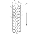
- FIG. 2 is a diagram showing the overall configuration of the stent 100. As shown in FIG.
- the stent 100 is formed by weaving wires and has a cylindrical shape.
- the stent 100 is indwelled in a digestive system body lumen such as a bile duct, esophagus, duodenum, small intestine, large intestine, etc., and is used mainly for the purpose of expanding and maintaining the lumen.
- a digestive system body lumen such as a bile duct, esophagus, duodenum, small intestine, large intestine, etc.
- the stent 100 of this embodiment is not a so-called covered stent whose outer peripheral surface side is covered with a resin film or the like, but an uncovered stent that is not covered with a film or the like.
- the stent 100 can also be used as a covered stent by being covered with a resin film or the like.
- first direction A1 one of the longitudinal axis directions (axial directions) A of the stent 100
- second direction A2 one of the longitudinal axis directions A of the stent 100
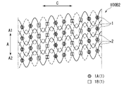
- FIG. 3 is a developed view of the stent 100 deployed in the circumferential direction C.
- the stent 100 is formed in the shape of a circular tube having meshes on its peripheral surface by wires W that extend obliquely in the circumferential direction C while repeatedly bending.
- the stent 100 has a plurality of straight crossing portions 1 and a plurality of hooking portions 2 .
- FIG. 4 is an exploded view of stent 100 including an enlarged partial view.
- the straight line crossing portion 1 is formed by the straight line portions 10 of the wires W crossing each other.
- the straight portion 10 is a substantially straight portion of the wire W and includes a gently curved portion.
- the engaging portion (entangled portion) 2 is formed by intersecting the mountain-shaped bent portion 3 and the valley-shaped bent portion 4 .
- the mountain-shaped bent portion (mountain) 3 is a convex portion in which the wire W extending obliquely in the circumferential direction C is folded back in the longitudinal axis direction A and convexes in the first direction A1.
- the valley-shaped bent portion (trough) 4 is a convex portion (concave in the first direction A1 side) in which the wire W extending in the circumferential direction is folded back in the longitudinal direction A and bent in the second direction A2 side (concave in the first direction A1 side). concave).
- the mountain-shaped bent portion 3 and the valley-shaped bent portion 4 intersect each other in a hook shape, so that the mountain-shaped bent portion 3 and the valley-shaped bent portion 4 are connected so as to be relatively movable although they cannot be separated. be done.
- the first regions E1 in which the plurality of straight line crossing portions 1 are arranged and the second regions E2 in which the plurality of engaging portions 2 are arranged are alternately arranged in the longitudinal axis direction A.
- the first region E1 is spirally arranged along the longitudinal axis direction A.
- the second region E2 is spirally arranged along the longitudinal axis direction A.
- the end region E3 of the stent 100 on the second direction A2 side is arranged parallel to the circumferential direction C without the valley-shaped bends 4 intersecting the mountain-shaped bends 3 .
- the end region (not shown) of the stent 100 on the first direction A1 side is arranged parallel to the circumferential direction C without the mountain-shaped bent portions 3 intersecting the valley-shaped bent portions 4 .
- First engagement portion 21 A “first mountain 31 ”, which is the mountain-shaped bent portion 3 , continues on the first direction A ⁇ b>1 side of the first straight portion 11 .
- the first peak 31 intersects with the first valley 41 that is the valley-shaped bent portion 4 to form the “first engaging portion 21 ” that is the engaging portion 2 .
- the first crest 31 and the first valley 41 are located at the first intersection C1 and the second intersection closer to the central straight intersection 1A than the first intersection C1. It intersects with the part C2.
- the first crest 31 passes through the outer side of the first valley 41 in the radial direction R.
- the first crest 31 passes through the inner side of the first valley 41 in the radial direction R.
- the second peak 32 intersects with the second valley 42 that is the valley-shaped bent portion 4 to form the “second hooking portion 22 ” that is the hooking portion 2 .
- the second crest 32 and the second valley 42 are located at a sixth intersection closer to the central straight intersection 1A than the fifth intersection C5 and the fifth intersection C5. It intersects with the part C6.
- the second peak 32 passes inside the second valley 42 in the radial direction R.
- the second peak 32 passes outside the second valley 42 in the radial direction R.
- the third valley 43 intersects with the third peak 33 that is the mountain-shaped bent portion 3 to form the “third engaging portion 23 ” that is the engaging portion 2 .
- the third crest 33 and the third valley 43 are closer to the central straight intersection 1A than the fourth intersection C4 and the fourth intersection C4. It intersects with the part C3.
- the third valley 43 passes inside the third crest 33 in the radial direction R at the third crossing portion C3.
- the third valley 43 passes outside the third crest 33 in the radial direction R at the fourth crossing portion C4.
- the fourth valley 44 intersects with the fourth peak 34 that is the mountain-shaped bent portion 3 to form the "fourth hooking portion 24" that is the hooking portion 2. As shown in FIG.
- the fourth crest 34 and the fourth valley 44 are closer to the central straight intersection 1A than the eighth intersection C8 and the eighth intersection C8. It intersects with the part C7.
- the fourth valley 44 passes outside the fourth crest 34 in the radial direction R at the seventh intersection C7.
- the fourth valley 44 passes inside the fourth crest 34 in the radial direction R at the fourth crossing portion C4.
- the first engaging portion 21 and the second engaging portion 22 are arranged at different positions in the longitudinal axis direction A. As shown in FIG. Specifically, the second engaging portion 22 is arranged on the first direction A1 side of the first engaging portion 21 in the longitudinal axis direction A. As shown in FIG. Also, the first engaging portion 21 is arranged in the longitudinal axis direction A between the second engaging portion 22 and the central straight line intersection portion 1A.
- the third engaging portion 23 and the fourth engaging portion 24 are arranged at different positions in the longitudinal axis direction A. Specifically, the third engaging portion 23 is arranged on the first direction A1 side of the fourth engaging portion 24 in the longitudinal axis direction A. As shown in FIG. Further, the third engaging portion 23 is arranged between the central straight line intersection portion 1A and the fourth engaging portion 24 in the longitudinal axis direction A. As shown in FIG.
- the central straight-line intersection portion 1A is arranged between the first engaging portion 21 and the second engaging portion 22 in the circumferential direction C. Further, the central straight line intersection portion 1A is arranged between the third engaging portion 23 and the fourth engaging portion 24 in the circumferential direction C. As shown in FIG.
- the first crest 31, the first straight portion 11, and the third valley 43 are continuous parts of the wire W extending zigzag along the circumferential direction C, and are parts of the wire W indicated by broken lines in FIG. .
- the wire W indicated by the dashed line in FIG. 4 is also referred to as "first wire W1".
- the second crest 32, the second straight portion 12, and the fourth valley 44 are continuous parts of the wire W extending zigzag along the circumferential direction C, and are parts of the wire W indicated by solid lines in FIG. be.
- the wire W indicated by the solid line in FIG. 4 is also referred to as "second wire W2".
- the first wire W1 and the second wire W2 may be one continuous wire, or may be different wires.
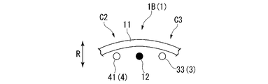
- FIG. 5 is a diagram showing intersections of the first straight portion 11 and other wires W.
- the first crest 31 extending in the first direction A1 passes inside the first valley 41 in the radial direction R at the second crossing portion C2.
- the third valley 43 continuous in the second direction A2 passes inside the third peak 33 in the radial direction R at the third intersecting portion C3. Therefore, as shown in FIG. 5, the first straight portion 11 sandwiched between the second crossing portion C2 and the third crossing portion C3 has a convex shape.
- the frictional force of the wires W intersecting at the second crossing portion C2, the third crossing portion C3 and the central straight crossing portion 1A increases, and the stent 100 tends to maintain its bent state.
- the operator inserts the insertion portion 210 of the endoscope 200 into the patient's body cavity through a natural opening such as the mouth. At that time, the operator bends the bending portion 212 by operating the knob 223 or the like as necessary.
- the operator passes the guidewire through the treatment instrument channel 230 of the endoscope 200 and inserts the guidewire into the bile duct while observing with the endoscope 200 . Subsequently, the operator operates the guidewire under X-ray fluoroscopy to break through the narrowed site in the bile duct, and moves the distal end of the guidewire to the liver side of the narrowed site (target position).
- the operator inserts the proximal end of the guide wire protruding from the forceps plug 225 of the endoscope 200 into the through hole of the tip 130 of the stent delivery system 150 .
- the operator advances the stent delivery system 150 along the guidewire by pushing the stent delivery system 150 while holding the guidewire.
- the distal end of stent delivery system 150 protrudes from the distal end of treatment instrument channel 230 of endoscope 200 .
- the operator advances and retracts the stent delivery system 150 to determine the indwelling position of the stent 100 . Note that the operator may insert the stent delivery system 150 into the treatment instrument channel 230 without using a guide wire.
- the operator After determining the target position of the stent 100 , the operator retracts the outer cylinder member 110 with respect to the inner cylinder member 120 . As a result, as shown in FIG. 1, the stent 100 is gradually exposed and expanded from the distal end side.
- the stent 100 When the stent 100 is completely exposed, the stent 100 expands as a whole and the inner diameter of the stent 100 becomes larger than the outer diameter of the inner tubular member 120 . Along with this, the locking between the stent 100 and the inner tubular member 120 is released.
- the stent 100 After the locking between the stent 100 and the inner tubular member 120 is released, when the operator retracts the inner tubular member 120 , the stent 100 remains at the indwelling position and the inner tubular member 120 is removed from the stent 100 .
- the placement procedure of the stent 100 is completed.
- the stent 100 has a plurality of engaging portions 2 and has high shape followability even when bent. Further, as shown in FIG. 5, since the first straight portion 11 sandwiched between the second intersection C2 and the third intersection C3 is convex, the second intersection C2, the third intersection C3 and the central straight line The frictional force of the wires W intersecting at the crossing portion 1A is increased, and the stent 100 tends to maintain its bent state. As a result, stent 100 is easy to bend and easy to maintain in a bent state.
- the second regions E2 are arranged in a spiral shape, so the stent 100 can be knitted without arranging the straight-line intersections 1 in the second regions E2. That is, in the stent 100, it is not necessary to arrange the linear crossing portion 1 at a position adjacent to the engaging portion 2 in the circumferential direction C. Therefore, in the second region E2, the stent 100 has only the hooking portions 2 having high conformability, and is easy to bend.
- the first regions E1 where the straight crossing portions 1 where the frictional force (locking force) of the intersecting wires W is large are arranged alternately with the second regions E2 in the longitudinal axis direction A. As shown in FIG. Therefore, the stent 100 can preferably maintain its curved shape.
- the crossing manner of the wires W is not limited to the crossing manner shown in FIG.
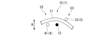
- FIG. 6 is a diagram showing a modification of the intersecting manner of the wires W.
- FIG. 7 is a diagram showing intersections of the first straight portion 11 and another wire W in the modification.
- the first linear portion 11 has the first peak 31 continuous in the first direction A1 passing outside the first valley 41 in the radial direction R at the second crossing portion C2. do.
- the third valley 43 continuous in the second direction A2 passes outside the third peak 33 in the radial direction R at the third intersecting portion C3. Therefore, as shown in FIG.
- the first straight portion 11 sandwiched between the second crossing portion C2 and the third crossing portion C3 has an arc shape.
- the frictional force of the wires W intersecting at the second crossing portion C2, the third crossing portion C3 and the central straight crossing portion 1B becomes smaller than in the above embodiment, and the stent 100 becomes more bendable.
- FIGS. 8A and 8B are diagrams showing another modification of the intersecting manner of the wires W.
- FIG. FIG. 9 is a diagram showing intersections of the first straight portion 11 and another wire W in another modification.
- the first linear portion 11 has the first peak 31 continuous in the first direction A1 passing outside the first valley 41 in the radial direction R at the second crossing portion C2. do.
- the third valley 43 continuous in the second direction A2 passes inside the third peak 33 in the radial direction R at the third intersecting portion C3.
- the frictional force of the wires W intersecting at the second crossing portion C2, the third crossing portion C3, and the central straight crossing portion 1C is smaller than in the above embodiment, and larger than that in Modification 1-1. Become.
- a second embodiment of the present invention will be described with reference to FIG. In the following description, the same reference numerals are given to the same configurations as those already described, and redundant descriptions will be omitted.
- a stent 100B according to the second embodiment is housed in a stent delivery system 150, like the stent 100 according to the first embodiment.
- the intersections of the wires W at the straight crossing portion 1 and the four engaging portions 2 connected to the straight crossing portion 1 were the same at any location.
- the crossing pattern of the wire W at the straight crossing portion 1 and the four hooking portions 2 connected to the straight crossing portion 1 differs depending on the location.
- first straight line intersection portion 1A The central straight line intersection portion 1A of the stent 100 according to the first embodiment will be referred to as "first straight line intersection portion 1A" in the following description.
- the first straight line portion 11 forming the first straight line intersection portion 1A has a first peak 31 extending in the first direction A1 and a first valley 41 at the second intersection portion C2. in the radial direction R.
- the third valley 43 extending in the second direction A2 passes inside the third peak 33 in the radial direction R at the third intersection portion C3.
- the central straight-line intersection 1B shown in Modification 1-1 of the first embodiment will be referred to as "second straight-line intersection 1B" in the following description.
- the first straight line portion 11 forming the second straight line intersection portion 1B has a first peak 31 extending in the first direction A1 and a first valley at the second intersection portion C2. 41 in the radial direction R.
- the third valley 43 continuing on the second direction A2 side passes through the outside of the third crest 33 in the radial direction R at the third intersection portion C3. .
- the second straight-line crossing portion 1B may be a straight-line crossing portion 1 having a different wire W crossing mode such as the central straight-line crossing portion 1C shown in Modification 1-2.
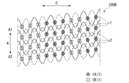
- FIG. 10 is a developed view of the stent 100B deployed in the circumferential direction C.
- the stent 100B has a plurality of linear crossing portions 1 and a plurality of hooking portions 2, like the stent 100 according to the first embodiment.
- the plurality of straight-line intersections 1 includes a first straight-line intersection 1A and a second straight-line intersection 1B.
- the first straight-line intersection portion 1A is arranged continuously in the longitudinal axis direction A. Two or three first straight crossing portions 1A are continuously arranged in the circumferential direction C. As shown in FIG. Moreover, the second straight-line intersection portion 1B is arranged continuously in the longitudinal axis direction A. As shown in FIG. Two or three second straight-line intersection portions 1B are continuously arranged in the circumferential direction C. As shown in FIG. Further, the first straight line intersection portions 1A and the second straight line intersection portions 1B are alternately arranged in the circumferential direction C. As shown in FIG.
- the number of first straight-line intersections 1A and the number of second straight-line intersections 1B are substantially equal.
- the first straight crossing portion 1A where the frictional force of the crossing wires W is high is arranged continuously in the longitudinal axis direction A.
- the second straight crossing portion 1B where the frictional force of the crossing wires W is low is arranged continuously in the longitudinal axis direction A.
- the first straight line intersection portions 1A and the second straight line intersection portions 1B are alternately arranged in the circumferential direction C. As shown in FIG. As a result, the stent 100B can achieve both high shape followability and high shape retention.
- FIG. 11 is a diagram showing a stent 100B1 that is a modification of the arrangement of the first straight crossing portion 1A and the second straight crossing portion 1B.
- the number of first straight crossings 1A is greater than the number of second straight crossings 1B. Therefore, in the stent 100B1, the frictional force of the intersecting wires W is higher than in the stent 100B, and the stent 100B1 is less likely to collapse in the longitudinal direction A.
- FIG. 12 is a diagram showing a stent 100B2 that is a modification of the arrangement of the first straight line crossing portion 1A and the second straight line crossing portion 1B.
- 1 A of 1st straight line intersection parts are arrange
- two second straight-line intersection portions 1B are continuously arranged in the circumferential direction C.
- FIG. 13 is a diagram showing a stent 100B3 that is a modified example of the arrangement of the first straight line intersection portion 1A and the second straight line intersection portion 1B.
- the first straight line intersection portion 1A and the second straight line intersection portion 1B are arranged alternately one by one in the circumferential direction C.
- Stent 100B3 has higher shape followability and shape retention than stent 100B.
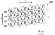
- the stent 100C according to the third embodiment differs from the stent 100B according to the second embodiment only in the arrangement of the first straight intersection portion 1A and the second straight intersection portion 1B.
- FIG. 14 is a developed view of the stent 100C deployed in the circumferential direction C.
- the stent 100C has a plurality of linear crossing portions 1 and a plurality of hooking portions 2, like the stent 100 according to the first embodiment.
- the plurality of straight-line intersections 1 includes a first straight-line intersection 1A and a second straight-line intersection 1B.
- the first straight-line intersection portion 1A and the second straight-line intersection portion 1B are alternately arranged one by one in the longitudinal axis direction A. Also, the first straight line crossing portion 1A and the second straight line crossing portion 1B are alternately arranged in the circumferential direction C one by one.
- the first straight crossing portion 1A where the frictional force of the crossing wires W is high and the second straight crossing portion 1B where the frictional force of the crossing wires W is low are arranged in the longitudinal axis direction A. and in the circumferential direction C, it is possible to achieve both high shape followability and high shape maintainability.
- FIG. 15 is a diagram showing a stent 100C1 that is a modification of the arrangement of the first straight crossing portion 1A and the second straight crossing portion 1B.
- the first straight crossing portion 1A and the second straight crossing portion 1B are alternately arranged in the longitudinal axis direction A one by one.
- the stent 100C1 includes a second region E2A in which one first straight crossing portion 1A and two continuous second straight crossing portions 1B are arranged in the circumferential direction C, two continuous first straight crossing portions 1A and one and a second region E2B arranged in the circumferential direction C with the second straight intersection portion 1B.
- the second regions E2A and the second regions E2B are alternately arranged in the longitudinal direction A one by one.
- the stent 100C1 has higher shape followability than the stent 100C.
- FIG. 16 is a diagram showing a stent 100C2 that is a modification of the arrangement of the first straight crossing portion 1A and the second straight crossing portion 1B.
- Three or four first straight crossing portions 1A are continuously arranged in the circumferential direction C.
- three or four second straight-line intersection portions 1B are continuously arranged in the circumferential direction C.
- the stent 100C2 can achieve both high shape followability and high shape retention.
- a fourth embodiment of the present invention will be described with reference to FIG. In the following description, the same reference numerals are given to the same configurations as those already described, and redundant descriptions will be omitted.
- a stent 100D according to the fourth embodiment differs from the stent 100B according to the second embodiment only in the arrangement of the first straight intersection portion 1A and the second straight intersection portion 1B.
- FIG. 17 is a developed view of the stent 100D deployed in the circumferential direction C.
- the stent 100D has a plurality of linear crossing portions 1 and a plurality of hooking portions 2, like the stent 100 according to the first embodiment.
- the plurality of straight-line intersections 1 includes a first straight-line intersection 1A and a second straight-line intersection 1B.
- the first straight-line intersections 1A are arranged continuously in the circumferential direction C.
- the second straight-line intersection portion 1B is arranged continuously in the circumferential direction C.
- the first straight line intersection portions 1A and the second straight line intersection portions 1B are alternately arranged in the longitudinal axis direction A. As shown in FIG.
- the first straight crossing portions 1A where the frictional force of the crossing wires W is high are arranged continuously in the circumferential direction C, so that it is easy to maintain a certain shape retention.
- the stent 100D can partially retain a portion having a very high shape followability while maintaining a certain shape retention property.
- FIG. 18 is a diagram showing a stent 100D1 that is a modification of the arrangement of the first straight crossing portion 1A and the second straight crossing portion 1B.
- the first straight crossing portions 1A are alternately arranged in the circumferential direction C.
- the second straight crossing portion 1B is not arranged continuously in the circumferential direction C.
- the second straight line crossing portions 1B and the first straight line crossing portions 1A are alternately arranged in the circumferential direction C one by one.
- the stent 100D1 can partially retain a portion with extremely high shape followability while maintaining constant shape retention.
- FIG. 19 is a diagram showing a stent 100D2 that is a modification of the arrangement of the first straight crossing portion 1A and the second straight crossing portion 1B.
- the first straight crossing portions 1A are arranged continuously in the circumferential direction C.
- the second straight crossing portion 1B is not continuously arranged in the circumferential direction C.
- the five continuous second straight line intersections 1B are arranged adjacent to the five continuous first straight line intersections 1A in the circumferential direction C. As shown in FIG.
- the part where the second straight crossing part 1B where the frictional force of the intersecting wires W is low is arranged intensively becomes a part that is easily curved.
- the stent 100D2 can partially enhance shape followability while maintaining high shape retention in a curved state.
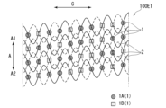
- a fifth embodiment of the present invention will be described with reference to FIG. In the following description, the same reference numerals are given to the same configurations as those already described, and redundant descriptions will be omitted.
- a stent 100E according to the fourth embodiment differs from the stent 100B according to the second embodiment only in the arrangement of the first straight intersection portion 1A and the second straight intersection portion 1B.
- FIG. 20 is a developed view of the stent 100E deployed in the circumferential direction C.
- the stent 100E has a plurality of linear crossing portions 1 and a plurality of hooking portions 2, like the stent 100 according to the first embodiment.
- the plurality of straight-line intersections 1 includes a first straight-line intersection 1A and a second straight-line intersection 1B.
- the two first straight-line intersections 1A that are continuous in the circumferential direction C are arranged spirally along the longitudinal axis direction A. Further, three second straight-line intersection portions 1B continuous in the circumferential direction C are arranged spirally along the longitudinal axis direction A. As shown in FIG.
- the stent 100E since the first straight line crossing portion 1A and the second straight crossing portion 1B are arranged in a spiral shape along the longitudinal axis direction A, the shape followability against twisting is greatly enhanced. be able to.
- FIG. 21 is a diagram showing a stent 100E1 that is a modification of the arrangement of the first straight crossing portion 1A and the second straight crossing portion 1B.
- Two first straight crossing portions 1A that are continuous in the circumferential direction C are arranged spirally along the longitudinal axis direction A.
- Two second straight line intersection portions 1B that are continuous in the circumferential direction C are arranged spirally along the longitudinal axis direction A.
- FIG. 21 is a diagram showing a stent 100E1 that is a modification of the arrangement of the first straight crossing portion 1A and the second straight crossing portion 1B.
- FIG. 22 is a diagram showing a stent 100E2 that is a modification of the arrangement of the first straight crossing portion 1A and the second straight crossing portion 1B.
- the three first straight intersection portions 1A that are continuous in the circumferential direction C are arranged spirally along the longitudinal axis direction A.
- three second straight-line intersection portions 1B continuous in the circumferential direction C are arranged spirally along the longitudinal axis direction A.
- FIG. 1A that are continuous in the circumferential direction C are arranged spirally along the longitudinal axis direction A.
- FIG. 23 is a diagram showing a stent 100E3 that is a modification of the arrangement of the first straight crossing portion 1A and the second straight crossing portion 1B.
- the three first straight intersection portions 1A that are continuous in the circumferential direction C are arranged spirally along the longitudinal axis direction A.
- one second straight line intersection portion 1B continuous in the circumferential direction C is arranged spirally along the longitudinal axis direction A.
- FIG. 24 is a diagram showing a stent 100E4 that is a modification of the arrangement of the first straight crossing portion 1A and the second straight crossing portion 1B.
- Three or two first straight crossing portions 1A that are continuous in the circumferential direction C are arranged spirally along the longitudinal axis direction A.
- Two second straight line intersection portions 1B that are continuous in the circumferential direction C are arranged spirally along the longitudinal axis direction A.
- the plurality of engaging portions 2 are arranged spirally along the longitudinal axis direction A. As shown in FIG. The distance D in the longitudinal axis direction A between the engaging portions 2 adjacent in the circumferential direction C was substantially the same. However, the arrangement mode of the plurality of engaging portions 2 is not limited to this. 25A and 25B are diagrams showing a modification of the arrangement of the plurality of engaging portions 2. FIG. The distance D in the longitudinal direction A between the engaging portions 2 adjacent to each other in the circumferential direction C does not have to be a constant distance. Moreover, the plurality of engaging portions 2 may be arranged in a spiral shape as a whole. The same is true for the plurality of straight line intersections 1 .
- the plurality of engaging parts 2 includes a fifth engaging part 25, a sixth engaging part 26, and a seventh engaging part 27.
- the sixth engaging portion 26 is adjacent to the fifth engaging portion 25 in the circumferential direction C.
- the seventh engaging portion 27 is adjacent to the sixth engaging portion 26 in the circumferential direction C.
- the positions of the fifth engaging portion 25 and the sixth engaging portion 26 in the longitudinal direction A are substantially the same, and the positions of the sixth engaging portion 26 and the seventh engaging portion 27 in the longitudinal direction A are different.
- the plurality of straight-line intersections 1 includes a third straight-line intersection 13 , a fourth straight-line intersection 14 , and a fifth straight-line intersection 15 .
- the fourth straight intersection portion 14 is adjacent to the third straight intersection portion 13 in the circumferential direction C.
- the fifth straight line intersection portion 15 is adjacent to the fourth straight line intersection portion 14 in the circumferential direction C.
- the positions of the longitudinal axis direction A of the third straight line intersection portion 13 and the fourth straight line intersection portion 14 are substantially the same, and the positions of the longitudinal axis direction A of the fourth straight line intersection portion 14 and the fifth straight line intersection portion 15 are different. .
- the present invention can be applied to stents formed by weaving wires or the like.
- Endoscope system 200 Endoscope 150 Stent delivery system 110 Outer cylinder member 120 Inner cylinder member 130 Chip 100, 100B, 100C, 100D, 100E Stent 1 Straight line intersection 10 Straight line 11 First straight line 12 Second straight line 1A Central straight-line intersection, first straight-line intersection 1B Central straight-line intersection, second straight-line intersection 1C Central straight-line intersection 13 Third straight-line intersection 14 Fourth straight-line intersection 15 Fifth straight-line intersection 2 ) 21 First engaging portion 22 Second engaging portion 23 Third engaging portion 24 Fourth engaging portion 25 Fifth engaging portion 26 Sixth engaging portion 27 Seventh engaging portion 3 Mountain-shaped bent portion (mountain) 31 First mountain 32 Second mountain 33 Third mountain 34 Fourth mountain 4 Valley-shaped bend (valley) 41 First valley 42 Second valley 43 Third valley 44 Fourth valley
Landscapes
- Health & Medical Sciences (AREA)
- Engineering & Computer Science (AREA)
- Biomedical Technology (AREA)
- Cardiology (AREA)
- Oral & Maxillofacial Surgery (AREA)
- Transplantation (AREA)
- Heart & Thoracic Surgery (AREA)
- Vascular Medicine (AREA)
- Life Sciences & Earth Sciences (AREA)
- Animal Behavior & Ethology (AREA)
- General Health & Medical Sciences (AREA)
- Public Health (AREA)
- Veterinary Medicine (AREA)
- Media Introduction/Drainage Providing Device (AREA)
Abstract
A stent according to the present invention is formed by weaving wires, said stent comprising: a plurality of straight intersections that are constituted by intersections of straight portions of at least two wires and that are disposed so as to be adjacent to each other in the circumferential direction of the stent; and a plurality of engagement portions that are constituted by intersections of peak-shaped bent portions each formed by the wire being bent so as to protrude toward a first direction side which is one side in the longitudinal direction of the stent and valley-shaped bent portions each formed by the wire being bent so as to protrude toward a second direction side which is the other side in the longitudinal direction and that are disposed so as to be adjacent to each other in the circumferential direction of the stent, wherein the engagement portions and the straight intersections are alternately disposed in the longitudinal direction.
Description
本発明は、ステントおよびステントデリバリーシステムに関する。
The present invention relates to stents and stent delivery systems.
消化管等に生じた狭窄や閉塞(以下、「狭窄等」と称する。)に対して、ステントを留置して拡張する手技が知られている。ステントを狭窄等に留置するためにステントデリバリーシステムが用いられている。ステントデリバリーシステムは、内視鏡の処置具チャネルを挿通してステントを狭窄等まで搬送する。
A procedure is known in which a stent is placed and expanded for stenosis or obstruction (hereinafter referred to as "stenosis, etc.") that occurs in the digestive tract. A stent delivery system is used to place a stent in a stenosis or the like. A stent delivery system passes through a treatment instrument channel of an endoscope to deliver a stent to a stenosis or the like.
例えば特許文献1に記載されたステントは、1本のワイヤを治具に取り付けたピンに巻きかけてフェンス状に編むことで構成される。当該ステントは、二つの湾曲形状が互いに掛け合わされた箇所(かみ合わせ部60)が形成されるため、曲げられた場合であっても形状追従性が高く、留置する管腔内の地形に適合しやすいという特徴を有する。
For example, the stent described in Patent Document 1 is constructed by winding a single wire around a pin attached to a jig and weaving it like a fence. Since the stent has a portion (interlocking portion 60) where two curved shapes are interlocked with each other, it has high shape followability even when it is bent, and easily adapts to the topography of the lumen in which it is placed. It has the characteristics of
特許文献1に記載されたステントは、1本のワイヤで編み込んで構成されるため、直線状のワイヤが互いに交差する部分(直線交差部70)がステントの周方向においてかみ合わせ部60に隣接する部分に位置している。ステントが曲げられる際に、かみ合わせ部60は追従して湾曲可能であるが、直線交差部70は曲げに反発する力(アキシャルフォース)を生じるため、ステント全体としての形状追従性を損なっている。特に、管腔内の形状が大きく屈曲している箇所では、ステントの留置が容易に行えない、または留置ができたとしても、管腔がステントの形状に倣おうとする状態になり管腔に負担をかけたり、ステントが留置位置から移動してしまうといった問題が生じ得る。
Since the stent described in Patent Document 1 is constructed by weaving one wire, the portion where the straight wires cross each other (straight line intersection portion 70) is the portion adjacent to the meshing portion 60 in the circumferential direction of the stent. located in When the stent is bent, the interlocking portions 60 can bend accordingly, but the linear intersection portions 70 generate a force (axial force) that repels the bending, which impairs the shape followability of the stent as a whole. In particular, in places where the shape of the lumen is greatly curved, it is difficult to place the stent, or even if it can be placed, the lumen will try to follow the shape of the stent, causing a burden on the lumen. Problems can occur, such as overheating and the stent moving out of its deployed position.
上記事情を踏まえ、本発明は、曲げやすく、かつ、曲がった状態を維持しやすいステントおよび当該ステントを備えたステントデリバリーシステムを提供することを目的とする。
In light of the above circumstances, an object of the present invention is to provide a stent that is easy to bend and maintain a bent state, and a stent delivery system that includes the stent.
上記課題を解決するために、この発明は以下の手段を提案している。
本発明の第一の態様に係るステントは、ワイヤを編み込んで形成されたステントであって、少なくとも2つの前記ワイヤの直線部が交差することで構成され、前記ステントの周方向において互いに隣接するように配置されている複数の直線交差部と、前記ワイヤが前記ステントの長手軸方向の一方である第一方向の側に屈曲して凸となる山型屈曲部と、前記ワイヤが前記長手軸方向の他方である第二方向の側に屈曲して凸となる谷型屈曲部と、が交差することで構成され、前記ステントの前記周方向において互いに隣接するように配置されている複数の掛合部と、を備え、前記掛合部と前記直線交差部は、前記長手軸方向において交互に配置される。 In order to solve the above problems, the present invention proposes the following means.
A stent according to a first aspect of the present invention is a stent formed by weaving wires, wherein at least two straight portions of the wires intersect so that they are adjacent to each other in the circumferential direction of the stent. a plurality of straight crossing portions arranged in the longitudinal direction of the stent, a mountain-shaped bending portion in which the wire is bent in a first direction that is one of the longitudinal axis directions of the stent and becomes convex, and the wire is in the longitudinal axis direction A plurality of engaging portions arranged so as to be adjacent to each other in the circumferential direction of the stent. and, wherein the engaging portions and the linear intersection portions are alternately arranged in the longitudinal axis direction.
本発明の第二の態様に係るトデリバリーシステムは、操作部と、前記操作部から遠位側で延びるように構成される外筒部材と、前記操作部から遠位側で延びるように構成され、前記外筒部材の内側にある内筒部材と、前記外筒部材と前記内筒部材の間に収容される上記ステントと、を備え、前記操作部は、前記外筒部材または前記内筒部材を長手方向に移動させることで前記ステントを留置するよう構成される。
A delivery system according to a second aspect of the present invention comprises an operating portion, an outer cylinder member configured to extend distally from the operating portion, and an outer cylinder member configured to extend distally from the operating portion. , an inner tubular member located inside the outer tubular member, and the stent accommodated between the outer tubular member and the inner tubular member, wherein the operation section is the outer tubular member or the inner tubular member. longitudinally displacing the stent.
本発明のステントは、曲げやすく、かつ、曲がった状態を維持しやすい。
The stent of the present invention is easy to bend and easy to maintain the bent state.
(第一実施形態)
本発明の第一実施形態に係るステント100を備える内視鏡システム300について、図1から図5を参照して説明する。図1は、内視鏡システム300の全体構成を示す図である。 (First embodiment)
An endoscope system 300 having astent 100 according to a first embodiment of the invention will be described with reference to FIGS. 1 to 5. FIG. FIG. 1 is a diagram showing the overall configuration of an endoscope system 300. As shown in FIG.
本発明の第一実施形態に係るステント100を備える内視鏡システム300について、図1から図5を参照して説明する。図1は、内視鏡システム300の全体構成を示す図である。 (First embodiment)
An endoscope system 300 having a
[内視鏡システム300]
内視鏡システム300は、内視鏡200と、内視鏡200のチャネルに挿通されるステントデリバリーシステム150と、を備える。 [Endoscope system 300]
The endoscope system 300 includes anendoscope 200 and a stent delivery system 150 inserted through a channel of the endoscope 200. FIG.
内視鏡システム300は、内視鏡200と、内視鏡200のチャネルに挿通されるステントデリバリーシステム150と、を備える。 [Endoscope system 300]
The endoscope system 300 includes an
[内視鏡200]
内視鏡200は、公知の側視型の軟性内視鏡であり、長尺の挿入部210と、挿入部210の基端部に設けられた操作部220と、を備える。なお、内視鏡200は直視型の軟性内視鏡であってもよい。 [Endoscope 200]
Theendoscope 200 is a known side-viewing flexible endoscope, and includes an elongated insertion section 210 and an operation section 220 provided at the proximal end of the insertion section 210 . Note that the endoscope 200 may be a direct-view flexible endoscope.
内視鏡200は、公知の側視型の軟性内視鏡であり、長尺の挿入部210と、挿入部210の基端部に設けられた操作部220と、を備える。なお、内視鏡200は直視型の軟性内視鏡であってもよい。 [Endoscope 200]
The
挿入部210は、先端部に設けられた先端硬質部211と、先端硬質部211の基端側に設けられた湾曲操作可能な湾曲部212と、湾曲部212の基端側に設けられた可撓管部213と、を有する。先端硬質部211の側面には、ライトガイド215およびCCDを有する撮像ユニット216が外部に露出した状態で設けられている。
The insertion section 210 includes a distal rigid portion 211 provided at the distal end portion, a bendable bending portion 212 provided at the proximal end side of the distal rigid portion 211, and a flexible portion provided at the proximal end side of the bending portion 212. and a flexible tube portion 213 . An imaging unit 216 having a light guide 215 and a CCD is provided on the side surface of the distal end rigid portion 211 in a state of being exposed to the outside.
挿入部210には、ステントデリバリーシステム150等の内視鏡用処置具を挿通させるための処置具チャネル230が形成されている。処置具チャネル230の先端部230aは、先端硬質部211の側面において開口している。処置具チャネル230の基端部は、操作部220まで延びている。
The insertion portion 210 is formed with a treatment instrument channel 230 through which an endoscopic treatment instrument such as the stent delivery system 150 is inserted. A distal end portion 230 a of the treatment instrument channel 230 is open on the side surface of the distal end rigid portion 211 . A proximal end portion of the treatment instrument channel 230 extends to the operating portion 220 .
処置具チャネル230の先端硬質部211には、起上台214が設けられている。起上台214の基端部は、先端硬質部211に回転可能に支持されている。起上台214の先端部に固定された不図示の起上台操作ワイヤは、挿入部210内を通して基端側に延びている。
A riser 214 is provided on the distal end hard portion 211 of the treatment instrument channel 230 . A base end portion of the raising base 214 is rotatably supported by the distal end rigid portion 211 . An elevator operating wire (not shown) fixed to the distal end of the elevator 214 extends through the insertion section 210 toward the proximal end.
湾曲部212は、上下方向や左右方向に湾曲自在に構成されている。湾曲部212の先端側に操作ワイヤの先端が固定されている。操作ワイヤは挿入部210内を通して操作部220まで延びている。
The bending portion 212 is configured to be freely bendable in the vertical and horizontal directions. The distal end of the operation wire is fixed to the distal end side of the bending portion 212 . The operation wire extends through the insertion portion 210 to the operation portion 220 .
操作部220の基端側には、操作ワイヤを操作するノブ223や撮像ユニット216等を操作するスイッチ224が設けられている。使用者は、ノブ223を操作することで湾曲部212を所望の方向に湾曲させることができる。
A knob 223 for operating the operation wire and a switch 224 for operating the imaging unit 216 and the like are provided on the proximal end side of the operation section 220 . The user can bend the bending portion 212 in a desired direction by operating the knob 223 .
操作部220の先端側には、処置具チャネル230に連通する鉗子口222が設けられている。使用者は、鉗子口222からステントデリバリーシステム150等の内視鏡用処置具を挿入することができる。鉗子口222には体液の漏れを防ぐために鉗子栓225が取り付けられる。
A forceps port 222 that communicates with the treatment instrument channel 230 is provided on the distal end side of the operation portion 220 . A user can insert an endoscopic instrument such as the stent delivery system 150 through the forceps port 222 . A forceps plug 225 is attached to the forceps port 222 to prevent leakage of bodily fluids.
[ステントデリバリーシステム150]
ステントデリバリーシステム150は、全体として細長に形成され、ステント100と、外筒部材110と、内筒部材120と、操作部140を備える。 [Stent delivery system 150]
Thestent delivery system 150 is elongated as a whole and includes a stent 100 , an outer tubular member 110 , an inner tubular member 120 and an operating section 140 .
ステントデリバリーシステム150は、全体として細長に形成され、ステント100と、外筒部材110と、内筒部材120と、操作部140を備える。 [Stent delivery system 150]
The
外筒部材110は、樹脂等で筒状に形成されており、可撓性を有する。外筒部材110は、内視鏡200の処置具チャネル230を挿通可能である。
The outer cylindrical member 110 is made of resin or the like in a cylindrical shape and has flexibility. Outer cylinder member 110 can be inserted through treatment instrument channel 230 of endoscope 200 .
内筒部材120は、外筒部材110の内径よりも小さい外径を有し、外筒部材110の内部空間(ルーメン)に通すことができる。内筒部材120は、樹脂等で形成されており、可撓性を有する。内筒部材120の先端には、外筒部材110の外径よりも大きい外径を有するチップ130が設けられている。
The inner cylinder member 120 has an outer diameter smaller than the inner diameter of the outer cylinder member 110 and can be passed through the inner space (lumen) of the outer cylinder member 110 . The inner cylindrical member 120 is made of resin or the like and has flexibility. A tip 130 having an outer diameter larger than that of the outer cylinder member 110 is provided at the tip of the inner cylinder member 120 .
ステント100は、図1に示すように、ステントデリバリーシステム150の先端部に収容される。ステント100は、内部に内筒部材120が通されて縮径した状態で、内筒部材120と外筒部材110との間の隙間に収容される。
The stent 100 is housed at the distal end of the stent delivery system 150, as shown in FIG. The stent 100 is accommodated in the gap between the inner tubular member 120 and the outer tubular member 110 in a state in which the inner tubular member 120 is passed through the inside thereof and the diameter thereof is reduced.
操作部140は、外筒部材110および内筒部材120の基端側に接続し、外筒部材110を内筒部材120に対して相対的に長手方向に移動可能に構成される。操作者は操作部を操作することにより、外筒部材110が内筒部材120に対して移動させることで収容されたステント100を露出させた結果、ステント100が留置することができる。また、ステントを露出させている際に、操作者が外筒部材110が内筒部材120に対して逆の方向に移動させるよう操作することで、ステント100を再収容させることもできる。
The operation part 140 is connected to the base end sides of the outer cylinder member 110 and the inner cylinder member 120, and is configured to allow the outer cylinder member 110 to move relative to the inner cylinder member 120 in the longitudinal direction. By operating the operating portion, the operator moves the outer tube member 110 with respect to the inner tube member 120 to expose the accommodated stent 100, and as a result, the stent 100 can be placed. In addition, when the stent is exposed, the operator can move the outer tube member 110 in the opposite direction relative to the inner tube member 120, thereby allowing the stent 100 to be re-accommodated.
[ステント100]
図2は、ステント100の全体構成を示す図である。
ステント100は、ワイヤを編み込んで形成されており、円筒形状を有する。ステント100は、胆管、食道、十二指腸、小腸、大腸等の消化器系体内管腔等に留置され、主として管腔を拡張・保持する目的で使用される。 [Stent 100]
FIG. 2 is a diagram showing the overall configuration of thestent 100. As shown in FIG.
Thestent 100 is formed by weaving wires and has a cylindrical shape. The stent 100 is indwelled in a digestive system body lumen such as a bile duct, esophagus, duodenum, small intestine, large intestine, etc., and is used mainly for the purpose of expanding and maintaining the lumen.
図2は、ステント100の全体構成を示す図である。
ステント100は、ワイヤを編み込んで形成されており、円筒形状を有する。ステント100は、胆管、食道、十二指腸、小腸、大腸等の消化器系体内管腔等に留置され、主として管腔を拡張・保持する目的で使用される。 [Stent 100]
FIG. 2 is a diagram showing the overall configuration of the
The
本実施形態のステント100は、その外周面側を樹脂フィルム等で被覆したいわゆるカバードステントではなく、フィルム等で被覆されないアンカバードステントである。ただし、ステント100は、樹脂フィルム等で被覆してカバードステントとして用いることもできる。
The stent 100 of this embodiment is not a so-called covered stent whose outer peripheral surface side is covered with a resin film or the like, but an uncovered stent that is not covered with a film or the like. However, the stent 100 can also be used as a covered stent by being covered with a resin film or the like.
以降の説明において、ステント100の長手軸方向(軸方向)Aの一方を「第一方向A1」といい、ステント100の長手軸方向Aの他方を「第二方向A2」という。
In the following description, one of the longitudinal axis directions (axial directions) A of the stent 100 is called "first direction A1", and the other of the longitudinal axis directions A of the stent 100 is called "second direction A2".
図3は、ステント100を周方向Cに展開した展開図である。
ステント100は、屈曲を繰り返しながら周方向Cに傾いて延びるワイヤWにより、網目を周面に有する円管状に形成されている。ステント100は、複数の直線交差部1と、複数の掛合部2と、を有する。 FIG. 3 is a developed view of thestent 100 deployed in the circumferential direction C. As shown in FIG.
Thestent 100 is formed in the shape of a circular tube having meshes on its peripheral surface by wires W that extend obliquely in the circumferential direction C while repeatedly bending. The stent 100 has a plurality of straight crossing portions 1 and a plurality of hooking portions 2 .
ステント100は、屈曲を繰り返しながら周方向Cに傾いて延びるワイヤWにより、網目を周面に有する円管状に形成されている。ステント100は、複数の直線交差部1と、複数の掛合部2と、を有する。 FIG. 3 is a developed view of the
The
図4は、部分拡大図を含むステント100の展開図である。
直線交差部1は、ワイヤWの直線部10が直線交差して形成される。直線部10は、ワイヤWの略直線状の部分であり、ゆるやかに湾曲している部分も含む。 FIG. 4 is an exploded view ofstent 100 including an enlarged partial view.
The straightline crossing portion 1 is formed by the straight line portions 10 of the wires W crossing each other. The straight portion 10 is a substantially straight portion of the wire W and includes a gently curved portion.
直線交差部1は、ワイヤWの直線部10が直線交差して形成される。直線部10は、ワイヤWの略直線状の部分であり、ゆるやかに湾曲している部分も含む。 FIG. 4 is an exploded view of
The straight
掛合部(絡合部)2は、山型屈曲部3と、谷型屈曲部4とが交差して形成される。山型屈曲部(山)3は、周方向Cに傾いて延びるワイヤWが長手軸方向Aに折り返して屈曲し、第一方向A1側に凸となる凸部である。谷型屈曲部(谷)4は、周方向に傾いて延びるワイヤWが長手軸方向Aに折り返して屈曲し、第二方向A2側に凸となる凸部(第一方向A1側に凹となる凹部)である。掛合部2において、山型屈曲部3と谷型屈曲部4とがフック状に交差することで、山型屈曲部3と谷型屈曲部4とは、分離不能ではあるが相対移動可能に連結される。
The engaging portion (entangled portion) 2 is formed by intersecting the mountain-shaped bent portion 3 and the valley-shaped bent portion 4 . The mountain-shaped bent portion (mountain) 3 is a convex portion in which the wire W extending obliquely in the circumferential direction C is folded back in the longitudinal axis direction A and convexes in the first direction A1. The valley-shaped bent portion (trough) 4 is a convex portion (concave in the first direction A1 side) in which the wire W extending in the circumferential direction is folded back in the longitudinal direction A and bent in the second direction A2 side (concave in the first direction A1 side). concave). In the engaging portion 2, the mountain-shaped bent portion 3 and the valley-shaped bent portion 4 intersect each other in a hook shape, so that the mountain-shaped bent portion 3 and the valley-shaped bent portion 4 are connected so as to be relatively movable although they cannot be separated. be done.
図3に示すように、複数の直線交差部1が配置される第一領域E1と、複数の掛合部2が配置される第二領域E2とは、長手軸方向Aにおいて交互に配置される。第一領域E1は、長手軸方向Aに沿って螺旋状に配置される。また、第二領域E2は、長手軸方向Aに沿って螺旋状に配置される。
As shown in FIG. 3, the first regions E1 in which the plurality of straight line crossing portions 1 are arranged and the second regions E2 in which the plurality of engaging portions 2 are arranged are alternately arranged in the longitudinal axis direction A. The first region E1 is spirally arranged along the longitudinal axis direction A. As shown in FIG. In addition, the second region E2 is spirally arranged along the longitudinal axis direction A. As shown in FIG.
ステント100の第二方向A2側の端部領域E3は、谷型屈曲部4が山型屈曲部3と交差することなく、周方向Cに平行に配置される。また、ステント100の第一方向A1側の端部領域(図示省略)は、山型屈曲部3が谷型屈曲部4と交差することなく、周方向Cに平行に配置される。
The end region E3 of the stent 100 on the second direction A2 side is arranged parallel to the circumferential direction C without the valley-shaped bends 4 intersecting the mountain-shaped bends 3 . In addition, the end region (not shown) of the stent 100 on the first direction A1 side is arranged parallel to the circumferential direction C without the mountain-shaped bent portions 3 intersecting the valley-shaped bent portions 4 .
[中央直線交差部1A]
直線部10である第一直線部11と第二直線部12とは、図4に示すように、直線交差部1である「中央直線交差部1A」において交差する。具体的には、ステント100の径方向R(図2参照)から見て、第一直線部11と第二直線部12とは、中央直線交差部1Aにおいて交差する。中央直線交差部1Aにおいて、第一直線部11は第二直線部12の径方向Rにおける外側を通過する。 [Centerstraight intersection 1A]
The firststraight line portion 11 and the second straight line portion 12, which are the straight line portions 10, intersect at the "center straight line intersection portion 1A" which is the straight line intersection portion 1, as shown in FIG. Specifically, when viewed from the radial direction R (see FIG. 2) of the stent 100, the first straight portion 11 and the second straight portion 12 intersect at the central straight line intersection portion 1A. At the central straight line intersection portion 1A, the first straight portion 11 passes outside the second straight portion 12 in the radial direction R.
直線部10である第一直線部11と第二直線部12とは、図4に示すように、直線交差部1である「中央直線交差部1A」において交差する。具体的には、ステント100の径方向R(図2参照)から見て、第一直線部11と第二直線部12とは、中央直線交差部1Aにおいて交差する。中央直線交差部1Aにおいて、第一直線部11は第二直線部12の径方向Rにおける外側を通過する。 [Center
The first
[第一掛合部21]
第一直線部11の第一方向A1側には、山型屈曲部3である「第一山31」が連なっている。第一山31は、谷型屈曲部4である第一谷41と交差して掛合部2である「第一掛合部21」を形成する。 [First engagement portion 21]
A “first mountain 31 ”, which is the mountain-shaped bent portion 3 , continues on the first direction A<b>1 side of the first straight portion 11 . The first peak 31 intersects with the first valley 41 that is the valley-shaped bent portion 4 to form the “first engaging portion 21 ” that is the engaging portion 2 .
第一直線部11の第一方向A1側には、山型屈曲部3である「第一山31」が連なっている。第一山31は、谷型屈曲部4である第一谷41と交差して掛合部2である「第一掛合部21」を形成する。 [First engagement portion 21]
A “
具体的には、ステント100の径方向Rから見て、第一山31と第一谷41とは、第一交差部C1と第一交差部C1よりも中央直線交差部1Aに近い第二交差部C2とにおいて交差する。第一交差部C1において、第一山31は第一谷41の径方向Rにおける外側を通過する。第二交差部C2において、第一山31は第一谷41の径方向Rにおける内側を通過する。
Specifically, when viewed from the radial direction R of the stent 100, the first crest 31 and the first valley 41 are located at the first intersection C1 and the second intersection closer to the central straight intersection 1A than the first intersection C1. It intersects with the part C2. At the first crossing portion C1, the first crest 31 passes through the outer side of the first valley 41 in the radial direction R. At the second crossing portion C2, the first crest 31 passes through the inner side of the first valley 41 in the radial direction R.
[第二掛合部22]
第二直線部12の第一方向A1側には、山型屈曲部3である「第二山32」が連なっている。第二山32は、谷型屈曲部4である第二谷42と交差して掛合部2である「第二掛合部22」を形成する。 [Second engaging portion 22]
A “second mountain 32 ”, which is the mountain-shaped bent portion 3 , continues on the first direction A<b>1 side of the second straight portion 12 . The second peak 32 intersects with the second valley 42 that is the valley-shaped bent portion 4 to form the “second hooking portion 22 ” that is the hooking portion 2 .
第二直線部12の第一方向A1側には、山型屈曲部3である「第二山32」が連なっている。第二山32は、谷型屈曲部4である第二谷42と交差して掛合部2である「第二掛合部22」を形成する。 [Second engaging portion 22]
A “
具体的には、ステント100の径方向Rから見て、第二山32と第二谷42とは、第五交差部C5と第五交差部C5よりも中央直線交差部1Aに近い第六交差部C6とにおいて交差する。第五交差部C5において、第二山32は第二谷42の径方向Rにおける内側を通過する。第六交差部C6において、第二山32は第二谷42の径方向Rにおける外側を通過する。
Specifically, when viewed from the radial direction R of the stent 100, the second crest 32 and the second valley 42 are located at a sixth intersection closer to the central straight intersection 1A than the fifth intersection C5 and the fifth intersection C5. It intersects with the part C6. At the fifth crossing portion C5, the second peak 32 passes inside the second valley 42 in the radial direction R. At the sixth crossing portion C6, the second peak 32 passes outside the second valley 42 in the radial direction R.
[第三掛合部23]
第一直線部11の第二方向A2側には、谷型屈曲部4である「第三谷43」が連なっている。第三谷43は、山型屈曲部3である第三山33と交差して掛合部2である「第三掛合部23」を形成する。 [Third engagement part 23]
A “third valley 43 ”, which is the valley-shaped bent portion 4 , continues on the second direction A<b>2 side of the first straight portion 11 . The third valley 43 intersects with the third peak 33 that is the mountain-shaped bent portion 3 to form the “third engaging portion 23 ” that is the engaging portion 2 .
第一直線部11の第二方向A2側には、谷型屈曲部4である「第三谷43」が連なっている。第三谷43は、山型屈曲部3である第三山33と交差して掛合部2である「第三掛合部23」を形成する。 [Third engagement part 23]
A “
具体的には、ステント100の径方向Rから見て、第三山33と第三谷43とは、第四交差部C4と第四交差部C4よりも中央直線交差部1Aに近い第三交差部C3とにおいて交差する。第三交差部C3において、第三谷43は第三山33の径方向Rにおける内側を通過する。第四交差部C4において、第三谷43は第三山33の径方向Rにおける外側を通過する。
Specifically, when viewed from the radial direction R of the stent 100, the third crest 33 and the third valley 43 are closer to the central straight intersection 1A than the fourth intersection C4 and the fourth intersection C4. It intersects with the part C3. The third valley 43 passes inside the third crest 33 in the radial direction R at the third crossing portion C3. The third valley 43 passes outside the third crest 33 in the radial direction R at the fourth crossing portion C4.
[第四掛合部24]
第二直線部12の第二方向A2側には、谷型屈曲部4である「第四谷44」が連なっている。第四谷44は、山型屈曲部3である第四山34と交差して掛合部2である「第四掛合部24」を形成する。 [Fourth engagement part 24]
A “fourth valley 44 ”, which is the valley-shaped bent portion 4 , continues on the second direction A2 side of the second straight portion 12 . The fourth valley 44 intersects with the fourth peak 34 that is the mountain-shaped bent portion 3 to form the "fourth hooking portion 24" that is the hooking portion 2. As shown in FIG.
第二直線部12の第二方向A2側には、谷型屈曲部4である「第四谷44」が連なっている。第四谷44は、山型屈曲部3である第四山34と交差して掛合部2である「第四掛合部24」を形成する。 [Fourth engagement part 24]
A “
具体的には、ステント100の径方向Rから見て、第四山34と第四谷44とは、第八交差部C8と第八交差部C8よりも中央直線交差部1Aに近い第七交差部C7とにおいて交差する。第七交差部C7において、第四谷44は第四山34の径方向Rにおける外側を通過する。第四交差部C4において、第四谷44は第四山34の径方向Rにおける内側を通過する。
Specifically, when viewed from the radial direction R of the stent 100, the fourth crest 34 and the fourth valley 44 are closer to the central straight intersection 1A than the eighth intersection C8 and the eighth intersection C8. It intersects with the part C7. The fourth valley 44 passes outside the fourth crest 34 in the radial direction R at the seventh intersection C7. The fourth valley 44 passes inside the fourth crest 34 in the radial direction R at the fourth crossing portion C4.
[直線交差部1と掛合部2の配置]
第一掛合部21と第二掛合部22とは、長手軸方向Aにおいて異なる位置に配置される。具体的には、第二掛合部22は、長手軸方向Aにおいて第一掛合部21よりも第一方向A1側に配置される。また、第一掛合部21は、長手軸方向Aにおいて第二掛合部22と中央直線交差部1Aとの間に配置される。 [Arrangement ofStraight Intersection 1 and Engaging Portion 2]
The first engagingportion 21 and the second engaging portion 22 are arranged at different positions in the longitudinal axis direction A. As shown in FIG. Specifically, the second engaging portion 22 is arranged on the first direction A1 side of the first engaging portion 21 in the longitudinal axis direction A. As shown in FIG. Also, the first engaging portion 21 is arranged in the longitudinal axis direction A between the second engaging portion 22 and the central straight line intersection portion 1A.
第一掛合部21と第二掛合部22とは、長手軸方向Aにおいて異なる位置に配置される。具体的には、第二掛合部22は、長手軸方向Aにおいて第一掛合部21よりも第一方向A1側に配置される。また、第一掛合部21は、長手軸方向Aにおいて第二掛合部22と中央直線交差部1Aとの間に配置される。 [Arrangement of
The first engaging
第三掛合部23と第四掛合部24とは、長手軸方向Aにおいて異なる位置に配置される。具体的には、第三掛合部23は、長手軸方向Aにおいて第四掛合部24よりも第一方向A1側に配置される。また、第三掛合部23は、長手軸方向Aにおいて中央直線交差部1Aと第四掛合部24との間に配置される。
The third engaging portion 23 and the fourth engaging portion 24 are arranged at different positions in the longitudinal axis direction A. Specifically, the third engaging portion 23 is arranged on the first direction A1 side of the fourth engaging portion 24 in the longitudinal axis direction A. As shown in FIG. Further, the third engaging portion 23 is arranged between the central straight line intersection portion 1A and the fourth engaging portion 24 in the longitudinal axis direction A. As shown in FIG.
中央直線交差部1Aは、周方向Cにおいて第一掛合部21と第二掛合部22との間に配置される。また、中央直線交差部1Aは、周方向Cにおいて第三掛合部23と第四掛合部24との間に配置される。
The central straight-line intersection portion 1A is arranged between the first engaging portion 21 and the second engaging portion 22 in the circumferential direction C. Further, the central straight line intersection portion 1A is arranged between the third engaging portion 23 and the fourth engaging portion 24 in the circumferential direction C. As shown in FIG.
[ワイヤW]
第一山31と第一直線部11と第三谷43とは、周方向Cに沿ってジグザグに延びるワイヤWの連続する一部であり、図4において破線で示したワイヤWの一部である。図4において破線で示したワイヤWを「第一ワイヤW1」ともいう。 [Wire W]
Thefirst crest 31, the first straight portion 11, and the third valley 43 are continuous parts of the wire W extending zigzag along the circumferential direction C, and are parts of the wire W indicated by broken lines in FIG. . The wire W indicated by the dashed line in FIG. 4 is also referred to as "first wire W1".
第一山31と第一直線部11と第三谷43とは、周方向Cに沿ってジグザグに延びるワイヤWの連続する一部であり、図4において破線で示したワイヤWの一部である。図4において破線で示したワイヤWを「第一ワイヤW1」ともいう。 [Wire W]
The
第二山32と第二直線部12と第四谷44とは、周方向Cに沿ってジグザグに延びるワイヤWの連続する一部であり、図4において実線で示したワイヤWの一部である。図4において実線で示したワイヤWを「第二ワイヤW2」ともいう。
The second crest 32, the second straight portion 12, and the fourth valley 44 are continuous parts of the wire W extending zigzag along the circumferential direction C, and are parts of the wire W indicated by solid lines in FIG. be. The wire W indicated by the solid line in FIG. 4 is also referred to as "second wire W2".
第一ワイヤW1と第二ワイヤW2とは、一本の連続するワイヤであってもよいし、異なるワイヤであってもよい。
The first wire W1 and the second wire W2 may be one continuous wire, or may be different wires.
[ワイヤWの交差]
図5は、第一直線部11と他のワイヤWとの交差を示す図である。
第一直線部11は、第一方向A1側に連なる第一山31が、第二交差部C2において、第一谷41の径方向Rにおける内側を通過する。また、第一直線部11は、第二方向A2側に連なる第三谷43が、第三交差部C3において、第三山33の径方向Rにおける内側を通過する。そのため、図5に示すように、第二交差部C2と第三交差部C3とに挟まれた第一直線部11は凸状になる。その結果、第二交差部C2、第三交差部C3および中央直線交差部1Aにおいて交差するワイヤWの摩擦力が大きくなり、ステント100は曲がった状態を維持しやすい。 [Intersection of wires W]
FIG. 5 is a diagram showing intersections of the firststraight portion 11 and other wires W. As shown in FIG.
In the firstlinear portion 11, the first crest 31 extending in the first direction A1 passes inside the first valley 41 in the radial direction R at the second crossing portion C2. Further, in the first straight portion 11, the third valley 43 continuous in the second direction A2 passes inside the third peak 33 in the radial direction R at the third intersecting portion C3. Therefore, as shown in FIG. 5, the first straight portion 11 sandwiched between the second crossing portion C2 and the third crossing portion C3 has a convex shape. As a result, the frictional force of the wires W intersecting at the second crossing portion C2, the third crossing portion C3 and the central straight crossing portion 1A increases, and the stent 100 tends to maintain its bent state.
図5は、第一直線部11と他のワイヤWとの交差を示す図である。
第一直線部11は、第一方向A1側に連なる第一山31が、第二交差部C2において、第一谷41の径方向Rにおける内側を通過する。また、第一直線部11は、第二方向A2側に連なる第三谷43が、第三交差部C3において、第三山33の径方向Rにおける内側を通過する。そのため、図5に示すように、第二交差部C2と第三交差部C3とに挟まれた第一直線部11は凸状になる。その結果、第二交差部C2、第三交差部C3および中央直線交差部1Aにおいて交差するワイヤWの摩擦力が大きくなり、ステント100は曲がった状態を維持しやすい。 [Intersection of wires W]
FIG. 5 is a diagram showing intersections of the first
In the first
[他の直線交差部1および掛合部2]
中央直線交差部1Aと、中央直線交差部1Aに連なる4個の掛合部2(第一掛合部21、第二掛合部22、第三掛合部23および第四掛合部24)は、上記の構成を備える。ステント100における他の直線交差部1と当該直線交差部1に連なる4個の掛合部2も同様の構成を備える。 [Other straight-line intersections 1 and engaging parts 2]
The central straightline crossing portion 1A and the four hooking portions 2 (the first hooking portion 21, the second hooking portion 22, the third hooking portion 23 and the fourth hooking portion 24) connected to the center straight crossing portion 1A have the above configuration. Prepare. The other linear crossing portion 1 in the stent 100 and the four hooking portions 2 connected to the straight crossing portion 1 have the same configuration.
中央直線交差部1Aと、中央直線交差部1Aに連なる4個の掛合部2(第一掛合部21、第二掛合部22、第三掛合部23および第四掛合部24)は、上記の構成を備える。ステント100における他の直線交差部1と当該直線交差部1に連なる4個の掛合部2も同様の構成を備える。 [Other straight-
The central straight
[ステントデリバリーシステム150の動作]
ステントデリバリーシステム150を含む内視鏡システム300を用いたステント留置方法を、胆管内にステント100を留置する手技を例として説明する。 [Operation of stent delivery system 150]
A method of placing a stent using an endoscope system 300 including astent delivery system 150 will be described with an example of a procedure for placing the stent 100 in a bile duct.
ステントデリバリーシステム150を含む内視鏡システム300を用いたステント留置方法を、胆管内にステント100を留置する手技を例として説明する。 [Operation of stent delivery system 150]
A method of placing a stent using an endoscope system 300 including a
術者は口等の自然開口から患者の体腔内に内視鏡200の挿入部210を挿入する。その際、術者は必要に応じてノブ223等を操作して湾曲部212を湾曲させる。
The operator inserts the insertion portion 210 of the endoscope 200 into the patient's body cavity through a natural opening such as the mouth. At that time, the operator bends the bending portion 212 by operating the knob 223 or the like as necessary.
術者は、内視鏡200の処置具チャネル230にガイドワイヤを通し、内視鏡200で観察しながらガイドワイヤを胆管内に挿入する。続いて術者は、X線透視下でガイドワイヤを操作して胆管内の狭窄部位を突破させ、ガイドワイヤの先端部を狭窄部位(目標位置)よりも肝臓側に移動させる。
The operator passes the guidewire through the treatment instrument channel 230 of the endoscope 200 and inserts the guidewire into the bile duct while observing with the endoscope 200 . Subsequently, the operator operates the guidewire under X-ray fluoroscopy to break through the narrowed site in the bile duct, and moves the distal end of the guidewire to the liver side of the narrowed site (target position).
術者は、内視鏡200の鉗子栓225から突出したガイドワイヤの基端部を、ステントデリバリーシステム150のチップ130の貫通孔に挿入する。
The operator inserts the proximal end of the guide wire protruding from the forceps plug 225 of the endoscope 200 into the through hole of the tip 130 of the stent delivery system 150 .
術者は、ガイドワイヤを保持しながらステントデリバリーシステム150を押し込むことにより、ガイドワイヤに沿ってステントデリバリーシステム150を前進させる。ステントデリバリーシステム150の先端部が内視鏡200の処置具チャネル230の先端部から突出する。ステントデリバリーシステム150の先端部が狭窄部位(目標位置)を突破したら、術者はステントデリバリーシステム150を進退させて、ステント100の留置位置を決定する。なお、術者はガイドワイヤを用いずにステントデリバリーシステム150を処置具チャネル230に挿入してもよい。
The operator advances the stent delivery system 150 along the guidewire by pushing the stent delivery system 150 while holding the guidewire. The distal end of stent delivery system 150 protrudes from the distal end of treatment instrument channel 230 of endoscope 200 . After the distal end of the stent delivery system 150 breaks through the stenosis site (target position), the operator advances and retracts the stent delivery system 150 to determine the indwelling position of the stent 100 . Note that the operator may insert the stent delivery system 150 into the treatment instrument channel 230 without using a guide wire.
ステント100の目標位置を決定したら、術者は、外筒部材110を内筒部材120に対して後退させる。その結果、図1に示すように、ステント100が先端側から徐々に露出して拡張する。
After determining the target position of the stent 100 , the operator retracts the outer cylinder member 110 with respect to the inner cylinder member 120 . As a result, as shown in FIG. 1, the stent 100 is gradually exposed and expanded from the distal end side.
ステント100が完全に露出すると、ステント100は、全体において拡張し、ステント100の内径が、内筒部材120の外径よりも大きくなる。これに伴い、ステント100と内筒部材120との係止が解除される。
When the stent 100 is completely exposed, the stent 100 expands as a whole and the inner diameter of the stent 100 becomes larger than the outer diameter of the inner tubular member 120 . Along with this, the locking between the stent 100 and the inner tubular member 120 is released.
ステント100と内筒部材120との係止が解除された後、術者が内筒部材120を後退させると、ステント100は留置位置に留まり、内筒部材120がステント100から抜去される。
After the locking between the stent 100 and the inner tubular member 120 is released, when the operator retracts the inner tubular member 120 , the stent 100 remains at the indwelling position and the inner tubular member 120 is removed from the stent 100 .
術者は、ステント100を除くステントデリバリーシステム150を体外に引き出すと、ステント100の留置手技が終了する。
When the operator pulls out the stent delivery system 150 excluding the stent 100 from the body, the placement procedure of the stent 100 is completed.
本実施形態に係るステント100によれば、複数の掛合部2を備えており、曲げられた場合であっても形状追従性が高い。また、図5に示すように、第二交差部C2と第三交差部C3とに挟まれた第一直線部11は凸状であるため、第二交差部C2、第三交差部C3および中央直線交差部1Aにおいて交差するワイヤWの摩擦力が大きくなり、ステント100は曲がった状態を維持しやすい。その結果、ステント100は、曲げやすく、かつ、曲がった状態を維持しやすい。
According to the stent 100 according to the present embodiment, it has a plurality of engaging portions 2 and has high shape followability even when bent. Further, as shown in FIG. 5, since the first straight portion 11 sandwiched between the second intersection C2 and the third intersection C3 is convex, the second intersection C2, the third intersection C3 and the central straight line The frictional force of the wires W intersecting at the crossing portion 1A is increased, and the stent 100 tends to maintain its bent state. As a result, stent 100 is easy to bend and easy to maintain in a bent state.
本実施形態に係るステント100によれば、第二領域E2は螺旋状に配置されているため、第二領域E2に直線交差部1を配置することなくステント100を編むことができる。すなわち、ステント100において、周方向Cにおいて掛合部2と隣接する位置に直線交差部1を配置する必要がない。そのため、ステント100は、第二領域E2において、形状追従性が高い掛合部2のみが配置されており、曲げやすい。一方、交差するワイヤWの摩擦力(係止力)が大きい直線交差部1が配置される第一領域E1は、長手軸方向Aにおいて第二領域E2と交互に配置される。そのため、ステント100は曲がった形状を好適に維持できる。
According to the stent 100 according to the present embodiment, the second regions E2 are arranged in a spiral shape, so the stent 100 can be knitted without arranging the straight-line intersections 1 in the second regions E2. That is, in the stent 100, it is not necessary to arrange the linear crossing portion 1 at a position adjacent to the engaging portion 2 in the circumferential direction C. Therefore, in the second region E2, the stent 100 has only the hooking portions 2 having high conformability, and is easy to bend. On the other hand, the first regions E1 where the straight crossing portions 1 where the frictional force (locking force) of the intersecting wires W is large are arranged alternately with the second regions E2 in the longitudinal axis direction A. As shown in FIG. Therefore, the stent 100 can preferably maintain its curved shape.
以上、本発明の第一実施形態について図面を参照して詳述したが、具体的な構成はこの実施形態に限られるものではなく、本発明の要旨を逸脱しない範囲の設計変更等も含まれる。また、上述の実施形態および以下で示す変形例において示した構成要素は適宜に組み合わせて構成することが可能である。
As described above, the first embodiment of the present invention has been described in detail with reference to the drawings, but the specific configuration is not limited to this embodiment, and design changes and the like are included within the scope of the present invention. . Also, the constituent elements shown in the above-described embodiment and modifications shown below can be combined as appropriate.
(変形例1-1)
ワイヤWの交差態様は、図5に示した交差態様に限定されない。図6は、ワイヤWの交差態様の変形例を示す図である。図7は、変形例における第一直線部11と他のワイヤWとの交差を示す図である。図6および図7に示す変形例においては、第一直線部11は、第一方向A1側に連なる第一山31が、第二交差部C2において、第一谷41の径方向Rにおける外側を通過する。また、第一直線部11は、第二方向A2側に連なる第三谷43が、第三交差部C3において、第三山33の径方向Rにおける外側を通過する。そのため、図7に示すように、第二交差部C2と第三交差部C3とに挟まれた第一直線部11は円弧状になる。その結果、第二交差部C2、第三交差部C3および中央直線交差部1Bにおいて交差するワイヤWの摩擦力が上記の実施形態と比較して小さくなり、ステント100はより曲がりやすくなる。 (Modification 1-1)
The crossing manner of the wires W is not limited to the crossing manner shown in FIG. FIG. 6 is a diagram showing a modification of the intersecting manner of the wires W. As shown in FIG. FIG. 7 is a diagram showing intersections of the firststraight portion 11 and another wire W in the modification. In the modification shown in FIGS. 6 and 7 , the first linear portion 11 has the first peak 31 continuous in the first direction A1 passing outside the first valley 41 in the radial direction R at the second crossing portion C2. do. Further, in the first linear portion 11, the third valley 43 continuous in the second direction A2 passes outside the third peak 33 in the radial direction R at the third intersecting portion C3. Therefore, as shown in FIG. 7, the first straight portion 11 sandwiched between the second crossing portion C2 and the third crossing portion C3 has an arc shape. As a result, the frictional force of the wires W intersecting at the second crossing portion C2, the third crossing portion C3 and the central straight crossing portion 1B becomes smaller than in the above embodiment, and the stent 100 becomes more bendable.
ワイヤWの交差態様は、図5に示した交差態様に限定されない。図6は、ワイヤWの交差態様の変形例を示す図である。図7は、変形例における第一直線部11と他のワイヤWとの交差を示す図である。図6および図7に示す変形例においては、第一直線部11は、第一方向A1側に連なる第一山31が、第二交差部C2において、第一谷41の径方向Rにおける外側を通過する。また、第一直線部11は、第二方向A2側に連なる第三谷43が、第三交差部C3において、第三山33の径方向Rにおける外側を通過する。そのため、図7に示すように、第二交差部C2と第三交差部C3とに挟まれた第一直線部11は円弧状になる。その結果、第二交差部C2、第三交差部C3および中央直線交差部1Bにおいて交差するワイヤWの摩擦力が上記の実施形態と比較して小さくなり、ステント100はより曲がりやすくなる。 (Modification 1-1)
The crossing manner of the wires W is not limited to the crossing manner shown in FIG. FIG. 6 is a diagram showing a modification of the intersecting manner of the wires W. As shown in FIG. FIG. 7 is a diagram showing intersections of the first
(変形例1-2)
図8は、ワイヤWの交差態様の他の変形例を示す図である。図9は、他の変形例における第一直線部11と他のワイヤWとの交差を示す図である。図8および図9に示す変形例においては、第一直線部11は、第一方向A1側に連なる第一山31が、第二交差部C2において、第一谷41の径方向Rにおける外側を通過する。また、第一直線部11は、第二方向A2側に連なる第三谷43が、第三交差部C3において、第三山33の径方向Rにおける内側を通過する。その結果、第二交差部C2、第三交差部C3および中央直線交差部1Cにおいて交差するワイヤWの摩擦力が上記の実施形態と比較して小さくなり、変形例1-1と比較して大きくなる。 (Modification 1-2)
8A and 8B are diagrams showing another modification of the intersecting manner of the wires W. FIG. FIG. 9 is a diagram showing intersections of the firststraight portion 11 and another wire W in another modification. In the modification shown in FIGS. 8 and 9 , the first linear portion 11 has the first peak 31 continuous in the first direction A1 passing outside the first valley 41 in the radial direction R at the second crossing portion C2. do. Further, in the first straight portion 11, the third valley 43 continuous in the second direction A2 passes inside the third peak 33 in the radial direction R at the third intersecting portion C3. As a result, the frictional force of the wires W intersecting at the second crossing portion C2, the third crossing portion C3, and the central straight crossing portion 1C is smaller than in the above embodiment, and larger than that in Modification 1-1. Become.
図8は、ワイヤWの交差態様の他の変形例を示す図である。図9は、他の変形例における第一直線部11と他のワイヤWとの交差を示す図である。図8および図9に示す変形例においては、第一直線部11は、第一方向A1側に連なる第一山31が、第二交差部C2において、第一谷41の径方向Rにおける外側を通過する。また、第一直線部11は、第二方向A2側に連なる第三谷43が、第三交差部C3において、第三山33の径方向Rにおける内側を通過する。その結果、第二交差部C2、第三交差部C3および中央直線交差部1Cにおいて交差するワイヤWの摩擦力が上記の実施形態と比較して小さくなり、変形例1-1と比較して大きくなる。 (Modification 1-2)
8A and 8B are diagrams showing another modification of the intersecting manner of the wires W. FIG. FIG. 9 is a diagram showing intersections of the first
(第二実施形態)
本発明の第二実施形態について、図10を参照して説明する。以降の説明において、既に説明したものと共通する構成については、同一の符号を付して重複する説明を省略する。第二実施形態に係るステント100Bは、第一実施形態に係るステント100と同様に、ステントデリバリーシステム150に収容される。 (Second embodiment)
A second embodiment of the present invention will be described with reference to FIG. In the following description, the same reference numerals are given to the same configurations as those already described, and redundant descriptions will be omitted. Astent 100B according to the second embodiment is housed in a stent delivery system 150, like the stent 100 according to the first embodiment.
本発明の第二実施形態について、図10を参照して説明する。以降の説明において、既に説明したものと共通する構成については、同一の符号を付して重複する説明を省略する。第二実施形態に係るステント100Bは、第一実施形態に係るステント100と同様に、ステントデリバリーシステム150に収容される。 (Second embodiment)
A second embodiment of the present invention will be described with reference to FIG. In the following description, the same reference numerals are given to the same configurations as those already described, and redundant descriptions will be omitted. A
第一実施形態に係るステント100は、直線交差部1と直線交差部1に連なる4個の掛合部2とにおけるワイヤWの交差態様は、いずれの場所においても同じであった。一方に第二実施形態に係るステント100Bは、直線交差部1と直線交差部1に連なる4個の掛合部2とにおけるワイヤWの交差態様は、場所により異なる。
In the stent 100 according to the first embodiment, the intersections of the wires W at the straight crossing portion 1 and the four engaging portions 2 connected to the straight crossing portion 1 were the same at any location. On the other hand, in the stent 100B according to the second embodiment, the crossing pattern of the wire W at the straight crossing portion 1 and the four hooking portions 2 connected to the straight crossing portion 1 differs depending on the location.
[第一直線交差部1A]
第一実施形態に係るステント100の中央直線交差部1Aを、以降の説明において「第一直線交差部1A」という。具体的には、図5に示すように、第一直線交差部1Aを形成する第一直線部11は、第一方向A1側に連なる第一山31が、第二交差部C2において、第一谷41の径方向Rにおける内側を通過する。また、第一直線交差部1Aを形成する第一直線部11は、第二方向A2側に連なる第三谷43が、第三交差部C3において、第三山33の径方向Rにおける内側を通過する。 [Firststraight intersection 1A]
The central straightline intersection portion 1A of the stent 100 according to the first embodiment will be referred to as "first straight line intersection portion 1A" in the following description. Specifically, as shown in FIG. 5 , the first straight line portion 11 forming the first straight line intersection portion 1A has a first peak 31 extending in the first direction A1 and a first valley 41 at the second intersection portion C2. in the radial direction R. In addition, in the first straight line portion 11 forming the first straight line intersection portion 1A, the third valley 43 extending in the second direction A2 passes inside the third peak 33 in the radial direction R at the third intersection portion C3.
第一実施形態に係るステント100の中央直線交差部1Aを、以降の説明において「第一直線交差部1A」という。具体的には、図5に示すように、第一直線交差部1Aを形成する第一直線部11は、第一方向A1側に連なる第一山31が、第二交差部C2において、第一谷41の径方向Rにおける内側を通過する。また、第一直線交差部1Aを形成する第一直線部11は、第二方向A2側に連なる第三谷43が、第三交差部C3において、第三山33の径方向Rにおける内側を通過する。 [First
The central straight
[第二直線交差部1B]
第一実施形態の変形例1-1に示す中央直線交差部1Bを、以降の説明において「第二直線交差部1B」という。具体的には、図7に示すように、第二直線交差部1Bを形成する第一直線部11は、第一方向A1側に連なる第一山31が、第二交差部C2において、第一谷41の径方向Rにおける外側を通過する。また、第二直線交差部1Bを形成する第一直線部11は、第二方向A2側に連なる第三谷43が、第三交差部C3において、第三山33の径方向Rにおける外側を通過する。 [Second Straight Intersection 1B]
The central straight-line intersection 1B shown in Modification 1-1 of the first embodiment will be referred to as "second straight-line intersection 1B" in the following description. Specifically, as shown in FIG. 7, the first straight line portion 11 forming the second straight line intersection portion 1B has a first peak 31 extending in the first direction A1 and a first valley at the second intersection portion C2. 41 in the radial direction R. In addition, in the first straight portion 11 forming the second straight line intersection portion 1B, the third valley 43 continuing on the second direction A2 side passes through the outside of the third crest 33 in the radial direction R at the third intersection portion C3. .
第一実施形態の変形例1-1に示す中央直線交差部1Bを、以降の説明において「第二直線交差部1B」という。具体的には、図7に示すように、第二直線交差部1Bを形成する第一直線部11は、第一方向A1側に連なる第一山31が、第二交差部C2において、第一谷41の径方向Rにおける外側を通過する。また、第二直線交差部1Bを形成する第一直線部11は、第二方向A2側に連なる第三谷43が、第三交差部C3において、第三山33の径方向Rにおける外側を通過する。 [
The central straight-
なお、第二直線交差部1Bは、変形例1-2において示す中央直線交差部1C等の異なるワイヤWの交差態様を備える直線交差部1であってもよい。
The second straight-line crossing portion 1B may be a straight-line crossing portion 1 having a different wire W crossing mode such as the central straight-line crossing portion 1C shown in Modification 1-2.
図10は、ステント100Bを周方向Cに展開した展開図である。
ステント100Bは、第一実施形態に係るステント100と同様に、複数の直線交差部1と、複数の掛合部2と、を有する。複数の直線交差部1は、第一直線交差部1Aと、第二直線交差部1Bと、を含む。 FIG. 10 is a developed view of thestent 100B deployed in the circumferential direction C. FIG.
Thestent 100B has a plurality of linear crossing portions 1 and a plurality of hooking portions 2, like the stent 100 according to the first embodiment. The plurality of straight-line intersections 1 includes a first straight-line intersection 1A and a second straight-line intersection 1B.
ステント100Bは、第一実施形態に係るステント100と同様に、複数の直線交差部1と、複数の掛合部2と、を有する。複数の直線交差部1は、第一直線交差部1Aと、第二直線交差部1Bと、を含む。 FIG. 10 is a developed view of the
The
第一直線交差部1Aは、長手軸方向Aに連続して配置される。第一直線交差部1Aは、周方向Cに2個または3個連続して配置される。また、第二直線交差部1Bは、長手軸方向Aに連続して配置される。第二直線交差部1Bは、周方向Cに2個または3個連続して配置される。さらに、第一直線交差部1Aと第二直線交差部1Bとは、周方向Cにおいて交互に配置される。
The first straight-line intersection portion 1A is arranged continuously in the longitudinal axis direction A. Two or three first straight crossing portions 1A are continuously arranged in the circumferential direction C. As shown in FIG. Moreover, the second straight-line intersection portion 1B is arranged continuously in the longitudinal axis direction A. As shown in FIG. Two or three second straight-line intersection portions 1B are continuously arranged in the circumferential direction C. As shown in FIG. Further, the first straight line intersection portions 1A and the second straight line intersection portions 1B are alternately arranged in the circumferential direction C. As shown in FIG.
ステント100Bにおいて、第一直線交差部1Aの数と、第二直線交差部1Bの数とは略等しい。
In the stent 100B, the number of first straight-line intersections 1A and the number of second straight-line intersections 1B are substantially equal.
本実施形態に係るステント100Bによれば、交差するワイヤWの摩擦力が高い第一直線交差部1Aが長手軸方向Aに連続して配置される。また、交差するワイヤWの摩擦力が低い第二直線交差部1Bが長手軸方向Aに連続して配置される。さらに、第一直線交差部1Aと第二直線交差部1Bとは、周方向Cにおいて交互に配置される。その結果、ステント100Bは、高い形状追従性と高い形状維持性とを両立できる。
According to the stent 100B according to this embodiment, the first straight crossing portion 1A where the frictional force of the crossing wires W is high is arranged continuously in the longitudinal axis direction A. Further, the second straight crossing portion 1B where the frictional force of the crossing wires W is low is arranged continuously in the longitudinal axis direction A. As shown in FIG. Further, the first straight line intersection portions 1A and the second straight line intersection portions 1B are alternately arranged in the circumferential direction C. As shown in FIG. As a result, the stent 100B can achieve both high shape followability and high shape retention.
以上、本発明の第二実施形態について図面を参照して詳述したが、具体的な構成はこの実施形態に限られるものではなく、本発明の要旨を逸脱しない範囲の設計変更等も含まれる。また、上述の実施形態および変形例において示した構成要素は適宜に組み合わせて構成することが可能である。
As described above, the second embodiment of the present invention has been described in detail with reference to the drawings, but the specific configuration is not limited to this embodiment, and design changes and the like are also included within the scope of the present invention. . Also, the constituent elements shown in the above-described embodiment and modifications can be combined as appropriate.
(変形例2-1)
第一直線交差部1Aと第二直線交差部1Bの配置は、図10に示す配置に限定されない。図11は、第一直線交差部1Aと第二直線交差部1Bの配置の変形例であるステント100B1を示す図である。ステント100B1においては、第一直線交差部1Aの数は、第二直線交差部1Bの数より多い。そのため、ステント100B1は、ステント100Bと比較して、交差するワイヤWの摩擦力が高くなり、長手軸方向Aにつぶれにくくなる。 (Modification 2-1)
The arrangement of the first straight-line intersection 1A and the second straight-line intersection 1B is not limited to the arrangement shown in FIG. FIG. 11 is a diagram showing a stent 100B1 that is a modification of the arrangement of the first straight crossing portion 1A and the second straight crossing portion 1B. In stent 100B1, the number of first straight crossings 1A is greater than the number of second straight crossings 1B. Therefore, in the stent 100B1, the frictional force of the intersecting wires W is higher than in the stent 100B, and the stent 100B1 is less likely to collapse in the longitudinal direction A.
第一直線交差部1Aと第二直線交差部1Bの配置は、図10に示す配置に限定されない。図11は、第一直線交差部1Aと第二直線交差部1Bの配置の変形例であるステント100B1を示す図である。ステント100B1においては、第一直線交差部1Aの数は、第二直線交差部1Bの数より多い。そのため、ステント100B1は、ステント100Bと比較して、交差するワイヤWの摩擦力が高くなり、長手軸方向Aにつぶれにくくなる。 (Modification 2-1)
The arrangement of the first straight-
(変形例2-2)
図12は、第一直線交差部1Aと第二直線交差部1Bの配置の変形例であるステント100B2を示す図である。第一直線交差部1Aは、周方向Cに2個連続して配置される。また、第二直線交差部1Bは、周方向Cに2個連続して配置される。 (Modification 2-2)
FIG. 12 is a diagram showing a stent 100B2 that is a modification of the arrangement of the first straightline crossing portion 1A and the second straight line crossing portion 1B. 1 A of 1st straight line intersection parts are arrange|positioned continuously in the circumferential direction C. As shown in FIG. Further, two second straight-line intersection portions 1B are continuously arranged in the circumferential direction C. As shown in FIG.
図12は、第一直線交差部1Aと第二直線交差部1Bの配置の変形例であるステント100B2を示す図である。第一直線交差部1Aは、周方向Cに2個連続して配置される。また、第二直線交差部1Bは、周方向Cに2個連続して配置される。 (Modification 2-2)
FIG. 12 is a diagram showing a stent 100B2 that is a modification of the arrangement of the first straight
(変形例2-3)
図13は、第一直線交差部1Aと第二直線交差部1Bの配置の変形例であるステント100B3を示す図である。第一直線交差部1Aと第二直線交差部1Bとは、周方向Cにおいて交互に一つずつ配置される。ステント100B3は、ステント100Bと比較して、形状追従性および形状維持性が高い。 (Modification 2-3)
FIG. 13 is a diagram showing a stent 100B3 that is a modified example of the arrangement of the first straightline intersection portion 1A and the second straight line intersection portion 1B. The first straight line intersection portion 1A and the second straight line intersection portion 1B are arranged alternately one by one in the circumferential direction C. As shown in FIG. Stent 100B3 has higher shape followability and shape retention than stent 100B.
図13は、第一直線交差部1Aと第二直線交差部1Bの配置の変形例であるステント100B3を示す図である。第一直線交差部1Aと第二直線交差部1Bとは、周方向Cにおいて交互に一つずつ配置される。ステント100B3は、ステント100Bと比較して、形状追従性および形状維持性が高い。 (Modification 2-3)
FIG. 13 is a diagram showing a stent 100B3 that is a modified example of the arrangement of the first straight
(第三実施形態)
本発明の第三実施形態について、図14を参照して説明する。以降の説明において、既に説明したものと共通する構成については、同一の符号を付して重複する説明を省略する。第三実施形態に係るステント100Cは、第二実施形態に係るステント100Bと比較して第一直線交差部1Aと第二直線交差部1Bの配置のみが異なる。 (Third embodiment)
A third embodiment of the present invention will be described with reference to FIG. In the following description, the same reference numerals are given to the same configurations as those already described, and redundant descriptions will be omitted. Thestent 100C according to the third embodiment differs from the stent 100B according to the second embodiment only in the arrangement of the first straight intersection portion 1A and the second straight intersection portion 1B.
本発明の第三実施形態について、図14を参照して説明する。以降の説明において、既に説明したものと共通する構成については、同一の符号を付して重複する説明を省略する。第三実施形態に係るステント100Cは、第二実施形態に係るステント100Bと比較して第一直線交差部1Aと第二直線交差部1Bの配置のみが異なる。 (Third embodiment)
A third embodiment of the present invention will be described with reference to FIG. In the following description, the same reference numerals are given to the same configurations as those already described, and redundant descriptions will be omitted. The
図14は、ステント100Cを周方向Cに展開した展開図である。
ステント100Cは、第一実施形態に係るステント100と同様に、複数の直線交差部1と、複数の掛合部2と、を有する。複数の直線交差部1は、第一直線交差部1Aと、第二直線交差部1Bと、を含む。 FIG. 14 is a developed view of thestent 100C deployed in the circumferential direction C. FIG.
Thestent 100C has a plurality of linear crossing portions 1 and a plurality of hooking portions 2, like the stent 100 according to the first embodiment. The plurality of straight-line intersections 1 includes a first straight-line intersection 1A and a second straight-line intersection 1B.
ステント100Cは、第一実施形態に係るステント100と同様に、複数の直線交差部1と、複数の掛合部2と、を有する。複数の直線交差部1は、第一直線交差部1Aと、第二直線交差部1Bと、を含む。 FIG. 14 is a developed view of the
The
第一直線交差部1Aと第二直線交差部1Bは、長手軸方向Aに交互に一つずつ配置される。また、第一直線交差部1Aと第二直線交差部1Bは、周方向Cに交互に一つずつ配置される。
The first straight-line intersection portion 1A and the second straight-line intersection portion 1B are alternately arranged one by one in the longitudinal axis direction A. Also, the first straight line crossing portion 1A and the second straight line crossing portion 1B are alternately arranged in the circumferential direction C one by one.
本実施形態に係るステント100Cによれば、交差するワイヤWの摩擦力が高い第一直線交差部1Aと、交差するワイヤWの摩擦力が低い第二直線交差部1Bとが、長手軸方向Aにも周方向Cにも交互に配置されるため、高い形状追従性と高い形状維持性とを両立できる。
According to the stent 100C according to this embodiment, the first straight crossing portion 1A where the frictional force of the crossing wires W is high and the second straight crossing portion 1B where the frictional force of the crossing wires W is low are arranged in the longitudinal axis direction A. and in the circumferential direction C, it is possible to achieve both high shape followability and high shape maintainability.
以上、本発明の第三実施形態について図面を参照して詳述したが、具体的な構成はこの実施形態に限られるものではなく、本発明の要旨を逸脱しない範囲の設計変更等も含まれる。また、上述の実施形態および変形例において示した構成要素は適宜に組み合わせて構成することが可能である。
As described above, the third embodiment of the present invention has been described in detail with reference to the drawings, but the specific configuration is not limited to this embodiment, and design changes and the like are included within the scope of the present invention. . Also, the constituent elements shown in the above-described embodiment and modifications can be combined as appropriate.
(変形例3-1)
第一直線交差部1Aと第二直線交差部1Bの配置は、図14に示す配置に限定されない。図15は、第一直線交差部1Aと第二直線交差部1Bの配置の変形例であるステント100C1を示す図である。ステント100C1において、第一直線交差部1Aと第二直線交差部1Bは、長手軸方向Aに交互に一つずつ配置される。 (Modification 3-1)
The arrangement of the first straight-line intersection portion 1A and the second straight-line intersection portion 1B is not limited to the arrangement shown in FIG. FIG. 15 is a diagram showing a stent 100C1 that is a modification of the arrangement of the first straight crossing portion 1A and the second straight crossing portion 1B. In the stent 100C1, the first straight crossing portion 1A and the second straight crossing portion 1B are alternately arranged in the longitudinal axis direction A one by one.
第一直線交差部1Aと第二直線交差部1Bの配置は、図14に示す配置に限定されない。図15は、第一直線交差部1Aと第二直線交差部1Bの配置の変形例であるステント100C1を示す図である。ステント100C1において、第一直線交差部1Aと第二直線交差部1Bは、長手軸方向Aに交互に一つずつ配置される。 (Modification 3-1)
The arrangement of the first straight-
ステント100C1は、一個の第一直線交差部1Aと連続する二個の第二直線交差部1Bとが周方向Cに配列する第二領域E2Aと、連続する二個の第一直線交差部1Aと一個の第二直線交差部1Bとが周方向Cに配列する第二領域E2Bと、を有する。第二領域E2Aと第二領域E2Bとは、長手軸方向Aに交互に一つずつ配置される。ステント100C1は、ステント100Cと比較して、形状追従性が高い。
The stent 100C1 includes a second region E2A in which one first straight crossing portion 1A and two continuous second straight crossing portions 1B are arranged in the circumferential direction C, two continuous first straight crossing portions 1A and one and a second region E2B arranged in the circumferential direction C with the second straight intersection portion 1B. The second regions E2A and the second regions E2B are alternately arranged in the longitudinal direction A one by one. The stent 100C1 has higher shape followability than the stent 100C.
(変形例3-2)
図16は、第一直線交差部1Aと第二直線交差部1Bの配置の変形例であるステント100C2を示す図である。第一直線交差部1Aは、周方向Cに3個または4個連続して配置される。また、第二直線交差部1Bは、周方向Cに3個または4個連続して配置される。ステント100C2は、高い形状追従性と高い形状維持性とを両立できる。 (Modification 3-2)
FIG. 16 is a diagram showing a stent 100C2 that is a modification of the arrangement of the firststraight crossing portion 1A and the second straight crossing portion 1B. Three or four first straight crossing portions 1A are continuously arranged in the circumferential direction C. As shown in FIG. In addition, three or four second straight-line intersection portions 1B are continuously arranged in the circumferential direction C. As shown in FIG. The stent 100C2 can achieve both high shape followability and high shape retention.
図16は、第一直線交差部1Aと第二直線交差部1Bの配置の変形例であるステント100C2を示す図である。第一直線交差部1Aは、周方向Cに3個または4個連続して配置される。また、第二直線交差部1Bは、周方向Cに3個または4個連続して配置される。ステント100C2は、高い形状追従性と高い形状維持性とを両立できる。 (Modification 3-2)
FIG. 16 is a diagram showing a stent 100C2 that is a modification of the arrangement of the first
(第四実施形態)
本発明の第四実施形態について、図17を参照して説明する。以降の説明において、既に説明したものと共通する構成については、同一の符号を付して重複する説明を省略する。第四実施形態に係るステント100Dは、第二実施形態に係るステント100Bと比較して第一直線交差部1Aと第二直線交差部1Bの配置のみが異なる。 (Fourth embodiment)
A fourth embodiment of the present invention will be described with reference to FIG. In the following description, the same reference numerals are given to the same configurations as those already described, and redundant descriptions will be omitted. Astent 100D according to the fourth embodiment differs from the stent 100B according to the second embodiment only in the arrangement of the first straight intersection portion 1A and the second straight intersection portion 1B.
本発明の第四実施形態について、図17を参照して説明する。以降の説明において、既に説明したものと共通する構成については、同一の符号を付して重複する説明を省略する。第四実施形態に係るステント100Dは、第二実施形態に係るステント100Bと比較して第一直線交差部1Aと第二直線交差部1Bの配置のみが異なる。 (Fourth embodiment)
A fourth embodiment of the present invention will be described with reference to FIG. In the following description, the same reference numerals are given to the same configurations as those already described, and redundant descriptions will be omitted. A
図17は、ステント100Dを周方向Cに展開した展開図である。
ステント100Dは、第一実施形態に係るステント100と同様に、複数の直線交差部1と、複数の掛合部2と、を有する。複数の直線交差部1は、第一直線交差部1Aと、第二直線交差部1Bと、を含む。 FIG. 17 is a developed view of thestent 100D deployed in the circumferential direction C. FIG.
Thestent 100D has a plurality of linear crossing portions 1 and a plurality of hooking portions 2, like the stent 100 according to the first embodiment. The plurality of straight-line intersections 1 includes a first straight-line intersection 1A and a second straight-line intersection 1B.
ステント100Dは、第一実施形態に係るステント100と同様に、複数の直線交差部1と、複数の掛合部2と、を有する。複数の直線交差部1は、第一直線交差部1Aと、第二直線交差部1Bと、を含む。 FIG. 17 is a developed view of the
The
第一直線交差部1Aは、周方向Cに連続して配置される。また、第二直線交差部1Bは、周方向Cに連続して配置される。第一直線交差部1Aと第二直線交差部1Bとは、長手軸方向Aに交互に配置される。
The first straight-line intersections 1A are arranged continuously in the circumferential direction C. Moreover, the second straight-line intersection portion 1B is arranged continuously in the circumferential direction C. As shown in FIG. The first straight line intersection portions 1A and the second straight line intersection portions 1B are alternately arranged in the longitudinal axis direction A. As shown in FIG.
本実施形態に係るステント100Dによれば、交差するワイヤWの摩擦力が高い第一直線交差部1Aが周方向Cに連続して配置されるため、一定の形状維持性を保ちやすい。その結果、ステント100Dは、一定の形状維持性を保ちつつ、形状追従性が非常に高い部分を部分的に保有することができる。
According to the stent 100D according to the present embodiment, the first straight crossing portions 1A where the frictional force of the crossing wires W is high are arranged continuously in the circumferential direction C, so that it is easy to maintain a certain shape retention. As a result, the stent 100D can partially retain a portion having a very high shape followability while maintaining a certain shape retention property.
以上、本発明の第四実施形態について図面を参照して詳述したが、具体的な構成はこの実施形態に限られるものではなく、本発明の要旨を逸脱しない範囲の設計変更等も含まれる。また、上述の実施形態および変形例において示した構成要素は適宜に組み合わせて構成することが可能である。
As described above, the fourth embodiment of the present invention has been described in detail with reference to the drawings, but the specific configuration is not limited to this embodiment, and design changes and the like are included within the scope of the present invention. . Also, the constituent elements shown in the above-described embodiment and modifications can be combined as appropriate.
(変形例4-1)
第一直線交差部1Aと第二直線交差部1Bの配置は、図17に示す配置に限定されない。図18は、第一直線交差部1Aと第二直線交差部1Bの配置の変形例であるステント100D1を示す図である。ステント100D1において、第一直線交差部1Aは、周方向Cに交互に配置される。一方、ステント100D1において、第二直線交差部1Bだけが周方向Cに連続して配置されない。第二直線交差部1Bは、第一直線交差部1Aと周方向Cに交互に一つずつ配置される。ステント100D1は、一定の形状維持性を保ちつつ、形状追従性が非常に高い部分を部分的に保有することができる。 (Modification 4-1)
The arrangement of the first straight-line intersection portion 1A and the second straight-line intersection portion 1B is not limited to the arrangement shown in FIG. FIG. 18 is a diagram showing a stent 100D1 that is a modification of the arrangement of the first straight crossing portion 1A and the second straight crossing portion 1B. In the stent 100D1, the first straight crossing portions 1A are alternately arranged in the circumferential direction C. As shown in FIG. On the other hand, in the stent 100D1, only the second straight crossing portion 1B is not arranged continuously in the circumferential direction C. The second straight line crossing portions 1B and the first straight line crossing portions 1A are alternately arranged in the circumferential direction C one by one. The stent 100D1 can partially retain a portion with extremely high shape followability while maintaining constant shape retention.
第一直線交差部1Aと第二直線交差部1Bの配置は、図17に示す配置に限定されない。図18は、第一直線交差部1Aと第二直線交差部1Bの配置の変形例であるステント100D1を示す図である。ステント100D1において、第一直線交差部1Aは、周方向Cに交互に配置される。一方、ステント100D1において、第二直線交差部1Bだけが周方向Cに連続して配置されない。第二直線交差部1Bは、第一直線交差部1Aと周方向Cに交互に一つずつ配置される。ステント100D1は、一定の形状維持性を保ちつつ、形状追従性が非常に高い部分を部分的に保有することができる。 (Modification 4-1)
The arrangement of the first straight-
(変形例4-2)
図19は、第一直線交差部1Aと第二直線交差部1Bの配置の変形例であるステント100D2を示す図である。ステント100D2において、第一直線交差部1Aは、周方向Cに連続して配置される。一方、ステント100D2において、第二直線交差部1Bだけが周方向Cに連続して配置されない。連続する5個の第二直線交差部1Bは、連続する5個の第一直線交差部1Aと周方向Cに隣り合って配置される。ステント100D2において、交差するワイヤWの摩擦力が低い第二直線交差部1Bを一部に集中的に配置された部分は、湾曲しやすい部分となる。ステント100D2は、湾曲した状態での形状維持性を高く保ったまま、部分的に形状追従性を高めることができる。 (Modification 4-2)
FIG. 19 is a diagram showing a stent 100D2 that is a modification of the arrangement of the firststraight crossing portion 1A and the second straight crossing portion 1B. In the stent 100D2, the first straight crossing portions 1A are arranged continuously in the circumferential direction C. As shown in FIG. On the other hand, in the stent 100D2, only the second straight crossing portion 1B is not continuously arranged in the circumferential direction C. The five continuous second straight line intersections 1B are arranged adjacent to the five continuous first straight line intersections 1A in the circumferential direction C. As shown in FIG. In the stent 100D2, the part where the second straight crossing part 1B where the frictional force of the intersecting wires W is low is arranged intensively becomes a part that is easily curved. The stent 100D2 can partially enhance shape followability while maintaining high shape retention in a curved state.
図19は、第一直線交差部1Aと第二直線交差部1Bの配置の変形例であるステント100D2を示す図である。ステント100D2において、第一直線交差部1Aは、周方向Cに連続して配置される。一方、ステント100D2において、第二直線交差部1Bだけが周方向Cに連続して配置されない。連続する5個の第二直線交差部1Bは、連続する5個の第一直線交差部1Aと周方向Cに隣り合って配置される。ステント100D2において、交差するワイヤWの摩擦力が低い第二直線交差部1Bを一部に集中的に配置された部分は、湾曲しやすい部分となる。ステント100D2は、湾曲した状態での形状維持性を高く保ったまま、部分的に形状追従性を高めることができる。 (Modification 4-2)
FIG. 19 is a diagram showing a stent 100D2 that is a modification of the arrangement of the first
(第五実施形態)
本発明の第五実施形態について、図20を参照して説明する。以降の説明において、既に説明したものと共通する構成については、同一の符号を付して重複する説明を省略する。第四実施形態に係るステント100Eは、第二実施形態に係るステント100Bと比較して第一直線交差部1Aと第二直線交差部1Bの配置のみが異なる。 (Fifth embodiment)
A fifth embodiment of the present invention will be described with reference to FIG. In the following description, the same reference numerals are given to the same configurations as those already described, and redundant descriptions will be omitted. Astent 100E according to the fourth embodiment differs from the stent 100B according to the second embodiment only in the arrangement of the first straight intersection portion 1A and the second straight intersection portion 1B.
本発明の第五実施形態について、図20を参照して説明する。以降の説明において、既に説明したものと共通する構成については、同一の符号を付して重複する説明を省略する。第四実施形態に係るステント100Eは、第二実施形態に係るステント100Bと比較して第一直線交差部1Aと第二直線交差部1Bの配置のみが異なる。 (Fifth embodiment)
A fifth embodiment of the present invention will be described with reference to FIG. In the following description, the same reference numerals are given to the same configurations as those already described, and redundant descriptions will be omitted. A
図20は、ステント100Eを周方向Cに展開した展開図である。
ステント100Eは、第一実施形態に係るステント100と同様に、複数の直線交差部1と、複数の掛合部2と、を有する。複数の直線交差部1は、第一直線交差部1Aと、第二直線交差部1Bと、を含む。 FIG. 20 is a developed view of thestent 100E deployed in the circumferential direction C. FIG.
Thestent 100E has a plurality of linear crossing portions 1 and a plurality of hooking portions 2, like the stent 100 according to the first embodiment. The plurality of straight-line intersections 1 includes a first straight-line intersection 1A and a second straight-line intersection 1B.
ステント100Eは、第一実施形態に係るステント100と同様に、複数の直線交差部1と、複数の掛合部2と、を有する。複数の直線交差部1は、第一直線交差部1Aと、第二直線交差部1Bと、を含む。 FIG. 20 is a developed view of the
The
周方向Cに連続する2個の第一直線交差部1Aは、長手軸方向Aに沿って螺旋状に配置されている。また、周方向Cに連続する3個の第二直線交差部1Bは、長手軸方向Aに沿って螺旋状に配置されている。
The two first straight-line intersections 1A that are continuous in the circumferential direction C are arranged spirally along the longitudinal axis direction A. Further, three second straight-line intersection portions 1B continuous in the circumferential direction C are arranged spirally along the longitudinal axis direction A. As shown in FIG.
本実施形態に係るステント100Eによれば、第一直線交差部1Aおよび第二直線交差部1Bが長手軸方向Aに沿って螺旋状に配置されているため、捻じれに対する形状追従性を非常に高めることができる。
According to the stent 100E according to this embodiment, since the first straight line crossing portion 1A and the second straight crossing portion 1B are arranged in a spiral shape along the longitudinal axis direction A, the shape followability against twisting is greatly enhanced. be able to.
以上、本発明の第五実施形態について図面を参照して詳述したが、具体的な構成はこの実施形態に限られるものではなく、本発明の要旨を逸脱しない範囲の設計変更等も含まれる。また、上述の実施形態および変形例において示した構成要素は適宜に組み合わせて構成することが可能である。
As described above, the fifth embodiment of the present invention has been described in detail with reference to the drawings, but the specific configuration is not limited to this embodiment, and design changes and the like are included within the scope of the present invention. . Also, the constituent elements shown in the above-described embodiment and modifications can be combined as appropriate.
(変形例5-1)
第一直線交差部1Aと第二直線交差部1Bの配置は、図20に示す配置に限定されない。図21は、第一直線交差部1Aと第二直線交差部1Bの配置の変形例であるステント100E1を示す図である。周方向Cに連続する2個の第一直線交差部1Aは、長手軸方向Aに沿って螺旋状に配置されている。また、周方向Cに連続する2個の第二直線交差部1Bは、長手軸方向Aに沿って螺旋状に配置されている。 (Modification 5-1)
The arrangement of the first straight-line intersection portion 1A and the second straight-line intersection portion 1B is not limited to the arrangement shown in FIG. FIG. 21 is a diagram showing a stent 100E1 that is a modification of the arrangement of the first straight crossing portion 1A and the second straight crossing portion 1B. Two first straight crossing portions 1A that are continuous in the circumferential direction C are arranged spirally along the longitudinal axis direction A. As shown in FIG. Two second straight line intersection portions 1B that are continuous in the circumferential direction C are arranged spirally along the longitudinal axis direction A. As shown in FIG.
第一直線交差部1Aと第二直線交差部1Bの配置は、図20に示す配置に限定されない。図21は、第一直線交差部1Aと第二直線交差部1Bの配置の変形例であるステント100E1を示す図である。周方向Cに連続する2個の第一直線交差部1Aは、長手軸方向Aに沿って螺旋状に配置されている。また、周方向Cに連続する2個の第二直線交差部1Bは、長手軸方向Aに沿って螺旋状に配置されている。 (Modification 5-1)
The arrangement of the first straight-
(変形例5-2)
図22は、第一直線交差部1Aと第二直線交差部1Bの配置の変形例であるステント100E2を示す図である。周方向Cに連続する3個の第一直線交差部1Aは、長手軸方向Aに沿って螺旋状に配置されている。また、周方向Cに連続する3個の第二直線交差部1Bは、長手軸方向Aに沿って螺旋状に配置されている。 (Modification 5-2)
FIG. 22 is a diagram showing a stent 100E2 that is a modification of the arrangement of the firststraight crossing portion 1A and the second straight crossing portion 1B. The three first straight intersection portions 1A that are continuous in the circumferential direction C are arranged spirally along the longitudinal axis direction A. As shown in FIG. Further, three second straight-line intersection portions 1B continuous in the circumferential direction C are arranged spirally along the longitudinal axis direction A. As shown in FIG.
図22は、第一直線交差部1Aと第二直線交差部1Bの配置の変形例であるステント100E2を示す図である。周方向Cに連続する3個の第一直線交差部1Aは、長手軸方向Aに沿って螺旋状に配置されている。また、周方向Cに連続する3個の第二直線交差部1Bは、長手軸方向Aに沿って螺旋状に配置されている。 (Modification 5-2)
FIG. 22 is a diagram showing a stent 100E2 that is a modification of the arrangement of the first
(変形例5-3)
図23は、第一直線交差部1Aと第二直線交差部1Bの配置の変形例であるステント100E3を示す図である。周方向Cに連続する3個の第一直線交差部1Aは、長手軸方向Aに沿って螺旋状に配置されている。また、周方向Cに連続する1個の第二直線交差部1Bは、長手軸方向Aに沿って螺旋状に配置されている。 (Modification 5-3)
FIG. 23 is a diagram showing a stent 100E3 that is a modification of the arrangement of the firststraight crossing portion 1A and the second straight crossing portion 1B. The three first straight intersection portions 1A that are continuous in the circumferential direction C are arranged spirally along the longitudinal axis direction A. As shown in FIG. Moreover, one second straight line intersection portion 1B continuous in the circumferential direction C is arranged spirally along the longitudinal axis direction A. As shown in FIG.
図23は、第一直線交差部1Aと第二直線交差部1Bの配置の変形例であるステント100E3を示す図である。周方向Cに連続する3個の第一直線交差部1Aは、長手軸方向Aに沿って螺旋状に配置されている。また、周方向Cに連続する1個の第二直線交差部1Bは、長手軸方向Aに沿って螺旋状に配置されている。 (Modification 5-3)
FIG. 23 is a diagram showing a stent 100E3 that is a modification of the arrangement of the first
(変形例5-4)
図24は、第一直線交差部1Aと第二直線交差部1Bの配置の変形例であるステント100E4を示す図である。周方向Cに連続する3個または2個の第一直線交差部1Aは、長手軸方向Aに沿って螺旋状に配置されている。また、周方向Cに連続する2個の第二直線交差部1Bは、長手軸方向Aに沿って螺旋状に配置されている。 (Modification 5-4)
FIG. 24 is a diagram showing a stent 100E4 that is a modification of the arrangement of the firststraight crossing portion 1A and the second straight crossing portion 1B. Three or two first straight crossing portions 1A that are continuous in the circumferential direction C are arranged spirally along the longitudinal axis direction A. As shown in FIG. Two second straight line intersection portions 1B that are continuous in the circumferential direction C are arranged spirally along the longitudinal axis direction A. As shown in FIG.
図24は、第一直線交差部1Aと第二直線交差部1Bの配置の変形例であるステント100E4を示す図である。周方向Cに連続する3個または2個の第一直線交差部1Aは、長手軸方向Aに沿って螺旋状に配置されている。また、周方向Cに連続する2個の第二直線交差部1Bは、長手軸方向Aに沿って螺旋状に配置されている。 (Modification 5-4)
FIG. 24 is a diagram showing a stent 100E4 that is a modification of the arrangement of the first
(変形例5-5)
上記実施形態において、複数の掛合部2は長手軸方向Aに沿って螺旋状に配置されている。周方向Cに隣り合う掛合部2の間の長手軸方向Aの距離Dは略同じであった。しかしながら、複数の掛合部2の配置態様はこれに限定されない。図25は、複数の掛合部2の配置態様の変形例を示す図である。周方向Cに隣り合う掛合部2の間の長手軸方向Aの距離Dは一定の距離でなくてもよい。また、複数の掛合部2は全体として螺旋状に配置されていればよい。複数の直線交差部1についても同様である。 (Modification 5-5)
In the above-described embodiment, the plurality of engagingportions 2 are arranged spirally along the longitudinal axis direction A. As shown in FIG. The distance D in the longitudinal axis direction A between the engaging portions 2 adjacent in the circumferential direction C was substantially the same. However, the arrangement mode of the plurality of engaging portions 2 is not limited to this. 25A and 25B are diagrams showing a modification of the arrangement of the plurality of engaging portions 2. FIG. The distance D in the longitudinal direction A between the engaging portions 2 adjacent to each other in the circumferential direction C does not have to be a constant distance. Moreover, the plurality of engaging portions 2 may be arranged in a spiral shape as a whole. The same is true for the plurality of straight line intersections 1 .
上記実施形態において、複数の掛合部2は長手軸方向Aに沿って螺旋状に配置されている。周方向Cに隣り合う掛合部2の間の長手軸方向Aの距離Dは略同じであった。しかしながら、複数の掛合部2の配置態様はこれに限定されない。図25は、複数の掛合部2の配置態様の変形例を示す図である。周方向Cに隣り合う掛合部2の間の長手軸方向Aの距離Dは一定の距離でなくてもよい。また、複数の掛合部2は全体として螺旋状に配置されていればよい。複数の直線交差部1についても同様である。 (Modification 5-5)
In the above-described embodiment, the plurality of engaging
図25に示すように、複数の掛合部2は、第五掛合部25と、第六掛合部26と、第七掛合部27と、を備える。第六掛合部26は、周方向Cにおいて第五掛合部25と隣接する。第七掛合部27は、周方向Cにおいて第六掛合部26と隣接する。第五掛合部25と第六掛合部26との長手軸方向Aの位置は略同じであり、第六掛合部26と第七掛合部27との長手軸方向Aの位置は異なる。
As shown in FIG. 25, the plurality of engaging parts 2 includes a fifth engaging part 25, a sixth engaging part 26, and a seventh engaging part 27. The sixth engaging portion 26 is adjacent to the fifth engaging portion 25 in the circumferential direction C. As shown in FIG. The seventh engaging portion 27 is adjacent to the sixth engaging portion 26 in the circumferential direction C. As shown in FIG. The positions of the fifth engaging portion 25 and the sixth engaging portion 26 in the longitudinal direction A are substantially the same, and the positions of the sixth engaging portion 26 and the seventh engaging portion 27 in the longitudinal direction A are different.
図25に示すように、複数の直線交差部1は、第三直線交差部13と、第四直線交差部14と、第五直線交差部15と、を備える。第四直線交差部14は、周方向Cにおいて第三直線交差部13と隣接する。第五直線交差部15は、周方向Cにおいて第四直線交差部14と隣接する。第三直線交差部13と第四直線交差部14との長手軸方向Aの位置は略同じであり、第四直線交差部14と第五直線交差部15との長手軸方向Aの位置は異なる。
As shown in FIG. 25 , the plurality of straight-line intersections 1 includes a third straight-line intersection 13 , a fourth straight-line intersection 14 , and a fifth straight-line intersection 15 . The fourth straight intersection portion 14 is adjacent to the third straight intersection portion 13 in the circumferential direction C. As shown in FIG. The fifth straight line intersection portion 15 is adjacent to the fourth straight line intersection portion 14 in the circumferential direction C. As shown in FIG. The positions of the longitudinal axis direction A of the third straight line intersection portion 13 and the fourth straight line intersection portion 14 are substantially the same, and the positions of the longitudinal axis direction A of the fourth straight line intersection portion 14 and the fifth straight line intersection portion 15 are different. .
本発明は、ワイヤ等を編み込んで形成されるステントに適用することができる。
The present invention can be applied to stents formed by weaving wires or the like.
300 内視鏡システム
200 内視鏡
150 ステントデリバリーシステム
110 外筒部材
120 内筒部材
130 チップ
100,100B,100C,100D,100E ステント
1 直線交差部
10 直線部
11 第一直線部
12 第二直線部
1A 中央直線交差部,第一直線交差部
1B 中央直線交差部,第二直線交差部
1C 中央直線交差部
13 第三直線交差部
14 第四直線交差部
15 第五直線交差部
2 掛合部(絡合部)
21 第一掛合部
22 第二掛合部
23 第三掛合部
24 第四掛合部
25 第五掛合部
26 第六掛合部
27 第七掛合部
3 山型屈曲部(山)
31 第一山
32 第二山
33 第三山
34 第四山
4 谷型屈曲部(谷)
41 第一谷
42 第二谷
43 第三谷
44 第四谷 300Endoscope system 200 Endoscope 150 Stent delivery system 110 Outer cylinder member 120 Inner cylinder member 130 Chip 100, 100B, 100C, 100D, 100E Stent 1 Straight line intersection 10 Straight line 11 First straight line 12 Second straight line 1A Central straight-line intersection, first straight-line intersection 1B Central straight-line intersection, second straight-line intersection 1C Central straight-line intersection 13 Third straight-line intersection 14 Fourth straight-line intersection 15 Fifth straight-line intersection 2 )
21First engaging portion 22 Second engaging portion 23 Third engaging portion 24 Fourth engaging portion 25 Fifth engaging portion 26 Sixth engaging portion 27 Seventh engaging portion 3 Mountain-shaped bent portion (mountain)
31First mountain 32 Second mountain 33 Third mountain 34 Fourth mountain 4 Valley-shaped bend (valley)
41First valley 42 Second valley 43 Third valley 44 Fourth valley
200 内視鏡
150 ステントデリバリーシステム
110 外筒部材
120 内筒部材
130 チップ
100,100B,100C,100D,100E ステント
1 直線交差部
10 直線部
11 第一直線部
12 第二直線部
1A 中央直線交差部,第一直線交差部
1B 中央直線交差部,第二直線交差部
1C 中央直線交差部
13 第三直線交差部
14 第四直線交差部
15 第五直線交差部
2 掛合部(絡合部)
21 第一掛合部
22 第二掛合部
23 第三掛合部
24 第四掛合部
25 第五掛合部
26 第六掛合部
27 第七掛合部
3 山型屈曲部(山)
31 第一山
32 第二山
33 第三山
34 第四山
4 谷型屈曲部(谷)
41 第一谷
42 第二谷
43 第三谷
44 第四谷 300
21
31
41
Claims (24)
- ワイヤを編み込んで形成されたステントであって、
少なくとも2つの前記ワイヤの直線部が交差することで構成され、前記ステントの周方向において互いに隣接するように配置されている複数の直線交差部と、
前記ワイヤが前記ステントの長手軸方向の一方である第一方向の側に屈曲して凸となる山型屈曲部と、前記ワイヤが前記長手軸方向の他方である第二方向の側に屈曲して凸となる谷型屈曲部と、が交差することで構成され、前記ステントの前記周方向において互いに隣接するように配置されている複数の掛合部と、
を備え、
前記掛合部と前記直線交差部は、前記長手軸方向において交互に配置される、
ステント。 A stent formed by weaving wires,
a plurality of straight-line crossing portions formed by crossing at least two straight-line portions of the wire and arranged adjacent to each other in the circumferential direction of the stent;
A mountain-shaped bent portion in which the wire is bent in a first direction, which is one of the longitudinal axis directions of the stent, and which is convex, and a convex portion in which the wire is bent in the second direction, which is the other longitudinal axis direction of the stent. a plurality of engaging portions arranged adjacent to each other in the circumferential direction of the stent;
with
The engaging portions and the linear intersection portions are alternately arranged in the longitudinal axis direction,
stent. - 前記複数の直線交差部は、前記ワイヤの第一直線部と前記ワイヤの第二直線部とが交差する中央直線交差部を有し、
前記複数の掛合部は、
前記第一直線部の前記第一方向側に連なる前記山型屈曲部である第一山と、
前記谷型屈曲部である第一谷と、が交差する第一掛合部と、
前記第二直線部の前記第一方向側に連なる前記山型屈曲部である第二山と、
前記谷型屈曲部である第二谷と、が交差する第二掛合部と、
を有し、
前記第一掛合部と前記第二掛合部とは、前記長手軸方向において異なる位置に配置される、
請求項1に記載のステント。 The plurality of straight line intersections have a central straight line intersection where a first straight line portion of the wire and a second straight line portion of the wire intersect,
The plurality of engaging portions are
a first mountain that is the mountain-shaped bent portion that is connected to the first direction side of the first straight portion;
A first engagement portion where the first valley, which is the valley-shaped bent portion, intersects;
a second peak, which is the mountain-shaped bent portion continuous with the first direction side of the second straight portion;
A second engagement portion where the second valley, which is the valley-shaped bent portion, intersects;
has
The first engaging portion and the second engaging portion are arranged at different positions in the longitudinal axis direction,
2. The stent of claim 1. - 前記中央直線交差部は、前記ステントの前記周方向において前記第一掛合部と前記第二掛合部との間に配置される、
請求項2に記載のステント。 The central straight intersection portion is arranged between the first engaging portion and the second engaging portion in the circumferential direction of the stent,
3. The stent of claim 2. - 前記第一掛合部は、前記長手軸方向において前記第二掛合部と前記中央直線交差部との間に配置される、
請求項2に記載のステント。 The first engaging portion is arranged between the second engaging portion and the central straight intersection portion in the longitudinal axis direction,
3. The stent of claim 2. - 前記複数の掛合部は、
前記第一直線部の前記第二方向側に連なる前記谷型屈曲部である第三谷と、
前記山型屈曲部である第三山と、が交差する第三掛合部と、
前記第二直線部の前記第二方向側に連なる前記谷型屈曲部である第四谷と、
前記山型屈曲部である第四山と、が交差する第四掛合部と、
をさらに有し、
前記第三掛合部と前記第四掛合部とは、前記長手軸方向において異なる位置に配置される、
請求項2に記載のステント。 The plurality of engaging portions are
a third valley, which is the valley-shaped bent portion continuous with the second direction side of the first straight portion;
a third engaging portion intersecting with the third mountain that is the mountain-shaped bent portion;
a fourth valley that is the valley-shaped bent portion continuous with the second direction side of the second straight portion;
A fourth engaging portion where the fourth mountain that is the mountain-shaped bent portion intersects;
further having
The third engaging portion and the fourth engaging portion are arranged at different positions in the longitudinal axis direction,
3. The stent of claim 2. - 前記中央直線交差部は、前記ステントの前記周方向において前記第三掛合部と前記第四掛合部との間に配置される、
請求項5に記載のステント。 The central straight intersection portion is arranged between the third engaging portion and the fourth engaging portion in the circumferential direction of the stent,
6. The stent of claim 5. - 前記第三掛合部は、前記長手軸方向において前記中央直線交差部と前記第四掛合部との間に配置される、
請求項5に記載のステント。 The third engaging portion is arranged between the central straight line intersection portion and the fourth engaging portion in the longitudinal axis direction,
6. The stent of claim 5. - 前記複数の直線交差部が配置される第一領域と、前記複数の掛合部が配置される第二領域と、は前記長手軸方向において交互に配置される、
請求項1に記載のステント。 The first regions where the plurality of straight line crossing portions are arranged and the second regions where the plurality of engaging portions are arranged are arranged alternately in the longitudinal axis direction,
2. The stent of claim 1. - 前記第一領域は、前記長手軸方向に沿って螺旋状に配置される、
請求項8に記載のステント。 The first region is arranged spirally along the longitudinal axis direction,
9. The stent of claim 8. - 前記第二領域は、前記長手軸方向に沿って螺旋状に配置される、
請求項8に記載のステント。 The second region is arranged spirally along the longitudinal axis direction,
9. The stent of claim 8. - 前記第一掛合部において、前記第一山と前記第一谷とは、第一交差部と前記第一交差部よりも前記中央直線交差部に近い第二交差部とにおいて交差し、
前記第三掛合部において、前記第三山と前記第三谷とは、第四交差部と前記第四交差部よりも前記中央直線交差部に近い第三交差部とにおいて交差し、
前記第一交差部において、前記第一山は前記第一谷の外側を通過し、
前記第二交差部において、前記第一山は前記第一谷の内側を通過し、
前記中央直線交差部において、前記第一直線部は前記第二直線部の外側を通過し、
前記第三交差部において、前記第三谷は前記第三山の内側を通過し、
前記第四交差部において、前記第三谷は前記第三山の外側を通過する、
請求項5に記載のステント。 In the first engagement portion, the first peak and the first valley intersect at a first intersection portion and a second intersection portion closer to the central straight intersection portion than the first intersection portion,
In the third engagement portion, the third peak and the third valley intersect at a fourth intersection portion and a third intersection portion closer to the central straight intersection portion than the fourth intersection portion,
At the first intersection, the first peak passes outside the first valley,
At the second intersection, the first peak passes inside the first valley,
At the central straight line intersection, the first straight line passes outside the second straight line,
At the third intersection, the third valley passes inside the third mountain,
At the fourth intersection, the third valley passes outside the third peak,
6. The stent of claim 5. - 前記第一掛合部において、前記第一山と前記第一谷とは、第一交差部と前記第一交差部よりも前記中央直線交差部に近い第二交差部とにおいて交差し、
前記第三掛合部において、前記第三山と前記第三谷とは、第四交差部と前記第四交差部よりも前記中央直線交差部に近い第三交差部とにおいて交差し、
前記第一交差部において、前記第一山は前記第一谷の内側を通過し、
前記第二交差部において、前記第一山は前記第一谷の外側を通過し、
前記中央直線交差部において、前記第一直線部は前記第二直線部の外側を通過し、
前記第三交差部において、前記第三谷は前記第三山の外側を通過し、
前記第四交差部において、前記第三谷は前記第三山の内側を通過する、
請求項5に記載のステント。 In the first engagement portion, the first peak and the first valley intersect at a first intersection portion and a second intersection portion closer to the central straight intersection portion than the first intersection portion,
In the third engagement portion, the third peak and the third valley intersect at a fourth intersection portion and a third intersection portion closer to the central straight intersection portion than the fourth intersection portion,
At the first intersection, the first peak passes inside the first valley,
At the second intersection, the first peak passes outside the first valley,
At the central straight line intersection, the first straight line passes outside the second straight line,
At the third intersection, the third valley passes outside the third mountain,
At the fourth intersection, the third valley passes inside the third peak,
6. The stent of claim 5. - 前記第一掛合部において、前記第一山と前記第一谷とは、第一交差部と前記第一交差部よりも前記中央直線交差部に近い第二交差部とにおいて交差し、
前記第三掛合部において、前記第三山と前記第三谷とは、第四交差部と前記第四交差部よりも前記中央直線交差部に近い第三交差部とにおいて交差し、
前記第一交差部において、前記第一山は前記第一谷の内側を通過し、
前記第二交差部において、前記第一山は前記第一谷の外側を通過し、
前記中央直線交差部において、前記第一直線部は前記第二直線部の外側を通過し、
前記第三交差部において、前記第三谷は前記第三山の内側を通過し、
前記第四交差部において、前記第三谷は前記第三山の外側を通過する、
請求項5に記載のステント。 In the first engagement portion, the first peak and the first valley intersect at a first intersection portion and a second intersection portion closer to the central straight intersection portion than the first intersection portion,
In the third engagement portion, the third peak and the third valley intersect at a fourth intersection portion and a third intersection portion closer to the central straight intersection portion than the fourth intersection portion,
At the first intersection, the first peak passes inside the first valley,
At the second intersection, the first peak passes outside the first valley,
At the central straight line intersection, the first straight line passes outside the second straight line,
At the third intersection, the third valley passes inside the third mountain,
At the fourth intersection, the third valley passes outside the third peak,
6. The stent of claim 5. - 前記第一掛合部において、前記第一山と前記第一谷とは、第一交差部と前記第一交差部よりも前記中央直線交差部に近い第二交差部とにおいて交差し、
前記第三掛合部において、前記第三山と前記第三谷とは、第四交差部と前記第四交差部よりも前記中央直線交差部に近い第三交差部とにおいて交差し、
前記中央直線交差部は、
前記第一交差部において、前記第一山は前記第一谷の外側を通過し、
前記第二交差部において、前記第一山は前記第一谷の内側を通過し、
前記中央直線交差部において、前記第一直線部は前記第二直線部の外側を通過し、
前記第三交差部において、前記第三谷は前記第三山の内側を通過する、
前記第四交差部において、前記第三谷は前記第三山の外側を通過する、
第一直線交差部と、
前記第一交差部において、前記第一山は前記第一谷の内側を通過し、
前記第二交差部において、前記第一山は前記第一谷の外側を通過し、
前記中央直線交差部において、前記第一直線部は前記第二直線部の外側を通過し、
前記第三交差部において、前記第三谷は前記第三山の外側を通過する、
前記第四交差部において、前記第三谷は前記第三山の内側を通過する、
第二直線交差部と、
を有する、
請求項5に記載のステント。 In the first engagement portion, the first peak and the first valley intersect at a first intersection portion and a second intersection portion closer to the central straight intersection portion than the first intersection portion,
In the third engagement portion, the third peak and the third valley intersect at a fourth intersection portion and a third intersection portion closer to the central straight intersection portion than the fourth intersection portion,
The central straight line intersection is
At the first intersection, the first peak passes outside the first valley,
At the second intersection, the first peak passes inside the first valley,
At the central straight line intersection, the first straight line passes outside the second straight line,
At the third intersection, the third valley passes inside the third crest,
At the fourth intersection, the third valley passes outside the third peak,
a first straight intersection;
At the first intersection, the first peak passes inside the first valley,
At the second intersection, the first peak passes outside the first valley,
At the central straight line intersection, the first straight line passes outside the second straight line,
At the third intersection, the third valley passes outside the third mountain,
At the fourth intersection, the third valley passes inside the third peak,
a second straight intersection;
has a
6. The stent of claim 5. - 前記第一直線交差部は、前記長手軸方向に連続して配置され、
前記第二直線交差部は、前記長手軸方向に連続して配置される、
請求項14に記載のステント。 The first straight intersection portion is arranged continuously in the longitudinal axis direction,
The second straight intersection portion is arranged continuously in the longitudinal axis direction,
15. The stent of claim 14. - 前記第一直線交差部および前記第二直線交差部は、前記長手軸方向に交互に配置される、
請求項14に記載のステント。 The first straight line intersections and the second straight line intersections are alternately arranged in the longitudinal axis direction,
15. The stent of claim 14. - 前記第一直線交差部は、前記周方向に連続して配置される
請求項14に記載のステント。 15. The stent of claim 14, wherein the first linear intersections are arranged continuously in the circumferential direction. - 前記周方向に所定の数だけ連続する前記第一直線交差部または前記第二直線交差部が前記長手軸方向に沿って螺旋状に配置される、
請求項14に記載のステント。 A predetermined number of the first linear intersection portions or the second linear intersection portions that are continuous in the circumferential direction are arranged in a spiral shape along the longitudinal axis direction,
15. The stent of claim 14. - 前記複数の掛合部は、前記長手軸方向の位置が互いに異なるように前記ステントの前記周方向において互いに隣接するように配置されている、
請求項1に記載のステント。 The plurality of engaging portions are arranged adjacent to each other in the circumferential direction of the stent such that positions in the longitudinal axis direction are different from each other.
2. The stent of claim 1. - 前記複数の直線交差部は、前記長手軸方向の位置が互いに異なるように前記ステントの前記周方向において互いに隣接するように配置されている、
請求項19に記載のステント。 The plurality of linear intersections are arranged adjacent to each other in the circumferential direction of the stent so that the positions in the longitudinal axis direction are different from each other.
20. The stent of claim 19. - 前記複数の掛合部は、
第五掛合部と、
前記第五掛合部と前記ステントの前記周方向において隣接する第六掛合部と、
前記第六掛合部と前記ステントの前記周方向において隣接する第七掛合部と、
を備え、
前記第五掛合部と前記第六掛合部との前記長手軸方向の位置は同じであり、
前記第六掛合部と前記第七掛合部との前記長手軸方向の位置は異なる、
請求項1に記載のステント。 The plurality of engaging portions are
a fifth engaging portion;
a sixth engaging portion adjacent to the fifth engaging portion in the circumferential direction of the stent;
a seventh engaging portion adjacent to the sixth engaging portion in the circumferential direction of the stent;
with
The positions of the fifth engaging portion and the sixth engaging portion in the longitudinal axis direction are the same,
The positions of the sixth engaging portion and the seventh engaging portion in the longitudinal axis direction are different,
2. The stent of claim 1. - 前記複数の直線交差部は、
第三直線交差部と、
前記第三直線交差部と前記ステントの前記周方向において隣接する第四直線交差部と、
前記第四直線交差部と前記ステントの前記周方向において隣接する第五直線交差部と、
を備え、
前記第三直線交差部と前記第四直線交差部との前記長手軸方向の位置は同じであり、
前記第四直線交差部と前記第五直線交差部との前記長手軸方向の位置は異なる、
請求項21に記載のステント。 The plurality of straight line intersections are
a third straight intersection;
a fourth straight line intersection portion adjacent to the third straight line intersection portion in the circumferential direction of the stent;
a fifth straight intersection portion adjacent to the fourth straight intersection portion in the circumferential direction of the stent;
with
The positions in the longitudinal axis direction of the third straight line intersection portion and the fourth straight line intersection portion are the same,
The positions in the longitudinal axis direction of the fourth straight line intersection and the fifth straight line intersection are different,
22. The stent of claim 21. - 操作部と、
前記操作部から遠位側で延びるように構成される外筒部材と、
前記操作部から遠位側で延びるように構成され、前記外筒部材の内側にある内筒部材と、
前記外筒部材と前記内筒部材の間に収容され、請求項1から請求項22のいずれか一項に記載のステントと、
を備え、
前記操作部は、前記外筒部材または前記内筒部材を長手方向に移動させることで前記ステントを留置するよう構成される、
ステントデリバリーシステム。 an operation unit;
an outer cylinder member configured to extend distally from the operating portion;
an inner barrel member configured to extend distally from the operating portion and inside the outer barrel member;
The stent according to any one of claims 1 to 22, which is accommodated between the outer tubular member and the inner tubular member;
with
The operation unit is configured to place the stent by moving the outer cylinder member or the inner cylinder member in a longitudinal direction.
stent delivery system. - 前記外筒部材は、内視鏡のチャネルに挿通可能に構成される、
請求項23に記載のステントデリバリーシステム。
The outer cylinder member is configured to be insertable into a channel of an endoscope,
24. The stent delivery system of Claim 23.
Priority Applications (5)
| Application Number | Priority Date | Filing Date | Title |
|---|---|---|---|
| PCT/JP2021/032009 WO2023032052A1 (en) | 2021-08-31 | 2021-08-31 | Stent and stent delivery system |
| JP2023545554A JPWO2023032905A1 (en) | 2021-08-31 | 2022-08-29 | |
| KR1020247006050A KR20240033279A (en) | 2021-08-31 | 2022-08-29 | Stents and stent delivery systems |
| CN202280057995.8A CN117858683A (en) | 2021-08-31 | 2022-08-29 | Stent and stent delivery system |
| PCT/JP2022/032380 WO2023032905A1 (en) | 2021-08-31 | 2022-08-29 | Stent and stent delivery system |
Applications Claiming Priority (1)
| Application Number | Priority Date | Filing Date | Title |
|---|---|---|---|
| PCT/JP2021/032009 WO2023032052A1 (en) | 2021-08-31 | 2021-08-31 | Stent and stent delivery system |
Publications (1)
| Publication Number | Publication Date |
|---|---|
| WO2023032052A1 true WO2023032052A1 (en) | 2023-03-09 |
Family
ID=85410795
Family Applications (2)
| Application Number | Title | Priority Date | Filing Date |
|---|---|---|---|
| PCT/JP2021/032009 WO2023032052A1 (en) | 2021-08-31 | 2021-08-31 | Stent and stent delivery system |
| PCT/JP2022/032380 WO2023032905A1 (en) | 2021-08-31 | 2022-08-29 | Stent and stent delivery system |
Family Applications After (1)
| Application Number | Title | Priority Date | Filing Date |
|---|---|---|---|
| PCT/JP2022/032380 WO2023032905A1 (en) | 2021-08-31 | 2022-08-29 | Stent and stent delivery system |
Country Status (4)
| Country | Link |
|---|---|
| JP (1) | JPWO2023032905A1 (en) |
| KR (1) | KR20240033279A (en) |
| CN (1) | CN117858683A (en) |
| WO (2) | WO2023032052A1 (en) |
Citations (5)
| Publication number | Priority date | Publication date | Assignee | Title |
|---|---|---|---|---|
| JPH08196642A (en) * | 1995-01-27 | 1996-08-06 | Terumo Corp | In-vivo laid stent |
| JP2003102849A (en) * | 2001-09-28 | 2003-04-08 | Terumo Corp | Stent indwelling in living body |
| JP2004181230A (en) * | 2002-11-20 | 2004-07-02 | Olympus Corp | Stent delivery system |
| JP2004344634A (en) * | 2003-05-23 | 2004-12-09 | Taewoong Medical Co Ltd | Manufacturing method of variable condition maintaining type stent and variable condition maintaining type stent manufactured thereby |
| WO2020194506A1 (en) * | 2019-03-26 | 2020-10-01 | オリンパス株式会社 | Stent |
Family Cites Families (3)
| Publication number | Priority date | Publication date | Assignee | Title |
|---|---|---|---|---|
| KR100457630B1 (en) | 2001-04-04 | 2004-11-18 | (주) 태웅메디칼 | Flexible self-expandable stent and methods for making the stent for lumen |
| CA2773315A1 (en) * | 2009-09-21 | 2011-03-24 | Boston Scientific Scimed, Inc. | Integrated stent retrieval loop adapted for snare removal and/or optimized purse stringing |
| WO2020049734A1 (en) * | 2018-09-07 | 2020-03-12 | オリンパス株式会社 | Stent |
-
2021
- 2021-08-31 WO PCT/JP2021/032009 patent/WO2023032052A1/en unknown
-
2022
- 2022-08-29 KR KR1020247006050A patent/KR20240033279A/en active Search and Examination
- 2022-08-29 JP JP2023545554A patent/JPWO2023032905A1/ja active Pending
- 2022-08-29 CN CN202280057995.8A patent/CN117858683A/en active Pending
- 2022-08-29 WO PCT/JP2022/032380 patent/WO2023032905A1/en active Application Filing
Patent Citations (5)
| Publication number | Priority date | Publication date | Assignee | Title |
|---|---|---|---|---|
| JPH08196642A (en) * | 1995-01-27 | 1996-08-06 | Terumo Corp | In-vivo laid stent |
| JP2003102849A (en) * | 2001-09-28 | 2003-04-08 | Terumo Corp | Stent indwelling in living body |
| JP2004181230A (en) * | 2002-11-20 | 2004-07-02 | Olympus Corp | Stent delivery system |
| JP2004344634A (en) * | 2003-05-23 | 2004-12-09 | Taewoong Medical Co Ltd | Manufacturing method of variable condition maintaining type stent and variable condition maintaining type stent manufactured thereby |
| WO2020194506A1 (en) * | 2019-03-26 | 2020-10-01 | オリンパス株式会社 | Stent |
Also Published As
| Publication number | Publication date |
|---|---|
| CN117858683A (en) | 2024-04-09 |
| KR20240033279A (en) | 2024-03-12 |
| WO2023032905A1 (en) | 2023-03-09 |
| JPWO2023032905A1 (en) | 2023-03-09 |
Similar Documents
| Publication | Publication Date | Title |
|---|---|---|
| US11504221B2 (en) | Biliary stents and methods | |
| KR102487146B1 (en) | Implants for treating benign prostatic hyperplasia (BPH) and lower urinary tract symptoms (LUTS) | |
| US11096806B2 (en) | Endoluminal device | |
| JP5559063B2 (en) | Stent design for use with one or more trigger wires | |
| JP5728023B2 (en) | Endoscope cap with an inclined part | |
| JP2004533892A (en) | Twistable soft tip medical device and method of use | |
| WO2023032052A1 (en) | Stent and stent delivery system | |
| JP6543948B2 (en) | Biodegradable stent | |
| WO2023047477A1 (en) | Stent and stent delivery system | |
| US10368974B2 (en) | Gallbladder implants and systems and methods for the delivery thereof | |
| US20230125981A1 (en) | Ureteral stents and methods for using the same | |
| JP7448294B2 (en) | stent | |
| WO2023032084A1 (en) | Stent device and stent delivery system | |
| CN217448662U (en) | Drainage tube for ultrasound | |
| US20230233312A1 (en) | Stent design for transluminal application | |
| KR20220010814A (en) | Stent | |
| CN114053554A (en) | Drainage tube for ultrasound | |
| KR20220042762A (en) | Loop Installation Device Capable of Plurality of Loop Installation | |
| BR112019021937B1 (en) | RETRIEVEABLE IMPLANT | |
| JP2019154974A (en) | Retained thing for small bowel | |
| JP2007296342A (en) | Medical instrument having end/effector-associated member |
Legal Events
| Date | Code | Title | Description |
|---|---|---|---|
| 121 | Ep: the epo has been informed by wipo that ep was designated in this application |
Ref document number: 21955942 Country of ref document: EP Kind code of ref document: A1 |
|
| NENP | Non-entry into the national phase |
Ref country code: DE |