WO2023007785A1 - Information processing device, information processing method, and program - Google Patents
Information processing device, information processing method, and program Download PDFInfo
- Publication number
- WO2023007785A1 WO2023007785A1 PCT/JP2022/006849 JP2022006849W WO2023007785A1 WO 2023007785 A1 WO2023007785 A1 WO 2023007785A1 JP 2022006849 W JP2022006849 W JP 2022006849W WO 2023007785 A1 WO2023007785 A1 WO 2023007785A1
- Authority
- WO
- WIPO (PCT)
- Prior art keywords
- area
- parking
- vehicle
- camera
- vacancy
- Prior art date
Links
- 230000010365 information processing Effects 0.000 title claims description 174
- 238000003672 processing method Methods 0.000 title claims description 12
- 238000004458 analytical method Methods 0.000 claims abstract description 130
- 238000000034 method Methods 0.000 claims abstract description 126
- 230000008569 process Effects 0.000 claims abstract description 112
- 238000012545 processing Methods 0.000 claims description 273
- 238000004364 calculation method Methods 0.000 claims description 35
- 230000005764 inhibitory process Effects 0.000 claims description 25
- 240000004050 Pentaglottis sempervirens Species 0.000 claims description 13
- 235000004522 Pentaglottis sempervirens Nutrition 0.000 claims description 13
- 239000002131 composite material Substances 0.000 claims description 13
- 238000013527 convolutional neural network Methods 0.000 claims description 11
- 239000003086 colorant Substances 0.000 claims description 8
- 230000008859 change Effects 0.000 claims description 3
- 238000004891 communication Methods 0.000 description 76
- 238000010586 diagram Methods 0.000 description 39
- 238000001514 detection method Methods 0.000 description 27
- 230000006870 function Effects 0.000 description 8
- 230000033001 locomotion Effects 0.000 description 7
- 230000000007 visual effect Effects 0.000 description 7
- 238000005259 measurement Methods 0.000 description 6
- 238000009825 accumulation Methods 0.000 description 5
- 230000010391 action planning Effects 0.000 description 5
- 230000002194 synthesizing effect Effects 0.000 description 5
- 230000009471 action Effects 0.000 description 4
- 230000004927 fusion Effects 0.000 description 4
- 238000003384 imaging method Methods 0.000 description 4
- 230000007246 mechanism Effects 0.000 description 4
- 238000005516 engineering process Methods 0.000 description 3
- 238000012544 monitoring process Methods 0.000 description 3
- 230000003287 optical effect Effects 0.000 description 3
- 230000001133 acceleration Effects 0.000 description 2
- 230000005540 biological transmission Effects 0.000 description 2
- 230000007774 longterm Effects 0.000 description 2
- 238000007726 management method Methods 0.000 description 2
- 230000002265 prevention Effects 0.000 description 2
- 239000004065 semiconductor Substances 0.000 description 2
- 206010062519 Poor quality sleep Diseases 0.000 description 1
- 230000004913 activation Effects 0.000 description 1
- 230000003044 adaptive effect Effects 0.000 description 1
- 230000002730 additional effect Effects 0.000 description 1
- 230000003190 augmentative effect Effects 0.000 description 1
- 238000002485 combustion reaction Methods 0.000 description 1
- 238000013500 data storage Methods 0.000 description 1
- 230000000694 effects Effects 0.000 description 1
- 238000007499 fusion processing Methods 0.000 description 1
- 238000009434 installation Methods 0.000 description 1
- 230000010354 integration Effects 0.000 description 1
- 230000004807 localization Effects 0.000 description 1
- 238000012423 maintenance Methods 0.000 description 1
- 238000013507 mapping Methods 0.000 description 1
- 230000000116 mitigating effect Effects 0.000 description 1
- 239000000203 mixture Substances 0.000 description 1
- 238000010295 mobile communication Methods 0.000 description 1
- 230000001172 regenerating effect Effects 0.000 description 1
- 230000004044 response Effects 0.000 description 1
- 230000011218 segmentation Effects 0.000 description 1
- 230000015541 sensory perception of touch Effects 0.000 description 1
- 230000035939 shock Effects 0.000 description 1
- 230000003068 static effect Effects 0.000 description 1
Images


Classifications
-
- B—PERFORMING OPERATIONS; TRANSPORTING
- B60—VEHICLES IN GENERAL
- B60R—VEHICLES, VEHICLE FITTINGS, OR VEHICLE PARTS, NOT OTHERWISE PROVIDED FOR
- B60R99/00—Subject matter not provided for in other groups of this subclass
-
- G—PHYSICS
- G08—SIGNALLING
- G08G—TRAFFIC CONTROL SYSTEMS
- G08G1/00—Traffic control systems for road vehicles
- G08G1/14—Traffic control systems for road vehicles indicating individual free spaces in parking areas
Definitions
- FIG. 4 is a diagram describing a specific example of display data generated by the information processing apparatus of the present disclosure
- FIG. 4 is a diagram describing a specific example of display data generated by the information processing apparatus of the present disclosure
- It is a figure explaining the example of a camera configuration of a vehicle.
- FIG. 4 is a diagram illustrating a specific example of a bird's-eye view generated based on an image of a vehicle captured by a camera
- FIG. 4 is a diagram describing a specific example of display data generated by the information processing apparatus of the present disclosure
- FIG. 4 is a diagram describing a specific example of display data generated by the information processing apparatus of the present disclosure
- FIG. 4 is a diagram illustrating a specific example of processing executed by the information processing apparatus of the present disclosure
- FIG. 4 is a diagram illustrating a specific example of processing executed by the information processing apparatus of the present disclosure
- FIG. 4 is a diagram illustrating a specific example of processing executed by the information processing apparatus of the present disclosure
- FIG. 4 is a diagram illustrating a specific example of processing executed by the information processing apparatus of the present disclosure
- FIG. 4 is a diagram illustrating a specific example of processing executed by the information processing apparatus of the present disclosure
- It is a figure explaining the parking area in which parallel parking is possible, and the specific example of the vehicle which is going to park.
- FIG. 4 is a diagram describing a specific example of display data generated by the information processing apparatus of the present disclosure
- FIG. 4 is a diagram describing a specific example of display data generated by the information processing apparatus of the present disclosure
- FIG. 4 is a diagram describing a specific example of display data generated by the information processing apparatus of the present disclosure
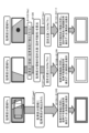
- FIG. 8 is an example of display data in which parking availability identification graphic data (color frame) generated by the process of the present disclosure is superimposed on display data (bird's-eye view) generated by synthesizing a plurality of images.
- the parking availability identification graphic data (color frame) are of the following three types. (1) Parking area identification display data (green frame) 101 (2) Display data for identification of no-parking area (red frame) 102 (3) Display data (yellow frame) 103 for identification of possible empty area Note that the colors green, red, and yellow are examples, and combinations of colors different from these may be used.
- steps S106 to S111 is executed when it is determined in step S103 that no parked vehicle has been detected in the processing target area (Px).
- FIG. 15 a specific example of the processing of steps S108 and S109 executed when the vacancy likelihood (possibility of vacancy) of the processing target area calculated in step S106 is the threshold value (Th) or more, ie, 50% or more, is shown in FIG. 15, with reference to FIG.
- the parking area P5 shown in FIG. 15 is the same upper right parking area as the parking area P5 described above with reference to FIG.
- the area that can be confirmed from the camera 11 of the vehicle 10 is increasing.
- the parking area analysis unit 151 further executes a process of acquiring parameters used for displaying the parking permission/prohibition identification graphic data (color frame).
- a parameter is a parameter containing the following data. (a) a parking segment area ID; (b) Parking availability identification result (parking allowed, parking not allowed, vacancy possible), (c) center position coordinates (x, y) of the parking section area; (d) the shape of the parking segment area (d, w); (e) the inclination angle ( ⁇ ) of the parking segment area;
- FIG. 22 does not show "(3) possible empty area identification display data (yellow frame) 103".
- the display conditions for the parking permission/inhibition identification graphic data (color frame) of (1) to (3) are as follows.
- step S207 the data processing unit of the information processing device determines the length of the vacant area (interval between parked vehicles before and after the vacant area) from each of the vacant areas for which the vacant area identifier (vacant area ID) is set. A vacant area less than a threshold (vehicle parking available length) is selected, and the selected area is determined to be a non-parking area.
- a threshold vehicle parking available length
- the length of the vacant area is equal to or greater than the threshold value (length of vehicle parking). Determine the empty area as the "processing target area”.
- the parking area analysis unit 151 further executes a process of acquiring parameters used for displaying the parking permission/prohibition identification graphic data (color frame).
- a parameter is a parameter containing the following data. (a) free space ID, (b) Parking availability identification result (parking allowed, parking not allowed, vacancy possible), (c) center position coordinates (x, y) of empty area, (d) the shape of the free space (d, w); (e) Inclination angle ( ⁇ ) of empty area,
- the parking permission/inhibition identification graphic data generation unit 152 generates parking permission/inhibition identification graphic data (color frame) using the parameters (a) to (e). Furthermore, the parking availability identification graphic data generation unit 152 superimposes the generated parking availability identification graphic data (color frame) on each area of the attention area (ROI) selected as the parking available area displayed on the display unit 153. displayed.
- ROI attention area
- the vehicle 10 is running, and the photographing range of the camera 11 mounted on the vehicle 10 is changed at any time. It is in a state of being updated sequentially.
- Step S303 On the other hand, in step S301, when no parked vehicle is detected in the "display data (yellow frame) display area for identifying an area with the possibility of being vacant", the data processing unit of the information processing device executes the process of step S303.
- Step S401 First, in step S401, the data processing unit (automatic driving control unit) of the information processing device mounted on the vehicle 10 identifies the parking possible area from the parking possibility identification graphic data (color frame) displayed on the display unit. Search the display area for the display data for use (green frame) or the display data for identifying a potentially empty area (yellow frame).
- Step S404 On the other hand, the process of step S404 is performed when the display area of the display data for identifying the parking area (green frame) is not detected from the parking possibility identification graphic data (color frame) displayed on the display unit in step S402. run to
- Step S405 In the process of step S405, it is determined that the display area of the display data for area identification (yellow frame) with the possibility of vacancy has been detected from the parking permission/prohibition identification graphic data (color frame) displayed on the display unit in step S404. Execute if
- the area analysis unit 211 of the parking area analysis unit 203 executes analysis processing of the parking area. For example, in the case of a parking lot where parking divisions are clearly defined by white lines, such as the parallel parking lot described above with reference to FIG. do. again.
- the parking area is set as a region of interest (ROI), and from the area of interest, Perform processing such as detecting empty space.
- ROI region of interest
- the area analysis unit 211 of the parking area analysis unit 203 further performs the processing of step S101 in the flowchart shown in FIG.
- the process of step S201 of the flowchart is executed.
- the vacancy likelihood (vacancy possibility) calculation unit 213 performs vacancy likelihood (vacancy possibility) calculation processing for an area in which no parked vehicle is detected.
- the vacancy likelihood (possibility of vacancy) of each area is calculated according to (Formula 1) below.
- Likelihood of vacancy (possibility of vacancy) (%) (1-(Occlusion area area)/(Parking area total area)) ⁇ 100 (%) (Formula 1)
- the occlusion area is an area that cannot be confirmed in the captured image of the camera.
- the user determines whether each area is a parking area based on the color of the parking availability identification graphic data (color frame) displayed superimposed on each area of the attention area (ROI). It is possible to immediately determine whether it is an area where parking is not possible or an area where there is a possibility of vacancy.
- FIG. 37 is an example hardware configuration of the information processing device in the vehicle 10 .
- the hardware configuration shown in FIG. 37 will be described.
- a drive 310 connected to the input/output interface 305 drives a removable medium 311 such as a magnetic disk, an optical disk, a magneto-optical disk, or a semiconductor memory such as a memory card to record or read data.
- a removable medium 311 such as a magnetic disk, an optical disk, a magneto-optical disk, or a semiconductor memory such as a memory card to record or read data.
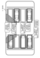
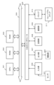
- the vehicle control system 511 includes a vehicle control ECU (Electronic Control Unit) 521, a communication unit 522, a map information accumulation unit 523, a GNSS (Global Navigation Satellite System) reception unit 524, an external recognition sensor 525, an in-vehicle sensor 526, a vehicle sensor 527, It has a recording unit 528 , a driving support/automatic driving control unit 529 , a DMS (Driver Monitoring System) 530 , an HMI (Human Machine Interface) 531 , and a vehicle control unit 532 .
- a vehicle control ECU Electronic Control Unit
- a communication unit 522 includes a communication unit 522, a map information accumulation unit 523, a GNSS (Global Navigation Satellite System) reception unit 524, an external recognition sensor 525, an in-vehicle sensor 526, a vehicle sensor 527, It has a recording unit 528 , a driving support/automatic driving control unit 529 , a DMS (Driver Monitoring System) 530
- the self-position estimator 571 may estimate the self-position of the vehicle 500 based on the GNSS signal and sensor data from the vehicle sensor 527.
- the recognition unit 573 executes a detection process for detecting the situation outside the vehicle 500 and a recognition process for recognizing the situation outside the vehicle 500 .
- trajectory planning is the process of planning a rough route from the start to the goal. This route planning is referred to as trajectory planning, and in the route planned in the route planning, trajectory generation (Local path planning) processing is also included. Path planning may be distinguished from long-term path planning and activation generation from short-term path planning, or from local path planning. A safety priority path represents a concept similar to launch generation, short-term path planning, or local path planning.
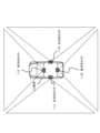
- FIG. 39 is a diagram showing an example of sensing areas by the camera 551, radar 552, LiDAR 553, ultrasonic sensor 554, etc. of the external recognition sensor 525 in FIG. 39 schematically shows the vehicle 500 viewed from above, the left end side being the front end (front) side of the vehicle 500, and the right end side being the rear end (rear) side of the vehicle 500.
- the sensing results in the sensing area 595 are used, for example, for ACC (Adaptive Cruise Control), emergency braking, and collision avoidance.
- ACC Adaptive Cruise Control
- emergency braking emergency braking
- collision avoidance collision avoidance
- the sensing regions of the camera 551, the radar 552, the LiDAR 553, and the ultrasonic sensor 554 included in the external recognition sensor 525 may have various configurations other than those shown in FIG. Specifically, the ultrasonic sensor 554 may sense the sides of the vehicle 500 , and the LiDAR 553 may sense the rear of the vehicle 500 . Moreover, the installation position of each sensor is not limited to each example mentioned above. Also, the number of each sensor may be one or plural.
Landscapes
- Physics & Mathematics (AREA)
- General Physics & Mathematics (AREA)
- Engineering & Computer Science (AREA)
- Mechanical Engineering (AREA)
- Traffic Control Systems (AREA)
Abstract
The present invention is such that, in accordance with the proportion of occlusion regions in parking sectioned regions, it is determined whether a region is either a parkable region or a possibly vacant region, and different identification display processes are performed in accordance with the identification result. The present invention includes: a parking region analysis unit that analyzes a camera captured image so as to analyze, in units of the sectioned regions, whether a vehicle can park; and a display control unit that generates parkable identification graphic data in units of the sectioned regions on the basis of the analysis result, and displays the data on the camera captured image in a superimposed manner. For sectioned regions where a parked vehicle is not detected from the camera captured image, the parking region analysis unit calculates a proportion of the occlusion regions relative to the entire area of the sectioned regions, and determines whether the sectioned regions are parkable regions or possibly vacant regions in accordance with the value of the calculated proportion, and the display control unit displays different graphic data in each region in a superimposed manner.
Description
本開示は、情報処理装置、および情報処理方法、並びにプログラムに関する。具体的には、例えば駐車場において車両の駐車可能領域を車両運転者であるユーザに分かりやすく提示する表示データを生成する情報処理装置、および情報処理方法、並びにプログラムに関する。
The present disclosure relates to an information processing device, an information processing method, and a program. More specifically, the present invention relates to an information processing device, an information processing method, and a program that generate display data for presenting a parking area for a vehicle in a parking lot in an easy-to-understand manner to a user who is a vehicle driver.
例えば、ショッピングセンターや遊園地、観光地、その他、街中等の駐車場の多くは、多数の車両を駐車可能としている場合が多い。
車両の運転者であるユーザは、駐車場から駐車可能な空きスペースを探して駐車する。この場合、ユーザは、駐車場内で車両を走行させ、周囲を目視で確認して空きスペースを探すことになる。 For example, many parking lots in shopping centers, amusement parks, sightseeing spots, and other places in cities can park a large number of vehicles.
A user who is a driver of a vehicle searches for an available parking space in the parking lot and parks the vehicle. In this case, the user runs the vehicle in the parking lot and visually checks the surroundings to search for an empty space.
このような駐車可能スペースの確認処理は時間を要し、また、狭い駐車場内で走行を行うと他の車両や人との接触事故が起こりやすいという問題がある。
The process of confirming parking spaces like this takes time, and there is the problem that when driving in a narrow parking lot, collisions with other vehicles or people are likely to occur.
駐車場において駐車可能領域の検出を行う構成を開示した従来技術として、例えば特許文献1(国際公開WO2017/068701号公報)がある。
For example, Patent Document 1 (International Publication No. WO2017/068701) discloses a conventional technology that discloses a configuration for detecting a parking area in a parking lot.
この特許文献1は、並列駐車型の駐車場において、車両に搭載されたカメラを用いて駐車可否の判別対象とする駐車区分領域の隣の駐車車両を撮影し、隣の駐車車両の側面部が撮影画像内にしきい値以上の長さで撮影されていれば、駐車可否判別対象領域が空きスペースであると判定する構成を開示している。
In this patent document 1, in a parallel parking type parking lot, a camera mounted on a vehicle is used to photograph a parked vehicle next to a parking division area to be determined whether parking is possible, and the side part of the next parked vehicle is photographed. A configuration is disclosed in which it is determined that a parking availability determination target area is an empty space if the captured image has a length equal to or greater than a threshold value.
しかし、この開示手法は、並列駐車型の駐車場であること、駐車可否判別区分領域の隣に駐車車両が存在していること、これらの条件が満たされていることが必須要件である。従って、例えば明確な駐車区分領域が規定されていない駐車場や、縦列駐車領域などには適用できず、利用可能な条件が極めて限定されてしまうという問題がある。
However, for this disclosure method, it is essential that the parking lot is a parallel parking type, that a parked vehicle exists next to the partitioned area for determining whether parking is possible, and that these conditions are met. Therefore, there is a problem that the available conditions are extremely limited because it cannot be applied to, for example, a parking lot in which a clear parking zone is not specified or a parallel parking zone.
本開示は、例えば上記問題点に鑑みてなされたものであり、並列駐車、縦列駐車など様々な駐車場のタイプに適用可能であり、さらに駐車可否のみならず空き可能性情報も含めて車両運転者であるユーザに提示することを可能とした情報処理装置、および情報処理方法、並びにプログラムを提供することを目的とする。
The present disclosure has been made in view of the above problems, for example, and is applicable to various types of parking lots such as parallel parking and parallel parking. It is an object of the present invention to provide an information processing device, an information processing method, and a program that can be presented to a user who is a person.
本開示の第1の側面は、
車両に装着したカメラの撮影画像を解析して、車両が駐車可能か否かを区分領域単位で解析する駐車領域解析部と、
前記駐車領域解析部の解析結果に基づいて、区分領域単位の駐車可否識別グラフィックデータを生成し、前記カメラの撮影画像、または撮影画像に基づいて生成した合成画像上に重畳して表示する表示制御部を有し、
前記駐車領域解析部は、
前記カメラの撮影画像から駐車車両が検出されない区分領域について、前記カメラの撮影画像から確認できないオクルージョン領域の区分領域全面積に対する比率を算出し、
算出比率の値に応じて区分領域が、駐車可能領域、または空き可能性あり領域のいずれの領域であるかを判定する判定処理を実行し、
前記表示制御部は、
前記判定処理の結果に応じて、駐車可能領域と空き可能性あり領域とで異なるグラフィックデータを重畳して表示する情報処理装置にある。 A first aspect of the present disclosure includes:
a parking area analysis unit that analyzes an image captured by a camera mounted on the vehicle and analyzes whether the vehicle can be parked in units of divided areas;
Display control for generating parking availability identification graphic data for each segment based on the analysis result of the parking area analysis unit and superimposing it on the image captured by the camera or a composite image generated based on the captured image. has a part
The parking area analysis unit
calculating the ratio of the occlusion area that cannot be confirmed from the image captured by the camera to the total area of the segmented area for the segmented area in which the parked vehicle is not detected from the image captured by the camera;
Execute a determination process for determining whether the divided area is a parking available area or an area with the possibility of vacancy according to the value of the calculation ratio,
The display control unit
In the information processing device, different graphic data are superimposed and displayed for the parking available area and the possible vacant area according to the result of the determination process.
さらに、本開示の第2の側面は、
情報処理装置において実行する情報処理方法であり、
駐車領域解析部が、
車両に装着したカメラの撮影画像を解析して、車両が駐車可能か否かを区分領域単位で解析する駐車領域解析ステップと、
表示制御部が、
前記駐車領域解析部の解析結果に基づいて、区分領域単位の駐車可否識別グラフィックデータを生成し、前記カメラの撮影画像、または該撮影画像に基づいて生成した合成画像上に重畳して表示する表示制御ステップを実行し、
前記駐車領域解析部は、前記駐車領域解析ステップにおいて、
前記カメラの撮影画像から駐車車両が検出されない区分領域について、前記カメラの撮影画像から確認できないオクルージョン領域の区分領域全面積に対する比率を算出し、
算出比率の値に応じて区分領域が、駐車可能領域、または空き可能性あり領域のいずれの領域であるかを判定する判定処理を実行し、
前記表示制御部は、前記表示制御ステップにおいて、
前記判定処理の結果に応じて、駐車可能領域と空き可能性あり領域とで異なるグラフィックデータを重畳して表示する情報処理方法にある。 Furthermore, a second aspect of the present disclosure is
An information processing method executed in an information processing device,
The parking area analysis unit
a parking area analysis step of analyzing an image captured by a camera mounted on the vehicle and analyzing whether or not the vehicle can be parked in units of divided areas;
The display control unit
Based on the analysis result of the parking area analysis unit, parking availability identification graphic data is generated for each segmented area, and displayed superimposed on the image captured by the camera or a composite image generated based on the captured image. perform a control step,
The parking area analysis unit, in the parking area analysis step,
calculating the ratio of the occlusion area that cannot be confirmed from the image captured by the camera to the total area of the segmented area for the segmented area in which the parked vehicle is not detected from the image captured by the camera;
Execute a determination process for determining whether the divided area is a parking available area or an area with the possibility of vacancy according to the value of the calculation ratio,
The display control unit, in the display control step,
In the information processing method, different graphic data are superimposed and displayed for the parking available area and the possible vacant area according to the result of the determination process.
さらに、本開示の第3の側面は、
情報処理装置において情報処理を実行させるプログラムであり、
駐車領域解析部に、
車両に装着したカメラの撮影画像を解析して、車両が駐車可能か否かを区分領域単位で解析する駐車領域解析ステップを実行させ、
表示制御部に、
前記駐車領域解析部の解析結果に基づいて、区分領域単位の駐車可否識別グラフィックデータを生成し、前記カメラの撮影画像、または該撮影画像に基づいて生成した合成画像上に重畳して表示する表示制御ステップを実行させ、
前記駐車領域解析部の前記駐車領域解析ステップにおいて、
前記カメラの撮影画像から駐車車両が検出されない区分領域について、前記カメラの撮影画像から確認できないオクルージョン領域の区分領域全面積に対する比率を算出する処理と、
算出比率の値に応じて区分領域が、駐車可能領域、または空き可能性あり領域のいずれの領域であるかを判定する判定処理を実行させ、
前記表示制御部の前記表示制御ステップにおいて、
前記判定処理の結果に応じて、駐車可能領域と空き可能性あり領域とで異なるグラフィックデータを重畳して表示する処理を実行させるプログラムにある。 Furthermore, a third aspect of the present disclosure is
A program for executing information processing in an information processing device,
In the parking area analysis part,
executing a parking area analysis step of analyzing an image captured by a camera mounted on the vehicle and analyzing whether or not the vehicle can be parked in units of divided areas;
In the display control section,
Based on the analysis result of the parking area analysis unit, parking availability identification graphic data is generated for each segmented area, and displayed superimposed on the image captured by the camera or a composite image generated based on the captured image. let the control step run,
In the parking area analysis step of the parking area analysis unit,
A process of calculating a ratio of an occlusion area that cannot be confirmed from the image captured by the camera to the total area of the segmented area, for the segmented area in which the parked vehicle is not detected from the image captured by the camera;
Determination processing is performed to determine whether the divided area is a parking available area or an area with the possibility of vacancy according to the value of the calculation ratio,
In the display control step of the display control unit,
The program causes execution of a process of superimposing and displaying different graphic data for the parking available area and the potentially vacant area according to the result of the determination process.
なお、本開示のプログラムは、例えば、様々なプログラム・コードを実行可能な情報処理装置、画像処理装置やコンピュータ・システムに対して、コンピュータ可読な形式で提供する記憶媒体、通信媒体によって提供可能なプログラムである。このようなプログラムをコンピュータ可読な形式で提供することにより、情報処理装置やコンピュータ・システム上でプログラムに応じた処理が実現される。
Note that the program of the present disclosure can be provided, for example, in a computer-readable format to an information processing device, an image processing device, or a computer system capable of executing various program codes via a storage medium or a communication medium. It's a program. By providing such a program in a computer-readable format, processing according to the program is realized on the information processing device or computer system.
本開示のさらに他の目的、特徴や利点は、後述する本発明の実施例や添付する図面に基づくより詳細な説明によって明らかになるであろう。なお、本明細書においてシステムとは、複数の装置の論理的集合構成であり、各構成の装置が同一筐体内にあるものには限らない。
Further objects, features, and advantages of the present disclosure will become apparent from the detailed description based on the embodiments of the present invention and the accompanying drawings, which will be described later. In this specification, a system is a logical collective configuration of a plurality of devices, and the devices of each configuration are not limited to being in the same housing.
本開示の一実施例の構成によれば、駐車区分領域のオクルージョン領域の比率に応じて、駐車可能領域、または空き可能性あり領域のいずれであるかを判別して、判別結果に応じて異なる識別表示処理を行う構成が実現される。
具体的には、例えば、カメラ撮影画像を解析して、車両が駐車可能か否かを区分領域単位で解析する駐車領域解析部と、解析結果に基づいて区分領域単位の駐車可否識別グラフィックデータを生成し、カメラ撮影画像上に重畳表示する表示制御部を有する。駐車領域解析部は、カメラ撮影画像から駐車車両が検出されない区分領域について、オクルージョン領域の区分領域全面積に対する比率を算出し、算出比率の値に応じて区分領域が駐車可能領域、または空き可能性あり領域のいずれであるかを判定し、表示制御部は、各領域で異なるグラフィックデータを重畳して表示する。
本構成により、駐車区分領域のオクルージョン領域の比率に応じて、駐車可能領域、または空き可能性あり領域のいずれであるかを判別して、判別結果に応じて異なる識別表示処理を行う構成が実現される。
なお、本明細書に記載された効果はあくまで例示であって限定されるものではなく、また付加的な効果があってもよい。 According to the configuration of one embodiment of the present disclosure, depending on the ratio of the occlusion area of the parking division area, it is determined whether it is a parking available area or an area with the possibility of being vacant, and different depending on the determination result A configuration for performing identification display processing is realized.
Specifically, for example, a parking area analysis unit that analyzes images captured by a camera and analyzes whether or not the vehicle can be parked in units of partitioned areas, and based on the analysis results, stores parking availability identification graphic data in units of partitioned areas. It has a display control unit that generates and displays superimposed on the image captured by the camera. The parking area analysis unit calculates the ratio of the occlusion area to the total area of the divided area for the divided area where no parked vehicle is detected from the image captured by the camera. The display control unit determines which of the existing areas is, and superimposes and displays different graphic data in each area.
With this configuration, it is possible to determine whether the area is a parking area or an area with the possibility of being vacant according to the ratio of the occlusion area of the parking area, and perform different identification display processing according to the determination result. be done.
Note that the effects described in this specification are merely examples and are not limited, and additional effects may be provided.
以下、図面を参照しながら本開示の情報処理装置、および情報処理方法、並びにプログラムの詳細について説明する。なお、説明は以下の項目に従って行う。
1.駐車場における車両駐車処理の一般的な処理と、その問題点について
2.駐車可能領域と駐車不可領域、さらに空き可能性あり領域の3種類の領域識別用データを生成してユーザに提示する本開示の処理について
3.(実施例1)本開示の情報処理装置が実行する処理の詳細について
4.(実施例2)駐車区分領域が規定されていない縦列駐車の場合の処理例について
5.表示データの更新処理について
6.車両が自動運転車両である場合の自動運転処理について
7.本開示の情報処理装置の構成例について
8.本開示の情報処理装置のハードウェア構成例について
9.車両の構成例について
10.本開示の構成のまとめ Details of the information processing apparatus, the information processing method, and the program according to the present disclosure will be described below with reference to the drawings. In addition, explanation is given according to the following items.
1. General processing of vehicle parking processing in a parking lot and itsproblems 2. 3. Regarding the processing of the present disclosure for generating and presenting to the user three types of data for area identification, that is, a parking area, a non-parking area, and an area with the possibility of being vacant. (Embodiment 1) Details of processing executed by the information processing apparatus of the present disclosure4. (Embodiment 2) Regarding a processing example in the case of parallel parking in which the parking area is not specified5. Regarding update processing of display data6. Regarding automatic driving processing when the vehicle is an automatic driving vehicle7. Configuration example of information processing apparatus of the present disclosure8. Hardware Configuration Example of Information Processing Apparatus of Present Disclosure9. 10. Configuration example of vehicle; SUMMARY OF THE STRUCTURE OF THE DISCLOSURE
1.駐車場における車両駐車処理の一般的な処理と、その問題点について
2.駐車可能領域と駐車不可領域、さらに空き可能性あり領域の3種類の領域識別用データを生成してユーザに提示する本開示の処理について
3.(実施例1)本開示の情報処理装置が実行する処理の詳細について
4.(実施例2)駐車区分領域が規定されていない縦列駐車の場合の処理例について
5.表示データの更新処理について
6.車両が自動運転車両である場合の自動運転処理について
7.本開示の情報処理装置の構成例について
8.本開示の情報処理装置のハードウェア構成例について
9.車両の構成例について
10.本開示の構成のまとめ Details of the information processing apparatus, the information processing method, and the program according to the present disclosure will be described below with reference to the drawings. In addition, explanation is given according to the following items.
1. General processing of vehicle parking processing in a parking lot and its
[1.駐車場における車両駐車処理の一般的な処理と、その問題点について]
まず、駐車場における車両駐車処理の一般的な処理と、その問題点について説明する。 [1. General processing of vehicle parking processing in parking lots and its problems]
First, general processing of vehicle parking processing in a parking lot and its problems will be described.
まず、駐車場における車両駐車処理の一般的な処理と、その問題点について説明する。 [1. General processing of vehicle parking processing in parking lots and its problems]
First, general processing of vehicle parking processing in a parking lot and its problems will be described.
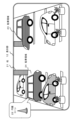
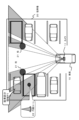
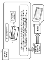
図1以下を参照して、車両を駐車場に駐車させる場合の一般的な車両走行例について説明する。
図1には、車両10と駐車場20を示している、車両10は、駐車場20の入り口から駐車場20に入り、空きスペースを探して駐車しようとしている。 With reference to FIG. 1 and subsequent drawings, a general example of vehicle travel when the vehicle is parked in a parking lot will be described.
FIG. 1 shows a vehicle 10 and a parking lot 20. The vehicle 10 enters the parking lot 20 from the entrance of the parking lot 20 and seeks an empty space to park.
図1の状態で、車両10の運転者であるユーザは、車両前方を見ながら、駐車場20の入り口から駐車場内に侵入する。
例えば、店舗の入り口が、駐車場の奥側(図の上方側)にあるため、車両10の運転者であるユーザは、できるだけ駐車場の奥側(図の上方側)に駐車したいと考えているとする。 In the state of FIG. 1, the user who is the driver of the vehicle 10 enters the parking lot from the entrance of the parking lot 20 while looking ahead of the vehicle.
For example, since the entrance of the store is on the back side of the parking lot (upper side in the figure), the user who is the driver of the vehicle 10 wants to park as far back as possible in the parking lot (upper side in the figure). Suppose there is
しかし、駐車場にすでに駐車している駐車車両や柱21などによって運転者の視界が遮られるため、侵入時点では、駐車区分領域のどこが空いているかを判断することは困難である。
また、図に示す駐車区分の左上端から2番目の駐車領域は空いてはいるが、円錐コーン22がおかれているため利用できない領域となっている。
しかし、侵入時点では車両10の運転者であるユーザは、この円錐コーン22を視覚で確認することができない。 However, since the driver's field of vision is blocked by the vehicles already parked in the parking lot, the pillars 21, etc., it is difficult to determine which parking zone is vacant at the time of entry.
In addition, although the second parking area from the upper left corner of the parking section shown in the figure is vacant, it is an area that cannot be used because the conical cone 22 is placed thereon.
However, the user, who is the driver of the vehicle 10, cannot visually confirm the cone 22 at the time of entry.
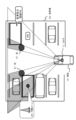
なお、図2に示すように、車両10がカメラ11を備えた車両である場合、カメラ11によって撮影された画像が車両10内の表示部12に表示される。運転者であるユーザは、この表示データを見て、駐車場の全体を観察することができる。
As shown in FIG. 2, when the vehicle 10 is equipped with a camera 11, an image captured by the camera 11 is displayed on the display unit 12 inside the vehicle 10. A user who is a driver can observe the entire parking lot by looking at this display data.
表示部12に表示される撮影画像の例を図3に示す。
表示部12には、例えば図3に示すようなカメラ撮影画像が表示される。しかし、この表示画像を見ても、例えば、駐車場の右奥の駐車領域23は、手前の駐車車両の陰になっており、運転者は駐車可能か否かを明確に判定することができない。 An example of a captured image displayed on the display unit 12 is shown in FIG.
The display unit 12 displays an image captured by a camera, for example, as shown in FIG. However, even looking at this display image, for example, the parking area 23 at the far right of the parking lot is in the shadow of the parked vehicle in front, and the driver cannot clearly determine whether or not parking is possible. .
また、駐車場左側の奥から2番目の駐車領域24も手前の駐車車両の陰になっており、運転者は駐車可能か否かを明確に判定することができない。この駐車領域24には、円錐コーン22がおかれているが、カメラ11の撮影画像には撮影されていないため運転者は円錐コーン22の存在も全く確認できない。
In addition, the second parking area 24 from the back on the left side of the parking lot is also behind the parked vehicles in front, and the driver cannot clearly determine whether or not parking is possible. Although the conical cone 22 is placed in the parking area 24, the driver cannot confirm the presence of the conical cone 22 at all because it is not photographed in the photographed image of the camera 11.例文帳に追加
[2.駐車可能領域と駐車不可領域、さらに空き可能性あり領域の3種類の領域識別用データを生成してユーザに提示する本開示の処理について]
次に、駐車可能領域と駐車不可領域、さらに空き可能性あり領域の3種類の領域識別用データを生成してユーザに提示する本開示の処理について説明する。 [2. Regarding the processing of the present disclosure that generates and presents to the user three types of area identification data, a parking available area, a parking non-parking area, and an area with the possibility of vacancy]
Next, a description will be given of the process of the present disclosure for generating three types of area identification data, ie, a parking area, a non-parking area, and a possibly empty area, and presenting them to the user.
図4は、本開示の処理によって車両10の表示部12に表示される表示データの例を示す図である。
FIG. 4 is a diagram showing an example of display data displayed on the display unit 12 of the vehicle 10 by the process of the present disclosure.
図4に示す表示データは、先に図3を参照して説明したカメラ11の撮影画像内の駐車区分領域各々に3種類の駐車可否識別グラフィックデータ(カラー枠)のいずれかを重畳して表示した表示データである。
The display data shown in FIG. 4 is displayed by superimposing one of three types of parking permission/inhibition identification graphic data (color frame) on each of the parking classification areas in the captured image of the camera 11 described above with reference to FIG. This is the displayed data.
重畳表示する駐車可否識別グラフィックデータ(カラー枠)は、以下の3種類である。
(1)駐車可能領域識別用表示データ(緑色枠)101
(2)駐車不可領域識別用表示データ(赤色枠)102
(3)空き可能性あり領域識別用表示データ(黄色枠)103
なお、緑、赤、黄の色は一例であり、これらと異なる色の組み合わせでもよい。 The following three types of parking availability identification graphic data (color frame) are superimposed and displayed.
(1) Parking area identification display data (green frame) 101
(2) Display data for identification of no-parking area (red frame) 102
(3) Display data (yellow frame) 103 for identification of possible empty areas
Note that the colors green, red, and yellow are examples, and combinations of colors different from these may be used.
「(1)駐車可能領域識別用表示データ(緑色枠)101」は、車両10に装着されたカメラ11による撮影画像の解析結果として駐車車両が検出されず、かつ、空き尤度(空き可能性)が規定しきい値以上の駐車区分領域に対して重畳表示される。
"(1) Parking area identification display data (green frame) 101" indicates that no parked vehicle is detected as an analysis result of the image captured by the camera 11 attached to the vehicle 10, and the likelihood of vacancy (possibility of vacancy ) is displayed superimposed on the parking zone area equal to or larger than the specified threshold.
「(2)駐車不可領域識別用表示データ(赤色枠)102」は、車両10に装着されたカメラ11による撮影画像の解析結果として駐車車両が検出された駐車区分領域に対して重畳表示される。
"(2) Parking prohibited area identification display data (red frame) 102" is superimposed on the parking area where the parked vehicle is detected as the analysis result of the image captured by the camera 11 mounted on the vehicle 10. .
「(3)空き可能性あり領域識別用表示データ(黄色枠)103」は、車両10に装着されたカメラ11による撮影画像の解析結果として駐車車両が検出されず、かつ、空き尤度(空き可能性)が規定しきい値未満の駐車区分領域に対して重畳表示される。
"(3) Display data for identification of area with possibility of vacancy (yellow frame) 103" indicates that no parked vehicle is detected as an analysis result of the image captured by the camera 11 attached to the vehicle 10, and the likelihood of vacancy (vacancy possibility) is superimposed on the parking segment areas below the specified threshold.
空き尤度(空き可能性)とは、駐車区分領域が空いており、駐車可能である可能性を示す指標値である。この空き尤度(空き可能性)の算出処理の詳細については後段で説明する。
The vacancy likelihood (vacancy possibility) is an index value that indicates the possibility that the parking area is vacant and parking is possible. The details of this vacancy likelihood (vacancy possibility) calculation processing will be described later.
なお、図4に示す図は、図面上では白黒画として示しているが、車両10の表示部12に表示される画像はカラー画像であり、領域識別用表示データ(緑色枠、赤色枠、黄色枠)は、高輝度のカラーデータとして表示されるため、ユーザ(運転者)は、即座に各駐車領域の3状態(駐車可能、駐車不可能、空き可能性あり)を判別することができる。
Although the diagram shown in FIG. 4 is shown as a black and white image on the drawing, the image displayed on the display unit 12 of the vehicle 10 is a color image, and the area identification display data (green frame, red frame, yellow frame). The frame) is displayed as high-brightness color data, so the user (driver) can immediately determine the three states of each parking area (parkable, unparkable, and possibly vacant).
図4に示す図は白黒画で分かりにくいため、背景の車両を省略したデータ例を図5に示す。
図5に示すように、駐車区分領域の各々に対して、以下の3種類の駐車可否識別グラフィックデータ(カラー枠)が表示される。
(1)駐車可能領域識別用表示データ(緑色枠)101
(2)駐車不可領域識別用表示データ(赤色枠)102
(3)空き可能性あり領域識別用表示データ(黄色枠)103 Since the diagram shown in FIG. 4 is a black-and-white image, it is difficult to understand, so FIG. 5 shows an example of data in which background vehicles are omitted.
As shown in FIG. 5, the following three types of parking availability identification graphic data (color frame) are displayed for each parking area.
(1) Parking area identification display data (green frame) 101
(2) Display data for identification of no-parking area (red frame) 102
(3) Display data (yellow frame) 103 for identification of possible empty areas
ユーザ(運転者)は、駐車区分領域の各々に重畳されて表示される駐車可否識別グラフィックデータ(カラー枠)の色に基づいて、各駐車領域が駐車可能な領域であるか、駐車不可能な領域であるか、空き可能性ありの領域であるかを、即座に判別することができる。
The user (driver) can determine whether each parking area is a parking area or not based on the color of the parking permission/prohibition identification graphic data (color frame) superimposed on each parking area. It is possible to immediately determine whether the area is an area or an area with the possibility of being free.
なお、図4、図5に示す例は、表示部12に表示する表示データとして、図2に示す車両10の前方を撮影するカメラ11によって撮影した画像を利用した例である。
表示部12に表示する表示データは、このような前方撮影カメラによる撮影画像に限らず、様々なデータとすることが可能である。 Note that the examples shown in FIGS. 4 and 5 are examples in which an image captured by the camera 11 that captures the front of the vehicle 10 shown in FIG. 2 is used as the display data displayed on the display unit 12 .
The display data to be displayed on the display unit 12 is not limited to the image captured by the front camera, and may be various data.
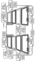
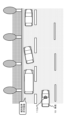
例えば、図6に示すように、車両10に前後左右を撮影する複数のカメラを搭載し、これらのカメラによって撮影された画像を合成して上方から観察された画像、すなわち鳥瞰図を生成して表示してもよい。
For example, as shown in FIG. 6, a vehicle 10 is equipped with a plurality of cameras for photographing the front, rear, left, and right, and the images photographed by these cameras are synthesized to generate and display an image observed from above, that is, a bird's-eye view. You may
図6に示す車両10は、以下の4つのカメラを搭載している。
(a)車両10の前方を撮影する前方向カメラ11F、
(b)車両10の後方を撮影する後方向カメラ11B、
(c)車両10の左側を撮影する左方向カメラ11L、
(d)車両10の右側を撮影する右方向カメラ11R、 The vehicle 10 shown in FIG. 6 is equipped with the following four cameras.
(a) a front-facing camera 11F that captures the front of the vehicle 10;
(b) a rear camera 11B that captures the rear of the vehicle 10;
(c) a left direction camera 11L that captures the left side of the vehicle 10;
(d) a right direction camera 11R that captures the right side of the vehicle 10;
これら車両10の前後左右4方向の画像を撮影するカメラの撮影画像を合成することで、車両10の上方から観察される画像、すなわち鳥瞰図を生成することが可能となる。
このような処理によって車両10の表示部12に表示される画像の例を図7に示す。 By synthesizing the captured images of the vehicle 10 in four directions, it is possible to generate an image observed from above the vehicle 10, that is, a bird's-eye view.
FIG. 7 shows an example of an image displayed on the display unit 12 of the vehicle 10 through such processing.
図7に示す表示データは、図6を参照して説明した車両10の前後左右4方向の画像を撮影するカメラ11F,11L,11B,11Rの4つの撮影画像を合成して生成された鳥瞰図によって構成される表示データの例である。
The display data shown in FIG. 7 is a bird's-eye view generated by synthesizing four captured images of the vehicle 10, which are captured by the cameras 11F, 11L, 11B, and 11R in the four directions of the vehicle 10 described with reference to FIG. 4 is an example of constructed display data.
なお、柱21は歪んで見えているが、これは複数画像の合成処理よって発生する歪である。また、本来、存在するはずの円錐コーン22は表示されていない。この円錐コーン22は、例えば手前の駐車領域に駐車された車両の陰になり、4つのカメラのいずれにも撮影されていないからである。
このように、複数画像の合成処理よって生成される表示データ(鳥瞰図)は、被写体の歪みなどが発生し、運転者(ユーザ)が、即座に各駐車領域の状態(駐車可能、駐車不可能、空き可能性あり)を判別することは困難である。 Note that the pillar 21 appears distorted, but this is distortion generated by the process of synthesizing a plurality of images. Also, the conical cone 22 that should exist is not displayed. This is because the conical cone 22 is, for example, behind the vehicles parked in the front parking area and is not captured by any of the four cameras.
In this way, the display data (bird's-eye view) generated by synthesizing a plurality of images has distortion of the subject, etc., and the driver (user) can immediately see the state of each parking area (parking possible, parking not possible, etc.). (Possibly empty) is difficult to discriminate.
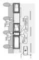
図8は、複数画像の合成処理よって生成される表示データ(鳥瞰図)に対して本開示の処理によって生成される駐車可否識別グラフィックデータ(カラー枠)を重畳した表示データの例である。
駐車可否識別グラフィックデータ(カラー枠)は、以下の3種類である。
(1)駐車可能領域識別用表示データ(緑色枠)101
(2)駐車不可領域識別用表示データ(赤色枠)102
(3)空き可能性あり領域識別用表示データ(黄色枠)103
なお、緑、赤、黄の色は一例であり、これらと異なる色の組み合わせでもよい。 FIG. 8 is an example of display data in which parking availability identification graphic data (color frame) generated by the process of the present disclosure is superimposed on display data (bird's-eye view) generated by synthesizing a plurality of images.
The parking availability identification graphic data (color frame) are of the following three types.
(1) Parking area identification display data (green frame) 101
(2) Display data for identification of no-parking area (red frame) 102
(3) Display data (yellow frame) 103 for identification of possible empty area
Note that the colors green, red, and yellow are examples, and combinations of colors different from these may be used.
(1)~(3)の駐車可否識別グラフィックデータ(カラー枠)の意味は、先に図4、図5を参照して説明したと同様の意味である。
すなわち、「(1)駐車可能領域識別用表示データ(緑色枠)101」は、車両10に装着されたカメラ11による撮影画像の解析結果として駐車車両が検出されず、かつ、空き尤度(空き可能性)が規定しきい値以上の駐車区分領域に対して重畳表示される。 The meanings of the parking availability identification graphic data (color frames) of (1) to (3) are the same as those explained with reference to FIGS. 4 and 5 above.
That is, "(1) display data for identifying parking area (green frame) 101" indicates that no parking vehicle is detected as an analysis result of the image captured by the camera 11 attached to the vehicle 10, and the vacancy likelihood (vacancy possibility) is displayed superimposed on the parking zone area equal to or greater than the specified threshold.
「(2)駐車不可領域識別用表示データ(赤色枠)102」は、車両10に装着されたカメラ11による撮影画像の解析結果として駐車車両が検出された駐車区分領域に対して重畳表示される。
「(3)空き可能性あり領域識別用表示データ(黄色枠)103」は、車両10に装着されたカメラ11による撮影画像の解析結果として駐車車両が検出されず、かつ、空き尤度(空き可能性)が規定しきい値未満の駐車区分領域に対して重畳表示される。 "(2) Parking prohibited area identification display data (red frame) 102" is superimposed on the parking area where the parked vehicle is detected as the analysis result of the image captured by the camera 11 mounted on the vehicle 10. .
"(3) Display data for identification of area with possibility of vacancy (yellow frame) 103" indicates that no parked vehicle is detected as an analysis result of the image captured by the camera 11 attached to the vehicle 10, and the likelihood of vacancy (vacancy possibility) is superimposed on the parking segment areas below the specified threshold.
なお、図8に示す図は、図面上では白黒画として示しているが、車両10の表示部12に表示される画像はカラー画像であり、領域識別用表示データ(緑色枠、赤色枠、黄色枠)は、高輝度のカラーデータとして表示されるため、ユーザ(運転者)は、即座に各駐車領域の3状態(駐車可能、駐車不可能、空き可能性あり)を判別することができる。背景の車両を省略したデータ例を図9に示す。
Although the diagram shown in FIG. 8 is shown as a black and white image on the drawing, the image displayed on the display unit 12 of the vehicle 10 is a color image, and the area identification display data (green frame, red frame, yellow frame). The frame) is displayed as high-brightness color data, so the user (driver) can immediately determine the three states of each parking area (parkable, unparkable, and possibly vacant). FIG. 9 shows an example of data in which background vehicles are omitted.
図9に示すように、駐車区分領域の各々に対して、以下の3種類の駐車可否識別グラフィックデータ(カラー枠)が表示される。
(1)駐車可能領域識別用表示データ(緑色枠)101
(2)駐車不可領域識別用表示データ(赤色枠)102
(3)空き可能性あり領域識別用表示データ(黄色枠)103 As shown in FIG. 9, the following three types of parking availability identification graphic data (color frame) are displayed for each parking area.
(1) Parking area identification display data (green frame) 101
(2) Display data for identification of no-parking area (red frame) 102
(3) Display data (yellow frame) 103 for identification of possible empty area
ユーザ(運転者)は、駐車区分領域の各々に重畳されて表示される駐車可否識別グラフィックデータ(カラー枠)の色に基づいて、各駐車領域が駐車可能な領域であるか、駐車不可能な領域であるか、空き可能性ありの領域であるかを、即座に判別することができる。
The user (driver) can determine whether each parking area is a parking area or not based on the color of the parking permission/prohibition identification graphic data (color frame) superimposed on each parking area. It is possible to immediately determine whether the area is an area or an area with the possibility of being free.
[3.(実施例1)本開示の情報処理装置が実行する処理の詳細について]
次に、本開示の実施例1の情報処理装置が実行する処理の詳細について説明する。 [3. (Embodiment 1) Details of processing executed by the information processing apparatus of the present disclosure]
Next, details of processing executed by the information processing apparatus according to the first embodiment of the present disclosure will be described.
なお、本開示の情報処理装置は車両10に搭載された情報処理装置である。
情報処理装置は、車両に装着されたカメラの撮影画像を入力して、表示部への表示データを生成するとともに、撮影画像の解析処理を実行して、駐車区分領域各々の駐車可否等を判別し、駐車区分領域各々に対する駐車可否識別グラフィックデータ(カラー枠)を生成して表示部に表示された駐車場画像に重畳して表示する処理などを行う。 Note that the information processing device of the present disclosure is an information processing device mounted on the vehicle 10 .
The information processing device receives an image captured by a camera mounted on the vehicle, generates display data for the display unit, and analyzes the captured image to determine whether parking is permitted in each parking area. Then, a process of generating parking permission/prohibition identification graphic data (color frame) for each parking area and superimposing it on the parking lot image displayed on the display unit is performed.
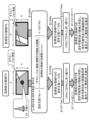
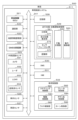
本開示の情報処理装置が実行する処理のシーケンスについて図10に示すフローチャートを参照して説明する。
なお、図10に示すフローチャートは、本開示の情報処理装置のデータ処理部の制御の下で実行される。本開示の情報処理装置は例えばCPU等のプログラム実行機能を持つデータ処理部を有し、データ処理部は情報処理装置内の記憶部に格納されたプログラムに従って図10に示すフローに従った処理を実行する。
以下、図10に示すフローチャートの各ステップの処理について説明する。 A sequence of processing executed by the information processing apparatus of the present disclosure will be described with reference to the flowchart shown in FIG.
Note that the flowchart shown in FIG. 10 is executed under the control of the data processing unit of the information processing apparatus of the present disclosure. The information processing apparatus of the present disclosure has a data processing unit having a program execution function such as a CPU, and the data processing unit performs processing according to the flow shown in FIG. 10 according to a program stored in a storage unit within the information processing apparatus. Execute.
Processing of each step of the flowchart shown in FIG. 10 will be described below.
(ステップS101)
まず、車両10に搭載された情報処理装置のデータ処理部は、ステップS101において、カメラの撮影画像等のセンサ検出情報、またはセンサ検出情報とAI予測データ、または、外部からの入力情報に基づいて、駐車区分領域を検出し、検出した駐車区分領域に駐車区分領域識別子(ID)を設定する。 (Step S101)
First, in step S101, the data processing unit of the information processing device mounted on the vehicle 10, based on sensor detection information such as an image captured by a camera, or sensor detection information and AI prediction data, or input information from the outside. , detecting a parking zone area and setting a parking zone identifier (ID) to the detected parking zone area.
カメラの撮影画像とは、例えば図2を参照して説明した車両10の前方を撮影するカメラ11の撮影画像、あるいは図6を参照して説明した以下の4つのカメラ、
(a)車両10の前方を撮影する前方向カメラ11F、
(b)車両10の後方を撮影する後方向カメラ11B、
(c)車両10の左側を撮影する左方向カメラ11L、
(d)車両10の右側を撮影する右方向カメラ11R、
これらの4つのカメラの全て、あるいは複数カメラの撮影画像、あるいはこれらの複数の撮影画像に基づいて生成される合成画像(鳥瞰図)である。 The captured image of the camera is, for example, the captured image of the camera 11 that captures the front of the vehicle 10 described with reference to FIG. 2, or the following four cameras described with reference to FIG.
(a) a front-facing camera 11F that captures the front of the vehicle 10;
(b) a rear camera 11B that captures the rear of the vehicle 10;
(c) a left direction camera 11L that captures the left side of the vehicle 10;
(d) a right direction camera 11R that captures the right side of the vehicle 10;
It is a composite image (bird's-eye view) generated based on all of these four cameras, images captured by a plurality of cameras, or a plurality of images captured by these cameras.
ステップS101では、少なくとも1つ以上のカメラ撮影画像から駐車区分領域を検出し、検出した駐車区分領域に駐車区分領域識別子(ID)を設定する。
In step S101, a parking zone area is detected from at least one camera-captured image, and a parking zone identifier (ID) is set for the detected parking zone area.
あるいは、カメラ撮影画像のみならず、AI予測データを利用して駐車区分領域を推定してもよい。
例えば、畳み込みニューラルネットワークであるCNN(Convolutional Neural Network)を用いた学習アルゴリズムによって生成されるAI予測器を利用して、カメラによって明確に撮影されない領域の駐車区分領域を判別して駐車区分領域の推定処理を行ってもよい。 Alternatively, the parking area may be estimated using not only the camera-captured image but also AI prediction data.
For example, an AI predictor generated by a learning algorithm using a convolutional neural network (CNN) is used to determine the parking area in an area that is not clearly captured by the camera and estimate the parking area. processing may be performed.
あるいは、外部からの入力情報、例えば駐車場情報提供サーバから提供される駐車場情報を用いて、駐車区分領域を検出する処理を行ってもよい。
Alternatively, the processing for detecting the parking zone area may be performed using input information from the outside, such as parking lot information provided by a parking lot information providing server.
このように、ステップS101では、カメラの撮影画像等のセンサ検出情報、またはセンサ検出情報とAI予測データ、または、外部からの入力情報に基づいて、駐車区分領域を検出し、検出した駐車区分領域に駐車区分領域識別子(ID)を設定する。
Thus, in step S101, based on sensor detection information such as a photographed image of a camera, sensor detection information and AI prediction data, or input information from the outside, the parking area is detected, and the detected parking area is detected. to the parking segment identifier (ID).
検出した駐車区分領域に対する駐車区分領域識別子(ID)の設定例を図11に示す。
図11に示す例は、先に図1を参照して説明したと同様の並列駐車を行う駐車場から検出した8つの駐車区分領域に対する駐車区分領域識別子(ID)の設定例を示す図である。
左上の駐車区分領域から右下の駐車区分領域まで、8つの駐車区分領域識別子(ID=P1~P8)を設定した例である。 FIG. 11 shows an example of setting a parking zone identifier (ID) for the detected parking zone.
The example shown in FIG. 11 is a diagram showing a setting example of parking division area identifiers (IDs) for eight parking division areas detected from a parking lot where parallel parking is performed as described above with reference to FIG. .
In this example, eight parking area identifiers (ID=P1 to P8) are set from the upper left parking area to the lower right parking area.
(ステップS102)
次に、車両10に搭載された情報処理装置のデータ処理部は、ステップS102において、ステップS101で検出した駐車区分領域(P1~Pn)から、1つの処理対象領域(Px)を選択する。 (Step S102)
Next, in step S102, the data processing unit of the information processing device mounted on the vehicle 10 selects one processing target area (Px) from the parking zone areas (P1 to Pn) detected in step S101.
例えば、図11に示8つの駐車区分領域識別子(ID=P1~P8)を設定した例では、P1から順に処理対象領域として選択する。
For example, in the example in which eight parking area identifiers (ID=P1 to P8) shown in FIG. 11 are set, the areas to be processed are selected in order from P1.
(ステップS103)
次に、情報処理装置のデータ処理部は、ステップS103において、処理対象領域(Px)に駐車車両が検出されたか否かを判定する。
この判定処理は、車両10に搭載したカメラの撮影画像に基づいて実行される。 (Step S103)
Next, in step S103, the data processing unit of the information processing device determines whether or not a parked vehicle has been detected in the processing target area (Px).
This determination process is executed based on the image captured by the camera mounted on the vehicle 10 .
処理対象領域(Px)に駐車車両が検出された場合は、ステップS104に進む。
一方、処理対象領域(Px)に駐車車両が検出されなかった場合は、ステップS106に進む。 If a parked vehicle is detected in the processing target area (Px), the process proceeds to step S104.
On the other hand, if no parked vehicle is detected in the processing target area (Px), the process proceeds to step S106.
一方、処理対象領域(Px)に駐車車両が検出されなかった場合は、ステップS106に進む。 If a parked vehicle is detected in the processing target area (Px), the process proceeds to step S104.
On the other hand, if no parked vehicle is detected in the processing target area (Px), the process proceeds to step S106.
(ステップS104)
ステップS104~S105の処理は、ステップS103において、処理対象領域(Px)に駐車車両が検出されたと判定した場合に実行する。 (Step S104)
The processes of steps S104 and S105 are executed when it is determined in step S103 that a parked vehicle has been detected in the process target area (Px).
ステップS104~S105の処理は、ステップS103において、処理対象領域(Px)に駐車車両が検出されたと判定した場合に実行する。 (Step S104)
The processes of steps S104 and S105 are executed when it is determined in step S103 that a parked vehicle has been detected in the process target area (Px).
この場合、情報処理装置のデータ処理部は、ステップS104において、処理対象領域(Px)を駐車不可領域と判定する。
In this case, in step S104, the data processing unit of the information processing device determines that the area to be processed (Px) is a non-parking area.
(ステップS105)
次に、情報処理装置のデータ処理部は、ステップS105において、ステップS104で駐車不可領域と判定した、処理対象領域(Px)に駐車不可領域識別用表示データ(赤色枠)を表示する。 (Step S105)
Next, in step S105, the data processing unit of the information processing device displays display data (red frame) for identifying the parking-impossible area in the processing target area (Px) determined as the parking-impossible area in step S104.
この処理は、例えば図4や図8に示す駐車場画像中の駐車車両が存在する駐車区分領域、例えば、左上端の駐車区分領域や、左下端の駐車区分領域等に駐車不可領域識別用表示データ(赤色枠)を表示する処理に相当する。
In this process, for example, a parking prohibited area identification display is displayed in the parking area in the parking lot image shown in FIG. 4 or FIG. This corresponds to the process of displaying data (red frame).
なお、例えば図4や図8に示す駐車場画像中の左上端の駐車区分領域は、車両10のカメラ11によって駐車車両が検出される領域である。
図12は、車両10のカメラ11による駐車車両の検出状態を示す図である。
図12に示すように、駐車区分領域P1に駐車された車両の一部は、手前側の駐車車両や柱21によって隠れている(図のグレー部分)が、一部はカメラ11によって撮影可能な状態である。 Note that, for example, the upper left parking area in the parking lot image shown in FIGS. 4 and 8 is an area where the camera 11 of the vehicle 10 detects the parked vehicle.
12A and 12B are diagrams showing a detection state of a parked vehicle by the camera 11 of the vehicle 10. FIG.
As shown in FIG. 12, some of the vehicles parked in the parking area P1 are hidden by the parked vehicles and the pillars 21 on the front side (gray portion in the figure), but some can be photographed by the camera 11. state.
このように、本開示の処理では、駐車区分領域内に駐車車両の一部でも確認されれば、その駐車区分領域は、駐車不可領域であると判定し、駐車不可領域識別用表示データ(赤色枠)を表示する。
In this way, in the process of the present disclosure, if even a part of the parked vehicle is confirmed in the parking zone, the parking zone is determined to be a non-parking zone, and the display data for identifying the parking zone (red frame).
(ステップS106)
ステップS106~S111の処理は、ステップS103において、処理対象領域(Px)に駐車車両が検出されなかったと判定した場合に実行する。 (Step S106)
The processes of steps S106 to S111 are executed when it is determined in step S103 that no parked vehicle is detected in the process target area (Px).
ステップS106~S111の処理は、ステップS103において、処理対象領域(Px)に駐車車両が検出されなかったと判定した場合に実行する。 (Step S106)
The processes of steps S106 to S111 are executed when it is determined in step S103 that no parked vehicle is detected in the process target area (Px).
この場合、情報処理装置のデータ処理部は、ステップS106において、処理対象領域(Px)の空き尤度(空き可能性)算出処理を実行する。
前述したように、空き尤度(空き可能性)とは、駐車区分領域が空いている可能性を示す指標値である。 In this case, in step S106, the data processing unit of the information processing device executes a vacancy likelihood (vacancy possibility) calculation process for the processing target area (Px).
As described above, the vacancy likelihood (possibility of vacancy) is an index value indicating the possibility that the parking area is vacant.
図13以下を参照して、本開示の情報処理装置のデータ処理部が実行する空き尤度(空き可能性)算出処理の具体例について説明する。
A specific example of the vacancy likelihood (vacancy possibility) calculation process executed by the data processing unit of the information processing apparatus of the present disclosure will be described with reference to FIG. 13 and the following figures.
上述したように、ステップS106~S111の処理は、ステップS103において、処理対象領域(Px)に駐車車両が検出されなかったと判定した場合に実行する。
As described above, the processing of steps S106 to S111 is executed when it is determined in step S103 that no parked vehicle has been detected in the processing target area (Px).
駐車車両が検出されなかった処理対象領域(Px)の例として、図13に示す駐車区分領域P2と、駐車区分領域P5の場合の処理例について説明する。
As an example of the processing target area (Px) in which no parked vehicle is detected, an example of processing for the parking area P2 and the parking area P5 shown in FIG. 13 will be described.
図13に示す駐車区分領域P2は、図13に示すように、車両10のカメラ11によって駐車車両が検出されない駐車区分領域である。
同様に、駐車区分領域P5も車両10のカメラ11によって駐車車両が検出されない駐車区分領域である。 The parking area P2 shown in FIG. 13 is a parking area where no parked vehicle is detected by the camera 11 of the vehicle 10, as shown in FIG.
Similarly, the parking area P5 is also a parking area where no parked vehicle is detected by the camera 11 of the vehicle 10 .
従って、図13に示す駐車区分領域P2や、駐車区分領域P5が、ステップS102において処理対象領域(Px)として選択されている場合、情報処理装置のデータ処理部は、ステップS106において、これら処理対象領域(P2)、または処理対象領域(P5)の空き尤度(空き可能性)算出処理を実行する。
Therefore, when the parking division area P2 or the parking division area P5 shown in FIG. 13 is selected as the processing target area (Px) in step S102, the data processing unit of the information processing device determines these processing target areas in step S106. A vacancy likelihood (vacancy possibility) calculation process of the region (P2) or the processing target region (P5) is executed.
図13に示す駐車区分領域P2と、駐車区分領域P5の空き尤度(空き可能性)算出処理の具体的な算出処理について図14を参照して説明する。
A specific calculation process of the vacancy likelihood (vacancy possibility) calculation process for the parking division area P2 and the parking division area P5 shown in FIG. 13 will be described with reference to FIG.
図14には、左側に駐車区分領域P2の空き尤度(空き可能性)算出処理の具体例を示し、右側に駐車区分領域P5の空き尤度(空き可能性)算出処理の具体例を示している。
In FIG. 14, the left side shows a specific example of the vacancy likelihood (vacancy possibility) calculation process of the parking zone P2, and the right side shows a specific example of the vacancy likelihood (availability) calculation process of the parking zone P5. ing.
まず、図14の左側に示す駐車区分領域P2の空き尤度(空き可能性)算出処理について説明する。
図14(a)空き尤度(空き可能性)算出式に示すように、各駐車区分領域の空き尤度(空き可能性)は、以下の(式1)に従って算出する。 First, the processing for calculating the vacancy likelihood (possibility of vacancy) of the parking area P2 shown on the left side of FIG. 14 will be described.
As shown in the vacancy likelihood (vacancy possibility) calculation formula of FIG.
空き尤度(空き可能性)(%)=(1-(オクルージョン領域面積)/(駐車区分領域全面積))×100(%)・・・・(式1)
Likelihood of vacancy (possibility of vacancy) (%) = (1-(Occlusion area area)/(Total parking area area)) x 100 (%) (Equation 1)
なお、オクルージョン領域は、カメラの撮影画像では確認できない領域である。例えば前方車両の陰部分や柱などの障害物の陰になり、カメラの撮影画像中に含まれない領域である。図14に示す駐車区分領域P2のグレー領域がオクルージョン領域であり、白い部分が、カメラによって撮影されている確認可能領域である。
駐車区分領域全面積は、駐車区分の前後方向長さ(d)と横幅(w)の乗算値:d×wである。 Note that the occlusion area is an area that cannot be confirmed in the captured image of the camera. For example, it is an area that is not included in the captured image of the camera because it is hidden by the vehicle ahead or behind an obstacle such as a pillar. The gray area of the parking area P2 shown in FIG. 14 is the occlusion area, and the white area is the checkable area captured by the camera.
The parking area total area is a multiplication value of the longitudinal length (d) and the width (w) of the parking area: d×w.
上記(式1)に従って、駐車区分領域P2の空き尤度(空き可能性)を算出すると、
駐車区分領域P2の空き尤度(空き可能性)=15%
となる。 When calculating the vacancy likelihood (possibility of vacancy) of the parking area P2 according to the above (formula 1),
Likelihood of vacant parking area P2 (possibility of vacant space)=15%
becomes.
駐車区分領域P2の空き尤度(空き可能性)=15%
となる。 When calculating the vacancy likelihood (possibility of vacancy) of the parking area P2 according to the above (formula 1),
Likelihood of vacant parking area P2 (possibility of vacant space)=15%
becomes.
一方、図14の右側に示す駐車区分領域P5の空き尤度(空き可能性)は、上記(式1)に従って算出すると、
駐車区分領域P5の空き尤度(空き可能性)=10%
となる。 On the other hand, the vacancy likelihood (possibility of vacancy) of the parking area P5 shown on the right side of FIG.
Likelihood of vacant parking area P5 (possibility of vacant space)=10%
becomes.
駐車区分領域P5の空き尤度(空き可能性)=10%
となる。 On the other hand, the vacancy likelihood (possibility of vacancy) of the parking area P5 shown on the right side of FIG.
Likelihood of vacant parking area P5 (possibility of vacant space)=10%
becomes.
(ステップS107)
ステップS106において、処理対象領域の空き尤度(空き可能性)の算出処理が完了すると、次に、情報処理装置のデータ処理部は、ステップS107において、算出した空き尤度(空き可能性)と予め規定したしきい値(Th)とを比較し、算出空き尤度がしきい値(Th)以上か否かを判定する。 (Step S107)
When the processing for calculating the vacancy likelihood (vacancy possibility) of the processing target area is completed in step S106, next, in step S107, the data processing unit of the information processing device calculates the calculated vacancy likelihood (vacancy possibility) and It is compared with a predetermined threshold value (Th) to determine whether or not the calculated vacancy likelihood is equal to or greater than the threshold value (Th).
ここでは、しきい値を50%とする。
なお、しきい値=50%は一例であり、しきい値の値は、様々な設定が可能である。 Here, the threshold is set to 50%.
Note that the threshold value of 50% is an example, and various threshold values can be set.
なお、しきい値=50%は一例であり、しきい値の値は、様々な設定が可能である。 Here, the threshold is set to 50%.
Note that the threshold value of 50% is an example, and various threshold values can be set.
算出した空き尤度(空き可能性)がしきい値(Th)以上、すなわち50%以上であれば、ステップS108に進む。
一方、算出した空き尤度(空き可能性)がしきい値(Th)未満、すなわち50%未満であれば、ステップS110に進む。 If the calculated vacancy likelihood (possibility of vacancy) is equal to or greater than the threshold (Th), that is, 50% or greater, the process proceeds to step S108.
On the other hand, if the calculated vacancy likelihood (possibility of vacancy) is less than the threshold (Th), that is, less than 50%, the process proceeds to step S110.
(ステップS108~S109)
ステップS108~S109の処理は、ステップS106で算出した処理対象領域の空き尤度(空き可能性)がしきい値(Th)以上、すなわち50%以上である場合に実行する。 (Steps S108-S109)
The processes of steps S108 and S109 are executed when the vacancy likelihood (possibility of vacancy) of the processing target area calculated in step S106 is equal to or greater than the threshold value (Th), ie, equal to or greater than 50%.
具体的には、駐車車両が確認できない駐車区分領域(処理対象領域)の全面積中、オクルージョン領域(カメラの撮影画像では確認できない領域)以外の領域、すなわちカメラの撮影画像から確認できる領域が50%以上である場合、ステップS108~S109の処理を実行する。
Specifically, among the total area of the parking zone area (processing target area) where the parked vehicle cannot be confirmed, there are 50 areas other than the occlusion area (area that cannot be confirmed in the image captured by the camera), that is, the area that can be confirmed from the image captured by the camera. % or more, the processing of steps S108 and S109 is executed.
この場合、情報処理装置のデータ処理部は、ステップS108において、処理対象領域を駐車可能領域と判定する。
さらに、ステップS109において、この処理対象領域に駐車可能領域識別用表示データ(緑色枠)を表示する。 In this case, in step S108, the data processing unit of the information processing device determines that the processing target area is a parking available area.
Furthermore, in step S109, the display data for identifying the parking area (green frame) is displayed in this processing target area.
(ステップS110~S111)
一方、ステップS110~S111の処理は、ステップS106で算出した処理対象領域の空き尤度(空き可能性)がしきい値(Th)未満、すなわち50%未満である場合に実行する。 (Steps S110-S111)
On the other hand, the processing of steps S110 to S111 is executed when the vacancy likelihood (possibility of vacancy) of the processing target area calculated in step S106 is less than the threshold value (Th), that is, less than 50%.
具体的には、駐車車両が確認できない駐車区分領域(処理対象領域)の全面積中、オクルージョン領域(カメラの撮影画像では確認できない領域)以外の領域、すなわちカメラの撮影画像から確認できる領域が50%未満である場合、ステップS110~S111の処理を実行する。
Specifically, among the total area of the parking zone area (processing target area) where the parked vehicle cannot be confirmed, there are 50 areas other than the occlusion area (area that cannot be confirmed in the image captured by the camera), that is, the area that can be confirmed from the image captured by the camera. %, the processing of steps S110 to S111 is executed.
この場合、情報処理装置のデータ処理部は、ステップS110において、処理対象領域を空き可能性あり領域と判定する。
さらに、ステップS111において、この処理対象領域に空き可能性あり領域識別用表示データ(黄色枠)を表示する。 In this case, in step S110, the data processing unit of the information processing device determines that the processing target area is a possibly empty area.
Further, in step S111, the display data for area identification (yellow frame) having the possibility of being vacant is displayed in this processing target area.
(ステップS112)
ステップS112では、すべての駐車区分領域についての処理が終了したか否かを判定する。
未処理の駐車区分領域がある場合は、ステップS102に戻り、未処理の駐車区分領域について、ステップS102以下の処理を実行する。 (Step S112)
In step S112, it is determined whether or not the processing for all parking zone areas has been completed.
If there is an unprocessed parking division area, the process returns to step S102, and the processing of step S102 and subsequent steps is executed for the unprocessed parking division area.
ステップS112ですべての駐車区分領域についての処理が終了したと判定した場合は処理を終了する。
If it is determined in step S112 that the processing for all parking zone areas has been completed, the processing ends.
次に、ステップS110~S111の処理の具体例について、図13、図14を参照して説明する。
図13に示す駐車区分領域P2と、駐車区分領域P5の空き尤度(空き可能性)は、先に説明した(式1)、すなわち、
空き尤度(空き可能性)(%)=(1-(オクルージョン領域面積)/(駐車区分領域全面積))×100(%)・・・・(式1) Next, a specific example of the processing of steps S110 to S111 will be described with reference to FIGS. 13 and 14. FIG.
The vacancy likelihood (vacancy possibility) of the parking area P2 and the parking area P5 shown in FIG.
Likelihood of vacancy (possibility of vacancy) (%)=(1-(Occlusion area area)/(Parking area total area))×100 (%) (Formula 1)
上記(式1)に従って算出すると、
駐車区分領域P2の空き尤度(空き可能性)=15%
駐車区分領域P5の空き尤度(空き可能性)=10%
となる。 When calculated according to the above (formula 1),
Likelihood of vacant parking area P2 (possibility of vacant space)=15%
Likelihood of vacant parking area P5 (possibility of vacant space)=10%
becomes.
駐車区分領域P2の空き尤度(空き可能性)=15%
駐車区分領域P5の空き尤度(空き可能性)=10%
となる。 When calculated according to the above (formula 1),
Likelihood of vacant parking area P2 (possibility of vacant space)=15%
Likelihood of vacant parking area P5 (possibility of vacant space)=10%
becomes.
すなわち、駐車区分領域P2は、駐車区分領域P2の全面積(d×w)中、オクルージョン領域(カメラの撮影画像では確認できない領域)以外の領域、すなわちカメラの撮影画像から確認できる領域が15%である。
また、駐車区分領域P5は、駐車区分領域P5の全面積(d×w)中、オクルージョン領域(カメラの撮影画像では確認できない領域)以外の領域、すなわちカメラの撮影画像から確認できる領域が10%である。 That is, in the parking area P2, 15% of the total area (d×w) of the parking area P2 is an area other than the occlusion area (an area that cannot be confirmed by the image captured by the camera), that is, the area that can be confirmed by the image captured by the camera. is.
The parking area P5 is 10% of the total area (d×w) of the parking area P5 other than the occlusion area (the area that cannot be confirmed by the image captured by the camera), that is, the area that can be confirmed by the image captured by the camera. is.
これら、駐車区分領域P2,P5の空き尤度(空き可能性)=15%,および10%は、いずれも、しきい値(Th)=50%未満であるので、ステップS107の判定がNoとなる。
この判定処理を、図14のステップS107(No)として示している。 Since the vacancy likelihood (possibility of vacancy) of the parking area P2, P5=15% and 10% are both less than the threshold value (Th)=50%, the determination in step S107 is NO. Become.
This determination processing is shown as step S107 (No) in FIG.
この判定処理を、図14のステップS107(No)として示している。 Since the vacancy likelihood (possibility of vacancy) of the parking area P2, P5=15% and 10% are both less than the threshold value (Th)=50%, the determination in step S107 is NO. Become.
This determination processing is shown as step S107 (No) in FIG.
この場合、図14の最下段のステップS110~S111に示すように、駐車区分領域P2,P5いずれの駐車区分領域についても、各領域を空き可能性あり領域と判定し、これらの駐車区分領域P2,P5に空き可能性あり領域識別用表示データ(黄色枠)を表示する。
In this case, as shown in steps S110 to S111 at the bottom of FIG. 14, both parking zone areas P2 and P5 are determined to be vacant areas. , and P5 are displayed with display data (yellow frames) for identifying areas with the possibility of being vacant.
一方、ステップS106で算出した処理対象領域の空き尤度(空き可能性)がしきい値(Th)以上、すなわち50%以上である場合に実行するステップS108~S109の処理の具体例について、図15、図16を参照して説明する。
図15に示す駐車区分領域P5は、先に図13を参照して説明した駐車区分領域P5と同じ右上端の駐車区分領域であるが、その手前の駐車区分領域P6に駐車車両が出て行った状態であり、車両10のカメラ11から確認できる領域が増加している。 On the other hand, a specific example of the processing of steps S108 and S109 executed when the vacancy likelihood (possibility of vacancy) of the processing target area calculated in step S106 is the threshold value (Th) or more, ie, 50% or more, is shown in FIG. 15, with reference to FIG.
The parking area P5 shown in FIG. 15 is the same upper right parking area as the parking area P5 described above with reference to FIG. The area that can be confirmed from the camera 11 of the vehicle 10 is increasing.
この状態で、図15に示す駐車区分領域P5の空き尤度(空き可能性)は、先に説明した(式1)、すなわち、
空き尤度(空き可能性)(%)=(1-(オクルージョン領域面積)/(駐車区分領域全面積))×100(%)・・・・(式1) In this state, the vacancy likelihood (possibility of vacancy) of the parking area P5 shown in FIG.
Likelihood of vacancy (possibility of vacancy) (%)=(1-(Occlusion area area)/(Parking area total area))×100 (%) (Formula 1)
空き尤度(空き可能性)(%)=(1-(オクルージョン領域面積)/(駐車区分領域全面積))×100(%)・・・・(式1) In this state, the vacancy likelihood (possibility of vacancy) of the parking area P5 shown in FIG.
Likelihood of vacancy (possibility of vacancy) (%)=(1-(Occlusion area area)/(Parking area total area))×100 (%) (Formula 1)
上記(式1)に従って算出すると、
駐車区分領域P5の空き尤度(空き可能性)=90%
となる。
この空き尤度(空き可能性)算出処理を、図16のステップS106a~S106bとして示している。 When calculated according to the above (formula 1),
Likelihood of vacant parking area P5 (possibility of vacant space)=90%
becomes.
This vacancy likelihood (vacancy possibility) calculation process is shown as steps S106a and S106b in FIG.
すなわち、駐車区分領域P5は、駐車区分領域P5の全面積(d×w)中、オクルージョン領域(カメラの撮影画像では確認できない領域)以外の領域、すなわちカメラの撮影画像から確認できる領域が90%である。
That is, 90% of the total area (d×w) of the parking area P5 is an area other than the occlusion area (an area that cannot be confirmed in the image captured by the camera), that is, the area that can be confirmed from the image captured by the camera. is.
この駐車区分領域P5の空き尤度(空き可能性)=90%は、しきい値(Th)=50%以上であるので、ステップS107の判定がYesとなる。
この判定処理を、図16のステップS107(Yes)として示している。 Since the vacancy likelihood (vacancy possibility) of the parking area P5=90% is equal to or greater than the threshold value (Th)=50%, the determination in step S107 is Yes.
This determination processing is shown as step S107 (Yes) in FIG.
この判定処理を、図16のステップS107(Yes)として示している。 Since the vacancy likelihood (vacancy possibility) of the parking area P5=90% is equal to or greater than the threshold value (Th)=50%, the determination in step S107 is Yes.
This determination processing is shown as step S107 (Yes) in FIG.
この場合、図16の最下段のステップS108~S109に示すように、駐車区分領域P5は駐車可能領域と判定され、この駐車区分領域P5に駐車可能領域識別用表示データ(緑色枠)を表示する。
In this case, as shown in steps S108 to S109 at the bottom of FIG. 16, the parking area P5 is determined to be a parking area, and display data for identifying the parking area (green frame) is displayed in the parking area P5. .
このように、本開示の情報処理装置は、図10に示すフローチャートに従った処理を実行し、駐車区分領域の各々に対して、以下の3種類の駐車可否識別グラフィックデータ(カラー枠)を表示する処理を行う。
(1)駐車可能領域識別用表示データ(緑色枠)
(2)駐車不可領域識別用表示データ(赤色枠)
(3)空き可能性あり領域識別用表示データ(黄色枠) In this way, the information processing apparatus of the present disclosure executes processing according to the flowchart shown in FIG. process.
(1) Parking area identification display data (green frame)
(2) Display data for identification of no-parking areas (red frame)
(3) Display data for identifying areas with possible vacancies (yellow frame)
図17を参照して、上記3種類の駐車可否識別グラフィックデータ(カラー枠)の割り当て処理の具体例について説明する。
図17には、左から、以下の3つの駐車区分領域に対する駐車可否識別グラフィックデータ(カラー枠)の割り当て処理の具体的シーケンスを示している。
駐車区分領域Px
駐車区分領域Py
駐車区分領域Pz With reference to FIG. 17, a specific example of allocation processing of the three types of parking permission/inhibition identification graphic data (color frames) will be described.
FIG. 17 shows, from the left, a specific sequence of processing for assigning parking permission/prohibition identification graphic data (color frames) to the following three parking zone areas.
Parking area Px
Parking area Py
Parking area Pz
駐車区分領域Pxは、カメラ撮影画像から駐車車両が確認された駐車区分領域である。
駐車区分領域Pyは、カメラ撮影画像から駐車車両が確認されず、空き尤度(空き可能性)がしきい値以上の駐車区分領域である。
駐車区分領域Pzは、カメラ撮影画像から駐車車両が確認されず、空き尤度(空き可能性)がしきい値未満の駐車区分領域である。 The parking area Px is a parking area where a parked vehicle has been confirmed from the image captured by the camera.
The parking area Py is a parking area where no parked vehicle is confirmed from the image captured by the camera and the vacancy likelihood (possibility of vacancy) is equal to or greater than a threshold value.
The parking zone area Pz is a parking zone area in which no parked vehicle is confirmed from the image captured by the camera and the vacancy likelihood (possibility of vacancy) is less than a threshold value.
図17には、先に説明した図10のフローチャートの各ステップの代表的処理を示している。
図17に示すように、駐車区分領域Pxは、カメラ撮影画像から駐車車両が確認され、ステップS103でYesの判定がなされる。
この判定に従い、駐車区分領域Pxは、ステップS104~S105で、駐車不可領域と判定され、駐車不可能領域識別用表示データ(赤色枠)の表示処理が実行される。 FIG. 17 shows representative processing of each step of the flowchart of FIG. 10 described above.
As shown in FIG. 17, a parked vehicle is confirmed in the parking area Px from the image captured by the camera, and a determination of Yes is made in step S103.
In accordance with this determination, the parking zone Px is determined to be a parking-impossible area in steps S104 and S105, and display processing of the parking-impossible area identification display data (red frame) is executed.
図17中央に示す駐車区分領域Pyは、カメラ撮影画像から駐車車両が確認されず、ステップS103でNoの判定がなされる。
この判定に従い、駐車区分領域Pyについては、ステップS106で空き尤度(空き可能性)の算出処理が行われ、ステップS107で、算出値がしきい値以上であるか否かが判定される。
駐車区分領域Pyの空き尤度(空き可能性)は、しきい値以上と判定され、ステップS107の判定結果がYesとなる。
この判定結果に基づいて、ステップS108~S109において、駐車区分領域Pyは、駐車可能領域と判定され、駐車可能領域識別用表示データ(緑色枠)の表示処理が実行される。 In the parking area Py shown in the center of FIG. 17, no parked vehicle is confirmed from the image captured by the camera, and the determination at step S103 is No.
According to this determination, the vacancy likelihood (possibility of vacancy) of the parking area Py is calculated in step S106, and it is determined in step S107 whether or not the calculated value is equal to or greater than a threshold value.
The vacancy likelihood (possibility of vacancy) of the parking area Py is determined to be equal to or greater than the threshold value, and the determination result of step S107 becomes Yes.
Based on this determination result, in steps S108 and S109, the parking area Py is determined to be a parking area, and display processing of the parking area identification display data (green frame) is performed.
最後の図17右端に示す駐車区分領域Pzは、カメラ撮影画像から駐車車両が確認されず、ステップS103でNoの判定がなされる。
この判定に従い、駐車区分領域Pzについては、ステップS106で空き尤度(空き可能性)の算出処理が行われ、ステップS107で、算出値がしきい値以上であるか否かが判定される。
駐車区分領域Pzの空き尤度(空き可能性)は、しきい値未満と判定され、ステップS107の判定結果がNoとなる。
この判定結果に基づいて、ステップS110~S111において、駐車区分領域Pzは、空き可能性あり領域と判定され、空き可能性あり領域識別用表示データ(緑色枠)の表示処理が実行される。 In the final parking area Pz shown at the right end of FIG. 17, no parked vehicle is confirmed from the image taken by the camera, and a determination of No is made in step S103.
According to this determination, the vacancy likelihood (possibility of vacancy) of the parking zone Pz is calculated in step S106, and it is determined in step S107 whether or not the calculated value is equal to or greater than a threshold value.
The vacancy likelihood (possibility of vacancy) of the parking zone Pz is determined to be less than the threshold, and the determination result of step S107 is No.
Based on this determination result, in steps S110 to S111, the parking zone area Pz is determined to be an area with the possibility of vacancy, and display processing for identifying the area with the possibility of vacancy (green frame) is performed.
上述したように、本開示の情報処理装置は、図10に示すフローチャートに従って、駐車区分領域の各々に対して、以下の3種類の駐車可否識別グラフィックデータ(カラー枠)を表示する処理を行う。
(1)駐車可能領域識別用表示データ(緑色枠)
(2)駐車不可領域識別用表示データ(赤色枠)
(3)空き可能性あり領域識別用表示データ(黄色枠)
これらのカラー枠は、各駐車区分領域の表示位置に合わせて表示することが必要である。 As described above, the information processing apparatus of the present disclosure performs processing for displaying the following three types of parking permission/inhibition identification graphic data (color frame) for each of the parking zone areas according to the flowchart shown in FIG.
(1) Parking area identification display data (green frame)
(2) Display data for identification of no-parking areas (red frame)
(3) Display data for identifying areas with possible vacancies (yellow frame)
These color frames need to be displayed in accordance with the display position of each parking area.
図18以下を参照してこの駐車可否識別グラフィックデータ(カラー枠)表示処理のために必要となるパラメータの例について説明する。
An example of the parameters required for this parking availability identification graphic data (color frame) display process will be described with reference to FIG.
図18(1)には、駐車可否識別グラフィックデータ(カラー枠)表示処理のために必要となるパラメータの取得処理例を示している。
図に示す例は、最上段の駐車区分領域Pnのパラメータの取得処理例である。
図に示すように、駐車区分領域Pnの中心位置の座標(x,y)と、形状データとしての長さ(d)と幅(w)を、駐車可否識別グラフィックデータ(カラー枠)表示処理用パラメータとして取得する。 FIG. 18(1) shows an example of processing for acquiring parameters required for parking permission/inhibition identification graphic data (color frame) display processing.
The example shown in the figure is an example of processing for obtaining the parameters of the uppermost parking zone area Pn.
As shown in the figure, the coordinates (x, y) of the central position of the parking area Pn, and the length (d) and width (w) as the shape data are used for the parking availability identification graphic data (color frame) display processing. Get it as a parameter.
なお、XY座標の原点は、車両10内の固定点、例えば車両10の左右後輪軸の中心位置であり、X軸は車両10の進行方向、Y軸はX軸に直行する車両10の左方向の軸である。この設定を持つXY座標を利用する。
駐車区分領域Pnの中心位置の座標(x,y)は、このXY座標上の位置情報として取得する。 The origin of the XY coordinates is a fixed point within the vehicle 10, for example, the central position of the left and right rear wheel axes of the vehicle 10, the X axis is the traveling direction of the vehicle 10, and the Y axis is the leftward direction of the vehicle 10 perpendicular to the X axis. is the axis of Use XY coordinates with this setting.
The coordinates (x, y) of the center position of the parking area Pn are obtained as position information on the XY coordinates.
形状データとしての長さ(d)と幅(w)は、駐車区分領域Pnを構成する辺(外形ライン)中、Y軸に平行な辺(外形ライン)とX軸に平行な辺(外形ライン)の長さである。
まず、これらのパラメータを取得する。
なお、XY座標の設定は一例であり、この他の座標を利用する構成としてもよい。 The length (d) and width (w) as the shape data are the sides (outer lines) that make up the parking area Pn, the sides (outer lines) parallel to the Y axis and the sides (outer lines) parallel to the X axis (outer lines). ).
First, get these parameters.
Note that the setting of the XY coordinates is an example, and a configuration using other coordinates is also possible.
図18(2)は、これらのパラメータを利用した駐車可否識別グラフィックデータ(カラー枠)の生成と表示処理例を示している。
Fig. 18 (2) shows an example of the generation and display processing of parking availability identification graphic data (color frame) using these parameters.
表示部12に表示された駐車場の画像に駐車可否識別グラフィックデータ(カラー枠)を重畳するため、駐車可否識別グラフィックデータ生成部は、図18(1)に示すパラメータ取得処理によって取得されたパラメータ、すなわち、駐車区分領域Pnの中心位置の座標(x,y)と、形状データとしての長さ(d)と幅(w)を利用して、駐車可否識別グラフィックデータ(カラー枠)を生成し、表示部12に表示された駐車場の画像内の駐車区分領域Pnの位置に駐車可否識別グラフィックデータ(カラー枠)を重畳して表示する。
In order to superimpose the parking permit/denial identification graphic data (color frame) on the parking lot image displayed on the display unit 12, the parking permit/denial identification graphic data generator generates the parameters acquired by the parameter acquisition processing shown in FIG. 18(1). That is, using the coordinates (x, y) of the center position of the parking area Pn, and the length (d) and width (w) as the shape data, parking availability identification graphic data (color frame) is generated. , parking availability identification graphic data (color frame) is superimposed and displayed at the position of the parking area Pn in the image of the parking lot displayed on the display unit 12 .
なお、図18に示す例は、駐車区分領域の形状データとしての長さ(d)と幅(w)が、Y軸に平行な辺(外形ライン)とX軸に平行な辺(外形ライン)によって構成された例であるが、駐車区分領域は、このような設定には限らない。
例えば図19に示すように、駐車区分領域の長さ(d)と幅(w)が、XY軸から傾きを持つ構成である場合もある。 In the example shown in FIG. 18, the length (d) and width (w) as the shape data of the parking area are the side (outline line) parallel to the Y-axis and the side (outline line) parallel to the X-axis. However, the parking division area is not limited to such a setting.
For example, as shown in FIG. 19, the length (d) and width (w) of the parking area may be inclined from the XY axis.
この場合には、図19(1)に示すように、駐車区分領域Pnの中心位置の座標(x,y)と、形状データとしての長さ(d)と幅(w)と、傾き(θ)を、駐車可否識別グラフィックデータ(カラー枠)表示処理用パラメータとして取得する。
傾き(θ)は、駐車区分領域Pnの長さ方向のY軸に対する傾きである。 In this case, as shown in FIG. 19(1), the coordinates (x, y) of the central position of the parking area Pn, the length (d) and width (w) as shape data, and the inclination (θ ) is acquired as a parameter for display processing of parking availability identification graphic data (color frame).
The inclination (θ) is the inclination of the parking area Pn in the longitudinal direction with respect to the Y-axis.
図19(2)は、これらのパラメータを利用した駐車可否識別グラフィックデータ(カラー枠)の生成と表示処理例を示している。
表示部12に表示された駐車場の画像に駐車可否識別グラフィックデータ(カラー枠)を重畳するため、駐車可否識別グラフィックデータ生成部は、図19(1)に示すパラメータ取得処理によって取得されたパラメータ、すなわち、駐車区分領域Pnの中心位置の座標(x,y)と、形状データとしての長さ(d)と幅(w)と、傾き(θ)を利用して、駐車可否識別グラフィックデータ(カラー枠)を生成し、表示部12に表示された駐車場の画像内の駐車区分領域Pnの位置に駐車可否識別グラフィックデータ(カラー枠)を重畳して表示する。 FIG. 19(2) shows an example of generation and display processing of parking availability identification graphic data (color frame) using these parameters.
In order to superimpose the parking permit/denial identification graphic data (color frame) on the parking lot image displayed on the display unit 12, the parking permit/denial identification graphic data generator generates the parameters acquired by the parameter acquisition processing shown in FIG. That is, the parking availability identification graphic data ( A color frame) is generated, and the parking availability identification graphic data (color frame) is superimposed on the position of the parking division area Pn in the image of the parking lot displayed on the display unit 12 .
図20は、駐車可否識別グラフィックデータ(カラー枠)の表示に利用するパラメータの取得処理を実行する駐車領域解析部151の処理と、取得したパラメータを利用した駐車可否識別グラフィックデータ(カラー枠)の表示処理を実行する駐車可否識別グラフィックデータ生成部152の処理を説明する図である。
FIG. 20 shows the processing of the parking area analysis unit 151 that executes the acquisition processing of the parameters used for displaying the parking permission/prohibition identification graphic data (color frame), and the parking permission/prohibition identification graphic data (color frame) using the obtained parameters. FIG. 10 is a diagram illustrating processing of a parking permission/inhibition identification graphic data generating unit 152 that executes display processing;
図20に示すように、駐車領域解析部151が、駐車可否識別グラフィックデータ(カラー枠)の表示に利用するパラメータの取得処理を実行する。
駐車領域解析部151は、先に図10を参照して説明したフローチャートに従った処理を実行して駐車区分領域が、
(1)駐車可能領域
(2)駐車不可領域
(3)空き可能性あり領域
このいずれの領域であるかを判定する。 As shown in FIG. 20, the parkingarea analysis unit 151 executes a process of acquiring parameters used for displaying parking permission/prohibition identification graphic data (color frame).
The parkingarea analysis unit 151 executes processing according to the flowchart described above with reference to FIG.
(1) Parking-allowed area (2) Parking-impossible area (3) Possibly vacant area It is determined which of these areas.
駐車領域解析部151は、先に図10を参照して説明したフローチャートに従った処理を実行して駐車区分領域が、
(1)駐車可能領域
(2)駐車不可領域
(3)空き可能性あり領域
このいずれの領域であるかを判定する。 As shown in FIG. 20, the parking
The parking
(1) Parking-allowed area (2) Parking-impossible area (3) Possibly vacant area It is determined which of these areas.
駐車領域解析部151は、さらに、駐車可否識別グラフィックデータ(カラー枠)の表示に利用するパラメータの取得処理を実行する。
パラメータは、以下のデータを含むパラメータである。
(a)駐車区分領域ID、
(b)駐車可否識別結果(駐車可、駐車不可、空き可能性あり)、
(c)駐車区分領域の中心位置座標(x,y)、
(d)駐車区分領域の形状(d,w)、
(e)駐車区分領域の傾き角度(θ)、 The parkingarea analysis unit 151 further executes a process of acquiring parameters used for displaying the parking permission/prohibition identification graphic data (color frame).
A parameter is a parameter containing the following data.
(a) a parking segment area ID;
(b) Parking availability identification result (parking allowed, parking not allowed, vacancy possible),
(c) center position coordinates (x, y) of the parking section area;
(d) the shape of the parking segment area (d, w);
(e) the inclination angle (θ) of the parking segment area;
パラメータは、以下のデータを含むパラメータである。
(a)駐車区分領域ID、
(b)駐車可否識別結果(駐車可、駐車不可、空き可能性あり)、
(c)駐車区分領域の中心位置座標(x,y)、
(d)駐車区分領域の形状(d,w)、
(e)駐車区分領域の傾き角度(θ)、 The parking
A parameter is a parameter containing the following data.
(a) a parking segment area ID;
(b) Parking availability identification result (parking allowed, parking not allowed, vacancy possible),
(c) center position coordinates (x, y) of the parking section area;
(d) the shape of the parking segment area (d, w);
(e) the inclination angle (θ) of the parking segment area;
これらのパラメータは、駐車領域解析部151から、駐車可否識別グラフィックデータ生成部152に出力される。
駐車可否識別グラフィックデータ生成部152は、上記パラメータ(a)~(e)を利用して、駐車可否識別グラフィックデータ(カラー枠)を生成する。
さらに、駐車可否識別グラフィックデータ生成部152は、表示部153に表示されている駐車場の画像内の1つの駐車区分領域の位置に生成した駐車可否識別グラフィックデータ(カラー枠)を重畳して表示する。 These parameters are output from the parkingarea analysis unit 151 to the parking availability identification graphic data generation unit 152 .
The parking permission/inhibition identification graphicdata generation unit 152 generates parking permission/inhibition identification graphic data (color frame) using the parameters (a) to (e).
Further, the parking permit/denial identification graphicdata generation unit 152 superimposes and displays the generated parking permit/denial identification graphic data (color frame) at the position of one parking division area in the image of the parking lot displayed on the display unit 153. do.
駐車可否識別グラフィックデータ生成部152は、上記パラメータ(a)~(e)を利用して、駐車可否識別グラフィックデータ(カラー枠)を生成する。
さらに、駐車可否識別グラフィックデータ生成部152は、表示部153に表示されている駐車場の画像内の1つの駐車区分領域の位置に生成した駐車可否識別グラフィックデータ(カラー枠)を重畳して表示する。 These parameters are output from the parking
The parking permission/inhibition identification graphic
Further, the parking permit/denial identification graphic
このようにして、表示部には、各駐車区分領域に、以下の駐車可否識別グラフィックデータ(カラー枠)、すなわち、
(1)駐車可能領域識別用表示データ(緑色枠)
(2)駐車不可領域識別用表示データ(赤色枠)
(3)空き可能性あり領域識別用表示データ(黄色枠)
これらのいずれかが重畳された画像が表示されることになる。 In this way, the display unit displays the following parking permission/prohibition identification graphic data (color frame) in each parking area, that is,
(1) Parking area identification display data (green frame)
(2) Display data for identification of no-parking areas (red frame)
(3) Display data for identifying areas with possible vacancies (yellow frame)
An image on which one of these is superimposed is displayed.
ユーザ(運転者)は、駐車区分領域の各々に重畳されて表示される駐車可否識別グラフィックデータ(カラー枠)の色に基づいて、各駐車領域が駐車可能な領域であるか、駐車不可能な領域であるか、空き可能性ありの領域であるかを、即座に判別することができる。
The user (driver) can determine whether each parking area is a parking area or not based on the color of the parking permission/prohibition identification graphic data (color frame) superimposed on each parking area. It is possible to immediately determine whether the area is an area or an area with the possibility of being free.
[4.(実施例2)駐車区分領域が規定されていない縦列駐車の場合の処理例について]
次に、実施例2として、駐車区分領域が規定されていない縦列駐車の場合の処理例について説明する。 [4. (Embodiment 2) Regarding a processing example in the case of parallel parking in which the parking division area is not defined]
Next, as a second embodiment, an example of processing for parallel parking in which the parking area is not defined will be described.
上述した実施例(実施例1)は、車両が横並びに駐車する並列駐車を行う駐車場で、かつ個々の駐車領域が白線などで明確に区分されている駐車場において、駐車処理を行う場合の処理例であった。
すなわち、上記実施例1では、個々の駐車領域が白線などで明確に区分されている駐車場の各駐車区分領域が、
(1)駐車可能領域
(2)駐車不可領域
(3)空き可能性あり領域
このいずれの領域であるかを判定する処理を行っていた。 The above-described embodiment (embodiment 1) is a parking lot in which vehicles are parked side by side in parallel parking, and in which individual parking areas are clearly separated by white lines or the like. This was an example of processing.
That is, in the first embodiment, each parking area of the parking lot, in which the individual parking areas are clearly divided by white lines, etc.,
(1) Parking available area (2) No parking area (3) Possibly vacant area A process of determining which of these areas is being performed.
しかし、例えば道路の側端部に一列に縦列駐車が可能な道路などでは、個々の駐車領域を規定する白線などがない場合も多く、道路を走行中の車両は、自車両が駐車できる車両一台分の空きスペースを見つけて駐車するといった処理が行われることが多い。
以下に説明する実施例2は、このように、個々の駐車領域を規定する白線などがない駐車可能領域である場合、その駐車可能領域を、すでに駐車されている車両などに基づいて区分する処理を行う。さらに生成した区分領域の各々について、
(1)駐車可能領域
(2)駐車不可領域
(3)空き可能性あり領域
このいずれの領域であるかを判定する処理を行う実施例である。 However, for example, on roads where parallel parking is possible at the side edge of the road, there are many cases where there are no white lines that define individual parking areas. The process of finding an empty space for the number of vehicles and parking is often performed.
In the second embodiment described below, in the case where the parking area is a parking area without white lines defining individual parking areas, the parking area is classified based on the already parked vehicles. I do. Furthermore, for each segmented region generated,
(1) Parking-allowed area (2) Parking-impossible area (3) Possibly vacant area This embodiment performs a process of determining which of these areas.
この実施例2の詳細について、図21以下を参照して説明する。
図21は、道路を走行中の車両10が、道路の左側に設けられた縦列駐車帯のどこかに駐車しようとしいる状態を示す図である。 Details of the second embodiment will be described with reference to FIG. 21 and subsequent drawings.
FIG. 21 shows a state in which the vehicle 10 running on the road is about to park somewhere in the parallel parking zone provided on the left side of the road.
本実施例2では、このような場合に車両10の車内の表示部12に図22に示すような表示データが表示される。
In the second embodiment, display data as shown in FIG. 22 is displayed on the display unit 12 inside the vehicle 10 in such a case.
図22に示す表示データは、車両10のカメラ11の撮影画像内に撮影される縦列駐車領域に3種類の駐車可否識別グラフィックデータ(カラー枠)のいずれかを重畳して表示した表示データである。
The display data shown in FIG. 22 is display data in which any one of three types of parking permission/inhibition identification graphic data (color frame) is superimposed and displayed in the parallel parking area photographed in the photographed image of the vehicle 10 by the camera 11 . .
重畳表示する駐車可否識別グラフィックデータ(カラー枠)は、以下の3種類である。
(1)駐車可能領域識別用表示データ(緑色枠)101
(2)駐車不可領域識別用表示データ(赤色枠)102
(3)空き可能性あり領域識別用表示データ(黄色枠)103
なお、緑、赤、黄の色は一例であり、これらと異なる色の組み合わせでもよい。 The following three types of parking availability identification graphic data (color frame) are superimposed and displayed.
(1) Parking area identification display data (green frame) 101
(2) Display data for identification of no-parking area (red frame) 102
(3) Display data (yellow frame) 103 for identification of possible empty areas
Note that the colors green, red, and yellow are examples, and combinations of colors different from these may be used.
(1)駐車可能領域識別用表示データ(緑色枠)101
(2)駐車不可領域識別用表示データ(赤色枠)102
(3)空き可能性あり領域識別用表示データ(黄色枠)103
なお、緑、赤、黄の色は一例であり、これらと異なる色の組み合わせでもよい。 The following three types of parking availability identification graphic data (color frame) are superimposed and displayed.
(1) Parking area identification display data (green frame) 101
(2) Display data for identification of no-parking area (red frame) 102
(3) Display data (yellow frame) 103 for identification of possible empty areas
Note that the colors green, red, and yellow are examples, and combinations of colors different from these may be used.
なお、図22には、「(3)空き可能性あり領域識別用表示データ(黄色枠)103」は示されていない。
上記(1)~(3)の駐車可否識別グラフィックデータ(カラー枠)の表示条件は以下の通りである。 It should be noted that FIG. 22 does not show "(3) possible empty area identification display data (yellow frame) 103".
The display conditions for the parking permission/inhibition identification graphic data (color frame) of (1) to (3) are as follows.
上記(1)~(3)の駐車可否識別グラフィックデータ(カラー枠)の表示条件は以下の通りである。 It should be noted that FIG. 22 does not show "(3) possible empty area identification display data (yellow frame) 103".
The display conditions for the parking permission/inhibition identification graphic data (color frame) of (1) to (3) are as follows.
「(1)駐車可能領域識別用表示データ(緑色枠)101」は、車両10に装着されたカメラ11による撮影画像の解析結果として駐車車両が検出されず、かつ、空き尤度(空き可能性)が規定しきい値以上の領域に重畳表示される。
"(1) Parking area identification display data (green frame) 101" indicates that no parked vehicle is detected as an analysis result of the image captured by the camera 11 attached to the vehicle 10, and the likelihood of vacancy (possibility of vacancy ) is superimposed on the area above the specified threshold.
「(2)駐車不可領域識別用表示データ(赤色枠)102」は、車両10に装着されたカメラ11による撮影画像の解析結果として駐車車両が検出された領域、または、空き領域の長さが車両を駐車するのに不十分な長さである領域に重畳表示される。
図22に示す駐車不可領域識別用表示データ102aは、駐車車両が検出された領域であり、図22に示す駐車不可領域識別用表示データ102bが、空き領域の長さが車両を駐車するのに不十分な長さである領域である。 "(2) Display data for identification of parking-impossible area (red frame) 102" is an area where a parked vehicle is detected as an analysis result of an image captured by the camera 11 attached to the vehicle 10, or the length of the vacant area. Overlaid on areas that are not long enough to park the vehicle.
The parking-impossible area identification display data 102a shown in FIG. 22 is an area in which a parked vehicle is detected, and the parking-impossible area identification display data 102b shown in FIG. A region that is insufficiently long.
「(3)空き可能性あり領域識別用表示データ(黄色枠)103」は、車両10に装着されたカメラ11による撮影画像の解析結果として駐車車両が検出されず、かつ、空き領域の長さが車両を駐車するのに十分な長さであり、かつ、空き尤度(空き可能性)が規定しきい値未満の駐車区分領域に対して重畳表示される。
"(3) Display data for identification of possible vacant area (yellow frame) 103" indicates that no parked vehicle is detected as an analysis result of the image captured by the camera 11 attached to the vehicle 10, and the length of the vacant area is is long enough to park the vehicle and the vacancy likelihood (possibility of vacancy) is less than a specified threshold.
空き尤度(空き可能性)とは、駐車区分領域が空いており、駐車可能である可能性を示す指標値である。
The vacancy likelihood (vacancy possibility) is an index value that indicates the possibility that the parking area is vacant and parking is possible.
本実施例2では、上記の表示条件に従って、以下の駐車可否識別グラフィックデータ(カラー枠)が表示される。
(1)駐車可能領域識別用表示データ(緑色枠)101
(2)駐車不可領域識別用表示データ(赤色枠)102
(3)空き可能性あり領域識別用表示データ(黄色枠)103 In the second embodiment, the following parking permission/inhibition identification graphic data (color frame) is displayed according to the above display conditions.
(1) Parking area identification display data (green frame) 101
(2) Display data for identification of no-parking area (red frame) 102
(3) Display data (yellow frame) 103 for identification of possible empty area
本実施例2の処理シーケンスについて、図23、図24に示すフローチャートを参照して説明する。
The processing sequence of the second embodiment will be described with reference to the flowcharts shown in FIGS. 23 and 24. FIG.
なお、図23、図24に示すフローチャートは、本開示の情報処理装置のデータ処理部の制御の下で実行される。本開示の情報処理装置は例えばCPU等のプログラム実行機能を持つデータ処理部を有し、データ処理部は情報処理装置内の記憶部に格納されたプログラムに従って図10に示すフローに従った処理を実行する。
以下、図23、図24に示すフローチャートの各ステップの処理について説明する。 Note that the flowcharts shown in FIGS. 23 and 24 are executed under the control of the data processing unit of the information processing apparatus of the present disclosure. The information processing apparatus of the present disclosure has a data processing unit having a program execution function such as a CPU, and the data processing unit performs processing according to the flow shown in FIG. 10 according to a program stored in a storage unit within the information processing apparatus. Execute.
The processing of each step of the flowcharts shown in FIGS. 23 and 24 will be described below.
(ステップS201)
まず、車両10に搭載された情報処理装置のデータ処理部は、ステップS201において、カメラの撮影画像等のセンサ検出情報、またはセンサ検出情報とAI予測データ、または、外部からの入力情報に基づいて、駐車許容領域、例えば道路サイドの縦列駐車許容領域を検出する。 (Step S201)
First, in step S201, the data processing unit of the information processing device mounted on the vehicle 10, based on sensor detection information such as an image captured by a camera, or sensor detection information and AI prediction data, or input information from the outside. , to detect a parking permissible area, for example, a parallel parking permissible area on the side of the road.
カメラの撮影画像とは、例えば図21を参照して説明した車両10の前方を撮影するカメラ11の撮影画像、あるいは先に図6を参照して説明した以下の4つのカメラ、
(a)車両10の前方を撮影する前方向カメラ11F、
(b)車両10の後方を撮影する後方向カメラ11B、
(c)車両10の左側を撮影する左方向カメラ11L、
(d)車両10の右側を撮影する右方向カメラ11R、
これらの4つのカメラの全て、あるいは複数カメラの撮影画像、あるいはこれらの複数の撮影画像に基づいて生成される合成画像(鳥瞰図)である。 The captured image of the camera is, for example, the captured image of the camera 11 that captures the front of the vehicle 10 described with reference to FIG. 21, or the following four cameras described with reference to FIG.
(a) a front-facing camera 11F that captures the front of the vehicle 10;
(b) a rear camera 11B that captures the rear of the vehicle 10;
(c) a left direction camera 11L that captures the left side of the vehicle 10;
(d) a right direction camera 11R that captures the right side of the vehicle 10;
It is a composite image (bird's-eye view) generated based on all of these four cameras, images captured by a plurality of cameras, or a plurality of images captured by these cameras.
ステップS201では、少なくとも1つ以上のカメラ撮影画像から駐車許容領域を検出する。
あるいは、カメラ撮影画像のみならず、AI予測データを利用して駐車許容領域を推定してもよい。
例えば、畳み込みニューラルネットワークであるCNN(Convolutional Neural Network)を用いた学習アルゴリズムによって生成されるAI予測器を利用して、カメラによって明確に撮影されない領域の駐車許容領域を判別して駐車許容領域の推定処理を行ってもよい。 In step S201, a parking permissible area is detected from at least one or more camera-captured images.
Alternatively, the permissible parking area may be estimated using not only the image captured by the camera but also the AI prediction data.
For example, an AI predictor generated by a learning algorithm using a convolutional neural network (CNN) is used to determine the parking permissible area in an area that is not clearly captured by the camera and estimate the permissible parking area. processing may be performed.
あるいは、外部からの入力情報、例えば駐車場情報提供サーバから提供される駐車場情報を用いて、駐車許容領域を検出する処理を行ってもよい。
Alternatively, processing for detecting a parking permissible area may be performed using externally input information, such as parking lot information provided by a parking lot information providing server.
このように、ステップS101では、カメラの撮影画像等のセンサ検出情報、またはセンサ検出情報とAI予測データ、または、外部からの入力情報に基づいて、駐車許容領域を検出する。
Thus, in step S101, the parking permissible area is detected based on sensor detection information such as images captured by the camera, sensor detection information and AI prediction data, or input information from the outside.
(ステップS202)
次に、車両10に搭載された情報処理装置のデータ処理部は、ステップS202において、ステップS201で検出した駐車許容領域、例えば縦列駐車許容領域を解析対象とする注目領域(ROI:Region of Interest)に設定する。 (Step S202)
Next, in step S202, the data processing unit of the information processing device mounted on the vehicle 10 selects a region of interest (ROI) whose analysis target is the parking permissible area detected in step S201, for example, the parallel parking permissible area. set to
具体例について、図25を参照して説明する。例えば図25のステップS202に示すように、縦列駐車許容領域を解析対象とする注目領域(ROI:Region of Interest)に設定する。
A specific example will be described with reference to FIG. For example, as shown in step S202 of FIG. 25, the parallel parking permissible area is set as a region of interest (ROI) to be analyzed.
(ステップS203)
次に、情報処理装置のデータ処理部は、ステップS203において、注目領域(ROI)内の駐車車両を検出する。 (Step S203)
Next, the data processing unit of the information processing device detects a parked vehicle within the region of interest (ROI) in step S203.
次に、情報処理装置のデータ処理部は、ステップS203において、注目領域(ROI)内の駐車車両を検出する。 (Step S203)
Next, the data processing unit of the information processing device detects a parked vehicle within the region of interest (ROI) in step S203.
具体例について、図25を参照して説明する。例えば図25のステップS203に示すように、注目領域(ROI)である縦列駐車許容領域内の駐車車両を検出する。
A specific example will be described with reference to FIG. For example, as shown in step S203 of FIG. 25, a parked vehicle is detected within a parallel parking permissible region, which is a region of interest (ROI).
(ステップS204)
次に、情報処理装置のデータ処理部は、ステップS204において、注目領域(ROI)内の駐車車両が検出された領域を駐車不可領域と判定する。 (Step S204)
Next, in step S204, the data processing unit of the information processing device determines the area in which the parked vehicle is detected within the region of interest (ROI) as a non-parking area.
次に、情報処理装置のデータ処理部は、ステップS204において、注目領域(ROI)内の駐車車両が検出された領域を駐車不可領域と判定する。 (Step S204)
Next, in step S204, the data processing unit of the information processing device determines the area in which the parked vehicle is detected within the region of interest (ROI) as a non-parking area.
(ステップS205)
次に、情報処理装置のデータ処理部は、ステップS204で駐車不可領域と判定した駐車車両の存在領域に対して、駐車不可領域識別用表示データ(赤色枠)を表示する。 (Step S205)
Next, the data processing unit of the information processing device displays display data (red frame) for identifying the parking-impossible area for the parked vehicle existence area determined to be the parking-impossible area in step S204.
具体例について、図26を参照して説明する。例えば図26のステップS205に示すように、注目領域(ROI)である縦列駐車許容領域内の駐車車両が検出された領域に、駐車不可領域識別用表示データ(赤色枠)を表示する。
A specific example will be described with reference to FIG. For example, as shown in step S205 of FIG. 26, display data (red frame) for identifying a parking-impossible area is displayed in an area where a parked vehicle is detected within the parallel parking allowable area, which is a region of interest (ROI).
(ステップS206)
次に、情報処理装置のデータ処理部は、ステップS206において、駐車車両の間の空き領域(区分領域)の各々に空き領域識別子(空き領域ID)を設定する。 (Step S206)
Next, in step S206, the data processing unit of the information processing device sets a vacant area identifier (vacant area ID) to each of the vacant areas (partitioned areas) between the parked vehicles.
次に、情報処理装置のデータ処理部は、ステップS206において、駐車車両の間の空き領域(区分領域)の各々に空き領域識別子(空き領域ID)を設定する。 (Step S206)
Next, in step S206, the data processing unit of the information processing device sets a vacant area identifier (vacant area ID) to each of the vacant areas (partitioned areas) between the parked vehicles.
具体例について、図27を参照して説明する。例えば図27のステップS206に示すように、駐車車両の間の空き領域の各々に空き領域識別子(空き領域ID)として、空き領域ID=1,2,・・を設定する。
A specific example will be described with reference to FIG. For example, as shown in step S206 of FIG. 27, empty area ID=1, 2, .
(ステップS207)
次に、情報処理装置のデータ処理部は、ステップS207において、空き領域識別子(空き領域ID)を設定した空き領域の各々から、空き領域の長さ(空き領域前後の駐車車両の間隔)が、しきい値(車両駐車可能長さ)未満の空き領域を選択し、選択領域を駐車不可領域と判定する。 (Step S207)
Next, in step S207, the data processing unit of the information processing device determines the length of the vacant area (interval between parked vehicles before and after the vacant area) from each of the vacant areas for which the vacant area identifier (vacant area ID) is set. A vacant area less than a threshold (vehicle parking available length) is selected, and the selected area is determined to be a non-parking area.
具体例について、図28を参照して説明する。例えば図28のステップS207に示すように、空き領域ID=1の空き領域を、空き領域の長さ(空き領域前後の駐車車両の間隔)が、しきい値(車両駐車可能長さ)未満の空き領域であると判断し、この空き領域を駐車不可領域と判定する。
A specific example will be described with reference to FIG. For example, as shown in step S207 in FIG. 28, the vacant area with an vacant area ID=1 is set to a vacant area whose length (interval between parked vehicles before and after the vacant area) is less than a threshold value (vehicle parking possible length). It is judged that it is an empty area, and this empty area is judged to be a non-parking area.
(ステップS208)
次に、情報処理装置のデータ処理部は、ステップS208において、空き領域の長さ(前後の駐車車両の間隔)が、しきい値(車両駐車可能長さ)未満の空き領域に駐車不可能領域識別用表示データ(赤色枠)を表示する。 (Step S208)
Next, in step S208, the data processing unit of the information processing device determines that the length of the vacant area (interval between the front and rear parked vehicles) is less than the threshold value (vehicle parking possible length), and the vacant area is an unparkable area. Display the display data for identification (red frame).
具体例について、図28を参照して説明する。例えば図28のステップS208に示すように、空き領域の長さ(空き領域前後の駐車車両の間隔)が、しきい値(車両駐車可能長さ)未満の空き領域であると判断した空き領域ID=1の空き領域に駐車不可能領域識別用表示データ(赤色枠)を表示する。
A specific example will be described with reference to FIG. For example, as shown in step S208 in FIG. 28, the length of the vacant area (interval between parked vehicles before and after the vacant area) is determined to be an vacant area less than the threshold value (vehicle parking possible length) ID of the vacant area The display data (red frame) for identifying the parking-impossible area is displayed in the empty area of =1.
(ステップS209)
次に、情報処理装置のデータ処理部は、ステップS209において、識別子(空き領域ID)を設定した空き領域の各々から、空き領域の長さ(前後の駐車車両の間隔)が、しきい値(車両駐車可能長さ)以上の空き領域を「処理対象領域」に決定する。 (Step S209)
Next, in step S209, the data processing unit of the information processing device determines that the length of the vacant area (interval between the parked vehicles in front and behind) is determined by the threshold ( A vacant area equal to or larger than the length of the vehicle that can be parked is determined as the "processing target area".
具体例について、図29を参照して説明する。例えば図29のステップS209に示すように、空き領域の長さ(空き領域前後の駐車車両の間隔)が、しきい値(車両駐車可能長さ)以上の空き領域である空き領域ID=2の空き領域を「処理対象領域」に決定する。
A specific example will be described with reference to FIG. For example, as shown in step S209 of FIG. 29, the length of the vacant area (interval between parked vehicles before and after the vacant area) is equal to or greater than the threshold value (length of vehicle parking). Determine the empty area as the "processing target area".
(ステップS210)
次に、情報処理装置のデータ処理部は、ステップS210において、処理対象領域の空き尤度(空き可能性)算出処理を実行する。
前述したように、空き尤度(空き可能性)とは、駐車領域が空いている可能性を示す指標値である。 (Step S210)
Next, in step S210, the data processing unit of the information processing device executes a processing for calculating the vacancy likelihood (possibility of vacancy) of the processing target area.
As described above, the vacancy likelihood (possibility of vacancy) is an index value indicating the possibility that the parking area is vacant.
図29、図30を参照して本開示の情報処理装置のデータ処理部が実行する空き尤度(空き可能性)算出処理の具体例について説明する。
ステップS210の空き尤度(空き可能性)算出処理は、処理対象領域に駐車車両が検出されず、さらに、空き領域の長さ(空き領域前後の駐車車両の間隔)が、しきい値(車両駐車可能長さ)以上の空き領域であると判定された空き領域について実行される処理である。 A specific example of the vacancy likelihood (vacancy possibility) calculation process executed by the data processing unit of the information processing apparatus of the present disclosure will be described with reference to FIGS. 29 and 30 .
In the vacancy likelihood (possibility of vacancy) calculation processing in step S210, no parked vehicle is detected in the processing target area, and the length of the vacant area (interval between parked vehicles before and after the vacant area) exceeds the threshold value (vehicle This is a process that is executed for a vacant area that has been determined to be a vacant area that is equal to or greater than the length of the vehicle that can be parked.
具体的には、例えば図29に示す空き領域ID=2の空き領域について、空き尤度(空き可能性)算出処理が実行される。
図29に示す空き領域ID=2の空き領域は、図29に示すように、車両10のカメラ11によって駐車車両が検出されない空き領域であり、空き領域の長さ(空き領域前後の駐車車両の間隔)が、しきい値(車両駐車可能長さ)以上の空き領域であると判定された空き領域である。 Specifically, for example, an empty area with an empty area ID=2 shown in FIG. 29 is subjected to empty likelihood (vacancy possibility) calculation processing.
The empty area with empty area ID=2 shown in FIG. 29 is an empty area in which no parked vehicle is detected by the camera 11 of the vehicle 10 as shown in FIG. interval) is a vacant area determined to be a vacant area equal to or greater than a threshold (vehicle parking available length).
この空き領域ID=2の空き領域の空き尤度(空き可能性)算出処理の具体的な算出処理について図30を参照して説明する。
A specific calculation process of the vacancy likelihood (vacancy possibility) calculation process for the vacant area with the vacant area ID=2 will be described with reference to FIG.
図30のステップS210aは、先に説明した(a)空き尤度(空き可能性)算出式である。
各空き領域の空き尤度(空き可能性)は、先に説明した実施例1と同様、以下の(式1)に従って算出する。 Step S210a in FIG. 30 is the (a) vacancy likelihood (vacancy possibility) calculation formula described above.
The vacancy likelihood (vacancy possibility) of each vacant area is calculated according to the following (Equation 1), as in the first embodiment described above.
空き尤度(空き可能性)(%)=(1-(オクルージョン領域面積)/(駐車区分領域全面積))×100(%)・・・・(式1)
Likelihood of vacancy (possibility of vacancy) (%) = (1-(Occlusion area area)/(Total parking area area)) x 100 (%) (Equation 1)
なお、オクルージョン領域は、カメラの撮影画像では確認できない領域である。例えば前方車両の陰部分や柱などの障害物の陰になり、カメラの撮影画像中に含まれない領域である。図29に示す空き領域ID=2のグレー領域がオクルージョン領域であり、白い部分が、カメラによって撮影されている確認可能領域である。
駐車区分領域全面積は、駐車区分の前後方向長さ(d)と横幅(w)の乗算値:d×wである。 Note that the occlusion area is an area that cannot be confirmed in the captured image of the camera. For example, it is an area that is not included in the captured image of the camera because it is hidden by the vehicle ahead or behind an obstacle such as a pillar. The gray area with the free area ID=2 shown in FIG. 29 is the occlusion area, and the white area is the confirmable area captured by the camera.
The parking area total area is a multiplication value of the longitudinal length (d) and the width (w) of the parking area: d×w.
上記(式1)に従って、空き領域ID=2の空き尤度(空き可能性)を算出すると、
図30のステップS210bに示すように、
空き領域ID=2の空き尤度(空き可能性)=60%
となる。 When calculating the vacancy likelihood (vacancy possibility) of the vacant area ID=2 according to the above (Formula 1),
As shown in step S210b of FIG.
Empty space ID=2 empty likelihood (empty possibility)=60%
becomes.
図30のステップS210bに示すように、
空き領域ID=2の空き尤度(空き可能性)=60%
となる。 When calculating the vacancy likelihood (vacancy possibility) of the vacant area ID=2 according to the above (Formula 1),
As shown in step S210b of FIG.
Empty space ID=2 empty likelihood (empty possibility)=60%
becomes.
(ステップS211)
ステップS210において、処理対象領域の空き尤度(空き可能性)の算出処理が完了すると、次に、情報処理装置のデータ処理部は、ステップS211において、算出した空き尤度(空き可能性)と予め規定したしきい値(Th)とを比較し、算出空き尤度がしきい値(Th)以上か否かを判定する。 (Step S211)
When the processing for calculating the vacancy likelihood (vacancy possibility) of the processing target area is completed in step S210, next, in step S211, the data processing unit of the information processing device calculates the calculated vacancy likelihood (vacancy possibility) and It is compared with a predetermined threshold value (Th) to determine whether or not the calculated vacancy likelihood is equal to or greater than the threshold value (Th).
ここでは、しきい値を50%とする。
なお、しきい値=50%は一例であり、しきい値の値は、様々な設定が可能である。 Here, the threshold is set to 50%.
Note that the threshold value of 50% is an example, and various threshold values can be set.
なお、しきい値=50%は一例であり、しきい値の値は、様々な設定が可能である。 Here, the threshold is set to 50%.
Note that the threshold value of 50% is an example, and various threshold values can be set.
算出した空き尤度(空き可能性)がしきい値(Th)以上、すなわち50%以上であれば、ステップS212に進む。
一方、算出した空き尤度(空き可能性)がしきい値(Th)未満、すなわち50%未満であれば、ステップS214に進む。 If the calculated vacancy likelihood (possibility of vacancy) is equal to or greater than the threshold (Th), that is, 50% or greater, the process proceeds to step S212.
On the other hand, if the calculated vacancy likelihood (possibility of vacancy) is less than the threshold (Th), that is, less than 50%, the process proceeds to step S214.
(ステップS212~S213)
ステップS212~S213の処理は、ステップS210で算出した処理対象領域の空き尤度(空き可能性)がしきい値(Th)以上、すなわち50%以上である場合に実行する。 (Steps S212-S213)
The processes of steps S212 and S213 are executed when the vacancy likelihood (possibility of vacancy) of the processing target area calculated in step S210 is equal to or greater than the threshold value (Th), ie, equal to or greater than 50%.
具体的には、駐車車両が確認できない空き領域(処理対象領域)の全面積中、オクルージョン領域(カメラの撮影画像では確認できない領域)以外の領域、すなわちカメラの撮影画像から確認できる領域が50%以上である場合、ステップS212~S213の処理を実行する。
Specifically, 50% of the total area of the vacant area (process target area) where parked vehicles cannot be seen is an area other than the occlusion area (area that cannot be seen in the image captured by the camera), that is, the area that can be seen in the image captured by the camera. If so, the processing of steps S212 and S213 is executed.
この場合、情報処理装置のデータ処理部は、ステップS212において、処理対象領域を駐車可能領域と判定する。
さらに、ステップS213において、この処理対象領域に駐車可能領域識別用表示データ(緑色枠)を表示する。 In this case, in step S212, the data processing unit of the information processing device determines that the processing target area is a parking available area.
Furthermore, in step S213, the display data for identifying the parking area (green frame) is displayed in this processing target area.
具体例について、図30を参照して説明する。
図30には、図29に示す空き領域ID=2の空き領域に対する処理例を示している。
図30のステップS211(Yes)に示すように、
また、空き領域ID=2の空き領域の空き尤度(空き可能性)=60%は、しきい値(Th)=50%以上であるので、ステップS211の判定がYesとなる。 A specific example will be described with reference to FIG.
FIG. 30 shows a processing example for the empty area with empty area ID=2 shown in FIG.
As shown in step S211 (Yes) in FIG.
Also, since the vacancy likelihood (vacancy possibility) of the vacant area with the vacant area ID=2=60% is equal to or greater than the threshold value (Th)=50%, the determination in step S211 is Yes.
すなわち、空き領域ID=2の空き領域は、空き領域の全面積(d×w)中、オクルージョン領域(カメラの撮影画像では確認できない領域)以外の領域、すなわちカメラの撮影画像から確認できる領域が60%である。
That is, the empty area with the empty area ID=2 has an area other than the occlusion area (an area that cannot be confirmed in the image captured by the camera) in the total area (d×w) of the empty area, that is, the area that can be confirmed in the image captured by the camera. 60%.
この場合、図30の最下段のステップS212~S213に示すように、空き領域ID=2の空き領域は駐車可能領域と判定され、この空き領域ID=2の空き領域に駐車可能領域識別用表示データ(緑色枠)を表示する。
In this case, as shown in steps S212 to S213 at the bottom of FIG. 30, the vacant area of vacant area ID=2 is determined to be a parking available area, and the vacant area of vacant area ID=2 is displayed for identifying the parking area. Display the data (green frame).
図31は、空き領域ID=2の空き領域に駐車可能領域識別用表示データ(緑色枠)を表示した具体例を示している。
図31に示すように、空き領域ID=2の空き領域には、駐車可能領域識別用表示データ(緑色枠)が表示される。 FIG. 31 shows a specific example in which display data for identifying a parking area (green frame) is displayed in an empty area with an empty area ID=2.
As shown in FIG. 31, the display data for identifying the parking area (green frame) is displayed in the empty area with the empty area ID=2.
(ステップS214~S215)
ステップS214~S215の処理は、ステップS210で算出した処理対象領域の空き尤度(空き可能性)がしきい値(Th)以上、すなわち50%未満である場合に実行する。 (Steps S214-S215)
The processes of steps S214 and S215 are executed when the vacancy likelihood (possibility of vacancy) of the processing target area calculated in step S210 is equal to or greater than the threshold value (Th), that is, less than 50%.
具体的には、駐車車両が確認できない駐車区分領域(処理対象領域)の全面積中、オクルージョン領域(カメラの撮影画像では確認できない領域)以外の領域、すなわちカメラの撮影画像から確認できる領域が50%未満である場合、ステップS214~S215の処理を実行する。
Specifically, among the total area of the parking zone area (processing target area) where the parked vehicle cannot be confirmed, there are 50 areas other than the occlusion area (area that cannot be confirmed in the image captured by the camera), that is, the area that can be confirmed from the image captured by the camera. %, the processing of steps S214 and S215 is executed.
この場合、情報処理装置のデータ処理部は、ステップS214において、処理対象領域を空き可能性あり領域と判定する。
さらに、ステップS215において、この処理対象領域に空き可能性あり領域識別用表示データ(黄色枠)を表示する。 In this case, in step S214, the data processing unit of the information processing device determines that the processing target area is a possibly empty area.
Furthermore, in step S215, the display data for identifying a possibly empty area (yellow frame) is displayed in this processing target area.
(ステップS216)
ステップS216では、すべての処理対象領域についての処理が終了したか否かを判定する。
未処理の処理対象領域がある場合は、ステップS210に戻り、未処理の処理対象領域について、ステップS210以下の処理を実行する。 (Step S216)
In step S216, it is determined whether or not processing has been completed for all processing target areas.
If there is an unprocessed area to be processed, the process returns to step S210, and the processes from step S210 onward are executed for the unprocessed area to be processed.
ステップS216ですべての処理対象領域についての処理が終了したと判定した場合は処理を終了する。
If it is determined in step S216 that processing has been completed for all processing target areas, the processing ends.
このように、本実施例2においても、本開示の情報処理装置は、図23、図24に示すフローチャートに従った処理を実行し、駐車可能領域として選択された注目領域(ROI)の各領域の各々に対して、以下の3種類の駐車可否識別グラフィックデータ(カラー枠)を表示する処理を行う。
(1)駐車可能領域識別用表示データ(緑色枠)
(2)駐車不可領域識別用表示データ(赤色枠)
(3)空き可能性あり領域識別用表示データ(黄色枠) Thus, also in the second embodiment, the information processing apparatus of the present disclosure executes processing according to the flowcharts shown in FIGS. , the following three types of parking permission/inhibition identification graphic data (color frame) are displayed.
(1) Parking area identification display data (green frame)
(2) Display data for identification of no-parking areas (red frame)
(3) Display data for identifying areas with possible vacancies (yellow frame)
次に、図32を参照して、本実施例2において、駐車可否識別グラフィックデータ(カラー枠)表示処理のために必要となるパラメータの例について説明する。
Next, with reference to FIG. 32, an example of parameters required for the parking permission/inhibition identification graphic data (color frame) display process in the second embodiment will be described.
図32は、駐車可否識別グラフィックデータ(カラー枠)の表示に利用するパラメータの取得処理を実行する駐車領域解析部151の処理と、取得したパラメータを利用した駐車可否識別グラフィックデータ(カラー枠)の表示処理を実行する駐車可否識別グラフィックデータ生成部152の処理を説明する図である。
FIG. 32 shows the processing of the parking area analysis unit 151 that executes the acquisition processing of the parameters used for displaying the parking permission/prohibition identification graphic data (color frame), and the parking permission/prohibition identification graphic data (color frame) using the obtained parameters. FIG. 10 is a diagram illustrating processing of a parking permission/inhibition identification graphic data generating unit 152 that executes display processing;
図32に示すように、駐車領域解析部151が、駐車可否識別グラフィックデータ(カラー枠)の表示に利用するパラメータの取得処理を実行する。
駐車領域解析部151は、先に図23、図24を参照して説明したフローチャートに従った処理を実行して、駐車可能領域として選択された注目領域(ROI)の各領域の各々が、
(1)駐車可能領域
(2)駐車不可領域
(3)空き可能性あり領域
このいずれの領域であるかを判定する。 As shown in FIG. 32 , the parkingarea analysis unit 151 executes a process of acquiring parameters used for displaying parking permission/prohibition identification graphic data (color frame).
The parkingarea analysis unit 151 executes processing according to the flowcharts described above with reference to FIGS.
(1) Parking-allowed area (2) Parking-impossible area (3) Possibly vacant area It is determined which of these areas.
駐車領域解析部151は、先に図23、図24を参照して説明したフローチャートに従った処理を実行して、駐車可能領域として選択された注目領域(ROI)の各領域の各々が、
(1)駐車可能領域
(2)駐車不可領域
(3)空き可能性あり領域
このいずれの領域であるかを判定する。 As shown in FIG. 32 , the parking
The parking
(1) Parking-allowed area (2) Parking-impossible area (3) Possibly vacant area It is determined which of these areas.
駐車領域解析部151は、さらに、駐車可否識別グラフィックデータ(カラー枠)の表示に利用するパラメータの取得処理を実行する。
パラメータは、以下のデータを含むパラメータである。
(a)空き領域ID、
(b)駐車可否識別結果(駐車可、駐車不可、空き可能性あり)、
(c)空き領域の中心位置座標(x,y)、
(d)空き領域の形状(d,w)、
(e)空き領域の傾き角度(θ)、 The parkingarea analysis unit 151 further executes a process of acquiring parameters used for displaying the parking permission/prohibition identification graphic data (color frame).
A parameter is a parameter containing the following data.
(a) free space ID,
(b) Parking availability identification result (parking allowed, parking not allowed, vacancy possible),
(c) center position coordinates (x, y) of empty area,
(d) the shape of the free space (d, w);
(e) Inclination angle (θ) of empty area,
パラメータは、以下のデータを含むパラメータである。
(a)空き領域ID、
(b)駐車可否識別結果(駐車可、駐車不可、空き可能性あり)、
(c)空き領域の中心位置座標(x,y)、
(d)空き領域の形状(d,w)、
(e)空き領域の傾き角度(θ)、 The parking
A parameter is a parameter containing the following data.
(a) free space ID,
(b) Parking availability identification result (parking allowed, parking not allowed, vacancy possible),
(c) center position coordinates (x, y) of empty area,
(d) the shape of the free space (d, w);
(e) Inclination angle (θ) of empty area,
これらのパラメータは、駐車領域解析部151から、駐車可否識別グラフィックデータ生成部152に出力される。
駐車可否識別グラフィックデータ生成部152は、上記パラメータ(a)~(e)を利用して、駐車可否識別グラフィックデータ(カラー枠)を生成する。
さらに、駐車可否識別グラフィックデータ生成部152は、表示部153に表示されている駐車可能領域として選択された注目領域(ROI)の各領域に生成した駐車可否識別グラフィックデータ(カラー枠)を重畳して表示する。 These parameters are output from the parkingarea analysis unit 151 to the parking availability identification graphic data generation unit 152 .
The parking permission/inhibition identification graphicdata generation unit 152 generates parking permission/inhibition identification graphic data (color frame) using the parameters (a) to (e).
Furthermore, the parking availability identification graphicdata generation unit 152 superimposes the generated parking availability identification graphic data (color frame) on each area of the attention area (ROI) selected as the parking available area displayed on the display unit 153. displayed.
駐車可否識別グラフィックデータ生成部152は、上記パラメータ(a)~(e)を利用して、駐車可否識別グラフィックデータ(カラー枠)を生成する。
さらに、駐車可否識別グラフィックデータ生成部152は、表示部153に表示されている駐車可能領域として選択された注目領域(ROI)の各領域に生成した駐車可否識別グラフィックデータ(カラー枠)を重畳して表示する。 These parameters are output from the parking
The parking permission/inhibition identification graphic
Furthermore, the parking availability identification graphic
このようにして、表示部には、各領域に以下の駐車可否識別グラフィックデータ(カラー枠)、すなわち、
(1)駐車可能領域識別用表示データ(緑色枠)
(2)駐車不可領域識別用表示データ(赤色枠)
(3)空き可能性あり領域識別用表示データ(黄色枠)
これらのいずれかが重畳された画像が表示されることになる。 In this way, the display unit displays the following parking availability identification graphic data (color frame) in each area, that is,
(1) Parking area identification display data (green frame)
(2) Display data for identification of no-parking areas (red frame)
(3) Display data for identifying areas with possible vacancies (yellow frame)
An image on which one of these is superimposed is displayed.
ユーザ(運転者)は、注目領域(ROI)の各領域の各々に重畳されて表示される駐車可否識別グラフィックデータ(カラー枠)の色に基づいて、各領域が駐車可能な領域であるか、駐車不可能な領域であるか、空き可能性ありの領域であるかを、即座に判別することができる。
The user (driver) determines whether each area is a parking area based on the color of the parking availability identification graphic data (color frame) displayed superimposed on each area of the attention area (ROI). It is possible to immediately determine whether it is an area where parking is not possible or an area where there is a possibility of vacancy.
[5.表示データの更新処理について]
次に、表示データの更新処理について説明する。 [5. Regarding update processing of display data]
Next, display data update processing will be described.
次に、表示データの更新処理について説明する。 [5. Regarding update processing of display data]
Next, display data update processing will be described.
上述したように、本開示の処理により、車両10の表示部12には、駐車領域の画像の各領域に以下の駐車可否識別グラフィックデータ(カラー枠)、すなわち、
(1)駐車可能領域識別用表示データ(緑色枠)
(2)駐車不可領域識別用表示データ(赤色枠)
(3)空き可能性あり領域識別用表示データ(黄色枠)
これらのいずれかが重畳して表示される。 As described above, according to the processing of the present disclosure, the display unit 12 of the vehicle 10 displays the following parking availability identification graphic data (color frame) in each area of the image of the parking area, that is,
(1) Parking area identification display data (green frame)
(2) Display data for identification of no-parking areas (red frame)
(3) Display data for identifying areas with possible vacancies (yellow frame)
Either of these is superimposed and displayed.
駐車可否識別グラフィックデータ(カラー枠)は、車両10の走行に伴って、順次、更新されることになる。
車両10が走行すると車両10に装着されたカメラ11の撮影範囲が変化し、例えば、空き可能性あり領域識別用表示データ(黄色枠)の表示領域に駐車車両が検出される可能性がある。
この場合、空き可能性あり領域識別用表示データ(黄色枠)の表示領域の駐車可否識別グラフィックデータ(カラー枠)は、駐車不可領域識別用表示データ(赤色枠)に切り替えられる。 The parking availability identification graphic data (color frame) is sequentially updated as the vehicle 10 travels.
When the vehicle 10 runs, the imaging range of the camera 11 mounted on the vehicle 10 changes, and for example, there is a possibility that a parked vehicle is detected in the display area of the display data (yellow frame) for identifying areas with possible vacancies.
In this case, the parking permission/prohibition identification graphic data (color frame) in the display area of the display data for identification of the possible vacant area (yellow frame) is switched to the display data for identification of the parking prohibited area (red frame).
また、カメラ11の撮影範囲が変更されると、空き可能性あり領域識別用表示データ(黄色枠)の表示領域のオクルージョン領域も変わるため、空き尤度の値が変化する。
空き尤度が変化し、空き尤度がしきい値(Th)以上になった場合は、空き可能性あり領域識別用表示データ(黄色枠)の表示領域の駐車可否識別グラフィックデータ(カラー枠)は、駐車可能領域識別用表示データ(緑色枠)に切り替えられる。 Further, when the photographing range of the camera 11 is changed, the occlusion area of the display area of the display data (yellow frame) for identifying an area with possible vacancy is also changed, so the value of the vacancy likelihood is changed.
When the likelihood of vacancy changes and the likelihood of vacancy becomes equal to or greater than the threshold (Th), the graphic data (color frame) for identifying parking availability in the display area for identifying areas with the possibility of vacancy (yellow frame). is switched to the display data for identifying the parking area (green frame).
図33に示すフローチャートを参照して、本開示の情報処理装置が実行する表示データ更新処理シーケンスについて説明する。
図33に示すフローチャートの各ステップの処理について、順次、説明する。 A display data update processing sequence executed by the information processing apparatus of the present disclosure will be described with reference to the flowchart shown in FIG.
Processing of each step of the flowchart shown in FIG. 33 will be described in order.
なお、図33に示すフローチャートに従った処理を開始する時点で、車両10の表示部12には、駐車領域の画像の各領域に以下の駐車可否識別グラフィックデータ(カラー枠)、すなわち、
(1)駐車可能領域識別用表示データ(緑色枠)
(2)駐車不可領域識別用表示データ(赤色枠)
(3)空き可能性あり領域識別用表示データ(黄色枠)
これらのいずれかが重畳して表示されている。 At the time of starting the processing according to the flowchart shown in FIG.
(1) Parking area identification display data (green frame)
(2) Display data for identification of no-parking areas (red frame)
(3) Display data for identifying areas with possible vacancies (yellow frame)
Any one of these is superimposed and displayed.
また、車両10は走行中であり、車両10に装着されたカメラ11の撮影範囲は、随時、変更され、これに伴い、車両10に搭載された情報処理装置が入力するカメラ11の撮影画像も逐次、更新されている状態である。
Further, the vehicle 10 is running, and the photographing range of the camera 11 mounted on the vehicle 10 is changed at any time. It is in a state of being updated sequentially.
(ステップS301)
まず、車両10に搭載された情報処理装置のデータ処理部は、ステップS301において、カメラ11の最新の撮影画像を解析して、「空き可能性あり領域識別用表示データ(黄色枠)表示領域」に駐車車両が検出されたか否かを判定する。 (Step S301)
First, in step S301, the data processing unit of the information processing device mounted on the vehicle 10 analyzes the latest photographed image of the camera 11 and determines the "possibly vacant area identification display data (yellow frame) display area". determines whether or not a parked vehicle is detected.
「空き可能性あり領域識別用表示データ(黄色枠)表示領域」に駐車車両が検出されたと判定した場合は、ステップS302に進む。
検出されていない場合は、ステップS303に進む。 If it is determined that a parked vehicle has been detected in the "display data (yellow frame) display area for identifying an area with the possibility of being vacant", the process proceeds to step S302.
If not detected, the process proceeds to step S303.
検出されていない場合は、ステップS303に進む。 If it is determined that a parked vehicle has been detected in the "display data (yellow frame) display area for identifying an area with the possibility of being vacant", the process proceeds to step S302.
If not detected, the process proceeds to step S303.
(ステップS302)
ステップS301において、「空き可能性あり領域識別用表示データ(黄色枠)表示領域」に駐車車両が検出されたと判定した場合、情報処理装置のデータ処理部は、ステップS302の処理を実行する。 (Step S302)
When it is determined in step S301 that a parked vehicle is detected in the "display data (yellow frame) display area for identifying an area with the possibility of being vacant", the data processing unit of the information processing device executes the process of step S302.
この場合、情報処理装置のデータ処理部は、ステップS302において、「空き可能性あり領域識別用表示データ(黄色枠)表示領域」の駐車可否識別グラフィックデータ(カラー枠)を、駐車不可能領域識別用表示データ(赤色枠)に変更する。
In this case, in step S302, the data processing unit of the information processing device converts the parking availability identification graphic data (color frame) of the “display data for identification of possible vacant area (yellow frame) display area” into the parking impossible area identification area. display data (red frame).
(ステップS303)
一方、ステップS301において、「空き可能性あり領域識別用表示データ(黄色枠)表示領域」に駐車車両が検出されていない場合、情報処理装置のデータ処理部は、ステップS303の処理を実行する。 (Step S303)
On the other hand, in step S301, when no parked vehicle is detected in the "display data (yellow frame) display area for identifying an area with the possibility of being vacant", the data processing unit of the information processing device executes the process of step S303.
この場合、情報処理装置のデータ処理部は、ステップS303において、「空き可能性あり領域識別用表示データ(黄色枠)表示領域」の空き尤度(空き可能性)算出処理を実行する。
前述したように、空き尤度(空き可能性)とは、駐車区分領域が空いている可能性を示す指標値である。
空き尤度(空き可能性)は、先に説明したように以下の(式1)に従って算出する。 In this case, in step S303, the data processing unit of the information processing apparatus executes a vacancy likelihood (vacancy possibility) calculation process for the "display data (yellow frame) display area for identifying an area with the possibility of being vacant".
As described above, the vacancy likelihood (possibility of vacancy) is an index value indicating the possibility that the parking area is vacant.
The vacancy likelihood (possibility of vacancy) is calculated according to the following (Equation 1) as described above.
空き尤度(空き可能性)(%)=(1-(オクルージョン領域面積)/(駐車区分領域全面積))×100(%)・・・・(式1)
Likelihood of vacancy (possibility of vacancy) (%) = (1-(Occlusion area area)/(Total parking area area)) x 100 (%) (Equation 1)
なお、前述したように、オクルージョン領域は、カメラの撮影画像では確認できない領域である。このオクルージョン領域は、車両10の走行に伴うカメラ11の撮影範囲の変化に伴い、逐次、変更される。
As mentioned above, the occlusion area is an area that cannot be confirmed in the image captured by the camera. This occlusion area is changed sequentially as the imaging range of the camera 11 changes as the vehicle 10 travels.
なお、情報処理装置のデータ処理部は、「空き可能性あり領域識別用表示データ(黄色枠)表示領域」について、空き尤度(空き可能性)算出処理を逐次、実行して、算出値のデータ更新を実行する。
Note that the data processing unit of the information processing device sequentially executes the vacancy likelihood (vacancy possibility) calculation process for the “possible vacancy area identification display data (yellow frame) display area” to obtain the calculated value. Perform data update.
(ステップS304)
次に、情報処理装置のデータ処理部は、ステップS304において、ステップS303で算出した「空き可能性あり領域識別用表示データ(黄色枠)表示領域」の最新の空き尤度(空き可能性)算出値が、しきい値(Th)以上になったか否かを判定する。 (Step S304)
Next, in step S304, the data processing unit of the information processing device calculates the latest vacancy likelihood (availability) of the "display data for identifying area with possibility of vacancy (yellow frame) display area" calculated in step S303. It is determined whether or not the value is equal to or greater than the threshold value (Th).
ここでは、しきい値を50%とする。
算出した最新の空き尤度(空き可能性)がしきい値(Th)以上、すなわち50%以上であれば、ステップS305に進む。
一方、算出した最新の空き尤度(空き可能性)がしきい値(Th)未満、すなわち50%未満であれば、ステップS306に進む。 Here, the threshold is set to 50%.
If the calculated latest vacancy likelihood (possibility of vacancy) is equal to or greater than the threshold value (Th), that is, if equal to or greater than 50%, the process proceeds to step S305.
On the other hand, if the calculated latest vacancy likelihood (possibility of vacancy) is less than the threshold (Th), that is, less than 50%, the process proceeds to step S306.
(ステップS305)
ステップS305の処理は、ステップS303で算出した「空き可能性あり領域識別用表示データ(黄色枠)表示領域」の最新の空き尤度(空き可能性)算出値が、しきい値(Th)以上になったと判定した場合に実行する。 (Step S305)
In the process of step S305, the latest calculated value of the vacancy likelihood (availability) of the "possibly vacant area identification display data (yellow frame) display area" calculated in step S303 is equal to or greater than the threshold value (Th). Executed when it is determined that
この場合、情報処理装置のデータ処理部は、ステップS305において、「空き可能性あり領域識別用表示データ(黄色枠)表示領域」の駐車可否識別グラフィックデータ(カラー枠)を、駐車可能領域識別用表示データ(緑色枠)に変更する。
In this case, in step S305, the data processing unit of the information processing device converts the parking availability identification graphic data (color frame) of the "display data for identification of possible vacant area (yellow frame) display area" Change to display data (green frame).
(ステップS306)
ステップS306の処理は、ステップS303で算出した「空き可能性あり領域識別用表示データ(黄色枠)表示領域」の最新の空き尤度(空き可能性)算出値が、しきい値(Th)以上になっていないと判定した場合に実行する。 (Step S306)
In the process of step S306, the latest calculated value of the vacancy likelihood (availability) of the "possibly vacant area identification display data (yellow frame) display area" calculated in step S303 is equal to or greater than the threshold value (Th). Executed when it is determined that the
この場合、情報処理装置のデータ処理部は、ステップS306において、「空き可能性あり領域識別用表示データ(黄色枠)表示領域」が、車両10に搭載したカメラ11の撮影範囲から外れたか否かを判定する。
In this case, in step S306, the data processing unit of the information processing device determines whether or not the "display data (yellow frame) display area for identifying an area with the possibility of being vacant" is out of the photographing range of the camera 11 mounted on the vehicle 10. judge.
「空き可能性あり領域識別用表示データ(黄色枠)表示領域」が、車両10に搭載したカメラ11の撮影範囲から外れたと判定した場合は、この「空き可能性あり領域識別用表示データ(黄色枠)表示領域」に対する表示データ更新処理は終了する。
If it is determined that the "display data for identifying an area with possible vacancy (yellow frame) display area" is out of the imaging range of the camera 11 mounted on the vehicle 10, this "display data for identifying an area with possible vacancy (yellow frame) The display data update process for the frame) display area ends.
一方、「空き可能性あり領域識別用表示データ(黄色枠)表示領域」が、車両10に搭載したカメラ11の撮影範囲から外れていない場合は、ステップS301に戻り、ステップS301以下の処理を繰り返す。
On the other hand, if the "display data (yellow frame) display area for identifying an area with the possibility of being vacant" is not out of the photographing range of the camera 11 mounted on the vehicle 10, the process returns to step S301, and the processing from step S301 onward is repeated. .
このように、本開示の情報処理装置は、車両10の表示部12に表示された駐車可否識別グラフィックデータ(カラー枠)を、車両10の走行に伴って、順次、更新する処理を行う。
すなわち、カメラ11による最新の撮影画像を解析して、駐車車両の検出や、空き尤度(空き可能性)の算出処理を、逐次、実行して、この処理結果に基づいて、表示部12に表示された駐車可否識別グラフィックデータ(カラー枠)の更新処理を実行する。 In this way, the information processing apparatus of the present disclosure performs processing for sequentially updating the parking availability identification graphic data (color frame) displayed on the display unit 12 of the vehicle 10 as the vehicle 10 travels.
That is, the latest photographed image by the camera 11 is analyzed, the detection of the parked vehicle and the calculation processing of the vacancy likelihood (vacancy possibility) are sequentially executed, and based on the processing result, the display unit 12 displays the The displayed parking permission/prohibition identification graphic data (color frame) is updated.
[6.車両が自動運転車両である場合の自動運転処理について]
次に、車両が自動運転車両である場合の自動運転処理について説明する。 [6. About automatic driving processing when the vehicle is an automatic driving vehicle]
Next, automatic driving processing when the vehicle is an automatic driving vehicle will be described.
次に、車両が自動運転車両である場合の自動運転処理について説明する。 [6. About automatic driving processing when the vehicle is an automatic driving vehicle]
Next, automatic driving processing when the vehicle is an automatic driving vehicle will be described.
車両が自動運転車両である場合には、上述した駐車領域情報、すなわち、
(1)駐車可能領域識別用表示データ(緑色枠)が表示された駐車可能領域
(2)駐車不可領域識別用表示データ(赤色枠)が表示された駐車不可領域
(3)空き可能性あり領域識別用表示データ(黄色枠)が表示された空き可能性あり領域
これらの領域データを利用して、自動運転による自動駐車処理を行うことが可能である。 If the vehicle is an automated driving vehicle, the parking area information described above, that is,
(1) Possible parking area with display data for identifying parking area (green frame) (2) No parking area with display data (red frame) for identifying parking area (3) Possibly vacant area Possibly vacant area with identification display data (yellow frame) Using these area data, it is possible to perform automatic parking processing by automatic driving.
図34~図35に示すフローチャートを参照して、本開示の情報処理装置が実行する自動運転制御処理シーケンスについて説明する。
図34、図35に示すフローチャートの各ステップの処理について、順次、説明する。 An automatic operation control processing sequence executed by the information processing apparatus of the present disclosure will be described with reference to flowcharts shown in FIGS.
Processing in each step of the flowcharts shown in FIGS. 34 and 35 will be described in order.
なお、図34~図35に示すフローチャートに従った処理を開始する時点で、車両10の表示部12には、駐車領域の画像の各領域に以下の駐車可否識別グラフィックデータ(カラー枠)、すなわち、
(1)駐車可能領域識別用表示データ(緑色枠)
(2)駐車不可領域識別用表示データ(赤色枠)
(3)空き可能性あり領域識別用表示データ(黄色枠)
これらのいずれかが重畳して表示されている。 34 and 35, the display unit 12 of the vehicle 10 displays the following parking availability identification graphic data (color frame) in each area of the image of the parking area. ,
(1) Parking area identification display data (green frame)
(2) Display data for identification of no-parking areas (red frame)
(3) Display data for identifying areas with possible vacancies (yellow frame)
Any one of these is superimposed and displayed.
また、車両10は走行中であり、車両10に装着されたカメラ11の撮影範囲は、随時、変更され、これに伴い、車両10に搭載された情報処理装置が入力するカメラ11の撮影画像も逐次、更新されている状態である。
Further, the vehicle 10 is running, and the photographing range of the camera 11 mounted on the vehicle 10 is changed at any time. It is in a state of being updated sequentially.
(ステップS401)
まず、車両10に搭載された情報処理装置のデータ処理部(自動運転制御部)は、ステップS401において、表示部に表示された駐車可否識別グラフィックデータ(カラー枠)の中から、駐車可能領域識別用表示データ(緑色枠)、または空き可能性あり領域識別用表示データ(黄色枠)の表示領域を検索する。 (Step S401)
First, in step S401, the data processing unit (automatic driving control unit) of the information processing device mounted on the vehicle 10 identifies the parking possible area from the parking possibility identification graphic data (color frame) displayed on the display unit. Search the display area for the display data for use (green frame) or the display data for identifying a potentially empty area (yellow frame).
なお、ここでは、説明を分かりやすくするため、表示部12の表示データを参照して処理を行う例として説明する。
実際の処理としては、表示部の表示データを参照することなく、各領域単位の駐車可否データ、すなわち、各領域が駐車可能領域であるか、駐車不可能領域であるか、あるいは空き可能性あり領域であるか、これらの領域判別データを自動運転制御部に入力して処理を行うことが可能である。 In order to make the explanation easier to understand, an example in which processing is performed with reference to the display data of the display unit 12 will be explained here.
As an actual process, without referring to the display data of the display unit, parking availability data for each area, that is, whether each area is a parking available area, a parking impossible area, or there is a possibility of vacancy It is possible to input these area discrimination data to the automatic operation control unit and perform processing.
(ステップS402)
次に、情報処理装置のデータ処理部(自動運転制御部)は、ステップS402において、表示部に表示された駐車可否識別グラフィックデータ(カラー枠)の中から、駐車可能領域識別用表示データ(緑色枠)の表示領域が検出されたか否かを判定する。 (Step S402)
Next, in step S402, the data processing unit (automatic driving control unit) of the information processing device selects display data for parking area identification (green frame) is detected.
表示部に表示された駐車可否識別グラフィックデータ(カラー枠)の中から、駐車可能領域識別用表示データ(緑色枠)の表示領域が検出されたと判定した場合は、ステップS403に進む。
一方、表示部に表示された駐車可否識別グラフィックデータ(カラー枠)の中から、駐車可能領域識別用表示データ(緑色枠)の表示領域が検出されていない場合は、ステップS404に進む。 If it is determined that the display area of the parking available area identification display data (green frame) is detected from the parking availability identification graphic data (color frame) displayed on the display unit, the process proceeds to step S403.
On the other hand, if the display area of the parking available area identification display data (green frame) is not detected from the parking possibility identification graphic data (color frame) displayed on the display unit, the process proceeds to step S404.
(ステップS403)
ステップS403の処理は、ステップS402において表示部に表示された駐車可否識別グラフィックデータ(カラー枠)の中から、駐車可能領域識別用表示データ(緑色枠)の表示領域が検出されたと判定した場合に実行する。 (Step S403)
The process of step S403 is performed when it is determined that the display area of the parking area identification display data (green frame) is detected from the parking possibility identification graphic data (color frame) displayed on the display unit in step S402. Execute.
この場合、情報処理装置のデータ処理部(自動運転制御部)は、ステップS403において、駐車可能領域識別用表示データ(緑色枠)の表示領域に向けて、自動走行を行い、この領域に対する自動駐車処理を実行する。
In this case, the data processing unit (automatic driving control unit) of the information processing device performs automatic driving toward the display area of the display data for identifying the parking area (green frame) in step S403, and automatically parks in this area. Execute the process.
(ステップS404)
一方、ステップS404の処理は、ステップS402において表示部に表示された駐車可否識別グラフィックデータ(カラー枠)の中から、駐車可能領域識別用表示データ(緑色枠)の表示領域が検出されなかった場合に実行する。 (Step S404)
On the other hand, the process of step S404 is performed when the display area of the display data for identifying the parking area (green frame) is not detected from the parking possibility identification graphic data (color frame) displayed on the display unit in step S402. run to
この場合、情報処理装置のデータ処理部(自動運転制御部)は、ステップS404において、表示部に表示された駐車可否識別グラフィックデータ(カラー枠)の中から、空き可能性あり領域識別用表示データ(黄色枠)の表示領域が検出されたか否かを判定する。
In this case, the data processing unit (automatic driving control unit) of the information processing device, in step S404, selects display data for identifying areas with possible vacancies from the parking availability identification graphic data (color frame) displayed on the display unit. It is determined whether or not the display area (yellow frame) has been detected.
表示部に表示された駐車可否識別グラフィックデータ(カラー枠)の中から、空き可能性あり領域識別用表示データ(黄色枠)の表示領域が検出されたと判定した場合は、ステップS405に進む。
一方、表示部に表示された駐車可否識別グラフィックデータ(カラー枠)の中から、空き可能性あり領域識別用表示データ(黄色枠)の表示領域が検出されていない場合は、ステップS401に戻り、ステップS401以下の処理を繰り返す。 If it is determined that the display area of the area identification display data (yellow frame) with the possibility of vacancy is detected from the parking availability identification graphic data (color frame) displayed on the display unit, the process proceeds to step S405.
On the other hand, if the display area of the display data for area identification (yellow frame) with the possibility of vacancy is not detected from the parking availability identification graphic data (color frame) displayed on the display unit, the process returns to step S401. The processing after step S401 is repeated.
(ステップS405)
ステップS405の処理は、ステップS404において、表示部に表示された駐車可否識別グラフィックデータ(カラー枠)の中から、空き可能性あり領域識別用表示データ(黄色枠)の表示領域が検出されたと判定した場合に実行する。 (Step S405)
In the process of step S405, it is determined that the display area of the display data for area identification (yellow frame) with the possibility of vacancy has been detected from the parking permission/prohibition identification graphic data (color frame) displayed on the display unit in step S404. Execute if
この場合、情報処理装置のデータ処理部(自動運転制御部)は、ステップS405において、表示部に表示された空き可能性あり領域識別用表示データ(黄色枠)の領域に向けて自動走行を行う。
In this case, the data processing unit (automatic operation control unit) of the information processing device automatically runs toward the area of the display data for area identification (yellow frame) with the possibility of vacancy displayed on the display unit in step S405. .
(ステップS411)
次に、情報処理装置のデータ処理部(自動運転制御部)は、ステップS411おいて、走行目的地として設定している表示部に表示された空き可能性あり領域識別用表示データ(黄色枠)の領域が、駐車可能領域識別用表示データ(緑色枠)の表示に変更されたか否かを確認する。 (Step S411)
Next, the data processing unit (automatic driving control unit) of the information processing device, in step S411, displays the display data (yellow frame) for area identification with possibility of vacancy displayed on the display unit set as the travel destination. area has been changed to the display of the display data for identifying the parking area (green frame).
走行目的地として設定している表示部に表示された空き可能性あり領域識別用表示データ(黄色枠)の領域が、駐車可能領域識別用表示データ(緑色枠)の表示に変更されたことが確認された場合は、ステップS403に進む。
The display data for identifying possible vacant areas (yellow frame) displayed on the display set as the driving destination has been changed to the display data for identifying parking areas (green frame). If confirmed, the process proceeds to step S403.
この場合、情報処理装置のデータ処理部(自動運転制御部)は、ステップS403において、駐車可能領域識別用表示データ(緑色枠)の表示領域に向けて自動走行を行い、この領域に対する自動駐車処理を実行する。
In this case, the data processing unit (automatic driving control unit) of the information processing device automatically drives toward the display area of the display data for identifying the parking area (green frame) in step S403, and performs automatic parking processing for this area. to run.
一方、走行目的地として設定している表示部に表示された空き可能性あり領域識別用表示データ(黄色枠)の領域が、駐車可能領域識別用表示データ(緑色枠)の表示に変更されていないことが確認された場合は、ステップS412に進む。
On the other hand, the display data for identifying possible vacant areas (yellow frame) displayed on the display set as the driving destination has been changed to the display data for identifying parking areas (green frame). If it is confirmed that there is none, the process proceeds to step S412.
(ステップS412)
ステップS412の処理は、ステップS411において、走行目的地として設定している表示部に表示された空き可能性あり領域識別用表示データ(黄色枠)の領域が、駐車可能領域識別用表示データ(緑色枠)の表示に変更されていないことが確認された場合に実行する。 (Step S412)
In the process of step S412, in step S411, the area of the display data for identifying the area with possible vacancy (yellow frame) displayed on the display unit set as the driving destination is replaced by the display data for identifying the parking area (green Executed when it is confirmed that the display has not been changed to the frame).
この場合、情報処理装置のデータ処理部(自動運転制御部)は、ステップS412において、走行目的地として設定している表示部に表示された空き可能性あり領域識別用表示データ(黄色枠)の領域が、駐車不可能領域識別用表示データ(赤色枠)の表示に変更されたか否かを確認する。
In this case, the data processing unit (automatic driving control unit) of the information processing device, in step S412, displays the display data for identifying the area with the possibility of vacancy (yellow frame) displayed on the display unit set as the travel destination. Check whether or not the area has been changed to the display data for identifying the parking-impossible area (red frame).
走行目的地として設定している表示部に表示された空き可能性あり領域識別用表示データ(黄色枠)の領域が、駐車不可能領域識別用表示データ(赤色枠)の表示に変更されたことが確認された場合は、ステップS401に進む。
The display data for identifying possible vacant areas (yellow frame) displayed on the display set as the driving destination has been changed to display data for identifying parking-impossible areas (red frame). is confirmed, the process proceeds to step S401.
この場合、情報処理装置のデータ処理部(自動運転制御部)は、ステップS401に戻り、ステップS401以下の処理を繰り返す。
すなわち、表示部に表示された駐車可否識別グラフィックデータ(カラー枠)の中から、駐車可能領域識別用表示データ(緑色枠)、または空き可能性あり領域識別用表示データ(黄色枠)の表示領域を検索する処理を再開し、ステップS401以下の処理を、再度実行する。 In this case, the data processing unit (automatic driving control unit) of the information processing device returns to step S401 and repeats the processing from step S401 onwards.
That is, from among the parking possibility identification graphic data (color frame) displayed on the display unit, the display area for the display data for identifying the parking area (green frame) or the display data for identifying the area with the possibility of vacancy (yellow frame) is resumed, and the processing from step S401 is executed again.
一方、走行目的地として設定している表示部に表示された空き可能性あり領域識別用表示データ(黄色枠)の領域が、駐車不可能領域識別用表示データ(赤色枠)の表示に変更されていない場合は、ステップS405に戻り、ステップS405以下の処理を繰り返し実行する。
On the other hand, the display data (yellow frame) for identifying the possible vacant area displayed on the display set as the driving destination is changed to the display data for identifying the parking impossible area (red frame). If not, the process returns to step S405 and repeats the processing from step S405 onwards.
すなわち、走行目的地として設定している表示部に表示された空き可能性あり領域識別用表示データ(黄色枠)の領域に向けた走行を継続しながら、ステップS405以下の処理を繰り返し、実行する。
That is, while continuing to travel toward the area of the potentially empty area identification display data (yellow frame) displayed on the display section set as the travel destination, the processing from step S405 onward is repeated and executed. .
このように、車両10が自動運転車両である場合、駐車領域情報、すなわち、
(1)駐車可能領域識別用表示データ(緑色枠)が表示された駐車可能領域
(2)駐車不可領域識別用表示データ(赤色枠)が表示された駐車不可領域
(3)空き可能性あり領域識別用表示データ(黄色枠)が表示された空き可能性あり領域
これらの領域データを利用して、自動運転による自動駐車処理を行うことが可能となる。 Thus, when the vehicle 10 is an automatic driving vehicle, the parking area information, that is,
(1) Possible parking area with display data for identifying parking area (green frame) (2) No parking area with display data (red frame) for identifying parking area (3) Possibly vacant area Possibly vacant area with identification display data (yellow frame) Using these area data, it is possible to perform automatic parking processing by automatic driving.
[7.本開示の情報処理装置の構成例について]
次に本開示の情報処理装置の構成例について説明する。 [7. Regarding the configuration example of the information processing device of the present disclosure]
Next, a configuration example of the information processing apparatus of the present disclosure will be described.
次に本開示の情報処理装置の構成例について説明する。 [7. Regarding the configuration example of the information processing device of the present disclosure]
Next, a configuration example of the information processing apparatus of the present disclosure will be described.
図36は、車両10に搭載される本開示の情報処理装置200の一例を示すブロック図である。
図36に示すように情報処理装置200は、カメラ201、駐車領域解析部202、通信部203、表示制御部204、表示部205、入力部(UI)206、自動運転制御部207を有する。 FIG. 36 is a block diagram showing an example of the information processing device 200 of the present disclosure mounted on the vehicle 10. As shown in FIG.
As shown in FIG. 36 , the information processing device 200 has acamera 201 , a parking area analysis section 202 , a communication section 203 , a display control section 204 , a display section 205 , an input section (UI) 206 and an automatic driving control section 207 .
図36に示すように情報処理装置200は、カメラ201、駐車領域解析部202、通信部203、表示制御部204、表示部205、入力部(UI)206、自動運転制御部207を有する。 FIG. 36 is a block diagram showing an example of the information processing device 200 of the present disclosure mounted on the vehicle 10. As shown in FIG.
As shown in FIG. 36 , the information processing device 200 has a
駐車領域解析部203は、領域解析部211、駐車車両検出部212、空き尤度(空き可能性)算出部213、パラメータ生成、出力部214を有する。
表示制御部204は、駐車可否識別グラフィックデータ生成部221、駐車領域表示データ生成部222、出力表示データ生成部223を有する。
なお、自動運転制御部207は必須構成ではなく、車両が自動運転可能な車両である場合に備えられる構成である。 The parkingarea analysis unit 203 has an area analysis unit 211 , a parked vehicle detection unit 212 , a vacancy likelihood (vacancy possibility) calculation unit 213 , and a parameter generation/output unit 214 .
Thedisplay control unit 204 has a parking availability identification graphic data generation unit 221 , a parking area display data generation unit 222 , and an output display data generation unit 223 .
Note that the automaticdriving control unit 207 is not an essential component, but is a component provided when the vehicle is capable of automatic driving.
表示制御部204は、駐車可否識別グラフィックデータ生成部221、駐車領域表示データ生成部222、出力表示データ生成部223を有する。
なお、自動運転制御部207は必須構成ではなく、車両が自動運転可能な車両である場合に備えられる構成である。 The parking
The
Note that the automatic
カメラ201は、例えば図2を参照して説明した車両前方方向の画像を撮影するカメラ11、あるいは図6を参照して説明した車両の前後左右を撮影するカメラ等によって構成される。
The camera 201 is configured by, for example, the camera 11 that captures an image in the forward direction of the vehicle described with reference to FIG. 2, or the camera that captures the front, rear, left, and right of the vehicle described with reference to FIG.
なお、図36には示していないが、自動運転車両である場合は、カメラの他、様々なセンサが装着される。例えばカメラの他、LiDAR(Light Detection and Ranging)、ToF(Time of Flight)センサ等のセンサである。
なお、LiDAR(Light Detection and Ranging)やToFセンサは、例えばレーザ光等の光を出力してオブジェクトによる反射光を解析して、周囲のオブジェクトの距離を計測するセンサである。 Although not shown in FIG. 36, in the case of an automatic driving vehicle, various sensors are attached in addition to the camera. For example, in addition to cameras, sensors such as LiDAR (Light Detection and Ranging) and ToF (Time of Flight) sensors.
Note that LiDAR (Light Detection and Ranging) and ToF sensors are sensors that output light such as laser light, analyze reflected light from objects, and measure the distance to surrounding objects.
図に示すように、カメラ201の撮影画像は、駐車領域解析部203の領域解析部211と、駐車車両検出部212、さらに自動運転制御部207に出力される。
As shown in the figure, the image captured by the camera 201 is output to the area analysis unit 211 of the parking area analysis unit 203, the parked vehicle detection unit 212, and the automatic driving control unit 207.
通信部202は、外部装置、例えば駐車場管理サーバや道路管理サーバ等の外部装置と通信を行い、これら外部装置から駐車区分領域情報を受信して、受信情報を駐車領域解析部203の領域解析部211に入力する構成としてもよい。
The communication unit 202 communicates with an external device such as a parking lot management server or a road management server, receives parking area information from these external devices, and applies the received information to the parking area analysis unit 203 for area analysis. It may be configured to be input to the unit 211 .
駐車領域解析部203の領域解析部211は、駐車領域の解析処理を実行する。
例えば上述した実施例1、すなわち先に図1以下を参照して説明した並列型駐車場等、白線などによって駐車区分が明確にされた駐車場の場合は、各駐車区分領域の配列などを解析する。
また。実施例2で説明したような住設駐車可能区間等、各車両の駐車区分が明確でないような駐車可能領域では、駐車可能領域を注目領域(ROI)として設定し、その注目領域の中から、空きスペースを検出する処理などを行う。 Thearea analysis unit 211 of the parking area analysis unit 203 executes analysis processing of the parking area.
For example, in the case of a parking lot where parking divisions are clearly defined by white lines, such as the parallel parking lot described above with reference to FIG. do.
again. In a parking area where the parking division of each vehicle is not clear, such as a residential parking area as described in the second embodiment, the parking area is set as a region of interest (ROI), and from the area of interest, Perform processing such as detecting empty space.
例えば上述した実施例1、すなわち先に図1以下を参照して説明した並列型駐車場等、白線などによって駐車区分が明確にされた駐車場の場合は、各駐車区分領域の配列などを解析する。
また。実施例2で説明したような住設駐車可能区間等、各車両の駐車区分が明確でないような駐車可能領域では、駐車可能領域を注目領域(ROI)として設定し、その注目領域の中から、空きスペースを検出する処理などを行う。 The
For example, in the case of a parking lot where parking divisions are clearly defined by white lines, such as the parallel parking lot described above with reference to FIG. do.
again. In a parking area where the parking division of each vehicle is not clear, such as a residential parking area as described in the second embodiment, the parking area is set as a region of interest (ROI), and from the area of interest, Perform processing such as detecting empty space.
駐車領域解析部203の領域解析部211は、さらに、先に実施例1の処理シーケンスとして説明した図10に示すフローチャートのステップS101の処理や、実施例2の処理シーケンスとして説明した図23に示すフローチャートのステップS201の処理を実行する。
The area analysis unit 211 of the parking area analysis unit 203 further performs the processing of step S101 in the flowchart shown in FIG. The process of step S201 of the flowchart is executed.
すなわち、カメラ201の撮影画像等のセンサ検出情報、またはセンサ検出情報とAI予測データ、または、通信部202を介して外部から入力する情報に基づいて、駐車区分領域や空き領域を検出し、検出した駐車区分領域や空き領域に領域識別子(ID)を設定する処理を実行する。
That is, based on sensor detection information such as images captured by the camera 201, sensor detection information and AI prediction data, or information input from the outside via the communication unit 202, the parking area and the empty area are detected and detected. A process of setting an area identifier (ID) to the parking zone area or empty area is executed.
なお、AI予測データを利用した領域推定処理としては、前述したように、例えば、畳み込みニューラルネットワークであるCNN(Convolutional Neural Network)を用いた学習アルゴリズムによって生成されるAI予測器を利用するといった構成が可能である。
As for the region estimation processing using AI prediction data, as described above, for example, there is a configuration that uses an AI predictor generated by a learning algorithm using a CNN (Convolutional Neural Network), which is a convolutional neural network. It is possible.
領域解析部211によって領域単位の識別子(ID)が設定された領域情報は、駐車車両検出部212、パラメータ生成、出力部214に出力される。
The area information for which an identifier (ID) for each area is set by the area analysis unit 211 is output to the parked vehicle detection unit 212 and the parameter generation/output unit 214 .
駐車車両検出部212は、各駐車区分領域等の各領域に駐車された駐車車両を検出する。
領域単位の駐車車両検出情報は、空き尤度(空き可能性)算出部213と、パラメータ生成、出力部214に出力される。 The parkedvehicle detection unit 212 detects a parked vehicle parked in each area such as each parking division area.
The parked vehicle detection information for each area is output to the vacancy likelihood (vacancy possibility)calculation unit 213 and the parameter generation/output unit 214 .
領域単位の駐車車両検出情報は、空き尤度(空き可能性)算出部213と、パラメータ生成、出力部214に出力される。 The parked
The parked vehicle detection information for each area is output to the vacancy likelihood (vacancy possibility)
空き尤度(空き可能性)算出部213は、駐車車両の検出されていない領域について、空き尤度(空き可能性)の算出処理を行う。
前述したように、各領域の空き尤度(空き可能性)は、以下の(式1)に従って算出される。
空き尤度(空き可能性)(%)=(1-(オクルージョン領域面積)/(駐車区分領域全面積))×100(%)・・・・(式1)
オクルージョン領域は、カメラの撮影画像では確認できない領域である。 The vacancy likelihood (vacancy possibility)calculation unit 213 performs vacancy likelihood (vacancy possibility) calculation processing for an area in which no parked vehicle is detected.
As described above, the vacancy likelihood (possibility of vacancy) of each area is calculated according to (Formula 1) below.
Likelihood of vacancy (possibility of vacancy) (%)=(1-(Occlusion area area)/(Parking area total area))×100 (%) (Formula 1)
The occlusion area is an area that cannot be confirmed in the captured image of the camera.
前述したように、各領域の空き尤度(空き可能性)は、以下の(式1)に従って算出される。
空き尤度(空き可能性)(%)=(1-(オクルージョン領域面積)/(駐車区分領域全面積))×100(%)・・・・(式1)
オクルージョン領域は、カメラの撮影画像では確認できない領域である。 The vacancy likelihood (vacancy possibility)
As described above, the vacancy likelihood (possibility of vacancy) of each area is calculated according to (Formula 1) below.
Likelihood of vacancy (possibility of vacancy) (%)=(1-(Occlusion area area)/(Parking area total area))×100 (%) (Formula 1)
The occlusion area is an area that cannot be confirmed in the captured image of the camera.
空き尤度(空き可能性)算出部213が 空き尤度(空き可能性)の値は、パラメータ生成、出力部214に出力される。
The vacancy likelihood (vacancy possibility) calculation unit 213 outputs the value of the vacancy likelihood (vacancy possibility) to the parameter generation and output unit 214 .
パラメータ生成、出力部214は、駐車可否識別グラフィックデータ(カラー枠)表示処理のために必要となるパラメータを生成して、表示制御部204の駐車可否識別グラフィックデータ生成部221に出力する。
The parameter generation/output unit 214 generates parameters required for parking permission/inhibition identification graphic data (color frame) display processing, and outputs the parameters to the parking permission/inhibition identification graphic data generation unit 221 of the display control unit 204 .
パラメータ生成、出力部214が生成するパラメータは、先に図18~図20、図32等を参照して説明したパラメータである。すなわち、以下のデータを含むパラメータである。
(a)駐車区分領域ID(または空き領域ID)、
(b)駐車可否識別結果(駐車可、駐車不可、空き可能性あり)、
(c)駐車区分領域(または空き領域)の中心位置座標(x,y)、
(d)駐車区分領域(または空き領域)の形状(d,w)、
(e)駐車区分領域(または空き領域)の傾き角度(θ)、 The parameters generated by the parameter generator/output unit 214 are the parameters described above with reference to FIGS. That is, parameters containing the following data:
(a) parking segment ID (or empty space ID);
(b) Parking availability identification result (parking allowed, parking not allowed, vacancy possible),
(c) center position coordinates (x, y) of the parking area (or empty area);
(d) the shape (d, w) of the parking segment area (or vacant area);
(e) the inclination angle (θ) of the parking area (or vacant area);
(a)駐車区分領域ID(または空き領域ID)、
(b)駐車可否識別結果(駐車可、駐車不可、空き可能性あり)、
(c)駐車区分領域(または空き領域)の中心位置座標(x,y)、
(d)駐車区分領域(または空き領域)の形状(d,w)、
(e)駐車区分領域(または空き領域)の傾き角度(θ)、 The parameters generated by the parameter generator/
(a) parking segment ID (or empty space ID);
(b) Parking availability identification result (parking allowed, parking not allowed, vacancy possible),
(c) center position coordinates (x, y) of the parking area (or empty area);
(d) the shape (d, w) of the parking segment area (or vacant area);
(e) the inclination angle (θ) of the parking area (or vacant area);
表示制御部221の駐車可否識別グラフィックデータ生成部221は、上記パラメータ(a)~(e)を利用して、駐車可否識別グラフィックデータ(カラー枠)を生成する。
すなわち、
(1)駐車可能領域識別用表示データ(緑色枠)
(2)駐車不可領域識別用表示データ(赤色枠)
(3)空き可能性あり領域識別用表示データ(黄色枠)
各領域単位でこれらのいずれかの駐車可否識別グラフィックデータ(カラー枠)を生成する。 The parking permission/inhibition identification graphicdata generation unit 221 of the display control unit 221 uses the above parameters (a) to (e) to generate parking permission/inhibition identification graphic data (color frame).
i.e.
(1) Parking area identification display data (green frame)
(2) Display data for identification of no-parking areas (red frame)
(3) Display data for identifying areas with possible vacancies (yellow frame)
Any of these parking permission/prohibition identification graphic data (color frame) is generated for each region.
すなわち、
(1)駐車可能領域識別用表示データ(緑色枠)
(2)駐車不可領域識別用表示データ(赤色枠)
(3)空き可能性あり領域識別用表示データ(黄色枠)
各領域単位でこれらのいずれかの駐車可否識別グラフィックデータ(カラー枠)を生成する。 The parking permission/inhibition identification graphic
i.e.
(1) Parking area identification display data (green frame)
(2) Display data for identification of no-parking areas (red frame)
(3) Display data for identifying areas with possible vacancies (yellow frame)
Any of these parking permission/prohibition identification graphic data (color frame) is generated for each region.
表示制御部221の駐車可否識別グラフィックデータ生成部221が生成した領域単位の駐車可否識別グラフィックデータ(カラー枠)は、出力表示データ生成部223に出力される。
The area-based parking availability identification graphic data (color frame) generated by the parking availability identification graphic data generation unit 221 of the display control unit 221 is output to the output display data generation unit 223 .
表示制御部221の駐車領域表示データ生成部222は、カメラ201の撮影画像を入力して、駐車場や、駐車可能領域などの表示データを生成する。
例えば、図2に示す車両10の前方を撮影するカメラ11の撮影画像に基づく駐車場領域画像を生成する。 A parking area displaydata generation unit 222 of the display control unit 221 receives an image captured by the camera 201 and generates display data such as a parking lot and a parking available area.
For example, the parking lot area image is generated based on the captured image of the camera 11 that captures the front of the vehicle 10 shown in FIG.
例えば、図2に示す車両10の前方を撮影するカメラ11の撮影画像に基づく駐車場領域画像を生成する。 A parking area display
For example, the parking lot area image is generated based on the captured image of the camera 11 that captures the front of the vehicle 10 shown in FIG.
あるいは、先に図6を参照して説明した以下の4つのカメラ、
(a)車両10の前方を撮影する前方向カメラ11F、
(b)車両10の後方を撮影する後方向カメラ11B、
(c)車両10の左側を撮影する左方向カメラ11L、
(d)車両10の右側を撮影する右方向カメラ11R、
これらの4つのカメラの全て、あるいは複数カメラの撮影画像に基づく合成画像(鳥瞰図など)を生成する。 Alternatively, the four cameras described above with reference to FIG.
(a) a front-facing camera 11F that captures the front of the vehicle 10;
(b) a rear camera 11B that captures the rear of the vehicle 10;
(c) a left direction camera 11L that captures the left side of the vehicle 10;
(d) a right direction camera 11R that captures the right side of the vehicle 10;
A composite image (such as a bird's-eye view) is generated based on images captured by all of these four cameras or a plurality of cameras.
表示制御部221の駐車領域表示データ生成部222が生成した駐車場や、駐車可能領域などの表示データは、出力表示データ生成部223に出力される。
The display data such as parking lots and parking available areas generated by the parking area display data generation unit 222 of the display control unit 221 is output to the output display data generation unit 223 .
出力表示データ生成部223は、以下の各データを入力する。
駐車可否識別グラフィックデータ生成部221が生成した領域単位の駐車可否識別グラフィックデータ(カラー枠)
駐車領域表示データ生成部222が生成した駐車場や、駐車可能領域などの表示データ
出力表示データ生成部223は、これらの2つのデータを入力し、これらのデータを重畳した表示データを生成して表示部205に出力する。。 The outputdisplay data generator 223 inputs the following data.
Parking permission/prohibition identification graphic data (color frame) for each area generated by the parking permission/prohibition identification graphicdata generation unit 221
Display data such as a parking lot and a parking available area generated by the parking area displaydata generation unit 222. The output display data generation unit 223 receives these two data and generates display data in which these data are superimposed. Output to the display unit 205 . .
駐車可否識別グラフィックデータ生成部221が生成した領域単位の駐車可否識別グラフィックデータ(カラー枠)
駐車領域表示データ生成部222が生成した駐車場や、駐車可能領域などの表示データ
出力表示データ生成部223は、これらの2つのデータを入力し、これらのデータを重畳した表示データを生成して表示部205に出力する。。 The output
Parking permission/prohibition identification graphic data (color frame) for each area generated by the parking permission/prohibition identification graphic
Display data such as a parking lot and a parking available area generated by the parking area display
表示部205には、各駐車区分領域や駐車可能領域の各領域に以下の駐車可否識別グラフィックデータ(カラー枠)、すなわち、
(1)駐車可能領域識別用表示データ(緑色枠)
(2)駐車不可領域識別用表示データ(赤色枠)
(3)空き可能性あり領域識別用表示データ(黄色枠)
これらのいずれかが重畳された画像が表示される。 Thedisplay unit 205 displays the following parking permission/prohibition identification graphic data (color frame) in each area of each parking division area and parking available area, that is,
(1) Parking area identification display data (green frame)
(2) Display data for identification of no-parking areas (red frame)
(3) Display data for identifying areas with possible vacancies (yellow frame)
An image with any of these superimposed is displayed.
(1)駐車可能領域識別用表示データ(緑色枠)
(2)駐車不可領域識別用表示データ(赤色枠)
(3)空き可能性あり領域識別用表示データ(黄色枠)
これらのいずれかが重畳された画像が表示される。 The
(1) Parking area identification display data (green frame)
(2) Display data for identification of no-parking areas (red frame)
(3) Display data for identifying areas with possible vacancies (yellow frame)
An image with any of these superimposed is displayed.
ユーザ(運転者)は、注目領域(ROI)の各領域の各々に重畳されて表示される駐車可否識別グラフィックデータ(カラー枠)の色に基づいて、各領域が駐車可能な領域であるか、駐車不可能な領域であるか、空き可能性ありの領域であるかを、即座に判別することができる。
The user (driver) determines whether each area is a parking area based on the color of the parking availability identification graphic data (color frame) displayed superimposed on each area of the attention area (ROI). It is possible to immediately determine whether it is an area where parking is not possible or an area where there is a possibility of vacancy.
入力部(UI)206は、例えばユーザである運転者による、駐車可能スペース探索処理の開始指示の入力処理や、目的駐車位置の選択情報の入力処理等に利用するUIである。入力部(UI)206は、表示部205上に構成されるタッチパネルを利用した構成としてもよい。
An input unit (UI) 206 is a UI that is used, for example, by the driver, who is the user, to input an instruction to start searching for a parking space, input information for selecting a target parking position, and the like. The input unit (UI) 206 may be configured using a touch panel configured on the display unit 205 .
入力部(UI)206の入力情報は、駐車領域解析部203、および自動運転制御部207に入力される。
自動運転制御部207は、例えば入力部(UI)206から入力される駐車要求等に応じて自動運転処理や自動駐車処理を実行する。 Input information of the input unit (UI) 206 is input to the parkingarea analysis unit 203 and the automatic driving control unit 207 .
The automaticdriving control unit 207 executes automatic driving processing and automatic parking processing in response to a parking request or the like input from the input unit (UI) 206, for example.
自動運転制御部207は、例えば入力部(UI)206から入力される駐車要求等に応じて自動運転処理や自動駐車処理を実行する。 Input information of the input unit (UI) 206 is input to the parking
The automatic
自動運転制御部207による自動運転、自動駐車処理は、先に図34、図35に示すフローチャートに従った処理として実行される。
The automatic driving and automatic parking processing by the automatic driving control unit 207 is executed as processing according to the flowcharts shown in FIGS.
[8.本開示の情報処理装置のハードウェア構成例について]
次に、図37を参照して、本開示の情報処理装置のハードウェア構成例について説明する。
なお、情報処理装置は車両10内に装着される。図37に示すハードウェア構成は、車両10内の情報処理装置のハードウェア構成例である。
図37に示すハードウェア構成について説明する。 [8. Hardware Configuration Example of Information Processing Device of Present Disclosure]
Next, a hardware configuration example of the information processing apparatus of the present disclosure will be described with reference to FIG.
Note that the information processing device is mounted inside the vehicle 10 . The hardware configuration shown in FIG. 37 is an example hardware configuration of the information processing device in the vehicle 10 .
The hardware configuration shown in FIG. 37 will be described.
CPU(Central Processing Unit)301は、ROM(Read Only Memory)302、または記憶部308に記憶されているプログラムに従って各種の処理を実行するデータ処理部として機能する。例えば、上述した実施例において説明したシーケンスに従った処理を実行する。RAM(Random Access Memory)303には、CPU301が実行するプログラムやデータなどが記憶される。これらのCPU301、ROM302、およびRAM303は、バス304により相互に接続されている。
A CPU (Central Processing Unit) 301 functions as a data processing section that executes various processes according to programs stored in a ROM (Read Only Memory) 302 or a storage section 308 . For example, the process according to the sequence described in the above embodiment is executed. A RAM (Random Access Memory) 303 stores programs and data executed by the CPU 301 . These CPU 301 , ROM 302 and RAM 303 are interconnected by a bus 304 .
CPU301はバス304を介して入出力インタフェース305に接続され、入出力インタフェース305には、各種スイッチ、タッチパネル、マイクロホン、さらに、ユーザ入力部やカメラ、LiDAR等各種センサ321の状況データ取得部などよりなる入力部306、ディスプレイ、スピーカなどよりなる出力部307が接続されている。
また、出力部307は、車両の駆動部322に対する駆動情報も出力する。 TheCPU 301 is connected to an input/output interface 305 via a bus 304, and the input/output interface 305 includes various switches, a touch panel, a microphone, a user input unit, a camera, a situation data acquisition unit for various sensors 321 such as LiDAR, and the like. An input unit 306, an output unit 307 including a display, a speaker, and the like are connected.
Theoutput unit 307 also outputs driving information to the driving unit 322 of the vehicle.
また、出力部307は、車両の駆動部322に対する駆動情報も出力する。 The
The
CPU301は、入力部306から入力される指令や状況データ等を入力し、各種の処理を実行し、処理結果を例えば出力部307に出力する。
入出力インタフェース305に接続されている記憶部308は、例えばハードディスク等からなり、CPU301が実行するプログラムや各種のデータを記憶する。通信部309は、インターネットやローカルエリアネットワークなどのネットワークを介したデータ通信の送受信部として機能し、外部の装置と通信する。
また、CPUの他、カメラから入力される画像情報などの専用処理部としてGPU(Graphics Processing Unit)を備えてもよい。 TheCPU 301 receives commands, situation data, and the like input from the input unit 306 , executes various processes, and outputs processing results to the output unit 307 , for example.
Astorage unit 308 connected to the input/output interface 305 includes, for example, a hard disk, and stores programs executed by the CPU 301 and various data. A communication unit 309 functions as a transmission/reception unit for data communication via a network such as the Internet or a local area network, and communicates with an external device.
In addition to the CPU, a GPU (Graphics Processing Unit) may be provided as a dedicated processing unit for image information input from a camera.
入出力インタフェース305に接続されている記憶部308は、例えばハードディスク等からなり、CPU301が実行するプログラムや各種のデータを記憶する。通信部309は、インターネットやローカルエリアネットワークなどのネットワークを介したデータ通信の送受信部として機能し、外部の装置と通信する。
また、CPUの他、カメラから入力される画像情報などの専用処理部としてGPU(Graphics Processing Unit)を備えてもよい。 The
A
In addition to the CPU, a GPU (Graphics Processing Unit) may be provided as a dedicated processing unit for image information input from a camera.
入出力インタフェース305に接続されているドライブ310は、磁気ディスク、光ディスク、光磁気ディスク、あるいはメモリカード等の半導体メモリなどのリムーバブルメディア311を駆動し、データの記録あるいは読み取りを実行する。
A drive 310 connected to the input/output interface 305 drives a removable medium 311 such as a magnetic disk, an optical disk, a magneto-optical disk, or a semiconductor memory such as a memory card to record or read data.
[9.車両の構成例について]
次に、本開示の情報処理装置を搭載した車両の構成例について説明する。 [9. Vehicle configuration example]
Next, a configuration example of a vehicle equipped with the information processing device of the present disclosure will be described.
次に、本開示の情報処理装置を搭載した車両の構成例について説明する。 [9. Vehicle configuration example]
Next, a configuration example of a vehicle equipped with the information processing device of the present disclosure will be described.
図38は、本開示の情報処理装置を搭載した車両500(=車両10)の車両制御システム511の構成例を示すブロック図である。
FIG. 38 is a block diagram showing a configuration example of a vehicle control system 511 of a vehicle 500 (=vehicle 10) equipped with the information processing device of the present disclosure.
車両制御システム511は、車両500に設けられ、車両500の走行支援および自動運転に関わる処理を行う。
The vehicle control system 511 is provided in the vehicle 500 and performs processing related to driving support of the vehicle 500 and automatic driving.
車両制御システム511は、車両制御ECU(Electronic Control Unit)521、通信部522、地図情報蓄積部523、GNSS(Gloval Navigation Satellite System)受信部524、外部認識センサ525、車内センサ526、車両センサ527、記録部528、走行支援・自動運転制御部529、DMS(Driver Monitoring System)530、HMI(Human Machine Interface)531、および、車両制御部532を備える。
The vehicle control system 511 includes a vehicle control ECU (Electronic Control Unit) 521, a communication unit 522, a map information accumulation unit 523, a GNSS (Global Navigation Satellite System) reception unit 524, an external recognition sensor 525, an in-vehicle sensor 526, a vehicle sensor 527, It has a recording unit 528 , a driving support/automatic driving control unit 529 , a DMS (Driver Monitoring System) 530 , an HMI (Human Machine Interface) 531 , and a vehicle control unit 532 .
車両制御ECU(Electronic Control Unit)521、通信部522、地図情報蓄積部523、GNSS受信部524、外部認識センサ525、車内センサ526、車両センサ527、記録部528、走行支援・自動運転制御部529、ドライバモニタリングシステム(DMS)530、ヒューマンマシーンインタフェース(HMI)531、および、車両制御部532は、通信ネットワーク41を介して相互に通信可能に接続されている。通信ネットワーク241は、例えば、CAN(Controller Area Network)、LIN(Local Interconnect Network)、LAN(Local Area Network)、FlexRay(登録商標)、イーサネット(登録商標)といったディジタル双方向通信の規格に準拠した車載通信ネットワークやバス等により構成される。通信ネットワーク241は、通信されるデータの種類によって使い分けられても良く、例えば、車両制御に関するデータであればCANが適用され、大容量データであればイーサネットが適用される。なお、車両制御システム511の各部は、通信ネットワーク241を介さずに、例えば近距離無線通信(NFC(Near Field Communication))やBluetooth(登録商標)といった比較的近距離での通信を想定した無線通信を用いて直接的に接続される場合もある。
Vehicle control ECU (Electronic Control Unit) 521, communication unit 522, map information storage unit 523, GNSS reception unit 524, external recognition sensor 525, in-vehicle sensor 526, vehicle sensor 527, recording unit 528, driving support/automatic driving control unit 529 , a driver monitoring system (DMS) 530 , a human machine interface (HMI) 531 , and a vehicle control unit 532 are connected via a communication network 41 so as to be able to communicate with each other. The communication network 241 is, for example, a CAN (Controller Area Network), LIN (Local Interconnect Network), LAN (Local Area Network), FlexRay (registered trademark), Ethernet (registered trademark), and other digital two-way communication standards. It is composed of a communication network, a bus, and the like. The communication network 241 may be selectively used depending on the type of data to be communicated. For example, CAN is applied to data related to vehicle control, and Ethernet is applied to large-capacity data. Each part of the vehicle control system 511 performs wireless communication assuming relatively short-range communication such as near field communication (NFC (Near Field Communication)) or Bluetooth (registered trademark) without going through the communication network 241. may be connected directly using
なお、以下、車両制御システム511の各部が、通信ネットワーク241を介して通信を行う場合、通信ネットワーク241の記載を省略するものとする。例えば、車両制御ECU(Electronic Control Unit)521と通信部522が通信ネットワーク241を介して通信を行う場合、単にプロセッサと通信部522とが通信を行うと記載する。
In addition, hereinafter, when each part of the vehicle control system 511 communicates via the communication network 241, the description of the communication network 241 will be omitted. For example, when the vehicle control ECU (Electronic Control Unit) 521 and the communication unit 522 communicate via the communication network 241, it is simply described that the processor and the communication unit 522 communicate.
車両制御ECU(Electronic Control Unit)521は、例えば、CPU(Central Processing Unit)、MPU(Micro Processing Unit)といった各種プロセッサにより構成される。車両制御ECU(Electronic Control Unit)521は、車両制御システム511全体もしくは一部の機能の制御を行う。
The vehicle control ECU (Electronic Control Unit) 521 is composed of various processors such as a CPU (Central Processing Unit) and an MPU (Micro Processing Unit). A vehicle control ECU (Electronic Control Unit) 521 controls the functions of the vehicle control system 511 as a whole or part of it.
通信部522は、車内および車外の様々な機器、他の車両、サーバ、基地局等と通信を行い、各種のデータの送受信を行う。このとき、通信部522は、複数の通信方式を用いて通信を行うことができる。
The communication unit 522 communicates with various devices inside and outside the vehicle, other vehicles, servers, base stations, etc., and transmits and receives various data. At this time, the communication unit 522 can perform communication using a plurality of communication methods.
通信部522が実行可能な車外との通信について、概略的に説明する。通信部522は、例えば、5G(第5世代移動通信システム)、LTE(Long Term Evolution)、DSRC(Dedicated Short Range Communications)等の無線通信方式により、基地局又はアクセスポイントを介して、外部ネットワーク上に存在するサーバ(以下、外部のサーバと呼ぶ)等と通信を行う。通信部522が通信を行う外部ネットワークは、例えば、インターネット、クラウドネットワーク、又は、事業者固有のネットワーク等である。通信部522による外部ネットワークに対して通信を行う通信方式は、所定以上の通信速度、且つ、所定以上の距離間でディジタル双方向通信が可能な無線通信方式であれば、特に限定されない。
The communication with the outside of the vehicle that can be performed by the communication unit 522 will be described schematically. The communication unit 522 is, for example, 5G (5th generation mobile communication system), LTE (Long Term Evolution), DSRC (Dedicated Short Range Communications), etc., via a base station or access point, on the external network communicates with a server (hereinafter referred to as an external server) located in the The external network with which the communication unit 522 communicates is, for example, the Internet, a cloud network, or a provider's own network. The communication method for communicating with the external network by the communication unit 522 is not particularly limited as long as it is a wireless communication method capable of digital two-way communication at a predetermined communication speed or higher and at a predetermined distance or longer.
また例えば、通信部522は、P2P(Peer To Peer)技術を用いて、自車の近傍に存在する端末と通信を行うことができる。自車の近傍に存在する端末は、例えば、歩行者や自転車など比較的低速で移動する移動体が装着する端末、店舗などに位置が固定されて設置される端末、あるいは、MTC(Machine Type Communication)端末である。さらに、通信部522は、V2X通信を行うこともできる。V2X通信とは、例えば、他の車両との間の車車間(Vehicle to Vehicle)通信、路側器等との間の路車間(Vehicle to Infrastructure)通信、家との間(Vehicle to Home)の通信、および、歩行者が所持する端末等との間の歩車間(Vehicle to Pedestrian)通信等の、自車と他との通信をいう。
Also, for example, the communication unit 522 can communicate with a terminal existing in the vicinity of the own vehicle using P2P (Peer To Peer) technology. Terminals in the vicinity of one's own vehicle include, for example, terminals worn by pedestrians, bicycles, and other moving bodies that move at relatively low speeds, terminals installed at fixed locations such as stores, or MTC (Machine Type Communication). ) terminal. Furthermore, the communication unit 522 can also perform V2X communication. V2X communication includes, for example, vehicle-to-vehicle communication with other vehicles, vehicle-to-infrastructure communication with roadside equipment, etc., and vehicle-to-home communication , and communication between the vehicle and others, such as vehicle-to-pedestrian communication with a terminal or the like possessed by a pedestrian.
通信部522は、例えば、車両制御システム511の動作を制御するソフトウェアを更新するためのプログラムを外部から受信することができる(Over The Air)。通信部522は、さらに、地図情報、交通情報、車両500の周囲の情報等を外部から受信することができる。また例えば、通信部522は、車両500に関する情報や、車両500の周囲の情報等を外部に送信することができる。通信部522が外部に送信する車両500に関する情報としては、例えば、車両500の状態を示すデータ、認識部573による認識結果等がある。さらに例えば、通信部522は、eコール等の車両緊急通報システムに対応した通信を行う。
For example, the communication unit 522 can receive from the outside a program for updating the software that controls the operation of the vehicle control system 511 (Over The Air). The communication unit 522 can also receive map information, traffic information, information around the vehicle 500, and the like from the outside. Further, for example, the communication unit 522 can transmit information about the vehicle 500, information about the surroundings of the vehicle 500, and the like to the outside. The information about the vehicle 500 that the communication unit 522 transmits to the outside includes, for example, data indicating the state of the vehicle 500, recognition results by the recognition unit 573, and the like. Furthermore, for example, the communication unit 522 performs communication corresponding to a vehicle emergency notification system such as e-call.
通信部522が実行可能な車内との通信について、概略的に説明する。通信部522は、例えば無線通信を用いて、車内の各機器と通信を行うことができる。通信部522は、例えば、無線LAN、Bluetooth、NFC、WUSB(Wireless USB)といった、無線通信により所定以上の通信速度でディジタル双方向通信が可能な通信方式により、車内の機器と無線通信を行うことができる。これに限らず、通信部522は、有線通信を用いて車内の各機器と通信を行うこともできる。例えば、通信部522は、図示しない接続端子に接続されるケーブルを介した有線通信により、車内の各機器と通信を行うことができる。通信部522は、例えば、USB(Universal Serial Bus)、HDMI(登録商標)(High-Definition Multimedia Interface)、MHL(Mobile High-definition Link)といった、有線通信により所定以上の通信速度でディジタル双方向通信が可能な通信方式により、車内の各機器と通信を行うことができる。
Communication with the inside of the vehicle that can be performed by the communication unit 522 will be described schematically. The communication unit 522 can communicate with each device in the vehicle using, for example, wireless communication. The communication unit 522 performs wireless communication with devices in the vehicle using a communication method such as wireless LAN, Bluetooth, NFC, and WUSB (Wireless USB) that enables digital two-way communication at a communication speed higher than a predetermined value. can be done. Not limited to this, the communication unit 522 can also communicate with each device in the vehicle using wired communication. For example, the communication unit 522 can communicate with each device in the vehicle by wired communication via a cable connected to a connection terminal (not shown). The communication unit 522 performs digital two-way communication at a predetermined communication speed or higher through wired communication, such as USB (Universal Serial Bus), HDMI (registered trademark) (High-Definition Multimedia Interface), and MHL (Mobile High-Definition Link). can communicate with each device in the vehicle.
ここで、車内の機器とは、例えば、車内において通信ネットワーク241に接続されていない機器を指す。車内の機器としては、例えば、運転者等の搭乗者が所持するモバイル機器やウェアラブル機器、車内に持ち込まれ一時的に設置される情報機器等が想定される。
Here, equipment in the vehicle refers to equipment not connected to the communication network 241 in the vehicle, for example. Examples of in-vehicle devices include mobile devices and wearable devices possessed by passengers such as drivers, information devices that are brought into the vehicle and temporarily installed, and the like.
例えば、通信部522は、電波ビーコン、光ビーコン、FM多重放送等の道路交通情報通信システム(VICS(登録商標)(Vehicle Information and Communication System))により送信される電磁波を受信する。
For example, the communication unit 522 receives electromagnetic waves transmitted by a vehicle information and communication system (VICS (registered trademark)) such as radio beacons, optical beacons, and FM multiplex broadcasting.
地図情報蓄積部523は、外部から取得した地図および車両500で作成した地図の一方または両方を蓄積する。例えば、地図情報蓄積部523は、3次元の高精度地図、高精度地図より精度が低く、広いエリアをカバーするグローバルマップ等を蓄積する。
The map information accumulation unit 523 accumulates one or both of the map obtained from the outside and the map created by the vehicle 500 . For example, the map information accumulation unit 523 accumulates a three-dimensional high-precision map, a global map covering a wide area, and the like, which is lower in accuracy than the high-precision map.
高精度地図は、例えば、ダイナミックマップ、ポイントクラウドマップ、ベクターマップなどである。ダイナミックマップは、例えば、動的情報、準動的情報、準静的情報、静的情報の4層からなる地図であり、外部のサーバ等から車両500に提供される。ポイントクラウドマップは、ポイントクラウド(点群データ)により構成される地図である。ここで、ベクターマップは、車線や信号の位置といった交通情報などをポイントクラウドマップに対応付けた、ADAS(Advanced Driver Assistance System)に適合させた地図を指すものとする。
High-precision maps are, for example, dynamic maps, point cloud maps, and vector maps. The dynamic map is, for example, a map consisting of four layers of dynamic information, semi-dynamic information, semi-static information, and static information, and is provided to the vehicle 500 from an external server or the like. A point cloud map is a map composed of a point cloud (point cloud data). Here, the vector map refers to a map adapted to an ADAS (Advanced Driver Assistance System) in which traffic information such as lane and signal positions are associated with a point cloud map.
ポイントクラウドマップおよびベクターマップは、例えば、外部のサーバ等から提供されてもよいし、レーダ552、LiDAR553等によるセンシング結果に基づいて、後述するローカルマップとのマッチングを行うための地図として車両500で作成され、地図情報蓄積部523に蓄積されてもよい。また、外部のサーバ等から高精度地図が提供される場合、通信容量を削減するため、車両500がこれから走行する計画経路に関する、例えば数百メートル四方の地図データが外部のサーバ等から取得される。
The point cloud map and vector map, for example, may be provided from an external server or the like, and based on the sensing results of the radar 552, LiDAR 553, etc., the vehicle 500 serves as a map for matching with a local map described later. It may be created and stored in the map information storage unit 523 . Further, when a high-precision map is provided from an external server or the like, in order to reduce the communication capacity, map data of, for example, several hundred meters square regarding the planned route on which the vehicle 500 will travel from now on is acquired from the external server or the like. .
GNSS受信部524は、GNSS衛星からGNSS信号を受信し、車両500の位置情報を取得する。受信したGNSS信号は、走行支援・自動運転制御部529に供給される。なお、GNSS受信部524は、GNSS信号を用いた方式に限定されず、例えば、ビーコンを用いて位置情報を取得してもよい。
The GNSS reception unit 524 receives GNSS signals from GNSS satellites and acquires position information of the vehicle 500 . The received GNSS signal is supplied to the driving support/automatic driving control unit 529 . Note that the GNSS receiving unit 524 is not limited to the method using GNSS signals, and may acquire position information using beacons, for example.
外部認識センサ525は、車両500の外部の状況の認識に用いられる各種のセンサを備え、各センサからのセンサデータを車両制御システム511の各部に供給する。外部認識センサ525が備えるセンサの種類や数は任意である。
The external recognition sensor 525 includes various sensors used for recognizing the situation outside the vehicle 500, and supplies sensor data from each sensor to each part of the vehicle control system 511. The type and number of sensors included in the external recognition sensor 525 are arbitrary.
例えば、外部認識センサ525は、カメラ551、レーダ552、LiDAR(Light Detection and Ranging、Laser Imaging Detection and Ranging)553、および、超音波センサ554を備える。これに限らず、外部認識センサ525は、カメラ551、レーダ552、LiDAR553、および、超音波センサ554のうち1種類以上のセンサを備える構成でもよい。カメラ551、レーダ552、LiDAR553、および、超音波センサ554の数は、現実的に車両500に設置可能な数であれば特に限定されない。また、外部認識センサ525が備えるセンサの種類は、この例に限定されず、外部認識センサ525は、他の種類のセンサを備えてもよい。外部認識センサ525が備える各センサのセンシング領域の例は、後述する。
For example, the external recognition sensor 525 includes a camera 551, a radar 552, a LiDAR (Light Detection and Ranging, Laser Imaging Detection and Ranging) 553, and an ultrasonic sensor 554. Not limited to this, the external recognition sensor 525 may be configured to include one or more sensors among the camera 551 , radar 552 , LiDAR 553 , and ultrasonic sensor 554 . The numbers of cameras 551 , radars 552 , LiDARs 553 , and ultrasonic sensors 554 are not particularly limited as long as they can be installed in vehicle 500 in practice. Moreover, the type of sensor provided in the external recognition sensor 525 is not limited to this example, and the external recognition sensor 525 may be provided with other types of sensors. An example of the sensing area of each sensor included in the external recognition sensor 525 will be described later.
なお、カメラ551の撮影方式は、測距が可能な撮影方式であれば特に限定されない。例えば、カメラ551は、ToF(Time Of Flight)カメラ、ステレオカメラ、単眼カメラ、赤外線カメラといった各種の撮影方式のカメラを、必要に応じて適用することができる。これに限らず、カメラ551は、測距に関わらずに、単に撮影画像を取得するためのものであってもよい。
Note that the shooting method of the camera 551 is not particularly limited as long as it is a shooting method that enables distance measurement. For example, the camera 551 may be a ToF (Time Of Flight) camera, a stereo camera, a monocular camera, an infrared camera, or any other type of camera as required. The camera 551 is not limited to this, and may simply acquire a captured image regardless of distance measurement.
また、例えば、外部認識センサ525は、車両500に対する環境を検出するための環境センサを備えることができる。環境センサは、天候、気象、明るさ等の環境を検出するためのセンサであって、例えば、雨滴センサ、霧センサ、日照センサ、雪センサ、照度センサ等の各種センサを含むことができる。
Also, for example, the external recognition sensor 525 can include an environment sensor for detecting the environment with respect to the vehicle 500 . The environment sensor is a sensor for detecting the environment such as weather, climate, brightness, etc., and can include various sensors such as raindrop sensors, fog sensors, sunshine sensors, snow sensors, and illuminance sensors.
さらに、例えば、外部認識センサ525は、車両500の周囲の音や音源の位置の検出等に用いられるマイクロホンを備える。
Furthermore, for example, the external recognition sensor 525 includes a microphone used for detecting sounds around the vehicle 500 and the position of the sound source.
車内センサ526は、車内の情報を検出するための各種のセンサを備え、各センサからのセンサデータを車両制御システム511の各部に供給する。車内センサ526が備える各種センサの種類や数は、現実的に車両500に設置可能な数であれば特に限定されない。
The in-vehicle sensor 526 includes various sensors for detecting information inside the vehicle, and supplies sensor data from each sensor to each part of the vehicle control system 511 . The types and number of various sensors included in in-vehicle sensor 526 are not particularly limited as long as they are the number that can be realistically installed in vehicle 500 .
例えば、車内センサ526は、カメラ、レーダ、着座センサ、ステアリングホイールセンサ、マイクロホン、生体センサのうち1種類以上のセンサを備えることができる。車内センサ526が備えるカメラとしては、例えば、ToFカメラ、ステレオカメラ、単眼カメラ、赤外線カメラといった、測距可能な各種の撮影方式のカメラを用いることができる。これに限らず、車内センサ526が備えるカメラは、測距に関わらずに、単に撮影画像を取得するためのものであってもよい。車内センサ526が備える生体センサは、例えば、シートやステリングホイール等に設けられ、運転者等の搭乗者の各種の生体情報を検出する。
For example, the in-vehicle sensor 526 may comprise one or more sensors among cameras, radar, seating sensors, steering wheel sensors, microphones, and biometric sensors. As the camera included in the in-vehicle sensor 526, for example, cameras of various shooting methods capable of distance measurement, such as a ToF camera, a stereo camera, a monocular camera, and an infrared camera, can be used. Not limited to this, the camera provided in the vehicle interior sensor 526 may simply acquire a captured image regardless of distance measurement. The biosensors included in the in-vehicle sensor 526 are provided, for example, in seats, steering wheels, etc., and detect various biometric information of passengers such as the driver.
車両センサ527は、車両500の状態を検出するための各種のセンサを備え、各センサからのセンサデータを車両制御システム511の各部に供給する。車両センサ527が備える各種センサの種類や数は、現実的に車両500に設置可能な数であれば特に限定されない。
The vehicle sensor 527 includes various sensors for detecting the state of the vehicle 500, and supplies sensor data from each sensor to each section of the vehicle control system 511. The types and number of various sensors included in vehicle sensor 527 are not particularly limited as long as they are the number that can be realistically installed in vehicle 500 .
例えば、車両センサ527は、速度センサ、加速度センサ、角速度センサ(ジャイロセンサ)、および、それらを統合した慣性計測装置(IMU(Inertial Measurement Unit))を備える。例えば、車両センサ527は、ステアリングホイールの操舵角を検出する操舵角センサ、ヨーレートセンサ、アクセルペダルの操作量を検出するアクセルセンサ、および、ブレーキペダルの操作量を検出するブレーキセンサを備える。例えば、車両センサ527は、エンジンやモータの回転数を検出する回転センサ、タイヤの空気圧を検出する空気圧センサ、タイヤのスリップ率を検出するスリップ率センサ、および、車輪の回転速度を検出する車輪速センサを備える。例えば、車両センサ527は、バッテリの残量および温度を検出するバッテリセンサ、および、外部からの衝撃を検出する衝撃センサを備える。
For example, the vehicle sensor 527 includes a speed sensor, an acceleration sensor, an angular velocity sensor (gyro sensor), and an inertial measurement unit (IMU (Inertial Measurement Unit)) integrating them. For example, the vehicle sensor 527 includes a steering angle sensor that detects the steering angle of the steering wheel, a yaw rate sensor, an accelerator sensor that detects the amount of operation of the accelerator pedal, and a brake sensor that detects the amount of operation of the brake pedal. For example, the vehicle sensor 527 includes a rotation sensor that detects the number of revolutions of an engine or a motor, an air pressure sensor that detects tire air pressure, a slip rate sensor that detects a tire slip rate, and a wheel speed sensor that detects the rotational speed of a wheel. A sensor is provided. For example, the vehicle sensor 527 includes a battery sensor that detects remaining battery power and temperature, and an impact sensor that detects an external impact.
記録部528は、不揮発性の記憶媒体および揮発性の記憶媒体のうち少なくとも一方を含み、データやプログラムを記憶する。記録部528は、例えばEEPROM(Electrically Erasable Programmable Read Only Memory)およびRAM(Random Access Memory)として用いられ、記憶媒体としては、HDD(Hard Disc Drive)といった磁気記憶デバイス、半導体記憶デバイス、光記憶デバイス、および、光磁気記憶デバイスを適用することができる。記録部528は、車両制御システム511の各部が用いる各種プログラムやデータを記録する。例えば、記録部528は、EDR(Event Data Recorder)やDSSAD(Data Storage System for Automated Driving)を備え、事故等のイベントの前後の車両500の情報や車内センサ526によって取得された生体情報を記録する。
The recording unit 528 includes at least one of a nonvolatile storage medium and a volatile storage medium, and stores data and programs. The recording unit 528 is used, for example, as EEPROM (Electrically Erasable Programmable Read Only Memory) and RAM (Random Access Memory), and as a storage medium, magnetic storage devices such as HDD (Hard Disc Drive), semiconductor storage devices, optical storage devices, And a magneto-optical storage device can be applied. A recording unit 528 records various programs and data used by each unit of the vehicle control system 511 . For example, the recording unit 528 includes an EDR (Event Data Recorder) and a DSSAD (Data Storage System for Automated Driving), and records information on the vehicle 500 before and after an event such as an accident and biometric information acquired by the in-vehicle sensor 526. .
走行支援・自動運転制御部529は、車両500の走行支援および自動運転の制御を行う。例えば、走行支援・自動運転制御部529は、分析部561、行動計画部562、および、動作制御部563を備える。
The driving support/automatic driving control unit 529 controls driving support and automatic driving of the vehicle 500 . For example, the driving support/automatic driving control unit 529 includes an analysis unit 561 , an action planning unit 562 and an operation control unit 563 .
分析部561は、車両500および周囲の状況の分析処理を行う。分析部561は、自己位置推定部571、センサフュージョン部572、および、認識部573を備える。
The analysis unit 561 analyzes the vehicle 500 and its surroundings. The analysis unit 561 includes a self-position estimation unit 571 , a sensor fusion unit 572 and a recognition unit 573 .
自己位置推定部571は、外部認識センサ525からのセンサデータ、および、地図情報蓄積部523に蓄積されている高精度地図に基づいて、車両500の自己位置を推定する。例えば、自己位置推定部571は、外部認識センサ525からのセンサデータに基づいてローカルマップを生成し、ローカルマップと高精度地図とのマッチングを行うことにより、車両500の自己位置を推定する。車両500の位置は、例えば、後輪対車軸の中心が基準とされる。
The self-position estimation unit 571 estimates the self-position of the vehicle 500 based on the sensor data from the external recognition sensor 525 and the high-precision map accumulated in the map information accumulation unit 523. For example, the self-position estimation unit 571 generates a local map based on sensor data from the external recognition sensor 525, and estimates the self-position of the vehicle 500 by matching the local map and the high-precision map. The position of the vehicle 500 is based on, for example, the center of the rear wheels versus the axle.
ローカルマップは、例えば、SLAM(Simultaneous Localization and Mapping)等の技術を用いて作成される3次元の高精度地図、占有格子地図(Occupancy Grid Map)等である。3次元の高精度地図は、例えば、上述したポイントクラウドマップ等である。占有格子地図は、車両500の周囲の3次元又は2次元の空間を所定の大きさのグリッド(格子)に分割し、グリッド単位で物体の占有状態を示す地図である。物体の占有状態は、例えば、物体の有無や存在確率により示される。ローカルマップは、例えば、認識部573による車両500の外部の状況の検出処理および認識処理にも用いられる。
A local map is, for example, a three-dimensional high-precision map created using techniques such as SLAM (Simultaneous Localization and Mapping), an occupancy grid map, or the like. The three-dimensional high-precision map is, for example, the point cloud map described above. The occupancy grid map is a map that divides the three-dimensional or two-dimensional space around the vehicle 500 into grids (lattice) of a predetermined size and shows the occupancy state of objects in grid units. The occupancy state of an object is indicated, for example, by the presence or absence of the object and the existence probability. The local map is also used, for example, by the recognizing unit 573 to detect and recognize the situation outside the vehicle 500 .
なお、自己位置推定部571は、GNSS信号、および、車両センサ527からのセンサデータに基づいて、車両500の自己位置を推定してもよい。
The self-position estimator 571 may estimate the self-position of the vehicle 500 based on the GNSS signal and sensor data from the vehicle sensor 527.
センサフュージョン部572は、複数の異なる種類のセンサデータ(例えば、カメラ551から供給される画像データ、および、レーダ552から供給されるセンサデータ)を組み合わせて、新たな情報を得るセンサフュージョン処理を行う。異なる種類のセンサデータを組合せる方法としては、統合、融合、連合等がある。
The sensor fusion unit 572 combines a plurality of different types of sensor data (for example, image data supplied from the camera 551 and sensor data supplied from the radar 552) to perform sensor fusion processing to obtain new information. . Methods for combining different types of sensor data include integration, fusion, federation, and the like.
認識部573は、車両500の外部の状況の検出を行う検出処理と、車両500の外部の状況の認識を行う認識処理と、を実行する。
The recognition unit 573 executes a detection process for detecting the situation outside the vehicle 500 and a recognition process for recognizing the situation outside the vehicle 500 .
例えば、認識部573は、外部認識センサ525からの情報、自己位置推定部571からの情報、センサフュージョン部572からの情報等に基づいて、車両500の外部の状況の検出処理および認識処理を行う。
For example, the recognition unit 573 performs detection processing and recognition processing of the situation outside the vehicle 500 based on information from the external recognition sensor 525, information from the self-position estimation unit 571, information from the sensor fusion unit 572, and the like. .
具体的には、例えば、認識部573は、車両500の周囲の物体の検出処理および認識処理等を行う。物体の検出処理とは、例えば、物体の有無、大きさ、形、位置、動き等を検出する処理である。物体の認識処理とは、例えば、物体の種類等の属性を認識したり、特定の物体を識別したりする処理である。ただし、検出処理と認識処理とは、必ずしも明確に分かれるものではなく、重複する場合がある。
Specifically, for example, the recognition unit 573 performs detection processing and recognition processing of objects around the vehicle 500 . Object detection processing is, for example, processing for detecting the presence or absence, size, shape, position, movement, and the like of an object. Object recognition processing is, for example, processing for recognizing an attribute such as the type of an object or identifying a specific object. However, detection processing and recognition processing are not always clearly separated, and may overlap.
例えば、認識部573は、LiDAR553又はレーダ552等によるセンサデータに基づくポイントクラウドを点群の塊毎に分類するクラスタリングを行うことにより、車両500の周囲の物体を検出する。これにより、車両500の周囲の物体の有無、大きさ、形状、位置が検出される。
For example, the recognition unit 573 detects objects around the vehicle 500 by clustering the point cloud based on sensor data from the LiDAR 553, the radar 552, or the like for each point group cluster. Thereby, the presence/absence, size, shape, and position of an object around the vehicle 500 are detected.
例えば、認識部573は、クラスタリングにより分類された点群の塊の動きを追従するトラッキングを行うことにより、車両500の周囲の物体の動きを検出する。これにより、車両500の周囲の物体の速度および進行方向(移動ベクトル)が検出される。
For example, the recognition unit 573 detects the movement of objects around the vehicle 500 by performing tracking that follows the movement of the cluster of points classified by clustering. Thereby, the speed and traveling direction (movement vector) of the object around the vehicle 500 are detected.
例えば、認識部573は、カメラ551から供給される画像データに対して、車両、人、自転車、障害物、構造物、道路、信号機、交通標識、道路標示などを検出または認識する。また、セマンティックセグメンテーション等の認識処理を行うことにより、車両500の周囲の物体の種類を認識してもいい。
For example, the recognition unit 573 detects or recognizes vehicles, people, bicycles, obstacles, structures, roads, traffic lights, traffic signs, road markings, etc. from the image data supplied from the camera 551 . Also, the types of objects around the vehicle 500 may be recognized by performing recognition processing such as semantic segmentation.
例えば、認識部573は、地図情報蓄積部523に蓄積されている地図、自己位置推定部571による自己位置の推定結果、および、認識部573による車両500の周囲の物体の認識結果に基づいて、車両500の周囲の交通ルールの認識処理を行うことができる。認識部573は、この処理により、信号の位置および状態、交通標識および道路標示の内容、交通規制の内容、並びに、走行可能な車線などを認識することができる。
For example, the recognition unit 573, based on the map accumulated in the map information accumulation unit 523, the estimation result of the self-position by the self-position estimation unit 571, and the recognition result of the object around the vehicle 500 by the recognition unit 573, Recognition processing of traffic rules around the vehicle 500 can be performed. Through this processing, the recognizing unit 573 can recognize the position and state of traffic signals, the content of traffic signs and road markings, the content of traffic restrictions, the lanes in which the vehicle can travel, and the like.
例えば、認識部573は、車両500の周囲の環境の認識処理を行うことができる。認識部573が認識対象とする周囲の環境としては、天候、気温、湿度、明るさ、および、路面の状態等が想定される。
For example, the recognition unit 573 can perform recognition processing of the environment around the vehicle 500 . The surrounding environment to be recognized by the recognition unit 573 includes the weather, temperature, humidity, brightness, road surface conditions, and the like.
行動計画部562は、車両500の行動計画を作成する。例えば、行動計画部562は、経路計画、経路追従の処理を行うことにより、行動計画を作成する。
The action planning unit 562 creates an action plan for the vehicle 500. For example, the action planning unit 562 creates an action plan by performing route planning and route following processing.
なお、経路計画(Global path planning)とは、スタートからゴールまでの大まかな経路を計画する処理である。この経路計画には、軌道計画と言われ、経路計画で計画された経路において、車両500の運動特性を考慮して、車両500の近傍で安全かつ滑らかに進行することが可能な軌道生成(Local path planning)の処理も含まれる。経路計画を長期経路計画、および起動生成を短期経路計画、または局所経路計画と区別してもよい。安全優先経路は、起動生成、短期経路計画、または局所経路計画と同様の概念を表す。
Note that global path planning is the process of planning a rough route from the start to the goal. This route planning is referred to as trajectory planning, and in the route planned in the route planning, trajectory generation (Local path planning) processing is also included. Path planning may be distinguished from long-term path planning and activation generation from short-term path planning, or from local path planning. A safety priority path represents a concept similar to launch generation, short-term path planning, or local path planning.
経路追従とは、経路計画により計画した経路を計画された時間内で安全かつ正確に走行するための動作を計画する処理である。行動計画部562は、例えば、この経路追従の処理の結果に基づき、車両500の目標速度と目標角速度を計算することができる。
Route following is the process of planning actions to safely and accurately travel the route planned by route planning within the planned time. The action planning unit 562 can, for example, calculate the target velocity and the target angular velocity of the vehicle 500 based on the results of this route following processing.
動作制御部563は、行動計画部562により作成された行動計画を実現するために、車両500の動作を制御する。
The motion control unit 563 controls the motion of the vehicle 500 in order to implement the action plan created by the action planning unit 562.
例えば、動作制御部563は、後述する車両制御部532に含まれる、ステアリング制御部581、ブレーキ制御部582、および、駆動制御部583を制御して、軌道計画により計算された軌道を車両500が進行するように、加減速制御および方向制御を行う。例えば、動作制御部563は、衝突回避あるいは衝撃緩和、追従走行、車速維持走行、自車の衝突警告、自車のレーン逸脱警告等のADASの機能実現を目的とした協調制御を行う。例えば、動作制御部563は、運転者の操作によらずに自律的に走行する自動運転等を目的とした協調制御を行う。
For example, the operation control unit 563 controls a steering control unit 581, a brake control unit 582, and a drive control unit 583 included in the vehicle control unit 532, which will be described later, so that the trajectory calculated by the trajectory planning is controlled by the vehicle 500. Acceleration/deceleration control and direction control are performed so as to proceed. For example, the operation control unit 563 performs cooperative control aimed at realizing ADAS functions such as collision avoidance or shock mitigation, follow-up driving, vehicle speed maintenance driving, collision warning of own vehicle, and lane deviation warning of own vehicle. For example, the operation control unit 563 performs cooperative control aimed at automatic driving in which the vehicle autonomously travels without depending on the operation of the driver.
DMS530は、車内センサ526からのセンサデータ、および、後述するHMI531に入力される入力データ等に基づいて、運転者の認証処理、および、運転者の状態の認識処理等を行う。この場合にDMS530の認識対象となる運転者の状態としては、例えば、体調、覚醒度、集中度、疲労度、視線方向、酩酊度、運転操作、姿勢等が想定される。
The DMS 530 performs driver authentication processing, driver state recognition processing, etc., based on sensor data from the in-vehicle sensor 526 and input data input to the HMI 531, which will be described later. In this case, the driver's condition to be recognized by the DMS 530 includes, for example, physical condition, wakefulness, concentration, fatigue, gaze direction, drunkenness, driving operation, posture, and the like.
なお、DMS530が、運転者以外の搭乗者の認証処理、および、当該搭乗者の状態の認識処理を行うようにしてもよい。また、例えば、DMS530が、車内センサ526からのセンサデータに基づいて、車内の状況の認識処理を行うようにしてもよい。認識対象となる車内の状況としては、例えば、気温、湿度、明るさ、臭い等が想定される。
It should be noted that the DMS 530 may perform authentication processing for passengers other than the driver and processing for recognizing the state of the passenger. Also, for example, the DMS 530 may perform a process of recognizing the situation inside the vehicle based on the sensor data from the sensor 526 inside the vehicle. Conditions inside the vehicle to be recognized include temperature, humidity, brightness, smell, and the like, for example.
HMI531は、各種のデータや指示等の入力と、各種のデータの運転者などへの提示を行う。
The HMI 531 inputs various data, instructions, etc., and presents various data to the driver.
HMI531によるデータの入力について、概略的に説明する。HMI531は、人がデータを入力するための入力デバイスを備える。HMI531は、入力デバイスにより入力されたデータや指示等に基づいて入力信号を生成し、車両制御システム511の各部に供給する。HMI531は、入力デバイスとして、例えばタッチパネル、ボタン、スイッチ、および、レバーといった操作子を備える。これに限らず、HMI531は、音声やジェスチャ等により手動操作以外の方法で情報を入力可能な入力デバイスをさらに備えてもよい。さらに、HMI531は、例えば、赤外線あるいは電波を利用したリモートコントロール装置や、車両制御システム511の操作に対応したモバイル機器若しくはウェアラブル機器等の外部接続機器を入力デバイスとして用いてもよい。
The input of data by the HMI 531 will be briefly explained. HMI 531 includes an input device for human input of data. The HMI 531 generates an input signal based on data, instructions, etc. input from an input device, and supplies the input signal to each part of the vehicle control system 511 . The HMI 531 includes operators such as touch panels, buttons, switches, and levers as input devices. The HMI 531 is not limited to this, and may further include an input device capable of inputting information by a method other than manual operation using voice, gestures, or the like. Furthermore, the HMI 531 may use, as an input device, a remote control device using infrared rays or radio waves, or an external connection device such as a mobile device or wearable device corresponding to the operation of the vehicle control system 511 .
HMI531によるデータの提示について、概略的に説明する。HMI531は、搭乗者又は車外に対する視覚情報、聴覚情報、および、触覚情報の生成を行う。また、HMI531は、生成されたこれら各情報の出力、出力内容、出力タイミングおよび出力方法等を制御する出力制御を行う。HMI531は、視覚情報として、例えば、操作画面、車両500の状態表示、警告表示、車両500の周囲の状況を示すモニタ画像等の画像や光により示される情報を生成および出力する。また、HMI531は、聴覚情報として、例えば、音声ガイダンス、警告音、警告メッセージ等の音により示される情報を生成および出力する。さらに、HMI531は、触覚情報として、例えば、力、振動、動き等により搭乗者の触覚に与えられる情報を生成および出力する。
The presentation of data by the HMI 531 will be briefly explained. The HMI 531 generates visual, auditory, and tactile information for passengers or outside the vehicle. The HMI 531 also performs output control for controlling the output, output content, output timing, output method, and the like of each of the generated information. The HMI 531 generates and outputs visual information such as an operation screen, a status display of the vehicle 500, a warning display, an image such as a monitor image showing the situation around the vehicle 500, and information indicated by light. The HMI 531 also generates and outputs information indicated by sounds such as voice guidance, warning sounds, warning messages, etc., as auditory information. Furthermore, the HMI 531 generates and outputs, as tactile information, information given to the passenger's tactile sense by force, vibration, movement, or the like.
HMI531が視覚情報を出力する出力デバイスとしては、例えば、自身が画像を表示することで視覚情報を提示する表示装置や、画像を投影することで視覚情報を提示するプロジェクタ装置を適用することができる。なお、表示装置は、通常のディスプレイを有する表示装置以外にも、例えば、ヘッドアップディスプレイ、透過型ディスプレイ、AR(Augmented Reality)機能を備えるウエアラブルデバイスといった、搭乗者の視界内に視覚情報を表示する装置であってもよい。また、HMI531は、車両500に設けられるナビゲーション装置、インストルメントパネル、CMS(Camera Monitoring System)、電子ミラー、ランプなどが有する表示デバイスを、視覚情報を出力する出力デバイスとして用いることも可能である。
As an output device from which the HMI 531 outputs visual information, for example, a display device that presents visual information by displaying an image by itself or a projector device that presents visual information by projecting an image can be applied. . In addition to a display device having a normal display, the display device displays visual information within the passenger's field of view, such as a head-up display, a transmissive display, or a wearable device with an AR (Augmented Reality) function. It may be a device. The HMI 531 can also use a display device provided in the vehicle 500, such as a navigation device, an instrument panel, a CMS (Camera Monitoring System), an electronic mirror, a lamp, etc., as an output device for outputting visual information.
HMI531が聴覚情報を出力する出力デバイスとしては、例えば、オーディオスピーカ、ヘッドホン、イヤホンを適用することができる。
Audio speakers, headphones, and earphones, for example, can be applied as output devices for the HMI 531 to output auditory information.
HMI531が触覚情報を出力する出力デバイスとしては、例えば、ハプティクス技術を用いたハプティクス素子を適用することができる。ハプティクス素子は、例えば、ステアリングホイール、シートといった、車両500の搭乗者が接触する部分に設けられる。
As an output device for the HMI 531 to output tactile information, for example, a haptic element using haptic technology can be applied. A haptic element is provided at a portion of the vehicle 500 that is in contact with a passenger, such as a steering wheel or a seat.
車両制御部532は、車両500の各部の制御を行う。車両制御部532は、ステアリング制御部581、ブレーキ制御部582、駆動制御部583、ボディ系制御部584、ライト制御部585、および、ホーン制御部586を備える。
A vehicle control unit 532 controls each unit of the vehicle 500 . The vehicle control section 532 includes a steering control section 581 , a brake control section 582 , a drive control section 583 , a body system control section 584 , a light control section 585 and a horn control section 586 .
ステアリング制御部581は、車両500のステアリングシステムの状態の検出および制御等を行う。ステアリングシステムは、例えば、ステアリングホイール等を備えるステアリング機構、電動パワーステアリング等を備える。ステアリング制御部581は、例えば、ステアリングシステムの制御を行うECU等の制御ユニット、ステアリングシステムの駆動を行うアクチュエータ等を備える。
The steering control unit 581 detects and controls the state of the steering system of the vehicle 500 . The steering system includes, for example, a steering mechanism including a steering wheel, an electric power steering, and the like. The steering control unit 581 includes, for example, a control unit such as an ECU that controls the steering system, an actuator that drives the steering system, and the like.
ブレーキ制御部582は、車両500のブレーキシステムの状態の検出および制御等を行う。ブレーキシステムは、例えば、ブレーキペダル等を含むブレーキ機構、ABS(Antilock Brake System)、回生ブレーキ機構等を備える。ブレーキ制御部582は、例えば、ブレーキシステムの制御を行うECU等の制御ユニット等を備える。
The brake control unit 582 detects and controls the state of the brake system of the vehicle 500 . The brake system includes, for example, a brake mechanism including a brake pedal, an ABS (Antilock Brake System), a regenerative brake mechanism, and the like. The brake control unit 582 includes, for example, a control unit such as an ECU that controls the brake system.
駆動制御部583は、車両500の駆動システムの状態の検出および制御等を行う。駆動システムは、例えば、アクセルペダル、内燃機関又は駆動用モータ等の駆動力を発生させるための駆動力発生装置、駆動力を車輪に伝達するための駆動力伝達機構等を備える。駆動制御部583は、例えば、駆動システムの制御を行うECU等の制御ユニット等を備える。
The drive control unit 583 detects and controls the state of the drive system of the vehicle 500 . The drive system includes, for example, an accelerator pedal, a driving force generator for generating driving force such as an internal combustion engine or a driving motor, and a driving force transmission mechanism for transmitting the driving force to the wheels. The drive control unit 583 includes, for example, a control unit such as an ECU that controls the drive system.
ボディ系制御部584は、車両500のボディ系システムの状態の検出および制御等を行う。ボディ系システムは、例えば、キーレスエントリシステム、スマートキーシステム、パワーウインドウ装置、パワーシート、空調装置、エアバッグ、シートベルト、シフトレバー等を備える。ボディ系制御部584は、例えば、ボディ系システムの制御を行うECU等の制御ユニット等を備える。
The body system control unit 584 detects and controls the state of the body system of the vehicle 500 . The body system includes, for example, a keyless entry system, smart key system, power window device, power seat, air conditioner, air bag, seat belt, shift lever, and the like. The body system control unit 584 includes, for example, a control unit such as an ECU that controls the body system.
ライト制御部585は、車両500の各種のライトの状態の検出および制御等を行う。制御対象となるライトとしては、例えば、ヘッドライト、バックライト、フォグライト、ターンシグナル、ブレーキライト、プロジェクション、バンパーの表示等が想定される。ライト制御部585は、ライトの制御を行うECU等の制御ユニット等を備える。
The light control unit 585 detects and controls the states of various lights of the vehicle 500 . Lights to be controlled include, for example, headlights, backlights, fog lights, turn signals, brake lights, projections, bumper displays, and the like. The light control unit 585 includes a control unit such as an ECU that controls lights.
ホーン制御部586は、車両500のカーホーンの状態の検出および制御等を行う。ホーン制御部586は、例えば、カーホーンの制御を行うECU等の制御ユニット等を備える。
The horn control unit 586 detects and controls the state of the car horn of the vehicle 500 . The horn control unit 586 includes, for example, a control unit such as an ECU that controls the car horn.
図39は、図38の外部認識センサ525のカメラ551、レーダ552、LiDAR553、および、超音波センサ554等によるセンシング領域の例を示す図である。なお、図39において、車両500を上面から見た様子が模式的に示され、左端側が車両500の前端(フロント)側であり、右端側が車両500の後端(リア)側となっている。
FIG. 39 is a diagram showing an example of sensing areas by the camera 551, radar 552, LiDAR 553, ultrasonic sensor 554, etc. of the external recognition sensor 525 in FIG. 39 schematically shows the vehicle 500 viewed from above, the left end side being the front end (front) side of the vehicle 500, and the right end side being the rear end (rear) side of the vehicle 500.
センシング領域591Fおよびセンシング領域591Bは、超音波センサ554のセンシング領域の例を示している。センシング領域591Fは、複数の超音波センサ554によって車両500の前端周辺をカバーしている。センシング領域591Bは、複数の超音波センサ554によって車両500の後端周辺をカバーしている。
A sensing area 591F and a sensing area 591B show examples of sensing areas of the ultrasonic sensor 554. A sensing area 591F covers the front end periphery of the vehicle 500 with a plurality of ultrasonic sensors 554 . Sensing area 591B covers the rear end periphery of vehicle 500 with a plurality of ultrasonic sensors 554 .
センシング領域591Fおよびセンシング領域591Bにおけるセンシング結果は、例えば、車両500の駐車支援等に用いられる。
The sensing results in the sensing area 591F and the sensing area 591B are used, for example, for parking assistance of the vehicle 500 and the like.
センシング領域592F乃至センシング領域592Bは、短距離又は中距離用のレーダ552のセンシング領域の例を示している。センシング領域592Fは、車両500の前方において、センシング領域591Fより遠い位置までカバーしている。センシング領域592Bは、車両500の後方において、センシング領域591Bより遠い位置までカバーしている。センシング領域592Lは、車両500の左側面の後方の周辺をカバーしている。センシング領域592Rは、車両500の右側面の後方の周辺をカバーしている。
Sensing areas 592F to 592B show examples of sensing areas of the radar 552 for short or medium range. Sensing area 592F covers the front of vehicle 500 to a position farther than sensing area 591F. Sensing area 592B covers the rear of vehicle 500 to a position farther than sensing area 591B. Sensing area 592L covers the rear periphery of the left side surface of vehicle 500 . Sensing area 592R covers the rear periphery of the right side surface of vehicle 500 .
センシング領域592Fにおけるセンシング結果は、例えば、車両500の前方に存在する車両や歩行者等の検出等に用いられる。センシング領域592Bにおけるセンシング結果は、例えば、車両500の後方の衝突防止機能等に用いられる。センシング領域592Lおよびセンシング領域592Rにおけるセンシング結果は、例えば、車両500の側方の死角における物体の検出等に用いられる。
The sensing result in the sensing area 592F is used, for example, to detect vehicles, pedestrians, etc., existing in front of the vehicle 500, and the like. The sensing result in the sensing area 592B is used, for example, for the rear collision prevention function of the vehicle 500 or the like. The sensing results in sensing area 592L and sensing area 592R are used, for example, for detecting an object in a lateral blind spot of vehicle 500, or the like.
センシング領域593F乃至センシング領域593Bは、カメラ551によるセンシング領域の例を示している。センシング領域593Fは、車両500の前方において、センシング領域592Fより遠い位置までカバーしている。センシング領域593Bは、車両500の後方において、センシング領域592Bより遠い位置までカバーしている。センシング領域593Lは、車両500の左側面の周辺をカバーしている。センシング領域593Rは、車両500の右側面の周辺をカバーしている。
Sensing areas 593F to 593B show examples of sensing areas by the camera 551. Sensing area 593F covers the front of vehicle 500 to a position farther than sensing area 592F. Sensing area 593B covers the rear of vehicle 500 to a position farther than sensing area 592B. Sensing area 593L covers the periphery of the left side surface of vehicle 500 . Sensing area 593R covers the periphery of the right side surface of vehicle 500 .
センシング領域593Fにおけるセンシング結果は、例えば、信号機や交通標識の認識、車線逸脱防止支援システム、自動ヘッドライト制御システムに用いることができる。センシング領域593Bにおけるセンシング結果は、例えば、駐車支援、および、サラウンドビューシステムに用いることができる。センシング領域593Lおよびセンシング領域593Rにおけるセンシング結果は、例えば、サラウンドビューシステムに用いることができる。
The sensing results in the sensing area 593F can be used, for example, for the recognition of traffic lights and traffic signs, the lane departure prevention support system, and the automatic headlight control system. Sensing results in sensing area 593B can be used, for example, for parking assistance and surround view systems. Sensing results in the sensing area 593L and the sensing area 593R can be used, for example, in a surround view system.
センシング領域594は、LiDAR553のセンシング領域の例を示している。センシング領域594は、車両500の前方において、センシング領域593Fより遠い位置までカバーしている。一方、センシング領域594は、センシング領域593Fより左右方向の範囲が狭くなっている。
A sensing area 594 shows an example of the sensing area of the LiDAR 553. Sensing area 594 covers the front of vehicle 500 to a position farther than sensing area 593F. On the other hand, the sensing area 594 has a narrower lateral range than the sensing area 593F.
センシング領域594におけるセンシング結果は、例えば、周辺車両等の物体検出に用いられる。
The sensing result in the sensing area 594 is used, for example, for detecting objects such as surrounding vehicles.
センシング領域595は、長距離用のレーダ552のセンシング領域の例を示している。
センシング領域595は、車両500の前方において、センシング領域594より遠い位置までカバーしている。一方、センシング領域595は、センシング領域594より左右方向の範囲が狭くなっている。Sensing area 595 shows an example of a sensing area of radar 552 for long range.
Sensing area 595 covers the front of vehicle 500 to a position farther than sensing area 594 . On the other hand, the sensing area 595 has a narrower lateral range than the sensing area 594 .
センシング領域595は、車両500の前方において、センシング領域594より遠い位置までカバーしている。一方、センシング領域595は、センシング領域594より左右方向の範囲が狭くなっている。
センシング領域595におけるセンシング結果は、例えば、ACC(Adaptive Cruise Control)、緊急ブレーキ、衝突回避等に用いられる。
The sensing results in the sensing area 595 are used, for example, for ACC (Adaptive Cruise Control), emergency braking, and collision avoidance.
なお、外部認識センサ525が含むカメラ551、レーダ552、LiDAR553、および、超音波センサ554の各センサのセンシング領域は、図39以外に各種の構成をとってもよい。具体的には、超音波センサ554が車両500の側方もセンシングするようにしてもよいし、LiDAR553が車両500の後方をセンシングするようにしてもよい。また、各センサの設置位置は、上述した各例に限定されない。また、各センサの数は、1つでもよいし、複数であってもよい。
The sensing regions of the camera 551, the radar 552, the LiDAR 553, and the ultrasonic sensor 554 included in the external recognition sensor 525 may have various configurations other than those shown in FIG. Specifically, the ultrasonic sensor 554 may sense the sides of the vehicle 500 , and the LiDAR 553 may sense the rear of the vehicle 500 . Moreover, the installation position of each sensor is not limited to each example mentioned above. Also, the number of each sensor may be one or plural.
[10.本開示の構成のまとめ]
以上、特定の実施例を参照しながら、本開示の実施例について詳解してきた。しかしながら、本開示の要旨を逸脱しない範囲で当業者が実施例の修正や代用を成し得ることは自明である。すなわち、例示という形態で本発明を開示してきたのであり、限定的に解釈されるべきではない。本開示の要旨を判断するためには、特許請求の範囲の欄を参酌すべきである。 [10. Summary of the configuration of the present disclosure]
Embodiments of the present disclosure have been described in detail above with reference to specific embodiments. However, it is obvious that those skilled in the art can modify or substitute the embodiments without departing from the gist of this disclosure. That is, the present invention has been disclosed in the form of examples and should not be construed as limiting. In order to determine the gist of the present disclosure, the scope of claims should be considered.
なお、本明細書において開示した技術は、以下のような構成をとることができる。
(1) 車両に装着したカメラの撮影画像を解析して、車両が駐車可能か否かを区分領域単位で解析する駐車領域解析部と、
前記駐車領域解析部の解析結果に基づいて、区分領域単位の駐車可否識別グラフィックデータを生成し、前記カメラの撮影画像、または撮影画像に基づいて生成した合成画像上に重畳して表示する表示制御部を有し、
前記駐車領域解析部は、
前記カメラの撮影画像から駐車車両が検出されない区分領域について、前記カメラの撮影画像から確認できないオクルージョン領域の区分領域全面積に対する比率を算出し、
算出比率の値に応じて区分領域が、駐車可能領域、または空き可能性あり領域のいずれの領域であるかを判定する判定処理を実行し、
前記表示制御部は、
前記判定処理の結果に応じて、駐車可能領域と空き可能性あり領域とで異なるグラフィックデータを重畳して表示する情報処理装置。 In addition, the technique disclosed in this specification can take the following configurations.
(1) A parking area analysis unit that analyzes an image captured by a camera mounted on the vehicle and analyzes whether or not the vehicle can be parked in units of divided areas;
Display control for generating parking availability identification graphic data for each segment based on the analysis result of the parking area analysis unit and superimposing it on the image captured by the camera or a composite image generated based on the captured image. has a part
The parking area analysis unit
calculating the ratio of the occlusion area that cannot be confirmed from the image captured by the camera to the total area of the segmented area for the segmented area in which the parked vehicle is not detected from the image captured by the camera;
Execute a determination process for determining whether the divided area is a parking available area or an area with the possibility of vacancy according to the value of the calculation ratio,
The display control unit
An information processing device that superimposes and displays different graphic data for a parking available area and a possible vacant area according to the result of the determination process.
(2) 前記表示制御部は、
前記区分領域単位の駐車可否識別グラフィックデータとして、
(a)駐車可能領域識別用表示データ、
(b)駐車不可領域識別用表示データ、
(c)空き可能性あり領域識別用表示データ、
上記(a)~(c)の駐車可否識別グラフィックデータを生成し、駐車領域画像の各区分領域各々に上記(a)~(c)のいずれかの駐車可否識別グラフィックデータを重畳して表示する(1)に記載の情報処理装置。 (2) The display control unit
As the parking availability identification graphic data for each segmented area,
(a) display data for identifying a parking area;
(b) display data for identification of no-parking areas;
(c) display data for identifying areas with possible vacancies;
The parking permission/inhibition identification graphic data of (a) to (c) are generated, and one of the parking permission/inhibition identification graphic data of (a) to (c) is superimposed and displayed on each partitioned area of the parking area image. The information processing device according to (1).
(3) 前記駐車領域解析部は、
前記カメラの撮影画像から駐車車両が検出された区分領域を駐車不可領域と判定し、
前記カメラの撮影画像から駐車車両が検出されない区分領域については、
前記オクルージョン領域の区分領域全面積に対する比率に基づいて、区分領域の空き可能性を示す空き尤度を算出し、
算出した空き尤度が、規定しきい値以上であれば、駐車可能領域と判定し、
算出した空き尤度が、規定しきい値未満であれば、空き可能性あり領域と判定し、
前記表示制御部は、
前記駐車領域解析部による各区分領域単位の判定結果に従って、各区分領域各々に上記(a)~(c)のいずれかの駐車可否識別グラフィックデータを重畳して表示する(1)または(2)に記載の情報処理装置。 (3) The parking area analysis unit
Determining a partitioned area in which the parked vehicle is detected from the image captured by the camera as a non-parking area,
For the segmented area where the parked vehicle is not detected from the image captured by the camera,
calculating a vacancy likelihood indicating the vacancy possibility of the segmented area based on the ratio of the occlusion area to the total area of the segmented area;
If the calculated vacancy likelihood is greater than or equal to the specified threshold value, it is determined that the parking is possible,
If the calculated vacancy likelihood is less than the specified threshold, it is determined that the area may be vacant,
The display control unit
(1) or (2) to superimpose and display the parking permission/inhibition identification graphic data of any of (a) to (c) on each of the partitioned areas according to the determination result of each partitioned area by the parking area analysis unit. The information processing device according to .
(4) 前記駐車領域解析部は、
前記カメラの撮影画像から駐車車両が検出されない区分領域の空き可能性を示す空き尤度を、
空き尤度(空き可能性)(%)=(1-(オクルージョン領域面積)/(区分領域全面積))×100(%)・・・・(式1)
ただし、オクルージョン領域は、前記カメラの撮影画像から確認できない領域、
上記(式1)に従って算出する(3)に記載の情報処理装置。 (4) The parking area analysis unit
The vacancy likelihood indicating the vacancy possibility of the partitioned area where the parked vehicle is not detected from the image captured by the camera,
Vacancy likelihood (vacancy possibility) (%)=(1−(occlusion area area)/(divided area total area))×100 (%) (Formula 1)
However, the occlusion area is an area that cannot be confirmed from the image captured by the camera.
The information processing apparatus according to (3), which is calculated according to the above (Formula 1).
(5) 前記表示制御部は、
前記区分領域単位の駐車可否識別グラフィックデータとして、
(a)駐車可能領域識別用表示データ、
(b)駐車不可領域識別用表示データ、
(c)空き可能性あり領域識別用表示データ、
上記(a)~(c)の駐車可否識別グラフィックデータを、各々異なる色のグラフィックデータとして生成する(1)~(4)いずれかに記載の情報処理装置。 (5) The display control unit
As the parking availability identification graphic data for each segmented area,
(a) display data for identifying a parking area;
(b) display data for identification of no-parking areas;
(c) display data for identifying areas with possible vacancies;
The information processing apparatus according to any one of (1) to (4), wherein the parking availability identification graphic data (a) to (c) are generated as graphic data of different colors.
(6) 前記表示制御部は、
前記区分領域単位の駐車可否識別グラフィックデータとして、
区分領域の外形を示す枠型のグラフィックデータを生成する(1)~(5)いずれかに記載の情報処理装置。 (6) The display control unit
As the parking availability identification graphic data for each segmented area,
The information processing apparatus according to any one of (1) to (5), which generates frame-shaped graphic data indicating the outline of the segmented area.
(7) 前記駐車領域解析部は、
前記カメラの撮影画像から、駐車許容領域内に明示された駐車区分領域を検出し、
検出した駐車区分領域単位で、車両が駐車可能か否かを解析する(1)~(6)いずれかに記載の情報処理装置。 (7) The parking area analysis unit
Detecting a designated parking area within the permitted parking area from the image captured by the camera;
The information processing apparatus according to any one of (1) to (6), which analyzes whether or not the vehicle can be parked for each detected parking area.
(8) 前記駐車領域解析部は、
前記カメラの撮影画像から駐車許容領域を検出し、
検出した駐車許容領域から駐車車両を検出し、
検出した駐車車両の駐車領域と、空きスペースを区分して区分領域を設定し、
設定した区分領域単位で、車両が駐車可能か否かを解析する(1)~(7)いずれかに記載の情報処理装置。 (8) The parking area analysis unit
detecting a parking permissible area from the image captured by the camera;
Detect parked vehicles from the detected parking permissible area,
The parking area of the detected parked vehicle and the vacant space are separated to set the partitioned area,
The information processing device according to any one of (1) to (7), which analyzes whether or not the vehicle can be parked in units of set segmented areas.
(9) 前記駐車領域解析部は、
道路サイドの縦列駐車領域を駐車許容領域として検出する(8)に記載の情報処理装置。 (9) The parking area analysis unit
The information processing device according to (8), which detects a parallel parking area on the side of a road as a parking permissible area.
道路サイドの縦列駐車領域を駐車許容領域として検出する(8)に記載の情報処理装置。 (9) The parking area analysis unit
The information processing device according to (8), which detects a parallel parking area on the side of a road as a parking permissible area.
(10) 前記駐車領域解析部は、
車両が駐車可能か否かを解析する単位となる区分領域を、AI予測データを利用して推定する(1)~(9)いずれかに記載の情報処理装置。 (10) The parking area analysis unit
The information processing apparatus according to any one of (1) to (9), wherein a segmented area, which is a unit for analyzing whether or not the vehicle can be parked, is estimated using AI prediction data.
(11) 前記AI予測データは、CNN(Convolutional Neural Network)を用いた学習アルゴリズムによって生成されるAI予測器を利用して生成されるデータである(10)に記載の情報処理装置。
(11) The information processing apparatus according to (10), wherein the AI prediction data is data generated using an AI predictor generated by a learning algorithm using a CNN (Convolutional Neural Network).
(12) 前記駐車領域解析部は、
車両が駐車可能か否かを解析する単位となる区分領域を、外部装置からの受信情報を利用して決定する(1)~(11)いずれかに記載の情報処理装置。 (12) The parking area analysis unit
The information processing apparatus according to any one of (1) to (11), wherein a segmented area serving as a unit for analyzing whether or not the vehicle can be parked is determined using information received from an external device.
(13) 前記表示制御部は、
前記カメラの撮影画像に基づいて、駐車領域を上部から観察した鳥瞰図からなる駐車領域画像を生成し、生成した鳥瞰図からなる駐車領域画像の各区分領域各々に駐車可否識別グラフィックデータを重畳して表示する(1)~(12)いずれかに記載の情報処理装置。 (13) The display control unit
Based on the image captured by the camera, a parking area image consisting of a bird's-eye view of the parking area observed from above is generated, and parking availability identification graphic data is superimposed and displayed on each partitioned area of the parking area image consisting of the generated bird's-eye view. The information processing apparatus according to any one of (1) to (12).
(14) 前記駐車領域解析部は、
前記車両の走行に伴い変化する前記カメラの撮影画像を順次、入力し、最新の入力画像に基づいて、車両が駐車可能か否かを区分領域単位で解析する処理を繰り返し実行して、解析データを順次、更新し、
前記表示制御部は、
前記駐車領域解析部の最新の解析結果に基づいて、前記区分領域単位の駐車可否識別グラフィックデータを、順次、更新する処理を実行する(1)~(13)いずれかに記載の情報処理装置。 (14) The parking area analysis unit
Images captured by the camera, which change as the vehicle travels, are sequentially input, and based on the latest input image, a process of analyzing whether or not the vehicle can be parked in units of segmented areas is repeatedly executed to obtain analysis data. sequentially update the
The display control unit
The information processing apparatus according to any one of (1) to (13), which sequentially updates the parking availability identification graphic data in units of the divided areas based on the latest analysis result of the parking area analysis unit.
(15) 前記駐車領域解析部は、
空き可能性あり領域と判定した区分領域について、
前記カメラの最新の撮影画像から駐車車両が検出された場合、
前記区分領域を駐車不可領域に変更する(14)に記載の情報処理装置。 (15) The parking area analysis unit
Regarding the partitioned area judged to be a possibly free area,
When a parked vehicle is detected from the latest captured image of the camera,
The information processing device according to (14), wherein the partitioned area is changed to a no-parking area.
(16) 前記駐車領域解析部は、
空き可能性あり領域と判定した区分領域について、
前記カメラの最新の撮影画像に基づいて算出した空き尤度が、規定しきい値以上となった場合、
前記区分領域を駐車可能領域に変更する(14)または(15)に記載の情報処理装置。 (16) The parking area analysis unit
Regarding the partitioned area judged to be a possibly free area,
When the vacancy likelihood calculated based on the latest captured image of the camera is equal to or greater than a specified threshold,
The information processing device according to (14) or (15), wherein the partitioned area is changed to a parking available area.
(17) 前記情報処理装置は、
自動運転制御部を有し、
前記自動運転制御部は、
前記駐車領域解析部が駐車可能領域と判定した領域に駐車を行うように自動運転を実行する(1)~(16)いずれかに記載の情報処理装置。 (17) The information processing device
It has an automatic driving control unit,
The automatic operation control unit is
The information processing apparatus according to any one of (1) to (16), wherein automatic driving is performed so that the vehicle is parked in the area determined by the parking area analysis unit to be a parking available area.
(18) 前記自動運転制御部は、
前記駐車領域解析部が駐車可能領域と判定した領域がない場合、
空き可能性あり領域に向けて走行し、空き可能性あり領域が、駐車可能領域に変更された場合、該駐車可能領域に駐車を行うように自動運転を実行する(17)に記載の情報処理装置。 (18) The automatic operation control unit
If there is no area determined to be a parking area by the parking area analysis unit,
The information processing according to (17), in which the vehicle travels toward an area with the possibility of vacancy, and when the area with the possibility of vacancy is changed to an area where parking is possible, automatic driving is performed so as to park in the area where parking is possible. Device.
(19) 情報処理装置において実行する情報処理方法であり、
駐車領域解析部が、
車両に装着したカメラの撮影画像を解析して、車両が駐車可能か否かを区分領域単位で解析する駐車領域解析ステップと、
表示制御部が、
前記駐車領域解析部の解析結果に基づいて、区分領域単位の駐車可否識別グラフィックデータを生成し、前記カメラの撮影画像、または該撮影画像に基づいて生成した合成画像上に重畳して表示する表示制御ステップを実行し、
前記駐車領域解析部は、前記駐車領域解析ステップにおいて、
前記カメラの撮影画像から駐車車両が検出されない区分領域について、前記カメラの撮影画像から確認できないオクルージョン領域の区分領域全面積に対する比率を算出し、
算出比率の値に応じて区分領域が、駐車可能領域、または空き可能性あり領域のいずれの領域であるかを判定する判定処理を実行し、
前記表示制御部は、前記表示制御ステップにおいて、
前記判定処理の結果に応じて、駐車可能領域と空き可能性あり領域とで異なるグラフィックデータを重畳して表示する情報処理方法。 (19) An information processing method executed in an information processing device,
The parking area analysis unit
a parking area analysis step of analyzing an image captured by a camera mounted on the vehicle and analyzing whether or not the vehicle can be parked in units of divided areas;
The display control unit
Based on the analysis result of the parking area analysis unit, parking availability identification graphic data is generated for each segmented area, and displayed superimposed on the image captured by the camera or a composite image generated based on the captured image. perform a control step,
The parking area analysis unit, in the parking area analysis step,
calculating the ratio of the occlusion area that cannot be confirmed from the image captured by the camera to the total area of the segmented area for the segmented area in which the parked vehicle is not detected from the image captured by the camera;
Execute a determination process for determining whether the divided area is a parking available area or an area with the possibility of vacancy according to the value of the calculation ratio,
The display control unit, in the display control step,
An information processing method for superimposing and displaying different graphic data for a parking available area and a possible vacant area according to the result of the determination process.
(20) 情報処理装置において情報処理を実行させるプログラムであり、
駐車領域解析部に、
車両に装着したカメラの撮影画像を解析して、車両が駐車可能か否かを区分領域単位で解析する駐車領域解析ステップを実行させ、
表示制御部に、
前記駐車領域解析部の解析結果に基づいて、区分領域単位の駐車可否識別グラフィックデータを生成し、前記カメラの撮影画像、または該撮影画像に基づいて生成した合成画像上に重畳して表示する表示制御ステップを実行させ、
前記駐車領域解析部の前記駐車領域解析ステップにおいて、
前記カメラの撮影画像から駐車車両が検出されない区分領域について、前記カメラの撮影画像から確認できないオクルージョン領域の区分領域全面積に対する比率を算出する処理と、
算出比率の値に応じて区分領域が、駐車可能領域、または空き可能性あり領域のいずれの領域であるかを判定する判定処理を実行させ、
前記表示制御部の前記表示制御ステップにおいて、
前記判定処理の結果に応じて、駐車可能領域と空き可能性あり領域とで異なるグラフィックデータを重畳して表示する処理を実行させるプログラム。 (20) A program for executing information processing in an information processing device,
In the parking area analysis part,
executing a parking area analysis step of analyzing an image captured by a camera mounted on the vehicle and analyzing whether or not the vehicle can be parked in units of divided areas;
In the display control section,
Based on the analysis result of the parking area analysis unit, parking availability identification graphic data is generated for each segmented area, and displayed superimposed on the image captured by the camera or a composite image generated based on the captured image. let the control step run,
In the parking area analysis step of the parking area analysis unit,
A process of calculating a ratio of an occlusion area that cannot be confirmed from the image captured by the camera to the total area of the segmented area, for the segmented area in which the parked vehicle is not detected from the image captured by the camera;
Determination processing is performed to determine whether the divided area is a parking available area or an area with the possibility of vacancy according to the value of the calculation ratio,
In the display control step of the display control unit,
A program for executing a process of superimposing and displaying different graphic data for a parking available area and a possible vacant area according to the result of the determination process.
(21) 車両に装着されたカメラが撮影した撮影画像を解析し、
前記撮影画像から駐車車両が検出されない区分領域を特定し、
前記区分領域の面積に対する、前記撮影画像から確認できないオクルージョン領域の面積の比率を算出し、
前記比率に応じて、前記区分領域が、駐車可能領域、または空き可能性あり領域のいずれの領域であるかを判定する駐車領域解析部を備える、
情報処理装置。 (21) Analyze the captured image captured by the camera mounted on the vehicle,
Identifying a segmented area in which the parked vehicle is not detected from the captured image,
calculating the ratio of the area of the occlusion area that cannot be confirmed from the captured image to the area of the divided area;
A parking area analysis unit that determines whether the partitioned area is a parking available area or an area with a possibility of being vacant according to the ratio,
Information processing equipment.
(22) 車両に装着されたカメラが撮影した撮影画像を解析し、
前記撮影画像から駐車車両が検出されない区分領域を特定し、
前記区分領域の面積に対する、前記撮影画像から確認できないオクルージョン領域の面積の比率を算出し、
前記比率に応じて、前記区分領域が、駐車可能領域、または空き可能性あり領域のいずれの領域であるかを判定する
情報処理方法。 (22) Analyze the captured image captured by the camera mounted on the vehicle,
Identifying a segmented area in which the parked vehicle is not detected from the captured image,
calculating the ratio of the area of the occlusion area that cannot be confirmed from the captured image to the area of the divided area;
An information processing method for determining whether the partitioned area is a parking available area or an area with the possibility of being vacant according to the ratio.
また、明細書中において説明した一連の処理はハードウェア、またはソフトウェア、あるいは両者の複合構成によって実行することが可能である。ソフトウェアによる処理を実行する場合は、処理シーケンスを記録したプログラムを、専用のハードウェアに組み込まれたコンピュータ内のメモリにインストールして実行させるか、あるいは、各種処理が実行可能な汎用コンピュータにプログラムをインストールして実行させることが可能である。例えば、プログラムは記録媒体に予め記録しておくことができる。記録媒体からコンピュータにインストールする他、LAN(Local Area Network)、インターネットといったネットワークを介してプログラムを受信し、内蔵するハードディスク等の記録媒体にインストールすることができる。
Also, the series of processes described in the specification can be executed by hardware, software, or a composite configuration of both. When executing processing by software, a program recording the processing sequence is installed in the memory of a computer built into dedicated hardware and executed, or the program is loaded into a general-purpose computer capable of executing various processing. It can be installed and run. For example, the program can be pre-recorded on a recording medium. In addition to being installed in a computer from a recording medium, the program can be received via a network such as a LAN (Local Area Network) or the Internet and installed in a recording medium such as an internal hard disk.
なお、明細書に記載された各種の処理は、記載に従って時系列に実行されるのみならず、処理を実行する装置の処理能力あるいは必要に応じて並列的にあるいは個別に実行されてもよい。また、本明細書においてシステムとは、複数の装置の論理的集合構成であり、各構成の装置が同一筐体内にある場合もあるが、各構成の装置が同一筐体内にあるものには限らない。
It should be noted that the various processes described in the specification may not only be executed in chronological order according to the description, but may also be executed in parallel or individually according to the processing capacity of the device that executes the processes or as necessary. Further, in this specification, a system is a logical collective configuration of a plurality of devices, and there are cases in which devices of each configuration are in the same housing, but it is not limited to devices of each configuration being in the same housing. do not have.
以上、説明したように、本開示の一実施例の構成によれば、駐車区分領域のオクルージョン領域の比率に応じて、駐車可能領域、または空き可能性あり領域のいずれであるかを判別して、判別結果に応じて異なる識別表示処理を行う構成が実現される。
具体的には、例えば、カメラ撮影画像を解析して、車両が駐車可能か否かを区分領域単位で解析する駐車領域解析部と、解析結果に基づいて区分領域単位の駐車可否識別グラフィックデータを生成し、カメラ撮影画像上に重畳表示する表示制御部を有する。駐車領域解析部は、カメラ撮影画像から駐車車両が検出されない区分領域について、オクルージョン領域の区分領域全面積に対する比率を算出し、算出比率の値に応じて区分領域が駐車可能領域、または空き可能性あり領域のいずれであるかを判定し、表示制御部は、各領域で異なるグラフィックデータを重畳して表示する。
本構成により、駐車区分領域のオクルージョン領域の比率に応じて、駐車可能領域、または空き可能性あり領域のいずれであるかを判別して、判別結果に応じて異なる識別表示処理を行う構成が実現される。 As described above, according to the configuration of the embodiment of the present disclosure, it is determined whether the area is a parking available area or a vacant area according to the ratio of the occlusion area of the parking area. , a configuration is realized in which different identification display processing is performed according to the determination result.
Specifically, for example, a parking area analysis unit that analyzes images captured by a camera and analyzes whether or not the vehicle can be parked in units of partitioned areas, and based on the analysis results, stores parking availability identification graphic data in units of partitioned areas. It has a display control unit that generates and displays superimposed on the image captured by the camera. The parking area analysis unit calculates the ratio of the occlusion area to the total area of the divided area for the divided area where no parked vehicle is detected from the image captured by the camera. The display control unit determines which of the existing areas is, and superimposes and displays different graphic data in each area.
With this configuration, it is possible to determine whether the area is a parking area or an area with the possibility of being vacant according to the ratio of the occlusion area of the parking area, and perform different identification display processing according to the determination result. be done.
10 車両
11 カメラ
12 表示部
20 駐車場
21 柱
22 円錐コーン
23,24 駐車領域
101 駐車可能領域識別用表示データ
102 駐車不可領域識別用表示データ
103 空き可能性あり領域識別用表示データ
151 駐車領域解析部
152 駐車可否識別グラフィックデータ生成部
153 表示部
200 情報処理装置
201 カメラ
202 駐車領域解析部
203 通信部
204 表示制御部
205 表示部
206 入力部(UI)
207 自動運転制御部
211 領域解析部
212 駐車車両検出部
213 空き尤度(空き可能性)算出部
214 パラメータ生成、出力部
221 駐車可否識別グラフィックデータ生成部
222 駐車領域表示データ生成部
223 出力表示データ生成部
301 CPU
302 ROM
303 RAM
304 バス
305 入出力インタフェース
306 入力部
307 出力部
308 記憶部
309 通信部
310 ドライブ
311 リムーバブルメディア
321 センサ
322 駆動部 10 Vehicle 11 Camera 12 Display Unit 20 Parking Lot 21 Pillar 22 Conical Cone 23, 24 Parking Area 101 Display Data for Parking Possible Area Identification 102 Parking Impossible Area Identification Display Data 103 Possibly Unoccupied AreaIdentification Display Data 151 Parking Area Analysis Part 152 Parking availability identification graphic data generation part 153 Display part 200 Information processing device 201 Camera 202 Parking area analysis part 203 Communication part 204 Display control part 205 Display part 206 Input part (UI)
207 automaticdriving control unit 211 area analysis unit 212 parked vehicle detection unit 213 vacancy likelihood (vacancy possibility) calculation unit 214 parameter generation and output unit 221 parking availability identification graphic data generation unit 222 parking area display data generation unit 223 output display data Generation unit 301 CPU
302 ROMs
303 RAM
304bus 305 input/output interface 306 input unit 307 output unit 308 storage unit 309 communication unit 310 drive 311 removable media 321 sensor 322 drive unit
11 カメラ
12 表示部
20 駐車場
21 柱
22 円錐コーン
23,24 駐車領域
101 駐車可能領域識別用表示データ
102 駐車不可領域識別用表示データ
103 空き可能性あり領域識別用表示データ
151 駐車領域解析部
152 駐車可否識別グラフィックデータ生成部
153 表示部
200 情報処理装置
201 カメラ
202 駐車領域解析部
203 通信部
204 表示制御部
205 表示部
206 入力部(UI)
207 自動運転制御部
211 領域解析部
212 駐車車両検出部
213 空き尤度(空き可能性)算出部
214 パラメータ生成、出力部
221 駐車可否識別グラフィックデータ生成部
222 駐車領域表示データ生成部
223 出力表示データ生成部
301 CPU
302 ROM
303 RAM
304 バス
305 入出力インタフェース
306 入力部
307 出力部
308 記憶部
309 通信部
310 ドライブ
311 リムーバブルメディア
321 センサ
322 駆動部 10 Vehicle 11 Camera 12 Display Unit 20 Parking Lot 21 Pillar 22 Conical Cone 23, 24 Parking Area 101 Display Data for Parking Possible Area Identification 102 Parking Impossible Area Identification Display Data 103 Possibly Unoccupied Area
207 automatic
302 ROMs
303 RAM
304
Claims (20)
- 車両に装着したカメラの撮影画像を解析して、車両が駐車可能か否かを区分領域単位で解析する駐車領域解析部と、
前記駐車領域解析部の解析結果に基づいて、区分領域単位の駐車可否識別グラフィックデータを生成し、前記カメラの撮影画像、または撮影画像に基づいて生成した合成画像上に重畳して表示する表示制御部を有し、
前記駐車領域解析部は、
前記カメラの撮影画像から駐車車両が検出されない区分領域について、前記カメラの撮影画像から確認できないオクルージョン領域の区分領域全面積に対する比率を算出し、
算出比率の値に応じて区分領域が、駐車可能領域、または空き可能性あり領域のいずれの領域であるかを判定する判定処理を実行し、
前記表示制御部は、
前記判定処理の結果に応じて、駐車可能領域と空き可能性あり領域とで異なるグラフィックデータを重畳して表示する情報処理装置。 a parking area analysis unit that analyzes an image captured by a camera mounted on the vehicle and analyzes whether the vehicle can be parked in units of divided areas;
Display control for generating parking availability identification graphic data for each segment based on the analysis result of the parking area analysis unit and superimposing it on the image captured by the camera or a composite image generated based on the captured image. has a part
The parking area analysis unit
calculating the ratio of the occlusion area that cannot be confirmed from the image captured by the camera to the total area of the segmented area for the segmented area in which the parked vehicle is not detected from the image captured by the camera;
Execute a determination process for determining whether the divided area is a parking available area or an area with the possibility of vacancy according to the value of the calculation ratio,
The display control unit
An information processing device that superimposes and displays different graphic data for a parking available area and a possible vacant area according to the result of the determination process. - 前記表示制御部は、
前記区分領域単位の駐車可否識別グラフィックデータとして、
(a)駐車可能領域識別用表示データ、
(b)駐車不可領域識別用表示データ、
(c)空き可能性あり領域識別用表示データ、
上記(a)~(c)の駐車可否識別グラフィックデータを生成し、駐車領域画像の各区分領域各々に上記(a)~(c)のいずれかの駐車可否識別グラフィックデータを重畳して表示する請求項1に記載の情報処理装置。 The display control unit
As the parking availability identification graphic data for each segmented area,
(a) display data for identifying a parking area;
(b) display data for identification of no-parking areas;
(c) display data for identifying areas with possible vacancies;
The parking permission/inhibition identification graphic data of (a) to (c) are generated, and one of the parking permission/inhibition identification graphic data of (a) to (c) is superimposed and displayed on each partitioned area of the parking area image. The information processing device according to claim 1 . - 前記駐車領域解析部は、
前記カメラの撮影画像から駐車車両が検出された区分領域を駐車不可領域と判定し、
前記カメラの撮影画像から駐車車両が検出されない区分領域については、
前記オクルージョン領域の区分領域全面積に対する比率に基づいて、区分領域の空き可能性を示す空き尤度を算出し、
算出した空き尤度が、規定しきい値以上であれば、駐車可能領域と判定し、
算出した空き尤度が、規定しきい値未満であれば、空き可能性あり領域と判定し、
前記表示制御部は、
前記駐車領域解析部による各区分領域単位の判定結果に従って、各区分領域各々に上記(a)~(c)のいずれかの駐車可否識別グラフィックデータを重畳して表示する請求項1に記載の情報処理装置。 The parking area analysis unit
Determining a partitioned area in which the parked vehicle is detected from the image captured by the camera as a non-parking area,
For the segmented area where the parked vehicle is not detected from the image captured by the camera,
calculating a vacancy likelihood indicating the vacancy possibility of the segmented area based on the ratio of the occlusion area to the total area of the segmented area;
If the calculated vacancy likelihood is greater than or equal to the specified threshold value, it is determined that the parking is possible,
If the calculated vacancy likelihood is less than the specified threshold, it is determined that the area may be vacant,
The display control unit
2. Information according to claim 1, wherein one of the above (a) to (c) parking availability identification graphic data is superimposed and displayed on each segmented area according to the determination result of each segmented area unit by the parking area analysis unit. processing equipment. - 前記駐車領域解析部は、
前記カメラの撮影画像から駐車車両が検出されない区分領域の空き可能性を示す空き尤度を、
空き尤度(空き可能性)(%)=(1-(オクルージョン領域面積)/(区分領域全面積))×100(%)・・・・(式1)
ただし、オクルージョン領域は、前記カメラの撮影画像から確認できない領域、
上記(式1)に従って算出する請求項3に記載の情報処理装置。 The parking area analysis unit
The vacancy likelihood indicating the vacancy possibility of the partitioned area where the parked vehicle is not detected from the image captured by the camera,
Vacancy likelihood (vacancy possibility) (%)=(1−(occlusion area area)/(divided area total area))×100 (%) (Formula 1)
However, the occlusion area is an area that cannot be confirmed from the image captured by the camera.
4. The information processing apparatus according to claim 3, wherein the calculation is performed according to the above (Equation 1). - 前記表示制御部は、
前記区分領域単位の駐車可否識別グラフィックデータとして、
(a)駐車可能領域識別用表示データ、
(b)駐車不可領域識別用表示データ、
(c)空き可能性あり領域識別用表示データ、
上記(a)~(c)の駐車可否識別グラフィックデータを、各々異なる色のグラフィックデータとして生成する請求項1に記載の情報処理装置。 The display control unit
As the parking availability identification graphic data for each segmented area,
(a) display data for identifying a parking area;
(b) display data for identification of no-parking areas;
(c) display data for identifying areas with possible vacancies;
2. The information processing apparatus according to claim 1, wherein the parking permission/inhibition identification graphic data (a) to (c) are generated as graphic data of different colors. - 前記表示制御部は、
前記区分領域単位の駐車可否識別グラフィックデータとして、
区分領域の外形を示す枠型のグラフィックデータを生成する請求項1に記載の情報処理装置。 The display control unit
As the parking availability identification graphic data for each segmented area,
2. The information processing apparatus according to claim 1, which generates frame-shaped graphic data indicating the outline of the segmented area. - 前記駐車領域解析部は、
前記カメラの撮影画像から、駐車許容領域内に明示された駐車区分領域を検出し、
検出した駐車区分領域単位で、車両が駐車可能か否かを解析する請求項1に記載の情報処理装置。 The parking area analysis unit
Detecting a designated parking area within the permitted parking area from the image captured by the camera;
2. The information processing apparatus according to claim 1, which analyzes whether or not the vehicle can be parked in units of detected parking zone areas. - 前記駐車領域解析部は、
前記カメラの撮影画像から駐車許容領域を検出し、
検出した駐車許容領域から駐車車両を検出し、
検出した駐車車両の駐車領域と、空きスペースを区分して区分領域を設定し、
設定した区分領域単位で、車両が駐車可能か否かを解析する請求項1に記載の情報処理装置。 The parking area analysis unit
detecting a parking permissible area from the image captured by the camera;
Detect parked vehicles from the detected parking permissible area,
The parking area of the detected parked vehicle and the vacant space are separated to set the partitioned area,
2. The information processing apparatus according to claim 1, wherein whether or not a vehicle can be parked is analyzed in units of set segmented areas. - 前記駐車領域解析部は、
道路サイドの縦列駐車領域を駐車許容領域として検出する請求項8に記載の情報処理装置。 The parking area analysis unit
9. The information processing apparatus according to claim 8, wherein a parallel parking area on the side of a road is detected as a parking permissible area. - 前記駐車領域解析部は、
車両が駐車可能か否かを解析する単位となる区分領域を、AI予測データを利用して推定する請求項1に記載の情報処理装置。 The parking area analysis unit
2. The information processing apparatus according to claim 1, wherein a segmented area, which is a unit for analyzing whether or not a vehicle can be parked, is estimated using AI prediction data. - 前記AI予測データは、CNN(Convolutional Neural Network)を用いた学習アルゴリズムによって生成されるAI予測器を利用して生成されるデータである請求項10に記載の情報処理装置。 The information processing apparatus according to claim 10, wherein the AI prediction data is data generated using an AI predictor generated by a learning algorithm using a CNN (Convolutional Neural Network).
- 前記駐車領域解析部は、
車両が駐車可能か否かを解析する単位となる区分領域を、外部装置からの受信情報を利用して決定する請求項1に記載の情報処理装置。 The parking area analysis unit
2. The information processing apparatus according to claim 1, wherein a segmented area, which is a unit for analyzing whether or not a vehicle can be parked, is determined using information received from an external device. - 前記表示制御部は、
前記カメラの撮影画像に基づいて、駐車領域を上部から観察した鳥瞰図からなる駐車領域画像を生成し、生成した鳥瞰図からなる駐車領域画像の各区分領域各々に駐車可否識別グラフィックデータを重畳して表示する請求項1に記載の情報処理装置。 The display control unit
Based on the image captured by the camera, a parking area image consisting of a bird's-eye view of the parking area observed from above is generated, and parking availability identification graphic data is superimposed and displayed on each partitioned area of the parking area image consisting of the generated bird's-eye view. The information processing apparatus according to claim 1. - 前記駐車領域解析部は、
前記車両の走行に伴い変化する前記カメラの撮影画像を順次、入力し、最新の入力画像に基づいて、車両が駐車可能か否かを区分領域単位で解析する処理を繰り返し実行して、解析データを順次、更新し、
前記表示制御部は、
前記駐車領域解析部の最新の解析結果に基づいて、前記区分領域単位の駐車可否識別グラフィックデータを、順次、更新する処理を実行する請求項1に記載の情報処理装置。 The parking area analysis unit
Images captured by the camera, which change as the vehicle travels, are sequentially input, and based on the latest input image, a process of analyzing whether or not the vehicle can be parked in units of segmented areas is repeatedly executed to obtain analysis data. sequentially update the
The display control unit
2. The information processing apparatus according to claim 1, wherein the parking permission/prohibition identification graphic data for each of the divided areas is sequentially updated based on the latest analysis result of the parking area analysis unit. - 前記駐車領域解析部は、
空き可能性あり領域と判定した区分領域について、
前記カメラの最新の撮影画像から駐車車両が検出された場合、
前記区分領域を駐車不可領域に変更する請求項14に記載の情報処理装置。 The parking area analysis unit
Regarding the partitioned area judged to be a possibly free area,
When a parked vehicle is detected from the latest captured image of the camera,
15. The information processing apparatus according to claim 14, wherein the partitioned area is changed to a no-parking area. - 前記駐車領域解析部は、
空き可能性あり領域と判定した区分領域について、
前記カメラの最新の撮影画像に基づいて算出した空き尤度が、規定しきい値以上となった場合、
前記区分領域を駐車可能領域に変更する請求項14に記載の情報処理装置。 The parking area analysis unit
Regarding the partitioned area judged to be a possibly free area,
When the vacancy likelihood calculated based on the latest captured image of the camera is equal to or greater than a specified threshold,
15. The information processing apparatus according to claim 14, wherein the partitioned area is changed to a parking available area. - 前記情報処理装置は、
自動運転制御部を有し、
前記自動運転制御部は、
前記駐車領域解析部が駐車可能領域と判定した領域に駐車を行うように自動運転を実行する請求項1に記載の情報処理装置。 The information processing device is
It has an automatic driving control unit,
The automatic operation control unit is
The information processing apparatus according to claim 1, wherein automatic driving is performed so that the vehicle is parked in the area determined by the parking area analysis unit to be a parking available area. - 前記自動運転制御部は、
前記駐車領域解析部が駐車可能領域と判定した領域がない場合、
空き可能性あり領域に向けて走行し、空き可能性あり領域が、駐車可能領域に変更された場合、該駐車可能領域に駐車を行うように自動運転を実行する請求項17に記載の情報処理装置。 The automatic operation control unit is
If there is no area determined to be a parking area by the parking area analysis unit,
18. The information processing according to claim 17, wherein the vehicle travels toward an area with the possibility of vacancy, and when the area with the possibility of vacancy is changed to an area where parking is possible, automatic driving is performed so as to park in the area where parking is possible. Device. - 情報処理装置において実行する情報処理方法であり、
駐車領域解析部が、
車両に装着したカメラの撮影画像を解析して、車両が駐車可能か否かを区分領域単位で解析する駐車領域解析ステップと、
表示制御部が、
前記駐車領域解析部の解析結果に基づいて、区分領域単位の駐車可否識別グラフィックデータを生成し、前記カメラの撮影画像、または該撮影画像に基づいて生成した合成画像上に重畳して表示する表示制御ステップを実行し、
前記駐車領域解析部は、前記駐車領域解析ステップにおいて、
前記カメラの撮影画像から駐車車両が検出されない区分領域について、前記カメラの撮影画像から確認できないオクルージョン領域の区分領域全面積に対する比率を算出し、
算出比率の値に応じて区分領域が、駐車可能領域、または空き可能性あり領域のいずれの領域であるかを判定する判定処理を実行し、
前記表示制御部は、前記表示制御ステップにおいて、
前記判定処理の結果に応じて、駐車可能領域と空き可能性あり領域とで異なるグラフィックデータを重畳して表示する情報処理方法。 An information processing method executed in an information processing device,
The parking area analysis unit
a parking area analysis step of analyzing an image captured by a camera mounted on the vehicle and analyzing whether or not the vehicle can be parked in units of divided areas;
The display control unit
Based on the analysis result of the parking area analysis unit, parking availability identification graphic data is generated for each segmented area, and displayed superimposed on the image captured by the camera or a composite image generated based on the captured image. perform a control step,
The parking area analysis unit, in the parking area analysis step,
calculating the ratio of the occlusion area that cannot be confirmed from the image captured by the camera to the total area of the segmented area for the segmented area in which the parked vehicle is not detected from the image captured by the camera;
Execute a determination process for determining whether the divided area is a parking available area or an area with the possibility of vacancy according to the value of the calculation ratio,
The display control unit, in the display control step,
An information processing method for superimposing and displaying different graphic data for a parking available area and a possible vacant area according to the result of the determination process. - 情報処理装置において情報処理を実行させるプログラムであり、
駐車領域解析部に、
車両に装着したカメラの撮影画像を解析して、車両が駐車可能か否かを区分領域単位で解析する駐車領域解析ステップを実行させ、
表示制御部に、
前記駐車領域解析部の解析結果に基づいて、区分領域単位の駐車可否識別グラフィックデータを生成し、前記カメラの撮影画像、または該撮影画像に基づいて生成した合成画像上に重畳して表示する表示制御ステップを実行させ、
前記駐車領域解析部の前記駐車領域解析ステップにおいて、
前記カメラの撮影画像から駐車車両が検出されない区分領域について、前記カメラの撮影画像から確認できないオクルージョン領域の区分領域全面積に対する比率を算出する処理と、
算出比率の値に応じて区分領域が、駐車可能領域、または空き可能性あり領域のいずれの領域であるかを判定する判定処理を実行させ、
前記表示制御部の前記表示制御ステップにおいて、
前記判定処理の結果に応じて、駐車可能領域と空き可能性あり領域とで異なるグラフィックデータを重畳して表示する処理を実行させるプログラム。 A program for executing information processing in an information processing device,
In the parking area analysis part,
executing a parking area analysis step of analyzing an image captured by a camera mounted on the vehicle and analyzing whether or not the vehicle can be parked in units of divided areas;
In the display control section,
Based on the analysis result of the parking area analysis unit, parking availability identification graphic data is generated for each segmented area, and displayed superimposed on the image captured by the camera or a composite image generated based on the captured image. let the control step run,
In the parking area analysis step of the parking area analysis unit,
A process of calculating a ratio of an occlusion area that cannot be confirmed from the image captured by the camera to the total area of the segmented area, for the segmented area in which the parked vehicle is not detected from the image captured by the camera;
Determination processing is performed to determine whether the divided area is a parking available area or an area with the possibility of vacancy according to the value of the calculation ratio,
In the display control step of the display control unit,
A program for executing a process of superimposing and displaying different graphic data for a parking available area and a possible vacant area according to the result of the determination process.
Priority Applications (3)
| Application Number | Priority Date | Filing Date | Title |
|---|---|---|---|
| CN202280041999.7A CN117651981A (en) | 2021-07-27 | 2022-02-21 | Information processing device, information processing method, and program |
| DE112022003723.7T DE112022003723T5 (en) | 2021-07-27 | 2022-02-21 | INFORMATION PROCESSING DEVICE, INFORMATION PROCESSING METHOD AND PROGRAM |
| JP2023538223A JPWO2023007785A1 (en) | 2021-07-27 | 2022-02-21 |
Applications Claiming Priority (2)
| Application Number | Priority Date | Filing Date | Title |
|---|---|---|---|
| JP2021-122734 | 2021-07-27 | ||
| JP2021122734 | 2021-07-27 |
Publications (1)
| Publication Number | Publication Date |
|---|---|
| WO2023007785A1 true WO2023007785A1 (en) | 2023-02-02 |
Family
ID=85086630
Family Applications (1)
| Application Number | Title | Priority Date | Filing Date |
|---|---|---|---|
| PCT/JP2022/006849 WO2023007785A1 (en) | 2021-07-27 | 2022-02-21 | Information processing device, information processing method, and program |
Country Status (4)
| Country | Link |
|---|---|
| JP (1) | JPWO2023007785A1 (en) |
| CN (1) | CN117651981A (en) |
| DE (1) | DE112022003723T5 (en) |
| WO (1) | WO2023007785A1 (en) |
Citations (3)
| Publication number | Priority date | Publication date | Assignee | Title |
|---|---|---|---|---|
| JP2016197314A (en) * | 2015-04-03 | 2016-11-24 | 株式会社日立製作所 | Driving support system, driving support apparatus and driving support method |
| JP2017222309A (en) * | 2016-06-17 | 2017-12-21 | 日産自動車株式会社 | Parking support method and apparatus |
| JP2020057081A (en) * | 2018-09-28 | 2020-04-09 | パナソニックIpマネジメント株式会社 | Vacant parking space finding device and vacant parking space finding method |
Family Cites Families (1)
| Publication number | Priority date | Publication date | Assignee | Title |
|---|---|---|---|---|
| EP3366524B1 (en) | 2015-10-22 | 2020-01-08 | Nissan Motor Co., Ltd. | Parking space detection method and device |
-
2022
- 2022-02-21 WO PCT/JP2022/006849 patent/WO2023007785A1/en active Application Filing
- 2022-02-21 JP JP2023538223A patent/JPWO2023007785A1/ja active Pending
- 2022-02-21 DE DE112022003723.7T patent/DE112022003723T5/en active Pending
- 2022-02-21 CN CN202280041999.7A patent/CN117651981A/en active Pending
Patent Citations (3)
| Publication number | Priority date | Publication date | Assignee | Title |
|---|---|---|---|---|
| JP2016197314A (en) * | 2015-04-03 | 2016-11-24 | 株式会社日立製作所 | Driving support system, driving support apparatus and driving support method |
| JP2017222309A (en) * | 2016-06-17 | 2017-12-21 | 日産自動車株式会社 | Parking support method and apparatus |
| JP2020057081A (en) * | 2018-09-28 | 2020-04-09 | パナソニックIpマネジメント株式会社 | Vacant parking space finding device and vacant parking space finding method |
Also Published As
| Publication number | Publication date |
|---|---|
| JPWO2023007785A1 (en) | 2023-02-02 |
| CN117651981A (en) | 2024-03-05 |
| DE112022003723T5 (en) | 2024-05-08 |
Similar Documents
| Publication | Publication Date | Title |
|---|---|---|
| WO2021241189A1 (en) | Information processing device, information processing method, and program | |
| WO2022138123A1 (en) | Available parking space identification device, available parking space identification method, and program | |
| WO2021060018A1 (en) | Signal processing device, signal processing method, program, and moving device | |
| WO2020241303A1 (en) | Autonomous travel control device, autonomous travel control system, and autonomous travel control method | |
| WO2022158185A1 (en) | Information processing device, information processing method, program, and moving device | |
| WO2023153083A1 (en) | Information processing device, information processing method, information processing program, and moving device | |
| WO2022004423A1 (en) | Information processing device, information processing method, and program | |
| US20230289980A1 (en) | Learning model generation method, information processing device, and information processing system | |
| WO2023007785A1 (en) | Information processing device, information processing method, and program | |
| WO2023090001A1 (en) | Information processing device, information processing method, and program | |
| WO2023058342A1 (en) | Information processing device, information processing method, and program | |
| WO2023162497A1 (en) | Image-processing device, image-processing method, and image-processing program | |
| WO2023149089A1 (en) | Learning device, learning method, and learning program | |
| WO2023047666A1 (en) | Information processing device, information processing method, and program | |
| WO2024024471A1 (en) | Information processing device, information processing method, and information processing system | |
| WO2023063145A1 (en) | Information processing device, information processing method, and information processing program | |
| WO2022019117A1 (en) | Information processing device, information processing method, and program | |
| WO2024062976A1 (en) | Information processing device and information processing method | |
| WO2022201892A1 (en) | Information processing apparatus, information processing method, and program | |
| WO2023054090A1 (en) | Recognition processing device, recognition processing method, and recognition processing system | |
| US20230206596A1 (en) | Information processing device, information processing method, and program | |
| WO2023145460A1 (en) | Vibration detection system and vibration detection method | |
| WO2023068116A1 (en) | On-vehicle communication device, terminal device, communication method, information processing method, and communication system | |
| WO2023053498A1 (en) | Information processing device, information processing method, recording medium, and in-vehicle system | |
| WO2022259621A1 (en) | Information processing device, information processing method, and computer program |
Legal Events
| Date | Code | Title | Description |
|---|---|---|---|
| 121 | Ep: the epo has been informed by wipo that ep was designated in this application |
Ref document number: 22848869 Country of ref document: EP Kind code of ref document: A1 |
|
| WWE | Wipo information: entry into national phase |
Ref document number: 2023538223 Country of ref document: JP |
|
| WWE | Wipo information: entry into national phase |
Ref document number: 202280041999.7 Country of ref document: CN |