WO2022264492A1 - External recognition system - Google Patents
External recognition system Download PDFInfo
- Publication number
- WO2022264492A1 WO2022264492A1 PCT/JP2022/005011 JP2022005011W WO2022264492A1 WO 2022264492 A1 WO2022264492 A1 WO 2022264492A1 JP 2022005011 W JP2022005011 W JP 2022005011W WO 2022264492 A1 WO2022264492 A1 WO 2022264492A1
- Authority
- WO
- WIPO (PCT)
- Prior art keywords
- vehicle
- road surface
- image processing
- information
- unit
- Prior art date
Links
- 238000012545 processing Methods 0.000 claims abstract description 115
- 238000003672 processing method Methods 0.000 claims abstract description 26
- 238000004891 communication Methods 0.000 claims abstract description 23
- 238000001514 detection method Methods 0.000 claims description 49
- 238000003384 imaging method Methods 0.000 claims description 9
- 238000004422 calculation algorithm Methods 0.000 claims description 8
- 238000005259 measurement Methods 0.000 claims description 8
- 238000007405 data analysis Methods 0.000 claims description 6
- 238000006243 chemical reaction Methods 0.000 claims description 5
- 239000000284 extract Substances 0.000 claims description 4
- 238000000034 method Methods 0.000 description 19
- 238000010586 diagram Methods 0.000 description 15
- 230000008569 process Effects 0.000 description 15
- 238000004364 calculation method Methods 0.000 description 8
- 239000000725 suspension Substances 0.000 description 7
- 238000012795 verification Methods 0.000 description 7
- 238000004458 analytical method Methods 0.000 description 5
- 230000010365 information processing Effects 0.000 description 4
- 230000002776 aggregation Effects 0.000 description 3
- 238000004220 aggregation Methods 0.000 description 3
- 230000008859 change Effects 0.000 description 3
- 238000013016 damping Methods 0.000 description 3
- 230000001133 acceleration Effects 0.000 description 2
- 238000013459 approach Methods 0.000 description 1
- 230000005540 biological transmission Effects 0.000 description 1
- 230000000694 effects Effects 0.000 description 1
- 238000005516 engineering process Methods 0.000 description 1
- 230000007613 environmental effect Effects 0.000 description 1
- 230000006870 function Effects 0.000 description 1
- 230000002040 relaxant effect Effects 0.000 description 1
- 238000007619 statistical method Methods 0.000 description 1
- 230000009466 transformation Effects 0.000 description 1
Images


Classifications
-
- G—PHYSICS
- G08—SIGNALLING
- G08G—TRAFFIC CONTROL SYSTEMS
- G08G1/00—Traffic control systems for road vehicles
- G08G1/01—Detecting movement of traffic to be counted or controlled
- G08G1/0104—Measuring and analyzing of parameters relative to traffic conditions
- G08G1/0108—Measuring and analyzing of parameters relative to traffic conditions based on the source of data
- G08G1/0112—Measuring and analyzing of parameters relative to traffic conditions based on the source of data from the vehicle, e.g. floating car data [FCD]
-
- G—PHYSICS
- G06—COMPUTING; CALCULATING OR COUNTING
- G06V—IMAGE OR VIDEO RECOGNITION OR UNDERSTANDING
- G06V20/00—Scenes; Scene-specific elements
- G06V20/50—Context or environment of the image
- G06V20/56—Context or environment of the image exterior to a vehicle by using sensors mounted on the vehicle
- G06V20/588—Recognition of the road, e.g. of lane markings; Recognition of the vehicle driving pattern in relation to the road
-
- G—PHYSICS
- G08—SIGNALLING
- G08G—TRAFFIC CONTROL SYSTEMS
- G08G1/00—Traffic control systems for road vehicles
- G08G1/01—Detecting movement of traffic to be counted or controlled
- G08G1/0104—Measuring and analyzing of parameters relative to traffic conditions
- G08G1/0137—Measuring and analyzing of parameters relative to traffic conditions for specific applications
- G08G1/0141—Measuring and analyzing of parameters relative to traffic conditions for specific applications for traffic information dissemination
-
- G—PHYSICS
- G08—SIGNALLING
- G08G—TRAFFIC CONTROL SYSTEMS
- G08G1/00—Traffic control systems for road vehicles
- G08G1/09—Arrangements for giving variable traffic instructions
- G08G1/0962—Arrangements for giving variable traffic instructions having an indicator mounted inside the vehicle, e.g. giving voice messages
- G08G1/0967—Systems involving transmission of highway information, e.g. weather, speed limits
- G08G1/096708—Systems involving transmission of highway information, e.g. weather, speed limits where the received information might be used to generate an automatic action on the vehicle control
- G08G1/096725—Systems involving transmission of highway information, e.g. weather, speed limits where the received information might be used to generate an automatic action on the vehicle control where the received information generates an automatic action on the vehicle control
-
- G—PHYSICS
- G08—SIGNALLING
- G08G—TRAFFIC CONTROL SYSTEMS
- G08G1/00—Traffic control systems for road vehicles
- G08G1/09—Arrangements for giving variable traffic instructions
- G08G1/0962—Arrangements for giving variable traffic instructions having an indicator mounted inside the vehicle, e.g. giving voice messages
- G08G1/0967—Systems involving transmission of highway information, e.g. weather, speed limits
- G08G1/096766—Systems involving transmission of highway information, e.g. weather, speed limits where the system is characterised by the origin of the information transmission
- G08G1/096775—Systems involving transmission of highway information, e.g. weather, speed limits where the system is characterised by the origin of the information transmission where the origin of the information is a central station
-
- G—PHYSICS
- G09—EDUCATION; CRYPTOGRAPHY; DISPLAY; ADVERTISING; SEALS
- G09B—EDUCATIONAL OR DEMONSTRATION APPLIANCES; APPLIANCES FOR TEACHING, OR COMMUNICATING WITH, THE BLIND, DEAF OR MUTE; MODELS; PLANETARIA; GLOBES; MAPS; DIAGRAMS
- G09B29/00—Maps; Plans; Charts; Diagrams, e.g. route diagram
- G09B29/003—Maps
-
- G—PHYSICS
- G16—INFORMATION AND COMMUNICATION TECHNOLOGY [ICT] SPECIALLY ADAPTED FOR SPECIFIC APPLICATION FIELDS
- G16Y—INFORMATION AND COMMUNICATION TECHNOLOGY SPECIALLY ADAPTED FOR THE INTERNET OF THINGS [IoT]
- G16Y10/00—Economic sectors
- G16Y10/40—Transportation
-
- G—PHYSICS
- G16—INFORMATION AND COMMUNICATION TECHNOLOGY [ICT] SPECIALLY ADAPTED FOR SPECIFIC APPLICATION FIELDS
- G16Y—INFORMATION AND COMMUNICATION TECHNOLOGY SPECIALLY ADAPTED FOR THE INTERNET OF THINGS [IoT]
- G16Y20/00—Information sensed or collected by the things
- G16Y20/20—Information sensed or collected by the things relating to the thing itself
-
- G—PHYSICS
- G16—INFORMATION AND COMMUNICATION TECHNOLOGY [ICT] SPECIALLY ADAPTED FOR SPECIFIC APPLICATION FIELDS
- G16Y—INFORMATION AND COMMUNICATION TECHNOLOGY SPECIALLY ADAPTED FOR THE INTERNET OF THINGS [IoT]
- G16Y40/00—IoT characterised by the purpose of the information processing
- G16Y40/20—Analytics; Diagnosis
-
- H—ELECTRICITY
- H04—ELECTRIC COMMUNICATION TECHNIQUE
- H04W—WIRELESS COMMUNICATION NETWORKS
- H04W4/00—Services specially adapted for wireless communication networks; Facilities therefor
- H04W4/02—Services making use of location information
Definitions
- the present invention relates to an external recognition system that recognizes the unevenness of the road surface on which a vehicle travels.
- Patent Document 1 Japanese Patent Document 1
- an external recognition sensor such as an in-vehicle camera
- the external world recognition information acquired by other vehicles is used for driving control of the own vehicle, accurate position information of structures on the road surface is required. detection accuracy is unstable, and detection accuracy is limited.
- the present invention has been made in view of the above points, and its object is to provide an external world recognition system that can detect road surface unevenness in front of the vehicle with high accuracy.
- the external world recognition system of the present invention for solving the above problems, An external world recognition system that recognizes the three-dimensional shape of the road surface on which the vehicle travels,
- the vehicle is an image processing unit that performs image processing for detecting structures on the road surface from images captured by an in-vehicle camera; a vehicle communication unit that receives position information of the structure on the road surface from an external server; an image processing method determination unit that changes the image processing method of the image processing unit based on the position information of the structure on the road surface received by the vehicle communication unit; characterized by comprising
- FIG. 4 is a flowchart for explaining the contents of information processing in the information providing vehicle and the server; 4 is a flowchart for explaining an example of processing performed by the stereo camera of the information providing vehicle C1. 4 is a flowchart for explaining the contents of information processing in a server and an information-using vehicle; 4 is a flowchart for explaining processing by a stereo camera of information using vehicle C2.
- FIG. 4 is a flowchart for explaining the contents of information processing in the information providing vehicle and the server; 4 is a flowchart for explaining an example of processing performed by the stereo camera of the information providing vehicle C1.
- FIG. 4 is a diagram showing an example of setting an image processing region in a parallax image
- 4A and 4B are diagrams for explaining an image processing method using position information
- 9 is a flowchart for explaining the processing contents of an external world recognition system according to the second embodiment
- FIG. 14 is a diagram showing an example of a situation in which the processing shown in FIG. 13 is performed
- 11 is a flowchart for explaining the processing contents of an external world recognition system according to the third embodiment;
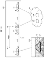
- FIG. 1 is a diagram showing an overall overview of the external world recognition system.
- the external world recognition system in this embodiment aggregates information on road conditions detected by at least one or more information providing vehicles C1 in a server NS, which is an external server, and collects information on road conditions around the information using vehicle C2.
- the server NS distributes the information to the information-using vehicle C2, and the information-using vehicle C2 detects the road surface conditions in more detail using the road surface condition information distributed from the server NS, and controls the vehicle based on the detection results.
- the external world recognition system uses a cloud-type map platform 101 that accumulates, manages, and analyzes the experience information necessary for automatic driving of vehicles on a map.
- the map platform 101 is called traffic experience information on a map, and information such as roads, lanes, driving routes called road-related maps, and facilities and equipment such as signs and traffic lights installed on roads. and past driving experience-related information such as driving history including driving experience information are managed in a two-layered state in which they are associated with each other.
- Road-related maps contain high-precision map information used for automatic driving of vehicles.
- the driving experience information includes, for example, information based on actual driving experience, such as the frequency of occurrence of traffic jams on a predetermined road, time zones, average traveling speed, and the like.
- the map platform 101 receives vehicle information such as lane selection and appropriate speed from a plurality of information providing vehicles C1 (C1a-C1n), and also receives traffic information such as traffic lights and congestion from the infrastructure equipment 111.
- the map platform 101 analyzes big data including vehicle information and traffic information using a server NS connected to an information communication network and a server database DBs that stores various types of information in a readable manner to generate driving experience information. is generated and mapped on the road-related map.
- a plurality of information-providing vehicles C1 and information-using vehicles C2 each use a self-positioning device such as GNSS (Global Navigation Satellite System) to obtain self-location information in the world coordinate system (latitude-longitude coordinate system). to get The information providing vehicle C1 recognizes the external world by means of a three-dimensional measurement device, which is an external world recognition device mounted on the vehicle, and transmits road surface condition information obtained by the external world recognition to the server NS.
- GNSS Global Navigation Satellite System
- the information-using vehicle C2 performs more accurate automatic driving by receiving distribution of traffic experience information on the map from the server NS of the map platform 101 based on the self-location information.
- the information-using vehicle C2 performs vehicle control such as automatic driving control using the three-dimensional measuring device 124, the three-dimensional external world information acquired by the three-dimensional measuring device 124, and the information acquired from the server NS of the map platform 101.
- AD_ECU 122 , MPU 123 that performs various kinds of arithmetic processing, steering device 125 , brake device 126 and drive device 127 that are controlled by control signals from AD_ECU 122 .
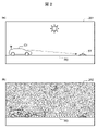
- FIG. 2 is a diagram showing an example of a scene in which structures on the road surface are detected using the external world recognition system according to this embodiment.
- the external world recognition system performs information aggregation processing and information distribution processing.
- the information aggregation process when a structure on the road surface is detected while the information providing vehicle C1 is traveling, the position information of the structure ST on the road surface is transmitted to the server NS, and the information is aggregated by the server NS.
- FIG. 2(a) is a diagram showing an example of information aggregation, and shows a scene in which a structure ST on the road surface is detected while driving in the daytime. If the three-dimensional measurement device of the information providing vehicle C1 is, for example, a stereo camera, the structure ST on the road surface can be easily and accurately detected during travel in bright daytime hours.
- the three-dimensional shape of the road surface unevenness is calculated by the stereo camera, the road surface structure ST is detected, and the relative position and height (shape) of the road surface structure ST with respect to the information providing vehicle C1 are calculated. is estimated. Then, the self-position information of the information providing vehicle C1 measured by the self-position measuring device 315 and the position information of the structure ST on the road surface are transmitted to the server NS by the communication device and stored in the server database DBs as driving experience information. . The position information of the structure ST on the road surface is stored separately for each structure ST on the road surface.
- the server NS receives the position information of the road surface structure ST from a plurality of information providing vehicles C1.
- the server NS aggregates the positional information of the structures ST on the road surface received from the plurality of information providing vehicles C1, and recalculates the positional information for each structure ST on the road surface. In this recalculation, statistical processing is performed to reduce errors in the position information and improve the accuracy of the position information.
- FIG. 2(b) is a diagram showing an example of information distribution, showing a scene in which a structure on the road surface is detected while driving at night.
- the stereo camera of the information-using vehicle C2 may have a low detection success rate and detection accuracy for the structure ST on the road surface, which is the object to be detected, when the vehicle is traveling in the dark at night.
- the stereo camera detects the structures on the road surface based on the positional information.
- the image processing method of the image processing unit for detecting objects is determined, and the structure ST on the road surface is detected by the determined image processing method.
- the detection algorithm such as performing highly accurate image recognition by narrowing the area where image processing is performed by the stereo camera.
- the detection parameters are changed such as by narrowing the range for detecting the peak height position of road unevenness and increasing the threshold value.
- the information-using vehicle C2 does not use the recognition result of the image recognition.
- vehicle control such as warning to passengers, suspension pressure, deceleration, steering, etc. is performed using the position information of the road surface structure ST distributed from the server NS.
- FIG. 3 is a functional block diagram of the information providing vehicle C1, the information using vehicle C2, and the server NS that constitute the external world recognition system of this embodiment.
- the information providing vehicle C1 provides information by passing over the stereo camera 312, which is an example of a three-dimensional measuring device that measures the three-dimensional shape of the road surface and detects structures on the road surface, and the structures ST on the road surface.
- Information is exchanged between a G sensor 313 that detects vehicle vibration applied to the vehicle C1, a self-position measuring device (position information acquisition means) 315 that measures the self coordinate position in the world coordinate system such as a GPS navigation device, and the server NS. It has a road-to-vehicle communication device 317 for transmitting and receiving.
- the information-using vehicle C2 has a stereo camera 322, a self-position measuring device (self-position measuring unit) 325, a road-to-vehicle communication device 324, and a G sensor 323. Further, based on the detection result of the stereo camera 322, A vehicle control device 326 that performs automatic brake control and inter-vehicle distance control ACC, a human-machine interface 327 that warns vehicle occupants, a vehicle route generation device 328 that generates a route to a destination, and information-using vehicle C2. It has a vehicle database DBc that stores information such as the coordinate position and the position and size of the structure ST on the road surface.
- the stereo camera 322 has a pair of left and right in-vehicle cameras that capture images in front of the vehicle, and a camera control unit that performs image processing of the in-vehicle cameras and captured images.
- the camera control section has hardware such as a CPU and a memory, and a software program executed by the hardware, and implements the control functions of the following sections through cooperation between the hardware and software.
- the camera control unit of the stereo camera 322 includes an image processing unit that performs image processing for detecting structures on the road surface from images captured by the vehicle-mounted camera, and based on the position information of the structures on the road surface ST received from the server NS. and an image processing method determination unit that changes the image processing method of the image processing unit.
- the server NS includes a communication device 302 that transmits and receives information to and from the road-to-vehicle communication device 317 of the information providing vehicle C1 and to and from the road-to-vehicle communication device 324 of the information-using vehicle C2.
- Statistical analysis of the server database DBs that collects and stores the position information of the provided road surface structure ST in a readable manner and the big data that includes vehicle information and traffic information stored in the server database DBs, It has a data analysis device 303 that generates driving experience information and maps it on a road-related map.
- FIG. 4 is a flowchart for explaining the content of information processing in the information providing vehicle and the server, and shows the content of processing for providing information from the information providing vehicle C1 to the server NS.
- the image pickup unit of the stereo camera 312 picks up an image in front of the vehicle to obtain a picked-up image (S401), and the image processing unit of the stereo camera 312 performs image processing on the picked-up image to generate a parallax image.
- the unevenness of the road surface which is a three-dimensional shape in front of the vehicle, is measured, and the structure ST on the road surface is detected based on the measurement results (S402).
- the stereo camera 312 acquires three-dimensional shapes such as speed bumps and road edge shapes on the road surface, road unevenness data, etc., and information on the positions of the structures ST on the road surface through image processing by the image processing unit.
- the image processing unit of the stereo camera 312 coordinates-transforms the position of the structure ST on the road surface obtained by image processing from the position relative to the own vehicle to the coordinate position of the world coordinate system. Specifically, position information in the world coordinate system corresponding to the imaging position of the own vehicle measured by the self-position measuring device 315 is acquired (S403), and position information in the world coordinate system of the structure ST on the road surface is generated. (S404). Then, the information providing vehicle C1 uses the road-vehicle communication device 317 to transmit the position information of the structure ST on the road surface after the coordinate conversion to the server NS.
- the server NS stores in the server database DBs the positional information of the plurality of road surface structures ST transmitted from the plurality of information providing vehicles C1 or from the same information providing vehicle C1 (S405).
- the server NS stores the position information of the structure ST on the road surface in the server database DBs
- the server NS recalculates the traffic experience information on the map at a predetermined timing and updates it to the latest information.
- the server NS receives the positional information of a plurality of structures ST on the road surface from the information providing vehicle C1
- the server NS organizes the information by adding or deleting the information, collects the information on the same position as the same information, and stores it in the server database. Store in DBs.
- the server NS statistically analyzes the positional information of the structures ST on the road surface transmitted from the plurality of information providing vehicles C1 and stored in the server database DBs as big data by the data analysis device 303, and creates and updates the driving experience information. , is mapped onto a road-related map, and stored in the server database DBs as traffic experience information on the map (S406).
- FIG. 5 is a flowchart for explaining a normal image processing method in a stereo camera, and shows an example of processing performed by the stereo camera of the information providing vehicle C1.
- a pair of left and right captured images are captured by the imaging unit of the stereo camera 312 (S501), and a parallax image is generated from the pair of captured images (S502). Then, an image processing area for image processing is set in the parallax image (S503).
- an image processing area for image processing is set in the parallax image (S503).
- an area on the tire traveling path through which the left and right tires of the information providing vehicle C1 pass is set as an image processing area.
- FIG. 8 is a diagram showing an example of setting an image processing area in a parallax image, and is a diagram explaining a method of setting the image processing area.
- a parallax image 801 generated by imaging the front of the vehicle with a stereo camera shows a traveling road surface 811 of a road R0 and white lines 812 on both left and right sides thereof.
- Processing areas 821 and 822 are set along the vehicle traveling path. The processing areas 821 and 822 are set so as to extend in the depth direction (advance direction) with a predetermined width on the tire travel path through which the left and right tires pass as the vehicle travel path.
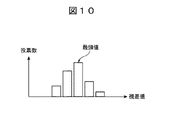
- FIG. 10 is a diagram for explaining a method of searching in the lateral direction to determine the parallax of unevenness of the road surface.
- the lateral search is performed over the entire depth direction of the processing areas 821 and 822 .
- the parallax values for each lateral search calculated in S504 are arranged in the depth direction of the processing area, and the peak position of the unevenness height of the road surface is calculated (S505). For example, a peak position whose height from the road surface reference plane has a value greater than a predetermined determination threshold value can be determined as the position of the structure on the road surface ST.
- a process of analyzing the stability of peak position determination is performed (S506).
- this stability analysis processing it is determined whether or not the peak position moves according to the movement of the own vehicle.
- the distance between the own vehicle and the structure ST on the road surface is calculated (S507), and the final output is produced (S508).
- S508 a process of outputting a warning to the occupants and an emergency braking signal to the vehicle control device is performed, and the vehicle control device controls the warning and emergency braking, but is not limited to this.
- the vehicle control device may issue an alarm or an emergency brake.
- FIG. 6 is a flow chart explaining the contents of information processing in the server NS and the information-using vehicle C2.
- the information-using vehicle C2 measures its own position with the self-position measuring device 325, and transmits the self-position information to the server NS (S601).
- the server NS searches the server database DBs and extracts the position information of structures on the road existing around the self-position of the information-using vehicle C2 (S602). . Then, the position information is distributed to the information-using vehicle C2 that has provided the self-position information.
- the information-using vehicle C2 When the information-using vehicle C2 receives the position information of the structures ST existing on the road surface around its own position from the server NS, it stores it in the vehicle database DBc (S603). Then, the stereo camera 322 picks up an image in front of the vehicle, acquires the picked-up image (S604), and performs image processing using the position information of the structure on the road surface ST received from the server NS stored in the vehicle database DBc. A structure ST on the road surface is detected (S605).
- the image processing method is determined based on the position information of the structure ST on the road surface received from the server NS. For example, first, a process of searching the vehicle database DBc using position information of structures on the road surface around the self-position measured by the self-position measuring device 325 is performed. When the road surface structure ST, which is the object to be detected, exists in the vicinity of the self position, the image processing method determination unit of the stereo camera 322 changes at least one of the image processing algorithm and parameters. done.
- the stereo camera 322 performs image processing using the changed algorithm and parameters, and detects the structure ST on the road surface.
- the stereo camera 322 changes the algorithm or parameters based on the position information of the structure ST on the road surface received from the server NS, analyzes the image processing area corresponding to the position in detail, and adjusts the detection accuracy. .
- the information-using vehicle C2 performs vehicle control using the detection result of the structure ST on the road surface by the stereo camera 322 (S606).
- vehicle control process of S606 for example, at least one of adjustment of the vehicle speed passing the road surface structure ST, route setting, and warning to the occupant is performed.
- the vehicle control device 326 searches the vehicle database DBc for information on the road surface structure ST around the self-position measured by the self-position measuring device 325, and searches the vehicle database DBc for information on the road surface structure ST that is stored corresponding to the road surface structure ST. When it is determined that the speed of the own vehicle exceeds the speed information, deceleration control is performed.
- the speed is decelerated to a speed at which the speed bump can be passed safely or comfortably, or the upper limit speed of the inter-vehicle distance control ACC is set. Change to a speed that you can safely or comfortably pass.
- the vehicle route generation device 328 sets a route so that the information-using vehicle C2 passes through a road or lane on which it can travel safely or comfortably.
- the human-machine interface 327 determines that the speed of the information-using vehicle C2 is excessive, it sounds a warning alarm or displays a warning on the monitor to warn the occupants.
- the damping value may be adjusted to suppress the behavior of the vehicle when passing through a speed bump.
- FIG. 7 is a flowchart for explaining the processing by the stereo camera of the information-using vehicle C2. The description of the configuration similar to that of the flowchart shown in FIG. 5 will be omitted.
- the stereo camera 322 changes the image processing method according to whether or not the structure ST on the road surface exists around its own position.
- the stereo camera 322 performs normal image processing using the same algorithm and parameters as those of the information providing vehicle C1 when the structure ST on the road surface does not exist around its own position.
- image processing is performed by changing at least one of the image processing algorithm and parameters as compared with the case where the road surface structure ST does not exist.
- FIG. 9 is a diagram for explaining an image processing method using position information, and shows an example of narrowing down the image processing area.
- the image processing method determining unit of the stereo camera 322 performs a process of narrowing down the image processing area of road unevenness based on the positional information of the road surface structure ST received from the server NS.
- a second image processing area 911 corresponding to the position of the structure ST on the road surface on the tire traveling path , 912 is performed.
- the self-position of the vehicle estimated by receiving radio waves from GPS or base stations, the update cycle of GPS information, the vehicle speed at that time, the position information of the road surface structure ST received from the server NS, the position information of the road surface structure ST received from the server NS, map estimation error (depending on radio wave conditions and the number of detected base stations), information transmission in the in-vehicle communication environment, and time-world coordinate transformation (imaging and Captured by a camera by converting positional information of an object into a three-dimensional to two-dimensional coordinate system that considers time-varying information such as position measurement and vehicle speed, and the coordinate system of the map and the imaging coordinate system of the camera.
- the second image processing areas 911 and 912 are set shorter in length in the depth direction than the first image processing areas 821 and 822, and have a size and shape that cover the road surface structure ST in the parallax image. there is In this way, by narrowing down the image processing area to make it smaller, the image processing load can be reduced. Therefore, more detailed image processing can be performed in a short time with limited hardware resources, and the structure ST on the road surface, which is the object to be detected, can be detected with high accuracy.
- FIG. 11 is a diagram showing the peak detection results of road surface irregularities, showing the detected values of the road surface height in the depth direction of the tire traveling path.
- the horizontal axis is the distance (m) in the depth direction
- the vertical axis is the road surface height (cm) detected by the stereo camera 322 .
- the image processing method determination unit of the stereo camera 322 determines the peak position of the road unevenness in the first detection range set along the depth direction of the tire travel path when the structure ST on the road surface does not exist around the self position. However, when the structure ST on the road surface exists around the self position, the image processing algorithm or parameters of the image processing unit are changed, and a second detection range corresponding to the position of the structure ST on the road surface on the tire traveling path is detected. , the peak position of road unevenness is determined (S505A).
- the image processing method determination unit of the stereo camera 322 sets the determination threshold for determining the peak position of road surface unevenness in the second detection range to be higher than the determination threshold for determining the peak position of road surface unevenness in the first detection range.
- a large value is set (S505A).
- a process of outputting an alarm or emergency braking signal to the vehicle control device, or a process of outputting only information on the distance between the own vehicle and the structure ST on the road surface is performed. Further, it is determined whether or not the reliability of the captured image captured by the stereo camera 322 is equal to or higher than the threshold. For example, when the reliability is lower than the threshold value due to the weather or external light conditions, the processing in S501 to S507 is skipped, and the final output is made based on the position information of the structure ST on the road surface distributed from the server NS. Based on the output, vehicle control such as warning to passengers, suspension pressure, deceleration, and steering is performed.
- step S509A for calculating verification information of the structure ST on the road surface is provided.
- the stereo camera 322 converts the position of the structure ST on the road surface detected by the image processing into the coordinate position of the world coordinate system using the self-position information obtained by the self-position measuring device 325. , acquires information on the position where the behavior of the vehicle is detected when the vehicle passes over the structure ST on the road surface.
- the process of converting the position of the structure ST on the road surface into the world coordinates is based on the distance to the structure ST on the road surface detected by image processing, (1) the vehicle speed at the time of imaging, and (2) the imaging unit of the stereo camera 322. (3) self-location information by the self-location measurement device 325; (4) acquisition timing of self-location information by the self-location measurement device 325; (5) communication delay speed of in-vehicle equipment; Time-world coordinate conversion processing converts position information into a three-dimensional to two-dimensional coordinate system, taking into consideration time-varying information such as imaging, position measurement, and vehicle speed, as well as the coordinate system of the map and the coordinate system captured by the camera. is.
- the behavior of the vehicle when the vehicle passes over the structure ST on the road surface can be detected by the stereo camera 322 by detecting the vertical movement of the captured image, and by the vehicle-mounted sensors such as the G sensor, pitching, vertical acceleration, A change in suspension pressure may be detected.
- the position of the road surface structure ST detected by the stereo camera 322 of the information using vehicle C2 is verified from the own vehicle behavior, and the verification information is transmitted to the server NS.
- the server NS can improve the estimation accuracy of the position of the road surface structure ST using the verification information.
- FIG. 13 is a flow chart for explaining the processing contents of the external world recognition system in the second embodiment
- FIG. 14 is a diagram showing an example of a situation in which the processing shown in FIG. 13 is performed.
- a characteristic feature of this embodiment is that although the information providing vehicle C1 cannot detect the structure ST on the road surface with the stereo camera 312, it detects vehicle vibration in the vertical direction due to passing over the structure ST on the road surface. By detecting the vibration, the server NS performs image processing using an image obtained by picking up the vibration detection position.
- the stereo camera 312 of the information providing vehicle C1 acquires captured images captured during travel and stores them in the vehicle database (S1301). Then, for example, when the G sensor 313 detects vibration equal to or greater than a preset threshold for detecting vertical vehicle vibration due to passing over the road surface structure ST (S1302), the self-position measuring device detects The position information of the vibration detection point Pn is acquired based on the self-position information (S1303).
- the method of detecting vehicle vibration is not limited to the G sensor 313. For example, vertical movement of images captured by the stereo camera 312, pitching by an in-vehicle sensor such as a gyro sensor, vertical acceleration, and changes in suspension pressure are used. good too.
- the stereo camera 312 searches the inside of the vehicle database and extracts the captured image of the vibration detection point Pn from the captured images stored in the vehicle database (S1304).
- an image captured when t time goes back from the time when the vehicle vibration in the vertical direction is detected to the position Pn-1 where the stereo camera 312 captures the image of the vibration detection point Pn. is extracted as an image in which the vibration detection point Pn is captured.
- the road-to-vehicle communication device 317 receives from the stereo camera 312 the information of the vibration detection point Pn and the imaged image of the point, and transmits the information to the server NS.
- the data analysis device 303 detects the structure ST on the road surface from the captured image of the vibration detection point Pn.
- image processing is performed (S1305).
- the image processing performed by the server NS differs from the image processing performed by the stereo camera 312 in terms of processing content, and is more detailed and advanced than the image processing performed in the stereo camera 312 .
- the server NS does not have processing time restrictions and has higher specifications than the stereo camera 312 and abundant hardware and software resources. Image processing of content can be performed. Therefore, it is possible to detect the road surface structure ST that could not be detected by the stereo camera 312, and to verify the reason why the stereo camera 312 could not detect it.
- the server NS stores the detection result of the road surface structure ST by the image processing of the data analysis device 303 and the position information of the vibration detection point Pn in the server database DBs (S1306).
- the position information is analyzed and recalculated (S1307).
- the structure ST on the road surface which could not be detected by the stereo camera 312
- the structure ST on the road surface can be detected by the image processing in the server NS, and the road surface stored in the server database DBs can be detected.
- the accuracy of the position information of the upper structure ST can be made higher.
- the image processing for verification is performed in the server NS.
- Image processing for verification may be performed in the server NS also when the structure ST on the road surface is detected by .
- the case of the information providing vehicle C1 has been described as an example. may be used to perform image processing in the server NS.
- FIG. 15 is a flowchart for explaining the processing contents of the external world recognition system in the third embodiment, and shows an analysis method based on the information on the position of structures on the road surface and vehicle vibration.
- a characteristic feature of this embodiment is that, in addition to the positional information of the structure ST on the road surface, information about the degree of influence on vehicle vibration when the vehicle actually passes is stored in the server, and the information-using vehicle C2 detects the road surface. It is used for vehicle control when passing over the upper structure ST.
- the information providing vehicle C1 acquires a captured image (S1501), and performs image processing to detect the structure ST on the road surface, determine the distance to the structure ST on the road surface, and the height of the structure ST from the road surface reference plane. is measured (S1502).
- the road surface reference plane can be obtained, for example, from the average position of road unevenness in the depth direction.
- the information providing vehicle C1 uses the G sensor 323 to detect vibration when it passes over the structure ST on the road surface (S1503), and acquires position information of the vibration detection point (S1504).
- the degree of influence on the vehicle vibration is calculated based on the magnitude of the vibration detected by the G sensor 323, and the position information of the structure ST on the road surface, the position of the vibration detection point, and the information on the degree of influence on the vehicle vibration are obtained.
- the information is sent to the server NS, and the server NS stores this information in the server database DBs (S1505).
- the server NS aggregates the position information of the road surface structure ST stored in the server database DBs, the position of the vibration detection point, and the degree of influence on the vehicle vibration, and the data analysis device 303 statistically analyzes the big data. , update the driving experience information, map it on the road-related map, and create the traffic experience information on the map.
- the server NS After storing the position information of the road surface structure ST in the server database DBs, the server NS recalculates the traffic experience information on the map at a predetermined timing in order to update the information to the latest information (S1506).
- the server NS When the server NS receives the self-position information from the information providing vehicle C1, the server NS uses the position information of the structure ST existing on the road surface around the self-position of the information-using vehicle C2 and the information on the degree of influence on the vehicle vibration. Send to vehicle C2.
- the information-using vehicle C2 slows down the running speed and adjusts the suspension based on the position information of the road surface structures ST existing around its own position and the information on the degree of influence on the vehicle vibration so as to reduce the vibration of the vehicle. It performs vehicle control such as damping force adjustment.
- the information on the degree of influence of the vehicle vibration by the structure ST on the road surface can be provided to the information-using vehicle C2. can be performed, and the passenger's riding comfort can be improved.
- C1 Information providing vehicle C2 Information using vehicle (own vehicle) NS server (external server) DBs Server database DBc Vehicle database ST On-road structure 322 Stereo camera 323 G sensor 324 Road-to-vehicle communication device (vehicle communication unit) 325 self-position measuring devices 821, 822 first image processing areas 911, 912 second image processing areas
Landscapes
- Engineering & Computer Science (AREA)
- Physics & Mathematics (AREA)
- General Physics & Mathematics (AREA)
- Computing Systems (AREA)
- Theoretical Computer Science (AREA)
- Analytical Chemistry (AREA)
- Chemical & Material Sciences (AREA)
- Atmospheric Sciences (AREA)
- Life Sciences & Earth Sciences (AREA)
- Business, Economics & Management (AREA)
- General Health & Medical Sciences (AREA)
- Multimedia (AREA)
- Development Economics (AREA)
- Accounting & Taxation (AREA)
- Biomedical Technology (AREA)
- Health & Medical Sciences (AREA)
- Economics (AREA)
- General Business, Economics & Management (AREA)
- Operations Research (AREA)
- Computer Networks & Wireless Communication (AREA)
- Signal Processing (AREA)
- Mathematical Physics (AREA)
- Educational Administration (AREA)
- Educational Technology (AREA)
- Traffic Control Systems (AREA)
Abstract
The problem of the present invention is to provide an external recognition system capable of accurately detecting unevenness of a road surface in front of a vehicle. The external recognition system according to the present invention recognizes the three-dimensional shape of a road surface on which a subject vehicle C2 is traveling, and the subject vehicle C2 comprises: an image processing unit that executes image processing of detecting a road surface structure from an image captured by an in-vehicle camera; a vehicle communication unit that receives position information of the road surface structure ST from an external server NS; and an image processing method determination unit that changes the image processing method of the image processing unit on the basis of the position information of the road surface structure ST received by the vehicle communication unit.
Description
本発明は、車両が走行する路面の凹凸を認識する外界認識システムに関する。
The present invention relates to an external recognition system that recognizes the unevenness of the road surface on which a vehicle travels.
従来から車載カメラにより車両前方を撮像してスピードバンプなどの路面上の構造物を認識する外界認識技術が存在する。そして、他車両が走行して取得した外界認識情報を、自車両の走行制御に利用するシステムが提案されている(特許文献1)。
Conventionally, there is an external recognition technology that uses an in-vehicle camera to image the front of the vehicle and recognizes structures on the road surface such as speed bumps. A system has been proposed in which external world recognition information acquired by another vehicle is used for driving control of the own vehicle (Patent Document 1).
車載カメラ等の外界認識センサによって検知を行う場合に、夜間、逆光、雨天などの環境状況によっては路面上構造物などの路面の凹凸を正確に認識できないことがある。また、他車両により取得した外界認識情報を自車両の走行制御に利用する場合、路面上構造物の正確な位置の情報が必要となるが、GPS等の位置検出手段は、周囲の環境に影響を受けやすく、検出精度が不安定であり、検出精度にも限界がある。
When performing detection with an external recognition sensor such as an in-vehicle camera, it may not be possible to accurately recognize the unevenness of the road surface, such as structures on the road surface, depending on environmental conditions such as nighttime, backlight, and rainy weather. In addition, when the external world recognition information acquired by other vehicles is used for driving control of the own vehicle, accurate position information of structures on the road surface is required. detection accuracy is unstable, and detection accuracy is limited.
本発明は、上記の点に鑑みてなされたものであり、その目的とするところは、車両前方の路面凹凸を高精度に検知することができる外界認識システムを提供することである。
The present invention has been made in view of the above points, and its object is to provide an external world recognition system that can detect road surface unevenness in front of the vehicle with high accuracy.
上記課題を解決する本発明の外界認識システムは、
自車両が走行する路面の3次元形状を認識する外界認識システムであって、
前記自車両は、
車載カメラで撮像した撮像画像から路面上構造物を検出する画像処理を行う画像処理部と、
外部サーバから前記路面上構造物の位置情報を受信する車両通信部と、
該車両通信部により受信した前記路面上構造物の位置情報に基づいて前記画像処理部の画像処理方法を変更する画像処理方法決定部と、
を備えることを特徴とする。 The external world recognition system of the present invention for solving the above problems,
An external world recognition system that recognizes the three-dimensional shape of the road surface on which the vehicle travels,
The vehicle is
an image processing unit that performs image processing for detecting structures on the road surface from images captured by an in-vehicle camera;
a vehicle communication unit that receives position information of the structure on the road surface from an external server;
an image processing method determination unit that changes the image processing method of the image processing unit based on the position information of the structure on the road surface received by the vehicle communication unit;
characterized by comprising
本発明によれば、車両前方の路面凹凸を高精度に検知することができる。本発明に関連する更なる特徴は、本明細書の記述、添付図面から明らかになるものである。また、上記した以外の、課題、構成及び効果は、以下の実施形態の説明により明らかにされる。
According to the present invention, road surface unevenness in front of the vehicle can be detected with high accuracy. Further features related to the present invention will become apparent from the description of the specification and the accompanying drawings. Further, problems, configurations, and effects other than those described above will be clarified by the following description of the embodiments.
次に、本発明の実施形態について図面を用いて説明する。
Next, an embodiment of the present invention will be described with reference to the drawings.
最初に本実施形態の外界認識システムの概要について説明する。図1は、外界認識システムの全体概要を示す図である。本実施形態における外界認識システムは、少なくとも1台以上の情報提供車両C1によって検知された路面状況の情報を、外部サーバであるサーバNSに集約し、情報利用車両C2の周辺の路面状況の情報をサーバNSから情報利用車両C2に配信し、サーバNSから配信された路面状況の情報を用いて情報利用車両C2が路面状況をさらに詳細に検知し、その検知結果に基づいて車両制御を行うシステムである。
First, an outline of the external world recognition system of this embodiment will be explained. FIG. 1 is a diagram showing an overall overview of the external world recognition system. The external world recognition system in this embodiment aggregates information on road conditions detected by at least one or more information providing vehicles C1 in a server NS, which is an external server, and collects information on road conditions around the information using vehicle C2. In this system, the server NS distributes the information to the information-using vehicle C2, and the information-using vehicle C2 detects the road surface conditions in more detail using the road surface condition information distributed from the server NS, and controls the vehicle based on the detection results. be.
外界認識システムは、車両の自動運転に必要な経験情報を地図上に集積、管理、分析するクラウド型の地図プラットフォーム101を利用する。地図プラットフォーム101は、地図上の交通経験情報と称されるものであり、道路関連地図と称される道路・車線・走行経路や道路に設置されている標識や信号機などの施設・器物などの情報を含む地図情報と、運転経験情報を含むドライブ履歴など過去における走行経験関連情報とが互いに関連付けされた2階層の状態で管理している。道路関連地図には、車両の自動運転に用いられる高精度な地図情報が含まれている。運転経験情報には、例えば所定の道路における渋滞の発生頻度や時間帯、平均的な走行速度などの実際の運転経験に基づく情報が含まれる。
The external world recognition system uses a cloud-type map platform 101 that accumulates, manages, and analyzes the experience information necessary for automatic driving of vehicles on a map. The map platform 101 is called traffic experience information on a map, and information such as roads, lanes, driving routes called road-related maps, and facilities and equipment such as signs and traffic lights installed on roads. and past driving experience-related information such as driving history including driving experience information are managed in a two-layered state in which they are associated with each other. Road-related maps contain high-precision map information used for automatic driving of vehicles. The driving experience information includes, for example, information based on actual driving experience, such as the frequency of occurrence of traffic jams on a predetermined road, time zones, average traveling speed, and the like.
地図プラットフォーム101には、複数の情報提供車両C1(C1a-C1n)から車線選択や適性速度などの車両情報が入力され、また、インフラ設備111から信号や渋滞などの交通情報が入力される。地図プラットフォーム101は、情報通信ネートワークに接続されたサーバNSと、種々の情報を読み出し可能に格納するサーバデータベースDBsを用いて、車両情報と交通情報を含むビッグデータの解析を行い、運転経験情報を生成し、道路関連地図上にマッピングを行う。
The map platform 101 receives vehicle information such as lane selection and appropriate speed from a plurality of information providing vehicles C1 (C1a-C1n), and also receives traffic information such as traffic lights and congestion from the infrastructure equipment 111. The map platform 101 analyzes big data including vehicle information and traffic information using a server NS connected to an information communication network and a server database DBs that stores various types of information in a readable manner to generate driving experience information. is generated and mapped on the road-related map.
複数の情報提供車両C1と情報利用車両C2は、それぞれGNSS(Global Navigation Satellite System/全球測位衛星システム)等の自己位置計測装置を利用して世界座標系(緯度経度座標系)における自己位置の情報を取得する。情報提供車両C1は、自車に搭載された外界認識装置である3次元計測装置により外界認識を行い、その外界認識により取得した路面状況の情報をサーバNSに送信する。
A plurality of information-providing vehicles C1 and information-using vehicles C2 each use a self-positioning device such as GNSS (Global Navigation Satellite System) to obtain self-location information in the world coordinate system (latitude-longitude coordinate system). to get The information providing vehicle C1 recognizes the external world by means of a three-dimensional measurement device, which is an external world recognition device mounted on the vehicle, and transmits road surface condition information obtained by the external world recognition to the server NS.
情報利用車両C2は、自己位置情報に基づいて地図プラットフォーム101のサーバNSから地図上の交通経験情報の配信を受けることにより、より高精度な自動運転を行う。情報利用車両C2は、3次元計測装置124と、3次元計測装置124により取得した3次元の外界情報と地図プラットフォーム101のサーバNSから取得した情報とを用いて自動運転制御等の車両制御を行うAD_ECU122と、各種の演算処理を行うMPU123と、AD_ECU122からの制御信号により制御されるステアリング装置125、ブレーキ装置126、駆動装置127を備えている。
The information-using vehicle C2 performs more accurate automatic driving by receiving distribution of traffic experience information on the map from the server NS of the map platform 101 based on the self-location information. The information-using vehicle C2 performs vehicle control such as automatic driving control using the three-dimensional measuring device 124, the three-dimensional external world information acquired by the three-dimensional measuring device 124, and the information acquired from the server NS of the map platform 101. AD_ECU 122 , MPU 123 that performs various kinds of arithmetic processing, steering device 125 , brake device 126 and drive device 127 that are controlled by control signals from AD_ECU 122 .
図2は、本実施形態における外界認識システムを用いた路面上構造物を検出するシーンの例を示す図である。
FIG. 2 is a diagram showing an example of a scene in which structures on the road surface are detected using the external world recognition system according to this embodiment.
外界認識システムでは、情報集約処理と情報配信処理が行われる。情報集約処理では、情報提供車両C1の走行中に路面上構造物を検知した場合に、その路面上構造物STの位置情報がサーバNSに送信され、サーバNSで情報の集約がなされる。図2(a)は、情報集約の一例を示す図であり、昼間の走行中に路面上構造物STを検知するシーンを示している。情報提供車両C1の3次元計測装置が例えばステレオカメラである場合、昼間の明るい時間帯の走行において、路面上構造物STを容易かつ正確に検知することができる。
The external world recognition system performs information aggregation processing and information distribution processing. In the information aggregation process, when a structure on the road surface is detected while the information providing vehicle C1 is traveling, the position information of the structure ST on the road surface is transmitted to the server NS, and the information is aggregated by the server NS. FIG. 2(a) is a diagram showing an example of information aggregation, and shows a scene in which a structure ST on the road surface is detected while driving in the daytime. If the three-dimensional measurement device of the information providing vehicle C1 is, for example, a stereo camera, the structure ST on the road surface can be easily and accurately detected during travel in bright daytime hours.
情報提供車両C1では、ステレオカメラにより路面の3次元形状である路面凹凸が計算され、路面上構造物STの検知と、情報提供車両C1に対する路面上構造物STの相対位置および高さ(形状)の推定が行われる。そして、自己位置計測装置315によって計測された情報提供車両C1の自己位置情報と、路面上構造物STの位置情報が通信装置によってサーバNSに送信され、運転経験情報としてサーバデータベースDBsに格納される。路面上構造物STの位置情報は、路面上構造物STごとに分けて格納される。
In the information providing vehicle C1, the three-dimensional shape of the road surface unevenness is calculated by the stereo camera, the road surface structure ST is detected, and the relative position and height (shape) of the road surface structure ST with respect to the information providing vehicle C1 are calculated. is estimated. Then, the self-position information of the information providing vehicle C1 measured by the self-position measuring device 315 and the position information of the structure ST on the road surface are transmitted to the server NS by the communication device and stored in the server database DBs as driving experience information. . The position information of the structure ST on the road surface is stored separately for each structure ST on the road surface.
サーバNSには、複数の情報提供車両C1から路面上構造物STの位置情報が送信される。サーバNSでは、複数の情報提供車両C1から受信した路面上構造物STの位置情報を集約し、路面上構造物STごとに位置情報の再計算を行う。この再計算では、統計処理により位置情報の誤差を減らし、位置情報の確度を向上させる処理が行われる。
The server NS receives the position information of the road surface structure ST from a plurality of information providing vehicles C1. The server NS aggregates the positional information of the structures ST on the road surface received from the plurality of information providing vehicles C1, and recalculates the positional information for each structure ST on the road surface. In this recalculation, statistical processing is performed to reduce errors in the position information and improve the accuracy of the position information.
情報配信処理では、情報利用車両C2からサーバNSに自己位置情報を送信することにより、サーバNSから情報利用車両C2の周辺の路面状況についての情報が情報利用車両C2に配信される。図2(b)は、情報配信の一例を示す図であり、夜間の走行中に路面上構造物を検出するシーンを示している。情報利用車両C2のステレオカメラは、夜の暗い時間帯の走行では、検知対象物である路面上構造物STの検知の成功率や検知精度が低くなるおそれがある。
In the information distribution process, by transmitting the self-location information from the information-using vehicle C2 to the server NS, the server NS distributes information about road conditions around the information-using vehicle C2 to the information-using vehicle C2. FIG. 2(b) is a diagram showing an example of information distribution, showing a scene in which a structure on the road surface is detected while driving at night. The stereo camera of the information-using vehicle C2 may have a low detection success rate and detection accuracy for the structure ST on the road surface, which is the object to be detected, when the vehicle is traveling in the dark at night.
これに対して、本実施形態では、情報利用車両C2は、サーバNSから自己位置周辺に存在する路面上構造物の位置情報の配信を受けると、ステレオカメラによりその位置情報に基づいて路面上構造物を検知するための画像処理部の画像処理方法を決定し、その決定した画像処理方法により路面上構造物STの検知を行う。例えば、路面上構造物STのより精度の高い位置情報をサーバNSから得られた場合には、ステレオカメラにより画像処理を行う領域を狭めて高精度の画像認識を行うなどの検知アルゴリズムの変更や、路面凹凸のピーク高さ位置を検知する範囲を狭めて閾値を上げる等の検知パラメータの変更が行われる。また、情報利用車両C2は、天候や外光条件などにより、ステレオカメラで路面上構造物STを検知できなかった場合や、検出精度が低い場合には、画像認識による認識結果は使用せずに、サーバNSから配信された路面上構造物STの位置情報を用いて乗員への警報、サスペンション圧、減速、操舵などの車両制御を行う。
On the other hand, in this embodiment, when the information-using vehicle C2 receives the distribution of the positional information of the structures on the road surface existing around its own position from the server NS, the stereo camera detects the structures on the road surface based on the positional information. The image processing method of the image processing unit for detecting objects is determined, and the structure ST on the road surface is detected by the determined image processing method. For example, when more accurate position information of the structure ST on the road surface is obtained from the server NS, it is possible to change the detection algorithm, such as performing highly accurate image recognition by narrowing the area where image processing is performed by the stereo camera. , the detection parameters are changed such as by narrowing the range for detecting the peak height position of road unevenness and increasing the threshold value. Further, when the stereo camera cannot detect the structure ST on the road surface due to the weather or outside light conditions, or when the detection accuracy is low, the information-using vehicle C2 does not use the recognition result of the image recognition. , vehicle control such as warning to passengers, suspension pressure, deceleration, steering, etc. is performed using the position information of the road surface structure ST distributed from the server NS.
図3は、本実施形態の外界認識システムを構成する情報提供車両C1、情報利用車両C2、サーバNSの機能ブロック図である。
情報提供車両C1は、走行路面の3次元形状を計測して路面上構造物を検知する3次元計測装置の一例であるステレオカメラ312と、路面上構造物STの上を通過することによって情報提供車両C1に加わる車両振動を検知するGセンサ313と、GPSナビ装置などの世界座標系における自己の座標位置を計測する自己位置計測装置(位置情報取得手段)315と、サーバNSとの間で情報の送受信を行う路車間通信装置317を有する。 FIG. 3 is a functional block diagram of the information providing vehicle C1, the information using vehicle C2, and the server NS that constitute the external world recognition system of this embodiment.
The information providing vehicle C1 provides information by passing over thestereo camera 312, which is an example of a three-dimensional measuring device that measures the three-dimensional shape of the road surface and detects structures on the road surface, and the structures ST on the road surface. Information is exchanged between a G sensor 313 that detects vehicle vibration applied to the vehicle C1, a self-position measuring device (position information acquisition means) 315 that measures the self coordinate position in the world coordinate system such as a GPS navigation device, and the server NS. It has a road-to-vehicle communication device 317 for transmitting and receiving.
情報提供車両C1は、走行路面の3次元形状を計測して路面上構造物を検知する3次元計測装置の一例であるステレオカメラ312と、路面上構造物STの上を通過することによって情報提供車両C1に加わる車両振動を検知するGセンサ313と、GPSナビ装置などの世界座標系における自己の座標位置を計測する自己位置計測装置(位置情報取得手段)315と、サーバNSとの間で情報の送受信を行う路車間通信装置317を有する。 FIG. 3 is a functional block diagram of the information providing vehicle C1, the information using vehicle C2, and the server NS that constitute the external world recognition system of this embodiment.
The information providing vehicle C1 provides information by passing over the
情報利用車両C2は、ステレオカメラ322と、自己位置計測装置(自己位置計測部)325と、路車間通信装置324と、Gセンサ323を有しており、更に、ステレオカメラ322の検知結果に基づいて自動ブレーキ制御や車間距離制御ACCを行う車両制御装置326と、車両の乗員に警報を行うヒューマンマシンインターフェース327と、目的地までの経路を生成する車両経路生成装置328と、情報利用車両C2の座標位置や路面上構造物STの位置や大きさなどの情報を格納する車両データベースDBcを有する。ステレオカメラ322は、車両前方を撮像する左右一対の車載カメラと、車載カメラおよび撮像画像の画像処理などの制御を行うカメラ制御部とを有している。カメラ制御部は、CPUやメモリなどのハードウエアと、ハードウエアによって実行されるソフトウエアプログラムを有しており、これらハードウエアとソフトウエアの協働により下記各部の制御機能を具現化する。ステレオカメラ322のカメラ制御部は、車載カメラで撮像された撮像画像から路面上構造物を検出する画像処理を行う画像処理部と、サーバNSから受信した路面上構造物STの位置情報に基づいて画像処理部の画像処理方法を変更する画像処理方法決定部とを備えている。
The information-using vehicle C2 has a stereo camera 322, a self-position measuring device (self-position measuring unit) 325, a road-to-vehicle communication device 324, and a G sensor 323. Further, based on the detection result of the stereo camera 322, A vehicle control device 326 that performs automatic brake control and inter-vehicle distance control ACC, a human-machine interface 327 that warns vehicle occupants, a vehicle route generation device 328 that generates a route to a destination, and information-using vehicle C2. It has a vehicle database DBc that stores information such as the coordinate position and the position and size of the structure ST on the road surface. The stereo camera 322 has a pair of left and right in-vehicle cameras that capture images in front of the vehicle, and a camera control unit that performs image processing of the in-vehicle cameras and captured images. The camera control section has hardware such as a CPU and a memory, and a software program executed by the hardware, and implements the control functions of the following sections through cooperation between the hardware and software. The camera control unit of the stereo camera 322 includes an image processing unit that performs image processing for detecting structures on the road surface from images captured by the vehicle-mounted camera, and based on the position information of the structures on the road surface ST received from the server NS. and an image processing method determination unit that changes the image processing method of the image processing unit.
サーバNSは、情報提供車両C1の路車間通信装置317との間、および情報利用車両C2の路車間通信装置324との間で情報の送受信を行う通信装置302と、複数の情報提供車両C1から提供を受けた路面上構造物STの位置情報を集約して読み出し可能に格納するサーバデータベースDBsと、サーバデータベースDBs内に格納されている車両情報と交通情報を含むビッグデータの統計解析を行い、運転経験情報を生成し、道路関連地図上にマッピングを行うデータ解析装置303を有する。
The server NS includes a communication device 302 that transmits and receives information to and from the road-to-vehicle communication device 317 of the information providing vehicle C1 and to and from the road-to-vehicle communication device 324 of the information-using vehicle C2. Statistical analysis of the server database DBs that collects and stores the position information of the provided road surface structure ST in a readable manner and the big data that includes vehicle information and traffic information stored in the server database DBs, It has a data analysis device 303 that generates driving experience information and maps it on a road-related map.
図4は、情報提供車両とサーバにおける情報処理の内容を説明するフローチャートであり、情報提供車両C1からサーバNSに情報を提供する処理の内容を示すものである。
FIG. 4 is a flowchart for explaining the content of information processing in the information providing vehicle and the server, and shows the content of processing for providing information from the information providing vehicle C1 to the server NS.
情報提供車両C1では、ステレオカメラ312の撮像部により車両前方を撮像して撮像画像を取得し(S401)、ステレオカメラ312の画像処理部により撮像画像の画像処理を行い、視差画像を生成して車両前方の3次元形状である路面凹凸を計測し、計測結果に基づいて路面上構造物STを検知する(S402)。ステレオカメラ312は、画像処理部の画像処理により、路面上のスピードバンプや道路端の形状、あるいは路面凹凸データ等の3次元形状と、路面上構造物STの位置の情報を取得する。
In the information providing vehicle C1, the image pickup unit of the stereo camera 312 picks up an image in front of the vehicle to obtain a picked-up image (S401), and the image processing unit of the stereo camera 312 performs image processing on the picked-up image to generate a parallax image. The unevenness of the road surface, which is a three-dimensional shape in front of the vehicle, is measured, and the structure ST on the road surface is detected based on the measurement results (S402). The stereo camera 312 acquires three-dimensional shapes such as speed bumps and road edge shapes on the road surface, road unevenness data, etc., and information on the positions of the structures ST on the road surface through image processing by the image processing unit.
ステレオカメラ312の画像処理部は、画像処理により取得した路面上構造物STの位置を、自車に対する相対位置から世界座標系の座標位置に座標変換する。具体的には、自己位置計測装置315により計測された自車の撮像位置に対応する世界座標系の位置情報を取得し(S403)、路面上構造物STの世界座標系の位置情報を生成する(S404)。そして、情報提供車両C1は、路車間通信装置317により、サーバNSに座標変換後の路面上構造物STの位置情報を送信する。
The image processing unit of the stereo camera 312 coordinates-transforms the position of the structure ST on the road surface obtained by image processing from the position relative to the own vehicle to the coordinate position of the world coordinate system. Specifically, position information in the world coordinate system corresponding to the imaging position of the own vehicle measured by the self-position measuring device 315 is acquired (S403), and position information in the world coordinate system of the structure ST on the road surface is generated. (S404). Then, the information providing vehicle C1 uses the road-vehicle communication device 317 to transmit the position information of the structure ST on the road surface after the coordinate conversion to the server NS.
サーバNSは、複数の情報提供車両C1から、あるいは同一の情報提供車両C1から送信された複数の路面上構造物STの位置情報を、サーバデータベースDBsに格納する(S405)。サーバNSは、路面上構造物STの位置情報をサーバデータベースDBsに格納すると、地図上の交通経験情報を所定のタイミングで再計算して最新の情報に更新する。サーバNSは、情報提供車両C1から複数の路面上構造物STの位置情報を受信した場合には、情報の追加、削除等の整理を行い、同一位置の情報は同一情報として集約してサーバデータベースDBsに格納する。サーバNSは、複数の情報提供車両C1から送信されてサーバデータベースDBsに格納された路面上構造物STの位置情報を、ビッグデータとしてデータ解析装置303により統計解析し、運転経験情報の作成更新と、道路関連地図上へのマッピングを行い、地図上の交通経験情報としてサーバデータベースDBsに格納する(S406)。
The server NS stores in the server database DBs the positional information of the plurality of road surface structures ST transmitted from the plurality of information providing vehicles C1 or from the same information providing vehicle C1 (S405). When the server NS stores the position information of the structure ST on the road surface in the server database DBs, the server NS recalculates the traffic experience information on the map at a predetermined timing and updates it to the latest information. When the server NS receives the positional information of a plurality of structures ST on the road surface from the information providing vehicle C1, the server NS organizes the information by adding or deleting the information, collects the information on the same position as the same information, and stores it in the server database. Store in DBs. The server NS statistically analyzes the positional information of the structures ST on the road surface transmitted from the plurality of information providing vehicles C1 and stored in the server database DBs as big data by the data analysis device 303, and creates and updates the driving experience information. , is mapped onto a road-related map, and stored in the server database DBs as traffic experience information on the map (S406).
図5は、ステレオカメラにおける通常の画像処理方法を説明するフローチャートであり、情報提供車両C1のステレオカメラにより行われる処理の一例を示す。
FIG. 5 is a flowchart for explaining a normal image processing method in a stereo camera, and shows an example of processing performed by the stereo camera of the information providing vehicle C1.
まず、ステレオカメラ312の撮像部において左右一対の撮像画像が撮像され(S501)、これら一対の撮像画像から視差画像が生成される(S502)。そして、視差画像内において画像処理を行う画像処理領域が設定される(S503)。本実施形態では、路面凹凸データを取得するために、情報提供車両C1の左右のタイヤが通過するタイヤ進行路上の領域が画像処理領域として設定される。
First, a pair of left and right captured images are captured by the imaging unit of the stereo camera 312 (S501), and a parallax image is generated from the pair of captured images (S502). Then, an image processing area for image processing is set in the parallax image (S503). In this embodiment, in order to acquire the road surface unevenness data, an area on the tire traveling path through which the left and right tires of the information providing vehicle C1 pass is set as an image processing area.
図8は、視差画像において画像処理領域を設定する例を示す図であり、画像処理領域を設定する方法を説明する図である。ステレオカメラにより車両前方を撮像して生成した視差画像801には、道路R0の走行路面811と、その左右両側に白線812が示されている。そして、車両進行路に沿って処理領域821、822が設定されている。処理領域821、822は、車両進行路として左右のタイヤが通過するタイヤ進行路上に所定幅で奥行き方向(進行方向)に向かって延在するように設定される。
FIG. 8 is a diagram showing an example of setting an image processing area in a parallax image, and is a diagram explaining a method of setting the image processing area. A parallax image 801 generated by imaging the front of the vehicle with a stereo camera shows a traveling road surface 811 of a road R0 and white lines 812 on both left and right sides thereof. Processing areas 821 and 822 are set along the vehicle traveling path. The processing areas 821 and 822 are set so as to extend in the depth direction (advance direction) with a predetermined width on the tire travel path through which the left and right tires pass as the vehicle travel path.
次に、横探索ごとの視差詳細解析が行われる(S504)。ここでは、視差画像801の処理領域821、822内を、図8において矢印831、832で示すように、画像の横方向に探索する。そして、図10に示すように、投票数が最頻値となる視差値を採用する。図10は、横方向に探索して路面凹凸の視差を決定する方法を説明する図である。図8に示す例では、横探索を処理領域821、822の奥行き方向全体に亘って行っている。
Next, detailed parallax analysis is performed for each lateral search (S504). Here, the processing areas 821 and 822 of the parallax image 801 are searched in the lateral direction of the image as indicated by arrows 831 and 832 in FIG. Then, as shown in FIG. 10, the parallax value with the most frequent number of votes is adopted. FIG. 10 is a diagram for explaining a method of searching in the lateral direction to determine the parallax of unevenness of the road surface. In the example shown in FIG. 8, the lateral search is performed over the entire depth direction of the processing areas 821 and 822 .
次に、S504で算出した横探索ごとの視差値を処理領域の奥行き方向に並べて、路面の凹凸高さのピーク位置を算出する処理がなされる(S505)。例えば路面基準面からのピーク位置の高さが予め設定されている判定閾値よりも大きな値を有するピーク位置を路面上構造物STの位置として判断することができる。
Next, the parallax values for each lateral search calculated in S504 are arranged in the depth direction of the processing area, and the peak position of the unevenness height of the road surface is calculated (S505). For example, a peak position whose height from the road surface reference plane has a value greater than a predetermined determination threshold value can be determined as the position of the structure on the road surface ST.
そして、ピーク位置判断の安定性を解析する処理が行われる(S506)。この安定性の解析処理では、自車両の移動に応じてピーク位置が移動するか否かによって判断される。そして、自車両と路面上構造物STとの距離を算出し(S507)、最終出力がされる(S508)。S508の最終出力では、乗員に対する警報や緊急ブレーキの信号を車両制御装置に出力する処理が行われ、車両制御装置により警報や緊急ブレーキの制御が行われるが、これに限定されるものではなく、例えば自車両と路面上構造物STとの距離の情報のみを車両制御装置に出力し、車両制御装置で警報や緊急ブレーキの判断を行う構成でもよい。
Then, a process of analyzing the stability of peak position determination is performed (S506). In this stability analysis processing, it is determined whether or not the peak position moves according to the movement of the own vehicle. Then, the distance between the own vehicle and the structure ST on the road surface is calculated (S507), and the final output is produced (S508). In the final output of S508, a process of outputting a warning to the occupants and an emergency braking signal to the vehicle control device is performed, and the vehicle control device controls the warning and emergency braking, but is not limited to this. For example, only the information on the distance between the own vehicle and the structure ST on the road surface may be output to the vehicle control device, and the vehicle control device may issue an alarm or an emergency brake.
図6は、サーバNSと情報利用車両C2における情報処理の内容を説明するフローチャートである。
FIG. 6 is a flow chart explaining the contents of information processing in the server NS and the information-using vehicle C2.
情報利用車両C2は、自己位置計測装置325により自車の位置を計測し、その自己位置情報をサーバNSに送信する(S601)。サーバNSは、情報利用車両C2から自己位置情報の提供を受けると、サーバデータベースDBs内を探索し、情報利用車両C2の自己位置周辺に存在する路面上構造物の位置情報を抽出する(S602)。そして、自己位置情報の提供を行った情報利用車両C2に対してその位置情報を配信する。
The information-using vehicle C2 measures its own position with the self-position measuring device 325, and transmits the self-position information to the server NS (S601). When receiving the self-position information from the information-using vehicle C2, the server NS searches the server database DBs and extracts the position information of structures on the road existing around the self-position of the information-using vehicle C2 (S602). . Then, the position information is distributed to the information-using vehicle C2 that has provided the self-position information.
情報利用車両C2は、サーバNSから自己位置周辺に存在する路面上構造物STの位置情報を受信すると、車両データベースDBcに保存する(S603)。そして、ステレオカメラ322により自車前方を撮像し、撮像画像を取得し(S604)、車両データベースDBcに保存されているサーバNSから受信した路面上構造物STの位置情報を利用した画像処理により、路面上構造物STの検知を実施する(S605)。
When the information-using vehicle C2 receives the position information of the structures ST existing on the road surface around its own position from the server NS, it stores it in the vehicle database DBc (S603). Then, the stereo camera 322 picks up an image in front of the vehicle, acquires the picked-up image (S604), and performs image processing using the position information of the structure on the road surface ST received from the server NS stored in the vehicle database DBc. A structure ST on the road surface is detected (S605).
S605の画像処理では、サーバNSから受信した路面上構造物STの位置情報に基づいて、画像処理の方法が決定される。例えば最初に、自己位置計測装置325により計測した自己位置周辺の路面上構造物の位置情報を用いて車両データベースDBc内を探索する処理が行われる。そして、検知対象物である路面上構造物STが自己位置周辺に存在する場合には、ステレオカメラ322の画像処理方法決定部により、画像処理のアルゴリズムとパラメータのうち、少なくとも一方を変更する処理が行われる。
In the image processing of S605, the image processing method is determined based on the position information of the structure ST on the road surface received from the server NS. For example, first, a process of searching the vehicle database DBc using position information of structures on the road surface around the self-position measured by the self-position measuring device 325 is performed. When the road surface structure ST, which is the object to be detected, exists in the vicinity of the self position, the image processing method determination unit of the stereo camera 322 changes at least one of the image processing algorithm and parameters. done.
ステレオカメラ322は、変更後のアルゴリズムとパラメータを用いて画像処理を行い、路面上構造物STの検知を行う。ステレオカメラ322は、サーバNSから受信した路面上構造物STの位置情報を元に、アルゴリズムまたはパラメータを変更して、当該位置に相当する画像処理領域を詳細に解析し、検知精度の調整を行う。
The stereo camera 322 performs image processing using the changed algorithm and parameters, and detects the structure ST on the road surface. The stereo camera 322 changes the algorithm or parameters based on the position information of the structure ST on the road surface received from the server NS, analyzes the image processing area corresponding to the position in detail, and adjusts the detection accuracy. .
情報利用車両C2は、ステレオカメラ322による路面上構造物STの検知結果を利用して車両制御を実施する(S606)。S606の車両制御処理では、例えば路面上構造物STを通過する車速の調整、経路設定、および乗員への警告の少なくともいずれかが行われる。例えば、車両制御装置326では、自己位置計測装置325で計測した自己位置周辺の路面上構造物STの情報について車両データベースDBc内を探索し、路面上構造物STに対応して記憶されている通過速度の情報と比較して、自車の速度が超過していると判断した場合は、減速制御を行う。また、車両データベースDBcに格納されている路面上構造物STの情報が、スピードバンプである場合、スピードバンプを安全または快適に通過できる速度まで減速させるか、または、車間距離制御ACCの上限速度を安全または快適に通過できる速度に変更する。そして、車両経路生成装置328では、情報利用車両C2が安全または快適に走行できる道路または車線を通るように経路設定が行われる。ヒューマンマシンインターフェース327では、情報利用車両C2の速度が超過していると判断した場合は、警告アラームを鳴らす、あるいはモニターに警告表示を行い、乗員に対する警告を行う。なお、情報利用車両C2がサスペンションの減衰値を制御可能なアクティブサスペンションを有している場合には、スピードバンプを通過する際に車両の挙動を抑える減衰値に調整してもよい。
The information-using vehicle C2 performs vehicle control using the detection result of the structure ST on the road surface by the stereo camera 322 (S606). In the vehicle control process of S606, for example, at least one of adjustment of the vehicle speed passing the road surface structure ST, route setting, and warning to the occupant is performed. For example, the vehicle control device 326 searches the vehicle database DBc for information on the road surface structure ST around the self-position measured by the self-position measuring device 325, and searches the vehicle database DBc for information on the road surface structure ST that is stored corresponding to the road surface structure ST. When it is determined that the speed of the own vehicle exceeds the speed information, deceleration control is performed. Further, if the information of the road surface structure ST stored in the vehicle database DBc is a speed bump, the speed is decelerated to a speed at which the speed bump can be passed safely or comfortably, or the upper limit speed of the inter-vehicle distance control ACC is set. Change to a speed that you can safely or comfortably pass. Then, the vehicle route generation device 328 sets a route so that the information-using vehicle C2 passes through a road or lane on which it can travel safely or comfortably. When the human-machine interface 327 determines that the speed of the information-using vehicle C2 is excessive, it sounds a warning alarm or displays a warning on the monitor to warn the occupants. If the information-using vehicle C2 has an active suspension capable of controlling the damping value of the suspension, the damping value may be adjusted to suppress the behavior of the vehicle when passing through a speed bump.
図7は、情報利用車両C2のステレオカメラによる処理を説明するフローチャートである。図5に示すフローチャートと同様の構成については、説明を省略する。
FIG. 7 is a flowchart for explaining the processing by the stereo camera of the information-using vehicle C2. The description of the configuration similar to that of the flowchart shown in FIG. 5 will be omitted.
ステレオカメラ322は、路面上構造物STが自己位置周辺に存在するか否かに応じて画像処理方法を変更する。ステレオカメラ322は、路面上構造物STが自己位置周辺に存在しない場合には、情報提供車両C1と同様のアルゴリズムとパラメータにより通常の画像処理を行う。一方、路面上構造物STが自己位置周辺に存在する場合には、存在しない場合と比較して、画像処理のアルゴリズムとパラメータのうち、少なくとも一方を変更して画像処理を行う。
The stereo camera 322 changes the image processing method according to whether or not the structure ST on the road surface exists around its own position. The stereo camera 322 performs normal image processing using the same algorithm and parameters as those of the information providing vehicle C1 when the structure ST on the road surface does not exist around its own position. On the other hand, when the road surface structure ST exists around the self position, image processing is performed by changing at least one of the image processing algorithm and parameters as compared with the case where the road surface structure ST does not exist.
路面上構造物STが自己位置周辺に存在する場合、S503Aの処理領域設定処理およびS504Aの横探索ごとの視差詳細解析処理では、サーバNSから受信した路面上構造物STの位置情報に基づいて、路面凹凸の画像処理領域を絞り込む処理と、ピーク位置を限定する処理が行われる。
図9は、位置情報を利用した画像処理の方法を説明する図であり、画像処理領域を絞り込む例を示している。 When the structure ST on the road surface exists around the self position, in the processing area setting process of S503A and the detailed parallax analysis process for each lateral search of S504A, based on the position information of the structure ST on the road surface received from the server NS, A process of narrowing down the image processing area of the road unevenness and a process of limiting the peak position are performed.
FIG. 9 is a diagram for explaining an image processing method using position information, and shows an example of narrowing down the image processing area.
例えば、図9に示すように、サーバNSから受信した路面上構造物STの位置に情報利用車両C2が接近し、所定範囲内に入ったと判断されると、ステレオカメラ322の画像処理方法決定部は、サーバNSから受信した路面上構造物STの位置情報に基づいて路面凹凸の画像処理領域を絞り込む処理を行う。図9に示す例では、タイヤ進行路上に奥行き方向に亘って設定された第1画像処理領域821、822から、タイヤ進行路上で且つ路面上構造物STの位置に対応する第2画像処理領域911、912に絞り込みが行われる。
For example, as shown in FIG. 9, when it is determined that the information-using vehicle C2 approaches the position of the structure ST on the road surface received from the server NS and is within a predetermined range, the image processing method determining unit of the stereo camera 322 performs a process of narrowing down the image processing area of road unevenness based on the positional information of the road surface structure ST received from the server NS. In the example shown in FIG. 9, from the first image processing areas 821 and 822 set on the tire traveling path in the depth direction, a second image processing area 911 corresponding to the position of the structure ST on the road surface on the tire traveling path , 912 is performed.
さらに、GPSや基地局からの電波受信により推定される自車の自己位置、GPS情報の更新周期、当該時点の自車速、サーバNSから受信した路面上構造物STの位置情報、現走行時点での地図の推定誤差(電波状況や基地局の検知数などにも依存する)、車内通信環境における情報伝達やカメラ装置で撮像した画像撮像タイミングなどの時間情報を勘案した時間世界座標変換(撮像や位置計測や車速などの時間変化情報と、地図の座標系とカメラによる撮像座標系を考慮した三次元-二次元座標系への対象物の位置情報の変換)を行うことで、カメラで撮像した画像上から路面凹凸を分析するべき領域を、タイヤ進行路の更に一部に絞ることが可能となる。このことにより、視差画像計算S503や路面凹凸の計算S504,S505の密度(計算する対象ポイントや粒度)を部分的に高くすることで、計算負荷の増加をなるべく抑えつつ処理精度の改善をはかることができる。また、路面凹凸判定の際の閾値(例えばピーク算出S505における高さ判定の閾値)を緩和することで正判定の確率を上げるなどの精度向上に結び付く処理が可能となる。
In addition, the self-position of the vehicle estimated by receiving radio waves from GPS or base stations, the update cycle of GPS information, the vehicle speed at that time, the position information of the road surface structure ST received from the server NS, the position information of the road surface structure ST received from the server NS, map estimation error (depending on radio wave conditions and the number of detected base stations), information transmission in the in-vehicle communication environment, and time-world coordinate transformation (imaging and Captured by a camera by converting positional information of an object into a three-dimensional to two-dimensional coordinate system that considers time-varying information such as position measurement and vehicle speed, and the coordinate system of the map and the imaging coordinate system of the camera. It is possible to further narrow down the region where the road unevenness should be analyzed from the image to a part of the tire traveling path. As a result, the density of the parallax image calculation S503 and the road unevenness calculation S504 and S505 (calculation target points and granularity) is partially increased, thereby improving the processing accuracy while suppressing the increase in the calculation load as much as possible. can be done. In addition, it is possible to improve the accuracy by increasing the probability of correct determination by relaxing the threshold for road surface unevenness determination (for example, the threshold for height determination in peak calculation S505).
そして、第2画像処理領域911、912内の画像処理を、第1画像処理領域の画像処理よりも高精度の画像処理に変更し、路面上構造物STの検知が行われる。第2画像処理領域911、912は、第1画像処理領域821、822よりも奥行き方向の長さがより短く設定されており、視差画像において路面上構造物STを覆う大きさと形状を有している。このように、画像処理領域を絞り込んで小さくすることによって、画像処理の負荷を減らすことができる。したがって、限られたハードウエア資源の中で、より詳細な画像処理を短時間で行うことができ、検知対象物である路面上構造物STを高精度に検知することができる。
Then, the image processing in the second image processing regions 911 and 912 is changed to image processing with higher accuracy than the image processing in the first image processing region, and the structure ST on the road surface is detected. The second image processing areas 911 and 912 are set shorter in length in the depth direction than the first image processing areas 821 and 822, and have a size and shape that cover the road surface structure ST in the parallax image. there is In this way, by narrowing down the image processing area to make it smaller, the image processing load can be reduced. Therefore, more detailed image processing can be performed in a short time with limited hardware resources, and the structure ST on the road surface, which is the object to be detected, can be detected with high accuracy.
図11は、路面凹凸のピーク検知の結果を示す図であり、タイヤ進行路の奥行き方向における路面高さの検知値を示している。図11のグラフにおいて、横軸が奥行き方向の距離(m)であり、縦軸は、ステレオカメラ322により検知した路面高さ(cm)である。
FIG. 11 is a diagram showing the peak detection results of road surface irregularities, showing the detected values of the road surface height in the depth direction of the tire traveling path. In the graph of FIG. 11 , the horizontal axis is the distance (m) in the depth direction, and the vertical axis is the road surface height (cm) detected by the stereo camera 322 .
ステレオカメラ322の画像処理方法決定部は、路面上構造物STが自己位置周辺に存在しないときは、タイヤ進行路の奥行き方向に沿って設定される第1検知範囲において路面凹凸のピーク位置を決定し、路面上構造物STが自己位置周辺に存在するときは、画像処理部による画像処理のアルゴリズムまたはパラメータを変更し、タイヤ進行路上で且つ路面上構造物STの位置に対応する第2検知範囲において路面凹凸のピーク位置を決定する(S505A)。
The image processing method determination unit of the stereo camera 322 determines the peak position of the road unevenness in the first detection range set along the depth direction of the tire travel path when the structure ST on the road surface does not exist around the self position. However, when the structure ST on the road surface exists around the self position, the image processing algorithm or parameters of the image processing unit are changed, and a second detection range corresponding to the position of the structure ST on the road surface on the tire traveling path is detected. , the peak position of road unevenness is determined (S505A).
また、ステレオカメラ322の画像処理方法決定部は、第2検知範囲において前記路面凹凸のピーク位置を判定するための判定閾値を、第1検知範囲において路面凹凸のピーク位置を判定する判定閾値よりも大きな値に設定する(S505A)。これにより、ピーク位置前後のノイズを除去することができ、路面凹凸の局所ピーク検知のための計算負荷を低減し、路面上構造物STの判定精度を向上させることができる。
Further, the image processing method determination unit of the stereo camera 322 sets the determination threshold for determining the peak position of road surface unevenness in the second detection range to be higher than the determination threshold for determining the peak position of road surface unevenness in the first detection range. A large value is set (S505A). As a result, the noise before and after the peak position can be removed, the calculation load for detecting the local peak of the unevenness of the road surface can be reduced, and the determination accuracy of the structure ST on the road surface can be improved.
S508Aの最終出力では、S508と同様に、警報や緊急ブレーキの信号を車両制御装置に出力する処理、あるいは自車両と路面上構造物STとの距離の情報のみを出力する処理が行われる。そして、更に、ステレオカメラ322で撮像した撮像画像の信頼度が閾値以上であるか否か判定が行われる。例えば天候や外光条件により信頼度が閾値よりも低いときは、S501~S507における処理はスキップされ、サーバNSから配信された路面上構造物STの位置情報を元に最終出力がなされ、その最終出力に基づいて乗員への警報、サスペンション圧、減速、操舵などの車両制御が行われる。
In the final output of S508A, similarly to S508, a process of outputting an alarm or emergency braking signal to the vehicle control device, or a process of outputting only information on the distance between the own vehicle and the structure ST on the road surface is performed. Further, it is determined whether or not the reliability of the captured image captured by the stereo camera 322 is equal to or higher than the threshold. For example, when the reliability is lower than the threshold value due to the weather or external light conditions, the processing in S501 to S507 is skipped, and the final output is made based on the position information of the structure ST on the road surface distributed from the server NS. Based on the output, vehicle control such as warning to passengers, suspension pressure, deceleration, and steering is performed.
また、本実施形態では、ステップS508Aのあとに、路面上構造物STの検証情報を計算するステップS509Aが設けられている。
In addition, in this embodiment, after step S508A, a step S509A for calculating verification information of the structure ST on the road surface is provided.
S509Aの検証情報計算処理では、ステレオカメラ322は、画像処理により検知した路面上構造物STの位置を、自己位置計測装置325による自己位置情報を用いて世界座標系の座標位置に変換する処理と、自車が路面上構造物STの上を通過した際の自車挙動を検知した位置の情報を取得する処理を行う。
In the verification information calculation process of S509A, the stereo camera 322 converts the position of the structure ST on the road surface detected by the image processing into the coordinate position of the world coordinate system using the self-position information obtained by the self-position measuring device 325. , acquires information on the position where the behavior of the vehicle is detected when the vehicle passes over the structure ST on the road surface.
路面上構造物STの位置を世界座標に変換する処理は、画像処理により検知した路面上構造物STまでの距離から、(1)撮像時の自車速、(2)ステレオカメラ322の撮像部による撮像タイミング、(3)自己位置計測装置325による自己位置情報、(4)自己位置計測装置325による自己位置情報の取得タイミング、(5)車内機器の通信遅延速度等を考慮して行われる。撮像や位置計測や車速などの時間変化情報と、地図の座標系とカメラによる撮像座標系を考慮して三次元-二次元座標系への位置情報の変換を行うのが、時間世界座標変換処理である。また、自車が路面上構造物STの上を通過した際の自車挙動の検知は、ステレオカメラ322により撮像画像の上下移動の検知の他、Gセンサなどの車載センサによりピッチング、上下加速度、サスペンション圧の変化を検知してもよい。
The process of converting the position of the structure ST on the road surface into the world coordinates is based on the distance to the structure ST on the road surface detected by image processing, (1) the vehicle speed at the time of imaging, and (2) the imaging unit of the stereo camera 322. (3) self-location information by the self-location measurement device 325; (4) acquisition timing of self-location information by the self-location measurement device 325; (5) communication delay speed of in-vehicle equipment; Time-world coordinate conversion processing converts position information into a three-dimensional to two-dimensional coordinate system, taking into consideration time-varying information such as imaging, position measurement, and vehicle speed, as well as the coordinate system of the map and the coordinate system captured by the camera. is. In addition, the behavior of the vehicle when the vehicle passes over the structure ST on the road surface can be detected by the stereo camera 322 by detecting the vertical movement of the captured image, and by the vehicle-mounted sensors such as the G sensor, pitching, vertical acceleration, A change in suspension pressure may be detected.
S509Aの検証情報計算では、情報利用車両C2のステレオカメラ322により検出した路面上構造物STの位置を自車挙動から検証して、その検証情報をサーバNSに送信する処理が行われる。サーバNSは、検証情報を用いて路面上構造物STの位置の推定精度を向上させることができる。
In the verification information calculation of S509A, the position of the road surface structure ST detected by the stereo camera 322 of the information using vehicle C2 is verified from the own vehicle behavior, and the verification information is transmitted to the server NS. The server NS can improve the estimation accuracy of the position of the road surface structure ST using the verification information.
<第2実施形態>
次に、第2実施形態における外界認識システムについて図面を用いて説明する。
図13は、第2実施形態における外界認識システムの処理内容を説明するフローチャート、図14は、図13に示す処理を行う状況の一例を示す図である。 <Second embodiment>
Next, an external world recognition system according to the second embodiment will be described with reference to the drawings.
FIG. 13 is a flow chart for explaining the processing contents of the external world recognition system in the second embodiment, and FIG. 14 is a diagram showing an example of a situation in which the processing shown in FIG. 13 is performed.
本実施形態において特徴的なことは、情報提供車両C1が、ステレオカメラ312では路面上構造物STを検知できなかったが、路面上構造物STの上を通過したことによる鉛直方向の車両振動を検知したことにより、その振動検知位置を撮像した画像を用いた画像処理をサーバNSで行うことである。
A characteristic feature of this embodiment is that although the information providing vehicle C1 cannot detect the structure ST on the road surface with the stereo camera 312, it detects vehicle vibration in the vertical direction due to passing over the structure ST on the road surface. By detecting the vibration, the server NS performs image processing using an image obtained by picking up the vibration detection position.
情報提供車両C1のステレオカメラ312は、例えば図14に示すように、走行中に撮像した撮像画像を取得して車両データベースに記憶させる(S1301)。そして、例えばGセンサ313により、路面上構造物STの上を通過したことによる鉛直方向の車両振動を検出するために予め設定された閾値以上の振動を検知すると(S1302)、自己位置計測装置による自己位置情報に基づいて振動検知地点Pnの位置情報を取得する(S1303)。車両振動を検知する方法としてはGセンサ313に限定されるものではなく、例えば、ステレオカメラ312による撮像画像の上下移動、ジャイロセンサ等の車載センサによるピッチング、上下加速度、サスペンション圧の変化を用いてもよい。
For example, as shown in FIG. 14, the stereo camera 312 of the information providing vehicle C1 acquires captured images captured during travel and stores them in the vehicle database (S1301). Then, for example, when the G sensor 313 detects vibration equal to or greater than a preset threshold for detecting vertical vehicle vibration due to passing over the road surface structure ST (S1302), the self-position measuring device detects The position information of the vibration detection point Pn is acquired based on the self-position information (S1303). The method of detecting vehicle vibration is not limited to the G sensor 313. For example, vertical movement of images captured by the stereo camera 312, pitching by an in-vehicle sensor such as a gyro sensor, vertical acceleration, and changes in suspension pressure are used. good too.
ステレオカメラ312は、車両データベース内を探索して、車両データベースに記憶された撮像画像から振動検知地点Pnが撮像された撮像画像を抽出する(S1304)。ここでは、図14に示すように、鉛直方向の車両振動を検知した時間から、ステレオカメラ312が振動検知地点Pnを撮像した位置Pn-1までt時間だけ遡ったときに撮像された撮像画像を、振動検知地点Pnが撮像されている画像として抽出する。路車間通信装置317は、ステレオカメラ312から振動検知地点Pnとその地点が撮像された撮像画像の情報を受け取り、サーバNSに送信する。
The stereo camera 312 searches the inside of the vehicle database and extracts the captured image of the vibration detection point Pn from the captured images stored in the vehicle database (S1304). Here, as shown in FIG. 14, an image captured when t time goes back from the time when the vehicle vibration in the vertical direction is detected to the position Pn-1 where the stereo camera 312 captures the image of the vibration detection point Pn. , is extracted as an image in which the vibration detection point Pn is captured. The road-to-vehicle communication device 317 receives from the stereo camera 312 the information of the vibration detection point Pn and the imaged image of the point, and transmits the information to the server NS.
サーバNSは、情報提供車両C1から振動検知地点Pnの情報と振動検知地点Pnの撮像画像を取得すると、データ解析装置303により、振動検知地点Pnを撮像した撮像画像から路面上構造物STを検知する画像処理を行う(S1305)。サーバNSで行われる画像処理は、ステレオカメラ312において行われる画像処理とは処理内容が異なっており、ステレオカメラ312において行われる画像処理よりも詳細で高度な処理内容となっている。サーバNSは、ステレオカメラ312のような処理時間の制約がなく、ステレオカメラ312よりも高スペックで豊富なハードウエア資源とソフトウエア資源を有しているので、ステレオカメラ312よりも詳細で高度な内容の画像処理を行うことができる。したがって、ステレオカメラ312では検知できなかった路面上構造物STを検知することができ、また、ステレオカメラ312で検知できなかった理由を検証することができる。
When the server NS acquires the information of the vibration detection point Pn and the captured image of the vibration detection point Pn from the information providing vehicle C1, the data analysis device 303 detects the structure ST on the road surface from the captured image of the vibration detection point Pn. image processing is performed (S1305). The image processing performed by the server NS differs from the image processing performed by the stereo camera 312 in terms of processing content, and is more detailed and advanced than the image processing performed in the stereo camera 312 . Unlike the stereo camera 312 , the server NS does not have processing time restrictions and has higher specifications than the stereo camera 312 and abundant hardware and software resources. Image processing of content can be performed. Therefore, it is possible to detect the road surface structure ST that could not be detected by the stereo camera 312, and to verify the reason why the stereo camera 312 could not detect it.
サーバNSは、データ解析装置303の画像処理による路面上構造物STの検知結果と、振動検知地点Pnの位置情報をサーバデータベースDBsに格納し(S1306)、所定のタイミングで路面上構造物STの位置情報を解析し、位置情報の再計算を行う(S1307)。
The server NS stores the detection result of the road surface structure ST by the image processing of the data analysis device 303 and the position information of the vibration detection point Pn in the server database DBs (S1306). The position information is analyzed and recalculated (S1307).
本実施形態の外界認識システムによれば、ステレオカメラ312で検知することができなかった路面上構造物STを、サーバNSにおける画像処理により検知することができ、サーバデータベースDBsに格納されている路面上構造物STの位置情報の精度をより高いものとすることができる。
According to the external world recognition system of this embodiment, the structure ST on the road surface, which could not be detected by the stereo camera 312, can be detected by the image processing in the server NS, and the road surface stored in the server database DBs can be detected. The accuracy of the position information of the upper structure ST can be made higher.
なお、本実施形態では、情報提供車両C1のステレオカメラ312により路面上構造物STが検知できなかった場合に、サーバNSにおいて検証するための画像処理が行われることについて説明したが、ステレオカメラ312により路面上構造物STが検知された場合にも、サーバNSにおいて検証するための画像処理を行ってもよい。また、本実施形態では、情報提供車両C1の場合を例に説明したが、情報利用車両C2においてGセンサ323等により鉛直方向の車両振動を検知し、その車両振動を検知した地点の撮像画像を用いてサーバNSにおいて画像処理を行う構成としてもよい。
In this embodiment, when the stereo camera 312 of the information providing vehicle C1 cannot detect the structure ST on the road surface, the image processing for verification is performed in the server NS. Image processing for verification may be performed in the server NS also when the structure ST on the road surface is detected by . In the present embodiment, the case of the information providing vehicle C1 has been described as an example. may be used to perform image processing in the server NS.
<第3実施形態>
次に、第3実施形態における外界認識システムについて図面を用いて説明する。
図15は、第3実施形態における外界認識システムの処理内容を説明するフローチャートであり、路面上構造物の位置と車両振動の情報による解析方法を示すものである。 <Third Embodiment>
Next, an external world recognition system according to the third embodiment will be described with reference to the drawings.
FIG. 15 is a flowchart for explaining the processing contents of the external world recognition system in the third embodiment, and shows an analysis method based on the information on the position of structures on the road surface and vehicle vibration.
本実施形態において特徴的なことは、路面上構造物STの位置情報に加えて、実際に車両が通過したときの車両振動への影響度合いの情報をサーバに格納し、情報利用車両C2が路面上構造物STの上を通過するときの車両制御に用いることである。
A characteristic feature of this embodiment is that, in addition to the positional information of the structure ST on the road surface, information about the degree of influence on vehicle vibration when the vehicle actually passes is stored in the server, and the information-using vehicle C2 detects the road surface. It is used for vehicle control when passing over the upper structure ST.
情報提供車両C1は、撮像画像を取得し(S1501)、画像処理により、路面上構造物STの検知と、路面上構造物STまでの距離および路面上構造物STの路面基準面からの高さを計測する(S1502)。なお、路面基準面は、例えば、奥行き方向における路面凹凸の平均位置より求めることができる。そして、情報提供車両C1は、Gセンサ323により路面上構造物STの上を通過したときの振動を検知し(S1503)、振動検知地点の位置情報を取得する(S1504)。
The information providing vehicle C1 acquires a captured image (S1501), and performs image processing to detect the structure ST on the road surface, determine the distance to the structure ST on the road surface, and the height of the structure ST from the road surface reference plane. is measured (S1502). Note that the road surface reference plane can be obtained, for example, from the average position of road unevenness in the depth direction. Then, the information providing vehicle C1 uses the G sensor 323 to detect vibration when it passes over the structure ST on the road surface (S1503), and acquires position information of the vibration detection point (S1504).
そして、Gセンサ323により検知した振動の大きさに基づいて車両振動への影響度合いを算出し、路面上構造物STの位置情報と、振動検知地点の位置と車両振動への影響度合いの情報をサーバNSに送信し、サーバNSは、これらの情報をサーバデータベースDBsに格納する(S1505)。サーバNSは、サーバデータベースDBsに格納された路面上構造物STの位置情報と、振動検知地点の位置と車両振動への影響度合いの情報を集約し、データ解析装置303によりビッグデータを統計解析し、運転経験情報の更新と、道路関連地図上へのマッピングを行い、地図上の交通経験情報を作成する。サーバNSは、路面上構造物STの位置情報をサーバデータベースDBsに格納すると、最新の情報に更新するために地図上の交通経験情報を所定のタイミングで再計算する(S1506)。
Then, the degree of influence on the vehicle vibration is calculated based on the magnitude of the vibration detected by the G sensor 323, and the position information of the structure ST on the road surface, the position of the vibration detection point, and the information on the degree of influence on the vehicle vibration are obtained. The information is sent to the server NS, and the server NS stores this information in the server database DBs (S1505). The server NS aggregates the position information of the road surface structure ST stored in the server database DBs, the position of the vibration detection point, and the degree of influence on the vehicle vibration, and the data analysis device 303 statistically analyzes the big data. , update the driving experience information, map it on the road-related map, and create the traffic experience information on the map. After storing the position information of the road surface structure ST in the server database DBs, the server NS recalculates the traffic experience information on the map at a predetermined timing in order to update the information to the latest information (S1506).
サーバNSは、情報提供車両C1から自己位置情報の提供を受けると、情報利用車両C2の自己位置周辺に存在する路面上構造物STの位置情報と、車両振動への影響度合いの情報を情報利用車両C2に送信する。
When the server NS receives the self-position information from the information providing vehicle C1, the server NS uses the position information of the structure ST existing on the road surface around the self-position of the information-using vehicle C2 and the information on the degree of influence on the vehicle vibration. Send to vehicle C2.
情報利用車両C2は、自己位置周辺に存在する路面上構造物STの位置情報と、車両振動上の影響度合いの情報に基づいて、車両の振動が少なくなるように、走行速度の減速やサスペンションの減衰力の調整などの車両制御を行う。
The information-using vehicle C2 slows down the running speed and adjusts the suspension based on the position information of the road surface structures ST existing around its own position and the information on the degree of influence on the vehicle vibration so as to reduce the vibration of the vehicle. It performs vehicle control such as damping force adjustment.
本実施形態によれば、路面上構造物STによる車両振動の影響度合いの情報を情報利用車両C2に提供することができるので、情報利用車両C2において、振動が少なくなるように積極的に車両制御を行うことができ、乗員の乗り心地を向上させることができる。
According to this embodiment, the information on the degree of influence of the vehicle vibration by the structure ST on the road surface can be provided to the information-using vehicle C2. can be performed, and the passenger's riding comfort can be improved.
以上、本発明の実施形態について詳述したが、本発明は、前記の実施形態に限定されるものではなく、特許請求の範囲に記載された本発明の精神を逸脱しない範囲で、種々の設計変更を行うことができるものである。例えば、前記した実施の形態は本発明を分かりやすく説明するために詳細に説明したものであり、必ずしも説明した全ての構成を備えるものに限定されるものではない。また、ある実施形態の構成の一部を他の実施形態の構成に置き換えることが可能であり、また、ある実施形態の構成に他の実施形態の構成を加えることも可能である。さらに、各実施形態の構成の一部について、他の構成の追加・削除・置換をすることが可能である。
Although the embodiments of the present invention have been described in detail above, the present invention is not limited to the above-described embodiments, and various designs can be made without departing from the spirit of the invention described in the claims. Changes can be made. For example, the above-described embodiments have been described in detail in order to explain the present invention in an easy-to-understand manner, and are not necessarily limited to those having all the described configurations. Also, part of the configuration of one embodiment can be replaced with the configuration of another embodiment, and the configuration of another embodiment can be added to the configuration of one embodiment. Furthermore, it is possible to add, delete, or replace part of the configuration of each embodiment with another configuration.
C1 情報提供車両
C2 情報利用車両(自車両)
NS サーバ(外部サーバ)
DBs サーバデータベース
DBc 車両データベース
ST 路面上構造物
322 ステレオカメラ
323 Gセンサ
324 路車間通信装置(車両通信部)
325 自己位置計測装置
821、822 第1画像処理領域
911、912 第2画像処理領域 C1 Information providing vehicle C2 Information using vehicle (own vehicle)
NS server (external server)
DBs Server database DBc Vehicle database ST On-road structure 322 Stereo camera 323 G sensor 324 Road-to-vehicle communication device (vehicle communication unit)
325 self- position measuring devices 821, 822 first image processing areas 911, 912 second image processing areas
C2 情報利用車両(自車両)
NS サーバ(外部サーバ)
DBs サーバデータベース
DBc 車両データベース
ST 路面上構造物
322 ステレオカメラ
323 Gセンサ
324 路車間通信装置(車両通信部)
325 自己位置計測装置
821、822 第1画像処理領域
911、912 第2画像処理領域 C1 Information providing vehicle C2 Information using vehicle (own vehicle)
NS server (external server)
DBs Server database DBc Vehicle database ST On-
325 self-
Claims (13)
- 自車両が走行する路面の3次元形状を認識する外界認識システムであって、
前記自車両は、
車載カメラで撮像した撮像画像から路面上構造物を検出する画像処理を行う画像処理部と、
外部サーバから前記路面上構造物の位置情報を受信する車両通信部と、
該車両通信部により受信した前記路面上構造物の位置情報に基づいて前記画像処理部の画像処理方法を変更する画像処理方法決定部と、
を備えることを特徴とする外界認識システム。 An external world recognition system that recognizes the three-dimensional shape of the road surface on which the vehicle travels,
The vehicle is
an image processing unit that performs image processing for detecting structures on the road surface from images captured by an in-vehicle camera;
a vehicle communication unit that receives position information of the structure on the road surface from an external server;
an image processing method determination unit that changes the image processing method of the image processing unit based on the position information of the structure on the road surface received by the vehicle communication unit;
An external world recognition system comprising: - 前記画像処理方法決定部は、前記画像処理部による画像処理のアルゴリズムまたはパラメータを変更することを特徴とする請求項1に記載の外界認識システム。 The external world recognition system according to claim 1, wherein the image processing method determination unit changes an algorithm or parameter of image processing by the image processing unit.
- 前記画像処理方法決定部は、前記画像処理部による画像処理の画像処理領域を、前記自車両の車両進行路に沿って設定されている第1画像処理領域から、前記車両進行路上で且つ前記路面上構造物の位置に対応する第2画像処理領域に絞り込むことを特徴とする請求項2に記載の外界認識システム。 The image processing method determining unit selects an image processing area for image processing by the image processing unit from a first image processing area set along a vehicle traveling path of the host vehicle to an image processing area on the vehicle traveling path and on the road surface. 3. The external world recognition system according to claim 2, wherein the second image processing area is narrowed down to correspond to the position of the upper structure.
- 前記画像処理方法決定部は、前記第2画像処理領域の画像処理を、前記第1画像処理領域の画像処理よりも高精度の画像処理に変更することを特徴とする請求項3に記載の外界認識システム。 4. The external world according to claim 3, wherein the image processing method determining unit changes the image processing of the second image processing area to image processing with higher precision than the image processing of the first image processing area. recognition system.
- 前記画像処理部は、前記画像処理により路面凹凸のピーク位置を検知し、
前記画像処理方法決定部は、前記画像処理部の画像処理による路面凹凸のピーク位置を検知する範囲を、前記自車の車両進行路に沿って設定されている第1検知範囲から、前記車両進行路上で且つ前記路面上構造物の位置に対応する第2検知範囲に限定することを特徴とする請求項2に記載の外界認識システム。 The image processing unit detects a peak position of road unevenness by the image processing,
The image processing method determining unit determines a range for detecting a peak position of road unevenness by image processing of the image processing unit from a first detection range set along a vehicle traveling path of the own vehicle. 3. The external world recognition system according to claim 2, wherein the detection range is limited to a second detection range corresponding to the position of the road surface structure on the road. - 前記画像処理方法決定部は、前記第2検知範囲において前記路面凹凸のピーク位置を判定するための判定閾値を、前記第1検知範囲において前記路面凹凸のピーク位置を判定する判定閾値よりも大きな値に設定することを特徴とする請求項5に記載の外界認識システム。 The image processing method determining unit sets a determination threshold value for determining the peak position of the road surface unevenness in the second detection range to a value larger than a determination threshold value for determining the peak position of the road surface unevenness in the first detection range. 6. The external world recognition system according to claim 5, characterized in that it is set to .
- 前記自車両は、
世界座標系の座標位置で示される自車両の位置情報を計測する自己位置計測部と、
前記車両通信部により受信した前記路面上構造物の位置情報を世界座標系の座標位置から自車両座標系の座標位置に変換する座標変換部と、を有し、
前記画像処理方法決定部は、前記座標変換部によって自車両座標系の座標位置に変換された前記路面上構造物の位置情報に基づいて前記画像処理部の画像処理方法を変更することを特徴とする請求項1に記載の外界認識システム。 The vehicle is
a self-localization unit that measures the position information of the own vehicle indicated by the coordinate position of the world coordinate system;
a coordinate conversion unit that converts the position information of the structure on the road surface received by the vehicle communication unit from the coordinate position of the world coordinate system to the coordinate position of the own vehicle coordinate system;
The image processing method determination unit changes the image processing method of the image processing unit based on the positional information of the structure on the road surface converted to the coordinate position of the vehicle coordinate system by the coordinate conversion unit. The external world recognition system according to claim 1. - 前記座標変換部は、前記自車両の車速、前記車載カメラによる撮像タイミング、前記自己位置計測部による自己位置情報の取得タイミング、前記自車両の内部機器間の通信遅延速度のいずれかを用いて、前記座標位置の変換を行うことを特徴とする請求項7に記載の外界認識システム。 The coordinate conversion unit uses any of the vehicle speed of the own vehicle, the imaging timing by the on-vehicle camera, the acquisition timing of the self-position information by the self-position measurement unit, and the communication delay speed between internal devices of the own vehicle, 8. The external world recognition system according to claim 7, wherein the coordinate position is converted.
- 前記自車両の車両通信部に通信接続される外部サーバを備え、
該外部サーバは、
前記路面上構造物の位置情報を格納するサーバデータベースと、
該サーバデータベースから前記自車両の周辺に存在する路面上構造物の位置情報を抽出して前記自車両に配信するサーバ通信部と、
を有することを特徴とする請求項1に記載の外界認識システム。 An external server that is communicatively connected to the vehicle communication unit of the own vehicle,
The external server is
a server database that stores position information of the structure on the road surface;
a server communication unit that extracts position information of structures on the road surface existing around the vehicle from the server database and distributes the position information to the vehicle;
The external world recognition system according to claim 1, characterized by comprising: - 前記外部サーバに通信接続されて前記路面上構造物の位置情報を送信する少なくとも1台以上の情報提供車両を備え、
該情報提供車両は、
走行路面の3次元形状を計測して路面上構造物を検知する路面上構造物検知部と、
該路面上構造物検知部により検知した前記路面上構造物の位置情報を取得する位置情報取得手段と、
を有することを特徴とする請求項9に記載の外界認識システム。 At least one or more information providing vehicles that are communicatively connected to the external server and transmit position information of the structure on the road surface;
The information providing vehicle is
a road surface structure detection unit that detects structures on the road surface by measuring the three-dimensional shape of the road surface;
a position information obtaining means for obtaining position information of the structure on the road surface detected by the structure detection unit on the road surface;
The external world recognition system according to claim 9, characterized by having: - 前記外部サーバは、
前記情報提供車両から受信した複数の前記路面上構造物の位置情報を統計解析して、運転経験情報の作成と該作成した運転経験情報の道路関連地図へのマッピングを行うデータ解析部を有することを特徴とする請求項10に記載の外界認識システム。 The external server is
A data analysis unit that statistically analyzes the position information of the plurality of structures on the road surface received from the information providing vehicle, creates driving experience information, and maps the created driving experience information to a road-related map. The external world recognition system according to claim 10, characterized by: - 前記情報提供車両は、鉛直方向の車両振動を検出する車両振動検出部と、前記路面上構造物検知部としてステレオカメラを備え、
該ステレオカメラは、前記車両振動検出部により閾値以上の車両振動を検知した場合に、前記車両振動を検知した振動検知地点が撮像されている撮像画像を抽出し、前記振動検知地点の位置情報と前記振動検知地点が撮像されている撮像画像を前記外部サーバに送信し、
前記外部サーバは、前記自車両から取得した前記振動検知地点が撮像されている撮像画像から前記路面上構造物を検知する画像処理を行い、該画像処理により前記路面上構造物を検知した場合に、前記振動検知地点の位置を前記路面上構造物の位置として前記サーバデータベースに格納することを特徴とする請求項10に記載の外界認識システム。 The information providing vehicle includes a vehicle vibration detection unit that detects vehicle vibration in a vertical direction, and a stereo camera as the road surface structure detection unit,
When the vehicle vibration detection unit detects vehicle vibration equal to or greater than a threshold value, the stereo camera extracts a captured image in which a vibration detection point where the vehicle vibration is detected is captured, and position information of the vibration detection point. transmitting a captured image in which the vibration detection point is captured to the external server;
The external server performs image processing for detecting the structure on the road surface from the captured image of the vibration detection point acquired from the own vehicle, and when the structure on the road surface is detected by the image processing, 11. The external world recognition system according to claim 10, wherein the position of the vibration detection point is stored in the server database as the position of the structure on the road surface. - 前記情報提供車両は、前記車両振動の大きさに基づいて前記路面上構造物の上を通過したときの車両への影響度合いを算出し、振動検知地点の位置情報と、該車両への影響度合いの情報と、前記路面上構造物の位置情報を前記外部サーバに送信し、
前記外部サーバは、前記路面上構造物の位置情報と前記車両への影響度合いの情報とを前記サーバデータベースに格納し、
前記自車両は、前記振動検知地点の位置情報と前記車両への影響度合いの情報とを前記外部サーバから受信した場合に、前記車両への影響度合いの情報に基づいて車両制御を行うことを特徴とする請求項12に記載の外界認識システム。 The information providing vehicle calculates the degree of influence on the vehicle when it passes over the structure on the road surface based on the magnitude of the vehicle vibration, and calculates the position information of the vibration detection point and the degree of influence on the vehicle. and the position information of the structure on the road surface to the external server;
The external server stores the position information of the structure on the road surface and the information of the degree of influence on the vehicle in the server database,
When receiving position information of the vibration detection point and information on the degree of influence on the vehicle from the external server, the own vehicle performs vehicle control based on the information on the degree of influence on the vehicle. The external world recognition system according to claim 12.
Priority Applications (3)
| Application Number | Priority Date | Filing Date | Title |
|---|---|---|---|
| DE112022001520.9T DE112022001520T5 (en) | 2021-06-18 | 2022-02-09 | EXTERNAL DETECTION SYSTEM |
| JP2023529480A JPWO2022264492A1 (en) | 2021-06-18 | 2022-02-09 | |
| CN202280032688.4A CN117396933A (en) | 2021-06-18 | 2022-02-09 | External recognition system |
Applications Claiming Priority (2)
| Application Number | Priority Date | Filing Date | Title |
|---|---|---|---|
| JP2021-101340 | 2021-06-18 | ||
| JP2021101340 | 2021-06-18 |
Publications (1)
| Publication Number | Publication Date |
|---|---|
| WO2022264492A1 true WO2022264492A1 (en) | 2022-12-22 |
Family
ID=84526955
Family Applications (1)
| Application Number | Title | Priority Date | Filing Date |
|---|---|---|---|
| PCT/JP2022/005011 WO2022264492A1 (en) | 2021-06-18 | 2022-02-09 | External recognition system |
Country Status (4)
| Country | Link |
|---|---|
| JP (1) | JPWO2022264492A1 (en) |
| CN (1) | CN117396933A (en) |
| DE (1) | DE112022001520T5 (en) |
| WO (1) | WO2022264492A1 (en) |
Citations (3)
| Publication number | Priority date | Publication date | Assignee | Title |
|---|---|---|---|---|
| JP2008249480A (en) * | 2007-03-30 | 2008-10-16 | Aisin Aw Co Ltd | Image recognition device and image recognition method |
| EP3611068A1 (en) * | 2018-08-16 | 2020-02-19 | Continental Automotive GmbH | Driving assistance method and device, and vehicle |
| WO2020036039A1 (en) * | 2018-08-13 | 2020-02-20 | 日立オートモティブシステムズ株式会社 | Stereo camera device |
Family Cites Families (1)
| Publication number | Priority date | Publication date | Assignee | Title |
|---|---|---|---|---|
| JP2010287044A (en) | 2009-06-11 | 2010-12-24 | Isuzu Motors Ltd | Road information provision device and navigation device |
-
2022
- 2022-02-09 CN CN202280032688.4A patent/CN117396933A/en active Pending
- 2022-02-09 WO PCT/JP2022/005011 patent/WO2022264492A1/en active Application Filing
- 2022-02-09 DE DE112022001520.9T patent/DE112022001520T5/en active Pending
- 2022-02-09 JP JP2023529480A patent/JPWO2022264492A1/ja active Pending
Patent Citations (3)
| Publication number | Priority date | Publication date | Assignee | Title |
|---|---|---|---|---|
| JP2008249480A (en) * | 2007-03-30 | 2008-10-16 | Aisin Aw Co Ltd | Image recognition device and image recognition method |
| WO2020036039A1 (en) * | 2018-08-13 | 2020-02-20 | 日立オートモティブシステムズ株式会社 | Stereo camera device |
| EP3611068A1 (en) * | 2018-08-16 | 2020-02-19 | Continental Automotive GmbH | Driving assistance method and device, and vehicle |
Also Published As
| Publication number | Publication date |
|---|---|
| CN117396933A (en) | 2024-01-12 |
| JPWO2022264492A1 (en) | 2022-12-22 |
| DE112022001520T5 (en) | 2024-01-11 |
Similar Documents
| Publication | Publication Date | Title |
|---|---|---|
| US11275382B2 (en) | Autonomous driving system | |
| US10384679B2 (en) | Travel control method and travel control apparatus | |
| JP6424761B2 (en) | Driving support system and center | |
| JP5761162B2 (en) | Vehicle position estimation device | |
| JP6219312B2 (en) | Method for determining the position of a vehicle in a lane traffic path of a road lane and a method for detecting alignment and collision risk between two vehicles | |
| CN102208011B (en) | Image processing system and vehicle control system | |
| JPWO2018225596A1 (en) | Information processing device | |
| JP2009236714A (en) | Gradient information calculation device, vehicle cruise controller, and navigation system | |
| US20200073405A1 (en) | Vehicle navigation and control | |
| JP7170637B2 (en) | Vehicle control system, vehicle control method, and program | |
| JP7147442B2 (en) | map information system | |
| US11507107B2 (en) | Map information system | |
| US11970183B2 (en) | AV path planning with calibration information | |
| US20180329421A1 (en) | Road link information updating device and vehicle control system | |
| JP2019203823A (en) | Travel plan generator, travel plan generation method, and control program | |
| JP2018106490A (en) | Automatic driving device | |
| CN114779790B (en) | Obstacle recognition method and device, vehicle, server, storage medium and chip | |
| CN115220449A (en) | Path planning method and device, storage medium, chip and vehicle | |
| JP2020175893A (en) | Automated driving system, automated driving apparatus, and automated driving method | |
| CN115205365A (en) | Vehicle distance detection method and device, vehicle, readable storage medium and chip | |
| US11878695B2 (en) | Surface guided vehicle behavior | |
| WO2022264492A1 (en) | External recognition system | |
| KR20220087429A (en) | How to provide video for car navigation system | |
| US11718317B2 (en) | Vehicle location correction using roadside devices | |
| JP2023122597A (en) | Information processor, information processing method and program |
Legal Events
| Date | Code | Title | Description |
|---|---|---|---|
| 121 | Ep: the epo has been informed by wipo that ep was designated in this application |
Ref document number: 22824493 Country of ref document: EP Kind code of ref document: A1 |
|
| WWE | Wipo information: entry into national phase |
Ref document number: 2023529480 Country of ref document: JP |
|
| WWE | Wipo information: entry into national phase |
Ref document number: 202280032688.4 Country of ref document: CN |
|
| WWE | Wipo information: entry into national phase |
Ref document number: 112022001520 Country of ref document: DE |