WO2022259981A1 - Composition, metal-clad laminate, and method for producing same - Google Patents
Composition, metal-clad laminate, and method for producing same Download PDFInfo
- Publication number
- WO2022259981A1 WO2022259981A1 PCT/JP2022/022650 JP2022022650W WO2022259981A1 WO 2022259981 A1 WO2022259981 A1 WO 2022259981A1 JP 2022022650 W JP2022022650 W JP 2022022650W WO 2022259981 A1 WO2022259981 A1 WO 2022259981A1
- Authority
- WO
- WIPO (PCT)
- Prior art keywords
- composition
- metal
- layer
- inorganic filler
- clad laminate
- Prior art date
Links
- 239000000203 mixture Substances 0.000 title claims abstract description 172
- 238000004519 manufacturing process Methods 0.000 title claims abstract description 24
- 229910052751 metal Inorganic materials 0.000 claims abstract description 94
- 239000002184 metal Substances 0.000 claims abstract description 94
- 239000011256 inorganic filler Substances 0.000 claims abstract description 76
- 229910003475 inorganic filler Inorganic materials 0.000 claims abstract description 76
- 239000000178 monomer Substances 0.000 claims abstract description 42
- 239000000853 adhesive Substances 0.000 claims abstract description 29
- 230000001070 adhesive effect Effects 0.000 claims abstract description 29
- 125000000524 functional group Chemical group 0.000 claims abstract description 27
- 239000007787 solid Substances 0.000 claims abstract description 20
- 239000010410 layer Substances 0.000 claims description 152
- 229920002313 fluoropolymer Polymers 0.000 claims description 60
- 239000004811 fluoropolymer Substances 0.000 claims description 60
- 239000012790 adhesive layer Substances 0.000 claims description 38
- 239000002245 particle Substances 0.000 claims description 27
- RYGMFSIKBFXOCR-UHFFFAOYSA-N Copper Chemical compound [Cu] RYGMFSIKBFXOCR-UHFFFAOYSA-N 0.000 claims description 24
- VYPSYNLAJGMNEJ-UHFFFAOYSA-N Silicium dioxide Chemical compound O=[Si]=O VYPSYNLAJGMNEJ-UHFFFAOYSA-N 0.000 claims description 22
- 239000011889 copper foil Substances 0.000 claims description 22
- XLYOFNOQVPJJNP-UHFFFAOYSA-N water Substances O XLYOFNOQVPJJNP-UHFFFAOYSA-N 0.000 claims description 17
- GWEVSGVZZGPLCZ-UHFFFAOYSA-N Titan oxide Chemical compound O=[Ti]=O GWEVSGVZZGPLCZ-UHFFFAOYSA-N 0.000 claims description 4
- 125000002915 carbonyl group Chemical group [*:2]C([*:1])=O 0.000 claims description 4
- 125000002887 hydroxy group Chemical group [H]O* 0.000 claims description 4
- 229910052814 silicon oxide Inorganic materials 0.000 claims description 4
- OGIDPMRJRNCKJF-UHFFFAOYSA-N titanium oxide Inorganic materials [Ti]=O OGIDPMRJRNCKJF-UHFFFAOYSA-N 0.000 claims description 4
- 125000003368 amide group Chemical group 0.000 claims description 3
- 125000003277 amino group Chemical group 0.000 claims description 3
- 125000003700 epoxy group Chemical group 0.000 claims description 3
- IQPQWNKOIGAROB-UHFFFAOYSA-N isocyanate group Chemical group [N-]=C=O IQPQWNKOIGAROB-UHFFFAOYSA-N 0.000 claims description 3
- 229920000642 polymer Polymers 0.000 abstract description 12
- 229910052731 fluorine Inorganic materials 0.000 abstract description 10
- YCKRFDGAMUMZLT-UHFFFAOYSA-N Fluorine atom Chemical compound [F] YCKRFDGAMUMZLT-UHFFFAOYSA-N 0.000 abstract description 8
- 239000011737 fluorine Substances 0.000 abstract description 8
- 239000011888 foil Substances 0.000 description 33
- 238000000034 method Methods 0.000 description 30
- 229920005989 resin Polymers 0.000 description 21
- 239000011347 resin Substances 0.000 description 21
- 239000000047 product Substances 0.000 description 19
- 125000000753 cycloalkyl group Chemical group 0.000 description 17
- 230000005540 biological transmission Effects 0.000 description 15
- 125000004432 carbon atom Chemical group C* 0.000 description 12
- -1 perfluoroalkyl vinyl ether Chemical compound 0.000 description 11
- 239000002904 solvent Substances 0.000 description 10
- 239000004094 surface-active agent Substances 0.000 description 10
- 238000001035 drying Methods 0.000 description 8
- 239000004005 microsphere Substances 0.000 description 7
- ZWEHNKRNPOVVGH-UHFFFAOYSA-N 2-Butanone Chemical compound CCC(C)=O ZWEHNKRNPOVVGH-UHFFFAOYSA-N 0.000 description 6
- YXFVVABEGXRONW-UHFFFAOYSA-N Toluene Chemical compound CC1=CC=CC=C1 YXFVVABEGXRONW-UHFFFAOYSA-N 0.000 description 6
- 125000000217 alkyl group Chemical group 0.000 description 6
- JHIVVAPYMSGYDF-UHFFFAOYSA-N cyclohexanone Chemical compound O=C1CCCCC1 JHIVVAPYMSGYDF-UHFFFAOYSA-N 0.000 description 6
- 238000010438 heat treatment Methods 0.000 description 6
- KHXKESCWFMPTFT-UHFFFAOYSA-N 1,1,1,2,2,3,3-heptafluoro-3-(1,2,2-trifluoroethenoxy)propane Chemical compound FC(F)=C(F)OC(F)(F)C(F)(F)C(F)(F)F KHXKESCWFMPTFT-UHFFFAOYSA-N 0.000 description 5
- 150000008064 anhydrides Chemical group 0.000 description 5
- UUAGAQFQZIEFAH-UHFFFAOYSA-N chlorotrifluoroethylene Chemical group FC(F)=C(F)Cl UUAGAQFQZIEFAH-UHFFFAOYSA-N 0.000 description 5
- 229920001577 copolymer Polymers 0.000 description 5
- 229920001038 ethylene copolymer Polymers 0.000 description 5
- 229930195733 hydrocarbon Natural products 0.000 description 5
- 125000001971 neopentyl group Chemical group [H]C([*])([H])C(C([H])([H])[H])(C([H])([H])[H])C([H])([H])[H] 0.000 description 5
- 239000000758 substrate Substances 0.000 description 5
- 239000011248 coating agent Substances 0.000 description 4
- 238000000576 coating method Methods 0.000 description 4
- 125000005843 halogen group Chemical group 0.000 description 4
- 125000004435 hydrogen atom Chemical group [H]* 0.000 description 4
- 239000000463 material Substances 0.000 description 4
- 238000002844 melting Methods 0.000 description 4
- 230000008018 melting Effects 0.000 description 4
- 238000012360 testing method Methods 0.000 description 4
- 239000004215 Carbon black (E152) Substances 0.000 description 3
- XEKOWRVHYACXOJ-UHFFFAOYSA-N Ethyl acetate Chemical compound CCOC(C)=O XEKOWRVHYACXOJ-UHFFFAOYSA-N 0.000 description 3
- ZMXDDKWLCZADIW-UHFFFAOYSA-N N,N-Dimethylformamide Chemical compound CN(C)C=O ZMXDDKWLCZADIW-UHFFFAOYSA-N 0.000 description 3
- 239000002518 antifoaming agent Substances 0.000 description 3
- 230000002500 effect on skin Effects 0.000 description 3
- 125000001153 fluoro group Chemical group F* 0.000 description 3
- 150000002430 hydrocarbons Chemical group 0.000 description 3
- 238000005259 measurement Methods 0.000 description 3
- 150000002739 metals Chemical class 0.000 description 3
- 238000000465 moulding Methods 0.000 description 3
- 238000007747 plating Methods 0.000 description 3
- 239000002002 slurry Substances 0.000 description 3
- 238000001179 sorption measurement Methods 0.000 description 3
- BQCIDUSAKPWEOX-UHFFFAOYSA-N 1,1-Difluoroethene Chemical compound FC(F)=C BQCIDUSAKPWEOX-UHFFFAOYSA-N 0.000 description 2
- IJGRMHOSHXDMSA-UHFFFAOYSA-N Atomic nitrogen Chemical compound N#N IJGRMHOSHXDMSA-UHFFFAOYSA-N 0.000 description 2
- 229920006358 Fluon Polymers 0.000 description 2
- VQTUBCCKSQIDNK-UHFFFAOYSA-N Isobutene Chemical compound CC(C)=C VQTUBCCKSQIDNK-UHFFFAOYSA-N 0.000 description 2
- SECXISVLQFMRJM-UHFFFAOYSA-N N-Methylpyrrolidone Chemical compound CN1CCCC1=O SECXISVLQFMRJM-UHFFFAOYSA-N 0.000 description 2
- RTAQQCXQSZGOHL-UHFFFAOYSA-N Titanium Chemical compound [Ti] RTAQQCXQSZGOHL-UHFFFAOYSA-N 0.000 description 2
- QYKIQEUNHZKYBP-UHFFFAOYSA-N Vinyl ether Chemical compound C=COC=C QYKIQEUNHZKYBP-UHFFFAOYSA-N 0.000 description 2
- XLOMVQKBTHCTTD-UHFFFAOYSA-N Zinc monoxide Chemical compound [Zn]=O XLOMVQKBTHCTTD-UHFFFAOYSA-N 0.000 description 2
- TZCXTZWJZNENPQ-UHFFFAOYSA-L barium sulfate Chemical compound [Ba+2].[O-]S([O-])(=O)=O TZCXTZWJZNENPQ-UHFFFAOYSA-L 0.000 description 2
- JRPBQTZRNDNNOP-UHFFFAOYSA-N barium titanate Chemical compound [Ba+2].[Ba+2].[O-][Ti]([O-])([O-])[O-] JRPBQTZRNDNNOP-UHFFFAOYSA-N 0.000 description 2
- 229910002113 barium titanate Inorganic materials 0.000 description 2
- 239000000919 ceramic Substances 0.000 description 2
- 239000004020 conductor Substances 0.000 description 2
- 229910052802 copper Inorganic materials 0.000 description 2
- 239000010949 copper Substances 0.000 description 2
- 239000002270 dispersing agent Substances 0.000 description 2
- 238000009826 distribution Methods 0.000 description 2
- 238000005530 etching Methods 0.000 description 2
- FJKIXWOMBXYWOQ-UHFFFAOYSA-N ethenoxyethane Chemical compound CCOC=C FJKIXWOMBXYWOQ-UHFFFAOYSA-N 0.000 description 2
- 238000001125 extrusion Methods 0.000 description 2
- 239000007789 gas Substances 0.000 description 2
- 239000011521 glass Substances 0.000 description 2
- 230000009477 glass transition Effects 0.000 description 2
- 239000004615 ingredient Substances 0.000 description 2
- 229920001296 polysiloxane Polymers 0.000 description 2
- 239000000377 silicon dioxide Substances 0.000 description 2
- 125000001424 substituent group Chemical group 0.000 description 2
- BFKJFAAPBSQJPD-UHFFFAOYSA-N tetrafluoroethene Chemical group FC(F)=C(F)F BFKJFAAPBSQJPD-UHFFFAOYSA-N 0.000 description 2
- 230000000930 thermomechanical effect Effects 0.000 description 2
- MIZLGWKEZAPEFJ-UHFFFAOYSA-N 1,1,2-trifluoroethene Chemical group FC=C(F)F MIZLGWKEZAPEFJ-UHFFFAOYSA-N 0.000 description 1
- SKYXLDSRLNRAPS-UHFFFAOYSA-N 1,2,4-trifluoro-5-methoxybenzene Chemical compound COC1=CC(F)=C(F)C=C1F SKYXLDSRLNRAPS-UHFFFAOYSA-N 0.000 description 1
- RFJVDJWCXSPUBY-UHFFFAOYSA-N 2-(difluoromethylidene)-4,4,5-trifluoro-5-(trifluoromethyl)-1,3-dioxolane Chemical compound FC(F)=C1OC(F)(F)C(F)(C(F)(F)F)O1 RFJVDJWCXSPUBY-UHFFFAOYSA-N 0.000 description 1
- ZCYVEMRRCGMTRW-UHFFFAOYSA-N 7553-56-2 Chemical group [I] ZCYVEMRRCGMTRW-UHFFFAOYSA-N 0.000 description 1
- KNDQHSIWLOJIGP-UHFFFAOYSA-N 826-62-0 Chemical group C1C2C3C(=O)OC(=O)C3C1C=C2 KNDQHSIWLOJIGP-UHFFFAOYSA-N 0.000 description 1
- WKBOTKDWSSQWDR-UHFFFAOYSA-N Bromine atom Chemical group [Br] WKBOTKDWSSQWDR-UHFFFAOYSA-N 0.000 description 1
- DKPFZGUDAPQIHT-UHFFFAOYSA-N Butyl acetate Natural products CCCCOC(C)=O DKPFZGUDAPQIHT-UHFFFAOYSA-N 0.000 description 1
- OYPRJOBELJOOCE-UHFFFAOYSA-N Calcium Chemical compound [Ca] OYPRJOBELJOOCE-UHFFFAOYSA-N 0.000 description 1
- SNRUBQQJIBEYMU-UHFFFAOYSA-N Dodecane Natural products CCCCCCCCCCCC SNRUBQQJIBEYMU-UHFFFAOYSA-N 0.000 description 1
- NTIZESTWPVYFNL-UHFFFAOYSA-N Methyl isobutyl ketone Chemical compound CC(C)CC(C)=O NTIZESTWPVYFNL-UHFFFAOYSA-N 0.000 description 1
- UIHCLUNTQKBZGK-UHFFFAOYSA-N Methyl isobutyl ketone Natural products CCC(C)C(C)=O UIHCLUNTQKBZGK-UHFFFAOYSA-N 0.000 description 1
- FXHOOIRPVKKKFG-UHFFFAOYSA-N N,N-Dimethylacetamide Chemical compound CN(C)C(C)=O FXHOOIRPVKKKFG-UHFFFAOYSA-N 0.000 description 1
- CTQNGGLPUBDAKN-UHFFFAOYSA-N O-Xylene Chemical compound CC1=CC=CC=C1C CTQNGGLPUBDAKN-UHFFFAOYSA-N 0.000 description 1
- 229910019142 PO4 Inorganic materials 0.000 description 1
- BLRPTPMANUNPDV-UHFFFAOYSA-N Silane Chemical compound [SiH4] BLRPTPMANUNPDV-UHFFFAOYSA-N 0.000 description 1
- 239000006087 Silane Coupling Agent Substances 0.000 description 1
- BQCADISMDOOEFD-UHFFFAOYSA-N Silver Chemical compound [Ag] BQCADISMDOOEFD-UHFFFAOYSA-N 0.000 description 1
- XTXRWKRVRITETP-UHFFFAOYSA-N Vinyl acetate Chemical compound CC(=O)OC=C XTXRWKRVRITETP-UHFFFAOYSA-N 0.000 description 1
- 239000006096 absorbing agent Substances 0.000 description 1
- 230000001133 acceleration Effects 0.000 description 1
- 150000008065 acid anhydrides Chemical group 0.000 description 1
- 239000000654 additive Substances 0.000 description 1
- 150000001336 alkenes Chemical class 0.000 description 1
- 229910052782 aluminium Inorganic materials 0.000 description 1
- XAGFODPZIPBFFR-UHFFFAOYSA-N aluminium Chemical compound [Al] XAGFODPZIPBFFR-UHFFFAOYSA-N 0.000 description 1
- WNROFYMDJYEPJX-UHFFFAOYSA-K aluminium hydroxide Chemical compound [OH-].[OH-].[OH-].[Al+3] WNROFYMDJYEPJX-UHFFFAOYSA-K 0.000 description 1
- PNEYBMLMFCGWSK-UHFFFAOYSA-N aluminium oxide Inorganic materials [O-2].[O-2].[O-2].[Al+3].[Al+3] PNEYBMLMFCGWSK-UHFFFAOYSA-N 0.000 description 1
- OJMOMXZKOWKUTA-UHFFFAOYSA-N aluminum;borate Chemical compound [Al+3].[O-]B([O-])[O-] OJMOMXZKOWKUTA-UHFFFAOYSA-N 0.000 description 1
- 239000002216 antistatic agent Substances 0.000 description 1
- 239000012298 atmosphere Substances 0.000 description 1
- QVGXLLKOCUKJST-UHFFFAOYSA-N atomic oxygen Chemical compound [O] QVGXLLKOCUKJST-UHFFFAOYSA-N 0.000 description 1
- 230000004888 barrier function Effects 0.000 description 1
- 238000005452 bending Methods 0.000 description 1
- 230000015572 biosynthetic process Effects 0.000 description 1
- 239000005388 borosilicate glass Substances 0.000 description 1
- 229910052791 calcium Inorganic materials 0.000 description 1
- 239000011575 calcium Substances 0.000 description 1
- 229910052799 carbon Inorganic materials 0.000 description 1
- 230000008859 change Effects 0.000 description 1
- 229910052801 chlorine Inorganic materials 0.000 description 1
- 125000001309 chloro group Chemical group Cl* 0.000 description 1
- 239000013065 commercial product Substances 0.000 description 1
- 230000000052 comparative effect Effects 0.000 description 1
- 239000002131 composite material Substances 0.000 description 1
- 150000001875 compounds Chemical class 0.000 description 1
- 238000005443 coulometric titration Methods 0.000 description 1
- 230000007423 decrease Effects 0.000 description 1
- 238000011161 development Methods 0.000 description 1
- XPPKVPWEQAFLFU-UHFFFAOYSA-J diphosphate(4-) Chemical compound [O-]P([O-])(=O)OP([O-])([O-])=O XPPKVPWEQAFLFU-UHFFFAOYSA-J 0.000 description 1
- 235000011180 diphosphates Nutrition 0.000 description 1
- 238000006073 displacement reaction Methods 0.000 description 1
- 238000007606 doctor blade method Methods 0.000 description 1
- 239000000975 dye Substances 0.000 description 1
- 230000000694 effects Effects 0.000 description 1
- 239000012776 electronic material Substances 0.000 description 1
- 238000011156 evaluation Methods 0.000 description 1
- XUCNUKMRBVNAPB-UHFFFAOYSA-N fluoroethene Chemical compound FC=C XUCNUKMRBVNAPB-UHFFFAOYSA-N 0.000 description 1
- PCHJSUWPFVWCPO-UHFFFAOYSA-N gold Chemical compound [Au] PCHJSUWPFVWCPO-UHFFFAOYSA-N 0.000 description 1
- 230000005484 gravity Effects 0.000 description 1
- 239000012760 heat stabilizer Substances 0.000 description 1
- HCDGVLDPFQMKDK-UHFFFAOYSA-N hexafluoropropylene Chemical group FC(F)=C(F)C(F)(F)F HCDGVLDPFQMKDK-UHFFFAOYSA-N 0.000 description 1
- FUZZWVXGSFPDMH-UHFFFAOYSA-N hexanoic acid Chemical compound CCCCCC(O)=O FUZZWVXGSFPDMH-UHFFFAOYSA-N 0.000 description 1
- 230000002209 hydrophobic effect Effects 0.000 description 1
- 238000001746 injection moulding Methods 0.000 description 1
- 230000010354 integration Effects 0.000 description 1
- 239000000543 intermediate Substances 0.000 description 1
- 229910052740 iodine Inorganic materials 0.000 description 1
- JEIPFZHSYJVQDO-UHFFFAOYSA-N iron(III) oxide Inorganic materials O=[Fe]O[Fe]=O JEIPFZHSYJVQDO-UHFFFAOYSA-N 0.000 description 1
- 239000000314 lubricant Substances 0.000 description 1
- VTHJTEIRLNZDEV-UHFFFAOYSA-L magnesium dihydroxide Chemical compound [OH-].[OH-].[Mg+2] VTHJTEIRLNZDEV-UHFFFAOYSA-L 0.000 description 1
- 239000000347 magnesium hydroxide Substances 0.000 description 1
- 229910001862 magnesium hydroxide Inorganic materials 0.000 description 1
- 239000000155 melt Substances 0.000 description 1
- 229910000000 metal hydroxide Inorganic materials 0.000 description 1
- 150000004692 metal hydroxides Chemical class 0.000 description 1
- 229910044991 metal oxide Inorganic materials 0.000 description 1
- 150000004706 metal oxides Chemical class 0.000 description 1
- 125000002496 methyl group Chemical group [H]C([H])([H])* 0.000 description 1
- 239000010445 mica Substances 0.000 description 1
- 229910052618 mica group Inorganic materials 0.000 description 1
- 238000005065 mining Methods 0.000 description 1
- 238000002156 mixing Methods 0.000 description 1
- QEFYFXOXNSNQGX-UHFFFAOYSA-N neodymium atom Chemical compound [Nd] QEFYFXOXNSNQGX-UHFFFAOYSA-N 0.000 description 1
- PLDDOISOJJCEMH-UHFFFAOYSA-N neodymium oxide Inorganic materials [O-2].[O-2].[O-2].[Nd+3].[Nd+3] PLDDOISOJJCEMH-UHFFFAOYSA-N 0.000 description 1
- 229910052757 nitrogen Inorganic materials 0.000 description 1
- 239000001301 oxygen Substances 0.000 description 1
- 229910052760 oxygen Inorganic materials 0.000 description 1
- 125000004430 oxygen atom Chemical group O* 0.000 description 1
- 238000012536 packaging technology Methods 0.000 description 1
- 239000008188 pellet Substances 0.000 description 1
- 125000006551 perfluoro alkylene group Chemical group 0.000 description 1
- 125000005010 perfluoroalkyl group Chemical group 0.000 description 1
- NBIIXXVUZAFLBC-UHFFFAOYSA-K phosphate Chemical compound [O-]P([O-])([O-])=O NBIIXXVUZAFLBC-UHFFFAOYSA-K 0.000 description 1
- 239000010452 phosphate Substances 0.000 description 1
- 238000006116 polymerization reaction Methods 0.000 description 1
- 229920001343 polytetrafluoroethylene Polymers 0.000 description 1
- 239000004810 polytetrafluoroethylene Substances 0.000 description 1
- 239000000843 powder Substances 0.000 description 1
- 238000003825 pressing Methods 0.000 description 1
- 230000002265 prevention Effects 0.000 description 1
- 230000004044 response Effects 0.000 description 1
- 238000007788 roughening Methods 0.000 description 1
- 239000004065 semiconductor Substances 0.000 description 1
- 230000008054 signal transmission Effects 0.000 description 1
- 229910000077 silane Inorganic materials 0.000 description 1
- LIVNPJMFVYWSIS-UHFFFAOYSA-N silicon monoxide Chemical class [Si-]#[O+] LIVNPJMFVYWSIS-UHFFFAOYSA-N 0.000 description 1
- 238000005549 size reduction Methods 0.000 description 1
- APSBXTVYXVQYAB-UHFFFAOYSA-M sodium docusate Chemical group [Na+].CCCCC(CC)COC(=O)CC(S([O-])(=O)=O)C(=O)OCC(CC)CCCC APSBXTVYXVQYAB-UHFFFAOYSA-M 0.000 description 1
- 238000010561 standard procedure Methods 0.000 description 1
- 239000000126 substance Substances 0.000 description 1
- 230000003746 surface roughness Effects 0.000 description 1
- 238000004381 surface treatment Methods 0.000 description 1
- 239000000454 talc Substances 0.000 description 1
- 229910052623 talc Inorganic materials 0.000 description 1
- 229920002725 thermoplastic elastomer Polymers 0.000 description 1
- MLXDKRSDUJLNAB-UHFFFAOYSA-N triethoxy(3,3,4,4,5,5,6,6,7,7,8,8,9,9,10,10,10-heptadecafluorodecyl)silane Chemical compound CCO[Si](OCC)(OCC)CCC(F)(F)C(F)(F)C(F)(F)C(F)(F)C(F)(F)C(F)(F)C(F)(F)C(F)(F)F MLXDKRSDUJLNAB-UHFFFAOYSA-N 0.000 description 1
- JCVQKRGIASEUKR-UHFFFAOYSA-N triethoxy(phenyl)silane Chemical compound CCO[Si](OCC)(OCC)C1=CC=CC=C1 JCVQKRGIASEUKR-UHFFFAOYSA-N 0.000 description 1
- JLGNHOJUQFHYEZ-UHFFFAOYSA-N trimethoxy(3,3,3-trifluoropropyl)silane Chemical compound CO[Si](OC)(OC)CCC(F)(F)F JLGNHOJUQFHYEZ-UHFFFAOYSA-N 0.000 description 1
- ZNOCGWVLWPVKAO-UHFFFAOYSA-N trimethoxy(phenyl)silane Chemical compound CO[Si](OC)(OC)C1=CC=CC=C1 ZNOCGWVLWPVKAO-UHFFFAOYSA-N 0.000 description 1
- 238000003805 vibration mixing Methods 0.000 description 1
- 229920001567 vinyl ester resin Polymers 0.000 description 1
- 125000000391 vinyl group Chemical group [H]C([*])=C([H])[H] 0.000 description 1
- 239000013585 weight reducing agent Substances 0.000 description 1
- 238000009736 wetting Methods 0.000 description 1
- 239000000080 wetting agent Substances 0.000 description 1
- 239000008096 xylene Substances 0.000 description 1
- 239000011787 zinc oxide Substances 0.000 description 1
Images


Classifications
-
- B—PERFORMING OPERATIONS; TRANSPORTING
- B05—SPRAYING OR ATOMISING IN GENERAL; APPLYING FLUENT MATERIALS TO SURFACES, IN GENERAL
- B05D—PROCESSES FOR APPLYING FLUENT MATERIALS TO SURFACES, IN GENERAL
- B05D7/00—Processes, other than flocking, specially adapted for applying liquids or other fluent materials to particular surfaces or for applying particular liquids or other fluent materials
- B05D7/14—Processes, other than flocking, specially adapted for applying liquids or other fluent materials to particular surfaces or for applying particular liquids or other fluent materials to metal, e.g. car bodies
-
- B—PERFORMING OPERATIONS; TRANSPORTING
- B32—LAYERED PRODUCTS
- B32B—LAYERED PRODUCTS, i.e. PRODUCTS BUILT-UP OF STRATA OF FLAT OR NON-FLAT, e.g. CELLULAR OR HONEYCOMB, FORM
- B32B15/00—Layered products comprising a layer of metal
- B32B15/04—Layered products comprising a layer of metal comprising metal as the main or only constituent of a layer, which is next to another layer of the same or of a different material
- B32B15/08—Layered products comprising a layer of metal comprising metal as the main or only constituent of a layer, which is next to another layer of the same or of a different material of synthetic resin
- B32B15/082—Layered products comprising a layer of metal comprising metal as the main or only constituent of a layer, which is next to another layer of the same or of a different material of synthetic resin comprising vinyl resins; comprising acrylic resins
-
- C—CHEMISTRY; METALLURGY
- C08—ORGANIC MACROMOLECULAR COMPOUNDS; THEIR PREPARATION OR CHEMICAL WORKING-UP; COMPOSITIONS BASED THEREON
- C08K—Use of inorganic or non-macromolecular organic substances as compounding ingredients
- C08K3/00—Use of inorganic substances as compounding ingredients
- C08K3/01—Use of inorganic substances as compounding ingredients characterized by their specific function
- C08K3/013—Fillers, pigments or reinforcing additives
-
- C—CHEMISTRY; METALLURGY
- C08—ORGANIC MACROMOLECULAR COMPOUNDS; THEIR PREPARATION OR CHEMICAL WORKING-UP; COMPOSITIONS BASED THEREON
- C08K—Use of inorganic or non-macromolecular organic substances as compounding ingredients
- C08K3/00—Use of inorganic substances as compounding ingredients
- C08K3/18—Oxygen-containing compounds, e.g. metal carbonyls
- C08K3/20—Oxides; Hydroxides
- C08K3/22—Oxides; Hydroxides of metals
-
- C—CHEMISTRY; METALLURGY
- C08—ORGANIC MACROMOLECULAR COMPOUNDS; THEIR PREPARATION OR CHEMICAL WORKING-UP; COMPOSITIONS BASED THEREON
- C08K—Use of inorganic or non-macromolecular organic substances as compounding ingredients
- C08K3/00—Use of inorganic substances as compounding ingredients
- C08K3/34—Silicon-containing compounds
- C08K3/36—Silica
-
- C—CHEMISTRY; METALLURGY
- C08—ORGANIC MACROMOLECULAR COMPOUNDS; THEIR PREPARATION OR CHEMICAL WORKING-UP; COMPOSITIONS BASED THEREON
- C08K—Use of inorganic or non-macromolecular organic substances as compounding ingredients
- C08K9/00—Use of pretreated ingredients
- C08K9/04—Ingredients treated with organic substances
- C08K9/06—Ingredients treated with organic substances with silicon-containing compounds
-
- C—CHEMISTRY; METALLURGY
- C08—ORGANIC MACROMOLECULAR COMPOUNDS; THEIR PREPARATION OR CHEMICAL WORKING-UP; COMPOSITIONS BASED THEREON
- C08L—COMPOSITIONS OF MACROMOLECULAR COMPOUNDS
- C08L27/00—Compositions of homopolymers or copolymers of compounds having one or more unsaturated aliphatic radicals, each having only one carbon-to-carbon double bond, and at least one being terminated by a halogen; Compositions of derivatives of such polymers
- C08L27/02—Compositions of homopolymers or copolymers of compounds having one or more unsaturated aliphatic radicals, each having only one carbon-to-carbon double bond, and at least one being terminated by a halogen; Compositions of derivatives of such polymers not modified by chemical after-treatment
- C08L27/12—Compositions of homopolymers or copolymers of compounds having one or more unsaturated aliphatic radicals, each having only one carbon-to-carbon double bond, and at least one being terminated by a halogen; Compositions of derivatives of such polymers not modified by chemical after-treatment containing fluorine atoms
- C08L27/18—Homopolymers or copolymers or tetrafluoroethene
-
- H—ELECTRICITY
- H05—ELECTRIC TECHNIQUES NOT OTHERWISE PROVIDED FOR
- H05K—PRINTED CIRCUITS; CASINGS OR CONSTRUCTIONAL DETAILS OF ELECTRIC APPARATUS; MANUFACTURE OF ASSEMBLAGES OF ELECTRICAL COMPONENTS
- H05K1/00—Printed circuits
- H05K1/02—Details
- H05K1/03—Use of materials for the substrate
-
- B—PERFORMING OPERATIONS; TRANSPORTING
- B05—SPRAYING OR ATOMISING IN GENERAL; APPLYING FLUENT MATERIALS TO SURFACES, IN GENERAL
- B05D—PROCESSES FOR APPLYING FLUENT MATERIALS TO SURFACES, IN GENERAL
- B05D2202/00—Metallic substrate
- B05D2202/40—Metallic substrate based on other transition elements
- B05D2202/45—Metallic substrate based on other transition elements based on Cu
-
- B—PERFORMING OPERATIONS; TRANSPORTING
- B05—SPRAYING OR ATOMISING IN GENERAL; APPLYING FLUENT MATERIALS TO SURFACES, IN GENERAL
- B05D—PROCESSES FOR APPLYING FLUENT MATERIALS TO SURFACES, IN GENERAL
- B05D2506/00—Halogenated polymers
- B05D2506/10—Fluorinated polymers
-
- C—CHEMISTRY; METALLURGY
- C08—ORGANIC MACROMOLECULAR COMPOUNDS; THEIR PREPARATION OR CHEMICAL WORKING-UP; COMPOSITIONS BASED THEREON
- C08K—Use of inorganic or non-macromolecular organic substances as compounding ingredients
- C08K3/00—Use of inorganic substances as compounding ingredients
- C08K3/18—Oxygen-containing compounds, e.g. metal carbonyls
- C08K3/20—Oxides; Hydroxides
- C08K3/22—Oxides; Hydroxides of metals
- C08K2003/2227—Oxides; Hydroxides of metals of aluminium
-
- C—CHEMISTRY; METALLURGY
- C08—ORGANIC MACROMOLECULAR COMPOUNDS; THEIR PREPARATION OR CHEMICAL WORKING-UP; COMPOSITIONS BASED THEREON
- C08K—Use of inorganic or non-macromolecular organic substances as compounding ingredients
- C08K3/00—Use of inorganic substances as compounding ingredients
- C08K3/18—Oxygen-containing compounds, e.g. metal carbonyls
- C08K3/20—Oxides; Hydroxides
- C08K3/22—Oxides; Hydroxides of metals
- C08K2003/2237—Oxides; Hydroxides of metals of titanium
- C08K2003/2241—Titanium dioxide
-
- C—CHEMISTRY; METALLURGY
- C08—ORGANIC MACROMOLECULAR COMPOUNDS; THEIR PREPARATION OR CHEMICAL WORKING-UP; COMPOSITIONS BASED THEREON
- C08K—Use of inorganic or non-macromolecular organic substances as compounding ingredients
- C08K2201/00—Specific properties of additives
- C08K2201/002—Physical properties
- C08K2201/005—Additives being defined by their particle size in general
-
- C—CHEMISTRY; METALLURGY
- C08—ORGANIC MACROMOLECULAR COMPOUNDS; THEIR PREPARATION OR CHEMICAL WORKING-UP; COMPOSITIONS BASED THEREON
- C08L—COMPOSITIONS OF MACROMOLECULAR COMPOUNDS
- C08L2205/00—Polymer mixtures characterised by other features
- C08L2205/02—Polymer mixtures characterised by other features containing two or more polymers of the same C08L -group
- C08L2205/025—Polymer mixtures characterised by other features containing two or more polymers of the same C08L -group containing two or more polymers of the same hierarchy C08L, and differing only in parameters such as density, comonomer content, molecular weight, structure
Definitions
- the present invention relates to a composition, a metal-clad laminate, and a method for producing the same.
- a substrate material for forming a substrate of a printed wiring board used in various electronic devices is required to have a low dielectric constant and a low dielectric loss tangent in order to reduce dielectric loss.
- a composition containing a fluororesin which has excellent dielectric properties among resin materials (that is, has a low dielectric constant and a low dielectric loss tangent), is used in the core portion of a copper clad laminate (CCL).
- a fluororesin is used in the core portion of a copper-clad laminate, although the dielectric properties are good, there is a problem that the adhesiveness to the copper foil is low.
- the composition containing these fluororesins increases the surface roughness of the copper foil to obtain an anchor effect (for example, Patent Document 1 See), providing an adhesive layer (primer layer) between a composition layer made of a composition containing a fluororesin and a copper foil (see, for example, Patent Document 2), a composition layer made of a composition containing a fluororesin are plasma-treated to activate the composition layer surface (see, for example, Patent Document 3).
- Patent Document 1 the transmission loss of the metal-clad laminate may increase. Further, in Patent Document 2, since the dielectric loss of the adhesive layer is large, it may not be possible to obtain a metal-clad laminate with a reduced dielectric loss tangent. Furthermore, in Patent Document 3, since the resin layer is plasma-treated, the composition layer material may become brittle. As described above, there is a strong demand for the development of a composition capable of forming a metal-clad laminate having a low dielectric constant and a low dielectric loss tangent and having improved adhesiveness of the resin layer to the metal foil.
- the present invention provides a composition capable of obtaining a metal-clad laminate having a low dielectric constant and dielectric loss tangent and improved adhesion of the composition layer to the metal layer, and a composition comprising the composition.
- An object of the present invention is to provide a metal-clad laminate having a material layer and a method for manufacturing the same.
- the inventors of the present invention have made intensive studies to solve the above problems, and found that when the fluorine-containing polymer A1, which is an adhesive fluororesin, and an inorganic filler having specific properties are mixed in a specific ratio, the above-described The inventors have found that the problem can be solved and completed the present invention.
- the reason why the adhesion of the composition layer to the metal layer is improved when the fluoropolymer A1, which is an adhesive fluororesin, and the inorganic filler having a specific property are mixed in a specific ratio is It is presumed that this is because the composition has a suitable viscosity when applied and voids are less likely to occur in the metal layer/fluoropolymer A1/inorganic filler.
- a composition comprising a fluoropolymer A1 containing units based on a fluoroolefin and units based on a monomer having an adhesive functional group, and an inorganic filler having a specific surface area of less than 5.5 m 2 /g ,
- the composition wherein the content of the inorganic filler in the solid content of the composition is 55% by volume or more with respect to the total volume of the solid content of the composition.
- the composition of [1] further comprising a fluoropolymer A2 containing units based on a fluoroolefin and not containing units based on a monomer having an adhesive functional group.
- the content of the inorganic filler in the solid content of the composition is 85% by volume or less with respect to the total solid content of the composition.
- composition [9] The composition according to any one of [1] to [8], wherein the inorganic filler has a surface adsorbed water content of 500 mass ppm or less.
- a metal-clad laminate comprising a composition layer made of the composition according to any one of [1] to [9] and a metal layer.
- the metal-clad laminate according to [10] further comprising an adhesive layer containing the fluorine-containing polymer A1 and having a specific surface area of less than 5.5 m 2 /g and containing no inorganic filler.
- the adhesive layer further includes an inorganic filler having a specific surface area of 5.5 m 2 /g or more, and the content of the inorganic filler relative to the total volume of the adhesive layer is The metal-clad laminate according to [11], which is 85% by volume or less.
- a composition that provides a metal-clad laminate having a low dielectric constant and a low dielectric loss tangent and having improved adhesion of the composition layer to the metal layer, and a composition layer comprising the composition. It is possible to provide a metal-clad laminate and a method for manufacturing the same.
- FIG. 1 is a schematic cross-sectional view showing an example of the metal-clad laminate of the present invention.
- FIG. 2 is a schematic cross-sectional view showing another example of the metal-clad laminate of the present invention.
- FIG. 3 is a schematic cross-sectional view showing still another example of the metal-clad laminate of the present invention.
- FIG. 4 is a schematic cross-sectional view showing an example of the resin-coated metal foil used when manufacturing the metal-clad laminate of the present invention.
- FIG. 5 is a schematic cross-sectional view showing an example of a wiring board manufactured using the metal-clad laminate of the present invention.
- any definition of preferable can be adopted, and it can be said that a combination of preferable ones is more preferable.
- the description "XX to YY” means “XX or more and YY or less”.
- the lower and upper limits described stepwise can be independently combined. For example, from the statement “preferably 10 to 90, more preferably 30 to 60", combining "preferred lower limit (10)” and “more preferred upper limit (60)” to “10 to 60” can also Moreover, in the numerical ranges described in this specification, the upper and lower limits of the numerical ranges may be replaced with the values shown in the examples.
- a unit based on a monomer is a general term for an atomic group directly formed by polymerization of one molecule of a monomer and an atomic group obtained by chemically converting a part of this atomic group.
- units based on monomer A are also referred to as monomer A units.
- not containing units based on a monomer having an adhesive functional group means that "the content of monomer units having an adhesive functional group is 0.05 based on the total units contained in the polymer.
- the term "solid content of the composition” means components constituting the composition layer other than the solvent, if the composition is a slurry containing a solvent.
- the content of the polymer A1 (% by volume), the content of the polymer A2 (% by volume), and the content of the inorganic filler with respect to the total volume of the "composition layer, adhesive layer, or intermediate layer” (% by volume) is obtained by measuring the mass of each of the polymer A1, the polymer A2, and the inorganic filler before mixing (preparing) them, and converting the respective specific gravities into volume.
- composition contains a fluoropolymer A1 and an inorganic filler, and if necessary, further contains a fluoropolymer A2, a thermoplastic elastomer, a solvent and other components.
- fluoropolymer A1 a fluoropolymer A1 and an inorganic filler, and if necessary, further contains a fluoropolymer A2, a thermoplastic elastomer, a solvent and other components.
- the fluoropolymer A1 contains units based on a fluoroolefin and units having an adhesive functional group, and if necessary, units based on other monomers other than the fluoroolefin and the monomer having an adhesive functional group.
- tetrafluoroethylene and perfluoroalkyl vinyl ether are preferable because of their low dielectric loss tangent.
- CF 2 CFOCF 2 CF 2 CF 3 is preferred.
- the content of the fluoroolefin-based units in the fluoropolymer A1 is not particularly limited, but is preferably 90.0 to 99.9 mol% relative to the total molar amount of all units in the fluoropolymer A1. , more preferably 95.0 to 99.8 mol%, particularly preferably 97.0 to 99.7 mol%.
- a composition layer having a low dielectric constant and low dielectric loss tangent can be obtained.
- the "adhesive functional group" in the "monomer having an adhesive functional group” includes, for example, a carbonyl group, a hydroxy group, an epoxy group, an amide group, an amino group, an isocyanate group, and the like. These may be used individually by 1 type, and may be used 2 or more types. Among these, a carbonyl group is preferable from the viewpoint of excellent adhesiveness of the composition layer to the metal layer.
- Examples of the "monomer having an adhesive functional group” include, for example, a cyclic hydrocarbon monomer having a dicarboxylic anhydride group and a polymerizable unsaturated group in the ring (hereinafter simply referred to as “cyclic hydrocarbon monomer” abbreviated) are preferably mentioned.
- the above-mentioned "cyclic hydrocarbon monomer” is a cyclic hydrocarbon consisting of one or more five-membered or six-membered rings, and a polymerizable compound having a dicarboxylic anhydride group and an intracyclic polymerizable unsaturated group.
- cyclic hydrocarbons cyclic hydrocarbons having one or more bridged polycyclic hydrocarbons are preferred.
- a cyclic hydrocarbon consisting of a bridged polycyclic hydrocarbon, a cyclic hydrocarbon in which two or more bridged polycyclic hydrocarbons are condensed, or a cyclic hydrocarbon in which a bridged polycyclic hydrocarbon and another cyclic hydrocarbon are condensed
- a cyclic hydrocarbon consisting of a bridged polycyclic hydrocarbon, a cyclic hydrocarbon in which two or more bridged polycyclic hydrocarbons are condensed, or a cyclic hydrocarbon in which a bridged polycyclic hydrocarbon and another cyclic hydrocarbon are condensed
- the cyclic hydrocarbon monomer has one or more endocyclic polymerizable unsaturated groups, that is, one or more polymerizable unsaturated groups present between carbon atoms constituting the hydrocarbon ring.
- This cyclic hydrocarbon monomer further has a dicarboxylic anhydride group (--CO--O--CO--), and the dicarboxylic anhydride group may be bonded to two carbon atoms constituting a hydrocarbon ring, It may be bonded to two outer carbon atoms.
- the dicarboxylic anhydride group is a carbon atom that constitutes the ring of the cyclic hydrocarbon and is bonded to two adjacent carbon atoms.
- hydrogen atoms instead of hydrogen atoms, halogen atoms, alkyl groups, halogenated alkyl groups, and other substituents may be bonded to the carbon atoms that constitute the ring of the cyclic hydrocarbon.
- R in formulas (2), (5) to (8) is a lower alkyl group having 1 to 6 carbon atoms; a halogen atom selected from a fluorine atom, a chlorine atom, a bromine atom, and an iodine atom; or A halogenated alkyl group in which a hydrogen atom in the lower alkyl group is substituted with a halogen atom;
- the cyclic hydrocarbon monomer is preferably 5-norbornene-2,3-dicarboxylic anhydride (hereinafter referred to as “NAH”) represented by formula (1); a cyclic hydrocarbon monomer that is an acid anhydride represented; a cyclic hydrocarbon monomer in which the substituent R is a methyl group in the formulas (2) and (5) to (8); and more preferably NAH .
- NAH 5-norbornene-2,3-dicarboxylic anhydride
- the content of units based on a monomer having an adhesive functional group in the fluoropolymer A1 is not particularly limited, but is preferably 0.01 to 0.01 based on the total molar amount of all units in the fluoropolymer A1. 5 mol %, more preferably 0.03 to 3 mol %, particularly preferably 0.05 to 2 mol %.
- a composition layer having excellent adhesiveness to a metal layer can be obtained.
- Other monomers include, for example, olefins having 2 to 4 carbon atoms such as ethylene, propylene and isobutene; vinyl esters such as vinyl acetate; vinyl ethers such as ethyl vinyl ether and cyclohexyl vinyl ether; These may be used individually by 1 type, and may be used 2 or more types.
- the content of the units derived from other monomers in the fluoropolymer A1 is not particularly limited, but is preferably 0.1 to 10 mol% relative to the total molar amount of all units in the fluoropolymer A1. More preferably 0.5 to 5 mol %, particularly preferably 1 to 3 mol %.
- the adhesiveness of the composition layer to the metal layer can be improved.
- the melting point of the fluoropolymer A1 is not particularly limited, and is preferably 150°C or higher and 320°C or lower, more preferably 200°C or higher and 310°C or lower.
- the melting point can be adjusted by appropriately selecting the content ratios of units based on fluoroolefin, units based on a monomer having an adhesive functional group, and units based on other monomers.
- the volumetric flow rate (hereinafter referred to as Q value) of the fluoropolymer A is not particularly limited, and is preferably 5 to 500 mm 3 /sec, more preferably 10 to 200 mm 3 /sec.
- the Q value is an index representing the melt fluidity of the fluoropolymer A1 and serves as a measure of the molecular weight. A large Q value indicates a low molecular weight, and a small Q value indicates a high molecular weight.
- the Q value is obtained by using a flow tester manufactured by Shimadzu Corporation and extruding the fluoropolymer A1 through an orifice having a diameter of 2.1 mm and a length of 8 mm under a load of 7 kg at a temperature 50°C higher than the melting point of the fluoropolymer A1. is the extrusion speed. If the Q value is too small, molding becomes difficult, and if it is too large, the mechanical strength of the fluoropolymer A1 decreases.
- the method for producing the fluoropolymer A1 is not particularly limited, and it can be produced by a known method.
- the fluoropolymer A1 obtained by a known production method can be obtained in the form of pellets, powder, and other forms according to standard methods. Since the fluoropolymer A1 has excellent moldability, it can be molded into a desired shape by injection molding, extrusion molding, press molding, or the like.
- the fluoropolymer A1 can be produced as described above, but a commercially available product can also be used. Commercial products of the fluoropolymer A1 are not particularly limited, and examples thereof include EA-2000 manufactured by AGC Corporation.
- the content of the fluoropolymer A1 in the solid content of the composition of the present invention is not particularly limited as long as it is 45% by volume or less with respect to the total solid content of the composition. From the viewpoint of mechanical strength, it is preferably 15 to 45% by volume, more preferably 20 to 40% by volume, and particularly preferably 30 to 40% by volume. When the content of the fluoropolymer A1 in the solid content of the composition of the present invention is within the above preferable range, the adhesiveness of the composition layer to the metal layer can be improved without impairing the strength of the substrate. .
- inorganic fillers include silicon oxides such as spherical silica; metal oxides such as titanium oxide, alumina and mica; metal hydroxides such as aluminum hydroxide and magnesium hydroxide; talc; aluminum borate; barium sulfate; calcium; and the like.
- the inorganic filler may be hollow inorganic microspheres such as glass microspheres, ceramic microspheres and the like.
- the glass microspheres preferably comprise silica glass or borosilicate glass.
- the ceramic microspheres comprise barium titanate, particularly barium titanate doped with neodymium or zinc oxide.
- Hollow inorganic microspheres may be non-porous or porous, crystalline or non-crystalline.
- Hollow inorganic microspheres include phenyltrimethoxysilane, phenyltriethoxysilane, (3,3,3-trifluoropropyl)trimethoxysilane, (tridecafluoro-1,1,2,2-tetrahydrooctyl)-1 , 1-triethoxysilane, (heptadecafluoro-1,1,2,2-tetrahydrodecyl)-1-triethoxysilane and other silane coupling agents; neopentyl(diallyl)oxytri(dioctyl)pyrophosphate zirconate, zirconates such as neopentyl(diallyl)oxytri(N-ethylenediamino)ethylzirconate; neopentyl(diallyl)oxytri-neodecanoyl titanate, neopentyl(diallyl)oxytri(dodecyl)benzene-sul
- the specific surface area of the inorganic filler is not particularly limited as long as it is less than 5.5 m 2 /g, preferably less than 4.5 m 2 /g, more preferably less than 3.5 m 2 /g, particularly preferably 3 less than .0 m 2 /g.
- the composition layer has sufficient adhesiveness to the metal layer.
- the "specific surface area" here is measured by the same method as in the examples.
- the sphericity of the inorganic filler is not particularly limited, but is preferably 0.80 or more, more preferably 0.83 or more, and particularly preferably 0.85 or more. When the sphericity of the inorganic filler is within the above preferable range, through-hole plating quality can be improved.
- the "sphericity" here is measured by the same method as in the examples.
- the median diameter (average particle diameter D50) of the inorganic filler is not particularly limited, but is preferably less than 20 ⁇ m, more preferably less than 15 ⁇ m, and particularly preferably less than 10 ⁇ m.
- the composition layer is excellent in homogeneity and drillability.
- the “median diameter (average particle diameter D50)" here is measured by the same method as in the examples.
- the amount of water adsorbed on the surface of the inorganic filler is not particularly limited, but is preferably 500 mass ppm or less, more preferably 400 mass ppm or less, and particularly preferably 300 mass ppm or less. When the amount of water adsorbed on the surface of the inorganic filler is within the above preferred range, the dielectric loss tangent of the composition layer can be reduced.
- the "surface adsorbed water content" is measured in the same manner as in the examples.
- the content of the inorganic filler in the solid content of the composition is not particularly limited as long as it is 55% by volume or more with respect to the total solid content of the composition, but the thermal expansion coefficient of the composition layer is suppressed. From this point of view, the content is preferably 63% by volume or more, more preferably 65% by volume or more. By increasing the content of the inorganic filler, the rigidity of the composition layer and the coefficient of thermal expansion CTE, which will be described later, can be made smaller, which is preferable.
- the upper limit of the content of the inorganic filler in the solid content of the composition is not particularly limited, but from the viewpoint of suppressing the thermal expansion coefficient of the composition layer, it is preferably 85% by volume or less, more preferably 75% by volume. % by volume or less, particularly preferably 73% by volume or less.
- the optional fluoropolymer A2 contains units based on a fluoroolefin and does not contain units based on a monomer having an adhesive functional group, and contains other monomers other than the fluoroolefin and the monomer having an adhesive functional group. May contain units based on.
- the "fluoroolefin-based unit”, the “monomer-based unit having an adhesive functional group”, and the “other monomer-based unit” are as described in the "fluoropolymer A1" section.
- the content of the fluoroolefin-based units in the fluoropolymer A2 is not particularly limited, but is preferably 90 to 100 mol%, more preferably 90 to 100 mol%, based on the total molar amount of all units in the fluoropolymer A2. 95 to 100 mol %, particularly preferably 97 to 100 mol %.
- a composition layer having a low dielectric constant and low dielectric loss tangent can be obtained.
- the content of units derived from other monomers in the fluoropolymer A2 is not particularly limited, but is preferably 0 to 10 mol%, more preferably 0 to 10 mol%, based on the total molar amount of all units in the fluoropolymer A2. is 0 to 5 mol %, particularly preferably 0 to 3 mol %.
- the fluoropolymer A2 contains units based on fluoroolefin and does not contain units based on a monomer having an adhesive functional group, the dielectric loss tangent of the composition layer can be lowered.
- a commercially available product can also be used as the fluoropolymer A2.
- Commercially available products of the fluoropolymer A2 are not particularly limited, but examples thereof include Fluon FL1710 manufactured by AGC Corporation.
- the content of the fluoropolymer A2 is not particularly limited. More preferably 20 to 80% by volume, particularly preferably 40 to 70% by volume. When the content of the fluoropolymer A2 is within the above preferred range, the fluorine units are increased, so that the dielectric loss tangent can be further improved.
- solvents examples include toluene, xylene, methyl ethyl ketone, methyl isobutyl ketone, cyclohexanone, ethyl acetate, butyl acetate, dimethylformamide, dimethylacetamide, and N-methylpyrrolidone. These may be used individually by 1 type, and may be used 2 or more types. Among these, toluene, methyl ethyl ketone, N-methylpyrrolidone, and cyclohexanone are preferred from the viewpoint of the solubility and handleability of the composition.
- the content of the solvent in the composition of the present invention is not particularly limited. 400 parts by mass, more preferably 100 to 300 parts by mass, particularly preferably 150 to 250 parts by mass.
- the content of the solvent is at least the above lower limit value, the composition is easy to handle, and when it is at most the above upper limit value, a composition layer having a predetermined thickness can be obtained.
- ⁇ Other ingredients> include, for example, surfactants; antifoaming agents such as silicone antifoaming agents and acrylate ester antifoaming agents; heat stabilizers; antistatic agents; ultraviolet absorbers; dyes; a lubricant; a dispersant such as a wetting and dispersing agent; These may be used individually by 1 type, and may be used 2 or more types. Among these, surfactants are preferable from the viewpoint of mechanical properties.
- surfactants include nonionic fluorine-based surfactants, silicone-based surfactants, and hydrocarbon-based surfactants. These may be used individually by 1 type, and may be used 2 or more types. Among these, nonionic fluorine-based surfactants are preferred from the viewpoint of dispersibility of the fluoropolymer A1.
- the content of the surfactant is not particularly limited. More preferably 10 to 20 parts by mass.
- composition of the present invention is cured, for example, by heating the composition at 330 to 380° C. for 5 to 60 minutes to form a composition layer to be described later.
- the metal-clad laminate of the present invention comprises a composition layer made of the composition of the present invention, a metal layer, and, if necessary, an adhesive layer and an intermediate layer.
- FIG. 1 is a schematic cross-sectional view showing an example of the metal-clad laminate of the present invention.
- the metal-clad laminate 11 comprises a composition layer (insulating layer) 12 made of the composition of the present invention and metal layers 13 disposed on both sides of the composition layer (insulating layer) 12.
- the metal-clad laminate of the present invention may be a double-sided metal foil-clad laminate in which metal layers 13 are arranged on both sides of a composition layer 12.
- a single-sided metal foil-clad laminated plate having a metal layer 13 disposed on one side of 12 may also be used (see FIG. 4 described later).
- the metal-clad laminate of the present invention may have a structure in which a number of laminated structures composed of the metal layers 13 and the composition layers 12 are laminated.
- a single-sided metal-foiled laminate using copper foil as the metal layer 13 is called a resin-coated copper foil (RCC), and a double-sided metal-foiled laminate using copper foil as the metal layer 13. is called a copper clad laminate (CCL).
- the thermal expansion coefficient CTE of the composition layer is preferably 10-25 ppm/°C.
- the coefficient of thermal expansion CTE (ppm/° C.) is obtained by measuring the coefficient of thermal expansion CTE below the glass transition temperature of the evaluation sample (composition layer) using a thermomechanical analyzer (TMA402FA Hyperion manufactured by NETZSCH). did.
- the coefficient of thermal expansion CTE below the glass transition temperature was measured at a heating rate of 5°C/min in the range of -20°C to 240°C.
- a metal-clad laminate is obtained that allows a substrate with sufficiently reduced dielectric loss to be produced.
- FIG. 2 is a schematic cross-sectional view showing another example of the metal-clad laminate of the present invention.
- the metal clad laminate 21 includes a composition layer 12 made of the composition of the present invention, a metal layer 13 disposed on both outer surfaces of the composition layer 12, a composition layer 12 and a metal layer. and an adhesive layer (primer layer) 14 disposed between the layers 13 . That is, the metal-clad laminate 21 has a metal layer 13, an adhesive layer 14, and a composition layer 12 in this order, the adhesive layer 14 being provided on the surface of the metal layer 13, and the composition layer 12 being , is provided on the surface of the adhesive layer 14 .
- FIG. 3 is a schematic cross-sectional view showing still another example of the metal-clad laminate of the present invention.
- the metal-clad laminate 31 is similar to the metal-clad laminate 21 of FIG. 2 except that it further includes an intermediate layer 15 that divides the composition layer 12 into two.
- a composition layer is a layer which consists of the composition of this invention.
- the thickness of the composition layer is not particularly limited, but is preferably 50 ⁇ m or more, more preferably 70 ⁇ m or more, and particularly preferably 100 ⁇ m or more from the viewpoint of preventing disconnection of circuit wiring due to deformation or bending.
- the thickness of the composition layer is not particularly limited, but is preferably 300 ⁇ m or less, more preferably 200 ⁇ m or less, and particularly preferably 150 ⁇ m or less from the viewpoint of flexibility, size reduction, and weight reduction of the wiring board to be produced. .
- the dielectric loss tangent Df of the composition layer at a frequency of 10 GHz is preferably 0.0020 or less, more preferably 0.0015 or less, and particularly preferably 0.0010 or less.
- the "dielectric loss tangent Df" here is measured by the same method as in the examples.
- the dielectric constant Dk of the composition layer at a frequency of 10 GHz is preferably 2.0 or higher, more preferably 2.2 or higher, and particularly preferably 2.4 or higher, from the viewpoint of ease of production and widening options. Further, the dielectric constant Dk of the composition layer at a frequency of 10 GHz is preferably 4.0 or less, more preferably 3.5 or less, particularly preferably 3.2 or less, from the viewpoint of suppressing transmission loss.
- the "relative permittivity Dk" here is measured by the same method as in the examples.
- a conductive metal foil such as a copper foil, a silver foil, a gold foil and an aluminum foil having a low electric resistance can be used, and a copper foil is preferably used.
- the metal layer may be composed of one kind of metal by using one kind of metal alone, or may be composed of two or more kinds of metals by using two or more kinds of metals together.
- a method for using a plurality of kinds of metals in combination a method of plating a metal foil with a metal can be used.
- a gold-plated copper foil can be used as the metal foil.
- a carrier-attached metal foil having a peeling layer and a carrier may be used to improve handling.
- the metal layer may be a metal foil (raw foil) as it has been electrolytically manufactured or rolled, or may be surface-treated on one side or both sides. Examples of the surface treatment include rust prevention treatment, silane treatment, surface roughening treatment, and barrier formation treatment.
- TQ-M4-VSP (trade name, manufactured by Mitsui Kinzoku Mining Co., Ltd., copper foil, Rzjis: 0.6 ⁇ m, thickness: 18 ⁇ m) can be used.
- the thickness of the metal layer is not particularly limited, it is preferably 0.1 to 100 ⁇ m, more preferably 0.2 to 50 ⁇ m, and particularly preferably 1.0 to 30 ⁇ m. As long as the thickness of the metal layer is within the above preferable range, it is possible to easily adopt a normal wiring pattern forming method for wiring substrates, such as the MSAP (modified semi-additive) method and the subtractive method.
- MSAP modified semi-additive
- the ten-point average roughness (Rzjis) of the surface of the metal layer on the composition layer side is not particularly limited, but is preferably 2.0 ⁇ m or less, more preferably 1.0 ⁇ m or less, and particularly preferably 0.8 ⁇ m or less. be. These upper limits are preferable from the viewpoint of reducing transmission loss by reducing conductor loss caused by the metal layer, which may increase due to the skin effect of the metal foil during use in a high frequency region.
- the skin effect means a phenomenon in which a high-frequency electric signal flows only near the surface of a metal layer. Due to the skin effect, electrical signals flow following the irregularities on the surface of the metal layer. Therefore, the more rough the metal layer, the longer the electrical signal transmission distance, and the worse the conductor loss.
- the ten-point average roughness (Rzjis) of the surface of the metal foil on the composition layer side is not particularly limited, but is preferably 0.10 ⁇ m or more, more preferably 0.15 ⁇ m or more, and particularly preferably 0.20 ⁇ m or more. be. These lower limits are preferable from the viewpoint of improving the adhesion between the metal layer and the composition layer or the adhesive layer described below.
- the "ten-point average roughness (Rzjis)" here is measured by the same method as in the examples.
- the peel strength (adhesion) at the interface between the metal layer and the composition layer or adhesive layer is preferably 8.1 N/cm or more, more preferably 9 N/cm or more, and particularly preferably 10 N/cm or more. Generally, the higher the peel strength, the better, but from the viewpoint of mass production of products, it is preferably 30 N/cm or less, more preferably 20 N/cm or less.
- the "peel strength (adhesion)" here is measured by the same method as in the examples.
- the adhesive layer contains the fluoropolymer A1 described above, and if necessary, an inorganic filler and other components. It is preferable not to include an inorganic filler having a specific surface area of less than 5.5 m 2 /g.
- the adhesion layer is preferably a layer that functions as a primer layer for improving adhesion between the metal layer and the composition layer.
- the fluoropolymer A1 contained in the adhesive layer is the same as the fluoropolymer A1 contained in the composition forming the composition layer.
- Other components that can be contained in the adhesive layer are the same as other components that can be contained in the composition forming the composition layer.
- the specific surface area of the inorganic filler that can be contained in the adhesive layer is preferably 5.5 m 2 /g or more, more preferably 5.5 to 30 m 2 /g, still more preferably 5.5 to 25 m 2 /g, especially It is preferably 5.5 to 20 m 2 /g.
- the specific surface area of the inorganic filler in the adhesive layer is within the above preferred range, the thickness of the adhesive layer can be reduced and the amount of inorganic filler added can be increased.
- the "specific surface area" here is measured by the same method as in the examples.
- the median diameter (average particle diameter D50) of the inorganic filler that can be contained in the adhesive layer is not particularly limited. 0.1 to 2 ⁇ m. When the median diameter (average particle diameter D50) of the inorganic filler in the adhesive layer is within the preferred range, a thin and uniform adhesive layer can be obtained.
- the “median diameter (average particle diameter D50)" here is measured by the same method as in the examples.
- the inorganic filler that can be contained in the adhesive layer differs from the inorganic filler contained in the composition that constitutes the composition layer only in terms of specific surface area and median diameter (average particle diameter D50), and is otherwise the same. be.
- the content of the inorganic filler in the adhesive layer is not particularly limited, but is preferably 85% by volume or less, more preferably 40 to 85% by volume, and even more preferably 50 to 75% by volume, based on the total volume of the adhesive layer. %, particularly preferably 55 to 70% by volume.
- the relative dielectric constant Dk of the adhesive layer can be brought close to the Dk of the composition layer.
- the thickness of the adhesive layer is preferably 12 ⁇ m or less, more preferably 7 ⁇ m or less, and particularly preferably 4 ⁇ m or less, from the viewpoint of reducing transmission loss in a high frequency region and suppressing warping and peeling.
- the thickness of the adhesive layer is preferably 0.1 ⁇ m or more, more preferably 0.3 ⁇ m or more, and particularly preferably 1 ⁇ m or more, from the viewpoint of improving adhesion between the metal foil and the composition layer.
- the dielectric loss tangent Df of the adhesive layer at a frequency of 10 GHz is preferably 0.003 or less, more preferably 0.0025 or less, and particularly preferably 0.002 or less.
- the "dielectric loss tangent Df" here is measured by the same method as in the examples.
- the dielectric constant Dk of the adhesive layer at a frequency of 10 GHz is preferably 2.0 or higher, more preferably 2.2 or higher, and particularly preferably 2.4 or higher, from the viewpoint of ease of production and widening options. Also, the dielectric constant Dk of the adhesive layer at a frequency of 10 GHz is preferably 4.0 or less, more preferably 3.5 or less, and particularly preferably 3.2 or less, from the viewpoint of suppressing transmission loss.
- the "relative permittivity Dk" here is measured by the same method as in the examples.
- an intermediate layer containing the fluoropolymer A2 described above but not the fluoropolymer A1 described above and containing other components as necessary may be provided.
- an intermediate layer it is preferably provided between composition layers. That is, it is preferably a layer that functions as a layer that divides the composition layer to improve the adhesiveness.
- the method for producing the metal-clad laminate of the present invention is not particularly limited, and conventionally known methods can be used as appropriate.
- a method of press hardening to obtain a metal-clad laminate can also be used.
- a laminate molding method or the like can also be used.
- the coating device used for coating can be appropriately selected according to the film thickness of the metal foil to be formed. be done. These may be used individually by 1 type, and may be used 2 or more types.
- the metal-clad laminate of the present invention using a resin-coated metal foil, which will be described later, for example, two resin-coated metal foils are laminated so that the resin sides face each other, and then heat-pressed to form a laminated body.
- the heating and pressing conditions can be appropriately set according to the thickness of the laminate to be produced, the type of composition, etc.
- the temperature can be 300 to 400° C.
- the pressure can be 5 to 10 MPa
- the time can be 30 to 100 minutes.
- the viscosity of the composition used in the method for producing the metal-clad laminate of the present invention at a temperature of 23° C. is not particularly limited, and is preferably 10 to 200 mPa ⁇ s, more preferably 20 to 160 mPa ⁇ s, particularly preferably 30 to 30 mPa ⁇ s. It is 120 mPa ⁇ s.
- the viscosity of the composition at a temperature of 23° C. is within the above preferred range, the adhesion between the metal layer and the composition layer can be strengthened.
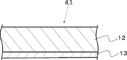
- FIG. 4 is a schematic cross-sectional view showing an example of the resin-coated metal foil used when manufacturing the metal-clad laminate of the present invention.
- the resin-coated metal foil 41 has a structure in which a composition layer 12 made of the composition of the present invention and a metal layer 13 are laminated.
- the resin-coated metal foil 41 may include the composition layer 12 made of the composition before curing and the metal layer 13, and the composition layer 12 made of the semi-cured composition and the metal layer 13 may be provided. may be provided. According to the configuration as described above, it is possible to obtain a resin-coated metal foil from which a metal-clad laminate with sufficiently reduced dielectric loss can be produced.
- Examples of the method of manufacturing the resin-coated metal foil 41 include a method of applying a composition to the surface of the metal foil 13 such as a copper foil and then drying the composition.
- the coating device used for coating can be appropriately selected according to the film thickness of the metal foil to be formed. be done. These may be used individually by 1 type, and may be used 2 or more types.
- the composition or the semi-cured composition may be obtained by drying or heat-drying the composition.
- the conditions for drying or heat drying in the manufacturing method of the resin-coated metal foil 41 are not particularly limited, and it is preferable that the heating temperature is 300 to 400° C. and the heating time is about 5 to 60 minutes.
- the solvent is volatilized, the solvent is reduced or removed, and the resin-coated metal foil 41 in a pre-cured or semi-cured state is obtained.
- a wiring board is manufactured by arranging a wiring circuit on the surface of the metal-clad laminate of the present invention.
- Conventionally known methods can be used as appropriate for the method of forming a wiring circuit on the surface of the metal-clad laminate of the present invention to manufacture a wiring board. can be used, such as a subtractive method of etching the surface or an MSAP method of plating the surface.
- FIG. 5 is a schematic cross-sectional view showing an example of a wiring board manufactured using the metal-clad laminate of the present invention.
- a wiring circuit 16 is formed by etching (partially removed).
- Examples 1 to 9, 11, and 14 to 21 are examples, and Examples 10, 12, and 13 are comparative examples.
- Fluoropolymer A1 EA-2000 (product of AGC Co., Ltd., fluoropolymer containing units based on fluoroolefin and units based on a monomer having an adhesive functional group, melting point 300 ° C. by DSC measurement)
- Fluorine-containing polymer A2 Fluon FL1710 (product of AGC Co., Ltd., polytetrafluoroethylene, a fluoropolymer containing units based on fluoroolefin and not containing units based on a monomer having an adhesive functional group)
- Inorganic filler B1 FB-950XFC (Denka Co., Ltd.
- Inorganic filler B2 FB-25SX (Denka Co., Ltd. product, spherical silica particles, median diameter (average particle diameter D50): 17.3 ⁇ m, specific surface area 3.9 m 2 /g, surface adsorbed water content 483 mass ppm)
- Inorganic filler B3 FB-7SDC (Denka Co., Ltd.
- Inorganic filler B4 FB-304 (Denka Co., Ltd.
- Inorganic filler B5 FB-950FD (product of Denka Co., Ltd., spherical silica particles, median diameter (average particle diameter D50): 24.2 ⁇ m, specific surface area 1.4 m 2 /g, sphericity 0.85 or more, surface adsorbed moisture Amount 173 mass ppm)
- Inorganic filler B6 FB-8C (product of Denka Co., Ltd., spherical silica particles, median diameter (average particle diameter D50): 8.3 ⁇ m, specific surface area 1.6 m 2 /g, sphericity 0.85 or more, surface adsorbed moisture Amount 198 mass ppm)
- Inorganic filler B7 FB-7SDX (Denka Co., Ltd.
- Inorganic filler B8 FB-302X (Denka Co., Ltd. product, spherical silica particles, median diameter (average particle diameter D50): 5.9 ⁇ m, specific surface area 3.5 m 2 /g, surface adsorbed water content 433 mass ppm)
- Inorganic filler B9 FB-105X (Denka Co., Ltd.
- Inorganic filler B10 FB-100XFD (Denka Co., Ltd.
- Inorganic filler B11 FB-950XFD (product of Denka Co., Ltd., spherical silica particles, median diameter (average particle diameter D50): 13.0 ⁇ m, specific surface area 2.0 m 2 /g, surface adsorbed water content 247 mass ppm)
- Examples 1-21 A total of 200 g of each component and 137 g of cyclohexanone described in the component column of the composition in Tables 1 and 2 below were put into a pot, and the mixture was stirred for 20 minutes while applying an acceleration of about 80 G with a low-frequency resonance acoustic mixer (LabMAS II) manufactured by Resodyne. Vibration mixing was carried out to obtain a slurry composition.
- a low-frequency resonance acoustic mixer (LabMAS II) manufactured by Resodyne. Vibration mixing was carried out to obtain a slurry composition.
- the slurry was applied to the surface of a 18 ⁇ m thick copper foil (TQ-M4-VSP, manufactured by Mitsui Mining & Smelting Co., Ltd.) by a doctor blade method to a thickness of 100 ⁇ m, dried for 12 hours in an atmospheric environment at room temperature, and then nitrogen.
- a composition layer was formed by heat drying at 350° C. for 20 minutes in an atmosphere.
- a single-sided metal-clad laminate having a composition layer and a metal layer made of copper foil was obtained. Two of the single-sided metal-clad laminates were stacked with the resin sides facing each other and pressed for 60 minutes at a temperature of 330° C.
- the ratio of the total volume of the polymer and the inorganic filler to the total volume of the composition layer was 100% by volume, and the thickness of the composition layer was 125 ⁇ m.
- the double-sided metal-clad laminate of each example was evaluated as described below. Results are shown in Tables 1 and 2.
- G-CPW grounded coplanar line
- the impedance is 50 ⁇ .
- ⁇ Ten point average roughness Rzjis> The roughened surface of the copper foil was measured using a surfcoder SE600 manufactured by Kosaka Laboratory according to the method specified in Annex JA of JIS B 0601:2013.
- ⁇ Relative permittivity Dk and dielectric loss tangent Df> The dielectric constant Dk and dielectric loss tangent Df of the composition layer (thickness 125 ⁇ m) were measured at 25° C. and 10 GHz according to the method specified in JIS R 1641:2007 using a cavity resonator and a vector network analyzer. In many cases, it is preferable that both the dielectric constant Dk and the dielectric loss tangent Df are small, but depending on the application, it may be better to adjust them to predetermined values.
- thermomechanical analyzer TMA402 FA Hyperion manufactured by NETZSCH
- CTE coefficient of thermal expansion
- the peel strengths of Examples 1-9, 11, 12, and 14-21 are 8.1-19.3 (N/cm), which are all higher than the peel strength of Example 10, 8.0 (N/cm). it was high. Among these, Example 1 (15.5 N/cm), Example 5 (19.3 N/cm), and Example 11 (17.7 N/cm) were particularly high and good.
- the transmission loss for Examples 1-11 and 14-21 was -0.4 dB/cm.
- the transmission loss of Example 12 could not be measured because the composition layer had a high CTE and a transmission line could not be formed.
- the transmission loss of Example 13 could not be measured because the copper foil peeling strength was weak and a transmission path could not be formed.
- the ten-point average roughness of the roughened surface of each of the copper foils of Examples 1 to 21 was 0.6 ⁇ m.
- the dielectric loss tangents Df of Examples 1-12, 15-17, 19 and 21 were all 0.001.
- the dielectric loss tangents Df of Examples 13 and 14 were both 0.0008.
- the dielectric loss tangents Df of Examples 18 and 20 were both 0.0009.
- the dielectric constants Dk of Examples 1 to 14 were all 2.75.
- the dielectric constants Dk of Examples 15-21 were 2.8-2.9.
- a solid By using a composition in which the content of the inorganic filler per minute is 55% by volume or more with respect to the total solid content of the composition, the dielectric constant and dielectric loss tangent are low, and the composition for the metal layer It was found that a metal-clad laminate with improved adhesiveness between layers can be obtained. Further, in the above composition, instead of the fluoropolymer A1 containing units based on fluoroolefin-based units and units based on a monomer having an adhesive functional group, It has been found that when a fluoropolymer containing no units is used, sufficient peel strength cannot be obtained, and transmission loss cannot be measured.
- the present invention has wide industrial applicability in technical fields related to electronic materials and various devices using them.
- Metal-clad laminate 12 Composition layer (insulating layer) 13: Metal layer 14: Adhesive layer (primer layer) 15: Intermediate layer 16: Wiring circuit 41: Metal foil with resin
Landscapes
- Chemical & Material Sciences (AREA)
- Organic Chemistry (AREA)
- Health & Medical Sciences (AREA)
- Chemical Kinetics & Catalysis (AREA)
- Medicinal Chemistry (AREA)
- Polymers & Plastics (AREA)
- Engineering & Computer Science (AREA)
- Microelectronics & Electronic Packaging (AREA)
- Life Sciences & Earth Sciences (AREA)
- Wood Science & Technology (AREA)
- Laminated Bodies (AREA)
- Inorganic Chemistry (AREA)
Abstract
The present invention provides: a composition with which it is possible to obtain a metal-clad laminate that has a low relative permittivity and a low dielectric loss tangent while having improved adhesion of a composition layer to a metal layer; a metal-clad laminate which comprises a composition layer that is composed of this composition; and a method for producing the metal-clad laminate. Provided is a composition which contains a fluorine-containing polymer A1 that contains a unit based on a fluoroolefin and a unit based on a monomer having an adhesive functional group, and an inorganic filler that has a specific surface area of less than 5.5 m2/g, wherein the inorganic filler content in the solid content of the composition is 55 vol% or more relative to the total volume of the solid content of the composition.
Description
本発明は、組成物、並びに、金属張積層体及びその製造方法に関する。
The present invention relates to a composition, a metal-clad laminate, and a method for producing the same.
近年、各種電子機器は、情報処理量の増大に伴い、搭載される半導体デバイスの高集積化、配線の高密度化、及び多層化等の実装技術が急速に進展している。各種電子機器において用いられるプリント配線板の基材を構成するための基板材料には、誘電損失を低減させるために、比誘電率及び誘電正接が低いことが求められる。
In recent years, with the increase in the amount of information processed in various electronic devices, there has been rapid progress in packaging technology such as higher integration of semiconductor devices, higher wiring density, and multilayering. A substrate material for forming a substrate of a printed wiring board used in various electronic devices is required to have a low dielectric constant and a low dielectric loss tangent in order to reduce dielectric loss.
このような要求に対し、銅張積層板(CCL)のコア部分に、樹脂材料の中でも、誘電特性が優れる(すなわち、比誘電率及び誘電正接が低い)フッ素樹脂を含む組成物を使用することが提案されているが、銅張積層板のコア部分にフッ素樹脂を使用する場合、誘電特性は良好であるものの銅箔との接着性が低いという問題があった。
そこで、これらのフッ素樹脂を含む組成物は、銅箔に対する接着性(金属箔ピール強度)を向上させるために、銅箔の表面粗さを大きくしてアンカー効果を得ること(例えば、特許文献1参照)、フッ素樹脂を含む組成物からなる組成物層と銅箔との間に接着層(プライマー層)を設けること(例えば、特許文献2参照)、フッ素樹脂を含む組成物からなる組成物層をプラズマ処理して組成物層表面を活性化すること(例えば、特許文献3参照)、などが行われている。 In response to such demands, a composition containing a fluororesin, which has excellent dielectric properties among resin materials (that is, has a low dielectric constant and a low dielectric loss tangent), is used in the core portion of a copper clad laminate (CCL). However, when a fluororesin is used in the core portion of a copper-clad laminate, although the dielectric properties are good, there is a problem that the adhesiveness to the copper foil is low.
Therefore, in order to improve the adhesiveness (metal foil peel strength) to the copper foil, the composition containing these fluororesins increases the surface roughness of the copper foil to obtain an anchor effect (for example, Patent Document 1 See), providing an adhesive layer (primer layer) between a composition layer made of a composition containing a fluororesin and a copper foil (see, for example, Patent Document 2), a composition layer made of a composition containing a fluororesin are plasma-treated to activate the composition layer surface (see, for example, Patent Document 3).
しかしながら、上記特許文献1では金属張積層体の伝送損失が大きくなることがある。また、上記特許文献2では接着層の誘電損失が大きいことから誘電正接が低減された金属張積層体が得られないことがある。さらに、上記特許文献3では樹脂層がプラズマ処理されることから組成物層材料が脆化することがある。
以上より、比誘電率及び誘電正接が低く、且つ、金属箔に対する樹脂層の接着性が向上した金属張積層体を形成可能な組成物の開発が強く求められている。 However, in Patent Document 1, the transmission loss of the metal-clad laminate may increase. Further, in Patent Document 2, since the dielectric loss of the adhesive layer is large, it may not be possible to obtain a metal-clad laminate with a reduced dielectric loss tangent. Furthermore, in Patent Document 3, since the resin layer is plasma-treated, the composition layer material may become brittle.
As described above, there is a strong demand for the development of a composition capable of forming a metal-clad laminate having a low dielectric constant and a low dielectric loss tangent and having improved adhesiveness of the resin layer to the metal foil.
本発明は、上記問題を鑑み、比誘電率及び誘電正接が低く、且つ、金属層に対する組成物層の接着性が向上した金属張積層体が得られる組成物、並びに、該組成物からなる組成物層を備える金属張積層体及びその製造方法を提供することを課題とする。
In view of the above problems, the present invention provides a composition capable of obtaining a metal-clad laminate having a low dielectric constant and dielectric loss tangent and improved adhesion of the composition layer to the metal layer, and a composition comprising the composition. An object of the present invention is to provide a metal-clad laminate having a material layer and a method for manufacturing the same.
本発明者らは、上記課題を解決するために鋭意検討を行った結果、接着性フッ素樹脂である含フッ素重合体A1と、特定の性質を有する無機フィラーとを特定の割合で混合すると、上記課題を解決し得ることを見出し、本発明を完成させた。
なお、接着性フッ素樹脂である含フッ素重合体A1と、特定の性質を有する無機フィラーとを特定の割合で混合すると、組成物層の金属層に対する接着性が向上する理由としては、金属層に組成物を塗布する場合の粘度が好適となり、金属層/含フッ素重合体A1/無機フィラーにおいて空隙が発生しにくくなるためであると推認される。
すなわち、本発明は下記の通りである。
[1]フルオロオレフィンに基づく単位及び接着性官能基を有するモノマーに基づく単位を含む含フッ素重合体A1と、比表面積が5.5m2/g未満である無機フィラーとを含む組成物であって、
前記組成物の固形分における前記無機フィラーの含有量が、前記組成物の固形分の全体積に対して、55体積%以上である、組成物。
[2]フルオロオレフィンに基づく単位を含み、且つ接着性官能基を有するモノマーに基づく単位を含まない含フッ素重合体A2をさらに含む、[1]に記載の組成物。
[3]前記含フッ素重合体A2の含有量が、前記含フッ素重合体A1と前記含フッ素重合体A2の合計に対して、10体積%以上である、[2]に記載の組成物。
[4]前記接着性官能基が、カルボニル基、ヒドロキシ基、エポキシ基、アミド基、アミノ基及びイソシアネート基からなる群から選ばれる少なくとも1種である、[1]~[3]のいずれかに記載の組成物。
[5]前記無機フィラーは、酸化ケイ素及び酸化チタンの少なくともいずれかである、[1]~[4]のいずれかに記載の組成物。
[6]前記無機フィラーは球形度が0.80以上である、[1]~[5]のいずれかに記載の組成物。
[7]前記無機フィラーのメディアン径(平均粒子径D50)が20μm未満である、[1]~[6]のいずれかに記載の組成物。
[8]前記組成物の固形分における前記無機フィラーの含有量が、前記組成物の固形分の全体積に対して、85体積%以下である、[1]~[7]のいずれかに記載の組成物。
[9]前記無機フィラーの表面吸着水分量が500質量ppm以下である、[1]~[8]のいずれかに記載の組成物。
[10][1]~[9]のいずれかに記載の組成物からなる組成物層と、金属層とを備える、金属張積層体。
[11]前記含フッ素重合体A1を含み、比表面積が5.5m2/g未満の無機フィラーを含まない接着層をさらに備える、[10]に記載の金属張積層体。
[12]前記接着層は、比表面積が5.5m2/g以上である無機フィラーをさらに含み、前記接着層の全体積に対する前記無機フィラーの含有量が、接着層の全体積に対して、85体積%以下である、[11]に記載の金属張積層体。
[13]前記金属層が銅箔からなる層である、[10]~[12]のいずれかに記載の金属張積層体。
[14]前記金属層の前記組成物層側の表面の十点平均粗さ(Rzjis)が2.0μm以下である、[10]~[13]のいずれかに記載の金属張積層体。
[15][1]~[9]のいずれかに記載の組成物を、金属層表面に塗布し、金属張積層体を得る、金属張積層体の製造方法。 The inventors of the present invention have made intensive studies to solve the above problems, and found that when the fluorine-containing polymer A1, which is an adhesive fluororesin, and an inorganic filler having specific properties are mixed in a specific ratio, the above-described The inventors have found that the problem can be solved and completed the present invention.
The reason why the adhesion of the composition layer to the metal layer is improved when the fluoropolymer A1, which is an adhesive fluororesin, and the inorganic filler having a specific property are mixed in a specific ratio is It is presumed that this is because the composition has a suitable viscosity when applied and voids are less likely to occur in the metal layer/fluoropolymer A1/inorganic filler.
That is, the present invention is as follows.
[1] A composition comprising a fluoropolymer A1 containing units based on a fluoroolefin and units based on a monomer having an adhesive functional group, and an inorganic filler having a specific surface area of less than 5.5 m 2 /g ,
The composition, wherein the content of the inorganic filler in the solid content of the composition is 55% by volume or more with respect to the total volume of the solid content of the composition.
[2] The composition of [1], further comprising a fluoropolymer A2 containing units based on a fluoroolefin and not containing units based on a monomer having an adhesive functional group.
[3] The composition according to [2], wherein the content of the fluoropolymer A2 is 10% by volume or more relative to the total of the fluoropolymer A1 and the fluoropolymer A2.
[4] Any one of [1] to [3], wherein the adhesive functional group is at least one selected from the group consisting of a carbonyl group, a hydroxy group, an epoxy group, an amide group, an amino group and an isocyanate group. The described composition.
[5] The composition according to any one of [1] to [4], wherein the inorganic filler is at least one of silicon oxide and titanium oxide.
[6] The composition according to any one of [1] to [5], wherein the inorganic filler has a sphericity of 0.80 or more.
[7] The composition according to any one of [1] to [6], wherein the inorganic filler has a median diameter (average particle diameter D50) of less than 20 μm.
[8] Any one of [1] to [7], wherein the content of the inorganic filler in the solid content of the composition is 85% by volume or less with respect to the total solid content of the composition. composition.
[9] The composition according to any one of [1] to [8], wherein the inorganic filler has a surface adsorbed water content of 500 mass ppm or less.
[10] A metal-clad laminate comprising a composition layer made of the composition according to any one of [1] to [9] and a metal layer.
[11] The metal-clad laminate according to [10], further comprising an adhesive layer containing the fluorine-containing polymer A1 and having a specific surface area of less than 5.5 m 2 /g and containing no inorganic filler.
[12] The adhesive layer further includes an inorganic filler having a specific surface area of 5.5 m 2 /g or more, and the content of the inorganic filler relative to the total volume of the adhesive layer is The metal-clad laminate according to [11], which is 85% by volume or less.
[13] The metal-clad laminate according to any one of [10] to [12], wherein the metal layer is a layer made of copper foil.
[14] The metal-clad laminate according to any one of [10] to [13], wherein the composition layer-side surface of the metal layer has a ten-point average roughness (Rzjis) of 2.0 μm or less.
[15] A method for producing a metal-clad laminate, comprising applying the composition according to any one of [1] to [9] to the surface of the metal layer to obtain a metal-clad laminate.
本発明によれば、比誘電率及び誘電正接が低く、且つ、金属層に対する組成物層の接着性が向上した金属張積層体が得られる組成物、並びに、該組成物からなる組成物層を備える金属張積層体及びその製造方法を提供できる。
According to the present invention, a composition that provides a metal-clad laminate having a low dielectric constant and a low dielectric loss tangent and having improved adhesion of the composition layer to the metal layer, and a composition layer comprising the composition. It is possible to provide a metal-clad laminate and a method for manufacturing the same.
以下、本発明について詳細に説明する。
本明細書において、好ましいとされている規定は任意に採用でき、好ましいもの同士の組み合わせはより好ましいといえる。
本明細書において、「XX~YY」との記載は、「XX以上YY以下」を意味する。
本明細書において、好ましい数値範囲(例えば、含有量等の範囲)について、段階的に記載された下限値及び上限値は、それぞれ独立して組み合わせ得る。例えば、「好ましくは10~90、より好ましくは30~60」という記載から、「好ましい下限値(10)」と「より好ましい上限値(60)」とを組み合わせて、「10~60」とすることもできる。また、本明細書中に記載されている数値範囲において、その数値範囲の上限値又は下限値は、実施例に示されている値に置き換えてもよい。
本明細書において、「モノマーに基づく単位」は、モノマー1分子が重合して直接形成される原子団と、この原子団の一部を化学変換して得られる原子団との総称である。以下、モノマーAに基づく単位をモノマーA単位とも記す。
本明細書において、「接着性官能基を有するモノマーに基づく単位を含まない」とは、「接着性官能基を有するモノマー単位の含有量が、重合体に含まれる全単位に対して0.05モル%未満、好ましくは0.03モル%以下、より好ましくは0.01モル%以下である」ことを意味する。
本明細書において、「組成物の固形分」とは、仮に、組成物が溶媒を含むスラリーである場合、溶媒以外の組成物層を構成する成分を意味する。
本明細書において、「組成物層、接着層、又は中間層」の全体積に対する、重合体A1の含有量(体積%)、重合体A2の含有量(体積%)、及び無機フィラーの含有量(体積%)は、それらを混合(調合)する前に、重合体A1、重合体A2、及び無機フィラーのそれぞれの質量を測定し、それぞれの比重から体積換算して求める。 The present invention will be described in detail below.
In this specification, any definition of preferable can be adopted, and it can be said that a combination of preferable ones is more preferable.
In this specification, the description "XX to YY" means "XX or more and YY or less".
In this specification, for preferred numerical ranges (for example, ranges of contents, etc.), the lower and upper limits described stepwise can be independently combined. For example, from the statement "preferably 10 to 90, more preferably 30 to 60", combining "preferred lower limit (10)" and "more preferred upper limit (60)" to "10 to 60" can also Moreover, in the numerical ranges described in this specification, the upper and lower limits of the numerical ranges may be replaced with the values shown in the examples.
As used herein, "a unit based on a monomer" is a general term for an atomic group directly formed by polymerization of one molecule of a monomer and an atomic group obtained by chemically converting a part of this atomic group. Hereinafter, units based on monomer A are also referred to as monomer A units.
In the present specification, "not containing units based on a monomer having an adhesive functional group" means that "the content of monomer units having an adhesive functional group is 0.05 based on the total units contained in the polymer. less than 0.03 mol%, more preferably 0.01 mol% or less."
As used herein, the term "solid content of the composition" means components constituting the composition layer other than the solvent, if the composition is a slurry containing a solvent.
In this specification, the content of the polymer A1 (% by volume), the content of the polymer A2 (% by volume), and the content of the inorganic filler with respect to the total volume of the "composition layer, adhesive layer, or intermediate layer" (% by volume) is obtained by measuring the mass of each of the polymer A1, the polymer A2, and the inorganic filler before mixing (preparing) them, and converting the respective specific gravities into volume.
(組成物)
本発明の組成物は、含フッ素重合体A1と、無機フィラーとを含み、必要に応じて、含フッ素重合体A2、熱可塑性エラストマー、溶媒、その他の成分をさらに含む。
以下、本発明の組成物の各成分について、具体的に説明する。 (Composition)
The composition of the present invention contains a fluoropolymer A1 and an inorganic filler, and if necessary, further contains a fluoropolymer A2, a thermoplastic elastomer, a solvent and other components.
Each component of the composition of the present invention will be specifically described below.
<含フッ素重合体A1>
含フッ素重合体A1は、フルオロオレフィンに基づく単位及び接着性官能基を有する単位を含み、必要に応じて、フルオロオレフィン及び接着性官能基を有するモノマー以外のその他のモノマーに基づく単位を有していてもよい。 <Fluorine-containing polymer A1>
The fluoropolymer A1 contains units based on a fluoroolefin and units having an adhesive functional group, and if necessary, units based on other monomers other than the fluoroolefin and the monomer having an adhesive functional group. may
<<フルオロオレフィンに基づく単位>>
「フルオロオレフィンに基づく単位」における「フルオロオレフィン」としては、例えば、テトラフルオロエチレン(以下、「TFE」という)、クロロトリフルオロエチレン(以下、「CTFE」という)、トリフルオロエチレン、フッ化ビニル、ビニリデンフルオライド(フッ化ビニリデン(以下、「VdF」という))、ヘキサフルオロプロピレン(以下、HFPという)、CF2=CFORf1(ここで、Rf1は炭素数1~10で炭素原子間に酸素原子を含んでもよいペルフルオロアルキル基)で表されるパーフルオロアルキルビニルエーテル、CF2=CFORf2SO2X1(Rf2は炭素数1~10で炭素原子間に酸素原子を含んでもよいペルフルオロアルキレン基、X1はハロゲン原子又は水酸基)、CF2=CFORf2CO2X2(ここで、Rf2は上記と同様、X2は水素原子又は炭素数1~3のアルキル基)、CF2=CF(CF2)pOCF=CF2(ここで、pは1又は2)、CH2=CX3(CF2)qX4(ここで、X3及びX4は、互いに独立に水素原子又はフッ素原子、qは2~10の整数)、ペルフルオロ(2-メチレン-4-メチル-1,3-ジオキソラン)、などが挙げられる。これらは、1種単独で用いてもよく、2種以上用いてもよい。これらの中でも、誘電正接が低い点で、テトラフルオロエチレン、パーフルオロアルキルビニルエーテルが好ましい。
パーフルオロアルキルビニルエーテルの具体例としては、例えば、CF2=CFOCF2CF3、CF2=CFOCF2CF2CF3、CF2=CFOCF2CF2CF2CF3、CF2=CFO(CF2)8F、などが挙げられる。これらは、1種単独で用いてもよく、2種以上用いてもよい。これらの中でも、CF2=CFOCF2CF2CF3が好ましい。
CH2=CX3(CF2)qX4の具体例としては、例えば、CH2=CH(CF2)2F、CH2=CH(CF2)3F、CH2=CH(CF2)4F、CH2=CF(CF2)3H、CH2=CF(CF2)4H、などが挙げられる。 <<Unit based on fluoroolefin>>
Examples of the "fluoroolefin" in the "fluoroolefin-based unit" include tetrafluoroethylene (hereinafter referred to as "TFE"), chlorotrifluoroethylene (hereinafter referred to as "CTFE"), trifluoroethylene, vinyl fluoride, vinylidene fluoride (vinylidene fluoride (hereinafter referred to as “VdF”)), hexafluoropropylene (hereinafter referred to as HFP), CF 2 =CFOR f1 (here, R f1 has 1 to 10 carbon atoms and oxygen perfluoroalkyl vinyl ether represented by CF 2 ═CFOR f2 SO 2 X 1 (R f2 is a perfluoroalkylene group having 1 to 10 carbon atoms and optionally containing an oxygen atom between carbon atoms) , X 1 is a halogen atom or a hydroxyl group), CF 2 ═CFOR f2 CO 2 X 2 (wherein R f2 is the same as above, and X 2 is a hydrogen atom or an alkyl group having 1 to 3 carbon atoms), CF 2 ═CF (CF 2 ) p OCF=CF 2 (where p is 1 or 2), CH 2 =CX 3 (CF 2 ) q X 4 (wherein X 3 and X 4 are each independently a hydrogen atom or fluorine atom, q is an integer from 2 to 10), perfluoro(2-methylene-4-methyl-1,3-dioxolane), and the like. These may be used individually by 1 type, and may be used 2 or more types. Among these, tetrafluoroethylene and perfluoroalkyl vinyl ether are preferable because of their low dielectric loss tangent.
Specific examples of perfluoroalkyl vinyl ether include CF2 = CFOCF2CF3 , CF2 = CFOCF2CF2CF3 , CF2 = CFOCF2CF2CF2CF3 , CF2 = CFO ( CF2 ) 8 F, and the like. These may be used individually by 1 type, and may be used 2 or more types. Among these, CF 2 =CFOCF 2 CF 2 CF 3 is preferred.
Specific examples of CH2 =CX3 ( CF2)qX4 include , for example, CH2 = CH(CF2) 2F , CH2 = CH( CF2 ) 3F , CH2 =CH( CF2 ) 4F , CH2 =CF(CF2) 3H , CH2 = CF( CF2 ) 4H , and the like.
含フッ素重合体A1におけるフルオロオレフィンに基づく単位の含有量としては、特に制限はないが、含フッ素重合体A1における全単位の合計モル量に対して、好ましくは90.0~99.9モル%、より好ましくは95.0~99.8モル%、特に好ましくは97.0~99.7モル%である。フルオロオレフィンに基づく単位の含有量が上記好ましい範囲にあると、比誘電率及び誘電正接が低い組成物層が得られる。
The content of the fluoroolefin-based units in the fluoropolymer A1 is not particularly limited, but is preferably 90.0 to 99.9 mol% relative to the total molar amount of all units in the fluoropolymer A1. , more preferably 95.0 to 99.8 mol%, particularly preferably 97.0 to 99.7 mol%. When the content of the fluoroolefin-based unit is within the above preferred range, a composition layer having a low dielectric constant and low dielectric loss tangent can be obtained.
<<接着性官能基を有するモノマーに基づく単位>>
「接着性官能基を有するモノマー」における「接着性官能基」としては、例えば、カルボニル基、ヒドロキシ基、エポキシ基、アミド基、アミノ基、イソシアネート基、などが挙げられる。これらは、1種単独で用いてもよく、2種以上用いてもよい。これらの中でも、金属層に対する組成物層の接着性が優れる観点で、カルボニル基が好ましい。 <<Unit based on monomer having adhesive functional group>>
The "adhesive functional group" in the "monomer having an adhesive functional group" includes, for example, a carbonyl group, a hydroxy group, an epoxy group, an amide group, an amino group, an isocyanate group, and the like. These may be used individually by 1 type, and may be used 2 or more types. Among these, a carbonyl group is preferable from the viewpoint of excellent adhesiveness of the composition layer to the metal layer.
「接着性官能基を有するモノマー」としては、例えば、ジカルボン酸無水物基を有し、且つ環内に重合性不飽和基を有する環状炭化水素モノマー(以下、単に、「環状炭化水素モノマー」と略称する)が好適に挙げられる。
上記「環状炭化水素モノマー」は、1つ以上の5員環又は6員環からなる環状炭化水素であって、しかも、ジカルボン酸無水物基と環内重合性不飽和基を有する重合性化合物をいう。環状炭化水素としては、1つ以上の有橋多環炭化水素を有する環状炭化水素が好ましい。すなわち、有橋多環炭化水素からなる環状炭化水素、有橋多環炭化水素の2以上が縮合した環状炭化水素、又は有橋多環炭化水素と他の環状炭化水素が縮合した環状炭化水素であることが好ましい。 Examples of the "monomer having an adhesive functional group" include, for example, a cyclic hydrocarbon monomer having a dicarboxylic anhydride group and a polymerizable unsaturated group in the ring (hereinafter simply referred to as "cyclic hydrocarbon monomer" abbreviated) are preferably mentioned.
The above-mentioned "cyclic hydrocarbon monomer" is a cyclic hydrocarbon consisting of one or more five-membered or six-membered rings, and a polymerizable compound having a dicarboxylic anhydride group and an intracyclic polymerizable unsaturated group. Say. As cyclic hydrocarbons, cyclic hydrocarbons having one or more bridged polycyclic hydrocarbons are preferred. That is, a cyclic hydrocarbon consisting of a bridged polycyclic hydrocarbon, a cyclic hydrocarbon in which two or more bridged polycyclic hydrocarbons are condensed, or a cyclic hydrocarbon in which a bridged polycyclic hydrocarbon and another cyclic hydrocarbon are condensed Preferably.
また、環状炭化水素モノマーは環内重合性不飽和基、すなわち炭化水素環を構成する炭素原子間に存在する重合性不飽和基を1つ以上有する。この環状炭化水素モノマーはさらにジカルボン酸無水物基(-CO-O-CO-)を有し、ジカルボン酸無水物基は炭化水素環を構成する2つの炭素原子に結合していてもよく、環外の2つの炭素原子に結合していてもよい。好ましくは、ジカルボン酸無水物基は上記環状炭化水素の環を構成する炭素原子であって、かつ隣接する2つの炭素原子に結合する。さらに、環状炭化水素の環を構成する炭素原子には、水素原子の代わりに、ハロゲン原子、アルキル基、ハロゲン化アルキル基、その他の置換基が結合していてもよい。
In addition, the cyclic hydrocarbon monomer has one or more endocyclic polymerizable unsaturated groups, that is, one or more polymerizable unsaturated groups present between carbon atoms constituting the hydrocarbon ring. This cyclic hydrocarbon monomer further has a dicarboxylic anhydride group (--CO--O--CO--), and the dicarboxylic anhydride group may be bonded to two carbon atoms constituting a hydrocarbon ring, It may be bonded to two outer carbon atoms. Preferably, the dicarboxylic anhydride group is a carbon atom that constitutes the ring of the cyclic hydrocarbon and is bonded to two adjacent carbon atoms. Furthermore, instead of hydrogen atoms, halogen atoms, alkyl groups, halogenated alkyl groups, and other substituents may be bonded to the carbon atoms that constitute the ring of the cyclic hydrocarbon.
その具体例としては、下記の式(1)~(8)で表されるものである。ここで、式(2)、(5)~(8)におけるRは、炭素原子数1~6の低級アルキル基;フッ素原子、塩素原子、臭素原子、及びヨウ素原子から選択されるハロゲン原子;又は上記低級アルキル基中の水素原子がハロゲン原子で置換されたハロゲン化アルキル基;を示す。
Specific examples are represented by the following formulas (1) to (8). wherein R in formulas (2), (5) to (8) is a lower alkyl group having 1 to 6 carbon atoms; a halogen atom selected from a fluorine atom, a chlorine atom, a bromine atom, and an iodine atom; or A halogenated alkyl group in which a hydrogen atom in the lower alkyl group is substituted with a halogen atom;


上記環状炭化水素モノマーとしては、好ましくは、式(1)で表される、5-ノルボルネン-2,3-ジカルボン酸無水物(以下、「NAH」という);式(3)、(4)で表される酸無水物である環状炭化水素モノマー;式(2)及び式(5)~(8)において、置換基Rがメチル基である環状炭化水素モノマー;であり、より好ましくはNAHである。
The cyclic hydrocarbon monomer is preferably 5-norbornene-2,3-dicarboxylic anhydride (hereinafter referred to as “NAH”) represented by formula (1); a cyclic hydrocarbon monomer that is an acid anhydride represented; a cyclic hydrocarbon monomer in which the substituent R is a methyl group in the formulas (2) and (5) to (8); and more preferably NAH .
含フッ素重合体A1における接着性官能基を有するモノマーに基づく単位の含有量としては、特に制限はないが、含フッ素重合体A1における全単位の合計モル量に対して、好ましくは0.01~5モル%、より好ましくは0.03~3モル%、特に好ましくは0.05~2モル%である。接着性官能基を有するモノマーに基づく単位の含有量が上記好ましい範囲にあると、金属層に対する接着性に優れる組成物層が得られる。
The content of units based on a monomer having an adhesive functional group in the fluoropolymer A1 is not particularly limited, but is preferably 0.01 to 0.01 based on the total molar amount of all units in the fluoropolymer A1. 5 mol %, more preferably 0.03 to 3 mol %, particularly preferably 0.05 to 2 mol %. When the content of units derived from a monomer having an adhesive functional group is within the above preferred range, a composition layer having excellent adhesiveness to a metal layer can be obtained.
<<その他のモノマーに基づく単位>>
その他のモノマーとしては、例えば、エチレン、プロピレン、イソブテン等の炭素数2~4のオレフィン;酢酸ビニル等のビニルエステル;エチルビニルエーテル、シクロヘキシルビニルエーテル等のビニルエーテル;などが挙げられる。これらは、1種単独で用いてもよく、2種以上用いてもよい。 <<units based on other monomers>>
Other monomers include, for example, olefins having 2 to 4 carbon atoms such as ethylene, propylene and isobutene; vinyl esters such as vinyl acetate; vinyl ethers such as ethyl vinyl ether and cyclohexyl vinyl ether; These may be used individually by 1 type, and may be used 2 or more types.
含フッ素重合体A1におけるその他のモノマーに基づく単位の含有量としては、特に制限はないが、含フッ素重合体A1における全単位の合計モル量に対して、好ましくは0.1~10モル%、より好ましくは0.5~5モル%、特に好ましくは1~3モル%である。
The content of the units derived from other monomers in the fluoropolymer A1 is not particularly limited, but is preferably 0.1 to 10 mol% relative to the total molar amount of all units in the fluoropolymer A1. More preferably 0.5 to 5 mol %, particularly preferably 1 to 3 mol %.
含フッ素重合体A1がフルオロオレフィンに基づく単位及び接着性官能基を有するモノマーに基づく単位を含むことによって、金属層に対する組成物層の接着性を向上させることができる。
By including units based on a fluoroolefin and units based on a monomer having an adhesive functional group in the fluoropolymer A1, the adhesiveness of the composition layer to the metal layer can be improved.
含フッ素重合体A1の具体例としては、例えば、TFE/CF2=CFOCF2CF2CF3/NAH共重合体、TFE/HFP/NAH共重合体、TFE/CF2=CFOCF2CF2CF3/HFP/NAH共重合体、TFE/VdF/NAH共重合体、TFE/CH2=CH(CF2)4F/NAH/エチレン共重合体、TFE/CH2=CH(CF2)2F/NAH/エチレン共重合体、CTFE/CH2=CH(CF2)4F/NAH/エチレン共重合体、CTFE/CH2=CH(CF2)2F/NAH/エチレン共重合体、CTFE/CH2=CH(CF2)2F/NAH/エチレン共重合体、などが挙げられる。これらは、1種単独で用いてもよく、2種以上用いてもよい。これらの中でも、製造容易性の観点で、TFE/CF2=CFOCF2CF2CF3/NAH共重合体が好ましい。
Specific examples of the fluoropolymer A1 include, for example, TFE/CF2 = CFOCF2CF2CF3 /NAH copolymer , TFE/HFP/ NAH copolymer , TFE/ CF2 = CFOCF2CF2CF3 /HFP/NAH copolymer, TFE/VdF/NAH copolymer, TFE/ CH2 =CH ( CF2)4F/NAH/ethylene copolymer, TFE/ CH2 =CH ( CF2 ) 2F / NAH/ethylene copolymer, CTFE/ CH2 =CH ( CF2)4F/NAH/ethylene copolymer, CTFE/ CH2 =CH ( CF2 ) 2F /NAH/ethylene copolymer, CTFE/CH 2 =CH ( CF2) 2F /NAH/ethylene copolymer, and the like. These may be used individually by 1 type, and may be used 2 or more types. Among these, the TFE/CF 2 =CFOCF 2 CF 2 CF 3 /NAH copolymer is preferred from the viewpoint of ease of production.
含フッ素重合体A1の融点としては、特に制限はなく、好ましくは150℃以上320℃以下、より好ましくは200℃以上310℃以下である。融点は、フルオロオレフィンに基づく単位、接着性官能基を有するモノマーに基づく単位、及びその他のモノマーに基づく単位の含有割合を適宜選定して調整することができる。
The melting point of the fluoropolymer A1 is not particularly limited, and is preferably 150°C or higher and 320°C or lower, more preferably 200°C or higher and 310°C or lower. The melting point can be adjusted by appropriately selecting the content ratios of units based on fluoroolefin, units based on a monomer having an adhesive functional group, and units based on other monomers.
含フッ素重合体Aの容量流速(以下、Q値という)としては、特に制限はなく、好ましくは5~500mm3/秒、より好ましくは10~200mm3/秒である。Q値は、含フッ素重合体A1の溶融流動性を表す指標であり、分子量の目安となる。Q値が大きい場合には、分子量が低く、小さい場合には、分子量が高いことを示す。
The volumetric flow rate (hereinafter referred to as Q value) of the fluoropolymer A is not particularly limited, and is preferably 5 to 500 mm 3 /sec, more preferably 10 to 200 mm 3 /sec. The Q value is an index representing the melt fluidity of the fluoropolymer A1 and serves as a measure of the molecular weight. A large Q value indicates a low molecular weight, and a small Q value indicates a high molecular weight.
Q値は、島津製作所製フローテスタを用い、含フッ素重合体A1の融点より50℃高い温度において、荷重7kg下に直径2.1mm、長さ8mmのオリフィス中に押し出すときの含フッ素重合体A1の押出速度である。このQ値が小さすぎると、成形が困難となり、逆に大きすぎると、含フッ素重合体A1の機械的強度が低下する。
The Q value is obtained by using a flow tester manufactured by Shimadzu Corporation and extruding the fluoropolymer A1 through an orifice having a diameter of 2.1 mm and a length of 8 mm under a load of 7 kg at a temperature 50°C higher than the melting point of the fluoropolymer A1. is the extrusion speed. If the Q value is too small, molding becomes difficult, and if it is too large, the mechanical strength of the fluoropolymer A1 decreases.
含フッ素重合体A1の製造方法は、特に制限はなく、公知の方法で製造できる。
The method for producing the fluoropolymer A1 is not particularly limited, and it can be produced by a known method.
公知の製造方法で得られた含フッ素重合体A1は、定法に従い、ペレット、粉体、その他の形態として得ることができる。この含フッ素重合体A1は、成形性に優れるため、射出成形、押出成形、プレス成形などが可能であり、所望の形状に成形することができる。
The fluoropolymer A1 obtained by a known production method can be obtained in the form of pellets, powder, and other forms according to standard methods. Since the fluoropolymer A1 has excellent moldability, it can be molded into a desired shape by injection molding, extrusion molding, press molding, or the like.
含フッ素重合体A1は、上記のようにして製造することもできるが、市販品を用いることもできる。含フッ素重合体A1の市販品としては、特に制限はないが、例えば、AGC株式会社製のEA-2000、などが挙げられる。
The fluoropolymer A1 can be produced as described above, but a commercially available product can also be used. Commercial products of the fluoropolymer A1 are not particularly limited, and examples thereof include EA-2000 manufactured by AGC Corporation.
本発明の組成物の固形分における含フッ素重合体A1の含有量としては、組成物の固形分の全体積に対して、45体積%以下である限り、特に制限はないが、熱膨張係数や機械強度の観点から、好ましくは15~45体積%、より好ましくは20~40体積%、特に好ましくは30~40体積%である。
本発明の組成物の固形分における含フッ素重合体A1の含有量が、上記好ましい範囲内であると、基板の強度を損なうことなく、金属層に対する組成物層の接着性を向上させることができる。 The content of the fluoropolymer A1 in the solid content of the composition of the present invention is not particularly limited as long as it is 45% by volume or less with respect to the total solid content of the composition. From the viewpoint of mechanical strength, it is preferably 15 to 45% by volume, more preferably 20 to 40% by volume, and particularly preferably 30 to 40% by volume.
When the content of the fluoropolymer A1 in the solid content of the composition of the present invention is within the above preferable range, the adhesiveness of the composition layer to the metal layer can be improved without impairing the strength of the substrate. .
<無機フィラー>
無機フィラーとしては、例えば、球状シリカ等の酸化ケイ素;酸化チタン、アルミナ、マイカ等の金属酸化物;水酸化アルミニウム、水酸化マグネシウム等の金属水酸化物;タルク;ホウ酸アルミニウム;硫酸バリウム;炭酸カルシウム;などが挙げられる。 <Inorganic filler>
Examples of inorganic fillers include silicon oxides such as spherical silica; metal oxides such as titanium oxide, alumina and mica; metal hydroxides such as aluminum hydroxide and magnesium hydroxide; talc; aluminum borate; barium sulfate; calcium; and the like.
無機フィラーは、ガラス微小球、セラミック微小球等の中空無機微小球であってもよい。
ガラス微小球は、シリカガラス又はボロシリケートガラスを含むものが好ましい。
セラミック微小球は、チタン酸バリウムを含むものが好ましく、ネオジウム又は酸化亜鉛がドープされたチタン酸バリウムを含むものが特に好ましい。
中空無機微小球は、非多孔質であってもよく、多孔質であってもよく、また、結晶性であってもよく、非結晶性であってもよい。
中空無機微小球は、フエニルトリメトキシシラン、フェニルトリエトキシシラン、(3,3,3-トリフルオロプロピル)トリメトキシシラン、(トリデカフルオロ-1,1,2,2-テトラヒドロオクチル)-1,1-トリエトキシシラン、(ヘプタデカフルオロ-1,1,2,2-テトラヒドロデシル)-1-トリエトキシシラン等のシランカップリング剤;ネオペンチル(ジアリル)オキシトリ(ジオクチル)ピロフォスフェートジルコネート、ネオペンチル(ジアリル)オキシトリ(N-エチレンジアミノ)エチルジルコネート等のジルコネート;ネオペンチル(ジアリル)オキシトリネオデカノイルチタネート、ネオペンチル(ジアリル)オキシトリ(ドデシル)ベンゼン-スルホニルチタネート、ネオペンチル(ジアリル)オキシトリ(ジオクチル)ホスフェートチタネート等のチタネート類;などによって被覆処理されて疎水性であることが好ましい。
これらは、1種単独で用いてもよく、2種以上用いてもよい。これらの中でも、低熱膨張性の観点で、酸化ケイ素、酸化チタンが好ましく、球状シリカがより好ましい。 The inorganic filler may be hollow inorganic microspheres such as glass microspheres, ceramic microspheres and the like.
The glass microspheres preferably comprise silica glass or borosilicate glass.
Preferably, the ceramic microspheres comprise barium titanate, particularly barium titanate doped with neodymium or zinc oxide.
Hollow inorganic microspheres may be non-porous or porous, crystalline or non-crystalline.
Hollow inorganic microspheres include phenyltrimethoxysilane, phenyltriethoxysilane, (3,3,3-trifluoropropyl)trimethoxysilane, (tridecafluoro-1,1,2,2-tetrahydrooctyl)-1 , 1-triethoxysilane, (heptadecafluoro-1,1,2,2-tetrahydrodecyl)-1-triethoxysilane and other silane coupling agents; neopentyl(diallyl)oxytri(dioctyl)pyrophosphate zirconate, zirconates such as neopentyl(diallyl)oxytri(N-ethylenediamino)ethylzirconate; neopentyl(diallyl)oxytri-neodecanoyl titanate, neopentyl(diallyl)oxytri(dodecyl)benzene-sulfonyl titanate, neopentyl(diallyl)oxytri(dioctyl) It is preferably coated with titanates such as phosphate titanate to make it hydrophobic.
These may be used individually by 1 type, and may be used 2 or more types. Among these, from the viewpoint of low thermal expansion properties, silicon oxide and titanium oxide are preferred, and spherical silica is more preferred.
無機フィラーの比表面積としては、5.5m2/g未満である限り、特に制限はないが、好ましくは4.5m2/g未満、より好ましくは3.5m2/g未満、特に好ましくは3.0m2/g未満である。
無機フィラーの比表面積が、上記好ましい範囲内であると、金属層に対する組成物層の接着性が十分となる。
なお、ここでの「比表面積」は、実施例と同様の方法で測定される。 The specific surface area of the inorganic filler is not particularly limited as long as it is less than 5.5 m 2 /g, preferably less than 4.5 m 2 /g, more preferably less than 3.5 m 2 /g, particularly preferably 3 less than .0 m 2 /g.
When the specific surface area of the inorganic filler is within the preferred range, the composition layer has sufficient adhesiveness to the metal layer.
In addition, the "specific surface area" here is measured by the same method as in the examples.
無機フィラーの球形度としては、特に制限はないが、好ましくは0.80以上、より好ましくは0.83以上、特に好ましくは0.85以上である。
無機フィラーの球形度が、上記好ましい範囲内であると、スルーホールめっき品質を向上させることができる。
なお、ここでの「球形度」は、実施例と同様の方法で測定される。 The sphericity of the inorganic filler is not particularly limited, but is preferably 0.80 or more, more preferably 0.83 or more, and particularly preferably 0.85 or more.
When the sphericity of the inorganic filler is within the above preferable range, through-hole plating quality can be improved.
The "sphericity" here is measured by the same method as in the examples.
無機フィラーのメディアン径(平均粒子径D50)としては、特に制限はないが、好ましくは20μm未満、より好ましくは15μm未満、特に好ましくは10μm未満である。
無機フィラーのメディアン径(平均粒子径D50)が、上記好ましい範囲内であると、組成物層の均質性やドリル加工性に優れる。
なお、ここでの「メディアン径(平均粒子径D50)」は、実施例と同様の方法で測定される。 The median diameter (average particle diameter D50) of the inorganic filler is not particularly limited, but is preferably less than 20 µm, more preferably less than 15 µm, and particularly preferably less than 10 µm.
When the median diameter (average particle diameter D50) of the inorganic filler is within the above preferred range, the composition layer is excellent in homogeneity and drillability.
The "median diameter (average particle diameter D50)" here is measured by the same method as in the examples.
無機フィラーの表面吸着水分量としては、特に制限はないが、好ましくは500質量ppm以下、より好ましくは400質量ppm以下、特に好ましくは300質量ppm以下である。
無機フィラーの表面吸着水分量が、上記好ましい範囲内であると、組成物層の誘電正接を低くすることができる。
なお、ここでの「表面吸着水分量」は、実施例と同様の方法で測定される。 The amount of water adsorbed on the surface of the inorganic filler is not particularly limited, but is preferably 500 mass ppm or less, more preferably 400 mass ppm or less, and particularly preferably 300 mass ppm or less.
When the amount of water adsorbed on the surface of the inorganic filler is within the above preferred range, the dielectric loss tangent of the composition layer can be reduced.
The "surface adsorbed water content" is measured in the same manner as in the examples.
組成物の固形分における無機フィラーの含有量としては、組成物の固形分の全体積に対して、55体積%以上である限り、特に制限はないが、組成物層の熱膨張係数を抑制するという観点から、好ましくは63体積%以上、より好ましくは65体積%以上である。無機フィラーの含有量を増やすことにより組成物層の剛性や後述する熱膨張係数CTEをより小さくすることが出来るため好ましい。
また、組成物の固形分における無機フィラーの含有量の上限値としては、特に制限はないが、組成物層の熱膨張係数を抑制するという観点から、好ましくは85体積%以下、より好ましくは75体積%以下、特に好ましくは73体積%以下である。 The content of the inorganic filler in the solid content of the composition is not particularly limited as long as it is 55% by volume or more with respect to the total solid content of the composition, but the thermal expansion coefficient of the composition layer is suppressed. From this point of view, the content is preferably 63% by volume or more, more preferably 65% by volume or more. By increasing the content of the inorganic filler, the rigidity of the composition layer and the coefficient of thermal expansion CTE, which will be described later, can be made smaller, which is preferable.
In addition, the upper limit of the content of the inorganic filler in the solid content of the composition is not particularly limited, but from the viewpoint of suppressing the thermal expansion coefficient of the composition layer, it is preferably 85% by volume or less, more preferably 75% by volume. % by volume or less, particularly preferably 73% by volume or less.
<含フッ素重合体A2>
任意成分である含フッ素重合体A2は、フルオロオレフィンに基づく単位を含み、且つ接着性官能基を有するモノマーに基づく単位を含まず、フルオロオレフィン及び接着性官能基を有するモノマー以外のその他のモノマーに基づく単位を含んでいてもよい。
なお、「フルオロオレフィンに基づく単位」、「接着性官能基を有するモノマーに基づく単位」、及び「その他のモノマーに基づく単位」は、「含フッ素重合体A1」の欄で説明した通りである。
含フッ素重合体A2におけるフルオロオレフィンに基づく単位の含有量としては、特に制限はないが、含フッ素重合体A2における全単位の合計モル量に対して、好ましくは90~100モル%、より好ましくは95~100モル%、特に好ましくは97~100モル%である。フルオロオレフィンに基づく単位の含有量が上記好ましい範囲にあると、比誘電率及び誘電正接が低い組成物層が得られる。
含フッ素重合体A2におけるその他のモノマーに基づく単位の含有量としては、特に制限はないが、含フッ素重合体A2における全単位の合計モル量に対して、好ましくは0~10モル%、より好ましくは0~5モル%、特に好ましくは0~3モル%である。
含フッ素重合体A2がフルオロオレフィンに基づく単位を含み、且つ接着性官能基を有するモノマーに基づく単位を含まないことによって、組成物層の誘電正接を低くすることができる。 <Fluorine-containing polymer A2>
The optional fluoropolymer A2 contains units based on a fluoroolefin and does not contain units based on a monomer having an adhesive functional group, and contains other monomers other than the fluoroolefin and the monomer having an adhesive functional group. May contain units based on.
The "fluoroolefin-based unit", the "monomer-based unit having an adhesive functional group", and the "other monomer-based unit" are as described in the "fluoropolymer A1" section.
The content of the fluoroolefin-based units in the fluoropolymer A2 is not particularly limited, but is preferably 90 to 100 mol%, more preferably 90 to 100 mol%, based on the total molar amount of all units in the fluoropolymer A2. 95 to 100 mol %, particularly preferably 97 to 100 mol %. When the content of the fluoroolefin-based unit is within the above preferred range, a composition layer having a low dielectric constant and low dielectric loss tangent can be obtained.
The content of units derived from other monomers in the fluoropolymer A2 is not particularly limited, but is preferably 0 to 10 mol%, more preferably 0 to 10 mol%, based on the total molar amount of all units in the fluoropolymer A2. is 0 to 5 mol %, particularly preferably 0 to 3 mol %.
When the fluoropolymer A2 contains units based on fluoroolefin and does not contain units based on a monomer having an adhesive functional group, the dielectric loss tangent of the composition layer can be lowered.
含フッ素重合体A2は、市販品を用いることもできる。含フッ素重合体A2の市販品としては、特に制限はないが、例えば、AGC株式会社製のFluon FL1710、などが挙げられる。
A commercially available product can also be used as the fluoropolymer A2. Commercially available products of the fluoropolymer A2 are not particularly limited, but examples thereof include Fluon FL1710 manufactured by AGC Corporation.
含フッ素重合体A2を含む場合、含フッ素重合体A2の含有量としては、特に制限はないが、含フッ素重合体A1と含フッ素重合体A2の合計に対して、好ましくは10体積%以上、より好ましくは20~80体積%、特に好ましくは40~70体積%である。
含フッ素重合体A2の含有量が、上記好ましい範囲内であると、フッ素単位が多くなるので、誘電正接をさらに向上させることができる。 When the fluoropolymer A2 is included, the content of the fluoropolymer A2 is not particularly limited. More preferably 20 to 80% by volume, particularly preferably 40 to 70% by volume.
When the content of the fluoropolymer A2 is within the above preferred range, the fluorine units are increased, so that the dielectric loss tangent can be further improved.
<溶媒>
任意成分である溶媒としては、例えば、トルエン、キシレン、メチルエチルケトン、メチルイソブチルケトン、シクロヘキサノン、酢酸エチル、酢酸ブチル、ジメチルホルムアミド、ジメチルアセトアミド、N-メチルピロリドンなどが挙げられる。これらは、1種単独で用いてもよく、2種以上用いてもよい。これらの中でも、組成物の溶解性及び取扱い性の観点で、トルエン、メチルエチルケトン、N-メチルピロリドン、シクロヘキサノンが好ましい。 <Solvent>
Examples of optional solvents include toluene, xylene, methyl ethyl ketone, methyl isobutyl ketone, cyclohexanone, ethyl acetate, butyl acetate, dimethylformamide, dimethylacetamide, and N-methylpyrrolidone. These may be used individually by 1 type, and may be used 2 or more types. Among these, toluene, methyl ethyl ketone, N-methylpyrrolidone, and cyclohexanone are preferred from the viewpoint of the solubility and handleability of the composition.
本発明の組成物が溶媒を含有する場合は、本発明の組成物中における溶媒の含有量としては、特に制限はないが、100質量部の含フッ素重合体A1に対して、好ましくは50~400質量部、より好ましくは100~300質量部、特に好ましくは150~250質量部である。
溶媒の含有量が、上記下限値以上であると、組成物の取扱い性が良好になり、また、上記上限値以下であると、所定の厚みの組成物層が得られる。 When the composition of the present invention contains a solvent, the content of the solvent in the composition of the present invention is not particularly limited. 400 parts by mass, more preferably 100 to 300 parts by mass, particularly preferably 150 to 250 parts by mass.
When the content of the solvent is at least the above lower limit value, the composition is easy to handle, and when it is at most the above upper limit value, a composition layer having a predetermined thickness can be obtained.
<その他の成分>
任意成分であるその他の成分としては、例えば、界面活性剤;シリコーン系消泡剤、アクリル酸エステル系消泡剤等の消泡剤;熱安定剤;帯電防止剤;紫外線吸収剤;染料;顔料;滑剤;湿潤分散剤等の分散剤;などが挙げられる。これらは、1種単独で用いてもよく、2種以上用いてもよい。これらの中でも、機械特性の観点で、界面活性剤が好ましい。 <Other ingredients>
Other optional components include, for example, surfactants; antifoaming agents such as silicone antifoaming agents and acrylate ester antifoaming agents; heat stabilizers; antistatic agents; ultraviolet absorbers; dyes; a lubricant; a dispersant such as a wetting and dispersing agent; These may be used individually by 1 type, and may be used 2 or more types. Among these, surfactants are preferable from the viewpoint of mechanical properties.
<<界面活性剤>>
界面活性剤としては、例えば、ノニオン性のフッ素系界面活性剤、シリコーン系界面活性剤、炭化水素系界面活性剤などが挙げられる。これらは、1種単独で用いてもよく、2種以上用いてもよい。これらの中でも、含フッ素重合体A1の分散性の観点で、ノニオン性のフッ素系界面活性剤が好ましい。 <<Surfactant>>
Examples of surfactants include nonionic fluorine-based surfactants, silicone-based surfactants, and hydrocarbon-based surfactants. These may be used individually by 1 type, and may be used 2 or more types. Among these, nonionic fluorine-based surfactants are preferred from the viewpoint of dispersibility of the fluoropolymer A1.
本発明の組成物が界面活性剤を含有する場合は、界面活性剤の含有量としては、特に制限はなく、100質量部の含フッ素重合体A1に対して、好ましくは5~30質量部、より好ましくは10~20質量部である。
When the composition of the present invention contains a surfactant, the content of the surfactant is not particularly limited. More preferably 10 to 20 parts by mass.
なお、本発明の組成物は、例えば、組成物を330~380℃で5~60分間加熱することにより硬化して、後述する組成物層となる。
The composition of the present invention is cured, for example, by heating the composition at 330 to 380° C. for 5 to 60 minutes to form a composition layer to be described later.
(金属張積層体)
本発明の金属張積層体は、本発明の組成物からなる組成物層と、金属層とを備え、必要に応じて、接着層、中間層をさらに備える。 (Metal clad laminate)
The metal-clad laminate of the present invention comprises a composition layer made of the composition of the present invention, a metal layer, and, if necessary, an adhesive layer and an intermediate layer.
本発明の金属張積層体は、本発明の組成物からなる組成物層と、金属層とを備え、必要に応じて、接着層、中間層をさらに備える。 (Metal clad laminate)
The metal-clad laminate of the present invention comprises a composition layer made of the composition of the present invention, a metal layer, and, if necessary, an adhesive layer and an intermediate layer.
図1は、本発明の金属張積層体の一例を示す概略断面図である。
図1に示すように、金属張積層体11は、本発明の組成物からなる組成物層(絶縁層)12と、組成物層(絶縁層)12の両面に配置された金属層13とを有する。
なお、本発明の金属張積層体は、図1に示すように、組成物層12の両面に金属層13が配置された両面金属箔張りの積層板であってもよく、また、組成物層12の片面に金属層13が配置された片面金属箔張りの積層板であってもよい(後述する図4参照)。さらに、本発明の金属張積層体は、金属層13及び組成物層12で構成される積層構造を多数積層した構造を有していてもよい。なお、金属層13として銅箔を使用した片面金属箔張りの積層板を樹脂付き銅箔(Resin Coated Copper Foil:RCC)と呼び、金属層13として銅箔を使用した両面金属箔張りの積層板を銅張積層板(Copper Clad Laminate:CCL)と呼ぶ。 FIG. 1 is a schematic cross-sectional view showing an example of the metal-clad laminate of the present invention.
As shown in FIG. 1, the metal-cladlaminate 11 comprises a composition layer (insulating layer) 12 made of the composition of the present invention and metal layers 13 disposed on both sides of the composition layer (insulating layer) 12. have.
As shown in FIG. 1, the metal-clad laminate of the present invention may be a double-sided metal foil-clad laminate in which metal layers 13 are arranged on both sides of acomposition layer 12. A single-sided metal foil-clad laminated plate having a metal layer 13 disposed on one side of 12 may also be used (see FIG. 4 described later). Furthermore, the metal-clad laminate of the present invention may have a structure in which a number of laminated structures composed of the metal layers 13 and the composition layers 12 are laminated. A single-sided metal-foiled laminate using copper foil as the metal layer 13 is called a resin-coated copper foil (RCC), and a double-sided metal-foiled laminate using copper foil as the metal layer 13. is called a copper clad laminate (CCL).
図1に示すように、金属張積層体11は、本発明の組成物からなる組成物層(絶縁層)12と、組成物層(絶縁層)12の両面に配置された金属層13とを有する。
なお、本発明の金属張積層体は、図1に示すように、組成物層12の両面に金属層13が配置された両面金属箔張りの積層板であってもよく、また、組成物層12の片面に金属層13が配置された片面金属箔張りの積層板であってもよい(後述する図4参照)。さらに、本発明の金属張積層体は、金属層13及び組成物層12で構成される積層構造を多数積層した構造を有していてもよい。なお、金属層13として銅箔を使用した片面金属箔張りの積層板を樹脂付き銅箔(Resin Coated Copper Foil:RCC)と呼び、金属層13として銅箔を使用した両面金属箔張りの積層板を銅張積層板(Copper Clad Laminate:CCL)と呼ぶ。 FIG. 1 is a schematic cross-sectional view showing an example of the metal-clad laminate of the present invention.
As shown in FIG. 1, the metal-clad
As shown in FIG. 1, the metal-clad laminate of the present invention may be a double-sided metal foil-clad laminate in which metal layers 13 are arranged on both sides of a
本発明の金属張積層体において、組成物層の熱膨張係数CTEが10~25ppm/℃であることが好ましい。
なお、熱膨張係数CTE(ppm/℃)は、評価用サンプル(組成物層)について、熱機械分析装置(NETZSCH社製のTMA402FA Hyperion)を用いて、ガラス転移温度未満における熱膨張係数CTEを測定した。なお、ガラス転移温度未満における熱膨張係数CTEは、昇温速度5℃/min、-20℃~240℃の範囲で行った。 In the metal-clad laminate of the present invention, the thermal expansion coefficient CTE of the composition layer is preferably 10-25 ppm/°C.
The coefficient of thermal expansion CTE (ppm/° C.) is obtained by measuring the coefficient of thermal expansion CTE below the glass transition temperature of the evaluation sample (composition layer) using a thermomechanical analyzer (TMA402FA Hyperion manufactured by NETZSCH). did. The coefficient of thermal expansion CTE below the glass transition temperature was measured at a heating rate of 5°C/min in the range of -20°C to 240°C.
上述のような構成によれば、誘電損失が十分に低減された基板を作製可能な金属張積層体が得られる。
According to the configuration as described above, a metal-clad laminate is obtained that allows a substrate with sufficiently reduced dielectric loss to be produced.
図2は、本発明の金属張積層体の他の一例を示す概略断面図である。
図2に示すように、金属張積層体21は、本発明の組成物からなる組成物層12と、組成物層12の両表面外側に配置された金属層13と、組成物層12及び金属層13の間に配置された接着層(プライマー層)14とを有する。すなわち、金属張積層体21は、金属層13と、接着層14と、組成物層12とをこの順に有し、接着層14は、金属層13の表面上に設けられ、組成物層12は、接着層14の表面上に設けられる。 FIG. 2 is a schematic cross-sectional view showing another example of the metal-clad laminate of the present invention.
As shown in FIG. 2, the metal cladlaminate 21 includes a composition layer 12 made of the composition of the present invention, a metal layer 13 disposed on both outer surfaces of the composition layer 12, a composition layer 12 and a metal layer. and an adhesive layer (primer layer) 14 disposed between the layers 13 . That is, the metal-clad laminate 21 has a metal layer 13, an adhesive layer 14, and a composition layer 12 in this order, the adhesive layer 14 being provided on the surface of the metal layer 13, and the composition layer 12 being , is provided on the surface of the adhesive layer 14 .
図2に示すように、金属張積層体21は、本発明の組成物からなる組成物層12と、組成物層12の両表面外側に配置された金属層13と、組成物層12及び金属層13の間に配置された接着層(プライマー層)14とを有する。すなわち、金属張積層体21は、金属層13と、接着層14と、組成物層12とをこの順に有し、接着層14は、金属層13の表面上に設けられ、組成物層12は、接着層14の表面上に設けられる。 FIG. 2 is a schematic cross-sectional view showing another example of the metal-clad laminate of the present invention.
As shown in FIG. 2, the metal clad
図3は、本発明の金属張積層体のさらに他の一例を示す概略断面図である。
図3に示すように、金属張積層体31は、組成物層12を2つに分割する中間層15をさらに備えること以外は、図2の金属張積層体21と同様である。 FIG. 3 is a schematic cross-sectional view showing still another example of the metal-clad laminate of the present invention.
As shown in FIG. 3, the metal-cladlaminate 31 is similar to the metal-clad laminate 21 of FIG. 2 except that it further includes an intermediate layer 15 that divides the composition layer 12 into two.
図3に示すように、金属張積層体31は、組成物層12を2つに分割する中間層15をさらに備えること以外は、図2の金属張積層体21と同様である。 FIG. 3 is a schematic cross-sectional view showing still another example of the metal-clad laminate of the present invention.
As shown in FIG. 3, the metal-clad
<組成物層>
組成物層は、本発明の組成物からなる層である。
組成物層の厚みは、特に制限はないが、変形や折れ曲がりによる回路配線の断線を予防する観点から、好ましくは50μm以上、より好ましくは70μm以上、特に好ましくは100μm以上である。
また、組成物層の厚みは、特に制限はないが、作製する配線基板の柔軟性、小型化及び軽量化の観点から、好ましくは300μm以下、より好ましくは200μm以下、特に好ましくは150μm以下である。 <Composition layer>
A composition layer is a layer which consists of the composition of this invention.
The thickness of the composition layer is not particularly limited, but is preferably 50 µm or more, more preferably 70 µm or more, and particularly preferably 100 µm or more from the viewpoint of preventing disconnection of circuit wiring due to deformation or bending.
The thickness of the composition layer is not particularly limited, but is preferably 300 μm or less, more preferably 200 μm or less, and particularly preferably 150 μm or less from the viewpoint of flexibility, size reduction, and weight reduction of the wiring board to be produced. .
また、周波数10GHzにおける組成物層の誘電正接Dfとしては、伝送損失を抑制する観点から、好ましくは0.0020以下、より好ましくは0.0015以下、特に好ましくは0.0010以下である。
なお、ここでの「誘電正接Df」は、実施例と同様の方法で測定される。 From the viewpoint of suppressing transmission loss, the dielectric loss tangent Df of the composition layer at a frequency of 10 GHz is preferably 0.0020 or less, more preferably 0.0015 or less, and particularly preferably 0.0010 or less.
The "dielectric loss tangent Df" here is measured by the same method as in the examples.
周波数10GHzにおける組成物層の比誘電率Dkとしては、作製容易性及び選択肢を広げる観点から、好ましくは2.0以上、より好ましくは2.2以上、特に好ましくは2.4以上である。
また、周波数10GHzにおける組成物層の比誘電率Dkとしては、伝送損失を抑制する観点から、好ましくは4.0以下、より好ましくは3.5以下、特に好ましくは3.2以下である。
なお、ここでの「比誘電率Dk」は、実施例と同様の方法で測定される。 The dielectric constant Dk of the composition layer at a frequency of 10 GHz is preferably 2.0 or higher, more preferably 2.2 or higher, and particularly preferably 2.4 or higher, from the viewpoint of ease of production and widening options.
Further, the dielectric constant Dk of the composition layer at a frequency of 10 GHz is preferably 4.0 or less, more preferably 3.5 or less, particularly preferably 3.2 or less, from the viewpoint of suppressing transmission loss.
The "relative permittivity Dk" here is measured by the same method as in the examples.
<金属層>
金属層としては、例えば、電気抵抗が低い、銅箔、銀箔、金箔及びアルミニウム箔等の導電性金属箔を用いることができ、銅箔を用いることが好ましい。
金属層は、1種の金属を単独で使用し、1種の金属から構成されてもよいし、複数種の金属を併用し、複数種の金属から構成されてもよい。複数種の金属の併用方法としては、金属箔に金属メッキを施す方法を用いることができ、例えば、金属箔として、金メッキを施した銅箔を用いることができる。
また、金属層の厚みに応じて、ハンドリング性向上のために、剥離層及びキャリアを備えたキャリア付き金属箔を用いてもよい。さらに、金属層は、電解製箔又は圧延製箔されたままの金属箔(生箔)であってもよいし、一方の面又は両面に表面処理が施されていてもよい。前記表面処理としては、例えば、防錆処理、シラン処理、粗面化処理、バリア形成処理を挙げることができる。 <Metal layer>
As the metal layer, for example, a conductive metal foil such as a copper foil, a silver foil, a gold foil and an aluminum foil having a low electric resistance can be used, and a copper foil is preferably used.
The metal layer may be composed of one kind of metal by using one kind of metal alone, or may be composed of two or more kinds of metals by using two or more kinds of metals together. As a method for using a plurality of kinds of metals in combination, a method of plating a metal foil with a metal can be used. For example, a gold-plated copper foil can be used as the metal foil.
Further, depending on the thickness of the metal layer, a carrier-attached metal foil having a peeling layer and a carrier may be used to improve handling. Furthermore, the metal layer may be a metal foil (raw foil) as it has been electrolytically manufactured or rolled, or may be surface-treated on one side or both sides. Examples of the surface treatment include rust prevention treatment, silane treatment, surface roughening treatment, and barrier formation treatment.
金属層として用いられる金属箔の市販品としては、例えば、TQ-M4-VSP(商品名、三井金属鉱業株式会社製、銅箔、Rzjis:0.6μm、厚み:18μm)を使用できる。
As a commercial product of the metal foil used as the metal layer, for example, TQ-M4-VSP (trade name, manufactured by Mitsui Kinzoku Mining Co., Ltd., copper foil, Rzjis: 0.6 μm, thickness: 18 μm) can be used.
金属層の厚みとしては、特に限定はないが、好ましくは0.1~100μm、より好ましくは0.2~50μm、特に好ましくは1.0~30μmである。金属層の厚みが、上記好ましい範囲内であれば、配線基板の通常の配線パターン形成方法、例えば、MSAP(モディファイド・セミアディティブ)法及びサブトラクティブ法等を容易に採用できる。
Although the thickness of the metal layer is not particularly limited, it is preferably 0.1 to 100 μm, more preferably 0.2 to 50 μm, and particularly preferably 1.0 to 30 μm. As long as the thickness of the metal layer is within the above preferable range, it is possible to easily adopt a normal wiring pattern forming method for wiring substrates, such as the MSAP (modified semi-additive) method and the subtractive method.
金属層の組成物層側の面の十点平均粗さ(Rzjis)としては、特に制限はないが、好ましくは2.0μm以下、より好ましくは1.0μm以下、特に好ましくは0.8μm以下である。これらの上限値は、高周波領域での使用時の金属箔の表皮効果によって増大し得る金属層に起因する導体損失を低減させて、伝送損失を低減させる観点から好ましい。なお、表皮効果とは、高周波電気信号が、金属層の表面近傍にしか流れない現象を意味する。表皮効果によって、金属層表面の凹凸に追従して電気信号が流れるため、粗度が粗い金属層ほど電気信号の伝達距離が増えて導体損失が悪化する場合がある。
金属箔の組成物層側の面の十点平均粗さ(Rzjis)としては、特に制限はないが、好ましくは0.10μm以上、より好ましくは0.15μm以上、特に好ましくは0.20μm以上である。これらの下限値は、金属層と組成物層又は後述する接着層との密着性を向上させる観点から好ましい。
なお、ここでの「十点平均粗さ(Rzjis)」は、実施例と同様の方法で測定される。 The ten-point average roughness (Rzjis) of the surface of the metal layer on the composition layer side is not particularly limited, but is preferably 2.0 μm or less, more preferably 1.0 μm or less, and particularly preferably 0.8 μm or less. be. These upper limits are preferable from the viewpoint of reducing transmission loss by reducing conductor loss caused by the metal layer, which may increase due to the skin effect of the metal foil during use in a high frequency region. Note that the skin effect means a phenomenon in which a high-frequency electric signal flows only near the surface of a metal layer. Due to the skin effect, electrical signals flow following the irregularities on the surface of the metal layer. Therefore, the more rough the metal layer, the longer the electrical signal transmission distance, and the worse the conductor loss.
The ten-point average roughness (Rzjis) of the surface of the metal foil on the composition layer side is not particularly limited, but is preferably 0.10 μm or more, more preferably 0.15 μm or more, and particularly preferably 0.20 μm or more. be. These lower limits are preferable from the viewpoint of improving the adhesion between the metal layer and the composition layer or the adhesive layer described below.
The "ten-point average roughness (Rzjis)" here is measured by the same method as in the examples.
金属層と、組成物層又は接着層との界面における剥離強度(密着度)としては、好ましくは8.1N/cm以上、より好ましくは9N/cm以上、特に好ましくは10N/cm以上である。剥離強度は、通常、高ければ高いほど好ましいが、製品を量産する観点から、好ましくは30N/cm以下、より好ましくは20N/cm以下である。
なお、ここでの「剥離強度(密着度)」は、実施例と同様の方法で測定される。 The peel strength (adhesion) at the interface between the metal layer and the composition layer or adhesive layer is preferably 8.1 N/cm or more, more preferably 9 N/cm or more, and particularly preferably 10 N/cm or more. Generally, the higher the peel strength, the better, but from the viewpoint of mass production of products, it is preferably 30 N/cm or less, more preferably 20 N/cm or less.
The "peel strength (adhesion)" here is measured by the same method as in the examples.
<接着層>
接着層は、上述の含フッ素重合体A1を含み、必要に応じて、無機フィラー、その他の成分を含む。比表面積が5.5m2/g未満の無機フィラーは含まないことが好ましい。
接着層は、金属層と、組成物層との間の密着性を向上させるためのプライマー層として機能する層であることが好ましい。
なお、接着層に含まれる含フッ素重合体A1は、組成物層を構成する組成物に含まれる含フッ素重合体A1と同様である。また、接着層に含まれ得るその他の成分は、組成物層を構成する組成物に含まれ得るその他の成分と同様である。 <Adhesive layer>
The adhesive layer contains the fluoropolymer A1 described above, and if necessary, an inorganic filler and other components. It is preferable not to include an inorganic filler having a specific surface area of less than 5.5 m 2 /g.
The adhesion layer is preferably a layer that functions as a primer layer for improving adhesion between the metal layer and the composition layer.
The fluoropolymer A1 contained in the adhesive layer is the same as the fluoropolymer A1 contained in the composition forming the composition layer. Other components that can be contained in the adhesive layer are the same as other components that can be contained in the composition forming the composition layer.
接着層に含まれ得る無機フィラーの比表面積としては、好ましくは5.5m2/g以上、より好ましくは5.5~30m2/g、さらにより好ましくは5.5~25m2/g、特に好ましくは5.5~20m2/gである。
接着層における無機フィラーの比表面積が、上記好ましい範囲内であると、接着層厚を薄くでき、無機フィラー添加量を多くできる。
なお、ここでの「比表面積」は、実施例と同様の方法で測定される。 The specific surface area of the inorganic filler that can be contained in the adhesive layer is preferably 5.5 m 2 /g or more, more preferably 5.5 to 30 m 2 /g, still more preferably 5.5 to 25 m 2 /g, especially It is preferably 5.5 to 20 m 2 /g.
When the specific surface area of the inorganic filler in the adhesive layer is within the above preferred range, the thickness of the adhesive layer can be reduced and the amount of inorganic filler added can be increased.
In addition, the "specific surface area" here is measured by the same method as in the examples.
接着層に含まれ得る無機フィラーのメディアン径(平均粒子径D50)としては、特に制限はなく、ある態様では、好ましくは1μm未満、別の態様では、好ましくは0.1~5μm、より好ましくは0.1~2μmである。
接着層における無機フィラーのメディアン径(平均粒子径D50)が、上記好ましい範囲内であると、薄くて均質な接着層を得ることができる。
なお、ここでの「メディアン径(平均粒子径D50)」は、実施例と同様の方法で測定される。 The median diameter (average particle diameter D50) of the inorganic filler that can be contained in the adhesive layer is not particularly limited. 0.1 to 2 μm.
When the median diameter (average particle diameter D50) of the inorganic filler in the adhesive layer is within the preferred range, a thin and uniform adhesive layer can be obtained.
The "median diameter (average particle diameter D50)" here is measured by the same method as in the examples.
なお、接着層に含まれ得る無機フィラーは、組成物層を構成する組成物に含まれる無機フィラーと、比表面積及びメディアン径(平均粒子径D50)の点でのみ異なり、他の点では同様である。
The inorganic filler that can be contained in the adhesive layer differs from the inorganic filler contained in the composition that constitutes the composition layer only in terms of specific surface area and median diameter (average particle diameter D50), and is otherwise the same. be.
接着層における無機フィラーの含有量としては、特に制限はないが、接着層の全体積に対して、好ましくは85体積%以下、より好ましくは40~85体積%、さらにより好ましくは50~75体積%、特に好ましくは55~70体積%である。
接着層における無機フィラーの含有量が、上記好ましい範囲内であると、接着層の比誘電率Dkを組成物層のDkに近づけることができる。 The content of the inorganic filler in the adhesive layer is not particularly limited, but is preferably 85% by volume or less, more preferably 40 to 85% by volume, and even more preferably 50 to 75% by volume, based on the total volume of the adhesive layer. %, particularly preferably 55 to 70% by volume.
When the content of the inorganic filler in the adhesive layer is within the above preferred range, the relative dielectric constant Dk of the adhesive layer can be brought close to the Dk of the composition layer.
接着層の厚みとしては、高周波領域における伝送損失の低減及び反りや剥離を抑制する観点から、好ましくは12μm以下、より好ましくは7μm以下、特に好ましくは4μm以下である。
また、接着層の厚みとしては、金属箔及び組成物層との密着性向上の観点から、好ましくは0.1μm以上、より好ましくは0.3μm以上、特に好ましくは1μm以上である。 The thickness of the adhesive layer is preferably 12 μm or less, more preferably 7 μm or less, and particularly preferably 4 μm or less, from the viewpoint of reducing transmission loss in a high frequency region and suppressing warping and peeling.
The thickness of the adhesive layer is preferably 0.1 μm or more, more preferably 0.3 μm or more, and particularly preferably 1 μm or more, from the viewpoint of improving adhesion between the metal foil and the composition layer.
周波数10GHzにおける接着層の誘電正接Dfとしては、伝送損失を抑制する観点から、好ましくは0.003以下、より好ましくは0.0025以下、特に好ましくは0.002以下である。
なお、ここでの「誘電正接Df」は、実施例と同様の方法で測定される。 From the viewpoint of suppressing transmission loss, the dielectric loss tangent Df of the adhesive layer at a frequency of 10 GHz is preferably 0.003 or less, more preferably 0.0025 or less, and particularly preferably 0.002 or less.
The "dielectric loss tangent Df" here is measured by the same method as in the examples.
周波数10GHzにおける接着層の比誘電率Dkとしては、作製容易性及び選択肢を広げる観点から、好ましくは2.0以上、より好ましくは2.2以上、特に好ましくは2.4以上である。
また、周波数10GHzにおける接着層の比誘電率Dkとしては、伝送損失を抑制する観点から、好ましくは4.0以下、より好ましくは3.5以下、特に好ましくは3.2以下である。
なお、ここでの「比誘電率Dk」は、実施例と同様の方法で測定される。 The dielectric constant Dk of the adhesive layer at a frequency of 10 GHz is preferably 2.0 or higher, more preferably 2.2 or higher, and particularly preferably 2.4 or higher, from the viewpoint of ease of production and widening options.
Also, the dielectric constant Dk of the adhesive layer at a frequency of 10 GHz is preferably 4.0 or less, more preferably 3.5 or less, and particularly preferably 3.2 or less, from the viewpoint of suppressing transmission loss.
The "relative permittivity Dk" here is measured by the same method as in the examples.
<中間層>
さらに、上述の含フッ素重合体A2を含み、上述の含フッ素重合体A1を含まず、必要に応じて、その他の成分を含む中間層を設けてもよい。
中間層を設ける場合は、組成物層と組成物層との間に配設されることが好ましい。即ち、組成物層を分割して接着性を向上させる層として機能する層であることが好ましい。 <Middle layer>
Further, an intermediate layer containing the fluoropolymer A2 described above but not the fluoropolymer A1 described above and containing other components as necessary may be provided.
When an intermediate layer is provided, it is preferably provided between composition layers. That is, it is preferably a layer that functions as a layer that divides the composition layer to improve the adhesiveness.
(金属張積層体の製造方法)
本発明の金属張積層体を製造する方法としては、特に制限はなく、従来公知の方法を適宜用いることができ、例えば、本発明の組成物を、金属層表面に塗布し、それらを加熱加圧し硬化して、金属張積層体を得る方法を用いることもできる。この他にもラミネート成形法なども使用できる。
ここで、塗布に使用される塗布装置としては、形成する金属箔の膜厚に応じて適宜選択することができ、例えば、バーコーター、コンマコーター、ダイコーター、ロールコーター、グラビアコーター、などが挙げられる。これらは、1種単独で用いてもよく、2種以上用いてもよい。 (Method for manufacturing metal-clad laminate)
The method for producing the metal-clad laminate of the present invention is not particularly limited, and conventionally known methods can be used as appropriate. A method of press hardening to obtain a metal-clad laminate can also be used. In addition to this, a laminate molding method or the like can also be used.
Here, the coating device used for coating can be appropriately selected according to the film thickness of the metal foil to be formed. be done. These may be used individually by 1 type, and may be used 2 or more types.
本発明の金属張積層体を後述する樹脂付き金属箔を用いて作製する方法としては、例えば、樹脂付き金属箔を樹脂側が向かいあうように2枚重ねたものを加熱加圧成形して積層一体化することによって、両面金属箔張りの積層体を作製する方法、樹脂付き金属箔の樹脂側に金属箔を重ねたものを加熱加圧成形して積層一体化することによって、両面金属箔張りの積層体を作製する方法、などが挙げられる。
加熱加圧条件は、製造する積層板の厚みや組成物の種類等により適宜設定でき、例えば、温度を300~400℃、圧力を5~10MPa、時間を30~100分間にできる。 As a method for producing the metal-clad laminate of the present invention using a resin-coated metal foil, which will be described later, for example, two resin-coated metal foils are laminated so that the resin sides face each other, and then heat-pressed to form a laminated body. A method for producing a laminate with metal foil on both sides, and a laminate with metal foil on both sides by heating and pressurizing a metal foil laminated on the resin side of a resin-coated metal foil to integrate it. a method of making a body, and the like.
The heating and pressing conditions can be appropriately set according to the thickness of the laminate to be produced, the type of composition, etc. For example, the temperature can be 300 to 400° C., the pressure can be 5 to 10 MPa, and the time can be 30 to 100 minutes.
本発明の金属張積層体の製造方法に用いる組成物の温度23℃における粘度としては、特に制限はなく、好ましくは10~200mPa・s、より好ましくは20~160mPa・s、特に好ましくは30~120mPa・sである。
組成物の温度23℃における粘度が、上記好ましい範囲内であると、金属層と組成物層との密着力を強くすることができる。 The viscosity of the composition used in the method for producing the metal-clad laminate of the present invention at a temperature of 23° C. is not particularly limited, and is preferably 10 to 200 mPa·s, more preferably 20 to 160 mPa·s, particularly preferably 30 to 30 mPa·s. It is 120 mPa·s.
When the viscosity of the composition at a temperature of 23° C. is within the above preferred range, the adhesion between the metal layer and the composition layer can be strengthened.
<樹脂付き金属箔>
図4は、本発明の金属張積層体を製造する際に用いる樹脂付き金属箔の一例を示す概略断面図である。
図4に示すように、樹脂付き金属箔41は、本発明の組成物からなる組成物層12と、金属層13と、が積層されている構成を有する。
樹脂付き金属箔41は、硬化前の組成物からなる組成物層12と、金属層13とを備えていてもよく、組成物の半硬化物からなる組成物層12と、金属層13とを備えていてもよい。
上述のような構成によれば、誘電損失が十分に低減された金属張積層体を作製可能な樹脂付き金属箔が得られる。 <Metal foil with resin>
FIG. 4 is a schematic cross-sectional view showing an example of the resin-coated metal foil used when manufacturing the metal-clad laminate of the present invention.
As shown in FIG. 4, the resin-coatedmetal foil 41 has a structure in which a composition layer 12 made of the composition of the present invention and a metal layer 13 are laminated.
The resin-coatedmetal foil 41 may include the composition layer 12 made of the composition before curing and the metal layer 13, and the composition layer 12 made of the semi-cured composition and the metal layer 13 may be provided. may be provided.
According to the configuration as described above, it is possible to obtain a resin-coated metal foil from which a metal-clad laminate with sufficiently reduced dielectric loss can be produced.
図4は、本発明の金属張積層体を製造する際に用いる樹脂付き金属箔の一例を示す概略断面図である。
図4に示すように、樹脂付き金属箔41は、本発明の組成物からなる組成物層12と、金属層13と、が積層されている構成を有する。
樹脂付き金属箔41は、硬化前の組成物からなる組成物層12と、金属層13とを備えていてもよく、組成物の半硬化物からなる組成物層12と、金属層13とを備えていてもよい。
上述のような構成によれば、誘電損失が十分に低減された金属張積層体を作製可能な樹脂付き金属箔が得られる。 <Metal foil with resin>
FIG. 4 is a schematic cross-sectional view showing an example of the resin-coated metal foil used when manufacturing the metal-clad laminate of the present invention.
As shown in FIG. 4, the resin-coated
The resin-coated
According to the configuration as described above, it is possible to obtain a resin-coated metal foil from which a metal-clad laminate with sufficiently reduced dielectric loss can be produced.
樹脂付き金属箔41を製造する方法としては、例えば、組成物を銅箔等の金属箔13の表面に塗布した後に乾燥する方法、などが挙げられる。
ここで、塗布に使用される塗布装置としては、形成する金属箔の膜厚に応じて適宜選択することができ、例えば、バーコーター、コンマコーター、ダイコーター、ロールコーター、グラビアコーター、などが挙げられる。これらは、1種単独で用いてもよく、2種以上用いてもよい。 Examples of the method of manufacturing the resin-coatedmetal foil 41 include a method of applying a composition to the surface of the metal foil 13 such as a copper foil and then drying the composition.
Here, the coating device used for coating can be appropriately selected according to the film thickness of the metal foil to be formed. be done. These may be used individually by 1 type, and may be used 2 or more types.
ここで、塗布に使用される塗布装置としては、形成する金属箔の膜厚に応じて適宜選択することができ、例えば、バーコーター、コンマコーター、ダイコーター、ロールコーター、グラビアコーター、などが挙げられる。これらは、1種単独で用いてもよく、2種以上用いてもよい。 Examples of the method of manufacturing the resin-coated
Here, the coating device used for coating can be appropriately selected according to the film thickness of the metal foil to be formed. be done. These may be used individually by 1 type, and may be used 2 or more types.
なお、本発明の樹脂付き金属箔において、組成物又は該組成物の半硬化物は、組成物を乾燥又は加熱乾燥したものであってもよい。
In addition, in the resin-coated metal foil of the present invention, the composition or the semi-cured composition may be obtained by drying or heat-drying the composition.
樹脂付き金属箔41の製造方法における乾燥又は加熱乾燥の条件としては、特に制限はなく、加熱温度が300~400℃であり、加熱時間が5~60分間程度であることが好ましい。斯かる乾燥又は加熱乾燥により、溶媒を揮発させ、溶媒を減少又は除去させて、硬化前又は半硬化状態の樹脂付き金属箔41が得られる。
The conditions for drying or heat drying in the manufacturing method of the resin-coated metal foil 41 are not particularly limited, and it is preferable that the heating temperature is 300 to 400° C. and the heating time is about 5 to 60 minutes. By such drying or heat drying, the solvent is volatilized, the solvent is reduced or removed, and the resin-coated metal foil 41 in a pre-cured or semi-cured state is obtained.
本発明の金属張積層体の表面に配線回路が配されて配線基板が製造される。本発明の金属張積層体の表面に配線回路を形成し、配線基板を製造する方法は、従来公知の方法を適宜用いることができるが、例えば、本発明の金属張積層体の表面の金属層をエッチングするサブトラクティブ方法や、表面をメッキ処理するMSAP法等を用いることができる。
図5は、本発明の金属張積層体を用いて製造した配線基板の一例を示す概略断面図であり、組成物層12の一方の面に接着層14を介して配された金属層13がエッチング(部分的に除去)され配線回路16が形成されている。 A wiring board is manufactured by arranging a wiring circuit on the surface of the metal-clad laminate of the present invention. Conventionally known methods can be used as appropriate for the method of forming a wiring circuit on the surface of the metal-clad laminate of the present invention to manufacture a wiring board. can be used, such as a subtractive method of etching the surface or an MSAP method of plating the surface.
FIG. 5 is a schematic cross-sectional view showing an example of a wiring board manufactured using the metal-clad laminate of the present invention. Awiring circuit 16 is formed by etching (partially removed).
図5は、本発明の金属張積層体を用いて製造した配線基板の一例を示す概略断面図であり、組成物層12の一方の面に接着層14を介して配された金属層13がエッチング(部分的に除去)され配線回路16が形成されている。 A wiring board is manufactured by arranging a wiring circuit on the surface of the metal-clad laminate of the present invention. Conventionally known methods can be used as appropriate for the method of forming a wiring circuit on the surface of the metal-clad laminate of the present invention to manufacture a wiring board. can be used, such as a subtractive method of etching the surface or an MSAP method of plating the surface.
FIG. 5 is a schematic cross-sectional view showing an example of a wiring board manufactured using the metal-clad laminate of the present invention. A
以下、実施例を示して本発明を詳細に説明する。ただし、本発明は下記実施例により限定されるものではない。
The present invention will be described in detail below with reference to examples. However, the present invention is not limited to the following examples.
以下、例によって本発明を具体的に説明するが、本発明は以下の記載によっては限定されない。なお、例1~9、11、及び14~21は実施例であり、例10、12及び13は比較例である。
The present invention will be specifically described below by way of examples, but the present invention is not limited by the following description. Examples 1 to 9, 11, and 14 to 21 are examples, and Examples 10, 12, and 13 are comparative examples.
<使用した成分の詳細>
・含フッ素重合体A1:EA-2000(AGC株式会社製品、フルオロオレフィンに基づく単位及び接着性官能基を有するモノマーに基づく単位を含む含フッ素重合体、DSC測定による融点300℃)
・含フッ素重合体A2:Fluon FL1710(AGC株式会社製品、ポリテトラフルオロエチレン、フルオロオレフィンに基づく単位を含み接着性官能基を有するモノマーに基づく単位を含まない含フッ素重合体)
・無機フィラーB1:FB-950XFC(デンカ株式会社製品、球状シリカ粒子、メディアン径(平均粒子径D50):15.5μm、比表面積1.7m2/g、表面吸着水分量210質量ppm)
・無機フィラーB2:FB-25SX(デンカ株式会社製品、球状シリカ粒子、メディアン径(平均粒子径D50):17.3μm、比表面積3.9m2/g、表面吸着水分量483質量ppm)
・無機フィラーB3:FB-7SDC(デンカ株式会社製品、球状シリカ粒子、メディアン径(平均粒子径D50):7.6μm、比表面積1.6m2/g、表面吸着水分量198質量ppm)
・無機フィラーB4:FB-304(デンカ株式会社製品、球状シリカ粒子、メディアン径(平均粒子径D50):4.0μm、比表面積4.0m2/g、表面吸着水分量495質量ppm)
・無機フィラーB5:FB-950FD(デンカ株式会社製品、球状シリカ粒子、メディアン径(平均粒子径D50):24.2μm、比表面積1.4m2/g、球形度0.85以上、表面吸着水分量173質量ppm)
・無機フィラーB6:FB-8C(デンカ株式会社製品、球状シリカ粒子、メディアン径(平均粒子径D50):8.3μm、比表面積1.6m2/g、球形度0.85以上、表面吸着水分量198質量ppm)
・無機フィラーB7:FB-7SDX(デンカ株式会社製品、球状シリカ粒子、メディアン径(平均粒子径D50):5.5μm、比表面積2.4m2/g、表面吸着水分量297質量ppm)
・無機フィラーB8:FB-302X(デンカ株式会社製品、球状シリカ粒子、メディアン径(平均粒子径D50):5.9μm、比表面積3.5m2/g、表面吸着水分量433質量ppm)
・無機フィラーB9:FB-105X(デンカ株式会社製品、球状シリカ粒子、メディアン径(平均粒子径D50):10.3μm、比表面積3.0m2/g、表面吸着水分量372質量ppm)
・無機フィラーB10:FB-100XFD(デンカ株式会社製品、球状シリカ粒子、メディアン径(平均粒子径D50):11.4μm、比表面積5.8m2/g、表面吸着水分量718質量ppm)
・無機フィラーB11:FB-950XFD(デンカ株式会社製品、球状シリカ粒子、メディアン径(平均粒子径D50):13.0μm、比表面積2.0m2/g、表面吸着水分量247質量ppm)
・無機フィラーB12:E-1(株式会社龍森製品、破砕シリカ粒子、メディアン径(平均粒子径D50):11.0μm、比表面積1.3m2/g、表面吸着水分量161質量ppm) <Details of the ingredients used>
Fluoropolymer A1: EA-2000 (product of AGC Co., Ltd., fluoropolymer containing units based on fluoroolefin and units based on a monomer having an adhesive functional group, melting point 300 ° C. by DSC measurement)
Fluorine-containing polymer A2: Fluon FL1710 (product of AGC Co., Ltd., polytetrafluoroethylene, a fluoropolymer containing units based on fluoroolefin and not containing units based on a monomer having an adhesive functional group)
・ Inorganic filler B1: FB-950XFC (Denka Co., Ltd. product, spherical silica particles, median diameter (average particle diameter D50): 15.5 μm, specific surface area 1.7 m 2 /g, surface adsorbed water content 210 mass ppm)
Inorganic filler B2: FB-25SX (Denka Co., Ltd. product, spherical silica particles, median diameter (average particle diameter D50): 17.3 μm, specific surface area 3.9 m 2 /g, surface adsorbed water content 483 mass ppm)
Inorganic filler B3: FB-7SDC (Denka Co., Ltd. product, spherical silica particles, median diameter (average particle diameter D50): 7.6 μm, specific surface area 1.6 m 2 /g, surface adsorbed water content 198 mass ppm)
Inorganic filler B4: FB-304 (Denka Co., Ltd. product, spherical silica particles, median diameter (average particle diameter D50): 4.0 μm, specific surface area 4.0 m 2 /g, surface adsorbed water content 495 mass ppm)
Inorganic filler B5: FB-950FD (product of Denka Co., Ltd., spherical silica particles, median diameter (average particle diameter D50): 24.2 μm, specific surface area 1.4 m 2 /g, sphericity 0.85 or more, surface adsorbed moisture Amount 173 mass ppm)
Inorganic filler B6: FB-8C (product of Denka Co., Ltd., spherical silica particles, median diameter (average particle diameter D50): 8.3 μm, specific surface area 1.6 m 2 /g, sphericity 0.85 or more, surface adsorbed moisture Amount 198 mass ppm)
Inorganic filler B7: FB-7SDX (Denka Co., Ltd. product, spherical silica particles, median diameter (average particle diameter D50): 5.5 μm, specific surface area 2.4 m 2 /g, surface adsorbed water content 297 mass ppm)
Inorganic filler B8: FB-302X (Denka Co., Ltd. product, spherical silica particles, median diameter (average particle diameter D50): 5.9 μm, specific surface area 3.5 m 2 /g, surface adsorbed water content 433 mass ppm)
Inorganic filler B9: FB-105X (Denka Co., Ltd. product, spherical silica particles, median diameter (average particle diameter D50): 10.3 μm, specific surface area 3.0 m 2 /g, surface adsorbed water content 372 mass ppm)
・ Inorganic filler B10: FB-100XFD (Denka Co., Ltd. product, spherical silica particles, median diameter (average particle diameter D50): 11.4 μm, specific surface area 5.8 m 2 /g, surface adsorption water content 718 mass ppm)
・ Inorganic filler B11: FB-950XFD (product of Denka Co., Ltd., spherical silica particles, median diameter (average particle diameter D50): 13.0 μm, specific surface area 2.0 m 2 /g, surface adsorbed water content 247 mass ppm)
Inorganic filler B12: E-1 (Tatsumori Co., Ltd. product, crushed silica particles, median diameter (average particle diameter D50): 11.0 μm, specific surface area 1.3 m 2 /g, surface adsorbed water content 161 mass ppm)
(例1~21)
下記の表1および表2の組成物の成分欄に記載の各成分合計200g及びシクロヘキサノン137gをポットに投入し、レソダイン社製低周波共振音響ミキサー(LabMASII)で約80Gの加速度を与えながら20分間振動混合し、スラリー状の組成物状を得た。 (Examples 1-21)
A total of 200 g of each component and 137 g of cyclohexanone described in the component column of the composition in Tables 1 and 2 below were put into a pot, and the mixture was stirred for 20 minutes while applying an acceleration of about 80 G with a low-frequency resonance acoustic mixer (LabMAS II) manufactured by Resodyne. Vibration mixing was carried out to obtain a slurry composition.
厚み18μmの銅箔(三井金属鉱業株式会社製、TQ-M4-VSP)の表面に、前記スラリーをドクターブレード法で100μmの厚みに塗布し、室温大気環境下で12時間乾燥させた後、窒素雰囲気下で350℃で20分加熱乾燥させて、組成物層を形成した。これにより、組成物層、及び銅箔からなる金属層を有する片面金属張積層体を得た。
前記片面金属張積層体の、樹脂側が向かいあうように2枚重ねたものを真空ホットプレス装置で、330℃の温度で8MPaの圧力をかけながら60分間プレスし、両面金属張積層体を得た。
得られた両面金属張積層体において、組成物層の全体積に対する重合体と無機フィラーとの合計体積の割合は100体積%であり、組成物層の厚みは125μmであった。
各例の両面金属張積層体について、後述の評価を行った。結果を表1および表2に示す。 The slurry was applied to the surface of a 18 μm thick copper foil (TQ-M4-VSP, manufactured by Mitsui Mining & Smelting Co., Ltd.) by a doctor blade method to a thickness of 100 μm, dried for 12 hours in an atmospheric environment at room temperature, and then nitrogen. A composition layer was formed by heat drying at 350° C. for 20 minutes in an atmosphere. As a result, a single-sided metal-clad laminate having a composition layer and a metal layer made of copper foil was obtained.
Two of the single-sided metal-clad laminates were stacked with the resin sides facing each other and pressed for 60 minutes at a temperature of 330° C. under a pressure of 8 MPa using a vacuum hot press to obtain a double-sided metal-clad laminate.
In the obtained double-sided metal-clad laminate, the ratio of the total volume of the polymer and the inorganic filler to the total volume of the composition layer was 100% by volume, and the thickness of the composition layer was 125 μm.
The double-sided metal-clad laminate of each example was evaluated as described below. Results are shown in Tables 1 and 2.
<無機フィラーのメディアン径(平均粒子径D50)>
レーザー回折・散乱式粒度分布測定装置(日機装株式会社製、MICROTRAC HRA DHSX100)を用い、無機フィラーを水に分散させて体積基準の粒度分布を測定し、メディアン径(平均粒子径D50)を求めた。 <Median diameter of inorganic filler (average particle diameter D50)>
Using a laser diffraction/scattering particle size distribution analyzer (manufactured by Nikkiso Co., Ltd., MICROTRAC HRA DHSX100), the inorganic filler was dispersed in water and the volume-based particle size distribution was measured to determine the median diameter (average particle diameter D50). .
<無機フィラーの比表面積>
ガス吸着量測定装置(MICROTRAC MRB社製、BELSORP MAX)を用い、無機フィラーにN2ガスを吸着させ、その吸着挙動より比表面積を求めた。 <Specific surface area of inorganic filler>
Using a gas adsorption measuring device (BELSORP MAX manufactured by MICROTRAC MRB), N 2 gas was adsorbed on the inorganic filler, and the specific surface area was obtained from the adsorption behavior.
<無機フィラーの球形度>
Sysmex社製FPIA-3000を用い、下記計算式に基づいて、無機フィラーの球形度を測定した。
A:粒子像の面積
PM:粒子像の周囲長
B:周囲長がPMの真円の面積
HD:円相当径
とした場合、円相当径(HD)=(4/π×A)1/2であり、
球形度=A/B <Sphericality of inorganic filler>
Using FPIA-3000 manufactured by Sysmex, the sphericity of the inorganic filler was measured based on the following formula.
A: Area of particle image PM: Perimeter length of particle image B: Area of perfect circle with perimeter length of PM HD: Equivalent circle diameter Equivalent circle diameter (HD) = (4/π × A) 1/2 and
Sphericality = A/B
<無機フィラーの表面吸着水分量>
三菱ケミカルアナリテック社製の微量水分測定装置CA-200を用いて電量滴定法により、無機フィラーの表面吸着水分量を測定した。 <Amount of water adsorbed on the surface of the inorganic filler>
The amount of moisture adsorbed on the surface of the inorganic filler was measured by coulometric titration using a trace moisture measuring device CA-200 manufactured by Mitsubishi Chemical Analytech.
<剥離強度>
後述する金属張積層体から長さ100mm×幅10mmの矩形状の試験片を切り出した。試験片の長さ方向の一端から10mmの位置まで銅箔を組成物層から剥離した。剥がした銅箔の一端を引張り試験機(島津製作所製オートグラフAGS-X)を用いて、引張り速度50mm/分で90°剥離を行い、変位に対して荷重が一定となる荷重値を剥離強度(N/cm)とした。
なお、例13においては、組成物層に接着官能基が存在しないので銅箔の剥離が生じ、剥離強度を正確には測定できなかったが、測定結果(0.2N/cm)を記載した。 <Peel strength>
A rectangular test piece having a length of 100 mm and a width of 10 mm was cut out from a metal-clad laminate described later. The copper foil was peeled off from the composition layer to a position 10 mm from one longitudinal end of the test piece. Using a tensile tester (Autograph AGS-X manufactured by Shimadzu Corporation), one end of the peeled copper foil is peeled at 90° at a tensile speed of 50 mm/min. (N/cm).
In Example 13, since the composition layer did not have an adhesive functional group, peeling of the copper foil occurred, and the peel strength could not be measured accurately, but the measurement result (0.2 N/cm) was described.
<伝送損失>
後述するコンポジットCCLに線路長12.5mmのグランド付きコプレナー線路(G-CPW)を作製し、80GHzにおける伝送損失を測定した。インピーダンスは50Ωである。 <Transmission loss>
A grounded coplanar line (G-CPW) with a line length of 12.5 mm was fabricated on a composite CCL described later, and the transmission loss at 80 GHz was measured. The impedance is 50Ω.
後述するコンポジットCCLに線路長12.5mmのグランド付きコプレナー線路(G-CPW)を作製し、80GHzにおける伝送損失を測定した。インピーダンスは50Ωである。 <Transmission loss>
A grounded coplanar line (G-CPW) with a line length of 12.5 mm was fabricated on a composite CCL described later, and the transmission loss at 80 GHz was measured. The impedance is 50Ω.
<十点平均粗さ Rzjis>
銅箔の粗化面を、JIS B 0601:2013の附属書JAに規定されている方法に従い、小坂研究所製のサーフコーダSE600を用いて測定した。 <Ten point average roughness Rzjis>
The roughened surface of the copper foil was measured using a surfcoder SE600 manufactured by Kosaka Laboratory according to the method specified in Annex JA of JIS B 0601:2013.
銅箔の粗化面を、JIS B 0601:2013の附属書JAに規定されている方法に従い、小坂研究所製のサーフコーダSE600を用いて測定した。 <Ten point average roughness Rzjis>
The roughened surface of the copper foil was measured using a surfcoder SE600 manufactured by Kosaka Laboratory according to the method specified in Annex JA of JIS B 0601:2013.
<比誘電率Dk及び誘電正接Df>
組成物層(厚み125μm)について、25℃、10GHzにおいて、JIS R 1641:2007に規定されている方法に従い、空洞共振器及びベクトルネットワークアナライザを用いて比誘電率Dk及び誘電正接Dfを測定した。
なお、比誘電率Dk及び誘電正接Dfは、いずれも、小さい方が好ましい場合が多いが用途によっては所定の値に調整した方が良い場合もある。 <Relative permittivity Dk and dielectric loss tangent Df>
The dielectric constant Dk and dielectric loss tangent Df of the composition layer (thickness 125 μm) were measured at 25° C. and 10 GHz according to the method specified in JIS R 1641:2007 using a cavity resonator and a vector network analyzer.
In many cases, it is preferable that both the dielectric constant Dk and the dielectric loss tangent Df are small, but depending on the application, it may be better to adjust them to predetermined values.
(熱膨張係数)
組成物層から10mm×10mmの試験片を切り出した。この試験片について、熱機械分析装置(NETZSCH社製、TMA402 FA Hyperion)を用いて厚さ方向の熱膨張係数CTE(z)を測定した。具体的には、測定温度が-20℃から240℃の温度範囲を5℃/分の速度でサンプルを昇温し、サンプルの厚さの変位量を測定した。測定終了後、-20℃から240℃までのサンプルの変位量から、-20℃から240℃での熱膨張係数(CTE)を求めた。 (thermal expansion coefficient)
A test piece of 10 mm×10 mm was cut out from the composition layer. About this test piece, the thermal expansion coefficient CTE (z) in the thickness direction was measured using a thermomechanical analyzer (TMA402 FA Hyperion manufactured by NETZSCH). Specifically, the sample was heated at a rate of 5° C./min over a temperature range of −20° C. to 240° C., and the amount of change in thickness of the sample was measured. After the measurement was completed, the coefficient of thermal expansion (CTE) from -20°C to 240°C was obtained from the amount of displacement of the sample from -20°C to 240°C.


例1~9、11、12、及び14~21の剥離強度は、8.1~19.3(N/cm)であり、例10の剥離強度8.0(N/cm)よりもいずれも高かった。これらの中でも、例1(15.5N/cm)、例5(19.3N/cm)、及び例11(17.7N/cm)が特に高く良好であった。
例1~11及び14~21の伝送損失は、-0.4dB/cmであった。
例12の伝送損失は、組成物層のCTEが高く伝送路形成ができなかったため、測定不可であった。
例13の伝送損失は、銅箔剥離強度が弱く伝送路形成ができなかったため、測定不可であった。
例1~21の銅箔の粗化面の十点平均粗さは、いずれも0.6μmであった。
例1~12、15~17、19、及び21の誘電正接Dfは、いずれも0.001であった。 例13及び14の誘電正接Dfは、いずれも0.0008であった。
例18及び20の誘電正接Dfは、いずれも0.0009であった。
例1~14の比誘電率Dkは、いずれも2.75であった。
例15~21の比誘電率Dkは、2.8~2.9であった。
以上より、フルオロオレフィンに基づく単位及び接着性官能基を有するモノマーに基づく単位を含む含フッ素重合体A1と、比表面積が5.5m2/g未満である無機フィラーとを含み、組成物の固形分における前記無機フィラーの含有量が、組成物の固形分の全体積に対して、55体積%以上である組成物を用いることによって、比誘電率及び誘電正接が低く、且つ、金属層に対する組成物層の接着性が向上した金属張積層体が得られることが分かった。
また、上記組成物において、フルオロオレフィンに基づく単位及び接着性官能基を有するモノマーに基づく単位を含む含フッ素重合体A1の代わりに、フルオロオレフィンに基づく単位を含み接着性官能基を有するモノマーに基づく単位を含まない含フッ素重合体を用いると、十分な剥離強度が得られず、伝送損失が測定不可となることが分かった。(例15と例13との比較を参照。)
さらに、上記組成物において、組成物の固形分における前記無機フィラーの含有量を63体積%以上にすることによって、誘電正接Dfの値を大きくすることなく比誘電率Dkの値が大きくなるように調整することが出来る。(例6と例16~18との比較、例3と例19~20との比較、および例7と例21とを比較を参照。) The peel strengths of Examples 1-9, 11, 12, and 14-21 are 8.1-19.3 (N/cm), which are all higher than the peel strength of Example 10, 8.0 (N/cm). it was high. Among these, Example 1 (15.5 N/cm), Example 5 (19.3 N/cm), and Example 11 (17.7 N/cm) were particularly high and good.
The transmission loss for Examples 1-11 and 14-21 was -0.4 dB/cm.
The transmission loss of Example 12 could not be measured because the composition layer had a high CTE and a transmission line could not be formed.
The transmission loss of Example 13 could not be measured because the copper foil peeling strength was weak and a transmission path could not be formed.
The ten-point average roughness of the roughened surface of each of the copper foils of Examples 1 to 21 was 0.6 μm.
The dielectric loss tangents Df of Examples 1-12, 15-17, 19 and 21 were all 0.001. The dielectric loss tangents Df of Examples 13 and 14 were both 0.0008.
The dielectric loss tangents Df of Examples 18 and 20 were both 0.0009.
The dielectric constants Dk of Examples 1 to 14 were all 2.75.
The dielectric constants Dk of Examples 15-21 were 2.8-2.9.
As described above, a solid By using a composition in which the content of the inorganic filler per minute is 55% by volume or more with respect to the total solid content of the composition, the dielectric constant and dielectric loss tangent are low, and the composition for the metal layer It was found that a metal-clad laminate with improved adhesiveness between layers can be obtained.
Further, in the above composition, instead of the fluoropolymer A1 containing units based on fluoroolefin-based units and units based on a monomer having an adhesive functional group, It has been found that when a fluoropolymer containing no units is used, sufficient peel strength cannot be obtained, and transmission loss cannot be measured. (See comparison between Examples 15 and 13.)
Furthermore, in the above composition, by setting the content of the inorganic filler in the solid content of the composition to 63% by volume or more, the value of the dielectric constant Dk is increased without increasing the value of the dielectric loss tangent Df. can be adjusted. (See Example 6 compared to Examples 16-18, Example 3 compared to Examples 19-20, and Example 7 compared to Example 21.)
本発明は、電子材料やそれを用いた各種デバイスに関する技術分野において、広範な産業上の利用可能性を有する。
The present invention has wide industrial applicability in technical fields related to electronic materials and various devices using them.
11,21,31:金属張積層体
12:組成物層(絶縁層)
13:金属層
14:接着層(プライマー層)
15:中間層
16:配線回路
41:樹脂付き金属箔 11, 21, 31: Metal-clad laminate 12: Composition layer (insulating layer)
13: Metal layer 14: Adhesive layer (primer layer)
15: Intermediate layer 16: Wiring circuit 41: Metal foil with resin
12:組成物層(絶縁層)
13:金属層
14:接着層(プライマー層)
15:中間層
16:配線回路
41:樹脂付き金属箔 11, 21, 31: Metal-clad laminate 12: Composition layer (insulating layer)
13: Metal layer 14: Adhesive layer (primer layer)
15: Intermediate layer 16: Wiring circuit 41: Metal foil with resin
なお、2021年6月11日に出願された日本特許出願2021-097909号の明細書、特許請求の範囲、図面及び要約書の全内容をここに引用し、本発明の明細書の開示として、取り入れるものである。
In addition, the entire contents of the specification, claims, drawings and abstract of Japanese Patent Application No. 2021-097909 filed on June 11, 2021 are cited here, and as a disclosure of the specification of the present invention, It is taken in.
Claims (15)
- フルオロオレフィンに基づく単位及び接着性官能基を有するモノマーに基づく単位を含む含フッ素重合体A1と、比表面積が5.5m2/g未満である無機フィラーとを含む組成物であって、
前記組成物の固形分における前記無機フィラーの含有量が、前記組成物の固形分の全体積に対して、55体積%以上である、組成物。 A composition comprising a fluoropolymer A1 containing fluoroolefin-based units and units based on a monomer having an adhesive functional group, and an inorganic filler having a specific surface area of less than 5.5 m 2 /g,
The composition, wherein the content of the inorganic filler in the solid content of the composition is 55% by volume or more with respect to the total volume of the solid content of the composition. - フルオロオレフィンに基づく単位を含み、且つ接着性官能基を有するモノマーに基づく単位を含まない含フッ素重合体A2をさらに含む、請求項1に記載の組成物。 The composition according to claim 1, further comprising a fluoropolymer A2 containing units based on a fluoroolefin and not containing units based on a monomer having an adhesive functional group.
- 前記含フッ素重合体A2の含有量が、前記含フッ素重合体A1と前記含フッ素重合体A2の合計に対して、10体積%以上である、請求項2に記載の組成物。 The composition according to claim 2, wherein the content of the fluoropolymer A2 is 10% by volume or more relative to the total of the fluoropolymer A1 and the fluoropolymer A2.
- 前記接着性官能基が、カルボニル基、ヒドロキシ基、エポキシ基、アミド基、アミノ基及びイソシアネート基からなる群から選ばれる少なくとも1種である、請求項1~3のいずれかに記載の組成物。 The composition according to any one of claims 1 to 3, wherein the adhesive functional group is at least one selected from the group consisting of a carbonyl group, a hydroxyl group, an epoxy group, an amide group, an amino group and an isocyanate group.
- 前記無機フィラーは、酸化ケイ素及び酸化チタンの少なくともいずれかである、請求項1~4のいずれかに記載の組成物。 The composition according to any one of claims 1 to 4, wherein the inorganic filler is at least one of silicon oxide and titanium oxide.
- 前記無機フィラーは球形度が0.80以上である、請求項1~5のいずれかに記載の組成物。 The composition according to any one of claims 1 to 5, wherein the inorganic filler has a sphericity of 0.80 or more.
- 前記無機フィラーのメディアン径(平均粒子径D50)が20μm未満である、請求項1~6のいずれかに記載の組成物。 The composition according to any one of claims 1 to 6, wherein the inorganic filler has a median diameter (average particle diameter D50) of less than 20 µm.
- 前記組成物の固形分における前記無機フィラーの含有量が、前記組成物の固形分の全体積に対して、85体積%以下である、請求項1~7のいずれかに記載の組成物。 The composition according to any one of claims 1 to 7, wherein the content of the inorganic filler in the solid content of the composition is 85% by volume or less with respect to the total solid content of the composition.
- 前記無機フィラーの表面吸着水分量が500質量ppm以下である、請求項1~8のいずれかに記載の組成物。 The composition according to any one of claims 1 to 8, wherein the inorganic filler has a surface adsorbed water content of 500 mass ppm or less.
- 請求項1~9のいずれかに記載の組成物からなる組成物層と、金属層とを備える、金属張積層体。 A metal-clad laminate comprising a composition layer made of the composition according to any one of claims 1 to 9 and a metal layer.
- 前記含フッ素重合体A1を含み、比表面積が5.5m2/g未満の無機フィラーを含まない接着層をさらに備える、請求項10に記載の金属張積層体。 11. The metal-clad laminate according to claim 10, further comprising an adhesive layer containing the fluoropolymer A1 and having a specific surface area of less than 5.5 m< 2 >/g and containing no inorganic filler.
- 前記接着層は、比表面積が5.5m2/g以上である無機フィラーをさらに含み、前記接着層の全体積に対する前記無機フィラーの含有量が、接着層の全体積に対して、85体積%以下である、請求項11に記載の金属張積層体。 The adhesive layer further includes an inorganic filler having a specific surface area of 5.5 m 2 /g or more, and the content of the inorganic filler relative to the total volume of the adhesive layer is 85% by volume relative to the total volume of the adhesive layer. The metal-clad laminate according to claim 11, wherein:
- 前記金属層が銅箔からなる層である、請求項10~12のいずれかに記載の金属張積層体。 The metal clad laminate according to any one of claims 10 to 12, wherein the metal layer is a layer made of copper foil.
- 前記金属層の前記組成物層側の表面の十点平均粗さ(Rzjis)が2.0μm以下である、請求項10~13のいずれかに記載の金属張積層体。 The metal-clad laminate according to any one of claims 10 to 13, wherein the ten-point average roughness (Rzjis) of the surface of the metal layer on the composition layer side is 2.0 µm or less.
- 請求項1~9のいずれかに記載の組成物を、金属層表面に塗布し、金属張積層体を得る、金属張積層体の製造方法。 A method for producing a metal-clad laminate, comprising applying the composition according to any one of claims 1 to 9 to the surface of the metal layer to obtain a metal-clad laminate.
Priority Applications (4)
| Application Number | Priority Date | Filing Date | Title |
|---|---|---|---|
| KR1020237042092A KR20240019121A (en) | 2021-06-11 | 2022-06-03 | Composition, and metal clad laminate and method for producing the same |
| CN202280041658.XA CN117461392A (en) | 2021-06-11 | 2022-06-03 | Composition and metal-clad laminate, and method for producing same |
| JP2023527838A JPWO2022259981A1 (en) | 2021-06-11 | 2022-06-03 | |
| US18/527,512 US20240124698A1 (en) | 2021-06-11 | 2023-12-04 | Composition, as well as metal-clad laminate and method for its production |
Applications Claiming Priority (2)
| Application Number | Priority Date | Filing Date | Title |
|---|---|---|---|
| JP2021097909 | 2021-06-11 | ||
| JP2021-097909 | 2021-06-11 |
Related Child Applications (1)
| Application Number | Title | Priority Date | Filing Date |
|---|---|---|---|
| US18/527,512 Continuation US20240124698A1 (en) | 2021-06-11 | 2023-12-04 | Composition, as well as metal-clad laminate and method for its production |
Publications (1)
| Publication Number | Publication Date |
|---|---|
| WO2022259981A1 true WO2022259981A1 (en) | 2022-12-15 |
Family
ID=84425980
Family Applications (1)
| Application Number | Title | Priority Date | Filing Date |
|---|---|---|---|
| PCT/JP2022/022650 WO2022259981A1 (en) | 2021-06-11 | 2022-06-03 | Composition, metal-clad laminate, and method for producing same |
Country Status (5)
| Country | Link |
|---|---|
| US (1) | US20240124698A1 (en) |
| JP (1) | JPWO2022259981A1 (en) |
| KR (1) | KR20240019121A (en) |
| CN (1) | CN117461392A (en) |
| WO (1) | WO2022259981A1 (en) |
Citations (4)
| Publication number | Priority date | Publication date | Assignee | Title |
|---|---|---|---|---|
| WO2019203243A1 (en) * | 2018-04-20 | 2019-10-24 | Agc株式会社 | Roll film, method for producing roll film, method for producing copper-clad laminate, and method for producig printed wiring board |
| JP2019183005A (en) * | 2018-04-11 | 2019-10-24 | Agc株式会社 | Fluorine resin sheet, laminate, and manufacturing method therefor |
| WO2020145133A1 (en) * | 2019-01-11 | 2020-07-16 | ダイキン工業株式会社 | Fluororesin composition, fluororesin sheet, multilayer body and substrate for circuits |
| WO2021095662A1 (en) * | 2019-11-11 | 2021-05-20 | Agc株式会社 | Nonaqueous dispersions, method for producing layered product, and molded object |
Family Cites Families (3)
| Publication number | Priority date | Publication date | Assignee | Title |
|---|---|---|---|---|
| JPH0286172A (en) | 1988-09-22 | 1990-03-27 | Hitachi Ltd | Compound semiconductor device |
| JP4377867B2 (en) | 2005-09-30 | 2009-12-02 | 日本ピラー工業株式会社 | Copper-clad laminate, printed wiring board, multilayer printed wiring board, and methods for producing them |
| JP2017002115A (en) | 2015-06-04 | 2017-01-05 | Apc株式会社 | Fluorine resin film, laminated body, and method for producing the laminated body |
-
2022
- 2022-06-03 CN CN202280041658.XA patent/CN117461392A/en active Pending
- 2022-06-03 WO PCT/JP2022/022650 patent/WO2022259981A1/en active Application Filing
- 2022-06-03 KR KR1020237042092A patent/KR20240019121A/en unknown
- 2022-06-03 JP JP2023527838A patent/JPWO2022259981A1/ja active Pending
-
2023
- 2023-12-04 US US18/527,512 patent/US20240124698A1/en active Pending
Patent Citations (4)
| Publication number | Priority date | Publication date | Assignee | Title |
|---|---|---|---|---|
| JP2019183005A (en) * | 2018-04-11 | 2019-10-24 | Agc株式会社 | Fluorine resin sheet, laminate, and manufacturing method therefor |
| WO2019203243A1 (en) * | 2018-04-20 | 2019-10-24 | Agc株式会社 | Roll film, method for producing roll film, method for producing copper-clad laminate, and method for producig printed wiring board |
| WO2020145133A1 (en) * | 2019-01-11 | 2020-07-16 | ダイキン工業株式会社 | Fluororesin composition, fluororesin sheet, multilayer body and substrate for circuits |
| WO2021095662A1 (en) * | 2019-11-11 | 2021-05-20 | Agc株式会社 | Nonaqueous dispersions, method for producing layered product, and molded object |
Also Published As
| Publication number | Publication date |
|---|---|
| JPWO2022259981A1 (en) | 2022-12-15 |
| US20240124698A1 (en) | 2024-04-18 |
| KR20240019121A (en) | 2024-02-14 |
| CN117461392A (en) | 2024-01-26 |
Similar Documents
| Publication | Publication Date | Title |
|---|---|---|
| JP7368769B2 (en) | Laminate and circuit board | |
| CN108966534B (en) | Method for manufacturing metal foil laminated plate and application thereof | |
| KR101797722B1 (en) | Flexible metal laminate and preparation method of the same | |
| JP6819579B2 (en) | Materials for printed circuit boards, metal laminates, their manufacturing methods and printed circuit board manufacturing methods | |
| WO2012151820A1 (en) | Composite material, high-frequency circuit baseboard made therefrom and production method thereof | |
| US20150296614A1 (en) | Crosslinked fluoropolymer circuit materials, circuit laminates, and methods of manufacture thereof | |
| WO2017069216A1 (en) | Production method for wiring substrate | |
| US11818838B2 (en) | Metal-clad laminate and manufacturing method of the same | |
| JP7283208B2 (en) | Powder dispersion, method for producing laminate, method for producing laminate and printed circuit board | |
| WO2018043682A1 (en) | Wiring board and method for manufacturing same | |
| WO2016021666A1 (en) | Double-sided circuit substrate suitable for high-frequency circuits | |
| TWI720206B (en) | Double-sided circuit substrate suitable for high-frequency circuits | |
| WO2021075504A1 (en) | Non-aqueous dispersion liquid, and method for producing laminate | |
| WO2022259981A1 (en) | Composition, metal-clad laminate, and method for producing same | |
| JP2023022007A (en) | Fluororesin film, copper-clad laminate and substrate for circuits | |
| KR101797724B1 (en) | Flexible metal laminate | |
| JP7421156B1 (en) | Dielectric and its manufacturing method | |
| JP2024030218A (en) | Manufacturing method of printed wiring board | |
| JP2023002495A (en) | Dielectric material and flexible copper clad laminate including the same | |
| TW202404808A (en) | Metal-clad laminated board and method for producing same | |
| WO2024075758A1 (en) | Composition, fluororesin sheet, and production method therefor | |
| JP2024055769A (en) | Composition, fluororesin sheet and method for producing same | |
| JP2020093196A (en) | Method of manufacturing treated metal substrate |
Legal Events
| Date | Code | Title | Description |
|---|---|---|---|
| 121 | Ep: the epo has been informed by wipo that ep was designated in this application |
Ref document number: 22820162 Country of ref document: EP Kind code of ref document: A1 |
|
| WWE | Wipo information: entry into national phase |
Ref document number: 2023527838 Country of ref document: JP |
|
| WWE | Wipo information: entry into national phase |
Ref document number: 202280041658.X Country of ref document: CN |
|
| NENP | Non-entry into the national phase |
Ref country code: DE |