WO2022224360A1 - Wire feed device - Google Patents
Wire feed device Download PDFInfo
- Publication number
- WO2022224360A1 WO2022224360A1 PCT/JP2021/016083 JP2021016083W WO2022224360A1 WO 2022224360 A1 WO2022224360 A1 WO 2022224360A1 JP 2021016083 W JP2021016083 W JP 2021016083W WO 2022224360 A1 WO2022224360 A1 WO 2022224360A1
- Authority
- WO
- WIPO (PCT)
- Prior art keywords
- wire
- gripping
- axis
- guide wire
- grip
- Prior art date
Links
- 230000006835 compression Effects 0.000 description 24
- 238000007906 compression Methods 0.000 description 24
- 238000002347 injection Methods 0.000 description 11
- 239000007924 injection Substances 0.000 description 11
- 238000000034 method Methods 0.000 description 7
- 238000010586 diagram Methods 0.000 description 6
- 210000004204 blood vessel Anatomy 0.000 description 5
- 230000005540 biological transmission Effects 0.000 description 4
- 239000007788 liquid Substances 0.000 description 3
- 230000002093 peripheral effect Effects 0.000 description 3
- 230000004308 accommodation Effects 0.000 description 2
- 238000013459 approach Methods 0.000 description 2
- 238000005516 engineering process Methods 0.000 description 2
- 239000002184 metal Substances 0.000 description 2
- 238000012986 modification Methods 0.000 description 2
- 230000004048 modification Effects 0.000 description 2
- QNRATNLHPGXHMA-XZHTYLCXSA-N (r)-(6-ethoxyquinolin-4-yl)-[(2s,4s,5r)-5-ethyl-1-azabicyclo[2.2.2]octan-2-yl]methanol;hydrochloride Chemical compound Cl.C([C@H]([C@H](C1)CC)C2)CN1[C@@H]2[C@H](O)C1=CC=NC2=CC=C(OCC)C=C21 QNRATNLHPGXHMA-XZHTYLCXSA-N 0.000 description 1
- 238000005452 bending Methods 0.000 description 1
- 239000008280 blood Substances 0.000 description 1
- 210000004369 blood Anatomy 0.000 description 1
- 230000017531 blood circulation Effects 0.000 description 1
- 230000001684 chronic effect Effects 0.000 description 1
- 239000013013 elastic material Substances 0.000 description 1
- 238000009434 installation Methods 0.000 description 1
- 239000000463 material Substances 0.000 description 1
- 230000000149 penetrating effect Effects 0.000 description 1
- 230000035515 penetration Effects 0.000 description 1
- 239000011347 resin Substances 0.000 description 1
- 229920005989 resin Polymers 0.000 description 1
Images


Classifications
-
- A—HUMAN NECESSITIES
- A61—MEDICAL OR VETERINARY SCIENCE; HYGIENE
- A61M—DEVICES FOR INTRODUCING MEDIA INTO, OR ONTO, THE BODY; DEVICES FOR TRANSDUCING BODY MEDIA OR FOR TAKING MEDIA FROM THE BODY; DEVICES FOR PRODUCING OR ENDING SLEEP OR STUPOR
- A61M25/00—Catheters; Hollow probes
- A61M25/01—Introducing, guiding, advancing, emplacing or holding catheters
- A61M25/0105—Steering means as part of the catheter or advancing means; Markers for positioning
- A61M25/0133—Tip steering devices
-
- A—HUMAN NECESSITIES
- A61—MEDICAL OR VETERINARY SCIENCE; HYGIENE
- A61M—DEVICES FOR INTRODUCING MEDIA INTO, OR ONTO, THE BODY; DEVICES FOR TRANSDUCING BODY MEDIA OR FOR TAKING MEDIA FROM THE BODY; DEVICES FOR PRODUCING OR ENDING SLEEP OR STUPOR
- A61M25/00—Catheters; Hollow probes
- A61M25/01—Introducing, guiding, advancing, emplacing or holding catheters
- A61M25/09—Guide wires
Definitions
- the present invention relates to a wire feeding device for feeding a wire.
- CTO chronic total occlusion
- the operator manually grips and manipulates the guide wire, so the distance to which the guide wire is delivered depends on the operator's sense.
- Patent Literature 1 the technique described in Patent Literature 1 is known as a technique capable of sending out a medical wire by a predetermined amount of movement and capable of satisfactorily transmitting the pressing force of the medical wire. .
- the present invention has been made based on the above circumstances, and an object of the present invention is to make it possible to adjust the amount of movement of the wire to an appropriate amount and to feed the wire with an appropriate force. to do.
- a wire feeding device for feeding a wire in a distal direction, which is capable of gripping and releasing the wire and an elastic body capable of urging the gripping part in the distal direction; an urging part that deforms the elastic body to increase the urging force on the gripping part in the distal direction; a releasing portion for releasing the deformed state of the elastic body whose urging force is increased by the urging portion, wherein the urging force of the elastic body whose deformed state is released by the releasing portion pushes the gripping portion to the distal end; By moving in the direction, the wire gripped by the gripping portion is delivered in the distal direction.
- the gripping section has a first clamping section and a second clamping section for clamping the wire, and a cam capable of adjusting the distance between the first clamping section and the second clamping section.
- the wire feeding device may further include an adjustment section that adjusts the distance between the first holding section and the second holding section by the cam as the holding section moves.
- the wire feeding device may be configured so that the gripping portion is moved in the rear end direction to compress the elastic body.
- the amount of movement of the wire can be set to an appropriate amount, and the wire can be delivered with an appropriate force.
- FIG. 2 is a diagram illustrating a guidewire and catheter connected to a wire delivery device, and a connector for connecting to the wire delivery device;
- FIG. 4 is a diagram showing a connection state between a guide wire and a catheter, and a connector;
- 1 is a perspective view of a wire feeding device according to a first embodiment;
- FIG. 1 is a perspective view of a wire delivery device with a guidewire and catheter connected;
- FIG. It is a top cross-sectional view in the initial state of the wire feeding device.
- It is a block diagram of the grip part of a wire sending-out apparatus.
- 7 is a partially enlarged view of the grip shown in FIG. 6.
- FIG. FIG. 6 is a bottom perspective view in the initial state shown in FIG.
- FIG. 5; 4 is a perspective view of an ejection switch of the wire feeding device;
- FIG. FIG. 3 is a perspective view of a slider of the wire delivery device;
- Fig. 2 is a perspective view of a hook of the wire delivery device;
- FIG. 4 is a cross-sectional top view of the wire feeding device in a ready-to-feed state;
- FIG. 13 is a bottom view in the ready-to-deliver state shown in FIG. 12; It is a bottom view at the time of delivery of a wire delivery device.
- FIG. 15 is a top cross-sectional view at the time of delivery shown in FIG. 14; It is a top cross-sectional view after delivery of the wire delivery device.
- FIG. 3 is a perspective view of a slider of the wire delivery device
- Fig. 2 is a perspective view of a hook of the wire delivery device
- FIG. 4 is a cross-sectional top view of the wire feeding device in a ready-to-feed state
- FIG. 13 is
- FIG. 11 is a top view of the wire feeding device according to the second embodiment in an initial state
- FIG. 18 is a top sectional view in the initial state shown in FIG. 17
- FIG. 19 is a side view of the initial state shown in FIG. 18
- FIG. 3 is a perspective view of a slider of the wire delivery device
- FIG. 4 is an exploded perspective view of part of the grip of the wire feeding device
- FIG. 22 is a perspective view of part of the grip portion shown in FIG. 21 in a grip-released state
- 23 is a side cross-sectional view of the grip released state shown in FIG. 22
- FIG. FIG. 22 is a perspective view of a part of the grip shown in FIG. 21 in a gripping state
- FIG. 25 is a side cross-sectional view of the gripping state shown in FIG. 24;
- FIG. 4 is a top view of the wire feeding device in a ready-to-feed state;
- FIG. 27 is a top cross-sectional view in the ready-to-deliver state shown in FIG. 26;
- Fig. 27 is a side view of the ready-to-deliver state shown in Fig. 26;
- guidewire means a medical guidewire that is pushed into a surgical site within a body cavity such as a blood vessel and used to guide a catheter to the surgical site.
- distal side and distal direction refer to the direction along the longitudinal direction of the guidewire (the direction along the axial direction of the guidewire), and means direction.
- proximal side means a direction along the longitudinal direction of the guidewire, which is opposite to the distal side.
- distal end refers to the distal end of any member or site, and the term “basal end” refers to the proximal end of any member or site.
- a wire delivery device 1 (see FIG. 3) according to the first embodiment is a device for delivering a guide wire as an example of a wire.
- a guide wire is used, for example, to be advanced to a surgical site in a body cavity such as a blood vessel, and to penetrate an obstruction in the surgical site.
- the wire delivery device 1 is used by connecting a catheter into which a guide wire is inserted.
- FIG. 1 is a diagram illustrating a guide wire and a catheter connected to a wire delivery device according to the first embodiment, and a connector for connecting to the wire delivery device, and FIG. 2 shows their connection state.
- FIG. 4 is a diagram showing;
- a guide wire GW is inserted into a hollow catheter 51 .
- a catheter hub 52 for adjusting its orientation is non-rotatably mounted on the proximal end side of the catheter 51 .
- the left side of the drawing is the inside of the patient's body (distal side), and the right side of the drawing is the outside of the patient's body (base end).
- the catheter 51 is connected to a connector 60 as shown in FIG. 2 and connected to the wire delivery device 1 via the connector 60 .
- the connector 60 as shown in FIG. 1B, has a dial portion 60A, a mounting portion 60C, and a rear end portion 60D.
- the dial part 60A is a part for operating the direction of the catheter 51 connected to the connector 60 by the operator.
- the attachment portion 60C is formed in a cylindrical shape and is a portion for attachment to a connector connection portion 3 (see FIG. 3) of the wire feeding device 1, which will be described later.
- the length of the mounting portion 60C in the axial direction is substantially the same as the width in the X-axis direction of connecting pieces 3A and 3B of the connector connecting portion 3, which will be described later.
- the rear end portion 60D is formed in a disc shape with a diameter larger than the cylinder of the mounting portion 60C.
- the rear end portion 60 ⁇ /b>D acts to position the connector 60 in the X-axis direction with respect to the connector connection
- a through hole 60B extending in the longitudinal direction is formed in the connector 60 .
- Throughbore 60B is configured to engage rear end 52A of catheter hub 52 .
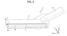
- FIG. 3 is a perspective view of the wire delivery device
- FIG. 4 is a perspective view of the wire delivery device to which the guidewire and catheter are connected.
- the wire feeding device 1 includes a housing 2 , a lever 31 , a connector connecting portion 3 , a guide wire housing portion 4 and a grasping portion 20 .
- the housing 2 has a substantially rectangular parallelepiped shape extending in the axial direction (the X-axis direction in the drawing) when the guide wire GW is attached.
- the housing 2 includes, in addition to the grasping part 20, various components described later for grasping and delivering the guide wire GW.
- the lever 31 is rotatable about a lever rotation shaft 31O, which will be described later, and is a part operated by the operator when feeding the guide wire GW. In this embodiment, the operator can deliver the guide wire GW by gripping and rotating the lever 31 with one hand.
- the connector connection portion 3 is a portion for connecting the attachment portion 60C of the connector 60, and has a pair of connection pieces 3A and 3B extending in the X-axis direction.
- the connection pieces 3A and 3B are made of, for example, an elastic material such as resin, and sandwich the outer peripheral surface of the mounting portion 60C from both sides in the Y-axis direction to connect the connector 60 in a rotatable manner.
- the guide wire housing portion 4 is a portion that houses the guide wire GW to be delivered, extends in the X-axis direction, and is formed in a concave shape that is open in the positive direction of the Z-axis over the entire X-axis direction.
- the grasping portion 20 is a portion capable of grasping the guide wire GW and movable in the X-axis direction. ) is open to the outside.
- the guide wire GW is placed on the surface of the guide wire accommodating portion 4 in the negative direction of the Z axis (here, also referred to as the bottom surface)
- the guide wire GW is placed on the gripping surface portion 21A and the gripping surface portion 22A of the gripping portion 20. is held (arranged) in the gap (arrangement space) between the
- the guide wire GW at the base end side of the connector 60 is placed on the bottom surface of the concave portion of the guide wire housing portion 4. Then, the attachment portion 60C connected to the catheter 51 into which the guide wire GW is inserted is fitted into the connection pieces 3A and 3B to be attached.
- the catheter 51 and the guide wire GW are connected to the wire delivery device 1 in this way, it becomes as shown in FIG.
- the operator can easily adjust the orientation of the catheter 51 by rotating the operation dial 60A.
- a gap is secured between the surface of the rear end portion 60D on the negative direction side of the X axis (the direction opposite to the direction of the arrow of the X axis) and the surface of the housing 2 on the positive direction side of the X axis. Since the catheter 51 is in such a state that the liquid such as blood or medicinal liquid has passed through the catheter 51, it is easy to flow down from the gap, and the structure on the side of the housing 2 can be properly prevented from coming into contact with the liquid. Further, when the lever 31 is in the initial state, the guide wire GW is not gripped as will be described later, so the direction can be adjusted by turning the guide wire GW.
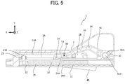
- FIG. 5 is a top cross-sectional view of the wire feeding device in its initial state, and the wire feeding device 1 includes a housing, a grip portion, a compression spring, a slider, a hook, and an ejection switch.
- 6 is a configuration diagram of the grip
- FIG. 7 is an enlarged view of part of the grip
- FIG. 8 is a bottom perspective view of the wire feeding device in its initial state
- FIG. 9 is an injection switch.
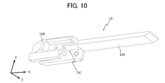
- 10 is a perspective view of a slider
- FIG. 11 is a perspective view of a hook.
- FIG. 7 is an enlarged view of a portion of the grip portion excluding the cylindrical portion.
- FIG. 8 shows a state in which a part of the housing 2 on the negative direction side of the Z-axis is removed from the wire feeding device 1 .
- the bottom perspective views of other drawings in this specification may show the same state.
- the wire feeding device 1 includes a housing 2, a grip portion 20, a compression spring 12, a slider 13, a hook 14, and an ejection switch 45.
- the compression spring 12 is an example of an elastic body.
- the slider 13 and hook 14 are examples of the biasing portion.
- the wire feeding device 1 further includes a lever 31, links 35 and 37, and joints 36 and 38 shown in FIG.
- the lever 31, the links 35, 37, the joints 36, 38, and the slider 13 are examples of the power transmission mechanism
- the slider 13, the hook 14, and the ejection switch 45 are examples of the release portion.
- the housing 2 includes a grip portion accommodating portion 2A that accommodates the grip portion 20 so as to be movable in the X-axis direction, and a slider accommodation portion that accommodates the slider 13 and the hook 14 so as to be movable in the X-axis direction. Part 2B and are formed.
- the housing 2 is formed with a support hole 2C that rotatably supports the cylindrical portion 35A on the one end side of the link 35 .
- the grip portion 20 is movable in the X-axis direction in the grip portion accommodating portion 2A.
- the grasping part 20 can grasp the guide wire GW.
- the gripping portion 20 has a first part 21, a second part 22, a gripping spring 23, and a cylindrical portion 24, as shown in FIG.
- the cylindrical part 24 is a cylindrical part that is connected to the first part 22 in the negative direction of the X axis and extends in the negative direction of the X axis.
- a convex portion 24A is formed on the cylindrical portion 24 on the side of the slider accommodating portion 2B.
- the convex portion 24A can be engaged with the spring hook 14A of the hook 14.
- the cylindrical portion 24 has a stepped portion 24B having a reduced outer diameter in the intermediate portion.
- a compression spring 12 is attached to the stepped portion 24B in the negative direction of the X axis.
- the portion of the compression spring 12 in the positive direction of the X axis contacts the surface of the stepped portion 24B in the negative direction of the X axis, and is located on the outer peripheral side of the portion in the negative direction of the X axis relative to the stepped portion 24B.
- a compression spring 12 is arranged as follows. With such a configuration, when the compression spring 12 is compressed, it is possible to appropriately prevent the compression spring 12 from bending in the X-axis direction and being compressed by the portion of the cylindrical portion 24 on the inner peripheral side.
- the compression spring 12 is, for example, a metal spring, is deformable (compressible) in the X-axis direction, and can apply a biasing force in the positive direction of the X-axis to the grip portion 20 . be.
- the first component 21 has, for example, a grip surface portion 21A formed extending in the X-axis direction and a substantially cylindrical leg portion 21B extending in the Y-axis direction.
- the second part 22 is formed extending in the X-axis direction, and has a gripping surface portion 22A facing the gripping surface portion 21A, concave portions 22B provided in both directions of the Z-axis direction, and through holes into which the leg portions 21B can be inserted. 22C and
- the first component 21 and the second component 22 are combined with the leg portion 21B inserted into the through hole of the through hole portion 22C.
- a gripping spring 23 is attached between the leg portion 21B and the second component 22, and the biasing force of the gripping spring 23 is applied to the surface (gripping surface) of the gripping surface portion 21A on the second component 22 side and the second component 22 side. It acts so that the surface (gripping surface) of the gripping surface portion 22A of 22 on the side of the first component 21 (gripping surface) approaches.
- the gripping surface of the gripping surface portion 21A on the side of the second component 22 and the gripping surface of the gripping surface portion 22A on the side of the first component 21 are separated, and a space (arrangement) is formed between them.
- the guide wire GW can be placed in the space, and then the grasping part 20 can grasp the guide wire GW by the biasing force of the grasping spring 23 .
- This arrangement space can be opened to the outside by an opening extending over the entire movable direction of the grip part 20 .
- the guide wire GW in the concave portion of the guide wire accommodating portion 4, it is guided substantially in the center in the Z-axis direction between the gripping surface of the gripping surface portion 21A and the gripping surface of the gripping surface portion 22A.
- a wire GW can be positioned.
- the leg portion 21B is pushed toward the first component 21 (negative direction of the Y axis) and the gripping spring 23 is compressed, the gripping surface of the gripping surface portion 21A and the gripping surface of the gripping surface portion 22A are brought into contact with each other. Since a space is created by separating them, the guide wire GW is no longer gripped by the gripping part 20 (grip release).
- the concave portion 22B engages with a convex portion (not shown) formed extending in the X-axis direction on both walls in the Z-axis direction of the grip portion accommodating portion 2A, thereby accurately guiding the grip portion 20 in the X-axis direction. act to
- the injection switch 45 has a convex portion 45A, an extension piece 45B, a convex portion 45C, a fixing hole 45D and a spring accommodation portion 45E.
- the convex portion 45A can come into contact with the convex portion 14B (see FIGS. 11 and 13) of the hook 14 and push up the convex portion 14B.
- the extension piece 45B is formed extending in the positive direction of the Y-axis.
- the convex portion 45C is formed at the tip of the extension piece 45B in the positive direction of the Y axis and protrudes in the negative direction of the Z axis.
- the convex portion 45C engages with the convex portion 13B (see FIGS.
- the fixing hole 45D is a hole into which a screw 46 for fixing the ejection switch 45 to the housing 2 so as to be rotatable is inserted.
- the ejection switch 45 is fixed to the housing 2 by screws 46, so that it can rotate around the fixing hole 45D.
- a spring (not shown) that biases the ejection switch 45 in the negative direction of the Y-axis is accommodated in the spring accommodating portion 45E. It should be noted that the injection switch 45 itself may be configured to have elasticity and be biased in the negative direction of the Y-axis without being provided with a spring.
- the slider 13 has an extension 13A extending in the positive direction of the X axis, a projection 13B engageable with the extension piece 45B and the projection 45C of the injection switch 45, and a hook 14. and a mounting portion 13C.
- the extended portion 13A has a plate-like shape with a surface in the negative direction of the Y-axis on the tip end side in the X-axis direction and having a slope such that the thickness becomes thinner toward the tip end side.
- the extension portion 13A is in a state of pushing down the leg portion 21B of the grip portion 20 in the negative direction of the Y-axis.
- the gripping spring 23 is compressed to move the leg portion 21B of the gripping portion 20 in the negative direction of the Y axis.
- the surface of the gripping surface portion 21A on the side of the second component 22 and the surface of the gripping surface portion 22A on the side of the first component 21 are separated, so that the grip of the guide wire GW is released.
- the hook 14 is attached to the attachment portion 13C of the slider.
- the hook 14, as shown in FIG. 11, has a spring hook 14A and a projection 14B.
- the spring hook 14A is engageable with the convex portion 24A of the grip portion 20.
- the convex portion 14B is a portion that contacts the convex portion 45A of the ejection switch 45.
- the hook 14 is elastically deformed, and the spring hook 14A is moved in the same direction.
- the slider 13 and the hook 14 are configured separately, but they may be integrated.
- the lever 31, the links 35, 37, the joints 36, 38, and the slider 13 constitute a power transmission mechanism.
- the lever 31 is a part that is manually rotated by the operator using the wire feeding device 1 .
- the lever 31 is rotatable around a lever rotation shaft 31O.
- the lever 31 and the cylindrical portion 35A of the link 35 are connected via a joint (not shown) so that the turning force can be transmitted from the lever 31 to the link 35.
- the link 35 is configured to rotate together with the rotation of the lever 31 .
- the other end of the link 35 and one end of the link 37 are rotatably connected via a joint 36 .
- the other end of the link 37 and the slider 13 are rotatably connected via a joint 38 .
- the slider 13 is linearly movable in the X-axis direction.
- the power transmission mechanism when the lever 31 is rotated in the R1 direction, the link 35 is rotated in the R2 direction. Move with movement.
- the power transmission mechanism is configured so that the lever 31 can be rotated over the entire range of movement in the X-axis direction, and the links 35 and 37 can be rotated. The length of is adjusted.
- the spring hook 14A engages with the convex portion 24A of the grip portion 20, and when it moves further, the grip portion 20 moves toward the proximal end. side to compress the push spring 12 .
- the projection 45C of the injection switch 45 rides over the projection 13B of the slider 13 in the positive direction of the X axis and engages with each other. As a result, the slider 13 cannot move in the positive direction of the X-axis while the push spring 12 is compressed.
- the convex portion 45A pushes the convex portion 14B in the positive direction of the Y axis, and the portion of the hook 14 on the positive side of the X axis is moved in the positive direction of the Y axis. It is deformed in the positive direction, and the engagement between the spring hook 14A and the convex portion 24A is released. As a result, the deformed state (compressed state) of the compression spring 12 is released at once, and the compression spring 12 pushes the grip portion 20 in the X-axis direction. Since the pressing spring 12 is in contact with the gripping portion 20 , the biasing force of the pressing spring 12 directly acts on the gripping portion 20 .
- FIG. 12 is a top cross-sectional view of the wire feeding device in a ready-to-feed state
- FIG. 13 is a bottom view thereof
- FIG. 14 is a bottom view during feeding
- FIG. 15 is a top cross-sectional view thereof
- FIG. 16 is a top cross-sectional view after delivery.
- the wire feeding device 1 operates in this order to grasp the guide wire GW, move the grasping portion 20 toward the distal end of the guide wire GW, release the grasp of the guide wire GW, and move the grasping portion 20 toward the rear end.
- the grip portion 20, the slider 13, and the hook 14 are configured to be interlocked.
- the guide wire GW is advanced along the blood vessel to the occlusion site.
- the catheter 51 is advanced to the site of obstruction using the guide wire GW as a guide.
- the connector 60 is connected to the catheter hub 52 of the catheter 51 , and the proximal end side of the guide wire GW is inserted into the guide wire accommodating portion 4 of the housing 2 while pushing the connector 60 into the connector connection portion 3 from the positive direction of the Z axis.
- the connector 60 is connected to the wire feeding device 1 by retracting from the positive side of the Z axis.
- the leg portion 21B is pressed in the negative direction of the Y axis by the extension portion 13A, and the gripping spring 23 is compressed. Then, the surface of the gripping surface portion 22A on the side of the first component 21 is separated to form an arrangement space, and the gripping of the guide wire GW by the gripping portion 20 is released. Therefore, as described above, by mounting the catheter 51 into which the guide wire GW has been inserted, the guide wire GW can be easily housed in the installation space. Therefore, the preparation time for delivering the guide wire GW by the wire delivery device 1 can be shortened, and the burden on the patient and operator can be reduced.
- the slider 13 and the hook 14 are slid to the base end side, and as shown in FIG. As the slider 13 moves, the grasping portion 20 moves to the base end side and the compression spring 12 is compressed.
- the slider 13 and the hook 14 slide further to the proximal side, as shown in FIG. , the convex portion 45C of the injection switch 45 climbs over the convex portion 13B of the slider 13 and is positioned in the positive direction of the X axis of the convex portion 13B, and they are engaged with each other.
- the slider 13 cannot move in the positive direction of the X axis, and the compression spring 12 is maintained in a compressed state, so that a state in which delivery is possible (a state in which compression is maintained: a state in which delivery is possible) is achieved.
- the leg portion 21B is pressed in the negative direction of the Y axis by the extension portion 13A, and the gripping spring 23 is compressed. Then, the surface of the gripping surface portion 22A on the side of the first component 21 is separated, and the gripping of the guide wire GW by the gripping portion 20 is released.
- the biasing force of the push spring 12 is applied to move the gripping portion 20 in the distal direction at once, and the gripping portion 20 moves in the distal direction and stops at the distal end position of the gripping portion 20 .
- the extension portion 13A does not come into contact with the leg portion 21B and does not compress the gripping spring 23.
- the guide wire GW is gripped between the surface on the side of the second component 22 and the surface of the grip surface portion 22A on the side of the first component 21 .
- the guide wire GW is maintained in a gripped state from the time it is gripped by the gripping portion 20 until the gripping portion 20 moves to the most distal position.
- the guide wire GW is delivered to the distal end side by a distance D from the position where it is gripped by the gripping part 20 until the gripping part 20 reaches the distal end position. This distance D corresponds to the wire feeding amount by the wire feeding device 1 at one time.
- the lever 31 can be rotated in the same manner as described above and the same operation can be performed.
- the wire feeding device 1 it is possible to apply the urging force accumulated in the compression spring 12 to the guide wire GW to feed out an appropriate amount. Since the biasing force can be applied to the guidewire GW in this manner, the obstruction can be penetrated more effectively by the guidewire GW.
- FIG. 17 is a top view of the wire feeding device in the initial state according to the second embodiment
- FIG. 18 is a top cross-sectional view of the wire feeding device in the initial state
- FIG. 19 is a wire feeding device in the initial state
- Figure 20 is a side view and Figure 20 is a perspective view of the slider of the wire delivery device; Parts similar to those of the wire feeding device 1 according to the first embodiment are denoted by the same reference numerals, and overlapping descriptions are omitted.
- the wire feeding device 201 includes a gripping portion 220 instead of the gripping portion 20, a slider 210 instead of the slider 13, and an adjusting portion 240 in the housing 2. As shown in FIG. 20, the slider 210 does not have the extended portion 13A of the slider 13. As shown in FIG. Parts of the slider 210 that are common to the slider 13 are given the same reference numerals.
- FIG. 21 is an exploded perspective view of a portion of the gripping portion
- FIG. 22 is a perspective view of a portion of the gripping portion in a grip-released state
- FIG. 23 is a side sectional view of the grip-released state
- 24 is a perspective view of the gripped state
- FIG. 25 is a side sectional view of the gripped state.
- the gripping portion 220 has the gripping portion 20 and the cylindrical portion 24 in common, and the other configurations are different. However, in FIGS. 21 to 25, illustration of the cylindrical portion 24 is omitted.
- the gripping portion 220 includes a body portion 221 as an example of a first gripping portion, a facing component 222 as an example of a second gripping portion, a cam portion 223, a grip release spring 224, a support pin 225, and a retaining ring 226. and have
- the body portion 221 has a gripping surface 221A and a wall portion 221B.
- the grip surface 221A is a surface in the negative direction of the Y axis that grips the guide wire GW, and for example, a rubber member may be attached to this surface.
- the gripping surface 221A has a surface that intersects the movable direction (X-axis direction) of the gripping portion 220 .
- the wall portion 221B has a hole 221C into which a support pin 225 that rotatably supports the cam portion 223 is inserted, and a hole 221D into which a support pin 225 that rotatably supports the opposing component 222 is inserted.
- the cam portion 223 has an operation convex portion 223A, a through hole 223B, and a contact surface 223C.
- the operation convex portion 223A is provided on the side surface of the cam portion 223 and is a portion for operating the state of the cam portion 223 .
- the through hole 223B is a hole into which a pin 225 for rotationally supporting the cam portion 223 is inserted.
- 223 C of contact surfaces are surfaces which contact the surface of the positive direction of the Y-axis of the opposing component 222. As shown in FIG.
- a cross-sectional shape (the same shape as the side surface) of the contact surface 223C on a plane perpendicular to the X axis has a linear portion 223D and a curved portion 223E.
- the cam portion 223 can be maintained in a state in which the grip portion 220 grips the guide wire GW.
- the facing component 222 has a gripping surface 222A and a through hole 222B.
- the gripping surface 222A is a surface in the positive direction of the Y-axis that grips the guide wire GW, and has a surface shape corresponding to the gripping surface 221A of the main body 221 .
- a rubber member may be attached to the grip surface 222A.
- the through-hole 222B is a hole into which a pin 225 is inserted to support rotation of the opposing component 222. As shown in FIG.
- the grip releasing spring 224 is biased and arranged so that the distance between the facing surfaces of the main body portion 221 and the facing component 222 widens.
- the grip release spring 224 is set so that the cam portion 223 and the opposing component 222 are positioned in the positive direction of the Z axis relative to the maximum outer shape portion 223F. , or the linear portion 223D, the gap between the opposing surfaces of the main body portion 221 and the opposing component 222 is widened.
- the support pin 225 is a columnar member having a head portion 225A at a first end and a groove portion 225B into which a snap ring 226 is fitted at a second end opposite to the first end. .
- the snap ring 226 prevents the support pin 225 from falling out of the holes 221C and 221D by being attached to the groove 225B of the support pin 225.
- the support pin 225 is inserted into the hole 221D in the negative direction of the X axis, the through hole 222B of the opposing part 222, and the positive direction of the X axis of the body portion 221.
- the retaining ring 226 is attached to the groove 225B of the support pin 225 .
- the support pin 225 is inserted into the hole 221C of the body portion 221 in the negative direction of the X axis, the through hole 223B of the cam portion 223, and the hole 221C of the body portion 221 in the positive direction of the X axis.
- a retaining ring 226 is attached to the .
- the grip portion 220 shown in FIG. 22 is completed.
- the grasping part 220 is in a state in which the grip of the guide wire GW is released (grip release state).
- the gripping portion 220 is such that the linear portion 223D of the contact surface 223C of the cam portion 223 is in contact with the surface of the corresponding component 222 in the positive direction of the Y axis, and the gripping surface 222A is in contact. and the grip surface 221A are separated from each other.
- the gripping portion 220 is in contact with the surface of the corresponding component 222 in the positive Y-axis direction at a position in the negative direction of the Z-axis rather than the maximum outer shape portion 223F, and the gripping surface 222A is in contact with the gripping surface 222A. and the grip surface 221A are in contact with each other. Since the distance from the rotation axis of the cam portion 223 is longer than the contact position, the maximum outer shape portion 223F suppresses the movement of the cam portion 223 in the direction opposite to the R3 direction. 222A and the gripping surface 221A are kept in contact with each other.
- the adjustment portion 240 is a substantially plate-shaped member, and as shown in FIG. 19, is arranged in a range that includes the moving range in the X-axis direction of the operation convex portion 223A on the positive direction side of the Y-axis of the grip portion 220. .
- the adjustment portion 240 has an adjustment frame 240A that can adjust the position of the operation convex portion 223A.
- the adjustment frame 240A guides the operation convex portion 223A as indicated by the arrow D1, and the grip portion 20 is moved to the position in the most negative direction of the X axis.
- the operation convex portion 223A is guided to a position in the negative direction of the Z axis, that is, a position where the grip portion 20 grips the guide wire GW.
- the adjusting frame 240A guides the guide convex portion 223A as indicated by the arrow D2, and the gripping portion 20 moves to the position in the most positive direction of the X axis.
- the operation convex portion 223A guides to the position in the positive direction of the Z axis, that is, the position where the grasping portion 20 releases the grip of the guide wire GW.
- the adjustment frame 240A has a rhombic shape whose apex is the position where the grip portion 20 grips or releases the guide wire GW, that is, the position where the operation convex portion 223A stops. It's becoming
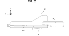
- FIG. 26 is a top view of the wire feeding device in a ready-to-deliver state
- FIG. 27 is a cross-sectional top view in the ready-to-delivery state
- FIG. 28 is a side view thereof. 26 to 28, the guide wire GW, catheter 51, connector 60, etc. are not shown, but the catheter 51 and connector 60 are connected to the wire delivery device 201. Subsequent processing will be described.
- the wire delivery device 201 operates in this order to grasp the guide wire GW, move the grasping portion 220 toward the distal end of the guide wire GW, release the grasp of the guide wire GW, and move the grasping portion 220 toward the rear end.
- the grip portion 220 and the slider 210 are configured to be interlocked.
- the operation convex portion 223A of the grip portion 220 is guided by the adjustment frame 240A of the adjustment portion 240 to the position where the grip of the grip portion 220 is released. , the grip surface 222A and the grip surface 221A are separated from each other, and the grip of the guide wire GW by the grip portion 220 is released.
- the slider 13 and the hook 14 are moved to the proximal side. 27 and 28, the projecting portion 45C of the extension piece 45B of the injection switch 45 overcomes the projecting portion 13B of the slider 210 and is positioned in the positive direction of the X axis of the projecting portion 13B. and engage each other. As a result, the slider 13 cannot move in the positive direction of the X axis, and the compression spring 12 is maintained in a compressed state, so that a state in which delivery is possible (a state in which compression is maintained: a state in which delivery is possible) is achieved.
- the adjustment frame 240A of the adjustment portion 240 guides the operation convex portion 223A to a position where the grip portion 220 is gripped, so that the guide wire GW is gripped between the grip surface 222A and the grip surface 221A. It will happen.
- the convex portion 45A pushes the convex portion 14B of the hook 14 in the positive direction of the Y axis, as in the case shown in FIG.
- the spring hook 14A moves in the positive direction of the Y-axis as in the case shown in FIG.
- the convex portion 45C of the ejection switch 45 moves in the positive direction from the surface of the slider 210 in the positive direction of the Y axis and is no longer engaged with the convex portion 13B of the slider 210, and the slider 210 moves in the positive direction of the X axis. becomes movable.
- the biasing force of the push spring 12 is applied to the movement of the grasping portion 220 in the distal direction at once, and the grasping portion 220 that grasps the guide wire GW moves in the distal direction and stops at the distal end position.
- the operation convex portion 223A is guided by the adjustment frame 240A to the position where the gripping of the gripping portion 220 is released, so that the gripping portion 220 is able to grip the guide wire GW. release.
- the grasping part 220 moves while maintaining the state of grasping the guide wire GW from the rearmost position to before reaching the most distal position.
- the guide wire GW is delivered to the distal side by the distance from the rear end position of the gripping portion 220 to the position where the gripping of the gripping portion 220 is released.
- the slider 210 moves in the positive direction of the X axis, and the wire feeding device 201 can be returned to the initial state shown in FIG. If the guide wire GW needs to be delivered continuously, the lever 31 can be rotated in the same manner as described above and the same operation can be performed.
- the wire feeding device 201 it is possible to apply the urging force accumulated in the compression spring 12 to the guide wire GW and feed the guide wire GW in an appropriate amount. Since the biasing force of the compression spring 12 can be applied to the guide wire GW in this manner, the obstruction can be effectively penetrated by the guide wire GW.
- a metal spring is used as the compression spring 12, but other types of elastic bodies such as rubber cords and leaf springs may be used. It can be material.
- An elastic body may be provided so as to extend against the movement of the body, and the extension of the elastic body may increase the biasing force.
- a mechanism for adjusting the movable range of the gripping parts 20 and 220 in the X-axis direction for example, a mechanism for moving the position of the wall in the X-axis direction that determines the movable range may be provided. With this configuration, the amount of wire fed by the wire feeding device can be adjusted easily and appropriately.
- a mechanism for adjusting the amount of compression of the compression spring 12 in the initial state for example, a mechanism for moving the position of the wall on the proximal end side of the compression spring 12 may be provided. By doing so, it is possible to easily and appropriately adjust the urging force applied to the gripping portions 20 and 220 in the wire feeding device.
- the guide wire GW is delivered by the operator manually turning the lever 31, it may be delivered by a motor operated by electric power.
- the link 35 may be rotated by power of a motor.
- the motor may be stopped when the link 35 is rotated by a predetermined angle.
- a switch for driving the motor may be provided, and when the switch is pressed once, the motor may be driven to rotate the link 35 by a predetermined angle.
- Wire feeding device (first embodiment) 2 Housing 2A Grasping Part Accommodating Part 2B Slider Accommodating Part 2C Support Hole 3 Connector Connecting Part 3A, 3B Connecting Piece 4 Guide Wire Accommodating Part 12 Pushing Spring 13 Slider 13A Extension 13B Projection 13C Mounting Part 14 Hook 14A Spring Hook 14B Convex portion 20 Grip portion 21 First component 21A Grip surface portion 21B Leg portion 22 Second component 22A Grip surface portion 22B Concave portion 22C Through hole 23 Grip spring 24 Cylindrical portion 24A Convex portion 24B Stepped portion 31 Lever 31O Lever rotating shaft 35,37 Link 35A Cylindrical portion 36, 38 Joint 45 Injection switch 45A Convex portion 45B Extension piece 45C Convex portion 45D Fixing hole 45E Spring housing portion 46 Screw 51 Catheter 52 Catheter hub 52A Rear end portion 60 Connector 60A Dial portion 60B Through hole 60C Mounting portion 60D Rear end part 201 wire feeding device (second embodiment) 210 slider 2
Abstract
The present invention is configured to enable the movement amount of a wire to be set to an appropriate amount, and to enable the wire to be fed using an appropriate force. A wire feed device that feeds a guide wire in a distal end direction, wherein: the device comprises a gripping portion 20 capable of gripping and releasing the guide wire and capable of moving the guide wire in the distal-end direction and in a rear-end direction, an elastic body 12 capable of biasing the gripping portion 20 in the distal-end direction, a slider 13 and a hook 14 that deform the elastic body 12 to increase the biasing force on the gripping portion 20 in the distal-end direction, and a projection portion of an ejection switch 45 that releases the deformed state of the elastic body 12 subjected to the increased biasing force; by moving the gripping portion 20 in the distal-end direction with the biasing force exerted by the elastic body 12, the deformed state of which is released by the projection portion of the ejection switch 45, the guide wire gripped by the gripping portion 20 is fed in the distal-end direction.
Description
本発明は、ワイヤを送出するワイヤ送出装置に関する。
The present invention relates to a wire feeding device for feeding a wire.
慢性完全閉塞(CTO:Chronic total occlusion)のような血管を閉塞する閉塞物を除去して血流を改善する際には、例えば、柔らかいガイドワイヤにより閉塞物を穿通できるかを試し、閉塞物を穿通できない場合に、徐々に固い順行性ガイドワイヤに交換することが行われる。
When removing an obstruction that obstructs a blood vessel such as chronic total occlusion (CTO) to improve blood flow, for example, try to penetrate the obstruction with a soft guide wire, and remove the obstruction. Gradually changing to a stiffer anterograde guidewire is performed if penetration is not possible.
この方法においては、ガイドワイヤを交換する手間がかかるとともに、ガイドワイヤを複数本使用するためにコストがかかる。
In this method, it takes time and effort to replace the guidewire, and the use of multiple guidewires is costly.
また、ガイドワイヤにより閉塞物を穿通させる際には、手技者が手でガイドワイヤを摘まんで操作するために、ガイドワイヤを送出する距離は、手技者の感覚によるものとなっていた。
In addition, when penetrating an obstruction with a guide wire, the operator manually grips and manipulates the guide wire, so the distance to which the guide wire is delivered depends on the operator's sense.
これに対して、医療用ワイヤを所定の移動量で送り出すことができ、医療用ワイヤの押し付け力を良好に伝達することができる技術として、例えば、特許文献1に記載の技術が知られている。
On the other hand, for example, the technique described in Patent Literature 1 is known as a technique capable of sending out a medical wire by a predetermined amount of movement and capable of satisfactorily transmitting the pressing force of the medical wire. .
特許文献1に記載の技術では、手技者はスプリングを押圧することにより医療用ワイヤを送出する。このため、医療用ワイヤに対する押し付け力は、比較的限られてしまい、医療用ワイヤにより閉塞物を穿通させるために十分でない場合があり、閉塞物を穿通させるために、医療用ワイヤを交換する必要がでてくる。このため、医療用ワイヤを交換する手間がかかるとともに、医療用ワイヤを複数本使用するためにコストがかかるという問題が解決できない。
With the technology described in Patent Document 1, the operator pushes out the medical wire by pressing the spring. As such, the compressive force against the medical wire is relatively limited and may not be sufficient to cause the medical wire to penetrate the obstruction, requiring replacement of the medical wire to penetrate the obstruction. comes out. For this reason, it takes time and effort to replace the medical wire, and the problem of high costs due to the use of a plurality of medical wires cannot be solved.
また、特許文献1の技術においては、医療用ワイヤを保持する把持部材が所定の移動量を超えて先端側に移動したときに、医療用ワイヤの把持した状態を維持する係合部材と把持部材との係合を解除することにより、医療用ワイヤの移動量が所定の移動量を超えないようにしているが、係合部材と把持部材との係合が解除されるタイミングによって、医療用ワイヤの移動量が変動する虞がある。
In addition, in the technique of Patent Document 1, when the grasping member holding the medical wire moves to the distal end side by exceeding a predetermined amount of movement, the engaging member and the grasping member maintain the grasping state of the medical wire. By releasing the engagement with the medical wire, the amount of movement of the medical wire is prevented from exceeding a predetermined amount of movement. may fluctuate.
本発明は、以上のような事情に基づいてなされたものであり、その目的は、ワイヤの移動量を適切な量にすることができるとともに、ワイヤを適切な力で送出することができるようにすることにある。
SUMMARY OF THE INVENTION The present invention has been made based on the above circumstances, and an object of the present invention is to make it possible to adjust the amount of movement of the wire to an appropriate amount and to feed the wire with an appropriate force. to do.
かかる目的を達成するために、第1の観点に係るワイヤ送出装置は、ワイヤを先端方向に送出するワイヤ送出装置であって、前記ワイヤを把持可能及び把持解除可能且つ前記先端方向及び後端方向に移動可能な把持部と、前記把持部を前記先端方向へ付勢可能な弾性体と、前記弾性体を変形させて前記把持部に対する前記先端方向への付勢力を増加させる付勢部と、前記付勢部により付勢力が増加された前記弾性体の変形状態を解放する解放部と、を備え、前記解放部により変形状態が解放された前記弾性体による付勢力によって前記把持部を前記先端方向に移動させることにより、前記把持部に把持された前記ワイヤを前記先端方向に送出する。
In order to achieve such an object, a wire feeding device according to a first aspect is a wire feeding device for feeding a wire in a distal direction, which is capable of gripping and releasing the wire and an elastic body capable of urging the gripping part in the distal direction; an urging part that deforms the elastic body to increase the urging force on the gripping part in the distal direction; a releasing portion for releasing the deformed state of the elastic body whose urging force is increased by the urging portion, wherein the urging force of the elastic body whose deformed state is released by the releasing portion pushes the gripping portion to the distal end; By moving in the direction, the wire gripped by the gripping portion is delivered in the distal direction.
上記ワイヤ送出装置において、前記把持部は、前記ワイヤを挟持する第1挟持部及び第2挟持部と、前記第1挟持部と前記第2挟持部との間隔を調整可能なカムとを有するようにしてもよい。
In the above wire feeding device, the gripping section has a first clamping section and a second clamping section for clamping the wire, and a cam capable of adjusting the distance between the first clamping section and the second clamping section. can be
上記ワイヤ送出装置において、前記把持部の移動に伴って、前記カムによる前記第1挟持部と前記第2挟持部との間隔を調整する調整部をさらに有するようにしてもよい。
The wire feeding device may further include an adjustment section that adjusts the distance between the first holding section and the second holding section by the cam as the holding section moves.
上記ワイヤ送出装置において、前記把持部を前記後端方向に移動させて前記弾性体を圧縮させるように構成されていてもよい。
The wire feeding device may be configured so that the gripping portion is moved in the rear end direction to compress the elastic body.
本発明によると、ワイヤの移動量を適切な量にすることができるとともに、ワイヤを適切な力で送出することができる。
According to the present invention, the amount of movement of the wire can be set to an appropriate amount, and the wire can be delivered with an appropriate force.
実施形態に係るワイヤ送出装置について図面を参照して説明するが、本発明は、当該図面に記載の実施形態のみに限定されるものではない。
Although the wire feeding device according to the embodiment will be described with reference to the drawings, the present invention is not limited only to the embodiments described in the drawings.
本明細書において、「ガイドワイヤ」とは、血管などの体腔内の術部に押し進められ、その術部にカテーテルを導くために用いられる医療用のガイドワイヤを意味する。
As used herein, the term "guidewire" means a medical guidewire that is pushed into a surgical site within a body cavity such as a blood vessel and used to guide a catheter to the surgical site.
本明細書において、「先端側」及び「先端方向」とは、ガイドワイヤの長手方向に沿った方向(ガイドワイヤの軸方向に沿う方向)で、ガイドワイヤにより穿通させる閉塞物が位置する側及び方向を意味する。「後端側」及び「後端方向」とは、先端側及び方向の逆である。また、「基端側」とは、ガイドワイヤの長手方向に沿った方向に沿う方向であって、先端側と反対側の方向を意味する。また、「先端」とは、任意の部材または部位における先端側の端部、「基端」とは、任意の部材または部位における基端側の端部をそれぞれ示す。
As used herein, the terms "distal side" and "distal direction" refer to the direction along the longitudinal direction of the guidewire (the direction along the axial direction of the guidewire), and means direction. The terms "rearward" and "rearward" are opposite to the distal side and direction. Also, the term "proximal side" means a direction along the longitudinal direction of the guidewire, which is opposite to the distal side. In addition, the term “distal end” refers to the distal end of any member or site, and the term “basal end” refers to the proximal end of any member or site.
[第1実施形態]
第1実施形態に係るワイヤ送出装置1(図3参照)は、ワイヤの一例としてのガイドワイヤを送出する装置である。ガイドワイヤは、例えば、血管などの体腔内の術部に押し進められ、その術部の閉塞物を穿通させるために使用される。ワイヤ送出装置1は、ガイドワイヤが挿入されたカテーテルを装置に接続させて使用される。 [First embodiment]
A wire delivery device 1 (see FIG. 3) according to the first embodiment is a device for delivering a guide wire as an example of a wire. A guide wire is used, for example, to be advanced to a surgical site in a body cavity such as a blood vessel, and to penetrate an obstruction in the surgical site. Thewire delivery device 1 is used by connecting a catheter into which a guide wire is inserted.
第1実施形態に係るワイヤ送出装置1(図3参照)は、ワイヤの一例としてのガイドワイヤを送出する装置である。ガイドワイヤは、例えば、血管などの体腔内の術部に押し進められ、その術部の閉塞物を穿通させるために使用される。ワイヤ送出装置1は、ガイドワイヤが挿入されたカテーテルを装置に接続させて使用される。 [First embodiment]
A wire delivery device 1 (see FIG. 3) according to the first embodiment is a device for delivering a guide wire as an example of a wire. A guide wire is used, for example, to be advanced to a surgical site in a body cavity such as a blood vessel, and to penetrate an obstruction in the surgical site. The
ワイヤ送出装置1の詳細を説明する前に、それに接続されるガイドワイヤ及びカテーテルを各図を参照して説明する。図1は、第1実施形態に係るワイヤ送出装置に接続されるガイドワイヤ及びカテーテルと、ワイヤ送出装置に接続するためのコネクタと、を説明する図であり、図2は、それらの接続状態を示す図である。
Before explaining the details of the wire delivery device 1, the guide wire and catheter connected thereto will be explained with reference to each figure. FIG. 1 is a diagram illustrating a guide wire and a catheter connected to a wire delivery device according to the first embodiment, and a connector for connecting to the wire delivery device, and FIG. 2 shows their connection state. FIG. 4 is a diagram showing;
ガイドワイヤGWは中空状のカテーテル51に挿入される。カテーテル51の基端側には、その向きを調整するためのカテーテルハブ52が回転不能に装着されている。図1(A)の例では、図面左側が患者の体内側(先端側)となり、図面右側が患者の体外側(基端側)となる。
A guide wire GW is inserted into a hollow catheter 51 . A catheter hub 52 for adjusting its orientation is non-rotatably mounted on the proximal end side of the catheter 51 . In the example of FIG. 1A, the left side of the drawing is the inside of the patient's body (distal side), and the right side of the drawing is the outside of the patient's body (base end).
カテーテル51は、図2に示すようにコネクタ60に接続され、コネクタ60を介してワイヤ送出装置1に接続される。コネクタ60は、図1(B)に示すように、ダイヤル部60Aと取付部60Cと後端部60Dとを有する。ダイヤル部60Aは、手技者が、コネクタ60と接続されたカテーテル51の方向を操作するための部位である。取付部60Cは、円筒状に形成され、ワイヤ送出装置1の後述するコネクタ接続部3(図3参照)に取り付けるための部位である。取付部60Cの軸方向の長さは、コネクタ接続部3の後述する接続片3A,3BのX軸方向の幅とほぼ同じとなっている。後端部60Dは、取付部60Cの円筒よりも大きい径の円盤状に形成されている。後端部60Dは、コネクタ接続部3に対してコネクタ60のX軸方向の位置決めをするために作用する。
The catheter 51 is connected to a connector 60 as shown in FIG. 2 and connected to the wire delivery device 1 via the connector 60 . The connector 60, as shown in FIG. 1B, has a dial portion 60A, a mounting portion 60C, and a rear end portion 60D. The dial part 60A is a part for operating the direction of the catheter 51 connected to the connector 60 by the operator. The attachment portion 60C is formed in a cylindrical shape and is a portion for attachment to a connector connection portion 3 (see FIG. 3) of the wire feeding device 1, which will be described later. The length of the mounting portion 60C in the axial direction is substantially the same as the width in the X-axis direction of connecting pieces 3A and 3B of the connector connecting portion 3, which will be described later. The rear end portion 60D is formed in a disc shape with a diameter larger than the cylinder of the mounting portion 60C. The rear end portion 60</b>D acts to position the connector 60 in the X-axis direction with respect to the connector connection portion 3 .
コネクタ60には、長手方向に延びる貫通孔60Bが形成されている。貫通孔60Bは、カテーテルハブ52の後端部52Aと係合するように構成されている。カテーテルハブ52の後端部52Aを貫通孔60Bに係合させると、カテーテルハブ52とコネクタ60とは結合され、一体回転可能となる。
A through hole 60B extending in the longitudinal direction is formed in the connector 60 . Throughbore 60B is configured to engage rear end 52A of catheter hub 52 . When the rear end portion 52A of the catheter hub 52 is engaged with the through-hole 60B, the catheter hub 52 and the connector 60 are coupled and rotatable together.
図3は、ワイヤ送出装置の斜視図であり、図4は、ガイドワイヤ及びカテーテルを接続したワイヤ送出装置の斜視図である。ワイヤ送出装置1は、筐体2と、レバー31と、コネクタ接続部3と、ガイドワイヤ収容部4と、把持部20と、を備える。
FIG. 3 is a perspective view of the wire delivery device, and FIG. 4 is a perspective view of the wire delivery device to which the guidewire and catheter are connected. The wire feeding device 1 includes a housing 2 , a lever 31 , a connector connecting portion 3 , a guide wire housing portion 4 and a grasping portion 20 .
筐体2は、ガイドワイヤGWを装着した場合におけるその軸方向(図面X軸方向)に延びた略直方体形状である。筐体2は、内部に、把持部20の他、ガイドワイヤGWを把持して送出するための後述する各種構成を含む。レバー31は、後述するレバー回転軸31Oを中心として回動可能となっており、ガイドワイヤGWを送出する際に手技者が操作する部位である。本実施形態では、手技者は、片手でレバー31を握って回動させることにより、ガイドワイヤGWを送出することができる。
The housing 2 has a substantially rectangular parallelepiped shape extending in the axial direction (the X-axis direction in the drawing) when the guide wire GW is attached. The housing 2 includes, in addition to the grasping part 20, various components described later for grasping and delivering the guide wire GW. The lever 31 is rotatable about a lever rotation shaft 31O, which will be described later, and is a part operated by the operator when feeding the guide wire GW. In this embodiment, the operator can deliver the guide wire GW by gripping and rotating the lever 31 with one hand.
コネクタ接続部3は、コネクタ60の取付部60Cを接続するための部位であり、X軸方向に延びる1対の接続片3A,3Bを有する。接続片3A,3Bは、例えば、樹脂等の弾性体で構成され、取付部60Cの外周面をY軸方向の両側から挟み込んで、コネクタ60を回転可能に接続する。ガイドワイヤ収容部4は、送出対象のガイドワイヤGWを収容する部位であり、X軸方向に延び、X軸方向の全体に亘ってZ軸の正方向が開放された凹状に形成されている。把持部20は、ガイドワイヤGWを把持可能且つX軸方向に移動可能な部位であり、ガイドワイヤ収容部4のX軸方向の中間部に配置され、後述する把持面部21A及び22A(図6参照)を外部に開放させた状態となっている。ガイドワイヤGWをガイドワイヤ収容部4のZ軸の負方向の面(ここでは、底面ともいう)に載置した場合には、ガイドワイヤGWは、把持部20の把持面部21Aと把持面部22Aとの隙間(配置空間)に保持(配置)されるようになっている。
The connector connection portion 3 is a portion for connecting the attachment portion 60C of the connector 60, and has a pair of connection pieces 3A and 3B extending in the X-axis direction. The connection pieces 3A and 3B are made of, for example, an elastic material such as resin, and sandwich the outer peripheral surface of the mounting portion 60C from both sides in the Y-axis direction to connect the connector 60 in a rotatable manner. The guide wire housing portion 4 is a portion that houses the guide wire GW to be delivered, extends in the X-axis direction, and is formed in a concave shape that is open in the positive direction of the Z-axis over the entire X-axis direction. The grasping portion 20 is a portion capable of grasping the guide wire GW and movable in the X-axis direction. ) is open to the outside. When the guide wire GW is placed on the surface of the guide wire accommodating portion 4 in the negative direction of the Z axis (here, also referred to as the bottom surface), the guide wire GW is placed on the gripping surface portion 21A and the gripping surface portion 22A of the gripping portion 20. is held (arranged) in the gap (arrangement space) between the
ワイヤ送出装置1に対して、カテーテル51及びガイドワイヤGWを接続する場合には、コネクタ60よりも基端側となる部分のガイドワイヤGWを、ガイドワイヤ収容部4の凹状部の底面に載置し、ガイドワイヤGWが挿入されたカテーテル51に接続された取付部60Cを接続片3A,3Bにはめ込んで装着させることとなる。このように、ワイヤ送出装置1にカテーテル51及びガイドワイヤGWを接続すると、図4に示すようになる。このように、カテーテル51及びガイドワイヤGWをワイヤ送出装置1に接続した状態においては、操作ダイヤル60Aを手技者が回転させることにより、カテーテル51の向きを容易に調整することができる。この状態では、後端部60DのX軸の負方向側(X軸の矢印の方向と逆の方向)の面と筐体2のX軸の正方向側の面との間に隙間が確保されている状態となっているので、カテーテル51を通過した血液や薬液等の液体は、その隙間から流れ落ちやすくなり、筐体2側の構成が液体と接触することを適切に防止することができる。また、レバー31を初期状態としている場合には、後述するようにガイドワイヤGWが把持されていないので、ガイドワイヤGWを回すことでその向きを調整することができる。
When connecting the catheter 51 and the guide wire GW to the wire delivery device 1, the guide wire GW at the base end side of the connector 60 is placed on the bottom surface of the concave portion of the guide wire housing portion 4. Then, the attachment portion 60C connected to the catheter 51 into which the guide wire GW is inserted is fitted into the connection pieces 3A and 3B to be attached. When the catheter 51 and the guide wire GW are connected to the wire delivery device 1 in this way, it becomes as shown in FIG. Thus, in a state where the catheter 51 and the guide wire GW are connected to the wire delivery device 1, the operator can easily adjust the orientation of the catheter 51 by rotating the operation dial 60A. In this state, a gap is secured between the surface of the rear end portion 60D on the negative direction side of the X axis (the direction opposite to the direction of the arrow of the X axis) and the surface of the housing 2 on the positive direction side of the X axis. Since the catheter 51 is in such a state that the liquid such as blood or medicinal liquid has passed through the catheter 51, it is easy to flow down from the gap, and the structure on the side of the housing 2 can be properly prevented from coming into contact with the liquid. Further, when the lever 31 is in the initial state, the guide wire GW is not gripped as will be described later, so the direction can be adjusted by turning the guide wire GW.
次に、ワイヤ送出装置1について詳細に説明する。図5は、ワイヤ送出装置の初期状態における上面断面図であり、ワイヤ送出装置1は、筐体と把持部と押しばねとスライダとフックと射出スイッチとを備える。図6は、把持部の構成図であり、図7は、把持部の一部の拡大図であり、図8は、ワイヤ送出装置の初期状態における底面斜視図であり、図9は、射出スイッチの斜視図であり、図10は、スライダの斜視図であり、図11は、フックの斜視図である。図7は、把持部の円柱部を除いた部分の拡大図である。図8は、ワイヤ送出装置1からZ軸の負方向側の筐体2の一部を取り外した状態を示してある。また、本明細書における他の図の底面斜視図においても同様の状態を示す場合がある。
Next, the wire feeding device 1 will be described in detail. FIG. 5 is a top cross-sectional view of the wire feeding device in its initial state, and the wire feeding device 1 includes a housing, a grip portion, a compression spring, a slider, a hook, and an ejection switch. 6 is a configuration diagram of the grip, FIG. 7 is an enlarged view of part of the grip, FIG. 8 is a bottom perspective view of the wire feeding device in its initial state, and FIG. 9 is an injection switch. 10 is a perspective view of a slider, and FIG. 11 is a perspective view of a hook. FIG. 7 is an enlarged view of a portion of the grip portion excluding the cylindrical portion. FIG. 8 shows a state in which a part of the housing 2 on the negative direction side of the Z-axis is removed from the wire feeding device 1 . Also, the bottom perspective views of other drawings in this specification may show the same state.
ワイヤ送出装置1は、筐体2と把持部20と押しばね12とスライダ13とフック14と射出スイッチ45とを備える。押しばね12は、弾性体の一例である。スライダ13及びフック14は、付勢部の一例である。ワイヤ送出装置1は、更に、図8に示すレバー31と、リンク35,37と、ジョイント36,38と、を備える。ここで、レバー31、リンク35,37、ジョイント36,38及びスライダ13は、動力伝達機構の一例であり、スライダ13、フック14及び射出スイッチ45は、解放部の一例である。
The wire feeding device 1 includes a housing 2, a grip portion 20, a compression spring 12, a slider 13, a hook 14, and an ejection switch 45. The compression spring 12 is an example of an elastic body. The slider 13 and hook 14 are examples of the biasing portion. The wire feeding device 1 further includes a lever 31, links 35 and 37, and joints 36 and 38 shown in FIG. Here, the lever 31, the links 35, 37, the joints 36, 38, and the slider 13 are examples of the power transmission mechanism, and the slider 13, the hook 14, and the ejection switch 45 are examples of the release portion.
筐体2には、図5に示すように、把持部20をX軸方向に移動可能に収容する把持部収容部2Aと、スライダ13及びフック14をX軸方向に移動可能に収容するスライダ収容部2Bと、が形成されている。筐体2には、リンク35の一端側の円筒部35Aを回動可能に支持する支持孔2Cが形成されている。
As shown in FIG. 5, the housing 2 includes a grip portion accommodating portion 2A that accommodates the grip portion 20 so as to be movable in the X-axis direction, and a slider accommodation portion that accommodates the slider 13 and the hook 14 so as to be movable in the X-axis direction. Part 2B and are formed. The housing 2 is formed with a support hole 2C that rotatably supports the cylindrical portion 35A on the one end side of the link 35 .
把持部20は、把持部収容部2AにおいてX軸方向に移動可能である。把持部20は、ガイドワイヤGWを把持可能である。把持部20は、図6に示すように、第1部品21と第2部品22と把持ばね23と円柱部24とを有する。
The grip portion 20 is movable in the X-axis direction in the grip portion accommodating portion 2A. The grasping part 20 can grasp the guide wire GW. The gripping portion 20 has a first part 21, a second part 22, a gripping spring 23, and a cylindrical portion 24, as shown in FIG.
円柱部24は、第1部品22のX軸の負方向に接続され、X軸の負方向に延びる円筒状の部品である。円柱部24には、スライダ収容部2B側に凸部24Aが形成されている。凸部24Aは、フック14のばね用フック14Aに係合可能となっている。また、円柱部24は、中間部分に外径が縮小する段差部24Bを有している。段差部24BのX軸の負方向に押しばね12が装着される。具体的には、段差部24BのX軸の負方向の面に押しばね12のX軸の正方向の部分が接触し、段差部24BよりもX軸の負方向の部位の外周側に位置するように押しばね12が配置されている。このような構成により、押しばね12が圧縮された場合に、その内周側の円柱部24の部分により押しばね12がX軸方向から曲がって圧縮されてしまうことを適切に防止できる。押しばね12は、例えば、金属製のばねであり、X軸方向に対して変形可能(圧縮可能)となっており、把持部20に対してX軸の正方向への付勢力を印加可能である。
The cylindrical part 24 is a cylindrical part that is connected to the first part 22 in the negative direction of the X axis and extends in the negative direction of the X axis. A convex portion 24A is formed on the cylindrical portion 24 on the side of the slider accommodating portion 2B. The convex portion 24A can be engaged with the spring hook 14A of the hook 14. As shown in FIG. In addition, the cylindrical portion 24 has a stepped portion 24B having a reduced outer diameter in the intermediate portion. A compression spring 12 is attached to the stepped portion 24B in the negative direction of the X axis. Specifically, the portion of the compression spring 12 in the positive direction of the X axis contacts the surface of the stepped portion 24B in the negative direction of the X axis, and is located on the outer peripheral side of the portion in the negative direction of the X axis relative to the stepped portion 24B. A compression spring 12 is arranged as follows. With such a configuration, when the compression spring 12 is compressed, it is possible to appropriately prevent the compression spring 12 from bending in the X-axis direction and being compressed by the portion of the cylindrical portion 24 on the inner peripheral side. The compression spring 12 is, for example, a metal spring, is deformable (compressible) in the X-axis direction, and can apply a biasing force in the positive direction of the X-axis to the grip portion 20 . be.
第1部品21は、図7に示すように、例えば、X軸方向に延びて形成されている把持面部21Aと、Y軸方向に延びる略円柱状の脚部21Bと、を有する。第2部品22は、X軸方向に延びて形成され、把持面部21Aと対向する把持面部22Aと、Z軸方向の両方向に備えられた凹状部22Bと、脚部21Bが挿入可能な貫通孔部22Cと、を有する。
As shown in FIG. 7, the first component 21 has, for example, a grip surface portion 21A formed extending in the X-axis direction and a substantially cylindrical leg portion 21B extending in the Y-axis direction. The second part 22 is formed extending in the X-axis direction, and has a gripping surface portion 22A facing the gripping surface portion 21A, concave portions 22B provided in both directions of the Z-axis direction, and through holes into which the leg portions 21B can be inserted. 22C and
第1部品21と第2部品22とは、脚部21Bが、貫通孔部22Cの貫通孔に挿入された状態で組み合わされている。脚部21Bと第2部品22との間には把持ばね23が取り付けられており、把持ばね23の付勢力が、把持面部21Aの第2部品22側の面(把持面)と、第2部品22の把持面部22Aの第1部品21側の面(把持面)とが近づくように作用する。
The first component 21 and the second component 22 are combined with the leg portion 21B inserted into the through hole of the through hole portion 22C. A gripping spring 23 is attached between the leg portion 21B and the second component 22, and the biasing force of the gripping spring 23 is applied to the surface (gripping surface) of the gripping surface portion 21A on the second component 22 side and the second component 22 side. It acts so that the surface (gripping surface) of the gripping surface portion 22A of 22 on the side of the first component 21 (gripping surface) approaches.
把持ばね23の付勢力に抗して、把持面部21Aの第2部品22側の把持面と、把持面部22Aの第1部品21側の把持面と、を離して、それらの間に空間(配置空間)を形成することで、その空間にガイドワイヤGWを配置しておくことができ、次いで、把持ばね23の付勢力により、把持部20がガイドワイヤGWを把持することができる。この配置空間は、把持部20の移動可能方向の全体に亘って延びる開口によって外部に開放可能となっている。なお、本実施形態では、ガイドワイヤGWをガイドワイヤ収容部4の凹状部に載置することにより、把持面部21Aの把持面と把持面部22Aの把持面とのZ軸方向での略中央にガイドワイヤGWを位置させることができる。一方、脚部21Bが第1部品21側(Y軸の負方向側)に押下されて、把持ばね23が圧縮された場合には、把持面部21Aの把持面と把持面部22Aの把持面とが離れて空間が生じるので、把持部20によりガイドワイヤGWが把持されなくなる(把持解除)。
Against the biasing force of the gripping spring 23, the gripping surface of the gripping surface portion 21A on the side of the second component 22 and the gripping surface of the gripping surface portion 22A on the side of the first component 21 are separated, and a space (arrangement) is formed between them. By forming a space), the guide wire GW can be placed in the space, and then the grasping part 20 can grasp the guide wire GW by the biasing force of the grasping spring 23 . This arrangement space can be opened to the outside by an opening extending over the entire movable direction of the grip part 20 . In the present embodiment, by placing the guide wire GW in the concave portion of the guide wire accommodating portion 4, it is guided substantially in the center in the Z-axis direction between the gripping surface of the gripping surface portion 21A and the gripping surface of the gripping surface portion 22A. A wire GW can be positioned. On the other hand, when the leg portion 21B is pushed toward the first component 21 (negative direction of the Y axis) and the gripping spring 23 is compressed, the gripping surface of the gripping surface portion 21A and the gripping surface of the gripping surface portion 22A are brought into contact with each other. Since a space is created by separating them, the guide wire GW is no longer gripped by the gripping part 20 (grip release).
凹状部22Bは、把持部収容部2AのZ軸方向の両方の壁部にX軸方向に延びて形成された図示しない凸部と係合して、把持部20をX軸方向に正確にガイドするように作用する。
The concave portion 22B engages with a convex portion (not shown) formed extending in the X-axis direction on both walls in the Z-axis direction of the grip portion accommodating portion 2A, thereby accurately guiding the grip portion 20 in the X-axis direction. act to
射出スイッチ45は、図9に示すように、凸部45Aと延長片45Bと凸部45Cと固定穴45Dとばね収容部45Eとを有する。凸部45Aは、射出スイッチ45を回動させることにより、フック14の凸部14B(図11、図13参照)と接触し、凸部14Bを押し上げることができる。延長片45Bは、Y軸の正方向に延びて形成されている。凸部45Cは、延長片45BのY軸の正方向の先端に形成され、Z軸の負方向に突出している。凸部45Cは、スライダ13の凸部13B(図8、図13参照)と係合し、スライダ13のX軸方向の移動を制限可能である。固定孔45Dは、射出スイッチ45を回動可能に筐体2に固定するためのねじ46が挿入される孔である。射出スイッチ45は、ねじ46によって筐体2に固定されることにより、固定孔45Dを中心に回動可能となる。ばね収容部45Eには、射出スイッチ45をY軸の負方向に付勢する図示しないばねが収容される。なお、ばねを備えずに、射出スイッチ45自体を、弾性を有する構成とし、Y軸の負方向に付勢されているようにしてもよい。
As shown in FIG. 9, the injection switch 45 has a convex portion 45A, an extension piece 45B, a convex portion 45C, a fixing hole 45D and a spring accommodation portion 45E. By rotating the injection switch 45, the convex portion 45A can come into contact with the convex portion 14B (see FIGS. 11 and 13) of the hook 14 and push up the convex portion 14B. The extension piece 45B is formed extending in the positive direction of the Y-axis. The convex portion 45C is formed at the tip of the extension piece 45B in the positive direction of the Y axis and protrudes in the negative direction of the Z axis. The convex portion 45C engages with the convex portion 13B (see FIGS. 8 and 13) of the slider 13 and can limit the movement of the slider 13 in the X-axis direction. The fixing hole 45D is a hole into which a screw 46 for fixing the ejection switch 45 to the housing 2 so as to be rotatable is inserted. The ejection switch 45 is fixed to the housing 2 by screws 46, so that it can rotate around the fixing hole 45D. A spring (not shown) that biases the ejection switch 45 in the negative direction of the Y-axis is accommodated in the spring accommodating portion 45E. It should be noted that the injection switch 45 itself may be configured to have elasticity and be biased in the negative direction of the Y-axis without being provided with a spring.
スライダ13は、図10に示すように、X軸の正方向に延びる延長部13Aと、射出スイッチ45の延長片45B及び凸部45Cと係合可能な凸部13Bと、フック14を装着可能な装着部13Cと、を有する。延長部13Aは、X軸方向の先端側のY軸の負方向の面が、先端側ほど厚さが薄くなる傾斜を有する板状となっている。延長部13Aは、図5に示すように、先端部分がX軸方向の先端側に移動されると、把持部20の脚部21BをY軸の負方向側に押下する状態となり、把持部20の把持ばね23を圧縮させて、把持部20の脚部21BをY軸の負方向に移動させる。これにより、把持面部21Aの第2部品22側の面と把持面部22Aの第1部品21側の面とが離れるので、ガイドワイヤGWの把持が解放される。
As shown in FIG. 10, the slider 13 has an extension 13A extending in the positive direction of the X axis, a projection 13B engageable with the extension piece 45B and the projection 45C of the injection switch 45, and a hook 14. and a mounting portion 13C. The extended portion 13A has a plate-like shape with a surface in the negative direction of the Y-axis on the tip end side in the X-axis direction and having a slope such that the thickness becomes thinner toward the tip end side. As shown in FIG. 5, when the tip portion of the extension portion 13A is moved to the tip side in the X-axis direction, the extension portion 13A is in a state of pushing down the leg portion 21B of the grip portion 20 in the negative direction of the Y-axis. , the gripping spring 23 is compressed to move the leg portion 21B of the gripping portion 20 in the negative direction of the Y axis. As a result, the surface of the gripping surface portion 21A on the side of the second component 22 and the surface of the gripping surface portion 22A on the side of the first component 21 are separated, so that the grip of the guide wire GW is released.
フック14は、スライダの装着部13Cに装着される。フック14は、図11に示すように、ばね用フック14Aと凸部14Bとを有する。ばね用フック14Aは、把持部20の凸部24Aと係合可能である。凸部14Bは、射出スイッチ45の凸部45Aと接触する部位である。フック14は、凸部14Bが凸部45AにY軸の正方向に押されると、弾性変形し、ばね用フック14Aが同一方向に動かされる。なお、本実施形態では、スライダ13と、フック14とは、別体で構成されているが、一体として構成してもよい。
The hook 14 is attached to the attachment portion 13C of the slider. The hook 14, as shown in FIG. 11, has a spring hook 14A and a projection 14B. The spring hook 14A is engageable with the convex portion 24A of the grip portion 20. As shown in FIG. The convex portion 14B is a portion that contacts the convex portion 45A of the ejection switch 45. As shown in FIG. When the convex portion 14B is pushed by the convex portion 45A in the positive direction of the Y axis, the hook 14 is elastically deformed, and the spring hook 14A is moved in the same direction. In this embodiment, the slider 13 and the hook 14 are configured separately, but they may be integrated.
ワイヤ送出装置1において、レバー31、リンク35,37、ジョイント36,38、及びスライダ13によって、動力伝達機構が構成されている。
In the wire feeding device 1, the lever 31, the links 35, 37, the joints 36, 38, and the slider 13 constitute a power transmission mechanism.
レバー31は、ワイヤ送出装置1を使用する手技者が手により回動操作するための部位である。レバー31は、レバー回転軸31Oを中心に回動可能となっている。図8に示すように、レバー31とリンク35の円筒部35Aとは、図示しないジョイントを介して、レバー31からリンク35に対して回動力が伝達可能に接続されている。本実施形態では、レバー31の回動と一体して、リンク35が回動するように構成されている。
The lever 31 is a part that is manually rotated by the operator using the wire feeding device 1 . The lever 31 is rotatable around a lever rotation shaft 31O. As shown in FIG. 8, the lever 31 and the cylindrical portion 35A of the link 35 are connected via a joint (not shown) so that the turning force can be transmitted from the lever 31 to the link 35. As shown in FIG. In this embodiment, the link 35 is configured to rotate together with the rotation of the lever 31 .
リンク35の他端とリンク37の一端とは、ジョイント36を介して回転自在に接続されている。リンク37の他端とスライダ13とは、ジョイント38を介して回転自在に接続されている。スライダ13は、X軸方向に直線移動可能となっている。
The other end of the link 35 and one end of the link 37 are rotatably connected via a joint 36 . The other end of the link 37 and the slider 13 are rotatably connected via a joint 38 . The slider 13 is linearly movable in the X-axis direction.
この動力伝達機構によると、レバー31がR1方向に回動されると、リンク35がR2方向に回動し、リンク35の回動に伴って、リンク37がスライダ13のX軸に沿っての移動を伴って移動する。本実施形態では、この動力伝達機構は、レバー31の回動可能な範囲において、スライダ13がX軸方向の移動範囲の全体を移動可能なように、レバー31の回動角度、リンク35,37の長さ等が調整されている。
According to this power transmission mechanism, when the lever 31 is rotated in the R1 direction, the link 35 is rotated in the R2 direction. Move with movement. In this embodiment, the power transmission mechanism is configured so that the lever 31 can be rotated over the entire range of movement in the X-axis direction, and the links 35 and 37 can be rotated. The length of is adjusted.
スライダ13が自身の移動範囲のX軸方向の最先端位置から基端側に移動すると、ばね用フック14Aが把持部20の凸部24Aと係合し、更に移動すると、把持部20を基端側に移動させて、押しばね12を圧縮させることとなる。スライダ13が最後端位置に近づくと、射出スイッチ45の凸部45Cがスライダ13の凸部13BをX軸の正方向に乗り越えてお互いが係合する。これにより、押しばね12が圧縮された状態で、スライダ13がX軸の正方向に移動不能となる。この後、射出スイッチ45がY軸の正方向に押されると、凸部45Aが凸部14BをY軸の正方向の押すこととなり、フック14のX軸の正方向側の部位がY軸の正方向に変形され、ばね用フック14Aと凸部24Aとの係合が解放される。この結果、押しばね12の変形状態(圧縮状態)が一気に解放されて、押しばね12が把持部20をX軸方向に押すこととなる。把持部20に押しばね12が接触しているので、押しばね12の付勢力が把持部20に直接作用している。
When the slider 13 moves from the extreme end position in the X-axis direction of its own movement range to the proximal end side, the spring hook 14A engages with the convex portion 24A of the grip portion 20, and when it moves further, the grip portion 20 moves toward the proximal end. side to compress the push spring 12 . When the slider 13 approaches the rearmost position, the projection 45C of the injection switch 45 rides over the projection 13B of the slider 13 in the positive direction of the X axis and engages with each other. As a result, the slider 13 cannot move in the positive direction of the X-axis while the push spring 12 is compressed. After that, when the injection switch 45 is pushed in the positive direction of the Y axis, the convex portion 45A pushes the convex portion 14B in the positive direction of the Y axis, and the portion of the hook 14 on the positive side of the X axis is moved in the positive direction of the Y axis. It is deformed in the positive direction, and the engagement between the spring hook 14A and the convex portion 24A is released. As a result, the deformed state (compressed state) of the compression spring 12 is released at once, and the compression spring 12 pushes the grip portion 20 in the X-axis direction. Since the pressing spring 12 is in contact with the gripping portion 20 , the biasing force of the pressing spring 12 directly acts on the gripping portion 20 .
次に、ワイヤ送出装置1の使用方法及びその際の動作について各図を参照して具体的に説明する。図12は、ワイヤ送出装置の送出可能状態における上面断面図であり、図13は、その底面図であり、図14は、送出時における底面図であり、図15は、その上面断面図であり、図16は、送出後における上面断面図である。
Next, the method of using the wire feeding device 1 and the operation at that time will be specifically described with reference to each drawing. 12 is a top cross-sectional view of the wire feeding device in a ready-to-feed state, FIG. 13 is a bottom view thereof, FIG. 14 is a bottom view during feeding, and FIG. 15 is a top cross-sectional view thereof. and FIG. 16 is a top cross-sectional view after delivery.
ワイヤ送出装置1は、ガイドワイヤGWの把持、ガイドワイヤGWの先端方向への把持部20の移動、ガイドワイヤGWの把持解除、把持部20の後端方向への移動、をこの順で動作するように、把持部20とスライダ13とフック14とが連動するように構成されている。
The wire feeding device 1 operates in this order to grasp the guide wire GW, move the grasping portion 20 toward the distal end of the guide wire GW, release the grasp of the guide wire GW, and move the grasping portion 20 toward the rear end. Thus, the grip portion 20, the slider 13, and the hook 14 are configured to be interlocked.
まず、ガイドワイヤGWを血管内に挿入した後、血管に沿って閉塞部位までガイドワイヤGWを押し進める。次いで、ガイドワイヤGWの先端が閉塞部位に到達した後、ガイドワイヤGWをガイドとしてカテーテル51を閉塞部位まで押し進める。そして、カテーテル51のカテーテルハブ52にコネクタ60を接続し、コネクタ60をコネクタ接続部3にZ軸の正方向から押し込みつつ、ガイドワイヤGWの基端側を筐体2のガイドワイヤ収容部4にZ軸の正方向側から収容させて、コネクタ60をワイヤ送出装置1に接続する。
First, after inserting the guide wire GW into the blood vessel, the guide wire GW is advanced along the blood vessel to the occlusion site. After the tip of the guide wire GW reaches the site of obstruction, the catheter 51 is advanced to the site of obstruction using the guide wire GW as a guide. Then, the connector 60 is connected to the catheter hub 52 of the catheter 51 , and the proximal end side of the guide wire GW is inserted into the guide wire accommodating portion 4 of the housing 2 while pushing the connector 60 into the connector connection portion 3 from the positive direction of the Z axis. The connector 60 is connected to the wire feeding device 1 by retracting from the positive side of the Z axis.
この場合には、図5に示すように、延長部13Aによって脚部21BがY軸の負方向に押さえられ、把持ばね23が圧縮されているので、把持面部21Aの第2部品22側の面と、把持面部22Aの第1部品21側の面とが離れて配置空間が形成され、把持部20によるガイドワイヤGWの把持が解放された状態となっている。このため、上述のように、ガイドワイヤGWを挿入されたカテーテル51をワイヤ送出装置1に装着することにより、ガイドワイヤGWを容易に配置空間に収容させることができる。このため、ガイドワイヤGWをワイヤ送出装置1により送出させるための準備時間を短縮することができ、患者や手技者の負荷を軽減することができる。
In this case, as shown in FIG. 5, the leg portion 21B is pressed in the negative direction of the Y axis by the extension portion 13A, and the gripping spring 23 is compressed. Then, the surface of the gripping surface portion 22A on the side of the first component 21 is separated to form an arrangement space, and the gripping of the guide wire GW by the gripping portion 20 is released. Therefore, as described above, by mounting the catheter 51 into which the guide wire GW has been inserted, the guide wire GW can be easily housed in the installation space. Therefore, the preparation time for delivering the guide wire GW by the wire delivery device 1 can be shortened, and the burden on the patient and operator can be reduced.
次いで、レバー31を図8のR1方向に回動させると、スライダ13及びフック14が基端側にスライドし、図12に示すように、ばね用フック14Aに把持部20の凸部24Aが係合しているので、スライダ13の移動に伴って把持部20が基端側に移動し、押しばね12が圧縮される。
8, the slider 13 and the hook 14 are slid to the base end side, and as shown in FIG. As the slider 13 moves, the grasping portion 20 moves to the base end side and the compression spring 12 is compressed.
この後、レバー31をスライダ13が移動範囲の最も基端側となる位置(送出可能位置)まで回動させると、スライダ13及びフック14が基端側にさらにスライドし、図13に示すように、射出スイッチ45の凸部45Cがスライダ13の凸部13Bを乗り越えて、凸部13BのX軸の正方向に位置するようになり、お互いが係合する。これにより、スライダ13がX軸の正方向に移動不能となり、押しばね12が圧縮された状態が維持され、送出が可能な状態(圧縮維持状態:送出可能状態)となる。
After that, when the lever 31 is rotated to the position where the slider 13 is closest to the proximal side of the movement range (dischargeable position), the slider 13 and the hook 14 slide further to the proximal side, as shown in FIG. , the convex portion 45C of the injection switch 45 climbs over the convex portion 13B of the slider 13 and is positioned in the positive direction of the X axis of the convex portion 13B, and they are engaged with each other. As a result, the slider 13 cannot move in the positive direction of the X axis, and the compression spring 12 is maintained in a compressed state, so that a state in which delivery is possible (a state in which compression is maintained: a state in which delivery is possible) is achieved.
この場合には、図12に示すように、延長部13Aによって脚部21BがY軸の負方向に押さえられ、把持ばね23が圧縮されているので、把持面部21Aの第2部品22側の面と、把持面部22Aの第1部品21側の面とが離れて、把持部20によるガイドワイヤGWの把持が解放された状態となっている。
In this case, as shown in FIG. 12, the leg portion 21B is pressed in the negative direction of the Y axis by the extension portion 13A, and the gripping spring 23 is compressed. Then, the surface of the gripping surface portion 22A on the side of the first component 21 is separated, and the gripping of the guide wire GW by the gripping portion 20 is released.
この後、手技者により射出スイッチ45がY軸の正方向に押されると、図14に示すように、凸部45Aが、凸部14BをY軸の正方向の押すこととなり、フック14のX軸の正方向側の部位がY軸の正方向に屈曲し、ばね用フック14Aが図15に示すようにY軸の正方向に移動し、ばね用フック14Aが凸部24Aに係合している状態が解放される。また、射出スイッチ45の凸部45Cがスライダ13のY軸の正方向の面よりも正方向に移動し、凸部13Bと係合しなくなり、スライダ13は、X軸の正方向に移動可能となる。
After that, when the operator pushes the ejection switch 45 in the positive direction of the Y axis, as shown in FIG. The portion on the positive side of the shaft bends in the positive direction of the Y-axis, the spring hook 14A moves in the positive direction of the Y-axis as shown in FIG. The state of being is released. In addition, the convex portion 45C of the ejection switch 45 moves in the positive direction from the surface of the slider 13 in the positive direction of the Y axis and is no longer engaged with the convex portion 13B, so that the slider 13 can move in the positive direction of the X axis. Become.
これにより、押しばね12の付勢力が一気に把持部20の先端方向の移動に充てられて、把持部20が先端方向に移動し、把持部20の最先端位置に停止する。
As a result, the biasing force of the push spring 12 is applied to move the gripping portion 20 in the distal direction at once, and the gripping portion 20 moves in the distal direction and stops at the distal end position of the gripping portion 20 .
このような把持部20の先端方向への移動中において、スライダ13は移動していないので、延長部13Aが、脚部21Bと接触しなくなって把持ばね23を圧縮しなくなり、把持面部21Aの第2部品22側の面と把持面部22Aの第1部品21側の面との間でガイドワイヤGWが把持される。
Since the slider 13 does not move during the movement of the gripping portion 20 in the distal direction, the extension portion 13A does not come into contact with the leg portion 21B and does not compress the gripping spring 23. The guide wire GW is gripped between the surface on the side of the second component 22 and the surface of the grip surface portion 22A on the side of the first component 21 .
これにより、ガイドワイヤGWは、把持部20により把持されてから把持部20が最先端位置に移動するまでの間、把持された状態が維持される。この結果、図16に示すように、ガイドワイヤGWは、把持部20により把持された位置から把持部20が最先端位置まで到達するまでの距離Dだけ先端側に送出されることとなる。この距離Dが、ワイヤ送出装置1による1回の送出量に相当する。
As a result, the guide wire GW is maintained in a gripped state from the time it is gripped by the gripping portion 20 until the gripping portion 20 moves to the most distal position. As a result, as shown in FIG. 16, the guide wire GW is delivered to the distal end side by a distance D from the position where it is gripped by the gripping part 20 until the gripping part 20 reaches the distal end position. This distance D corresponds to the wire feeding amount by the wire feeding device 1 at one time.
この後、手技者がレバー31をR1と逆方向に回動させると、スライダ13及びフック14がX軸の正方向に移動し、ワイヤ送出装置1を図5に示す初期状態に戻すことができる。なお、ガイドワイヤGWを連続して送出する必要がある場合には、レバー31を上記同様に回動させ、同様な操作を行えばよい。
After that, when the operator rotates the lever 31 in the direction opposite to R1, the slider 13 and the hook 14 move in the positive direction of the X axis, and the wire feeding device 1 can be returned to the initial state shown in FIG. . If the guide wire GW needs to be delivered continuously, the lever 31 can be rotated in the same manner as described above and the same operation can be performed.
このように、本実施形態に係るワイヤ送出装置1によると、押しばね12に蓄積した付勢力をガイドワイヤGWに加えて、適切な量だけ送出することができる。このように、付勢力をガイドワイヤGWに加えることができるので、ガイドワイヤGWで閉塞物をより効果的に穿通することができる。
As described above, according to the wire feeding device 1 according to the present embodiment, it is possible to apply the urging force accumulated in the compression spring 12 to the guide wire GW to feed out an appropriate amount. Since the biasing force can be applied to the guidewire GW in this manner, the obstruction can be penetrated more effectively by the guidewire GW.
[第2実施形態]
第2実施形態に係るワイヤ送出装置201について各図を用いて説明する。図17は、第2実施形態に係るワイヤ送出装置の初期状態における上面図であり、図18は、ワイヤ送出装置の初期状態における上面断面図であり、図19は、ワイヤ送出装置の初期状態における側面図であり、図20は、ワイヤ送出装置のスライダの斜視図である。なお、第1実施形態に係るワイヤ送出装置1と同様な部分については、同一番号を付し、重複する説明を省略する。 [Second embodiment]
Awire feeding device 201 according to the second embodiment will be described with reference to the drawings. 17 is a top view of the wire feeding device in the initial state according to the second embodiment, FIG. 18 is a top cross-sectional view of the wire feeding device in the initial state, and FIG. 19 is a wire feeding device in the initial state. Figure 20 is a side view and Figure 20 is a perspective view of the slider of the wire delivery device; Parts similar to those of the wire feeding device 1 according to the first embodiment are denoted by the same reference numerals, and overlapping descriptions are omitted.
第2実施形態に係るワイヤ送出装置201について各図を用いて説明する。図17は、第2実施形態に係るワイヤ送出装置の初期状態における上面図であり、図18は、ワイヤ送出装置の初期状態における上面断面図であり、図19は、ワイヤ送出装置の初期状態における側面図であり、図20は、ワイヤ送出装置のスライダの斜視図である。なお、第1実施形態に係るワイヤ送出装置1と同様な部分については、同一番号を付し、重複する説明を省略する。 [Second embodiment]
A
ワイヤ送出装置201は、把持部20ではなく把持部220を備え、スライダ13ではなくスライダ210を備え、筐体2に新たに調整部240を備えている。スライダ210は、図20に示すように、スライダ13における延長部13Aを有さない構成となっている。なお、スライダ210におけるスライダ13と共通な部分には、同一の符号を用いてある。
The wire feeding device 201 includes a gripping portion 220 instead of the gripping portion 20, a slider 210 instead of the slider 13, and an adjusting portion 240 in the housing 2. As shown in FIG. 20, the slider 210 does not have the extended portion 13A of the slider 13. As shown in FIG. Parts of the slider 210 that are common to the slider 13 are given the same reference numerals.
次に、把持部220について説明する。図21は、把持部の一部の分解斜視図であり、図22は、把持部の一部の把持解除状態の斜視図であり、図23は、その把持解除状態の側面断面図であり、図24は、把持状態の斜視図であり、図25は、把持状態の側面断面図である。把持部220は、把持部20と円柱部24が共通し、それ以外の構成が異なる。但し、図21~図25においては、円柱部24の図示を省略してある。
Next, the grip part 220 will be explained. 21 is an exploded perspective view of a portion of the gripping portion, FIG. 22 is a perspective view of a portion of the gripping portion in a grip-released state, and FIG. 23 is a side sectional view of the grip-released state. 24 is a perspective view of the gripped state, and FIG. 25 is a side sectional view of the gripped state. The gripping portion 220 has the gripping portion 20 and the cylindrical portion 24 in common, and the other configurations are different. However, in FIGS. 21 to 25, illustration of the cylindrical portion 24 is omitted.
把持部220は、第1挟持部の一例としての本体部221と、第2挟持部の一例としての対向部品222と、カム部223と、把持解除ばね224と、支持ピン225と、止め輪226と、を有する。
The gripping portion 220 includes a body portion 221 as an example of a first gripping portion, a facing component 222 as an example of a second gripping portion, a cam portion 223, a grip release spring 224, a support pin 225, and a retaining ring 226. and have
本体部221は、把持面221Aと壁部221Bとを有する。把持面221Aは、ガイドワイヤGWを把持するY軸の負方向の面であり、例えば、この面に、ゴム部材を取り付けてもよい。把持面221Aは、把持部220の移動可能方向(X軸方向)と交差する面を有している。壁部221Bは、カム部223を回動可能に支持する支持ピン225が挿入される孔221Cと、対向部品222を回動可能に支持する支持ピン225が挿入される孔221Dと、を有する。
The body portion 221 has a gripping surface 221A and a wall portion 221B. The grip surface 221A is a surface in the negative direction of the Y axis that grips the guide wire GW, and for example, a rubber member may be attached to this surface. The gripping surface 221A has a surface that intersects the movable direction (X-axis direction) of the gripping portion 220 . The wall portion 221B has a hole 221C into which a support pin 225 that rotatably supports the cam portion 223 is inserted, and a hole 221D into which a support pin 225 that rotatably supports the opposing component 222 is inserted.
カム部223は、操作凸部223Aと貫通孔223Bと接触面223Cとを有する。操作凸部223Aは、カム部223の側面に設けられ、カム部223の状態を操作するための部位である。貫通孔223Bは、カム部223を回転支持するためのピン225が挿入される孔である。接触面223Cは、対向部品222のY軸の正方向の面と接触する面である。接触面223CのX軸な垂直な面での断面形状(側面と同じ形状)は、直線部223Dと、曲線部223Eと、を有する。曲線部223Eの中間点には、カム部223の回動軸からの距離が最大となる最大外形部223Fがある。最大外形部223Fは、カム部223を、把持部220がガイドワイヤGWを把持した状態としている場合に接触する曲線部223Eの位置よりも少しZ軸の正方向側に位置している。このため、カム部223を、把持部220がガイドワイヤGWを把持している状態に維持させておくことができる。
The cam portion 223 has an operation convex portion 223A, a through hole 223B, and a contact surface 223C. The operation convex portion 223A is provided on the side surface of the cam portion 223 and is a portion for operating the state of the cam portion 223 . The through hole 223B is a hole into which a pin 225 for rotationally supporting the cam portion 223 is inserted. 223 C of contact surfaces are surfaces which contact the surface of the positive direction of the Y-axis of the opposing component 222. As shown in FIG. A cross-sectional shape (the same shape as the side surface) of the contact surface 223C on a plane perpendicular to the X axis has a linear portion 223D and a curved portion 223E. At the midpoint of the curved portion 223E, there is a maximum outer shape portion 223F where the distance from the rotation axis of the cam portion 223 is maximum. The maximum outer shape portion 223F is located slightly on the positive side of the Z axis from the position of the curved portion 223E that contacts the cam portion 223 when the grip portion 220 grips the guide wire GW. Therefore, the cam portion 223 can be maintained in a state in which the grip portion 220 grips the guide wire GW.
対向部品222は、把持面222Aと貫通孔222Bとを有する。把持面222Aは、ガイドワイヤGWを把持するY軸の正方向の面であり、本体部221の把持面221Aに対応する面形状をしている。把持面222Aに、ゴム部材を取り付けてもよい。貫通孔222Bは、対向部品222を回転支持するためのピン225が挿入される孔である。
The facing component 222 has a gripping surface 222A and a through hole 222B. The gripping surface 222A is a surface in the positive direction of the Y-axis that grips the guide wire GW, and has a surface shape corresponding to the gripping surface 221A of the main body 221 . A rubber member may be attached to the grip surface 222A. The through-hole 222B is a hole into which a pin 225 is inserted to support rotation of the opposing component 222. As shown in FIG.
把持解除ばね224は、本体部221と対向部品222との対向面の間隔が拡がるように付勢されて配置される。把持解除ばね224は、カム部223が把持部220による把持状態を固定する状態でない場合、具体的には、カム部223と対向部品222とが最大外形部223FよりもZ軸の正方向の位置で接触するようになっている場合や直線部223Dに接触するようになっている場合に、本体部221と対向部品222との対向面の間隔を開くように作用する。
The grip releasing spring 224 is biased and arranged so that the distance between the facing surfaces of the main body portion 221 and the facing component 222 widens. When the cam portion 223 is not in a state in which the gripped state by the grip portion 220 is fixed, the grip release spring 224 is set so that the cam portion 223 and the opposing component 222 are positioned in the positive direction of the Z axis relative to the maximum outer shape portion 223F. , or the linear portion 223D, the gap between the opposing surfaces of the main body portion 221 and the opposing component 222 is widened.
支持ピン225は、円柱状の部材であり、第1の端部に頭部225Aを有し、第1の端部と反対側の第2の端部側に止め輪226をはめ込む溝部225Bを有する。
The support pin 225 is a columnar member having a head portion 225A at a first end and a groove portion 225B into which a snap ring 226 is fitted at a second end opposite to the first end. .
止め輪226は、支持ピン225の溝部225Bに装着されることにより、支持ピン225の孔221C,221Dからの脱落を防止する。
The snap ring 226 prevents the support pin 225 from falling out of the holes 221C and 221D by being attached to the groove 225B of the support pin 225.
次に、把持部220の組立方法について説明する。
Next, a method for assembling the grip part 220 will be described.
まず、本体部221に対して把持解除ばね224を組み込んだ状態で、支持ピン225を、X軸の負方向の孔221D、対向部品222の貫通孔222B、及び本体部221のX軸の正方向の孔221Dに挿入し、支持ピン225の溝部225Bに止め輪226を装着する。次いで、支持ピン225を、本体部221のX軸の負方向の孔221C、カム部223の貫通孔223B、本体部221のX軸の正方向の孔221Cに挿入させ、支持ピン225の溝部225Bに止め輪226を装着する。これにより、図22に示す把持部220が完成する。
First, in a state in which the grip releasing spring 224 is incorporated in the body portion 221, the support pin 225 is inserted into the hole 221D in the negative direction of the X axis, the through hole 222B of the opposing part 222, and the positive direction of the X axis of the body portion 221. , and the retaining ring 226 is attached to the groove 225B of the support pin 225 . Next, the support pin 225 is inserted into the hole 221C of the body portion 221 in the negative direction of the X axis, the through hole 223B of the cam portion 223, and the hole 221C of the body portion 221 in the positive direction of the X axis. A retaining ring 226 is attached to the . As a result, the grip portion 220 shown in FIG. 22 is completed.
把持部220は、ガイドワイヤGWの把持が解除されている状態(把持解除状態)である。この状態においては、把持部220は、図23に示すように、カム部223の接触面223Cの直線部223Dが、対応部品222のY軸の正方向の面に接触しており、把持面222Aと把持面221Aとが離れた状態となっている。
The grasping part 220 is in a state in which the grip of the guide wire GW is released (grip release state). In this state, as shown in FIG. 23, the gripping portion 220 is such that the linear portion 223D of the contact surface 223C of the cam portion 223 is in contact with the surface of the corresponding component 222 in the positive direction of the Y axis, and the gripping surface 222A is in contact. and the grip surface 221A are separated from each other.
これに対して、カム部223の操作凸部223AをR3方向に回動させると、曲線部223Eが、対応部品222のY軸の正方向の面に接触するようになる。これにより、把持面222AがR4方向に回動し、図24に示すように、把持面222Aと把持面221Aとの間隔が狭まり、最終的には、接触した状態となる。
On the other hand, when the operation convex portion 223A of the cam portion 223 is rotated in the R3 direction, the curved portion 223E comes into contact with the surface of the corresponding component 222 in the positive direction of the Y axis. As a result, the gripping surface 222A rotates in the R4 direction, and as shown in FIG. 24, the distance between the gripping surface 222A and the gripping surface 221A narrows, and finally they come into contact with each other.
この状態においては、把持部220は、図25に示すように、最大外形部223FよりもZ軸の負方向の位置が、対応部品222のY軸の正方向の面に接触し、把持面222Aと把持面221Aとが接触した状態となっている。最大外形部223Fは、カム部223の回動軸からの距離が、接触している位置よりも長いので、カム部223がR3方向と逆方向に移動することを抑制し、結果として、把持面222Aと把持面221Aとが接触した状態が維持される。なお、操作凸部223Aに対して、R3方向の逆方向に所定以上の力が加えられた場合には、この状態が解消され、把持部220は、図22及び図23に示すように、把持面222Aと把持面221Aとが離れた状態、すなわち、把持解除状態となる。なお、把持面222Aと把持面221Aとが接触した状態が維持されるように、対向部品222の上面に、カム部223がR3方向と逆方向に移動することを抑制する突起を設けるようにしてもよい。
In this state, as shown in FIG. 25, the gripping portion 220 is in contact with the surface of the corresponding component 222 in the positive Y-axis direction at a position in the negative direction of the Z-axis rather than the maximum outer shape portion 223F, and the gripping surface 222A is in contact with the gripping surface 222A. and the grip surface 221A are in contact with each other. Since the distance from the rotation axis of the cam portion 223 is longer than the contact position, the maximum outer shape portion 223F suppresses the movement of the cam portion 223 in the direction opposite to the R3 direction. 222A and the gripping surface 221A are kept in contact with each other. It should be noted that when a predetermined force or more is applied to the operation convex portion 223A in the direction opposite to the R3 direction, this state is canceled, and the grip portion 220 is held as shown in FIGS. A state in which the surface 222A and the grip surface 221A are separated from each other, that is, a grip release state is reached. In order to maintain the contact state between the gripping surface 222A and the gripping surface 221A, the upper surface of the opposing part 222 is provided with a protrusion that suppresses the movement of the cam portion 223 in the direction opposite to the R3 direction. good too.
調整部240は、略板状の部材であり、図19に示すように、把持部220のY軸の正方向側の操作凸部223AのX軸方向の移動範囲を含む範囲に配置されている。調整部240は、操作凸部223Aの位置を調整することのできる調整枠240Aを有する。調整枠240Aは、把持部20がX軸の負方向に移動する場合において、操作凸部223Aを矢印D1に示すように案内し、把持部20がX軸の最も負方向の位置に移動された場合に、操作凸部223AをZ軸の負方向の位置、すなわち、把持部20がガイドワイヤGWを把持する状態にする位置に案内する。一方、調整枠240Aは、把持部20がX軸の正方向に移動する場合において、案内凸部223Aを矢印D2に示すように案内し、把持部20がX軸の最も正方向の位置に移動された場合に、操作凸部223AがZ軸の正方向の位置、すなわち、把持部20がガイドワイヤGWの把持を解除する状態にする位置に案内する。このように、調整枠240Aは、把持部20がガイドワイヤGWを把持する状態にする位置あるいは把持を解除する状態にする位置、すなわち、操作凸部223Aが停まる位置が頂点となる菱形形状となっている。
The adjustment portion 240 is a substantially plate-shaped member, and as shown in FIG. 19, is arranged in a range that includes the moving range in the X-axis direction of the operation convex portion 223A on the positive direction side of the Y-axis of the grip portion 220. . The adjustment portion 240 has an adjustment frame 240A that can adjust the position of the operation convex portion 223A. When the grip portion 20 moves in the negative direction of the X axis, the adjustment frame 240A guides the operation convex portion 223A as indicated by the arrow D1, and the grip portion 20 is moved to the position in the most negative direction of the X axis. In this case, the operation convex portion 223A is guided to a position in the negative direction of the Z axis, that is, a position where the grip portion 20 grips the guide wire GW. On the other hand, when the gripping portion 20 moves in the positive direction of the X axis, the adjusting frame 240A guides the guide convex portion 223A as indicated by the arrow D2, and the gripping portion 20 moves to the position in the most positive direction of the X axis. In this case, the operation convex portion 223A guides to the position in the positive direction of the Z axis, that is, the position where the grasping portion 20 releases the grip of the guide wire GW. In this way, the adjustment frame 240A has a rhombic shape whose apex is the position where the grip portion 20 grips or releases the guide wire GW, that is, the position where the operation convex portion 223A stops. It's becoming
次に、ワイヤ送出装置201の使用方法及びその際の動作について各図を参照して具体的に説明する。図26は、ワイヤ送出装置の送出可能状態における上面図であり、図27は、その送出可能状態における上面断面図であり、図28は、その側面図である。なお、図26~28においては、ガイドワイヤGW、カテーテル51、コネクタ60等については図示を省略してあるが、ワイヤ送出装置201に、カテーテル51及びコネクタ60が接続されている状態となっているものとし、以降の処理について説明する。
Next, the method of using the wire feeding device 201 and the operation at that time will be specifically described with reference to each drawing. 26 is a top view of the wire feeding device in a ready-to-deliver state, FIG. 27 is a cross-sectional top view in the ready-to-delivery state, and FIG. 28 is a side view thereof. 26 to 28, the guide wire GW, catheter 51, connector 60, etc. are not shown, but the catheter 51 and connector 60 are connected to the wire delivery device 201. Subsequent processing will be described.
ワイヤ送出装置201は、ガイドワイヤGWの把持、ガイドワイヤGWの先端方向への把持部220の移動、ガイドワイヤGWの把持解除、把持部220の後端方向への移動、をこの順で動作するように、把持部220とスライダ210とが連動するように構成されている。
The wire delivery device 201 operates in this order to grasp the guide wire GW, move the grasping portion 220 toward the distal end of the guide wire GW, release the grasp of the guide wire GW, and move the grasping portion 220 toward the rear end. , the grip portion 220 and the slider 210 are configured to be interlocked.
初期状態では、ワイヤ送出装置201は、図19に示すように、調整部240の調整枠240Aによって把持部220の操作凸部223Aが、把持部220の把持を解除する位置に案内されているので、把持面222Aと把持面221Aとが離れた状態となっており、把持部220によるガイドワイヤGWの把持が解放された状態となっている。
In the initial state of the wire feeding device 201, as shown in FIG. 19, the operation convex portion 223A of the grip portion 220 is guided by the adjustment frame 240A of the adjustment portion 240 to the position where the grip of the grip portion 220 is released. , the grip surface 222A and the grip surface 221A are separated from each other, and the grip of the guide wire GW by the grip portion 220 is released.
次いで、図17に示す状態からレバー31をR1方向に回動させると、スライダ210が基端側にスライドし、図18に示すように、スライダ210に接続されたフック14のばね用フック14Aに把持部220の凸部24Aが係合しているので、スライダ210の移動に伴って把持部220が基端側に移動し、押しばね12が圧縮される。
Next, when the lever 31 is rotated in the R1 direction from the state shown in FIG. 17, the slider 210 slides toward the base end side, and as shown in FIG. Since the convex portion 24A of the gripping portion 220 is engaged, the gripping portion 220 moves toward the base end side as the slider 210 moves, and the compression spring 12 is compressed.
この後、レバー31を図26に示す位置、すなわち、スライダ13が移動範囲の最も基端側となる位置(送出可能位置)となる位置まで回動させると、スライダ13及びフック14が基端側にさらにスライドし、図27及び図28に示すように、射出スイッチ45の延長片45Bの凸部45Cがスライダ210の凸部13Bを乗り越えて、凸部13BのX軸の正方向に位置するようになり、お互いが係合する。これにより、スライダ13がX軸の正方向に移動不能となり、押しばね12が圧縮された状態が維持され、送出が可能な状態(圧縮維持状態:送出可能状態)となる。
After that, when the lever 31 is rotated to the position shown in FIG. 26, that is, the position where the slider 13 is closest to the proximal side of the movement range (deliverable position), the slider 13 and the hook 14 are moved to the proximal side. 27 and 28, the projecting portion 45C of the extension piece 45B of the injection switch 45 overcomes the projecting portion 13B of the slider 210 and is positioned in the positive direction of the X axis of the projecting portion 13B. and engage each other. As a result, the slider 13 cannot move in the positive direction of the X axis, and the compression spring 12 is maintained in a compressed state, so that a state in which delivery is possible (a state in which compression is maintained: a state in which delivery is possible) is achieved.
この際、調整部240の調整枠240Aによって、操作凸部223Aが、把持部220の把持を行う位置に案内されるので、把持面222Aと把持面221Aとの間でガイドワイヤGWが把持されることとなる。
At this time, the adjustment frame 240A of the adjustment portion 240 guides the operation convex portion 223A to a position where the grip portion 220 is gripped, so that the guide wire GW is gripped between the grip surface 222A and the grip surface 221A. It will happen.
次いで、手技者により射出スイッチ45がY軸の正方向に押されると、図14に示す場合と同様に、凸部45Aが、フック14の凸部14BをY軸の正方向に押すこととなり、ばね用フック14Aが図15に示す場合と同様にY軸の正方向に移動し、ばね用フック14Aが把持部220の凸部24Aに係合している状態が解放される。また、射出スイッチ45の凸部45Cが、スライダ210のY軸の正方向の面よりも正方向に移動し、スライダ210の凸部13Bと係合しなくなり、スライダ210はX軸の正方向に移動可能となる。
Next, when the operator pushes the injection switch 45 in the positive direction of the Y axis, the convex portion 45A pushes the convex portion 14B of the hook 14 in the positive direction of the Y axis, as in the case shown in FIG. The spring hook 14A moves in the positive direction of the Y-axis as in the case shown in FIG. In addition, the convex portion 45C of the ejection switch 45 moves in the positive direction from the surface of the slider 210 in the positive direction of the Y axis and is no longer engaged with the convex portion 13B of the slider 210, and the slider 210 moves in the positive direction of the X axis. becomes movable.
これにより、押しばね12の付勢力が一気に把持部220の先端方向の移動に充てられて、ガイドワイヤGWを把持する把持部220が先端方向に移動し、最先端位置に停止する。把持部220が最先端位置に停止する際には、操作凸部223Aが調整枠240Aによって、把持部220の把持が解除される位置に案内されるので、把持部220は、ガイドワイヤGWの把持を解除する。
As a result, the biasing force of the push spring 12 is applied to the movement of the grasping portion 220 in the distal direction at once, and the grasping portion 220 that grasps the guide wire GW moves in the distal direction and stops at the distal end position. When the gripping portion 220 stops at the distal end position, the operation convex portion 223A is guided by the adjustment frame 240A to the position where the gripping of the gripping portion 220 is released, so that the gripping portion 220 is able to grip the guide wire GW. release.
したがって、把持部220は、最後端位置から最先端位置となる前までガイドワイヤGWを把持した状態を維持して移動することとなる。この結果、ガイドワイヤGWは、把持部220の最後端位置から把持部220の把持が解除される位置までの距離だけ先端側に送出されることとなる。
Therefore, the grasping part 220 moves while maintaining the state of grasping the guide wire GW from the rearmost position to before reaching the most distal position. As a result, the guide wire GW is delivered to the distal side by the distance from the rear end position of the gripping portion 220 to the position where the gripping of the gripping portion 220 is released.
この後、手技者がレバー31をR1と逆方向に回動させると、スライダ210がX軸の正方向に移動し、ワイヤ送出装置201を図18に示す初期状態に戻すことができる。なお、ガイドワイヤGWを連続して送出する必要がある場合には、レバー31を上記同様に回動させ、同様な操作を行えばよい。
After that, when the operator rotates the lever 31 in the direction opposite to R1, the slider 210 moves in the positive direction of the X axis, and the wire feeding device 201 can be returned to the initial state shown in FIG. If the guide wire GW needs to be delivered continuously, the lever 31 can be rotated in the same manner as described above and the same operation can be performed.
このように、本実施形態に係るワイヤ送出装置201によると、押しばね12に蓄積した付勢力をガイドワイヤGWに加えて、適切な量だけ送出することができる。このように、押しばね12の付勢力をガイドワイヤGWに加えることができるので、ガイドワイヤGWにより効果的に閉塞物を穿通することができる。
As described above, according to the wire feeding device 201 according to the present embodiment, it is possible to apply the urging force accumulated in the compression spring 12 to the guide wire GW and feed the guide wire GW in an appropriate amount. Since the biasing force of the compression spring 12 can be applied to the guide wire GW in this manner, the obstruction can be effectively penetrated by the guide wire GW.
本明細書で開示している技術は、上述の実施形態に限られるものではなく、その要旨を逸脱しない範囲において種々の形態に変形することができ、例えば次のような変形も可能である。
The technology disclosed in this specification is not limited to the above-described embodiments, and can be modified in various forms without departing from the gist thereof. For example, the following modifications are possible.
上述の実施形態では、押しばね12として金属製のばねを用いていたが、例えば、ゴム紐、板ばね等の他の種類の弾性体であってもよく、また、弾性体の材質は、樹脂材料であってもよい。
In the above-described embodiment, a metal spring is used as the compression spring 12, but other types of elastic bodies such as rubber cords and leaf springs may be used. It can be material.
把持部20,220を移動させて押しばね12を圧縮させることにより、把持部20,220の先端方向への付勢力を増加させるようにしていたが、例えば、把持部20,220の基端側の移動に対して伸張するように弾性体を設け、弾性体の伸張によって付勢力を増加させるようにしてもよい。
By moving the gripping portions 20, 220 and compressing the push spring 12, the urging force of the gripping portions 20, 220 in the distal direction is increased. An elastic body may be provided so as to extend against the movement of the body, and the extension of the elastic body may increase the biasing force.
把持部20,220のX軸方向の移動可能範囲を調整する機構、例えば、移動可能範囲を確定するX軸方向の壁の位置を移動させる機構を設けるようにしてもよい。このようにすると、ワイヤ送出装置によるワイヤの送出量を容易且つ適切に調整することができる。
A mechanism for adjusting the movable range of the gripping parts 20 and 220 in the X-axis direction, for example, a mechanism for moving the position of the wall in the X-axis direction that determines the movable range may be provided. With this configuration, the amount of wire fed by the wire feeding device can be adjusted easily and appropriately.
押しばね12の初期状態の圧縮量を調整する機構、例えば、押しばね12の基端側の壁の位置を移動させる機構を設けるようにしてもよい。このようにすると、ワイヤ送出装置における把持部20,220に与える付勢力を容易且つ適切に調整することができる。
A mechanism for adjusting the amount of compression of the compression spring 12 in the initial state, for example, a mechanism for moving the position of the wall on the proximal end side of the compression spring 12 may be provided. By doing so, it is possible to easily and appropriately adjust the urging force applied to the gripping portions 20 and 220 in the wire feeding device.
手技者が手でレバー31を回動させることにより、ガイドワイヤGWを送出するようにしていたが、電力で動作する発動機で送出するようにしてもよい。例えば、モータの動力によりリンク35を回動させてもよい。この場合には、リンク35を所定角度回動させた時点でモータを停止させるようにしてもよい。例えば、モータを駆動させるスイッチを備え、このスイッチを1回押下すると、リンク35を所定角度回動させるだけモータを駆動させるようにしてもよい。
Although the guide wire GW is delivered by the operator manually turning the lever 31, it may be delivered by a motor operated by electric power. For example, the link 35 may be rotated by power of a motor. In this case, the motor may be stopped when the link 35 is rotated by a predetermined angle. For example, a switch for driving the motor may be provided, and when the switch is pressed once, the motor may be driven to rotate the link 35 by a predetermined angle.
なお、本発明は、上述した実施形態の構成に限定されるものではなく、特許請求の範囲によって示され、特許請求の範囲と均等の意味および範囲内での全ての変更が含まれることが意図される。
In addition, the present invention is not limited to the configuration of the above-described embodiment, but is indicated by the scope of the claims, and is intended to include all modifications within the scope and meaning equivalent to the scope of the claims. be done.
1 ワイヤ送出装置(第1実施形態)
2 筐体
2A 把持部収容部 2B スライダ収容部 2C 支持孔
3 コネクタ接続部
3A,3B 接続片
4 ガイドワイヤ収容部
12 押しばね
13 スライダ
13A 延長部 13B 凸部 13C 装着部
14 フック
14A ばね用フック 14B 凸部
20 把持部
21 第1部品
21A 把持面部 21B 脚部
22 第2部品
22A 把持面部 22B 凹状部 22C 貫通孔部
23 把持ばね
24 円柱部
24A 凸部 24B 段差部
31 レバー
31O レバー回転軸
35,37 リンク
35A 円筒部
36,38 ジョイント
45 射出スイッチ
45A 凸部 45B 延長片 45C 凸部 45D 固定孔
45E ばね収容部
46 ねじ
51 カテーテル
52 カテーテルハブ
52A 後端部
60 コネクタ
60A ダイヤル部 60B 貫通孔 60C 取付部 60D 後端部
201 ワイヤ送出装置(第2実施形態)
210 スライダ
220 把持部
221 本体部
221A 把持面 221B 壁部 221C 孔 221D 孔
222 対向部品
222A 把持面 222B 貫通孔
223 カム部
223A 操作凸部 223B 貫通孔 223C 接触面
223D 直線部 223E 曲線部 223F 最大外形部
224 把持解除ばね
225 支持ピン
225A 頭部 225B 溝部
226 止め輪
240 調整部
240A 調整枠
GW ガイドワイヤ 1 Wire feeding device (first embodiment)
2Housing 2A Grasping Part Accommodating Part 2B Slider Accommodating Part 2C Support Hole 3 Connector Connecting Part 3A, 3B Connecting Piece 4 Guide Wire Accommodating Part 12 Pushing Spring 13 Slider 13A Extension 13B Projection 13C Mounting Part 14 Hook 14A Spring Hook 14B Convex portion 20 Grip portion 21 First component 21A Grip surface portion 21B Leg portion 22 Second component 22A Grip surface portion 22B Concave portion 22C Through hole 23 Grip spring 24 Cylindrical portion 24A Convex portion 24B Stepped portion 31 Lever 31O Lever rotating shaft 35,37 Link 35A Cylindrical portion 36, 38 Joint 45 Injection switch 45A Convex portion 45B Extension piece 45C Convex portion 45D Fixing hole 45E Spring housing portion 46 Screw 51 Catheter 52 Catheter hub 52A Rear end portion 60 Connector 60A Dial portion 60B Through hole 60C Mounting portion 60D Rear end part 201 wire feeding device (second embodiment)
210slider 220 grip part 221 body part 221A grip surface 221B wall part 221C hole 221D hole 222 opposing part 222A grip surface 222B through hole 223 cam part 223A operation convex part 223B through hole 223C contact surface 223D straight part F 223E maximum shape outer part 223E 224 Grip release spring 225 Support pin 225A Head 225B Groove 226 Retaining ring 240 Adjusting part 240A Adjusting frame GW Guide wire
2 筐体
2A 把持部収容部 2B スライダ収容部 2C 支持孔
3 コネクタ接続部
3A,3B 接続片
4 ガイドワイヤ収容部
12 押しばね
13 スライダ
13A 延長部 13B 凸部 13C 装着部
14 フック
14A ばね用フック 14B 凸部
20 把持部
21 第1部品
21A 把持面部 21B 脚部
22 第2部品
22A 把持面部 22B 凹状部 22C 貫通孔部
23 把持ばね
24 円柱部
24A 凸部 24B 段差部
31 レバー
31O レバー回転軸
35,37 リンク
35A 円筒部
36,38 ジョイント
45 射出スイッチ
45A 凸部 45B 延長片 45C 凸部 45D 固定孔
45E ばね収容部
46 ねじ
51 カテーテル
52 カテーテルハブ
52A 後端部
60 コネクタ
60A ダイヤル部 60B 貫通孔 60C 取付部 60D 後端部
201 ワイヤ送出装置(第2実施形態)
210 スライダ
220 把持部
221 本体部
221A 把持面 221B 壁部 221C 孔 221D 孔
222 対向部品
222A 把持面 222B 貫通孔
223 カム部
223A 操作凸部 223B 貫通孔 223C 接触面
223D 直線部 223E 曲線部 223F 最大外形部
224 把持解除ばね
225 支持ピン
225A 頭部 225B 溝部
226 止め輪
240 調整部
240A 調整枠
GW ガイドワイヤ 1 Wire feeding device (first embodiment)
2
210
Claims (4)
- ワイヤを先端方向に送出するワイヤ送出装置であって、
前記ワイヤを把持可能及び把持解除可能且つ前記先端方向及び後端方向に移動可能な把持部と、
前記把持部を前記先端方向へ付勢可能な弾性体と、
前記弾性体を変形させて前記把持部に対する前記先端方向への付勢力を増加させる付勢部と、
前記付勢部により付勢力が増加された前記弾性体の変形状態を解放する解放部と、を備え、
前記解放部により変形状態が解放された前記弾性体による付勢力によって前記把持部を前記先端方向に移動させることにより、前記把持部に把持された前記ワイヤを前記先端方向に送出する
ワイヤ送出装置。 A wire feeding device for feeding a wire in a distal direction,
a gripping part capable of gripping and releasing the wire and movable in the distal direction and the rearward direction;
an elastic body capable of urging the grip portion toward the distal end;
an urging portion that deforms the elastic body to increase the urging force in the distal direction on the gripping portion;
a release section for releasing the deformed state of the elastic body to which the biasing force has been increased by the biasing section;
A wire feeding device for feeding the wire gripped by the gripping part in the distal direction by moving the gripping part in the distal direction by an urging force of the elastic body whose deformed state is released by the releasing part. - 前記把持部は、前記ワイヤを挟持する第1挟持部及び第2挟持部と、前記第1挟持部と前記第2挟持部との間隔を調整可能なカムとを有する
請求項1に記載のワイヤ送出装置。 2. The wire according to claim 1, wherein the gripping portion has a first clamping portion and a second clamping portion for clamping the wire, and a cam capable of adjusting an interval between the first clamping portion and the second clamping portion. sending device. - 前記把持部の移動に伴って、前記カムによる前記第1挟持部と前記第2挟持部との間隔を調整する調整部をさらに有する
請求項2に記載のワイヤ送出装置。 3. The wire feeding device according to claim 2, further comprising an adjustment section that adjusts the distance between said first holding section and said second holding section by said cam as said holding section moves. - 前記把持部を前記後端方向に移動させて前記弾性体を圧縮させるように構成されている請求項1から請求項3のいずれか一項に記載のワイヤ送出装置。
The wire feeding device according to any one of claims 1 to 3, wherein the gripping portion is moved in the rear end direction to compress the elastic body.
Priority Applications (2)
| Application Number | Priority Date | Filing Date | Title |
|---|---|---|---|
| PCT/JP2021/016083 WO2022224360A1 (en) | 2021-04-20 | 2021-04-20 | Wire feed device |
| JP2023515937A JPWO2022224360A1 (en) | 2021-04-20 | 2021-04-20 |
Applications Claiming Priority (1)
| Application Number | Priority Date | Filing Date | Title |
|---|---|---|---|
| PCT/JP2021/016083 WO2022224360A1 (en) | 2021-04-20 | 2021-04-20 | Wire feed device |
Publications (1)
| Publication Number | Publication Date |
|---|---|
| WO2022224360A1 true WO2022224360A1 (en) | 2022-10-27 |
Family
ID=83722096
Family Applications (1)
| Application Number | Title | Priority Date | Filing Date |
|---|---|---|---|
| PCT/JP2021/016083 WO2022224360A1 (en) | 2021-04-20 | 2021-04-20 | Wire feed device |
Country Status (2)
| Country | Link |
|---|---|
| JP (1) | JPWO2022224360A1 (en) |
| WO (1) | WO2022224360A1 (en) |
Citations (4)
| Publication number | Priority date | Publication date | Assignee | Title |
|---|---|---|---|---|
| US5749371A (en) * | 1995-10-06 | 1998-05-12 | Zadini; Filiberto P. | Automatic guidewire placement device for medical catheters |
| JP2015510830A (en) * | 2012-03-18 | 2015-04-13 | トラウマテック ソリューションズ ベー.フェー. | Devices and methods for intravascular access and treatment |
| US20160375223A1 (en) * | 2015-06-23 | 2016-12-29 | Traumatek Solutions, B.V. | Vessel cannulation device and method of use |
| JP2018064822A (en) * | 2016-10-20 | 2018-04-26 | 株式会社ハイレックスコーポレーション | Guide wire operation tool and guide wire set including the guide wire operation tool |
-
2021
- 2021-04-20 WO PCT/JP2021/016083 patent/WO2022224360A1/en active Application Filing
- 2021-04-20 JP JP2023515937A patent/JPWO2022224360A1/ja active Pending
Patent Citations (4)
| Publication number | Priority date | Publication date | Assignee | Title |
|---|---|---|---|---|
| US5749371A (en) * | 1995-10-06 | 1998-05-12 | Zadini; Filiberto P. | Automatic guidewire placement device for medical catheters |
| JP2015510830A (en) * | 2012-03-18 | 2015-04-13 | トラウマテック ソリューションズ ベー.フェー. | Devices and methods for intravascular access and treatment |
| US20160375223A1 (en) * | 2015-06-23 | 2016-12-29 | Traumatek Solutions, B.V. | Vessel cannulation device and method of use |
| JP2018064822A (en) * | 2016-10-20 | 2018-04-26 | 株式会社ハイレックスコーポレーション | Guide wire operation tool and guide wire set including the guide wire operation tool |
Also Published As
| Publication number | Publication date |
|---|---|
| JPWO2022224360A1 (en) | 2022-10-27 |
Similar Documents
| Publication | Publication Date | Title |
|---|---|---|
| EP3441013B1 (en) | Jaw for clip applier | |
| EP3546009B1 (en) | Steerable catheter suitable for left-hand operation | |
| EP3569157B1 (en) | Guidewire adjuster and delivery-system control handle | |
| EP1800624B1 (en) | Spring-biased injector for an intraocular lens | |
| KR20170101829A (en) | Injector with transmission mechanism, in particular gear train | |
| KR101832511B1 (en) | Screw delivery system | |
| CA2345275A1 (en) | Imaging core loading tool | |
| CN111249630B (en) | Oral tongue-spatula | |
| WO2022224360A1 (en) | Wire feed device | |
| AU2005209972B2 (en) | Device and method for introducing a plug into the peritoneal dialysis connector of a patient | |
| EP2083715B1 (en) | Removable handle for medical device | |
| CN114555172B (en) | Wire feeding device | |
| WO2022224359A1 (en) | Wire feeding device | |
| WO2024075199A1 (en) | Wire feed device | |
| JP7369589B2 (en) | wire feeding device | |
| JP3805652B2 (en) | Endoscopic forceps adapter | |
| JP2009072563A (en) | Inhalator attachment | |
| JP2010178988A (en) | Medical apparatus | |
| JP6889907B2 (en) | Coupler | |
| CN219331585U (en) | Angle adjusting device for endoscope tip | |
| JP2000166863A (en) | Puncturing device for endoscope | |
| CN114920073A (en) | Metal wire output mechanism and moulding equipment of moulding needle | |
| JPH0243488B2 (en) | ||
| JP2008272257A (en) | Intraocular lens injector |
Legal Events
| Date | Code | Title | Description |
|---|---|---|---|
| 121 | Ep: the epo has been informed by wipo that ep was designated in this application |
Ref document number: 21937856 Country of ref document: EP Kind code of ref document: A1 |
|
| WWE | Wipo information: entry into national phase |
Ref document number: 2023515937 Country of ref document: JP |
|
| NENP | Non-entry into the national phase |
Ref country code: DE |
|
| 122 | Ep: pct application non-entry in european phase |
Ref document number: 21937856 Country of ref document: EP Kind code of ref document: A1 |