WO2022209926A1 - Image irradiation device - Google Patents
Image irradiation device Download PDFInfo
- Publication number
- WO2022209926A1 WO2022209926A1 PCT/JP2022/012100 JP2022012100W WO2022209926A1 WO 2022209926 A1 WO2022209926 A1 WO 2022209926A1 JP 2022012100 W JP2022012100 W JP 2022012100W WO 2022209926 A1 WO2022209926 A1 WO 2022209926A1
- Authority
- WO
- WIPO (PCT)
- Prior art keywords
- vehicle
- information
- displayed
- virtual image
- image
- Prior art date
Links
- 239000000446 fuel Substances 0.000 description 20
- 230000003287 optical effect Effects 0.000 description 15
- 238000010586 diagram Methods 0.000 description 12
- 230000006870 function Effects 0.000 description 6
- 238000000034 method Methods 0.000 description 6
- 239000004973 liquid crystal related substance Substances 0.000 description 3
- 238000012545 processing Methods 0.000 description 3
- 238000003384 imaging method Methods 0.000 description 2
- 238000012423 maintenance Methods 0.000 description 2
- 230000001133 acceleration Effects 0.000 description 1
- 238000004590 computer program Methods 0.000 description 1
- 238000012790 confirmation Methods 0.000 description 1
- 238000009792 diffusion process Methods 0.000 description 1
- 230000000694 effects Effects 0.000 description 1
- 230000000116 mitigating effect Effects 0.000 description 1
- 238000012986 modification Methods 0.000 description 1
- 230000004048 modification Effects 0.000 description 1
- 238000012544 monitoring process Methods 0.000 description 1
- 229920003023 plastic Polymers 0.000 description 1
- 229910052710 silicon Inorganic materials 0.000 description 1
- 239000010703 silicon Substances 0.000 description 1
- 230000000007 visual effect Effects 0.000 description 1
Images


Classifications
-
- G—PHYSICS
- G09—EDUCATION; CRYPTOGRAPHY; DISPLAY; ADVERTISING; SEALS
- G09G—ARRANGEMENTS OR CIRCUITS FOR CONTROL OF INDICATING DEVICES USING STATIC MEANS TO PRESENT VARIABLE INFORMATION
- G09G5/00—Control arrangements or circuits for visual indicators common to cathode-ray tube indicators and other visual indicators
- G09G5/36—Control arrangements or circuits for visual indicators common to cathode-ray tube indicators and other visual indicators characterised by the display of a graphic pattern, e.g. using an all-points-addressable [APA] memory
- G09G5/38—Control arrangements or circuits for visual indicators common to cathode-ray tube indicators and other visual indicators characterised by the display of a graphic pattern, e.g. using an all-points-addressable [APA] memory with means for controlling the display position
-
- B—PERFORMING OPERATIONS; TRANSPORTING
- B60—VEHICLES IN GENERAL
- B60K—ARRANGEMENT OR MOUNTING OF PROPULSION UNITS OR OF TRANSMISSIONS IN VEHICLES; ARRANGEMENT OR MOUNTING OF PLURAL DIVERSE PRIME-MOVERS IN VEHICLES; AUXILIARY DRIVES FOR VEHICLES; INSTRUMENTATION OR DASHBOARDS FOR VEHICLES; ARRANGEMENTS IN CONNECTION WITH COOLING, AIR INTAKE, GAS EXHAUST OR FUEL SUPPLY OF PROPULSION UNITS IN VEHICLES
- B60K35/00—Instruments specially adapted for vehicles; Arrangement of instruments in or on vehicles
- B60K35/20—Output arrangements, i.e. from vehicle to user, associated with vehicle functions or specially adapted therefor
- B60K35/21—Output arrangements, i.e. from vehicle to user, associated with vehicle functions or specially adapted therefor using visual output, e.g. blinking lights or matrix displays
- B60K35/23—Head-up displays [HUD]
- B60K35/232—Head-up displays [HUD] controlling the projection distance of virtual images depending on the condition of the vehicle or the driver
-
- B—PERFORMING OPERATIONS; TRANSPORTING
- B60—VEHICLES IN GENERAL
- B60K—ARRANGEMENT OR MOUNTING OF PROPULSION UNITS OR OF TRANSMISSIONS IN VEHICLES; ARRANGEMENT OR MOUNTING OF PLURAL DIVERSE PRIME-MOVERS IN VEHICLES; AUXILIARY DRIVES FOR VEHICLES; INSTRUMENTATION OR DASHBOARDS FOR VEHICLES; ARRANGEMENTS IN CONNECTION WITH COOLING, AIR INTAKE, GAS EXHAUST OR FUEL SUPPLY OF PROPULSION UNITS IN VEHICLES
- B60K35/00—Instruments specially adapted for vehicles; Arrangement of instruments in or on vehicles
- B60K35/20—Output arrangements, i.e. from vehicle to user, associated with vehicle functions or specially adapted therefor
- B60K35/21—Output arrangements, i.e. from vehicle to user, associated with vehicle functions or specially adapted therefor using visual output, e.g. blinking lights or matrix displays
- B60K35/23—Head-up displays [HUD]
- B60K35/233—Head-up displays [HUD] controlling the size or position in display areas of virtual images depending on the condition of the vehicle or the driver
-
- B—PERFORMING OPERATIONS; TRANSPORTING
- B60—VEHICLES IN GENERAL
- B60K—ARRANGEMENT OR MOUNTING OF PROPULSION UNITS OR OF TRANSMISSIONS IN VEHICLES; ARRANGEMENT OR MOUNTING OF PLURAL DIVERSE PRIME-MOVERS IN VEHICLES; AUXILIARY DRIVES FOR VEHICLES; INSTRUMENTATION OR DASHBOARDS FOR VEHICLES; ARRANGEMENTS IN CONNECTION WITH COOLING, AIR INTAKE, GAS EXHAUST OR FUEL SUPPLY OF PROPULSION UNITS IN VEHICLES
- B60K35/00—Instruments specially adapted for vehicles; Arrangement of instruments in or on vehicles
- B60K35/20—Output arrangements, i.e. from vehicle to user, associated with vehicle functions or specially adapted therefor
- B60K35/29—Instruments characterised by the way in which information is handled, e.g. showing information on plural displays or prioritising information according to driving conditions
-
- B—PERFORMING OPERATIONS; TRANSPORTING
- B60—VEHICLES IN GENERAL
- B60K—ARRANGEMENT OR MOUNTING OF PROPULSION UNITS OR OF TRANSMISSIONS IN VEHICLES; ARRANGEMENT OR MOUNTING OF PLURAL DIVERSE PRIME-MOVERS IN VEHICLES; AUXILIARY DRIVES FOR VEHICLES; INSTRUMENTATION OR DASHBOARDS FOR VEHICLES; ARRANGEMENTS IN CONNECTION WITH COOLING, AIR INTAKE, GAS EXHAUST OR FUEL SUPPLY OF PROPULSION UNITS IN VEHICLES
- B60K35/00—Instruments specially adapted for vehicles; Arrangement of instruments in or on vehicles
- B60K35/80—Arrangements for controlling instruments
- B60K35/81—Arrangements for controlling instruments for controlling displays
-
- G—PHYSICS
- G09—EDUCATION; CRYPTOGRAPHY; DISPLAY; ADVERTISING; SEALS
- G09G—ARRANGEMENTS OR CIRCUITS FOR CONTROL OF INDICATING DEVICES USING STATIC MEANS TO PRESENT VARIABLE INFORMATION
- G09G3/00—Control arrangements or circuits, of interest only in connection with visual indicators other than cathode-ray tubes
- G09G3/001—Control arrangements or circuits, of interest only in connection with visual indicators other than cathode-ray tubes using specific devices not provided for in groups G09G3/02 - G09G3/36, e.g. using an intermediate record carrier such as a film slide; Projection systems; Display of non-alphanumerical information, solely or in combination with alphanumerical information, e.g. digital display on projected diapositive as background
-
- B—PERFORMING OPERATIONS; TRANSPORTING
- B60—VEHICLES IN GENERAL
- B60K—ARRANGEMENT OR MOUNTING OF PROPULSION UNITS OR OF TRANSMISSIONS IN VEHICLES; ARRANGEMENT OR MOUNTING OF PLURAL DIVERSE PRIME-MOVERS IN VEHICLES; AUXILIARY DRIVES FOR VEHICLES; INSTRUMENTATION OR DASHBOARDS FOR VEHICLES; ARRANGEMENTS IN CONNECTION WITH COOLING, AIR INTAKE, GAS EXHAUST OR FUEL SUPPLY OF PROPULSION UNITS IN VEHICLES
- B60K2360/00—Indexing scheme associated with groups B60K35/00 or B60K37/00 relating to details of instruments or dashboards
- B60K2360/18—Information management
- B60K2360/182—Distributing information between displays
-
- B—PERFORMING OPERATIONS; TRANSPORTING
- B60—VEHICLES IN GENERAL
- B60K—ARRANGEMENT OR MOUNTING OF PROPULSION UNITS OR OF TRANSMISSIONS IN VEHICLES; ARRANGEMENT OR MOUNTING OF PLURAL DIVERSE PRIME-MOVERS IN VEHICLES; AUXILIARY DRIVES FOR VEHICLES; INSTRUMENTATION OR DASHBOARDS FOR VEHICLES; ARRANGEMENTS IN CONNECTION WITH COOLING, AIR INTAKE, GAS EXHAUST OR FUEL SUPPLY OF PROPULSION UNITS IN VEHICLES
- B60K2360/00—Indexing scheme associated with groups B60K35/00 or B60K37/00 relating to details of instruments or dashboards
- B60K2360/18—Information management
- B60K2360/186—Displaying information according to relevancy
-
- G—PHYSICS
- G09—EDUCATION; CRYPTOGRAPHY; DISPLAY; ADVERTISING; SEALS
- G09G—ARRANGEMENTS OR CIRCUITS FOR CONTROL OF INDICATING DEVICES USING STATIC MEANS TO PRESENT VARIABLE INFORMATION
- G09G2380/00—Specific applications
- G09G2380/10—Automotive applications
Definitions
- the present disclosure relates to an image irradiation device.
- Patent Document 1 discloses a head-up display (HUD) in which light for forming an image emitted from an image generation unit is reflected by a concave mirror and projected onto a windshield of a vehicle. A portion of the light projected onto the windshield is reflected by the windshield toward the eyes of the occupant. The occupants perceive the reflected light entering their eyes as a virtual image that looks like the image of the object on the other side of the windshield (outside the vehicle) against the background of the real object seen through the windshield.
- HUD head-up display
- the HUD of Patent Document 1 changes the position where a virtual image related to predetermined information is displayed based on the relationship between vehicle speed and stopping distance. However, there is no description of display positions of multiple pieces of information displayed by virtual images and changes thereof.
- An object of the present disclosure is to provide an image irradiation device that improves visibility of a plurality of pieces of information displayed by images.
- An image irradiation device includes An image irradiation device for a vehicle configured to display images at positions separated by different distances from the vehicle, a first light for producing a first image displayed at a first distance from the vehicle; and a second light displayed at a second distance from the vehicle that is greater than the first distance.
- an image generator that emits a second light for generating an image
- a control unit that controls the image generation unit; and The control unit controls information displayed on at least one of the first image and the second image based on at least one of information related to traveling of the vehicle and an input instruction from an occupant of the vehicle to change the information displayed on the first image to the second image.
- the other of the one image and the second image is displayed.
- the visibility of multiple pieces of information displayed by images is improved.
- FIG. 1 is a schematic diagram showing the configuration of a head-up display (HUD) according to one embodiment
- FIG. FIG. 4 is a diagram for explaining a virtual image object displayed by the HUD
- FIG. It is a figure which shows the flow of control performed by a control part.
- FIG. 4 is a diagram for explaining a virtual image object displayed by the HUD
- FIG. 4 is a diagram for explaining a virtual image object displayed by the HUD
- FIG. FIG. 9 is a diagram showing another example of the flow of control executed by the control unit
- FIG. 4 is a diagram for explaining a virtual image object displayed by the HUD
- FIG. FIG. 11 is a schematic diagram showing another example of the configuration of the HUD
- FIG. 4 is a diagram for explaining a virtual image object displayed by the HUD;
- FIG. FIG. 4 is a diagram for explaining a virtual image object displayed by the HUD;
- FIG. 4 is a diagram for explaining a virtual image object displayed by the HUD;
- FIG. 9 is a diagram showing another example of the flow of control executed by the control unit;
- FIG. 1 is a schematic diagram of a HUD 20 according to one embodiment viewed from the side of a vehicle 1.
- FIG. HUD 20 is provided in vehicle 1 .
- HUD 20 is arranged in the dashboard of vehicle 1 .
- the HUD 20 is an example of an image irradiation device.
- the vehicle 1 is configured to be able to execute driving support functions.
- driving assistance means control processing that at least partially performs at least one of driving operation (steering, acceleration, deceleration), monitoring of the driving environment, and driving operation backup.
- driving assistance includes partial driving assistance such as speed maintenance function, inter-vehicle distance maintenance function, collision damage mitigation brake function, and lane keep assist function to fully automated driving operation.
- the HUD 20 functions as a visual interface between the vehicle 1 and the occupants of the vehicle 1. Specifically, the information is displayed as a predetermined image so that the predetermined information is superimposed on the real space outside the vehicle 1 (in particular, the surrounding environment in front of the vehicle 1).
- the predetermined image may include a still image or a moving image (video).
- the information displayed by the HUD 20 is, for example, information related to running of the vehicle 1 and the like.
- the HUD 20 includes a HUD main body 21.
- the HUD body portion 21 has a housing 22 and an exit window 23 .
- the exit window 23 is composed of a transparent plate that transmits visible light.
- the HUD main body 21 has an image generation unit (PGU) 24 , a control unit 25 , a concave mirror 26 and a lens 27 inside a housing 22 .
- the concave mirror 26 is an example of a reflector.
- the image generator 24 is configured to emit light for generating a predetermined image.
- the image generator 24 is fixed to the housing 22 .
- the light emitted from the image generator 24 is, for example, visible light.
- the image generator 24 has a light source, optical components, and a display device.
- the light source is, for example, an LED light source or a laser light source.
- the LED light source is, for example, a white LED light source.
- the laser light source is, for example, an RGB laser light source configured to emit red laser light, green light laser light, and blue laser light, respectively.
- the optical components appropriately include prisms, lenses, diffusion plates, magnifiers, and the like.
- the optical component transmits light emitted from the light source and emits the light toward the display device.
- the display device is a liquid crystal display, a DMD (Digital Mirror Device), or the like.
- the drawing method of the image generator 24 may be a raster scan method, a DLP (Digital Light Processing) method, or an LCOS (Liquid Crystal On Silicon) method.
- the light source of the image generator 24 may be an LED light source.
- the light source of the image generating section 24 may be a white LED light source.
- the control unit 25 controls the operation of each unit of the HUD 20.
- Control unit 25 is connected to a vehicle control unit (not shown) of vehicle 1 .
- the control unit 25 generates a control signal for controlling the operation of the image generation unit 24, for example, based on information related to running of the vehicle transmitted from the vehicle control unit, and uses the generated control signal to generate an image. 24.
- the information related to the running of the vehicle includes vehicle running state information related to the running state of the vehicle, surrounding environment information related to the surrounding environment of the vehicle 1, and the like.
- the vehicle running state information may include speed information of the vehicle 1 , position information of the vehicle 1 , or remaining fuel amount information of the vehicle 1 .
- the surrounding environment information can include information on objects (pedestrians, other vehicles, signs, etc.) existing outside the vehicle 1 .
- the surrounding environment information may include information on the attributes of objects existing outside the vehicle 1 and information on the distance and position of the objects relative to the vehicle 1 .
- the control unit 25 also generates a control signal for controlling the operation of the image generation unit 24 based on an instruction from the occupant of the vehicle 1 and transmits the generated control signal to the image generation unit 24 .
- the instruction of the occupant of the vehicle 1 includes, for example, an instruction by the occupant's voice acquired by a voice input device arranged in the vehicle 1, an instruction by the occupant's operation of a switch provided on the steering wheel or the like of the vehicle 1, or Instructions by gestures by part of the occupant's body acquired by an imaging device arranged in the vehicle 1 are included.
- the control unit 25 is equipped with a processor such as a CPU (Central Processing Unit) and memory, and the processor executes a computer program read from the memory to control the operation of the image generation unit 24 and the like.
- the control unit 25 may be configured integrally with the vehicle control unit.
- the control section 25 and the vehicle control section may be configured by a single electronic control unit.
- the concave mirror 26 is arranged on the optical path of the light emitted from the image generator 24 . Specifically, the concave mirror 26 is arranged in front of the image generator 24 inside the housing 22 . The concave mirror 26 is configured to reflect the light emitted from the image generator 24 toward the windshield 18 (for example, the front window of the vehicle 1). The concave mirror 26 has a concavely curved reflecting surface. The concave mirror 26 reflects the image of the light emitted from the image generator 24 and formed into an image at a predetermined magnification. Concave mirror 26 can be configured to be rotatable by a drive mechanism (not shown).
- the lens 27 is arranged between the image generator 24 and the concave mirror 26 .
- the lens 27 is configured to change the focal length of the light emitted from the light exit surface 241 of the image generator 24 .
- the lens 27 is provided at a position through which part of the light emitted from the light emission surface 241 of the image generation unit 24 and directed toward the concave mirror 26 passes.
- the lens 27 may include, for example, a driving section, and may be configured such that the distance from the image generating section 24 can be changed by a control signal generated by the control section 25 .
- the movement of the lens 27 changes the focal length (apparent optical path length) of the light emitted from the image generator 24 and changes the distance between the windshield 18 and the predetermined image displayed by the HUD 20 .
- a mirror may be used as an optical element instead of the lens 27, for example.
- the light emitted from the image generator 24 is reflected by the concave mirror 26 and emitted from the emission window 23 of the HUD main body 21 .
- Light emitted from the emission window 23 of the HUD main body 21 is applied to the windshield 18 .
- a part of the light emitted from the exit window 23 to the windshield 18 is reflected toward the viewpoint E of the passenger.
- the passenger recognizes the light emitted from the HUD body 21 as a virtual image (predetermined image) formed at a predetermined distance in front of the windshield 18 .
- light emitted from a point Pa1 on the light exit surface 241 of the image generator 24 travels along an optical path La1
- the light traveling along the optical path La2 is incident on the windshield 18 at the point Pa3, thereby forming a part of the virtual image object Ia (an example of the first image) formed by a predetermined image.
- the virtual image object Ia is, for example, formed in front of the windshield 18 by a relatively short predetermined distance (an example of the first distance, for example, about 3 m).
- the light (an example of the second light) emitted from the point Pb1 on the light emitting surface 241 of the image generating section 24 travels along the optical path Lb1 after passing through the lens 27 .
- the light emitted from the point Pb1 changes its focal length as it passes through the lens 27 . That is, the light emitted from the point Pb1 passes through the lens 27, so that the apparent optical path length is increased.
- the light traveling along the optical path Lb1 is reflected at a point Pb2 on the concave mirror 26, travels along the optical path Lb2, and exits the HUD 20 through the exit window 23 of the HUD main body 21.
- the light traveling along the optical path Lb2 is incident on the windshield 18 at a point Pb3, thereby forming a part of the virtual image object Ib (an example of the second image) formed by a predetermined image.
- the virtual image object Ib is, for example, formed ahead of the windshield 18 by a longer distance (an example of the second distance, eg, about 15 m) compared to the virtual image object Ia.
- the distance of the virtual image object Ib (the distance from the windshield 18 to the virtual image) can be appropriately adjusted by adjusting the position of the lens 27 .
- a predetermined image is projected so as to become a virtual image at an arbitrarily determined single distance.
- a 3D image stereo image
- a plurality of predetermined images that are the same or different from each other are projected so as to be virtual images at different distances.
- the information I1 displayed on the virtual image object Ia includes, for example, the speed of the vehicle 1, the number of revolutions of the engine, the remaining amount of fuel, and the like.
- the information I1 is speed information of the vehicle 1 .
- the information I2 displayed in the virtual image object Ib includes, for example, information on the traveling direction of the vehicle 1 (turn right, turn left, or go straight), object information (oncoming vehicle, preceding vehicle, pedestrian, etc.), information on driving support, and the like. mentioned.
- the information I2 is information about the traveling direction (straight ahead) of the vehicle.
- the displayed distances of the information I1 and I2 displayed on the virtual image objects Ia and Ib can be changed based on the information related to the running of the vehicle 1 .
- the control unit 25 causes information displayed on at least one of the virtual image object Ia and the virtual image object Ib to be displayed on the other of the virtual image object Ia and the virtual image object Ib based on the information related to running of the vehicle 1. configured to display.
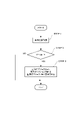
- control for changing the information display position executed by the control unit 25 will be described with reference to FIG.
- control using the speed information of the vehicle 1 as an example of information related to travel of the vehicle 1 will be described.
- the control unit 25 acquires speed information of the vehicle 1 (STEP 1).
- the control unit 25 acquires speed information, for example, at predetermined time intervals.
- the control unit 25 determines whether the vehicle speed V is greater than or equal to the threshold value Vth (STEP 2). If it is determined that the vehicle speed V is less than the threshold value Vth (NO in STEP2), the control unit 25 does not change the display positions of the information I1 and I2.
- the threshold Vth can be appropriately set, for example, based on the speed of the vehicle at which the focal position of the occupant is assumed to be farther than the display distance of the virtual image object Ia. For example, the threshold Vth is 60 km/h.
- the control unit 25 When it is determined that the vehicle speed V is equal to or greater than the threshold value Vth (YES in STEP2), the control unit 25 generates a control signal for displaying the information I1 displayed on the virtual image object Ia on the virtual image object Ib. Output to the unit 24 (STEP 3). As a result, the information I1 displayed on the virtual image object Ia is displayed on the virtual image object Ib, as illustrated in FIG.
- the HUD 20 As described above, in the HUD 20 according to the present embodiment, at least one of the virtual image object Ia and the virtual image object Ib displayed at different distances from the vehicle 1 is displayed on the basis of the information related to the traveling of the vehicle 1. information is displayed on the other of the virtual image object Ia and the virtual image object Ib. As a result, the distance at which information is displayed can be changed according to the running condition of the vehicle 1, so that the visibility of a plurality of pieces of information displayed by the virtual image objects Ia and Ib can be improved.
- the information I1 displayed on the virtual image object Ia located near the vehicle 1 is displayed on the virtual image object Ib located far from the vehicle 1. For example, when the speed of the vehicle 1 increases, the occupant's focal position becomes farther, so it is difficult for the occupant to grasp the information displayed near the vehicle 1 . Therefore, when it is determined that the vehicle 1 is traveling at high speed, the information I1 displayed on the virtual image object Ia is displayed on the virtual image object Ib, thereby displaying the information I1 at a distance (distant) that is easily visible to the occupant. can.
- the information I1 displayed in the virtual image object Ia may be displayed in the virtual image object Ib based on the position information of the vehicle 1.
- the control unit 25 determines that the vehicle 1 has entered an area in which automatic operation is possible such as a motorway (for example, a highway) or an area in which the vehicle 1 is always fast. , outputs a control signal to the image generator 24 for displaying the information I1 displayed on the virtual image object Ia on the virtual image object Ib.
- the information I1 can be displayed at a distance (distant) that is easily visible to the passenger.
- the information I1 displayed in the virtual image object Ia may be displayed in the virtual image object Ib based on the remaining fuel amount information of the vehicle 1. For example, if the information I1 displayed in the virtual image object Ia is information about the remaining amount of fuel, the control unit 25 determines that the amount of remaining fuel is low based on the remaining fuel amount information of the vehicle 1, and the virtual image object Ia is displayed. A control signal is output to the image generator 24 to cause the image object Ib to display the information I1 regarding the remaining amount of fuel displayed in . This can alert the occupant that the remaining amount of fuel is low.
- the information I1 displayed in the virtual image object Ia is displayed in the virtual image object Ib based on the information related to the running of the vehicle 1.
- the information displayed on the virtual image object Ib located far from the vehicle 1 may be displayed on the virtual image object Ia located near the vehicle 1 based on the information related to the traveling of the vehicle 1 .
- the control unit 25 causes the virtual image object Ia to display the information I2 displayed on the virtual image object Ib based on the target object information existing around the vehicle 1 .
- the control unit 25 determines, for example, that the display area of the virtual image object Ib overlaps with the preceding vehicle based on the target object information, the display area of the virtual image object Ib is displayed.
- a control signal for displaying the information I2 on the virtual image object Ia is output to the image generator 24 .
- control unit 25 controls the information displayed on at least one of the virtual image object Ia and the virtual image object Ib based on the information related to the running of the vehicle 1 to the virtual image object Ia and the virtual image object Ib. is displayed on the other side.
- control unit 25 may display the information displayed on at least one of the virtual image objects Ia and Ib on the other of the virtual image objects Ia and Ib based on the instruction of the occupant of the vehicle 1. .
- the control for changing the information display position based on the instruction of the occupant of the vehicle 1 executed by the control unit 25 will be described with reference to FIG.
- the virtual image object Ia displays the speed information I3 of the vehicle 1 and the remaining amount of fuel information I4 of the vehicle 1
- the virtual image object Ib displays information about when the vehicle 1 is running.
- a case where the caution information I5 of the vehicle 1 and the driving support information I6 of the vehicle 1 are displayed will be described.
- the control unit 25 acquires an instruction from the occupant of the vehicle 1 (STEP 11). For example, as exemplified in FIG. 8 , the passenger inputs an instruction regarding display position change via a voice input device 30 arranged in the vehicle 1 . The control unit 25 acquires the command of the passenger directly or indirectly from the voice input device 30 .
- the control unit 25 determines whether the instruction from the passenger is an instruction to change the display position of the vehicle speed information I3 (STEP 12).
- the control unit 25 causes the virtual image object Ib to display the vehicle speed information I3 displayed in the virtual image object Ia. to the image generator 24 (STEP 13).
- the vehicle speed information I3 displayed in the virtual image object Ia is displayed in the virtual image object Ib.
- the vehicle speed information I3 displayed in the virtual image object Ia is displayed in the virtual image object Ib.
- FIG. 9 only the vehicle speed information I3 may be displayed on the virtual image object Ib, and as shown in FIG. Vehicle speed information I3 may be displayed.
- the control unit 25 determines whether the occupant's instruction is an instruction to change the display position of the remaining fuel amount information I4. Make a decision (STEP 14). If it is determined that the instruction from the passenger is not an instruction to change the display position of the remaining amount of fuel information I4 (NO in STEP 14), the control unit 25 does not change the display position of the information displayed on the virtual image objects Ia and Ib. .
- the control unit 25 changes the remaining amount of fuel information I4 displayed in the virtual image object Ia to the virtual image object Ib. is output to the image generator 24 (STEP 15). As a result, as shown in FIG. 11, the remaining amount of fuel information I4 displayed in the virtual image object Ia is displayed in the virtual image object Ib. Note that the virtual image object Ib may display the caution information I5 and the driving support information I6 of the vehicle 1 as well as the remaining amount of fuel information I4.
- the vehicle speed information and the remaining amount of fuel information displayed in the virtual image object Ia located near the vehicle 1 are displayed on the virtual image object Ib located far from the vehicle 1 in accordance with instructions from the occupants of the vehicle 1. Is displayed.
- the occupant can check the information without moving the line of sight much while the vehicle 1 is running. This can improve the visibility of a plurality of pieces of information displayed by the virtual image objects Ia and Ib.
- the control unit 25 controls the speed information I3 and the remaining amount of fuel information I4 displayed on the virtual image object Ib to be displayed on the original virtual image object Ia at the command of the passenger or after a predetermined period of time has elapsed. good too.
- control unit 25 determines that the command from the passenger is an instruction to change the display positions of both the vehicle speed information I3 and the remaining fuel information I4, the control unit 25 displays both the vehicle speed information I3 and the remaining fuel information I4 as virtual image objects. It may be displayed on Ib.
- control unit 25 causes the virtual image object Ib to display the information displayed on the virtual image object Ia based on the instruction of the occupant of the vehicle 1. may be displayed in
- control unit 25 controls information displayed on at least one of the virtual image object Ia and the virtual image object Ib based on the information related to the traveling of the vehicle 1 and the instruction of the occupant of the vehicle 1 to the virtual image object Ia and the virtual image object Ib. It may be displayed on the other side of Ib.
- control for changing the information display position based on the information related to the running of the vehicle 1 and the instruction of the occupant of the vehicle 1 executed by the control unit 25 will be described.
- control using the speed information of the vehicle 1 as an example of information related to travel of the vehicle 1 will be described.
- control unit 25 acquires speed information of the vehicle 1 (STEP 21).
- the control unit 25 acquires speed information, for example, at predetermined time intervals.
- the control unit 25 determines whether the vehicle speed V is greater than or equal to the threshold value Vth (STEP 22). If it is determined that the vehicle speed V is less than the threshold value Vth (NO in STEP 22), the control unit 25 does not change the display positions of the information I1 and I2.
- the threshold Vth can be appropriately set, for example, based on the speed of the vehicle at which the focal position of the occupant is assumed to be farther than the display distance of the virtual image object Ia. For example, the threshold Vth is 60 km/h.
- the control unit 25 determines whether or not an instruction from the occupant of the vehicle 1 has been obtained (STEP 23). For example, the control unit 25 notifies the occupant of the vehicle 1 that the information displayed in the virtual image object Ia will be displayed in the virtual image object Ib. The notification may be displayed on the virtual image object Ib, or may be notified by an audio output device or the like arranged in the vehicle 1 . For example, if the occupant does not wish to change the display position of the information displayed on the virtual image object Ia, the occupant instructs to that effect via the voice input device 30 arranged in the vehicle 1 .
- control unit 25 When it is determined that the command from the passenger of the vehicle 1 has been acquired (YES in STEP 23), the control unit 25 does not change the display positions of the information displayed on the virtual image objects Ia and Ib. If there is no command from the occupant within a predetermined period of time after the display position change notification (NO in STEP 23), the control unit 25 outputs a control signal for displaying the information displayed on the virtual image object Ia on the virtual image object Ib. is output to the image generator 24 (STEP 24).
- the display position of the information displayed in the virtual image object Ia is changed when there is no instruction from the passenger.
- the display position may be changed.
- the positions and ranges of the information displayed on the virtual image objects Ia and Ib are not limited to the forms shown in FIGS. 4, 5, 7, and 9-11.
- the information I1 displayed in the virtual image object Ia is displayed in the virtual image object Ib based on the speed information of the vehicle 1, the position information of the vehicle 1, or the remaining amount of fuel information of the vehicle 1.
- the information I1 displayed in the virtual image object Ia may be displayed in the virtual image object Ib based on the information related to the traveling of the vehicle different from these information.
- the information I2 displayed on the virtual image object Ib is displayed on the virtual image object Ia based on the target object information.
- the information I2 displayed in the virtual image object Ib may be displayed in the virtual image object Ia based on the information related to the running of the vehicle, which is different from the target object information.
- the light for generating the virtual image object Ia and the light for generating the virtual image object Ib are emitted from one image generation unit 24 .
- the HUD 20 includes a plurality of image generators, and can be configured such that the light for generating the virtual image object Ia and the light for generating the virtual image object Ib are emitted from different image generators.
- the instructions of the occupant are acquired via the voice input device 30, but may be acquired via a switch provided on the steering wheel of the vehicle 1 or the like or an imaging device arranged within the vehicle 1.
- the light emitted from the image generator 24 may be configured to enter the concave mirror 26 via an optical component such as a plane mirror.
- the light emitted from the image generation unit 24 is configured to be reflected by the concave mirror 26 and illuminate the windshield 18, but is not limited to this.
- the light reflected by the concave mirror 26 may be directed to a combiner (not shown) provided inside the windshield 18 .
- the combiner consists, for example, of transparent plastic discs. A portion of the light emitted from the image generator 24 of the HUD body 21 to the combiner is reflected toward the viewpoint E of the occupant in the same manner as when the windshield 18 is illuminated with light.
Landscapes
- Engineering & Computer Science (AREA)
- Chemical & Material Sciences (AREA)
- Combustion & Propulsion (AREA)
- Transportation (AREA)
- Mechanical Engineering (AREA)
- Physics & Mathematics (AREA)
- Computer Hardware Design (AREA)
- General Physics & Mathematics (AREA)
- Theoretical Computer Science (AREA)
- Instrument Panels (AREA)
Abstract
Description
車両から異なる距離離れた位置にそれぞれ画像を表示可能に構成された車両用の画像照射装置であって、
前記車両から第一距離だけ離れた位置に表示される第一画像を生成するための第一光と、前記車両から前記第一距離よりも長い第二距離だけ離れた位置に表示される第二画像を生成するための第二光とを出射する画像生成部と、
前記画像生成部を制御する制御部と、
を備えており、
前記制御部は、前記車両の走行に関連する情報および前記車両の乗員の入力指示の少なくとも一方に基づいて、前記第一画像および前記第二画像の少なくとも一方に表示させている情報を、前記第一画像および前記第二画像の他方に表示させる。 An image irradiation device according to one aspect of the present disclosure includes
An image irradiation device for a vehicle configured to display images at positions separated by different distances from the vehicle,
a first light for producing a first image displayed at a first distance from the vehicle; and a second light displayed at a second distance from the vehicle that is greater than the first distance. an image generator that emits a second light for generating an image;
a control unit that controls the image generation unit;
and
The control unit controls information displayed on at least one of the first image and the second image based on at least one of information related to traveling of the vehicle and an input instruction from an occupant of the vehicle to change the information displayed on the first image to the second image. The other of the one image and the second image is displayed.
Claims (6)
- 車両から異なる距離離れた位置にそれぞれ画像を表示可能に構成された車両用の画像照射装置であって、
前記車両から第一距離だけ離れた位置に表示される第一画像を生成するための第一光と、前記車両から前記第一距離よりも長い第二距離だけ離れた位置に表示される第二画像を生成するための第二光とを出射する画像生成部と、
前記画像生成部を制御する制御部と、
を備えており、
前記制御部は、前記車両の走行に関連する情報および前記車両の乗員の入力指示の少なくとも一方に基づいて、前記第一画像および前記第二画像の少なくとも一方に表示させている情報を、前記第一画像および前記第二画像の他方に表示させる、画像照射装置。 An image irradiation device for a vehicle configured to display images at positions separated by different distances from the vehicle,
a first light for producing a first image displayed at a first distance from the vehicle; and a second light displayed at a second distance from the vehicle that is greater than the first distance. an image generator that emits a second light for generating an image;
a control unit that controls the image generation unit;
and
The control unit controls information displayed on at least one of the first image and the second image based on at least one of information related to traveling of the vehicle and an input instruction from an occupant of the vehicle to change the information displayed on the first image to the second image. An image irradiation device that causes the other of the one image and the second image to be displayed. - 前記制御部は、前記車両の走行に関連する情報および前記車両の乗員の入力指示の少なくとも一方に基づいて、前記第一画像に表示されている情報を、前記第二画像に表示させる、請求項1に記載の画像照射装置。 3. The control unit causes the information displayed in the first image to be displayed in the second image based on at least one of information related to travel of the vehicle and an input instruction from an occupant of the vehicle. 2. The image irradiation device according to 1.
- 前記制御部は、前記車両の走行に関連する情報および前記車両の乗員の入力指示の少なくとも一方に基づいて、前記第二画像に表示されている情報を、前記第一画像に表示させる、請求項1または請求項2に記載の画像照射装置。 The control unit causes the information displayed in the second image to be displayed in the first image based on at least one of information related to running of the vehicle and an input instruction from an occupant of the vehicle. 3. The image irradiation device according to claim 1 or 2.
- 前記車両の走行に関連する情報は、前記車両の速度情報である、請求項1から請求項3のいずれか一項に記載の画像照射装置。 The image irradiation device according to any one of claims 1 to 3, wherein the information related to travel of the vehicle is speed information of the vehicle.
- 前記車両の走行に関連する情報は、前記車両の位置情報である、請求項1から請求項3のいずれか一項に記載の画像照射装置。 The image irradiation device according to any one of claims 1 to 3, wherein the information related to travel of the vehicle is position information of the vehicle.
- 前記車両の走行に関連する情報は、前記車両の周辺に存在する対象物情報である、請求項1から請求項3のいずれか一項に記載の画像照射装置。 The image irradiation device according to any one of claims 1 to 3, wherein the information related to running of the vehicle is object information existing around the vehicle.
Priority Applications (3)
| Application Number | Priority Date | Filing Date | Title |
|---|---|---|---|
| CN202280025640.0A CN117098685A (en) | 2021-03-31 | 2022-03-16 | Image irradiation device |
| DE112022001883.6T DE112022001883T5 (en) | 2021-03-31 | 2022-03-16 | Image broadcasting device |
| JP2023510924A JPWO2022209926A1 (en) | 2021-03-31 | 2022-03-16 |
Applications Claiming Priority (4)
| Application Number | Priority Date | Filing Date | Title |
|---|---|---|---|
| JP2021-060975 | 2021-03-31 | ||
| JP2021060975 | 2021-03-31 | ||
| JP2021-114480 | 2021-07-09 | ||
| JP2021114480 | 2021-07-09 |
Publications (1)
| Publication Number | Publication Date |
|---|---|
| WO2022209926A1 true WO2022209926A1 (en) | 2022-10-06 |
Family
ID=83459100
Family Applications (1)
| Application Number | Title | Priority Date | Filing Date |
|---|---|---|---|
| PCT/JP2022/012100 WO2022209926A1 (en) | 2021-03-31 | 2022-03-16 | Image irradiation device |
Country Status (3)
| Country | Link |
|---|---|
| JP (1) | JPWO2022209926A1 (en) |
| DE (1) | DE112022001883T5 (en) |
| WO (1) | WO2022209926A1 (en) |
Citations (3)
| Publication number | Priority date | Publication date | Assignee | Title |
|---|---|---|---|---|
| JP2018116164A (en) * | 2017-01-18 | 2018-07-26 | パナソニックIpマネジメント株式会社 | Display device |
| JP2019147546A (en) * | 2019-03-29 | 2019-09-05 | 株式会社リコー | Information providing device, information providing method, and control program for providing information |
| JP2019166891A (en) * | 2018-03-22 | 2019-10-03 | マクセル株式会社 | Information display device |
Family Cites Families (2)
| Publication number | Priority date | Publication date | Assignee | Title |
|---|---|---|---|---|
| KR102520463B1 (en) | 2014-05-30 | 2023-04-10 | 가부시키가이샤 한도오따이 에네루기 켄큐쇼 | Light-emitting device, display device, and electronic device |
| KR102419333B1 (en) | 2019-10-08 | 2022-07-11 | 신봉근 | Health care system and operating method thereof |
-
2022
- 2022-03-16 WO PCT/JP2022/012100 patent/WO2022209926A1/en active Application Filing
- 2022-03-16 JP JP2023510924A patent/JPWO2022209926A1/ja active Pending
- 2022-03-16 DE DE112022001883.6T patent/DE112022001883T5/en active Pending
Patent Citations (3)
| Publication number | Priority date | Publication date | Assignee | Title |
|---|---|---|---|---|
| JP2018116164A (en) * | 2017-01-18 | 2018-07-26 | パナソニックIpマネジメント株式会社 | Display device |
| JP2019166891A (en) * | 2018-03-22 | 2019-10-03 | マクセル株式会社 | Information display device |
| JP2019147546A (en) * | 2019-03-29 | 2019-09-05 | 株式会社リコー | Information providing device, information providing method, and control program for providing information |
Also Published As
| Publication number | Publication date |
|---|---|
| JPWO2022209926A1 (en) | 2022-10-06 |
| DE112022001883T5 (en) | 2024-01-18 |
Similar Documents
| Publication | Publication Date | Title |
|---|---|---|
| JP6699675B2 (en) | Information provision device | |
| US10551619B2 (en) | Information processing system and information display apparatus | |
| US10732408B2 (en) | Projection type display device and projection display method | |
| JP6271006B2 (en) | Virtual image display device | |
| JP7254832B2 (en) | HEAD-UP DISPLAY, VEHICLE DISPLAY SYSTEM, AND VEHICLE DISPLAY METHOD | |
| JP6499632B2 (en) | Vehicle lighting | |
| US9946078B2 (en) | Head-up display device | |
| JP6361794B2 (en) | Vehicle information projection system | |
| JP2014213763A (en) | Vehicle information projection system | |
| JP2013032087A (en) | Vehicle head-up display | |
| JP6516151B2 (en) | INFORMATION PROVIDING DEVICE, INFORMATION PROVIDING METHOD, AND INFORMATION PROVIDING CONTROL PROGRAM | |
| WO2016158333A1 (en) | Head-up display | |
| JP7241081B2 (en) | Vehicle display system and vehicle | |
| JPWO2018056058A1 (en) | Projection display device, projection display method, and projection display program | |
| WO2021065617A1 (en) | Vehicular display system and vehicle | |
| JP7478160B2 (en) | Head-up displays and image display systems | |
| JP2021529332A (en) | Head-up display device and its display method | |
| JP7295863B2 (en) | Vehicle display system and vehicle | |
| JP2023175794A (en) | Head-up display | |
| WO2022209926A1 (en) | Image irradiation device | |
| WO2020189636A1 (en) | Information providing system, moving body, information providing method, and information providing program | |
| CN117098685A (en) | Image irradiation device | |
| JP2017105245A (en) | Head-up display device | |
| US20200049983A1 (en) | Display device, display control method, and storage medium | |
| WO2023120130A1 (en) | Image projection device |
Legal Events
| Date | Code | Title | Description |
|---|---|---|---|
| 121 | Ep: the epo has been informed by wipo that ep was designated in this application |
Ref document number: 22780146 Country of ref document: EP Kind code of ref document: A1 |
|
| ENP | Entry into the national phase |
Ref document number: 2023510924 Country of ref document: JP Kind code of ref document: A |
|
| WWE | Wipo information: entry into national phase |
Ref document number: 202280025640.0 Country of ref document: CN |
|
| WWE | Wipo information: entry into national phase |
Ref document number: 112022001883 Country of ref document: DE |
|
| 122 | Ep: pct application non-entry in european phase |
Ref document number: 22780146 Country of ref document: EP Kind code of ref document: A1 |