WO2022202021A1 - Control apparatus, control method, and control system for force-sense device - Google Patents
Control apparatus, control method, and control system for force-sense device Download PDFInfo
- Publication number
- WO2022202021A1 WO2022202021A1 PCT/JP2022/006708 JP2022006708W WO2022202021A1 WO 2022202021 A1 WO2022202021 A1 WO 2022202021A1 JP 2022006708 W JP2022006708 W JP 2022006708W WO 2022202021 A1 WO2022202021 A1 WO 2022202021A1
- Authority
- WO
- WIPO (PCT)
- Prior art keywords
- fingertip
- virtual object
- control
- control unit
- unit
- Prior art date
Links
- 238000000034 method Methods 0.000 title claims abstract description 25
- 230000009471 action Effects 0.000 claims abstract description 39
- 230000035807 sensation Effects 0.000 claims abstract description 7
- 238000012545 processing Methods 0.000 claims description 55
- 238000012937 correction Methods 0.000 claims description 37
- 230000008569 process Effects 0.000 claims description 16
- 230000003313 weakening effect Effects 0.000 claims description 5
- 230000001953 sensory effect Effects 0.000 claims 1
- 238000010586 diagram Methods 0.000 description 37
- 238000004891 communication Methods 0.000 description 9
- 230000006870 function Effects 0.000 description 7
- 230000007423 decrease Effects 0.000 description 5
- 238000001514 detection method Methods 0.000 description 5
- 230000003993 interaction Effects 0.000 description 4
- 230000007246 mechanism Effects 0.000 description 4
- 230000000694 effects Effects 0.000 description 3
- 238000005516 engineering process Methods 0.000 description 3
- 210000003128 head Anatomy 0.000 description 3
- 241000251468 Actinopterygii Species 0.000 description 2
- 238000005259 measurement Methods 0.000 description 2
- 230000035515 penetration Effects 0.000 description 2
- 230000000638 stimulation Effects 0.000 description 2
- 229910000906 Bronze Inorganic materials 0.000 description 1
- OAICVXFJPJFONN-UHFFFAOYSA-N Phosphorus Chemical compound [P] OAICVXFJPJFONN-UHFFFAOYSA-N 0.000 description 1
- 229910000639 Spring steel Inorganic materials 0.000 description 1
- 230000001133 acceleration Effects 0.000 description 1
- 230000001154 acute effect Effects 0.000 description 1
- 238000007792 addition Methods 0.000 description 1
- 230000003190 augmentative effect Effects 0.000 description 1
- 239000010974 bronze Substances 0.000 description 1
- 230000008859 change Effects 0.000 description 1
- KUNSUQLRTQLHQQ-UHFFFAOYSA-N copper tin Chemical compound [Cu].[Sn] KUNSUQLRTQLHQQ-UHFFFAOYSA-N 0.000 description 1
- 238000012217 deletion Methods 0.000 description 1
- 230000037430 deletion Effects 0.000 description 1
- 230000000994 depressogenic effect Effects 0.000 description 1
- 210000005069 ears Anatomy 0.000 description 1
- 239000013013 elastic material Substances 0.000 description 1
- 229920006351 engineering plastic Polymers 0.000 description 1
- 230000005057 finger movement Effects 0.000 description 1
- 238000007654 immersion Methods 0.000 description 1
- 238000012986 modification Methods 0.000 description 1
- 230000004048 modification Effects 0.000 description 1
- 230000003287 optical effect Effects 0.000 description 1
- 230000002093 peripheral effect Effects 0.000 description 1
- 238000009877 rendering Methods 0.000 description 1
- 239000004065 semiconductor Substances 0.000 description 1
- 230000015541 sensory perception of touch Effects 0.000 description 1
- 238000000926 separation method Methods 0.000 description 1
- 230000000007 visual effect Effects 0.000 description 1
Images


Classifications
-
- G—PHYSICS
- G06—COMPUTING; CALCULATING OR COUNTING
- G06F—ELECTRIC DIGITAL DATA PROCESSING
- G06F3/00—Input arrangements for transferring data to be processed into a form capable of being handled by the computer; Output arrangements for transferring data from processing unit to output unit, e.g. interface arrangements
- G06F3/01—Input arrangements or combined input and output arrangements for interaction between user and computer
Definitions
- the present disclosure relates to a control device, control method, and control system for haptic devices.
- the present disclosure provides a control device, control method, and system for a haptic device capable of giving a more natural haptic sensation.
- a position information acquisition unit that acquires position information on a surface of a virtual object and position information on a fingertip; a control unit that controls the position of an action unit that applies force to the fingertip based on the position information; When the fingertip is pushed from the surface of the virtual object, the control unit applies a first force to the action unit in a first direction away from the surface of the virtual object when the fingertip is returned from the pushed position.
- a controller for a haptic device is provided that weakens a second force applied in a second direction opposite to the first direction.
- the control unit may fix the position of the action unit so that the fingertip does not move when the position of the surface of the virtual object and the position of the fingertip are in a predetermined relationship.
- the control unit may release the fixation when the fingertip moves in the first direction.
- the action part is fixed to the manipulator,
- the controller may control voltage of a motor that drives the manipulator.
- the first direction may be the normal direction of the surface of the virtual object.
- the control section may control a first voltage of a motor that applies force in the first direction and a second voltage of a motor that applies force in the second direction to the action section.
- the control unit may perform control to set the second voltage to 0 or bring it closer to 0 when releasing the fixation.
- the control unit may perform control to suppress the second voltage through correction processing for weakening the second voltage.
- the control unit may perform feedback processing for moving the fingertip to a target position based on the surface of the virtual object, and may perform the correction processing after the feedback processing is completed.
- the control unit may perform the correction process after the virtual object is a movable object and the virtual object stops in conjunction with the movement of the fingertip.
- the control unit may stop the correction process when the virtual object itself moves.
- the control unit may change the degree of correction for weakening the second voltage according to the contact time between the surface of the virtual object and the fingertip.
- the control unit may maintain the predetermined second voltage when the surface of the virtual object has an attribute indicating viscosity.
- the control step when the fingertip is pushed from the surface of the virtual object, the first force is applied to the action portion in the first direction away from the surface of the virtual object when the fingertip is returned from the pushed position.
- a method of controlling a haptic device is provided that weakens a second force applied in a second direction opposite to the direction.
- an image processing device that displays a virtual object in a virtual space corresponding to the real space; a control device that controls a haptic device that gives a haptic sensation to a user's fingertip;
- the control device is a position information acquisition unit that acquires position information on the surface of the R object and position information on the fingertip; a control unit that controls the position of an action unit that applies force to the fingertip based on the position information, and the control unit is configured to move the fingertip in a first direction away from the surface of the virtual object when the fingertip is pushed through the surface of the virtual object.
- a control system for a haptic device wherein a second force applied in a second direction opposite to the first direction when returning the fingertip from the pressed position is weaker than the first force applied to the action portion in provided.
- FIG. 2 is a diagram showing an appearance example of a head-mounted display according to the present embodiment;
- 2 is a diagram showing the internal circuit configuration of the image processing apparatus;
- FIG. 2 is a diagram showing the configuration of functional blocks of an image processing apparatus;
- FIG. The figure which shows the structural example of a haptic device.
- fixed part typically.
- FIG. 2 is a block diagram showing a configuration example of a control device for the haptic device;
- FIG. 9 is a diagram showing an example of controlling the motor voltage of the actuator in the right diagram of FIG. 8;
- FIG. 9 is a diagram showing an example of controlling the motor voltage of the actuator in the right diagram of FIG. 8;
- FIG. 10 is a diagram showing an example of control of the control device of the haptic device when there is an angle;
- FIG. 5 is a diagram showing an example of controlling the motor voltage of the actuator during feedback control;
- FIG. 4 is a diagram showing an example of control of a moving object by a control device for a haptic device;
- FIG. 4 is a diagram schematically showing a case where a virtual object moves by itself;
- FIG. 5 is a diagram showing an example of motor voltage control during feedback control when a virtual object has viscosity;
- FIG. 10 is a diagram showing a control example of changing correction processing according to contact time between a virtual object and a finger; The figure which shows an example of control of the driving force control part at the time of pushing in without releasing a finger
- 4 is a flow chart showing an example of processing of the control device of the haptic device.
- control system may have components and functions that are not illustrated or described. The following description does not exclude components or features not shown or described.
- FIG. 1 is a diagram showing an appearance example of a head-mounted display according to the present embodiment.
- the head mounted display 100 is composed of an output mechanism section 102 and a mounting mechanism section 104 .
- the mounting mechanism section 104 includes a mounting band 106 that is worn by the user so as to go around the head and fix the device.
- the output mechanism unit 102 includes a housing 108 shaped to cover the left and right eyes when the user wears the head-mounted display 100, and has a display panel inside so as to face the eyes when the head-mounted display 100 is worn.
- the housing 108 may further include a lens positioned between the display panel and the user's eyes when the head-mounted display 100 is worn to magnify the image.
- Stereoscopic vision may be realized by displaying a stereo image corresponding to binocular parallax in each region obtained by dividing the display panel into left and right.
- the head mounted display 100 may further include speakers and earphones at positions corresponding to the ears of the user when worn.
- the head-mounted display 100 includes a stereo camera 110 on the front surface of the housing 108, and captures moving images of the surrounding real space in a field of view corresponding to the line of sight of the user.
- the head mounted display 100 may include any one of various sensors such as an acceleration sensor, a gyro sensor, and a geomagnetic sensor inside or outside the housing 108 for deriving the movement, attitude, position, etc. of the head mounted display 100. .
- FIG. 2 is a diagram showing a configuration example of a haptic device control system 1 to which the present embodiment can be applied.
- the control system 1 includes an image processing device 10 , a haptic device controller 70 , a head mounted display 100 , a microphone 130 , a camera 132 , a haptic device 134 , and a server 200 .
- the head mounted display 100 is connected to the image processing device 10 by wireless communication. However, a wired connection such as a USB may be used.
- the control device 70 of the haptic device, the microphone 130 and the camera 132 are also connected to the image processing device 10 by wire or wirelessly.
- the image processing device 10 is connected to the server 200 via the network 8.
- the server 200 transmits electronic content data such as moving images and net games to the image processing apparatus 10, for example.
- the image processing apparatus 10 performs necessary processing on the content data transmitted from the server 200 and transmits the processed data to the head mounted display 100 .
- the image processing apparatus 10 may internally process electronic content to generate image and audio data, and transmit the data to the head mounted display 100 .
- the image processing device 10 may be provided inside the head mounted display 100 .
- a device for displaying an image of content is not limited to a head-mounted display, and may be a flat-panel display such as a television receiver, a portable terminal, a projector, or the like.
- the image processing device 10 continuously acquires the position and orientation of the head of the user wearing it, based on the measurement values of the motion sensor built into the head-mounted display 100, for example. , to generate a display image with a corresponding field of view.
- a representative example of such a display technology is virtual reality (VR), which represents an image corresponding to the user's field of view, out of a three-dimensional space representing a virtual world and a captured panoramic image.
- VR virtual reality
- the image processing device 10 draws a virtual object (also referred to as a virtual object or a VR object) at an appropriate position in the real-time image captured by the stereo camera 110, thereby performing augmented reality (AR).
- a virtual object also referred to as a virtual object or a VR object
- AR augmented reality
- the image processing device 10 may reproduce general movies, moving images, etc. with a fixed field of view regardless of the movement of the user's head. Since the display form of these electronic contents is a general one, detailed description thereof will be omitted.
- the microphone 130 supplies the voice uttered by the user to the image processing device 10 as a signal.
- the camera 132 supplies the image processing apparatus 10 with real-time data of a moving image of a user's hand or the like.
- the image processing apparatus 10 acquires the user's hand movements and gestures based on the captured image, and detects the content of the operation. Then, a process corresponding to the content of the operation is executed.
- the camera 132 may be a visible light camera, a stereo camera, a multispectral camera, a depth camera, or the like, and the physical values to be detected are not particularly limited as long as the position and orientation of the subject can be obtained for each frame. Moreover, one of them may be introduced, or two or more of them may be introduced in combination.
- the haptic device 134 is a device that transmits tactile and haptic information such as vibration when worn by the user.
- the haptic device control device 70 transmits the pseudo feel to the fingertip via the haptic device 134 while the user is touching the virtual object with the finger. Details of the haptic device 134 will be described later. Also, the control device 70 of the haptic device may be simply referred to as the control device 70 .
- the shapes of the microphone 130, the camera 132, and the haptic device 134 are not limited to those illustrated.
- the microphone 130 may be part of the head mounted display 100 or may be provided integrally with the camera 132 .
- a motion sensor such as a virtual glove worn by the user may be introduced to detect finger movements.
- the haptic device 134 may be attached to the virtual glove.
- the function of camera 132 may be performed by stereo camera 110 of head mounted display 100 .
- FIG. 3 is a diagram showing the internal circuit configuration of the image processing apparatus 10.
- the image processing device 10 includes a CPU (Central Processing Unit) 23 , a GPU (Graphics Processing Unit) 24 and a main memory 26 . These units are interconnected via a bus 30 . An input/output interface 28 is also connected to the bus 30 .
- CPU Central Processing Unit
- GPU Graphics Processing Unit
- the input/output interface 28 includes a peripheral device interface such as USB and IEEE 1394, a wired or wireless LAN network interface, a communication unit 32 that establishes communication with the server 200 and the head mounted display 100, a hard disk drive, a nonvolatile memory, and the like.
- a recording medium driving unit 40 for driving a removable recording medium such as a recording medium is connected.
- the CPU 23 controls the entire image processing apparatus 10 by executing the operating system stored in the storage unit 34 .
- the CPU 23 also executes various programs read from a removable recording medium and loaded into the main memory 26 or downloaded via the communication section 32 .
- the GPU 24 has a function of a geometry engine and a function of a rendering processor, performs drawing processing according to a drawing command from the CPU 23 , and outputs the result to the output unit 36 .
- the main memory 26 is composed of a RAM (Random Access Memory) and stores programs and data necessary for processing. Note that the character information input in the present embodiment is stored in the main memory 26 by a user operation or at a predetermined timing.
- FIG. 4 is a diagram showing the configuration of functional blocks of the image processing apparatus 10. As shown in FIG. Each functional block shown in the figure can be realized by CPU, GPU, memory, etc. in terms of hardware. It is realized by a program that exhibits various functions such as a communication function. Therefore, those skilled in the art will understand that these functional blocks can be realized in various forms by hardware only, software only, or a combination thereof, and are not limited to either one.
- the image processing apparatus 10 includes a speech recognition unit 62 that recognizes a user's voice and converts it into character information, a motion recognition unit 64 that recognizes a user's motion or gesture, an image generation unit 66 that generates a display image, and a display image data.
- An output unit 68 that outputs to the head-mounted display 100, an object control unit 50 that realizes interaction with the user by arranging virtual objects in a three-dimensional virtual space, and a communication unit that communicates with other devices via the network 8. 60.
- the voice recognition unit 62 acquires a voice signal uttered by the user from the microphone 130 and converts it into characters. Any of various practically used techniques may be applied to the speech recognition processing performed here.
- the action recognition unit 64 acquires an image of the user's hand or the like from at least one of the camera 132 and the head mounted display 100 .
- the motion recognition unit 64 acquires information about the movement of the fingertip from the encoder of the haptic device 134 or the like via the control device 70, and recognizes the motion of the user's hand.
- the action recognition unit 64 acquires measurement values of sensors worn by the user. More details will be described later.
- the image generation unit 66 generates an image of content to be displayed on the head mounted display 100 .
- the image generating unit 66 decodes and expands the compression-encoded moving image data acquired by the communication unit 60 and reproduces the decoded data.
- the image generator 66 may itself process the electronic game and render the image.
- the image generator 66 may generate the VR or AR image described above.
- the image generation unit 66 further projects the virtual object constructed by the object control unit 50 onto a view screen corresponding to the field of view of the head mounted display 100, thereby including the virtual object in the display image.
- the virtual objects arranged in this virtual space by the object control unit 50 can be projected onto the view screen together with the objects of the content.
- the output unit 68 outputs the display image data generated by the image generation unit 66 to the head mounted display 100 .
- the object control unit 50 realizes virtual interaction according to the user's actions, and changes the virtual object according to the result. Therefore, the object control unit 50 also displays the image of the user's hand in the virtual space to visually express the interaction of the virtual object.
- the object control unit 50 has an object generation unit 52 and an interaction processing unit 54.
- the object generation unit 52 acquires character information obtained by converting the voice by the voice recognition unit 62 .
- the image of the hand may be a live-action image captured by the stereo camera 110 of the head-mounted display 100 or an image drawn by computer graphics, as long as the actual movement of the user's hand can be reflected in real time.
- the object generation unit 52 corrects the touched virtual object according to the position of the user's fingertip by the action recognition unit 64.
- the object generation unit 52 detects that the user has touched the virtual object. Then, the touched virtual object is corrected according to the motion of pushing or pinching the virtual object.
- the content of correction may be switched according to the combination of fingers pinching the virtual object. Further, the content of correction may be switched depending on whether the virtual object is touched with the pad of the finger or the back of the finger.
- the communication unit 60 establishes communication with other devices such as the server 200 via the network 8 , acquires content data, and supplies it to the image generation unit 66 .
- the control device 70 controls the haptic device 134 to give the user tactile stimulation corresponding to the user's movement with respect to the virtual object. For example, as described above, the user's touching of the virtual object is haptically produced. The details of the haptic device control device 70 will be described later.
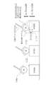
- FIG. 5A is a diagram showing a configuration example of the haptic device 134.
- the haptic device 134 has a finger fixing portion 134a, a small manipulator 134b, an actuator 134c, an angle detection sensor 134d, and a base 134e.
- FIG. 5A shows a state in which the small manipulator 134b is bent.
- FIG. 5B is a diagram showing a state in which the small manipulator 134b is extended.
- FIG. 6 is a diagram schematically showing the finger fixing portion 134a.
- the finger fixing portion 134a is a portion for fixing a human finger.
- they are made of elastic materials such as engineering plastics, phosphor bronze, and spring steel. Note that the finger fixing portion 134 according to this embodiment corresponds to the action portion.
- the small manipulator 134b consists of a set of an actuator 134c and an angle detection sensor 134d.
- the actuator 134c and the angle detection sensor 134d are arranged inside the base 134e, for example.
- Actuator 134c is, for example, a DC electric motor.
- the angle detection sensor 134d is, for example, an encoder.
- the end portion of the small manipulator 134b is connected to the finger fixing portion 134a and the base 134e.
- the base 134e is fixed to the back of a human hand, for example. In this case, it is fixed to the back of the hand by means of a belt, a restraint, or the like (not shown). Alternatively, the base 134e may be fixed to the human hand by fixing the base 134e to a glove and wearing the glove.
- the small manipulator 134b can apply, for example, a 6-axis force to the finger fixing portion 134.
- the haptic device 134 fixes a finger to the finger fixing portion 134a and drives the small manipulator 2, it can apply force in, for example, six axial directions to the human fingertip according to the number of active joints.
- the case of one degree of freedom will be described in order to simplify the description, but the present invention is not limited to this.
- any device may be used as long as it can give a fingertip a tactile sense, force sense, or the like. It may also be combined with other haptic devices such as electrical stimulation, gyroscopic effect, pneumatic pressure, and pressure.
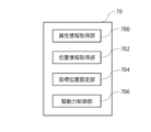
- FIG. 7 is a block diagram showing a configuration example of the control device 70 of the haptic device.
- the haptic device control device 70 includes an attribute information acquisition section 700 , a position information acquisition section 702 , a target position setting section 704 , and a driving force control section 706 .
- the control device 70 includes a CPU (Central Processing Unit) and a main memory (not shown). The processing functions of each unit are configured by executing programs stored in the main memory.
- CPU Central Processing Unit
- the attribute information acquisition unit 700 acquires attributes of virtual objects.
- the attribute information acquisition unit 700 acquires information such as fixed objects, movable objects, hardness, adhesiveness, etc. from the object generation unit 52 as attributes of virtual objects.
- the position information acquisition unit 702 acquires the position information of the virtual object from the object generation unit 52, acquires the position of the user's fingertip from the action recognition unit 64, and acquires the position information from the angle detection sensor 134d (see FIGS. 5A and 5B) to the small manipulator 134b. Get the status information of
- the target position setting unit 704 sets the target position of the user's fingertip based on the position information of the virtual object acquired from the object generation unit 52 . For example, if the attributes of the virtual object are fixed and high hardness, the target position is the surface of the virtual object. On the other hand, when the attribute of the virtual object is a movable object or an object with low hardness, the target position setting unit 704 sets the target position based on the deformation information and movement information of the virtual object generated by the object generation unit 52. set.
- the driving force control unit 706 Based on the position of the user's fingertip acquired from the motion recognition unit 64, the driving force control unit 706 performs feedback control so that the position of the user's fingertip becomes the target position. More specifically, the driving force control unit 706 controls the actuator 134c (see FIGS. 5A and 5B), and performs position control of the small manipulator 134b so that the position of the user's fingertip becomes the target position. Note that the driving force control unit 706 according to this embodiment corresponds to the control unit.
- FIG. 8 is a diagram showing an example of control by the driving force control section 706.
- FIG. The virtual object in FIG. 8 is a fixed object with high hardness.
- the left diagram shows the state before the user's fingertip touches the virtual object
- the middle diagram shows the state at the moment when the user's fingertip touches the virtual object
- the right diagram shows the state where the user's fingertip touches the virtual object. It shows a state of sinking.
- the target position setting unit 704 sets the surface of the virtual object as the target position. Accordingly, the driving force control unit 706 controls the position of the small manipulator 134b based on the position of the user's fingertip acquired from the action recognition unit 64 so that the user's fingertip is positioned on the surface of the virtual object.
- the driving force control unit 706 performs control to lock the small manipulator 134b at the moment the user's fingertip touches the virtual object. As a result, the user's finger does not move.
- the driving force control unit 706 performs control to lift the small manipulator 134b so that the user's finger is positioned at the target position.
- the mold manipulator 134b is controlled so that the user's finger is positioned on the plane of the virtual object, which is the target position.
- the driving force control unit 706 applies more force than the first force applied to the finger fixing unit 134a in the positive direction (first direction) away from the surface of the virtual object.
- the second force applied in the negative direction (second direction) opposite to the first direction is weakened when the fingertip is retracted.
- the driving force control unit 706 controls the actuator 134c (Fig. 5A , B) are not applied to the motor. That is, based on the position of the user's fingertip acquired from the motion recognition unit 64, the driving force control unit 706 controls so that the force of the small manipulator 134b is not applied in the first direction of the normal vector in which the amount of penetration L10 decreases. do.
- the positive potential Vp refers to the actuator 134c (see FIGS. 5A and 5B) that applies a force in the normal direction (first direction) to the finger fixing portion 134a of the small manipulator 134b when the embedding amount L10 increases. reference) means the motor voltage potential.
- the negative potential Vn here refers to the actuator 134c (see FIG. 5A, B) means the motor voltage potential.
- FIG. 9 is a diagram showing an example of controlling the motor voltage of the actuator 134c (see FIGS. 5A and 5B) in the right diagram of FIG.
- the vertical axis indicates the magnitude of the applied voltage, and the horizontal axis indicates time.
- the driving force control section 706 sets the negative potential Vn to zero.
- the small manipulator 134b is unlocked in the first direction of the normal vector in which the amount of penetration L10 decreases, and the force of the small manipulator 134b is not applied, so that the user's discomfort can be suppressed.
- FIG. 10 is a diagram showing an example of control by the haptic device control device 70 when there is an angle ⁇ between the positive direction of the haptic device 134 and the normal vector of the surface of the virtual object.
- FIG. 11 is a diagram showing an example of controlling the motor voltage of the actuator 134c (see FIGS. 5A and 5B) during feedback control.
- the vertical axis indicates the magnitude of the applied voltage, and the horizontal axis indicates time.
- the application of the negative potential Vn is continued while the driving force control unit 706 is performing feedback control with respect to the target position. Then, the negative potential Vn is set to 0 after the feedback control ends. In this embodiment, suppressing the negative potential Vn is referred to as correction. If the negative potential Vn is corrected before the feedback control ends, the overshoot in the negative direction cannot be suppressed, and control to the target position becomes difficult.
- the driving force control unit 706 according to the present embodiment corrects the negative potential Vn after the feedback control ends, so that the position of the fingertip can be controlled to the target position.
- FIG. 12 is a diagram showing an example of the control of the moving object by the control device 70 of the haptic device.
- the virtual object in FIG. 12 is a moving object with high hardness.
- the left diagram shows the state before the user's fingertip touches the virtual object
- the middle diagram shows the state at the moment the user's fingertip touches the virtual object
- the right diagram shows the state where the user's fingertip pushes the virtual object.
- the driving force control unit 706 performs control to lock the small manipulator 134b at the moment when the user's fingertip touches the virtual object. As a result, the user's finger does not move.
- the voltage Vp may be corrected according to the easiness of movement of the moving object so that the moving object can be pushed with a finger.
- the object generator 52 moves the virtual object according to the amount of movement of the user's fingertip, as shown in the right figure.
- the driving force control unit 706 gives priority to the position control when the user's fingertip is moving while pushing the virtual object, and stops correcting the negative potential Vn. As a result, overshoot is suppressed, and unnatural separation between the fingertip and the virtual object is suppressed. In this way, when the virtual object is pushed and moved, it is unlikely that the finger will be lifted from the object. Therefore, it is possible to suppress the user's sense of incongruity and maintain control accuracy.
- FIG. 13 is a diagram schematically showing a case where a virtual object moves by itself.
- the virtual object is, for example, a fish and moves by itself
- the application of correction to the negative potential Vn is stopped.
- the driving force control unit 706 disables the correction control when contacting a virtual object that moves by itself. As a result, it is possible to suppress the uncomfortable feeling of being restricted in one direction.
- FIG. 14 is a diagram showing an example of controlling the motor voltage of the actuator 134c (see FIGS. 5A and 5B) during feedback control when the virtual object has viscosity.
- the vertical axis indicates the magnitude of the applied voltage, and the horizontal axis indicates time.
- the application of the negative potential Vn is continued while the driving force control unit 706 is performing feedback control with respect to the target position.
- the driving force control unit 706 maintains the minute negative potential Vn even after the feedback control ends. As a result, when the virtual object is viscous, it is possible to maintain the feel of the finger sticking to the virtual object.
- FIG. 15 is a diagram showing a control example of changing the correction process to the negative potential Vn according to the contact time between the virtual object and the finger.
- the vertical axis indicates whether the correction process is enabled or disabled, and the horizontal axis indicates the contact time between the virtual object and the finger.
- the driving force control unit 706 validates the correction processing. That is, the driving force control unit 706 sets the negative potential Vn to 0 when the contact time between the virtual object and the finger is shorter than the predetermined value T1. As a result, a sense of incongruity is suppressed in the action of instantly releasing the finger from the virtual object, such as tap processing.
- the contact time is longer than the predetermined value T1
- interference between the virtual object and the finger occurs, so the degree of correction is increased according to the time of contact. This makes it possible to reduce discomfort while enabling feedback control for aligning the finger with the surface position of the virtual object.
- the drive force control unit 706 needs drive control to align the finger with the surface position of the virtual object. Therefore, the driving force control unit 706 disables the correction process and gives priority to the feedback control. This makes it possible to suppress overshoot and the like.
- the driving force control unit 706 terminates the drive control for aligning the finger with the surface position of the virtual object, so the correction process is strengthened as time elapses. As a result, discomfort can be reduced as time elapses. Then, when the contact time becomes longer than the predetermined value T4, the negative potential Vn is set to 0 to make the correction process completely effective. In this way, by changing the correction processing for the negative potential Vn according to the contact time between the virtual object and the finger, it is possible to improve the accuracy of position control and reduce discomfort.
- FIG. 16 is a diagram showing an example of the control of the driving force control unit 706 when the finger is pushed in without being released after performing the action of releasing the finger from the virtual object.
- Fig. A shows the state at the moment when the user's fingertip touches the virtual object
- Fig. B shows the state where the user's fingertip is embedded in the surface of the virtual object
- Fig. C shows the state from the state shown in Fig. B.
- FIG. D shows a state in which the fingertip of the user is pushed into the virtual object again without releasing the finger from the state shown in FIG. C
- FIG. E shows a state in which the finger is released from the state shown in FIG. It is a diagram.
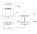
- FIG. 17 is a flowchart showing a processing example of the control device 70 of the haptic device. Here, a case will be described where the finger touches the virtual object and the finger is pressed again.
- the attribute information acquisition unit 700 acquires the attribute of the virtual object, and the driving force control unit 706 sets the correction coefficient of the negative potential Vn based on the attribute (step S100).
- the driving force control unit 706 determines whether or not re-pressing has occurred based on the position of the user's fingertip obtained from the motion recognition unit 64 (step S102).
- the driving force control unit 706 changes the direction of the force of the small manipulator 134b according to the normal to the surface of the virtual object. Then, the correction coefficient is recalculated (step S104). Then, the motor voltage of the actuator 134c (see FIGS. 5A and 5B) is controlled in the direction in which the amount of deviation decreases with the value of the negative potential Vn based on the correction coefficient (step S106), and the process ends.
- driving force control unit 706 determines that re-pressing has not occurred (N in step S102)
- driving force control unit 706 does not recalculate the correction coefficient, and maintains negative potential Vn based on the correction coefficient. is used to control the motor voltage of the actuator 134c (see FIGS. 5A and 5B) in the direction in which the amount of deviation decreases (step S108), and the process ends.
- the position information acquisition unit 702 acquires the position information on the surface of the virtual object and the position information on the fingertip, and the driving force control unit 706 drives the fingertip based on these position information.
- Position control of the finger fixing portion 134a to which force is applied is performed.
- the driving force control unit 706 applies more force than the first force applied to the finger fixing unit 134a in the positive direction (first direction) away from the surface of the virtual object when the fingertip is pushed in from the surface of the virtual object.
- the second force applied in the negative direction (second direction) which is the opposite direction to the positive direction, is weakened when the fingertip is returned from the position.
- This technology can be configured as follows.
- a position information acquisition unit that acquires position information on the surface of the virtual object and position information on the fingertip; a control unit that controls the position of an action unit that applies force to the fingertip based on the position information;
- the control unit applies a first force to the action unit in a first direction away from the surface of the virtual object when the fingertip is returned from the pushed position.
- a control device for a haptic device that weakens a second force applied in a second direction opposite to the first direction.
- control unit fixes the position of the action unit so that the fingertip does not move when the position of the surface of the virtual object and the position of the fingertip are in a predetermined relationship;
- a controller for the described haptic device
- the action portion is fixed to the manipulator;
- the control unit controls a first voltage of a motor that applies force in the first direction to the action unit and a second voltage of the motor that applies force in the second direction.
- the control device according to the above.
- the control unit performs feedback processing for moving the fingertip to a target position based on the surface of the virtual object, and performs the correction processing after the feedback processing is completed. ).
- control device (13) The control device according to (8), wherein the control unit maintains the predetermined second voltage when the surface of the virtual object has an attribute indicating viscosity.
- a control method for a haptic device that weakens a second force applied in a second direction opposite to the direction.
- an image processing device that displays a virtual object in a virtual space corresponding to the real space; a control device that controls a haptic device that gives a haptic sensation to a user's fingertip;
- the control device is a position information acquisition unit that acquires position information on the surface of the R object and position information on the fingertip; a control unit that controls the position of an action unit that applies force to the fingertip based on the position information, and the control unit is configured to move the fingertip in a first direction away from the surface of the virtual object when the fingertip is pushed through the surface of the virtual object.
- a control system for a haptic device which weakens a second force applied in a second direction opposite to the first direction when the fingertip is returned from the pressed position more than the first force applied to the action portion.
- control system for haptic device 70: control device for haptic device, 134: haptic device, 134a: finger fixing unit, 134b: small manipulator, 134c: actuator, 702: position information acquisition unit, 706: driving force control unit.
Landscapes
- Engineering & Computer Science (AREA)
- General Engineering & Computer Science (AREA)
- Theoretical Computer Science (AREA)
- Human Computer Interaction (AREA)
- Physics & Mathematics (AREA)
- General Physics & Mathematics (AREA)
- User Interface Of Digital Computer (AREA)
Abstract
Description
前記位置情報に基づき、前記指先に力を加える作用部の位置制御を行う制御部と、を備え、
前記制御部は、前記仮想物体の面より前記指先を押し込む場合に前記仮想物体の面から離れる第1方向に前記作用部に加える第1力よりも、前記押し込んだ位置から前記指先を戻す場合に前記第1方向と反対方向である第2方向に加える第2力を弱くする、力覚デバイスの制御装置が提供される。 In order to solve the above problems, according to the present disclosure, a position information acquisition unit that acquires position information on a surface of a virtual object and position information on a fingertip;
a control unit that controls the position of an action unit that applies force to the fingertip based on the position information;
When the fingertip is pushed from the surface of the virtual object, the control unit applies a first force to the action unit in a first direction away from the surface of the virtual object when the fingertip is returned from the pushed position. A controller for a haptic device is provided that weakens a second force applied in a second direction opposite to the first direction.
前記制御部は、前記マニピュレータを駆動するモータの電圧を制御してもよい。 The action part is fixed to the manipulator,
The controller may control voltage of a motor that drives the manipulator.
前記位置情報に基づき、前記指先に力を加える作用部の位置制御を行う制御工程と、を備え、
前記制御工程は、仮想物体の面より指先を押し込む場合に前記仮想物体の面から離れる第1方向に前記作用部に加える第1力よりも、前記押し込んだ位置から指先を戻す場合に前記第1方向と反対方向である第2方向に加える第2力を弱くする、力覚デバイスの制御方法が提供される。 In order to solve the above problems, according to the present disclosure, a position information acquisition step of acquiring position information on a surface of a virtual object and position information on a fingertip;
a control step of controlling the position of an action portion that applies force to the fingertip based on the position information;
In the control step, when the fingertip is pushed from the surface of the virtual object, the first force is applied to the action portion in the first direction away from the surface of the virtual object when the fingertip is returned from the pushed position. A method of controlling a haptic device is provided that weakens a second force applied in a second direction opposite to the direction.
ユーザの指先に力覚を与える力覚デバイスを制御する制御装置と、を備え、
前記制御装置は、
前記R物体の面の位置情報及び前記指先に関する位置情報を取得する位置情報取得部と、
前記位置情報に基づき、前記指先に力を加える作用部の位置制御を行う制御部と、有し 前記制御部は、仮想物体の面より指先を押し込む場合に前記仮想物体の面から離れる第1方向に前記作用部に加える第1力よりも、前記押し込んだ位置から指先を戻す場合に前記第1方向と反対方向である第2方向に加える第2力を弱くする、力覚デバイスの制御システムが提供される。 In order to solve the above problems, according to the present disclosure, an image processing device that displays a virtual object in a virtual space corresponding to the real space;
a control device that controls a haptic device that gives a haptic sensation to a user's fingertip;
The control device is
a position information acquisition unit that acquires position information on the surface of the R object and position information on the fingertip;
a control unit that controls the position of an action unit that applies force to the fingertip based on the position information, and the control unit is configured to move the fingertip in a first direction away from the surface of the virtual object when the fingertip is pushed through the surface of the virtual object. A control system for a haptic device, wherein a second force applied in a second direction opposite to the first direction when returning the fingertip from the pressed position is weaker than the first force applied to the action portion in provided.
(第1実施形態)
本実施の形態では、代表的な例として、ヘッドマウントディスプレイに画像を表示させる態様を主に説明する。図1は、本実施の形態のヘッドマウントディスプレイの外観例を示している図である。この例においてヘッドマウントディスプレイ100は、出力機構部102および装着機構部104で構成される。装着機構部104は、ユーザが被ることにより頭部を一周し装置の固定を実現する装着バンド106を含む。 <First embodiment>
(First embodiment)
In this embodiment, as a typical example, a mode of displaying an image on a head mounted display will be mainly described. FIG. 1 is a diagram showing an appearance example of a head-mounted display according to the present embodiment. In this example, the head mounted
前記位置情報に基づき、前記指先に力を加える作用部の位置制御を行う制御部と、を備え、
前記制御部は、前記仮想物体の面より前記指先を押し込む場合に前記仮想物体の面から離れる第1方向に前記作用部に加える第1力よりも、前記押し込んだ位置から前記指先を戻す場合に前記第1方向と反対方向である第2方向に加える第2力を弱くする、力覚デバイスの制御装置。 (1) a position information acquisition unit that acquires position information on the surface of the virtual object and position information on the fingertip;
a control unit that controls the position of an action unit that applies force to the fingertip based on the position information;
When the fingertip is pushed from the surface of the virtual object, the control unit applies a first force to the action unit in a first direction away from the surface of the virtual object when the fingertip is returned from the pushed position. A control device for a haptic device that weakens a second force applied in a second direction opposite to the first direction.
前記制御部は、前記マニピュレータを駆動するモータの電圧を制御する、(3)に記載の制御装置。 (4) the action portion is fixed to the manipulator;
The control device according to (3), wherein the control unit controls voltage of a motor that drives the manipulator.
前記位置情報に基づき、前記指先に力を加える作用部の位置制御を行う制御工程と、を備え、
前記制御工程は、仮想物体の面より指先を押し込む場合に前記仮想物体の面から離れる第1方向に前記作用部に加える第1力よりも、前記押し込んだ位置から指先を戻す場合に前記第1方向と反対方向である第2方向に加える第2力を弱くする、力覚デバイスの制御方法。 (14) a position information acquisition step of acquiring position information on the surface of the virtual object and position information on the fingertip;
a control step of controlling the position of an action portion that applies force to the fingertip based on the position information;
In the control step, when the fingertip is pushed from the surface of the virtual object, the first force is applied to the action portion in the first direction away from the surface of the virtual object when the fingertip is returned from the pushed position. A control method for a haptic device that weakens a second force applied in a second direction opposite to the direction.
ユーザの指先に力覚を与える力覚デバイスを制御する制御装置と、を備え、
前記制御装置は、
前記R物体の面の位置情報及び前記指先に関する位置情報を取得する位置情報取得部と、
前記位置情報に基づき、前記指先に力を加える作用部の位置制御を行う制御部と、有し 前記制御部は、仮想物体の面より指先を押し込む場合に前記仮想物体の面から離れる第1方向に前記作用部に加える第1力よりも、前記押し込んだ位置から指先を戻す場合に前記第1方向と反対方向である第2方向に加える第2力を弱くする、力覚デバイスの制御システム。 (15) an image processing device that displays a virtual object in a virtual space corresponding to the real space;
a control device that controls a haptic device that gives a haptic sensation to a user's fingertip;
The control device is
a position information acquisition unit that acquires position information on the surface of the R object and position information on the fingertip;
a control unit that controls the position of an action unit that applies force to the fingertip based on the position information, and the control unit is configured to move the fingertip in a first direction away from the surface of the virtual object when the fingertip is pushed through the surface of the virtual object. A control system for a haptic device, which weakens a second force applied in a second direction opposite to the first direction when the fingertip is returned from the pressed position more than the first force applied to the action portion.
Claims (15)
- 仮想物体の面の位置情報及び指先に関する位置情報を取得する位置情報取得部と、
前記位置情報に基づき、前記指先に力を加える作用部の位置制御を行う制御部と、を備え、
前記制御部は、前記仮想物体の面より前記指先を押し込む場合に前記仮想物体の面から離れる第1方向に前記作用部に加える第1力よりも、前記押し込んだ位置から前記指先を戻す場合に前記第1方向と反対方向である第2方向に加える第2力を弱くする、力覚デバイスの制御装置。 a position information acquisition unit that acquires position information on the surface of the virtual object and position information on the fingertip;
a control unit that controls the position of an action unit that applies force to the fingertip based on the position information;
When the fingertip is pushed from the surface of the virtual object, the control unit applies a first force to the action unit in a first direction away from the surface of the virtual object when the fingertip is returned from the pushed position. A control device for a haptic device that weakens a second force applied in a second direction opposite to the first direction. - 前記制御部は、前記仮想物体の面の位置と前記指先の位置が所定の関係になった場合に、前記指先が動かないように前記作用部の位置を固定する、請求項1に記載の力覚デバイスの制御装置。 2. The force according to claim 1, wherein the control unit fixes the position of the action unit so that the fingertip does not move when the position of the surface of the virtual object and the position of the fingertip are in a predetermined relationship. controller for sensory devices.
- 前記制御部は、前記第1方向に前記指先が動く場合に、前記固定を解除する、請求項2に記載の力覚デバイスの制御装置。 The haptic device control device according to claim 2, wherein the control unit releases the fixation when the fingertip moves in the first direction.
- 前記作用部は、マニピュレータに固定されており、
前記制御部は、前記マニピュレータを駆動するモータの電圧を制御する、請求項3に記載の制御装置。 The action part is fixed to the manipulator,
4. The control device according to claim 3, wherein said control unit controls voltage of a motor that drives said manipulator. - 前記第1方向は、前記仮想物体の面の法線方向である、請求項4に記載の制御装置。 The control device according to claim 4, wherein the first direction is a normal direction of the surface of the virtual object.
- 前記制御部は、前記作用部に対して前記第1方向に力を加えるモータの第1電圧と、前記第2方向に力を加えるモータの第2電圧と、を制御している、請求項5に記載の制御装置。 6. The control unit controls a first voltage of a motor that applies force in the first direction and a second voltage of a motor that applies force in the second direction to the action unit. The control device according to .
- 前記制御部は、前記固定を解除する場合に、前記第2電圧を0にする又は0に近づける制御を行う、請求項6に記載の制御装置。 7. The control device according to claim 6, wherein the control unit controls the second voltage to be 0 or close to 0 when releasing the fixation.
- 前記制御部は、前記第2電圧を弱める補正処理により前記第2電圧を抑制する制御を行う、請求項6に記載の制御装置。 The control device according to claim 6, wherein the control unit performs control to suppress the second voltage by performing correction processing to weaken the second voltage.
- 前記制御部は、前記仮想物体の面に基づく目標位置に前記指先を移動させるフィ-ドバック処理を行っており、前記フィ-ドバック処理が終了した後に、前記補正処理を行う、請求項8に記載の制御装置。 9. The control unit according to claim 8, wherein the control unit performs feedback processing for moving the fingertip to a target position based on the surface of the virtual object, and performs the correction processing after the feedback processing ends. controller.
- 前記制御部は、前記仮想物体が可動物体であり、前記指先の移動に連動して前記仮想物体が停止した後に、前記補正処理を行う、請求項8に記載の制御装置。 The control device according to claim 8, wherein the virtual object is a movable object, and the control unit performs the correction process after the virtual object stops in conjunction with movement of the fingertip.
- 前記制御部は、前記仮想物体自身が動く場合には、前記補正処理を停止する、請求項8に記載の制御装置。 The control device according to claim 8, wherein the control unit stops the correction process when the virtual object itself moves.
- 前記制御部は、前記仮想物体の面と前記指先の接触時間に応じて、前記第2電圧を弱める補正の程度を変更する、請求項8に記載の制御装置。 The control device according to claim 8, wherein the control unit changes the degree of correction for weakening the second voltage according to the contact time between the surface of the virtual object and the fingertip.
- 前記制御部は、前記仮想物体の面が粘性を示す属性である場合に、所定の前記第2電圧を維持する、請求項8に記載の制御装置。 The control device according to claim 8, wherein the control unit maintains the predetermined second voltage when the surface of the virtual object has an attribute indicating viscosity.
- 仮想物体の面の位置情報及び指先に関する位置情報を取得する位置情報取得工程と、
前記位置情報に基づき、前記指先に力を加える作用部の位置制御を行う制御工程と、を備え、
前記制御工程は、仮想物体の面より指先を押し込む場合に前記仮想物体の面から離れる第1方向に前記作用部に加える第1力よりも、前記押し込んだ位置から指先を戻す場合に前記第1方向と反対方向である第2方向に加える第2力を弱くする、力覚デバイスの制御方法。 a positional information acquisition step of acquiring positional information on the surface of the virtual object and positional information on the fingertip;
a control step of controlling the position of an action portion that applies force to the fingertip based on the position information;
In the control step, when the fingertip is pushed from the surface of the virtual object, the first force is applied to the action portion in the first direction away from the surface of the virtual object when the fingertip is returned from the pushed position. A control method for a haptic device that weakens a second force applied in a second direction opposite to the direction. - 現実空間に対応する仮想空間内に仮想物体を表示する画像処理装置と、
ユーザの指先に力覚を与える力覚デバイスを制御する制御装置と、を備え、
前記制御装置は、
前記R物体の面の位置情報及び前記指先に関する位置情報を取得する位置情報取得部と、
前記位置情報に基づき、前記指先に力を加える作用部の位置制御を行う制御部と、有し 前記制御部は、仮想物体の面より指先を押し込む場合に前記仮想物体の面から離れる第1方向に前記作用部に加える第1力よりも、前記押し込んだ位置から指先を戻す場合に前記第1方向と反対方向である第2方向に加える第2力を弱くする、力覚デバイスの制御システム。 an image processing device that displays a virtual object in a virtual space corresponding to the real space;
a control device that controls a haptic device that gives a haptic sensation to a user's fingertip;
The control device is
a position information acquisition unit that acquires position information on the surface of the R object and position information on the fingertip;
a control unit that controls the position of an action unit that applies force to the fingertip based on the position information, and the control unit is arranged in a first direction away from the surface of the virtual object when the fingertip is pushed from the surface of the virtual object. A control system for a haptic device, which weakens a second force applied in a second direction opposite to the first direction when the fingertip is returned from the pressed position more than the first force applied to the action portion.
Priority Applications (1)
| Application Number | Priority Date | Filing Date | Title |
|---|---|---|---|
| JP2023508800A JPWO2022202021A1 (en) | 2021-03-23 | 2022-02-18 |
Applications Claiming Priority (2)
| Application Number | Priority Date | Filing Date | Title |
|---|---|---|---|
| JP2021-048634 | 2021-03-23 | ||
| JP2021048634 | 2021-03-23 |
Publications (1)
| Publication Number | Publication Date |
|---|---|
| WO2022202021A1 true WO2022202021A1 (en) | 2022-09-29 |
Family
ID=83396974
Family Applications (1)
| Application Number | Title | Priority Date | Filing Date |
|---|---|---|---|
| PCT/JP2022/006708 WO2022202021A1 (en) | 2021-03-23 | 2022-02-18 | Control apparatus, control method, and control system for force-sense device |
Country Status (2)
| Country | Link |
|---|---|
| JP (1) | JPWO2022202021A1 (en) |
| WO (1) | WO2022202021A1 (en) |
Citations (3)
| Publication number | Priority date | Publication date | Assignee | Title |
|---|---|---|---|---|
| JP2002182817A (en) * | 2000-12-12 | 2002-06-28 | National Institute Of Advanced Industrial & Technology | Inner force representing device |
| JP2016062428A (en) * | 2014-09-19 | 2016-04-25 | 日本電気株式会社 | Force sense presentation device, information terminal, force sense presentation method and program |
| JP2019117459A (en) * | 2017-12-26 | 2019-07-18 | 富士通株式会社 | Haptic presentation apparatus, haptic presentation system and haptic presentation method |
-
2022
- 2022-02-18 JP JP2023508800A patent/JPWO2022202021A1/ja active Pending
- 2022-02-18 WO PCT/JP2022/006708 patent/WO2022202021A1/en active Application Filing
Patent Citations (3)
| Publication number | Priority date | Publication date | Assignee | Title |
|---|---|---|---|---|
| JP2002182817A (en) * | 2000-12-12 | 2002-06-28 | National Institute Of Advanced Industrial & Technology | Inner force representing device |
| JP2016062428A (en) * | 2014-09-19 | 2016-04-25 | 日本電気株式会社 | Force sense presentation device, information terminal, force sense presentation method and program |
| JP2019117459A (en) * | 2017-12-26 | 2019-07-18 | 富士通株式会社 | Haptic presentation apparatus, haptic presentation system and haptic presentation method |
Also Published As
| Publication number | Publication date |
|---|---|
| JPWO2022202021A1 (en) | 2022-09-29 |
Similar Documents
| Publication | Publication Date | Title |
|---|---|---|
| US9829989B2 (en) | Three-dimensional user input | |
| CN107533369B (en) | Magnetic tracking of glove fingertips with peripheral devices | |
| US20190265802A1 (en) | Gesture based user interfaces, apparatuses and control systems | |
| US11853527B2 (en) | Devices, methods, and graphical user interfaces for providing computer-generated experiences | |
| US20100053151A1 (en) | In-line mediation for manipulating three-dimensional content on a display device | |
| CN111488056B (en) | Manipulating virtual objects using tracked physical objects | |
| US11308694B2 (en) | Image processing apparatus and image processing method | |
| WO2019087564A1 (en) | Information processing device, information processing method, and program | |
| CN110968190B (en) | IMU for touch detection | |
| CN110968248B (en) | Generating a 3D model of a fingertip for visual touch detection | |
| WO2022202021A1 (en) | Control apparatus, control method, and control system for force-sense device | |
| US20240184376A1 (en) | Control apparatus, control method, and control system for force-sense device | |
| US11768546B1 (en) | Method and device for positional/rotational information of a finger-wearable device | |
| JP6922743B2 (en) | Information processing equipment, information processing methods and programs | |
| CN117063142A (en) | System and method for adaptive input thresholding | |
| US11726552B1 (en) | Systems and methods for rendering a trigger finger | |
| US20240118746A1 (en) | User interfaces for gaze tracking enrollment | |
| CN117642775A (en) | Information processing apparatus for determining holding of object | |
| JP2016186727A (en) | Video display device, video display method, and program | |
| TW202336562A (en) | Controlling interactions with virtual objects | |
| JP2015153387A (en) | Virtual reality experiencing device, virtual reality experiencing method, and program | |
| WO2022103741A1 (en) | Method and device for processing user input for multiple devices | |
| CN117616365A (en) | Method and apparatus for dynamically selecting an operating modality of an object | |
| JP2004054694A (en) | Sense presentation device and its method | |
| CN117716327A (en) | Method and apparatus for managing interactions of a user interface with physical objects |
Legal Events
| Date | Code | Title | Description |
|---|---|---|---|
| 121 | Ep: the epo has been informed by wipo that ep was designated in this application |
Ref document number: 22774821 Country of ref document: EP Kind code of ref document: A1 |
|
| WWE | Wipo information: entry into national phase |
Ref document number: 2023508800 Country of ref document: JP |
|
| WWE | Wipo information: entry into national phase |
Ref document number: 18550291 Country of ref document: US |
|
| NENP | Non-entry into the national phase |
Ref country code: DE |
|
| 122 | Ep: pct application non-entry in european phase |
Ref document number: 22774821 Country of ref document: EP Kind code of ref document: A1 |