WO2022185369A1 - Image processing device, image processing method, and storage medium - Google Patents
Image processing device, image processing method, and storage medium Download PDFInfo
- Publication number
- WO2022185369A1 WO2022185369A1 PCT/JP2021/007668 JP2021007668W WO2022185369A1 WO 2022185369 A1 WO2022185369 A1 WO 2022185369A1 JP 2021007668 W JP2021007668 W JP 2021007668W WO 2022185369 A1 WO2022185369 A1 WO 2022185369A1
- Authority
- WO
- WIPO (PCT)
- Prior art keywords
- image
- region
- target
- image processing
- lesion
- Prior art date
Links
- 238000003672 processing method Methods 0.000 title claims description 8
- 238000000605 extraction Methods 0.000 claims abstract description 34
- 238000003384 imaging method Methods 0.000 claims abstract description 16
- 239000000284 extract Substances 0.000 claims abstract description 14
- 230000011218 segmentation Effects 0.000 claims description 112
- 238000013145 classification model Methods 0.000 claims description 54
- 238000000034 method Methods 0.000 claims description 26
- 239000013598 vector Substances 0.000 claims description 21
- 238000007689 inspection Methods 0.000 claims description 11
- 230000003902 lesion Effects 0.000 description 168
- 238000001839 endoscopy Methods 0.000 description 19
- 238000001514 detection method Methods 0.000 description 16
- 238000010586 diagram Methods 0.000 description 15
- 230000015654 memory Effects 0.000 description 14
- 230000004048 modification Effects 0.000 description 10
- 238000012986 modification Methods 0.000 description 10
- 238000004891 communication Methods 0.000 description 6
- 238000013528 artificial neural network Methods 0.000 description 5
- 210000001072 colon Anatomy 0.000 description 4
- 201000010099 disease Diseases 0.000 description 3
- 208000037265 diseases, disorders, signs and symptoms Diseases 0.000 description 3
- 206010025323 Lymphomas Diseases 0.000 description 2
- 206010028980 Neoplasm Diseases 0.000 description 2
- 230000007423 decrease Effects 0.000 description 2
- 230000002183 duodenal effect Effects 0.000 description 2
- 210000003238 esophagus Anatomy 0.000 description 2
- 208000027866 inflammatory disease Diseases 0.000 description 2
- 238000010801 machine learning Methods 0.000 description 2
- 230000001613 neoplastic effect Effects 0.000 description 2
- 210000000056 organ Anatomy 0.000 description 2
- 238000010187 selection method Methods 0.000 description 2
- 210000000813 small intestine Anatomy 0.000 description 2
- 210000002784 stomach Anatomy 0.000 description 2
- 208000023514 Barrett esophagus Diseases 0.000 description 1
- 208000023665 Barrett oesophagus Diseases 0.000 description 1
- 206010009944 Colon cancer Diseases 0.000 description 1
- 208000011231 Crohn disease Diseases 0.000 description 1
- 206010061825 Duodenal neoplasm Diseases 0.000 description 1
- 208000000289 Esophageal Achalasia Diseases 0.000 description 1
- 208000000461 Esophageal Neoplasms Diseases 0.000 description 1
- 208000000624 Esophageal and Gastric Varices Diseases 0.000 description 1
- 206010061968 Gastric neoplasm Diseases 0.000 description 1
- 208000007882 Gastritis Diseases 0.000 description 1
- 201000003741 Gastrointestinal carcinoma Diseases 0.000 description 1
- 208000034991 Hiatal Hernia Diseases 0.000 description 1
- 206010020028 Hiatus hernia Diseases 0.000 description 1
- 206010061218 Inflammation Diseases 0.000 description 1
- 206010030136 Oesophageal achalasia Diseases 0.000 description 1
- 206010030155 Oesophageal carcinoma Diseases 0.000 description 1
- 206010030216 Oesophagitis Diseases 0.000 description 1
- 208000009565 Pharyngeal Neoplasms Diseases 0.000 description 1
- 206010034811 Pharyngeal cancer Diseases 0.000 description 1
- 206010039580 Scar Diseases 0.000 description 1
- 206010054184 Small intestine carcinoma Diseases 0.000 description 1
- 208000005718 Stomach Neoplasms Diseases 0.000 description 1
- 208000007107 Stomach Ulcer Diseases 0.000 description 1
- 206010056091 Varices oesophageal Diseases 0.000 description 1
- 201000000621 achalasia Diseases 0.000 description 1
- 239000002775 capsule Substances 0.000 description 1
- 206010009887 colitis Diseases 0.000 description 1
- 208000029742 colonic neoplasm Diseases 0.000 description 1
- 238000002052 colonoscopy Methods 0.000 description 1
- 238000013527 convolutional neural network Methods 0.000 description 1
- 238000003066 decision tree Methods 0.000 description 1
- 208000000718 duodenal ulcer Diseases 0.000 description 1
- 206010013864 duodenitis Diseases 0.000 description 1
- 210000001198 duodenum Anatomy 0.000 description 1
- 201000000312 duodenum cancer Diseases 0.000 description 1
- 230000000694 effects Effects 0.000 description 1
- 238000005516 engineering process Methods 0.000 description 1
- 201000004101 esophageal cancer Diseases 0.000 description 1
- 208000024170 esophageal varices Diseases 0.000 description 1
- 201000010120 esophageal varix Diseases 0.000 description 1
- 208000006881 esophagitis Diseases 0.000 description 1
- 230000006870 function Effects 0.000 description 1
- 206010017758 gastric cancer Diseases 0.000 description 1
- 230000002496 gastric effect Effects 0.000 description 1
- 201000005917 gastric ulcer Diseases 0.000 description 1
- 230000012447 hatching Effects 0.000 description 1
- 208000014617 hemorrhoid Diseases 0.000 description 1
- 230000004054 inflammatory process Effects 0.000 description 1
- 201000002313 intestinal cancer Diseases 0.000 description 1
- 230000000968 intestinal effect Effects 0.000 description 1
- 201000008267 intestinal tuberculosis Diseases 0.000 description 1
- 210000002429 large intestine Anatomy 0.000 description 1
- 238000007477 logistic regression Methods 0.000 description 1
- 210000002569 neuron Anatomy 0.000 description 1
- 208000003154 papilloma Diseases 0.000 description 1
- 208000014081 polyp of colon Diseases 0.000 description 1
- 208000015768 polyposis Diseases 0.000 description 1
- 238000013179 statistical model Methods 0.000 description 1
- 201000011549 stomach cancer Diseases 0.000 description 1
- 208000023984 stomach polyp Diseases 0.000 description 1
- 238000012706 support-vector machine Methods 0.000 description 1
- 210000000115 thoracic cavity Anatomy 0.000 description 1
- 208000018408 tumor of duodenum Diseases 0.000 description 1
- 208000019553 vascular disease Diseases 0.000 description 1
- XLYOFNOQVPJJNP-UHFFFAOYSA-N water Substances O XLYOFNOQVPJJNP-UHFFFAOYSA-N 0.000 description 1
- 230000003936 working memory Effects 0.000 description 1
Images


Classifications
-
- A—HUMAN NECESSITIES
- A61—MEDICAL OR VETERINARY SCIENCE; HYGIENE
- A61B—DIAGNOSIS; SURGERY; IDENTIFICATION
- A61B1/00—Instruments for performing medical examinations of the interior of cavities or tubes of the body by visual or photographical inspection, e.g. endoscopes; Illuminating arrangements therefor
- A61B1/00002—Operational features of endoscopes
- A61B1/00004—Operational features of endoscopes characterised by electronic signal processing
- A61B1/00009—Operational features of endoscopes characterised by electronic signal processing of image signals during a use of endoscope
- A61B1/000094—Operational features of endoscopes characterised by electronic signal processing of image signals during a use of endoscope extracting biological structures
-
- A—HUMAN NECESSITIES
- A61—MEDICAL OR VETERINARY SCIENCE; HYGIENE
- A61B—DIAGNOSIS; SURGERY; IDENTIFICATION
- A61B1/00—Instruments for performing medical examinations of the interior of cavities or tubes of the body by visual or photographical inspection, e.g. endoscopes; Illuminating arrangements therefor
- A61B1/00002—Operational features of endoscopes
- A61B1/00004—Operational features of endoscopes characterised by electronic signal processing
- A61B1/00009—Operational features of endoscopes characterised by electronic signal processing of image signals during a use of endoscope
- A61B1/000096—Operational features of endoscopes characterised by electronic signal processing of image signals during a use of endoscope using artificial intelligence
-
- G—PHYSICS
- G06—COMPUTING; CALCULATING OR COUNTING
- G06F—ELECTRIC DIGITAL DATA PROCESSING
- G06F18/00—Pattern recognition
- G06F18/20—Analysing
- G06F18/285—Selection of pattern recognition techniques, e.g. of classifiers in a multi-classifier system
-
- G—PHYSICS
- G06—COMPUTING; CALCULATING OR COUNTING
- G06F—ELECTRIC DIGITAL DATA PROCESSING
- G06F18/00—Pattern recognition
- G06F18/30—Post-processing
-
- G—PHYSICS
- G06—COMPUTING; CALCULATING OR COUNTING
- G06T—IMAGE DATA PROCESSING OR GENERATION, IN GENERAL
- G06T7/00—Image analysis
- G06T7/0002—Inspection of images, e.g. flaw detection
- G06T7/0012—Biomedical image inspection
-
- G—PHYSICS
- G06—COMPUTING; CALCULATING OR COUNTING
- G06V—IMAGE OR VIDEO RECOGNITION OR UNDERSTANDING
- G06V10/00—Arrangements for image or video recognition or understanding
- G06V10/20—Image preprocessing
- G06V10/25—Determination of region of interest [ROI] or a volume of interest [VOI]
-
- G—PHYSICS
- G06—COMPUTING; CALCULATING OR COUNTING
- G06V—IMAGE OR VIDEO RECOGNITION OR UNDERSTANDING
- G06V10/00—Arrangements for image or video recognition or understanding
- G06V10/70—Arrangements for image or video recognition or understanding using pattern recognition or machine learning
- G06V10/82—Arrangements for image or video recognition or understanding using pattern recognition or machine learning using neural networks
-
- G—PHYSICS
- G06—COMPUTING; CALCULATING OR COUNTING
- G06T—IMAGE DATA PROCESSING OR GENERATION, IN GENERAL
- G06T2207/00—Indexing scheme for image analysis or image enhancement
- G06T2207/10—Image acquisition modality
- G06T2207/10068—Endoscopic image
-
- G—PHYSICS
- G06—COMPUTING; CALCULATING OR COUNTING
- G06T—IMAGE DATA PROCESSING OR GENERATION, IN GENERAL
- G06T2207/00—Indexing scheme for image analysis or image enhancement
- G06T2207/20—Special algorithmic details
- G06T2207/20081—Training; Learning
-
- G—PHYSICS
- G06—COMPUTING; CALCULATING OR COUNTING
- G06T—IMAGE DATA PROCESSING OR GENERATION, IN GENERAL
- G06T2207/00—Indexing scheme for image analysis or image enhancement
- G06T2207/20—Special algorithmic details
- G06T2207/20084—Artificial neural networks [ANN]
-
- G—PHYSICS
- G06—COMPUTING; CALCULATING OR COUNTING
- G06T—IMAGE DATA PROCESSING OR GENERATION, IN GENERAL
- G06T2207/00—Indexing scheme for image analysis or image enhancement
- G06T2207/30—Subject of image; Context of image processing
- G06T2207/30004—Biomedical image processing
- G06T2207/30096—Tumor; Lesion
-
- G—PHYSICS
- G06—COMPUTING; CALCULATING OR COUNTING
- G06V—IMAGE OR VIDEO RECOGNITION OR UNDERSTANDING
- G06V2201/00—Indexing scheme relating to image or video recognition or understanding
- G06V2201/03—Recognition of patterns in medical or anatomical images
- G06V2201/031—Recognition of patterns in medical or anatomical images of internal organs
Definitions
- the present disclosure relates to the technical field of image processing apparatuses, image processing methods, and storage media that process images acquired in endoscopy.
- Patent Literature 1 discloses a method of learning a learning model that outputs information about a lesion site included in captured image data when captured image data generated by an imaging device is input.
- an object of the present disclosure is to provide an image processing apparatus, an image processing method, and a storage medium capable of extracting an area of interest, such as a lesion site, from an image captured during endoscopic examination. That is.
- a classifying means for classifying each time-series photographed image obtained by photographing an inspection target by an imaging unit provided in an endoscope as to whether or not it includes a region of interest to be noticed; image selection means for selecting, from the captured images, a target image from which the region of interest is to be extracted, based on the result of the classification; an area extracting means for extracting an area of the target part from the target image; It is an image processing apparatus having
- the computer Classifying each time-series photographed image of an inspection object photographed by an imaging unit provided in an endoscope as to whether or not it includes a region of interest to be noticed, selecting a target image from which the region of interest is to be extracted from the captured image based on the result of the classification; extracting the region of the target part from the target image; It is an image processing method.
- One aspect of the storage medium is Classifying each time-series photographed image of an inspection object photographed by an imaging unit provided in an endoscope as to whether or not it includes a region of interest to be noticed, selecting a target image from which the region of interest is to be extracted from the captured image based on the result of the classification;
- a storage medium storing a program for causing a computer to execute processing for extracting the region of interest from the target image.
- FIG. 1 shows a schematic configuration of an endoscopy system
- 2 shows the hardware configuration of an image processing apparatus
- A A schematic diagram of a binary classification model.
- B A schematic diagram of a segmentation model.
- 1 is a functional block diagram of an image processing device
- FIG. FIG. 2 is a schematic diagram of a method of selecting an image to be segmented based on certainty
- FIG. 2 is a schematic diagram of a method for selecting segmentation target images based on feature vectors
- 4 shows a display example of a display screen displayed by a display device in an endoscopy.
- 6 is an example of a flowchart showing an overview of display processing executed by the image processing apparatus during an endoscopy in the first embodiment
- FIG. 11 is a schematic configuration diagram of an endoscopy system in a modified example
- FIG. 11 is a block diagram of an image processing apparatus according to a second embodiment
- FIG. It is an example of a flowchart executed by an image processing apparatus in the second embodiment.
- FIG. 1 shows a schematic configuration of an endoscopy system 100.
- an endoscopy system 100 is a system that presents a site suspected of having a lesion (lesion site) to an examiner such as a doctor who performs an examination or treatment using an endoscope. It mainly includes an image processing device 1 , a display device 2 , and an endoscope 3 connected to the image processing device 1 .
- the image processing device 1 acquires images (also referred to as “captured images Ia”) captured by the endoscope 3 in time series from the endoscope 3 and displays a screen based on the captured images Ia on the display device 2 .
- the captured images Ia are images captured at predetermined time intervals during at least one of the process of inserting the endoscope 3 into the subject and the process of removing the endoscope 3 .
- the image processing apparatus 1 analyzes the captured image Ia to extract a region within the captured image Ia corresponding to the lesion site (also referred to as a “lesion image region”) from the captured image Ia, Information about the extracted lesion image area is displayed on the display device 2 .
- the display device 2 is a display or the like that performs a predetermined display based on a display signal supplied from the image processing device 1 .
- the endoscope 3 mainly includes an operation unit 36 for an examiner to perform predetermined input, a flexible shaft 37 inserted into an organ to be imaged by an examinee, and an ultra-compact imaging device. It has a tip portion 38 containing an imaging unit such as an element, and a connection portion 39 for connecting to the image processing apparatus 1 .
- endoscopes targeted in the present disclosure include, for example, pharyngeal endoscopes, bronchoscopes, upper gastrointestinal endoscopes, duodenal endoscopes, small intestine endoscopes, colonoscopes, capsule endoscopes, thoracic scopes, laparoscopes, cystoscopes, choledoscopes, arthroscopes, spinal endoscopes, angioscopes, epidural endoscopes, and the like.
- the disease conditions of the lesion site to be detected in the present disclosure are exemplified as (a) to (f) below.
- Esophagus esophageal cancer, esophagitis, hiatal hernia, Barrett's esophagus, esophageal varices, esophageal achalasia, esophageal submucosal tumor, esophageal benign tumor
- Stomach gastric cancer, gastritis, gastric ulcer, gastric polyp, gastric tumor
- Duodenum duodenal cancer, duodenal ulcer, duodenitis, duodenal tumor, duodenal lymphoma
- Small intestine small bowel cancer, small bowel neoplastic disease, small bowel inflammatory disease , small intestinal vascular disease
- colon colon cancer
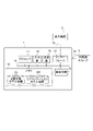
- FIG. 2 shows the hardware configuration of the image processing apparatus 1.
- the image processing device 1 mainly includes a processor 11 , a memory 12 , an interface 13 , an input section 14 , a light source section 15 and a sound output section 16 . Each of these elements is connected via a data bus 19 .
- the processor 11 executes a predetermined process by executing a program or the like stored in the memory 12.
- the processor 11 is a processor such as a CPU (Central Processing Unit), a GPU (Graphics Processing Unit), or a TPU (Tensor Processing Unit).
- Processor 11 may be composed of a plurality of processors.
- Processor 11 is an example of a computer.
- the memory 12 is composed of various volatile memories used as working memory, such as RAM (Random Access Memory) and ROM (Read Only Memory), and non-volatile memory for storing information necessary for processing of the image processing apparatus 1. be done.
- the memory 12 may include an external storage device such as a hard disk connected to or built into the image processing apparatus 1, or may include a storage medium such as a detachable flash memory.
- the memory 12 stores a program for the image processing apparatus 1 to execute each process in this embodiment.
- the memory 12 also stores binary classification model information D1 and segmentation model information D2. Details of these data will be described later. At least one of the binary classification model information D1 and the segmentation model information D2 may be stored in an external device capable of wired or wireless data communication with the image processing apparatus 1 instead of the memory 12 .
- the interface 13 performs an interface operation between the image processing device 1 and an external device.
- interface 13 provides display information “Ib” generated by processor 11 to display device 2 .
- the interface 13 also supplies the endoscope 3 with light or the like generated by the light source unit 15 .
- the interface 13 also supplies the processor 11 with an electrical signal indicating the captured image Ia supplied from the endoscope 3 .
- the interface 13 may be a communication interface such as a network adapter for performing wired or wireless communication with an external device, and may be a hardware interface conforming to USB (Universal Serial Bus), SATA (Serial AT Attachment), or the like. may
- the input unit 14 generates an input signal based on the operation by the inspector.
- the input unit 14 is, for example, a button, touch panel, remote controller, voice input device, or the like.
- the light source unit 15 generates light to be supplied to the distal end portion 38 of the endoscope 3 .
- the light source unit 15 may also incorporate a pump or the like for sending out water or air to be supplied to the endoscope 3 .
- the sound output unit 16 outputs sound under the control of the processor 11 .
- the binary classification model information D1 is information on a binary classification model that outputs information on classification as to whether or not the photographed image Ia has a lesion site.
- the binary classification model information D1 includes, for example, parameters necessary for constructing a binary classification model.
- the binary classification model is any machine learning model or statistical model, and when a captured image Ia is input, information (classification information) regarding whether or not a lesion site exists in the input captured image Ia. It is a model configured to output.
- the binary classification model may output a binary value (e.g., a value of 0 or 1) according to whether a lesion exists or not. A set may be output, or both of these may be output.
- the "certainty that a lesion exists" and the “certainty that a lesion does not exist” correspond to the "certainty regarding the presence or absence of a lesion", which will be described later.
- the “certainty degree of presence of a lesion site” is a value indicating the degree of possibility that a lesion site is present in the photographed image Ia, and increases as the probability increases.
- the "certainty that a lesion site does not exist” is a value indicating the degree of possibility that a lesion site does not exist in the photographed image Ia, and increases as the probability increases.
- a binary classification model is an example of a "classification model.”
- FIG. 3(A) is a schematic diagram of a binary classification model configured based on the binary classification model information D1.
- the binary classification model has a feature extractor and a score calculator.
- the feature extractor extracts a feature quantity of a predetermined number of dimensions when the photographed image Ia is input, and supplies a feature vector representing the extracted feature quantity to the score calculator.
- the score calculator outputs a score (in FIG. 3A, the certainty that a lesion is present and the certainty that a lesion is not present) by inputting the feature vector from the feature extractor.
- the binary classification model may be, for example, a model based on logistic regression, k-nearest neighbor method, boosting, decision tree, neural network, support vector machine, or the like.
- the neural network architecture for example, AlexNet, VGG, ResNet, SqueezeNet, DenseNet, Inception, GoogleNet, ShuffleNet, MobileNet, ResNeXt, Wide ReNet, NASNet, etc. may be adopted.
- the binary classification model information D1 includes, for example, the layer structure, the neuron structure of each layer, the number and size of filters in each layer, and the weight of each element of each filter. contains various parameters of
- the segmentation model information D2 is information about a segmentation model for extracting an area (also referred to as a "lesion image area Tc") within the captured image Ia that constitutes the lesion site from the input image.
- the segmentation model information D2 includes parameters necessary for constructing the segmentation model.
- the segmentation model is, for example, a machine learning model such as a neural network, and is configured to output the extraction result of the lesion image region Tc in the input captured image Ia when the captured image Ia is input. is a model.
- the extraction result of the lesion image region Tc output by the segmentation model may be, for example, a mask image of the lesion image region Tc (a binary image in which pixels corresponding to the lesion image region Tc and other pixels have different values).
- a reliability map which is a map on the image indicating the reliability of the lesion image region Tc.
- FIG. 3(B) is a schematic diagram of a segmentation model configured based on the segmentation model information D2.
- the segmentation model when a captured image Ia selected by the image processing apparatus 1 is input, the segmentation model is a mask image representing a lesion image region Tc in the input captured image Ia. It is output as the extraction result of the image region Tc.
- representative models of neural networks used in segmentation models include, for example, Fully Convolutional Network, SegNet, U-Net, V-Net, Feature Pyramid Network, Mask R-CNN, and DeepLab.
- the image processing device 1 applies a segmentation model to the captured image Ia selected based on the information output by the binary classification model, and displays the extraction result of the lesion image region Tc by the segmentation model on the display device 2. display.
- the image processing apparatus 1 extracts and presents the lesion image region Tc with high accuracy while appropriately reducing the processing load.
- the processing load is lower than that of the segmentation model, and the processing time is shorter than the interval based on the frame rate of the captured image Ia. Therefore, binary classification models are suitable for real-time processing.
- the segmentation model extracts the lesion site (determines the lesion image region Tc)
- the processing load is higher than the binary classification model, and the processing time tends to be longer than the interval based on the frame rate of the captured image Ia. be. This tendency becomes more conspicuous as a highly accurate segmentation model is used.
- the image processing apparatus 1 extracts and presents the lesion image region Tc with high accuracy while maintaining real-time processing.
- FIG. 4 is a functional block diagram of the image processing device 1.
- the processor 11 of the image processing apparatus 1 functionally includes a captured image acquisition unit 30, a classification unit 31, a lesion candidate section detection unit 32, an image selection unit 33, and an area extraction unit. 34 and a display control unit 35 .
- the blocks that exchange data are connected by solid lines, but the combinations of blocks that exchange data are not limited to those shown in FIG. The same applies to other functional block diagrams to be described later.
- the captured image acquisition unit 30 acquires captured images Ia captured by the endoscope 3 via the interface 13 at predetermined intervals. Then, the captured image acquisition unit 30 supplies the acquired captured image Ia to the classification unit 31, the image selection unit 33, and the display control unit 35, respectively.
- the classification unit 31 classifies each photographed image Ia acquired by the photographed image acquisition unit 30 as to whether or not a lesion site is included. supply to In this case, the classification unit 31 configures a binary classification model by referring to the binary classification model information D1, and inputs the captured image Ia acquired by the captured image acquisition unit 30 to the configured binary classification model. Thus, the classification result Rc is obtained.
- the classification unit 31 may include, in the classification result Rc supplied to the image selection unit 33, the feature vector output by the feature extractor of the binary classification model in addition to the certainty of each presence or absence of the lesion site. . This feature vector is used for selection of the captured image Ia by the image selection unit 33, as will be described later.
- the lesion candidate section detection unit 32 Based on the classification result Rc for each captured image Ia supplied from the classification unit 31, the lesion candidate section detection unit 32 detects a continuous section (also referred to as “lesion candidate section St”) of the captured images Ia classified as containing a lesion site. ) is detected. In this case, for example, if the latest captured image Ia is classified as an image having a lesion site (including the case where the lesion site presence confidence is higher than the lesion site absence confidence), the lesion candidate section detection unit 32 detects that there is a lesion candidate section St including the photographed image Ia. On the other hand, when the lesion candidate section detection unit 32 is detecting the lesion candidate section St, if the latest captured image Ia is classified as an image having no lesion site, the lesion candidate section St ends. determined to be Then, the lesion candidate section detection unit 32 supplies the section detection result “Rd” regarding the lesion candidate section St to the image selection unit 33 .
- a continuous section also referred to as “lesion candidate section
- the image selection unit 33 selects an image to which the segmentation model is applied (also referred to as “segmentation target image Itag”) from the photographed image Ia corresponding to the lesion candidate section St. . A method of selecting the segmentation target image Itag will be described later.
- the image selection unit 33 supplies the selected segmentation target image Itag to the region extraction unit 34 .
- the region extraction unit 34 performs processing for extracting the lesion image region Tc from the segmentation target image Itag selected by the image selection unit 33 .
- the region extraction unit 34 inputs the segmentation target image Itag to the segmentation model specified based on the segmentation model information D2, thereby obtaining the extraction result of the lesion image region Tc.
- the region extraction unit 34 supplies the region extraction result “Re” regarding the lesion image region Tc to the display control unit 35 .
- the display control unit 35 generates the display information Ib based on the captured image Ia and the region extraction result Re, and supplies the display information Ib to the display device 2 via the interface 13 to display the captured image Ia and the lesion image. Information about the area Tc is displayed on the display device 2 .
- a display example of the display control unit 35 will be described later.
- each component may be realized by recording necessary programs in an arbitrary nonvolatile storage medium and installing them as necessary.
- at least part of each of these components may be realized by any combination of hardware, firmware, and software, without being limited to being implemented by program software.
- at least part of each of these components may be implemented using a user-programmable integrated circuit, such as an FPGA (Field-Programmable Gate Array) or a microcontroller. In this case, this integrated circuit may be used to implement a program composed of the above components.
- FPGA Field-Programmable Gate Array
- each component may be configured by an ASSP (Application Specific Standard Produce), an ASIC (Application Specific Integrated Circuit), or a quantum processor (quantum computer control chip).
- ASSP Application Specific Standard Produce
- ASIC Application Specific Integrated Circuit
- quantum processor quantum computer control chip
- the image selection unit 33 selects a segmentation target image Itag based on the classification result Rc of each photographed image Ia in order to select an image of a location where the output of the binary classification model is stable in the lesion candidate section St.
- the lesion image region Tc will be extracted with high accuracy by applying the segmentation model. Further, based on the lesion image region Tc extracted with high accuracy in this manner, it is possible to present an image suitable as a display image to be presented to the examiner.
- the image selection unit 33 selects the segmentation target image Itag from the predetermined number of captured images Ia when the condition regarding the classification result Rc of each captured image Ia is satisfied consecutively in time series.
- the condition regarding the classification result Rc may be a condition regarding the degree of certainty regarding the presence or absence of the lesion site in the photographed image Ia, or may be a condition based on the feature vector extracted from the photographed image Ia.
- the image selection unit 33 may select the segmentation target image Itag based on the degree of certainty regarding the presence or absence of the lesion site in the captured image Ia, and select the segmentation target image Itag based on the feature vector extracted from the captured image Ia.
- You may Hereinafter, a method for selecting a segmentation target image Itag based on the degree of certainty regarding the presence or absence of a lesion site in the captured image Ia and a method for selecting a segmentation target image Itag based on a feature vector extracted from the captured image Ia will be described in order.
- the image selection unit 33 determines whether or not to apply the segmentation model based on the confidence regarding the presence or absence of a lesion site output by the binary classification model, and configures the lesion candidate section St.
- the segmentation target image Itag may be selected from the captured image Ia.
- the image selection unit 33 determines that the certainty of the presence of a lesion site is equal to or greater than a predetermined threshold (also referred to as “first threshold t1”) and the difference in the certainty of presence of a lesion site is a predetermined threshold (“second threshold t1”). It is also referred to as “threshold value t2”.), and a predetermined number “N” (N is an integer equal to or greater than 2) of captured images Ia continues, it is determined that the application condition of the segmentation model is satisfied. Then, the image selection unit 33 selects the N-th (that is, the latest) photographed image Ia among the N photographed images Ia that satisfy the application condition of the segmentation model as the segmentation target image Itag.
- the first threshold value t1, the second threshold value t2, and the number of sheets N relating to the application condition of the segmentation model are determined in advance in consideration of the classification accuracy of the binary classification model, etc., and stored in advance in the memory 12 or the like.
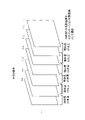
- FIG. 5 is a schematic diagram of a method of selecting a segmentation target image Itag based on certainty.
- the latest captured image Ia acquired at time "T” and the six captured images Ia acquired immediately before the captured image Ia are denoted as acquired times "T" to "T-6". are displayed in association with each other.
- the photographed images Ia for which the certainty of the existence of the lesion site is equal to or greater than the first threshold value t1 are indicated by hatching.
- the number of sheets N is set to "3".
- the image selection unit 33 selects a predetermined number N of consecutive photographed images Ia in which the certainty of the presence of a lesion site is equal to or greater than the first threshold t1 and the difference in the certainty of the presence of a lesion site is less than the second threshold t2. Therefore, the captured image Ia at the time T, which is the Nth captured image Ia, is selected as the segmentation target image Itag. As a result, the image selection unit 33 can suitably select the photographed image Ia of the part where the output of the binary classification model is stable as the segmentation target image Itag.
- the photographed image Ia acquired at time "T-5" also has a certainty that there is a lesion site that is equal to or greater than the first threshold value t1, the certainty that a lesion site exists in successive photographed images Ia. is less than the first threshold value t1, and does not satisfy the application condition of the segmentation model regarding the number of sheets N. Therefore, the captured image Ia acquired at time "T-5" is not selected as the segmentation target image Itag.
- the image selection unit 33 may dynamically change the number N according to the selection of the segmentation target image Itag. For example, after selecting a segmentation target image Itag in a certain lesion candidate section St, the image selection unit 33 sets the number N to be larger by a predetermined number in the lesion candidate section St. Then, when the application condition of the segmentation model after increasing the number N is satisfied, the image selection unit 33 selects the segmentation target image Itag again.
- the image selection unit 33 changes the number N from “3” to "5" after selecting the captured image Ia at time T as the segmentation target image Itag. Then, the image selection unit 33 determines that the certainty that the photographed image Ia acquired at the time “T+1” and the time “T+2” has a lesion site is equal to or higher than the first threshold value t1, and If the difference in confidence that there is a lesion site in the captured image Ia is less than the second threshold value t2, the captured image Ia acquired at time "T+2" is selected as the segmentation target image Itag. After that, the segmentation target image Itag selected by the image selection unit 33 is supplied to the region extraction unit 34 .
- the image selection unit 33 can additionally select the segmentation target image Itag in the lesion candidate section St and suitably update the display of the lesion image region Tc displayed on the display device 2 .
- the image selection unit 33 recognizes that the latest photographed image Ia does not belong to the lesion candidate section St based on the section detection result Rd generated by the lesion candidate section detection unit 32, the image selection unit 33 sets the number of sheets N to the initial value "3 ”.
- the image selection unit 33 may change at least one of the first threshold t1 and the second threshold t2 when increasing the number N of images. For example, when increasing the number N of images, the image selection unit 33 increases the first threshold t1 by a predetermined value or decreases the second threshold t2 by a predetermined value. This makes it possible to make adjustments so that the segmentation target image Itag representing the same lesion site is less likely to be selected (that is, the display of the lesion image region Tc is less likely to be updated). On the other hand, when increasing the number N of images, the image selection unit 33 decreases the first threshold t1 by a predetermined value or increases the second threshold t2 by a predetermined value. As a result, it is possible to make adjustments so that the segmentation target image Itag representing the same lesion site is easily selected (that is, the display of the lesion image region Tc is easily updated).
- the image selection unit 33 sets the number N to a value smaller than the initial value when the lesion candidate section St is detected again immediately after the lesion candidate section St ends.
- the lesion candidate section St ends when the certainty of the existence of the lesion site in the photographed image Ia acquired at time T+1 becomes lower than the certainty of the existence of the lesion site.
- the image selection unit 33 sets the number N to a predetermined value smaller than the initial value.
- the image selection unit 33 may select the segmentation target image Itag from the captured images Ia other than the Nth captured image Ia when the conditions for applying the segmentation model are satisfied. For example, the image selection unit 33 may select, as the segmentation target image Itag, the captured image Ia with the highest degree of certainty that there is a lesion site among the N captured images Ia that satisfy the segmentation model application conditions.
- the image selection unit 33 determines whether or not to apply the segmentation model based on the feature vector output by the feature extractor of the binary classification model, and configures the lesion candidate section St.
- the segmentation target image Itag may be selected from the captured image Ia.
- the image selection unit 33 calculates the degree of similarity (for example, cosine similarity) between two consecutive photographed images Ia based on the inner product of the feature vectors of these photographed images Ia. Then, the image selection unit 33 calculates the degree of similarity for each of the N consecutive captured images Ia. , it is determined that the application condition of the segmentation model is satisfied. In this case, the image selection unit 33 selects the N-th (that is, the latest) captured image Ia as the segmentation target image Itag.
- the degree of similarity for example, cosine similarity
- FIG. 6 is a schematic diagram of a method of selecting a segmentation target image Itag based on feature vectors.
- the latest captured image Ia acquired at time T and the six captured images Ia acquired from time T-1 to time T-6 immediately before the captured image Ia are It is displayed in association with the acquired time.
- the number of sheets N is set to "3".
- the degree of similarity based on the inner product of the feature vectors is calculated for each of the two consecutive captured images Ia. Then, the image selection unit 33 compares the calculated degree of similarity with a third threshold value t3, and determines whether or not the degree of similarity equal to or higher than the third threshold value t3 is satisfied in consecutive N images (three images in this case). Then, the image selection unit 33 determines which of the similarities between the photographed images Ia acquired at the times T ⁇ 2 and T ⁇ 1 and the similarities between the photographed images Ia acquired at the times T ⁇ 1 and T is is equal to or greater than the third threshold value t3, it is determined that the conditions for applying the segmentation model are satisfied for the consecutive N shot images Ia from time T-2 to time T. Therefore, in this case, the image selection unit 33 selects the captured image Ia acquired at time T as the segmentation target image Itag.
- the image selection unit 33 can suitably select the photographed image Ia of the part where the output of the binary classification model is stable as the segmentation target image Itag. It should be noted that the image selection unit 33 may dynamically change the number of images N, similarly to the method of selecting the segmentation target image Itag based on the degree of certainty. Further, when the image selection unit 33 increases the number N according to the selection of the segmentation target image Itag, the update frequency of the lesion image region Tc is adjusted by similarly changing the third threshold value t3. good. Further, instead of selecting the Nth captured image Ia as the segmentation target image Itag, the image selection unit 33 selects the segmentation target image Itag from the N captured images Ia other than the captured image Ia based on the certainty. You may choose.
- the image selection unit 33 may combine the method of selecting the segmentation target image Itag based on the degree of certainty and the method of selecting the segmentation target image Itag based on the feature vector. In this case, the image selection unit 33 selects the segmentation target image Itag when both the conditions for applying the segmentation model based on certainty and the conditions for applying the segmentation model based on feature vectors are satisfied.
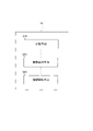
- FIG. 7 shows a display example of a display screen displayed by the display device 2 during an endoscopy.
- the display control unit 35 of the image processing device 1 transmits display information Ib generated based on the captured image Ia acquired by the captured image acquisition unit 30 and the region extraction result Re generated by the region extraction unit 34 to the display device 2. Then, the display screen shown in FIG. 7 is displayed on the display device 2 .
- the display control unit 35 of the image processing apparatus 1 displays the latest image display area 70 representing the latest captured image Ia acquired by the captured image acquisition unit 30 and the lesion image area Tc based on the area extraction result Re.
- a lesion site display area 71 for displaying a clearly defined mask image is provided on the display screen.
- the lesion candidate section detection unit 32 detects that it is a lesion candidate section St, and the image selection unit 33 determines the application condition of the segmentation model based on the certainty or the feature vector, and determines the segmentation target image Itag. make a choice.
- the area extraction unit 34 applies the segmentation model to the selected segmentation target image Itag to extract the lesion image area Tc, and the display control unit 35 extracts the lesion image area Tc extracted by the area extraction unit 34.
- a mask image representing the lesion is displayed in the lesion site display area 71 .
- the display control unit 35 also displays a moving image based on the latest captured image Ia acquired by the captured image acquisition unit 30 on the latest image display area 70 .
- the display control unit 35 presents the corresponding lesion image region Tc together with the latest captured image Ia, thereby suitably assisting the examiner in grasping the lesion site.
- the display control unit 35 provides the latest image display area 70 and the lesion site display area 71 instead of providing the latest image display area 70 and the lesion site display area 71, respectively.
- the detected lesion image region Tc may be highlighted on the latest captured image Ia.
- the display control unit 35 emphasizes the lesion image region Tc by applying a fringing effect to the edges of the lesion image region Tc on the captured image Ia to be displayed based on the mask image representing the lesion image region Tc.
- the entire portion corresponding to the lesion image region Tc may be set to a predetermined pixel value and highlighted.
- the display control unit 35 displays a reliability map representing the reliability of whether each pixel corresponds to the lesion image region Tc. may be displayed.
- the image selection unit 33 After the image representing the lesion image region Tc is displayed in the lesion site display region 71, when the lesion candidate section St continues, the image selection unit 33 newly selects the segmentation target image Itag, and the region extraction unit 34 extracts the region.
- the display control unit 35 updates the display of the lesion site display area 71 with an image representing the lesion image area Tc based on the newly generated area extraction result Re. Thereby, the display control unit 35 can appropriately update the display of the lesion site display area 71 based on the latest segmentation target image Itag selected by the image selection unit 33 .
- the display control unit 35 displays the lesion site based on the area of the lesion image region Tc. It may be determined whether or not the display of the area 71 needs to be updated. Specifically, the display control unit 35 determines that the newly generated area extraction result Re When the area of the lesion image region Tc represented by is large, the display of the lesion site display region 71 is updated based on the newly generated region extraction result Re.
- the display control unit 35 selects the lesion image region Tc to be displayed based on the area of the corresponding lesion image region Tc.
- a segmentation target image Itag is determined. By doing so, the display control unit 35 can display an image that suitably represents the lesion site in the lesion site display area 71 .
- the display control unit 35 preferably stops displaying the image in the lesion site display area 71 when the latest captured image Ia no longer belongs to the lesion candidate section St. In this case, the display control unit 35 displays the image being displayed in the lesion site display area 71 based on the section detection result Rd generated by the lesion candidate section detection unit 32 when detecting that the lesion candidate section St ends. You want to hide. As a result, the display control unit 35 preferably suppresses continued display of an image clearly indicating a lesion site that is no longer an object to be imaged by the endoscope 3 .
- the display control unit 35 does not update the display of the image in the lesion site display area 71 (that is, update stop). In this case, the display control unit 35 continues (fixes) the display of the image displayed in the lesion site display area 71 at the time of detecting a predetermined input based on the operation of the input unit 14 by the examiner. Then, the display control unit 35 resumes updating the display of the image in the lesion site display area 71 when a predetermined input permitting updating of the display of the image in the lesion site display area 71 is detected.
- the display control unit 35 stops the update of the display of the lesion image region Tc in accordance with the external input based on the operation of the input unit 14 by the examiner, so that the display of the lesion image region Tc is sufficiently displayed to the examiner. You can give them enough time to check.
- FIG. 8 is an example of a flow chart showing an outline of processing executed by the image processing apparatus 1 during endoscopy in the first embodiment.
- the captured image acquisition unit 30 of the image processing device 1 acquires the captured image Ia (step S11).
- the captured image acquisition unit 30 of the image processing apparatus 1 receives the captured image Ia from the endoscope 3 via the interface 13 .
- the classification unit 31 of the image processing device 1 classifies the captured image Ia acquired in step S11 using the binary classification model configured based on the binary classification model information D1 (step S12).
- the candidate lesion section detection unit 32 of the image processing apparatus 1 determines whether or not it corresponds to the candidate lesion section St (step S13). Then, if it corresponds to the lesion candidate section St (step S13; Yes), the process proceeds to step S14.
- the display control unit 35 causes the display device 2 to display the captured image Ia acquired in step S11 (step S18). Note that the display control unit 35 preferably erases the display of the lesion image region Tc when displaying the lesion image region Tc based on step S17, which will be described later.
- the image selection unit 33 of the image processing device 1 determines whether or not the conditions for applying the segmentation model are satisfied (step S14). In this case, for example, the image selection unit 33 determines whether or not the application condition of the segmentation model based on at least one of the confidence factor and the feature vector described in the section “(5) Selection of segmentation target image ” is satisfied. Then, when it is determined that the application condition of the segmentation model is satisfied (step S14; Yes), the image selection unit 33 selects the segmentation target image Itag (step S15).
- the image selection unit 33 may select the latest captured image Ia as the segmentation target image Itag, or may select the segmentation target image Itag based on the degree of certainty that there is a lesion site. Then, the area extracting unit 34 extracts the lesion image area Tc by applying the segmentation model configured based on the segmentation model information D2 to the segmentation target image Itag (step S16). Then, the display control unit 35 causes the display device 2 to display the latest captured image Ia and the lesion image region Tc extracted in step S16 (step S17).
- step S19 the image processing apparatus 1 determines whether the endoscopy has ended. For example, the image processing apparatus 1 determines that the endoscopy has ended when a predetermined input or the like to the input unit 14 or the operation unit 36 is detected. When the image processing apparatus 1 determines that the endoscopy has ended (step S19; Yes), the processing of the flowchart ends. On the other hand, when the image processing apparatus 1 determines that the endoscopy has not ended (step S19; No), the process returns to step S11. Then, the image processing apparatus 1 executes the processing of steps S11 to S19 on the photographed image Ia newly generated by the endoscope 3. FIG.
- the image processing apparatus 1 may process, after the examination, a video composed of the photographed image Ia generated during the endoscopy.
- the image processing apparatus 1 when an image to be processed is specified based on a user's input from the input unit 14 or the like at an arbitrary timing after the examination, the image processing apparatus 1 performs time-series photographed images constituting the image.
- the processing of the flowchart of FIG. 8 is sequentially performed for Ia. If the image processing apparatus 1 determines that the target video has ended in step S19, it ends the processing of the flowchart.
- the process of the flowchart is performed on the photographed image Ia of .
- Modification 2 The binary classification model information D1 and the segmentation model information D2 may be stored in a storage device separate from the image processing device 1. FIG.
- FIG. 9 is a schematic configuration diagram of an endoscopy system 100A in modified example 2.
- FIG. 9 Note that the display device 2, the endoscope 3, and the like are not shown in FIG. 9 for the sake of simplification.
- An endoscopy system 100A shown in FIG. 9 includes a server device 4 that stores binary classification model information D1 and segmentation model information D2.
- the endoscopy system 100A also includes a plurality of image processing apparatuses 1 (1A, 1B, . . . ) capable of data communication with the server apparatus 4 via a network.
- each image processing device 1 refers to the binary classification model information D1 and the segmentation model information D2 via the network.
- the interface 13 of each image processing apparatus 1 includes a communication interface such as a network adapter for communication.
- each image processing device 1 can refer to the binary classification model information D1 and the segmentation model information D2 and suitably execute the extraction processing and the display processing of the lesion image region Tc, as in the above-described embodiment. can.
- a target to be detected by the detection model is not limited to a lesion site, and may be any attention point that an examiner needs to pay attention to. Such points of interest are not limited to lesion sites, but include areas with inflammation, surgical scars and other cuts, folds and projections, and the tip 38 of the endoscope 3. It may also be a location on the wall surface in the lumen that is easily contacted (easily broken).
- the image processing apparatus 1 may use a classification model that performs three or more types of classification instead of the binary classification model.
- the classification model used by the image processing apparatus 1 may be a model that classifies X+1 types of "lesion type 1" to "lesion type X" (where "X" is an integer equal to or greater than 2) and "non-lesion”.
- the memory 12 instead of the binary classification model information D1, stores classification model information, which is information about a classification model that performs three or more types of classification. By referring to , a classification result for the captured image Ia is generated.
- the classification model used by the image processing apparatus is not limited to a binary classification model as long as it is a model that determines "presence or absence of a lesion" as a function.
- FIG. 10 is a block diagram of an image processing device 1X according to the second embodiment.
- the image processing device 1X includes a classifying means 31X, an image selecting means 33X, and an area extracting means 34X.
- the classification means 31X classifies each time-series photographed image obtained by photographing the inspection object by the photographing unit provided in the endoscope as to whether or not it includes a region of interest to be noticed.
- the classifying means 31X can be the classifying section 31 in the first embodiment (including modifications; the same applies hereinafter). Note that the classification unit 31X may immediately acquire the captured image generated by the imaging unit, or may acquire, at a predetermined timing, the captured image generated by the imaging unit and stored in the storage device in advance.
- the image selection means 33X selects a target image from which the region of interest is to be extracted from the captured image based on the result of classification.
- the image selection means 33X can be the image selection section 33 in the first embodiment.
- the region extracting means 34X extracts the target region region from the target image.
- the region extracting means 34X can be the region extracting section 34 in the first embodiment.
- FIG. 11 is an example of a flowchart showing a processing procedure in the second embodiment.
- the classification means 31X classifies each time-series photographed image obtained by photographing an object to be inspected by the photographing unit provided in the endoscope as to whether or not it includes a region of interest to be noticed (step S21).
- the image selection means 33X selects a target image from which the region of interest is to be extracted from the captured images based on the result of the classification (step S22).
- the area extracting means 34X extracts the area of the site of interest from the target image (step S23).
- the image processing apparatus 1X limits the target image from which the region of interest is extracted based on the classification result of whether or not the region of interest is included, and reduces the processing load.
- the region of the site of interest can be preferably extracted.
- [Appendix 1] a classifying means for classifying each time-series photographed image obtained by photographing an inspection target by an imaging unit provided in an endoscope as to whether or not it includes a region of interest to be noticed; image selection means for selecting, from the captured images, a target image from which the region of interest is to be extracted, based on the result of the classification; an area extracting means for extracting an area of the target part from the target image;
- the method according to appendix 1 or 2 wherein when an image is input, the classification means performs the classification for each of the time-series captured images based on a classification model that outputs information regarding the presence or absence of a region of interest in the image. image processing device.
- the classification model outputs a confidence level regarding the presence or absence of the target site, 3.
- Appendix 5 5.
- the classification means performs feature extraction on the input image, 6.
- the image processing apparatus according to any one of attachments 1 to 5, wherein the image selection means selects the target image based on a feature vector obtained by the feature extraction.
- the image selection means selects the target image from the predetermined number of photographed images when a condition regarding the degree of similarity of the photographed images calculated based on the feature vector is satisfied for a predetermined number of consecutive photographed images in the time series.
- the image processing device according to appendix 6.
- Appendix 8 8.
- the image selection means according to any one of Supplementary Notes 2, 5, and 7, wherein the predetermined number is changed after the target image is selected in a section in which the photographed images classified as including the target region are continuous.
- the image processing device according to .
- the region extracting means extracts the region of the region of interest from the target image based on a segmentation model, which is a model that outputs information about the region of the region of interest in the image when an image is input.
- a segmentation model which is a model that outputs information about the region of the region of interest in the image when an image is input.
- the image processing device according to any one of 8.
- the image processing apparatus according to any one of attachments 1 to 9, further comprising display control means for causing a display device to display information about the region of interest.
- the display control means determines the target site based on the area of the target site. 11.
- the image processing apparatus according to appendix 10, wherein the target image for which information about the area of is to be displayed is determined.
- Appendix 12 12. The image processing apparatus according to appendix 10 or 11, wherein the display control means stops updating the display of the information regarding the region of interest based on an external input.
- Appendix 13 the computer Classifying each time-series photographed image of an inspection object photographed by an imaging unit provided in an endoscope as to whether or not it includes a region of interest to be noticed, selecting a target image from which the region of interest is to be extracted from the captured image based on the result of the classification; extracting the region of the target part from the target image; Image processing method.
- Appendix 14 Classifying each time-series photographed image of an inspection object photographed by an imaging unit provided in an endoscope as to whether or not it includes a region of interest to be noticed, selecting a target image from which the region of interest is to be extracted from the captured image based on the result of the classification;
- a storage medium storing a program for causing a computer to execute processing for extracting the region of interest from the target image.
Abstract
Description
内視鏡に設けられた撮影部により検査対象を撮影した時系列の撮影画像の各々に対し、注目すべき注目部位を含んでいるか否かの分類を行う分類手段と、
前記分類の結果に基づき、前記注目部位の領域を抽出する対象となる対象画像を前記撮影画像から選択する画像選択手段と、
前記対象画像から前記注目部位の領域を抽出する領域抽出手段と、
を有する画像処理装置である。 In one aspect of the image processing device,
a classifying means for classifying each time-series photographed image obtained by photographing an inspection target by an imaging unit provided in an endoscope as to whether or not it includes a region of interest to be noticed;
image selection means for selecting, from the captured images, a target image from which the region of interest is to be extracted, based on the result of the classification;
an area extracting means for extracting an area of the target part from the target image;
It is an image processing apparatus having
コンピュータが、
内視鏡に設けられた撮影部により検査対象を撮影した時系列の撮影画像の各々に対し、注目すべき注目部位を含んでいるか否かを分類し、
前記分類の結果に基づき、前記注目部位の領域を抽出する対象となる対象画像を前記撮影画像から選択し、
前記対象画像から前記注目部位の領域を抽出する、
画像処理方法である。 In one aspect of the image processing method,
the computer
Classifying each time-series photographed image of an inspection object photographed by an imaging unit provided in an endoscope as to whether or not it includes a region of interest to be noticed,
selecting a target image from which the region of interest is to be extracted from the captured image based on the result of the classification;
extracting the region of the target part from the target image;
It is an image processing method.
内視鏡に設けられた撮影部により検査対象を撮影した時系列の撮影画像の各々に対し、注目すべき注目部位を含んでいるか否かを分類し、
前記分類の結果に基づき、前記注目部位の領域を抽出する対象となる対象画像を前記撮影画像から選択し、
前記対象画像から前記注目部位の領域を抽出する処理をコンピュータに実行させるプログラムを格納した記憶媒体である。 One aspect of the storage medium is
Classifying each time-series photographed image of an inspection object photographed by an imaging unit provided in an endoscope as to whether or not it includes a region of interest to be noticed,
selecting a target image from which the region of interest is to be extracted from the captured image based on the result of the classification;
A storage medium storing a program for causing a computer to execute processing for extracting the region of interest from the target image.
(1)システム構成
図1は、内視鏡検査システム100の概略構成を示す。図1に示すように、内視鏡検査システム100は、内視鏡を利用した検査又は治療を行う医師等の検査者に対して病変の疑いがある部位(病変部位)を提示するシステムであって、主に、画像処理装置1と、表示装置2と、画像処理装置1に接続された内視鏡スコープ3と、を備える。 <First Embodiment>
(1) System Configuration FIG. 1 shows a schematic configuration of an endoscopy system 100. As shown in FIG. As shown in FIG. 1, an endoscopy system 100 is a system that presents a site suspected of having a lesion (lesion site) to an examiner such as a doctor who performs an examination or treatment using an endoscope. It mainly includes an
(a)頭頚部:咽頭ガン、悪性リンパ腫、乳頭腫
(b)食道:食道ガン、食道炎、食道裂孔ヘルニア、バレット食道、食道静脈瘤、食道アカラシア、食道粘膜下腫瘍、食道良性腫瘍
(c)胃:胃ガン、胃炎、胃潰瘍、胃ポリープ、胃腫瘍
(d)十二指腸:十二指腸ガン、十二指腸潰瘍、十二指腸炎、十二指腸腫瘍、十二指腸リンパ腫
(e)小腸:小腸ガン、小腸腫瘍性疾患、小腸炎症性疾患、小腸血管性疾患
(f)大腸:大腸ガン、大腸腫瘍性疾患、大腸炎症性疾患、大腸ポリープ、大腸ポリポーシス、クローン病、大腸炎、腸結核、痔 As a representative example, processing in colonoscopy will be described below, but the inspection target is not limited to the large intestine, and may be the esophagus or the stomach. In addition, endoscopes targeted in the present disclosure include, for example, pharyngeal endoscopes, bronchoscopes, upper gastrointestinal endoscopes, duodenal endoscopes, small intestine endoscopes, colonoscopes, capsule endoscopes, thoracic scopes, laparoscopes, cystoscopes, choledoscopes, arthroscopes, spinal endoscopes, angioscopes, epidural endoscopes, and the like. Further, the disease conditions of the lesion site to be detected in the present disclosure are exemplified as (a) to (f) below.
(a) Head and neck: pharyngeal cancer, malignant lymphoma, papilloma (b) Esophagus: esophageal cancer, esophagitis, hiatal hernia, Barrett's esophagus, esophageal varices, esophageal achalasia, esophageal submucosal tumor, esophageal benign tumor (c) Stomach: gastric cancer, gastritis, gastric ulcer, gastric polyp, gastric tumor (d) Duodenum: duodenal cancer, duodenal ulcer, duodenitis, duodenal tumor, duodenal lymphoma (e) Small intestine: small bowel cancer, small bowel neoplastic disease, small bowel inflammatory disease , small intestinal vascular disease (f) colon: colon cancer, colon neoplastic disease, colon inflammatory disease, colon polyp, colon polyposis, Crohn's disease, colitis, intestinal tuberculosis, hemorrhoids
図2は、画像処理装置1のハードウェア構成を示す。画像処理装置1は、主に、プロセッサ11と、メモリ12と、インターフェース13と、入力部14と、光源部15と、音出力部16と、を含む。これらの各要素は、データバス19を介して接続されている。 (2) Hardware Configuration FIG. 2 shows the hardware configuration of the
次に、2値分類モデル情報D1及びセグメンテーションモデル情報D2について説明する。 (3) Outline of Data Next, the binary classification model information D1 and the segmentation model information D2 will be explained.
次に、画像処理装置1が実行する病変画像領域Tcの抽出及び表示に関する処理について説明する。概略的には、画像処理装置1は、2値分類モデルが出力する情報に基づき選択した撮影画像Iaに対してセグメンテーションモデルを適用し、セグメンテーションモデルによる病変画像領域Tcの抽出結果を表示装置2に表示させる。これにより、画像処理装置1は、処理負荷を好適に低減しつつ、高精度な病変画像領域Tcの抽出及び提示を行う。 (4) Extraction and Display of Lesion Image Area Next, the processing relating to the extraction and display of the lesion image area Tc executed by the
次に、病変候補区間検出部32が病変候補区間Stを検出した場合に画像選択部33が実行するセグメンテーション対象画像Itagの選択方法について具体的に説明する。画像選択部33は、病変候補区間Stにおいて2値分類モデルの出力が安定している箇所の画像を選択するため、各撮影画像Iaの分類結果Rcに基づきセグメンテーション対象画像Itagを選択する。このように2値分類モデルの出力が安定している箇所の画像をセグメンテーション対象画像Itagとして選択することにより、例えば検査者による内視鏡操作に起因する画像のボケ・ブレが小さいセグメンテーション対象画像Itagの選択が可能となる。この画像選択に伴い、セグメンテーションモデル適用による高精度な病変画像領域Tcの抽出が期待される。また、このように高精度に抽出された病変画像領域Tcに基づいて、検査者に提示する表示画像として好適な画像を提示することが可能となる。 (5) Selection of Segmentation Target Image Next, a method of selecting a segmentation target image Itag executed by the image selection section 33 when the lesion candidate
画像選択部33は、2値分類モデルが出力する病変部位の有無に関する確信度に基づき、セグメンテーションモデルの適用要否を判定し、病変候補区間Stを構成する撮影画像Iaからセグメンテーション対象画像Itagを選択してもよい。 (5-1) Selection Method Based on Confidence The image selection unit 33 determines whether or not to apply the segmentation model based on the confidence regarding the presence or absence of a lesion site output by the binary classification model, and configures the lesion candidate section St. The segmentation target image Itag may be selected from the captured image Ia.
画像選択部33は、2値分類モデルの特徴抽出器が出力する特徴ベクトルに基づき、セグメンテーションモデルの適用要否を判定し、病変候補区間Stを構成する撮影画像Iaからセグメンテーション対象画像Itagを選択してもよい。 (5-2) Selection Method Based on Feature Vector The image selection unit 33 determines whether or not to apply the segmentation model based on the feature vector output by the feature extractor of the binary classification model, and configures the lesion candidate section St. The segmentation target image Itag may be selected from the captured image Ia.
次に、表示制御部35が実行する表示装置2の表示制御について説明する。 (6) Display Control Next, the display control of the
図8は、第1実施形態において内視鏡検査時に画像処理装置1が実行する処理の概要を示すフローチャートの一例である。 (7) Processing Flow FIG. 8 is an example of a flow chart showing an outline of processing executed by the
次に、上述した実施形態に好適な変形例について説明する。以下の変形例は、組み合わせて上述の実施形態に適用してもよい。 (8) Modification Next, a modification suitable for the above-described embodiment will be described. The following modifications may be combined and applied to the above-described embodiment.
画像処理装置1は、内視鏡検査時に生成された撮影画像Iaから構成された映像を、検査後において処理してもよい。 (Modification 1)
The
2値分類モデル情報D1及びセグメンテーションモデル情報D2は、画像処理装置1とは別の記憶装置に記憶されてもよい。 (Modification 2)
The binary classification model information D1 and the segmentation model information D2 may be stored in a storage device separate from the
検知モデルにより検知する対象は、病変部位に限らず、検査者が注目する必要がある任意の注目箇所であってもよい。このような注目箇所は、病変部位に限らず、炎症が生じている箇所、手術痕その他の切り傷が生じている箇所、ひだや突起が生じている箇所、内視鏡スコープ3の先端部38が管腔内の壁面において接触しやすい(閊えやすい)箇所などであってもよい。 (Modification 3)
A target to be detected by the detection model is not limited to a lesion site, and may be any attention point that an examiner needs to pay attention to. Such points of interest are not limited to lesion sites, but include areas with inflammation, surgical scars and other cuts, folds and projections, and the
画像処理装置1は、2値分類モデルに代えて、3種類以上の分類を行う分類モデルを用いてもよい。例えば、画像処理装置1が用いる分類モデルは、「病変タイプ1」~「病変タイプX」(「X」は2以上の整数)及び「非病変」のX+1種類を分類するモデルであってもよい。この場合、メモリ12には、2値分類モデル情報D1に代えて、3種類以上の分類を行う分類モデルに関する情報である分類モデル情報が記憶されており、画像処理装置1は、当該分類モデル情報を参照することで、撮影画像Iaに対する分類結果を生成する。 (Modification 4)
The
図10は、第2実施形態における画像処理装置1Xのブロック図である。画像処理装置1Xは、分類手段31Xと、画像選択手段33Xと、領域抽出手段34Xとを備える。 <Second embodiment>
FIG. 10 is a block diagram of an image processing device 1X according to the second embodiment. The image processing device 1X includes a classifying means 31X, an image selecting means 33X, and an area extracting means 34X.
内視鏡に設けられた撮影部により検査対象を撮影した時系列の撮影画像の各々に対し、注目すべき注目部位を含んでいるか否かの分類を行う分類手段と、
前記分類の結果に基づき、前記注目部位の領域を抽出する対象となる対象画像を前記撮影画像から選択する画像選択手段と、
前記対象画像から前記注目部位の領域を抽出する領域抽出手段と、
を有する画像処理装置。
[付記2]
前記画像選択手段は、前記分類の結果に関する条件が前記時系列において所定枚数連続して満たされる場合、前記所定枚数の撮影画像から前記対象画像を選択する、付記1に記載の画像処理装置。
[付記3]
前記分類手段は、画像が入力された場合に当該画像内の注目部位の有無に関する情報を出力する分類モデルに基づき、前記時系列の撮影画像の各々に対する前記分類を行う、付記1または2に記載の画像処理装置。
[付記4]
前記分類モデルは、前記注目部位の有無に関する確信度を出力し、
前記画像選択手段は、前記確信度に基づき、前記対象画像を選択する、付記3に記載の画像処理装置。
[付記5]
前記画像選択手段は、前記確信度に関する条件が前記時系列において所定枚数連続して満たされる場合、前記所定枚数の撮影画像から前記対象画像を選択する、付記4に記載の画像処理装置。
[付記6]
前記分類手段は、入力された画像に対する特徴抽出を行い、
前記画像選択手段は、前記特徴抽出により得られる特徴ベクトルに基づき、前記対象画像を選択する、付記1~5のいずれか一項に記載の画像処理装置。
[付記7]
前記画像選択手段は、前記特徴ベクトルに基づき算出した前記撮影画像の類似度に関する条件が、前記時系列において連続する所定枚数において満たされる場合、前記所定枚数の撮影画像から前記対象画像を選択する、付記6に記載の画像処理装置。
[付記8]
前記画像選択手段は、前記注目部位を含んでいると分類される前記撮影画像が連続する区間において、前記対象画像の選択後に前記所定枚数を変更する、付記2、5、7のいずれか一項に記載の画像処理装置。
[付記9]
前記領域抽出手段は、画像が入力された場合に当該画像内の注目部位の領域に関する情報を出力するモデルであるセグメンテーションモデルに基づき、前記対象画像から前記注目部位の領域を抽出する、付記1~8のいずれか一項に記載の画像処理装置。
[付記10]
前記注目部位の領域に関する情報を、表示装置に表示させる表示制御手段をさらに有する、付記1~9のいずれか一項に記載の画像処理装置。
[付記11]
前記注目部位を含んでいると分類される前記撮影画像が連続する区間において、複数の前記対象画像が選択された場合、前記表示制御手段は、前記注目部位の領域の面積に基づき、前記注目部位の領域に関する情報を表示する対象となる前記対象画像を決定する、付記10に記載の画像処理装置。
[付記12]
前記表示制御手段は、外部入力に基づき、前記注目部位の領域に関する情報の表示の更新を停止する、付記10または11に記載の画像処理装置。
[付記13]
コンピュータが、
内視鏡に設けられた撮影部により検査対象を撮影した時系列の撮影画像の各々に対し、注目すべき注目部位を含んでいるか否かを分類し、
前記分類の結果に基づき、前記注目部位の領域を抽出する対象となる対象画像を前記撮影画像から選択し、
前記対象画像から前記注目部位の領域を抽出する、
画像処理方法。
[付記14]
内視鏡に設けられた撮影部により検査対象を撮影した時系列の撮影画像の各々に対し、注目すべき注目部位を含んでいるか否かを分類し、
前記分類の結果に基づき、前記注目部位の領域を抽出する対象となる対象画像を前記撮影画像から選択し、
前記対象画像から前記注目部位の領域を抽出する処理をコンピュータに実行させるプログラムを格納した記憶媒体。 [Appendix 1]
a classifying means for classifying each time-series photographed image obtained by photographing an inspection target by an imaging unit provided in an endoscope as to whether or not it includes a region of interest to be noticed;
image selection means for selecting, from the captured images, a target image from which the region of interest is to be extracted, based on the result of the classification;
an area extracting means for extracting an area of the target part from the target image;
An image processing device having
[Appendix 2]
1. The image processing apparatus according to
[Appendix 3]
3. The method according to
[Appendix 4]
The classification model outputs a confidence level regarding the presence or absence of the target site,
3. The image processing apparatus according to
[Appendix 5]
5. The image processing apparatus according to
[Appendix 6]
The classification means performs feature extraction on the input image,
6. The image processing apparatus according to any one of
[Appendix 7]
The image selection means selects the target image from the predetermined number of photographed images when a condition regarding the degree of similarity of the photographed images calculated based on the feature vector is satisfied for a predetermined number of consecutive photographed images in the time series. The image processing device according to
[Appendix 8]
8. The image selection means according to any one of
[Appendix 9]
The region extracting means extracts the region of the region of interest from the target image based on a segmentation model, which is a model that outputs information about the region of the region of interest in the image when an image is input. 9. The image processing device according to any one of 8.
[Appendix 10]
10. The image processing apparatus according to any one of
[Appendix 11]
When a plurality of target images are selected in a section in which the photographed images classified as containing the target site are continuous, the display control means determines the target site based on the area of the target site. 11. The image processing apparatus according to appendix 10, wherein the target image for which information about the area of is to be displayed is determined.
[Appendix 12]
12. The image processing apparatus according to
[Appendix 13]
the computer
Classifying each time-series photographed image of an inspection object photographed by an imaging unit provided in an endoscope as to whether or not it includes a region of interest to be noticed,
selecting a target image from which the region of interest is to be extracted from the captured image based on the result of the classification;
extracting the region of the target part from the target image;
Image processing method.
[Appendix 14]
Classifying each time-series photographed image of an inspection object photographed by an imaging unit provided in an endoscope as to whether or not it includes a region of interest to be noticed,
selecting a target image from which the region of interest is to be extracted from the captured image based on the result of the classification;
A storage medium storing a program for causing a computer to execute processing for extracting the region of interest from the target image.
2 表示装置
3 内視鏡スコープ
4 サーバ装置
11 プロセッサ
12 メモリ
13 インターフェース
14 入力部
15 光源部
16 音出力部
100、100A 内視鏡検査システム 1, 1X
Claims (14)
- 内視鏡に設けられた撮影部により検査対象を撮影した時系列の撮影画像の各々に対し、注目すべき注目部位を含んでいるか否かを分類する分類手段と、
前記分類の結果に基づき、前記注目部位の領域を抽出する対象となる対象画像を前記撮影画像から選択する画像選択手段と、
前記対象画像から前記注目部位の領域を抽出する領域抽出手段と、
を有する画像処理装置。 Classifying means for classifying whether or not each of time-series photographed images of an inspection target photographed by an imaging unit provided in an endoscope includes a region of interest to be noticed;
image selection means for selecting, from the captured images, a target image from which the region of interest is to be extracted, based on the result of the classification;
an area extracting means for extracting an area of the target part from the target image;
An image processing device having - 前記画像選択手段は、前記分類の結果に関する条件が前記時系列において所定枚数連続して満たされる場合、前記所定枚数の撮影画像から前記対象画像を選択する、請求項1に記載の画像処理装置。 The image processing apparatus according to claim 1, wherein the image selection means selects the target image from the predetermined number of captured images when the condition regarding the result of the classification is satisfied consecutively in the time series.
- 前記分類手段は、画像が入力された場合に当該画像内の注目部位の有無に関する情報を出力する分類モデルに基づき、前記時系列の撮影画像の各々に対する前記分類を行う、請求項1または2に記載の画像処理装置。 3. The method according to claim 1, wherein said classification means classifies each of said time-series photographed images based on a classification model that outputs information regarding the presence or absence of a region of interest in said image when an image is input. The described image processing device.
- 前記分類モデルは、前記注目部位の有無に関する確信度を出力し、
前記画像選択手段は、前記確信度に基づき、前記対象画像を選択する、請求項3に記載の画像処理装置。 The classification model outputs a confidence level regarding the presence or absence of the target site,
4. The image processing apparatus according to claim 3, wherein said image selection means selects said target image based on said certainty. - 前記画像選択手段は、前記確信度に関する条件が前記時系列において所定枚数連続して満たされる場合、前記所定枚数の撮影画像から前記対象画像を選択する、請求項4に記載の画像処理装置。 5. The image processing apparatus according to claim 4, wherein said image selection means selects said target image from said predetermined number of photographed images when said confidence factor condition is satisfied consecutively for a predetermined number in said time series.
- 前記分類手段は、入力された画像に対する特徴抽出を行い、
前記画像選択手段は、前記特徴抽出により得られる特徴ベクトルに基づき、前記対象画像を選択する、請求項1~5のいずれか一項に記載の画像処理装置。 The classification means performs feature extraction on the input image,
6. The image processing apparatus according to claim 1, wherein said image selection means selects said target image based on a feature vector obtained by said feature extraction. - 前記画像選択手段は、前記特徴ベクトルに基づき算出した前記撮影画像の類似度に関する条件が、前記時系列において連続する所定枚数において満たされる場合、前記所定枚数の撮影画像から前記対象画像を選択する、請求項6に記載の画像処理装置。 The image selection means selects the target image from the predetermined number of photographed images when a condition regarding the degree of similarity of the photographed images calculated based on the feature vector is satisfied for a predetermined number of consecutive photographed images in the time series. The image processing apparatus according to claim 6.
- 前記画像選択手段は、前記注目部位を含んでいると分類される前記撮影画像が連続する区間において、前記対象画像の選択後に前記所定枚数を変更する、請求項2、5、7のいずれか一項に記載の画像処理装置。 8. The image selection means according to any one of claims 2, 5, and 7, wherein the predetermined number is changed after the target image is selected in a section in which the photographed images classified as including the target region are continuous. 10. The image processing device according to claim 1.
- 前記領域抽出手段は、画像が入力された場合に当該画像内の注目部位の領域に関する情報を出力するモデルであるセグメンテーションモデルに基づき、前記対象画像から前記注目部位の領域を抽出する、請求項1~8のいずれか一項に記載の画像処理装置。 2. The region extracting means extracts the target region region from the target image based on a segmentation model, which is a model for outputting information about the target region region in the image when an image is input. 9. The image processing device according to any one of -8.
- 前記注目部位の領域に関する情報を、表示装置に表示させる表示制御手段をさらに有する、請求項1~9のいずれか一項に記載の画像処理装置。 The image processing apparatus according to any one of claims 1 to 9, further comprising display control means for causing a display device to display information about the region of interest.
- 前記注目部位を含んでいると分類される前記撮影画像が連続する区間において、複数の前記対象画像が選択された場合、前記表示制御手段は、前記注目部位の領域の面積に基づき、前記注目部位の領域に関する情報を表示する対象となる前記対象画像を決定する、請求項10に記載の画像処理装置。 When a plurality of target images are selected in a section in which the photographed images classified as containing the target site are continuous, the display control means determines the target site based on the area of the target site. 11. The image processing apparatus according to claim 10, wherein said target image for which information relating to a region of is to be displayed is determined.
- 前記表示制御手段は、外部入力に基づき、前記注目部位の領域に関する情報の表示の更新を停止する、請求項10または11に記載の画像処理装置。 The image processing apparatus according to claim 10 or 11, wherein the display control means stops updating the display of the information regarding the region of interest based on an external input.
- コンピュータが、
内視鏡に設けられた撮影部により検査対象を撮影した時系列の撮影画像の各々に対し、注目すべき注目部位を含んでいるか否かを分類し、
前記分類の結果に基づき、前記注目部位の領域を抽出する対象となる対象画像を前記撮影画像から選択し、
前記対象画像から前記注目部位の領域を抽出する、
画像処理方法。 the computer
Classifying each time-series photographed image of an inspection object photographed by an imaging unit provided in an endoscope as to whether or not it includes a region of interest to be noticed,
selecting a target image from which the region of interest is to be extracted from the captured image based on the result of the classification;
extracting the region of the target part from the target image;
Image processing method. - 内視鏡に設けられた撮影部により検査対象を撮影した時系列の撮影画像の各々に対し、注目すべき注目部位を含んでいるか否かを分類し、
前記分類の結果に基づき、前記注目部位の領域を抽出する対象となる対象画像を前記撮影画像から選択し、
前記対象画像から前記注目部位の領域を抽出する処理をコンピュータに実行させるプログラムを格納した記憶媒体。 Classifying each time-series photographed image of an inspection object photographed by an imaging unit provided in an endoscope as to whether or not it includes a region of interest to be noticed,
selecting a target image from which the region of interest is to be extracted from the captured image based on the result of the classification;
A storage medium storing a program for causing a computer to execute processing for extracting the region of interest from the target image.
Priority Applications (3)
| Application Number | Priority Date | Filing Date | Title |
|---|---|---|---|
| EP21928947.7A EP4302679A4 (en) | 2021-03-01 | 2021-03-01 | Image processing device, image processing method, and storage medium |
| PCT/JP2021/007668 WO2022185369A1 (en) | 2021-03-01 | 2021-03-01 | Image processing device, image processing method, and storage medium |
| JP2023503539A JPWO2022185369A5 (en) | 2021-03-01 | Image processing device, image processing method and program |
Applications Claiming Priority (1)
| Application Number | Priority Date | Filing Date | Title |
|---|---|---|---|
| PCT/JP2021/007668 WO2022185369A1 (en) | 2021-03-01 | 2021-03-01 | Image processing device, image processing method, and storage medium |
Publications (1)
| Publication Number | Publication Date |
|---|---|
| WO2022185369A1 true WO2022185369A1 (en) | 2022-09-09 |
Family
ID=83155201
Family Applications (1)
| Application Number | Title | Priority Date | Filing Date |
|---|---|---|---|
| PCT/JP2021/007668 WO2022185369A1 (en) | 2021-03-01 | 2021-03-01 | Image processing device, image processing method, and storage medium |
Country Status (2)
| Country | Link |
|---|---|
| EP (1) | EP4302679A4 (en) |
| WO (1) | WO2022185369A1 (en) |
Citations (9)
| Publication number | Priority date | Publication date | Assignee | Title |
|---|---|---|---|---|
| WO2006123455A1 (en) * | 2005-05-20 | 2006-11-23 | Olympus Medical Systems Corp. | Image display device |
| JP2008036028A (en) * | 2006-08-03 | 2008-02-21 | Olympus Medical Systems Corp | Picture display |
| JP2009050321A (en) * | 2007-08-23 | 2009-03-12 | Olympus Corp | Image processor |
| US20120113239A1 (en) * | 2010-11-08 | 2012-05-10 | Hagai Krupnik | System and method for displaying an image stream |
| US20120316421A1 (en) * | 2009-07-07 | 2012-12-13 | The Johns Hopkins University | System and method for automated disease assessment in capsule endoscopy |
| JP2015173827A (en) * | 2014-03-14 | 2015-10-05 | オリンパス株式会社 | image processing apparatus, image processing method, and image processing program |
| WO2018020558A1 (en) * | 2016-07-25 | 2018-02-01 | オリンパス株式会社 | Image processing device, image processing method, and program |
| WO2020003607A1 (en) | 2018-06-25 | 2020-01-02 | オリンパス株式会社 | Information processing device, model learning method, data recognition method, and learned model |
| WO2020026349A1 (en) * | 2018-07-31 | 2020-02-06 | オリンパス株式会社 | Diagnostic imaging assistance system and diagnostic imaging assistance device |
Family Cites Families (1)
| Publication number | Priority date | Publication date | Assignee | Title |
|---|---|---|---|---|
| EP3405908B1 (en) * | 2015-09-10 | 2021-12-15 | Magentiq Eye Ltd. | A system and method for detection of suspicious tissue regions in an endoscopic procedure |
-
2021
- 2021-03-01 WO PCT/JP2021/007668 patent/WO2022185369A1/en active Application Filing
- 2021-03-01 EP EP21928947.7A patent/EP4302679A4/en active Pending
Patent Citations (9)
| Publication number | Priority date | Publication date | Assignee | Title |
|---|---|---|---|---|
| WO2006123455A1 (en) * | 2005-05-20 | 2006-11-23 | Olympus Medical Systems Corp. | Image display device |
| JP2008036028A (en) * | 2006-08-03 | 2008-02-21 | Olympus Medical Systems Corp | Picture display |
| JP2009050321A (en) * | 2007-08-23 | 2009-03-12 | Olympus Corp | Image processor |
| US20120316421A1 (en) * | 2009-07-07 | 2012-12-13 | The Johns Hopkins University | System and method for automated disease assessment in capsule endoscopy |
| US20120113239A1 (en) * | 2010-11-08 | 2012-05-10 | Hagai Krupnik | System and method for displaying an image stream |
| JP2015173827A (en) * | 2014-03-14 | 2015-10-05 | オリンパス株式会社 | image processing apparatus, image processing method, and image processing program |
| WO2018020558A1 (en) * | 2016-07-25 | 2018-02-01 | オリンパス株式会社 | Image processing device, image processing method, and program |
| WO2020003607A1 (en) | 2018-06-25 | 2020-01-02 | オリンパス株式会社 | Information processing device, model learning method, data recognition method, and learned model |
| WO2020026349A1 (en) * | 2018-07-31 | 2020-02-06 | オリンパス株式会社 | Diagnostic imaging assistance system and diagnostic imaging assistance device |
Non-Patent Citations (1)
| Title |
|---|
| See also references of EP4302679A4 |
Also Published As
| Publication number | Publication date |
|---|---|
| EP4302679A1 (en) | 2024-01-10 |
| JPWO2022185369A1 (en) | 2022-09-09 |
| EP4302679A4 (en) | 2024-04-24 |
Similar Documents
| Publication | Publication Date | Title |
|---|---|---|
| JP7335552B2 (en) | Diagnostic imaging support device, learned model, operating method of diagnostic imaging support device, and diagnostic imaging support program | |
| JP4418400B2 (en) | Image display device | |
| US20180263568A1 (en) | Systems and Methods for Clinical Image Classification | |
| JPWO2017175282A1 (en) | Learning method, image recognition apparatus, and program | |
| JP4602825B2 (en) | Image display device | |
| JP6883662B2 (en) | Endoscope processor, information processing device, endoscope system, program and information processing method | |
| JP6824868B2 (en) | Image analysis device and image analysis method | |
| JP2006166990A (en) | Medical image processing method | |
| WO2022185369A1 (en) | Image processing device, image processing method, and storage medium | |
| JP7162744B2 (en) | Endoscope processor, endoscope system, information processing device, program and information processing method | |
| WO2022224446A1 (en) | Image processing device, image processing method, and storage medium | |
| WO2023042273A1 (en) | Image processing device, image processing method, and storage medium | |
| JP7154274B2 (en) | Endoscope processor, information processing device, endoscope system, program and information processing method | |
| US20240153090A1 (en) | Image processing device, image processing method, and storage medium | |
| WO2023187886A1 (en) | Image processing device, image processing method, and storage medium | |
| WO2023162216A1 (en) | Image processing device, image processing method, and storage medium | |
| WO2024075411A1 (en) | Image processing device, image processing method, and storage medium | |
| WO2024013848A1 (en) | Image processing device, image processing method, and storage medium | |
| WO2023181353A1 (en) | Image processing device, image processing method, and storage medium | |
| WO2024075410A1 (en) | Image processing device, image processing method, and storage medium | |
| US20240153077A1 (en) | Image processing device, image processing method, and storage medium | |
| WO2023234071A1 (en) | Image processing device, image processing method, and storage medium | |
| WO2022180786A1 (en) | Image processing device, image processing method, and storage medium | |
| WO2024084838A1 (en) | Image processing device, image processing method, and storage medium | |
| US20230351592A1 (en) | Clinical decision support system having a multi-ordered hierarchy of classification modules |
Legal Events
| Date | Code | Title | Description |
|---|---|---|---|
| 121 | Ep: the epo has been informed by wipo that ep was designated in this application |
Ref document number: 21928947 Country of ref document: EP Kind code of ref document: A1 |
|
| WWE | Wipo information: entry into national phase |
Ref document number: 2023503539 Country of ref document: JP |
|
| WWE | Wipo information: entry into national phase |
Ref document number: 18279497 Country of ref document: US |
|
| WWE | Wipo information: entry into national phase |
Ref document number: 2021928947 Country of ref document: EP |
|
| NENP | Non-entry into the national phase |
Ref country code: DE |
|
| ENP | Entry into the national phase |
Ref document number: 2021928947 Country of ref document: EP Effective date: 20231002 |